P.Lewis The British Fighter since 1912 (Putnam)
The same fate befell another aeroplane built by Austin before the War’s end. This was a proposed replacement for the Bristol F.2B, named the Greyhound, and was a two-seat, two-bay biplane armed with two Vickers guns for the pilot and a single Lewis for the gunner. The machine was a promising design, constituting a serious effort to embody in every way recommendations resulting from active operation of previous types. To enable the Greyhound to fulfil its purpose of fighter reconnaissance to the best advantage, very comprehensive equipment was installed. One less happy aspect of the design was in the choice of engine, the 320 h.p. A.B.C. Dragonfly 1, a unit which was to prove unreliable and the undoing, regrettably, of a number of prototypes designed around it in the hope of making good use of its expected high output of power.
Показать полностью
F.Mason The British Fighter since 1912 (Putnam)
Austin Greyhound
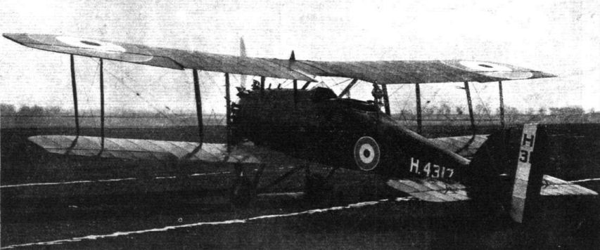
As the Austin Osprey was undergoing its flight trials in March 1918, the design of Austin’s last wartime military product was submitted to the Air Board on news that a new Specification was about to be issued for a Bristol Fighter replacement. The new design was the handsome Greyhound, a two-seat, two-bay biplane of strictly conventional appearance and construction. Unlike the privately-funded Sopwith Bulldog, the Greyhound was officially sponsored from the start and was therefore among the first aircraft to be allotted the new 320hp ABC Dragonfly I, a nine-cylinder aircooled engine on which many hopes were to be pinned. In due course the new Air Ministry’s Specification Type III was issued and the Greyhound seemed a promising contender for acceptance.
Designed by John Kenworthy, the Greyhound featured a flat-sided and fairly deep fuselage, the pilot and observer/ gunner enjoying an excellent field of view, this being partly afforded by a lower wing of narrow chord. The wings, rigged with moderate stagger, were of unequal span and chord, and carried ailerons top and bottom. The tail comprised fixed ventral and dorsal fins, with the tailskid integral with a triangular segment below the rudder - reminiscent of the S.E.5A. The rudder’s horn balance was faired to provide an unbroken outline with the dorsal fin.
Although quickly completed during the summer of 1918, under a contract signed on 18 May, the first of three prototypes was held up by prolonged engine trials, and it was the second aircraft, H4318, which underwent official evaluation at Martlesham Heath in January 1919. H4317 followed on 15 May that year, and remained with the A & AEE until September 1920. The third aircraft made its maiden flight in February 1920, the same month that H4318 was delivered to the RAE (the Factory at Farnborough having been renamed an Establishment to avoid confusion with the new RAF), but was damaged and written off after a landing accident on 29 August 1921.
Despite an enormous amount of work on it, the Dragonfly engine never truly succeeded in overcoming its fundamental mechanical weaknesses and brought about the abandonment of numerous promising aircraft, among them the attractive Greyhound. It might have proved possible to substitute another engine had such a decision been taken early on, but after the Armistice aircraft production contracts were being severely cut back, and the design staff at Austin was, in any case, quickly shrinking.
Type: Single-engine, two-seat, two-bay biplane fighter.
Manufacturer: The Austin Motor Co (1914) Ltd, Birmingham.
Air Ministry Specification: Type III of 1918.
Powerplant: One 320hp ABC Dragonfly I nine-cylinder air-cooled radial engine driving two-blade propeller.
Structure: All-wooden construction with fabric, ply and aluminium sheet covering.
Dimensions: Span, 39ft 0in; length, 26ft 8 1/2 in; height, 10ft 4in; wing area, 400 sq ft.
Weights: Tare, 1,838lb; all-up, 3,032lb.
Performance: Max speed, 134 mph at sea level, 126 mph at 10,000ft; climb to 10,000ft, 10 min 50 sec; service ceiling, 22,000ft; endurance, 3 hr.
Armament: Two synchronized 0.303in Vickers Mk I machine guns in nose, and one Lewis gun with Scarff ring on rear cockpit.
Prototypes: Three, H4317-H4319; all built, but no subsequent production.
Показать полностью
W.Green, G.Swanborough The Complete Book of Fighters
AUSTIN GREYHOUND UK
The Greyhound tandem two-seat fighter-reconnaissance aircraft was designed by J Kenworthy as a potential successor to the Bristol Fighter, but the first prototype was not completed until after the Armistice of 1918 owing to difficulties with its 320 hp ABC Dragonfly I nine-cylinder radial engine. Flight testing eventually commenced in May 1919, and three prototypes were built and flown, but no further development was undertaken. Armament comprised two fixed synchronised 0.303-in (7,7-mm) Vickers guns and a single 0.303-in (7,7-mm). Lewis gun on a Scarff ring in the rear cockpit.
Max speed, 129 mph (207 km/h) at 6,500 ft (1 980 m), 126 mph (203 km/h) at 10,000 ft (3 050 m).
Time to 10,000 ft (3 050 m), 10.83 min.
Endurance, 3 hrs.
Empty weight, 1,838 lb (834 kg).
Loaded weight, 3,032 lb (1375 kg).
Span, 39 ft 0 in (11,89 m).
Length, 26 ft 8 1/2 in (8,14 m).
Height, 10 ft 4 in (3,15 m).
Wing area, 400 sqft (36,16 m2).
Показать полностью
J.Bruce British Aeroplanes 1914-1918 (Putnam)
Austin Greyhound
THE Greyhound was the last military aircraft to be designed and built by the Austin Motor Co. during the 1914-18 war. It was a handsome two-seat two-bay biplane, intended to replace the Bristol Fighter as a fighter-reconnaissance type; and it represented an attempt to provide the performance and equipment considered necessary after the experience of four years of war.
The lines of the fuselage reflected a compromise between comparative simplicity of structure and aerodynamic and operational efficiency, based on the usual contemporary method of construction. The pilot sat fairly high and directly under a large cut-out in the trailing edge of the centre section, and his downward view was helped by the narrow chord of the lower wings. The observer was immediately behind the pilot, as in the Bristol Fighter, and had an excellent field of fire for his Lewis gun.
The equipment of the Greyhound included a camera, wireless, oxygen and heating apparatus. Its performance was by no means bad, and it seems a pity that this interesting type was not further developed. In common with so many of its contemporaries, of course, it suffered from the temperamental nature of its A.B.C. Dragonfly radial engine. If it had gone into production it would have required a different power unit, but it seems that no attempt was made to develop the Greyhound in any way after the failure of the Dragonfly engine. (The story of the A.B.C. Dragonfly is related in the history of the Nieuport Nighthawk).
SPECIFICATION
Manufacturers: The Austin Motor Co. (1914), Ltd., Northfield, Birmingham.
Power: 320 h.p. A.B.C. Dragonfly I.
Dimensions: Span: upper 39 ft, lower 36 ft 7 in. Length: 26 ft 8 1/2 in. Height: 10 ft 4 in. Chord: upper 6 ft 4-8 in., lower 4 ft 3 in. Gap: 4 ft 11 7/8 in. Span of tailplane: 12 ft 9 5 in.
Areas: Wings: 400 sq ft. Ailerons: each upper 14-8 sq ft, each lower 7-8 sq ft, total 45 2 sq ft. Tailplane: 27-2 sq ft. Elevators: 19-8 sq ft. Fin: upper 2-76 sq ft, lower 2-3 sq ft, total 5-06 sq ft. Rudder: 9-9 sq ft.
Weights: Empty: 1,838 lb. Military load: 324 lb. Crew: 360 lb. Fuel and oil: 510 lb. Loaded: 3,032 lb.
Performance: Maximum speed at 6,500 ft: 129 m.p.h., at 10,000 ft: 126 m.p.h., at 15,000ft: 121 m.p.h. Climb to 6,500 ft: 6 min 20 sec, to 10,000 ft: 10 min 50 sec, to 15,000 ft: 19 min 40 sec. Service ceiling: 22,000 ft. Endurance: 3 hours.
Tankage: Petrol: 66 gallons. Oil: 8 gallons.
Armament: Two fixed, synchronised Vickers machine-guns firing forwards; one Lewis machine-gun on Scarff ring-mounting on rear cockpit.
Serial Numbers: H.4317-H.4319.
Показать полностью
H.King Armament of British Aircraft (Putnam)
Greyhound. Designed in 1918, like its competitors the Bristol Badger and Westland Weasel, this intended Bristol Fighter replacement had two close-set, internally mounted synchronised Vickers guns firing through ports in the nose and a Lewis gun on a Scarff ring-mounting almost flush with the decking atop a narrow fuselage, which allowed an extensive field of fire. Fighting effectiveness was enhanced by the closeness of pilot and gunner. The reported ammunition supply of 1.700 rounds may indicate 500 rounds per gun for the pilot and seven double drums for the gunner.
Показать полностью
Jane's All The World Aircraft 1919
The Austin "Greyhound" represents one of the latest efforts to produce a fast quick climbing two-seater, fighting and reconnaissance biplane In general arrangement it follows standard practice. The fuselage carries in its nose a 320 h.p A.B.C. Dragonfly " engine A conical cowling covers the engine in with the exception of the cylinder head>, the shape of the cowling being preserved throughout the length of the fuselage by fairing. There is almost equal fin area above and below the fuselage. The upper main plane trailing edge is cut away, and the lower plane is of lesser chord than the upper, thereby giving the pilot a good view. Accommodation is made for the machine to carry three guns, camera, wireless, oxygen apparatus and heating apparatus.
Specification
Type of machine Two-seater Fighter, Reconnaissance Biplane
Name or type No. of machine "Greyhound"
Purposes for which intended Fighting and Reconnaissance.
Engine type and h.p. A.B.C. "Dragonfly", 320 h.p.
Span
Top plane, 39 ft;
bottom plane, 36 ft. 7 in.
Gap 4 ft 11 7/8 In.
Maximum height 10 ft 4 in.
Chord
Top plane, 6 ft. 4.8 in.;
bottom plane, 4 ft. 3 in.
Total surface of wings 400 sq. ft.
Span of tail 12 ft 9.5 In.
Total area of tail 47 sq. ft.
Total area of elevators 19.8 sq. ft
Area of rudder 9.9 sq. ft.
Area of fin
Top, 2.76 sq. ft
bottom, 2.3 sq. ft
Area of each aileron and total area
Two top, 14.8 sq ft.;
two bottom, 7.8 sq. ft;
total, 45.2 sq. ft
Weight of machine empty 2,050 lbs.
Load per sq. ft 7.72 lbs. per sq. ft
Weight per h.p. 10.3 lbs.
Tank capacity in hours 3 hours.
Tank capacity in gallons
Petrol 66 galls.,
oil 8 galls.
Weight of machine full 3,090 lbs. (Including guns, ammunition, &c.)
Performance (estimated).
Speed at 10,000 feet 130 m p.h.
Landing speed 45 m.p.h.
Climb. To 10,000 feet 11 minutes.
Показать полностью
C.Owers British Aircraft of WWI. Vol.7: Experimental Fighters Part 3 (A Centennial Perspective on Great War Airplanes 81)
The Austin Greyhound
Under the heading ‘Corps Reconnaissance, Fighter Reconnaissance, Night Reconnaissance’, the RAF Peace Establishment - Type Machines table compiled by the Technical Department and issued on 25 November 1918, lists the Bristol Badger along with the Westland Weasel and Austin Greyhound with Dragonfly engine, as the recommended type to meet these three classes that were then held by the Bristol Fighter. The design was stated to be ‘Ready’ and a competition would be held in February with a decision made by 1 March 1919.
The Austin Greyhound was another British fighter designed for 1919 that was to be powered by the ABC Dragonfly engine. Construction was underway by June 1918. Under the dual heading of:
RAF Type III.(a) Short Distance Fighter Reconnaissance
RAF Type III.(b) Corps Machine for Artillery Work
The Austin machine’s progress was set out against that of its competitors, the Westland Weasel and Bristol Badger in the Reports of the Design Branch, Technical Department - Aircraft Production as detailed hereunder.
F/E 12.06.18. Mock-up has been inspected and various improvements suggested. Detail design progressing.
F/E 26.06.18. Austin (Dragonfly) Contract for three machines. Mock-up of fuselage has been inspected & is being modified in accordance with various suggestions that have been made. 1st Machine. Wooden components of fuselage and planes progressing satisfactorily.
F/E 21.08.18. Contract for three machines. 1st machine. Erection of fuselage proceeding satisfactorily, and good progress is being made on the components for planes, tail unit and undercarriage, and on preliminary engine installation details.
F/E 04.09.18. 1st machine No. 4317. Erection of fuselage nearing completion. Guns, ammunition magazines, etc., now being fitted. Planes and tail unit being assembled. Some details of design require modifications for strength.
F/E 18.09.18. 1st machine No. 4317. Fuselage completely assembled in skeleton with engine bearer, sternpost, tail skid and top section in position. Planes complete in skeleton. Controls ready for fitting. Design passed for experimental flying.
F/E 02.10.18. 1st machine No. 4317. Machine now completed in skeleton. Controls and petrol tanks fitted.� F/E 16.10.18. 1st machine No. 4317. Completed in skeleton. Tail adjusting gear fitted. Work progressing on the fitting of controls and engine cowling.
F/E 30.10.18. 1st machine No. H4317. Machine is completely erected in skeleton. Alterations to the observer’s controls, camera fitting, etc., are being made and the machine will now be dismantled for covering.
F/E 13.11.18. 1st machine No. H4317. Machine has been dismantled for covering. Alterations to observer’s controls, camera, fittings, etc., are now in hand.
F/E 27.11.18. 1st machine No. H4317. Machine had been completely erected in skeleton and is now dismantled for covering. The wind screen is being altered to give the pilot better protection and easier access to the guns.
F/E 11.12.18. 1st machine No. H4317. Machine completed in skeleton and being covered. Petrol and oil tanks fitted and controls being connected up.
Period 12-31.12.18. 1st machine No. H4317. Engine had been delivered, and machine is ready to commence flying trials as soon as engine installation is complete.
Month ending 31.01.19. 1st machine No. H4317. Machine complete and ready for maker’s flying trials which will take place immediately.
The machine that emerged was a sleek looking two-bay biplane designed by J. Kenworthy who had previously worked for the Royal Aircraft Factory on their design staff. The Greyhound had two synchronised Vickers guns for the pilot with 1,700 rounds of ammunition, and the observer/gunner had a Lewis gun on a Scarff ring in the rear cockpit. The rear fuselage was shaped to give the observer a good field of fire. The two cockpits were placed close to each other so that communication between the crew would be easy.
The machine was of conventional wooden and wire braced construction with fabric covering. The wings were unequal in chord. The centre-section trailing edge was cut away which, with the narrower chord of the lower wing gave the pilot a good view. The fin and rudder bore traces of Kenworthy’s RAF influences resembling that originally designed for the S.E.5. Approximately equal fin area was carried above and beneath the fuselage.
The engine was covered by a conical cowl with the engine cylinders exposed. The shape of the cowling was preserved by fairings to the rear of the observer’s cockpit where it blended into the rectangular structure of the fuselage.
By the time the Greyhound was designed, the heights that aircraft were operating at required the carrying of oxygen and the Greyhound had this together with electrical heating for crew suits, camera and wireless equipment. Dual control was provided.
The first prototype, H4317, was flown to Martlesham Heath on 15 May 1919. The official tests were not conducted until August, however, being aware of the problems with the Dragonfly engine, this was probably the reason for the delay. While performance proved good, the Greyhound was doomed by the choice of the Dragonfly engine.
The second prototype, H4318, was received at Martlesham Heath on 11 October 1919, and up to that time had 9 hours 35 minutes flying time. From the aircraft's Log Book it appeared that no wing adjustment had been carried out. RAE Report No. K.1611 was made on the condition of H4218, the second prototype, after 24 hours 25 minutes flying, including the flying at Martlesham. From external examination of the wings, it appeared that they should be stripped. This was carried out and the following defects were found:
Wings:
(a). Nine long main ribs were broken, mostly through the flanges.
(b). Six of the smaller ribs in front of the ailerons were broken in the same way.
(c). Some of the end compression ribs were warped badly, the packing blocks were loose in several places throughout the wings.
Centre Section:
(a). The trailing edge had a piece about ten inches long completely broken out.
(b). Both end ribs were bowed badly.
(c). The centre main rib was broken at the rear end. In any case, the attachment of this rib was found to be very unsatisfactory.
(d). Rib flanges and packing blocks had come unglued in several places.
Fuselage and Tail:
Examination showed that the fuselage and tail were in good condition and no adjustments were required.
The ribs were found to been extremely light throughout, the flanges being only connected by vertical struts, no oblique struts being fitted between the spars. The distance between the spars in the Greyhound is 41” against 36” in the D.H. 9. and the ribs of the latter are very much stronger and stiffer.
The end ribs of the centre section were both bowed inwards badly. These ribs were also light and did not appear strong enough to take the loads. They were stiffened by light stringers that had little effect in preventing bowing. This criticism was also applied to the end ribs of the wings to some extent although they were solidly made. They are, however, quite unsupported over the 41” span except by light stringers, and they should certainly be stiffened by oblique struts if not replaced by a box rib. It is quite possible that a box rib could be designed to weigh little more than the present rib with satisfactory supporting struts.
The compression ribs and spars were in good condition and despite the broken ribs, the internal bracing of the wings did not require any adjustments.
While the fuselage and tail were in good condition it was noted that the machine had only done 24 1/2 hours.
The rudder bar had been strengthened but was again found to have buckled and was further strengthened by replacing the 20 SWG bar to 16 SWG. The report concluded by noting that the ribs were being strengthened by the addition of struts and the end ribs were being stiffened.
The third aircraft, H4319 had a slightly different fin and rudder as well a revised fuel system.
The Austin Company proposed a mail-carrying version of the Greyhound. The pilot’s cockpit was to be moved back and a mail compartment constructed forward. Fuel capacity was increased to 91 gallons to give it a good range. The idea did not progress beyond a paper project.
H4318 survived at least until June 1922, when it was flying at the RAE, making its last recorded flight on the 12th of that month.
Austin Greyhound Specifications
Source 1 2
Span top 39 ft 39 ft
Span bottom 36 ft 7 in 36 ft 7 in
Chord top 6 ft 4.8 in -
Chord bottom 4 ft 3 in -
Length - 26 ft 8 1/2 in
Gap 4ft 11 7/8in -
Height 10 ft 4 in -
Span tailplane 12 ft 9.5 in -
Wing & Aileron Area ft2 400 400
Aileron Area Top, ft2 29.6 -
Aileron Area bottom, ft2 15.6 -
Aileron Area total, ft2 45.2 -
Tail Area, ft2 47 -
Elevator Area, ft2 19.8 -
Rudder Area, ft2 9.9 -
Fin top Area, ft2 2.76 -
Fin bottom Area, ft2 2.3 -
Empty Wt, lbs 2,050 -
Gross Wt, lbs 3,090 -
Petrol, gallons 66 -
Oil, gallons 8 -
10,000 ft 11 min 10 min 50
15,000 ft - 19 min 40
Endurance - 3 hrs
Landing speed, mpt 45 -
Speed at 6,500 ft - 129
Speed at 10,000 ft 130 126
Speed at 15,000 ft - 121
Service ceiling, ft - 19,000 ft
Engine 320-hp Dragonfly.
Sources:
1. Jane’s All the World’s Aircraft 1919.
2. J.M. Bruce data.
Показать полностью