В.Кондратьев Самолеты первой мировой войны
ФРИДРИХСХАФЕН G-II/G-III / FRIDRICHSHAFEN G-II/G-III
Фирма Флюгцойгбау Фридрихсхафен, более известная своими поплавковыми гидропланами, еще в 1914 году предприняла попытку создания двухмоторного бомбардировщика. Но самолет (фабричное обозначение FF-30) получился неудачным и не пошел в серию.
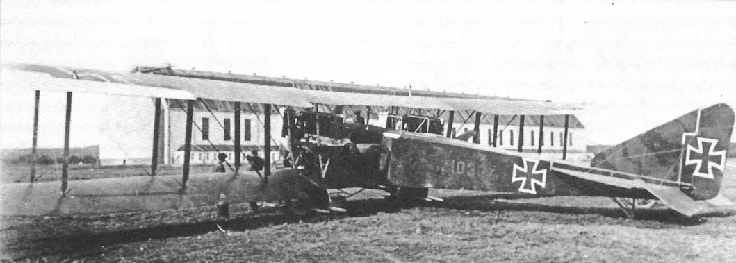
К идее тяжелых многомоторных машин фирма вернулась в 1916 году, вероятно, под влиянием известий об успехах бомбардировщиков "Гота". Следующий образец Фридрихсхафена - двухмоторный двухстоечный биплан FF38 в конце 1916-го приняли на вооружение под индексом G-II. Однако машина обладала слишком малой для своего класса бомбовой нагрузкой. Было построено всего несколько экземпляров, применявшихся на западном фронте в 1917 году.
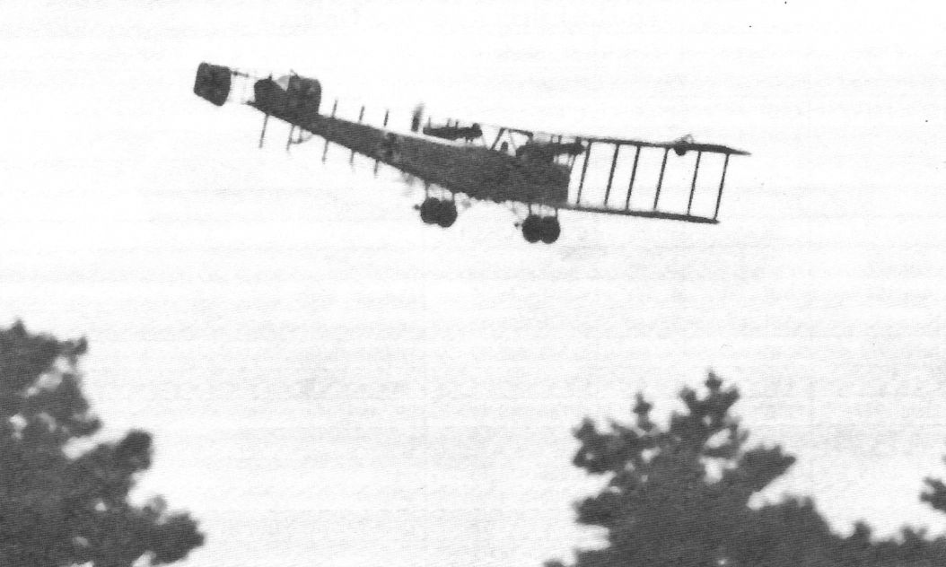
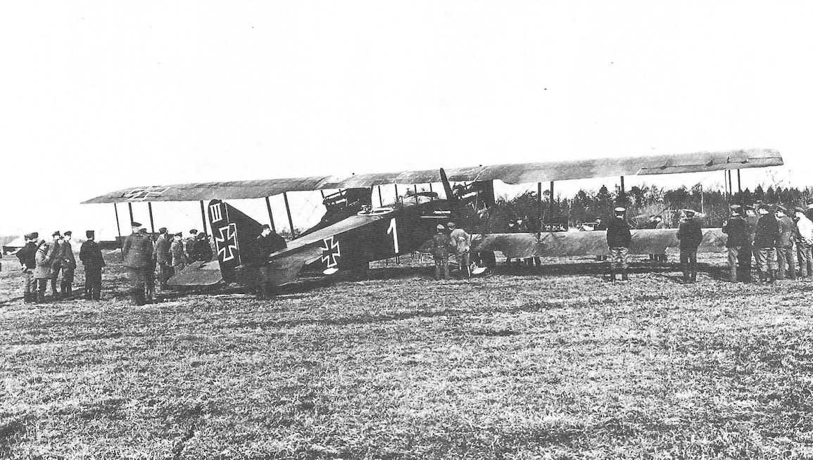
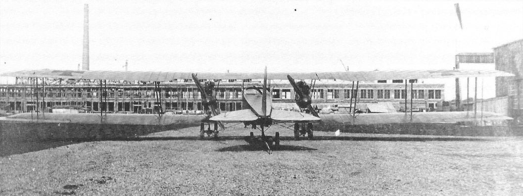
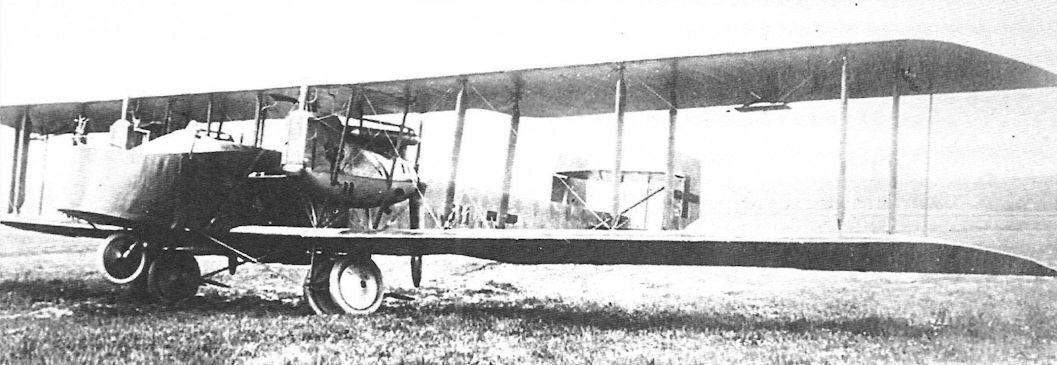
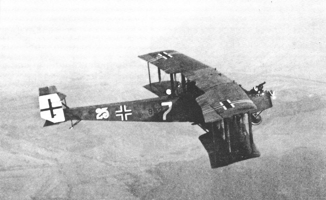
Гораздо большее распространение получила очередная модель "Фридрихсхафен" G-III (FF45), составившая серьезную конкуренцию бомбовозам фирмы Гота. Новый "Фридрихсхафен" появился в начале 1917 года, примерно тогда же, когда Гота испытывала свой знаменитый G-IV. Не знаю, можно ли тут говорить о заимствовании, но оба самолета получились чрезвычайно похожими друг на друга. Даже геометрические размеры и массы совпадали с удивительной точностью.
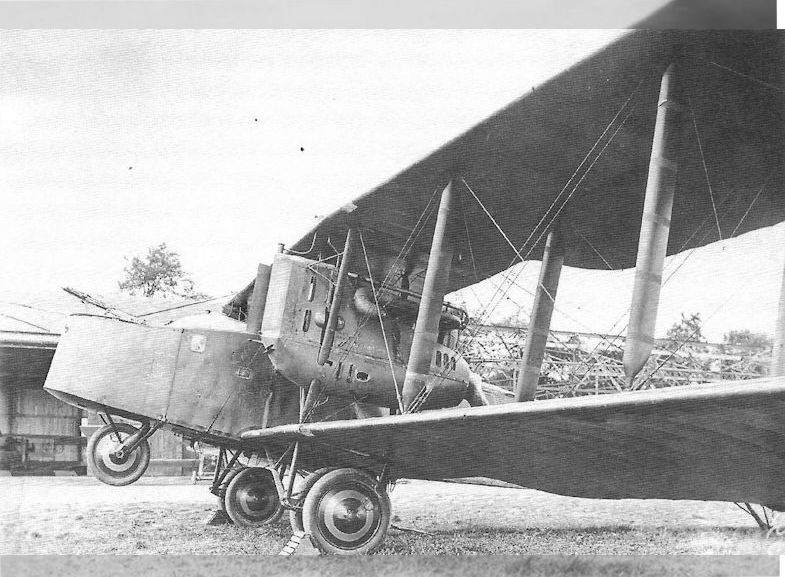
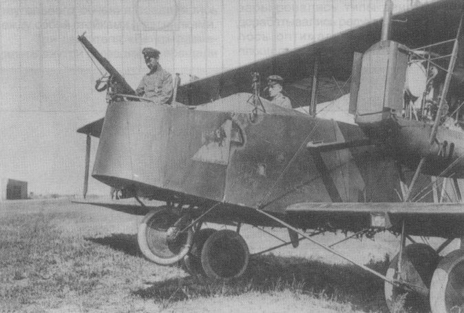
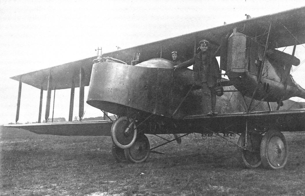
Кроме того, обе машины оснащались одинаковыми двигателями, только на "Фридрихсхафене" они не крепились к нижнему крылу, а "подвешивались" на стойках, как это позднее сделали на "Готе" G-V. Другими внешними отличиями "Фридрихсхафена" была несколько иная форма оперения и носовое противокапотажное колесо.
Конструкция самолета смешанная. Ряд силовых элементов крыла и фюзеляжа, а также каркас оперения выполнен из стальных труб. Обшивка тоже смешанная: в передней части фюзеляжа и центроплане нижнего крыла - фанерная, а на остальных поверхностях - полотно. Экипаж - 3 человека: летчик, носовой стрелок-бомбардир и хвостовой стрелок.
Летные характеристики "Фридрихсхафена" в целом соответствовали данным "Готы", но бомбовая нагрузка оказалась в полтора раза выше. Самолет приняли на вооружение в качестве дальнего бомбардировщика и запустили в серию.
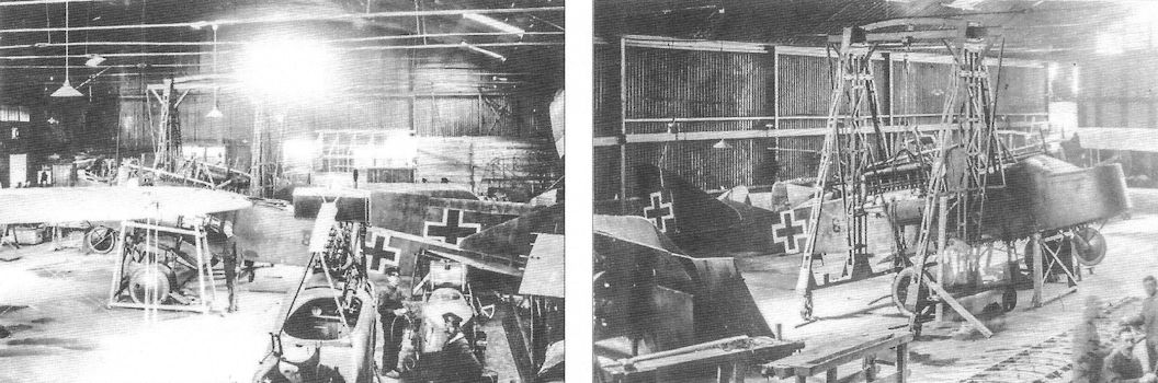
Помимо фирмы-разработчика, "Фридрихсхафены" G-III выпускали заводы Ханзейтиш Флюгцойгверк (Ганза) и Даймлер Флюгцойгбау. В небольших количествах строилась также модификация G-IIIa с двухкилевым бипланным оперением и без носового колеса. Всего построено 245 бомбардировщиков обоих типов.
"Фридрихсхафены" до конца войны применялись наряду с "Готами" в качестве дневных и ночных бомбардировщиков против целей во Франции, Бельгии и Великобритании. В дальнейшем немцы использовали уцелевшие машины в качестве транспортно-пассажирских.
В 1920 году два таких самолета были закуплены советской Россией и еще несколько лет летали в составе Красного воздушного флота. Еще один аппарат, совершивший вынужденную посадку на территории Литвы, после ремонта состоял в литовских ВВС.
ДВИГАТЕЛИ
2 мотора "Мерседес" D.IVa по 260 л.с.
ВООРУЖЕНИЕ
Носовая и хвостовая турели с пулеметами "Парабеллум". Бомбовая нагрузка G-II - 170 кг, a G-III - до 900 кг бомб.
ЛЕТНО-ТЕХНИЧЕСКИЕ ХАРАКТЕРИСТИКИ
Размах, м 23,7
Длина, м 12,8
Площадь крыла, кв.м 92,7
Сухой вес, кг 2695
Взлетный вес, кг 3946
Скорость максимальная, км/ч 141
Продолжительность полета, час,мин 5,0
Время набора высоты, мин/м 20/3000
Потолок, м 3000
А.Александров, Г.Петров Крылатые пленники России
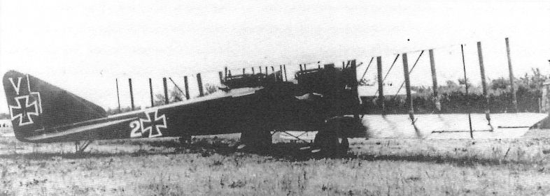
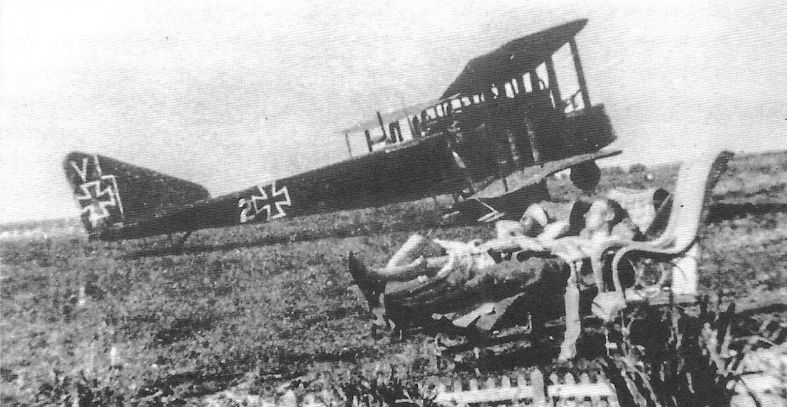
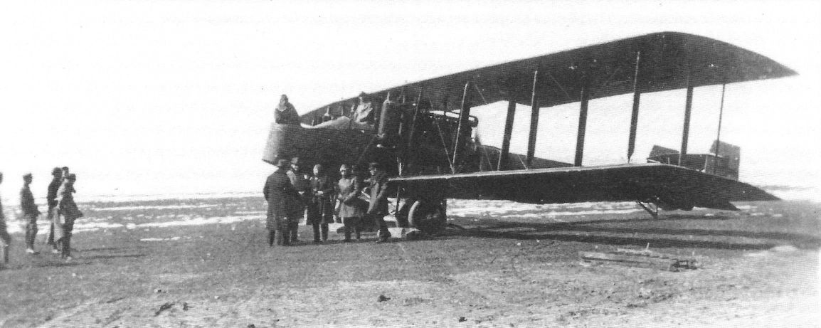
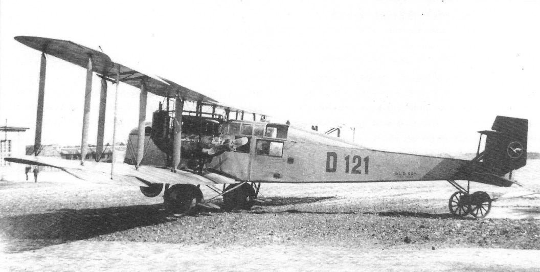
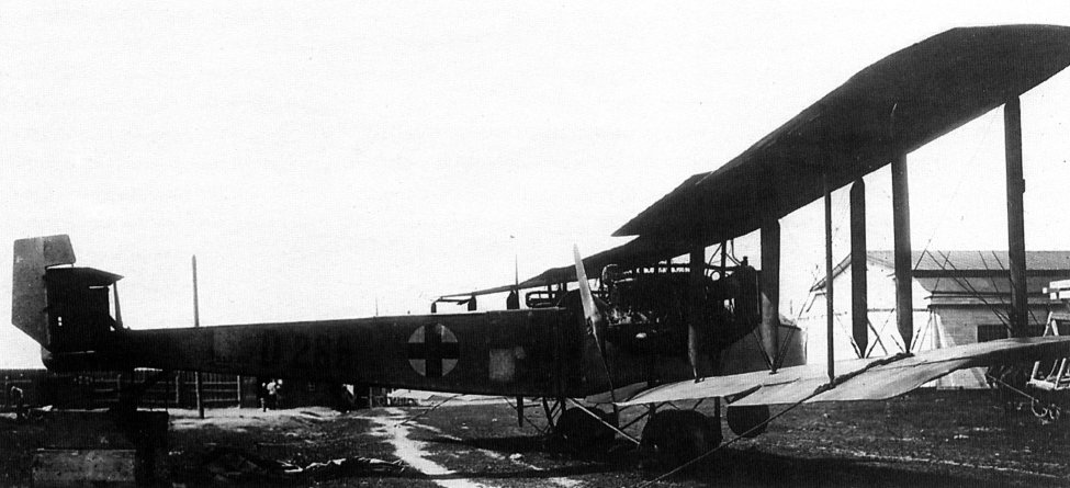
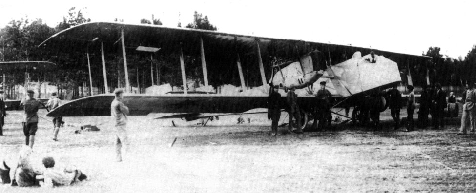
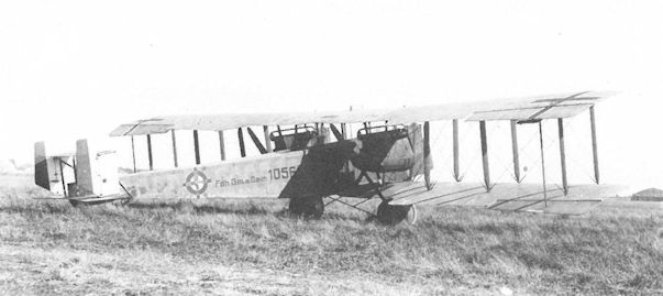
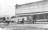
Бомбовая нагрузка "Румплеров" последней модификации составляла 250 кг, тогда как "Фридрихсхафен Г. III" спокойно поднимал 800 кг смертоносного груза, а в максимальном варианте - 1500 кг. Самолеты этого типа, случалось, разбойничали в небе над Парижем и, возможно, участвовали в налетах на Англию, совершаемых аэропланами "Гота". Под руководством инженера Теодора Кобера третья модель фридрихсхафенских тяжелых бомбардировщиков родилась в начале 1917 г. Машина двигалась двумя толкающими "Мерседесами" 260 л. с. и являла собой трехместный трехстоечный однокилевой биплан с оборонительным вооружением из 2-3 пулеметов на турельных установках. В 1918 г. модель немного доработали, оборудовав хвостовым оперением бипланного типа - так появился "Фридрихсхафен Г. IIIа". Три компании собрали 236 самолетов ранней модификации и 280 - поздней, такие масштабы, увы, даже не "снились" отечественной промышленности. В России "Фридрихсхафены" очутились случайно, и вовсе не в боевой роли. В январе - феврале 1920 г. по просьбе австро-германской репатриантской комиссии по делам военнопленных "Германское общество воздухоплавания" направило из Кенигсберга в Смоленск 4 гражданских бомбовоза, груженных медикаментами и везших парламентеров. Один из самолетов совершил вынужденную посадку в Польше, но 3 других долетели благополучно. Далее случилось непредвиденное: 2 машины, с заводскими номерами 202 и 282, были конфискованы советскими властями и только третьему, с пилотом Вилли Польт (Willi Polte) за штурвалом, позволили лететь обратно, да и то лишь потому, что он повез советских торгпредов в Берлин. По прихоти судьбы этот "Фридрихсхафен" после обстрела с земли с пробитыми баками спустился в Литве, где его, вероятно, "оприходовали" местные правители. Что касается оставшихся в России, то один использовался в Авиазвене особого назначения, затем при штабе 1-й авиаэскадры в Москве, а другой служил на Украине и в Западном военном округе. Предположительно, оба могли перевозить до 8 пассажиров каждый. На представленных здесь фотографиях изображены самолет "Германского общества воздухоплавания" (Deutsche Luftreederei = D. L. R.) с номером компании Д. Л. P. 512 и регистрационным Д 286, помимо которых на борту фюзеляжа виден красный крест (84), и аппарат Красной авиации со звездой на нижнем крыле (85).
На борту одного из советских самолетов "Фридрихсхафен Г.IIIa" находился однажды страшный человек. Речь идет о Л. Д. Троцком, председателе Реввоенсовета Республики в 1920 - 1921 гг.
На фотографии цифрами обозначены: 1 - Троцкий, 2 - жена Троцкого, 3 - пилот Буоб.
Заслуживает внимания уже сама последовательность распределения номеров, тогда как место и время действия не указаны, равно как и личности остальных из собравшихся.
В Советской России И. А. Буоб являлся пионером дальних перелетов. В июле 1919 г. на аэроплане "Эльфауге" он с курьером на борту преодолел расстояние около 1000 км (из них примерно 600 км над территорией противника), чтобы доставить сообщения штабу Туркестанского фронта.
J.Herris Friedrichshafen Aircraft of WWI (A Centennial Perspective on Great War Airplanes 21)
Friedrichshafen G.I
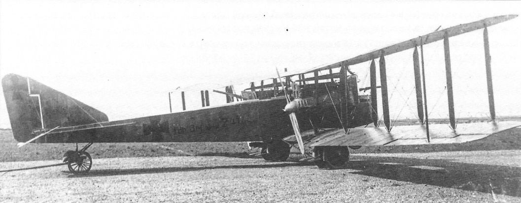
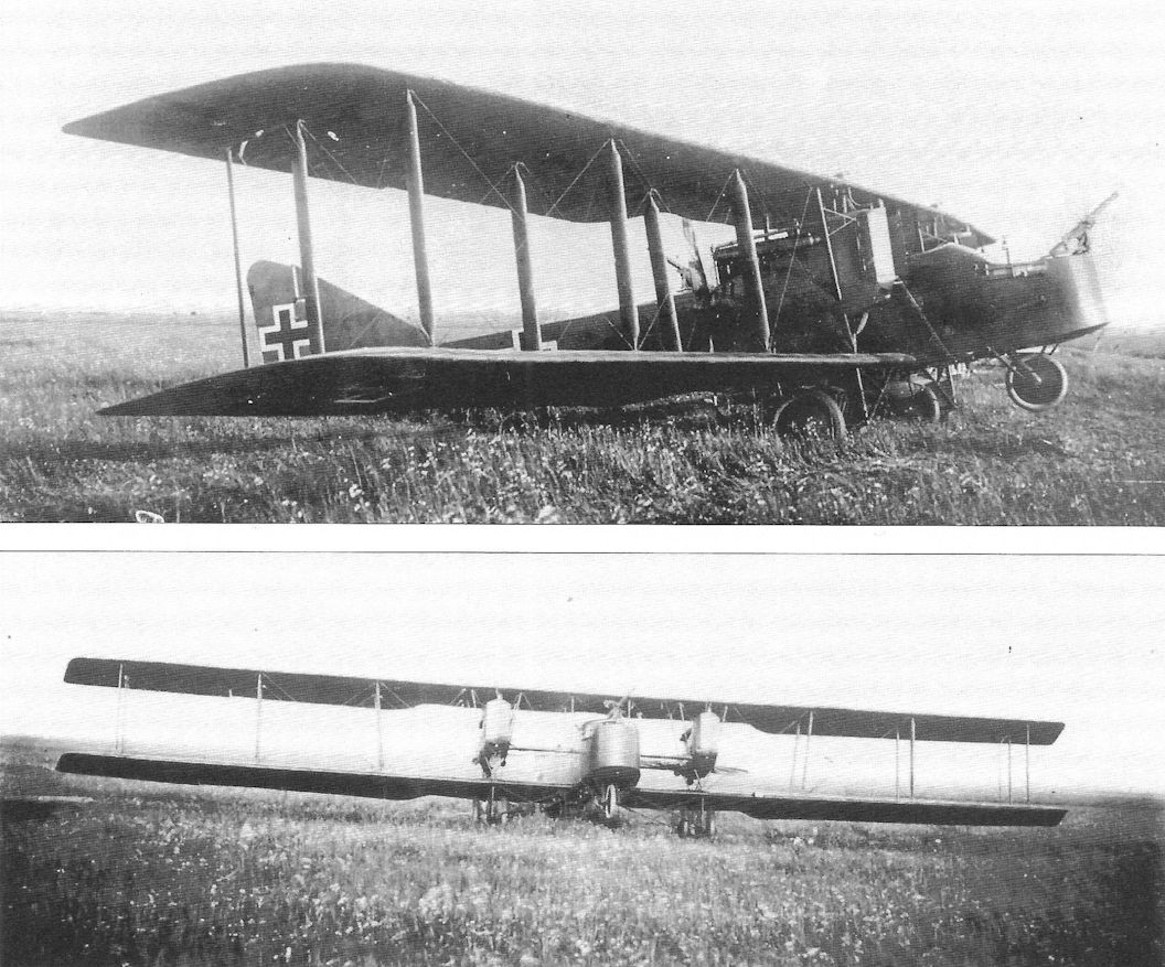
Only a single Friedrichshafen G.I, 118/15, was built in 1915. This prototype was powered by two 150 hp Benz Bz.III engines mounted as pushers, and it featured three-bay wing bracing and a biplane tail assembly. Built to the original Kampfflugzeug (battle plane) specifications that Idflieg issued in 1914, the Kampfflugzeug concept was basically an 'aerial cruiser' armed with machine guns and bombs. The aircraft was to have 200 hp, carry a crew of three, and have an endurance of six hours. Unfortunately, the battleplane was a flawed concept.
The Friedrichshafen G.I, factory designation FF36, had a crew of three and a single flexible machine gun in the front gunner's cockpit. Construction of the G.I was the conventional wood frame with wire bracing and fabric covering common for the time. Testing was sufficiently promising that Idflieg ordered an improved follow-on design, the G.II.
Friedrichshafen G.II
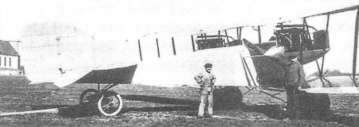
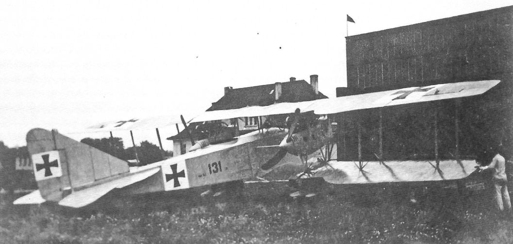
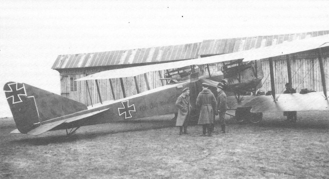
After evaluating the Friedrichshafen G.I, Idflieg ordered six examples of an improved, more powerful derivative, the Friedrichshafen G.II, factory designation FF38. Following the basic configuration and construction of the G.I, the G.II differed by having two 200 hp Benz Bz.IV engines, more compact two-bay wing bracing, and a conventional monoplane tail, although the first prototype was also tested with a 'box' tail for comparison. The specified bomb load was 150 kg, an indication the Kampfflugzeug was evolving into a bomber. Another indication was that a second flexible machine gun was installed for a rear gunner.
These first aircraft had serial numbers G.131-136/15, indicating they were ordered in late 1915. A second batch of a dozen G.II bombers, serials G.100-111/16, was ordered in February 1916. Unfortunately, the prototype was damaged in a crash during testing. Details are not known, but the result was the fuselage and lower wing structure had to be revised before the G.II was approved for production and operational service. The changes were made in May and the type testing was done in July and August, after which the modified prototype was approved for operational service.
However, the first six G.II bombers were apparently retained for a variety of test and experimental programs. For some reason additional modifications to the wings were required, and these were load-tested on October 14. On November 24 a revised tail structure was load tested. Aircraft G.105/16 was accepted on December 1, 1916, an indication that G.II production was completed early in 1917. In addition to the 18 G.II bombers ordered from Friedrichshafen, a like number were ordered from Daimler as the Friedrichshafen G.II(Daim). Only 35 G.II bombers were delivered as G.104/16 became the G.III prototype.
Friedrichshafen G.III / G.IIIa
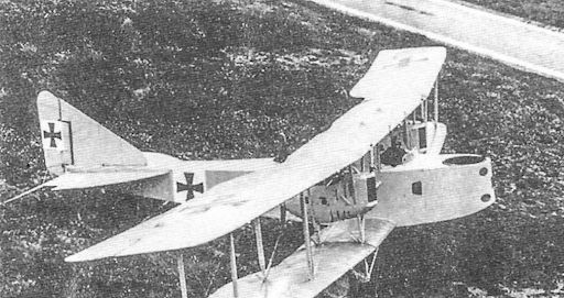
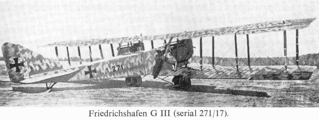
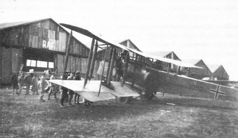
The Friedrichshafen G.III, factory designation FF45, was an enlarged, more powerful development of the Friedrichshafen G.II. Following the basic configuration and construction of the G.II, the G.III differed by having two 260 hp Mercedes D.IVa engines and larger three-bay wings to enable it to carry a heavier bomb load. The G.III also added a nose wheel under the forward gunner's cockpit to prevent nose-overs on landing. This was important because most German bomber losses were due to bad landings, especially at night. The G.III was under development as early as July 1916, well before the G.II reached the front or was even approved for operational service. As noted above, airframe G.104/16 became the G.III prototype.
In November 1916 Idflieg ordered 24 production G.III bombers, serials G.1030-1053/16, with the first becoming the type aircraft, the production standard. This aircraft was flying by March 18, but was not sent to Adlershof for the type test until the designer, Kober, was satisfied with its performance and flying qualities. To improve maneuverability, ailerons were added to the lower wings. G.III 1030/16 was approved for operational service on April 17 providing it successfully performed the three-hour flight, passed the static load tests, and some minor installation and structural defects were fixed. These were easily corrected and the G.III was at the front by June 1917.
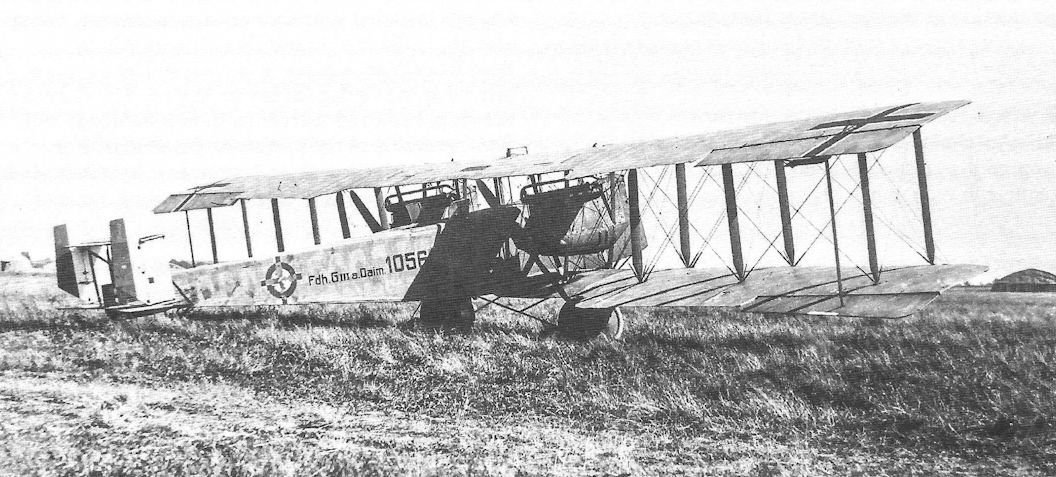
The G.III was also produced under license by Daimler as the G.III(Daim), Daimler already having produced the Friedrichshafen G.II under license. Idflieg ordered the first Friedrichshafen G.III(Daim) bombers in May 1917. On August 10 Daimler-built bomber G.240/17 passed the three-hour acceptance flight and bomber G.241/17 completed the Typenprufung (Type Test) at Adlershof on August 22. Daimler was required to correct more than 30 minor installation defects and the G.III(Daim) was then approved for operational use. In addition to Daimler, the Friedrichshafen G.III was also ordered from the Caspar Hanseatische Flugzeugwerke, a total of 35 aircraft being produced as the Friedrichshafen G.III(Hansa). The Type Test of this license-built G.III was not completed until July 1918.
Although the Gotha bombers became far more famous due to bombing London by day and later by night, the Friedrichshafen G.III was a better aircraft. Used for tactical bombing, the Friedrichshafen G.III had better flying characteristics than the Gotha, which became dangerously tail-heavy after dropping its bombs. In addition to being more stable in flight, the Friedrichshafen G.III also had a more robust landing gear. Both characteristics became more important as bombers transitioned to night bombing due to improved Allied defenses.
Different engines were tested to improve high- altitude performance. Maybach Mb.IVa engines of 260 hp were tried in one G.III, which improved its climb rate to 5,000 m in 42 minutes, a welcome improvement over the standard aircraft. Another G.III(Daim), 245/17, was tested with the overcompressed 260 hp Mercedes D.IVau engine in January 1918. However, a combination of limited availability of the altitude engines and the switch to night bombing, which was done at lower altitudes, meant the altitude engines were reserved for the high-altitude reconnaissance aircraft that needed them. High reliability was far more important to night bombers than high-altitude performance.
In fact, for night bombing the first priority was reliability of the airframe and engines, followed by increased bomb load. By January 1918 Kogenluft wanted the payload increased to 1,000-1,200 kg. Next in priority were good take-off and landing qualities, good flying qualities, maneuverability, and the ability to maintain controlled flight despite an engine failure.
Friedrichshafen addressed these needs with modifications to the basic G.III airframe. A version of the G.III with biplane tail created the G.IIIa. Another derivative with increased wing area became the G.IV, and yet another derivative with tractor propellers became the G.V. Flettner assisted controls were used on the G.IIIa and G.IV, and another G.III was tested with mid-wing ailerons; but these did not go into production.
G.IIIa & G.IIIb
Interestingly, the biplane or 'box' tail had been used on the first Friedrichshafen bomber, the sole G.I prototype. Now a similar tail was tested on the G.III in two versions, with and without a central fin supporting the upper stabilizer. The purpose was to improve directional control after an engine failure. The box tail (Kastensteuer) without fixed fin was chosen for production after comparative flight trials were completed in late March 1918. With box tail and a number of additional modifications to improve operational effectiveness, the bomber was designated Friedrichshafen G.IIIa.
At Idflieg’s urging during a bomber conference that started April 3, 1918, both Friedrichshafen and Daimler agreed to install the box tail on G.III bombers already in production. The additional changes were made when the G.IIIa entered production, the first being delivered by Friedrichshafen in June 1918, from which time the G.IIIa began to replace the G.III. At this same bomber conference it was decided to modify the bomber to enable crewmen to easily move between the forward and aft gun positions. This change resulted in the G.IIIb designation, which essentially included all the G.IIIa modifications together with a passageway on the starboard side. The drawings were completed in July and an unknown number of bombers were completed as the G.IIIb.
The G.IIIa proper embodied a number of modifications in addition to the box tail. A new fuel system with increased fuel capacity enabled flight durations up to six hours. A Flettner servo-tab (Hilfsruder - assisted rudder) system was fitted to the upper ailerons to reduce the pilot's control forces for easier flight and improved maneuverability. For greater bomb load the standard useful load was increased to 1,500 kg, and the maximum permissible load was increased to 2,100 kg. The landing gear was modified to increase clearance to mount larger bombs under the fuselage. Finally, a Gotha-style gun tunnel was installed in the fuselage to improve the rear gunner's downward field of fire, a change necessitated by increased British night fighter activity. Daimler also changed to G.IIIa(Daim) production as did the Caspar Hanseatische Flugzeugwerke, a total of 40 aircraft being ordered as the Friedrichshafen G.IIIa(Hansa) on July 13, 1918.
Austro-Hungarian Involvement
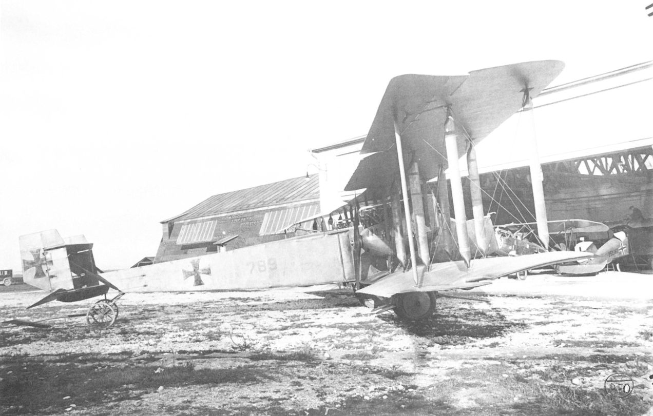
The Austro-Hungarian Luftfahrtruppe (LFT} also wanted the Friedrichshafen G.III, but their initial request in November 1917 was refused. In place of the Friedrichshafen G.III the LFT was offered the Gotha G.IV and purchased a batch of 40. However, Germany did release one Friedrichshafen G.III airframe to the LFT in April or May 1918 for the LFT to explore the possibility of license production. Meanwhile the Gotha G.IV(LVG) bombers in LTF service were experiencing severe problems that rendered them virtually useless, and the LFT again requested 50 Friedrichshafen G.III bombers. This time the request was approved, but a large fire at the Friedrichshafen factory on the night of April 13/14, 1918 precluded fulfilling the order. Due to increased license production by Daimler and Hansa, Idflieg finally approved the sale of 20 Friedrichshafen G.IIIa(Daim) bombers to the LFT on August 1, but none were delivered. On May 18, 1918 the Austro-Hungarian Fliegerarsenal awarded a contract for 100 bombers to the Oesterreichishe Flugzeugfabrik AG (Oeffag), 50 of which were to be the Friedrichshafen G.IIIa, which the LFT regarded as the most effective German two-engine bomber at that time. Two Friedrichshafen G.IIIa aircraft with Austro-Hungarian engines installed were sent as pattern aircraft. These aircraft, G.IIIa 789/17 and 790/17, with 250 hp Benz Bz.IV(Mar) engines, were shipped by train and arrived at the Oeffag factory in August. The German drawings had to be revised to Oeffag standards and final assembly of the prototype, Friedrichshafen G.IIIa(Oef) 54.01 began in September. However, with the Austro-Hungarian Empire crumbling, none of these bombers were completed before the Armistice.
Friedrichshafen Bomber Orders
Date Type Qty Serials Notes
1915 G.I 1 G.118/15
Late 1915 G.II 6 G.131-136/16
Feb. 1916 G.II 11 G.100-113/16 G. 104/16 was the G.III prototype
Oct. 1916 G.II 12 G.625-636/16 Daimler built. G.637-648/16 not built.
Feb. 1917 G.II 6 G.150-155/17 Daimler built
Nov. 1916 G.III 24 G.1030-1053/16
May 1917 G.III 25 G.156-180/17
May 1917 G.III 30 G.240-269/17 Daimler built
June 1917 G.III 100 G.270-369/17
July 1917 G.III 60 G.373-432/17 Daimler built
Sep. 1917 G.III 6 G.554-559/17 Daimler built
Dec. 1917 G.III / IIIa 60 G.784-843/17
Dec. 1917 G.III 4 2 Daimler built; serials in range G.433-442/17?
Feb. 1918 G.III 100 G.355-414/18 G.505-544/18
Feb. 1918 G.III 35 G.150-184/18 Hanseatische built; serials unconfirmed
April 1918 G.III 100 G.645-744/18
April 1918 G.III 50 G.1400-1449/18
April 1918 G.III 50 G.1793-1827/18 Ordered from Gotha; not built
April 1918 G.III / IIIa 30 G.750-779/18 Daimler built
June 1918 G.IIIa 50 G.780-829/18
June 1918 G.IIIa 30 G.880-909/18 Daimler built
July 1918 G.IIIa 150 G.830-879/18 G.1160-1209/18
July 1918 G.IIIa 45 G.1000-1044/18 Daimler built
July 1918 G.IIIa 40 G.1120-1159/18 Hanseatische built
Sep. 1918 G.IIIb / G.IV 100 G.1465-1564/18
Oct. 1918 G.IIIa / G.IV 75 G.1045-1119/18 Daimler built
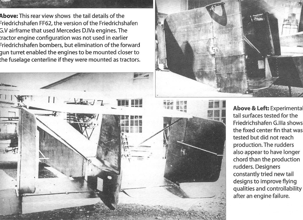
1918 G.V 3 G.900-902/17? FF62 used the G.V airframe, Mercedes engines
Friedrichshafen Bomber Specifications
G.I G.II G.III G.IIIa G.IIIa(Daim) G.IV G.V
Engines 2x150 hp Benz Bz.III 2x200 hp Benz Bz.IV 2x260 hp Mercedes D.IVa 2x260 hp Mercedes D.IVa 2x260 hp Mercedes D.IVa 2x260 hp Mercedes D.IVa 2x245 hp Maybach Mb.IVa
Span - 19.75 m 24.0 m 24.0 m 24.05 m 22.60 m 19.20 m
Wing Area - 75.5 m2 94.26 m2 94.86 m2 - 87.00 m2 76.00 m2
Gap - 2.10 m 2.11 m - - - -
Length - 11.05 m 12.78 m 12.24 m 12.65 m 12.00 m 10.00 m
Height - 3.41 m 3.54 m - 3.40 m - -
Empty Wt. - 2,180 kg 2,560 kg 2,700 kg 3,000 kg 2,880 kg 2,410 kg
Loaded Wt. - 3,180 kg 3,795 kg 4,200 kg 4,500 kg 4,980 kg 4,214 kg
Useful Load - 1,000 kg 1,235 kg 1,500 kg 1,500 kg 2,100 kg 1,804 kg
Max Speed - 150 km/h 150 km/h 140 km/h 140 km/h 142 km/h -
Climb: 1,000 m - - 3.5 min. - - - -
2,000 m - - 10.5 min. - - - -
3,000 m - - 20 min. - - - -
4,000 m - - 36 min. - - - -
5,000 m - - 74.5 min. - - - -
Notes: 1. The G.I &. G.V were fitted with one flexible machine gun; the other types had two flexible machine guns. 2. The G.V airframe was also tested with 260 hp Mercedes D.IVa engines.
O.Thetford, P.Gray German Aircraft of the First World War (Putnam)
Friedrichshafen G I
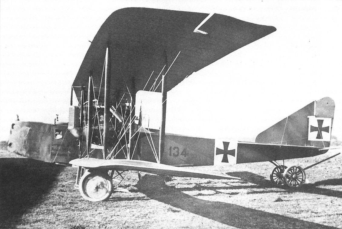
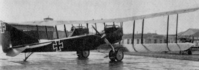
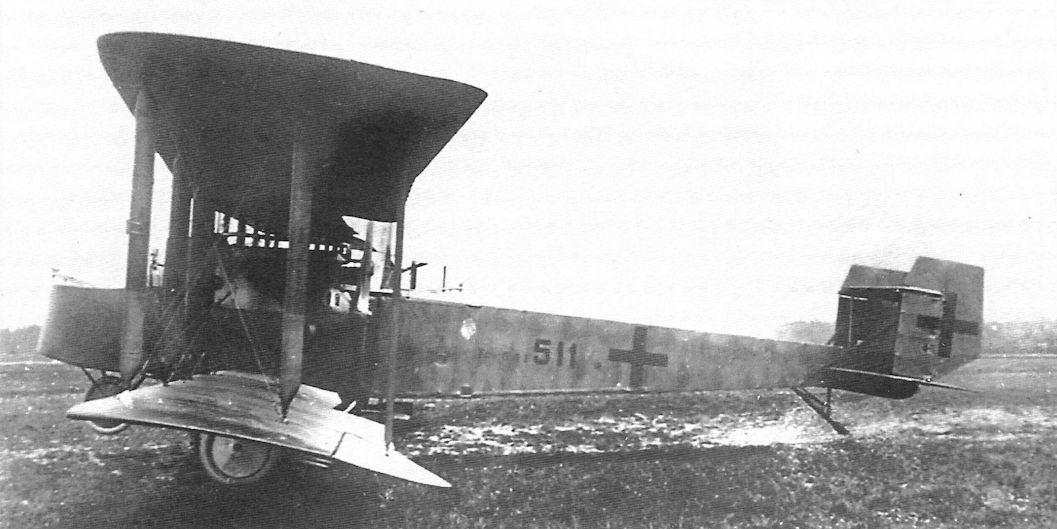
First of the twin-engined bombers built by Friedrichshafen in 1915, the three-bay G I paved the way for the G III, from which it differed mainly in having a biplane tail. A crew of three was carried. Power was twin 150 h.p. Benz Bz III engines driving pusher airscrews. A manually operated Parabellum machine-gun was carried in the nose cockpit.
Friedrichshafen G II
Built during 1916, the G II was a neat twin-engined design for its period and, unusually, had only two-bay outer wing panels. It was a reasonably successful aircraft and passed into limited production. The attachments behind the wheels were to prevent stones and mud being flung into the neatly spinnered, pusher airscrews. Engines, two 200 h.p. Benz Bz IV. Span, 20.3 m. (66 ft. 7 3/8 in.). Length, 11.05 m. (36 ft. 3 in.). Height, 3.6 m. (11 ft. 9 3/4 in.). Area, 70 sq.m. (756 sq.ft.). Weights: Empty, 2,200 kg. (4,840 lb.). Loaded, 3,152 kg. (6,934.4 lb.). Armament, one manually operated Parabellum machine-gun in nose cockpit and another aft of the wings.
Friedrichshafen G III
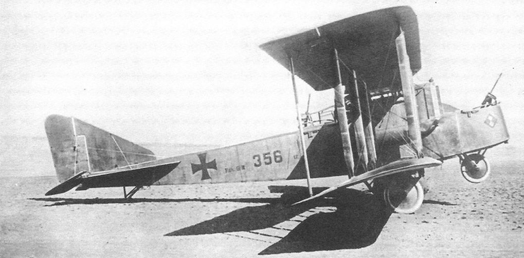
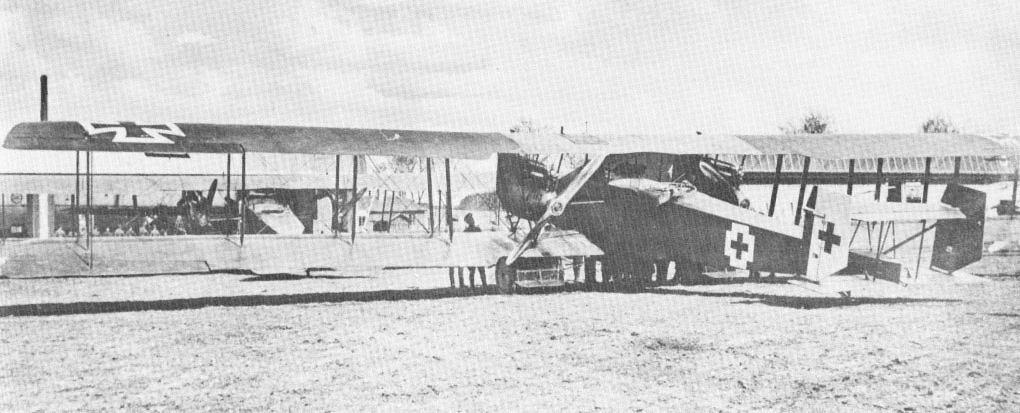
In company with the Gotha G V, the Friedrichshafen G III twin-engined bomber formed the backbone of the German Bombengeschwader force on the Western Front from early 1917 until November 1918. For the most part these aircraft were used for long-distance night raids, and on several occasions were used in raids on Paris. They were probably used, together with Gothas, in raids upon Great Britain, but certain confirmation is not to hand. Although very similar in size and layout to their Gotha brethren, the Friedrichshafens could be distinguished by their raked wingtips with aileron horn balances inset. They also had distinctive tail surfaces, the chord of which was greater than the span. The G III was a larger and more powerful three-bay version of the earlier two-bay G II, which was produced on a small scale. On 16th February 1918 a G III was brought down reasonably intact by A.A. fire and became the subject of a detailed Allied report.
Full crew complement of the Friedrichshafen G III was three: pilot, gunner and a bombing officer, who also "doubled" as gunner when necessary. In practice, the number of the crew often varied, and G IIIs were sometimes operated by only two crew members, this being facilitated by the intercommunication of the cockpits enabling places to be changed during flight.
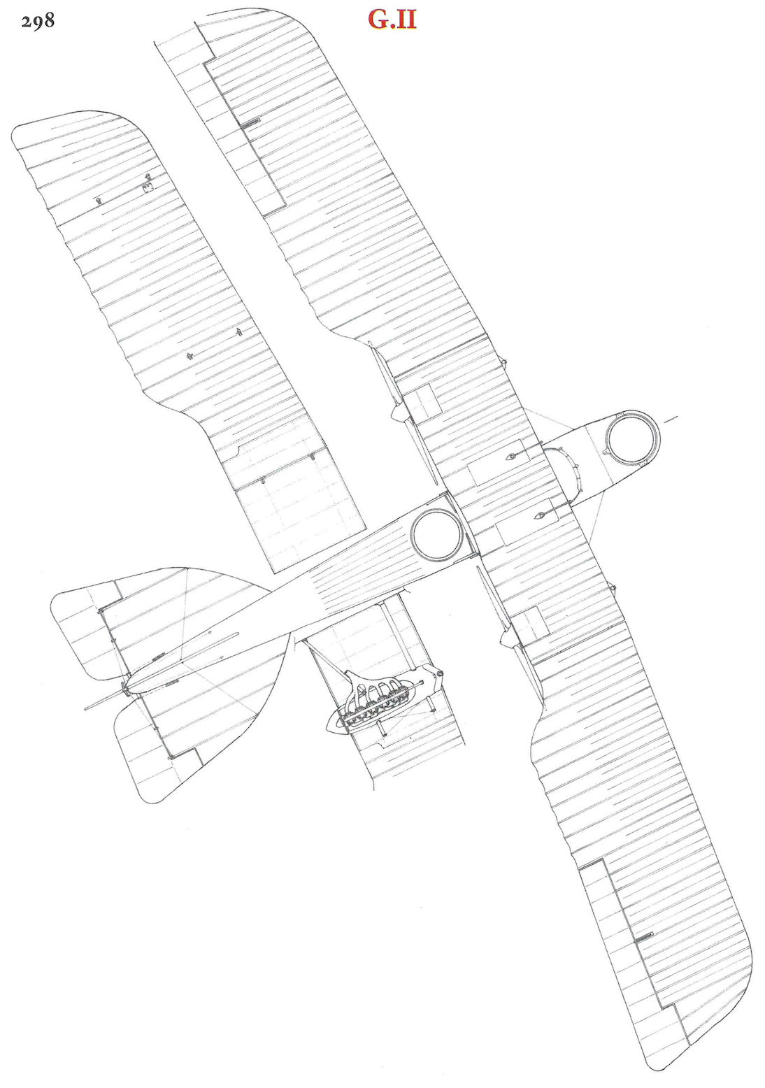
Structurally, the G III consisted of a complete central section which comprised the cockpit and "cabin" portion (where fuel tanks and some bombs were carried), the engines and the centre-section of the upper and lower wings. To this central section the mainplanes and forward and rear parts of the fuselage were bolted. The section itself was some 4 ft. by 4 ft. 3 in. in cross-section, with stout longerons and ply bulkheads, and was completely ply covered. The forward bulkhead served as an instrument board, and immediately aft of it were positioned side-by-side seats. The pilot's seat was fixed and upholstered, but that for the bombing officer was a folding steel-tube affair with webbing back-rest. Aft of the cockpit the section was "roofed" over with plywood, part of which was detachable to give access to the second main fuel tank, the first being under the seats. At each side of the passageway were racks for stowing five 10 kg. bombs each. The main bomb racks were fitted externally below the nacelle and were of tubular frames. These were readily removable, as the bomb loads were varied to suit the tactical or strategical requirements.
The forward part of the fuselage, containing the front cockpit with the bomb-release gear, was plywood covered and bolted to the main section. The aft section extended from a point level with the airscrews and was of square-section longerons and spacers with bays transversely cable braced and, except for the extreme rear end (which was ply covered to absorb tail stresses), was fabric covered. The rear cockpit was provided with a movable gun mounting, and in the raised floor was a trap door in which were fitted two celluloid windows to facilitate downward vision. A novel feature in the otherwise orthodox controls was a trimming device in the form of a winch connected to tension springs 1 m. in length introduced in the elevator linkage. Winding to the left gave tail-heavy trim; turns to the right gave the reverse trim.
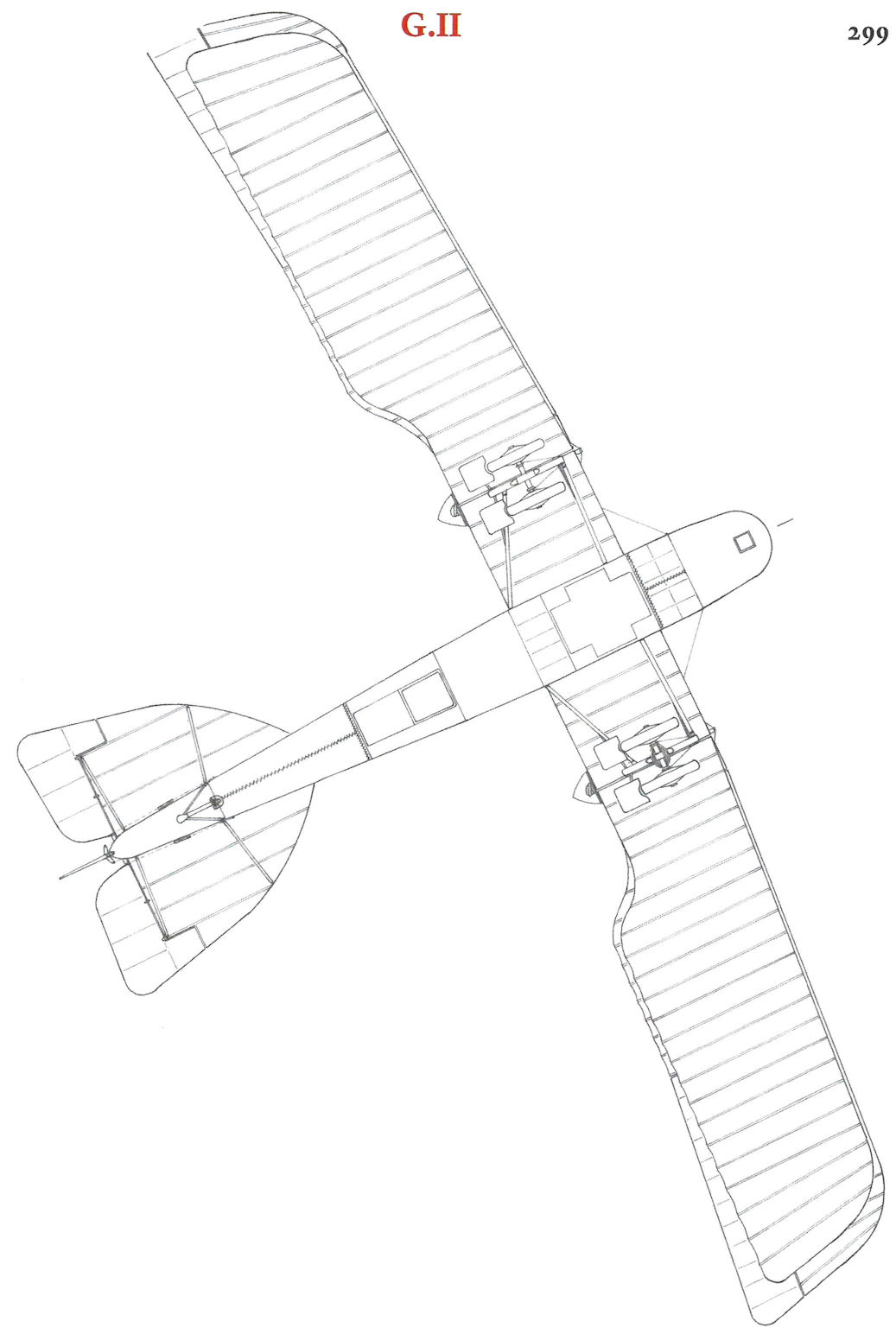
The centre-section portion of the wings was built up on 2-in.-diameter steel-tube spars braced diagonally to form an X. All main ribs were of three-ply with spruce flanges, and had false ribs interspaced on the top wing only. The upper surface of the lower centre-section was plywood surfaced, the remainder fabric. Two 260 h.p. Mercedes D IV engines with pusher airscrews and frontal car-type radiators were slung between the wings. The actual bearer struts and the connecting struts to the upper wing were of streamlined steel tube of 1/16 in. wall thickness. In front elevation these struts formed a vee, the lower end of which was attached to the tubular steel spars on the bottom wing; the upper ends were pin-jointed to the top-wing main spars, the pin being utilised to anchor the bracing cables.
Two fabric-wrapped built-up box-spars of spruce formed the basis of the outer, detachable portions of the wings and were braced with stranded cables and steel-tube compression members. The three-ply main ribs were socketed into grooved spruce flanges, and between each ran a false rib extending as far aft as the rear spar. A solid spar of near semicircular shape formed the leading-edge, while the usual wire comprised the trailing-edge member. Inboard the trailing edge was cut back to allow airscrew clearance. With the exception of the inner ends of the lower wings, which were ply-covered on the top surfaces, the remainder of the outer panels were fabric covered. The interplane struts, of somewhat massive proportions, were actually built up with a central spine of ash, and the streamlining fore and aft portions of low-quality timber.
Complete tail surfaces and ailerons were mainly of steel-tube construction, only a few wooden stringers being used in the tailplane. All the control surfaces were generously horn balanced, the rudder and aileron dances being inset, the elevators overhung. Streamlined steel tubes traced the tailplanes to the fuselage, and to these sharp steel points were welded to deter their use when manhandling the aircraft on the ground. As is apparent, the five-wheel undercarriage was a somewhat cumbersome appendage, the centre wheel being solely to prevent nosing over on landing. The main wheels were sprung with steel-spring shock absorbers ad fitted with guards to prevent stones being flung into the airscrew. The tailskid was a sturdy ash component, heavily steel shod and sprung within the fuselage.
A modified version with a compound tail assembly was also produced later; known as the G IIIa, this version was built under licence by the Daimler Works and Hanseatische Flugzcug-Werke.
TECHNICAL DATA
Description: Twin-engined long-range bomber.
Manufacturers: Flugzeubau Friedrichshafen G.m.b.H. Manzell. (Fdh.).
Sub-contractors: Hanseatische Flugzeug-Werke (93 G III and G IIIa) (Hansa.); Daimler Motoren-Gesellschaft (245 G III and G IIIa) (Daim.).
Power Plant: Two 260 h.p. Mercedes D IVa 6 cylinder in-line water-cooled engines.
Dimensions: Span, 237 m. (77 ft. 9 1/4 in.). Length, 12.8 m. (42 ft.). Area, 95 sq.m. (1,020 sq.ft.).
Weights: Empty, 2,695 kg. (5,929 lb.). Loaded, 3,930 kg. (8,646 lb.).
Performance: Maximum speed, 135 km.hr. (84.35 m.p.h.). Duration, 5 hr.
Armament: Two or three manually operated Parabellum machine-guns in nose and rear cockpits. Bomb load varied to suit tactical, or strategical, requirements, but averaged 1,500 kg. (3,300 lb.)
Friedrichshafen G IIIa
Virtually a standard G III, the G IIIa differed only in having a compound tail and less curved wingtips. The majority were built under licence by Daimler Motoren-Werke. Engines, two 260 h.p. Mercedes D IVa. For all details see G III in main text.
L.Andersson Soviet Aircraft and Aviation 1917-1941 (Putnam)
Friedrichshafen G IIIa
Together with the Gotha G V, the twin-engined Friedrichshafen G III formed the equipment of the German bomber units during the last years of the First World War. The G III normally carried a crew of three in bomber configuration, but could also be fitted out for transport of passengers. At the request of the Austro-German War Prisoner Repatriation Commission the Deutsche Luft-Reederei sent four of its Friedrichshafen G IIIa aircraft from Konigsberg to Smolensk in January-February 1920, carrying medical supplies and members of the commission. One had to discontinue the flight and landed in Poland but the other three (pilots Lang, Mohr and Polte) reached their destination.
The machine flown by Willi Polte was allowed to return in March but the other two (c/ns 202 and 282) were confiscated by the Soviet authorities and soon went into service with the RKKVF. The reason for letting Polte take off with his aircraft was that he was to carry a Soviet trade representative to Berlin. Their flight ended in Lithuania, however, when Polte had to make a forced landing after getting his fuel tanks holed by ground fire. One of the RKKVF Friedrichshafens, which were equipped to carry eight passengers, was assigned to the Aviazveno osobogo naznacheniya and later the Headquarters of Aviaeskadra No. 1 in Moscow, while the other was used in the Ukrainian and Western Military Districts. One of them (c/n 202) was flown at Khodynka during the 'Week of the Air Fleet' in June 1923.
G IIIa
Two 260hp Mercedes D IVa Span 22.6m; length 12.8m; height 4.14m; wing area 86m;
Empty weight 2,500kg; loaded weight 3,653kg
Maximum speed 145km/h; cruising speed 135km/h; landing speed 100km/h; ceiling 6,000m; endurance 5hr; range 650km
P.Grosz, G.Haddow, P.Shiemer Austro-Hungarian Army Aircraft of World War One
Friedrichshafen G.IIIa(Daim) Series 07
After the Brandenburg G.I debacle the LFT, in November 1917, requested the German air service to release sufficient Friedrichshafen G.III bombers to form a small long-range bombing force. The request was rejected because the Friedrichshafen bombers could not be spared; instead the LFT was offered, and subsequently purchased, the inferior Gotha G.IV bomber. However, to investigate the possibility of license production, the Germans released one Friedrichshafen G.IIIa airframe, less engines, to serve as a test and pattern aircraft. Upon delivery in April 1918, it was assigned the number 07.01.
The problems experienced with the Gotha G.IV series 08 bombers led the LFT to renew its request for 50 Friedrichshafen bombers. The sale was approved but a devastating fire at Friedrichshafen factory on 13-14 April 1918 nullified the order. With license production growing rapidly at Daimler and Hansa, Germany finally released 20 Friedrichshafen G.IIIa (Daim) bombers on 1 August 1918. To avoid the engine installation problems which had plagued the Gothas, the 260 hp Mercedes D.IVa engines were to be installed at the Daimler factory in Germany. The series designation assigned was 07.02 to 07.21, but none of the bombers were delivered prior to the end of the war.
Friedrichshafen G.IIIa(Daim) Series 07
Engine: 2 x 260 hp Mercedes D.IVa
Wing: Span Upper 24.00 m (78,74 ft)
Chord Upper 2.35 m (7.71 ft)
Chord Lower 2.35 m (7.71 ft)
Total Wing Area 94.9 sqm (1021 sq ft)
General: Length 12.72 m (41.73 ft)
Height 3.39 m (11.12 ft)
Empty Weight 2700 kg (5954 lb)
Loaded Weight 3935 kg (8677 lb)
Maximum Speed: 160 km/hr (99 mph)
Friedrichshafen G.IIIa(Oef) Series 54
Flars originally proposed that Lohner or UFAG manufacture the Friedrichshafen bomber, but neither company had sufficient production capacity. Consequently, Oeffag received a contract on 18 May 1918 for 50 Friedrichshafen G.IIIa bombers, regarded at the time as the most effective German bomber. Oeffag had signed a license agreement with the Friedrichshafen Flugzeugwerke on 12 May 1918. To serve as pattern aircraft, two Daimler-built Friedrichshafen G.IIIa bombers, with 250 hp Benz Bz.IV(Mar) engines installed, arrived by rail in August 1918.
Meanwhile, Oeffag found that the German construction drawings required substantial revision, delaying the assembly of the first machine, 54.01, until September 1918, at which time the first five Oeffag-built machines should have been delivered. In the event, aircraft 54.01 was scheduled for delivery in December 1918, to be followed by four production bomber in January 1919. At the war's end the contract was cancelled before a single series 54 bomber had been completed. Nor were the 20 Friedrichshafen G.IIIa(Daim) series 07 bombers, ordered from Daimler in Germany, delivered.
Friedrichshafen G.IIIa(Oef) Series 54 Specifications
(based on German specifications)
Engine: 2 x 250 hp Benz (Mar)
Wing: Span Upper 24.05 m (78.90 ft)
General: Length 12.65 m (41.50 ft)
Height 3.40 m (11.15 ft|
Empty Weight 3000 kg (6615 lb)
Loaded Weight 4500 kg (9923 lb)
Maximum Speed: 140 km/hr (87 mph)
E.Hauke, W.Schroeder, B.Totschinger Die Flugzeuge der k.u.k. Luftfahrtruppe und Seeflieger 1914-1918
01. — 010. Flugzeuge ausländischer Produktion (Самолеты иностранного производства)
07.01 Friedrichshafen G.III (Projekt)
50. Flugzeuge der Österreichischen Flugzeugfabrik A.G. (Oeffag) Wiener Neustadt
54.01 Friedrichshafen G.IIIa (Oef, geplanter Lizenzbau) 2 x Bz 250
Журнал Flight
Flight, November 8, 1917.
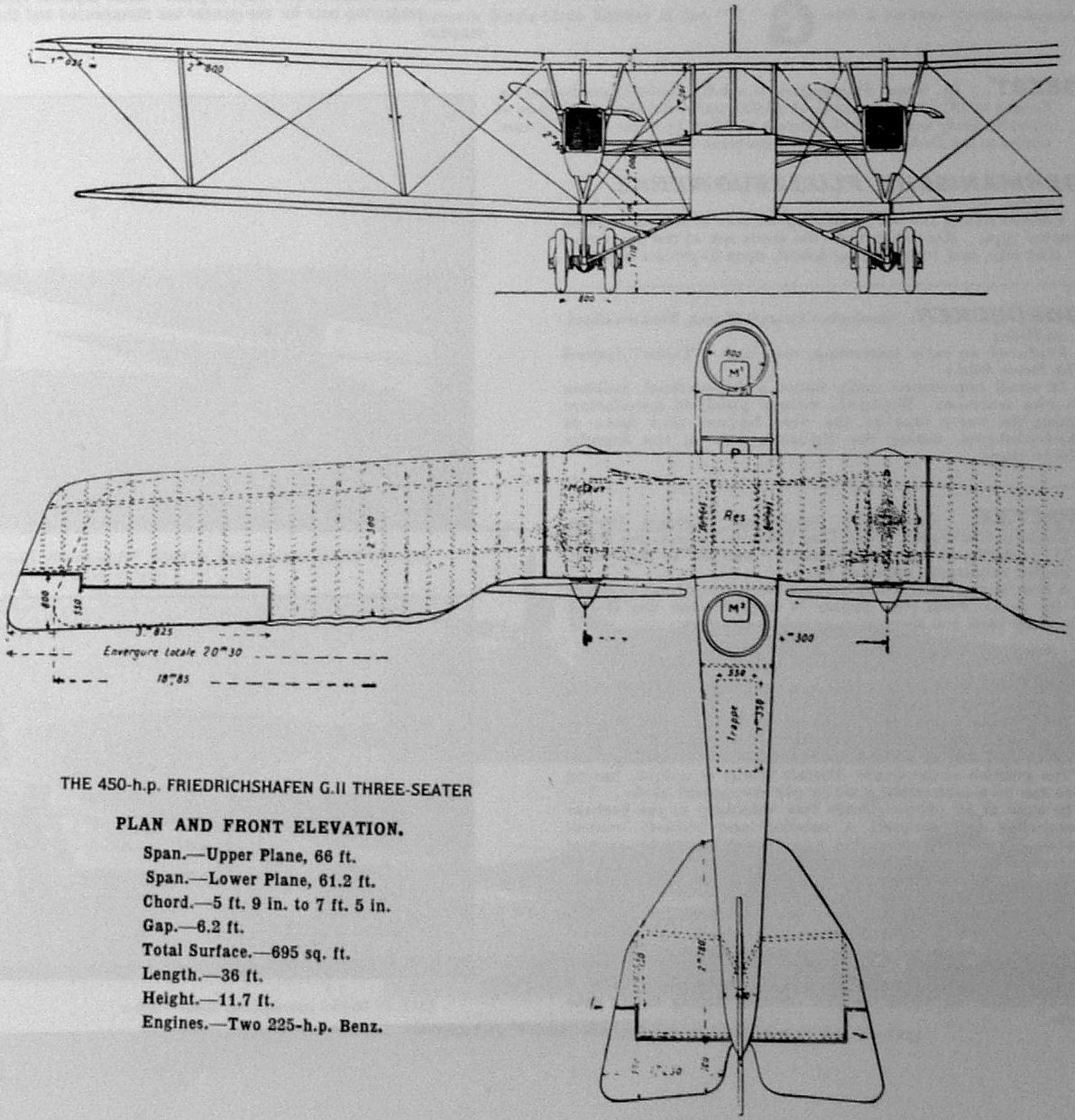
THE GERMAN F.F. BOMBER.
M. JEAN LAGORGETTE
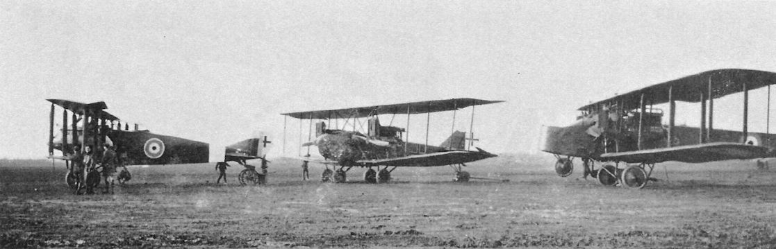
THE Fliigzeugbau Friedrichshafen have, for a considerable time past, specialised in the construction of seaplanes. For some time now they have also been making land machines, of which one type with two engines, now actually in service, is described in the following, from specimens captured recently on the French front near Verdun, and on the Macedonian front.
It is quite possible that these twin-engined machines have been used for raids on England, and on the vicinity of Paris, together with the Gothas, with which latter they have several points in common and of which, in certain respects, they are copies on a reduced scale. Their dimensions are as follows: Length about 11 metres; height, 3 m. 60 (3 m. 80 including air-screws) and 4 m. 10 to the top of the rudder). Span of upper wing, 20 m. 30; span of lower wing, 18 m. 85; the chord of the wings being about 1 m. 80 to 2 m. 30; the total wing surface is 70 sq. metres. The gap is 1 m. 95, close to the fuselage.
The wings are back-swept and set at a dihedral angle, except for the fixed central sections, which are straight on acccount of the mounting of the motors. The stagger is very small. The wing tips are raked and the ailerons have a wider chord at the tips than at the root. The trailing edges are cut away for a considerable distance in order to provide clearance for the propellers. Each motor is mounted on a framework of struts in the form of a V, and they are braced to the fuselage by struts running nearly horizontal. In addition to the motor struts, there are two pairs of interplane struts on each side, which slope outwards as shown in the front view. The overhang of the top plane is braced by diagonal wires running to the lower ends of the outer pair of interplane struts.
As distinct from the Gothas, the wing ribs are parallel to the centre line of the machine. Each of the ailerons has a forward projection near its tip, so as to partly balance it. The span of each aileron is 3 m. 80 and the chord is from 0 m. 50 to 0 m. 60. The area is about 2.3 square metres. The wings are painted green and reddish brown on the upper surface, and a clear blue on the under side.
The tail plane and elevators, the span of which is 3 m. 95 and the length 3 m. 65, resemble the irregular polygonal form of those of certain Albatros machines of 1914. The same applies to the very high rudder, in front of which is a fin of triangular shape, slightly rounded in front, and reminiscent of certain English biplanes, a feature which appears to become general on recent German machines. As on all German aeroplanes the elevators and rudder, like the ailerons, are balanced, and are constructed of steel tubing.
The fuselage is of the ordinary form, of rectangular section with the upper face horizontal. The maximum depth of the fuselage is 1 m 27, and the maximum width 1 m. 20. The cockpits in the fuselage are arranged in tandem, with sufficient space at the sides for changing places. In the nose is the gunner's cockpit, with a circular gun-ring. Behind him is the pilot's seat. Behind this again is the main petrol tank, which is o m. 90 in width, and on each side of this are the bomb racks, placed longitudinally. In the rear cockpit, which is occupied by a gunner, there is a circular gun-ring, similar to that employed in the front cockpit, and in addition there is in the floor a trap door, raised by means of a lever and cable, through which the gunner can fire in a rearward and downward direction by kneeling on the footboards. The front of the fuselage is covered with 3-ply, the rear with fabric. Behind the rear gunner, the fuselage is made detachable by means of four clips and bolts, so that the rear portion, with the tail planes, can be detached from the front part for ease in transport and storing.
The under-carriage differs considerably from that of other German biplanes. Under each motor there is a pair of wheels of 965 mm. diameter on a common axle and having a track of 0 m. 80. They are sprung by means of rubber shock-absorbers from a short skid, which is streamlined. The front and rear of these skids are connected to the lower plane by a strut sloping backwards to the base of each of the two V's which support the engines, and by a strut to the fuselage, placed at a very considerable slope.
The engines are six-cylinder Benz. No. 22799 gives 226 h.p. at 1,410 r.p.m., No. 25344 gives 221 h.p. at 1,400 r.p.m. Each of the engines is enclosed in a little boat-shaped nacelle terminating at the rear in a streamlined piece fitted over the propeller-boss. In the nose of the nacelle is mounted the radiator. The air-screws, which are marked "Imperial," have a diameter of 2 m. 90. The various tanks contain a total of about 550 litres of petrol. The oil tanks are placed under the radiators and extend a short distance to the rear.
In addition to the machine guns, the F.F. biplane appears to carry 12 explosive bombs and a few incendiary bombs. The number appears to vary. The total weight of the machine empty is 2,200 kilogs., the useful load 520 kilogs., and the weight of fuel 432 kilogs., giving a total weight of 3,152 kilogs., which works out at nearly 45 kilogs. per square metre, which is a very heavy loading, and 7 kilogs. per h.p. The machine carries fuel for four hours.
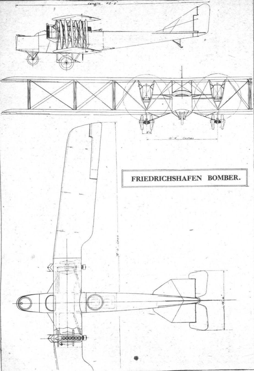
Flight, July 4, 1918.
REPORT ON THE FRIEDRICHSHAFEN BOMBER.
[Issued by the Technical Department (Aircraft Proiuction), Ministry of Munitions.]
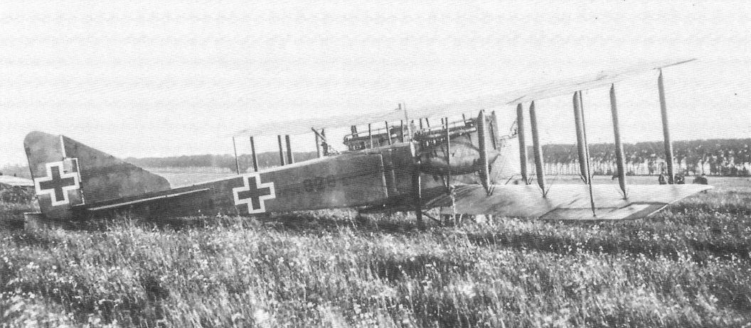
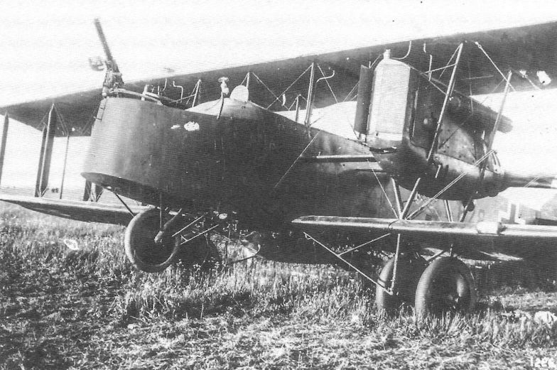
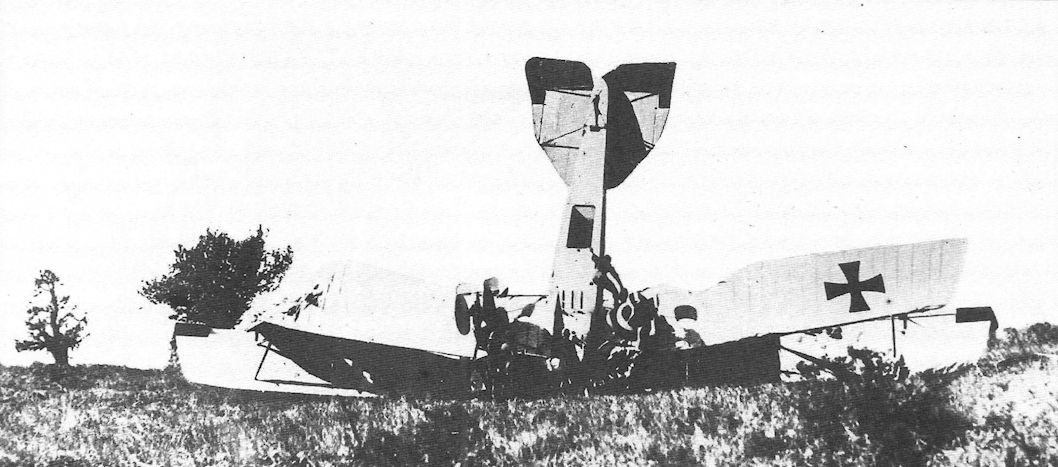
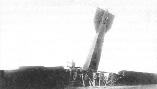
THIS machine, which bears the mark F.D.H. G.3. 326/17, was brought down by anti-aircraft fire at Isbergues on the night of the 16th February. A shell made a direct hit on the right-hand engine at a height of 8,000 to 9,000 ft., after which the machine covered about six miles and made a fairly good landing.
Various parts of the structure bear different dates, that on the tail being 14/1/18. The main spars are branded with a small crown and the letters Z.A.K. The following is painted on the side of the body :-
Leergewicht (weight empty), 2,695 kilogrammes = 5.929 lbs.
Nutzlast (useful load), 1,235 kilogammes = 2,717 lbs.
Zulassiges Gesamtgewicht (permissible total weight), 3.930 kilogrammes = 8,646 lbs.
Crew.
This machine carried its full complement of four persons, namely, pilot, fore-gunner, after-gunner, and bomber. It is known, however, that the number of crew varies considerably, as some machines of this type have only carried two persons. The accommodation is so arranged that the personnel can easily change places, all the cockpits being inter-communicating.
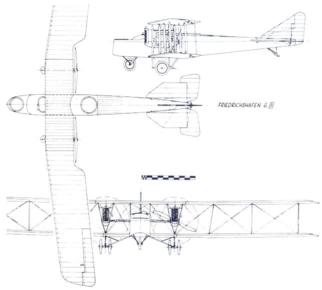
General Description.
The general design of the machine is shown in the attached drawing, which gives plan and front and side elevations.
The principal dimensions are as follows :-
Span 78 ft.
Maximum chord 7 ft. 8 ins.
Gap 7 ft.
Dihedral angle in
the vertical
plane 1 1/2#
Dihedral angle in
the horizontal
plane 6#
Total area of
main planes 934.4 sq.ft.
Area of upper
main planes
without flap 480 "
Area of lower
main planes
without flap 454.4 "
Load per sq. ft. 9.24 lbs.
Weight per h.p. 16.6 lbs.
Area of flap of
upper wing 21.6 sq. ft.
Balance area 1.8 sq.ft.
Area of flap on
lower wing 1.6 "
Balance area 1.56 "
Total area of fixed
tail planes 57.6 "
Total area of elevators
32 "
Balance area of
one elevator 1.7 "
Area of fin 20 "
Area of rudder 19.2 "
Balance area of
rudder 3 "
Maximum cross
section of body 19.2 "
Horizontal area
of body 133 "
Vertical area of
body 131.2 "
Length overall 42 ft.
The machine is built up upon a central section, to which are attached the forward and rearward portions of the fuselage and the main planes. This central section comprises the main cell or cabin of the body containing the tanks bombs, &c. It also embraces the engines and the central portion of the upper and lower planes. The latter, together with the engine struts, are largely built up of steel tube, as is also the landing gear.
The central portion of the body, which measures 4 ft. across by 4 ft. 3 ins. in height, consists of a box formation made of ply wood, strengthened by longerons and diagonals, and transversely stiffened by ply-wood bulkheads. The bulkhead furthest forward acts as an instrument board, behind which are side by side the seats of the pilot and his assistant. The former has a fixed upholstered seat, whilst that of the latter is folding, consisting of a light steel tubular framework with a webbing back-rest.
Underneath these two seats is the lower main petrol tank. Behind this cockpit the body is roofed in with ply wood, the rear part of which roofing is detachable so as to give access to the second main petrol tank, which is at the rear end of the main body section. By this means a small cabin or covered passage-way is provided, at each side of which are the racks for the smaller bombs.
Central Portion of Wings.
The central and non-detachable portion of the upper plane has a span of 19 ft. 5 ins., whilst at each side of the nacelle the lower plane fixed portion measures 7 ft. 8 ins. The main wing spars in this central portion are of steel tube, roughly 2 ins. in diameter, with a wall thickness of 1/16 in.
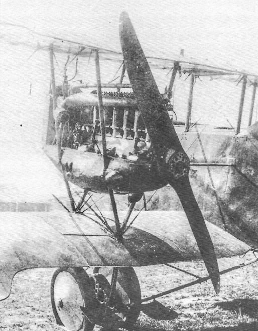
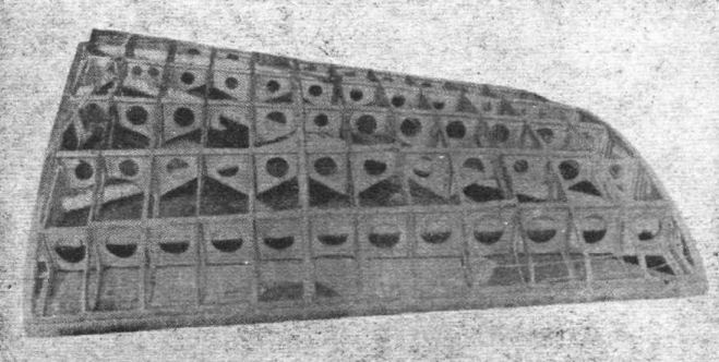
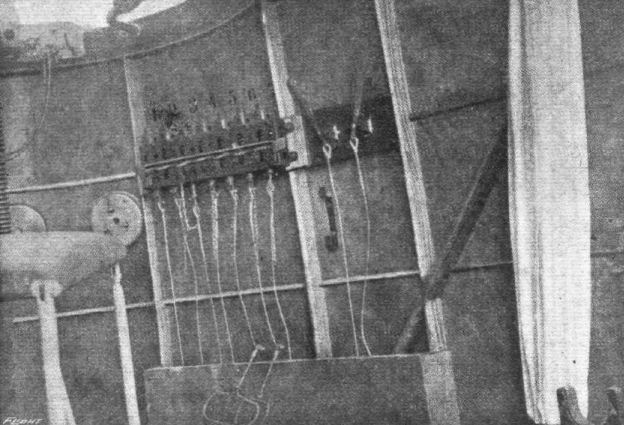
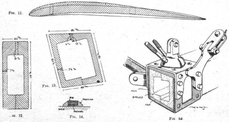
As shown in the photograph Fig. 1, these spars are braced by steel tubes arranged in the form of an X, the manner in which the bracing tubes are attached to the main spars being shown in the sketch Fig. 2.
The lugs are built up by welding, and are pinned and riveted in position, the joint being of the plain knuckle type.
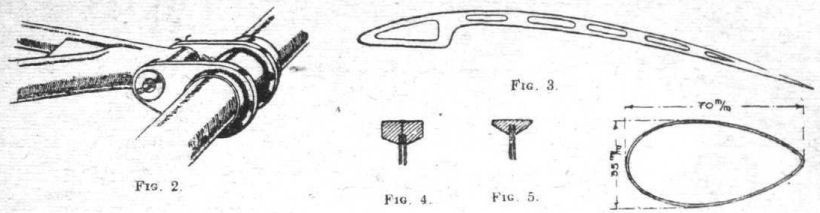
The upper-surface of the lower plane is, so far as the central section is concerned, covered in with three-ply wood. In this portion the main ribs are of three-ply, with spruce flanges. Between each main rib is a cut-away rib, the design of which is shown in the sketch Fig. 3. This, unlike the main ribs, is one piece of wood, and not built up. For the greater part of its length it applies to the top surface only, being cut away to pass clear of the-cross bracing tubes.
As shown in the photograph Fig. 1, the plane is further stiffened with transverse members consisting of three-ply panels between each rib strengthened by grooved pieces top and bottom. The latter are attached as shown in the sketch Fig. 4, and the attachment of the flanges of the main ribs is shown in Fig. 5.
The central section of the upper main plane is in one piece, and is covered top and bottom with fabric. In order to facilitate the removal of the engines, detachable panels measuring 1 ft. 11 1/2 ins. long by 1 ft. 8 ins. deep are let into the trailing edge immediately over the engine bearers. These panels are socketted in front, and at the rear are joined up at the trailing edge with U-section sheet steel clips and bolts.
The struts which connect the top of the nacelle to the upper plane are tubular and of streamline section, as are also the engine bearer struts. A section of one of the latter is given in Fig. 6. The thickness of the wall is one-sixteenth of an inch.
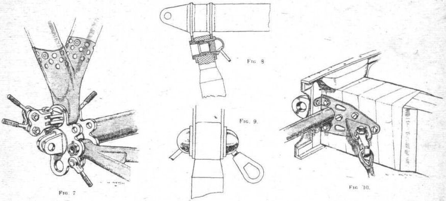
The method of attaching the lower end of the engine struts to the tubular steel spars is shown in the sketch Fig. 7, from which it will be seen that a welded Y socket is used and secured by a pin joint, the ends of the pin acting as anchorages for the attachment of the bracing wires.
This sketch also shows the lugs which respectively support the detachable portion of the main planes and the vertical strut of the landing chassis. The engine bearer struts are pushed into the Y socket and pinned in position, the pins being afterwards brazed into the socket. At their upper ends the engine struts are fixed to the top plane spars with pin joints, as shown in Figs. 8 and 9, the attachment differing according to the number of wire bracings that are to be taken to each joint.
Construction of Wings.
The detachable portions of the wings are fixed to the centre section by pin joints, one part of which is shown in Fig. 7, the male portion being represented in Fig. 10. The chord of the wing in the line of flight varies from approximately 7 ft. 8 ins. to 7 ft, 5 ins., and the wing section is shown shaded in Fig. 11. In order to provide a basis of comparison the R.A.F. 14 wing section is superimposed and drawn to the same scale.
The main spars are placed one metre apart, the front spar being 272 mm. in the rear of the leading edge. Both spars are of the built-up box type, as shown in Figs. 12 and 13. The former is the leading spar and the latter the rear spar. These spars are of spruce, and each half is furnished with several splices, so that the greatest single length of timber in them is not more than 14 ft. The splices, which occur in each half alternately, are of the plain bevel type about 15-ins. long and wrapped with fabric. A fabric wrapping is also applied at short intervals along the spar.
Internal cross bracing between the main spars is afforded by steel tube cross members and cables attached as shown in the sketch Fig. 10.
The main spar joint consists of a steel plate 19 mm. thick embedded in the spar end and held in position by 5 bolts, which pass through a strapping plate surrounding the end of the spar. This plate also carries the attachment for the bracing cable, and is furnished with a spigot which locates the bracing tube. It w 11 be seen that at this point the spar is provided with tapered packing pieces of hard wood glued and held in position by fabric wrapping.
The main ribs are placed 360 mm. apart. Between them are auxiliary formers, consisting of strips of wood 20 mm. x 10 mm. thick, which run from the leading edge to the rear spar. The main ribs consist of ply wood webs socketted into grooved spruce flanges, which are tapered off as shown in Fig. 5, except where they are met by a longitudinal stringer. The leading edge is solid wood moulded to a semi-circular section of approximately 65 mm. diameter. Where the rib web abuts against it, packing pieces are glued each side. Between the main spars the web of the rib is divided by three vertical strips into four panels, and in each of these it is perforated, leaving an edge all round about 72 mm. wide.
As shown in Fig. 10, the.upper flange of the main ribs is carried clear of the leading spar by means of packing pieces. In the case of the rear spar, packing pieces are also used under the rib flange, as shown in Fig. 14.
The lower main planes for a width of about 2 ft. 3 ins. at their inner end are covered as to their top surface with three-ply wood.
The interplane struts are attached to the main spars by joints of the type shown in Fig 15. This, it will be seen, follows the typical German practice of partially universal jointed mountings for the cable attachments. At the points of attachment of these strut joints, suitably tapered packing pieces of hard wood surround the spars, which at these points arc also wrapped with fabric.
Struts.
Outside of the centre section the interplane struts are of wood built up, as shown in the section Fig. 16, of five separate pieces. The curved portions are of timber which has not yet been identified, but is apparently of poor quality. The cross web is of ash. The strut is wrapped at frequent intervals with strips of fabric and is fitted with a socket joint of the type shown in Fig. 17. The outer pair of struts are of smaller section than the main struts, but are built up in a similar manner. Their section is 125 mm. x 40 mm.
Ailerons.
The framework is principally of welded steel tube wrapped with fabric.
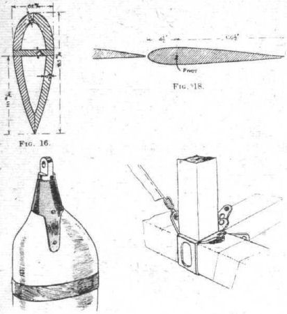
A notable point is the thick section of the leading edge of the balanced portion, as shown in Fig. 18.
Fin and Fixed Tail-planes.
The framework of these is steel tube, and in the case of the tail-planes wooden stringers running fore and aft are arranged at intervals. The tail-planes are supported by diagonal steel tubes of streamline section, on the under side of which sharp steel points are welded to prevent these stays being used for lifting purposes.
Elevators and Rudders.
The framework in each case is of steel tube, the main tube being 35 mm. in diameter and the remainder 15 mm.
Bracing.
Throughout the wings, both internally and externally, the bracing is by means of multistrand steel cable.
Fuselage (Rear Portion).
At the after-gunner's cockpit the section of the fuselage has a rounded top, which is gradually smoothed down into flat. The section, for the greater part of the length, is rectangular, and the frame is built up in the usual manner with square section longerons and verticals, the joints being arranged as shown in Fig. 19. The cross bracing wires along the sides, top, bottom, and diagonal are of steel piano wire and are covered with strips of fabric, as shown in this sketch, where they lie adjacent to the fabric fuselage covering.
The vertical and horizontal compression members are located by spigots. The joint consists of a plate which completely surrounds the longerons, its two ends being riveted together to form a diagonal bracing strip. For the last few feet at the tail the fuselage is covered with thin three-ply.
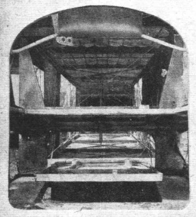
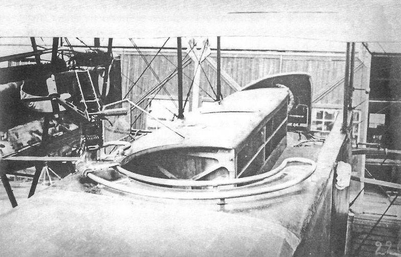
Fig, 20 is a view looking down the rear portion of the fuselage. The fuselage is covered with fabric, which is held in position by a lacing underneath, and is consequently bodily removable.
The floor of the after-gunner's cockpit is elevated above the bottom of the fuselage. Immediately underneath this cockpit is a large trap door, shown in the photograph No. 20, and also by dotted lines in the plan view of the aeroplane. This is hinged at its rearward end and furnished with two large celluloid windows. It is held in its "up" position by a long spring and a snap clip. No means could be found by which it could be fixed in its closed position. As footsteps are provided for all the cockpits, this trapdoor is evidently not intended for ingress and egress. It could be employed in connection with a machine gun firing backwards, as in the Gotha, but no machine gun mounting was fixed in this machine for this purpose.
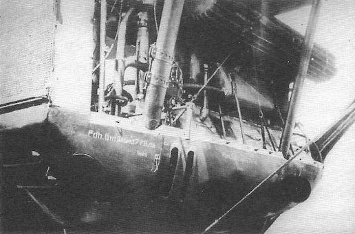
The rear portion of the fuselage is attached to the centre section of the body by a clip at each corner. This is shown in Fig. 21. The rear portion carries a male lug, shown in Fig. 50, which engages with the two eyes, and is held in position by a three-eighths bolt. Four other bolts in tension pass through the sheet metal clip, as shown in the sketch. In each case the lugs are furnished with sheet steel extensions which, as shown in the sketch Fig. 21, are sunk flush into the top and bottom surfaces of the fuselage longerons and are there held with three bolts. The corner joint is welded sheet steel, and there is an additional sheet steel joint which serves the secondary purpose of providing an anchorage for the bracing wires. As this fuselage joint is level with the plane of rotation of the propellers, it is armoured both on the nacelle and on the rear portion of the fuselage with a hinged covering of stout sheet steel lined with felt. A plate of armour a foot wide also extends down each side of the nacelle at this point.
(To be continued.)
Flight, July 11, 1918.
REPORT ON THE FRIEDRICHSHAFEN BOMBER.
[Issued by the Technical Department (Aircraft Production), Ministry of Munitions.]
(Continued from page 741.)
Forward Cockpit.
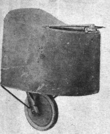
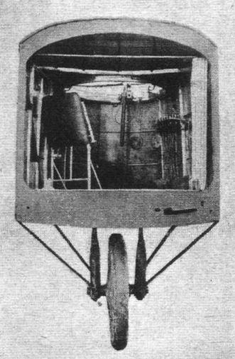
THIS is attached to the main body by four bolts with clips similar to those just described. It consists of a light wooden framework, covered throughout by three-ply. Two views of this portion of the machine are given in the photographs Figs. 22 and 23. This cockpit can be divided off from the main cockpit by means of a fabric curtain. Its occupant is provided with the folding seat, as shown, and manages a gun and the bomb dropping gear.
Engine Mounting.
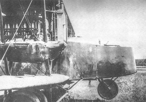
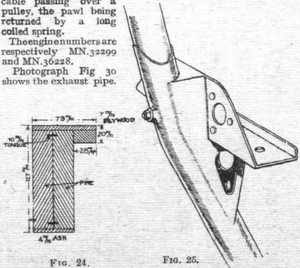
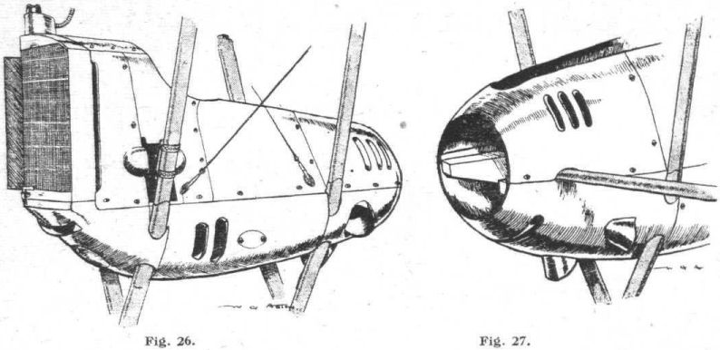
The engine bearers have the section shown in Fig. 24, and are each built up of two pieces of pine united by tongues. On their top surface they are faced with ply wood and at the bottom with ash. A strip of ash applied to the upper outer corner of the bearer gives it an "L" section, and has screwed into it the threaded sockets for the set screws of the lower part of the engine fairing. The engine bearers taper sharply at each end. They are mounted on the "V" struts by means of acetylene welded brackets, constructed as shown in sketch, Fig. 25. These, it will be seen, are of box form, and form a line round the streamline tube.
The engine cowling is a particularly fine piece of work, and two views are given in sketches 26 and 27. The lower portion is attached to the engine bearers by set screws, but the upper part is readily detachable, being furnished with turn buttons. This cowling allows the cylinders of the engine to be exposed to the air. A large scoop is placed in front, so as to permit a free flow of air over the bottom and sides of the crank chamber, whilst at the rear three large trumpet shaped cowls are provided so that a draught of air is forced against the crankcase in the neighbourhood of the carburettor air intake. In the rear the fairing abuts against the propeller nave, whilst in front it is attached to the radiator. It will be noticed that at each side of the radiator are narrow air scoops, the object of which is to promote a draught past the oil tank and front cylinder heads.
Engines.
The motors are the standard 260 h.p. Mercedes with six cylinders in line. Full details of this engine have been published, and it is only, therefore, necessary to notice one or two points in connection with the installation.
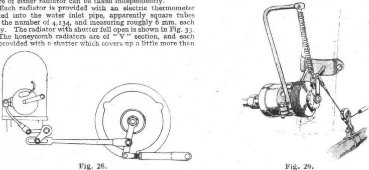
A new departure is the interconnection of the throttle and ignition advance controls. This is carried out in the manner illustrated diagrammatically in Fig. 28. It will be seen that a considerable movement of the throttle can be made independently of the ignition advance. In the Mercedes carburettor the throttle is so arranged that it cannot be fully opened near the ground without providing too weak a mixture, and it is thought possible that the full ignition advance is not obtained until this critical opening is reached.
On several German bombing aeroplanes grease pumps for lubricating the water pump spindle have been found. Fig. 29 shows the design as fitted to the Friedrichshafen. It consists of a ratchet and pawl operated grease pump, secured by a bracket to one of the engine struts, and worked from the pilot's cockpit by a lever, and a stranded steel cable passing over a pulley, the pawl being returned by a long coiled spring.
The engine numbers are respectively MN.32299 and MN.36228.
Photograph Fig 30 shows the exhaust pipe. This is of new design, although it incorporates the well-known expansion joints attached to the flanges. It will be seen that it is fitted with what amounts to a rudimentary silencer, whereas in previous machines of a similar type to the Friedrichshafen an open-ended exhaust pipe was used.
Radiators.
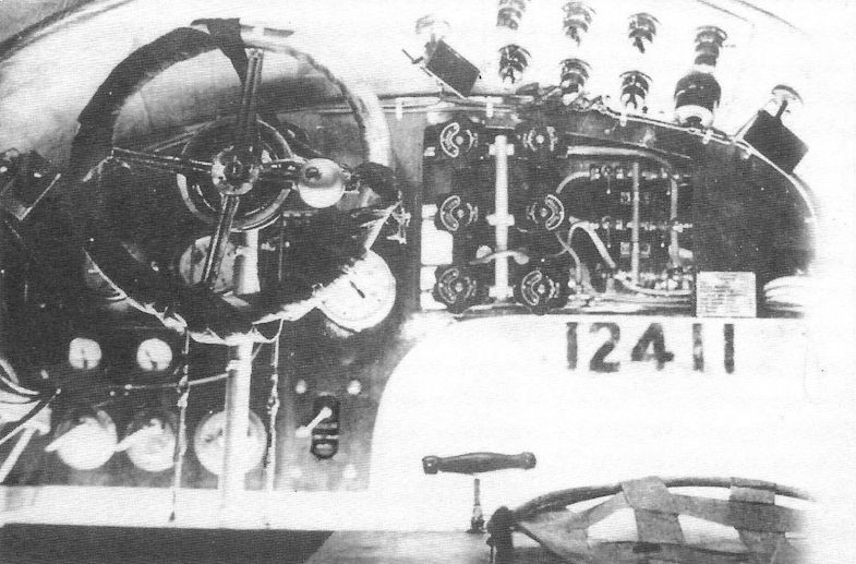
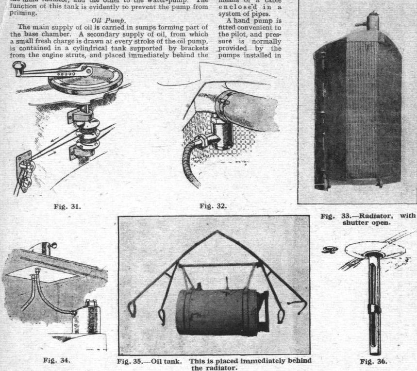
Each radiator is provided with an electric thermometer fitted into the water inlet pipe, as shown in the sketch, Fig. 32, these thermometers being wired up to a dial on the dashboard, which is furnished with a switch, so that the temperature of either radiator can be taken independently.
Each radiator is provided with an electric thermometer fitted into the water inlet pipe, apparently square tubes to the number of 4,134, and measuring roughly 6 mm. each way. The radiator with shutter full open is shown in Fig. 33.
The honeycomb radiators are of "V" section, and each is provided with a shutter which covers up a little more than a third of the cooling surface. This shutter is fitted with a stop, so that when fully opened it lies in the line of flight of the aeroplane. It is opened or closed according to circumstances by the gear, shown in the sketch, Fig. 31, of which the handle is mounted on the roof of the nacelle, immediately behind the pilot's seat. Three positions are provided for the handle, which operates the two shutters simultaneously by means of return cables.
Immediately above the main radiator, and let into the upper main plane between the front spar and the leading edge, is a small auxiliary tank, illustrated in Fig. 34. This is furnished with a trumpet shaped vent in the direction of the line of flight, and is furnished with two outlets, one to the head of the main radiator, and the other to the water-pump. The function of this tank is evidently to prevent the pump from priming.
Oil Pump.
The main supply of oil is carried in sumps forming part of the base chamber. A secondary supply of oil, from which a small fresh charge is drawn at every stroke of the oil pump, is contained in a cylindrical tank supported by brackets from the engine struts, and placed immediately behind the radiator. This tank is shown in photograph Fig. 35, and has a capacity of 25 litres = 5 1/2 gallons. Each tank is furnished with a glass level, which is visible from the pilot's seat.
Petrol Tanks.
The two main tanks, which are placed, one under the pilot's seat and the other at the top rear end of the nacelle, contain 270 litres = 59 1/2 gallons each, and are made of brass. Each is provided with a Maximall level indicator, which employs the principle of a float operating a dial by means of a cable enclosed in a system of pipes.
A hand pump is fitted convenient to the pilot, and pressure is normally provided by the pumps installed in each engine. An auxiliary tank, holding approximately 13 gallons, is concealed in the upper main plane, not immediately over the nacelle, but a little to the left side. This auxiliary tank is fitted with a level, as shown in Fig. 36, which is visible from the cockpit. The auxiliary tank appears to be used only for starting purposes. It is covered with a sheet of fabric held in position by "patent fasteners." A photograph is given in Fig. 37.
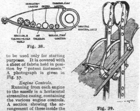
Engine Controls.
Running from each engine to the nacelle is a horizontal streamline casing, containing the various engine controls. A section showing the arrangement of these inside the fairing is given in the sketch. Fig. 38. The leading edge of the streamline casing consists of a steel tube, to which are welded narrow steel strip brackets, to the rear end of which are bolted thinner strips which are hinged in front to the tube. The whole is then enclosed in a sheet aluminium fairing.
Through the leading tube passes the throttle control rod for each engine, the two throttles being worked either together or independently by the ratchet levers, shown in Fig. 39. These are mounted on a shelf convenient to the pilot's left hand. This control requires a considerable number of bell cranks and countershafts, but was noticeably free from backlash. The throttle is opened by the pilot pulling the levers towards him.
On the dashboard are two revolution counters and two air pressure indicators. The metal parts of these dials are painted red for the left engine and green for the right, and the same colouring applies to the magneto switches, one of which contains a master switch which applies to both magnetos on both engines.
Piping.
The various systems of piping are distinguished by being painted different colours, thus the petrol pipes are while, arrows being also painted on them to show the direction of flow; air pressure pipes are blue, and pipes for cable controls grey.
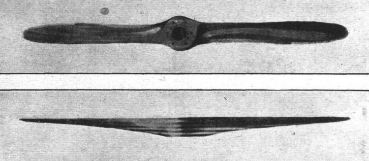
Propeller.
The propellers are made by the Luckenwalde Propellerwerke, Niendorf, Each propeller is 3.08 metres in diameter and is made of nine laminations, which are alternately walnut and ash, except one, which appears to be of maple. Photographs, Figs. 40 and 41, show the propeller, which has the last 20 ins, of its blade edged with brass. The pitch is approximately 1.8 metres and the maximum width of the blade 220 mm.
(To be concluded.)
Flight, July 18, 1918.
REPORT ON THE FRIEDRICHSHAFEN BOMBER.
[Issued by the Technical Department (Aircraft Production). Ministry of Munitions.]
(Concluded from page 773.)
Controls.
ONLY one set of control gears is fitted; but, as pointed out, the seating accommodation is so arranged that any of the crew can take charge if, and when, necessary.
The elevator and aileron control is shown in sketch Fig. 42. It consists of a tubular steel pillar mounted on a cranked cross bar at its foot. The ailerons are worked by cables passing over a drum on the wheel, whence they descend through fibre guides on the cross bar to another wheel mounted on a countershaft below, from which they are taken along inside the leading edge of the lower wing and finally over pulleys up to the aileron levers on the top plane. The latter are partially concealed in slots let into the trailing edge of the wing. The upper and lower ailerons are connected by means of pin jointed tubular steel struts of streamline section.
It will be observed from Fig. 42 that a locking device whereby the elevator control can be fixed in any desired position is fitted, and consists of a slotted link which can be clamped by a butterfly nut to the control lever. This link is hinged to a small bracket attached to the panel below the pilot's seat.
Fig. 43 shows the rudder control, from which cables are taken over pulleys and through housings in the nacelle and finally to the end of the fuselage. The cranked rudder bar is of light steel tube, and is arranged to be placed in the pivot box in either of two positions. It is furnished with light steel tubular hoops which act as heel rests and are adjustable. A locking clip is fitted on the floor of the cockpit so that the rudder can be fixed in its neutral position.
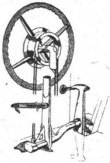
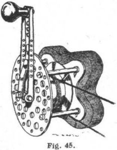
A novel type of trimming gear is an interesting item of the control. Movement of the elevator control from the normal upright position of the stick is made against the tension of one of two springs which can be alternately extended and relaxed by means of a winch connected to them, as shown in the diagram, Fig. 44. Normally these springs tend to bring the control stick back to a central position, in which the elevator lies flat, but if one of the springs is tensioned by winding up the winch in a clockwise direction, the position to which he stick will tend to come when released will be such as set the elevator at a positive angle. This winch gear, which is illustrated in Fig. 45, is mounted on the right-hand side of the nacelle, and is therefore under the command of the pilot's companion.
The crank is furnished with a locking pawl, which engages with a ring of small holes bored in the plate of the winch. The steel springs used in conjunction with this apparatus are some 3 ft. long and about f in. in diameter. The inscription behind the winch reads:
Nose heavy - Right wind.
Tail heavy - Left wind.
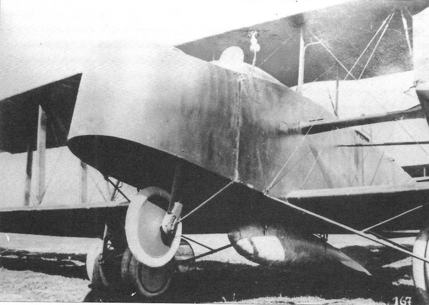
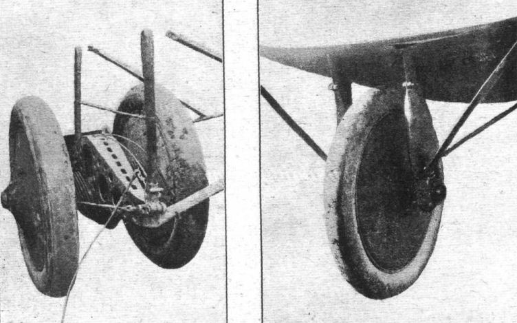
Landing Gear.
As might be expected, the landing gear on this machine is of massive proportions. Two vertical streamline section wood-filled tubes descend from the centre section wing spars, immediately under the engine, to a bridge piece or hollow girder made of welded steel. This is shown in the photograph Fig. 46. Through an oval hole in this girder a short axle carries two 965 mm. X 150 mm. wheels (38 ins. x 6 ins.). These work up and down against the tension of a bundle of steel springs about 1/2 in. in diameter and made of wire approximately 1/16 in. thick. The steel girder is extensively pierced for lightness, and the edges of the holes are swaged inwards. The axle is prevented from moving sideways by plates, and is provided with short steel cables which act as radius rods and connect it to the front of the girder. The whole of the box girder is covered in with a detachable bag of fabric, which extends up to the small cross bar mounted immediately above the girder.
Mudguards are provided behind each landing wheel for the purpose of preventing any mud or stones dislodged by the wheels from coming in contact with the propellers.
From the front and rear of the box girder streamline tubes are taken to the ends of the main wing spars, where they abut against the nacelle, and these diagonals are further braced with streamline steel tubes. Both the vertical and diagonal tubes are held in split sockets so as to be easily replaceable if damaged.
In addition to the four main landing wheels, a fifth is mounted under the nose of the fuselage, as shown in the photograph Fig. 47. This wheel is 760 mm. x 100 mm. (30 ins. x 4 ins.). It is mounted on a short tubular axle, which is capable of sliding up and down slots in its forks against a strong coil spring, and it is also capable of a certain amount of lateral movement along its axle, also against the action of two small coil springs.
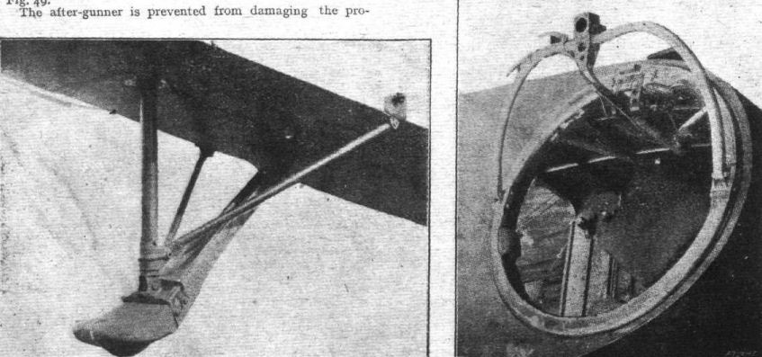
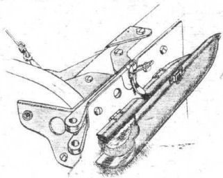
The tail portion of the fuselage is protected by a fixed skid made of wood but shod with a steel sole. This is arranged, as shown in photograph Fig. 48, and is fitted with a small coil spring contained inside the fuselage.
The whole of the wiring system on the machine is very neatly carried out. There are three main systems; firstly, the ignition wiring, which is contained for the most part in tubes of glazed and woven fabric, secondly, the heating system, for which the wires are carried in flexible metal conduits, and thirdly, the lighting system, in which a thin celluloid protective tubing is used. Wires are run from the nacelle along the leading edge of the upper planes to points level with the outermost strut. Here they terminate in a plug fitting placed behind a hinged panel. Apparently lamps are intended to be served by this circuit. Immediately in front of the pilot's seat a universally jointed lamp bracket is Fig. 45. mounted on the outside of the nacelle. The exact purpose of this lamp is not known, as it could not illuminate any instruments.
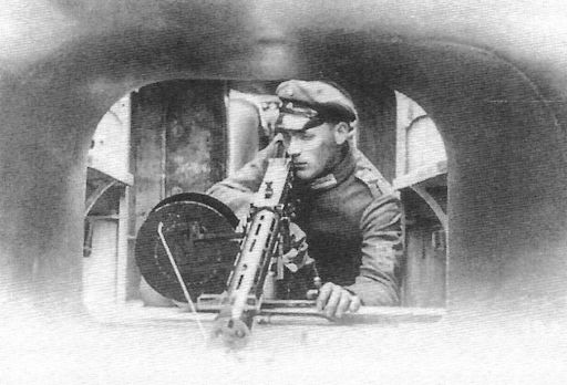
Armament.
Both the forward and rear cockpits are furnished with swivel gun mounts carrying Parabellum machine guns. These mounts consist of built-up laminated-weed turntables, working on small rollers, and carry a U-shaped tubular arm for elevation. This arm is hinged to a plunger red working through a cross head, and arranged so that the arm is normally pulled down flat on the turntable by a coil spring. The plunger can be locked in any of a series of positions by means of a bolt operated by a hand-lever through a Bowden wire. A second lever allows the turntable to be locked at any desired point. A perforated sheet-metal shield protects the cross head and spring. Small shoulder pads are fixed on the turntables, of which that in the forward cockpit has a diameter of 2 ft. 10 1/2 ins., whilst in the rear the diameter is 3 ft- of in.
A photograph of the forward gun mounting is given in Fig. 49.
The after-gunner is prevented from damaging the propellers by two wire netting screens supported by tubular steel brackets, placed on either side of his cockpit. These are sketched in Fig. 50.
In addition to these two guns, provision is made for mounting a third in front of, and to the right of, the pilot's cockpit, where it could be managed by his companion. For this purpose a clip is provided immediately under the coaming of the nacelle, and the handle of this protrudes through a slot in the dashboard. The clip works on the eccentric principle, and appears to be self-locking. Its construction is shown in detail in Fig. 51.
A rack for Verey lights is mounted on the outside of the nacelle convenient to the pilot's companion.
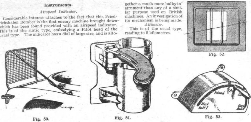
Instruments.
Airspeed Indicator.
Considerable interest attaches to the fact that this Friedrichshafen Bomber is the first enemy machine brought down which has been found provided with an airspeed indicator. This is of the static type, embodying a Pitot head of the unsual type. The indicator has a dial of large size, and is altogether a much more bulky instrument than any of a similar purpose used on British machines. An investigation of its mechanism is being made.
Altimeter.
This is of the usual type, reading to 8 kilometres.
Level Indicator.
This is a somewhat crudely made device, employing two liquid levels, as indicated in the diagrammatic sketch Fig. 52. It will be seen that the reading gives the pilot an exaggerated idea of the angle of roll. The glass tubes are sealed up, and contain a dark blue liquid. One side of the dial is engraved Hangt links (Hangs left), the other Hangt rechts (Hangs right). The manufacturer is Arno Weisse, Berlin.
Revolution Counters.
The dials give readings from 300 to 1,600 r.p.m. The sector between 1,300 and 1,500 is painted black, and these figures are marked with luminous compound, as also is the indicating hand. The manufacturer is Wilhelm Morell, Leipsig.
Air Pressure Gauges.
These read from o to 0.5 kilogrammes per square centimetre. There is a red mark against the figure 0.25 kg. The manufacturer is Maximall Apparate Fabrik, Berlin.
Electric Thermometer Dial.
This dashboard instrument consists of a box-type meter, the dial reading from 0 to 100 C. The figures 0 and 75 are accentuated by red marks. A switch at the side of the box, having positions marked 1 and 2, allows the temperature of either radiator to be read.
Petrol Level Indicators.
These are of the Maximall type, and employ a float immersed in a tubular guide in the tank. This float communicates its motion to a finger working over a circular dial, by means of a thin cord passing over pulleys. These are encased in pipes which are under the same pressure as the tank.
Electric Heating Rheostat.
This is illustrated in Fig. 53. It is marked Aus (off), Schwach (weak), Stark (strong). There are two separate resistance coils, enabling the rheostat also to perform the function of a change-over switch.
Wireless.
The machine is internally wired for wireless, and the left-hand engine is provided with a pulley and clutch for driving the dynamo. Reference to Fig. 26 will show that this is designed to be mounted on a bracket carried by the outside front engine bearer strut, and that the engine fairing is moulded to receive it.
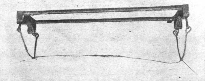
Bombs and Bomb Gear.
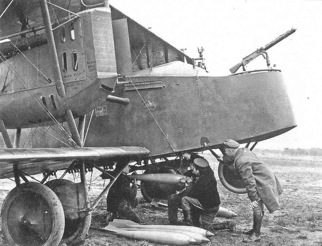
At each side of the covered-in passage-way in the nacelle are bomb racks, shown in Fig. 54, capable of holding five 25-pounder (12 kg.) bombs. Underneath the nacelle are carried two large tubular frames, fitted with cradles of steel cable and furnished with the usual form of trip gear. These racks, illustrated in Fig. 55, would, it is believed, be capable of supporting a 300 kg. bomb a-piece. The bombs carried, however, evidently vary with the radius of action over which the aeroplane has to operate. The large racks are not permanently attached to the nacelle, but can easily be removed as required.
Fig. 23 shows the inside of the front cockpit from which the release of the bombs is conducted. There are seven triggers for the small bomb racks and two levers for the large bomb trips, as shown in Fig. 56. The cables for this gear are carried under the floor, and are painted different colours for distinction.
Bomb-sight.
The bomb-sight carried on the machine presents no new features, and is of the ordinary German non-precision type.
Fabric and Dope.
Two entirely different kinds of fabric are employed in the Friedrichshafen machine. The wings are covered with a low-grade linen of the class which is employed on most of the enemy machines. It is white in colour. Compared with that of British fabrics, the tensile strength is fairly good.
This fabric is covered with a cellulose acetate dope, and is camouflaged in large irregular lozenges of dull colours, including blue-black, dark green, and earth colour.
The other fabric, which is applied to the fuselage, tail planes, rudder, elevator, fin and landing gear, is apparently a cheap material much inferior to British fabrics designed for a similar purpose. This fuselage fabric is dyed in a regular pattern of lozenges, the colours being hardly distinguishable from black. The dope is acetate of cellulose.
In both cases the dope seems to be carelessly applied.
Changes in Design.
When compared with the Fdh. GUI., No. 177/17 (of 13/9/17) brought down by the French, this Friedrichshafen presents a few differences in detail design, amongst which the following points may be noted :-
(1) Engine fairing. In No. 177 spinners were mounted on the propeller bosses, and an aluminium ring of large diameter mounted on the rear extremities of the engine bearers in order to carry the rearmost fairing panels.
(2) Exhaust pipe. In the No. 177 this was, as in the present case, trumpet shaped and turned back at the end, but instead of a series of slots being used, the open vent was "bottled" so that the orifice was slightly restricted, and an additional circle of small holes provided.
(3) Engine bearers. These were of ash in the No. 575, and the L-shaped extension was not used. The method of building up the bearers was, however, similar to that described.
(4) The weight empty was 2,665 kg. in the No. 177, as against 2,695 in the machine under review.
(5) The air-scoops under the engine fairing were smaller.
(6) The arrangement of the instruments, taps, &c, on the dashboard was quite different.
 |
J.Herris - Friedrichshafen Aircraft of WWI /Centennial Perspective/ (21)
|
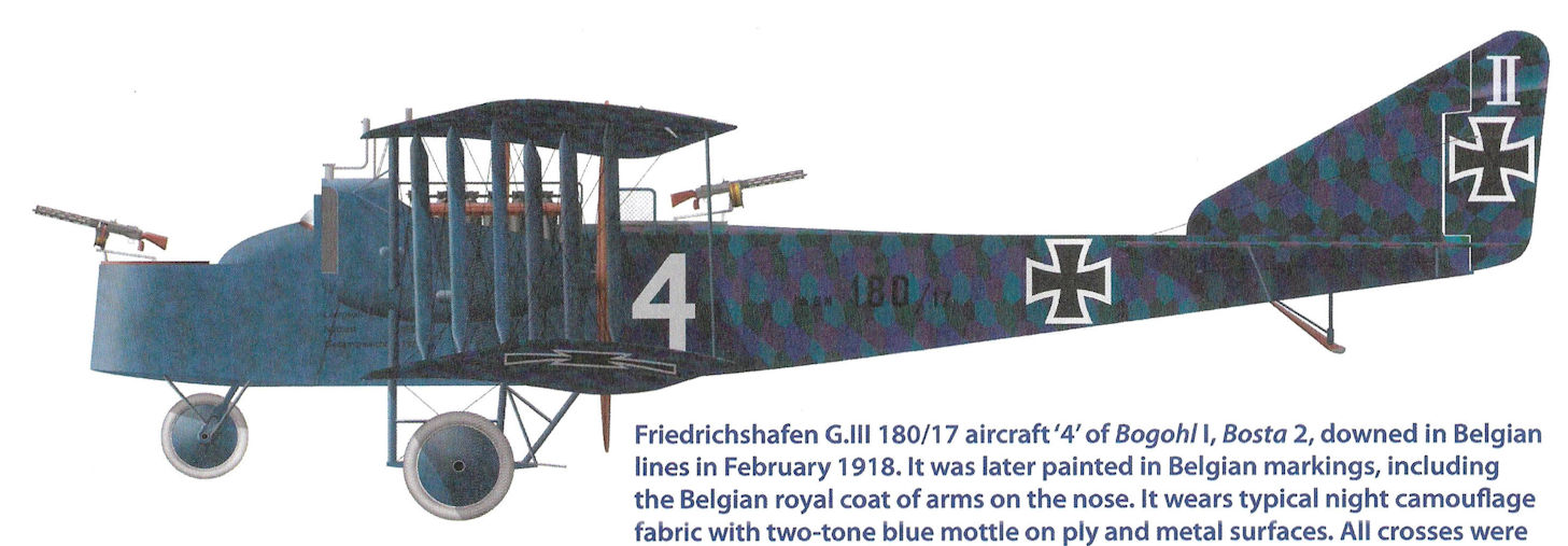
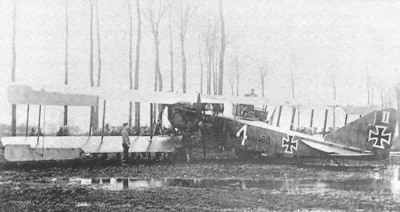
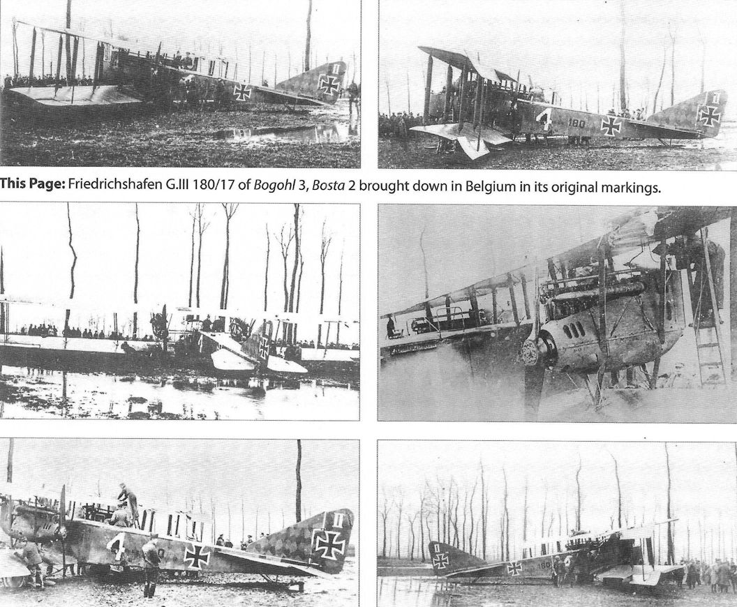
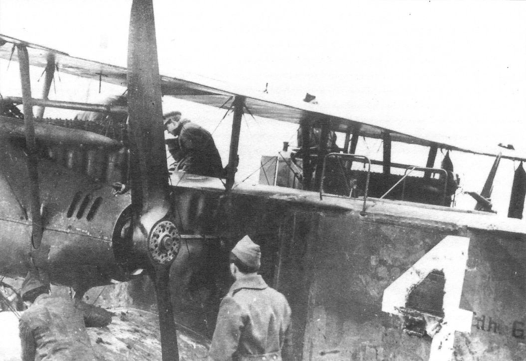
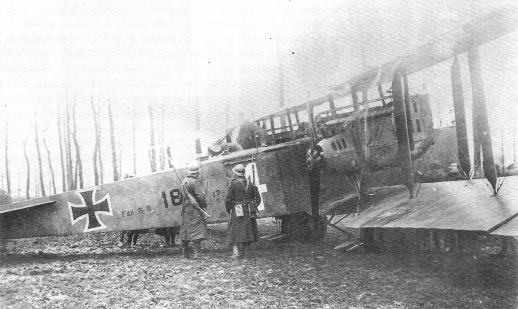
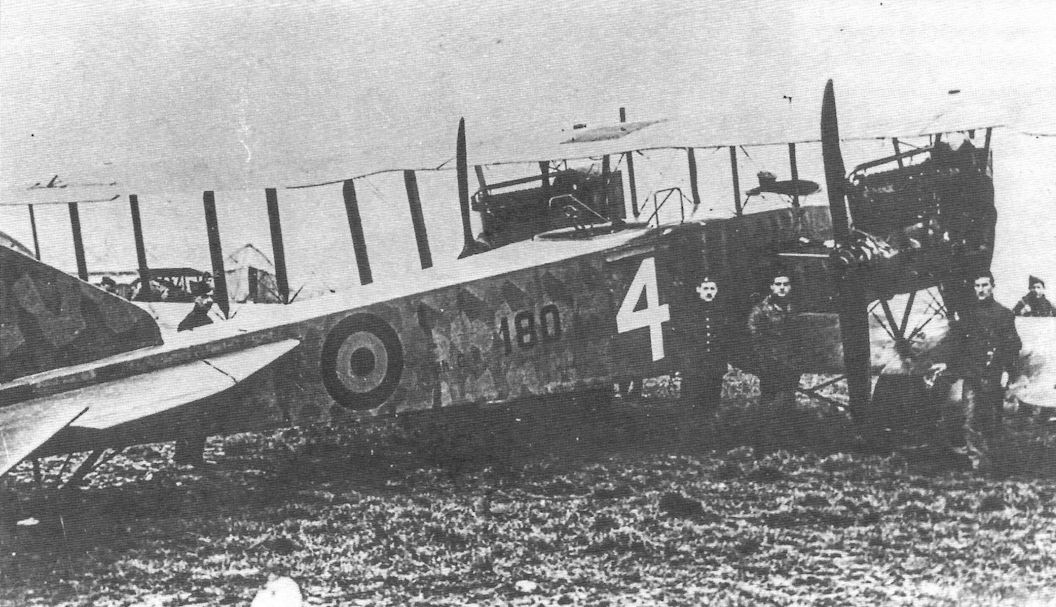
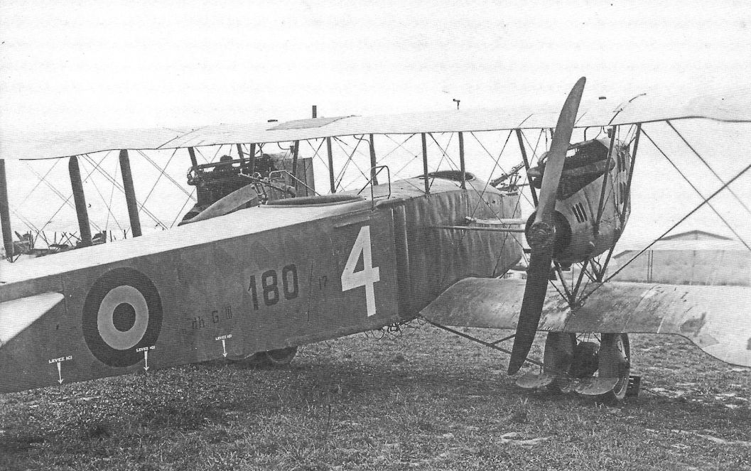
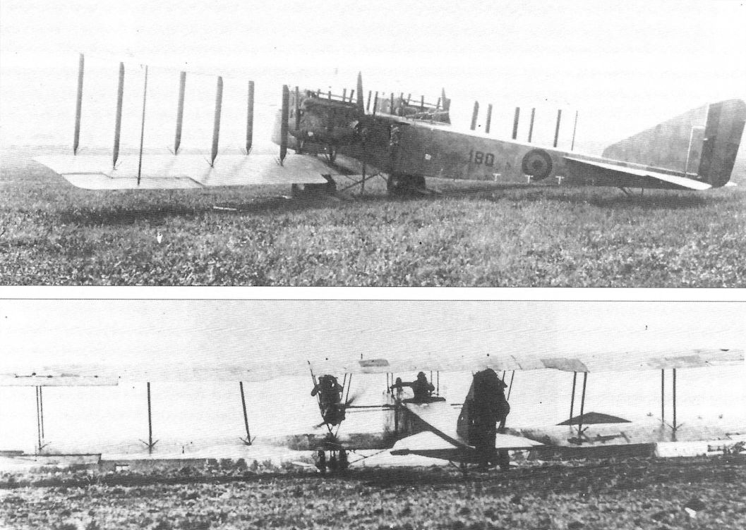
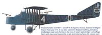
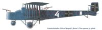
| Friedrichshafen G.III 180/17 aircraft '4' of Bogohl I, Bosta 2, downed in Belgian lines in February 1918. It was later painted in Belgian markings, including the Belgian royal coat of arms on the nose. It wears typical night camouflage fabric with two-tone blue mottle on ply and metal surfaces. All crosses were outlined.
|
 |
J.Herris - Friedrichshafen Aircraft of WWI /Centennial Perspective/ (21)
|
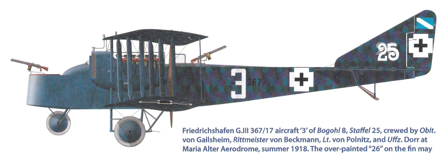
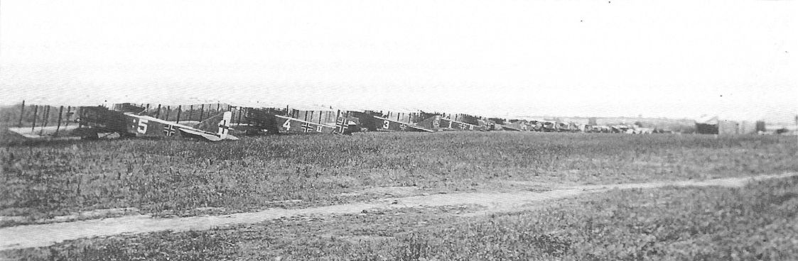
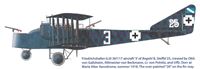
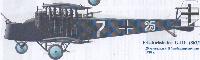
| Friedrichshafen G.III 367/17 aircraft '3' of Bogohl 8, Staffel 25, crewed by Oblt. von Gailsheim, Rittmeister von Beckmann, Lt. von Polnitz, and Uffz. Dorr at Maria Alter Aerodrome, summer 1918. The over-painted "26" on the fin may indicate the aircraft was transferred from Staffel 26.
|
 |
J.Herris - Friedrichshafen Aircraft of WWI /Centennial Perspective/ (21)
|
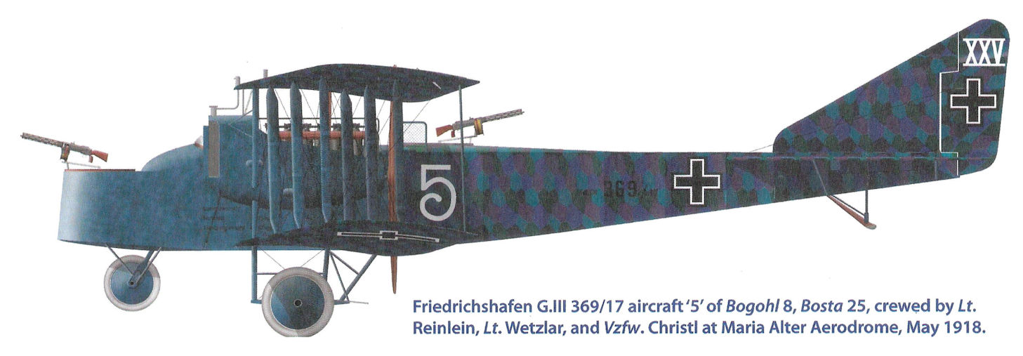
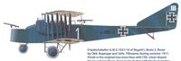
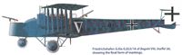
| Friedrichshafen G.III 369/17 aircraft ‘5’ of Bogohl 8, Bosta 25, crewed by Lt. Reinlein, Lt. Wetzlar, and Vzfw. Christi at Maria Alter Aerodrome, May 1918.
|
 |
J.Herris - Friedrichshafen Aircraft of WWI /Centennial Perspective/ (21)
|
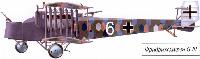
| Friedrichshafen G.III aircraft '6' of Bogohl V, Staffel 4, summer 1917.
|
 |
J.Herris - Friedrichshafen Aircraft of WWI /Centennial Perspective/ (21)
|
| Friedrichshafen G.III G.1031/16 of Bogohl I, Bosta 3, flown by Oblt. Kupinger and Vzfw. Tillmanns during summer 1917. Finish is the original two-tone blue with CDL (clear-doped linen) undersurfaces, here made darker with black squiggles.
|
 |
J.Herris - Friedrichshafen Aircraft of WWI /Centennial Perspective/ (21)
|
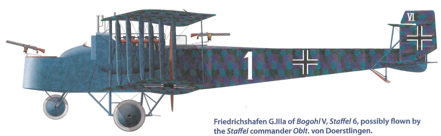
| Friedrichshafen G.IIIa of Bogohl V, Staffel 6, possibly flown by the Staffel commander Oblt, von Doerstlingen.
|
 |
J.Herris - Friedrichshafen Aircraft of WWI /Centennial Perspective/ (21)
|
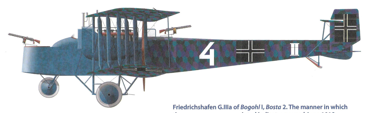
| Friedrichshafen G.IIIa of Bogohl I, Bosta 2. The manner in which the crosses were over-painted indicates around June 1918.
|
 |
В.Обухович, А.Никифоров - Самолеты Первой Мировой войны
|
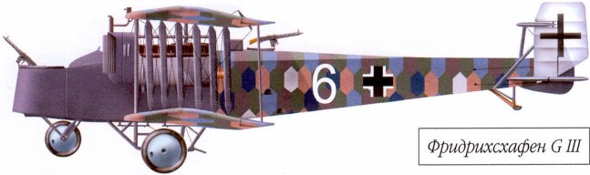
| Фридрихсхафен G III
|
 |
В.Кондратьев - Самолеты первой мировой войны
|
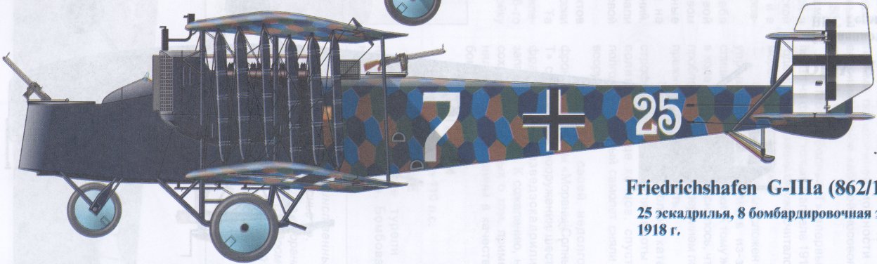
| Friedrichshafen G-IIIa (862/18), 25 эскадрилья, 8 бомбардировочная эскадра ВВС Германии, 1918г.
|
 |
J.Herris - Friedrichshafen Aircraft of WWI /Centennial Perspective/ (21)
|
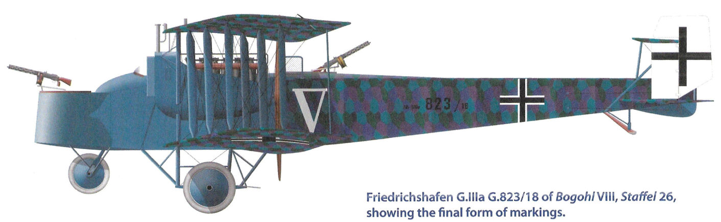
| Friedrichshafen G.IIIa G.823/18 of Bogohl VIII, Staffel 26, showing the final form of markings.
|
 |
J.Herris - Friedrichshafen Aircraft of WWI /Centennial Perspective/ (21)
|
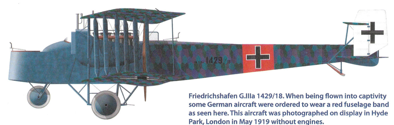
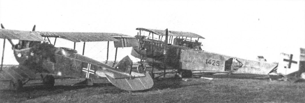
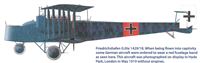
| Friedrichshafen G.IIIa 1429/18. When being flown into captivity some German aircraft were ordered to wear a red fuselage band as seen here. This aircraft was photographed on display in Hyde Park, London in May 1919 without engines.
|
 |
J.Herris - Friedrichshafen Aircraft of WWI /Centennial Perspective/ (21)
|
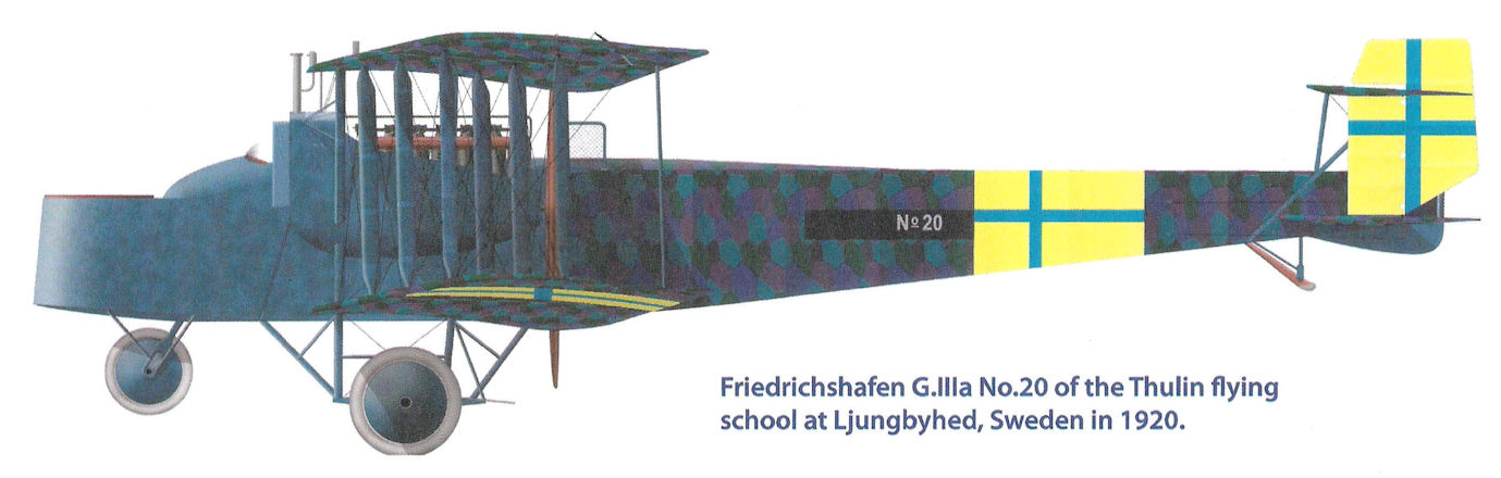
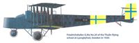
| Friedrichshafen G.IIIa No.20 of the Thulin flying school at Ljungbyhed, Sweden in 1920.
|
 |
J.Herris - Friedrichshafen Aircraft of WWI /Centennial Perspective/ (21)
|
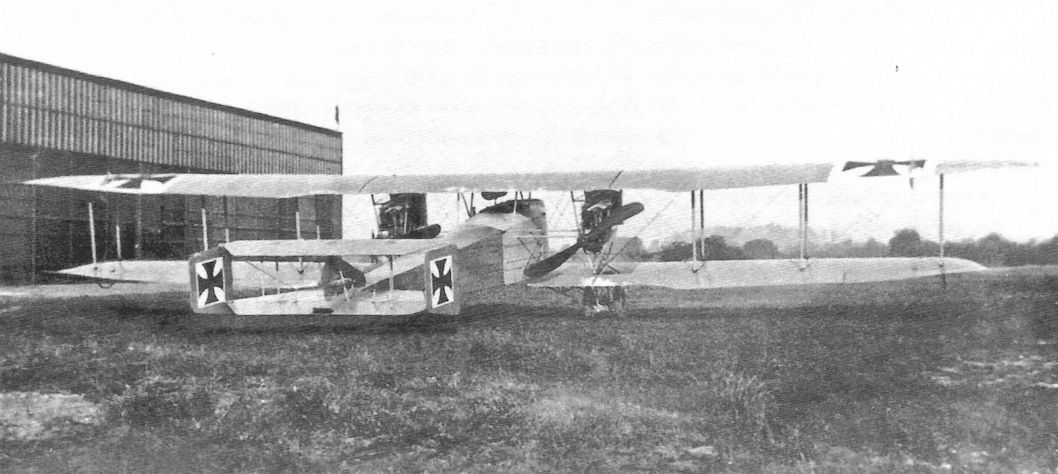
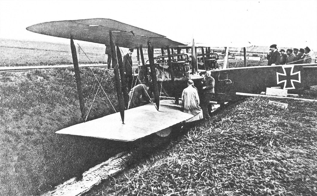
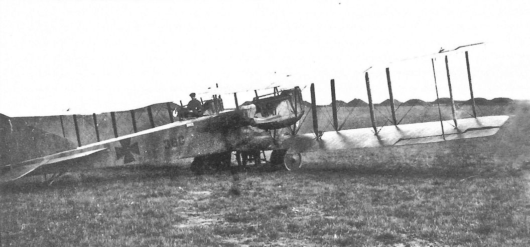
| The Friedrichshafen G.I set the basic configuration for all following Friedrichshafen bombers. Only one prototype was built and evaluated before Idflieg ordered an improved, more powerful derivative, the Friedrichshafen G.II. (Peter M. Bowers Collection, Museum of Flight)
|
 |
J.Herris - Friedrichshafen Aircraft of WWI /Centennial Perspective/ (21)
|
|
|
 |
O.Thetford, P.Gray - German Aircraft of the First World War /Putnam/
|
| Friedrichshafen G I
|
 |
J.Herris - Friedrichshafen Aircraft of WWI /Centennial Perspective/ (21)
|
| A rare image of what is believed to be the sole Friedrichshafen G I of 1915, sire to an illustrious, if largely unsung series of bombers, that largely preceded the Gothas, were easier to fly and were built in comparable numbers. Little has survived concerning the G I other than that it used two 150hp Benz Bz IIIs and pre-dates the debut of the rival Gotha G II by the best part of a year.
|
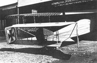 |
J.Herris - Friedrichshafen Aircraft of WWI /Centennial Perspective/ (21)
|
| The Friedrichshafen G.I under construction. When more powerful engines were added to later Friedrichshafen designs, larger, taller rudders were required. (Peter M. Bowers Collection, Museum of Flight)
|
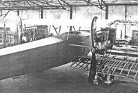 |
J.Herris - Friedrichshafen Aircraft of WWI /Centennial Perspective/ (21)
|
| The Friedrichshafen G.I during construction; the G.I was designed without a rear gunner's position, a feature added to all operational Friedrichshafen bombers. Other than that, the subsequent Friedrichshafen bombers designs generally followed the basic configuration and structure of the G.I. (Peter M. Bowers Collection, Museum of Flight)
|
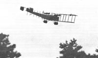 |
J.Herris - Friedrichshafen Aircraft of WWI /Centennial Perspective/ (21)
|
| The Friedrichshafen G.I during flight evaluation, which revealed the need for more power. (Peter M. Bowers Collection, Museum of Flight)
|
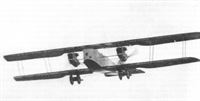 |
J.Herris - Friedrichshafen Aircraft of WWI /Centennial Perspective/ (21)
|
| A Friedrichshafen G.II in flight shows its two-bay wing bracing and typical Friedrichshafen configuration. The horizontal struts between the engine and fuselage below the upper longeron indicate either a prototype or a Daimler-built aircraft. (Peter M. Bowers Collection, Museum of Flight)
|
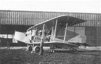 |
J.Herris - Friedrichshafen Aircraft of WWI /Centennial Perspective/ (21)
|
| Apparently the Friedrichshafen G.II prototype with early vertical tail surfaces. (Peter M. Bowers Collection, Museum of Flight)
|
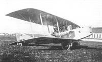 |
J.Herris - Friedrichshafen Aircraft of WWI /Centennial Perspective/ (21)
|
| Apparently the Friedrichshafen G.II prototype with early vertical tail surfaces. (Peter M. Bowers Collection, Museum of Flight)
|
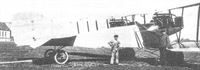 |
J.Herris - Friedrichshafen Aircraft of WWI /Centennial Perspective/ (21)
|
| Prototype G.II with initial tail design.
|
 |
J.Herris - Friedrichshafen Aircraft of WWI /Centennial Perspective/ (21)
|
| Prototype G.II with production tail design.
|
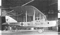 |
J.Herris - Friedrichshafen Aircraft of WWI /Centennial Perspective/ (21)
|
Friedrichshafen G.II 131/15, the G.II prototype, in the factory. Here it has been modified from its original configuration by a taller fin and balanced rudder. (Peter M. Bowers Collection, Museum of Flight)
Friedrichshafen G II, 131/15, seen here, was powered by two 215hp pusher-mounted Benz Bz IVs and carried a three man crew. The G II became operational in early 1916, but was only built in small numbers, being succeeded by the much larger Friedrichshafen G III, of which nearly 350 were built.
|
 |
J.Herris - Friedrichshafen Aircraft of WWI /Centennial Perspective/ (21)
|
| The prototype Friedrichshafen G.II, G.131/15, at the factory. This photo shows the aircraft before modifications to the fuselage structure because the horizontal struts between the engine and fuselage are attached below the upper fuselage longeron.This feature was shared by Daimler-built aircraft but production Friedrichshafen-built aircraft had the struts attached to the upper longerons. (Peter M. Bowers Collection, Museum of Flight)
|
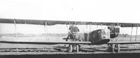 |
J.Herris - Friedrichshafen Aircraft of WWI /Centennial Perspective/ (21)
|
| Another view of Friedrichshafen G.II G.134/15 showing the dramatic nose art that was applied. The horizontal engine struts attached to the upper fuselage longeron characterized production Friedrichshafen-built aircraft after structural modifications were applied to the fuselage. Only prototype Friedrichshafen-built aircraft had these struts mounted lower as seen on G.131/15. (Peter M. Bowers Collection, Museum of Flight)
|
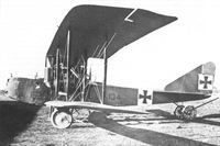 |
J.Herris - Friedrichshafen Aircraft of WWI /Centennial Perspective/ (21)
|
| Friedrichshafen G.II G.134/15 from the first G.II production batch.
|
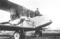 |
J.Herris - Friedrichshafen Aircraft of WWI /Centennial Perspective/ (21)
|
| A Friedrichshafen G.II(Daim), characterized by the horizontal struts between the engine and fuselage attaching below the upper longeron. This may be Daimler test pilot Irrek after the successful acceptance flight of the first G.II(Daim) 625.17 on March 3, 1917.
|
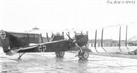 |
J.Herris - Friedrichshafen Aircraft of WWI /Centennial Perspective/ (21)
|
| Friedrichshafen G.II(Daim) 625/16 was the first Friedrichshafen bomber built by Daimler, which produced 298 Friedrichshafen bombers under license. Here it is undergoing its type test at Adlershof in April 1917. The G.II was the first Friedrichshafen twin-engine bomber design to see production and operational service and established the basic pattern followed by all subsequent Friedrichshafen bomber designs.
|
 |
O.Thetford, P.Gray - German Aircraft of the First World War /Putnam/
|
| Friedrichshafen G II
|
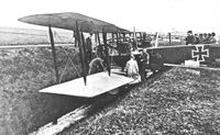 |
J.Herris - Friedrichshafen Aircraft of WWI /Centennial Perspective/ (21)
|
| A Friedrichshafen G.II(Daim) in the drainage ditch on the Daimler airfield at Sindelfingen. The ditch was the source of many complaints from Daimler test pilots. (Peter M. Bowers Collection, Museum of Flight)
|
 |
J.Herris - Friedrichshafen Aircraft of WWI /Centennial Perspective/ (21)
|
| Friedrichshafen G.III 1030/16 ordered in November 1916 was the first production G.III.
|
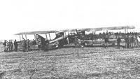 |
J.Herris - Friedrichshafen Aircraft of WWI /Centennial Perspective/ (21)
|
| Friedrichshafen G.III 1031/16 of Kampfstaffel 3.
|
 |
J.Herris - Friedrichshafen Aircraft of WWI /Centennial Perspective/ (21)
|
| This early model Friedrichshafen G.III still has the windows in the nose like the earlier G.II.
|
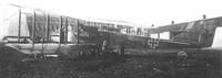 |
J.Herris - Friedrichshafen Aircraft of WWI /Centennial Perspective/ (21)
|
| Friedrichshafen G.III 167/17 in night bomber camouflage. (Peter M. Bowers Collection/Museum of Flight)
|
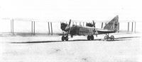 |
J.Herris - Friedrichshafen Aircraft of WWI /Centennial Perspective/ (21)
|
| Friedrichshafen G.III 179/17 was covered with the typical dark, night bomber printed camouflage fabric.
|
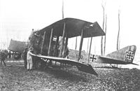 |
J.Herris - Friedrichshafen Aircraft of WWI /Centennial Perspective/ (21)
|
|
|
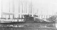 |
J.Herris - Friedrichshafen Aircraft of WWI /Centennial Perspective/ (21)
|
| Friedrichshafen G.III 180/17 of Bogohl I, Bosta 2 was brought down near Ghent, Belgium in February 1918.
|
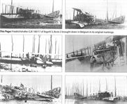 |
J.Herris - Friedrichshafen Aircraft of WWI /Centennial Perspective/ (21)
|
| Friedrichshafen G.III 180/17 of Bogohl 3, Bosta 2 brought down in Belgium in its original markings.
|
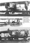 |
J.Herris - Friedrichshafen Aircraft of WWI /Centennial Perspective/ (21)
|
| Friedrichshafen G.III 180/17 of Bogohl 3, Bosta 2 brought down in Belgium in its original markings. It carried a crown insignia on a shield. The bracket for the landing lights is visible under the nose.
|
 |
J.Herris - Friedrichshafen Aircraft of WWI /Centennial Perspective/ (21)
|
| Friedrichshafen G.III 180/17 of Bogohl 3, Bosta 2 brought down in Belgium. The image shows details of the engine, propeller, and rear gunner's cockpit.
|
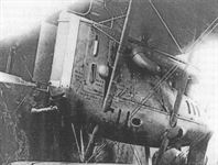 |
J.Herris - Friedrichshafen Aircraft of WWI /Centennial Perspective/ (21)
|
| Friedrichshafen G.III 180/17 of Bogohl 3, Bosta 2 brought down in Belgium. The image shows details of the engine cowling and radiator. The aircraft type and serial are clearly visible on the engine cowling.
|
 |
J.Herris - Friedrichshafen Aircraft of WWI /Centennial Perspective/ (21)
|
| Friedrichshafen G.III 180/17 of Bogohl 3 brought down in Belgium February 18, 1918, in its original markings.
|
 |
J.Herris - Friedrichshafen Aircraft of WWI /Centennial Perspective/ (21)
|
| Friedrichshafen G.III 180/17 of Bogohl I brought down in Belgium after conversion to Belgian markings.
|
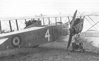 |
J.Herris - Friedrichshafen Aircraft of WWI /Centennial Perspective/ (21)
|
| Friedrichshafen G.III 180/17 of Bogohl 1, Bosta 2 after capture in February 1918 with Belgian insignia applied.
|
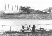 |
J.Herris - Friedrichshafen Aircraft of WWI /Centennial Perspective/ (21)
|
|
|
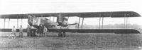 |
J.Herris - Friedrichshafen Aircraft of WWI /Centennial Perspective/ (21)
|
| This Friedrichshafen G.III has a test probe fitted on the nose and has rudder stripes indicating an aircraft captured by the Allies. It is likely G.III 180/17.
|
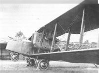 |
J.Herris - Friedrichshafen Aircraft of WWI /Centennial Perspective/ (21)
|
| Friedrichshafen G.III 180/17 under evaluation at the French test center at Villacoublay. Like the Gotha G.V which it resembled, the Friedrichshafen G.III used 260 hp Mercedes D.IVa engines mounted in nacelles above the wing. The nosewheel helped prevent nose-overs during landing, one factor that made it safer to fly than Gothas. Another factor in flight safety was the center of gravity was in the right place, not aft like the Gotha bombers.
|
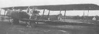 |
H.Cowin - Aviation Pioneers /Osprey/
|
| Although always overshadowed in the public eye by the Gotha name, the Friedrichshafen G III equipped three of the eight German bomber wings at the time of the Armistice. Larger and heavier than the contemporary Gotha G IV, the G III carried a far heavier bomb load and seemed far less susceptible to the landing gear failures that constantly beset the Gothas. With a 3-man crew, the G III was powered by two 260hp Mercedes D IVs and could carry up to 3,300 lb of bombs. Armed with two or three 7.92mm Parabellums, the G III had a top level speed of 87mph at 3,280 feet, along with a duration of 5 hours, implying a tactical radius of action, with full bomb load, of around 140 to 145 miles. Deployed initially in mid-1917, the G III and G IIIa went on to equip KG 1, KG 2 and KG 4 during 1917 and 1918.
|
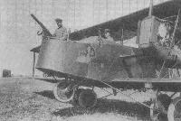 |
В.Кондратьев - Самолеты первой мировой войны
|
| "Фридрихсхафен" G-III на западном фронте, осень 1917г.
|
 |
J.Herris - Friedrichshafen Aircraft of WWI /Centennial Perspective/ (21)
|
| Frontal view of Friedrichshafen G.III bomber.
|
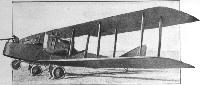 |
Jane's All The World Aircraft 1919 /Jane's/
|
| Three-quarter Front View of a Friedrichshafen G.III Bomber.
|
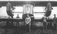 |
J.Herris - Friedrichshafen Aircraft of WWI /Centennial Perspective/ (21)
|
| This Friedrichshafen G.III of Staffel 3/Bogohl I, stationed at Tupigny, France, 1918, displays an elaborate coat of arms on the nacelle. Landing lights are also prominently placed under the nose to provide sufficient light for landing in dark or foggy conditions. Vzfw. Sturm was the aircraft commander. (Peter M. Bowers Collection/Museum of Flight)
|
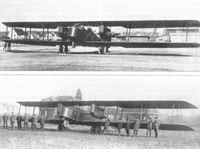 |
J.Herris - Friedrichshafen Aircraft of WWI /Centennial Perspective/ (21)
|
| Frontal views of Friedrichshafen G.III bombers.
|
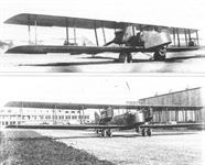 |
J.Herris - Friedrichshafen Aircraft of WWI /Centennial Perspective/ (21)
|
| Frontal views of Friedrichshafen G.III bombers.
|
 |
J.Herris - Friedrichshafen Aircraft of WWI /Centennial Perspective/ (21)
|
| This Friedrichshafen G.III has spinners on its propellers and appears to be at the Daimler factory.
|
 |
J.Herris - Friedrichshafen Aircraft of WWI /Centennial Perspective/ (21)
|
| Friedrichshafen G.III engine details.
|
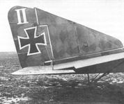 |
J.Herris - Friedrichshafen Aircraft of WWI /Centennial Perspective/ (21)
|
| Tail details of a Friedrichshafen G.III. The pattern of the night-bomber camouflage fabric shows up well; often it is too dark to show up clearly.
|
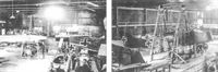 |
J.Herris - Friedrichshafen Aircraft of WWI /Centennial Perspective/ (21)
|
| A Friedrichshafen G.III bomber in a hangar in the Netherlands.
|
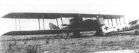 |
J.Herris - Friedrichshafen Aircraft of WWI /Centennial Perspective/ (21)
|
| An early-production Friedrichshafen G.III - note the windows in the nose - shares the field with the Albatros D.V D1016/17 of Ltn. von der Marwitz of Jasta 30 in June 1917.
|
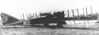 |
J.Herris - Friedrichshafen Aircraft of WWI /Centennial Perspective/ (21)
|
| This view shows the early-production Friedrichshafen G.III is from Kampfstaffel 5. The tail of the Albatros D.V of Ltn. von der Marwitz is barely visible behind the bomber.
|
 |
J.Herris - Friedrichshafen Aircraft of WWI /Centennial Perspective/ (21)
|
| Another view of the early-production Friedrichshafen G.III from Kampfstaffel 5. Fighter pilots from Jasta 30 relax between sorties during the day while a Friedrichshafen G.III night bomber appears in the background. Fighter crews flew primarily from dawn till dusk while the Friedrichshafen bomber crews often flew under the cover of darkness. Ltn. von der Marwitz Albatros has been moved. In the foreground Jasta 30 pilots prepare for their next combat.
|
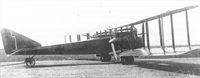 |
J.Herris - Friedrichshafen Aircraft of WWI /Centennial Perspective/ (21)
|
| Friedrichshafen G.III(Daim) 241/17 was the second G.III built by Daimler under license. In an attempt to maximize its performance by minimizing drag the pusher propeller even has a spinner fitted.
|
 |
J.Herris - Friedrichshafen Aircraft of WWI /Centennial Perspective/ (21)
|
| Friedrichshafen G.III(Daim) 25X/17 sports its iron cross high on its rudder, characteristice of Daimler-built G.IIIs.
|
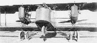 |
A.Imrie - German Bombers /Arms & Armour/
|
| The landing lights built into the top wing leading edges of this Friedrichshafen G III (271/17) used low-resistance bulbs, fed by a battery of 12-volt accumulators, and they could illuminate the ground for a distance of 50m ahead from a height of 4m. The aerodrome lighting did not always provide the necessary reference to allow the pilot to place his aeroplane in the correct landing attitude at the right height, and the nosewheel undercarriage was used to lessen the risk of damage by flying into the ground.
|
 |
O.Thetford, P.Gray - German Aircraft of the First World War /Putnam/
|
| Friedrichshafen G III (serial 271/17)
|
 |
J.Herris - Friedrichshafen Aircraft of WWI /Centennial Perspective/ (21)
|
| Friedrichshafen G.III(Daim) 356/17 was one of a batch of 100 ordered in June 1917 and wears a personal marking on the side of its nose. It has no rudder cross and the fuselage cross does not have a white outline.
|
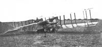 |
J.Herris - Friedrichshafen Aircraft of WWI /Centennial Perspective/ (21)
|
| The Friedrichshafen G.III, which followed the basic configuration of all Friedrichshafen bombers, was the main production type. Its configuration was very similar to the Gotha series but the Friedrichshafen had much better handling qualities that made it a safer airplane to fly, especially during landing. This bomber is G.III 360/17.
|
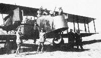 |
A.Imrie - German Bombers /Arms & Armour/
|
| Staffelfuehrer's Friedrichshafen G III 367/18 of Bosta 25, Bogohl VIII. Rittmeister Freiherr von Beckmann is in the observer's front cockpit: the Staffelfuehrer, Oberleutnant Freiherr von Crailsheim (with signal flares in his top pocket), and Leutnant Freiherr von Polnitz in the pilot's cockpit. The non-optical Goerz bombsight on the nose was more suitable for use at night than the 'bombing telescope'. It consisted of a fixed foresight at the apex of the triangular frame and an illuminated backsight at the top which was set with height and groundspeed; when the target entered the crosswires on the backsight, and lined up with the foresight, the bombs were released.
|
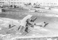 |
J.Herris - Friedrichshafen Aircraft of WWI /Centennial Perspective/ (21)
|
| Friedrichshafen G.III(Daim) 392/17 prepares for a flight from the Daimler factory at Sindelfingern. The rudder cross is located at the top of the rudder, a hallmark of Daimler-built G.III bombers. Interestingly, there are no crosses on the upper wing surfaces.
|
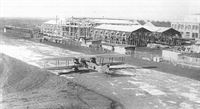 |
J.Herris - Friedrichshafen Aircraft of WWI /Centennial Perspective/ (21)
|
|
|
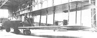 |
P.Grosz, G.Haddow, P.Shiemer - Austro-Hungarian Army Aircraft of World War One /Flying Machines/
|
| Friedrichshafen G.IIIa(Daim) 789/17 awaiting propeller installation in the Oeffag flight hangar at Wiener-Neustadt.
|
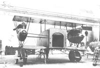 |
P.Grosz, G.Haddow, P.Shiemer - Austro-Hungarian Army Aircraft of World War One /Flying Machines/
|
| All but the largest German aircraft were designed to be disassembled for rail shipment. The Friedrichshafen G.IIIa (Daim) 789/17 center fuselage module is in process of assembly after arrival at the Oeffag factory.
|
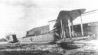 |
J.Herris - Friedrichshafen Aircraft of WWI /Centennial Perspective/ (21)
|
| Friedrichshafen G.IIIa G.789/18 (789/17 ???) at Oeffag in August 1918; this aircraft had 250 hp Benz Bz.IV(Mar) engines built in Austria instead of the usual 260 hp Mercedes. The G.IIIa featured a number of improvements over the G.III. The most obvious was the 'box' tail to improve directional control with one engine inoperative. Other improvements included a 'Gotha tunnel' to improve the rear gunner's downward field of fire, greater fuel capacity for longer range, greater bombload, and Flettner servo-tabs on the ailerons to reduce the control forces and thus the pilot's workload.
|
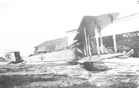 |
P.Grosz, G.Haddow, P.Shiemer - Austro-Hungarian Army Aircraft of World War One /Flying Machines/
|
| The G.IIIa(Daim) 789/17 fully assembled and ready for flight trials on the Oeffag airfield. Neither of the two Friedrichshafen bombers delivered to Oeffag received an LFT designation number.
|
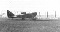 |
J.Herris - Friedrichshafen Aircraft of WWI /Centennial Perspective/ (21)
|
| A Friedrichshafen G.III on its take-off run.
|
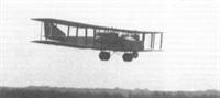 |
J.Herris - Friedrichshafen Aircraft of WWI /Centennial Perspective/ (21)
|
| A Friedrichshafen G.III 828/17 comes in for a landing.
|
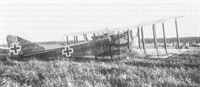 |
J.Herris - Friedrichshafen Aircraft of WWI /Centennial Perspective/ (21)
|
| Friedrichshafen G.III 828/17 landed in the Netherlands and was interned.
|
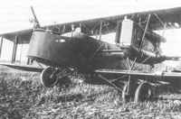 |
J.Herris - Friedrichshafen Aircraft of WWI /Centennial Perspective/ (21)
|
| Another view of Friedrichshafen G.III 828/17 that landed in the Netherlands and was interned.
|
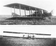 |
J.Herris - Friedrichshafen Aircraft of WWI /Centennial Perspective/ (21)
|
| Friedrichshafen G.III 828/17 landed in the Netherlands and was interned.
|
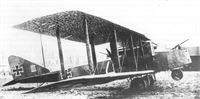 |
J.Herris - Friedrichshafen Aircraft of WWI /Centennial Perspective/ (21)
|
| This Friedrichshafen G.III of Kampfstaffel 3 has unusual unit-applied camouflage under its wings.
|
 |
J.Herris - Friedrichshafen Aircraft of WWI /Centennial Perspective/ (21)
|
| Friedrichshafen G.III and G.IIIa bombers of Bogohl I in 1918.
|
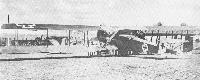 |
A.Imrie - German Bombers /Arms & Armour/
|
| Two Friedrichshafen G III machines on a training aerodrome in Germany, probably the Geschwaderschule at Paderborn, in April 1918. The nearest aircraft (G 347/17) has the box tail unit that became standard on the G IIIa; it also has the four-bay wing cellule that was the hallmark of the G IV, and is possibly one of the prototype aircaft used to introduce these features, brought to Paderborn for demonstration purposes. Pilots were converted to twin-engined types at this school. After flying solo, flights were made with increasing amounts of ballast up to maximum weight, by both day and night. Cross-country flights were undertaken during which specified periods had to be spent above a height of 2,000m. The final requirements included day and night exercises on the bombing range. Duration of courses varied but could take up to eight weeks.
|
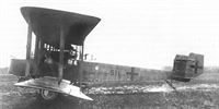 |
J.Herris - Friedrichshafen Aircraft of WWI /Centennial Perspective/ (21)
|
| This image lend scale and substance to Friedrichshafen's G IIIa. Operationally deployed for the first time during the spring of 1918, the G IIIa used the same engines as the G III, differing only in the adoption of a biplane tail unit. Production of the 345 G III and G IIIa aircraft was shared between the parent company, Hanseatische and Daimler.
|
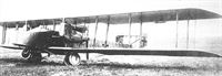 |
J.Herris - Friedrichshafen Aircraft of WWI /Centennial Perspective/ (21)
|
| Friedrichshafen 511/18 was a transition aircraft; it was ordered as a G.III but was given the box tail and Flettnertabs of a G.IIIa during production at the factory.
|
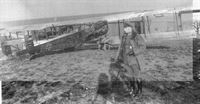 |
J.Herris - Friedrichshafen Aircraft of WWI /Centennial Perspective/ (21)
|
| Friedrichshafen G IIIa (Daim.) 779/18. This view of a sub-contract machine built by Daimler shows the Flettner balances mounted ahead of the aileron hinges on outriggers (Flettner tabs, Hilfsruder) and details of the box tail (Kastensteuer). Not only were twin-engined aircraft of the time unable to maintain height on one engine, but full power on the good engine caused the loss of directional control. During 1918 much experimental work resulted in the 'box tail unit' being adopted by AEG, Friedrichshafen and Gotha. The main asset was the placing of the rudder in the propeller slipstream where it benefitted from increased airflow, allowing straight ahead flight at full power on one engine, the rate of descent being considerably reduced. The biplane configuration of the tail unit was merely the best way to produce a braced structure strong enough to support the vertical tail surfaces.
|
 |
J.Herris - Friedrichshafen Aircraft of WWI /Centennial Perspective/ (21)
|
| Friedrichshafen G.IIIa 779/18.
|
 |
J.Herris - Friedrichshafen Aircraft of WWI /Centennial Perspective/ (21)
|
| Engine details of Friedrichshafen G.III(Daim) 779/18, the last aircraft of a batch of 30. Some of these aircraft, like 779/18, were transition aircraft with the G.IIIa box tail (Kastensteuer) and Flettner tabs (Hilfsruder).
|
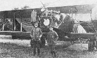 |
A.Imrie - German Bombers /Arms & Armour/
|
| Oberleutnant Freiherr Marschall von Bieberstein, Staffelfuehrer of Bosta II in Bogohl I, with his pilot, Leutnant Nieber, in front of their Friedrichshafen G IIIa 836/18. One of the most resolute bomber commanders, von Bieberstein, for whom the heaviest anti-aircraft fire held no terrors, rejoiced in the nickname of 'Emir - enemy of the infidels'. The decorative laurel wreath on the nose of his aircraft is in celebration of his return from his 250th operational flight.
|
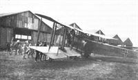 |
J.Herris - Friedrichshafen Aircraft of WWI /Centennial Perspective/ (21)
|
| Friedrichshafen G.IIIa 1052/18.
|
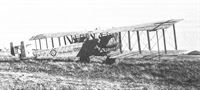 |
J.Herris - Friedrichshafen Aircraft of WWI /Centennial Perspective/ (21)
|
The Friedrichshafen G.IIIa(Daim) series 07 bomber ordered from Daimler would have been similar to this G.IIIa(Daim) 1056/18, shown in French hands after the war. The top ailerons are fitted with Flettner servo tabs originally developed for guided missiles.
Friedrichshafen G.IIIa(Daim) 1056/18 was turned over to the French according to the terms of the Armistice. Ordered in October 1918 and in pristine condition, it was probably delivered straight from the factory.
|
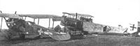 |
J.Herris - Friedrichshafen Aircraft of WWI /Centennial Perspective/ (21)
|
| Friedrichshafen 1425/18 in derelict condition postwar. It was ordered as a G.III but completed with the G.IIIa tail. The fuselage insignia have been cut out for souvenirs. An LVG C.VI missing its rudder rests at left.
|
 |
J.Herris - Friedrichshafen Aircraft of WWI /Centennial Perspective/ (21)
|
| Friedrichshafen G.IIIa 1429/18 without engines on display in Hyde Park, London on 14 May 1919.
|
 |
Журнал - Flight за 1919 г.
|
| "NOT A CASE OF BIRDS OF A FEATHER," etc. - The "bird" in the background is a captured German bomber now exhibited sans engine in St. James's Park. The flyer in the foreground is of a much more peaceful character, and hails, we believe, from China.
|
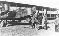 |
J.Herris - Friedrichshafen Aircraft of WWI /Centennial Perspective/ (21)
|
| Friedrichshafen G.III with aircrew and ground-crew members during bomb loading demonstrating a 300 kg P.u.W. bomb.
|
 |
J.Herris - Friedrichshafen Aircraft of WWI /Centennial Perspective/ (21)
|
| Friedrichshafen G.III being loaded with 50 kg bombs. The radiator details and forward gunner's position are nicely shown. A pintle mount for a second flexible forward-firing machine gun is mounted between the cockpits.
|
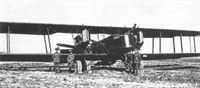 |
J.Herris - Friedrichshafen Aircraft of WWI /Centennial Perspective/ (21)
|
| The crew of a Friedrichshafen G.IIIa carrying a 1,000 kg PuW bomb poses with their aircraft.
|
 |
A.Imrie - German Bombers /Arms & Armour/
|
| Friedrichshafen G IIIa of Bosta 26. Bogohl VIII, with a 1,000kg bomb in its rack. This machine, probably the best G type to reach the Front in quantity, was actually capable of carrying a 1,500kg bombload with fuel for 6 hours. The already excellent undercarriage was further strengthened for heavy work by doubling the number of wheels originally fitted. Two hefty streamlined-section steel tubes filled with wood extended from the wing spars to a steel girder that supported the axles; shock-absorption was by coiled steel springs, this assembly being covered by a fabric bag to prevent the ingress of mud, etc. The nose wheel shock struts also used steel springs in compression. All undercarriage assemblies had drift bracing of streamlined steel tube; that on the main wheels precluded the use of bomb racks on the wing undersurfaces of the centresection.
|
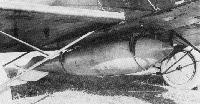 |
A.Imrie - German Bombers /Arms & Armour/
|
| Close-up of the 1,000kg P.u.W. bomb on its simple rack showing the nose safety pin in place. This weapon was first dropped experimentally in December 1917, had two fuses and was thin-walled to obtain the maximum blast effect from its 680kg of high-explosive. The angled tail fins imparted a rotary motion to the bomb during its fall which stabilized its trajectory. The centrifugal force generated was used to arm the bomb by causing three brass segments to move clear of the firing pistol, and needed a fall of 1,600m to operate. First live drops were made in January 1918 and 710 bombs of this type had been dropped on enemy targets by the end of the war.
|
 |
J.Herris - Friedrichshafen Aircraft of WWI /Centennial Perspective/ (21)
|
| The Friedrichshafen G.III was capable of carrying a 1,000 kg PuW (Prufanstalt und Werff) bomb as shown here. This bomb was first used in combat in January 1918.
|
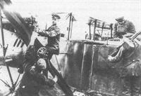 |
J.Herris - Friedrichshafen Aircraft of WWI /Centennial Perspective/ (21)
|
| Close up of the ground crew preparing a Friedrichshafen G.III for a mission.
|
 |
J.Herris - Friedrichshafen Aircraft of WWI /Centennial Perspective/ (21)
|
| Friedrichshafen G.IIIa 862/18 of Bogohl 8 in October 1918 during a flight for parachute testing.
|
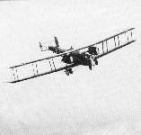 |
A.Imrie - German Bombers /Arms & Armour/
|
| On the crew state board (at caption No 72) Oberleutnant Karl lletzel had just reported to Bogohl VIII. Possibly because of his rank and the fact that Bosta 25 was below the established pilot strength, he was assigned to Bosta 25, taking over Leutnant Reinlein's crew: Leutnant Wetzlar, observer, and Vizefeldwebel Christl, machinegunner. He is seen here flying Friedrichshafen G IIIa 826/18 with these crew members on a practice flight which involved dropping parachute stores from the bottom hatch of the gunner's cockpit. This photograph, which is one of a sequence, was taken by Leutnant Woyl in the vicinity of Bolchen in Lothringen in October 1918.
|
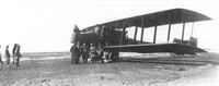 |
J.Herris - Friedrichshafen Aircraft of WWI /Centennial Perspective/ (21)
|
| This Friedrichshafen G.IIIa has attracted a great deal of attention, probably postwar.
|
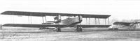 |
J.Herris - Friedrichshafen Aircraft of WWI /Centennial Perspective/ (21)
|
| The circumstances of this photo are unknown, but the robust Friedrichshafen G.IIIa dwarfs the fragile Bieriot.
|
 |
J.Herris - Gotha Aircraft of WWI /Centennial Perspective/ (6)
|
| Postwar lineup of a Gotha GL.VII (at left), an AEG (center), and a Friedrichshafen (at right) at Bickendorf. The GL.VII has a fuselage band over the cross insignia, its location indicating it was built by Aviatik.
|
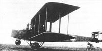 |
J.Herris - Friedrichshafen Aircraft of WWI /Centennial Perspective/ (21)
|
| A Friedrichshafen G.IIIa in British markings postwar.
|
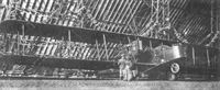 |
J.Herris - Friedrichshafen Aircraft of WWI /Centennial Perspective/ (21)
|
| Friedrichshafen G.IIIa photographed in British hands postwar.
|
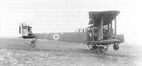 |
J.Herris - Friedrichshafen Aircraft of WWI /Centennial Perspective/ (21)
|
| This Friedrichshafen G.IIIa was turned over to the British postwar.
|
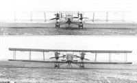 |
J.Herris - Friedrichshafen Aircraft of WWI /Centennial Perspective/ (21)
|
| Friedrichshafen G.IIIa photographed postwar. The box tail and Flettnertabs gave the pilot better control, especially in asymmetric thrust conditions after an engine failed.
|
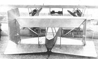 |
J.Herris - Friedrichshafen Aircraft of WWI /Centennial Perspective/ (21)
|
| Friedrichshafen G.IIIa tail details.
|
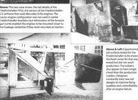 |
J.Herris - Friedrichshafen Aircraft of WWI /Centennial Perspective/ (21)
|
| Experimental tail surfaces tested for the Friedrichshafen G.IIIa shows the fixed center fin that was tested but did not reach production. The rudders also appear to have longer chord than the production rudders. Designers constantly tried new tail designs to improve flying qualities and controllability after an engine failure.
|
 |
J.Herris - Gotha Aircraft of WWI /Centennial Perspective/ (6)
|
| Gotha G.IX(LVG) serving in Belgium postwar illustrates the type's clean lines. It appears to be on public display. A Friedrichshafen bomber is in the background.
|
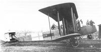 |
J.Herris - Friedrichshafen Aircraft of WWI /Centennial Perspective/ (21)
|
| Photographed in 1920, Friedrichshafen G.IIIa "20" was in Swedish markings at Sweden's Thulin flying school at Ljungbyhed. It had been delivered from Hamburg on 15 January 1920 and here has gained the attention of a group of four men and two women.
|
 |
J.Herris - Friedrichshafen Aircraft of WWI /Centennial Perspective/ (21)
|
| This appears to be the group of four men and two women photographed in Friedrichshafen G.IIIa "20" at Sweden's Thulin flying school at Ljungbyhed with the aircraft in the background.
|
 |
J.Herris - Friedrichshafen Aircraft of WWI /Centennial Perspective/ (21)
|
| Friedrichshafen G.IIIa(Daim) 1037/18 was modified to a passenger transport after the war and registered D 121, is shown here serving with the Deutsche Luftreederei. The Treaty of Versailles put an end to this service.
|
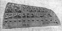 |
Журнал - Flight за 1918 г.
|
| Fig. 1. - Centre section of lower main plane with three-ply surfacing removed.
|
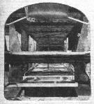 |
Журнал - Flight за 1918 г.
|
| Fig. 20. - View looking down inside of fuselage from the main nacelle, showing trap-door and after-gunner's folding seat.
|
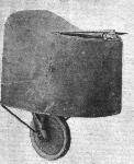 |
Журнал - Flight за 1918 г.
|
| Fig. 22. - Front portion of the nacelle.
|
 |
Журнал - Flight за 1918 г.
|
| Fig. 23. - Inside of the front cockpit.
|
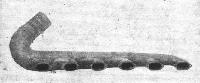 |
Журнал - Flight за 1918 г.
|
| Fig. 30. - The exhaust pipe of the 260 h.p. Mercedes engine.
|
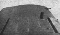 |
Журнал - Flight за 1918 г.
|
| Fig. 37. - Gravity petrol tank let into the centre section of the upper plane. Its fabric cover is held down by press buttons. Note the detachable panel in the trailing edge of the plane.
|
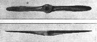 |
Журнал - Flight за 1918 г.
|
| Figs. 40 and 41. - Front and side views of the propeller. Note the two additional bolt holes.
|
 |
Журнал - Flight за 1918 г.
|
Fig. 46. - Main landing chassis with fabric fairing removed.
Fig. 47. - Landing wheel under the front portion of the nacelle.
|
 |
Журнал - Flight за 1918 г.
|
Fig. 48. - Tail skid.
Fig. 49. - Machine gun mounting in the front portion of the nacelle.
|
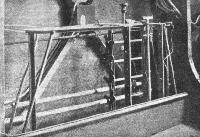 |
Журнал - Flight за 1918 г.
|
| Fig. 54. - View of bomb-rack in nacelle. Behind it can be seen the spring of trimming gear.
|
 |
Журнал - Flight за 1918 г.
|
| Fig. 55. - Large bomb-carrier.
|
 |
Журнал - Flight за 1918 г.
|
| Fig. 56. - Bomb-release gear inside front cockpit.
|
 |
А.Александров, Г.Петров - Крылатые пленники России
|
| (КПР 84)
|
 |
А.Александров, Г.Петров - Крылатые пленники России
|
(КПР 85)
Two civil German Friedrichshafen G IIIa bombers equipped for passenger transport were confiscated by the Soviets and entered service with the RKKVF in 1920.
|
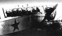 |
А.Александров, Г.Петров - Крылатые пленники России
|
| (КПР)
|
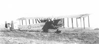 |
P.Grosz, G.Haddow, P.Shiemer - Austro-Hungarian Army Aircraft of World War One /Flying Machines/
|
| The Friedrichshafen G.IIIa(Daim) series 07 bomber ordered from Daimler would have been similar to this G.IIIa(Daim) 1056/18, shown in French hands after the war. The top ailerons are fitted with Flettner servo tabs originally developed for guided missiles.
|
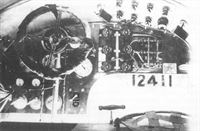 |
J.Herris - Friedrichshafen Aircraft of WWI /Centennial Perspective/ (21)
|
| The cockpit of a Friedrichshafen G.III. There was only one control wheel; there was a pilot but no copilot. The 12 controls on the center and upper right enable the pilot to manage the flow from the fuel tanks.
|
 |
J.Herris - Friedrichshafen Aircraft of WWI /Centennial Perspective/ (21)
|
| The passage allowing movement between the rear cockpit and the pilot's cockpit was introduced on the Friedrichshafen G.IIIb. The forward fuselage of this aircraft has not yet been completed.
|
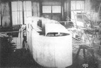 |
J.Herris - Friedrichshafen Aircraft of WWI /Centennial Perspective/ (21)
|
| A Friedrichshafen G.IIIb under construction?
|
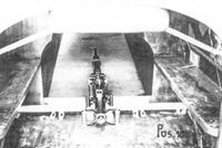 |
J.Herris - Friedrichshafen Aircraft of WWI /Centennial Perspective/ (21)
|
| Becker 2cm cannon tested in Friedrichshafen G.IIIa.
|
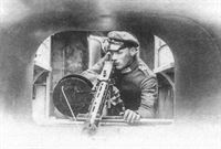 |
J.Herris - Friedrichshafen Aircraft of WWI /Centennial Perspective/ (21)
|
| "Gotha"gun tunnel added to Friedrichshafen G.IIIa.
|
 |
J.Herris - Friedrichshafen Aircraft of WWI /Centennial Perspective/ (21)
|
| This crashed Friedrichshafen G.III shows the hatch in the bottom of the fuselage to enable the rear gunner to fire downward to the rear to defend against fighters.
|
 |
J.Herris - Friedrichshafen Aircraft of WWI /Centennial Perspective/ (21)
|
| A crashed Friedrichshafen G.III spills its bombload.
|
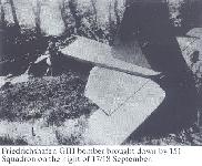 |
Сайт - Pilots-and-planes /WWW/
|
|
|
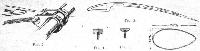 |
Журнал - Flight за 1918 г.
|
| Fig. 2. Fig. 3. Fig. 4. Fig. 5. Fig. 6.
|
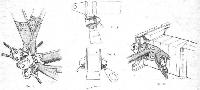 |
Журнал - Flight за 1918 г.
|
| Fig. 7. Fig. 8. Fig. 9. Fig. 10.
|
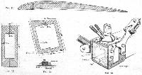 |
Журнал - Flight за 1918 г.
|
| Fig. 11. Fig. 12. Fig. 13. Fig. 14. Fig. 15.
|
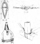 |
Журнал - Flight за 1918 г.
|
| Fig. 16. Fig. 17. Fig. 18. Fig. 19.
|
 |
Журнал - Flight за 1918 г.
|
| Fig. 21.
|
 |
Журнал - Flight за 1918 г.
|
| Fig. 24. Fig. 25.
|
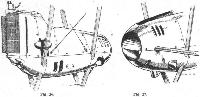 |
Журнал - Flight за 1918 г.
|
| Fig. 26. Fig. 27.
|
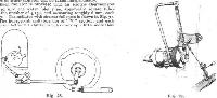 |
Журнал - Flight за 1918 г.
|
| Fig. 28. Fig. 29.
|
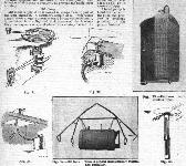 |
Журнал - Flight за 1918 г.
|
Fig. 31. Fig. 32.
Fig. 33. - Radiator, with shutter open.
Fig. 34.
Fig. 35. - Oil tank. This is placed Immediately behind the radiator.
Fig. 36.
|
 |
Журнал - Flight за 1918 г.
|
| Fig. 38. Fig. 39.
|
 |
Журнал - Flight за 1918 г.
|
| Fig. 42.
|
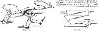 |
Журнал - Flight за 1918 г.
|
| Fig. 43. Fig. 44.
|
 |
Журнал - Flight за 1918 г.
|
| Fig. 45.
|
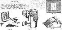 |
Журнал - Flight за 1918 г.
|
| Fig. 50. Fig. 51. Fig. 52. Fig. 53.
|
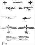 |
J.Herris - Friedrichshafen Aircraft of WWI /Centennial Perspective/ (21)
|
| Friedrichshafen G.III recognition chart provided to German units.
|
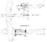 |
Сайт - Pilots-and-planes /WWW/
|
|
|
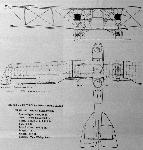 |
Jane's All The World Aircraft 1919 /Jane's/
|
| The 450-h.p. Friedrichshafen G.II Three-seater.
|
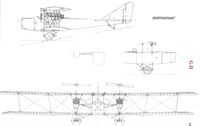 |
J.Herris - Friedrichshafen Aircraft of WWI /Centennial Perspective/ (21)
|
| G.II
|
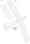 |
J.Herris - Friedrichshafen Aircraft of WWI /Centennial Perspective/ (21)
|
| G.II
|
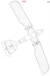 |
J.Herris - Friedrichshafen Aircraft of WWI /Centennial Perspective/ (21)
|
| G.II
|
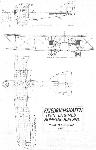 |
Журнал - Flight за 1917 г.
|
|
|
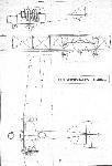 |
Журнал - Flight за 1918 г.
|
| General arrangement drawings of the Friedrichshafen bomber.
|
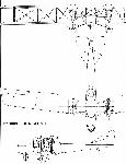 |
A.Imrie - German Bombers /Arms & Armour/
|
| Friedrichshafen Type G.III
|
 |
В.Кондратьев - Самолеты первой мировой войны
|
| "Фридрихсхафен" G-III
|