Описание
Страна: Германия
Год: 1915
Two-seat reconnaissance and general duties
Варианты
- Euler - B.II - 1914 - Германия
- LVG - B.I - 1914 - Германия
- LVG - B.II - 1914 - Германия
- LVG - C.I - 1915 - Германия
- LVG - C.II - 1915 - Германия
- LVG - C.III - 1915 - Германия
- LVG - C.IV - 1916 - Германия
- LVG - B.III / C.XI(Shul) - 1917 - Германия
- В.Кондратьев Самолеты первой мировой войны
- O.Thetford, P.Gray German Aircraft of the First World War (Putnam)
- J.Herris LVG Aircraft of WWI. Vol.1: B-Types & C.I (A Centennial Perspective on Great War Airplanes 34)
- M.Dusing German Aviation Industry in WWI. Volume 1 (A Centennial Perspective on Great War Airplanes 84)
-

J.Herris - LVG Aircraft of WWI. Volume 1: B-Types & C.I /Centennial Perspective/ (34)
LVG C.I 289/15 of an unknown unit circa 1915/16. The decorated wheel covers are a unit or personal marking.
-

J.Herris - LVG Aircraft of WWI. Volume 1: B-Types & C.I /Centennial Perspective/ (34)
LVG C.I 316/15 of Flieger Ersatz Abteilung 3, the flying school at the Gotha. The inscription above the serial reads: "Flieg. Ers. Abt. 3, Gotha Telef 1040" and includes the telephone number as well as stating that it belongs to FEA3 at Gotha.
-

J.Herris - LVG Aircraft of WWI. Volume 1: B-Types & C.I /Centennial Perspective/ (34)
LVG C.I 323/15 of an unknown unit.
-

J.Herris - LVG Aircraft of WWI. Volume 1: B-Types & C.I /Centennial Perspective/ (34)
LVG C.I L.F.143b flown by Lt. Wilhelm Mattheu and Lt.Theo Osterkamp of M.F.Fl.Abt. 1, September 1916.
-

J.Herris - LVG Aircraft of WWI. Volume 1: B-Types & C.I /Centennial Perspective/ (34)
LVG C.I flown by Lt. Hans von Trotha and Lt. Rolf von Lersner of Kagohl 1, Staffel 4.
-

J.Herris - LVG Aircraft of WWI. Volume 1: B-Types & C.I /Centennial Perspective/ (34)
LVG C.I with diagonal stripe markings on the fuselage, ca. 1915. The stripes may indicate a Bavarian unit. The engine, exhaust, and magazine for the Parabellum are non-standard.
-

J.Herris - LVG Aircraft of WWI. Volume 1: B-Types & C.I /Centennial Perspective/ (34)
LVG C.I C.154/15 running up its engine. The LVG C.I was developed from the LVG B.I; it can be distinguished from the C.II by the side radiators and angled fuselage seam between the fabric and plywood. (Peter M. Grosz Collection/STDB)
-

J.Herris - LVG Aircraft of WWI. Volume 1: B-Types & C.I /Centennial Perspective/ (34)
Max Immelmann poses in and out of the cockpit of an LVG C.I that was probably 162/15 - the plane in which Oswald Boelcke achieved his first victory and was later passed on to Immelmann.
-

J.Herris - LVG Aircraft of WWI. Volume 1: B-Types & C.I /Centennial Perspective/ (34)
LVG C.I 164/15 at Johannisthal. (Peter M. Grosz Collection/STDB)
-

J.Herris - LVG Aircraft of WWI. Volume 1: B-Types & C.I /Centennial Perspective/ (34)
LVG C.I 170/15 waits for its next flight. (Peter M. Grosz Collection/STDB)
-

J.Herris - LVG Aircraft of WWI. Volume 1: B-Types & C.I /Centennial Perspective/ (34)
LVG C.I 174/15 next to the airship hangars at Adlershof still uses side radiators. (Peter M. Grosz Collection/STDB)
-

J.Herris - LVG Aircraft of WWI. Volume 1: B-Types & C.I /Centennial Perspective/ (34)
LVG C.I 289/15 with its flight crew and other men of the Abteilung. (Reinhard Zankl)
-

J.Herris - LVG Aircraft of WWI. Volume 1: B-Types & C.I /Centennial Perspective/ (34)
LVG C.I 298/15. This photo has been damaged and the upper right wingtip has been obscured.
-

J.Herris - LVG Aircraft of WWI. Volume 1: B-Types & C.I /Centennial Perspective/ (34)
LVG C.I 316/15 bears the small fuselage inscription "Flieg. Ers.Abt. 3 Gotha Telef 1040" indicating the aircraft is assigned to FEA 3 at Gotha and gives its phone number. Under the serial is the number 1080; was this the work number? (Reinhard Zankl)
-

J.Herris - LVG Aircraft of WWI. Volume 1: B-Types & C.I /Centennial Perspective/ (34)
LVG C.I 323/15 was beautifully-finished and sported a leading-edge radiator, which was less vulnerable than earlier radiators on the fuselage sides and generated less drag. With the fine finish and leading-edge radiator it appears much more modern than LVG C.I 154/15. (Peter M. Grosz Collection/STDB)
-

J.Herris - LVG Aircraft of WWI. Volume 1: B-Types & C.I /Centennial Perspective/ (34)
LVG B.I B.1123/15 is marked on the rudder; number 108 and on the fin and serial 108_/15 is on the fuselage side. There is a gun turret in the rear position and side radiators. This aircraft appears to be a B.I converted to C.I configuration, likely during development of the C.I. Or was the rudder with B-type serial salvaged from an earlier aircraft? (Peter M. Grosz Collection/STDB)
-

J.Herris - LVG Aircraft of WWI. Volume 1: B-Types & C.I /Centennial Perspective/ (34)
LVG C.I in front of the Parseval airship hangar at Johannisthal. (Peter M. Grosz Collection/STDB)
-

J.Herris - LVG Aircraft of WWI. Volume 1: B-Types & C.I /Centennial Perspective/ (34)
LVG C.I attached to FFA 61. (Bruno Schmaling)
-

J.Herris - LVG Aircraft of WWI. Volume 1: B-Types & C.I /Centennial Perspective/ (34)
LVG C.I with leading-edge radiator.
-

J.Herris - LVG Aircraft of WWI. Volume 1: B-Types & C.I /Centennial Perspective/ (34)
LVG C.I L.F.143b was assigned to the Navy. Both air and ground crew pose both pose with it before a flight. The tall observer on the right holding a camera is Theo Osterkamp, who became the highest-scoring German naval ace. The pilot next to him is Lt. Wilhelm Mattheus; both were serving in Marine Feldflieger-Abteilung 1 at this time. In this very aircraft, on 6 September 1916, this crew put in a claim for a Farman shot down. In spite of supporting witness statements, most accounts do not credit Osterkamp with what would have been his first victory on this date - though others indicate he might have been credited with it by some authorities. Mattheus also became a fighter pilot in MFJ I, received the Hohenzollern House Order, but died from wounds in late 1917. (Peter M. Grosz Collection/STDB)
-

A.Imrie - German Naval Air Service /Arms & Armour/
Two-seater crew of an LVG C I of Il Marine Feldflieger-Abteilung at Mariakerke in Flanders. The observer at right with the 25cm hand-held camera is Leutnant Theo Osterkamp, who later became one of the top-scoring naval fighter plilots; he was credited with 31 victories and was awarded Germany's highest military decoration, the Ordre Pour le Merite on 2 September 1918.
-

J.Herris - LVG Aircraft of WWI. Volume 1: B-Types & C.I /Centennial Perspective/ (34)
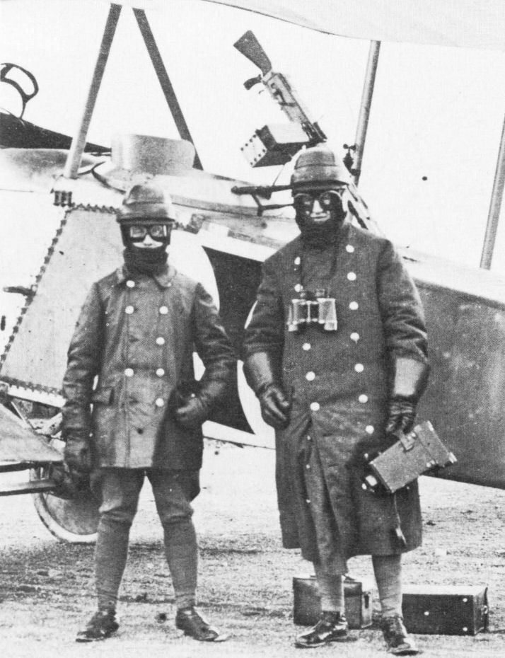
The observer of an LVG C.I demonstrates his weapon.
-

J.Herris - LVG Aircraft of WWI. Volume 1: B-Types & C.I /Centennial Perspective/ (34)
LVG C.I of FFA 6b with individual marking. The personal marking on the C.I of FFA 6b is a somewhat faded Bavarian Lion. (Bruno Schmaling)
-

J.Herris - LVG Aircraft of WWI. Volume 1: B-Types & C.I /Centennial Perspective/ (34)
LVG C.I of FFA 6b with Bavarian Lion insignia. (Reinhard Zankl)
-

J.Herris - LVG Aircraft of WWI. Volume 1: B-Types & C.I /Centennial Perspective/ (34)
LVG C.I with light and dark fuselage stripes, likely a unit marking. (Reinhard Zankl)
-

J.Herris - LVG Aircraft of WWI. Volume 1: B-Types & C.I /Centennial Perspective/ (34)
This LVG C.I has been modified with a fixed Parabellum LMG 14 mounted over the wing for the pilot. The clip to secure the flexible gun when not in use is evident behind the observer. (Peter M. Grosz Collection/STDB)
-

-

J.Herris - LVG Aircraft of WWI. Volume 1: B-Types & C.I /Centennial Perspective/ (34)
This Parabellum LMG 14 may be the same one that was usually fitted to the observer's gun ring, and could be dismounted and re-mounted on this fitting allowing the observer to fire it forward and upwards.
-

J.Herris - LVG Aircraft of WWI. Volume 1: B-Types & C.I /Centennial Perspective/ (34)
Although this LVG C.I had a Schneider gun ring as usual, it has been fitted with an improvised mounting bracket on the interplane struts that allowed the Parabellum LMG 14 to be lifted off the gun ring and dropped into the bracket to fire forwards and upwards. The gun mounted on the side is a Mauser carbine (Model 15). The gun ring has a backrest (perhaps armored) but this was soon abandoned. Fl. Abt. 23, Roupy Aerodrome. (Greg VanWyngarden)
-

M.Dusing - German Aviation Industry in WWI. Volume 2 /Centennial Perspective/ (85)
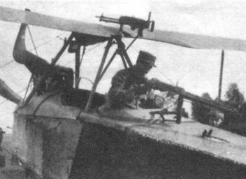
Turret for the movable MG in LVG two-seater C-airplane.
-

J.Herris - LVG Aircraft of WWI. Volume 1: B-Types & C.I /Centennial Perspective/ (34)
Close-up of another LVG C.I with a Schneider gun ring with a backrest (perhaps armored) but this was soon abandoned. (Greg VanWyngarden)
-

J.Herris - LVG Aircraft of WWI. Volume 1: B-Types & C.I /Centennial Perspective/ (34)
LVG C.I of MA 206 at Johannisthal. (Bruno Schmaling)
-

J.Herris - LVG Aircraft of WWI. Volume 1: B-Types & C.I /Centennial Perspective/ (34)
Closeup of an LVG C.I. (Reinhard Zankl)
-

J.Herris - LVG Aircraft of WWI. Volume 1: B-Types & C.I /Centennial Perspective/ (34)
LVG C.I piloted by Lt. Hans Ulrich von Trotha. The observer, Lt. Rolf Freiherr von Lersner, is waving to the camera. The "IV.1" legend on the fuselage indicates Kampfstaffel 4 (Kagohl 1), machine 1. The black and yellow bands on the fuselage were an addition, in the von Trotha family colors. Von Trotha was later the Executive Officer of the Gotha G.IV-equipped England Geschwader that bombed London. (Greg VanWyngarden)
-

J.Herris - LVG Aircraft of WWI. Volume 1: B-Types & C.I /Centennial Perspective/ (34)
LVG C.I photographed from another aircraft in flight.
-

-

-

J.Herris - LVG Aircraft of WWI. Volume 1: B-Types & C.I /Centennial Perspective/ (34)
LVG C.I 36/15 after a bad landing in the snow.
-

J.Herris - LVG Aircraft of WWI. Volume 1: B-Types & C.I /Centennial Perspective/ (34)
LVG C.I 37/15 after a landing accident at FEA 4 at Posen. The poor field condition is obvious. (Bruno Schmaling)
-

J.Herris - LVG Aircraft of WWI. Volume 1: B-Types & C.I /Centennial Perspective/ (34)
Three photos of the crash of LVG C.I C.155/15 of FFA 6b. (Bruno Schmaling)
В.Кондратьев Самолеты первой мировой войны
LVG B-I/B-II/C-I/C-II/C-III/C-IV
В 1912 году швейцарский инженер Франц Шнейдер стал главным конструктором новой немецкой фирмы Люфт-Веркерс Гезельшафт - LVG (Компания воздушного транспорта). Созданный им биплан D IV показал блестящие результаты в авиационных состязаниях и совершил ряд дальних перелетов.
В 1914 году эту машину под индексом B-I приняли на вооружение германских ВВС. В течение последующих двух лет на ее базе создан целый ряд модификаций, также строившихся серийно, состоявших на вооружении и принимавших участие в боевых действиях.
МОДИФИКАЦИИ
C-I - первый в мире аэроплан, оснащенный кольцевой пулеметной турелью Шнейдера, ставшей в дальнейшем стандартной огневой установкой для всех немецких многоместных боевых машин. Двигатель "Бенц", 150 л.с.
ВООРУЖЕНИЕ
1 турельный "Парабеллум" на всех С-модификациях.
Описание: