Описание
Страна: Германия
Год: 1917
Light two-seat C type, escort and ground attack
Варианты
- Halberstadt - CL.II/CL.IIa - 1917 - Германия
- Halberstadt - CL.IV - 1918 - Германия
- В.Кондратьев Самолеты первой мировой войны
- O.Thetford, P.Gray German Aircraft of the First World War (Putnam)
- W.Green, G.Swanborough The Complete Book of Fighters
- J.Herris Halberstadt Aircraft of WWI. Volume 1: A-types to C.III (A Centennial Perspective on Great War Airplanes 44)
- J.Herris Halberstadt Aircraft of WWI. Volume 2: CL.IV-CLS.I & Fighters (A Centennial Perspective on Great War Airplanes 45)
- M.Dusing German Aviation Industry in WWI. Volume 1 (A Centennial Perspective on Great War Airplanes 84)
- M.Kabatek, Fr.R.Kulczynski German Aircraft in Polish Service. Volume 1
- Журнал Flight
-

J.Herris - Halberstadt Aircraft of WWI. Volume 1: A-types to C.III /Centennial Perspective/ (44)
Halberstadt CL.II 14258/17, Seefrosta, March 1918
-

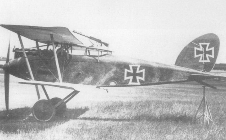
J.Herris - Halberstadt Aircraft of WWI. Volume 1: A-types to C.III /Centennial Perspective/ (44)
Halberstadt CL.II 15459/17 assigned to GenLt. Ernst von Hoeppner
-

J.Herris - Halberstadt Aircraft of WWI. Volume 1: A-types to C.III /Centennial Perspective/ (44)
Halberstadt CL.II(BFW) 785/18
-

J.Herris - Halberstadt Aircraft of WWI. Volume 1: A-types to C.III /Centennial Perspective/ (44)
Halberstadt CL.II '4' of Schlasta 2
-

Сайт - Pilots-and-planes /WWW/
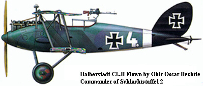
Halberstadt CL.II Flown by Oblt Oscar Bechtle, Commander of Schlachtstaffel 2
-

J.Herris - Halberstadt Aircraft of WWI. Volume 1: A-types to C.III /Centennial Perspective/ (44)
Halberstadt CL.II '5' of Schlasta 5
-

J.Herris - Halberstadt Aircraft of WWI. Volume 1: A-types to C.III /Centennial Perspective/ (44)
Halberstadt CL.II '6' of Schlasta 5
-

J.Herris - Halberstadt Aircraft of WWI. Volume 1: A-types to C.III /Centennial Perspective/ (44)
Halberstadt CL.II '6' of Schlasta 6
-

J.Herris - Halberstadt Aircraft of WWI. Volume 1: A-types to C.III /Centennial Perspective/ (44)
Halberstadt CL.II '6' of Schlasta 7
-

J.Herris - Halberstadt Aircraft of WWI. Volume 1: A-types to C.III /Centennial Perspective/ (44)
Halberstadt CL.II of Schlasta 11
-

J.Herris - Halberstadt Aircraft of WWI. Volume 1: A-types to C.III /Centennial Perspective/ (44)
Halberstadt CL.II '13' of Schlasta 12
-

J.Herris - Halberstadt Aircraft of WWI. Volume 1: A-types to C.III /Centennial Perspective/ (44)
Halberstadt CL.II of Schlasta 12
-

J.Herris - Halberstadt Aircraft of WWI. Volume 1: A-types to C.III /Centennial Perspective/ (44)
Halberstadt CL.II '1' of Schlasta 19
-

J.Herris - Halberstadt Aircraft of WWI. Volume 1: A-types to C.III /Centennial Perspective/ (44)
Halberstadt CL.II '2' of Schlasta 21
-

J.Herris - Halberstadt Aircraft of WWI. Volume 1: A-types to C.III /Centennial Perspective/ (44)
Halberstadt CL.II '3' Martha of Schlasta 21
-

В.Кондратьев - Самолеты первой мировой войны
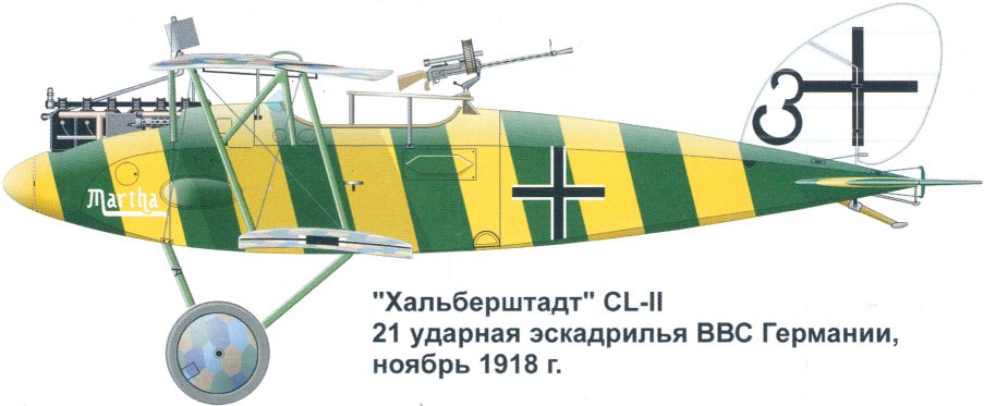
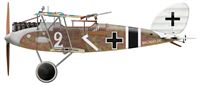
"Хальберштадт" CL-II, 21 ударная эскадрилья ВВС Германии, ноябрь 1918г.
-

J.Herris - Halberstadt Aircraft of WWI. Volume 1: A-types to C.III /Centennial Perspective/ (44)
Halberstadt CL.II '4' of Schlasta 23
-

J.Herris - Halberstadt Aircraft of WWI. Volume 1: A-types to C.III /Centennial Perspective/ (44)
Halberstadt CL.II '5' of Schlasta 24
-

J.Herris - Halberstadt Aircraft of WWI. Volume 1: A-types to C.III /Centennial Perspective/ (44)
Halberstadt CL.II '4' of Schlasta 25
-

J.Herris - Halberstadt Aircraft of WWI. Volume 1: A-types to C.III /Centennial Perspective/ (44)
Halberstadt CL.II '4' of Schlasta 26
-

J.Herris - Halberstadt Aircraft of WWI. Volume 1: A-types to C.III /Centennial Perspective/ (44)
Halberstadt CL.II '6' of Schlasta 26
-

J.Herris - Halberstadt Aircraft of WWI. Volume 1: A-types to C.III /Centennial Perspective/ (44)
Halberstadt CL.II '1' of Schlasta 27
-

J.Herris - Halberstadt Aircraft of WWI. Volume 1: A-types to C.III /Centennial Perspective/ (44)
Halberstadt CL.II '1' Anni of Schlasta 27
-

J.Herris - Halberstadt Aircraft of WWI. Volume 1: A-types to C.III /Centennial Perspective/ (44)
Halberstadt CL.II '2' Brunhilde of Schlasta 27b
-
J.Herris - Development of German Warplanes in WWI /Centennial Perspective/ (1)
Brunhilde in color. The standard factory camouflage is used with the unit markings of white chevron, white vertical tail, black and white fuselage and tailplane stripes. The tactical number and girlfriend's name were added in white to individualize each aircraft. In this case the tactical number was '2' and the girlfriend was Brunhilde.
-

J.Herris - Halberstadt Aircraft of WWI. Volume 1: A-types to C.III /Centennial Perspective/ (44)
Halberstadt CL.II '5' Thea of Schlasta 27
-

J.Herris - Halberstadt Aircraft of WWI. Volume 1: A-types to C.III /Centennial Perspective/ (44)
Halberstadt CL.II of Schlasta 29b, Gefr. Wilhelm Kreiger, September 1918
-

J.Herris - Halberstadt Aircraft of WWI. Volume 1: A-types to C.III /Centennial Perspective/ (44)
Halberstadt CL.II of Schlasta 31b, May 1918
-

J.Herris - Halberstadt Aircraft of WWI. Volume 1: A-types to C.III /Centennial Perspective/ (44)
Halberstadt CL.II '2' of Schlasta 33
-

J.Herris - Halberstadt Aircraft of WWI. Volume 1: A-types to C.III /Centennial Perspective/ (44)
Halberstadt CL.II '1' of Schlasta 35
-

J.Herris - Halberstadt Aircraft of WWI. Volume 1: A-types to C.III /Centennial Perspective/ (44)
Halberstadt CL.II "Halbe Portion" of an unknown unit.
-

-

В.Обухович, А.Никифоров - Самолеты Первой Мировой войны
Хальберштадт CL II
-

M.Kabatek, Fr.R.Kulczynski - German Aircraft in Polish Service. Volume 1 /Aeronaut/
Halberstadt Cl.II (Bay) 781/18 (Polish serial 201/18) of III Eskadra Wielkopolska, flown by ppor. pil. Jozef Manczak and kpr. obs. Jozef Klicze, Velyka Berezovytsia, August 1919
-

J.Herris - Halberstadt Aircraft of WWI. Volume 1: A-types to C.III /Centennial Perspective/ (44)
Halberstadt CL.II(BFW) 785/18
-

M.Kabatek, Fr.R.Kulczynski - German Aircraft in Polish Service. Volume 1 /Aeronaut/
Halberstadt Cl.II (Bay) 782/18 (Polish serial 202/18) of Szkola Pilotow, Poznan-Lawica, summer 1919.
-

M.Kabatek, Fr.R.Kulczynski - German Aircraft in Polish Service. Volume 1 /Aeronaut/
Halberstadt Cl.II (Polish serial 203/18) of Szkola Pilotow, Poznan-Lawica, March 1919
-

M.Kabatek, Fr.R.Kulczynski - German Aircraft in Polish Service. Volume 1 /Aeronaut/
Halberstadt Cl.II (Bay) 753/18 (Polish serial 208/18) of Szkola Pilotow, Poznan-Lawica, summer 1919
-

M.Kabatek, Fr.R.Kulczynski - German Aircraft in Polish Service. Volume 1 /Aeronaut/
Halberstadt Cl.II (Bay) 2869/18 (Polish serial 223/18) of Wyzsza Szkola Pilotow, flown by ppor. pil. Jozef Szyfter, Poznan-Lawica, summer 1920
-

M.Kabatek, Fr.R.Kulczynski - German Aircraft in Polish Service. Volume 1 /Aeronaut/
Halberstadt Cl.II (Bay) 2875/18 of III Eskadra Wielkopolska, flown by pplk. pil. Marek Krzyczkowski and st. szer. obs. Jozef Klicze, Gora, June 1919
-

J.Herris - Halberstadt Aircraft of WWI. Volume 1: A-types to C.III /Centennial Perspective/ (44)
Halberstadt CL.II prototype. (Peter M. Grosz collection/STDB)
-

J.Herris - Halberstadt Aircraft of WWI. Volume 1: A-types to C.III /Centennial Perspective/ (44)
Halberstadt CL.II prototype. (Peter M.Grosz collection/STDB)
-

J.Herris - Halberstadt Aircraft of WWI. Volume 1: A-types to C.III /Centennial Perspective/ (44)
Additional views of the Halberstadt CL.II prototypes. The below photo shows the machine is now covered on top and sides in two-tone camouflage, very probably light and dark green. (Peter M. Grosz collection/STDB)
-

J.Herris - Halberstadt Aircraft of WWI. Volume 1: A-types to C.III /Centennial Perspective/ (44)
The photo shows the machine is now covered on top and sides in two-tone camouflage, very probably light and dark green. (Peter M. Grosz collection/STDB)
Believed to be the second prototype, this Cl.II has a smaller wing span and possibly a larger wing gap (at least three different wing strut length were tested). -

J.Herris - Halberstadt Aircraft of WWI. Volume 1: A-types to C.III /Centennial Perspective/ (44)
Halberstadt Cl.II 9902/16 prototype during the course of Typenprufung, May 2-7 1917 at the Adlershof test centre.
-

J.Herris - Halberstadt Aircraft of WWI. Volume 1: A-types to C.III /Centennial Perspective/ (44)
Additional views of the Halberstadt CL.II prototype. (Peter M. Grosz collection/STDB)
-

J.Herris - Halberstadt Aircraft of WWI. Volume 1: A-types to C.III /Centennial Perspective/ (44)
This may be the third prototype Cl.II 9902/16 (w/n 353) on the factory airfield in May 1917.
-

J.Herris - Halberstadt Aircraft of WWI. Volume 1: A-types to C.III /Centennial Perspective/ (44)
Additional views of the Halberstadt CL.II prototype. The upper wing is in one piece. (Peter M. Grosz collection/STDB)
-

J.Herris - Halberstadt Aircraft of WWI. Volume 1: A-types to C.III /Centennial Perspective/ (44)
Halberstadt CL.II prototype photographed in May 1917. (Peter M. Grosz collection/STDB)
-

J.Herris - Halberstadt Aircraft of WWI. Volume 1: A-types to C.III /Centennial Perspective/ (44)
Prototype Halberstadt CL.II wearing typical Halberstadt speckled camouflage on upper surfaces. The one-piece upper wing is of shorter span and the rear turret has been removed to make room for flight test instrumentation. (Peter M. Grosz collection/STDB)
-

J.Herris - Halberstadt Aircraft of WWI. Volume 1: A-types to C.III /Centennial Perspective/ (44)
Prototype Halberstadt CLII wearing Halberstadt camouflage. The rear turret has been removed to make room for flight test instrumentation. (Peter M. Grosz collection/STDB)
-

J.Herris - Halberstadt Aircraft of WWI. Volume 1: A-types to C.III /Centennial Perspective/ (44)
Prototype Halberstadt CLII wearing Halberstadt camouflage. The rear turret has been removed to make room for flight test instrumentation. (Peter M. Grosz collection/STDB)
-

J.Herris - Halberstadt Aircraft of WWI. Volume 1: A-types to C.III /Centennial Perspective/ (44)
Halberstadt Cl.II prototype with one-piece upper wing of shorter span
An early Halberstadt CL.II wearing the Halberstadt-factory colors of the time. The undersurfaces of the wings, tail, and fuselage were not camouflaged in dark colors. (Peter M. Grosz collection/STDB) -

J.Herris - Halberstadt Aircraft of WWI. Volume 1: A-types to C.III /Centennial Perspective/ (44)
An early Halberstadt CL.II wearing the Halberstadt-factory colors of the time applied to the upper surfaces and sides. (Peter M. Grosz collection/STDB)
-

J.Herris - Halberstadt Aircraft of WWI. Volume 1: A-types to C.III /Centennial Perspective/ (44)
Production Halberstadt Cl.II prototype fitted with a two-piece upper wing of enlarged span.
Halberstadt CL II at Adlershof for type test in May 1917. -

J.Herris - Halberstadt Aircraft of WWI. Volume 1: A-types to C.III /Centennial Perspective/ (44)
More views of an early Halberstadt CL.II wearing the Halberstadt-factory colors of the time. (Peter M. Grosz collection/STDB)
-

J.Herris - Halberstadt Aircraft of WWI. Volume 1: A-types to C.III /Centennial Perspective/ (44)
An early Halberstadt CL.II wearing the Halberstadt-factory colors of the time. The undersurfaces of the wings, tail, and fuselage were not camouflaged in dark colors. (Peter M. Grosz collection/STDB)
-

J.Herris - Halberstadt Aircraft of WWI. Volume 1: A-types to C.III /Centennial Perspective/ (44)
Halberstadt Cl.II 9902/16 prototype during the course of Typenprufung, May 2-7 1917 at the Adlershof test centre.
-

J.Herris - Halberstadt Aircraft of WWI. Volume 1: A-types to C.III /Centennial Perspective/ (44)
An early Halberstadt CL.II wearing the Halberstadt-factory colors of the time applied to the upper surfaces and sides. (Peter M. Grosz collection/STDB)
-

J.Herris - Halberstadt Aircraft of WWI. Volume 1: A-types to C.III /Centennial Perspective/ (44)
Additional views of the early Halberstadt CL.II at the Fokker airfield. (Peter M. Grosz collection/STDB)
-

J.Herris - Halberstadt Aircraft of WWI. Volume 1: A-types to C.III /Centennial Perspective/ (44)
An early Halberstadt CL.II visiting the Fokker airfeld at Schwerin-Gorries. A Fokker employee is holding a meter stick on the fuselage so it can be photographed in scale. There is a lack of factory-applied identification markings that was typical of Halberstadt-built aircraft. This machine had a typical finish for early batches of Halberstadt factory camouflage. The fabric on the sides and top was five-color light printed pattern (the lozenge fabric production from Augsburger Kattun Fabric in Augsburg (Augsburg Cotton factory) was started from that light pattern so many factories start covering aeroplanes from that light pattern, then used normal pattern on the undersides). The fuselage speckled camouflage was applied over large lozenges from colors similar to printed lozenge light pattern. The bottom of the fuselage remained in light yellow primer. Similarly the bottom part of wings and tail were covered in unpainted, clear lacquered fabric. (Peter M. Grosz collection/STDB)
-

-

J.Herris - Halberstadt Aircraft of WWI. Volume 1: A-types to C.III /Centennial Perspective/ (44)
Additional views of the early Halberstadt CL.II at the Fokker airfield. (Peter M. Grosz collection/STDB)
-

Сайт - Pilots-and-planes /WWW/
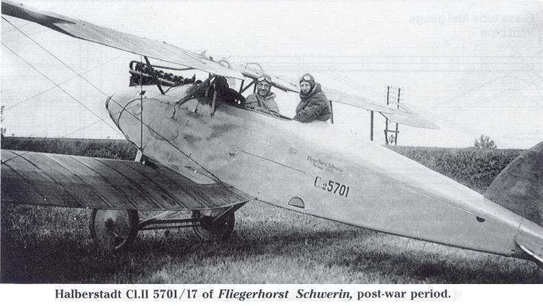
Halberstadt CLII 5701/17 was part of the first production batch. Here it is unarmed and part of Fliegerhorst Schwerin, a para-military police unit immediately postwar.
-

J.Herris - Halberstadt Aircraft of WWI. Volume 1: A-types to C.III /Centennial Perspective/ (44)
Early production Halberstadt CL.II C.5710/17 of an unknown unit. A fragment of the personal badge is seen on the fuselage just forward of the cross. (Peter M. Grosz collection/STDB)
-

J.Herris - Halberstadt Aircraft of WWI. Volume 1: A-types to C.III /Centennial Perspective/ (44)
Early production Halberstadt CL.II C.5710/17 of Schlasta 5. A fragment of the personal badge is seen on the fuselage just forward of the cross. (Peter M. Grosz collection/STDB)
-

J.Herris - Halberstadt Aircraft of WWI. Volume 1: A-types to C.III /Centennial Perspective/ (44)
Halberstadt CL.II 5720/17 tactical #3, with the names Else and Martha, after the armistice in the hands of the 22nd US Aero Squadron. This aircraft was believed to be marked with a yellow-blue or yellow-green spiral painted over the fuselage.The old black-white striped Schlasta 21 markings are still visible under the new paint. Wings from the top painted yellow with darkener (blue or green) outline. Interesting are the different sizes cockades patches at wing bullet holes. (lower photo Peter M. Grosz collection/STDB)
-

J.Herris - Halberstadt Aircraft of WWI. Volume 1: A-types to C.III /Centennial Perspective/ (44)
More views of Halberstadt CL.II 5720/17 tactical #3, with the names Else and Martha, after the armistice in the hands of the 22nd US Aero Squadron.
-

-

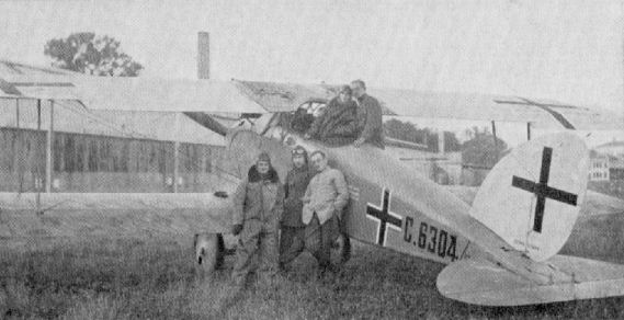
O.Thetford, P.Gray - German Aircraft of the First World War /Putnam/
Halberstadt CL II (serial C 6304/17).
-

J.Herris - Halberstadt Aircraft of WWI. Volume 1: A-types to C.III /Centennial Perspective/ (44)
Halberstadt CL.II 6315/17 of Schultzstaffel 11 was interned in the Netherlands on 31 December 1917 at Ijendijke.The pilot was Unteroffizier Friedrich Carl Reichel. The wings have been removed; the two fuselage bands were unit markings. (Peter M. Grosz collection/STDB)
-

J.Herris - Halberstadt Aircraft of WWI. Volume 1: A-types to C.III /Centennial Perspective/ (44)
Halberstadt CL.II 6315/17 in Netherlands' national markings of the orange circle. It is in Dutch markings after landing in the Netherlands. Given the LVA serial H414 M160, it survived until at least 1919. It fitted with a dynamo. The upper wings still have traces of the Schusta 14 (?) chevron marking. (Peter M. Grosz collection/STDB)
-

J.Herris - Halberstadt Aircraft of WWI. Volume 1: A-types to C.III /Centennial Perspective/ (44)
Halberstadt CL.II 14207/17 '3' of Schlasta 2 was fitted with a dynamo. The aircraft is in factory finish and 1917 insignia. The work number of 678 is visible on the struts. Above the wooden saw horse under the tail is stenciled hier stutzen (support here) in white letters. (Peter M. Grosz collection/STDB)
-

J.Herris - Halberstadt Aircraft of WWI. Volume 1: A-types to C.III /Centennial Perspective/ (44)
Halberstadt CL.II 14219/17 fitted with a dynamo in 1918 markings and new post repair camouflage. (Peter M. Grosz collection/STDB)
-

J.Herris - Halberstadt Aircraft of WWI. Volume 1: A-types to C.III /Centennial Perspective/ (44)
Halberstadt CL.II 14252/17 of Marine Feld Jasta 2e was operating without a spinner when it came down and was interned in the Netherlands on 2 April 1918. The fuselage crosses had been changed to the straight sided version but the curved crosses on the wings were not altered. (Peter M. Grosz collection/STDB)
-

J.Herris - Halberstadt Aircraft of WWI. Volume 1: A-types to C.III /Centennial Perspective/ (44)
Bearing the Netherlands orange circle insignia and LVA Serial H415 is CL.II 14252/17, after being interned. (Peter M. Grosz collection/STDB)
-

J.Herris - Halberstadt Aircraft of WWI. Volume 1: A-types to C.III /Centennial Perspective/ (44)
Bearing the Netherlands orange circle insignia and LVA Serial H415 is CL.II 14252/17, after being interned. (Peter M. Grosz collection/STDB)
-

J.Herris - Halberstadt Aircraft of WWI. Volume 1: A-types to C.III /Centennial Perspective/ (44)
On March 24, 1918, Halberstadt CL.II (C14258/17) was loaned to the Seefrosta by the II.Naval Feldflieger Abteilung due to an acute lack of airworthy aircraft. (KMF)
-

J.Herris - Halberstadt Aircraft of WWI. Volume 1: A-types to C.III /Centennial Perspective/ (44)
Halberstadt CL.II aircraft after coming down in Allied lines. This is probably 15342/17. (Peter M. Grosz collection/STDB)
-

J.Herris - Halberstadt Aircraft of WWI. Volume 1: A-types to C.III /Centennial Perspective/ (44)
Halberstadt CL.II 15342/17 (work number 929) soon after being forced down by Lieutenants R.C. Armstrong and F.J. Mart flying an RE8 of Number 3 Squadron, Australian Flying Corps, on June 9, 1918. The German crew of Gefr. Kueslerand Vzfw. Mullenbach of Schlactstaffel 13 were "lost and inexperienced" and quickly surrendered to the RE8 crew, who shepherded them to a landing at Villers Bocage. (Peter M. Grosz collection/STDB)
-

-

J.Herris - Halberstadt Aircraft of WWI. Volume 1: A-types to C.III /Centennial Perspective/ (44)
Halberstadt CL.II 15342/17 (work number 929) flown by Gefr. Kuesler and Vzfw. Mullenbach of Schlachtstaffel 13 were brought down and captured on June 9, 1918 by Lts. Armstrong and Mart of No. 3 Squadron AFC flying an RE8. The stripes on the horizontal tail were the unit marking. The discoloring of the starboard horizontal tailplane is thought to be due to the exhaust and not a different color of the stripes. Two wooden racks for 6 fragmentation bombs each were fitted to the fuselage sides. (Peter M. Grosz collection/STDB)
-

-

J.Herris - Halberstadt Aircraft of WWI. Volume 1: A-types to C.III /Centennial Perspective/ (44)
More views of Halberstadt CL.II 15342/17 (work number 929) flown by Gefr. Hausler and Vzfw. Mullenbach of Schlachtstaffel 13 was brought down and captured on June 9, 1918. The stripes on the horizontal tail were the unit marking. (Peter M. Grosz collection/STDB except middle photo facing page)
-

J.Herris - Halberstadt Aircraft of WWI. Volume 1: A-types to C.III /Centennial Perspective/ (44)
More views of Halberstadt CL.II 15342/17 (work number 929) flown by Gefr. Hausler and Vzfw. Mullenbach of Schlachtstaffel 13 was brought down and captured on June 9, 1918. The stripes on the horizontal tail were the unit marking. (Peter M. Grosz collection/STDB)
-

J.Herris - Halberstadt Aircraft of WWI. Volume 1: A-types to C.III /Centennial Perspective/ (44)
More views of Halberstadt CL.II 15342/17 (work number 929) flown by Gefr. Hausler and Vzfw. Mullenbach of Schlachtstaffel 13 was brought down and captured on June 9, 1918. These photographs show a typical service Halberstadt CL.II in mid-1918. (Peter M. Grosz collection/STDB)
-

-

-

-

J.Herris - Halberstadt Aircraft of WWI. Volume 1: A-types to C.III /Centennial Perspective/ (44)
Halberstadt CL.II 15342/17 (work number 929) flown by Gefr. Hausler and Vzfw. Mullenbach of Schlachtstaffel 13 was brought down and is shown above after British insignia were painted over the German insignia. This aircraft was assigned the capture number G/5Bde/16 and was the subject of two detailed Allied intelligence reports. The stripes on the tailplane were black and white, and the fin and rudder were gray. The fin and rudder may have been painted gray when the original early insignia were converted to 1918 insignia.
-

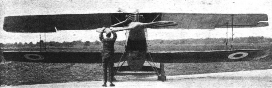
Jane's All The World Aircraft 1919 /Jane's/
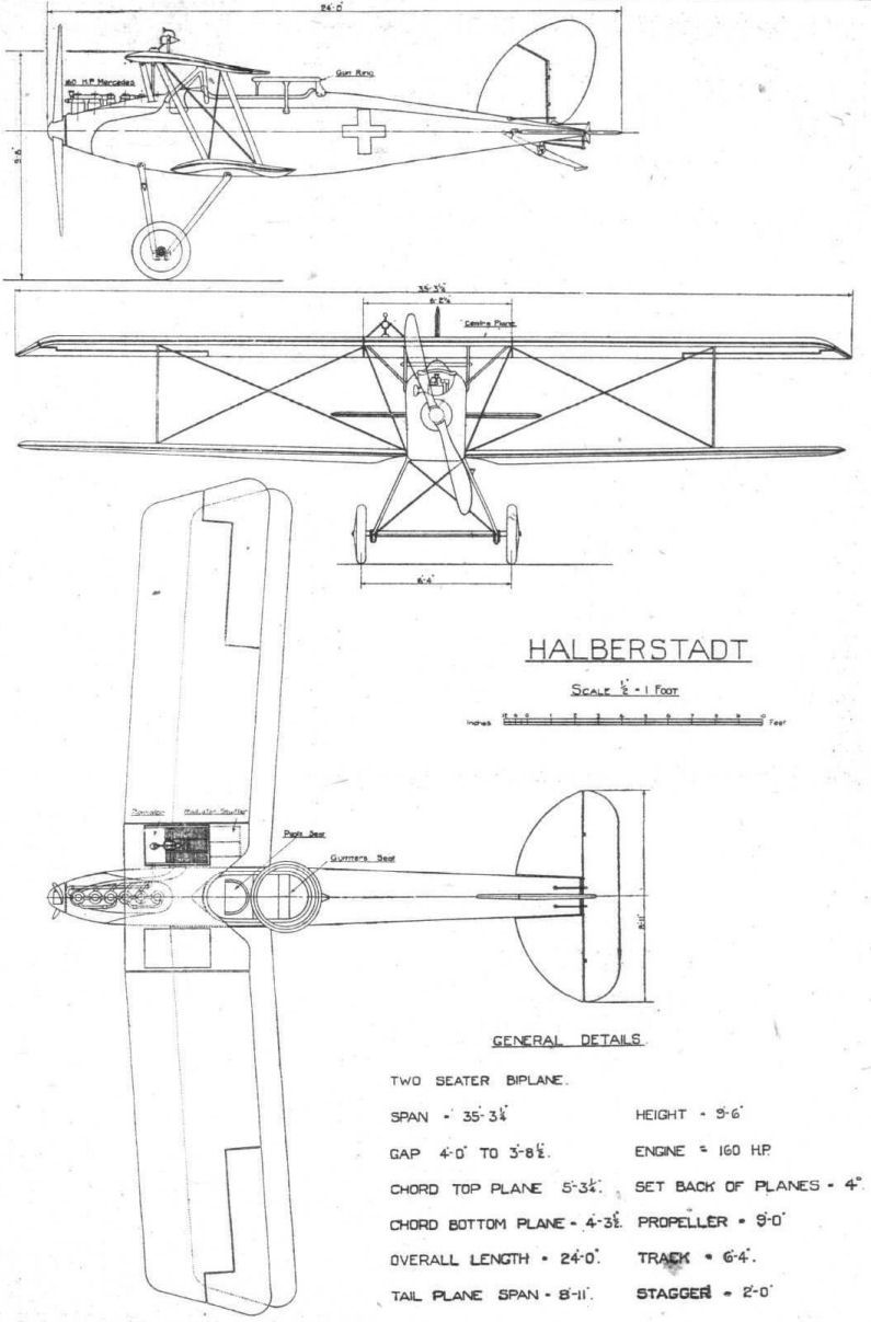
A general view of the Two-seater Halberstadt CL.II.
-

J.Herris - Halberstadt Aircraft of WWI. Volume 1: A-types to C.III /Centennial Perspective/ (44)
Halberstadt CL.II 15342/17 is shown after British insignia were painted over the German insignia.
-

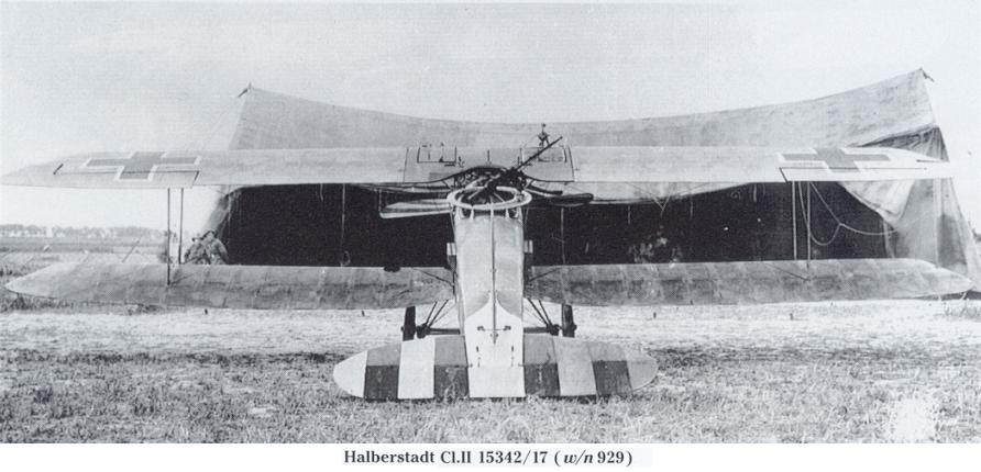
Журнал - Flight за 1918 г.
Front view of the Halberstadt fighter.
-

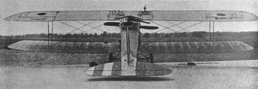
Jane's All The World Aircraft 1919 /Jane's/
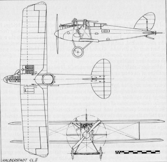
A rear view of the Halberstadt CL.II showing tail plane arrangement.
-

J.Herris - Halberstadt Aircraft of WWI. Volume 1: A-types to C.III /Centennial Perspective/ (44)
Halberstadt CL.II 15342/17 of Schlachtstaffel 13 after false German insignia were painted over the British insignia that were painted over the German insignia. Note the old insignia on the fuselage, the 1918 insignia on the fin and rudder, and the red/white/blue British stripes on the rudder. (Peter M. Grosz collection/STDB)
-

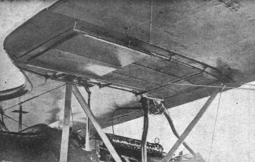
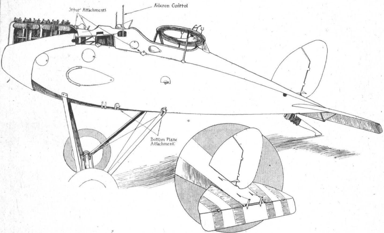
Журнал - Flight за 1918 г.
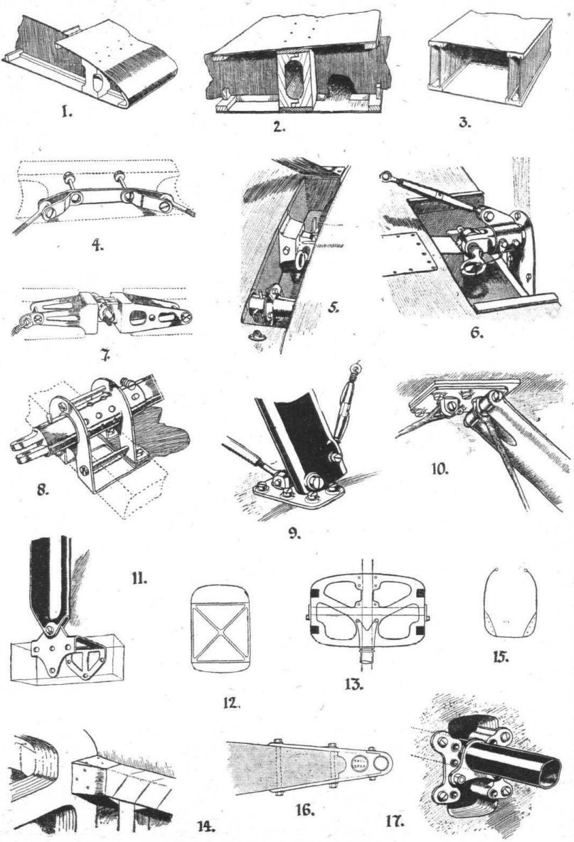
A. View of underside of centre section, showing radiator and shutter, machine gun and cabane struts.
-

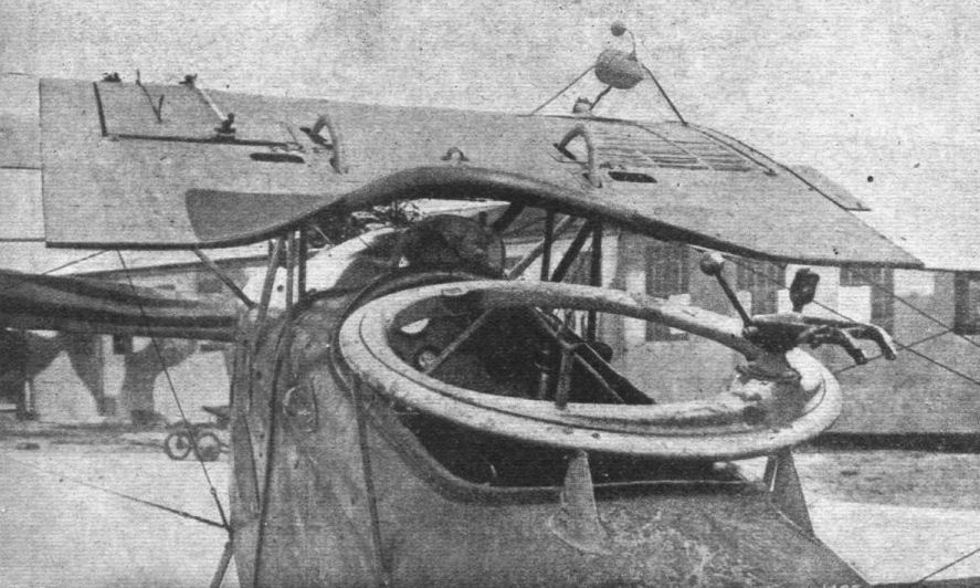
Журнал - Flight за 1918 г.
B. View of cockpits, showing aileron cranks, gun ring, radiator and gravity petrol tank.
-

M.Dusing - German Aviation Industry in WWI. Volume 1 /Centennial Perspective/ (84)
Light combat aircraft Halberstadt CL.II (C.15459/17) in the Berlin Aviation Collection (opening: June 20, 1936).
-

J.Herris - Halberstadt Aircraft of WWI. Volume 1: A-types to C.III /Centennial Perspective/ (44)
An aircrew with their Halberstadt CL.II(Bay) 742/18 in training service.The BFW factory did not apply camouflage to the Halberstadt GLIIs they built although the flying surfaces used camouflage printed fabric. (Peter M. Grosz collection/STDB)
-

J.Herris - Halberstadt Aircraft of WWI. Volume 1: A-types to C.III /Centennial Perspective/ (44)
Halberstadt CLII 785/18 was built under license by BFW. The aircraft has 1918 insignia and no wheel covers. The camouflage, five color, dark pattern, printed fabric is clearly visible on the wings, rudder, and tailplane. The fuselage was finished by reddish-brown shellac. (Peter M. Grosz collection/STDB)
Note vertical "rhino-horn" exhaust pipe. -

J.Herris - Halberstadt Aircraft of WWI. Volume 1: A-types to C.III /Centennial Perspective/ (44)
Halberstadt CLII 785/18 was built under license by BFW. The aircraft has 1918 insignia and no wheel covers. The camouflage, five color, dark pattern, printed fabric is clearly visible on the wings, rudder, and tailplane. The fuselage was finished by reddish-brown shellac. (Peter M. Grosz collection/STDB)
-

J.Herris - Halberstadt Aircraft of WWI. Volume 1: A-types to C.III /Centennial Perspective/ (44)
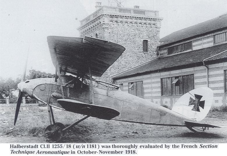
Late production Halberstadt CL.II 1255/18 work no.1181 of an unknown unit with dynamo and without tires that was French war booty. The machine was painstaking examined and reported on by Section Technique Aeronautique. (Peter M. Grosz collection/STDB)
-

Сайт - Pilots-and-planes /WWW/
Halberstadt Cl.II 1255/18 (w/n 1181) was thoroughly evaluated by the French Section Technique Aeronautique in October-November 1918.
-

J.Herris - Halberstadt Aircraft of WWI. Volume 1: A-types to C.III /Centennial Perspective/ (44)
A pilot with his unarmed Halberstadt CL.IIa(Bay) from the C2800-C.2999/18 batch powered by 180 hp Argus As.III engine. Intended for training, this production batch was finished without an observer's gun ring. (Peter M. Grosz collection/STDB)
-

J.Herris - Halberstadt Aircraft of WWI. Volume 1: A-types to C.III /Centennial Perspective/ (44)
Halberstadt CLIIa(Bay) C.2875/18 from Polish 3 Eskadra Wielkopolska. Photo taken in 1919.There is no spinner. (Peter M. Grosz collection/STDB)
-

J.Herris - Halberstadt Aircraft of WWI. Volume 1: A-types to C.III /Centennial Perspective/ (44)
Early Halberstadt CL.II without spinner before insignia was applied. (Peter M. Grosz collection/STDB)
-

J.Herris - Halberstadt Aircraft of WWI. Volume 1: A-types to C.III /Centennial Perspective/ (44)
Halberstadt CL.II '1' of Vzfw. Redenbacher of Schutzstaffel 27b with early insignia over white backgrounds. (Peter M. Grosz collection/STDB)
-

J.Herris - Halberstadt Aircraft of WWI. Volume 1: A-types to C.III /Centennial Perspective/ (44)
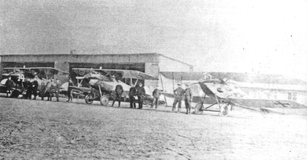
Early production Halberstadt CL.II of an unknown unit in front of its hangar in 1917. (Peter M. Grosz collection/STDB)
-

K.Delve - World War One in the Air /Crowood/
The Halberstadt CLII was one of the types built in 1917 for Schutzstaffeln (escort flights) - a two-seat fighter escort armed with one or two Spandaus plus a parabellum for the observer.
-

J.Herris - Halberstadt Aircraft of WWI. Volume 1: A-types to C.III /Centennial Perspective/ (44)
Aircrew rest near Halberstadt CL.II 14299/17 wk. no. 770 of Oblt. Bechtle, Schutzstaffel 2. The dark (black?) tails are the unit marking. (Peter M. Grosz collection/STDB)
-

J.Herris - Halberstadt Aircraft of WWI. Volume 1: A-types to C.III /Centennial Perspective/ (44)
Halberstadt CL.II of an unknown unit with arrow marking. Bullet holes have been patched with cockade markings.
-

J.Herris - Halberstadt Aircraft of WWI. Volume 1: A-types to C.III /Centennial Perspective/ (44)
Vzfw. Willi Gabriel (with walking stick) and probably Uffz. Hilsebein with their early production Halberstadt CL.II of Schutzstaffel 15 in 1917. The side dynamo is not fitted and blanked by a flat plate, and there are mud guards over the wheels. (Peter M. Grosz collection/STDB)
-

J.Herris - Halberstadt Aircraft of WWI. Volume 1: A-types to C.III /Centennial Perspective/ (44)
The crew of Halberstadt CL.II 'V' of an unknown unit, probably Schutzstaffel 13, pose with their aircraft. (Peter M. Grosz collection/STDB)
-

J.Herris - Halberstadt Aircraft of WWI. Volume 1: A-types to C.III /Centennial Perspective/ (44)
Halberstadt CL.II with a dynamo and with insignia over white backgrounds. The white square painted around the insignia was to hide the arrival of the new type of aircraft to the front. (Peter M. Grosz collection/STDB)
-

J.Herris - Halberstadt Aircraft of WWI. Volume 1: A-types to C.III /Centennial Perspective/ (44)
Halberstadt CL.II of an unknown unit fitted with a dynamo. The whole aircraft has been overpainted a dark color, probably black. (Peter M. Grosz collection/STDB)
The Halberstadt CLII was increasingly used by the 'battle flights' for trench warfare; armed with machine guns, bombs and hand-grenades the aircraft flew very low, attacking ground troops and causing havoc. -

J.Herris - Halberstadt Aircraft of WWI. Volume 1: A-types to C.III /Centennial Perspective/ (44)
Production Halberstadt CL.II tactical #13 of Schusta 12; the gunner has a scope on his machinegun and dynamo for a wireless is fitted. (Peter M. Grosz collection/STDB)
-

J.Herris - Halberstadt Aircraft of WWI. Volume 1: A-types to C.III /Centennial Perspective/ (44)
The aircrew of a Halberstadt CL.II of FI.Abt.(A) 238 photographed with their airplane.
-

J.Herris - Halberstadt Aircraft of WWI. Volume 1: A-types to C.III /Centennial Perspective/ (44)
Early production Halberstadt CL.II of an unknown FliegerAbteilung. (Peter M. Grosz collection/STDB)
-

J.Herris - Halberstadt Aircraft of WWI. Volume 1: A-types to C.III /Centennial Perspective/ (44)
Halberstadt CL.II on its airfield running up its engine surrounded by ground crew. (Peter M. Grosz collection/STDB)
-

J.Herris - Halberstadt Aircraft of WWI. Volume 1: A-types to C.III /Centennial Perspective/ (44)
Halberstadt CL.II of Schlasta 14 with aircrew and ground crew.
-

J.Herris - Halberstadt Aircraft of WWI. Volume 1: A-types to C.III /Centennial Perspective/ (44)
Production Halberstadt CL.II of an unknown unit in 1917 insignia. (Peter M. Grosz collection/STDB'
-

J.Herris - Halberstadt Aircraft of WWI. Volume 1: A-types to C.III /Centennial Perspective/ (44)
Halberstadt CL.II of an unknown unit gathers a crowd. (Peter M. Grosz collection/STDB)
-

J.Herris - Halberstadt Aircraft of WWI. Volume 1: A-types to C.III /Centennial Perspective/ (44)
Early production Halberstadt CL.II sent to FliegerAbteilung (A) in 1917. (Peter M. Grosz collection/STDB)
-

J.Herris - Halberstadt Aircraft of WWI. Volume 1: A-types to C.III /Centennial Perspective/ (44)
Well-armed Halberstadt CL.II '4' of Schusta 23b ready for its next mission. (Peter M. Grosz collection/STDB)
-

J.Herris - Halberstadt Aircraft of WWI. Volume 1: A-types to C.III /Centennial Perspective/ (44)
Halberstadt CL.II of an unknown unit ready for take-off in 1917. Note the early style of application of the camouflage. (Peter M. Grosz collection/STDB)
-

J.Herris - Halberstadt Aircraft of WWI. Volume 1: A-types to C.III /Centennial Perspective/ (44)
Halberstadt CL.II (Bay), probably the first licence-built Halberstadt CL.II at the Bayerische FlugzeugWerke factory - note the early-style markings. BFW logo decals were applied on various aircraft parts. (Peter M. Grosz collection/STDB)
-

J.Herris - Halberstadt Aircraft of WWI. Volume 1: A-types to C.III /Centennial Perspective/ (44)
Halberstadt CL.II in factory camouflage.
-

J.Herris - Halberstadt Aircraft of WWI. Volume 1: A-types to C.III /Centennial Perspective/ (44)
Halberstadt CL.II of an unknown unit in 1917. (Peter M. Grosz collection/STDB)
-

J.Herris - Halberstadt Aircraft of WWI. Volume 1: A-types to C.III /Centennial Perspective/ (44)
A crewman poses with an early production Halberstadt CL.II of an unknown unit in 1917. (Peter M. Grosz collection/STDB)
-

J.Herris - Halberstadt Aircraft of WWI. Volume 1: A-types to C.III /Centennial Perspective/ (44)
Halberstadt CL.II of Schutzstaffel 2 undergoing field maintenance in 1917. (Peter M. Grosz collection/STDB)
-

J.Herris - Halberstadt Aircraft of WWI. Volume 1: A-types to C.III /Centennial Perspective/ (44)
Mid-Production Halberstadt CLII freshly delivered to an unknown unit in 1917. (Peter M. Grosz collection/STDB)
-

J.Herris - Halberstadt Aircraft of WWI. Volume 1: A-types to C.III /Centennial Perspective/ (44)
Uffz. Feyerherd and Vzfw. Taenzer of Schlactstaffel 12 photographed in front of their Halberstadt CL.II at the Caudry airfield in March 1918. The aircraft, in 1917 insignia, has a colorful band on the fuselage. (Peter M. Grosz collection/STDB)
-

J.Herris - Halberstadt Aircraft of WWI. Volume 1: A-types to C.III /Centennial Perspective/ (44)
Halberstadt CL.II of an unknown unit without spinner. (Peter M. Grosz collection/STDB)
-

J.Herris - Halberstadt Aircraft of WWI. Volume 1: A-types to C.III /Centennial Perspective/ (44)
Early production Halberstadt CL.II '4' of Schusta 23b in front of its hangar. (Peter M. Grosz collection/STDB)
-

J.Herris - Halberstadt Aircraft of WWI. Volume 1: A-types to C.III /Centennial Perspective/ (44)
Aircrew and Halberstadt CL.II of an Schusta 23b in the winter of 1917-1918. (Peter M. Grosz collection/STDB)
-

J.Herris - Halberstadt Aircraft of WWI. Volume 1: A-types to C.III /Centennial Perspective/ (44)
Halberstadt CL.II and crewmen of Schlasta 14. The aircraft has a lucky charm - the toy doll fastened to the wing strut. (Peter M. Grosz collection/STDB)
-

J.Herris - Halberstadt Aircraft of WWI. Volume 1: A-types to C.III /Centennial Perspective/ (44)
Halberstadt CL.II of an unknown unit fitted with a dynamo with aircrew and ground crew. (Peter M. Grosz collection/STDB)
-

J.Herris - Halberstadt Aircraft of WWI. Volume 1: A-types to C.III /Centennial Perspective/ (44)
Frantz und Emil pose with their Halberstadt CL.II '1' of Schusta 19 in 1917. The dynamo cover is dark (black?). (Peter M. Grosz collection/STDB)
-

J.Herris - Halberstadt Aircraft of WWI. Volume 1: A-types to C.III /Centennial Perspective/ (44)
A man poses with a Halberstadt CL.II of an unknown unit; the aircraft has no spinner but is fitted with,a dynamo. (Peter M. Grosz collection/STDB)
-

J.Herris - Halberstadt Aircraft of WWI. Volume 1: A-types to C.III /Centennial Perspective/ (44)
Mechanics of Schusta 15 prepare a Halberstadt CL.II and its crew in 1917 for a mission. (Peter M. Grosz collection/STDB)
-

J.Herris - Halberstadt Aircraft of WWI. Volume 1: A-types to C.III /Centennial Perspective/ (44)
The 1000th aircraft produced by the Halberstadt company was this Halberstadt CL.II that was decorated to celebrate the occasion. (Peter M. Grosz collection/STDB)
-

M.Dusing - German Aviation Industry in WWI. Volume 1 /Centennial Perspective/ (84)
March 23,1918 - 1000th HFW aircraft: Halb CL.II.
-

J.Herris - Halberstadt Aircraft of WWI. Volume 1: A-types to C.III /Centennial Perspective/ (44)
Montage of Halberstadt factory works with the 1000th Halberstadt aircraft, a CL.II, in the background. The inscription says "Assembly hall of HFW 23rd March 1918." The fuselage is still in light yellow primer without speckled camouflage. (Peter M. Grosz collection/STDB)
-

J.Herris - Halberstadt Aircraft of WWI. Volume 1: A-types to C.III /Centennial Perspective/ (44)
Halberstadt CL.II with colorful markings, probably of Schusta 27b. (Peter M. Grosz collection/STDB)
-

J.Herris - Halberstadt Aircraft of WWI. Volume 1: A-types to C.III /Centennial Perspective/ (44)
Halberstadt CL.II of an unknown unit with colorful markings of the Bavarian Lion chasing the Gaelic cock.
-

J.Herris - Halberstadt Aircraft of WWI. Volume 1: A-types to C.III /Centennial Perspective/ (44)
A Halberstadt CL.II of Schlasta 26b is waiting for its next mission. (Peter M. Grosz collection/STDB)
-

J.Herris - Halberstadt Aircraft of WWI. Volume 1: A-types to C.III /Centennial Perspective/ (44)
Halberstadt CL.II aircraft of Schlasta 26b prepared for transportation to their next location. (Peter M. Grosz collection/STDB)
-

J.Herris - Halberstadt Aircraft of WWI. Volume 1: A-types to C.III /Centennial Perspective/ (44)
Halberstadt CL.II and crews of Schlasta 26b. (Peter M. Grosz collection/STDB)
-

J.Herris - Halberstadt Aircraft of WWI. Volume 1: A-types to C.III /Centennial Perspective/ (44)
Halberstadt CL.II and crews of Schlasta 26b. (Peter M. Grosz collection/STDB)
-

J.Herris - Halberstadt Aircraft of WWI. Volume 1: A-types to C.III /Centennial Perspective/ (44)
Pilot Unteroffizier Fritz Kuhlmann of Schlasta 26b looks on as a ground crewman repairs the wing fabric of his Halberstadt CL.II '6'. The insignia are 1917 style. Note the flamboyant unit markings. (Peter M. Grosz collection/STDB)
-

J.Herris - Halberstadt Aircraft of WWI. Volume 1: A-types to C.III /Centennial Perspective/ (44)
Aircrew in front of their Halberstadt CL.II of Schlasta 26b in 1918 insignia. (Peter M. Grosz collection/STDB)
-

J.Herris - Halberstadt Aircraft of WWI. Volume 1: A-types to C.III /Centennial Perspective/ (44)
Halberstadt CLII(Bay) of Bavarian Military Flying School 5. (Reinhard Zankl)
-

J.Herris - Halberstadt Aircraft of WWI. Volume 1: A-types to C.III /Centennial Perspective/ (44)
Halberstadt CL.II '4' of Schlasta 2 photographed with its crew in 1918. The black tailplane and striped struts are the unit markings. (Peter M. Grosz collection/STDB)
-

J.Herris - Halberstadt Aircraft of WWI. Volume 1: A-types to C.III /Centennial Perspective/ (44)
Franz und Emil pose with their Halberstadt CL.II of an unknown unit in 1918. (Peter M. Grosz collection/ STDB)
-

Сайт - Pilots-and-planes /WWW/
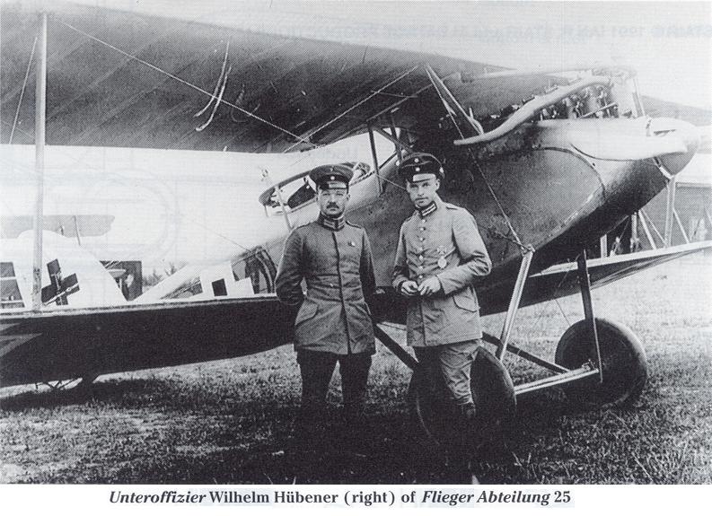
Unteroffizier Wilhelm Hubener (right) of Flieger Abteilung 25
-

J.Herris - Halberstadt Aircraft of WWI. Volume 1: A-types to C.III /Centennial Perspective/ (44)
Ltns. Hubener and von Schaesberg of Flieger Abteilung 25.
Aircrew of a Halberstadt CL.II of an unknown unit in 1918 photographed before their mission. (Peter M. Grosz collection/STDB) -

J.Herris - Halberstadt Aircraft of WWI. Volume 1: A-types to C.III /Centennial Perspective/ (44)
Two views of a Halberstadt CL.II gunner loading pigeons; note the wireless generator. (Peter M. Grosz collection/STDB)
-

J.Herris - Halberstadt Aircraft of WWI. Volume 1: A-types to C.III /Centennial Perspective/ (44)
A crew of Schlasta 26b is ready for their next mission in their Halberstadt CL.II. The wire guard on the upper wing is there to prevent the gunner from damaging the propeller by firing through the propeller arc. (Peter M. Grosz collection/STDB)
-

J.Herris - Halberstadt Aircraft of WWI. Volume 1: A-types to C.III /Centennial Perspective/ (44)
Pilot of a Halberstadt CL.II in 1918.The speckled camouflage was applied at the factory. (Peter M. Grosz collection/STDB)
-

J.Herris - Halberstadt Aircraft of WWI. Volume 1: A-types to C.III /Centennial Perspective/ (44)
Halberstadt CL.II and crew of Schlasta 6 with colorful markings. (Tobias Weber)
-

J.Herris - Halberstadt Aircraft of WWI. Volume 1: A-types to C.III /Centennial Perspective/ (44)
Late production Halberstadt CL.II '7' of Schlasta 27 heads this Schlasta lineup; '7' has girl's names Ria and Melanie.
-

J.Herris - Halberstadt Aircraft of WWI. Volume 1: A-types to C.III /Centennial Perspective/ (44)
The crew of Brunhilde, tactical number 2 of its Schlactstaffel, Schlasta 27b, prepares for another ground-attack mission. The gunner has hand grenades in a rack along the side of the fuselage and signal flares in a belt behind his cockpit. The CL.IV was a modification of the CL.II to improve maneuverability, important to the survival of these unarmored aircraft at the low altitudes at which they attacked Allied ground targets. Power for both types was the 160 hp Mercedes D.III engine also used in the Albatros fighters.
-

J.Herris - Halberstadt Aircraft of WWI. Volume 1: A-types to C.III /Centennial Perspective/ (44)
The postcard made of the above photo. (Peter M. Grosz collection/STDB)
-

Jane's All The World Aircraft 1919 /Jane's/
Gunner-observer on a Halberstadt, equipped for Contour-fighting, with hand-grenades.
-

J.Herris - Halberstadt Aircraft of WWI. Volume 1: A-types to C.III /Centennial Perspective/ (44)
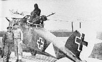
A ground crewman loads grenades on Halberstadt CL.II ‘2' Brunhilde of Schlactstaffel 21. (Peter M. Grosz collection/STDB)
-

J.Herris - Halberstadt Aircraft of WWI. Volume 1: A-types to C.III /Centennial Perspective/ (44)
Gunner of a Halberstadt CL II of Schlachtstaffel 27 taking on trench mortar fragmentation bombs (Wurfgranaten 15) to augment the ten 'potatomasher' stick grenades carried on the external fuselage rack. From the very low altitudes at which these aircraft operated in attacks on enemy troops and trenches, they were ideally equipped with these slightly modified infantry weapons. The bandolier across the fuselage decking contains signal flares for communicating with German troops. A total of 750 machines of the CL category was operational at the end of April 1918.
-

J.Herris - Halberstadt Aircraft of WWI. Volume 1: A-types to C.III /Centennial Perspective/ (44)
A ground crewman and the gunner of a Halberstadt CL.II load Fliegermaus (Wurfgranate 15 fragmentation bombs) to fill the side racks. (Peter M. Grosz collection/STDB)
-

J.Herris - Halberstadt Aircraft of WWI. Volume 1: A-types to C.III /Centennial Perspective/ (44)
The gunner of Halberstadt CLII is handed clustered potato-masher grenades (called Teufelsfaust, a configuration very effective against tanks) in preparation for a ground-attack mission. Fliegermaus (bombs) fill the side racks. (Peter M. Grosz collection/STDB)
-

J.Herris - Halberstadt Aircraft of WWI. Volume 1: A-types to C.III /Centennial Perspective/ (44)
The ground crew of Schlactstaffel 27 prepare grenades and fragmentation bombs before loading them on the unit's Halberstadt CL.II aircraft. The aircraft, in 1918 insignia, have unit insignia and individual names. (Peter M. Grosz collection/STDB)
-

J.Herris - Halberstadt Aircraft of WWI. Volume 1: A-types to C.III /Centennial Perspective/ (44)
A BFW-built Halberstadt CL.II in 1918 national insignia together with an another fighter is 1917 national insignia. The CL.II is unarmed and likely at a training center. (Peter M. Grosz collection/STDB)
-

J.Herris - Halberstadt Aircraft of WWI. Volume 1: A-types to C.III /Centennial Perspective/ (44)
Another view of the BFW-built Halberstadt CL.II shown above. (Peter M. Grosz collection/STDB)
-

J.Herris - Halberstadt Aircraft of WWI. Volume 1: A-types to C.III /Centennial Perspective/ (44)
Halberstadt CL.II with the white/black/white fuselage bands from Schlasta 9, and Hannover aircraft of an unknown unit at the front in 1918. The late historian Heinz Nowarra notes this as aircraft of Schlachtstaffel-gruppe D at Linselles, May 1918. The Schlagru D consisted of Schlastas 9, 12, 16, 24b, and 25b and was commanded by Oblt. Johannes Missfelder. (Peter M. Grosz collection/STDB)
Другие самолёты на фотографии: Hannover (Hawa) CL.II/CL.III/CL.IIIa - Германия - 1917
-

J.Herris - Halberstadt Aircraft of WWI. Volume 1: A-types to C.III /Centennial Perspective/ (44)
An aviator with his Halberstadt CL.II(Bay) in 1918 national insignia. (Peter M. Grosz collection/STDB)
-

J.Herris - Halberstadt Aircraft of WWI. Volume 1: A-types to C.III /Centennial Perspective/ (44)
Crewman with his Halberstadt CL.II with dynamo and 1918 insignia either attached to or photographed on the Flieger Abteilung 44 airfield. (Peter M. Grosz collection/STDB)
-

J.Herris - Halberstadt Aircraft of WWI. Volume 1: A-types to C.III /Centennial Perspective/ (44)
Crew of a Halberstadt CL.II of an unknown unit pose with their aircraft. The aircraft has a propeller-driven generator on the port landing gear, suggesting it was used by an artillery spotting unit. (Tobias Weber)
-

J.Herris - Halberstadt Aircraft of WWI. Volume 1: A-types to C.III /Centennial Perspective/ (44)
Halberstadt CL.II '2' in the background with Hannover CL '4' of an unknown unit.
Другие самолёты на фотографии: Hannover (Hawa) CL.II/CL.III/CL.IIIa - Германия - 1917
-

J.Herris - Halberstadt Aircraft of WWI. Volume 1: A-types to C.III /Centennial Perspective/ (44)
Halberstadt CL.II '2' of an unknown unit, possibly Schlasta 15, with no spinner in 1918. (Peter M. Grosz collection/STDB)
-

J.Herris - Halberstadt Aircraft of WWI. Volume 1: A-types to C.III /Centennial Perspective/ (44)
Unknown crewman poses with his fully-armed Halberstadt CL.II of an unknown unit in 1918. (Peter M. Grosz collection/STDB)
-
A.Imrie - German Naval Air Service /Arms & Armour/
Not only did two-seat high-performance landplanes like this Halberstadt CL II serve in the two Marine Schlachtstaffeln on ground support work with the naval infantry, and on oversea air-fighting duties as required, but a number were also used at night by a special naval unit (Masosta) under Leutnant Majewski against the frequent penetrations of Handley Pages bombing the U-boat installations at Bruges.
-

J.Herris - Halberstadt Aircraft of WWI. Volume 1: A-types to C.III /Centennial Perspective/ (44)
Gunner Uffz. Hilsebein and (very probably) Pilot Uffz. Artur Bartsch from Schlasta 15 pose with their aircraft in March 1918, during the Great Spring Offensive called Operation Michael. About one month later Artur Bartsch was KIA. The Halberstadt had a two color striped spinner and a plywood repair near the upper part of the tail. (Peter M. Grosz collection/STDB)
-

J.Herris - Halberstadt Aircraft of WWI. Volume 1: A-types to C.III /Centennial Perspective/ (44)
Fully armed Halberstadt CL.II '4' of Schlastastaffel 33 with aircrew and ground crew in 1918. The two-color fuselage stripes are the unit marking. Note the excessive white borders to the fuselage cross.
-

J.Herris - Halberstadt Aircraft of WWI. Volume 1: A-types to C.III /Centennial Perspective/ (44)
Fully armed Halberstadt CL.II '6' of Schlastastaffel 33 with aircrew and ground crew in 1918. The two-color fuselage stripes are the unit marking. Note the excessive white borders to the fuselage cross.
-

J.Herris - Halberstadt Aircraft of WWI. Volume 1: A-types to C.III /Centennial Perspective/ (44)
Lineup of Halberstadt CL.II aircraft of Schlastastaffel 33 in 1918.
-

J.Herris - Halberstadt Aircraft of WWI. Volume 1: A-types to C.III /Centennial Perspective/ (44)
A naval aircrew with their Halberstadt CL.II. The observer's gun is fitted with an Oigee telescopic sight. The old style insignia has been repainted by the 1918 style insignia. The serial data aft of the insignia was applied to later production aircraft. (Peter M. Grosz collection/STDB)
-

J.Herris - Halberstadt Aircraft of WWI. Volume 1: A-types to C.III /Centennial Perspective/ (44)
Unarmed Halberstadt CL.II without spinner and late-style insignia. (Peter M. Grosz collection/STDB)
-

J.Herris - Halberstadt Aircraft of WWI. Volume 1: A-types to C.III /Centennial Perspective/ (44)
Late production Halberstadt CL.II '5' of Schlasta 30 with its crew in 1918 insignia and white fin and rudder.
-

J.Herris - Halberstadt Aircraft of WWI. Volume 1: A-types to C.III /Centennial Perspective/ (44)
Crew of a Halberstadt CL.II of Schlasta 21 in black and white unit markings in 1918.
-

J.Herris - Halberstadt Aircraft of WWI. Volume 1: A-types to C.III /Centennial Perspective/ (44)
Crew of a Halberstadt CL.II of Schlasta 21 in black and white unit markings in 1918.
-

J.Herris - Halberstadt Aircraft of WWI. Volume 1: A-types to C.III /Centennial Perspective/ (44)
A Halberstadt-built CL.II with 1918 insignia and fitted with a dynamo. (Peter M. Grosz collection/STDB)
-

J.Herris - Halberstadt Aircraft of WWI. Volume 1: A-types to C.III /Centennial Perspective/ (44)
Halberstadt CLII '2' and crew of an unknown unit with 1918 insignia and a dynamo. (Peter M. Grosz collection/STDB)
-

J.Herris - Halberstadt Aircraft of WWI. Volume 1: A-types to C.III /Centennial Perspective/ (44)
Halberstadt CL.II and crew of an unknown unit in 1918. A dynamo is fitted and radio antenna is seen. (Peter M. Grosz collection/STDB)
-

Сайт - Pilots-and-planes /WWW/
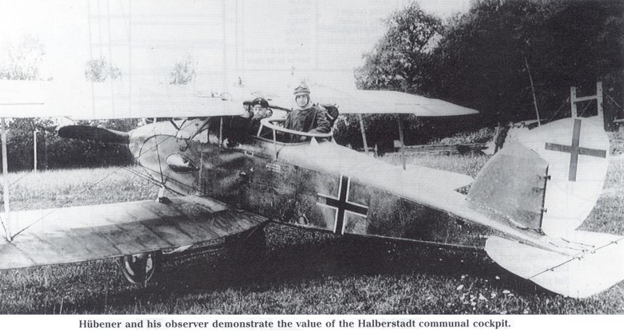
Hubener and his observer demonstrate the value of the Halberstadt communal cockpit.
-

J.Herris - Halberstadt Aircraft of WWI. Volume 1: A-types to C.III /Centennial Perspective/ (44)
Lt. Edmund Brandt and enlisted pilot Scheffler of FA(A) 219 with their Halberstadt CL.II. The observer's gun if fitted with an Oigee telescopic sight. (Peter M. Grosz collection/STDB)
-

J.Herris - Halberstadt Aircraft of WWI. Volume 1: A-types to C.III /Centennial Perspective/ (44)
A Halberstadt CL.II aircrew from FliegerAbteilung (A) 219 prepares for a mission in 1918. Captured Italian Villar-Perosa twin-barrel sub-machine guns have been fitted for the gunner in his cockpit and over the wing. (Peter M. Grosz collection/STDB)
-

J.Herris - Halberstadt Aircraft of WWI. Volume 1: A-types to C.III /Centennial Perspective/ (44)
Crew of a Halberstadt CL.II of Schlasta 14 with a guest. (Reinhard Zankl)
-

J.Herris - Halberstadt Aircraft of WWI. Volume 1: A-types to C.III /Centennial Perspective/ (44)
Uzfw. Huffzky and Vzfw. Gottfried Ehmann of Schlasta 15 in their Halberstadt CLII after return from a combat mission. Ehmann was a two-seater ace credited with 12 victories. There is a simple bomb rack for six fragmentation bombs, here empty after their mission. (Peter M. Grosz collection/STDB)
-

J.Herris - Halberstadt Aircraft of WWI. Volume 1: A-types to C.III /Centennial Perspective/ (44)
Eugen Fath photographed with Halberstadt CL.II halbe Portion.
-

J.Herris - Halberstadt Aircraft of WWI. Volume 1: A-types to C.III /Centennial Perspective/ (44)
Two views of a Halberstadt CL.II 'halbe Portion' (half portion) of an unidentified unit and crew in 1918 insignia. The bulged, teardrop-shaped fairing indicated a dynamo was fitted. The fuselage cross has been over-painted and the rudder cross is non-standard. (Peter M. Grosz collection/STDB)
-

J.Herris - Halberstadt Aircraft of WWI. Volume 1: A-types to C.III /Centennial Perspective/ (44)
Late production Halberstadt CL.II of an unknown unit in 1918 insignia and fitted with a dynamo. (Peter M. Grosz collection/STDB)
-

J.Herris - Halberstadt Aircraft of WWI. Volume 1: A-types to C.III /Centennial Perspective/ (44)
Halberstadt CLII without a dynamo, probably from a Marine Schutzstaffel in 1918. (Peter M. Grosz collection/STDB)
-

J.Herris - Halberstadt Aircraft of WWI. Volume 1: A-types to C.III /Centennial Perspective/ (44)
A pilot with his unarmed Halberstadt CL.II in 1918 insignia. The lack of armament and wood wheels indicate training service. (Peter M. Grosz collection/STDB)
-

J.Herris - Halberstadt Aircraft of WWI. Volume 1: A-types to C.III /Centennial Perspective/ (44)
Unknown crewmen of Schlasta 25b pose with their Halberstadt CL.II.
-

J.Herris - Halberstadt Aircraft of WWI. Volume 1: A-types to C.III /Centennial Perspective/ (44)
The aircrew show their preparation for an unlikely gas attack. This Halberstadt CL.II was fitted with rear-view mirrors for the pilot. (Peter M. Grosz collection/STDB)
-

J.Herris - Halberstadt Aircraft of WWI. Volume 1: A-types to C.III /Centennial Perspective/ (44)
Huffzky and Ehmann of Schlasta 15 during gas exercises in front of their Halberstadt CL.II. The fragmentation bomb rack is fully loaded.
-

J.Herris - Halberstadt Aircraft of WWI. Volume 1: A-types to C.III /Centennial Perspective/ (44)
Crew with their Halberstadt CL.II of an unknown unit in 1917. (Peter M. Grosz collection/STDB)
-

J.Herris - Halberstadt Aircraft of WWI. Volume 1: A-types to C.III /Centennial Perspective/ (44)
Crew of a Halberstadt CL.II of an unknown unit prepared for flight. (Peter M. Grosz collection/STDB)
-

J.Herris - Halberstadt Aircraft of WWI. Volume 1: A-types to C.III /Centennial Perspective/ (44)
The crew of a standard Halberstadt CL.II, Gawron and ?, Schutzstaffel 2, pose with their aircraft. (Peter M. Grosz collection/STDB)
-

J.Herris - Halberstadt Aircraft of WWI. Volume 1: A-types to C.III /Centennial Perspective/ (44)
Vzfw. Steinworth and Vzfw. Gawron of Schlasta 2 with their Halberstadt CL.II.
-

J.Herris - Halberstadt Aircraft of WWI. Volume 1: A-types to C.III /Centennial Perspective/ (44)
A proud Halberstadt CL.II crewman photographed in front of his aircraft. (Peter M. Grosz collection/STDB)
-

J.Herris - Halberstadt Aircraft of WWI. Volume 1: A-types to C.III /Centennial Perspective/ (44)
Unidentified crew of a mid-production Halberstadt CL.II in the snow.
-

J.Herris - Halberstadt Aircraft of WWI. Volume 1: A-types to C.III /Centennial Perspective/ (44)
Halberstadt officials pose with a Halberstadt CL.II without spinner in 1918. Karl Theis is on the right. (Peter M. Grosz collection/STDB)
-

J.Herris - Halberstadt Aircraft of WWI. Volume 1: A-types to C.III /Centennial Perspective/ (44)
Halberstadt CL.II without spinner after capture. (Peter M. Grosz collection/STDB)
-

J.Herris - Halberstadt Aircraft of WWI. Volume 1: A-types to C.III /Centennial Perspective/ (44)
Personnel of Schlasta 26b pose with a Halberstadt CL.II. (Peter M. Grosz collection/STDB)
-

J.Herris - Halberstadt Aircraft of WWI. Volume 1: A-types to C.III /Centennial Perspective/ (44)
Flyers of FA 207 and Schlachtstaffel 15 pose with a Halberstadt CL.II in the background in April 1918. (Peter M. Grosz collection/STDB)
-

J.Herris - Halberstadt Aircraft of WWI. Volume 1: A-types to C.III /Centennial Perspective/ (44)
Halberstadt CL.II at Fliegerdepot Nord with aircrew and ground crew. (Reinhard Zankl)
-

J.Herris - Halberstadt Aircraft of WWI. Volume 1: A-types to C.III /Centennial Perspective/ (44)
Ground crew of an unknown unit pose with a Halberstadt CL.II. This is almost certainly a post armistice photograph during demobilization of the flying units in Bavaria. (Reinhard Zankl)
-

J.Herris - Halberstadt Aircraft of WWI. Volume 1: A-types to C.III /Centennial Perspective/ (44)
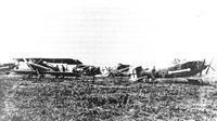
Typical Schlachtstaffel equipped with Halberstadt CL.IIs. The field aerodrome was set up quickly with canvas tents close to the fast-moving front, during Operation Michael in Sprint 1918. (Peter M. Grosz collection/STDB)
-

J.Herris - Halberstadt Aircraft of WWI. Volume 1: A-types to C.III /Centennial Perspective/ (44)
Two aviators with Halberstadt CL.II aircraft in the background. (Peter M. Grosz collection/STDB)
-
J.Herris - Halberstadt Aircraft of WWI. Volume 2: CL.IV-CLS.I & Fighters /Centennial Perspective/ (45)
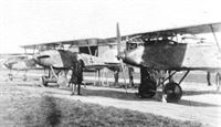
Halberstadt CL.IV '3' and a Halberstadt CL.II of Schlasta 33 and Hannover CL.IIIa aircraft of Schlasta 20. (Peter M. Grosz collection/STDB)
Другие самолёты на фотографии: Halberstadt CL.IV - Германия - 1918Hannover (Hawa) CL.II/CL.III/CL.IIIa - Германия - 1917
-
J.Herris - Halberstadt Aircraft of WWI. Volume 2: CL.IV-CLS.I & Fighters /Centennial Perspective/ (45)
Halberstadt CL.IV second from left from Schlasta 33 and Hannovers in the background of (probably) Schlasta 20 on August 10,1918. Aircraft at left is a Halberstadt CL.II with another behind the CL.IV. (Peter M. Grosz collection/STDB)
Другие самолёты на фотографии: Halberstadt CL.IV - Германия - 1918Hannover (Hawa) CL.II/CL.III/CL.IIIa - Германия - 1917
-
J.Herris - Halberstadt Aircraft of WWI. Volume 1: A-types to C.III /Centennial Perspective/ (44)
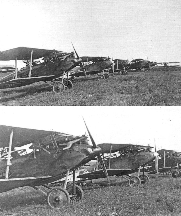
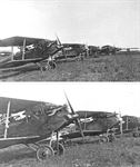
Two views of a Schlachtstaffel 24b lineup with Halberstadt CL.II aircraft in the foreground, a Halberstadt CLIV in the middle, with Hannover CL-types in the background. Documents say that Schlasta machine no. 5 is seen after plywood replacement in the Germania works. Each Halberstadt's early types had trouble with wrinkled plywood, the worst being replaced with new plywood in other factories not necessary Halberstadt. After that process the fuselage was painted in other ways characteristic for this manufacturer's camouflage. (Peter M. Grosz collection/STDB)
Другие самолёты на фотографии: Halberstadt CL.IV - Германия - 1918Hannover (Hawa) CL.II/CL.III/CL.IIIa - Германия - 1917
-

J.Herris - Halberstadt Aircraft of WWI. Volume 1: A-types to C.III /Centennial Perspective/ (44)
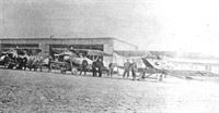
Halberstadt CL.II of Schlasta 23b on left and Hannover aircraft of an unknown Schlasta at right on an airfield of an unknown Schlachtgruppe. (Peter M. Grosz collection/STDB)
Другие самолёты на фотографии: Hannover (Hawa) CL.II/CL.III/CL.IIIa - Германия - 1917
-

J.Herris - Halberstadt Aircraft of WWI. Volume 1: A-types to C.III /Centennial Perspective/ (44)
Halberstadt CL.II aircraft of Schlasta 23b. The dynamos have been removed and the flat covers fitted. Two of the covers have been painted white and one has been named Rosi. The late historian Heinz Nowarra gives this unit as Schlachtstagfel 22 that was part of Schlachtstaffelgruppe D. The white painted dynamo covers were the Stoffel marking; Rosi was the Staffers lead aircraft. (Peter M. Grosz collection/STDB)
-
J.Herris - Halberstadt Aircraft of WWI. Volume 1: A-types to C.III /Centennial Perspective/ (44)
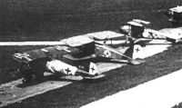
Halberstadt CL.II lined up with Albatros fighters of Jasta 37.
Другие самолёты на фотографии: Albatros D.V/D.Va - Германия - 1917
-
J.Herris - Halberstadt Aircraft of WWI. Volume 1: A-types to C.III /Centennial Perspective/ (44)
Halberstadt CL.II and Albatros fighters of Seefrontstaffel II at Neumuenster. The Halberstadt was painted in Jagdstaffel markings with yellow nose and rudder.
Другие самолёты на фотографии: Albatros D.V/D.Va - Германия - 1917
-

J.Herris - Development of German Warplanes in WWI /Centennial Perspective/ (1)
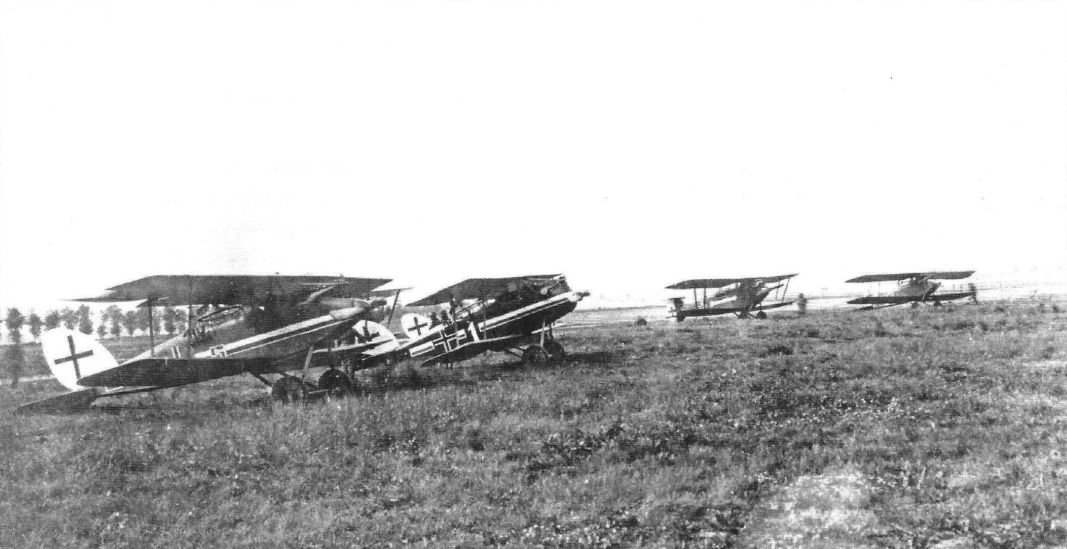
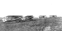
Halberstadt lineup of Schlachtstaffel 21. The commanding officer's CL.IV is third from right and is the aircraft depicted in the colors of the restored CL.IV in the National Museum of the USAF. The other CL.II aircraft have their black and white colors reversed; their black stripes are wider than their white stripes. The distinctive markings of the leader's aircraft helped the others maintain formation on it during combat.
Другие самолёты на фотографии: Halberstadt CL.IV - Германия - 1918
-

J.Herris - Halberstadt Aircraft of WWI. Volume 1: A-types to C.III /Centennial Perspective/ (44)
Schlasta circus on its aerodrome with tents. Halberstadt CL.II of an unknown unit flys over its airfield in 1918. (Peter M. Grosz collection/STDB)
-

J.Herris - Halberstadt Aircraft of WWI. Volume 1: A-types to C.III /Centennial Perspective/ (44)
Halberstadt CL.II of an unknown Schlasta flies low over its airfield. (Peter M. Grosz collection/STDB)
-

J.Herris - Halberstadt Aircraft of WWI. Volume 1: A-types to C.III /Centennial Perspective/ (44)
Halberstadt CL.II of perhaps Schlasta 15 flying low over troops. (Peter M. Grosz collection/STDB)
-

J.Herris - Halberstadt Aircraft of WWI. Volume 1: A-types to C.III /Centennial Perspective/ (44)
Production Halberstadt CL.II of an unknown unit makes a low pass. (Peter M. Grosz collection/STDB)
-

J.Herris - Halberstadt Aircraft of WWI. Volume 1: A-types to C.III /Centennial Perspective/ (44)
Lt. Pysall from FliegerAbteilung(A) 212 waves to the crew of one of the two-seaters he is escorting from his Halberstadt CL.II of Schutzstaffel 2 in 1917 insignia.The camouflage fabric covering the wings and tail shows clearly. (Peter M. Grosz collection/STDB)
-

J.Herris - Halberstadt Aircraft of WWI. Volume 1: A-types to C.III /Centennial Perspective/ (44)
Halberstadt CL.II of an unknown unit in flight in 1917. (Peter M. Grosz collection/STDB)
-

J.Herris - Halberstadt Aircraft of WWI. Volume 1: A-types to C.III /Centennial Perspective/ (44)
Chief pilot W. Voigt demonstrates the maneuverability of the Halberstadt CL.II in CL.II 5759/17 on November 28, 1917. This was done at Fliegerhorst Frankfurt n/Oder at Bomben-Versuch-Abteilung. After those tests some Halberstadts were sent to fighter squadrons for evaluation as two-seat fighters. (Peter M. Grosz collection/STDB)
-

J.Herris - Halberstadt Aircraft of WWI. Volume 1: A-types to C.III /Centennial Perspective/ (44)
A BFW-built Halberstadt CL.II in flight. (Peter M. Grosz collection/STDB)
-
J.Herris - Development of German Warplanes in WWI /Centennial Perspective/ (1)
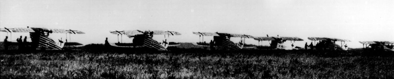
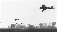
The six Halberstadt CL.II aircraft of a Schlactstaffeln on their low-level run to the target in 1918. By this time the CL-type aircraft had grown beyond their original escort duties and the Schlastas had well-developed tactics for ground-attack.
A Schlactstaffel of Halberstadt CL.II ground-attack fighters races low over the countryside en route to attack targets in Allied lines. Special tactics enhanced their effectiveness and limited their casualties on these hazardous missions. In 1918 the Schlastas were the offensive striking arm of the German air service. They were also tough opponents for Allied fighters due to their excellent maneuverability and rear gunner. -

J.Herris - Halberstadt Aircraft of WWI. Volume 1: A-types to C.III /Centennial Perspective/ (44)
Halberstadt CLII of an unknown unit fitted with a dynamo coming in to land in 1918. (Peter M. Grosz collection/STDB)
-

J.Herris - Halberstadt Aircraft of WWI. Volume 1: A-types to C.III /Centennial Perspective/ (44)
Captured Halberstadt CL.II 1755/17 (???) repainted in French markings. The crew, Pilot Sgt. Kuchenbacher and observer Sgt. Otto Becker, were from Schlasta 15 and were captured October 13, 1918. A P.u.W. bomb rack was fitted under the fuselage. (Peter M. Grosz collection/STDB)
-

M.Kabatek, Fr.R.Kulczynski - German Aircraft in Polish Service. Volume 1 /Aeronaut/
During 1990-1993 Halberstadt Cl.II 15459/17 underwent extensive restoration. The original camouflage was recreated, relics of which were protected under a coat of contemporary washable paints. (Piotr Pokulniewicz)
-

J.Herris - Halberstadt Aircraft of WWI. Volume 1: A-types to C.III /Centennial Perspective/ (44)
Views of Gen Lt. Ernst von Hoeppner's restored personal transport plane, Halberstadt CL.II 15459/17, as it sits in Krakow's Muzeum Lotnictwa Polskiego. (Adam Wait)
-

J.Herris - Halberstadt Aircraft of WWI. Volume 1: A-types to C.III /Centennial Perspective/ (44)
Views of Gen Lt. Ernst von Hoeppner's restored personal transport plane, Halberstadt CL.II 15459/17, as it sits in Krakow's Muzeum Lotnictwa Polskiego. (Adam Wait)
-

J.Herris - Halberstadt Aircraft of WWI. Volume 1: A-types to C.III /Centennial Perspective/ (44)
Hoeppner's restored personal transport plane, Halberstadt CLII 15459/17, as it sits in Krakow's Muzeum Lotnictwa Polskiego. (Robert Reichert)
-

-

J.Herris - Halberstadt Aircraft of WWI. Volume 1: A-types to C.III /Centennial Perspective/ (44)
Closeup of Halberstadt CL.II 15459/17 fuselage after restoration. (Adam Wait)
-

J.Herris - Halberstadt Aircraft of WWI. Volume 1: A-types to C.III /Centennial Perspective/ (44)
Reconstructed original side inscription. (Adam Wait)
-

J.Herris - Halberstadt Aircraft of WWI. Volume 1: A-types to C.III /Centennial Perspective/ (44)
ZAK acceptance stamp with HFW work number. (Adam Wait)
-

J.Herris - Halberstadt Aircraft of WWI. Volume 1: A-types to C.III /Centennial Perspective/ (44)
Views of Gen Lt. Ernst von Hoeppner's personal transport plane, Halberstadt CL.II 15459/17, before it was restored. Here it rests in Krakow's Muzeum Lotnictwa Polskiego. German inscriptions painted on the outside of fuselage were applied during "restoration"and are not original. (Peter M. Grosz collection/STDB)
-

J.Herris - Halberstadt Aircraft of WWI. Volume 1: A-types to C.III /Centennial Perspective/ (44)
Closeup of pilot's step. (Adam Wait)
-

J.Herris - Halberstadt Aircraft of WWI. Volume 1: A-types to C.III /Centennial Perspective/ (44)
Rudder construction. (Adam Wait)
-

M.Kabatek, Fr.R.Kulczynski - German Aircraft in Polish Service. Volume 1 /Aeronaut/
On Halberstadt Cl.II 15459/17 (w/n 1046), used as the personal aircraft of Generalleutnant Ernst von Hoeppner during WWI, is one of the exhibits of the Muzeum Lotnictwa Polskiego (Polish Aviation Museum) in Cracow. In the interwar period, the aircraft was part of the Deutsche Luftfahrtsammlung collection in Berlin. In mid-1943, it was evacuated, together with other exhibits, to German-occupied Poland, where it survived until the end of the war. In 1963, incomplete and damaged at the time, it was handed over to the Muzeum Lotnictwa Polskiego in Cracow. (Muzeum Lotnictwa Polskiego w Krakowie; Stanislaw Wielgus)
-

J.Herris - Halberstadt Aircraft of WWI. Volume 1: A-types to C.III /Centennial Perspective/ (44)
Views of Gen Lt. Ernst von Hoeppner's personal transport plane, Halberstadt CL.II 15459/17, before it was restored. Here it rests in Krakow's Muzeum Lotnictwa Polskiego. (Peter M. Grosz collection/STDB)
-

J.Herris - Halberstadt Aircraft of WWI. Volume 1: A-types to C.III /Centennial Perspective/ (44)
Views of Gen Lt. Ernst von Hoeppner's personal transport plane, Halberstadt CL.II 15459/17, before it was restored. Here it rests in Krakow's Muzeum Lotnictwa Polskiego. German inscriptions painted on the outside of fuselage were applied during "restoration" and are not original. (Peter M. Grosz collection/STDB)
-

M.Kabatek, Fr.R.Kulczynski - German Aircraft in Polish Service. Volume 1 /Aeronaut/
Halberstadt (Bay) Cl.II 781/18 at Velyka Berezovytsia, August 1919. Ppor.pil. Jozef Mahczak, commanding the III Esk. Wlkp., is standing second right. He was an experienced pilot, who had served with the AFA 214, Jasta 33, Jasta 5, Kest 4b and Kest 4a during WWI. (Biblioteka Uniwersytecka w Poznaniu)
-

M.Kabatek, Fr.R.Kulczynski - German Aircraft in Polish Service. Volume 1 /Aeronaut/
Personnel of the III Esk. Wlkp. by Halberstadt Cl.II (Bay) 781/18. Polish serial 201/18 can be seen on the fuselage. The presence of the Parabellum LMG 14 machine gun on the observer's ring suggests that the photos may have been taken before the combat sortie on 23 August 1919. (Biblioteka Uniwersytecka w Poznaniu)
-

A.Olejko - War Wings Over Galicia 1918-1919 /Aeronaut/
Flying mosaic... In the winter of 1918/1919, a large number of types of aircraft were used in Polish aviation, which from the German, Austro-Hungarian and Russian air forces went to the Polish squadrons fighting in the Polish-Ukrainian war. In the photograph is Halberstadt CL.II.
-

M.Kabatek, Fr.R.Kulczynski - German Aircraft in Polish Service. Volume 1 /Aeronaut/
Halberstadt CL.II(BFW) ex 782/18 powered by a Mercedes D.III engine in postwar Polish service. 202/18 is a Polish number that was not of German origin. (Peter M. Grosz collection/STDB)
Two photos of Halberstadt Cl.II (Bay) 782/18 taken in Cracow in March 1919. At that time, the machine gun ring was not fitted on the aircraft. Polish serial 202/18 is on the fuselage. Overpainted Balkenkreuze are visible beneath the national insignia. (Fr. Robert Kulczyhski SDB; Muzeum Lotnictwa Polskiego w Krakowie) -

M.Kabatek, Fr.R.Kulczynski - German Aircraft in Polish Service. Volume 1 /Aeronaut/
Halberstadt Cl.II (Bay) 782/18 was among the aircraft displayed on 9 March 1919, to Allied officers visiting Lawica. It is seen here as the second down the line. (The Polish Institute and Sikorski Museum)
-

M.Kabatek, Fr.R.Kulczynski - German Aircraft in Polish Service. Volume 1 /Aeronaut/
Halberstadt CL.II (Bay) 753/18 during maintenance inside a hangar at Lawica, summer 1919. Training aircraft used at the Stacja Lotnicza Lawica were given Polish serials, applied on both sides of the fuselage (here: 208/18). (Muzeum Lotnictwa Polskiego w Krakowie)
-

M.Kabatek, Fr.R.Kulczynski - German Aircraft in Polish Service. Volume 1 /Aeronaut/
Initially, Halberstadt CL.II (Bay) 753/18 was used for training at the Szkola Pilotow at Lawica. (Fr. Robert Kulczyhski SDB)
-

M.Kabatek, Fr.R.Kulczynski - German Aircraft in Polish Service. Volume 1 /Aeronaut/
A close-up of the forward fuselage of Halberstadt Cl.ll (Bay) 753/18 shows numerous traces of repairs of the plywood skin. (Fr. Robert Kulczynski SDB)
-

J.Herris - Halberstadt Aircraft of WWI. Volume 1: A-types to C.III /Centennial Perspective/ (44)
BFW production Halberstadt CL.II (Bay) ex 2869/18 in Polish service in Poznan in 1919. Polish gave the aircraft number 223/18 after repair when the gun ring removed. (Peter M. Grosz collection/STDB)
-

M.Kabatek, Fr.R.Kulczynski - German Aircraft in Polish Service. Volume 1 /Aeronaut/
The photo, taken in 1921, shows details of the aircraft: numerous traces of repainting the skin, the number 55, new style Polish insignia (with outlines), a rectangular field with the Polish serial, and the inscription 'Stacja lotnicza Poznan. Lawica Tel. 4326’ ('Poznan air station, Lawica Tel. 4326'). (Muzeum Lotnictwa Polskiego w Krakowie)
-

J.Herris - Halberstadt Aircraft of WWI. Volume 1: A-types to C.III /Centennial Perspective/ (44)
Halberstadt CL.II (BFW) 2873/18 powered by a 180 hp Argus As.III engine. The aircraft was photographed in 1919 on the Gora airfield in Polish service. (Peter M. Grosz collection/STDB)
-

M.Kabatek, Fr.R.Kulczynski - German Aircraft in Polish Service. Volume 1 /Aeronaut/
Pplk pil. Marek Krzyczkowski, Commanding the III Esk. Wlkp., and st. szer. obs. Jozef Klicze in the cockpit of Halberstadt C.IIa (Bay) 2875/18; Gora, June 1919. The weight table: Leergewicht (empty weight) 767Kg. Nutzlast (useful load) 360 Kg. Zulassiges Gesamtgewicht (all-up weight) 1127 Kg. and the inscription: Halb. C.L.II/A (Bay.) 2875/18 are clearly visible on the fuselage. The aircraft has a fixed forward firing LMG 08/15 machine gun and a Parabellum LMG 14 machine gun mounted on the observer's ring. (Dawid Nawrocki)
-

M.Kabatek, Fr.R.Kulczynski - German Aircraft in Polish Service. Volume 1 /Aeronaut/
Halberstadt Cl.II 5760/17 photographed in October 1919 at Babruysk. Plut. Wladyslaw Dziwak is standing at far left. (Wielkopolskie Muzeum Wojskowe - Muzeum Narodowe w Poznaniu)
-

M.Kabatek, Fr.R.Kulczynski - German Aircraft in Polish Service. Volume 1 /Aeronaut/
During 1918-1921, the Polish air service used aircraft of German, French, British, Italian, and Austro-Hungarian production at the same time. Here: Halberstadt Cl.II (Bay) 753/18 and Breguet XIV A2s of the 10. EW. Kozenki, April 1920. (Muzeum Lotnictwa Polskiego w Krakowie)
Другие самолёты на фотографии: Breguet Br.14 - Франция - 1917
-

M.Kabatek, Fr.R.Kulczynski - German Aircraft in Polish Service. Volume 1 /Aeronaut/
Aircraft and pilots of the WSP at Lawica, early 1921. Halberstadt Cl.IIa (Bay) 2869/18 is fourth from the right. (Wielkopolskie Muzeum Wojskowe - Muzeum Narodowe w Poznaniu)
-

M.Kabatek, Fr.R.Kulczynski - German Aircraft in Polish Service. Volume 1 /Aeronaut/
Halberstadt Cl.II (203/18) did not yet have the Polish serial applied during the display for Allied officers visiting Lawica on 9 March 1919, although a rectangular field was already painted on the fuselage. (The Polish Institute and Sikorski Museum)
-

M.Kabatek, Fr.R.Kulczynski - German Aircraft in Polish Service. Volume 1 /Aeronaut/
Halberstadt Cl.II (Bay) 2821/18 was one of the aircraft on display for the Allied officers visiting Lawica on 9 March 1919. At the time of the show, it did not have a Polish serial, although a rectangular field had already been painted on the fuselage. (The Polish Institute and Sikorski Museum)
-

M.Kabatek, Fr.R.Kulczynski - German Aircraft in Polish Service. Volume 1 /Aeronaut/
Halberstadt Cl.II (Bay) 782/18 was named Zochna (a form of Sophie, a girl's name, in Polish) during its service with the II Esk. Wlkp. The photo was probably taken in October 1919 at Babruysk. (Fr. Robert Kulczyhski SDB)
-

M.Kabatek, Fr.R.Kulczynski - German Aircraft in Polish Service. Volume 1 /Aeronaut/
Aircraft of the III Esk. Wlkp.: LVG C.V (211/17) and Halberstadt Cl.II (Bay) 781/18 behind it. Location: Gora, June 1919. (Biblioteka Uniwersytecka w Poznaniu)
Другие самолёты на фотографии: LVG C.V - Германия - 1917
-

M.Kabatek, Fr.R.Kulczynski - German Aircraft in Polish Service. Volume 1 /Aeronaut/
Ppor. obs. Lucjan Kulikowski from the III Esk. Wlkp. by the propeller of Halberstadt Cl.II (203/18). Similar to other Polish Halberstadt Cl.IIs, the aircraft had the spinner removed. (Dawid Nawrocki)
-

M.Kabatek, Fr.R.Kulczynski - German Aircraft in Polish Service. Volume 1 /Aeronaut/
Personnel of the III Esk. Wlkp. by Halberstadt (Bay) Cl.II 781/18. (Biblioteka Uniwersytecka w Poznaniu)
-

A.Olejko - War Wings Over Galicia 1918-1919 /Aeronaut/
"Greater Poland wings" 1919/1920... During the Polish-Ukrainian and Polish-Bolshevik war, the most modern, captured German flying equipment went to the eastern theater of the war along with Greater Poland squadrons. Here is a Halberstadt CL.II. (W. Sankowski's collection)
-

M.Kabatek, Fr.R.Kulczynski - German Aircraft in Polish Service. Volume 1 /Aeronaut/
Halberstadt Cl.IIa (Bay) 2875/18; Gora, June 1919. Pplk pil. Marek Krzyczkowski is seated on the wing, st. szer. obs. Jozef Klicze is standing first right. Thanks to lighting conditions in which the photograph was taken, elements of the wing structure are visible beneath the fabric covering. (Dawid Nawrocki)
-

M.Kabatek, Fr.R.Kulczynski - German Aircraft in Polish Service. Volume 1 /Aeronaut/
Sierz. pil. Antoni Bartkowiak and ppor. pil. Jozef Manczak flew Halberstadt Cl.II (Bay) 782/18 from Lawica to Cracow on 13 March 1919. This photo was probably taken shortly after landing. (Biblioteka Uniwersytecka w Poznaniu)
-

M.Kabatek, Fr.R.Kulczynski - German Aircraft in Polish Service. Volume 1 /Aeronaut/
Halberstadt Cl.II (Bay) 782/18 surrounded by a crowd of onlookers after landing in a field, summer 1919. (Fr. Robert Kulczynski SDB)
-

M.Kabatek, Fr.R.Kulczynski - German Aircraft in Polish Service. Volume 1 /Aeronaut/
The overhauled Halberstadt Cl.IIa (Bay) 2869/18 was delivered to the Szkola Pilotow at Lawica on 11 September 1919. The photo was probably taken before take-off for the acceptance flight. (Wojciech Sankowski)
-

M.Kabatek, Fr.R.Kulczynski - German Aircraft in Polish Service. Volume 1 /Aeronaut/
Halberstadt Cl.IIa (Bay) 2869/18, in the middle of the photo, during an overhaul in the summer of 1919 at the workshops of the Stacja Lotnicza Lawica. Gotha G.IV (SSW) 213/17 bomber is in the background. (Wojciech Sankowski)
Другие самолёты на фотографии: Gotha G.IV - Германия - 1916
-

J.Herris - Halberstadt Aircraft of WWI. Volume 1: A-types to C.III /Centennial Perspective/ (44)
Late production Halberstadt CL.II fitted with captured Italian Villar-Perosa twin-barrel machine guns for the observer and on the top wing. The aircraft is also fitted with a 4-bladed propeller. (Above photo Peter M. Grosz collection/STDB)
-

J.Herris - Halberstadt Aircraft of WWI. Volume 1: A-types to C.III /Centennial Perspective/ (44)
Halberstadt CL.IIa 2873/18 was powered by a 180 hp Argus As.III and evaluated with two fixed forward-firing guns for the pilot, but the extra weight affected performance. As far as is known, this armament was not used in service but late production aircraft had the potential to mount two synchronized guns. The aircraft was photographed in 1919 on the Gora airfield in Polish Service. (Peter M. Grosz collection/STDB)
-

J.Herris - Halberstadt Aircraft of WWI. Volume 1: A-types to C.III /Centennial Perspective/ (44)
Closeup of a Halberstadt CL.II with fixed pilot's gun on the left side. (Peter M. Grosz collection/STDB)
-

J.Herris - Halberstadt Aircraft of WWI. Volume 1: A-types to C.III /Centennial Perspective/ (44)
Closeup of the Mercedes engine installation in a Halberstadt CL.II. (Peter M. Grosz collection/STDB)
-

J.Herris - Halberstadt Aircraft of WWI. Volume 1: A-types to C.III /Centennial Perspective/ (44)
Halberstadt CL.II experimentally fitted with a supercharger for high altitude testing. The Daimler-built Roots-type supercharger for the Mercedes D.IIIa engine was mounted under the fuselage of a Halberstadt CL.II for test. This was chain driven with the chain going round a sprocket on the rear of the propeller hub. The installation was clearly experimental; much further development was needed before superchargers were production ready. (Peter M. Grosz collection/STDB)
-

J.Herris - Halberstadt Aircraft of WWI. Volume 1: A-types to C.III /Centennial Perspective/ (44)
Halberstadt CL.II at the factory experimentally fitted with an LVG machine gun ring. There is no record of service use of this gun ring on the Halberstadt. (Peter M. Grosz collection/STDB)
-
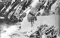
J.Herris - Halberstadt Aircraft of WWI. Volume 1: A-types to C.III /Centennial Perspective/ (44)
BFW production Halberstadt CL.IIa(Bay) with Fliegerersatz Abteilung 8 at Graudenz school badge and other German aircraft collected for destruction postwar. (Peter M. Grosz collection/STDB)
Другие самолёты на фотографии: Albatros C.III - Германия - 1916
-

J.Herris - Halberstadt Aircraft of WWI. Volume 1: A-types to C.III /Centennial Perspective/ (44)
Remains of a captured Halberstadt CL.II. (Peter M. Grosz collection/STDB)
-

J.Herris - Halberstadt Aircraft of WWI. Volume 1: A-types to C.III /Centennial Perspective/ (44)
Damaged Halberstadt CL.II, probably Schlachtstaffel 14, being transported. Note the rear fuselage band. (Reinhard Zankl)
-

J.Herris - Halberstadt Aircraft of WWI. Volume 1: A-types to C.III /Centennial Perspective/ (44)
Halberstadt CL.II of an unknown Schlasta on its nose.
-

J.Herris - Halberstadt Aircraft of WWI. Volume 1: A-types to C.III /Centennial Perspective/ (44)
Halberstadt Cl.II 14307/17 (w/n 778) showing traces of the old Patee cross under the new Balkenkreuz promulgated in March 1918.
-

J.Herris - Halberstadt Aircraft of WWI. Volume 1: A-types to C.III /Centennial Perspective/ (44)
Halberstadt CL.II 15433/17 crashed in the Netherlands in 1918. (Peter M. Grosz collection/STDB)
-

J.Herris - Halberstadt Aircraft of WWI. Volume 1: A-types to C.III /Centennial Perspective/ (44)
Early production Halberstadt CL.II '3' of Schlasta 26b after a rough landing near Lampire on March 24, 1918.
-

J.Herris - Halberstadt Aircraft of WWI. Volume 1: A-types to C.III /Centennial Perspective/ (44)
Halberstadt CL.II '5' of Schusta 23b was crashed by Uffz.Thanfelder. (Peter M. Grosz collection/STDB)
-

J.Herris - Halberstadt Aircraft of WWI. Volume 1: A-types to C.III /Centennial Perspective/ (44)
Early production Halberstadt CL.II '3' of Schlasta 26b after a rough landing near Lampire on March 24, 1918.
-

J.Herris - Halberstadt Aircraft of WWI. Volume 1: A-types to C.III /Centennial Perspective/ (44)
The pilot of this Halberstadt CL.II of an unknown unit in 1918 completely missed the runway. (Peter M. Grosz collection/STDB)
-

J.Herris - Halberstadt Aircraft of WWI. Volume 1: A-types to C.III /Centennial Perspective/ (44)
Downed Halberstadt CL.II with cockade patches over bullet holes. (Reinhard Kastner)
-

J.Herris - Halberstadt Aircraft of WWI. Volume 1: A-types to C.III /Centennial Perspective/ (44)
Halberstadt CL.II was the hack aircraft of Jasta 23b with unit markings; it was crashed by Lt. Otto Hohmuth. The Halberstadts sent to Jastas often had flare pistols mounted in the gunner's cockpit; the barrel is seen here near the gun ring strut.
-

-

J.Herris - Halberstadt Aircraft of WWI. Volume 1: A-types to C.III /Centennial Perspective/ (44)
Halberstadt CL.II of Schlasta 26 downed by Spa 163 on June 23, 1918 is surrounded by French troops. It is one of the few pictures showing two oblique yellow stripes on the upper wing, painted on one production batch, for the gunner showing the area not to fire the gun to avoid hitting the propeller.
-

R.Bennett - Last Gathering of Eagles 1918-1920 /Aeronaut/
Wrecked Halberstadt CL.II of FA 406/Artillerie-Fliegerstaffel 127 at Meseritz. This is likely the machine in which Fritz Kalbreier lost his life 1 July 1919. (Author's collection)
-

J.Herris - Halberstadt Aircraft of WWI. Volume 1: A-types to C.III /Centennial Perspective/ (44)
Soldiers and ground crew by a downed Halberstadt CL.II. (Reinhard Zankl)
-

J.Herris - Halberstadt Aircraft of WWI. Volume 1: A-types to C.III /Centennial Perspective/ (44)
Halberstadt CL.II with altered insignia after a bad landing.
-

J.Herris - Halberstadt Aircraft of WWI. Volume 1: A-types to C.III /Centennial Perspective/ (44)
Halberstadt CL.II down in the barbed wire.
-

M.Kabatek, Fr.R.Kulczynski - German Aircraft in Polish Service. Volume 1 /Aeronaut/
Halberstadt Cl.IIa (Bay) 2869/18 was damaged in an accident between April and July 1920. At the time, it was used as a trainer at the WSP at Lawica. (Muzeum Lotnictwa Polskiego w Krakowie)
-

A.Olejko - War Wings Over Galicia 1918-1919 /Aeronaut/
The wreckage of 1920... During the flights, German service-controlled plane crashed by Lieutenant Jozef Szyfter - commander of the 4th Reconnaissance Squadron - at Baranowicze October 14, 1920 a Halberstadt CL.II. (collections of W. Sankowski and A. Sikorski)
-

M.Kabatek, Fr.R.Kulczynski - German Aircraft in Polish Service. Volume 1 /Aeronaut/
Wreck of Halberstadt Cl.II (Bay) 750/18 that crashed in early 1919 at Lawica. The shape of an overpainted Balkenkreuz is visible beneath the Polish national insignia.This coincidental and undesirable effect could be seen on many German aircraft used in Poland. (The Polish Institute and Sikorski Museum)
-

-

M.Kabatek, Fr.R.Kulczynski - German Aircraft in Polish Service. Volume 1 /Aeronaut/
Wreck of Halberstadt Cl.II (203/18) being loaded onto a truck. (Centrum Kultury w Lecznej)
-

M.Kabatek, Fr.R.Kulczynski - German Aircraft in Polish Service. Volume 1 /Aeronaut/
Halberstadt (Bay) Cl.II 781/18 was slightly damaged during landing at Babruysk in early December 1919. (Muzeum Lotnictwa Polskiego w Krakowie)
-

M.Kabatek, Fr.R.Kulczynski - German Aircraft in Polish Service. Volume 1 /Aeronaut/
In June 1919, Halberstadt C.IIa (Bay) 2875/18 was damaged in an accident. The photo shows details of the lower fuselage that are not usually visible. (Dawid Nawrocki)
-

-

-

Журнал - Flight за 1918 г.
Perspective drawing of the body of the Halberstadt two-seater biplane, 160 h.p. Mercedes engine. Inset is a sketch of the tail planes.
-

Журнал - Flight за 1918 г.
Some constructional details of the Halberstadt fighter. (Figs. 1. to 17.)
-

Журнал - Flight за 1918 г.
More constructional details of the Halberstadt fighter. (Figs. 18 to 31.)
-

-

-

J.Herris - Halberstadt Aircraft of WWI. Volume 1: A-types to C.III /Centennial Perspective/ (44)
Halberstadt CL.II '3' Martha of Schlasta 21
-

J.Herris - Halberstadt Aircraft of WWI. Volume 1: A-types to C.III /Centennial Perspective/ (44)
Halberstadt CL.II '4' of Schlasta 23
-

J.Herris - Halberstadt Aircraft of WWI. Volume 1: A-types to C.III /Centennial Perspective/ (44)
Halberstadt CL.II '4' of Schlasta 26
-

J.Herris - Halberstadt Aircraft of WWI. Volume 1: A-types to C.III /Centennial Perspective/ (44)
Halberstadt CL.II '6' of Schlasta 26
-

J.Herris - Halberstadt Aircraft of WWI. Volume 1: A-types to C.III /Centennial Perspective/ (44)
Halberstadt CL.II '2' Brunhilde of Schlasta 27b
-

J.Herris - Halberstadt Aircraft of WWI. Volume 1: A-types to C.III /Centennial Perspective/ (44)
Halberstadt CL.II Early Factory Colors
-

J.Herris - Halberstadt Aircraft of WWI. Volume 1: A-types to C.III /Centennial Perspective/ (44)
Halberstadt CL.II Mid Factory Colors
-

J.Herris - Halberstadt Aircraft of WWI. Volume 1: A-types to C.III /Centennial Perspective/ (44)
Halberstadt CL.II 4th Production Batch Factory Colors
-

J.Herris - Halberstadt Aircraft of WWI. Volume 1: A-types to C.III /Centennial Perspective/ (44)
Halberstadt CL.II 1st BFW Production Batch Factory Colors
-

J.Herris - Halberstadt Aircraft of WWI. Volume 1: A-types to C.III /Centennial Perspective/ (44)
Halberstadt CL.II 2nd BFW Production Batch Factory Colors
-

M.Kabatek, Fr.R.Kulczynski - German Aircraft in Polish Service. Volume 1 /Aeronaut/
Halberstadt Cl.II (Bay) 781/18 (Polish serial 201/18) of III Eskadra Wielkopolska, flown by ppor. pil. Jozef Manczak and kpr. obs. Jozef Klicze, Velyka Berezovytsia, August 1919
-

M.Kabatek, Fr.R.Kulczynski - German Aircraft in Polish Service. Volume 1 /Aeronaut/
Halberstadt Cl.IIa (Bay) 2875/18 of III Eskadra Wielkopolska, flown by pplk pil. Marek Krzyczkowski and st. szer. obs. Jozef Klicze, Gora, June 1919
-

-

W.Green, G.Swanborough - The Complete Book of Fighters
The CL II in standard configuration.
-

-

-

-

-

-

-

В.Кондратьев Самолеты первой мировой войны
ХАЛЬБЕРШТАДТ CL-II/CL-IIa / HALBERSTADT CL-II/CL-IIa
В начале 1917 года немецкое военное командование разработало комплекс требований для легкого двухместного многоцелевого биплана - новой категории боевых машин, обозначенной индексом "CL".
Эти самолеты должны были оснащаться моторами в 160-180 л.с. и быть достаточно скоростными, маневренными и хорошо вооруженными, чтобы действовать без истребительного эскорта, а при необходимости они и сами могли выступать в роли истребителей.
Первой серийной машиной нового класса стало изделие фирмы "Хальберштадтер Флюгцойгверк" - "Хальберштадт" CL-II - двухместный самолет с размерами одноместного. Опытный экземпляр CL-II поднялся в воздух 7 мая 1917 г.
Этот миниатюрный цельнодеревянный биплан оказался весьма успешным в роли штурмовика и легкого бомбардировщика, особенно, действуя большими группами. Впервые такие массированные атаки с воздуха немцы предприняли в ноябре 1917-го в битве у Камбрэ. В дальнейшем количество "Хальберштадтов" во фронтовых частях постоянно увеличивалось.
Кроме CL-II, выпускался CL-IIa с двигателем повышенной мощности.
К началу августа в немецких "шлахтштаффелях" (штурмовых авиаэскадрильях) на западном фронте числилось 175 "Хальберштадтов" CL-IIa и 136 - CL-IV.
ДВИГАТЕЛЬ
"Мерседес"D.III, 160 л.с. (CL-II) или BMW, 185 л.с. (CL-IIa)
ВООРУЖЕНИЕ
1-2 синхронных "Шпандау" и 1 турельный "Парабеллум", до 50 кг бомб.
ЛЕТНО-ТЕХНИЧЕСКИЕ ХАРАКТЕРИСТИКИ
("Хальберштадт" CL-II)
Размах, м 10,8
Длина, м 7,3
Площадь крыла, кв.м 27,5
Сухой вес, кг 796
Взлетный вес, кг 1160
Скорость максимальная, км/ч 165
Время набора высоты, м/мин 1000/5
Потолок, м 5000
Описание: