P.Lewis The British Fighter since 1912 (Putnam)
Two further single-seat fighters were planned under the R.A.F. Type 1 conditions. These were the Armstrong Whitworth Ara and the Nieuport Nighthawk but neither machine was ready before the beginning of 1919.
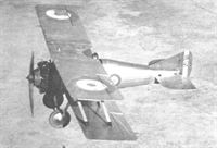
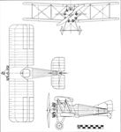
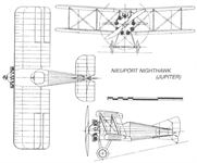
In the design, H. P. Folland succeeded in raising the standard of his art as a single-seat fighter designer to a new level in laying out a two-bay biplane which displayed excellent proportions and looked every inch a fighter. In flight, the Nighthawk’s behaviour was in every way compatible with the promise inherent in its appearance. Handling characteristics and performance figures were admirable, including a top speed of 151 m.p.h. at ground level and a service ceiling of 24,500 ft. The Nighthawk was given what had become the standard armament of twin fixed Vickers guns. Large-scale production of the machine was ordered even though it was powered by the Dragonfly radial but the unfortunate vicissitudes which attended the engine curtailed any chance of widespread service for it.
<...>
A decision was made during 1920 which was to have in the future a momentous effect, unforeseen at the time, on the subsequent development of the British single-seat fighter. This was the agreement among the directors of the Gloucestershire Aircraft Co. of Cheltenham to continue in business as aircraft manufacturers despite the lack of potential orders. The Company’s experience of aeroplane manufacture originated during the War when H. H. Martyn of Sunningend undertook at first sub-contract component work, finally progressing to producing complete aeroplanes of de Havilland and Bristol design. The firm was noted particularly for the outstanding workmanship put into its aircraft and set about continuing its aspirations by acquiring the designs of the Nieuport and General Aircraft Company when that firm closed down at Cricklewood in 1920. Of substantial advantage to Gloucestershire in the project was that the British Nieuport chief designer, H. P. Folland, agreed to join the firm. Under this set of circumstances there was set in motion the production of a long line of excellent fighters from Cheltenham and Gloucester originating in the gifted brain of Folland.
The Dragonfly-engined Nighthawk was shown at the initial R.A.F. Pageant at Hendon on 5th July, 1920, but, for the time being, no sign was forthcoming from the Air Ministry of interest in promoting and encouraging new designs in fighters for the Royal Air Force. Foreign governments, however, were keen on building up air arms for themselves, having witnessed what strength could be wielded by the air forces of the belligerent powers in the late war. Consequently, a batch of fifty modified 230 h.p. Bentley B.R.2-powered Nighthawks, under the original name of Mars Mk.II, Mk.III and Mk.IV but redesignated Sparrowhawk Mk.I, Mk.II and Mk.III respectively, were sold to the Imperial Japanese Navy, thus providing the firm in 1921 with its first fighter contract.
Показать полностью
F.Mason The British Fighter since 1912 (Putnam)
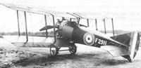
Nieuport Nighthawk
It has been said that the Nieuport Nighthawk fighter marked both the beginning and end of the Dragonfly engine saga, and its inclusion in this work at this point may be seen in the latter context as well as representing the transition from the wartime fighter genre to that of an austerity which characterized the beginnings of RAF re-equipment in peacetime. As already explained, aircraft such as the Sopwith Snipe and Bristol F.2B Fighter provided the main equipment of the fighter squadrons for half a dozen years after the Armistice - and the RAF could count itself fortunate that aircraft of such adequacy were available at all.
It will be recalled that in October 1917 the Air Board, in deciding upon a new fighter engine to power the proposed Camel replacement, selected the Bentley rotary. Five months later the Sopwith Snipe was announced as being the new fighter, and both aircraft and engine were ordered into large-scale production. That these decisions were correct, despite severe criticism at the time, was to be confirmed by subsequent events. A few days after the decision was taken to order the Bentley, the Air Board became aware of the ABC Dragonfly radial which promised to develop 40 per cent more power at a weight increase of only 26 per cent; not for a further ten months would these figures be seen to be wildly optimistic, while almost two years would pass before the extent of the Dragonfly’s design weaknesses were fully appreciated.
In the meantime the Air Board (and later the Air Ministry) raised two fighter Specifications in which it was implicit that the aircraft should be powered by the Dragonfly engine - and the aircraft designers needed no second bidding. The Nieuport Nighthawk was designed by Henry Folland, who called on his experience with both the S.E.5 and Nieuport B.N.1 to produce an exceptionally neat two-bay biplane, yet keeping an eye on the need for ease of manufacture. To this end he employed numerous S.E.5 components, and the tail assembly was virtually unchanged from that of the B.N.1.
While the performance of the Dragonfly was still far from being confirmed, Nieuport received an order for three Nighthawk prototypes (F2909-F2911) on 25 April 1918 to Air Board Specification A.1(C) - which was shortly to be consolidated within the new RAF Type I Specification. As a measure of the misplaced faith in the Dragonfly engine demonstrated by the Air Ministry that summer, it should be stated that orders totalling 11,050 engines (as a cost of almost £12m) were placed with thirteen manufacturers, far exceeding any previous order placed for an aircraft or aero engine.
Long before flight-cleared engines were delivered for the Nighthawk prototypes, the Air Ministry placed an order for 150 production aircraft on 28 August 1918 with Nieuport (England) Ltd, and there is no doubt that considerable progress had been made with airframe component manufacture by the date of the Armistice.
Records of the delivery dates of the first few flight-cleared Dragonfly I engines to Nieuport are convoluted, but it seems that the first example(s) may have arrived sometime in January or February, and it is said that a flight by the first prototype may have been made in April. (Doubt must be cast on this as it seems that flight clearance of all Dragonflies may have been temporarily withdrawn that month while bench-running engine temperatures were examined.) It is, however, known that F2911 was flying by the end of May, and that this aircraft was delivered to Martlesham Heath in June, remaining there for seven months, during which it flew less than a dozen hours.
In September that year the entire Dragonfly development and production programme was cancelled, contractors being required only to complete engines already more than half completed. In the event some 1,147 Dragonfly Is and IAs were delivered, the majority into storage; for the most part these had been produced by Vickers Ltd in its Crayford works.
The total number of production Nieuport Nighthawks completed (excluding the prototypes) was 70, plus 54 airframe spares without engines. Of these at least seven were delivered to the RAE at Farnborough for various engine tests - between them surviving more than a dozen forced landings - while about six underwent various trials at the A & AEE at Martlesham; one was used by the Marine Aircraft Experimental Establishment (MAEE) on the Isle of Grain for flotation tests before going on to Farnborough. Thirteen were taken over by the Gloucestershire Aircraft Company, as well as an unknown number of airframes from storage, and rebuilt as Mars VI/Nighthawks or Mars X/Nightjars. Some of the above, including at least three of the RAE aircraft, had their Dragonfly engines removed and replaced by Bristol Jupiter engines as part of the long and successful development of this engine. As far as can be discovered, the last Nieuport Nighthawk to remain flying was J2405, an original Dragonfly aircraft delivered to the RAE in January 1920; it took part in the Jupiter development, as well as tests with Fairey metal propellers before meeting its end in a forced landing on 30 September 1930.
Type: Single-engine, single-seat, two-bay biplane fighter.
Manufacturers: Nieuport (England) Ltd, Cricklewood; The Nieuport and General Aircraft Co Ltd, Cricklewood; The Gloucestershire Aircraft Co Ltd, Cheltenham, Glos.
Specification: Air Board Specification A.I(C) of 1917, later RAF Type I of 1918.
Powerplant: One 320hp ABC Dragonfly I; also Bristol Jupiter II.
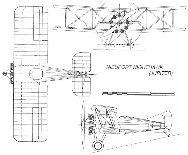
Dimensions: Span, 28ft 0in; length, 18ft 6in; height, 9ft 6in; wing area, 276 sq ft.
Weights: Tare, 1,500lb; all-up, 2,218lb.
Performance: Max speed, 151 mph at sea level, 134 mph at 15,000ft; climb to 10,000ft, 7 min 10 sec; service ceiling, 24,500ft; endurance, 3 hr.
Armament: Two synchronized 0.303in Vickers machine guns on upper nose decking.
Prototypes: Three, F2909-F2911 (F2909 may have been first flown in April 1919).
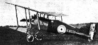
Production: A total of 286 Nieuport Nighthawks was ordered: H8513-H8662, J2392-J2462, J6801-J6848 and J6925-J6941; of these, 70 were completed with Dragonfly I or IA engines, and 54 airframes were assembled without engines or guns. The remainder were cancelled.
Показать полностью
W.Green, G.Swanborough The Complete Book of Fighters
NIEUPORT (& GENERAL) NIGHTHAWK UK
Work on the Nighthawk single-seat fighter was initiated by H P Folland in May 1918, the aircraft being designed to accept the new A.B.C. Dragonfly nine-cylinder radial engine. Three prototypes were ordered and the decision to proceed with quantity production was taken by the Air Ministry before the first of these had flown. Orders were placed with both the parent company and Gloucestershire Aircraft, but defects with the Dragonfly engine created delays in the programme and a prototype was not flown until after the Armistice. Production Nighthawks from both contractors appeared late in 1919, these being powered by the 320 hp Dragonfly, but none saw service with the RAF. When, in August 1920, Nieuport & General closed down, the rights to the Nighthawk, together with the services of its designer, were acquired by Gloucestershire Aircraft which continued development.
Max speed, 151 mph (243 km/h) at sea level.
Time to 10,000 ft (3050 m), 7.16 min.
Endurance, 3.0 hrs.
Empty weight, 1,500 lb (680 kg).
Loaded weight, 2,218 lb (1006 kg).
Span, 28 ft 0 in (8,53m).
Length, 18 ft 6 in (5,64 m).
Height, 9 ft 6 in (2,90 m).
Wing area, 276 sq ft (25,64 m2).
Показать полностью
J.Bruce British Aeroplanes 1914-1918 (Putnam)
Nieuport Nighthawk
THE second British Nieuport type was another single-seat fighter designed by H. P. Folland. This machine was named Nighthawk, and was powered by a 320 h.p. A.B.C. Dragonfly nine-cylinder radial engine.
Like the B.N.1, the Nighthawk was a two-bay biplane, but its bracing was more conventional: four pairs of parallel interplane struts connected the staggered wings. The tail-unit was virtually identical to that of the B.N.1, and retained the S.E.5 under-fin and tail-skid; but the fuselage was faired out to a rounded cross-section throughout its length. With an eye to rapid production, the Nighthawk incorporated several other S.E.5 parts: these included fuselage fittings, stick and rudder bar, and the axle and wheels.
In the air, the Nighthawk was supremely manoeuvrable, and its agility made it an excellent aerobatic mount. Its performance in terms of miles per hour and rate of climb was also extremely good, and there can be no doubt that it would have proved to be a good fighting aeroplane.
The Nighthawk went into production late in 1918, but it is perhaps fortunate that it did not see operational service. It has been said that, if the war had lasted some months longer than it did, the Dragonfly engine would have lost it for Britain at least.
It was, of course, almost inevitable that the Dragonfly should have been chosen for the Nighthawk; and in fact the Nighthawk was the first Dragonfly-powered aircraft to be ordered in quantity.
Mr Granville Bradshaw initiated design work on the Dragonfly after A.B.C. Motors, Ltd., had received an official invitation, in April, 1917, to submit designs for the 1918 engine programme. The company was given an order for three experimental engines, to be called Dragonfly, in August, 1917. The initial success of the smaller A.B.C. Wasp in its early trials encouraged Bradshaw to press his new design upon the Government. He claimed that the Dragonfly would deliver 340 h.p. for a weight of a little over 600 lb, and suggested that it would be preferable to build the Dragonfly rather than the Wasp. Like the Wasp, the Dragonfly was designed for ease of production; and it offered such great power that it was a very attractive proposition.
In October, 1917, the Air Board had decided to order the Bentley B.R.2 rotary engine in quantity, and by the middle of that month orders had been placed of sufficient size to ensure an ultimate production of 900 B.R.2 engines per month. Two days after the Air Board had made its decision, however, the Dragonfly was brought to the notice of the Board’s members.
Mindful of its unfortunate experiences arising out of the ordering of the untried Sunbeam Arab, the Board approached the Dragonfly with caution. The members felt that they could not afford to pass over an engine which seemed so full of promise; but they did not want to cancel or reduce the production of B.R.2s in favour of an untried design. The B.R.2 programme was therefore not disturbed, and Vickers, Ltd., were asked to produce the Dragonfly at their Crayford works as a first step.
As 1918 advanced, both the Air Board and the aircraft industry became more and more convinced that the Dragonfly was the best engine available, and large contracts were placed during the year. Altogether, 11,050 were ordered from thirteen contractors* and the ultimate intention was for the Dragonfly to supersede most other engines in production. The production programme was planned to ensure delivery of 4,135 Dragonflies by the end of June, 1919.
* The contractors and the numbers of Dragonfly engines ordered from each were these: Beardmore Aero Engine, Ltd.: 1,500; Crossley Motors, Ltd.: 1,000; Ransome, Sims & Jeffries: 500; F. W. Berwick & Co., Ltd.: 1,000; Belsize Motors, Ltd.: 1,000; Maudslay Engineering Co., Ltd.: 500; Vulcan Motor & Engineering Co., Ltd.: 600; Vickers, Ltd.: 1,000; Sheffield Simplex: 500; Guy Motors, Ltd.: 600; Clyno Engineering Co.: 500; Ruston, Proctor & Co., Ltd.: 1,500; Humber, Ltd.: 850.
After the engine was in production, however, it was found to be far from satisfactory. It was heavier than the original estimate; gave less power; and, worst of all, vibrated exceedingly badly in flight tests. Mechanical failure usually occurred after only a few hours’ flying. New pistons were fitted, and late in 1918 cylinder heads of the type developed at the Royal Aircraft Establishment by Professor A. H. Gibson and S. D. Heron were installed.
But the engine suffered from dynamic unbalance and synchronous torsional vibration in an extreme degree. The latter phenomenon was not understood in 1918, but it began to be realised that a complete re-design of the engine would have to be undertaken in order to cure the trouble. Before production contracts were cancelled, a total of 1,147 Dragonfly engines were produced; only twenty-three had been delivered by the end of 1918, but production continued into 1919.
Fortunately, the Armistice prevented the introduction of the Dragonfly into the service. In view of the extent to which the Air Board had committed itself to the engine, a continuation of the war would have brought catastrophe when the Dragonfly was introduced in large numbers. It was brought to the stage where it would run reliably for two and a half hours, and one school of thought held the view that it would be worthwhile to replace each aeroplane’s engine after each patrol in view of the power it delivered.
The failure of the A.B.C. Dragonfly led to the collapse of the Nighthawk production programme, for the aircraft had been ordered in large quantities before the engine’s shortcomings had been recognised as chronic. The Nighthawk went into limited service at home and in India, where No. 1 Squadron had a few in addition to its standard equipment of Snipes. The Nighthawk was occasionally fitted with the Bristol Jupiter engine in place of the erratic Dragonfly. Among experiments in which Nighthawks were used were those which were conducted with special crash-proof fuel tanks.
The type was withdrawn as obsolete in the spring of 1923, whereafter enough airframes were kept in store to provide sufficient conversions to Nightjars to maintain twelve machines for two years. The Nightjar was a modification of the basic Nighthawk for use from aircraft carriers, and was one of a series of Nighthawk developments made by the Gloucestershire Aircraft Co., Ltd., which took over the Nieuport design in 1920. Several Nighthawk airframes were converted into the various Gloucester Mars types. Fifty of the versions which were alternatively known as Sparrowhawks were supplied to Japan in 1922.
SPECIFICATION
Manufacturers: The Nieuport and General Aircraft Co., Ltd., Cricklewood, London, N.W. Other Contractors: The Gloucestershire Aircraft Co., Ltd., Cheltenham.
Power: 320 h.p. A.B.C. Dragonfly I.
Dimensions: Span: 28 ft. Length: 18 ft 6 in. Height: 9 ft 6 in. Chord: 5 ft 3 in. Gap: 4 ft 6 in. Span of tail: 9 ft. Airscrew diameter: 9 ft.
Areas: Wings: 276 sq ft. Ailerons: each 9-3 sq ft, total 37-2 sq ft. Tailplane: 18 sq ft. Elevators: 10 sq ft. Fin: 5-2 sq ft. Rudder: 5-3 sq ft.
Weights and Performance: No. of Trial Report: M.259. Date of Trial Report: July, 1919. Type of airscrew used on trial: A.B.8979. Weight empty: 1,500 lb. Military load: 218 lb. Pilot: 180 lb. Fuel and oil: 320 lb. Weight loaded: 2,218 lb. Maximum speed at ground level: 151 m.p.h.; at 6,500 ft: 140 m.p.h.; at 10,000 ft: 138-5 m.p.h.; at 15,000 ft: 134 m.p.h. Climb to 5,000 ft: 3 min; to 6,500 ft: 4 min 10 sec; to 10,000 ft: 7 min 10 sec; to 15,000 ft: 12 min 40 sec; to 20,000 ft: 20 min. Service ceiling: 24,500 ft. Endurance: 3 hours.
Tankage: Petrol: 40 gallons. Oil: 4 gallons.
Armament: Two fixed forward-firing Vickers machine-guns mounted on top of the fuselage and synchronised to fire through the revolving airscrew.
Service Use: R.A.F. Squadrons, Nos. 1 and 8 (post-war).
Serial Numbers: Between and about H.8533 and H.8544; between and about J.2405 and J.2416; between and about J.6925 and J.6930.
Notes on Individual Machines: H.8544, J.2405, J.2416 and J.6926 became Mars VI; H.8539 and J.6930 became Nightjars (Mars X); J.6925 was a Nighthawk used by No. 1 Squadron.
Показать полностью
O.Thetford Aircraft of the Royal Air Force since 1918 (Putnam)
Nieuport Nighthawk
Although the RAF acquired only a small batch of Nighthawks for trials, the type is of unusual significance in that it was to establish the pattern of Service fighter aircraft throughout the ’twenties and much of the ’thirties. The radial engine biplane remained the standard type of single-seat fighter in the RAF (with the exception of the Hawker Fury) until the Gladiator of 1937. The Nighthawk was the RAF’s first fighter powered by a stationary radial engine instead of the 1914-1918 type of rotary, and features of its design could be traced in a number of early Gloster fighters, notably the well-known Grebe.
The Nighthawk was originally produced to a 1918 specification for the RAF, Type I SS Fighter, a requirement which also brought forth such aircraft as the Sopwith Snark, Snapper and Snail, the AW Ara, the BAT Basilisk and Bantam, and the Westland Wagtail. The original Nighthawk, produced by the Nieuport and General Aircraft Co of Cricklewood, was powered by the 320hp ABC Dragonfly engine, one of the early radials. H P Folland, creator of the famous SE 5 fighter, was largely responsible for its design, and his interest continued when the type was taken over by the Gloucestershire Company (later Gloster Aircraft Co Ltd) in 1920. The original Dragonfly version appeared at the RAF Pageant in 1920 but, by 1923, when the celebrated dogfight occurred between a Boulton Paul Bourges and two fighters, the attacking Nighthawks, J2405 and J2416, had been been fitted with Jupiter radial engines.
After the failure of the Dragonfly engine (owing to apparently incurable unreliability), the first Nighthawk to be re-engined appears to have been H8534, which received a 325hp Jaguar II radial in November 1920. Four more Nighthawks were modified to Spec 35/22, two with Jaguar (H8544 and J6925) and two with Jupiter radials (J6926 and J6927). These Nighthawks were sent to Mesopotamia in 1923 for Service trials under tropical conditions. They were attached to No 1 Squadron (Snipes) and No 8 Squadron (DH 9A).
Production serial numbers allocated for the airframes included H8513-H8553, J2403-J2417, J6925-J6941, J6970 and J6971, many of which simply went into storage, and about eighteen became Nightjars.
TECHNICAL DATA (NIGHTHAWK)
Description: Single-seat fighter. Wooden structure, fabric covered. Maker's Designation: Mars VI.
Manufacturer: Gloucestershire Aircraft Co Ltd, Gloucester.
Powerplant: One 325hp Armstrong Siddeley Jaguar II, or 385hp Bristol Jupiter III.
Dimensions: Span, 28ft; length, 18ft; height, 9ft; wing area, 270sq ft.
Weights: Loaded (Jaguar), 2,550lb, (Jupiter), 2,270lb.
Performance: (Jaguar) Max speed, 150mph at sea level; climb, 21 min to 20,000ft; service ceiling, 27,000ft; endurance, 2hr. (Jupiter) Max speed, 148mph; climb, 16.5 min to 20,000ft.
Armament: Twin synchronised Vickers guns.
Показать полностью
H.King Armament of British Aircraft (Putnam)
Nieuport
Nighthawk. Being designed specifically for the A.B.C. Dragonfly radial engine, and having the petrol tanks flanking the pilot's cockpit and shaping the fuselage contours, the Nighthawk had a commodious fore-part. This enabled the two Vickers guns to be enclosed beneath the top decking, firing through ports located one on each side of the topmost cylinder of the Dragonfly engine. Aldis and ring-and-bead sights were bracketed to the upper centre-section. As on the contemporary Siddeley Siskin there was provision for 2.000 rounds of ammunition. It was stated that the head of the control column was of 'standard RAF type#, the ring being covered in rubber, having a magneto switch at the top and the two gun triggers at the centre. Design provision was made for four 20-lb bombs.
Показать полностью
Jane's All The World Aircraft 1919
The firm is under the direction of Major Heckstall-Smith late of the Royal Aircraft Factory.
During 1918 the firm produced a high-performance single-seat fighter, known as the " Nighthawk," which was ordered on a large scale by the R.A.F.
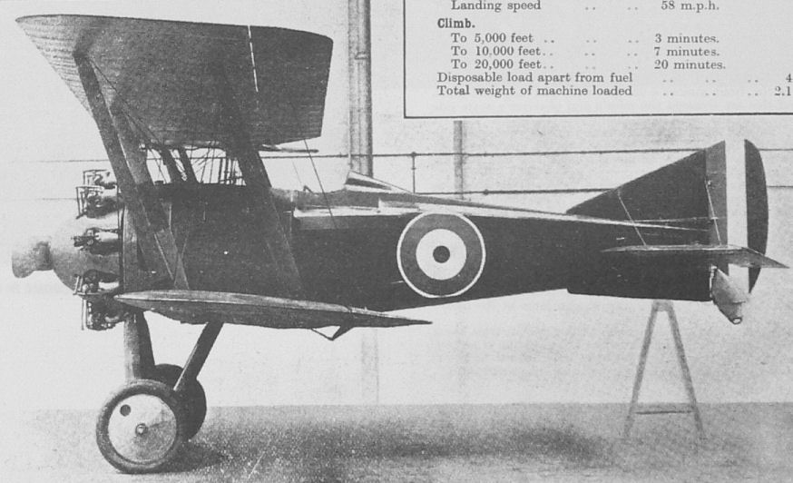
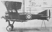
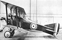
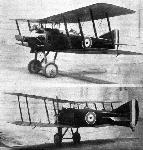
The accompanying photographs illustrate the British Nieuport "Nighthawk" with the 320 h.p. A.B.C. "Dragonfly" engine.
This machine is particularly interesting as having been built to the first specification issued by the Royal Air Force. When the R.A.F. decided that the time had come to concentrate on a limited number of types to finish up the war, they decided to concentrate for a single-seater fighter solely on the Nieuport "Nighthawk" for the "Dragonfly" engine.
The reasons why this machine was selected were:
(1) That it fulfilled the performance required.
(2) That it was fully up to the required strength as demonstrated by loading tests on every part of the machine.
(3) That the general arrangement of the machine gave the very best facilities to the pilot for fighting-namely: for position and accessibility of guns, instruments, etc., and the minimum blind area.
(4) Because the general design of the machine was for quick production and the fact that complete engineering drawings and schedules hod been prepared in advance.
The design was carried out by Mr. H. P. Folland, who is the chief engineer and designer to the Nieuport Company. Mr. Folland was assistant chief designer at the Royal Aircraft Factory, where ho carried out the designs of F.E.2 and S.E.5.
Prior to the war, when Lieut.-Col. J. E. B. Seely, who was then Secretary of State for War, wished to make a world's record on behalf of the Royal Aircraft Factory, ho instructed the superintendent of the R.A.F. to produce a machine for this purpose. This machine was known as S.E 4, and was fitted with 160 h.p. 18 cylinder Gnome engine. The design of this machine was carried out by Mr. Folland, and the machine was flown by Mai. J. M. Salmond (now Major-General and K.C.B.), and, as mentioned in the House of Commons in 1914, the machine made a speed of 135 m.p.h. and climbed the first 1,500 ft. in one minute.
Major S. Heckstall Smith, general manager of the Nieuport Company, was at that time Assistant Superintendent at the R.A.F., and was largely responsible for such successes as the factory produced. The " Nighthawk " is a marked advance in detail design and construction on any of the R.A.F. work, and both he and Mr. Folland deserve to be congratulated on its production.
As will be seen, the machine somewhat resembles the Sopwith "Snipe" in general appearance and dimensions. It is designed as a production job, and a quantity of the fittings which are used in S.E.5s have been worked into the design, because these are stock fittings and can be procured easily and in quantities.
The photographs show that the machine is eyeable, and that it gives one an impression of speed. It will be interesting to notice how the official performance of the machine works out in practice.
Particulars of this machine are given in the following table:
Type of machine Fighting Scout.
Name or type No. of machine British Nieuport "Nighthawk"
Purpose for which intended Fighting, airship destruction, convoying.
Span 28 ft.
Gap, maximum and minimum 4 ft. 6 In.
Overall length 18 ft. 6 In.
Maximum height 9 ft. 6 in.
Chord 5 ft. 3 In.
Total surface of wings 270 sq. ft.
Span of tall 9 ft.
Total area of tail 28 sq. ft.
Area of elevators 10 sq. ft.
Area of rudder 5 ft 3 In.
Area of fin 5 ft. 2 In.
Area of each aileron and total area 9.3 each; total 37.2 sq. ft.
Maximum cross section of body 10 sq. ft.
Horizontal area of body 46 sq. ft.
Vertical area of body 49 sq. ft.
Engine type and h.p. A.B.C. "Dragonfly," 320 h.p.
Airscrew, diam., pitch and revs. 9 ft. dia.; 7 ft. pitch; 1,650 revs.
Weight of machine empty 1,500 lbs.
Load per sq. ft. 7.75 lbs.
Weight per h.p. 6.62 lbs.
Tank capacity in hours 3 hours at 20,000 feet.
Tank capacity in gallons 40 petrol, 4 oil.
Performance.
Speed low down 151 m.p.h.
Speed at 10,000 feet 140 m.p.h.
Speed at 20,000 feet 121 m.p.h.
Landing speed 58 m.p.h.
Climb.
To 5,000 feet 3 minutes.
To 10,000 feet 7 minutes.
To 20,000 feet 20 minutes.
Disposable load apart from fuel 400 lbs.
Total weight of machine loaded 2.120 lbs.
Показать полностью
A.Jackson British Civil Aircraft since 1919 vol.3 (Putnam)
Nieuport Nighthawk
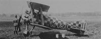
Two seater designed by H. P. Folland, powered by one 320 h.p. A.B.C. Dragonfly I and built from Nighthawk single seat fighter components by the Nieuport and General Aircraft Co. Ltd. at Cricklewood 1919. One British civil aircraft only: K-151, c/n L.C.l No.l, flown in the Aerial Derby, Hendon, 21.6.19 by L. R. Tait-Cox, forced landed at West Thurrock, Essex. Became G-EAEQ, C. of A. 7.7.19, made first newspaper flight in India, from Bombay to Poona 2.20. Sold in India 9.20.
Span, 28 ft. 0 in. Length, 18 ft. 0 in. Tare wt., 1,500 lb. A.U.W., 2,180 lb. Max. speed, 138 m.p.h.
Nieuport Nieuhawk
Single seat wooden racing and demonstration aircraft powered by one 320 h.p. A.B.C. Dragonfly I, designed by H. P. Folland and built at Cricklewood 1919 by the Nieuport and General Aircraft Co. Ltd. One aircraft only: G-EAJY, c/n L.C.l No.2, first flown 3.9.19, fourth at 132-67 m.p.h. in the Aerial Derby, Hendon, 24.7.20 piloted by J. H. James. Forced landed after completing one lap of the Aerial Derby 16.7.21 at 142-6 m.p.h. piloted by Flt. Lt. J. Noakes. Sold 1921 to С. P. B. Ogilvie, Willesden.
Span, 26 ft. 0 in. Length, 18 ft. 6 in. A.U.W., 2,120 lb. Max. speed, 151 m.p.h.
Показать полностью
Журнал Flight
Flight, January 16, 1919.
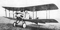
THE NIEUPORT "NIGHTHAWK"
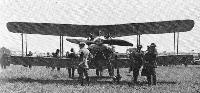
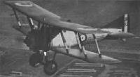
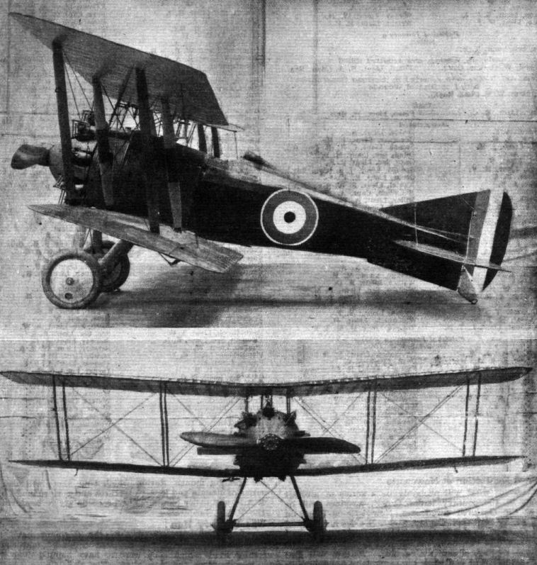
AMONG the machines of which it has not hitherto been permissible to give any particulars is the little tractor scout called the "Nighthawk," designed and built by the Nieuport and General Aircraft Co., Ltd., of Cricklewood. We are pleased to be able to publish this week photographs of this interesting machine.
The first Nieuport Nighthawk was built and tested some time ago, and the machine represented in the accompanying photographs is the second of the type to be constructed. It is expected to have a speed of 135 m.p.h. at 10,000 ft. and a ceiling of somewhere about 28,000 ft. The engine fitted is the famous A.B.C. "Dragonfly" of 320 h.p.
The Nieuport Nighthawk is of particular interest as having been built to the first specifications issued by the Royal Air Force. When it was decided that the time had come for concentrating on a limited number of types to finish the war, the Nieuport Nighthawk was included in the single-seater fighter class, to be fitted with the "Dragonfly" engine. The points in favour of its adoption are that it has the performance required, that its structural strength has been proved by loading tests on every part of the machine; that the general arrangement of the machine is such as to give the best possible facilities to the pilot for fighting, such as a minimum of blind area and a good position and accessibility for guns, instruments, &c, and that the detail design has been got out with a view to quick and easy production. It might also be mentioned, as being somewhat out of the ordinary, that complete engineering drawings and schedules had been prepared beforehand, while materials' lists could be issued to contractors from the beginning, thus saving much valuable time.
We might mention that the design was carried out by Mr. H. P. Folland, chief engineer and designer of the Nieuport and General Aircraft Co., who was formerly Assistant Chief Designer at the Royal Aircraft Factory, where he got out the designs for the F.E.2 and the S.E.5. Another machine for which Mr. Folland was responsible was the S.E.4, a small tractor scout with stream line body and single I struts, fitted with 160 h.p. Gnome engine. This machine was flown by Maj.-Gen. Sir J. M. Salmond in 1914, and is said to have developed a speed of 135 m.p.h., while climbing the first 1,500 ft. in one minute. Two photographs of this machine appeared in "FLIGHT" of January 20, 1916. The S.E.4 was not, however, adopted for the Flying Services.
Flight, June 26, 1919.
THE AERIAL DERBY
THE MACHINES
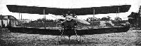
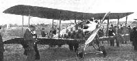
No. 11. - The Nieuport L.C. 1, 320 h.p. A.B.C. Dragonfly
Generally speaking, the Nieuport biplane entered for the Aerial Derby was very similar to the standard Nieuport Nighthawk. It is, however, designed as a two-seater, although in the race it had the passenger's cockpit covered in. As recorded elsewhere in this issue, the machine, which was piloted by Lieut. L. R. Tait-Cox, had engine trouble and was obliged to retire from the race, but this is not necessarily any criterion of the capabilities of the machine. The cause of the engine trouble was one that might have happened to any engine, on any machine, and certainly the Nieuport L.C. 1 shows a very good performance, both as regards speed, climb and manoeuvrability. It might be mentioned that the letters L.C. 1 stand for Land Commercial No. 1. A feature of the L.C. 1, which it shares with the Nieuport Nighthawk, is the extensive employment of wood, the number of metal parts having been reduced as far as possible, while in no single instance are any of the few metal fittings that carry loads built up by the use of welding. In spite of the relatively small cross section of the fuselage, the cockpits are very roomy, and the arrangement of the various instruments, etc., has been most carefully thought out.
Flight, November 27, 1919.
THE NIEUPORT "NIGHTHAWK"
As a type, the "Nighthawk," designed and built by the British Nieuport and General Aircraft Co., Ltd., of Cricklewood, belongs to the single-seater fighter class, of the modern type in which the size of engine fitted has resulted in the employment of two pairs of inter-plane struts on each side. It is a machine which was just beginning to come through in quantities when the Armistice was signed, and, had the War continued, it would doubtlessly have played a considerable part in the air-fighting on the Western Front. Its performance is excellent, and its detail design has been most carefully thought out with a view to ease of production in quantities.
In reviewing the Nieuport "Nighthawk," it is a matter of some difficulty to make up one's mind as to whether the machine is most remarkable for its performance and manoeuvrability, or for its detail construction. Perhaps on balance construction has it, and this is said with no intention to belittle the aerodynamic side of the design. It has, however, been proved that performance is chiefly a matter of loading per horse-power, and, given reasonably careful design, machines do not differ greatly when judged on this basis. There are still the questions of stability and manoeuvrability, and in the "Nighthawk" is found as great an amount of stability as is compatible with the extreme manoeuvrability demanded of a machine which is to be used for fighting.
It is, however, in the matter of detail design, that there is the greatest scope for originality, as well as for sound engineering practice. In this respect the "Nighthawk" offers many interesting features, and, by the courtesy of the designers, we have been able to examine in detail, and sketch, some of the constructional details that go to make the "Nighthawk" such an interesting structure.
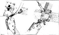
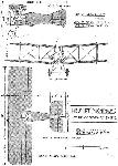
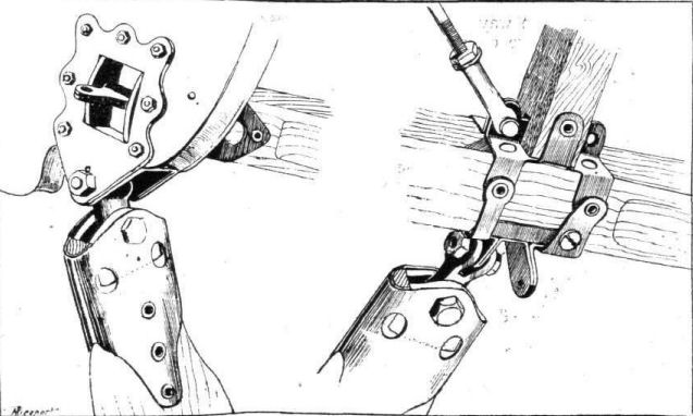
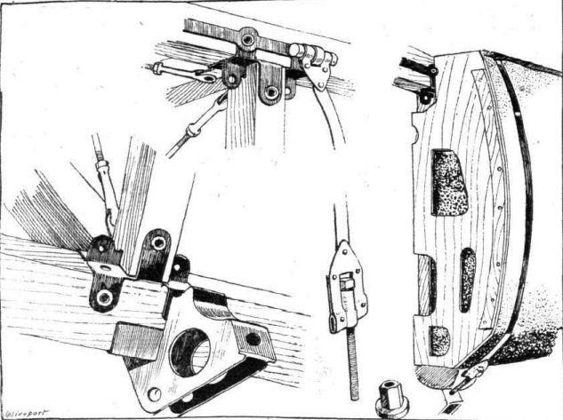
A feature which is noticed at once on examining this machine is the absence of welding. Mr. H. P. Folland, chief engineer and designer, has managed to do without this, almost entirely. In its place, where different pieces of metal have to be joined together, riveting and dip-brazing have been employed. The only parts that have been subject to welding are such as do not carry any load, and where, therefore, welding is perfectly safe. Another feature of the "Nighthawk" is the extensive employment of tubular rivets instead of threaded bolts. Special tools have been designed for the production of these tubular rivets, the manufacture of which is carried out in an extremely efficient manner. The use of these rivets instead of threaded bolts has several advantages in addition to cheapness. For instance, the small flanged ends of the rivets project above the wood to a much smaller extent than do the nuts and bolt-heads of ordinary threaded bolts. Where a fabric covering comes into contact with the rivets, this results in a smooth surface without the unsightly projections caused by the bolt-heads.
The fuselage is a girder structure of rectangular section, to which are added, as regards the front part of the body, streamline fairings built up of light longitudinal stringers supported on light three-ply formers. The four main longerons are of ash throughout, lightened in some places by spindling. The vertical and horizontal struts are of spruce, of square section, tapered towards the ends, where they fit into circular sockets. The cross-bracing is by tie-rods, the forked ends of which fit over lugs on the very simple fuselage fittings.
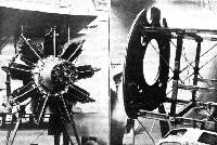
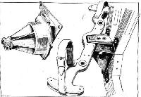
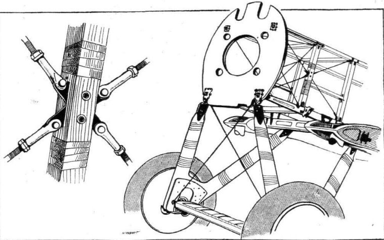
In the nose the fuselage terminates in a roughly circular engine plate made of multi-ply wood, reinforced on its front face by a circular strip of steel, through which pass the bolts securing the A.B.C. "Dragonfly" engine to the plate. The attachment of this engine plate to the longerons is by very substantial fittings, the pull on the upper ones of which is transmitted via steel strips along the sides of the top longerons to the first vertical strut fitting, to which the strips are secured. Owing to the weight of the engine, the lower fittings are not subject to the same amount of pull, and the lower longerons are not, therefore, thus reinforced. The multi-ply engine plate is lightened by cutting away portions of it, and has, further, at the top two notches for the machine guns.
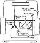
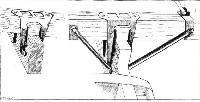
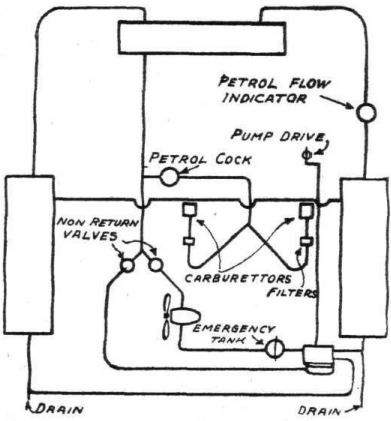
The arrangement of the petrol tanks is unusual, and very well thought out. Instead of carrying them inside the body, where they are in the way, and where, moreover, they are difficult to get at, the tanks are housed in the streamline fairings on the sides of the body. Here, if a tank becomes damaged during a fight or through any other cause, by simply removing the aluminium covering and undoing the straps securing the tanks, these can be removed and repaired, or replaced by new ones. There are two of these side tanks - of the Imber variety of course - and a third, the gravity tank, is housed in the centre section of the top plane, where it rests on a three-ply floor, and is held in place by the diagonal cross-bracing to the centre section. The manner of supporting the tanks, and of securing them in place, by straps, is illustrated by some of the accompanying sketches.
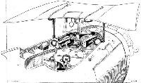
The pilot's cockpit, in spite of the fact that the fuselage is of the ordinary girder type with external fairings and of only ordinary maximum cross-section, is extremely roomy, surprisingly so, and the disposition of the various instruments as well as of the two machine guns, has been most carefully thought out, so that all are clearly visible and within easy reach, without, however, being in the way to the slightest extent. The machine guns are easily accessible, yet are sufficiently far removed from the pilot to avoid any danger of him being thrown against them in the case of a bad landing. The wind screen is in the form of a Vee of narrow angle, terminating at the back in two narrow aluminium strips, which are given a slight outward curve so as to deflect the air, even when the pilot is looking slightly past the sides of the wind-screen. In case of the screen becoming covered with moisture, therefore, the pilot is still able, by leaning his head slightly to one side, to see past the screen without being worried by any strong draught of air. The cartridge cases are mounted just in front of the dashboard, and are provided with chutes through the floor of the fuselage.
The controls, as regards type, are of the usual form, but in detail design show several interesting features. Thus the control lever is mounted on ball-bearings in an aluminium casting of the form shown in one of our sketches. This makes a very sound, strong, and at the same time simple, job. The foot-bar is of wood, covered with aluminium plates top and bottom, as shown in the sketch. An interesting feature of the foot-bar is the ease with which adjustment for different pilots can be made. It will be seen that the shape of the foot-bar itself provides means for varying the distance from the pilot's seat by reversing the bar, while further adjustment is provided by the bolt holes in the bracket supporting it.
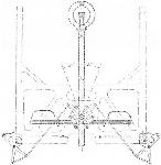
The tail-plane trimming gear is of somewhat unusual type, the lever operating it being held in any desired place by cables passing over pulleys, no notched quadrant or similar locking device being needed. The tail-plane is hinged around its rear spar, the front spar being provided with fittings which engage with the blocks on the two rotatable worms as shown in some of the accompanying sketches. The whole arrangement is well thought out and impresses one as being a very good engineering job.
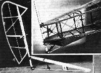
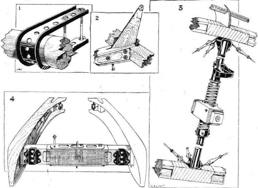
The under-carriage is of the usual "Vee" type, with struts of wood, the apices of the vees being connected by two transverse members, also of wood, between which rests the axle, which is housed in a fairing of three-ply, the top of which is hinged to allow of the travel of the axle when the machine is taxying. Springing is by rubber cord shock-absorbers, and the axle is free to move in an opening cut in the spruce block which fills the angle at the lower end of the vees. Aluminium plates cover and reinforce the vees at their lower end. The method of attaching the under-carriage struts to the body is shown in two of our sketches. The front chassis strut is secured to the fitting on the engine bearer at the point where occurs the attachment of the lower longeron. The rear chassis strut is bolted to one of the fuselage strut fittings, as shown in the sketch. Both are pin-jointed, as will be seen, so as to adapt themselves to any small irregularity in the fitting up of the vees. To those who have had any experience of welding up together an undercarriage built of streamline steel tubes, in which the accuracy has to be on the right side of half a degree, this point will specially appeal.
The tail skid is of similar type to that fitted on the S.E. 5 biplanes, steering with, but forming no part of, the rudder. The tail plane, which is of symmetrical cross-section, is so mounted as to be capable of having its angle of incidence altered during flight. The rear spar forms the hinge, and one of our photographs shows, incidentally, the manner in which the rear spar bearings are supported. Instead of being mounted on the vertical struts, the spar bearings occur between struts, and are pivoted on a short length of steel tube held in sheet steel lugs in the middle of the side-bracing. The elevator has a circular leading edge of wood, to which the elevator ribs are attached by wood blocks and aluminium strips. The U-clips which form the supports for the elevator leading edge are of channel section, as shown in one of our sketches. To protect the wooden leading edge from wear it is surrounded by a thin brass sheet. At certain points this brass binding is flanged so as to locate the elevator, the other bindings being smooth, thus allowing a fair amount of latitude in workmanship without endangering the smooth working of the elevator.
The vertical fins, of which there is one above and one below the fuselage, as well as the rudder, are of very light wood construction, the trailing edge of the rudder being of sheet aluminium bent to a U-section with small flanges turned inwards, which gives great lateral rigidity to the trailing edge.
In general construction the main planes follow usual practice. The main spars are of spruce, spindled out to an I-section. The ordinary ribs are very lightly built, of spruce webs and flanges. The compression ribs are of I-section spruce, with additional flanges glued to top and bottom. In between the compression ribs that are in line with the interplane struts are other ribs of the box type, as there is a double bay of internal drag bracing between each pair of struts. As the rear spar is situated fairly far forward in the wing section, the ailerons are not hinged to the rear main spar, but to a false spar some distance farther back. Ailerons are fitted to both top and bottom planes, and the controls are in the form of R.A.F. wires inside the wings. These wires pass through fibre guides, and where they have to pass over pulleys on their way back to the crank levers a short length of stranded cable is used.
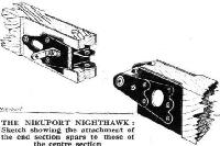
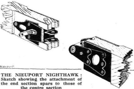
The attachment of the end sections to the centre sections allows of a certain amount of play, as will be seen from one of the sketches. The ends of the centre section spars carry two horizontal lugs which pass on each side of the horizontal trunnion on the end of the end section spar. A vertical bolt secures the two together, and while the front spar trunnion is the full length of the distance between the sheet-steel lugs, that on the rear spar is somewhat shorter, so that any slight variation in the distance between the spars does not prevent the two parts from being bolted together.
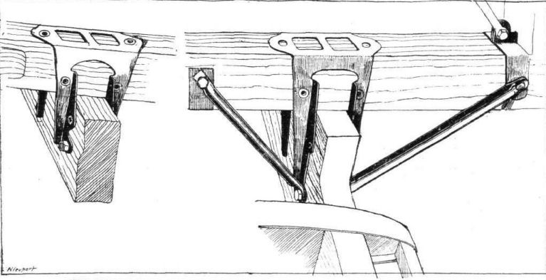
An interesting feature of the centre sections is that they have a slight dihedral angle This does not extend over their entire length, the central portion being horizontal, while the ends are slightly turned up. The top centre section is supported by four tubular struts, streamlined with wood. The manner of securing the lower centre section spars to the lower fuselage longerons is illustrated in a sketch. The front spar is held by a simple clip, while the rear spar, which occurs between two vertical struts, has its support reinforced by sloping tubes going to the points on the longeron where occur the struts. In this manner there is no fear of the lower longeron deflecting under the load of the rear spar.
The wing bracing is everywhere in the form of R.A.F. wires. The only remarkable feature of the bracing is that in the outer bay there is only one anti-lift wire, running from the top of the rear inner strut to the bottom of the outer front strut. There are two lift wires, which, in the outer bay, are in the plane of the struts, while in the inner bay they run from front and rear chassis strut attachments respectively.
The main characteristics of the Nieuport "Nighthawk" are as follows: Weight, empty, 1,700 lbs.; useful load, 400 lbs.; total weight, 2 100 lbs.; load per sq. ft., 7.8 lbs.; load per horsepower, 6.6 lbs; speed at 5,000 ft., 150 m.p.h.; speed at 20,000 ft. 130 m.p.h.; climb to 20,000 ft. in 20 minutes; ceiling, 29,000 ft.; endurance, 3 hours at 20,000 ft., including climb; radius of action, 180 miles at 20,000 ft.
Показать полностью