Описание
Страна: Германия
Год: 1917
Two-seat reconnaissance and artillery observation
Варианты
- LVG - C.V - 1917 - Германия
- LVG - C.VI - 1918 - Германия
- LVG - C.VIII - 1918 - Германия
- LVG - P.I / P.II - 1919 - Германия
- LVG - W.I / W.II - 1919 - Германия
- В.Обухович, А.Никифоров Самолеты Первой Мировой войны
- А.Александров, Г.Петров Крылатые пленники России
- O.Thetford, P.Gray German Aircraft of the First World War (Putnam)
- J.Stroud European Transport Aircraft since 1910 (Putnam)
- J.Herris LVG Aircraft of WWI. Vol.1: B-Types & C.I (A Centennial Perspective on Great War Airplanes 34)
- J.Herris LVG Aircraft of WWI. Vol.2: Types C.II - C.V (A Centennial Perspective on Great War Airplanes 35)
- J.Herris LVG Aircraft of WWI. Vol.3: Types C.VI-C.XI & Fighters (A Centennial Perspective on Great War Airplanes 36)
- M.Dusing German Aviation Industry in WWI. Volume 1 (A Centennial Perspective on Great War Airplanes 84)
- Журнал Flight
-
J.Herris - LVG Aircraft of WWI. Volume 2: Types C.II-C.V /Centennial Perspective/ (35)
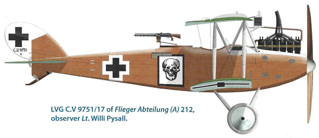
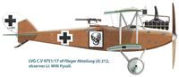
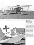
LVG C.V 9751/17 of Flieger Abteilung (A) 212, observer Lt. Willi Pysall.
-
J.Herris - LVG Aircraft of WWI. Volume 3: Types C.VI-C.XI & Fighters /Centennial Perspective/ (36)
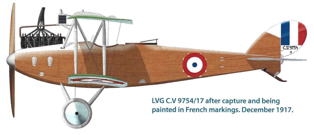
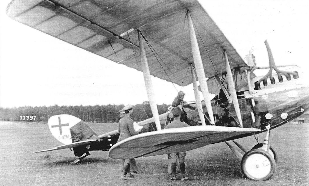
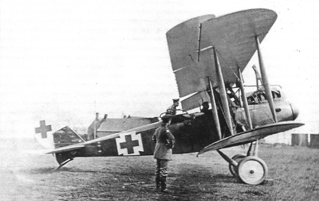
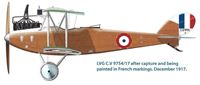
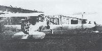
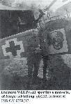
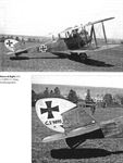
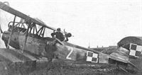
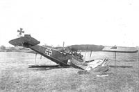
LVG C.V 9754/17 after capture and being painted in French markings. December 1917.
-
J.Herris - LVG Aircraft of WWI. Volume 2: Types C.II-C.V /Centennial Perspective/ (35)
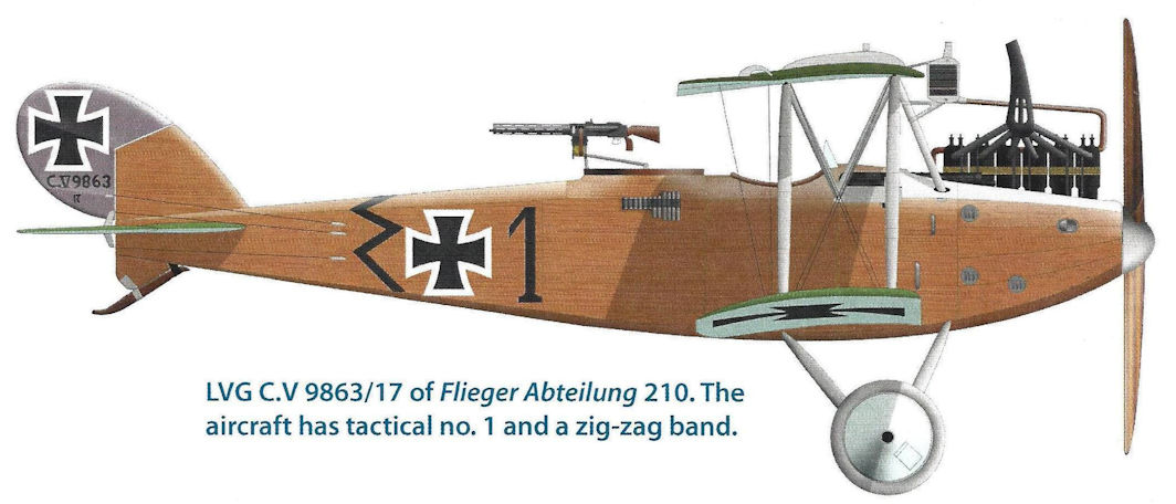
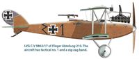
LVG C.V 9863/17 of FliegerAbteilung 210. The aircraft has tactical no. 1 and a zig-zag band.
-
J.Herris - LVG Aircraft of WWI. Volume 2: Types C.II-C.V /Centennial Perspective/ (35)
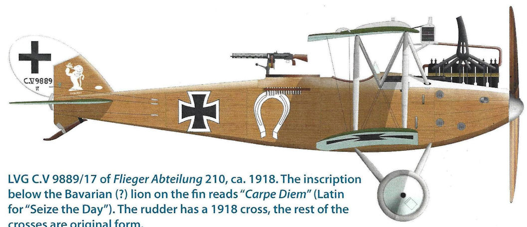
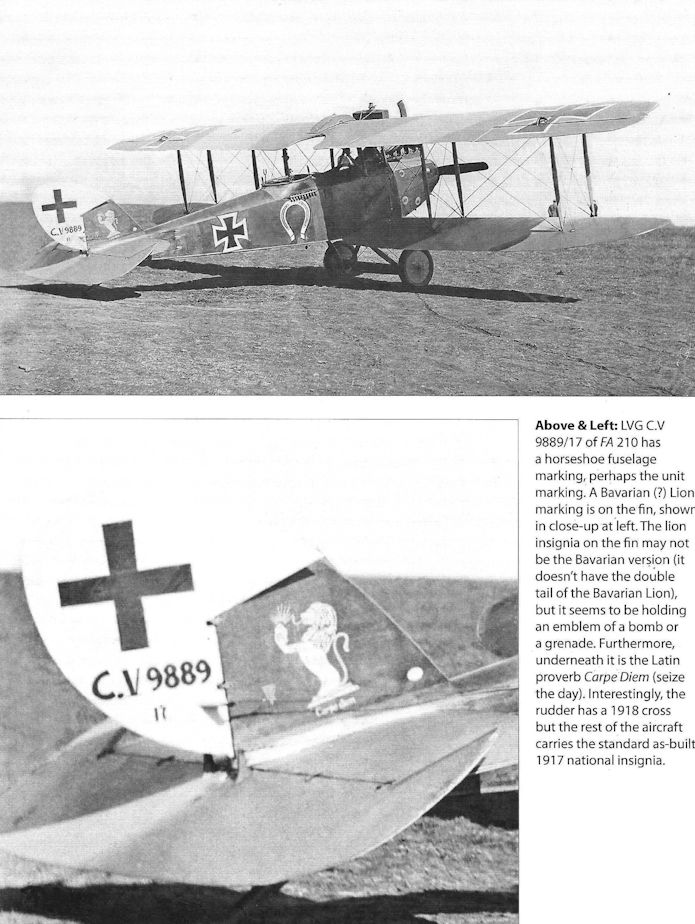
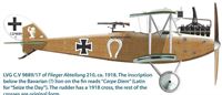
LVG C.V 9889/17 of FliegerAbteilung 210, ca. 1918. The inscription below the Bavarian (?) lion on the fin reads "Carpe Diem" (Latin for "Seize the Day"). The rudder has a 1918 cross, the rest of the crosses are original form.
-
J.Herris - LVG Aircraft of WWI. Volume 2: Types C.II-C.V /Centennial Perspective/ (35)
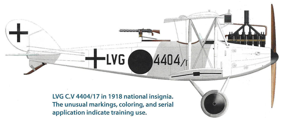
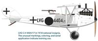
LVG C.V 4404/17 (14404/17 ???) in 1918 national insignia. The unusual markings, coloring, and serial application indicate training use.
-
J.Herris - LVG Aircraft of WWI. Volume 2: Types C.II-C.V /Centennial Perspective/ (35)
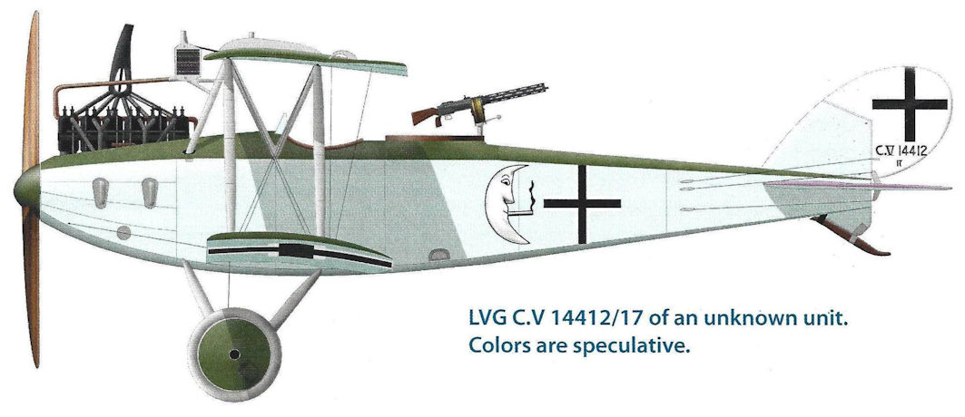
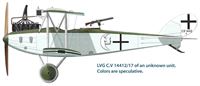
LVG C.V 14412/17 of an unknown unit. Colors are speculative.
-
J.Herris - LVG Aircraft of WWI. Volume 3: Types C.VI-C.XI & Fighters /Centennial Perspective/ (36)
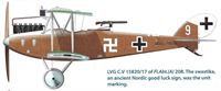
LVG C.V 15820/17 of FI.Abt.(A) 208. The swastika, an ancient Nordic good luck sign, was the unit marking.
-
J.Herris - LVG Aircraft of WWI. Volume 3: Types C.VI-C.XI & Fighters /Centennial Perspective/ (36)
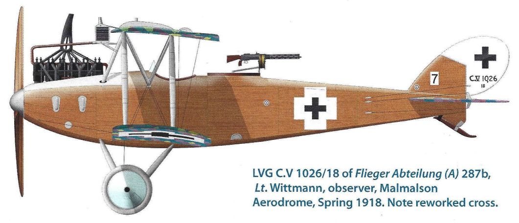
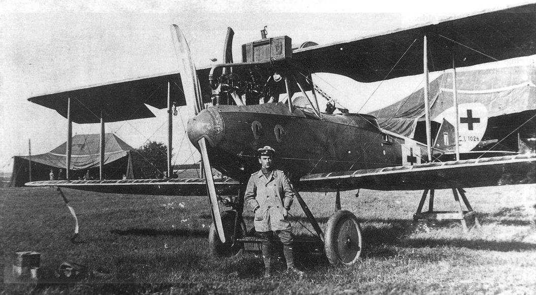
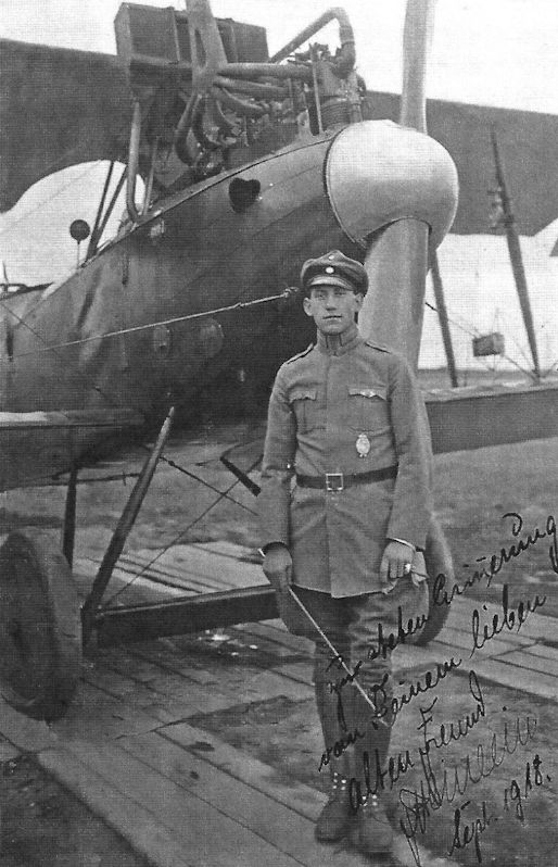
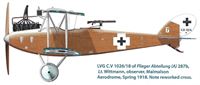
LVG C.V 1026/18 of Flieger Abteilung (A) 287b, Lt. Wittmann, observer, Malmalson Aerodrome, Spring 1918. Note reworked cross.
-

J.Herris - LVG Aircraft of WWI. Volume 3: Types C.VI-C.XI & Fighters /Centennial Perspective/ (36)
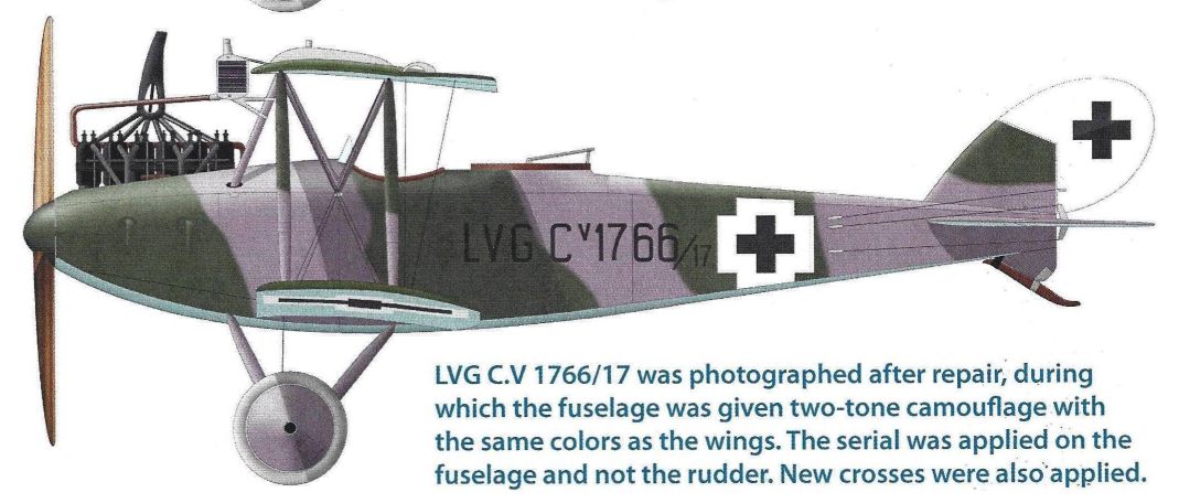
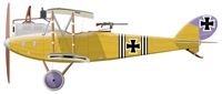
LVG C.V 1766/17 (1766/18 ???) was photographed after repair, during which the fuselage was given two-tone camouflage with the same colors as the wings. The serial was applied on the fuselage and not the rudder. New crosses were also applied.
-
J.Herris - Development of German Warplanes in WWI /Centennial Perspective/ (1)
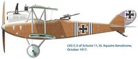
This LVG C.V of Schusta 11 in October 1917 displays black and white fuselage unit markings over the standard factory finish.
-
J.Herris - LVG Aircraft of WWI. Volume 2: Types C.II-C.V /Centennial Perspective/ (35)
LVG C.V of Schusta 11, St. Aquaire Aerodrome, October 1917.
-
J.Herris - LVG Aircraft of WWI. Volume 2: Types C.II-C.V /Centennial Perspective/ (35)
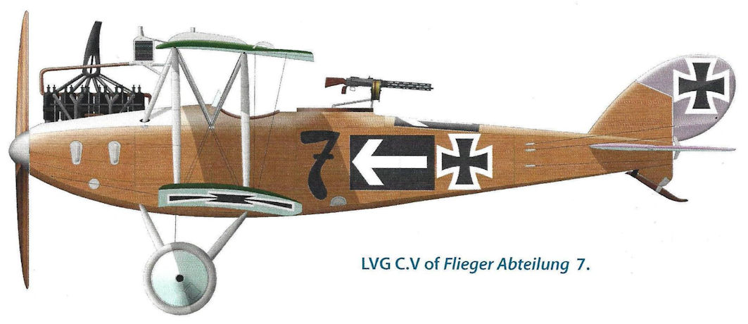
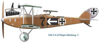
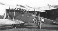
LVG C.V of Flieger Abteilung 7.
-
J.Herris - LVG Aircraft of WWI. Volume 2: Types C.II-C.V /Centennial Perspective/ (35)
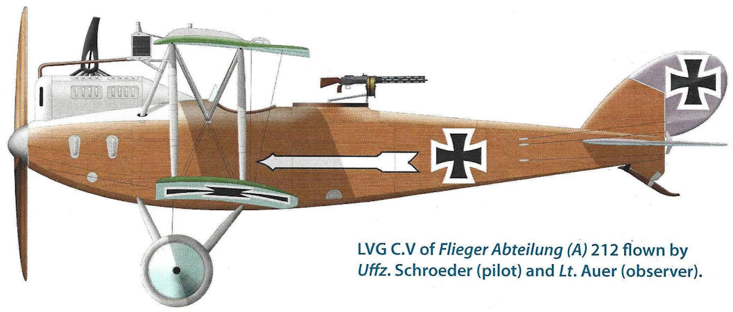
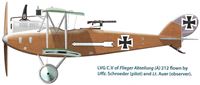
LVG C.V of Flieger Abteilung (A) 212 flown by Uffz. Schroeder (pilot) and Lt. Auer (observer).
-
J.Herris - LVG Aircraft of WWI. Volume 2: Types C.II-C.V /Centennial Perspective/ (35)
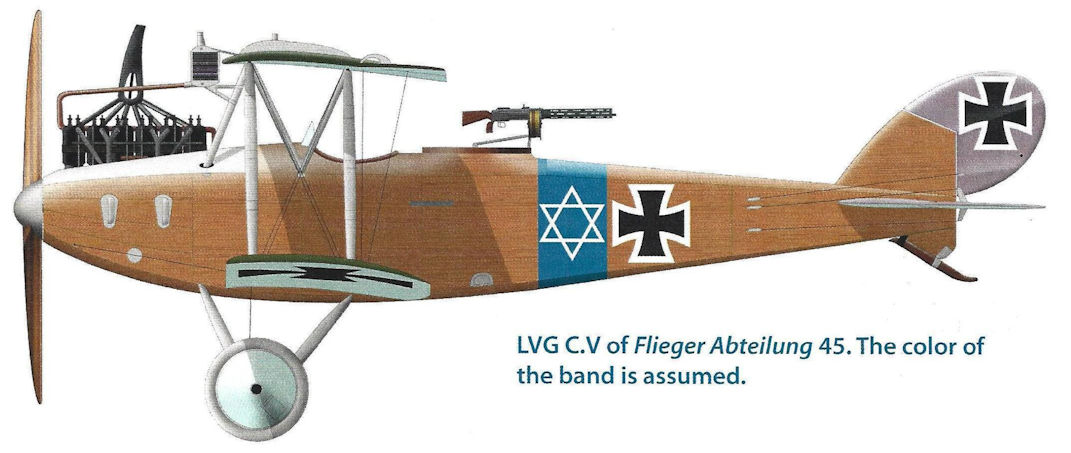
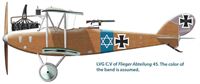
LVG C.V of Fliegerabteilung 45 with blue band and brewer's star personal marking. The color of the band is assumed.
-
J.Herris - LVG Aircraft of WWI. Volume 2: Types C.II-C.V /Centennial Perspective/ (35)
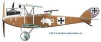
LVG C.V of Marine Schusta I or II.
-
J.Herris - LVG Aircraft of WWI. Volume 2: Types C.II-C.V /Centennial Perspective/ (35)
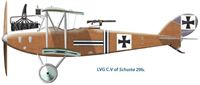
LVG C.V of Schusta 29b.
-
J.Herris - LVG Aircraft of WWI. Volume 2: Types C.II-C.V /Centennial Perspective/ (35)
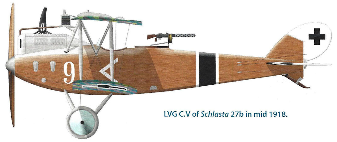
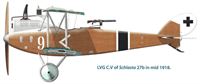
LVG C.V of Schlasta 27b in mid 1918.
-
J.Herris - LVG Aircraft of WWI. Volume 2: Types C.II-C.V /Centennial Perspective/ (35)
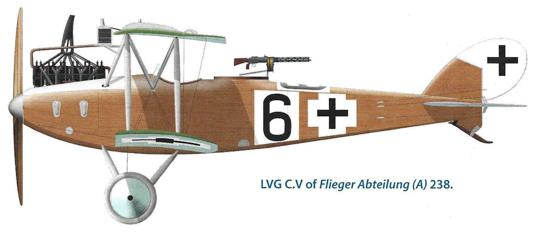
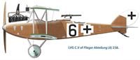
LVG C.V of Flieger Abteilung (A) 238.
-

J.Herris - LVG Aircraft of WWI. Volume 2: Types C.II-C.V /Centennial Perspective/ (35)
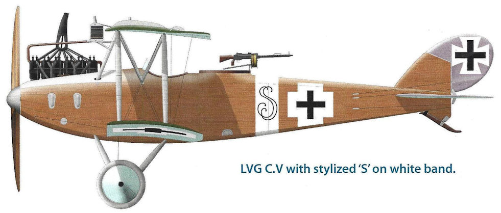
LVG C.V with stylized 'S' on white band.
-
J.Herris - LVG Aircraft of WWI. Volume 2: Types C.II-C.V /Centennial Perspective/ (35)
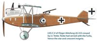
LVG C.V of Flieger Abteilung (A) 253 crewed by Lt. Teske. Teske had served with the Turks, hence the star and crescent insignia.
-
J.Herris - LVG Aircraft of WWI. Volume 2: Types C.II-C.V /Centennial Perspective/ (35)
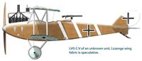
LVG C.V of an unknown unit. Lozenge wing fabric is speculative.
-

J.Herris - LVG Aircraft of WWI. Volume 2: Types C.II-C.V /Centennial Perspective/ (35)
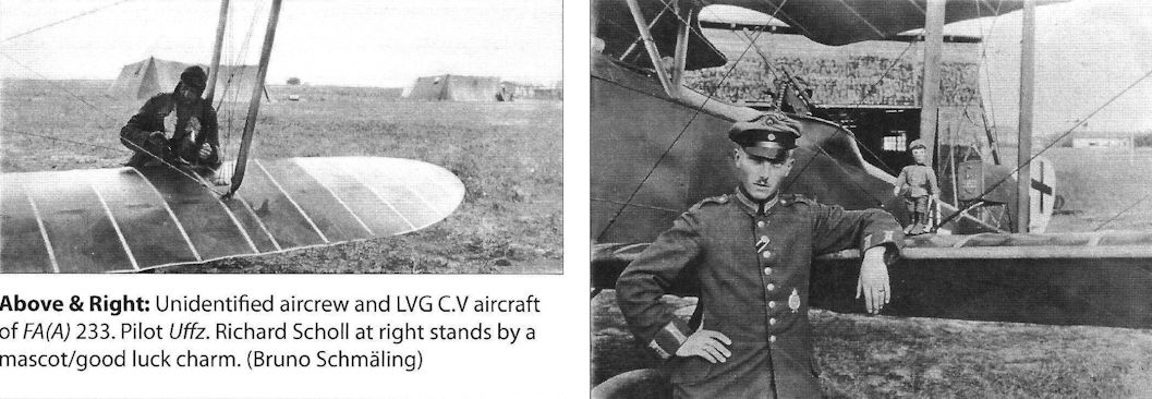
LVG C.V of FliegerAbteilung (A) 233. The nose stripes are a unit marking.
-
J.Herris - LVG Aircraft of WWI. Volume 2: Types C.II-C.V /Centennial Perspective/ (35)
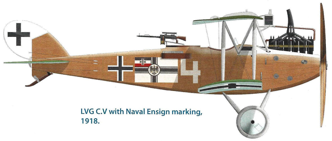
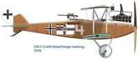
LVG C.V with Naval Ensign marking, 1918.
-
J.Herris - LVG Aircraft of WWI. Volume 2: Types C.II-C.V /Centennial Perspective/ (35)
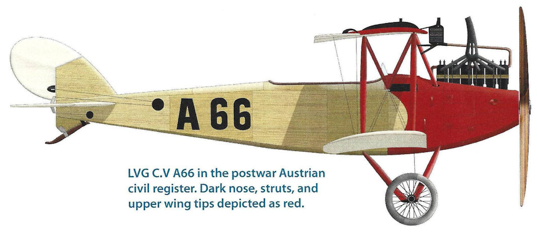
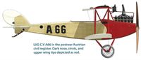
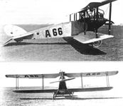
LVG C.V A66 in the postwar Austrian civil register. Dark nose, struts, and upper wing tips depicted as red.
-
J.Herris - LVG Aircraft of WWI. Volume 2: Types C.II-C.V /Centennial Perspective/ (35)
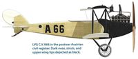
LVG C.V A66 in the postwar Austrian civil register. Dark nose, struts, and upper wing tips depicted as black.
-

J.Herris - LVG Aircraft of WWI. Volume 2: Types C.II-C.V /Centennial Perspective/ (35)
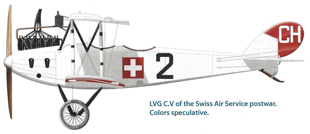
LVG C.V of the Swiss Air Service postwar. Colors speculative.
-
J.Herris - LVG Aircraft of WWI. Volume 3: Types C.VI-C.XI & Fighters /Centennial Perspective/ (36)
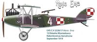
LVG C.V 2228/17 Maria Ema, 12 Eskadra Wywiadowcz Kakenkowicze Aerodrome, September 1919
-

J.Herris - LVG Aircraft of WWI. Volume 3: Types C.VI-C.XI & Fighters /Centennial Perspective/ (36)
LVG C.V 15917/17, 1st Eskadra Wielkopolska, Przemysl Aerodrome, April 1919
-
J.Herris - LVG Aircraft of WWI. Volume 3: Types C.VI-C.XI & Fighters /Centennial Perspective/ (36)
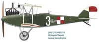
LVG C.V 9495/18 III Repair Depot Lwow Aerodrome
-

A.Olejko - War Wings Over Galicia 1918-1919 /Aeronaut/
LVG C.V in the colors of Ukrainian aviation. Airplanes of this type were also used by Polish aviation, including the 1st Greater Poland Air Squadron - 1919.
-
J.Herris - LVG Aircraft of WWI. Volume 3: Types C.VI-C.XI & Fighters /Centennial Perspective/ (36)
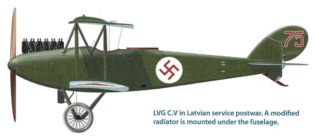
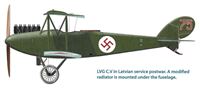
LVG C.V in Latvian service postwar. A modified radiator is mounted under the fuselage.
-
J.Herris - LVG Aircraft of WWI. Volume 3: Types C.VI-C.XI & Fighters /Centennial Perspective/ (36)
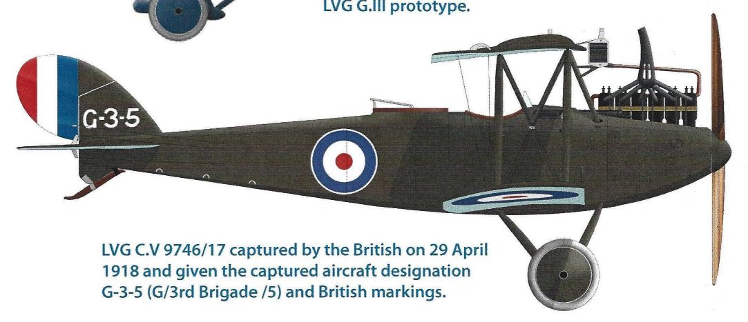
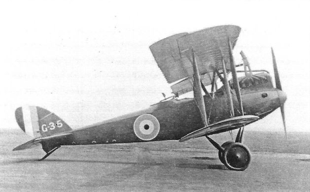
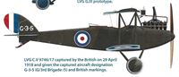
LVG C.V 9746/17 captured by the British on 29 April 1918 and given the captured aircraft designation G-3-5 (G/3rd Brigade /5) and British markings.
-

J.Herris - LVG Aircraft of WWI. Volume 2: Types C.II-C.V /Centennial Perspective/ (35)
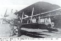
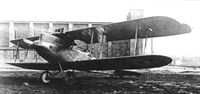
This LVG C.V at Johannisthal was the C.V prototype. The LVG C.V was basically a refinement of the DFW C.V as both were designed by the same man, Diplom-lngenieur Wilhelm Sabersky-Mussigbrodt. Sabersky replaced a very ill Franz Schneider as chief designer at LVG on 1 July 1916, and this was his first design for LVG. (Peter M. Grosz Collection/SDTB)
-
-

J.Herris - LVG Aircraft of WWI. Volume 2: Types C.II-C.V /Centennial Perspective/ (35)
Another view of the LVG C.V prototype at Johannisthal. The LVG C.V was more refined than the preceding DFW C.V and as a result had slightly improved performance. (Peter M. Grosz Collection/SDTB)
-
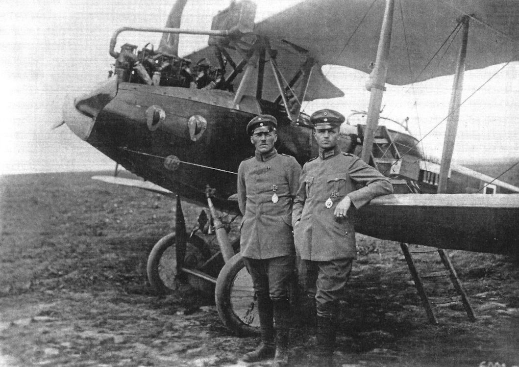
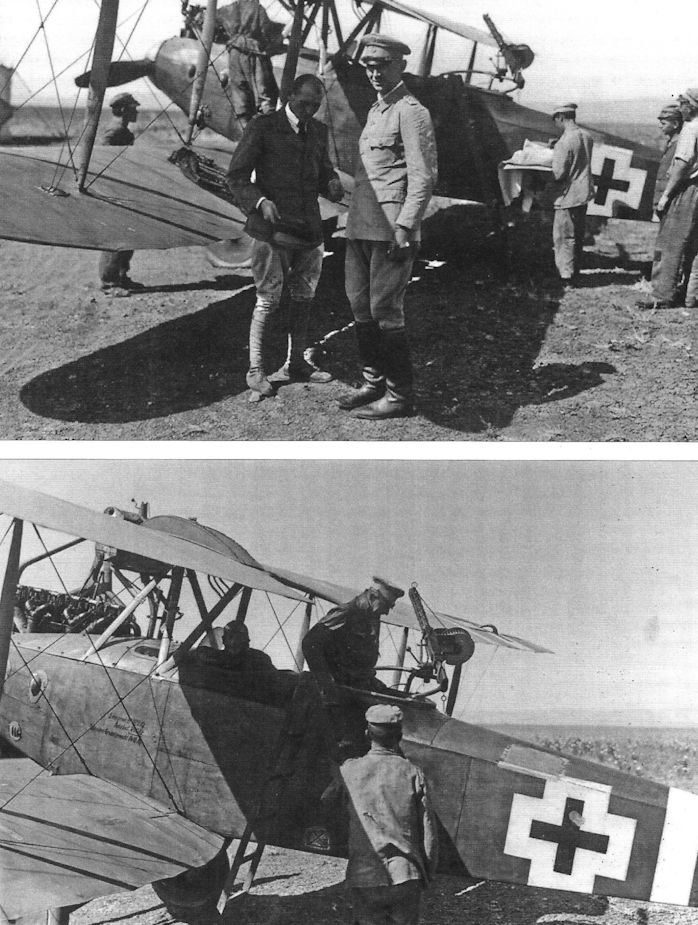
Сайт - Pilots-and-planes /WWW/
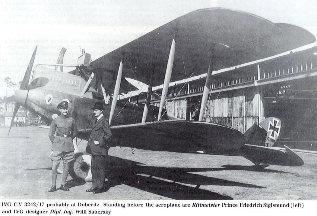
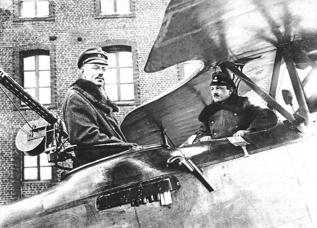
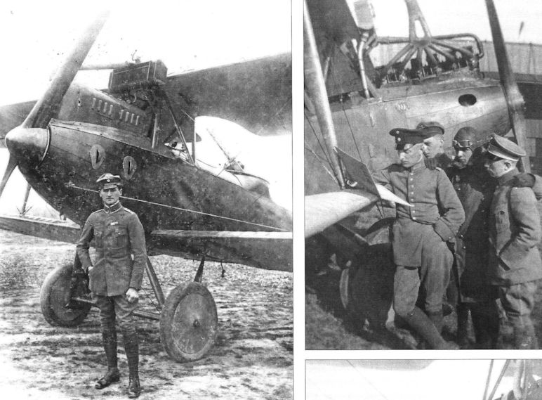
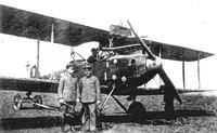
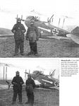
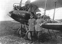
LVG C.V 3242/17 probably at Doberitz. Standing before the aeroplane are Rittmeister Prince Friedrich Sigismund (left) and LVG designer Dipl. Ing. Willi Sabersky
-

J.Herris - LVG Aircraft of WWI. Volume 2: Types C.II-C.V /Centennial Perspective/ (35)
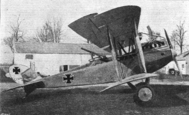
LVG C.V 3263/17 with a neatly applied hammer marking. The upper cowling has been removed for operation in warm weather and it has the usual LVG gun ring and flare holder. The personnel and unit are unidentified.
LVG C.V 3263/17 of Fl. Abt. A 226 in 1917. -
J.Herris - Development of German Warplanes in WWI /Centennial Perspective/ (1)
Tired of paying royalties on the DFW C.V it was building under license, LVG hired the DFW's designer and the LVG C.V was a refinement of the earlier DFW C.V Both aircraft were powered by the 200 hp Benz Bz.IV engine. The LVG C.V served together with the DFW C.V in two-seater units until the end of the war.
LVG C.V 3272/17 of the first production batch. The interplane and undercarriage struts are wood to conserve steel tube. -
Сайт - Pilots-and-planes /WWW/
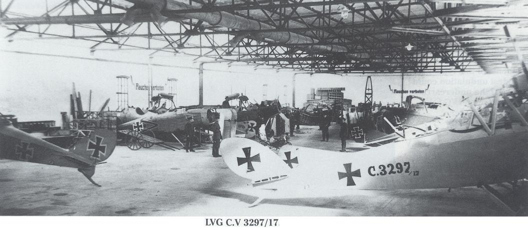
LVG C.V 3297/17
-
J.Herris - LVG Aircraft of WWI. Volume 2: Types C.II-C.V /Centennial Perspective/ (35)
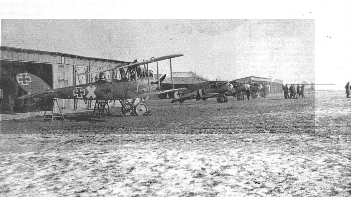
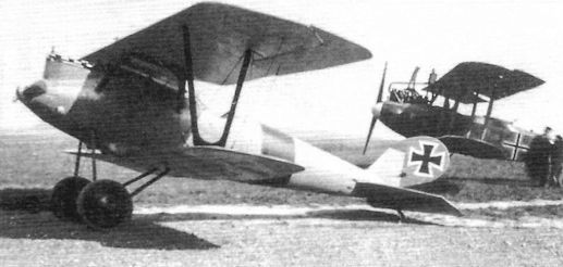
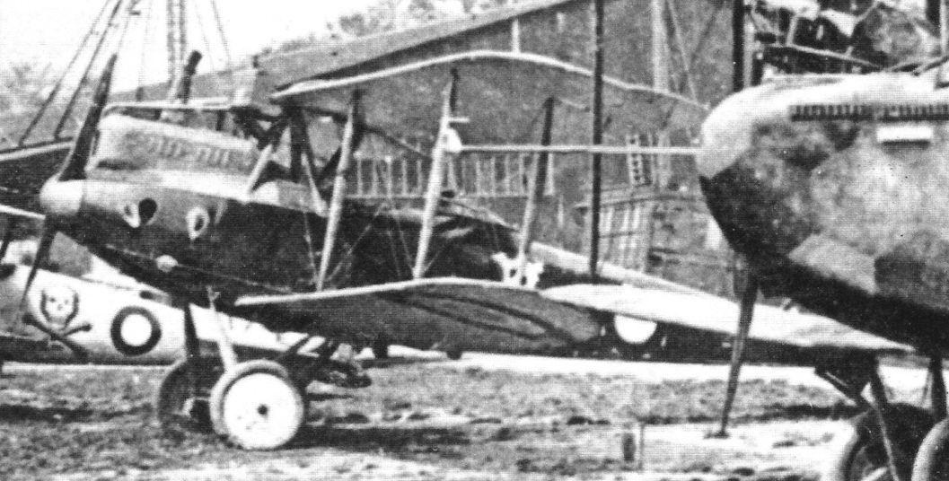
LVG C.V 3314/17 shares the field with some Albatros D.Va fighters. The 'X' marking on the fuselage is interesting. The serial number still appears on the rudder. (Peter M. Grosz Collection/SDTB)
Другие самолёты на фотографии: Albatros D.V/D.Va - Германия - 1917
-
J.Herris - LVG Aircraft of WWI. Volume 2: Types C.II-C.V /Centennial Perspective/ (35)
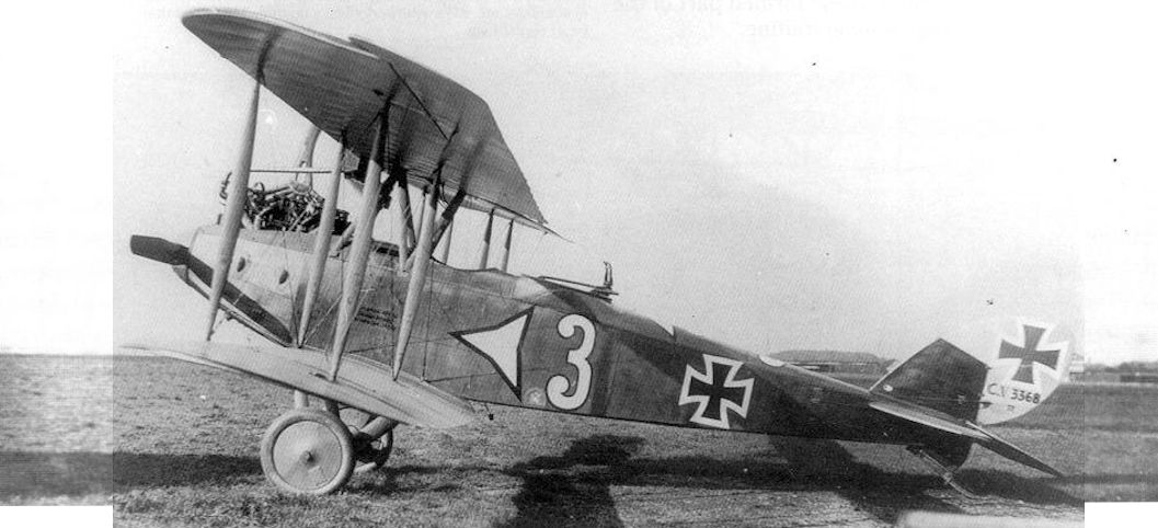
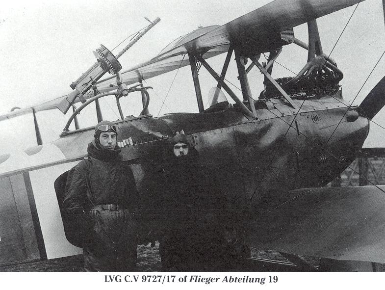
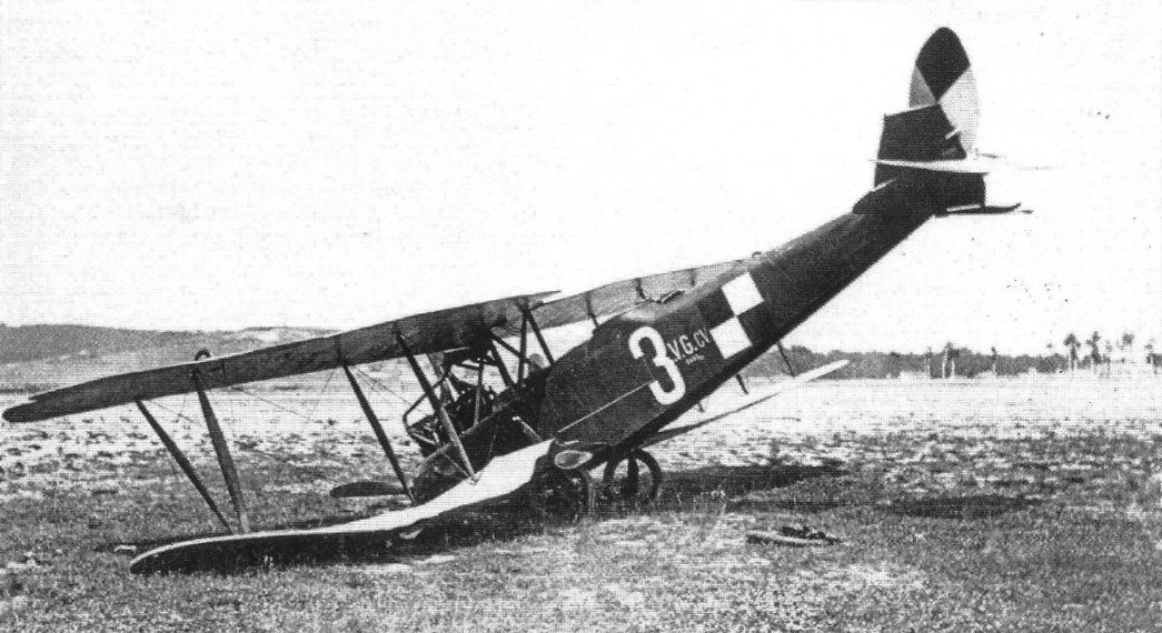
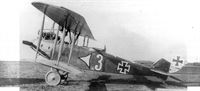
LVG C.V 3368/17 carries tactical no. 3 and a Mercedes Star on the fuselage, which was the unit marking of Fl. Abt. 19. The production center-section offered a good field of view and fire. (Peter M. Grosz Collection/SDTB)
-
Сайт - Pilots-and-planes /WWW/
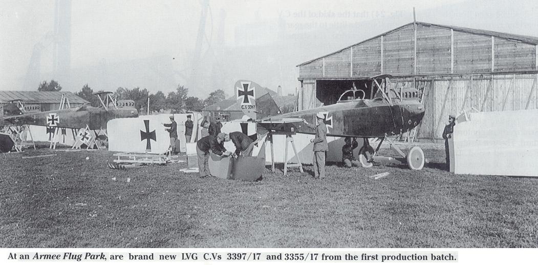
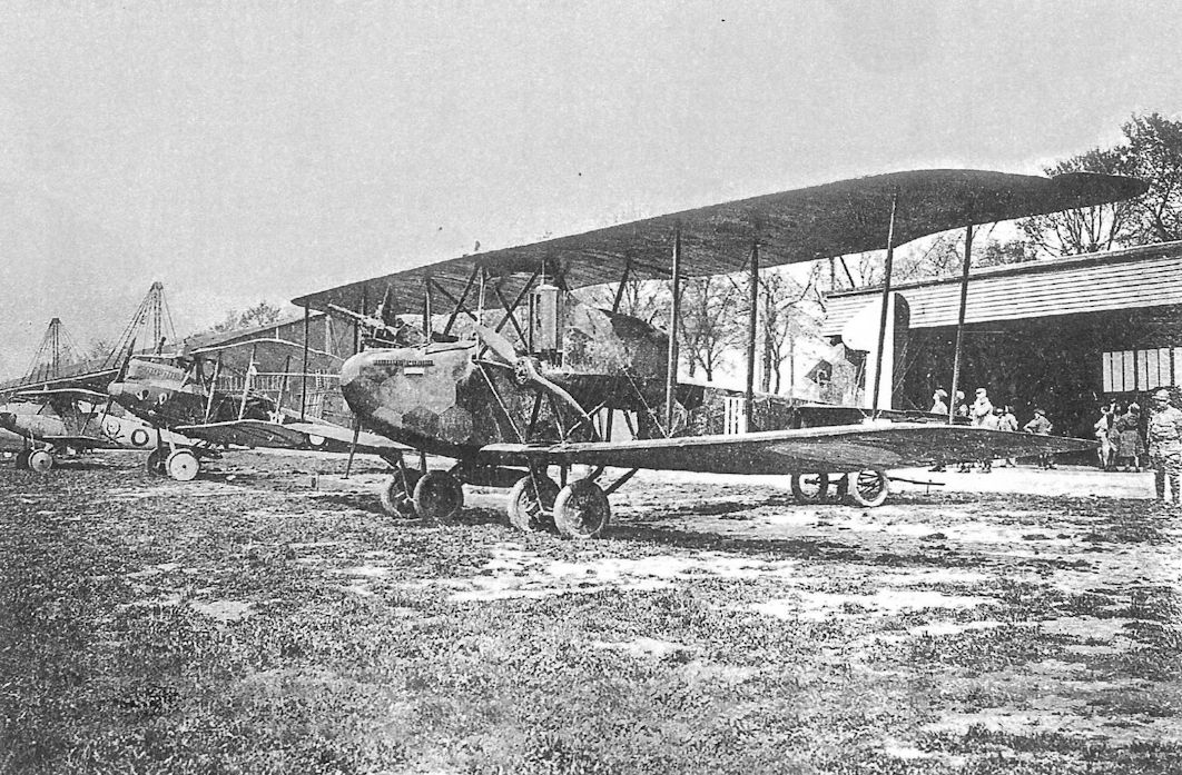
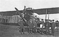
At an Armee Flug Park, are brand new LVG C.Vs 3397/17 and 3355/17 from the first production batch.
-
J.Herris - LVG Aircraft of WWI. Volume 2: Types C.II-C.V /Centennial Perspective/ (35)
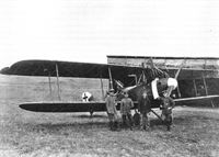
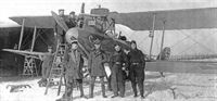
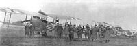
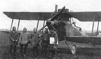
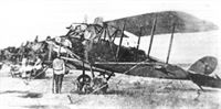
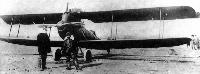
LVG C.V 3882/17 with its ground crew on its airfield. (Greg VanWyngarden)
-
J.Herris - LVG Aircraft of WWI. Volume 2: Types C.II-C.V /Centennial Perspective/ (35)
LVG C.V, likely 3882/17, running up its engine, apparently prior to a mission. (Greg VanWyngarden)
-
J.Herris - LVG Aircraft of WWI. Volume 2: Types C.II-C.V /Centennial Perspective/ (35)
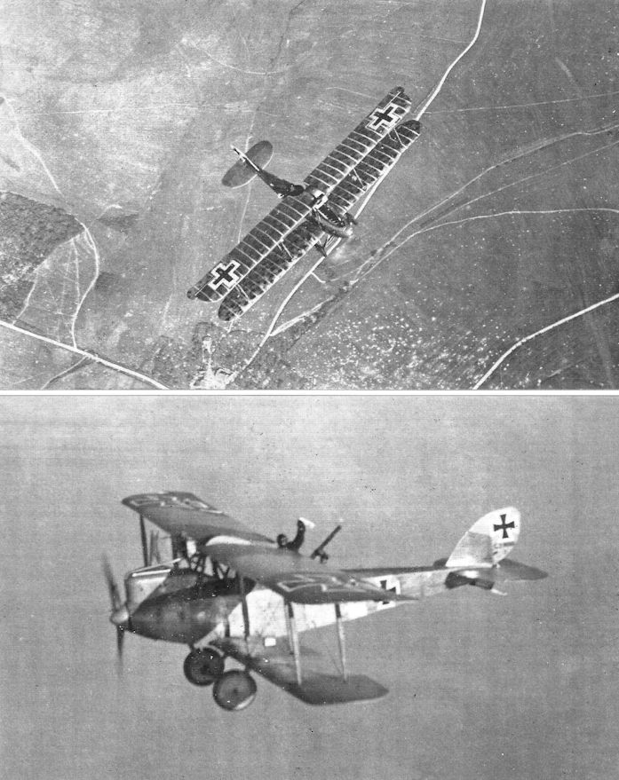
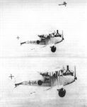
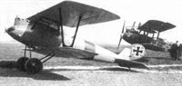
LVG C.V 4404/17 photographed in flight. We can not explain the large application of the serial number on the fuselage and the overall light paint job; this would often indicate a training or communications machine, but this one is armed and 'escorted'; the upper photo shows its Fokker D.VII escort. A long streamer is attached to the outboard wing strut. The exhaust manifold is somewhat different shape than that normally seen.
Другие самолёты на фотографии: Fokker D.VII / V11 / V18 / V22 / V24 - Германия - 1917
-

J.Herris - LVG Aircraft of WWI. Volume 2: Types C.II-C.V /Centennial Perspective/ (35)
Official Kogenluft photo of LVG C.V 9154/17 loading mail at Keiv. This machine is disarmed - no pilot's gun and no Parabellum. The translucency of the wings would indicate that they were covered in clear-doped linen and not camouflaged, in keeping with its non-combat role.
-

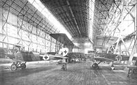
J.Herris - LVG Aircraft of WWI. Volume 2: Types C.II-C.V /Centennial Perspective/ (35)
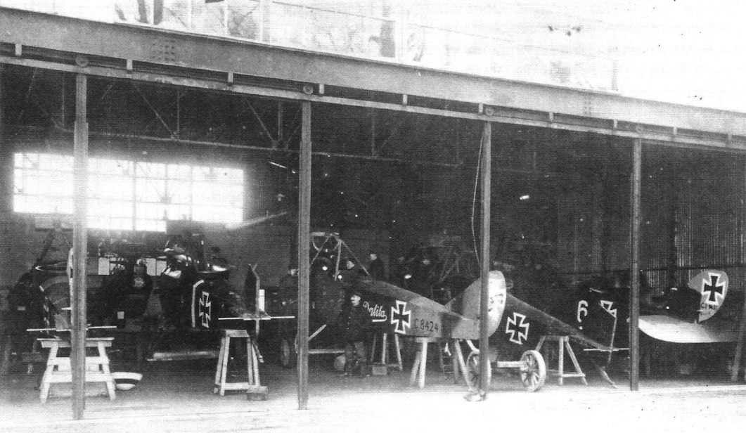
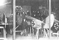
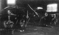
LVG C.V 9437/17 (at right) and Rumpler C.IV C8424/16 Dalila are among the aircraft being repaired in this hangar. Two more LVG C.V aircraft are visible along with another aircraft, perhaps an LVG C.V, at left. The photo was taken at AFP 4.
Другие самолёты на фотографии: Rumpler C.IV - Германия - 1916
-
J.Herris - LVG Aircraft of WWI. Volume 2: Types C.II-C.V /Centennial Perspective/ (35)
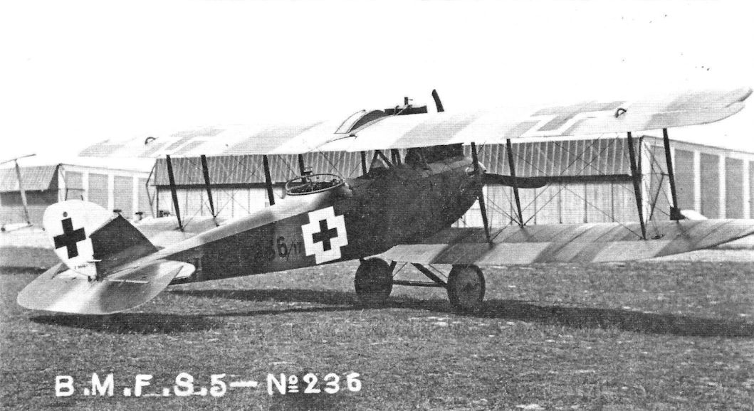
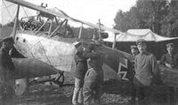
The previous markings have apparently been scrapped off LVG C.V 9474/17 and it is being used as a "hack" aircraft by Jasta 5. The original white band and "6" show through a coat of overpaint, possibly in Jasta 5 green. The engine is running and the aircraft is ready for take-off. The upper cowling has been removed to prevent overheating in warm weather.
-

J.Herris - LVG Aircraft of WWI. Volume 2: Types C.II-C.V /Centennial Perspective/ (35)
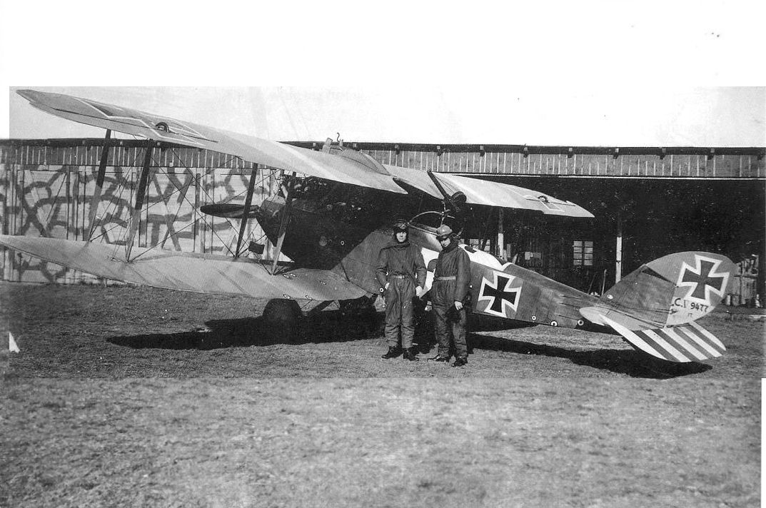
View of LVG C.V 9477/17 of FA(A) 238 at Ingelmunster. At least 14 bullet holes are covered by patches painted as cockades. The aircraft carries a barograph between the inner wing struts. (Peter M. Grosz Collection/SDTB)
-
J.Herris - LVG Aircraft of WWI. Volume 2: Types C.II-C.V /Centennial Perspective/ (35)
LVG C.V 9563/17 with its ground crew on its airfield. (Greg VanWyngarden)
-
J.Herris - LVG Aircraft of WWI. Volume 2: Types C.II-C.V /Centennial Perspective/ (35)
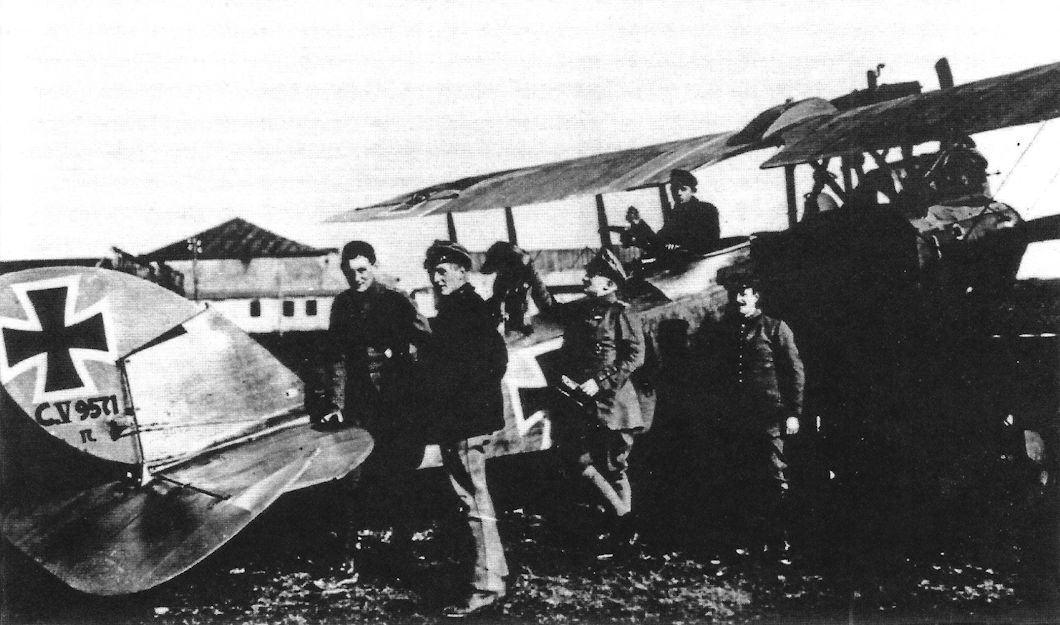
Unit personnel have their photo taken with LVG C.V 9571/17.
-
J.Herris - LVG Aircraft of WWI. Volume 2: Types C.II-C.V /Centennial Perspective/ (35)
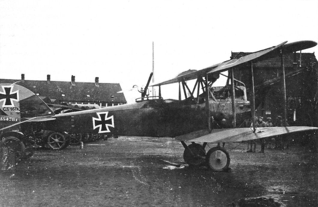
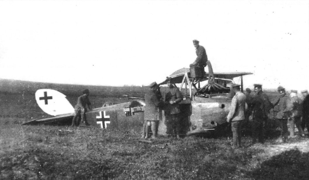
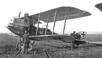
Captured LVG C.V 9574/17. (Greg VanWyngarden)
-
Сайт - Pilots-and-planes /WWW/
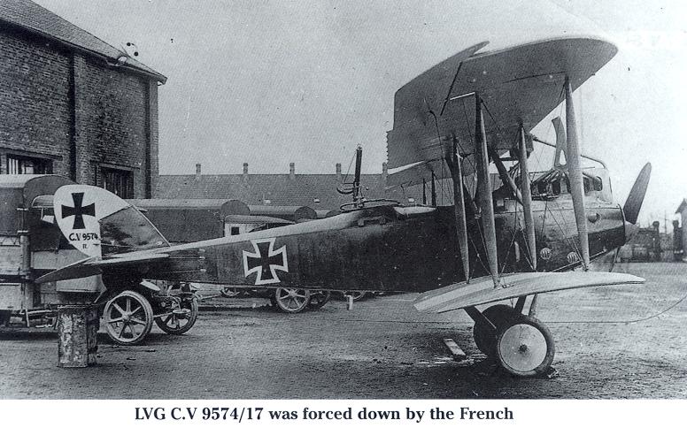
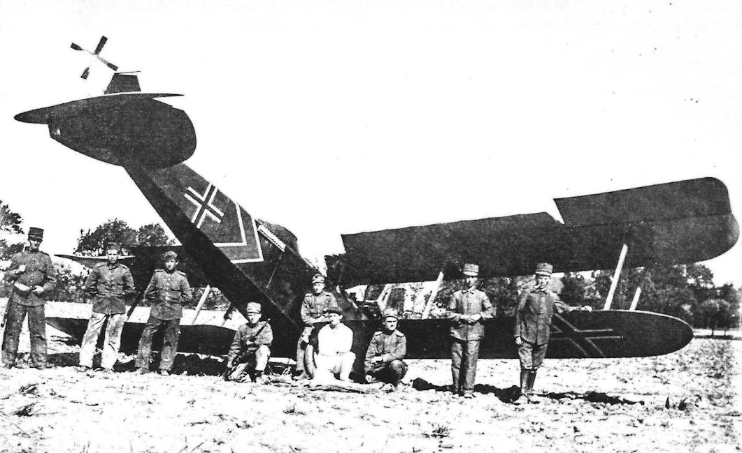
LVG C.V 9574/17 was forced down by the French
-
Сайт - Pilots-and-planes /WWW/
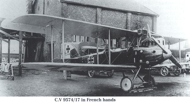
LVG C.V 9574/17 in French hands
-
J.Herris - LVG Aircraft of WWI. Volume 2: Types C.II-C.V /Centennial Perspective/ (35)
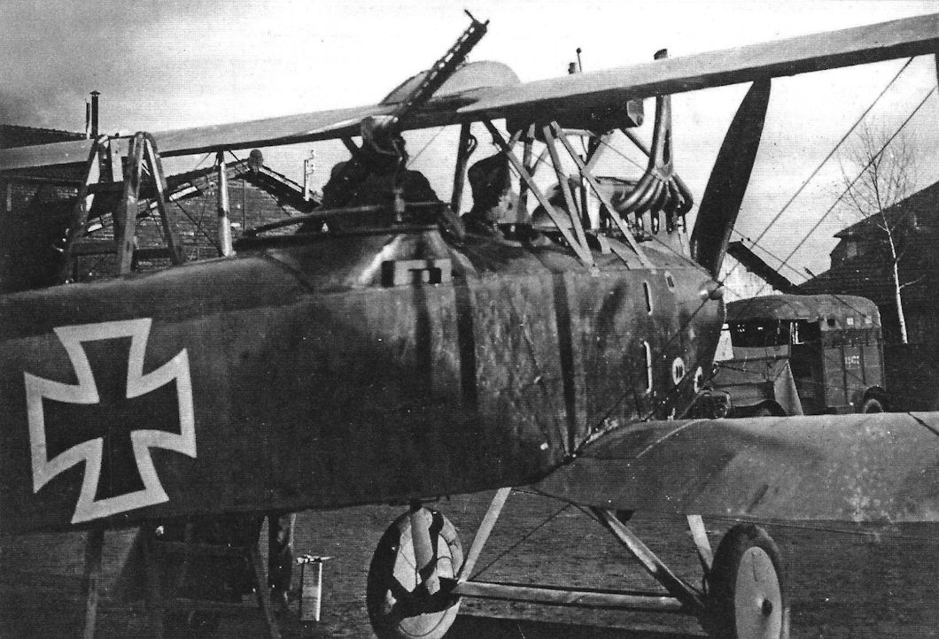
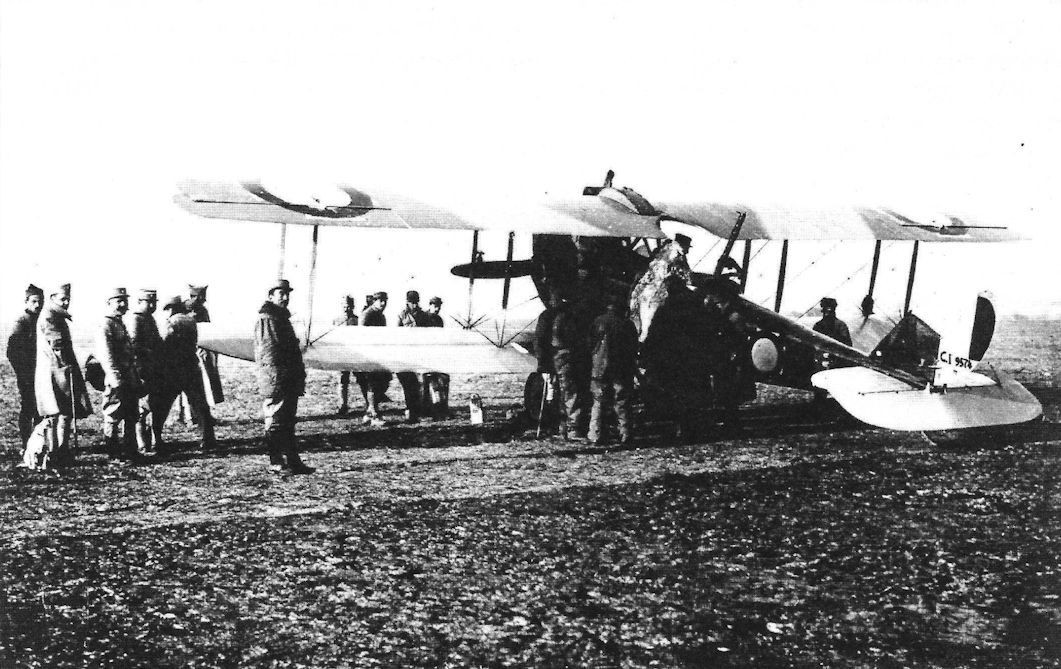
LVG C.V 9574/17 was captured on 27 November, 1917. It was assigned to FA(A) 258 and is shown during its evaluation by the French. (Greg VanWyngarden)
-
J.Herris - LVG Aircraft of WWI. Volume 2: Types C.II-C.V /Centennial Perspective/ (35)
LVG C.V 9574/17 was captured on 27 November, 1917. It was assigned to FA(A) 258 and is shown during its evaluation by the French. (Greg VanWyngarden)
-

J.Herris - LVG Aircraft of WWI. Volume 2: Types C.II-C.V /Centennial Perspective/ (35)
LVG C.V 9574/17 was captured at Auroir. It was assigned to FA(A) 258; Lt. Hans Schrock, observer, was made POW. Here a French crew is in the aircraft. (Greg VanWyngarden)
-
J.Herris - LVG Aircraft of WWI. Volume 2: Types C.II-C.V /Centennial Perspective/ (35)
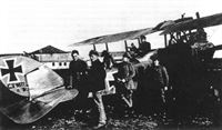
LVG C.V 9574/17 after capture surrounded by French mechanics. (Greg VanWyngarden)
-

J.Herris - LVG Aircraft of WWI. Volume 2: Types C.II-C.V /Centennial Perspective/ (35)
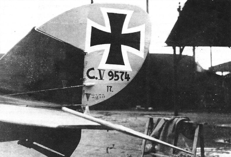
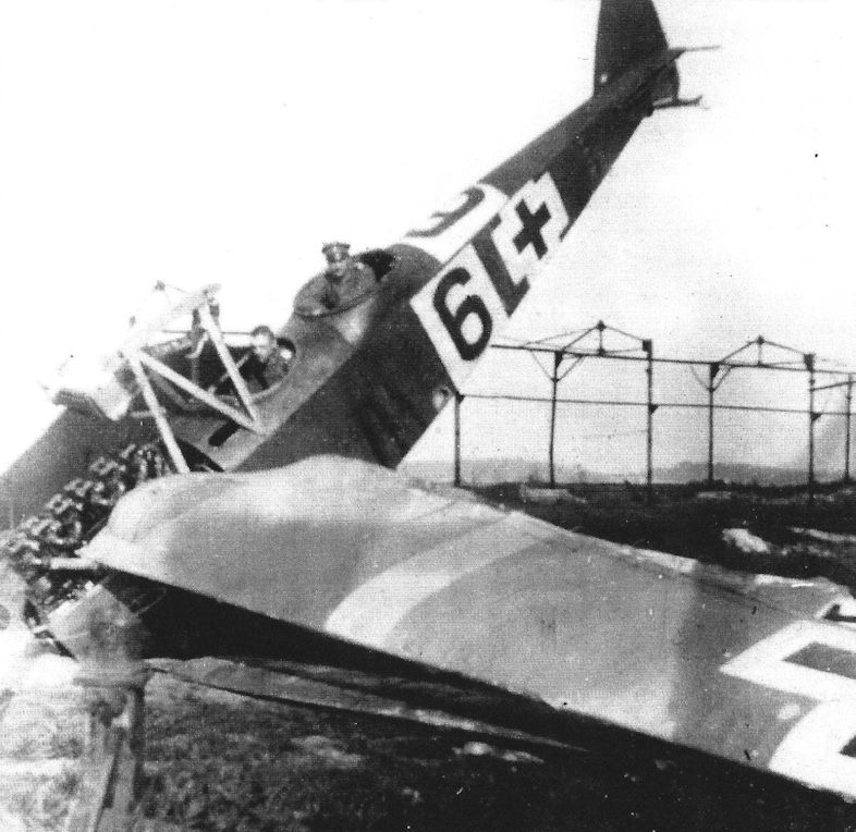
Close-up of the tail of LVG C.V 9574/17 after capture. (Greg VanWyngarden)
-

M.Dusing - German & Austro-Hungarian Aero Engines of WWI. Vol.1 /Centennial Perspective/ (64)
LVG C.V with Bz IV 225 hp engine. [1918]
-

J.Herris - LVG Aircraft of WWI. Volume 2: Types C.II-C.V /Centennial Perspective/ (35)
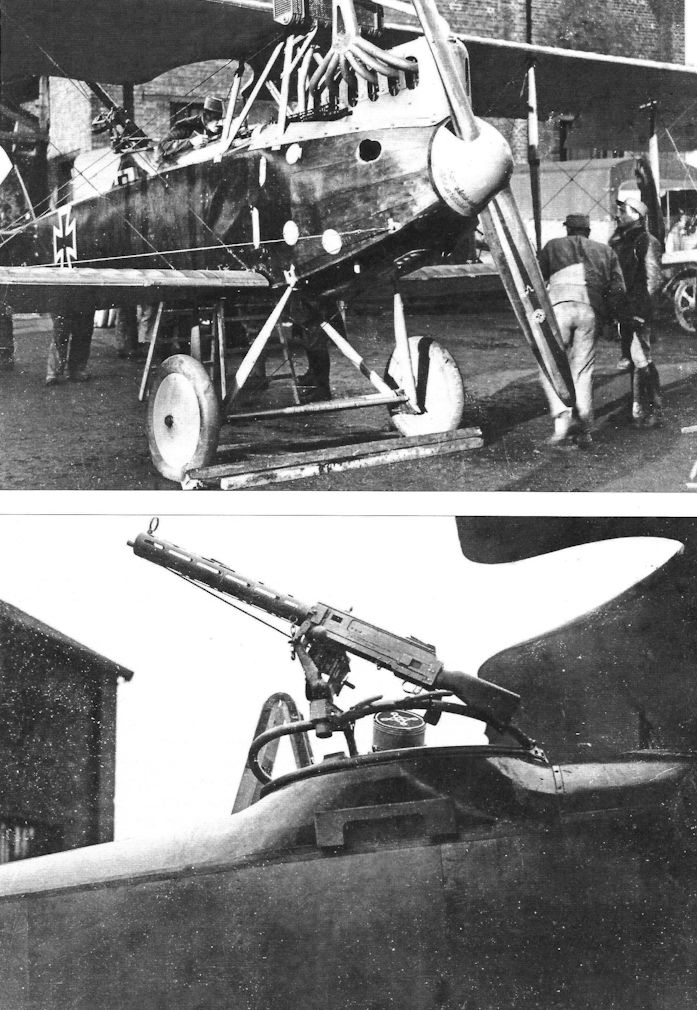
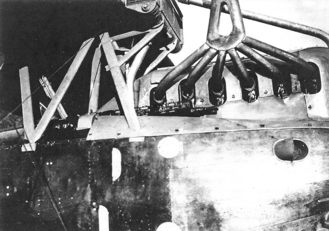
Nose detail of LVG C.V 9574/17 after its capture during its evaluation by the French. (Greg VanWyngarden)
-
J.Herris - LVG Aircraft of WWI. Volume 2: Types C.II-C.V /Centennial Perspective/ (35)
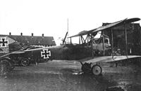
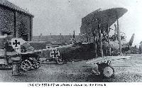
Captured LVG C.V 9574/17 being inspected by French officers after being painted in French insignia. (Greg VanWyngarden)
-
J.Herris - LVG Aircraft of WWI. Volume 2: Types C.II-C.V /Centennial Perspective/ (35)
LVG C.V 9574/17 photographed at Cantigny 6 December, 1917. It is being evaluated after capture by the French and has been painted in French national insignia. (Greg VanWyngarden)
-
J.Herris - LVG Aircraft of WWI. Volume 2: Types C.II-C.V /Centennial Perspective/ (35)
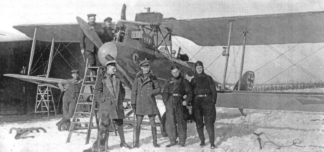
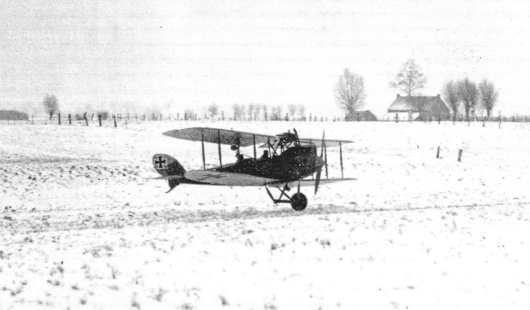
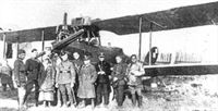
LVG C.V 9637/17 ready for take-off on its next mission in the winter snow. (Greg VanWyngarden)
-

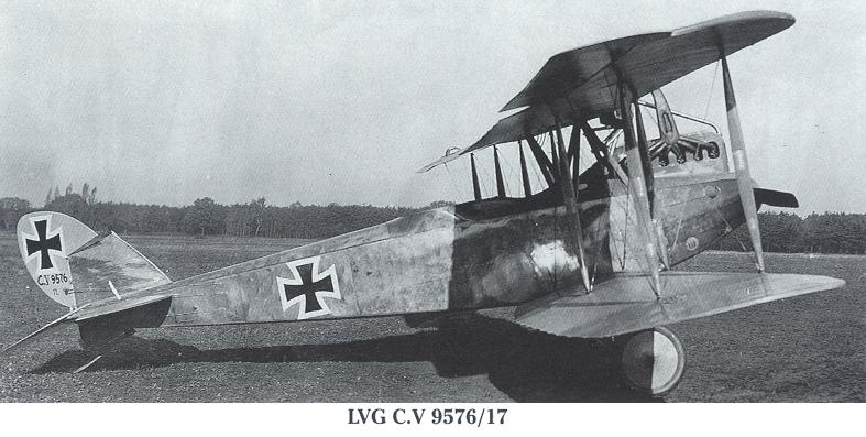
Сайт - Pilots-and-planes /WWW/
LVG C.V 9576/17
-
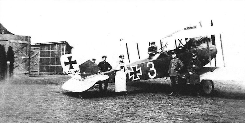
J.Herris - LVG Aircraft of WWI. Volume 2: Types C.II-C.V /Centennial Perspective/ (35)
LVG C.V 9663/17 tactical number 3. (Greg VanWyngarden)
-

Z.Czirok - German Aircraft in Hungarian Service /Centennial Perspective/ (92)
A postwar view of LVG C.V 9667/17 taken in April 1919. The large, non-standard presentation of the serial number indicates this aircraft may have been flown as a trainer.
LVG C.V 9667/17 on the Kiev airfield. Russian pilot Victor Hodorovich arrived in Matyasfold with this plane on 15th April 1919. -

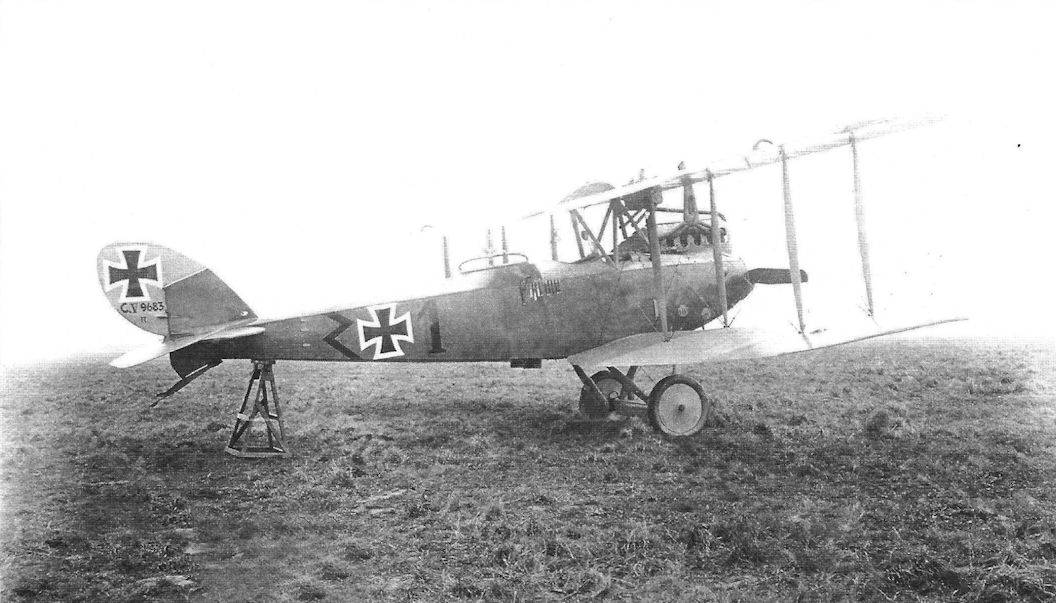
J.Herris - LVG Aircraft of WWI. Volume 2: Types C.II-C.V /Centennial Perspective/ (35)
LVG C.V 9683/17 of FA 210. There is a zig-zag marking on the rear fuselage and tactical number 1 .The observer has an LVG gun ring and a rack of flares on the side of the observer's cockpit.
-
J.Herris - LVG Aircraft of WWI. Volume 2: Types C.II-C.V /Centennial Perspective/ (35)
LVG C.V 9699/17 on wheel Type I Zak III painted white. (Greg VanWyngarden)
-

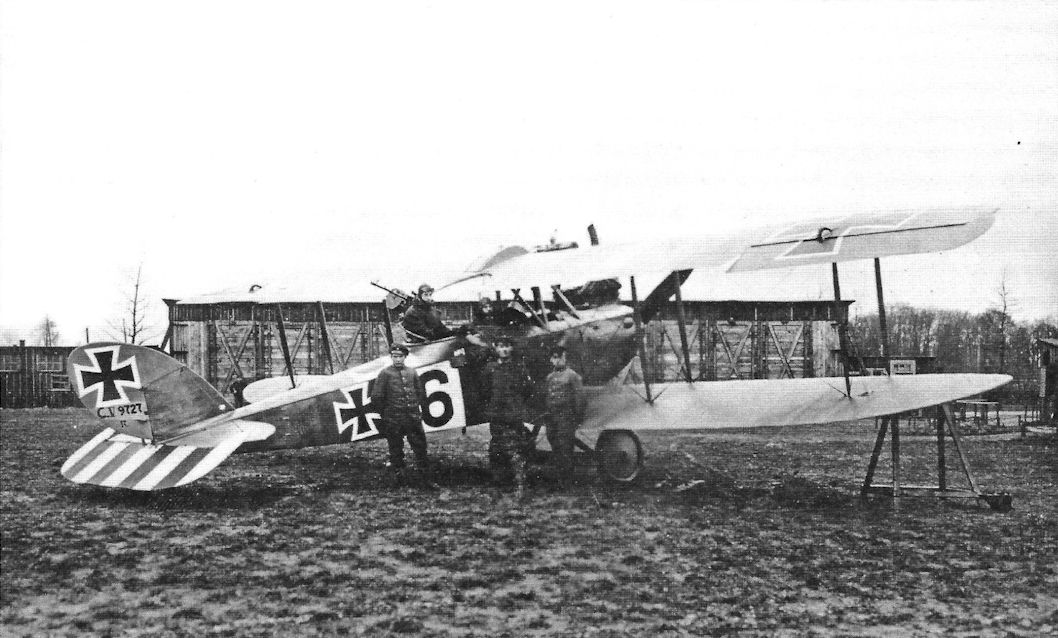
J.Herris - LVG Aircraft of WWI. Volume 2: Types C.II-C.V /Centennial Perspective/ (35)
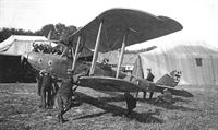
LVG C.V 9727/17 in the colorful markings of FliegerAbteilung (A) 238. A field modification to strengthen the tail was the cable between the fin and horizontal stabilizer. The LVG gun mount was a copy of the British Scarff ring. (Peter M. Grosz Collection/SDTB)
-
Сайт - Pilots-and-planes /WWW/
LVG C.V 9727/17 of Flieger Abteilung 19
-
J.Herris - LVG Aircraft of WWI. Volume 2: Types C.II-C.V /Centennial Perspective/ (35)
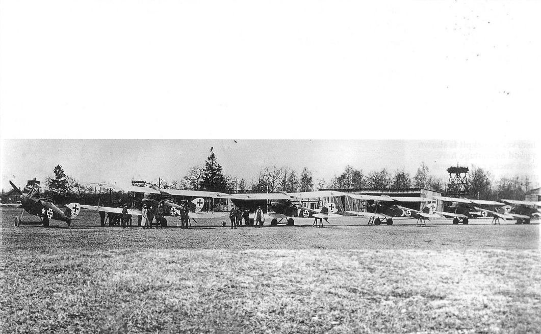
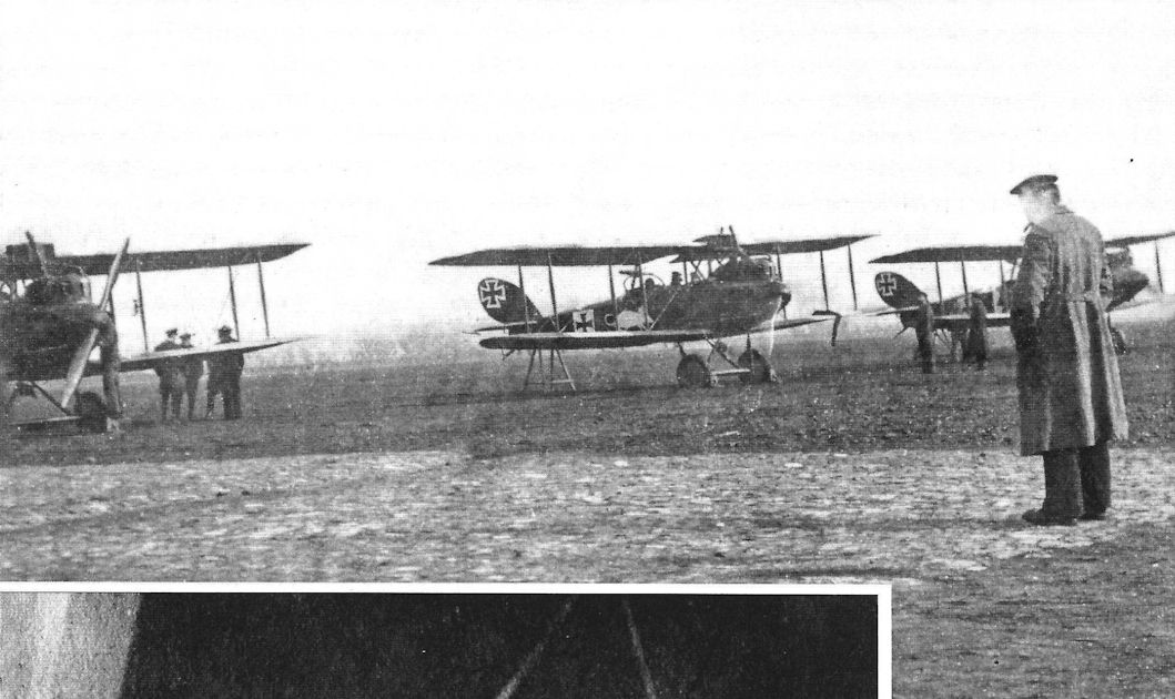
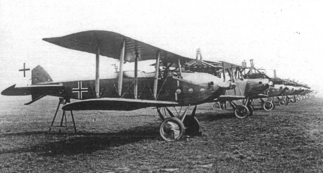
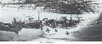
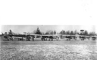
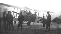
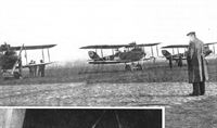
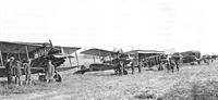
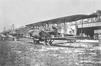
Six LVG C.V biplanes, including C.9730/17, C.14595/17 and C.14603/17
Unit lineup of LVG C.V aircraft of Fl. Abt. (A) 255 in the summer of 1917. Each aircraft appears to have an individual fuselage marking (star on the left aircraft, band, crescent, and arrow are visible). (Peter M. Grosz Collection/SDTB) -

J.Herris - LVG Aircraft of WWI. Volume 2: Types C.II-C.V /Centennial Perspective/ (35)
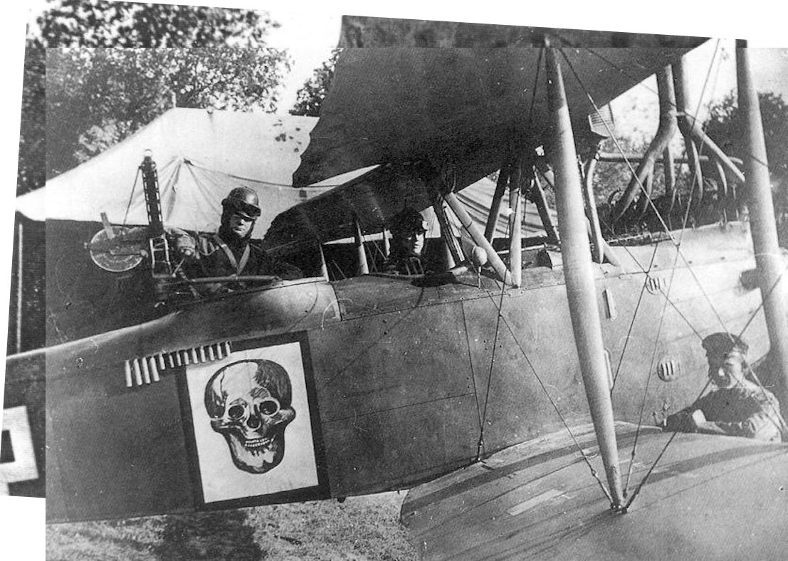
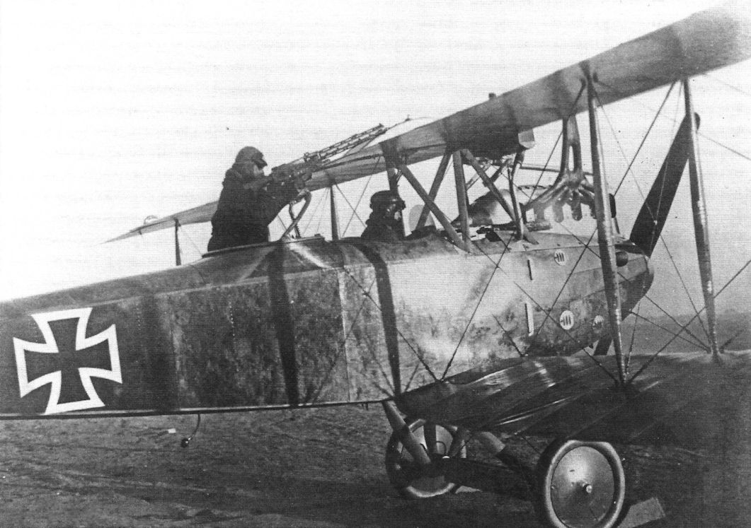
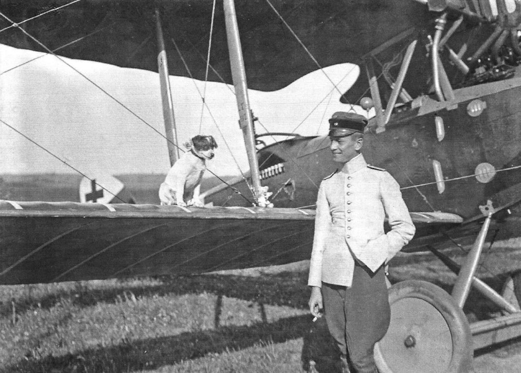
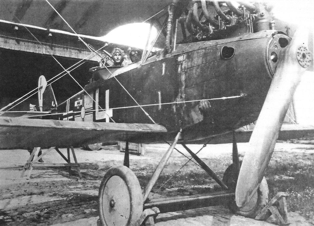
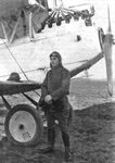
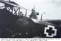
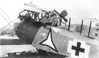
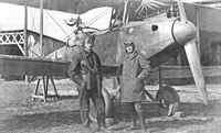
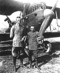
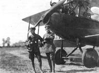
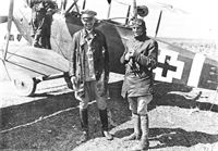
Lt. Willi Pysall of FliegerAbteilung (A) 212 in the observer's cockpit of LVG C.V 9751/17 with his pilot ready for takeoff. The rack above the skull insignia is full of flares for the mission.
-
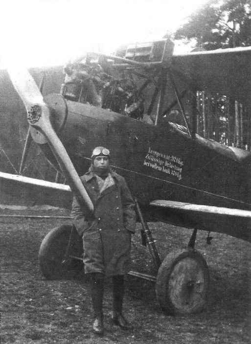
Сайт - Pilots-and-planes /WWW/
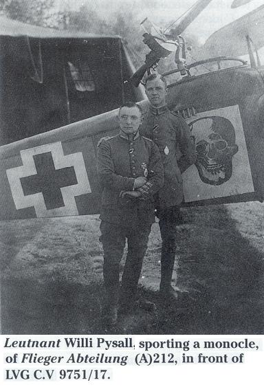
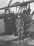
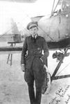
Leutnant Willi Pysall sporting a monocle, of Flieger Abteilung (A) 212, in front of LVG C.V 9751/17.
-
Сайт - Pilots-and-planes /WWW/
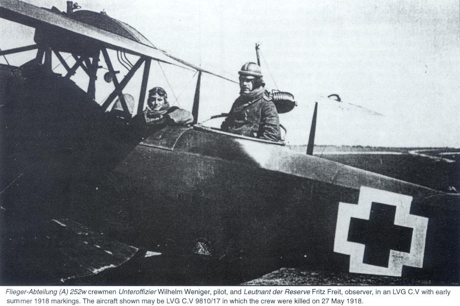
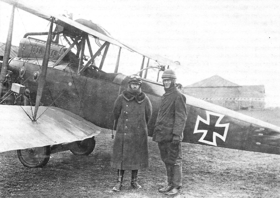
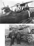
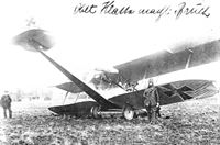
Flieger-Abteilung (A) 252w crewmen Unteroffizier Wilhelm Weniger, pilot, and Leutnant der Reserve Fritz Freit, observer, in an LVG C.V with early summer 1918 markings. The aircraft shown may be LVG C.V 9810/17 in wich the crew were killed on 27 May 1918.
-
Сайт - Pilots-and-planes /WWW/
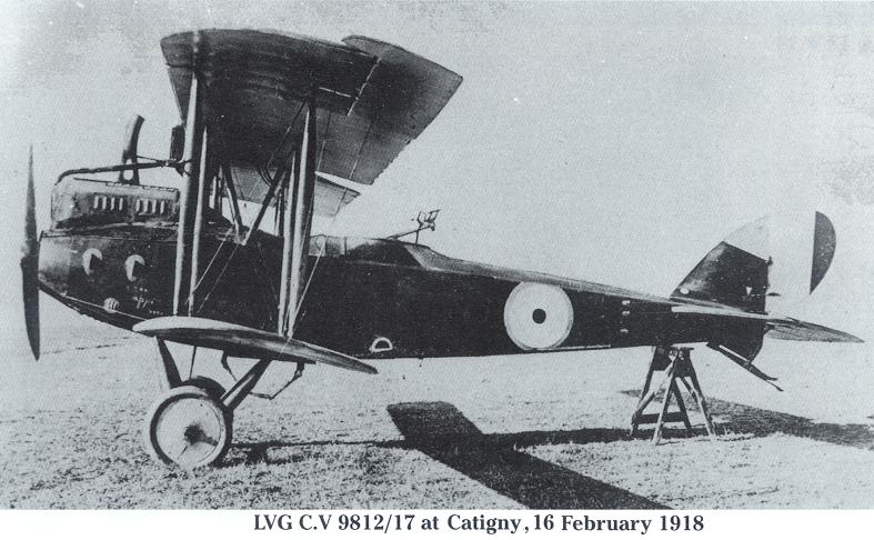
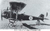
LVG C.V 9812/17 at Catigny, 16 February 1918
-
J.Herris - LVG Aircraft of WWI. Volume 2: Types C.II-C.V /Centennial Perspective/ (35)
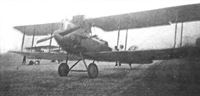
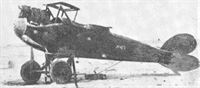
LVG C.V 9812/17. It has the full cowling used in cold weather.
-

H.Cowin - Aviation Pioneers /Osprey/
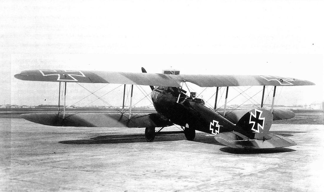
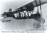
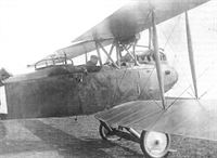
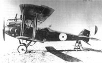
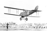
This LVG C V two seater has been flown to England for test and evaluation after its capture. First flown in early 1917, the LVG C V was deployed operationally during the summer of 1917. A sturdy design, the machine was well liked by its crews despite the somewhat restricted visibility it offered to both pilot and observer. Powered by a 200hp Benz Bz IV, the CV had a top level speed of 105mph at sea level, along with an impressive ceiling of 21,060 feet. Pilot and observer both had a 7.92mm machine gun. While no precise figures survive, several hundred LVG C Vs are known to have been built.
-
J.Herris - LVG Aircraft of WWI. Volume 2: Types C.II-C.V /Centennial Perspective/ (35)
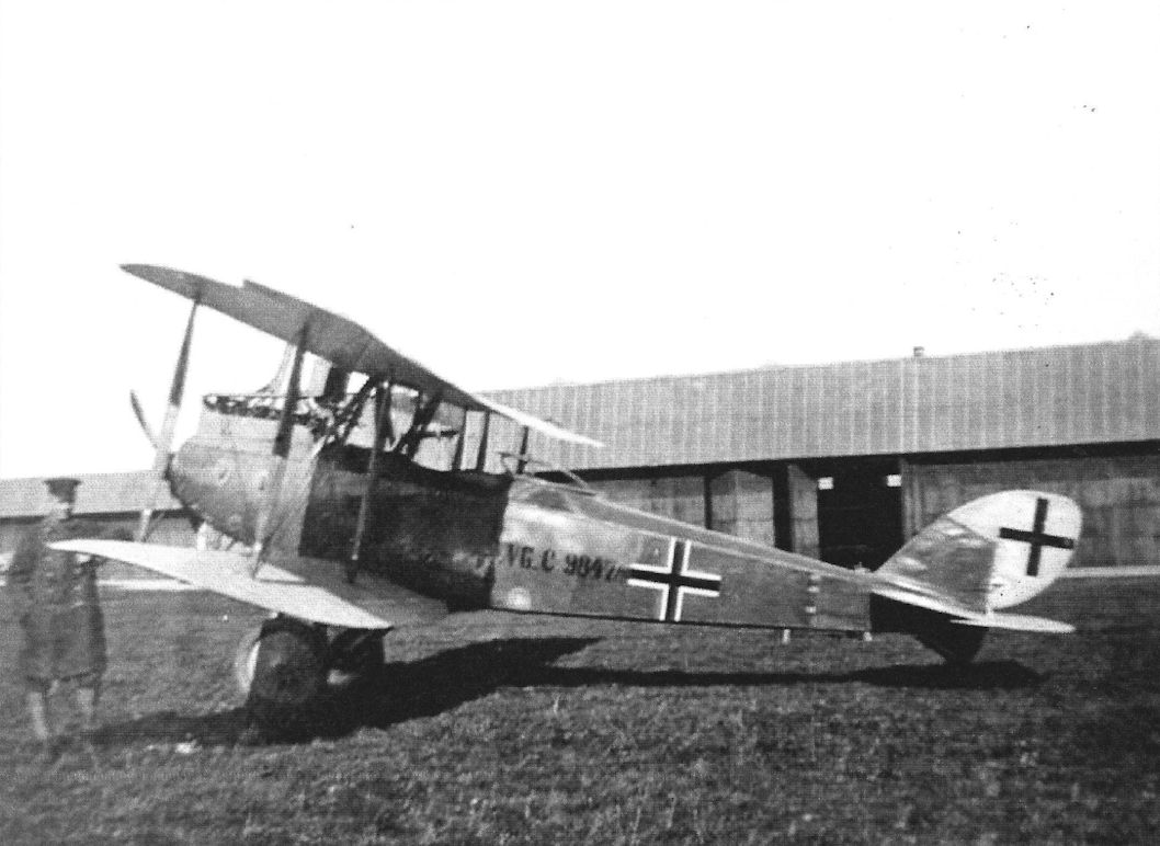
LVG C.V, 9847/17 in Schwerin in August 1918; note the unusual re-application of the serial. (Greg VanWyngarden)
-
J.Herris - LVG Aircraft of WWI. Volume 2: Types C.II-C.V /Centennial Perspective/ (35)
LVG C.V 9889/17 of FA 210 has a horseshoe fuselage marking, perhaps the unit marking. A Bavarian (?) Lion marking is on the fin, shown in close-up at left. The lion insignia on the fin may not be the Bavarian version (it doesn't have the double tail of the Bavarian Lion), but it seems to be holding an emblem of a bomb or a grenade. Furthermore, underneath it is the Latin proverb Carpe Diem (seize the day). Interestingly, the rudder has a 1918 cross but the rest of the aircraft carries the standard as-built 1917 national insignia.
-
J.Herris - LVG Aircraft of WWI. Volume 2: Types C.II-C.V /Centennial Perspective/ (35)
LVG C.V 9895/17. (Greg VanWyngarden)
-
J.Herris - LVG Aircraft of WWI. Volume 2: Types C.II-C.V /Centennial Perspective/ (35)
LVG C.V 13484/17 work number 3802.
-

J.Herris - LVG Aircraft of WWI. Volume 2: Types C.II-C.V /Centennial Perspective/ (35)
LVG C.V 14412/17 of an unknown unit is painted a light color. It has a Man-in-the-moon marking on the fuselage and a mascot/good luck charm on an inboard inter-plane strut. (Greg VanWyngarden)
-

J.Herris - LVG Aircraft of WWI. Volume 2: Types C.II-C.V /Centennial Perspective/ (35)
Derelict LVG C.V in a hangar. The presence of an American soldier indicates the time is postwar. The aircraft sports a crescent Moon fuselage marking.
-

J.Herris - LVG Aircraft of WWI. Volume 2: Types C.II-C.V /Centennial Perspective/ (35)
LVG C.V 14443/17 photographed with ground crew has been dismantled for transportation. (Piotr Mrozowski)
-
J.Herris - LVG Aircraft of WWI. Volume 2: Types C.II-C.V /Centennial Perspective/ (35)
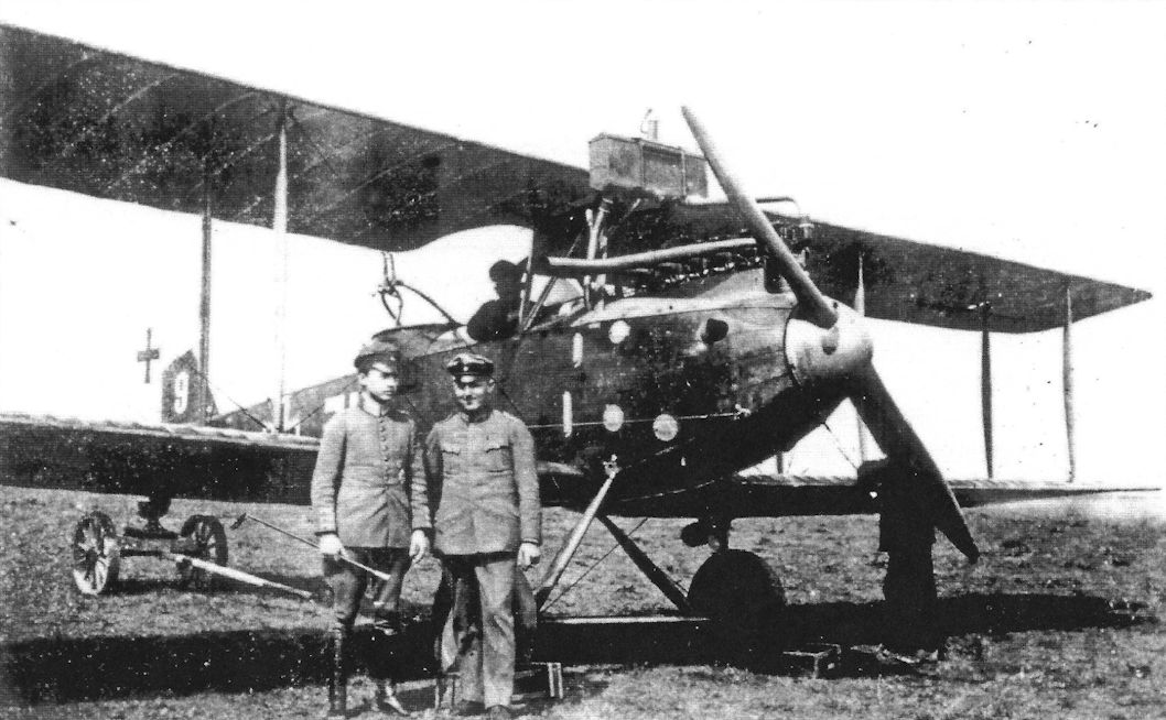
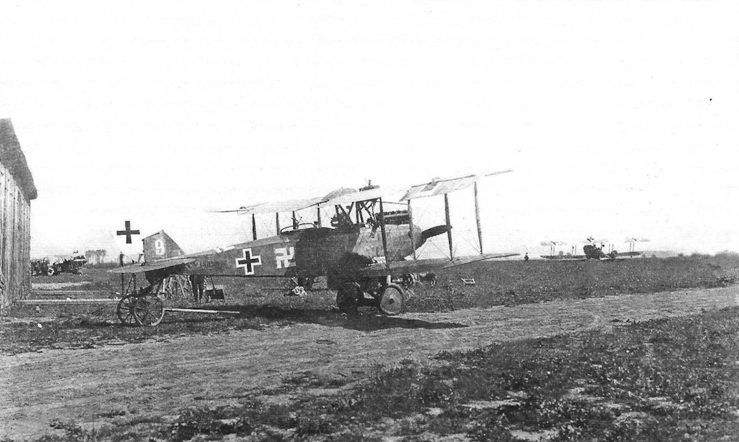
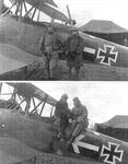
LVG C.V (possibly 15820/17) of Saxon FA(A) 208 tactical no. 9; Lt. Dannenberg, observer, pilot Andres or Andresen. (Greg VanWyngarden)
-

J.Herris - LVG Aircraft of WWI. Volume 2: Types C.II-C.V /Centennial Perspective/ (35)
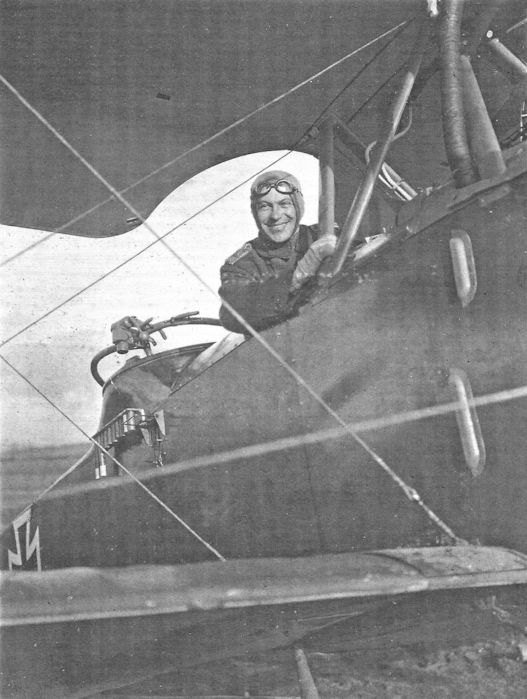
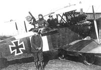
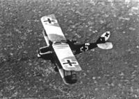
LVG C.V (possibly 15820/17) of Saxon FA(A) 208 tactical no. 9; the swastika is the unit marking. (Greg VanWyngarden)
-

J.Herris - LVG Aircraft of WWI. Volume 2: Types C.II-C.V /Centennial Perspective/ (35)
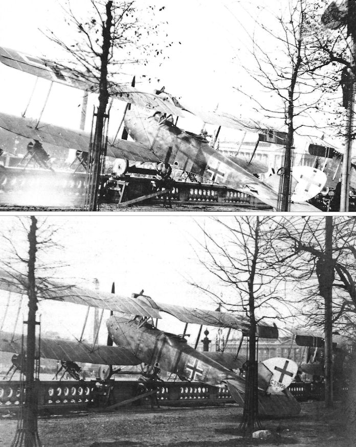
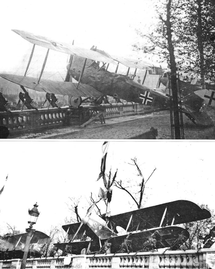
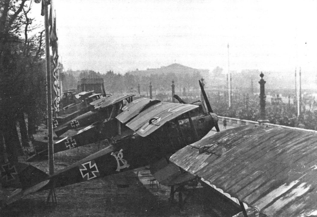
Two views of captured LVG C.V 15950/17 on display at the Tuilleries Gardens in Paris in October/ November 1918. (Greg VanWyngarden)
-
J.Herris - LVG Aircraft of WWI. Volume 2: Types C.II-C.V /Centennial Perspective/ (35)
Two views of captured LVG C.V 15950/17 on display at the Tuilleries Gardens in Paris in October/ November 1918. (Greg VanWyngarden)
-
J.Herris - LVG Aircraft of WWI. Volume 2: Types C.II-C.V /Centennial Perspective/ (35)
LVG C.V 1766/17 (???) in early 1918 insignia. The serial number has been applied to the fuselage, which is now camouflaged, instead of the rudder per previous LVG practice. (Peter M. Grosz Collection/SDTB)
-

J.Herris - LVG Aircraft of WWI. Volume 2: Types C.II-C.V /Centennial Perspective/ (35)
Lt. Wittmann with LVG C.V 1026/18 of FAA 287b in the field. A pennant hangs from the wingtip.
-
J.Herris - LVG Aircraft of WWI. Volume 2: Types C.II-C.V /Centennial Perspective/ (35)
LVG C.V 1766/18 under repair with other aircraft in an airship hangar. As part of the repair job, the fuselage has been repainted in the same two camouflage colors seen on the wings; this was not done at the factory originally. The camouflage pattern on the wings also indicates that they have been repainted. (Peter M. Grosz Collection/SDTB)
-
J.Herris - LVG Aircraft of WWI. Volume 2: Types C.II-C.V /Centennial Perspective/ (35)
LVG C.V 1783/18 ready for take-off. The spinner is not fitted.
-

J.Herris - LVG Aircraft of WWI. Volume 2: Types C.II-C.V /Centennial Perspective/ (35)
Franz und Emil with their LVG C.V 1783/18 that has the serial on the fuselage. The LVG gun ring and flare rack are prominent. (Peter M. Grosz Collection/SDTB)
-
O.Thetford, P.Gray - German Aircraft of the First World War /Putnam/
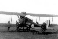
One of the work-horses of the artillery observation flights, the L.V.G. C V, with an interesting insignia displayed on the fuselage.
-
J.Herris - LVG Aircraft of WWI. Volume 2: Types C.II-C.V /Centennial Perspective/ (35)
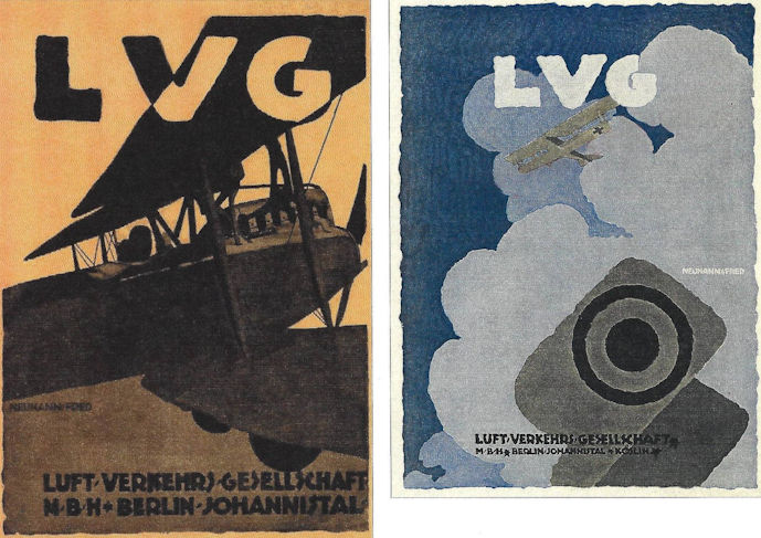
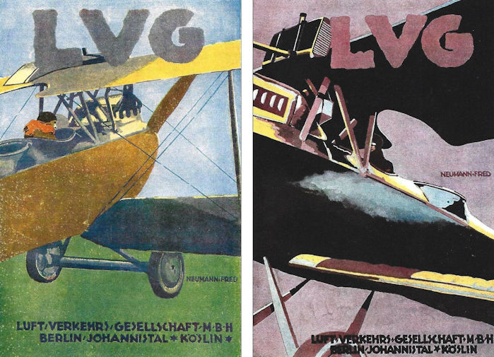
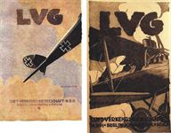
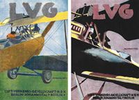
Fred Neumann was the artist for the LVG posters reproduced throughout these volumes.
-
J.Herris - LVG Aircraft of WWI. Volume 2: Types C.II-C.V /Centennial Perspective/ (35)
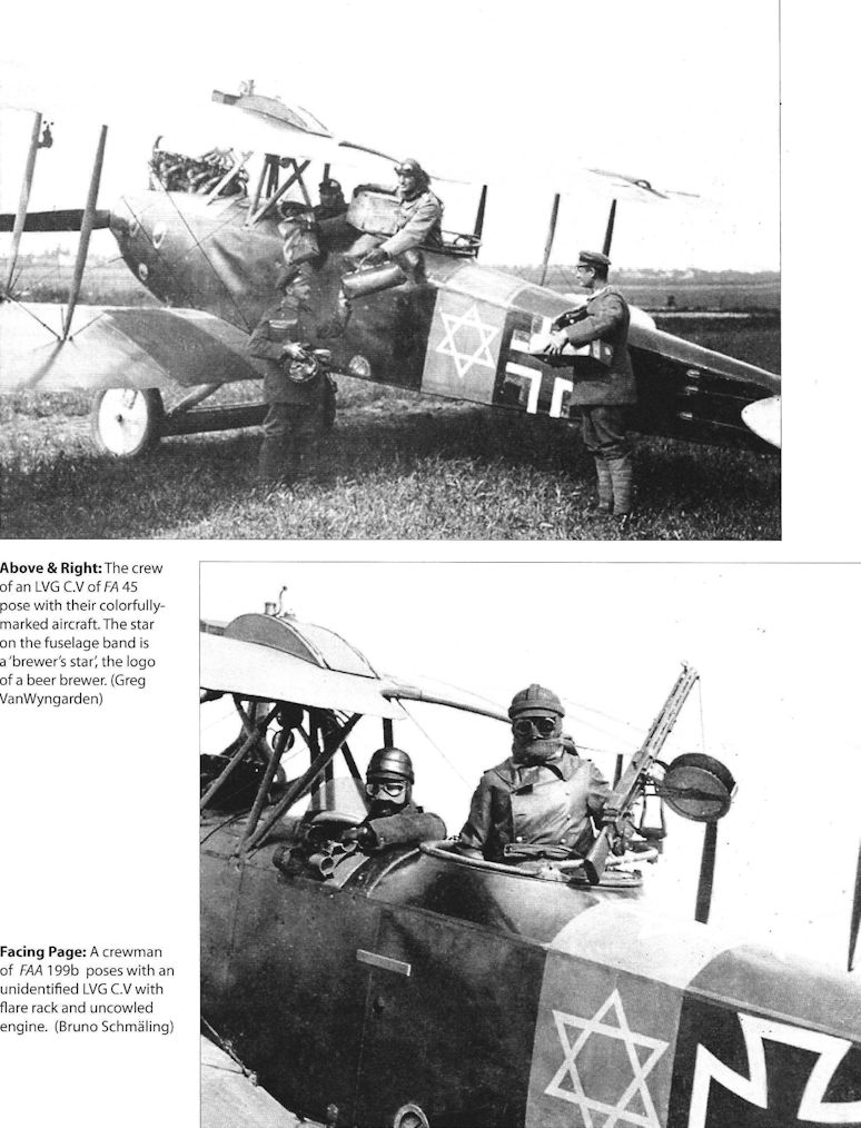
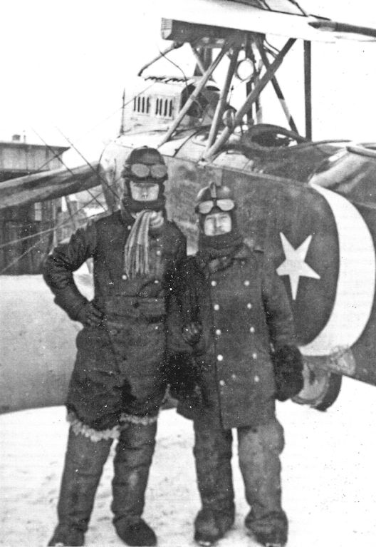
The crew of an LVG C.V of FA 45 pose with their colorfully-marked aircraft. The star on the fuselage band is a 'brewer's star', the logo of a beer brewer. (Greg VanWyngarden)
-
J.Herris - LVG Aircraft of WWI. Volume 2: Types C.II-C.V /Centennial Perspective/ (35)
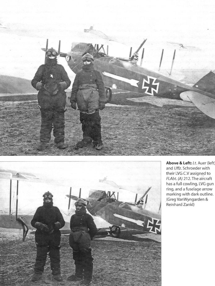
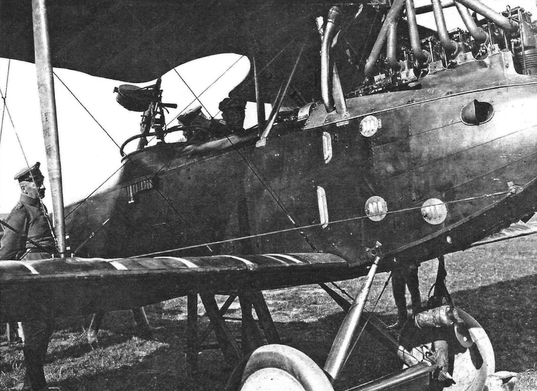
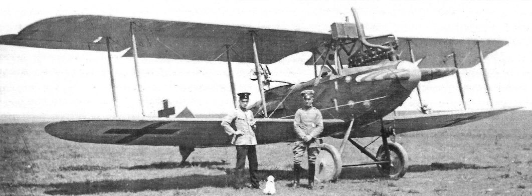
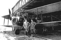
Lt. Auer (left) and Uffz. Schroeder with their LVG C.V assigned to Fl.Abt. (A) 212. The aircraft has a full cowling, LVG gun ring, and a fuselage arrow marking with dark outline. (Greg VanWyngarden & Reinhard Zankl)
-
J.Herris - LVG Aircraft of WWI. Volume 2: Types C.II-C.V /Centennial Perspective/ (35)
An LVG C.V from and unidentified unit is surrounded with personnel getting it ready for flight. The C.V has 1917 insignia and a white fuselage band with tactical number 5 in it. The aircraft has a fully-cowled engine and LVG gun ring. (Reinhard Zankl)
-
J.Herris - LVG Aircraft of WWI. Volume 2: Types C.II-C.V /Centennial Perspective/ (35)
LVG C.V with three-pointed star insignia and observer named Zimmerman; there is no other data available. (Greg VanWyngarden)
-

J.Herris - LVG Aircraft of WWI. Volume 2: Types C.II-C.V /Centennial Perspective/ (35)
LVG C.V of FA(A) 212; the star and crescent is a personal marking. (Greg VanWyngarden)
-

J.Herris - LVG Aircraft of WWI. Volume 2: Types C.II-C.V /Centennial Perspective/ (35)
Crew in their LVG C.V of Flieger-Abteilung (A) 199b. (Greg VanWyngarden)
-
J.Herris - LVG Aircraft of WWI. Volume 2: Types C.II-C.V /Centennial Perspective/ (35)
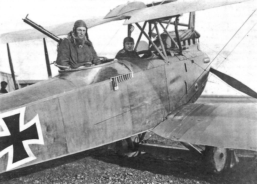
A crewman of FAA 199b poses with an unidentified LVG C.V with flare rack and uncowled engine. (Bruno Schmaling)
-
J.Herris - LVG Aircraft of WWI. Volume 2: Types C.II-C.V /Centennial Perspective/ (35)
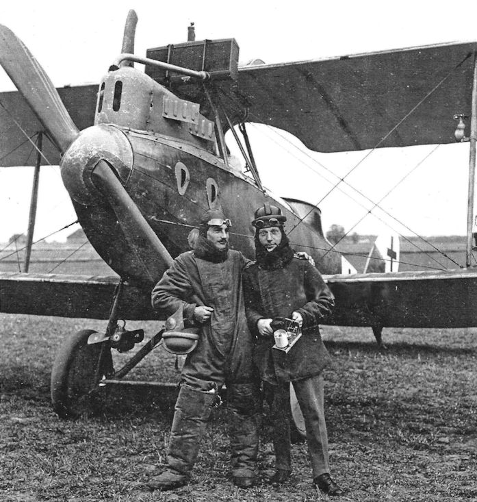
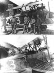
Two views of a crew from Flieger Abteilung (A) 233 with their LVG C.V. The pilot is Uffz. Richard Scholl and observer is Lt.d.R. Eugen Anderer. They were both KIA together in a flight on 26 Sept. 1918. The aircraft has a fully stocked flare rack for the observer, LVG gun mount with machine gun with telescopic sight, uncowled engine, and the unit markings on the nose. These may have been different colors for each crew. (Bruno Schmaling)
-
J.Herris - LVG Aircraft of WWI. Volume 2: Types C.II-C.V /Centennial Perspective/ (35)
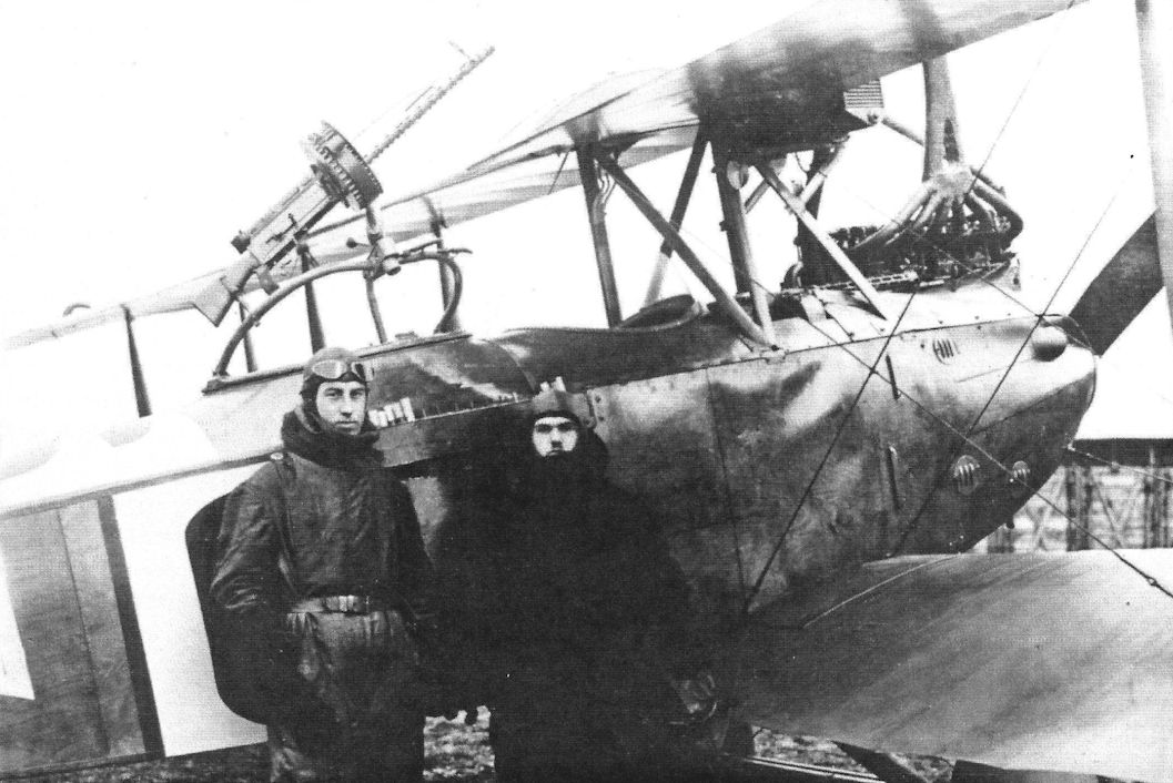
Lt. Forster and Lt. Hitschler and their LVG C.V ready for their next mission of FliegerAbteilung (A) 298b, at Les Baraques airfield in the spring of 1918. Their ground crew is in the bottom photo.
-
J.Herris - LVG Aircraft of WWI. Volume 2: Types C.II-C.V /Centennial Perspective/ (35)
The crew of a Marine Flieger Abteilung with their LVG C.V. The aircraft has an unusual out-board wireless dynamo with its antenna weight hanging below the fuselage. The observer has a full cartridge rack and a Parabellum LMG 14 machine gun with telescopic sight. The aircraft carries mid-1918 insignia.
-
J.Herris - LVG Aircraft of WWI. Volume 2: Types C.II-C.V /Centennial Perspective/ (35)
The crew of an apparently new LVG C.V of FA(A) 238 are photographed in it. The aircraft is too new to have its tactical number painted on it yet. (Greg VanWyngarden)
-
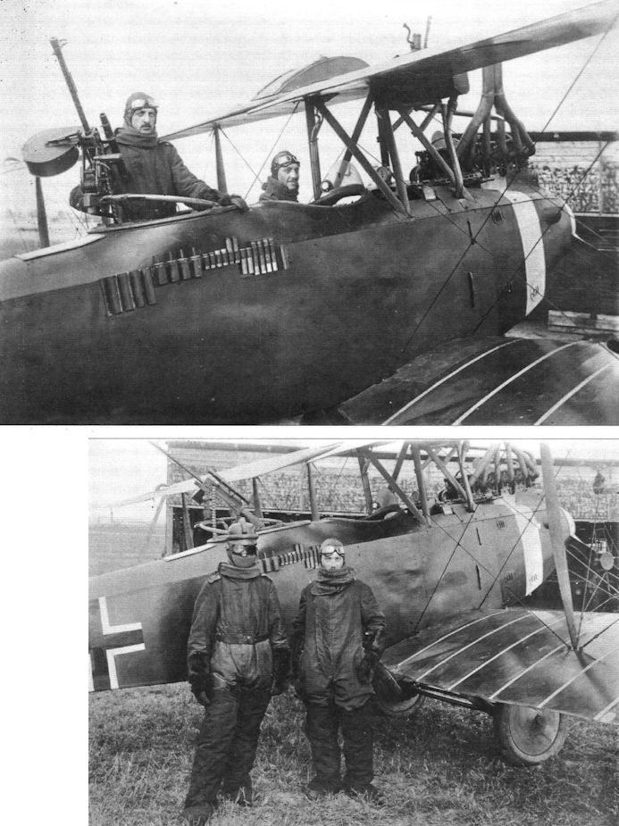
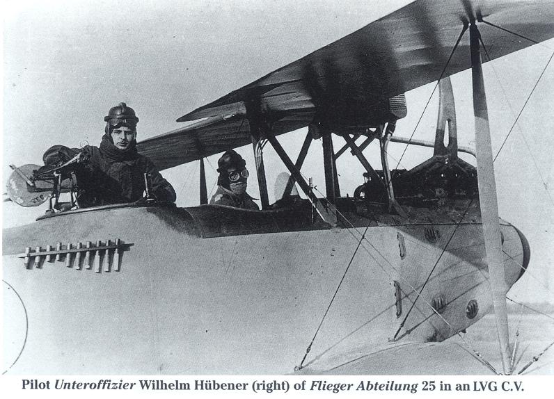
Сайт - Pilots-and-planes /WWW/
LVG C.V of Flieger Abteilung 25 with painted fuselage. Uffz. Wilhelm Hubner was the pilot. (Greg VanWyngarden)
Pilot Unteroffizier Wilhelm Hubener (right) of FLieger Abteilung 25 in an LVG C.V. -

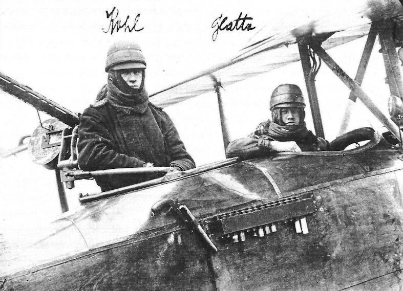
J.Herris - LVG Aircraft of WWI. Volume 2: Types C.II-C.V /Centennial Perspective/ (35)
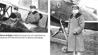
Ltn.d.R. Josef Kohl and pilot Glatta in an LVG C.V of FA 48. The pilot's name "Glatta" seems to be a nickname or mistaken rendering of Oblt.d.R. Friedrich Klatte. The observer is well supplied with flares and flare gun and the crew are fully clothed for flight. (Bruno Schmaling)
-

J.Herris - LVG Aircraft of WWI. Volume 2: Types C.II-C.V /Centennial Perspective/ (35)
The crew photographed by LVG C.V tactical '6' of FA(A) 238 before wrecking it. (Greg VanWyngarden)
-

J.Herris - LVG Aircraft of WWI. Volume 2: Types C.II-C.V /Centennial Perspective/ (35)
LVG C.V observer demonstrates his gun. The aerial weight is visible below the fuselage. (Greg VanWyngarden)
-
J.Herris - LVG Aircraft of WWI. Volume 2: Types C.II-C.V /Centennial Perspective/ (35)
An LVG C.V being run up by a mechanic. The engine is fully cowled and a small flare rack is fitted along with the usual LVG gun ring. A 1917 insignia is barely visible.
-

J.Herris - LVG Aircraft of WWI. Volume 2: Types C.II-C.V /Centennial Perspective/ (35)
Unidentified crew of an LVG C.V of FA 48. The observer is well supplied with flares and flare gun. (Bruno Schmaling)
-
J.Herris - LVG Aircraft of WWI. Volume 2: Types C.II-C.V /Centennial Perspective/ (35)
LVG C.V tactical number 1 of an unknown unit. (Greg VanWyngarden)
-
J.Herris - LVG Aircraft of WWI. Volume 2: Types C.II-C.V /Centennial Perspective/ (35)
LVG C.V of Fl. Abt. 265 Minna. (Greg VanWyngarden)
-

J.Herris - LVG Aircraft of WWI. Volume 2: Types C.II-C.V /Centennial Perspective/ (35)
Unidentified LVG C.V in early 1918 insignia runs up its engine.
-

J.Herris - LVG Aircraft of WWI. Volume 2: Types C.II-C.V /Centennial Perspective/ (35)
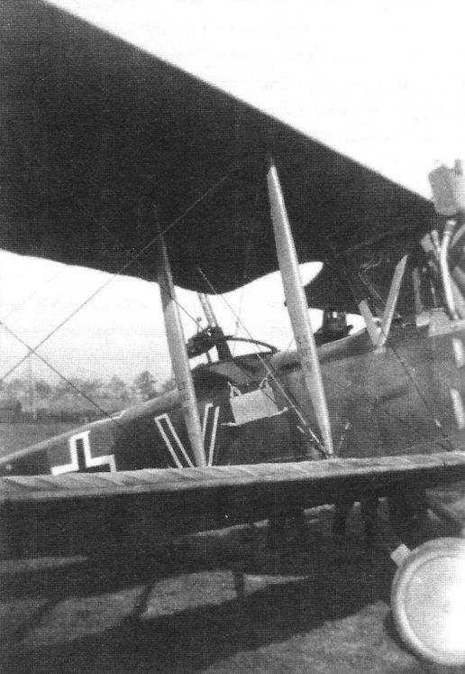
An LVG C.V with black and white 'V' marking.
-

J.Herris - LVG Aircraft of WWI. Volume 2: Types C.II-C.V /Centennial Perspective/ (35)
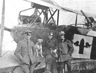
LVG C.V of Flieger-Abteilung (A) 199b with crewman, dog mascot, and good luck charm. (Greg VanWyngarden)
-
J.Herris - LVG Aircraft of WWI. Volume 2: Types C.II-C.V /Centennial Perspective/ (35)
Unknown aviator of Flieger-Abteilung (A) 199b with his LVG C.V. (Greg VanWyngarden)
-
J.Herris - LVG Aircraft of WWI. Volume 2: Types C.II-C.V /Centennial Perspective/ (35)
Official closeup photo of an LVG C.V and its pilot. (Greg VanWyngarden)
-

J.Herris - LVG Aircraft of WWI. Volume 2: Types C.II-C.V /Centennial Perspective/ (35)
LVG C.V of Flieger-Abteilung (A) 199b with crewman. (Greg VanWyngarden)
-

J.Herris - LVG Aircraft of WWI. Volume 2: Types C.II-C.V /Centennial Perspective/ (35)
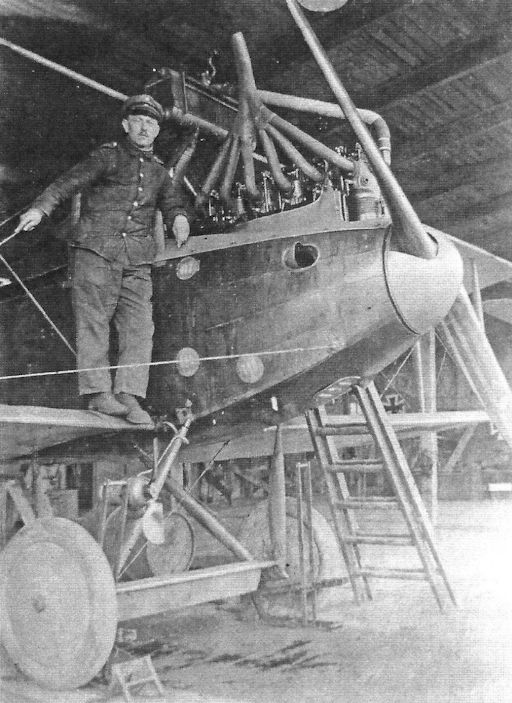
LVG C.V with exposed engine in a hangar. (Greg VanWyngarden)
-
J.Herris - LVG Aircraft of WWI. Volume 2: Types C.II-C.V /Centennial Perspective/ (35)
Lt.d.R. Paul Forster and Lt.d.R. Hitschler of FliegerAbteilung (A) 298b, at Les Baraques airfield in the spring of 1918 with their LVG C.V ready for another mission. The upper cowling has been removed for operation in warm weather. A dynamo is fitted to the undercarriage.
-
J.Herris - LVG Aircraft of WWI. Volume 2: Types C.II-C.V /Centennial Perspective/ (35)
Perhaps a family visit to a unit while training in Germany with an LVG C.V in the background. (Bruno Schmaling)
-
J.Herris - LVG Aircraft of WWI. Volume 2: Types C.II-C.V /Centennial Perspective/ (35)
The LVG C.V of Arthur Laumann, on the left, when he was a pilot in FAA 265. Later he transferred to fighters, and as a member of Jasta 66 and later commander of Jasta 10, he scored 28 victories and won the Pour le Merite. (Greg VanWyngarden)
-
J.Herris - LVG Aircraft of WWI. Volume 2: Types C.II-C.V /Centennial Perspective/ (35)
Lt.d.R. Anderer (observer) and pilot Uffz. Richard Scholl with ground personnel from FliegerAbteilung(A) 233 with an unidentified and well-maintained LVG C.V. The aircraft has a fully stocked flare rack for the observer, LVG gun mount with machine gun with telescopic sight, uncowled engine, and unit markings on the nose. The wings are covered in camouflage fabric with light rib tapes and it has 1918 insignia. (Bruno Schmaling)
-

J.Herris - LVG Aircraft of WWI. Volume 2: Types C.II-C.V /Centennial Perspective/ (35)
LVG C.V aircraft; that above is fitted with mudguards that are certainly useful. (Greg VanWyngarden)
-
J.Herris - LVG Aircraft of WWI. Volume 2: Types C.II-C.V /Centennial Perspective/ (35)
LVG C.V of FA(A) 256 and its crew of Oblt. Otto Fischer and Gefreiter Schmalt, May 1918. (Greg VanWyngarden)
-

J.Herris - LVG Aircraft of WWI. Volume 2: Types C.II-C.V /Centennial Perspective/ (35)
LVG C.V of an unidentified unit with German battle ensign between the national insignia and the tactical number 4. (Greg VanWyngarden)
-
J.Herris - LVG Aircraft of WWI. Volume 2: Types C.II-C.V /Centennial Perspective/ (35)
This is the crew of Lt.d.R. Paul Forster and Lt.d.R. Hitschler of FliegerAbteilung (A) 298b, at Les Baraques airfield in the spring of 1918.
-

J.Herris - LVG Aircraft of WWI. Volume 2: Types C.II-C.V /Centennial Perspective/ (35)
Sgt. Friedrich Heinlein of Flieger-Abteilung (A) 199b with an LVG C.V. (Greg VanWyngarden)
-

J.Herris - LVG Aircraft of WWI. Volume 2: Types C.II-C.V /Centennial Perspective/ (35)
Smiling pilot from FliegerAbteilung (A) 199b in an unidentified LVG C.V with 1917 insignia. The aircraft has a sizeable flare rack for the observer. (Bruno Schmaling)
-
J.Herris - LVG Aircraft of WWI. Volume 2: Types C.II-C.V /Centennial Perspective/ (35)
Lt. Stein and his LVG C.V in late 1917.
-

J.Herris - LVG Aircraft of WWI. Volume 2: Types C.II-C.V /Centennial Perspective/ (35)
The crew of an LVG C.V with Barograph box. (Greg VanWyngarden)
-

J.Herris - LVG Aircraft of WWI. Volume 2: Types C.II-C.V /Centennial Perspective/ (35)
Unknown crewmen photographed with an LVG C.V of unknown units. The aircraft at right has no spinner.
-

J.Herris - LVG Aircraft of WWI. Volume 2: Types C.II-C.V /Centennial Perspective/ (35)
Unidentified aircrew and LVG C.V aircraft of FA(A) 233. Pilot Uffz. Richard Scholl at right stands by a mascot/good luck charm. (Bruno Schmaling)
-
J.Herris - LVG Aircraft of WWI. Volume 2: Types C.II-C.V /Centennial Perspective/ (35)
LVG C.V of FA(A) 233 with "Feldgrau" doll/mascot and barograph. (Bruno Schmaling)
-
J.Herris - LVG Aircraft of WWI. Volume 2: Types C.II-C.V /Centennial Perspective/ (35)
Unidentified LVG C.V undergoing maintenance in the snow. (Greg VanWyngarden)
-
J.Herris - LVG Aircraft of WWI. Volume 2: Types C.II-C.V /Centennial Perspective/ (35)
Unidentified LVG C.V. (Reinhard Zankl)
-
J.Herris - LVG Aircraft of WWI. Volume 2: Types C.II-C.V /Centennial Perspective/ (35)
LVG C.V with striped nose and no cowling with crew in a hangar; the ground crew is behind. (Greg VanWyngarden)
-

J.Herris - LVG Aircraft of WWI. Volume 2: Types C.II-C.V /Centennial Perspective/ (35)
LVG C.V with no spinner and exposed engine with a pilot of a postwar Freikorps unit. The weights table was painted on the fuselage in white. (Greg VanWyngarden)
-
J.Herris - LVG Aircraft of WWI. Volume 2: Types C.II-C.V /Centennial Perspective/ (35)
LVG C.V with no spinner and exposed engine and crew with pets. (Greg VanWyngarden)
-
J.Herris - LVG Aircraft of WWI. Volume 3: Types C.VI-C.XI & Fighters /Centennial Perspective/ (36)
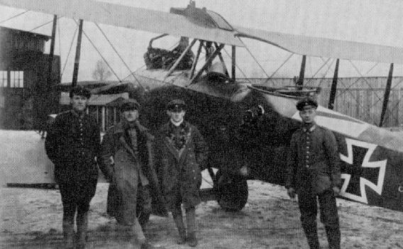
The crew of Vzfw. Georg Gund (left) and observer Lt.d.R. Karl Eisenmenger of Fl. Abt. (A) 263 were on an artillery spotting flight in this LVG on 23 May 1918 when they were attacked by six British fighters. They fought their way back, claimed five of the fighters shot down, and were actually credited with four (in one fight). That is why they were memorialized in Sanke Card #636. Gund was killed in a crash on 9 June 1918 and Eisenmenger was badly wounded on 17 June 1918. Here Eisenmenger has a full rack of flares. (Peter M. Grosz Collection/SDTB)
-

J.Herris - LVG Aircraft of WWI. Volume 2: Types C.II-C.V /Centennial Perspective/ (35)
LVG C.V tactical number 6 of an unknown unit; the crew is getting ready to fly. (Greg VanWyngarden)
-

J.Herris - LVG Aircraft of WWI. Volume 2: Types C.II-C.V /Centennial Perspective/ (35)
LVG C.V aircraft of Marine Schusta 1 or II with an 'X' marking. (Greg VanWyngarden)
-
J.Herris - LVG Aircraft of WWI. Volume 2: Types C.II-C.V /Centennial Perspective/ (35)
Franz und Emil with their LVG C.V; the aircraft has a full cowling, LVG gun ring, and full flare rack. (Bruno Schmaling)
-
J.Herris - LVG Aircraft of WWI. Volume 2: Types C.II-C.V /Centennial Perspective/ (35)
Two views of an LVG C.V of FliegerAbteilung 7 and its crew.
-
J.Herris - LVG Aircraft of WWI. Volume 2: Types C.II-C.V /Centennial Perspective/ (35)
LVG C.V and crew. The weight table is clearly stenciled in dark letters. (Greg VanWyngarden)
-
J.Herris - LVG Aircraft of WWI. Volume 2: Types C.II-C.V /Centennial Perspective/ (35)
LVG C.V and crew. A barograph box is attached to the inner struts. (Greg VanWyngarden)
-
J.Herris - LVG Aircraft of WWI. Volume 2: Types C.II-C.V /Centennial Perspective/ (35)
Additional views of Lt.d.R. Josef Kohl, an observer of FA 48 with his LVG C.V. (Bruno Schmaling)
-

J.Herris - LVG Aircraft of WWI. Volume 2: Types C.II-C.V /Centennial Perspective/ (35)
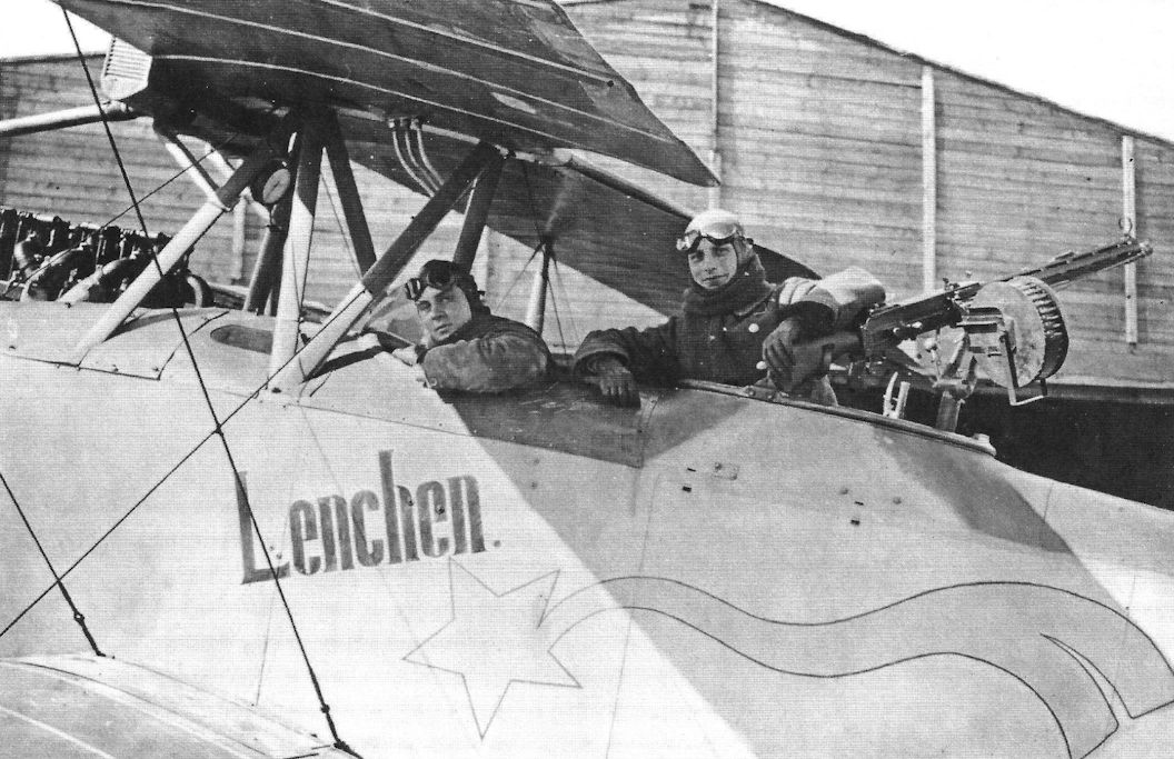
The crew of LVG C.V Lenchen display the colorful marking on their aircraft. (Peter M. Grosz Collection/SDTB)
-

J.Herris - LVG Aircraft of WWI. Volume 2: Types C.II-C.V /Centennial Perspective/ (35)
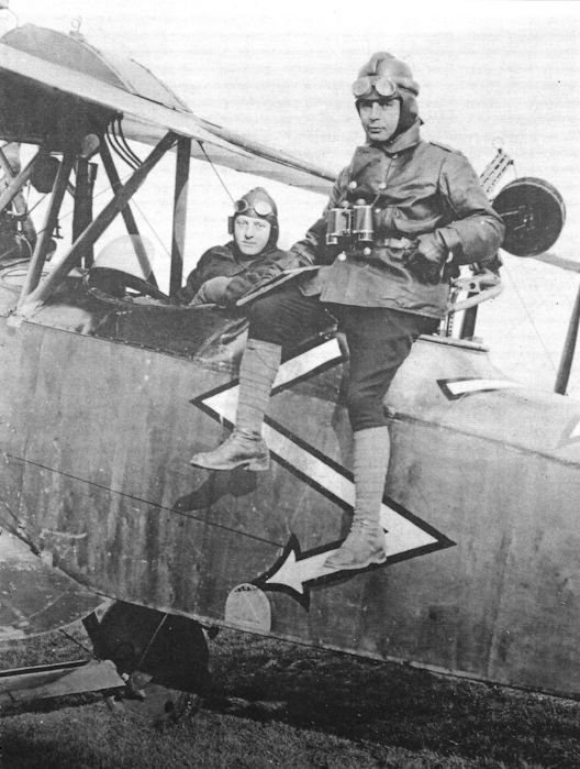
Franz und Emil with their LVG C.V display the striking zig-zag marking on their aircraft. (Peter M. Grosz Collection/SDTB)
-
J.Herris - LVG Aircraft of WWI. Volume 2: Types C.II-C.V /Centennial Perspective/ (35)
Crew of LVG C.V of FAA 257; the aircraft has a full cowling, LVG gun ring, and full flare rack. (Bruno Schmaling)
-
J.Herris - LVG Aircraft of WWI. Volume 2: Types C.II-C.V /Centennial Perspective/ (35)
LVG C.V with the crew getting ready to fly. (Greg VanWyngarden)
-
J.Herris - LVG Aircraft of WWI. Volume 2: Types C.II-C.V /Centennial Perspective/ (35)
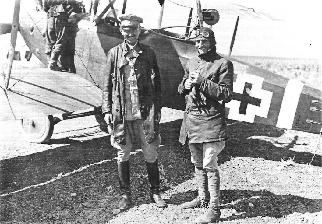
Lt. Weyer, Kofi of Heeresgruppe F in Palestine on the left. On the right is Hauptmann Franz Walz, commander of Fl. Abt. 304b in Palestine. Walz had previously been CO of Jasta Boelcke, then Jasta 34b on the Western Front and would win the Pour le Merite for his stellar service in Palestine. The LVG C.V has been patched. (Bruno Schmaling)
-

-
J.Herris - LVG Aircraft of WWI. Volume 2: Types C.II-C.V /Centennial Perspective/ (35)
LVG C.V of an unidentified unit with a winged artillery shell as a marking. (Greg VanWyngarden)
-
J.Herris - LVG Aircraft of WWI. Volume 2: Types C.II-C.V /Centennial Perspective/ (35)
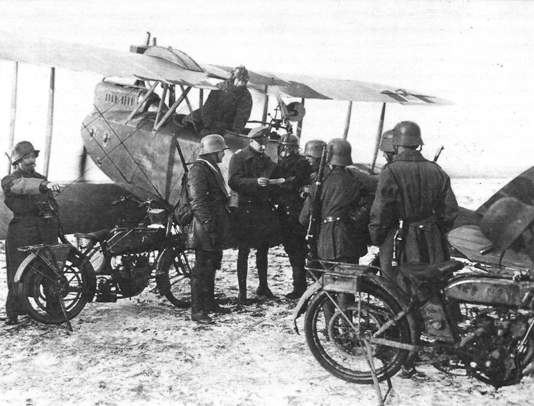
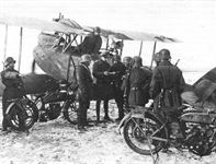
Crew of an LVG C.V meets with some motorcycle dispatch riders. (Greg VanWyngarden)
-

J.Herris - LVG Aircraft of WWI. Volume 2: Types C.II-C.V /Centennial Perspective/ (35)
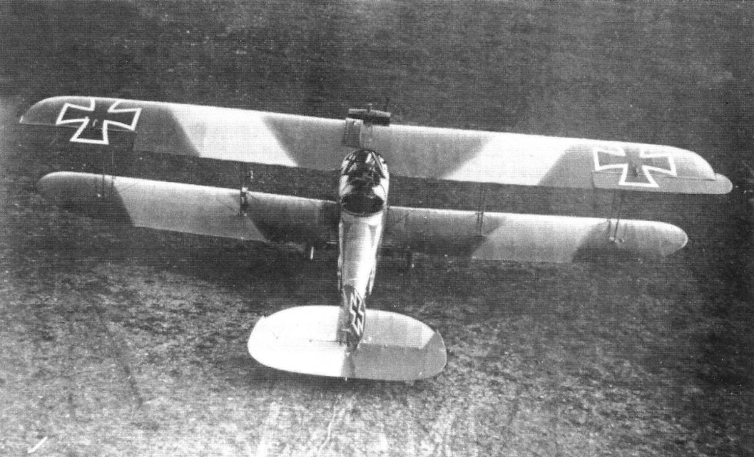
Rearview of the LVG C.V camouflage pattern for the initial production aircraft.
-

J.Herris - LVG Aircraft of WWI. Volume 2: Types C.II-C.V /Centennial Perspective/ (35)
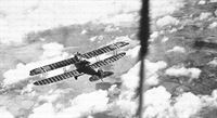
LVG C.V of Flieger-Abteilung (A) 199b in flight without spinner. (Greg VanWyngarden)
-
J.Herris - LVG Aircraft of WWI. Volume 2: Types C.II-C.V /Centennial Perspective/ (35)
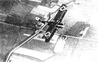
An unidentified LVG C.V in flight wears 1918 insignia and camouflage wing fabric with dark rib tapes.
-

J.Herris - LVG Aircraft of WWI. Volume 2: Types C.II-C.V /Centennial Perspective/ (35)
Two different LVG C.V aircraft of FAA 199b in flight. The upper is in mid-1918 camouflage and markings, and the lower is in 1917 camouflage and markings. (Bruno Schmaling)
-
J.Herris - LVG Aircraft of WWI. Volume 2: Types C.II-C.V /Centennial Perspective/ (35)
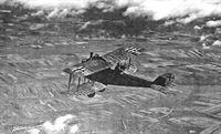
LVG C.V of Flieger-Abteilung (A) 199b in flight with the observer using a camera. (Greg VanWyngarden)
-
J.Herris - LVG Aircraft of WWI. Volume 2: Types C.II-C.V /Centennial Perspective/ (35)
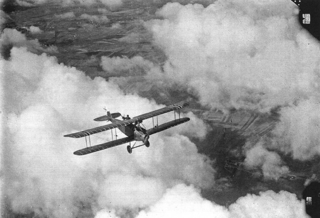
LVG C.V of Flieger-Abteilung (A) 199b in flight over the clouds. (Greg VanWyngarden)
-
J.Herris - LVG Aircraft of WWI. Volume 2: Types C.II-C.V /Centennial Perspective/ (35)
LVG C.V tactical no. 1 Saxon FA(A) 208; the swastika is the unit marking. (Greg VanWyngarden)
-

J.Herris - LVG Aircraft of WWI. Volume 2: Types C.II-C.V /Centennial Perspective/ (35)
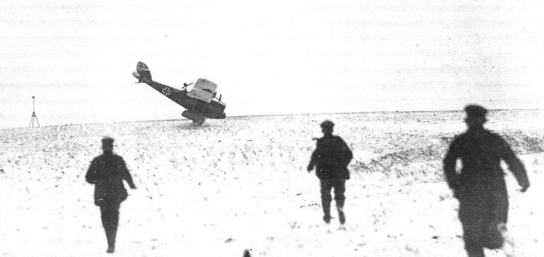
LVG C.V approaching for a one-wheel landing. (Greg VanWyngarden)
-
J.Herris - LVG Aircraft of WWI. Volume 2: Types C.II-C.V /Centennial Perspective/ (35)
LVG C.V after a one-wheel landing; the ground crew are rushing to help. (Greg VanWyngarden)
-
J.Herris - LVG Aircraft of WWI. Volume 2: Types C.II-C.V /Centennial Perspective/ (35)
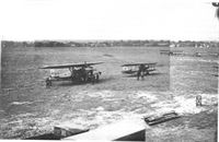
LVG C.V aircraft of Marine Schusta 1 or II testing engines before take-off. The center aircraft has a Rat emblem.
-
J.Herris - LVG Aircraft of WWI. Volume 3: Types C.VI-C.XI & Fighters /Centennial Perspective/ (36)
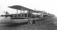
LVG C.VI 120X4/18 (work number 5105) heads a lineup of LVG C.V and C.VI aircraft thought to be the final wartime production batch from LVG in October 1918. Behind it is a C.V, offering an opportunity to compare nose contours.
Другие самолёты на фотографии: LVG C.VI - Германия - 1918
-
J.Herris - LVG Aircraft of WWI. Volume 2: Types C.II-C.V /Centennial Perspective/ (35)
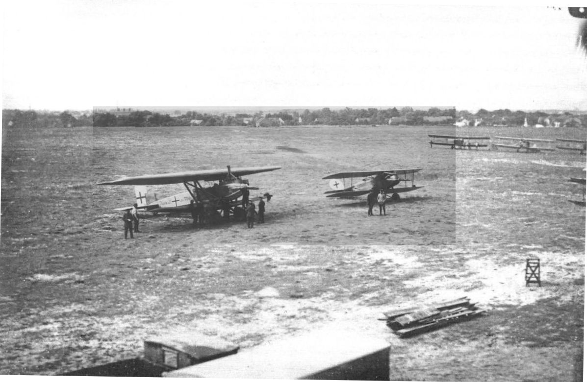
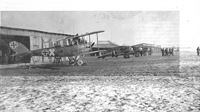
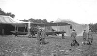
A unit equipped with the LVG C.V in the field; note the tent hangars. (Rob Bell)
-
C.Owers, J.Herris - Hannover Aircraft of WWI /Centennial Perspective/ (46)
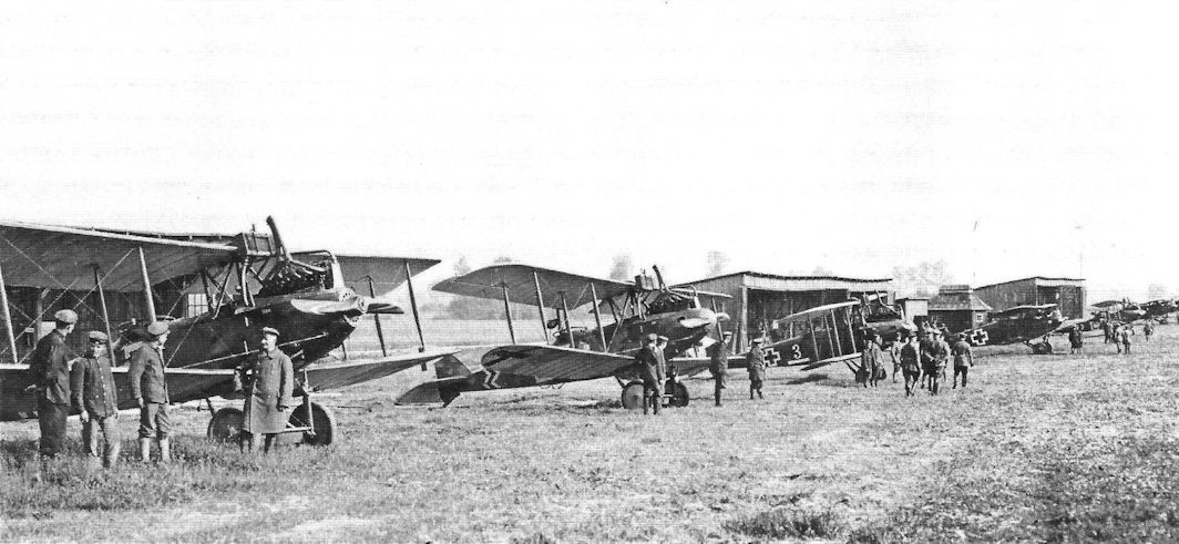
Flieger-Abteilung lineup with several Hannover CL.II, a DFW C.V, and two LVG C.Vs.
Другие самолёты на фотографии: DFW C.V - Германия - 1916Hannover (Hawa) CL.II/CL.III/CL.IIIa - Германия - 1917
-
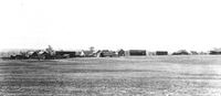
J.Herris - LVG Aircraft of WWI. Volume 2: Types C.II-C.V /Centennial Perspective/ (35)
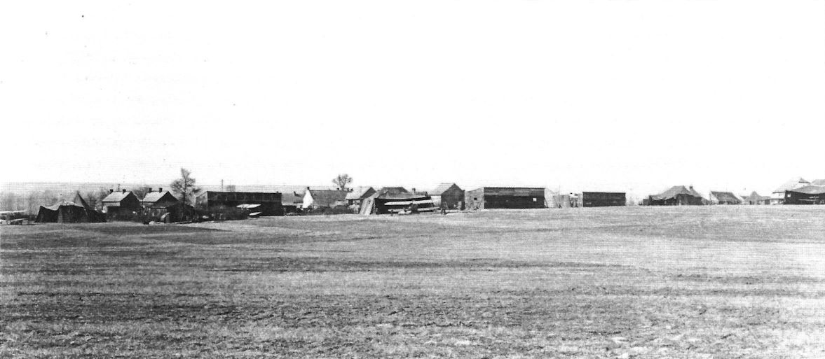
The airfield of an Abteilung equipped with LVG C.V aircraft.
-
J.Herris - Halberstadt Aircraft of WWI. Volume 2: CL.IV-CLS.I & Fighters /Centennial Perspective/ (45)
Not the best of photos, but it shows some of the diversity of FA 431's aircraft - from left to right, Junkers J.I 750/17, Halb. CL.IV and two LVGs, a C.VI and a C.V. (August Qoos album via Greg VanWyngarden)
Другие самолёты на фотографии: Halberstadt CL.IV - Германия - 1918Junkers J.I / J 4 - Германия - 1917LVG C.VI - Германия - 1918
-
J.Herris - LVG Aircraft of WWI. Volume 2: Types C.II-C.V /Centennial Perspective/ (35)
LVG C.V aircraft and a DFW C.V in the right background with bold markings that may be from Schusta 29b. (Greg VanWyngarden)
Другие самолёты на фотографии: DFW C.V - Германия - 1916
-
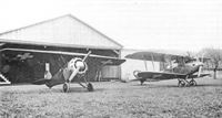
J.Herris - Pfalz Aircraft of WWI /Centennial Perspective/ (5)
A Pfalz D.IIIa at Jastaschule with an LVG C.V.
Другие самолёты на фотографии: Pfalz D.III/D.IIIa - Германия - 1917
-
J.Herris - AEG Aircraft of WWI /Centennial Perspective/ (16)
AEG G.IV G.1131/16 from the second G.IV production batch is being evaluated with other captured German aircraft, including an LVG C.V and Albatros D.Va, at the French aviation test center at Villacoublay.
Другие самолёты на фотографии: AEG G.IV - Германия - 1916Albatros D.V/D.Va - Германия - 1917
-
J.Herris - Rumpler Aircraft of WWI /Centennial Perspective/ (11)
Rumpler C.IV 8424/16 Dalila of the first production batch undergoes maintenance.This early production C.IV is the subject of Steve Anderson's cover painting. LVG C.V aircraft are on both sides of Dalila.
Другие самолёты на фотографии: Rumpler C.IV - Германия - 1916
-

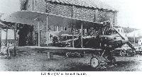
M.Dusing - German Aviation Industry in WWI. Volume 1 /Centennial Perspective/ (84)
"C hangar" of the LVG in Johannisthal.
-
J.Herris - LVG Aircraft of WWI. Volume 2: Types C.II-C.V /Centennial Perspective/ (35)
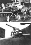
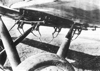
LVG C.V bomb racks. Although designed for reconnaissance, the C.V could carry a 50 kg. (110 pound) bomb load composed of four 12.5 kg PuW bombs on the racks shown here.
-

J.Herris - LVG Aircraft of WWI. Volume 2: Types C.II-C.V /Centennial Perspective/ (35)
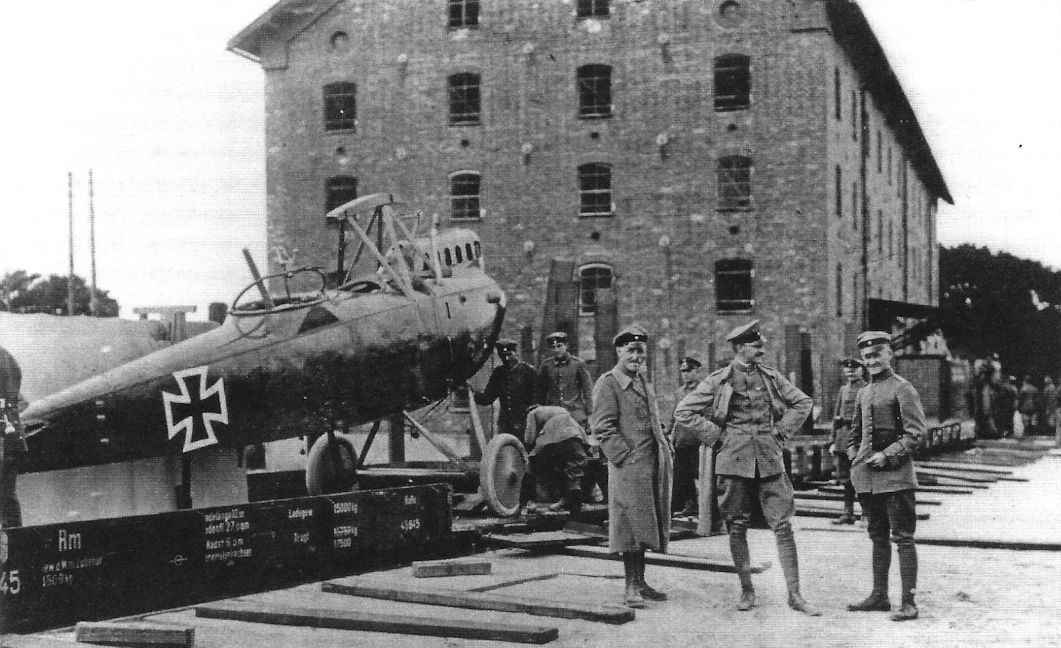
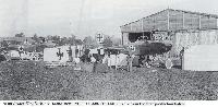
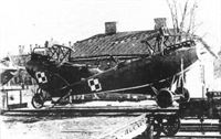
An LVG C.V loaded on a train arrives at FEA Schleissheim.
-

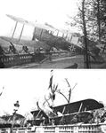
R.Bennett - Last Gathering of Eagles 1918-1920 /Aeronaut/
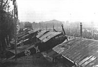
The Inter-Allied Baltic Commission intercepted a shipment of German aircraft on its arrival in East Prussia and returned it to Lithuania. This train carried LVG C.VI 12017/18 (ex-FA 433), Halb. C.V (Av) 6859/18, Alb. D.III (OAW) D.5160/17, LVG C.V 9652/17, one DFW C.V, and three Alb. J.IIs. (Moshe Bukhman)
Другие самолёты на фотографии: Albatros D.III - Германия - 1916Albatros J.II - Германия - 1918DFW C.V - Германия - 1916Halberstadt C.V/C.IX - Германия - 1918LVG C.VI - Германия - 1918
-
J.Herris - LVG Aircraft of WWI. Volume 2: Types C.II-C.V /Centennial Perspective/ (35)
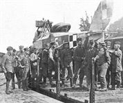
An Abteilung equipped with LVG C.V aircraft is packed for transportation to the front.
-
J.Herris - LVG Aircraft of WWI. Volume 2: Types C.II-C.V /Centennial Perspective/ (35)
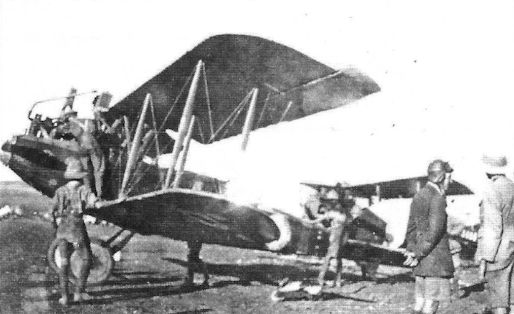
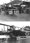
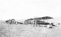
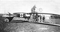
The photo shows an LVG C.V surrounded by British aircraft in the Middle East.
-

J.Herris - LVG Aircraft of WWI. Volume 2: Types C.II-C.V /Centennial Perspective/ (35)
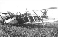
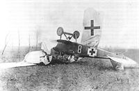
LVG C.V after capture in the Middle East.
-
J.Herris - LVG Aircraft of WWI. Volume 2: Types C.II-C.V /Centennial Perspective/ (35)
Captured LVG C.V with a BK marking is shown here at Villacoublay. (Greg VanWyngarden)
-
J.Herris - LVG Aircraft of WWI. Volume 2: Types C.II-C.V /Centennial Perspective/ (35)
LVG C.V with BK marking on display in Paris on 20 October 1918. (Greg VanWyngarden)
-
J.Herris - LVG Aircraft of WWI. Volume 2: Types C.II-C.V /Centennial Perspective/ (35)
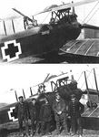
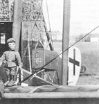
LVG C.V after capture by the British, who have applied British markings. Removal of the wings makes the various details more visible, including the fixed pilot's machine gun. The spinner has been removed.
-
J.Herris - LVG Aircraft of WWI. Volume 2: Types C.II-C.V /Centennial Perspective/ (35)
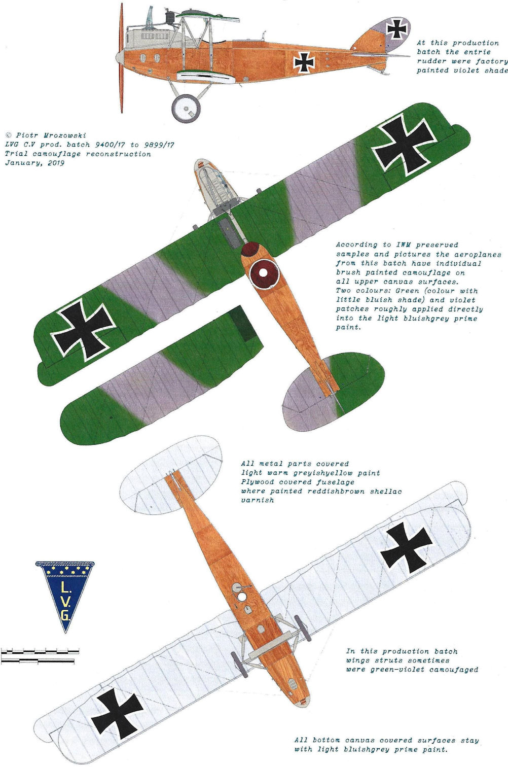
LVG C.V captured by the British and given the captured aircraft designation G-3-5 (G/3rd Brigade/5) and British markings. It was C.V 9746/17, captured on 29 April 1918 with Benz Bz.IV 32578. It had Spandau 9093 and Parabellum 4092. Pieces of its fabric still exist in the IWM. The rudder was "mauve with a black cross"and the fuselage was varnished yellow. The mainplanes and tailplane undersides were (slightly greenish) Sky Blue (Methuen 25A3 pale green) on light grey fabric. Mainplane upper surfaces were camouflaged in Mauve (Methuen 14E3 greyish magenta) and green (Methuen 26D/E3 Dull green) on grey fabric.
-

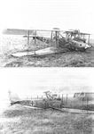
Журнал - Flight за 1918 г.
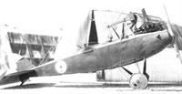
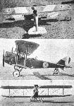
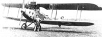
A recent type of German L.V.G. biplane of the C.V class.
-
Журнал - Flight за 1918 г.
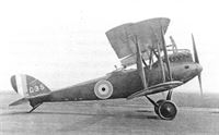
Side view of the L.V.G. C. V. biplane.
-
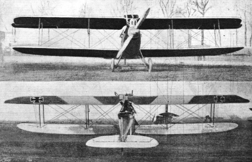
Журнал - Flight за 1918 г.
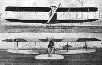
Front and rear views of the L.V.G. C. V. biplane.
-
Журнал - Flight за 1918 г.
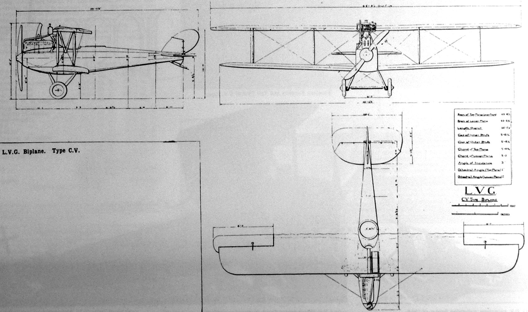
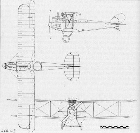
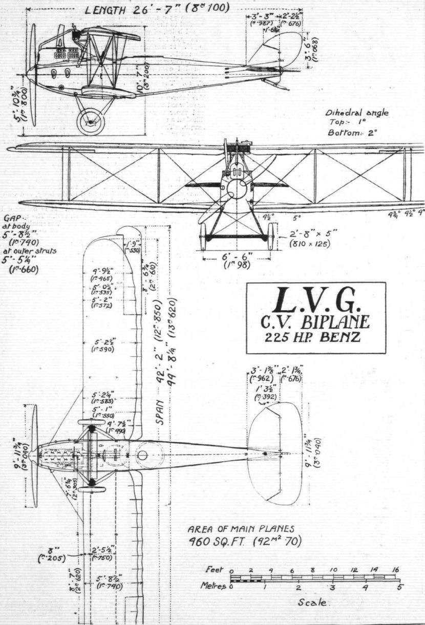
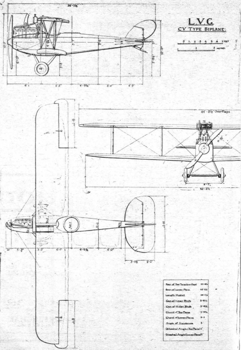
Three views of the Type C. V. L.V.G. Biplane.
-
J.Herris - LVG Aircraft of WWI. Volume 2: Types C.II-C.V /Centennial Perspective/ (35)
LVG C.V 9812/17 (Wk Number 2813), which landed at Catigny on 16 February 1918 and was captured. It was assigned British "captured German aircraft" number G.135. It had 200 hp Benz Bz.IV #32668, and Garuda propeller 14881 of walnut and mahogany. Spandau Gun 3715 and Parabellum 3350. The fuselage components were dated 6 December 1917 and wings were dated 29 November 1917. The varnished plywood fuselage and fin were described as "yellow" and the wings were camouflaged green and mauve on top and light blue underneath. The photo above is C.V 9812/17 repainted in British markings.
-
-

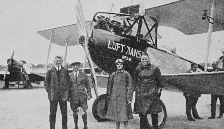
J.Stroud - European Transport Aircraft since 1910 /Putnam/
Deutsche Lufthansa’s L.V.G. Ch 2 D-1179 Bisam (Musk) appears to have been a modified L.V.G. C V.
-
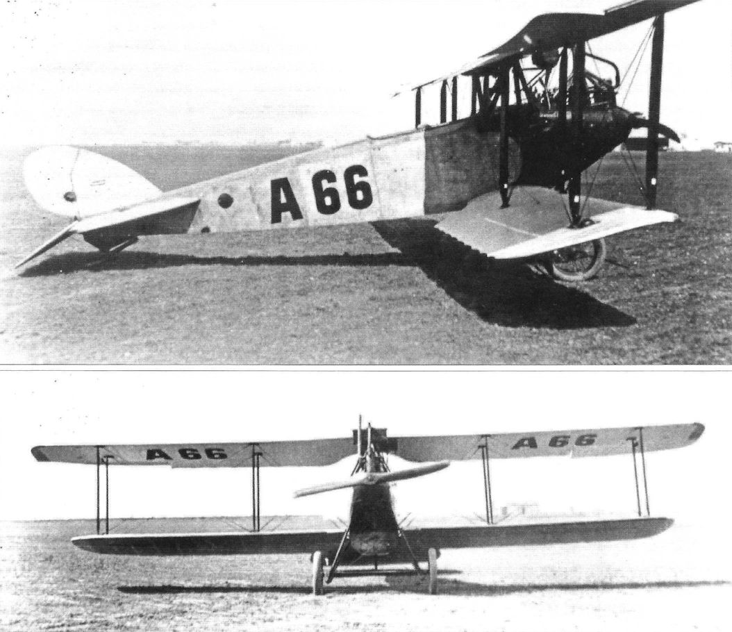
J.Herris - LVG Aircraft of WWI. Volume 2: Types C.II-C.V /Centennial Perspective/ (35)
Two views of a LVG C.V converted to civil use and assigned serial A66 on the postwar Austrian civil registration.
-
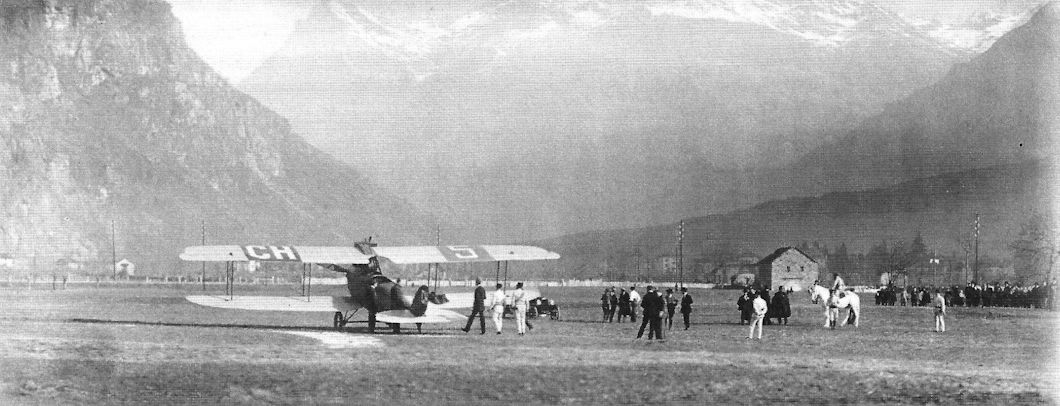
J.Herris - LVG Aircraft of WWI. Volume 2: Types C.II-C.V /Centennial Perspective/ (35)
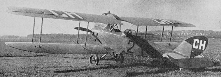
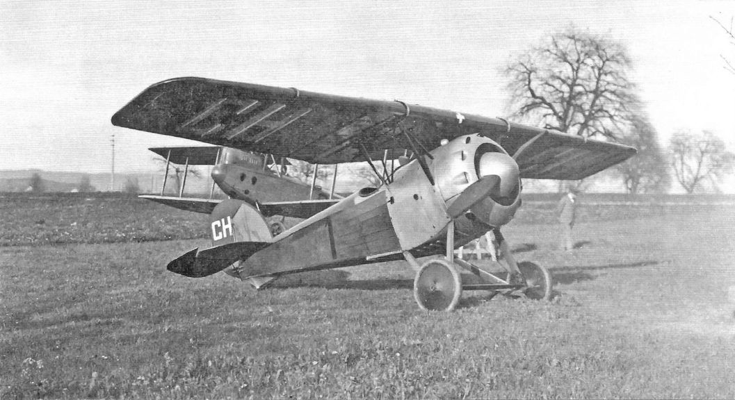
Postwar view of LVG C.V aircraft on the civil register in Switzerland. The aircraft is registered CH-5
-

J.Stroud - European Transport Aircraft since 1910 /Putnam/
This L.V.G. C V was used by Ad Astra Aero and bore the second Swiss civil registration, CH 2.
-
J.Herris - LVG Aircraft of WWI. Volume 2: Types C.II-C.V /Centennial Perspective/ (35)
Postwar view of LVG C.V aircraft on the civil register in Switzerland. The code may be CH-2 or CH-3.
-
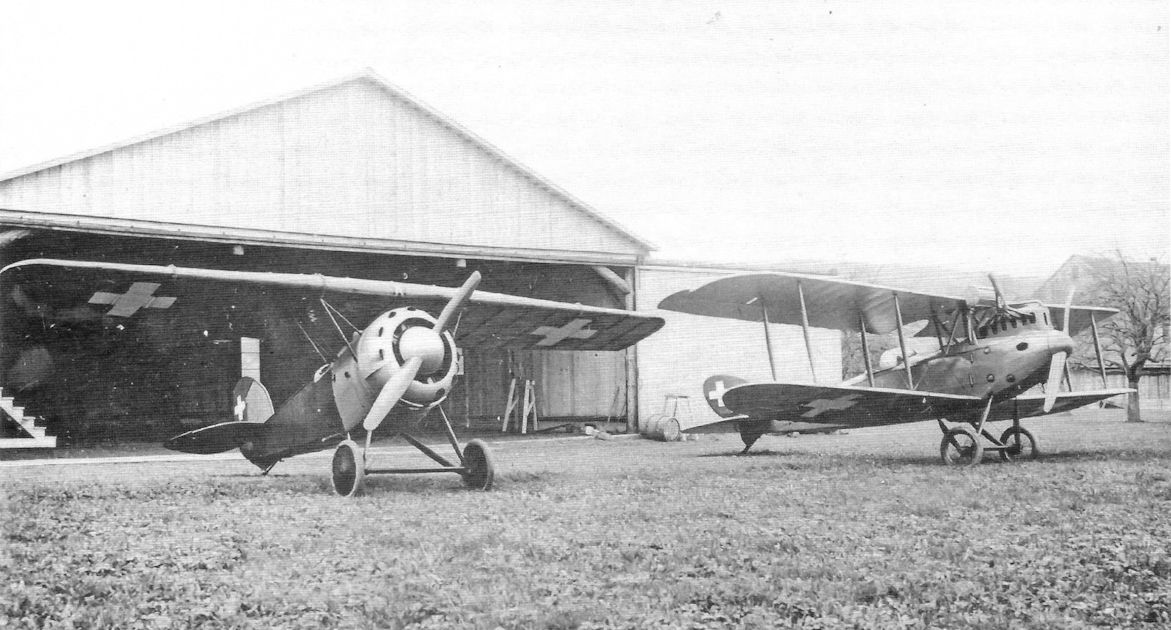
J.Herris - German Aircraft of Minor Manufacturers in WW1. Volume I /Centennial Perspective/ (49)
This Kondor E.IIIa was photographed in 1919 in Switzerland, it was owned by the Comte, Mittleholzer & Co. (Aero Gesellschaft). An LVG C.V in Swiss markings is at right.
Другие самолёты на фотографии: Kondor E.3 / D.I - Германия - 1918
-

J.Herris - German Aircraft of Minor Manufacturers in WW1. Volume I /Centennial Perspective/ (49)
The Kondor E.IIIa was powered by the 160 hp Goebel Goe.III rotary and had a spinner and full cowl. The Kondor E.III was powered by the 160hp Oberursel Ur.III rotary and had a cutaway cowl and no spinner. This aircraft was photographed in 1919 in Switzerland, where it was employed for aerobatic displays. An LVG C.V is in the background.
Другие самолёты на фотографии: Kondor E.3 / D.I - Германия - 1918
-
J.Herris - LVG Aircraft of WWI. Volume 2: Types C.II-C.V /Centennial Perspective/ (35)
A modified Latvian LVG C.V with under-fuselage radiator replacing the usual leading edge radiator picking up a message at an air show in 1935. The Latvian insignia was a red Swastika on a white circle at this time.
-

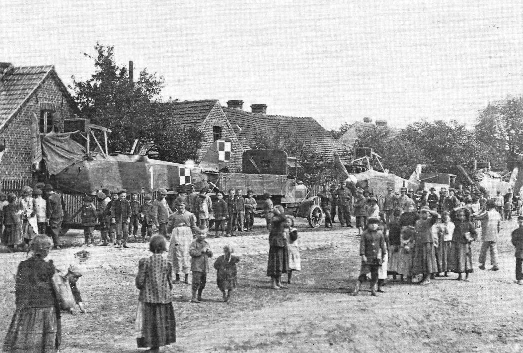
M.Kabatek, Fr.R.Kulczynski - German Aircraft in Polish Service. Volume 1 /Aeronaut/
Inside the airship hangar in Poznan. At the time of the photo, on 15 March 1920, there were more than 200 German aircraft in it, including the AEG C.IV, AEG N.I, Albatros B.II, Albatros J.I and LVG C.V biplanes. (Arkadiusz Kalinski)
Другие самолёты на фотографии: AEG C.IV/C.IVA/C.V/C.VI - Германия - 1916AEG N.I / C.IV N - Германия - 1917Albatros B.II - Германия - 1914Albatros J.I - Германия - 1917
-

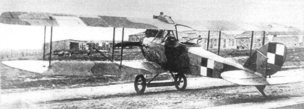
J.Herris - LVG Aircraft of WWI. Volume 3: Types C.VI-C.XI & Fighters /Centennial Perspective/ (36)
LVG C.V Polish no. 211/17 from 3rd Eskadra Wielkopolska. Aircraft mounted in Poznan Lawica with interesting three tone green, brown, and yellowish sand camouflage.
-

M.Kabatek, Fr.R.Kulczynski - German Aircraft in Polish Service. Volume 1 /Aeronaut/
Aircraft of the III Esk. Wlkp.: LVG C.V (211/17) and Halberstadt Cl.II (Bay) 781/18 behind it. Location: Gora, June 1919. (Biblioteka Uniwersytecka w Poznaniu)
Другие самолёты на фотографии: Halberstadt CL.II/CL.IIa - Германия - 1917
-

A.Olejko - War Wings Over Galicia 1918-1919 /Aeronaut/
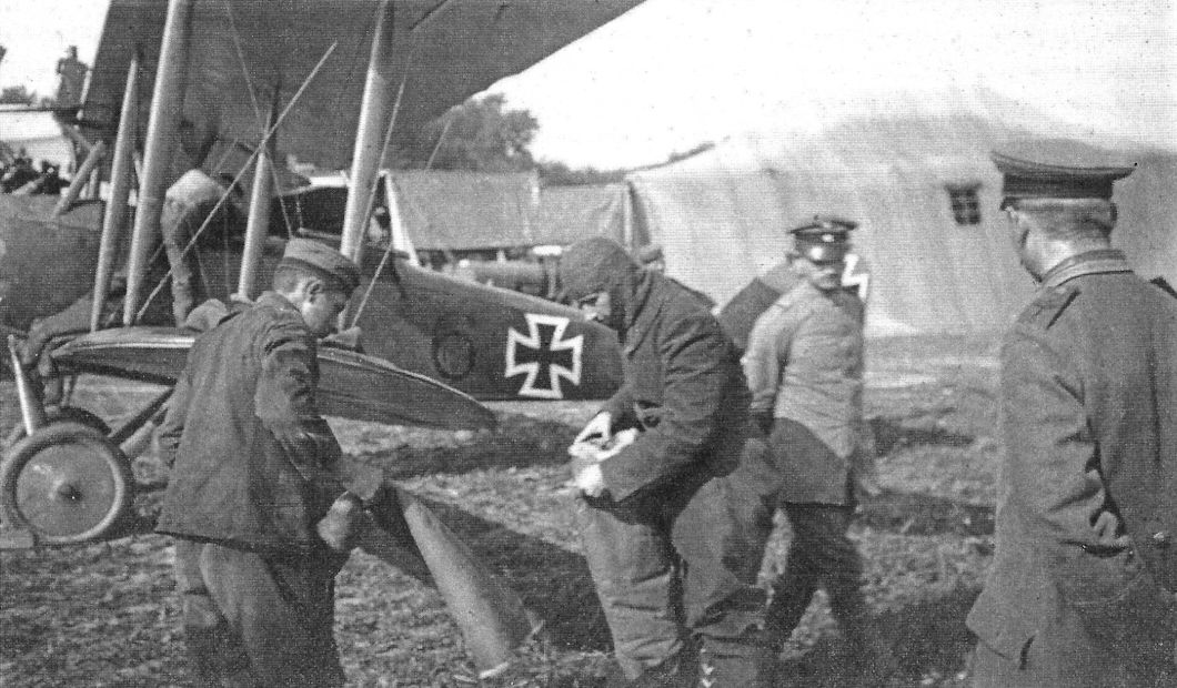
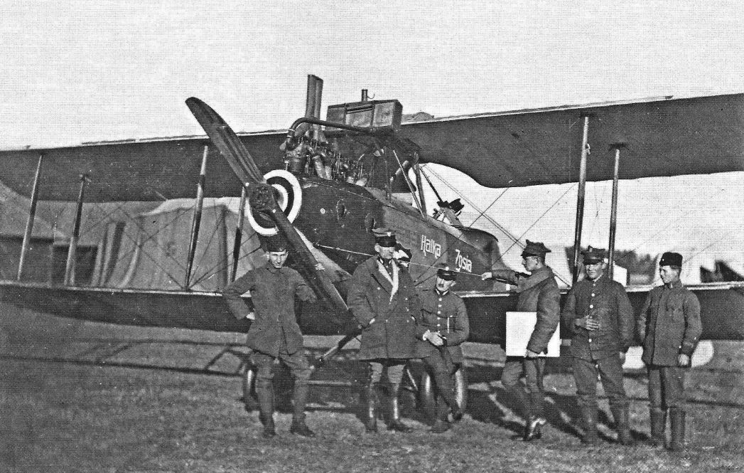
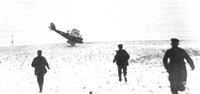
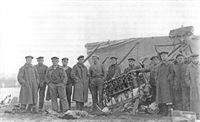
Winter war on the BeloRussian Front... In 1919, the crews of the 1st Greater Poland Air Squadron, despite the winter weather, were constantly in combat. Loading bomb to LVG C.V, Lulu - Wanda. (collection of the Air Force Museum in Dublin)
-
J.Herris - LVG Aircraft of WWI. Volume 3: Types C.VI-C.XI & Fighters /Centennial Perspective/ (36)
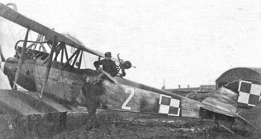
LVG C.V 15917/17 '2' named ‘Stasia' from 1st Eskadra Wielkopolska (Wielkopolan Squadron). The aircraft has two-tone German camouflage. Photo taken in April 1919 at Hureczko near Przemysl airfield, during operation code name ‘Jazda' ('Ride'). Note the two color (red-white) painted propeller spinner. All 1 EW Squadron's aircraft at this time had red-white spinners, some with painted girl's names at white spinner strip. (Piotr Mrozowski)
-

A.Olejko - War Wings Over Galicia 1918-1919 /Aeronaut/
LVG C.V 3201/17 (wk. 30746) '3' named ‘Kotek'. (Piotr Mrozowski)
"Women's Squadron"... The planes of the 1st Greater Poland Air Squadron had female names painted on their fuselages. In the photographs in Galicia and on the Lithuanian-Belarusian Front in 1919 squadron pilots against the background of an LVG C.V aircraft named Mania - Ema (machine 4), Halka - Zosia (machine 5), Stasia (machine 2) and Kotek (machine 3). (collection of the Air Force Museum in Dublin) -
J.Herris - LVG Aircraft of WWI. Volume 3: Types C.VI-C.XI & Fighters /Centennial Perspective/ (36)
LVG C.V 2228/17 (work no. 31122) '4' named 'Mania'/'Ema'. (Piotr Mrozowski)
-

A.Olejko - War Wings Over Galicia 1918-1919 /Aeronaut/
"Women's Squadron"... The planes of the 1st Greater Poland Air Squadron had female names painted on their fuselages. In the photographs in Galicia and on the Lithuanian-Belarusian Front in 1919 squadron pilots against the background of an LVG C.V aircraft named Mania - Ema (machine 4), Halka - Zosia (machine 5), Stasia (machine 2) and Kotek (machine 3). (collection of the Air Force Museum in Dublin)
-

J.Herris - LVG Aircraft of WWI. Volume 3: Types C.VI-C.XI & Fighters /Centennial Perspective/ (36)
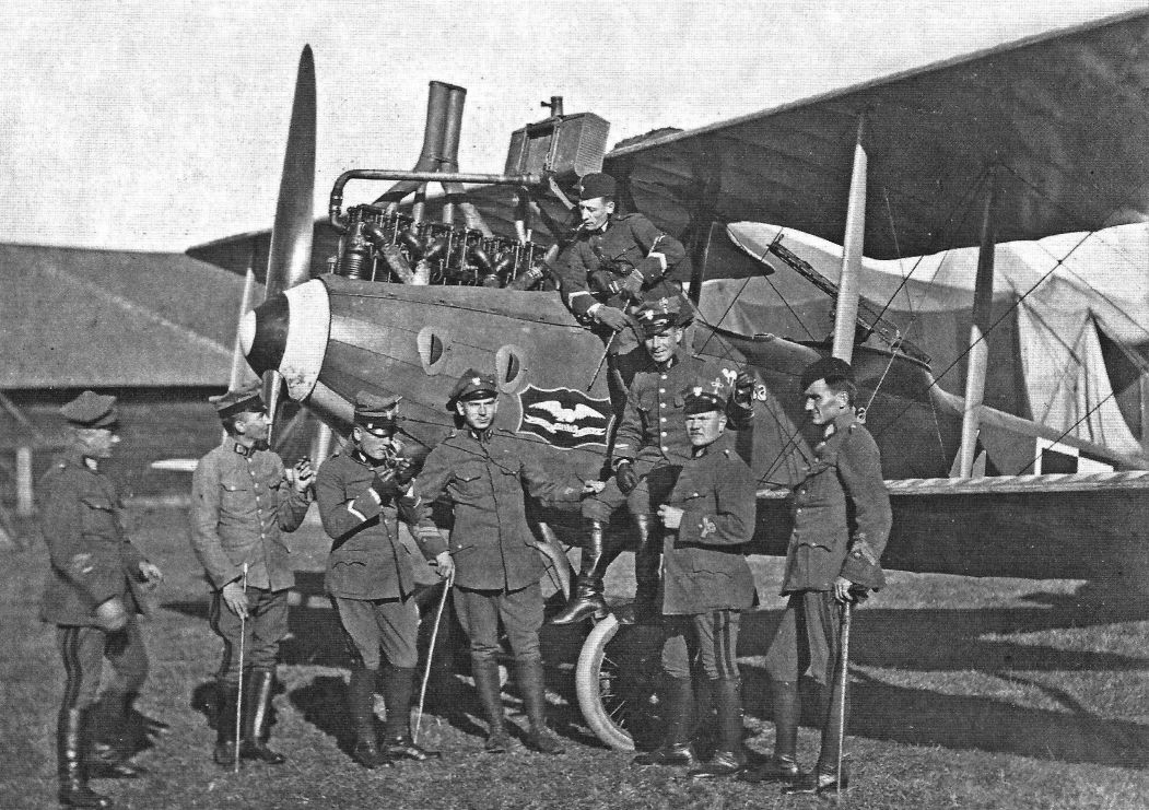
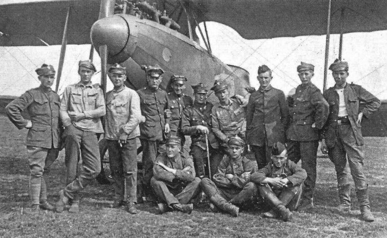
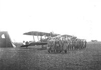
Group of 12 Eskadra Wywiadowcza pilots and observers, photographed near LVG C.V 2228/17 '4' Mania/Ema at Kalenkowicze near Bobrujsk airfield in September 1919. From left observer sergeant Roman Swiecicki, pilot sergeant Kazimierz Burzynski, pilot Lt. Franciszek Jach, pilot sergeant Jozef MuhInikiel, observer Lt. Bogdan Baczynski, observer Lt. Maksymilian Kowalewski, pilot Sergent Boleslaw Gallus, and pilot sergeant Jozef Napierala. Note:The Squadron honor emblem "For defending Eastern Borderlands" (Za Obrone Kresow Wschodnich) painted at the front of aircraft. The aircraft is in violet/green on the top and light blue on the bottom camouflage. (Piotr Mrozowski)
-

J.Herris - LVG Aircraft of WWI. Volume 3: Types C.VI-C.XI & Fighters /Centennial Perspective/ (36)
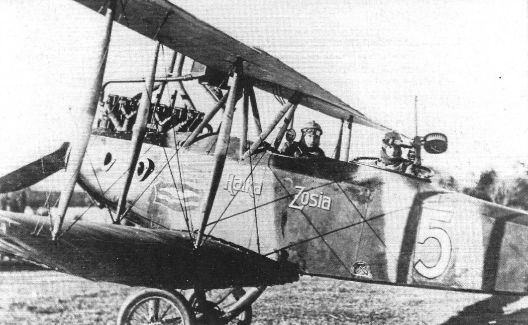
LVG C.V 15948/17 (wk. 33249) '5', from 1st EW (12th reconnaissance squadron). At this time the aircraft has two girls names,'Halka'/'Zosia', painted on the fuselage. The aircraft is still in original German camouflage. (Piotr Mrozowski)
-

A.Olejko - War Wings Over Galicia 1918-1919 /Aeronaut/
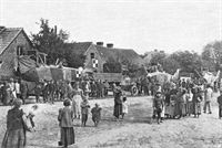
Wide tracks... The Greater Poland Air Force Squadron, like other Polish aviation units, had an iron railway as its basic means of transport. (collections of the Air Force Museum in Dublin)
-
J.Herris - LVG Aircraft of WWI. Volume 3: Types C.VI-C.XI & Fighters /Centennial Perspective/ (36)
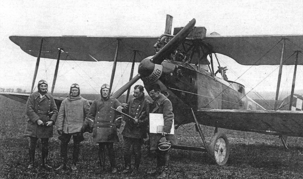
Group of airmen from 1 st Eskadra Wielkopolska (12th EW) just before a combat mission, photographed near LVG C.V 15948/17 (wk 33249) '5' named 'Halka'. Hureczko n/Przemysl airfield, 18 March 1919. Aircraft in original German, two-tone, violet-green camouflage. Note: The girl's name was painted at propeller boss and small CSL (?) logo was painted at nose. The dynamo mount is seen at undercarriage leg. (Piotr Mrozowski)
-

A.Olejko - War Wings Over Galicia 1918-1919 /Aeronaut/
"Women's Squadron"... The planes of the 1st Greater Poland Air Squadron had female names painted on their fuselages. In the photographs in Galicia and on the Lithuanian-Belarusian Front in 1919 squadron pilots against the background of an LVG C.V aircraft named Mania - Ema (machine 4), Halka - Zosia (machine 5), Stasia (machine 2) and Kotek (machine 3). (collection of the Air Force Museum in Dublin)
-
J.Herris - LVG Aircraft of WWI. Volume 3: Types C.VI-C.XI & Fighters /Centennial Perspective/ (36)
LVG C.V 15948/17 (wk. 33249) '5' named 'Halka/Zosia' from 1 st Eskadra Wielkopolska (12th EW). From left: air mechanic Przywarski, pilot Lt. Ludwik Halagiera, pilot Lt. Teofl Krzywik, observer sergeant Leonard Hudzicki, unknown, and air mechanic Waller. Note small white airplane silhouette in circle painted at nose - very probably CSL (Centralna Skladnica Lotnicza - Central Air Depot Warsaw) logo.
-

A.Olejko - War Wings Over Galicia 1918-1919 /Aeronaut/
Golden hands of mechanics... Co-authors of the combat successes of the crews of the 1st Greater Poland Air Squadron in 1919 were its mechanics. In the photographs mechanics at the LVG C.V plane. (collection of the Air Force Museum in Dublin)
-

J.Herris - LVG Aircraft of WWI. Volume 3: Types C.VI-C.XI & Fighters /Centennial Perspective/ (36)
Pilots and mechanics from 12 Eskadra Wywiadowcza photographed at front of the LVG C.V 9.5 aircraft. Siekierki/near Warsaw airfield, August 1920. (Piotr Mrozowski)
-

A.Olejko - War Wings Over Galicia 1918-1919 /Aeronaut/
Polish uniforms, German aircraft... In the photograph of the aviators of the 1st Greater Poland Air Squadron against the background of an LVG C.V aircraft. (collection of Museum of the Air Force in Dublin)
-

A.Olejko - War Wings Over Galicia 1918-1919 /Aeronaut/
Belarus 1920... Guest in the 1st Greater Poland Air Squadron - 12th Reconnaissance Squadron. Squadron staff against the background of LVG C.V plane - inside the squadron commander Captain Wladyslaw Jurgenson and Gen. Daniel Konarzewski commanding the Combined Greater Poland Division. (Air Force Museum)
-

A.Olejko - War Wings Over Galicia 1918-1919 /Aeronaut/
Commemorative photo taken at 1st EW (12 EW) during Gen. Daniel Konarzewski's visit. In the center of flying and ground personnel is guest Gen. D. Konarzewski and Eskadra CO Lt. pilot Wladyslaw Jurgenson. Note interesting unidentified LVG C.V seen at center, with closed fuselage side engine ventilation and partially seen painted girl name 'Milka'. Kisielewicze airfield, April 1919. (Piotr Mrozowski)
-
J.Herris - LVG Aircraft of WWI. Volume 3: Types C.VI-C.XI & Fighters /Centennial Perspective/ (36)
LVG C.V from 8th Reconnaissance Squadron (8. EW). Chelm airfeld, September 1920. The photo was taken during a short break from the action. At this time the squadron was experiencing heavy clashes with the Budionny cavalry. Note the white-red painted spinner.
-

J.Herris - LVG Aircraft of WWI. Volume 3: Types C.VI-C.XI & Fighters /Centennial Perspective/ (36)
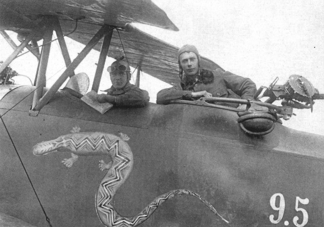
LVG C.V Polish no. 9.5 from 12 Eskadra Wywiadowcza (reconnaissance squadron) with beautiful individual lizard badge. Aircraft from batch of 12th machines mounted in CWL from parts delivered from Poznan in 1920. All aircraft in this batch (CWL no.: 9.1 to 9.12) are adopted to mount an Austro-Daimler (225 hp) engine. Fuselages camouflaged green from the top and blue from bottom, and wings CDL. The crew pilot - Staff Sgt. Antoni Katarzynski and observer Ensign Kazimierz Szczepanski, photographed during the Battle of Warsaw 1920. Note. Observer has a Lewis-Dame machine gun. (Piotr Mrozowski)
-

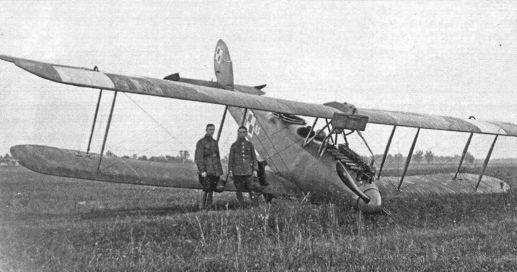
A.Olejko - War Wings Over Galicia 1918-1919 /Aeronaut/
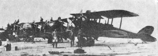
Aviation assistance for Lwow... During the Polish-Ukrainian war of 1918/1919 Krakow-Rakowice airport was the main air base for Polish squadrons fighting in Eastern Galicia and then on the Ukrainian Front. The photo shows the captured Austro-Hungarian and German flying equipment (LVG C.V) of Polish aviation renovated in Krakow workshops in 1919. (collection of the Polish Aviation Museum in Krakow)
-
J.Herris - LVG Aircraft of WWI. Volume 3: Types C.VI-C.XI & Fighters /Centennial Perspective/ (36)
Two LVG C.V from 17 EW. At front machine CWL no. 9.7 (from CWL 9.1 to 9.12 batch), powered with Austro-Daimler engine. Both machines are in CWL green - light blue camouflage.
-
J.Herris - LVG Aircraft of WWI. Volume 3: Types C.VI-C.XI & Fighters /Centennial Perspective/ (36)
LVG C.V 15948/17 '5', with painted girl's name 'Halka' from 1st Field Air Squadron (1-sza Wielkopolska Eskadra). The aircraft is in original German camouflage characteristic for this production batch. Photo taken in Minsk Lit., during changing railways track, from European gauge to Russian standard gauge, which is wider. (Piotr Mrozowski)
-
J.Herris - LVG Aircraft of WWI. Volume 3: Types C.VI-C.XI & Fighters /Centennial Perspective/ (36)
1 st Eskadra Wielkopolska (12th EW) photographed during its move from Wojnowice airfield to the North-East Bolshevik Front, September 1919. From left aircraft LVG C.V 14442/17 (wk. 32544) no '1', next DFW C.V 7897/18 (wk. 33000) no.'2' and LVG C.V no.'5' 15948/17. (Piotr Mrozowski)
Другие самолёты на фотографии: DFW C.V - Германия - 1916
-

J.Herris - LVG Aircraft of WWI. Volume 3: Types C.VI-C.XI & Fighters /Centennial Perspective/ (36)
LVG C.V from 21 st Eskadra Niszczycielska (Destroying Squadron). First from left is pilot Ludomil Rayski, squadron C.O., future commander of the Polish Air Force (1926 to 1939). Aircraft is from the CWL batch.
-

A.Olejko - War Wings Over Galicia 1918-1919 /Aeronaut/
Hureczko and Wojnowice 1919... On the battle route of the 1st Greater Poland Air Squadron in 1919 there was also Eastern Galicia - the airport in Hureczko - and the Belarusian Front - the air gala of the 12th Reconnaissance Squadron at the field airport in Wojnowice. (collection of the Air Force Museum in Dublin)
-
J.Herris - LVG Aircraft of WWI. Volume 2: Types C.II-C.V /Centennial Perspective/ (35)
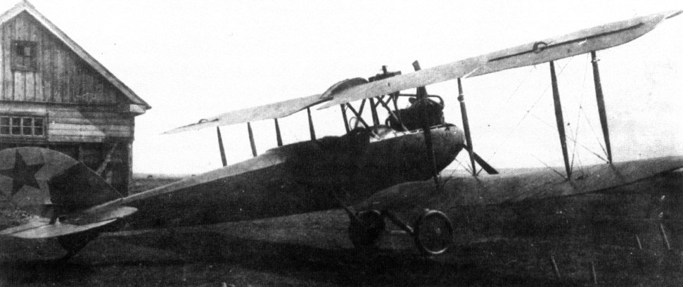
LVG C.V aircraft acquired by Soviet forces and concentrated into a flying unit.
-

H.Nowarra, G.Duval - Russian Civil and Military Aircraft 1884-1969
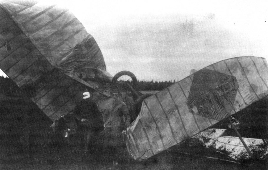
Russian L.V.G. C-Is, Turkestan Front, 1920;
-
H.Nowarra, G.Duval - Russian Civil and Military Aircraft 1884-1969
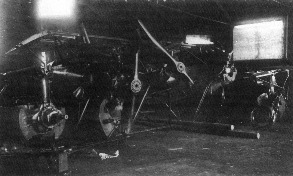
Dismantled L.V.G. C-I;
-
-
-

А.Александров, Г.Петров - Крылатые пленники России
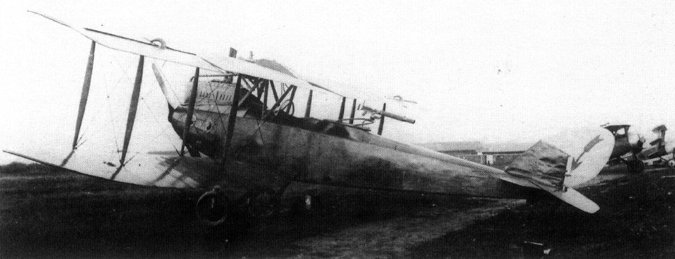
(КПР 66) Several LVG aircraft were obtained by the RKKVF. Below is an LVG C V.
-
-
-
-
-
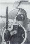
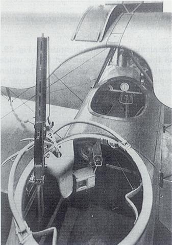
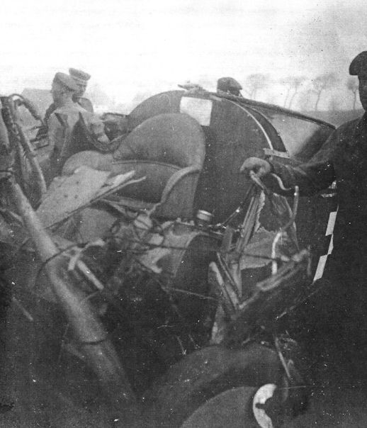
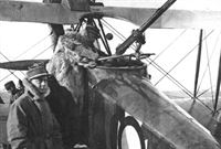
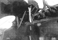
Сайт - Pilots-and-planes /WWW/
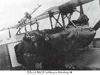
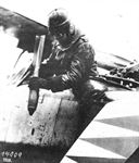
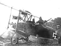
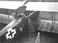
Кабина экипажа самолета CV. В кабине летчика только два прибора и ручка управления в виде трезубца. Пулемет "Парабеллум" установлен на оригинальной турели, напоминающей турель Скарфа, но со своеобразной системой фиксации дуги.
-
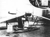
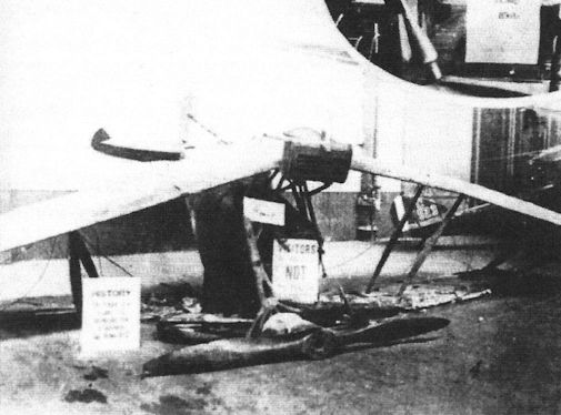
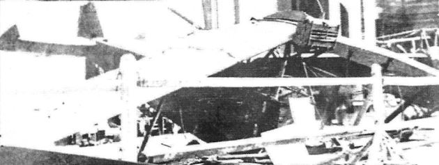
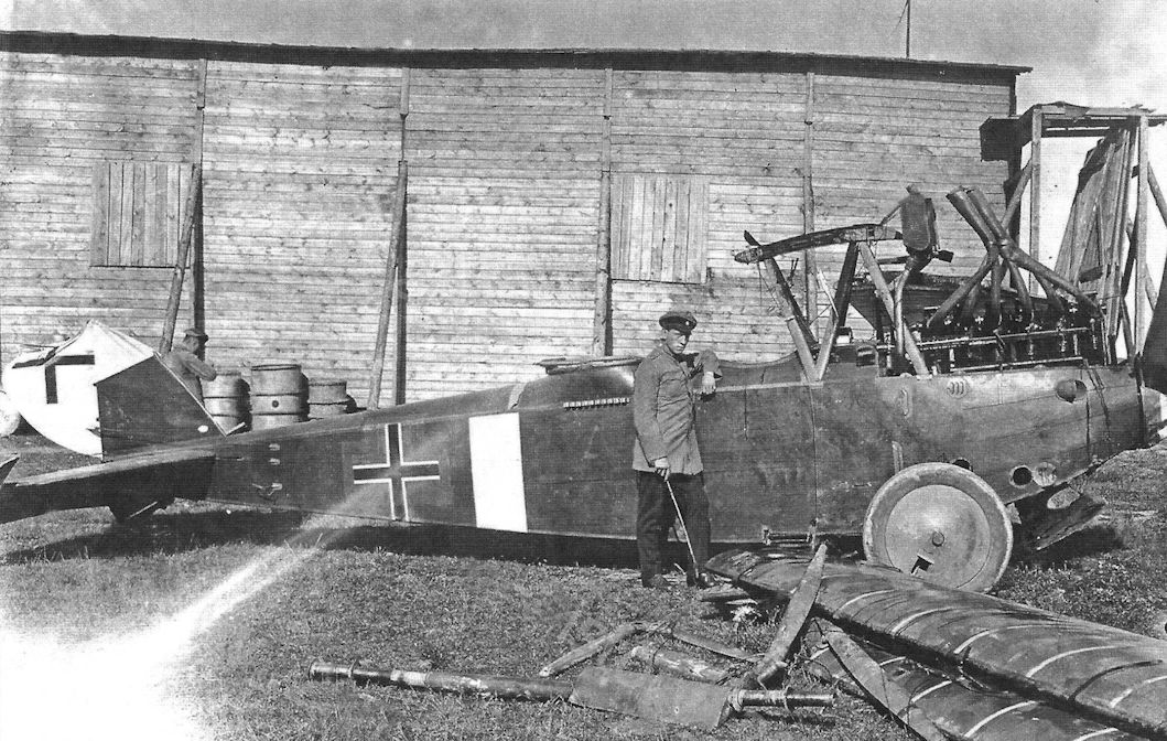
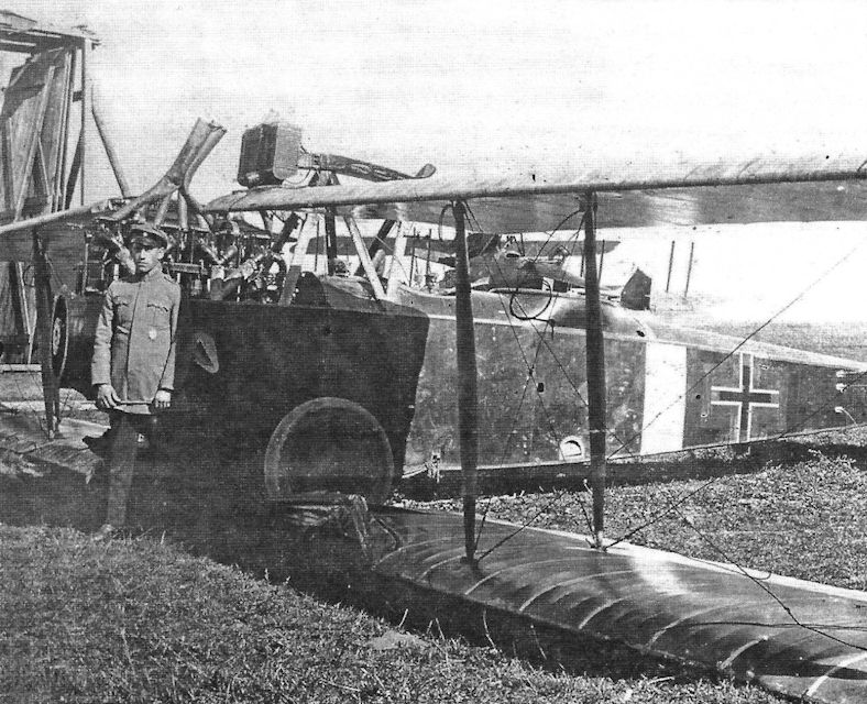
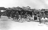
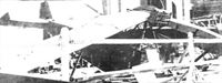
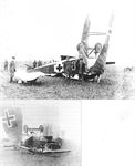
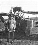
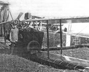
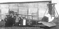
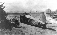
C.Owers - Fokker Aircraft of WWI. Vol.7: Postwar /Centennial Perspective/ (67)
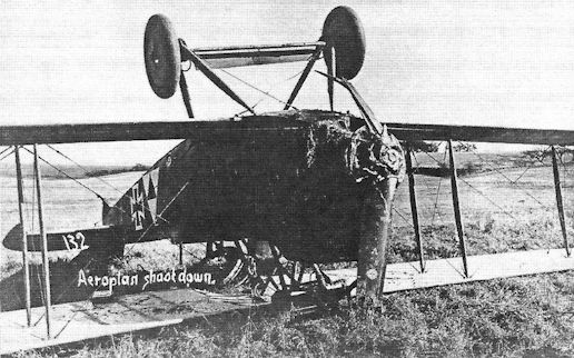
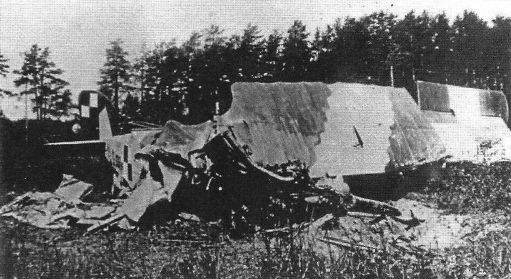
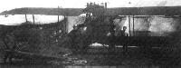
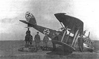
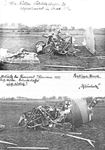
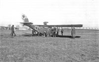
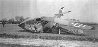
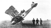
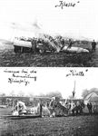
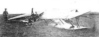
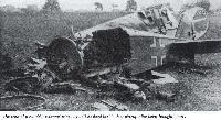
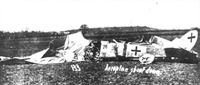
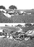
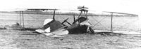
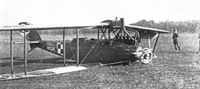
Given the number of people who saw the display of the German aircraft brought back to Australia in the displays in Melbourne. Victoria, and Adelaide, South Australia, the paucity of photographs of these aircraft is hard to understand. This page from The Australasian of 26 June 1920, shows the L.V.G. C.V that was brought down in Palestine and displayed in crashed condition.
-
-
J.Herris - LVG Aircraft of WWI. Volume 2: Types C.II-C.V /Centennial Perspective/ (35)
LVG C.V 3265/17 of FA4 286 after a bad landing. (Bruno Schmaling)
-

J.Herris - LVG Aircraft of WWI. Volume 2: Types C.II-C.V /Centennial Perspective/ (35)
The pilot has wrecked LVG C.V 3269/17 of FAA 279. (Bruno Schmaling)
-
J.Herris - LVG Aircraft of WWI. Volume 2: Types C.II-C.V /Centennial Perspective/ (35)
The pilot of LVG C.V 3301/17 has wiped off the undercarriage in a rough landing. (Reinhard Zankl)
-
J.Herris - LVG Aircraft of WWI. Volume 2: Types C.II-C.V /Centennial Perspective/ (35)
LVG C.V 3335/17 of Schusta 26 completely destroyed in a crash by Uffz. Adam Muller at Thorout in Flanders; he survived. The inscription ‘‘restloser Bruch" indicates a total crash or write-off, and the inscription "Kleinholz" means "kindling" - a description of how smashed up it was. (Bruno Schmaling)
-
J.Herris - LVG Aircraft of WWI. Volume 2: Types C.II-C.V /Centennial Perspective/ (35)
LVG C.V 3342/17 of Schusta 12 after a crash of pilot Kruse and gunner Vogt in Eggen-Capelle. (Greg VanWyngarden)
-
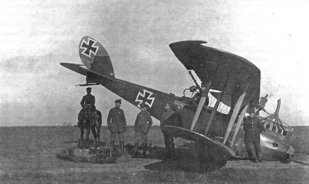
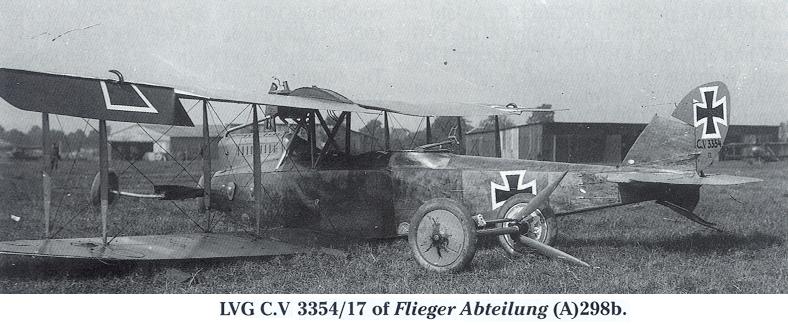
Сайт - Pilots-and-planes /WWW/
LVG C.V 3354/17 of Flieger Abteilung (A) 298b
-
J.Herris - LVG Aircraft of WWI. Volume 2: Types C.II-C.V /Centennial Perspective/ (35)
LVG C.V 4576/17 crashed on 8 November 1917. A white chevron was marked on top of the upper wing and the insignia were marked over white panels, a practice normally abandoned by this time. It is possible that LVG C.V 4576/17 was from Schusta 12. That unit sometimes marked the white square cross fields on their LVG aircraft as sort of a unit marking. The white "chevron" on the top wing is not so much a chevron marking as two white "warning stripes" - if the observer was firing his gun forward over the top wing, he knew not to fire within these two stripes because then his fire might hit the spinning prop.
-
J.Herris - LVG Aircraft of WWI. Volume 2: Types C.II-C.V /Centennial Perspective/ (35)
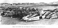
LVG C.V 9740/17 photographed in the postwar aircraft burn pile.
-
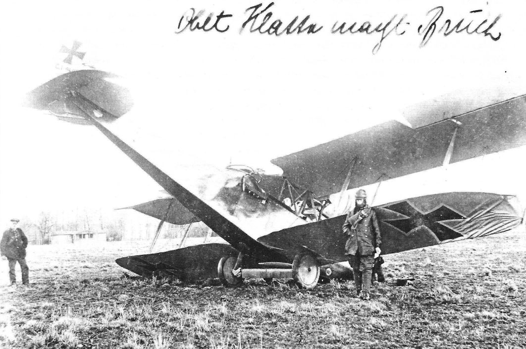
J.Herris - LVG Aircraft of WWI. Volume 2: Types C.II-C.V /Centennial Perspective/ (35)
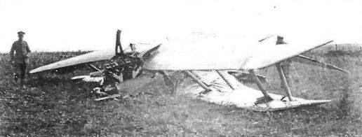
This is Oblt.d.R. Klatte of FA 48b again, having crashed LVG C.V 94XX/17. The caption reads "Oblt. Klatte macht Bruch". (Bruno Schmaling)
-
J.Herris - LVG Aircraft of WWI. Volume 2: Types C.II-C.V /Centennial Perspective/ (35)
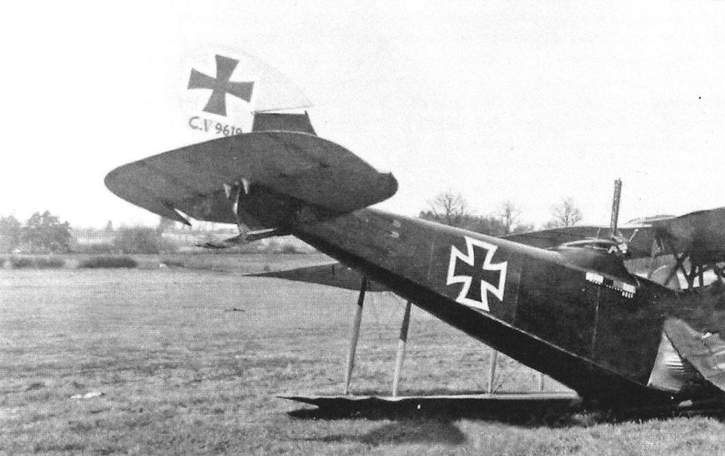
The pilot of LVG C.V 9619/17 has crash-landed it. It appeared in good condition before that. (Reinhard Zankl)
-

J.Herris - LVG Aircraft of WWI. Volume 2: Types C.II-C.V /Centennial Perspective/ (35)
LVG C.V 9619/17 after a bad landing. (Greg VanWyngarden)
-
J.Herris - LVG Aircraft of WWI. Volume 2: Types C.II-C.V /Centennial Perspective/ (35)
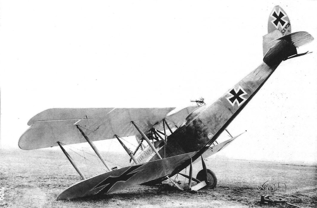
LVG C.V 9707/17 on its nose after a bad landing.
-

J.Herris - LVG Aircraft of WWI. Volume 2: Types C.II-C.V /Centennial Perspective/ (35)
LVG C.V 9728/17 on its nose. (Greg VanWyngarden)
-
J.Herris - LVG Aircraft of WWI. Volume 2: Types C.II-C.V /Centennial Perspective/ (35)
LVG C.V 9828/17 of Flieger-Abteilung (A) 199b. (Greg VanWyngarden)
-
J.Herris - LVG Aircraft of WWI. Volume 2: Types C.II-C.V /Centennial Perspective/ (35)
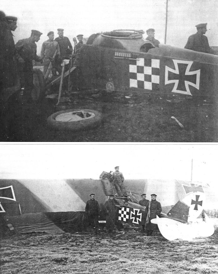
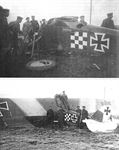
LVG C.V 9868/17 of Marine Schusta II was crashed on 21 March 1918 by Flgmt. Fritz Kirsten (pilot), and gunner Stegemann. Note the checkerboard marking. (Greg VanWyngarden)
-
J.Herris - LVG Aircraft of WWI. Volume 2: Types C.II-C.V /Centennial Perspective/ (35)
Close-up of the cockpit of LVG C.V 9868/17 of Marine Schusta 1 or II crashed 21 March, 1918. The pilot was Flgmt. Fritz Kirsten and the gunner was Stegemann. (Greg VanWyngarden)
-
J.Herris - LVG Aircraft of WWI. Volume 2: Types C.II-C.V /Centennial Perspective/ (35)
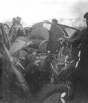
LVG C.V 9868/17 of Marine Schusta II was crashed on 21 March 1918 by Flgmt. Fritz Kirsten (pilot), and gunner Stegemann. The engine has fallen out of the airframe. (Greg VanWyngarden)
-
J.Herris - LVG Aircraft of WWI. Volume 2: Types C.II-C.V /Centennial Perspective/ (35)
LVG C.V 14579/17 of Marine Schusta II after a bad landing. The crew was Fz.Ob.Mtr. Lowenstein and Fz.Ob.Mtr. Hubner. (Greg VanWyngarden)
-
J.Herris - LVG Aircraft of WWI. Volume 2: Types C.II-C.V /Centennial Perspective/ (35)
LVG C.V (possibly 14579/17) of Marine Schusta II after a crash in May 1918. The crew was Loewenstein and Hubner. (Greg VanWyngarden)
-
J.Herris - LVG Aircraft of WWI. Volume 2: Types C.II-C.V /Centennial Perspective/ (35)
LVG C.V 15898/17 after a rough landing. (Greg VanWyngarden)
-
J.Herris - LVG Aircraft of WWI. Volume 2: Types C.II-C.V /Centennial Perspective/ (35)
LVG C.V that has survives extensive battle damage. (Greg VanWyngarden)
-
J.Herris - LVG Aircraft of WWI. Volume 2: Types C.II-C.V /Centennial Perspective/ (35)
The crew of an unidentified LVG C.V is photographed in a head stand; the ground crew who has to fix it is also included. The aircraft wears early 1918 insignia and the Wurttemberg crest on the fuselage.
-

J.Herris - LVG Aircraft of WWI. Volume 2: Types C.II-C.V /Centennial Perspective/ (35)
The crew of an LVG C.V tactical number '6' of FA(A) 238 pose in it after they have wrecked it on landing. They are nonchalant now but the ride from touch down to this must have been much more exciting than they are letting on. (Greg VanWyngarden)
-
J.Herris - LVG Aircraft of WWI. Volume 2: Types C.II-C.V /Centennial Perspective/ (35)
LVG C.V that came down behind Allied lines and was captured. It has an interesting fuselage marking.
-
J.Herris - LVG Aircraft of WWI. Volume 2: Types C.II-C.V /Centennial Perspective/ (35)
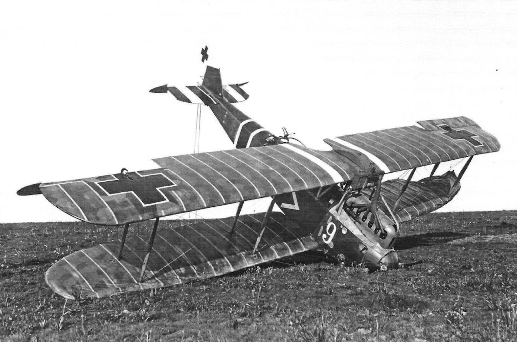
This spectacularly marked LVG C.V bears all the typical unit and personal markings of Bavarian Schlasta 27. By this time, Schlasta 27b was a verstarkt Staffel (strengthened Staffel) with 9 aircraft instead of the previous six usually associated with a Schlasta. Thus, the number "9" on the nose. (Peter M. Grosz Collection/SDTB)
-
J.Herris - LVG Aircraft of WWI. Volume 2: Types C.II-C.V /Centennial Perspective/ (35)
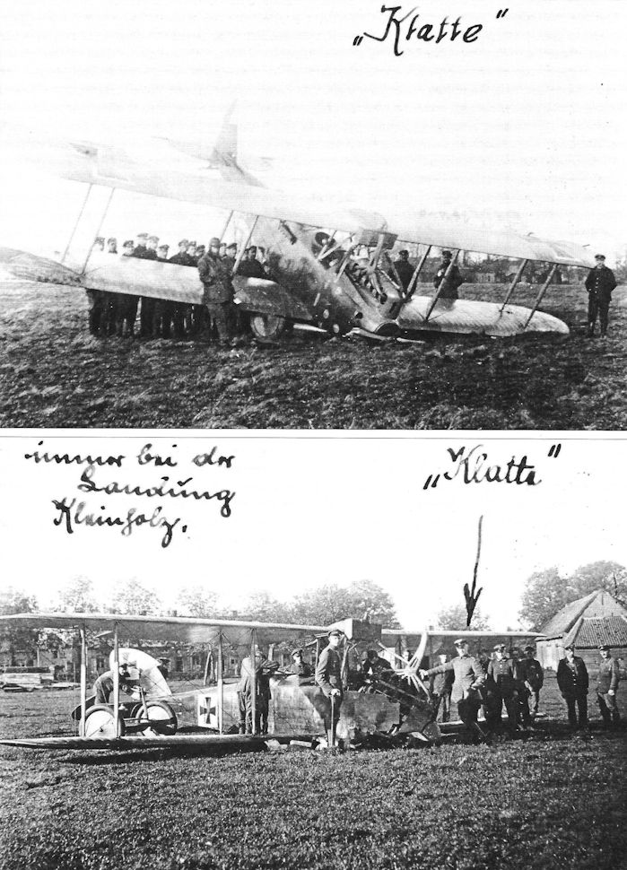
Crash of an unidentified LVG C.V of FA 48. Both photos refer to Klatte. The caption "immer bei der Landung Kleinholz" seems to indicate that Klatte often reduced his aircraft to kindling during landings. (Bruno Schmaling)
-
J.Herris - LVG Aircraft of WWI. Volume 2: Types C.II-C.V /Centennial Perspective/ (35)
LVG C.V after a bad landing. The pensive pilot is leaning against the spinner. (Greg VanWyngarden)
-
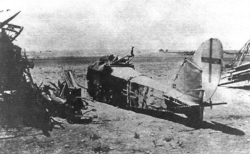
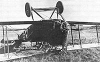
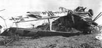
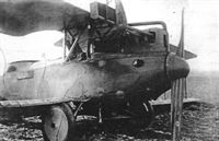
J.Herris - LVG Aircraft of WWI. Volume 2: Types C.II-C.V /Centennial Perspective/ (35)
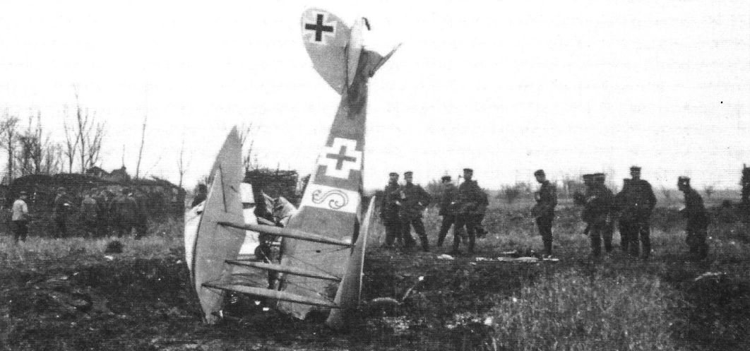
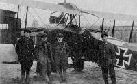
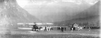
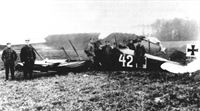
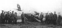
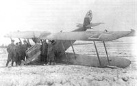
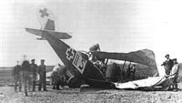
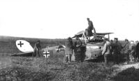
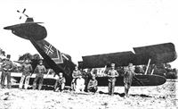
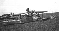
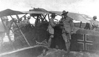
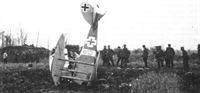
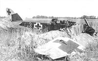
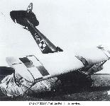
Australian troops surrounds an LVG C.V after being shot down in Palestine.
-
J.Herris - LVG Aircraft of WWI. Volume 2: Types C.II-C.V /Centennial Perspective/ (35)
Crashed LVG C.V with unusual band marking wrapped around the fuselage. (Peter M. Grosz Collection/SDTB)
-
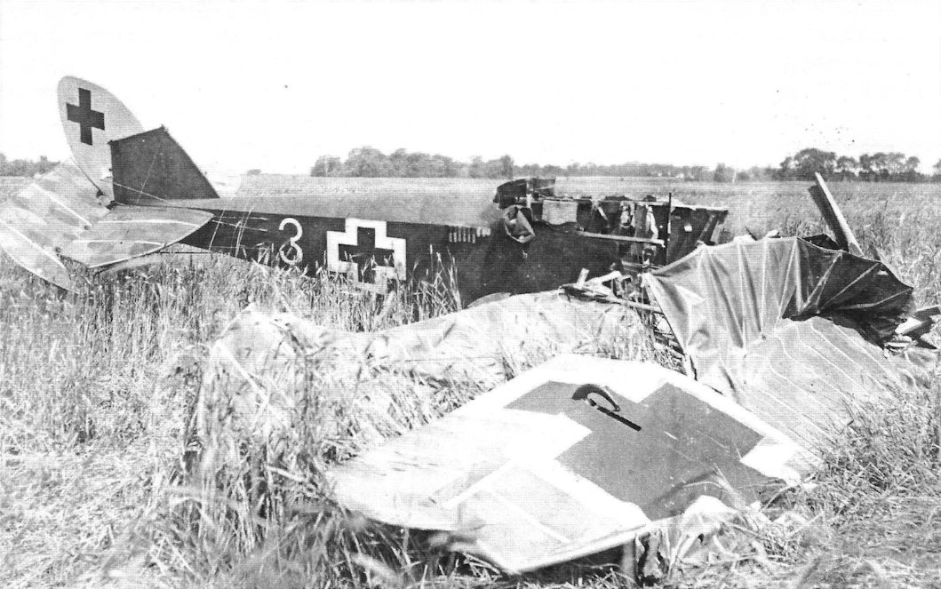
J.Herris - LVG Aircraft of WWI. Volume 2: Types C.II-C.V /Centennial Perspective/ (35)
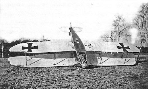
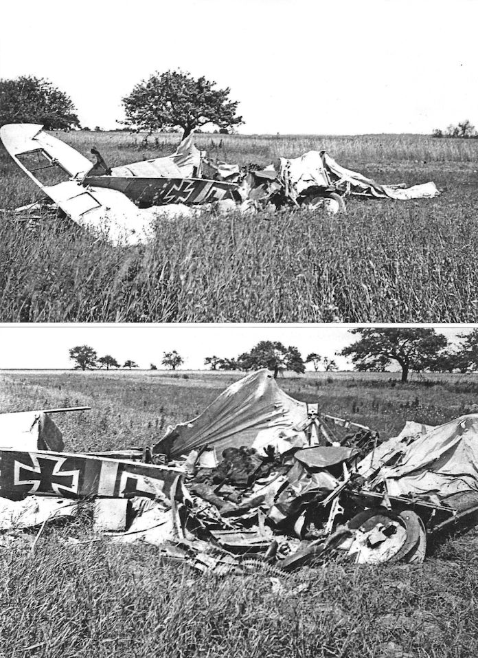
Crash of an unidentified LVG C.V in 1918 insignia after being shot down.
-
J.Herris - LVG Aircraft of WWI. Volume 2: Types C.II-C.V /Centennial Perspective/ (35)
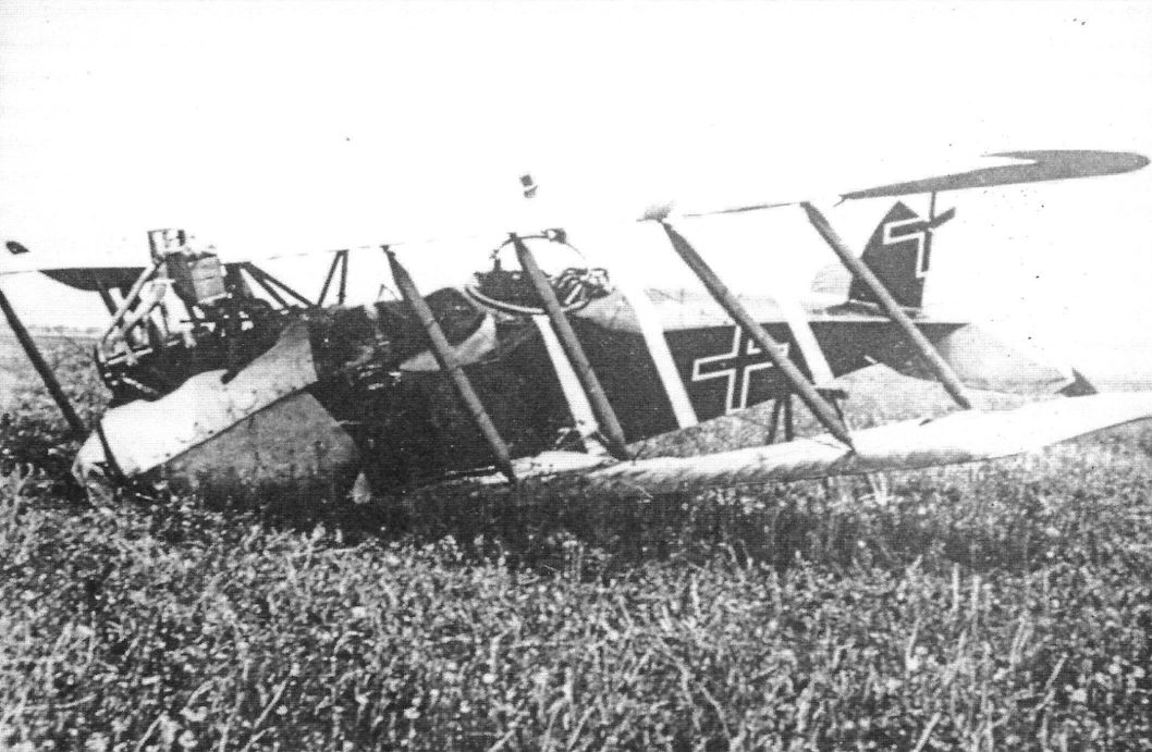
Crashed LVG C.V in early 1918 as shown by the iron cross insignia over-painted to convert them to the new style introduced in March 1918. The stylized 'S' on the fuselage band is a personal marking. (Greg VanWyngarden)
-

J.Herris - LVG Aircraft of WWI. Volume 2: Types C.II-C.V /Centennial Perspective/ (35)
LVG C.V crashed on landing revealing underside detail.
-
J.Herris - LVG Aircraft of WWI. Volume 2: Types C.II-C.V /Centennial Perspective/ (35)
Overturned LVG C.V of Marine Schusta I or II wearing a rat emblem. (Greg VanWyngarden)
-
J.Herris - LVG Aircraft of WWI. Volume 2: Types C.II-C.V /Centennial Perspective/ (35)
LVG C.V tactical number 8 of FAA 286 after a really bad landing. (Bruno Schmaling)
-
J.Herris - LVG Aircraft of WWI. Volume 2: Types C.II-C.V /Centennial Perspective/ (35)
Additional photos of LVG C.V tactical number 8 of FAA 286 after a really bad landing. (Bruno Schmaling)
-
J.Herris - LVG Aircraft of WWI. Volume 2: Types C.II-C.V /Centennial Perspective/ (35)
LVG C.V after being shot down. The insignia on its fuselage appears to be from Flieger Abteilung (A) 209.
-
J.Herris - LVG Aircraft of WWI. Volume 2: Types C.II-C.V /Centennial Perspective/ (35)
LVG C.V of FA 298b crashed on 15 May 1918.
-

J.Herris - LVG Aircraft of WWI. Volume 2: Types C.II-C.V /Centennial Perspective/ (35)
LVG C.V of Marine Schusta II after a crash. The crew was Flugobermatrose Kurt Ortmann and Flgobmtr. Adolf Flink. (Greg VanWyngarden)
-
J.Herris - LVG Aircraft of WWI. Volume 2: Types C.II-C.V /Centennial Perspective/ (35)
LVG C.V downed by Australian machine gunners on 27 September 1917.
-

J.Herris - LVG Aircraft of WWI. Volume 2: Types C.II-C.V /Centennial Perspective/ (35)
Sgt. Heinlein of Flieger-Abteilung (A) 199b with the LVG C.V he crashed. (Greg VanWyngarden)
-
J.Herris - LVG Aircraft of WWI. Volume 2: Types C.II-C.V /Centennial Perspective/ (35)
Sgt. Friedrich Heinlein of Flieger-Abteilung (A) 199b with the LVG C.V he crashed. (Greg VanWyngarden)
-
J.Herris - LVG Aircraft of WWI. Volume 2: Types C.II-C.V /Centennial Perspective/ (35)
Sgt. Friedrich Heinlein of Flieger-Abteilung (A) 199b with the LVG C.V he crashed. (Greg VanWyngarden)
-
J.Herris - LVG Aircraft of WWI. Volume 2: Types C.II-C.V /Centennial Perspective/ (35)
Sgt. Heinlein of Flieger-Abteilung (A) 199b with the LVG C.V he crashed. (Greg VanWyngarden)
-
J.Herris - LVG Aircraft of WWI. Volume 2: Types C.II-C.V /Centennial Perspective/ (35)
Derelict LVG C.V fuselage.
-
J.Herris - LVG Aircraft of WWI. Volume 2: Types C.II-C.V /Centennial Perspective/ (35)
Crashed LVG C.V tactical number 3 of an unidentified unit. (Greg VanWyngarden)
-
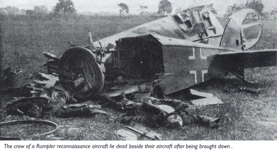
Сайт - Pilots-and-planes /WWW/
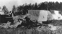
The crew of a Rumpler (???) reconnaissance aircraft lie dead beside their aircraft after being brought down.
-
J.Herris - LVG Aircraft of WWI. Volume 2: Types C.II-C.V /Centennial Perspective/ (35)
Unidentified LVG C.V after being shot down.
-
J.Herris - LVG Aircraft of WWI. Volume 2: Types C.II-C.V /Centennial Perspective/ (35)
LVG C.V downed 24 July 1918 in French lines at Sauvillers-Mongival. (Greg VanWyngarden)
-
J.Herris - LVG Aircraft of WWI. Volume 2: Types C.II-C.V /Centennial Perspective/ (35)
Postwar crash of an LVG C.V modified with an over-wing gun. The C.V was being operated by the Ukraine.
-

J.Herris - LVG Aircraft of WWI. Volume 3: Types C.VI-C.XI & Fighters /Centennial Perspective/ (36)
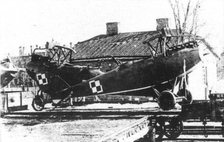
LVG C.V Polish CWL no. 9.5 photographed after crash. Note: No lizard painted at right side and upper wings replaced after cannibalized from another machine (very probably after combat damage) with two-tone German camouflage.
-

J.Herris - LVG Aircraft of WWI. Volume 3: Types C.VI-C.XI & Fighters /Centennial Perspective/ (36)
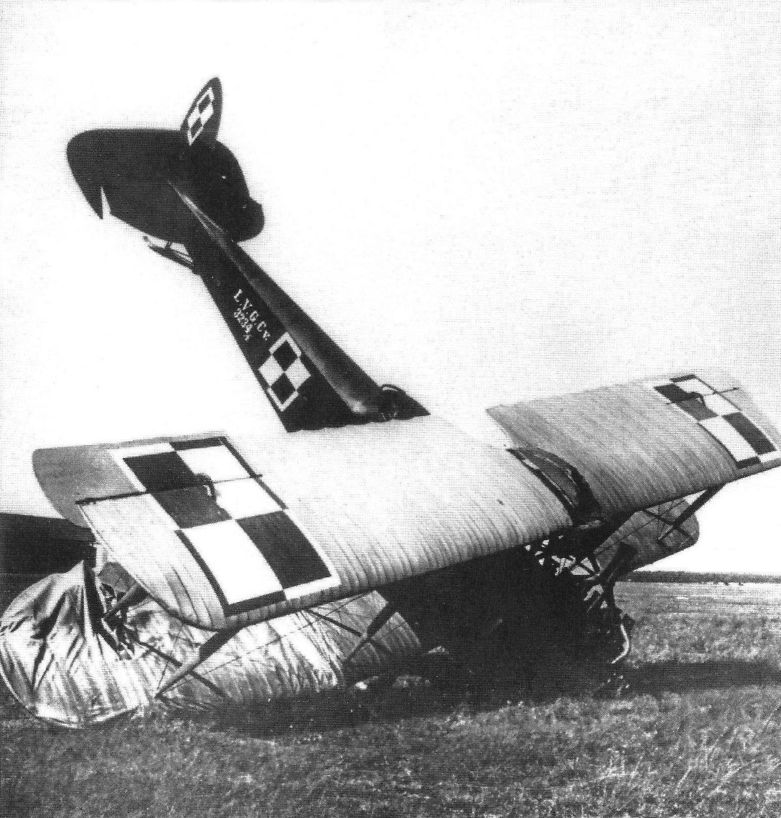
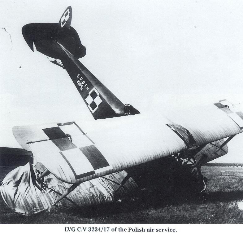
Crashed LVG C.V 3234/17 from OSOL Torun (Ofcerska Szkola Obserwatorow Lotniczych - Air Observers Officers' School). The aircraft is in early Polish camouflage, green fuselage with white stencils, wings clear-doped linen.
-
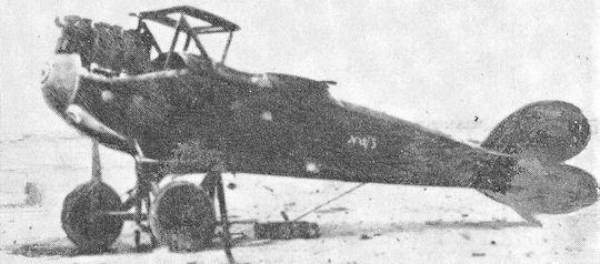
Сайт - Pilots-and-planes /WWW/
LVG C.V 3234/17 of the Polish air service.
-
Сайт - Pilots-and-planes /WWW/
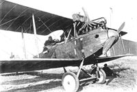
Crashed LVG C.V 4576/17 powered by an 225 hp Austro-Daimler engine.
-
Сайт - Pilots-and-planes /WWW/
Crashed LVG C.V 4576/17 powered by an 225 hp Austro-Daimler engine.
-

J.Herris - LVG Aircraft of WWI. Volume 3: Types C.VI-C.XI & Fighters /Centennial Perspective/ (36)
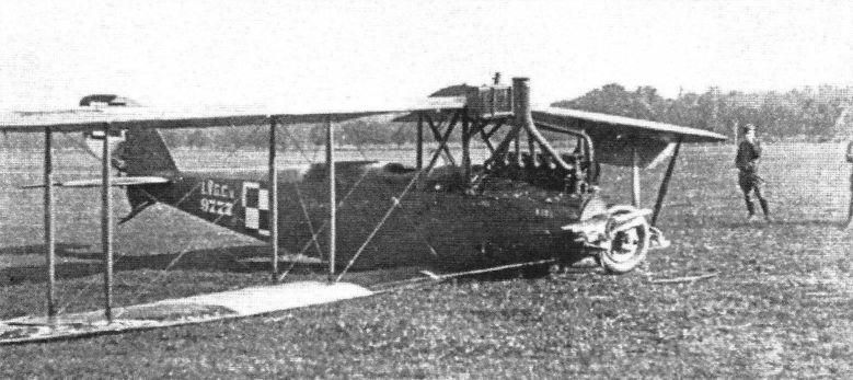
LVG C.V 9495/18 mounted at III RPL Lwow (3rd aircraft depot at Lwow) in characteristic camouflage and markings for machines mounted/repaired in this depot. Fuselage dark olive-green (using ex A-H paint) and wings CDL.
-

J.Herris - LVG Aircraft of WWI. Volume 3: Types C.VI-C.XI & Fighters /Centennial Perspective/ (36)
Crashed LVG C.V Polish no. 211/17 from 3rd Eskadra Wielkopolska. The aircraft mounted in Poznan Lawica with interesting three tone green, brown, and yellowish (sand) camouflage. Note: “Stacja Lotnicza Poznan
Lawica. Tel. 425" information was painted in front of the fuselage chessboard. (Piotr Mrozowski) -

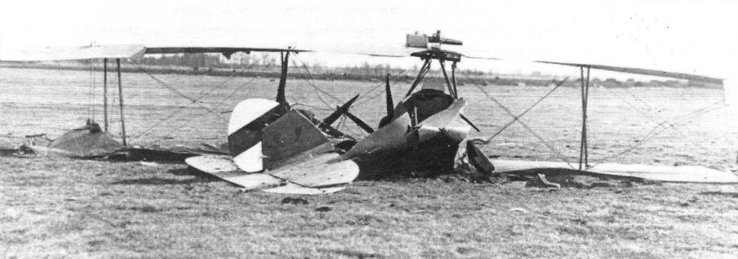
A.Olejko - War Wings Over Galicia 1918-1919 /Aeronaut/
Airports full of wrecks... In the photos, an LVG C.V (P) crashed in 1919 by Lieutenant Tomaszowicz. (collections of the Polish Aviation Museum in Krakow)
-
J.Herris - LVG Aircraft of WWI. Volume 3: Types C.VI-C.XI & Fighters /Centennial Perspective/ (36)
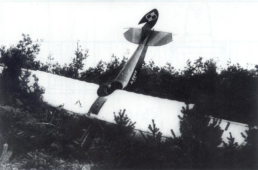
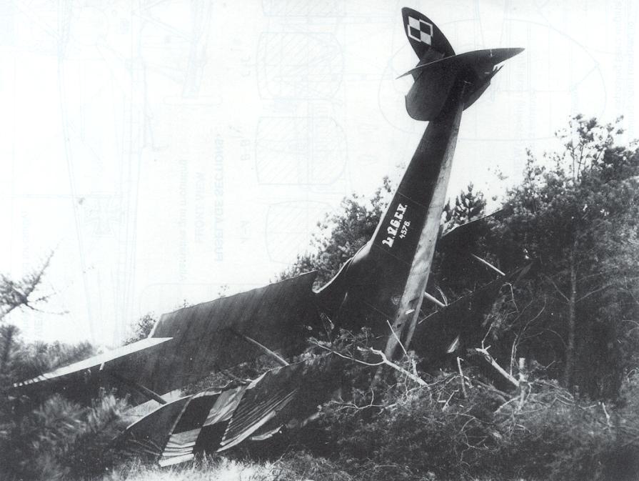
Crashed LVG C.V 9777/17 from the 1st Air Regiment, Warsaw - Mokotowin 1921. The aircraft is in early Polish camouflage: the fuselage is painted green, wings same green patches from the top and CDL from bottom.
-

J.Herris - LVG Aircraft of WWI. Volume 3: Types C.VI-C.XI & Fighters /Centennial Perspective/ (36)
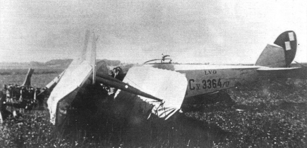
Crashed LVG C.V 3364/17 that belonged to the 14 Eskadra Wywiadowcza. Aircraft was mounted in April 1919 in Poznah/Lawica. Wings camouflaged from top, with large green patches applied by brush straight onto the CDL covering.
-
J.Herris - LVG Aircraft of WWI. Volume 3: Types C.VI-C.XI & Fighters /Centennial Perspective/ (36)
Crashed LVG C.V 3364/17 from 14th Eskadra
-

A.Olejko - War Wings Over Galicia 1918-1919 /Aeronaut/
Front paintings and not only... The front of the Polish-Ukrainian and Polish-Bolshevik wars as well as the airports in the country were strewn with plane wrecks damaged in accidents.
-

A.Olejko - War Wings Over Galicia 1918-1919 /Aeronaut/
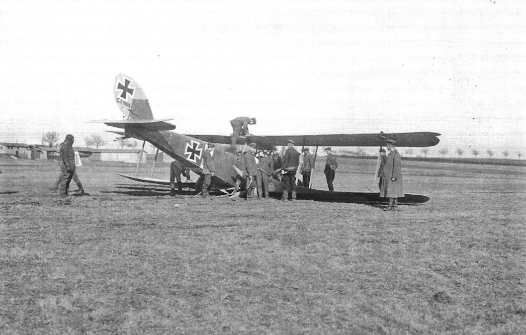
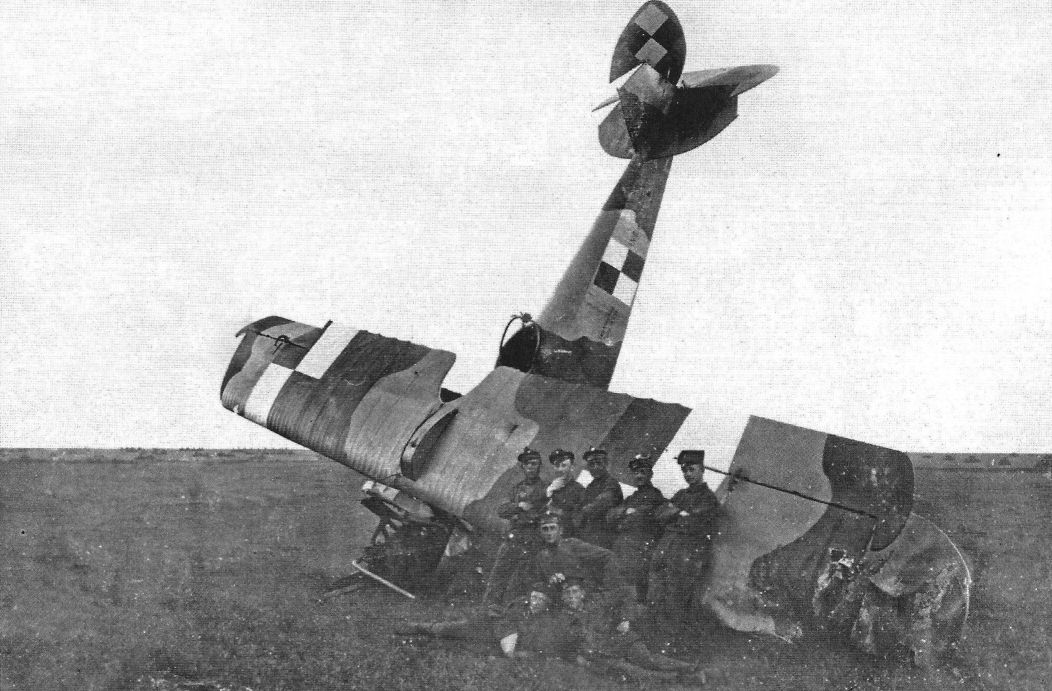
Guest of 1 st Eskadra Wielkopolska (12th EW), Gen. Daniel Konarzewski (with mustache) photographed near Squadron pilots, observers, and mechanics in front of the wreck of LVG C.V 9614/17, Kisielewicze near Bobrujsk airfield, spring 1920. Aircraft was crashed by pilot Lt. Witold Rutkowski. Standing near the fuselage chessboard CO 12 EW Squadron, pilot Lt. Wladyslaw Jurgenson, shot down (10 May 1920), captured, and brutally murdered by Bolsheviks. (Piotr Mrozowski)
-
-

-
J.Herris - LVG Aircraft of WWI. Volume 2: Types C.II-C.V /Centennial Perspective/ (35)
Fred Neumann was the artist for the LVG posters reproduced throughout these volumes.
-
Журнал - Flight за 1918 г.
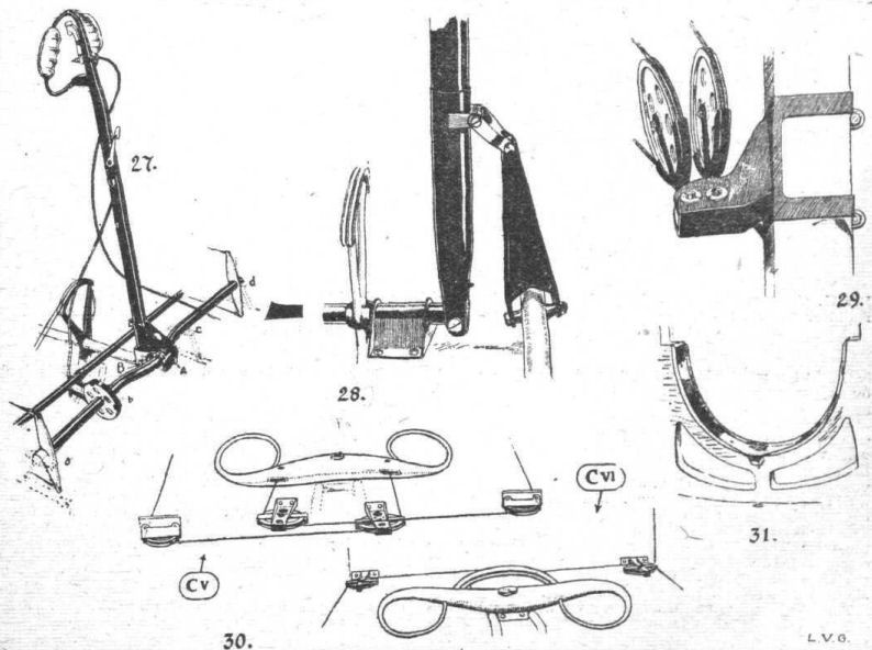
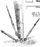
THE L.V.G. C.V. BIPLANE. - Sketch of one of the interplane strut fittings.
-
Журнал - Flight за 1918 г.
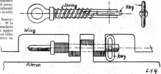
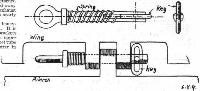
THE L.V.G. C.V. BIPLANE. - The locking hinge-pin for the aileron. The top view shows the pin removed, with the locking key in position for insertion. Below, the pin in position with the key "locked."
-
Журнал - Flight за 1918 г.
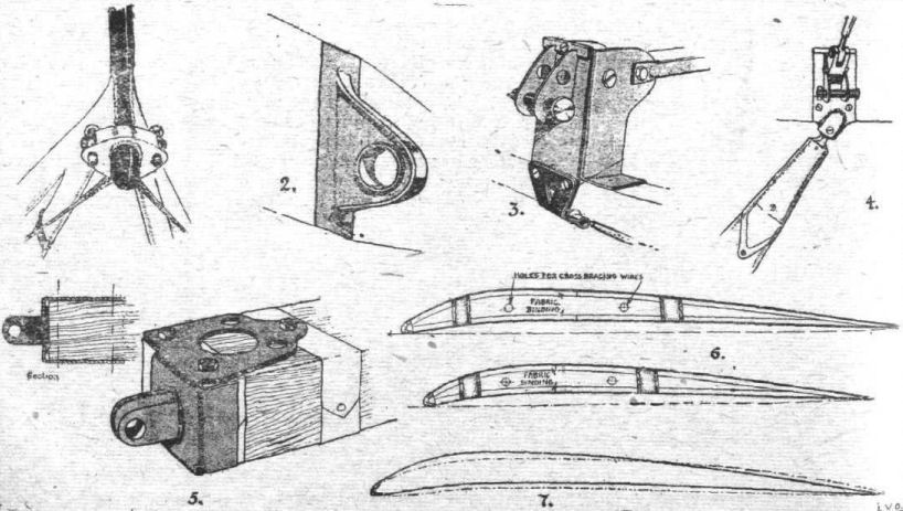
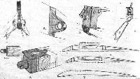
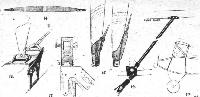
Some L.V.G. Constructional Details. - 1. Spar fitting on cabane of the Type C.V. L.V.G.; 2. Lug on spar engaging with fitting in 1; 3. Bottom front spar Joint; 4. Bottom rear spar joint; 5. Wing spar lug on the C.VI. Type; 6. Upper and lower wing sections of C.VI.; 7. C.VI. upper section with RAF. 14 section superimposed.
Другие самолёты на фотографии: LVG C.VI - Германия - 1918
-
Журнал - Flight за 1918 г.
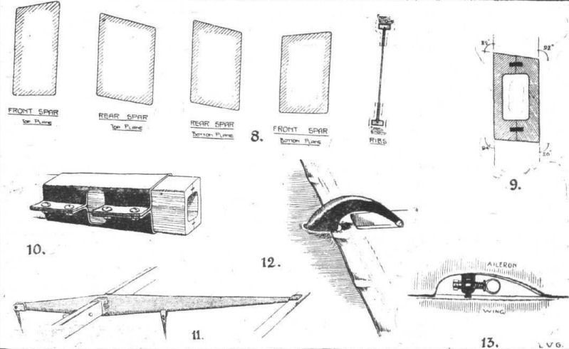
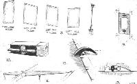
L.V.G. Constructional Details. - 8. C.VI. wing spar sections; 9. Front spar section of C.V.; 10. Field repair of broken spar; 11. Aileron crank of C.VI.; 12, Aileron crank of C.V.; 13. Aileron hinge of both types.
Другие самолёты на фотографии: LVG C.VI - Германия - 1918
-
Журнал - Flight за 1918 г.
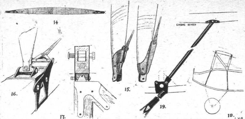
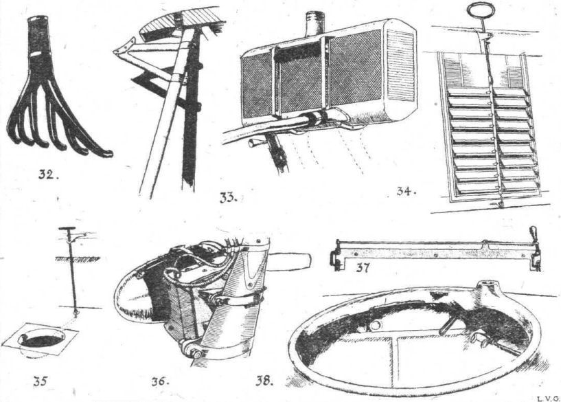
L.V.G. Constructional Details. - 14. C.V. inter-plane strut; 15. C.VI. inter-plane strut socket; 16. Attachment of strut to spar; 17. Attachment of centre section strut to spar on C.VI.; 18. Centre section struts and bulkheads of C.VI.; 19. Bracing tube between rear chassis strut and engine bearer on C.V.
Другие самолёты на фотографии: LVG C.VI - Германия - 1918
-

Журнал - Flight за 1918 г.
L.V.G. Constructional Details. - 20. The bulkheads of the C.V. fuselage; 21. Mounting of the tail plane; 22. Stern of fuselage, showing plywood covering and mounting of tail skids; 23. Protection piece for balanced portion of elevator; 24. Tail skids of the two types.
Другие самолёты на фотографии: LVG C.VI - Германия - 1918
-
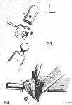
Журнал - Flight за 1918 г.
25 and 26. Undercarriage_details.
Другие самолёты на фотографии: LVG C.VI - Германия - 1918
-
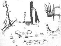
Журнал - Flight за 1918 г.
L.V.G. Constructional Details. - 27. Controls of C.V.; 28. Details of C.VI. controls; 29. Aileron pulleys; 30. Rudder bars of the two types; 31. Aluminium strip protectors of bulkheads against oil.
Другие самолёты на фотографии: LVG C.VI - Германия - 1918
-
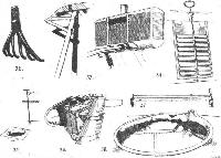
Журнал - Flight за 1918 г.
L.V.G. Constructional Details. - 32. Exhaust pipes of C.VI.; 33. C.V. Radiator supports and radiator; 34, C.VI. radiator shutter; 35. Camera hole and cover of C.V.; 36. Wireless generator mounted on chassis strut of C.VI.; 37. Release gear for unknown object on C.V.; 38. Gun ring of C.VI.
Другие самолёты на фотографии: LVG C.VI - Германия - 1918
-
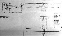
Jane's All The World Aircraft 1919 /Jane's/
L.V.G. Biplane. Type C.V.
-
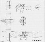
-
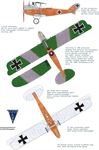
J.Herris - LVG Aircraft of WWI. Volume 2: Types C.II-C.V /Centennial Perspective/ (35)
LVG C.V prod, batch 9400/17 to 9899/17. Trial camouflage reconstruction. January, 2019
-
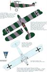
J.Herris - LVG Aircraft of WWI. Volume 2: Types C.II-C.V /Centennial Perspective/ (35)
LVG C.V prod, batches 9400/17 to 9899/17 & 15815/17 to 15964/17 and on LVG C.VI from 1497/18 to 1746/18 batch this camouflage was applied most often. Trial camouflage reconstruction. April, 2019
-
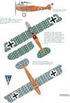
J.Herris - LVG Aircraft of WWI. Volume 2: Types C.II-C.V /Centennial Perspective/ (35)
LVG C.V prod, batch 1750/18 to 1799/18 and some in 15815/17 to 15964/17. Trial camouflage reconstruction. March, 2019
-
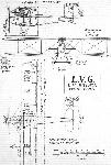
-
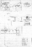
-
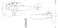
-
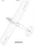
-
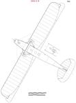
-
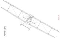
В.Обухович, А.Никифоров Самолеты Первой Мировой войны
Созданный талантливым конструктором Карлом Саберски-Муссигбордт, LVG С V был одним из наиболее удачных немецких двухместных разведывательных самолетов второй половины войны. Он поставлялся в строевые части в течение всего 1917 г. и вполне успешно справлялся с боевыми задачами в качестве легкого бомбардировщика, корректировщика артиллерийского огня и фоторазведчика среднего радиуса действия.
Несмотря на относительно небольшую мощность двигателя, это был достаточно большой самолет. От своего предшественника - разведывательного самолета LVG С II - он отличался увеличенным планером, чистыми аэродинамическими формами и был хорошо скомпонован. Шестицилиндровый рядный двигатель Бенц Bz.IV (200 л. с.) аккуратно вписывался в фюзеляж. Металлические панели капота прикрывали только низ цилиндров, оставляя открытыми головки. Большой оживальныи кок воздушного винта плавно стыковался с капотом. Аэродинамическое сопротивление немного увеличивал фронтальный радиатор, установленный по передней кромке центроплана верхнего крыла (на поздних сериях радиатор был убран в центроплан верхнего крыла). Хвостовое оперение было классическим и напоминало конструкцию "альбатросов". Бипланная коробка имела две пары стоек, нижнее крыло было короче верхнего. Для выработки электроэнергии, используемой для питания радиостанции, применялся генератор с небольшим пропеллером, который размещался на оси шасси.
К осени 1917 г. LVG С V были широко распространены на Западном фронте и пользовались большой популярностью среди летного состава. На начальном этапе боевого применения они несли значительные потери от истребителей противника, но постепенно тактическое мастерство летчиков увеличивалось и экипажи могли достойно постоять за себя. Известный британский ас Маккуден рассказывал, что в одном из боев с двумя С V он в течение пяти минут не мог прицельно атаковать активно оборонявшихся немцев и ему пришлось выйти из схватки, хотя еще месяц назад он легко сбил такой же самолет. Кок от него долгое время красовался в носу истребителя S.E.5, на котором воевал Маккуден.
Всего было произведено около 600 машин LVG С V.
Технические данные LVG С V
Двигатель 1 х Бенц Bz.IV (200 л. с.)
Размеры:
размах х длина х высота 13,62 х 8,07 х 3,05 м
Площадь крыльев 42,7 м2
Вес:
пустого 1013 кг
взлетный 1535 кг
Максимальная скорость 164 км/ч
Скороподъемность 3,0 м/сек
Потолок 5000 м
Дальность 350 км
Вооружение:
стрелковое 1 х 7,92-мм синхронный пулемет "Парабеллум" и
1 х 7,92-мм турельный пулемет "Шпандау"
бомбовое 110 кг
Экипаж 2 чел.
Описание: