А.Шепс Самолеты Первой мировой войны. Страны Антанты
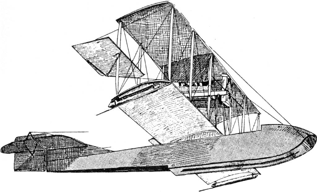
Центральный поплавок самолета А-1 был преобразован в лодочный корпус, и новая машина стала прообразом серии летающих лодок фирмы "Херринг-Кертисс". Все самолеты были однореданными лодками цельнодеревянной конструкции, двух- или трехстоечными бипланами с подкрыльевыми поплавками. Между крыльями на стойках устанавливался 8-цилиндровый, жидкостного охлаждения, рядный, V-образный двигатель "Кертисс" мощностью от 85 до 100л. с. Оперение также имело деревянную конструкцию, обтянутую полотном. В отличие от А-1, оно имело треугольный стабилизатор. Руль поворота имел роговую весовую компенсацию. Машины отличались конструкцией лодки и способом крепления элеронов. Вооружение на них не устанавливалось, и применялись они в основном как разведчики. Экипаж состоял обычно из двух, реже из трех человек.
Здесь, как в серии летающих лодок Д. Л. Григоровича, мы можем наблюдать, как Гленн X. Кертисс методом проб и ошибок вел поиск удачной конструкции, меняя размеры и килеватость лодки, увеличивая или уменьшая размах и площадь крыльев, оперения и элеронов, находясь в поиске лучшего сочетания всех характеристик.
Модификации
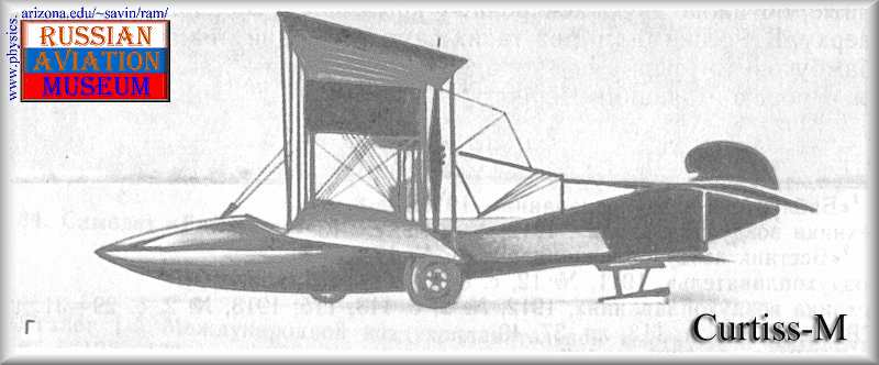
Тип М - двухместный разведчик с элеронами, установленными на стойках между крыльями. Лодка слабокилевая, очень низкая.
Тип К - отличалась большей килеватостью лодки, новой системой подвески элеронов, увеличенной высотой борта.
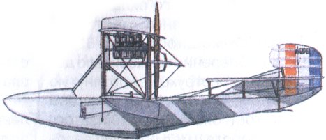
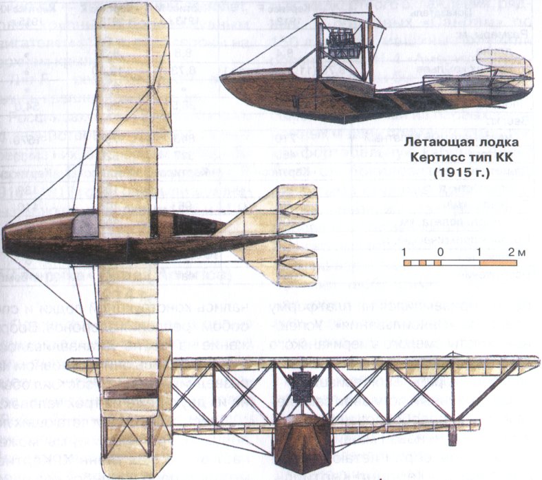
Тип КК - трехместный самолет, более крупный с более мощным двигателем (180л. с.), элероны на верхнем крыле.
Тип F - развитие типа К, отличалась креплением крыльев.
Россия закупила 72 лодки типа М, но задействовать удалось только треть из них, в основном на Черном море в начальный период войны. В 1916-1917 годах они были заменены летающими лодками М-5 и М-9.
Показатель Кертисс F Кертисс М Кертисс К Кертисс КК
1912г. 1913г. 1913г. 1915г.
Размеры, м:
длина 8,4 8,8 8,33
размах крыльев 8,73 8,73 12,50
(11,3 с элерон.)
высота 3,35
Площадь крыла, м2 28,5 28,5 35,12 54,0
Вес, кг:
максимальный взлетный 710 843 798 1570
пустого 460 517 520 1100
Двигатель: "Кертисс" "Кертисс" "Кертисс" "Кертисс"
мощность, л. с. 85 100 180
Скорость, км/ч 75 96 105 110
Дальность полета, км 200 320 300
Потолок практический, м 1700 2000 2000
Экипаж, чел. 2 2 2 3
Вооружение нет нет нет 90 кг бомб
В.Шавров История конструкций самолетов в СССР до 1938 г.
Летающие лодки "Кертис" были трех типов.
"Кертис М". Трехстоечный биплан с элеронами, подвешенными между крыльями, и с двигателем "Кертис" в 80 л. с. Было приобретено 72 самолета, из которых 20 было собрано на Черном море и несколько на Балтийском. Остальные так и не были собраны из-за "плохого качества двигателей". С 17 апреля 1916 г. эти "Кертисы" были заменены отечественными лодками М-5 и М-9.
"Кертис КК" - той же схемы, но крупнее, с двигателем "Кертис-Райт" в 180 л. с., трехместный. Всего в 1915-1916 гг. было шесть экземпляров Самолет летал плохо, очень труден был на нем взлет.
"Кертис Атлантика ( "Аэримарин" ) - двухмоторная летающая лодка, трехместный разведчик Двигатели "Кертис" в 100 л. с. Всего было закуплено 60 лодок, но доставлены в Севастополь только две, из которых одна разбита при сдаче в 1916 г. американским летчиком.
Самолет||/
Год выпуска||1913/1915
Двигатель, марка||/
Мощность, л.с.||85/180
Длина самолета, м||8,8/?
Размах крыла, м||8,73/?
Площадь крыла, м2||28,5/54
Масса пустого, кг||517/1100
Масса топлива+ масла, кг||90/190
Масса полной нагрузки, кг||250/470
Полетная масса, кг||До 843/1570
Удельная нагрузка на крыло, кг/м2||29,5/29
Удельная нагрузка на мощность, кг/лс||10/8,7
Весовая отдача,%||29/30
Скорость максимальная у земли, км/ч||96/110
Скорость посадочная, км/ч||75/75
Время набора высоты||
1000м, мин||20/?
2000м, мин||50/?
Потолок практический, м||2000/?
Продолжительность полета, ч.||3,5/?
P.Bowers Curtiss Aircraft 1907-1947 (Putnam)
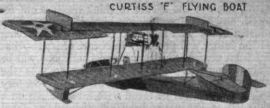
Model F
1913 Model. The 1913 Model F used the early composite hull construction and what were essentially Model E-75 wings with strut-braced extensions of the upper wing. Because of its many 'old' features relative to the 1914 F-boat, the 1913 model has sometimes (and erroneously) been referred to by historians as the E-boat in disregard of the recognized Curtiss Model E landplane and the Navy's E-designation.
Model F (1913)
Two seats.
Span 41 ft 8 in (12.69 m); length 27 ft 4 in (8.33 m).
Gross weight 1,760 lb (798 kg).
Maximum speed 54.8 mph (88.19 km/h); climb 1,200 ft (365 m) in 7.6 min; endurance 4 hr.
Powerplant 75 hp Curtiss O.
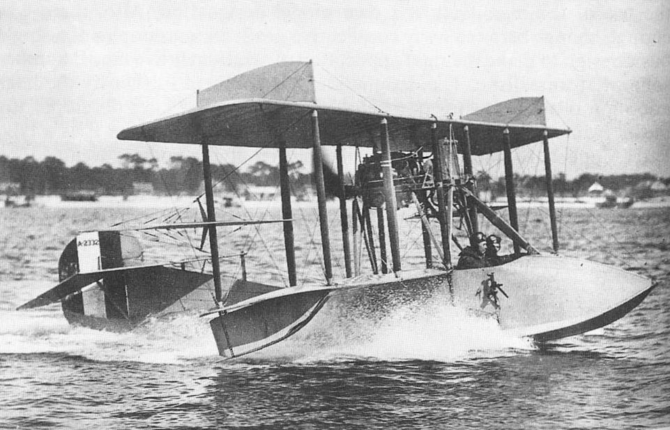
1914 Model. The standardized Model F of 1914 differed noticeably from the 1913 versions, particularly in having equal-span wings with rounded tips projecting beyond the end struts and a hull with full-depth primary structure and a rounded wood veneer foredeck. On some civil models, the foredeck hinged forward to form a gangplank for crew movement to or from a beach. An additional feature was a diagonal strut from the engine mount to the lower forward hull structure, intended to protect the crew from a falling engine in a crash. This became known as the Goodier strut since it was installed as the result of Army Lt Lewis Goodier's crash in the Army's first F-boat, S.C.15.
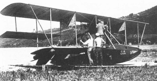
US Navy C-1/C-5 (AB-l/5). The Navy bought five early flying-boats from Curtiss and designated them Navy Type C. Numbering was in sequence of delivery, but the 'boats were not identical, ranging from one of the experimentals modified to near-production standard (C-1/AS-1) to the stock F-boat. On 30 August, 1913, the C-2 flew at Hammondsport under the complete control of a Sperry gyroscopic automatic pilot. The C-boats were redesignated as ABs with the same sequential numbers on 25 March, 1914.
The AB-3 became the first US military aircraft to see action. It was transported with AH-3 to Vera Cruz, Mexico, aboard the cruiser Birmingham, arriving on 21 April, 1914. On 25 April, Lt P. N. L. Bellinger piloted AB-3 on a reconnaissance mission over the city of Vera Cruz and surveyed the harbour for mines. AB-3 later had its wings shortened and was used as a non-flying 'Penguin' taxying-trainer.
US Army 15, 34, 49. The three Curtiss flying-boats delivered to the Army between November 1912 and December 1915, were identified in service only by their Signal Corps numbers. In detail they ranged from composite-hull 'E-boat' (No.15) to the standardized 1914 model mahogany-bull F-boat (Nos 34, 49).
Model F (Revised)
The basic single-engine pusher-type F-boat of 1913-14 was ordered in small numbers by the Navy to the end of 1916. After US entry into the war in 1917, orders were increased when the design was chosen as the Navy's standard primary training flying-boat; 144 were procured after April 1917 and production continued into 1918 until replaced by the MF, yet the F was overlooked in the 1935 redesignation.
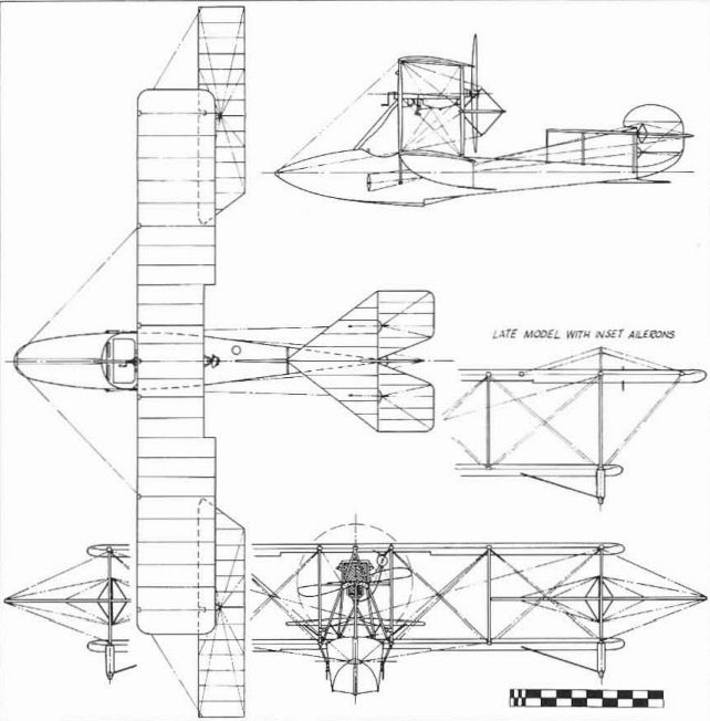
The 1917-18 Model Fs were greatly improved over the 1914 model, the principal change being redesign of the control system to delete the shoulder-yoke aileron control, both Services having agreed to standardize on the Deperdussin system in August 1916. Various wing modifications were tried on a few examples, among them extension of the upper wing span to 45 ft 1 3/8 in (13,75 m) and transfer of the interplane ailerons to the upper wing. Several F-boats were fitted out as aerial ambulances, with provision for a litter to be carried on top of the hull behind the cockpit. Powerplant was the 100 hp Curtiss OXX-3.
Costing $7,500, less GFE, new, surplus F-boats came on the postwar market priced at $1,750 and saw relatively wide use by private owners. US Navy serial numbers: A145, A146, A386, A387, A390/393 (4), A408, A752/756 (5), A2279/2281 (3), A2295/2344 (50), A3328/3332 (5), A4079/4108 (30), A4349/4402 (54), A5258
Revised 1917 Model F
Trainer flying-boat. Two pilots.
100 hp Curtiss OXX-3.
Span 45 ft 1 3/8 in (13,75 m); length 27 ft 9 3/4 in (8,47 m); height 11 ft 2 13/16 in (3,42 m); wing area 387 sq ft (35,95 sq m).
Empty weight 1.860 lb (843,68 kg); gross weight 2,460 lb (1.115,83 kg).
Maximum speed 69 mph (111 km/h); climb to 2,300 ft (701 m) 10 min; service ceiling 4,500 ft (1.372 m); endurance 5,5 hr at cruising speed.
Model K (Model 4)
The Model K of 1915 was a logical development of the popular Model F flying-boat. It was larger, more refined in detail, and was powered with a 150 hp Curtiss V-X engine in the now traditional between-wings pusher location. Other than size, the distinctive differences between the F and the K were the heavy stagger of the K wings, the use of ailerons inset into the upper wing, and a V-bottom for the hull.
The K-boats did not sell well in the US but enjoyed a brisk export trade. Some, sold to Russia and delivered after many delays, were unseaworthy when set up because they had lain in their shipping crates so long that their wooden hulls had dried out and opened up numerous cracks.
Model K
Three-seat military flying-boat. 150 hp Curtiss V-X.
Span 55 ft 9 7/8 in (17,01 m); length 31 ft 5 1/4 in (9,58 m); wing area 592 sq ft (54,99 sq m).
Empty weight 2,700 lb (1,225 kg); gross weight 3,900 lb (1,769 kg) .
Maximum speed 70 mph (112,65 km/h); rate of climb 150 ft/min (0,76 m/sec); range 364 miles (586 km).
G.Swanborough, P.Bowers United States Military Aircraft Since 1909 (Putnam)
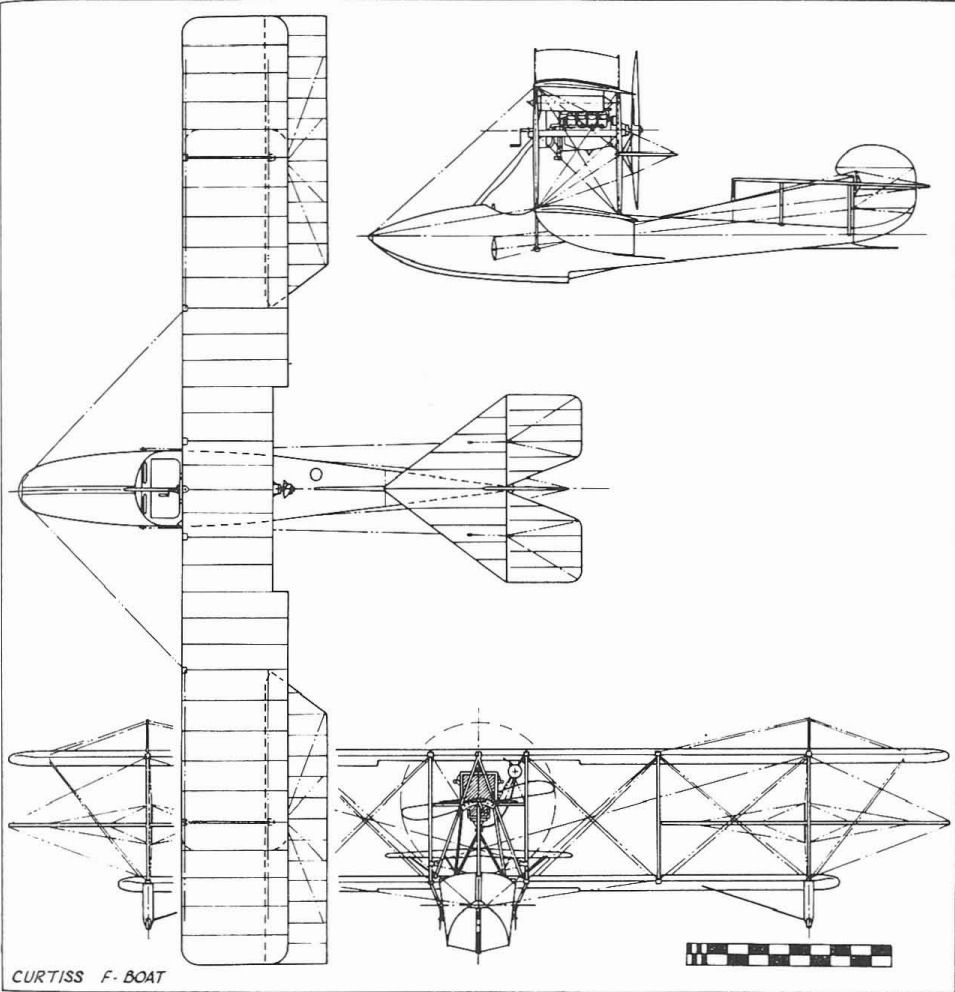
CURTISS F-BOAT
The Curtiss Model F was a single-engined pusher flying boat developed in 1912 and supplied to pre-war private owners as well as to the Army which bought three (15, 34, 49), and the Navy. In keeping with most train¬ers of the 1910/14 era, the F was a side-by-side two seater. The hull was built up of cross-lapped wood veneer strips formed over wooden longerons and bulkheads. Wing details varied between individual machines, some having equal span wings and interplane ailerons while others had an over-hanging upper wing with integral ailerons. Span, 43 ft. 10 in.; length, 27 ft. 9J in.; area 387 sq. ft.; gross weight, 1,860 lbs.; speed, 69 m.p.h.
G.Swanborough, P.Bowers United States Navy Aircraft Since 1911 (Putnam)
Curtiss F-Boat
The Curtiss model F was an early development of the original Curtiss pusher flying-boat of 1912, the world's first successful f1ying-boat. Designation of the US Navy models is confusing because procurement of the basic design bridged the changeover from the original Navy system of designating aircraft by code letters for the manufacturer and type to the use of the manufacturer's own model designation. Also, there was enough change between early consecutive production examples of a single basic design to make the rigid application of an all-inclusive model number somewhat unrealistic. The designation was confused further by the later adoption of the British F (for Felixstowe) symbol for later developments of the twin-engine Curtiss H series, and the practice of using F as a type letter applied to small single-engine pusher flying-boats developed by other manufacturers.
The major production version of the Curtiss F used a hull built up of laminated wood veneer strips which were shaped and glued up in a jig before being applied to the wooden hull frame. The student and his instructor sat side by side in a single cockpit ahead of the wings. Wing shape varied during the production life of the F, which continued into 1918. Some had equal-span wings with ailerons mounted between the panels, and some had the ailerons built into the upper wing. Overhang was added to the upper wing to increase lifting area on some models. Early models had fabric stretched between front and rear struts just outboard of the engine to serve as anti-skid vanes; later models had fabric applied between the kingposts that braced the upper wing overhang to serve the same purpose.
The first five Navy F-boats, all differing in detail, were procured as Navy models C-1 through C-5. In March 1914 these machines were redesignated AB-1 through AB-5, the letter A designating Curtiss as the first manufacturer of aircraft for the Navy and the letter B identifying the type of the machine as a flying-boat. As ABs, these machines contributed much to early Navy aeronautical development. In December 1912 one boat, believed to have been the C-1 at the time, was launched from a catapult mounted on a dock at the Washington Navy Yard. AB-2 was later catapulted from a barge moored at the Pensacola Naval Air Station in Florida and on November 5,1915, Lt Cdr H. C. Mustin, Naval Aviator No. 11, made the first Navy catapult launch from a ship when he successfully left the battleship USS North Carolina in the AB-2. The ship was at anchor at the time and the catapult was directed straight astern.
Several of the ABs accompanied the Navy to Vera Cruz, Mexico, in April 1914. Carried aboard the USS Mississippi, AB-3 was flown from the water by Lt (Jg) P.N. L. Bellinger in the first operation of US military aircraft against another country. The first flight, made on April 25, was for observation purposes and to look for mines in the harbour. The second, made on April 28, was a photographic mission. Upon its return to the United States, AB-3 had its wings shortened and finished its career as a non-flying 'penguin' trainer.
At least 144 additional trainer flying-boats were ordered from Curtiss under the F designation. More show up in Navy serial number listings, but these are mixed among the later Curtiss MF models that began replace the Fs in 1918 and Fs built to Curtiss' or their own design by other manufacturers. The Burgess Company of Marblehead, Mass., was to have built Curtiss Fs under licence but was switched to the production of Curtiss N-9s, and produced only one Curtiss F (A2281).
TECHNICAL DATA (F-Boat)
Manufacturer: Curtiss Aeroplane and Motor Co, Inc, Hammondsport, and Buffalo, NY.
Type: Flying-boat trainer.
Accomodation: Pilot and instructor side by side.
Pover plant: One 100 hp Curtiss OXX.
Dimensions: Span, 45 ft 1 3/8 in.; length, 27 ft 9 3/4 in; height, 11 ft 2 3/4 in; wing area, 387 sq ft.
Weights: Empty, 1,860 lb; gross, 2,460 lb.
Performance: Max speed, 69 mph at sea level; initial climb, 10 min to 2,300 ft; service ceiling 4,500 ft; endurance, 5.5 hrs.
Serial numbers (known):A145; A146; A386; A387; A390-A393; A408; A752-A756; A2279-A2281; A2295-A2344; A3328-A3332; A4079-A4108; A4349-A4402; A5258.
L.Opdyke French Aeroplanes Before the Great War (Schiffer)
Deleted by request of (c)Schiffer Publishing
The Paulhan-Curtiss F-Boat included many Curtiss-built parts. Paulhan himself flew it on its first test in France on 29 December 1912 at Bezons, on the Seine. It differed from its American cousin in having a flexible, rather than a hinged, elevator surface; a single diagonal strut supported only the leading edge of the wing overhang, rather than the pair used in the American version. At least 4 of the French-made boats were sold to Italy.
(Span: 10 m; length: 8.5 m; gross weight: 500 kg; Curtiss 0X5)
Jane's All The World Aircraft 1913
CURTISS. Curtiss Aeroplane Co., Hammondsport, N.Y. Glenn H. Curtiss in 1907 and 1908 was a member of the Aerial Experiment Association, formed by Dr. and Mrs. Alexander Graham Bell. This Association built four machines, each along the lines of one of the four engineers belong to the Association, F.W. Baldwin, Lieut. T.E. Selfridge, G.H. Curtiss and J.A.D. McCurdy. The last built was the June Bug, designed by Curtiss and was the most successful. In the spring of 1908, the Association was disbanded and The Aeronautical Society gave Curtiss an order for an aeroplane with carte blanche as to design. He produced a 4 cyl. machine, Curtiss engine, and flew it. A duplicate was hurriedly built, 8 cyl. engine installed, and taken to Europe for the first Gordon Bennett, which he won. Returning, the same type was continued with minor improvements. Later the front elevator was brought closer in, finally discarded, and the fan tail adopted and this remains the standard land machine to-day. In April, a military tractor was built and flown.
On January 26th, 1911, first successful flights were made with a hydroaeroplane, at the Winter camp at San Diego, Calif. This had two floats tandem. One was finally adopted and great success was achieved, and remains standard at the present time. With this machine various experiments were made. It was altered in a tractor for one occasion, it was lifted on board warships; made into triplane, etc.
In 1912 he brought out his present type of flying boat. This is being rapidly developed and minor changes in details are made in practically every machine put out.
In May, 1913, he produced a special 4-passenger flying boat for a customer on special order.
Note.--In addition to those tabulated, special small racing machines have been built, as well as similar machines with extra sections simply added either side for Army use.
Model and date. Type D. Type E. Type F.
1913. 1913. 1913.
Length......feet(m.) 26-2/3 (8.1) 27-1/3 (8.33) 27-1/3 (8.33)
Span........feet(m.) 26? (8) 31? (9.50) 38-1/3 (11.70)
Overall.....feet(m.) 33-1/12 (10) 36? (11) 41-2/3 (12.70)
Area...sq. feet(m?.) 214 (19?) 288 (26?) 421? (39)
Weight,
total...lbs.(kgs) ... 1700 (771) ...
useful...lbs.(kgs) ... 500 (227) ...
Motor...........h.p. Curtiss 80 Curtiss Curtiss
Spee.....m.p.h.(km.) ... 59 (95) ...
Remarks.-- Land service, Fitted either Used to date only
but is also with wheels, as military tractor
made with pontons, or boat. or heavy flying boat.
floats. Vilas boat. McCormick boat.
Panels.
Boat 24 ft. long. Boat 25 ft. long 4 ft.
Beam 54? ft. wide. Freeboard 46
Height 41" long. ins. Cockpit 84 ins.
Cockpit 3 ft.long long by 46 ins. wide.
by 4 ft. 2 ins. Length of tail, incl.
wide. elevator 12 feet.
For full details of the tractor (F) see Aeronautics, U.S.A., February, 1913.
Jane's All The World Aircraft 1919
Curtiss Model M.F. Flying Boat.
Specification.
General Dimensions.
Wing span, upper plane 49 ft. 9 3/8 in.
Wing span, lower plane 38 ft. 7 5/32 in.
Depth of wing chord 60 in.
Gap between wings at engine section 6 ft. 4 5/32 in.
Stagger None.
Length of machine overall 28 ft. 10 3/16 in.
Height of machine overall 11 ft. 9 3/8 in.
Angle of incidence 6 degrees.
Dihedral angle, lower planes only 2 degrees.
Sweepback None.
Wing curve U.S.A. No.1.
Horizontal stabilizer
angle of incidence 0 degrees.
Areas.
Wings, upper 187.54 sq.ft.
Wings, lower 169.10 sq. ft.
Ailerons (each 22.43 sq. ft.) 44.86 sq.ft.
Horizontal stabilizer 33.36 sq. ft.
Vertical stabiliser 15.74 sq. ft.
Elevators (each 15.165 sq. ft.) 30.33 sq. ft.
Rudder 20.42 sq. ft.
Total supporting surface 401.50 sq. ft.
Loading (weight carried per sq. ft.
of supporting surface) 6.05 lbs.
Loading (per r.h.p.) 24.32 lbs.
Weights.
Net weight, machine empty 1.796 lbs.
Gross weight, machine and load 2,432 lbs.
Useful load 626 lbs.
Fuel 240 lbs.
Oil 22.5 lbs.
Water 36 lbs.
Pilot 165 lbs.
Passenger 165 lbs.
Miscellaneous accessoires 7.5 lbs.
Total 636.0 lbs.
Performance.
Speed, max. (horizontal flight) 69 m ph.
Speed, mm. (horizontal flight) 45 m.p.h.
Climbing speed 5.000 ft. in 27 mins.
Motor.
Model O.X.X. 8-cylinder, Vee, four-stroke cycle
Water cooled.
Horse power (rated) at 1400 r.p.m. 100
Wright per rated h.p. 4.01 lbs.
Bore and stroke 4 1/2 in. x 5 in.
Fuel consumption per hour 10 galls.
Fuel tank capacity 40 galls.
Oil capacity provided, crankcase 5 galls.
Fuel consumption per b.h.p. .60 lbs. per hour.
Oil consumption per b.h.p. .030 lbs. per hour.
Propeller.
Material. - Wood.
Pitch. - According to requirements of performance.
Diameter. - According to requirements of performance.
Direction of rotation, as viewed from pilot a seat. - Clockwise.
Details.
Dual control.
Standard Equipment. - Tachometer, oil gauge, gasoline gauge, complete set of tools.
Other equipment on special order.
Maximum range.
At economic speed, about 325 miles.
J.Davilla Italian Aviation in the First World War. Vol.2: Aircraft A-H (A Centennial Perspective on Great War Airplanes 74)
Curtiss Model F
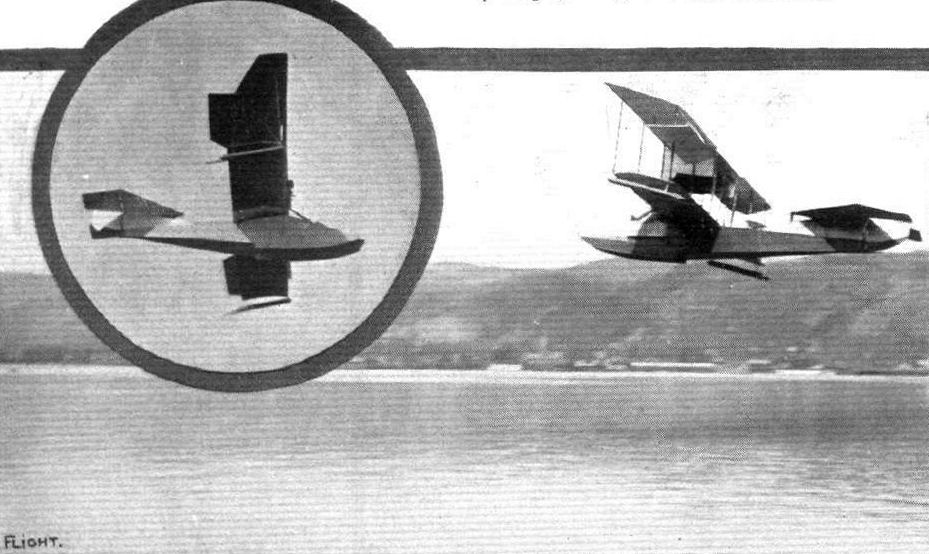
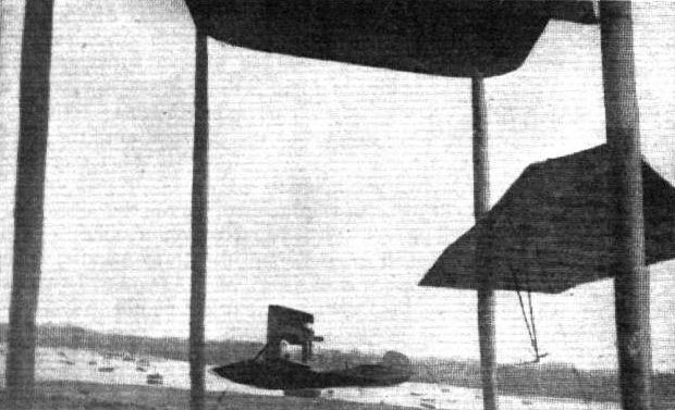
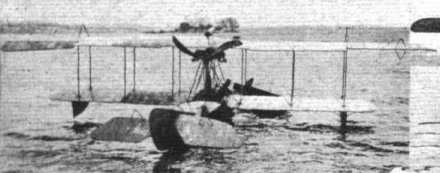
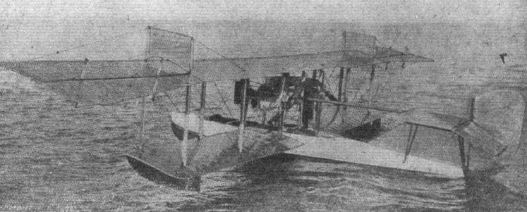
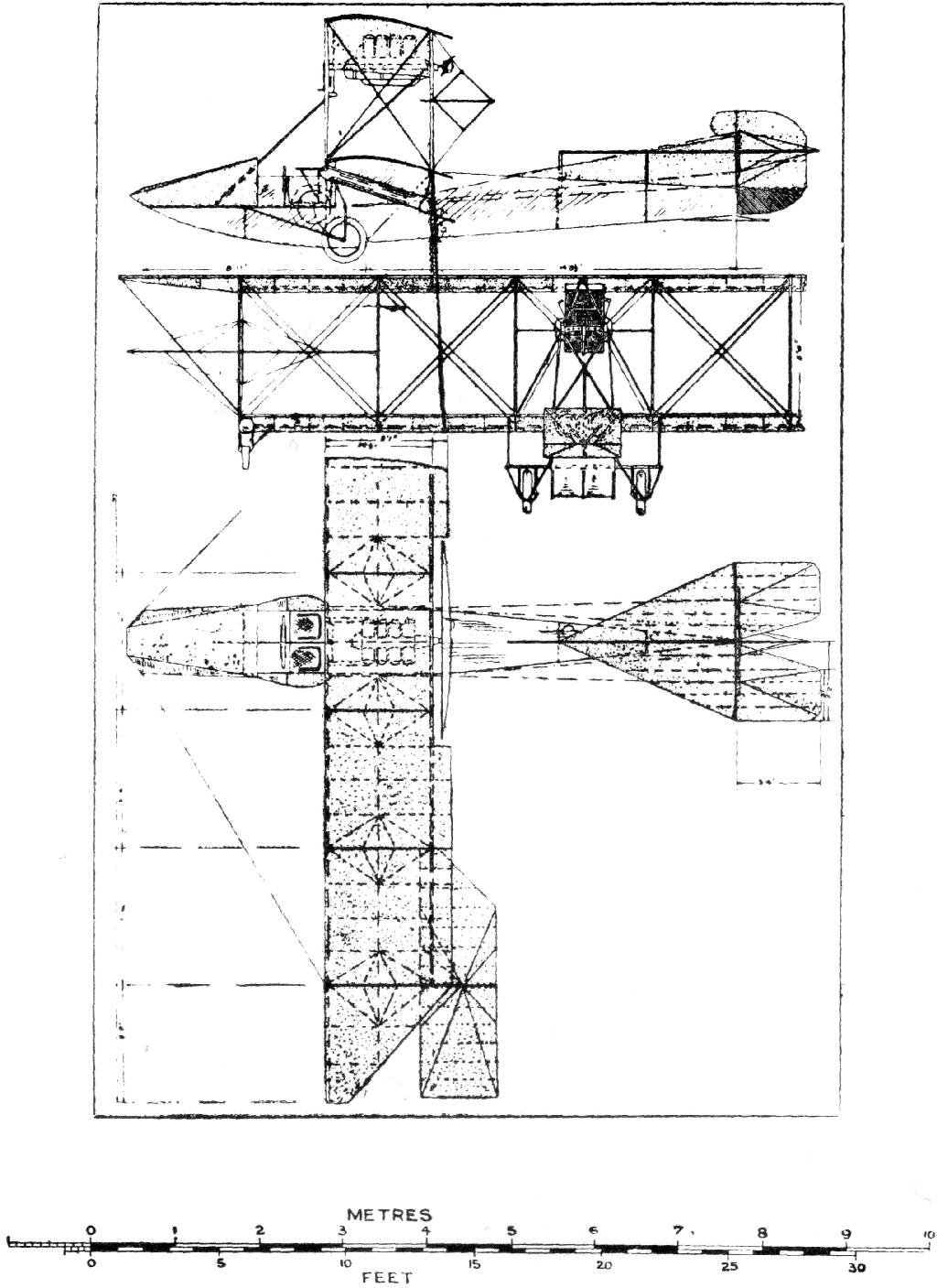
In 1913, the Italian Navy placed an order for three Curtiss Model F flying boats with specifications that differed from any previous hull design. The hull sides were to be straight instead of flared, as was then the custom. The flared hull was designed to accommodate the side-by-side seating and shoulder yoke control system still in use by Curtiss. The hulls of these Italian Navy boats were narrower, with the occupants seated in tandem. The slab-sided construction made it possible to plank the whole side with one sheet of three-ply mahogany rather than the strip planking then in common use.
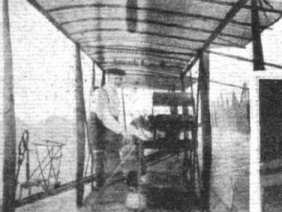
An unusual and distinguishing feature was the hood for the occupants. The fabric hood was like a carriage hood, running longitudinally with transparent panels fitted in the cloth between ribs and across the front. The opening was along the top center line, like an oyster shell, and the hood could be folded down inside of the elliptical-shaped cockpit. The Curtiss controls were changed to a control wheel, something with which the Italian pilots would be more comfortable.
The inboard wing panels were fitted with a transparent strip that made it possible for the rear occupant to look directly downward. The engine was braced against longitudinal movement by two bracing members that ran down at about a 45-degree angle from the engine bed to the forward deck. Bracing wires extended from the upper bow to the middle interplane struts. The empty weight was approximately 1,440 pounds.
Aero and Hydro, February 7, 1914, reported; CURTISS “CABIN” BOAT FLIES SUCCESSFULLY Hammondsport, N.Y, January 31. Raymond V. Morris today made a series of flights here in a new flying boat built by the Curtiss Company for the Italian Navy. The machine differs from other Curtiss flying boats in that it has an entirely enclosed cockpit or cabin, seats arranged in tandem, and an oddly shaped hull intended for work on large bodies of water. The crew are well sheltered from the elements that waves washing entirely over the craft would not touch them nor could they swamp the boat. Morris, accompanied by an official observer, put the boat through the usual series of altitude, speed, and weight carrying tests.
The first Model F was evaluated in January 1914; after testing had been completed in Venice the first examples were ordered by the Regia Marina. Initially ten were ordered, but this number was subsequently increased to 24. They were produced by the Enea Bossi company in Milan in early 1915. Bossi had by that time obtained the Curtiss production license for the Italy and had them built by the Zari brothers’ factory.
At the beginning of 1916 there were 33 Model Fs listed on strength in the official history. They had, however, been SOC by mid-year. While the speed and climb rate were slow and the climb time high; their in-flight stability was satisfactory, and perhaps more importantly, the Model F handled well in rough seas.
The Achille’s heel of the design was the Curtiss engine which suffered frequent breakdowns. This resulted in poor serviceability and aircraft being forced down at sea. Later in some aircraft the American engine was replaced with a 110-hp Colombo D.110 national engine, achieving a speed increase of 15 km/h; it is unclear as to when this was done.
Despite the decision to fit them with more powerful Colombo engines, the type was soon replaced by Lohners or at least their Macchi equivalent.
Curtiss Model F with 90 hp Curtiss engine
Wingspan, 13 m; length, 8.20 m; height, 3 m; wing area, 42 sq m;
Empty weight 530 kg; loaded weight 800 kg; payload 270 kg
Maximum speed 85 km/h; climb to 500 m. in 12 minutes, range 430 km, ceiling 1,000 m
Журнал Flight
Flight, January 4, 1913.
EDDIES.
Paulhan has been flying again. Last Sunday afternoon, on the Seine, at Bezons, he was carrying out tests on a new Curtiss flying boat of which he had just received delivery from Hammondsport, U.S.A. The machine was just unpacked, erected, run down the slipway into the river, the engine started and away he flew without any delay for adjustment of any kind. Fitted with an 80-h.p. water-cooled Curtiss motor, the machine showed its ability to maintain a speed of over 60 miles an hour, with a pilot and passenger on board. The machine by itself, with petrol and oil aboard, weighs less than 1,150 lbs.
Flight, February 28, 1914.
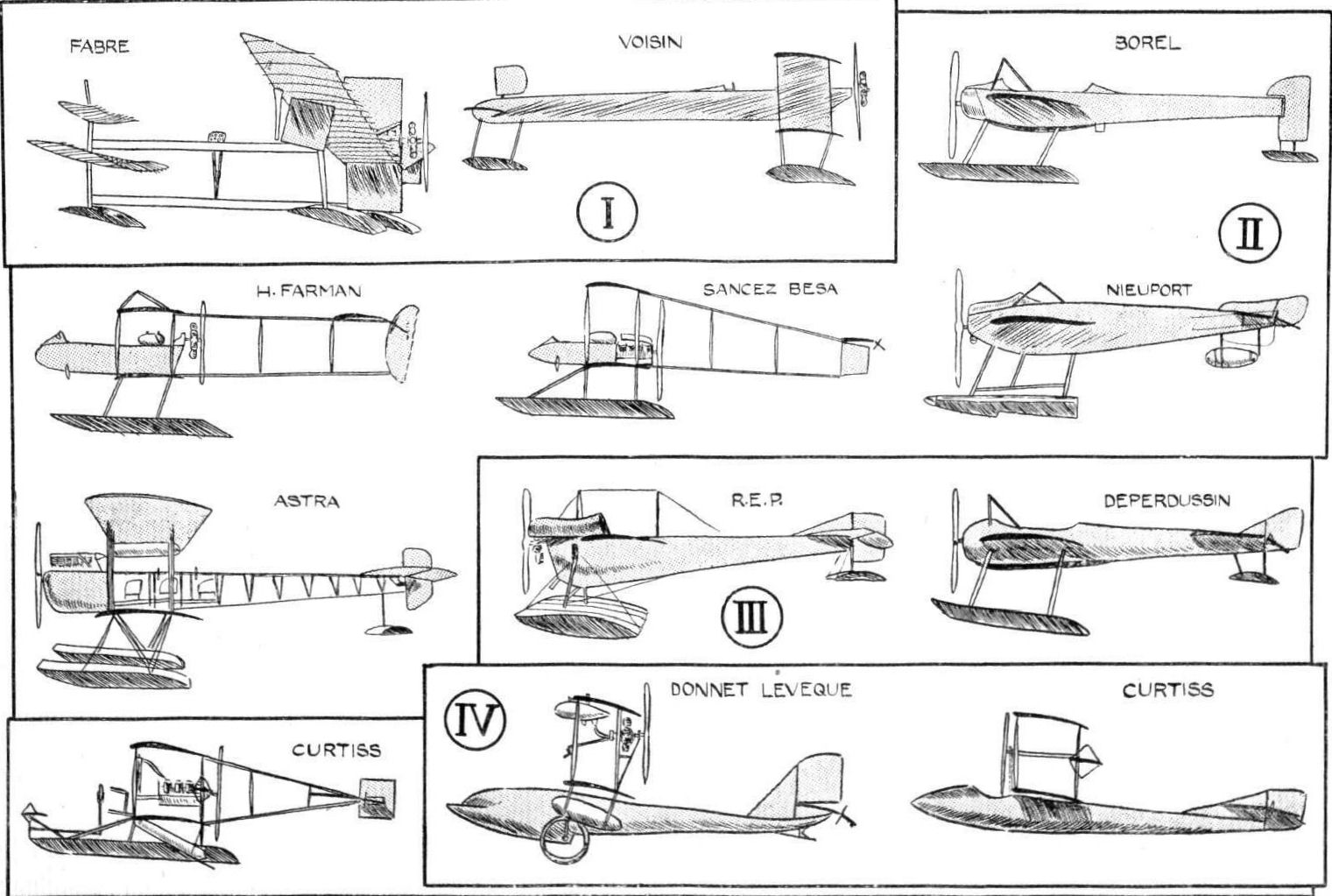
SOME AMERICAN FLYING BOATS.
IN view of the announcement that an attempt is to be made during the coming summer to cross the Atlantic in a Curtiss flying boat, and bearing in mind the popularity this type of aircraft has attained in the United States, the following brief descriptions of some of the most successful American flying boats will enable our readers to form some idea of the stage to which this form of hydro-aeroplane has been developed. It is a fairly safe guess that for any attempts made under American auspices machines of the flying boat type will be employed, for in no other country have so many different constructors turned their attention to this particular type.
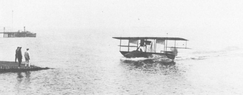
Since the Curtiss flying boat is the first to be entered, and as moreover its designer, Mr. Glenn Curtiss, is the pioneer of hydro-aeroplaning in America, it is only natural to begin this article with a description of one of the flying boats turned out by that most versatile constructor, more especially in view of the fact that the Curtiss machines are now being constructed in this country by Messrs. White and Thompson, Ltd., of Middleton, Bognor, Sussex. It is not easy to choose a model for description, for the dope has hardly had time to dry on the planes of one machine before a new and improved one is put through its trials. However, the flying boat built by the Curtiss Company for Mr. Harold F. McCormick, of Lake Forest, Ill., is fairly typical, as it embodies standard Curtiss features as well as several innovations which will be adopted in future machines. The boat, which is 23 ft. 7 ins. long, is built up of longitudinal members of ash I in. square, and placed 6 ins. apart, carrying the ribs, which are spaced 3 ins. apart. Over this framework is secured the planking, which for the sides of the boat consists of a thin spruce skin, whilst the bottom is covered with a planking of 5/16 in. thick mahogany and 3/4 in. spruce laid diagonally and having a sheet of very thick fabric, set in marine glue, between them. The whole outside of the hull is then covered with watertight canvas. Eight bulkheads divide the boat into watertight compartments, each of which is provided with an inspection door, which permits examination of the interior of the boat. Two of these compartments are claimed to possess sufficient buoyancy to keep the machine afloat should the remaining seven, for some reason or other, spring a leak. The bottom of the boat has a step of rather unusual shape. Instead of the usual box step, the step in this machine is of triangular form when viewed in plan, and has its apex pointed forward. Air is admitted to the step by two 1 1/2 in. copper tubes extending upwards through the hull. From the step the boat slopes upwards in order to facilitate getting off without the rear portion dragging. The body tapers to a vertical knife's edge at the rear, where are mounted the tail planes, consisting of fixed tail planes mounted a short distance above the hull and a divided elevator, hinged to the trailing edge of the fixed plane, a vertical fin and the rudder.
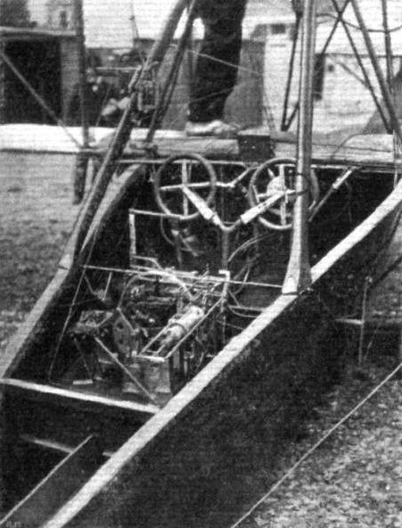
Just in front of the lower plane, and arranged side by side, are the pilot's and passenger's seats. In front of them are the dual controls, which consist of two rotatable hand wheels mounted on a single column, so that the machine can be controlled by either pilot or passenger at will. A to and fro movement of the wheel operates the elevator, whilst rotation of the hand wheel actuates the rudder.
The ailerons are operated by means of the shoulder yoke fitted as standard on all Curtiss machines, but any other control may be fitted. The deck of the boat in front of the occupants is swept upwards to form a wind shield. The gap between the main planes, of which the lower one is mounted on the upper longerons of the boat, is 5 ft. 6 ins., and the chord is 5 ft. 7 ins. Mounted on very strong bearings between the planes is the engine - a 100 h.p. 8 cyl. Curtiss - driving directly a propeller situated behind the main planes. A very stout oblique strut runs from the front part of the engine bearers to the upswept nose of the boat, and serves to transmit the strains due to momentum from the engine to the boat on alighting. On either side of the engine, and slung from the struts by means of steel straps, are the two tanks which contain the fuel, of which a supply sufficient for a six hours' flight can be carried. Outside the tanks, and immediately under the top plane are situated two blinkers, the object of which is to counteract, to a certain extent, the side area of the boat. The ailerons, which are of the usual Curtiss type, are pivoted approximately at their centre of pressure, so that little or no power is required to operate them, and they are inierconnected in such a manner that the drag on that of the lower wing is the same as that on the higher wing, so that there is no necessity to use the rudder in conjunction with the ailerons in order to maintain the direction of the boat. The general dimensions of the machine are :-
Span 42 ft, 2 ins.; Area 400 sq. ft.
Length 23 ft. 7 ins.; Weight 1,520 lbs.
Chord 5 ft. 7 ins.; Speed 53 m.p.h.
Gap 5 ft. 6 ins.
Flight, July 3, 1914.
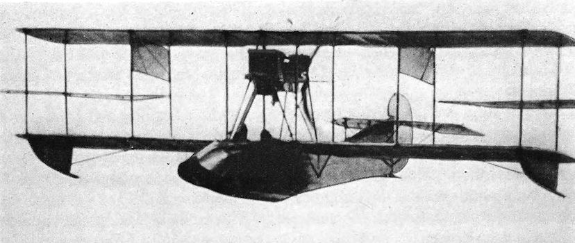
TESTING THE SPERRY-CURTISS STABILIZER.
SOME very interesting demonstrations are reported to have been made with the Sperry stabilizer fitted on a Curtiss flying boat, in connection with the "Concours de la securite en aeroplane" on Friday week. The scene of the demonstrations was the Seine at Bezons, and the tests were carried out under the official observation of the judges of the competition. Piloted by Mr. Sperry, Jun., the son of the inventor of the gyroscopic stabilizer, the Curtiss flying boat left the water easily and rose to a height of about 400 ft. The mechanic was then seen to leave his seat and walk out along the lower plane, whilst the pilot held his hands above his head in order to show that the machine was controlled by the stabilizer only. This performance was repeated several times, and on another flight Mr. Sperry was accompanied by one of the judges - Commandant Barres - in order to make absolutely certain that the pilot did not use the controls.
The Sperry gyroscopic stabilizer consists of a quadruple gyroscope actuating the ailerons and elevator, and driven by the engine at the rate of 12,000 r.p.m. The longitudinal attitude of the machine is regulated by means of a small wind vane (which is seen in our photograph at the top left, attached to one of the engine struts) actuating one of the gyroscopes. If the speed of the machine drops below a certain limit, the vane depresses the elevator through the intermediary of the gyroscope. If, on the other hand, the speed is increased owing to a dive, the elevator is pulled up so as to "flatten out" the path of the machine. A clutch is provided by means of which the gyroscopes can be brought into or put out of action at the will of the pilot.
Flight, April 30, 1915.
EDDIES.
IT seems that the Sperry gyroscopic stabilizer is going strong on the "other side." Partly by way of giving another demonstration of its capabilities and partly because he wanted to qualify for his "expert" certificate, the inventor, Mr. Lawrence B. Sperry, with Mr. Alan R. Hawley, President of the Aero Club of America, as passenger, took his Curtiss flying boat, which is fitted with the stabilizer, for a spin round Manhattan and the Statue of Liberty. They left the New York Navy Yard at Brooklyn, and soon rose from the water after passing Williamsburg Bridge. Following the course of the East River, the Harlem Ship Canal, and then the Hudson River, they flew over the Hudson to Ossining, where they circled several times, and then turned back. On the way down from the upper end of Manhattan Island, the craft had been flying about level with the top of the houses (no mean height in New York), but, on nearing the City, Mr. Sperry noticed that the air currents were growing more choppy, and so rose to a height of 500 ft. Down the river once more and into the bay sped the flying boat, quickly circling the Statue of Liberty. Then the craft steered over Brooklyn Bridge and, dipping under Manhattan Bridge, with little room to spare, alighted at the Navy Yard, from which it had started. The distance covered in the flight was 80 miles there or thereabouts.
Flight, April 6, 1916.
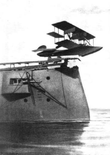
LAUNCHING SEAPLANES FROM BATTLESHIPS.
THE U.S. NAVY METHOD.
SINCE the days when a Curtiss hydro-aeroplane first left the deck of a battleship the problem of starting from and lighting on a man-of-war has received great attention both in America and other countries. While under favourable conditions it has been possible for one of the old-type slow seaplanes to alight on the deck of a ship the difficulties of so doing are very great, and it has become general practice to let seaplanes alight on the sea, to be hoisted on board afterwards. As regards starting from the deck of a ship, one of the difficulties is that of providing a sufficiently long platform to allow the seaplane to gather sufficient velocity to sustain it when it has left the launching platform. For the following description of how this is accomplished in the U.S. Navy we are indebted to our contemporary Scientific American:-
"The seaplane as a naval scout should be able to operate from a moving ship as a base, and to do this with much the same indifference to the state of the weather as its fellow in the military service, starting aloft from the ground. Otherwise its nautical usefulness would in no way be comparable with that so splendidly discharged by aircraft in the army. The stumbling block has been very largely the seaplane's inability to get a start from rough waters. The sturdiest of them are able to land upon something-of a troubled sea but their pontoons do not permit them to gain sufficient speed under those circumstances to insure the take-off for a flight. Therefore, even though they might be put overboard safely in the lee of a ship it has not been possible, except under the most favourable conditions of the water, to get them away in flight.
"But this difficulty has been surmounted here, thanks to the initial work of Captain Washington I, Chambers, U.S.N., who gave us the idea of a catapult launching apparatus for naval aircraft. As a practical naval man, this officer realised that no fighting ship could afford to be encumbered with long launching platforms such as were tried first here and then experimented with abroad. He knew that space must be economised and the sweep of guns uninterrupted. Therefore he conceived a short-run catapulting railway that could be quickly erected and just as rapidly dismantled and stored away. His first apparatus was tested over three years ago at the Washington Navy Yard, and as an outcome of those promising experiments a new machine was designed and sent to the Aeronautic Station, Pensacola, Florida.
"There it was installed at the start upon a coal barge and thoroughly tried out. As a result of its success the apparatus was removed and placed permanently aboard the U.S.S. 'North Carolina.' It is from this ship that seaplanes have repeatedly been launched in the past few weeks in the open sea and with the armoured cruiser underway. Despite the fact that one of the older and heaviest of the service aeroplanes has been used in these trials, still the catapult has answered admirably and has taken care of the load imposed upon it again and again. This point is suggestive, because the weight factor may be taken to represent either a long-range scout or a lighter seaplane equipped with bomb-dropping apparatus.
"In principle, the launching device consists fundamentally of a car propelled along a narrow-gauge track. Upon this car rests the seaplane, and the aircraft is secured to the vehicle until the latter reaches the end of the runway. When the car stops the seaplane is automatically released, and the acquired inertia suffices to sustain the flying machine until its propellers are able to provide the necessary propulsive effort. As a rule, however, the aircraft's motors will be speeded up to this point by the time the end of the track is reached. The method of operating is as follows: The plane is lifted on to the car and secured to it, then the motors are set going but not at full speed. This is accelerated after the catapulting begins. The aviator takes his seat in his craft, and when everything is in readiness the car, with its load, is drawn along the track at an increasing rate. This gathering momentum is so nicely controlled that a velocity of about 50 miles an hour is attained by the time the aeroplane is cast loose from the car. The car is brought to a standstill a very few seconds later.
"Originally, the truck was sent overboard at the end of its run, but in service aboard a ship underway at sea this would be undesirable, because it would be necessary either to stop or slacken speed in order to haul the car aboard even if it were held by a line. Clearly it would be impracticable to abandon the truck and to hold in reserve any number of them. The motive power employed for moving and speeding up the catapult car is compressed air. By means of a throttle worked by a cam, the air impulse is progressively increased upon the operative piston or plunger which functions the wire rope purchase by which the truck is pulled during its comparatively short run of something less than 50 feet. The actual stroke of the piston is in the neighbourhood of one inch for each foot of advance on the part of the truck; the turns of the wire rope over pulleys serving to produce this multiplication of movement. The air required by the catapult is supplied from the torpedo air service of the cruiser and at a pressure of something like 300 pounds per square inch.
"The runway is made up of light steel angle iron and raised only three feet or so above the ship's deck, to which the structure is secured by attachments that can be quickly released when it is desired to dismount the apparatus. The aviator is not jarred during the acceleration of the car and the final catapulting of the seaplane. The only sensation on the part of the pilot is like that due to a sudden blast of air in the face. The trials so far have been conducted with the 'North Carolina' steaming along at cruising speed.
"A scout cruiser is capable of covering a visual front of but 20 miles under favorable conditions of the atmosphere. An air scout 4,000 feet aloft can observe ships 70 miles away! There is no need of elaborating upon the strategic advantage obtained by the use of scouting seaplanes. It is just this widened field of observation which the aeroplane catapult makes possible."