Jane's All The World Aircraft 1919
WRIGHT-MARTIN. TYPE V.
Span 39' 8"
Chord 5' 10"
Gap 5' 7"
Stagger 1'
Dihedral 1 1/4 degrees
Span of Tail 12'
Area 223.2 sq. ft. (upper plane)
206.8 sq. ft. (lower plane)
Area of Aileron 64.6 sq. ft. (total of four)
Tail 57.2 sq. ft.
Fin 17.37 sq. ft.
Total Area 430 sq. ft.
Loading per sq. ft. 5.86 lbs.
B.N.P. 16.86 lbs.
Weight without engine 1130 lbs.
Weight of power plant complete 595 lbs.
useful load 445 lbs.
6 hrs. fuel 460 lbs.
Gross Weight 2630 lbs.
Motor-Simplex Model A.
Hispano-Suiza 150 h.p. at 1450 r.p.m
Propeller, diam. 8' 4"
pitch 5' 7 1/2''
Control Deperdussin type
Журнал Flight
Flight, March 22, 1917.
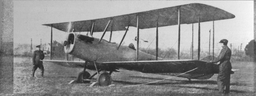
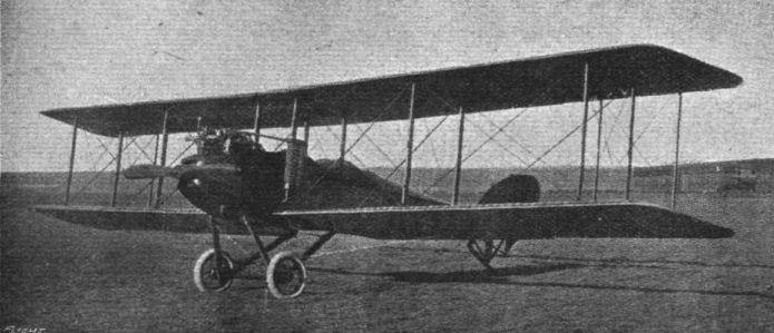
THE WRIGHT-MARTIN MODEL "V" RECONNAISSANCE BIPLANE.
THE Wright-Martin Model "V" is a two-seater tractor biplane of 150 horse-power, designed for long range military reconnaissance, with the observer's cockpit well forward of the entering edge of the lower wings.
The power plant consists of a Simplex Model A Hispano-Suiza eight-cylinder water-cooled engine (made under the Birkigt patent), driving direct a two-bladed tractor screw. The propeller is equipped with the French standard hub, keyed and locked to the tapered crankshaft extension.
As with the Model R, the motor unit is located in a demountable nose compartment, of tubular and pressed-steel construction, enclosed with hammered sheet aluminum bonnet fitted with large doors and louvred ventilators. The fuselage entry is formed by the oval German silver cellular radiator located immediately back of the propeller. The radiator is supported by novel means directly on the pyramided motor mounting, with a vibration-absorbing medium interposed. An oil radiator is located flush with the under cowl and connects with a separate oil tank of 4 gallons capacity in the rear of the engine compartment.
The wings are staggered and have a slight dihedral angle. Three sections comprise the upper plane, the two outer sections being attached to a central panel supported above the fuselage by two pairs of struts. The lower wings are in two sections attached direct to the fuselage. The hinged wing attachments are locked together with nickel steel quick-detachable pins. The curve is the Vought 4, developed to meet the requirements of maximum efficiency, wide speed range and structural safety. A noteworthy characteristic is the minimum translation of the centre of pressure throughout the useful range of incidence angles.
The chord, 5 ft. 9 1/2 ins., is the same for both planes, and a differential incidence setting is used. The curve permits of the employment of two very substantial spruce I-section main spars and a third stringer spar of the semi-continuous built-up type, the latter disposed between the main beams to increase the wing strength, and serve as an aligning member for the ribs themselves. These latter are of the built-up type, bench-made to metal patterns to insure uniformity and interchangeability. Rib materials are spruce for battens and poplar for webs, the assembly carefully glued up and brass nailed. Wide box ribs are used at all panel points and light false nose ribs of spruce are employed between the main ribs. All ribs are re-inforced to strengthen them in longitudinal shear. Leading edges are of spruce, hollowed, while the trailing edges are of white ash. Wing tip bows are of bent ash, hollowed and maple-dowelled to the spars and nose pieces. The lower wings are fitted with wide rubber stripped contre-plaque flooring at the roots, and have comfortable hand-hold grips adjacent to the rear spars at the tips.
All the wood-work of the wings is given one coat of wood filler and two coats of waterproof varnish; metal parts are given three coats durable enamel, baked on. This treatment obtains throughout the machine. The wing covers are made from uncalendered Irish linen, sewed and laid diagonally. The fabric is secured to the ribs by sewing and tacking and reinforced with suitable linen taping. The cloth is treated with five coats of Wright-Martin doping mixture, and finished with two coats of Glidden special flexible waterproof varnish.
In the cellule, the interplane struts are of solid spruce, streamlined and tapered and fitted with pressed steel socket ends. The fittings are stampings from chrome vanadium steel, with baked enamel finish. Turnbuckles are of the clevis-and-pin type, with nickel steel shanks and bronze barrels. All wires, struts and similar components are quickly detachable by removing nickel steel lock pins, and render assembly or replacement easy and very quick. Wires and turnbuckles are enamelled for preservation against weather. Roebling stranded cable is used, and all eyes have saddles, and are copper served and soldered. The lower wing trailing edges next the fuselage and the centre section are cut away to facilitate the pilot's view. Four large ailerons are hinged to the rear spars, having a semi-closed gap. Each aileron frame is of spruce and tubular steel, carefully reinforced, the covering and its treatment being the same as with the wings. Three hinges per aileron are employed and a very simple' and direct control is used, top and bottom ailerons being connected by spruce struts.
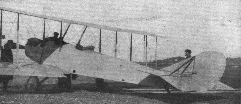
The fuselage is of rectangular section, fiat-sided, and fully enclosed, accommodating pilot and passenger in well-crowned and padded tandem cockpits - the pilot being placed in an advantageous position in the rear cockpit. A special feature is the detachable nose. This houses the motor and radiator, the fuel and oil tanks, equipment and supplies, and the live load being in well-arranged, compact, individual compartments in the main body. The fuel tanks are removed from proximity to the motor compartment to minimise fire risk, the service tank being located in the cowl aft of the front cockpit. The main tanks are placed longitudinally, and to the rear of the front seat on padded floor cradles. Fuel is supplied by pressure. An, air-pump, integral with the motor, serves the system, except for starting. The cockpit rims are padded and leather-covered, while the cockpits are upholstered in leather.
The fuselage tapers aft of the wings to a vertical tubular knife edge at the rear, which serves as an anchorage for the fin and rudder assembly. It is constructed, with the exception of the steel motor mounting, of ash and spruce longerons, struts and cross members, amply cross braced with Roebling's vanadium steel wire and Wright-Martin short-type turnbuckles. The fittings are substantial throughout, and, in the main, are steel stampings, embossed and die-formed from special steel. A substantial system of "follow-through" has been detailed into the fuselage design forward.
On the dashboard of the rear cockpit are neatly grouped the various flight and mechanical instruments. Transparent wind shields add to the comfort of pilot and passenger. Forward the fuselage is covered with sheet aluminium, whilst rearward linen fabric is employed, with provision for quick inspection of the truss members by means of a detachable deck. A large door renders the enclosed tail-skid mechanism get-at-able.
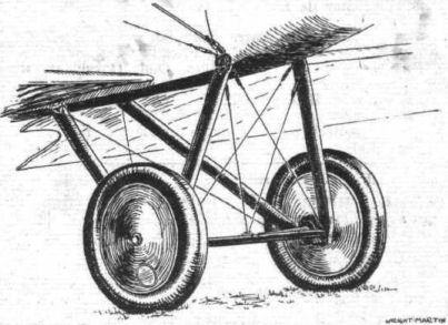
The chassis is of the two-wheeled type, and is designed to greatly minimise resistance. This cornponent is readily demountable as a unit, or individual parts may be disassembled with a minimum of inconvenience and disturbance of adjacent members. Practically all the parts are removable through the agency of quick-detachable nickel steel lock pins of large diameter. The chassis is composed of two sets of ash V struts of streamline section, combined with a streamlined system of twin parallel steel cross tubes attached to the steel boxes at the apices of the Vs, and an improved wheel and axle assembly. The whole unit is cross-braced with heavy cable and corresponding turnbuckles and fittings. The chassis struts are attached to the fuselage, with suitable steel clip-and-pin fittings. The cross tubes, or horizontal compression members, are of large diameter, and are fitted with forged q.d. clevis ends, pinned and brazed in. This member supports, and with its sheet aluminium stream line houses, the axle, which is hinged at the centre. The cross tube and axle hinge load is carried by two diagonal steel cables running up to the fuselage forward attachment plates. The axles are nickel steel tubing, specially heat-treated, and the outside diameter is large with a substantial wall thickness suitably reinforced at points of greatest load.
Either axle member can be withdrawn through its shock absorber spool, without affecting the adjustment of the shock absorbing mechanism. The axle hinge pins are quickly get-at-able by removing a small plate on the housing. The axles and rubber shock absorber retainers operate in a detachable enclosed guide of substantial construction and move vertically whilst the machine is taxi-ing. This design eliminates all Binding and the necessity of troublesome radius rod members. The shock absorbers are cotton encased rubber cord of large diameter, approximately 10 yards being used for each axle, and the strand is laced over and retained by belled steel spools of demountable construction. The wheels made in the Wright-Martin factory are of very sturdy construction, yet reasonably light. They are shod with 26-in. by 4-in. Goodyear double tube tyres, and have specially-designed hubs, with pressed steel flanges shrunk on, the spoke rows being more than 6 ins. apart. The spokes are heavy gauge, of best-quality steel, 36 being used to each wheel, tangent laced.
Bronze bushings are fitted and the hubs are self-lubricating, with grease capacity for a full season's use. Hexagonal bronze hub caps screwed on and pinned are used to hold the wheels in position. The air valve is accessible through a small circular aluminium door in the casing, which latter is of the same material as the wing covers, similarly doped and finished. The wheel tread is 5 ft. 3,5 ins., or slightly more than one-seventh the span of the lower wing. The weight of the complete chassis, including disc wheels and shock absorbers, is only 86 lbs.
A tail skid of low head resistance protects the rear of the machine. This is of substantial ash construction, operating semi-universally against the tension of the rubber shock absorber coils, enclosed within the fuselage. The skid floats on a reinforced tubular steel cross strut, and is aligned by heavy helical springs concentric with the strut. A large aluminium door in the side of the fuselage allows easy inspection and adjustment of the skid mechanism, and this construction has reduced the resistance of this component to a minimum. The skid is shod with a bronze shoe, which is secured in place by bolts and readily replaced when worn out. There are empennage brace anchorages in connection with the skid or stern post.
The empennage consists of a moderately double cambered fixed horizontal stabiliser of high aspect ratio, to which are attached the dual elevators, on each side of the unbalanced rudder, forward of which is the fixed vertical fin. The design of the empennage enables the units to be very quickly assembled, the chief novelty being in the system of inter-locking the various parts and the minimized external bracing required to adequately support the surfaces to the fuselage structure. Only four streamline steel tubes are required, two from the fin downward to the rear spar of the stabiliser, and two diagonally forward from the stabiliser to the fuselage lower longerons. These braces, like the struts and other components noted above, are fitted with approved clevis ends and are locked in place with nickel steel pins. All elevator and rudder ribs are carefully sparred, and these surfaces provided with a light spruce spar disposed 10 ins. forward of the trailing edge to aid in equalising the load on the ribs tthemselves. Bracing wires anchored on or in proximity to the trailing edge are not used, and the control arms are designed to eliminate brace wiring as much as possible. The frames of the tail components are made entirely of cold-drawn seamless steel tubing of various sizes and thicknesses, and in some cases of special section, depending on the function of the particular part. Steel members are joined by special forged or drawn steel fittings pinned in place and then brazed. No welding operations whatever are employed in making up the empennage frames. All ribs and spars are attached to the tubular frame members by sheet socketing clips tangent brazed in place. The internal cross bracing consists principally of the wire and fitting system employed in the main planes, though four light sectioned spruce diagonals are used in addition. The stabiliser rib structure is constructed over an I-section spruce spar of large section located laterally 1 ft. 2 ins. back from the entering edge. By the use of this substantial spar, all external bracing to the forward part of the horizontal stabiliser has been eliminated, and the necessary depth of section is provided for the double-cambered profile. Elevator and rudder hinge fittings are steel stampings pinned and brazed in place. These are provided with means for lubrication, and the surfaces are unhinged by withdrawing quick-detachable pins. Quarter-inch nickel steel bolts and steel jaw clips attach, respectively, the stabiliser front spar and entering edge to the fuselage. The rear spar is secured by two 3/16-in. bolts, and the whole assembly locked by the fin extension which telescopes into the fuselage tubular stern post, there secured by a lanyarded taper pin. The whole system is then interbraced by the streamlined tubing outside stays.
The Dep. system of control is used, consisting of the wheel column, and ash and steel foot rudder bar. The rudder bar is substantially mounted on a steel pedestal secured to the flooring and fuselage truss. The 16-in. corrugated control wheel is mahogany rimmed, with an aluminium spider and chain sprockets of bronze, all mounted on a steel column.
The control surfaces are operated through doubled control cables, changes in direction being taken care of by substantial chains passing over pressed steel pulleys of novel design. An enclosed rock shaft is disposed in the elevator control mechanism back of the of the pilot's seat to eliminate any lost motion and the usual crossing and slacking of these control wires, and all adjustments can be made from the cockpit.
The general characteristics of Model "V" machine are :- Span, 39 ft. 8,5 ins.; chord, 5 ft. 9,5 ins.; gap, 5 ft. 7 ins.; overall length, 27 ft. 2 ins.; overall height, 9 ft. 5,5 ins.; stagger, 1 ft.; dihedral angle, 1" 15; supporting surface, 430 sq. ft. ; loading, 5,66 lbs./sq. ft. (16,86 lbs./b.h.p.); weight empty, 1,725 lbs.; useful load, 905 lbs. (including fuel and oil for 6 hours' flight).