L.Opdyke French Aeroplanes Before the Great War (Schiffer)
Deleted by request of (c)Schiffer Publishing
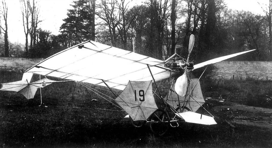
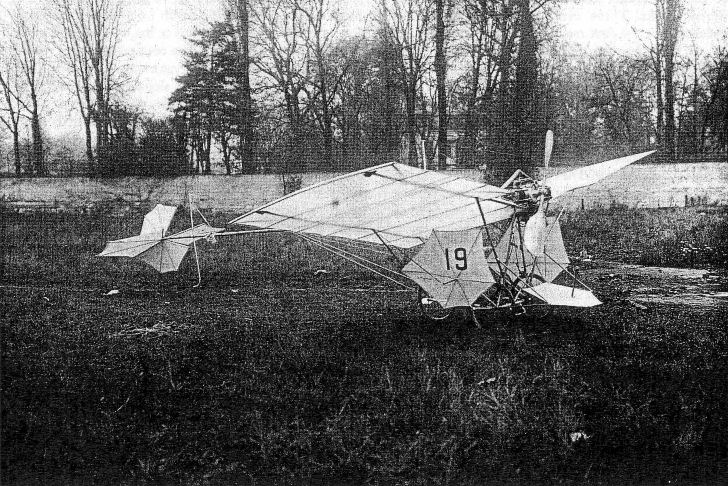
No 19: By the end of 1907 Santos-Dumont had completed his first real monoplane, a tiny tractor monoplane which he named Libellule (dragonfly); later he renamed it Demoiselle (another more common name for dragonfly, as well as for a young girl). It was built of bamboo and silk, weighing less than 60 kg: the rear fuselage was a single bamboo spar, with the small cruciform tail set on a universal joint at the end. The wings were nearly square in plan, with 2 spars and only 7 ribs on each side. The motor was perched at the center of the leading edge, and the pilot sat on a strap below, aft of the wings, between the wheels: a third wheel right behind him kept up the rear. Wing-warping was controlled by wires attached to the pilot's back. On each side of the machine, immediately outboard of the wheels, was a hexagonal surface coordinated with the swiveling tail: a small hexagonal forward elevator was set just ahead of the pilot's feet. After one crash, Santos-Dumont replaced the single propeller with 2 small ones, one on each side of the motor, driven on big sprockets by belts, one crossed; a 3-bladed fan cooled the motor. Santos-Dumont weighed only 49 kg ("without shoes and with gloves'"), and could easily take off in the little plane at Issy.
(Span: 5 m; length: 8 m; wing area: 9 sqm: gross weight: 110 kg including pilot and gasoline; 17-20 hp flat twin aircooled Dutheil et Chalmers driving a single Antoinette-style aluminum paddle-bladed propeller, or 2 Tatin built-up propellers)
No 19bis: But No 19 proved unsatisfactory, and was modified with the substitution of a 24 hp Antoinette mounted this time between the pilot's legs and driving a larger-diameter Tatin propeller through a wide belt and 2 pulley wheels, one large and the other enormous. The wings were enlarged to 13 ribs on each side, and the 3 hexagonal surfaces were removed; these changes did not improve the little machine.
No 20: Early in 1909 he introduced his next and most famous aeroplane, also called Demoiselle, and sometimes known also as Bebe or Joujou. The single tail-boom of No 19 proved too flexible and was replaced with a triangular frame made of bamboo poles fitted together through metal casings and braced with short metal struts. A third wheel at mid-length supported the tail. For this new machine Santos-Dumont designed and had Darracq build a 30 hp water-cooled flat twin; it was mounted above the pilot on the top wing, and the radiator tubes were wrapped around the upper boom. The Chauviere propeller was of constant chord.
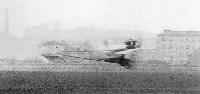
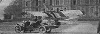
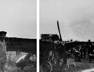
In March 1909 No 20 was damaged at Issy; it was repaired and taken to St Cyr - still today a small airfield west of Paris. It reappeared with a new Chauviere and new radiators, this time the tubing laid chordwise under each wing. The tailwheel was gone, replaced by a tall skid under the rear fuselage. A large cone-shaped tank appeared immediately behind the pilot. This version was sometimes referred to as Demoiselle II; in it Santos-Dumont flew the 8 km from St Cyr to Buc in 5 minutes to win a bet with Guffroy.
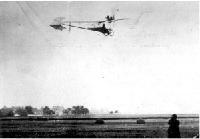
The Demoiselle was sometimes described as "flying like a butterfly;" it was sometimes also called the Infuriated Grasshopper. Very unstable and quick for its time, it allowed only the lightest pilots to fly it, and few did it well. Several were built at Santos-Dumont's factory, and he generously allowed the public access to his patents, so many more were built in garages and back yards. Some larger firms wanted to take advantage of his offer; he delivered an uncompleted No 20 to Dutheil et Chalmers as a model to build from. This may be the machine, seen in some photographs, fitted with a Dutheil et Chalmers flat twin early in 1910.
Though advertised at only 5,000 Francs, the Dutheil et Chalmers machine was never produced, and the machine delivered by Santos-Dumont was abandoned until it was recovered by Charles Dollfus and taken to the Musee de l'Air et de l'Espace, where it was restored and is now displayed. It features a horizontally-mounted steering wheel.
(Musee de 1' Air et de l'Espace aircraft - span: 6.4 m: length: 6.75 m; wing area: 10 sqm; take-off weight: 118 kg: top speed: 90 kmh; 25 hp Dutheil et Chalmers)
Earlier in 1909 the firm of Clement-Bayard became interested in the Demoiselle project, and the modified original Demoiselle was thus fitted with the 4-cylinder inline Clement-Bayard from the former Maurice Clement biplane, and tested unsuccessfully in September 1909. Since the engine was too heavy, Clement-Bayard made plans for mass production of the Demoiselle at 7500F each, 2,500 more than the projected Dutheil et Chalmers, though nearly 20.000F less than any other production aeroplane. The Clement-Bayard machines had all-metal tail girders and wooden wings, and were powered with 30 hp flat twins: still the aeroplanes were tricky and could only be flown by the lightest-weight pilots. It was unstable on all axes, with inadequate power and lifting surface. Sometimes the Clement-Bayard version was referred to as Santos-Dumont No 21.
Roland Garros, who became known as a Demoiselle pilot, and his friend Edmond Audemars, undertook unsuccessfully to build a Demoiselle copy. And Morane-Saulnier did the same in 1913, a 2-seater with a low-set Gnome and Morane wings.
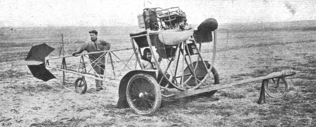
A Demoiselle ground trainer, in which the rear fuselage of a Demoiselle, complete with pilot's seat and overhead engine and propeller, was mounted inside a large semicircular track in which the whole device could rotate 90° in each direction, at the same time moving forward on a large 3-wheeled chassis.
But by this time the ingenious little Brazilian was beginning to suffer from the disease, probably sclerosis, that caused his early retirement and withdrawal from aviation. In 1914, already bitterly depressed and horrified by the War, through a misunderstanding he was accused of being a German spy. Enraged, he destroyed all his papers and returned to Brazil. In and out of sanitariums, he returned to Rio in 1928: a surprise welcome demonstration turned to disaster in front of him when the committee's big seaplane crashed in the harbor; in 1930 the British airship R101 was destroyed; his own country burst into revolution. Sick, and feeling guilty about his part in the development of aviation, on 23 July 1932 he hanged himself.
Показать полностью
Журнал Flight
Flight, January 9, 1909
THE FIRST PARIS AERONAUTICAL SALON.
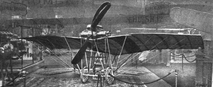
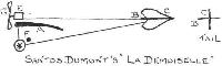
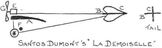
Santos Dumont's "La Demoiselle."
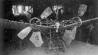
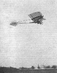
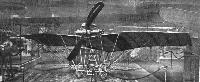
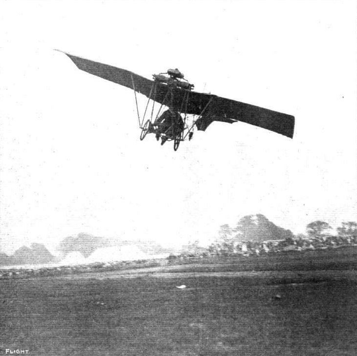
Besides being the smallest machine at the show, "La Demoiselle" hangs aloft by a wire like a toy butterfly so that few of the visitors noticed its existence. It is a monoplane having a twin cylinder engine mounted above the wings. The engine drives a two-bladed tractor-screw and the aviator sits beneath on a light saddle. The spread of the wings is only about 5 metres, and their surface only about 9 sq. metres. The total weight is only 67 kilogs., so that it can be very readily handled by one man; it has already achieved some short flights.
Flight, September 25, 1909
M. SANTOS DUMONT'S NEW ACHIEVEMENTS.
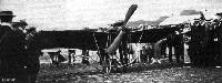
Santos Dumont Holds "Jumping Off" Record.
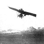
IT is a long time since M. Santos Dumont had a flying record standing to his name, but he has now secured the honour of being able to rise from the ground in the shortest distance. The official record of the Aero Club of France states that M. Santos Dumont rose from the ground after travelling 70 metres in 6 1/5 seconds, thus beating the record of Mr. Glenn Curtiss, who got up in 80 metres. The "Demoiselle" actually rose when only 40 metres had been covered, but it touched earth again, and 70 metres were traversed before the little flyer got clear away.
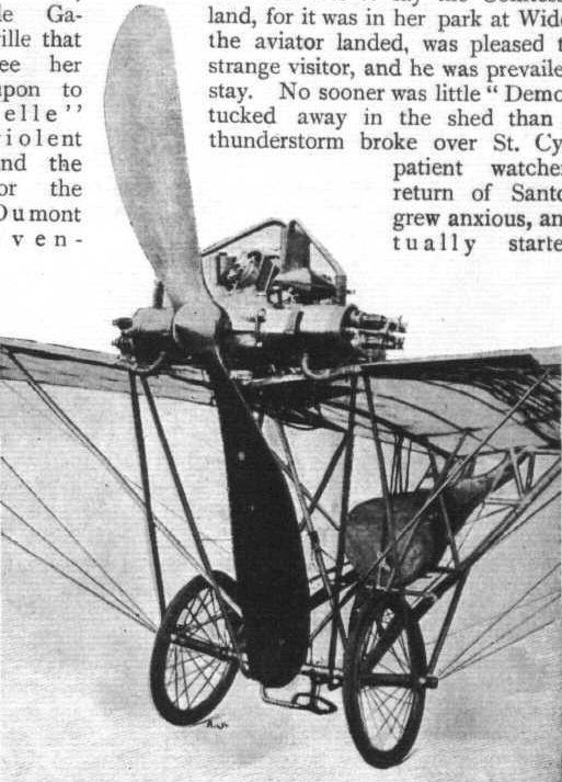
M. Santos Dumont had an interesting experience on the 17 th inst, which illustrates how it will be possible to visit one's friends by aeroplane when they become more reliable and more common. He started off from St. Cyr for one of his little excursions, but was so enraptured with the flight that he kept on until miss-firing of the motor reminded him that his petrol supply was limited. He then found he had lost his bearings, but seeing a house in the distance he determined to come down in the surrounding park. This was safely accom1ished, and needless to say the Comtesse de Galand, for it was in her park at Wideville that the aviator landed, was pleased to see her strange visitor, and he was prevailed upon to stay. No sooner was little "Demoiselle" tucked away in the shed than a vio1ent thunderstorm broke over St. Cyr, and the patient watchers for the return of Santos Dumont grew anxious, and eventually started searching the surrounding neighbourhood for tidings of him. Subsequently one of the sons of the Comtesse, who had seen Santos Dumont start, returned home, and was somewhat astounded to see him calmly sitting down at supper. The distance flown was about 17 kiloms., which was covered in about a quarter of an hour. On the previous day M. Santos Dumont made two flights, one from St. Cyr to Buc and back, and another in which he demonstrated the ability of his little machine to carry weights out of balance. A weight of about 40 lbs. was attached to one side of the frame, but in spite of this the flyer kept an even keel, and, moreover, maintained it when the weight was suddenly released. On Saturday last at St. Cyr M. Santos Dumont further demonstrated the stability of his machine by flying without holding the steering wheel, waving a handkerchief in each hand to show that he was not controlling the machine, which flew on as usual.
Flight, October 2, 1909
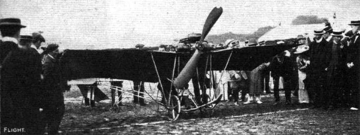
SANTOS DUMONT'S "DEMOISELLE."
DETAILS OF THE SMALLEST KNOWN FLYER IN THE WORLD.
ALTHOUGH the historic cross-Channel Bleriot is a close rival to it, there is no doubt but that the chief centre of interest in the exhibition now open in Paris is that corner of the Clement - Bayard stand on which reposes Mons. Santos Dumont's "Demoiselle," or, to give it the title it bears, "Le Santos No. 20." Partly all the world flocks round this monoplane because it is the smallest practical flyer which is known to have accomplished its primary object. But everyone also goes to see it in consequence of Mons. Santos Dumont's announcement of the free presentation of any rights he might maintain in connection with it, to the world at large. In connection with the exhibit, the designer has issued a printed circular for distribution, and in this he announces that whereas he had originally hoped that anyone could obtain these machines by having them built for themselves at a total cost of from some six to seven thousand francs (L240 to L280), yet he found that the prices charged by manufacturers for engines would inevitably increase that figure at the moment. The circular announces, however, that been made by him with Mons. Clement and Mons. Charron, whereby a thousand of these little voiturettes of the air are to be turned out at a reasonable price, and within a short period.
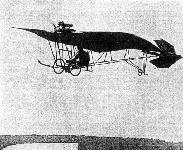
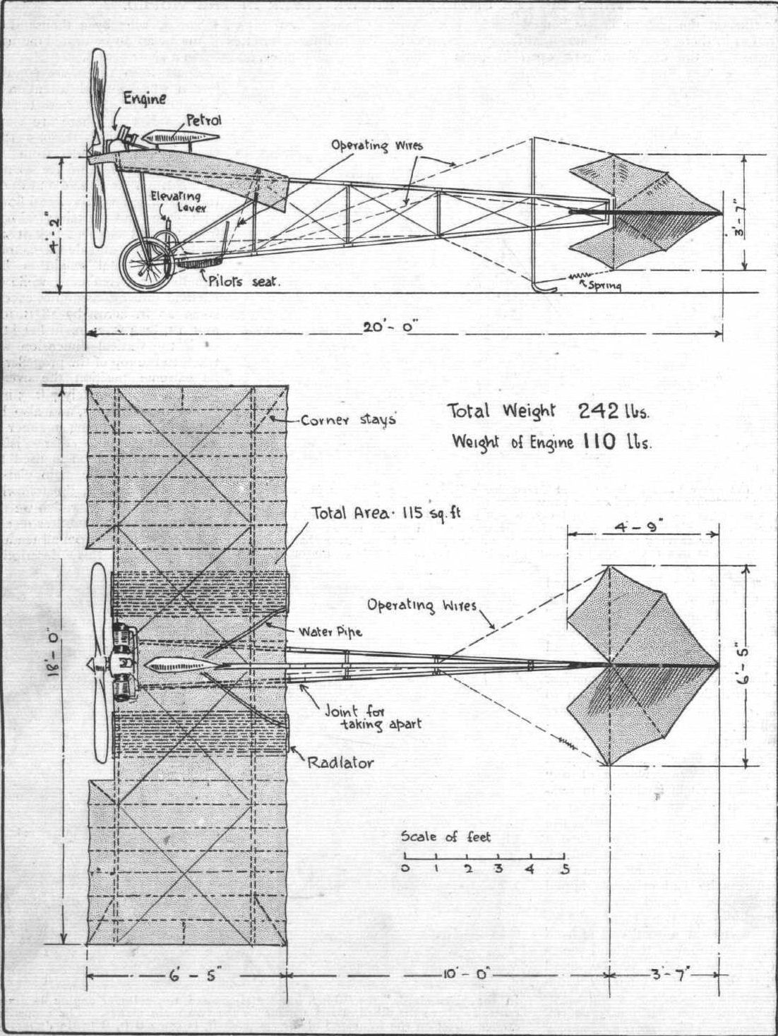
Apart from the more popular reason why so much attention is being devoted just now to the "Santos No. 20," there are many excellent technical reasons that warrant that attitude from all serious well-wishers of the science of flight. After all said and done, this machine has flown, and flown with ease and certainty almost from the first moment that it saw the light of day outside the factory, and yet its total weight is but 240 lbs. or thereabouts, while its external dimensions do not exceed some 20 ft. across by 18 ft. fore and aft, by 4 ft. 2 in. in height - of if the vertical dimension was taken to the top of the propeller in its extreme position the overall height is approximately 7 ft. 5 in.
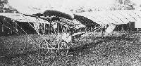
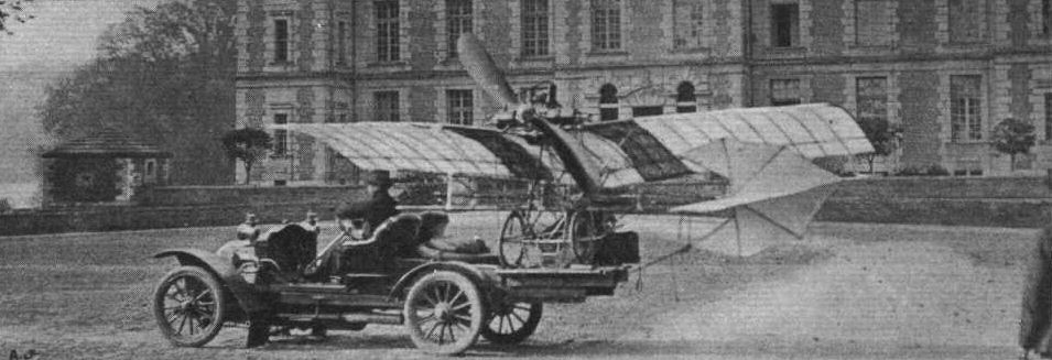
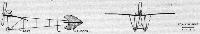
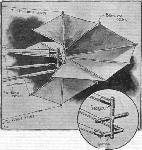
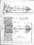
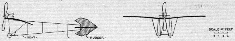
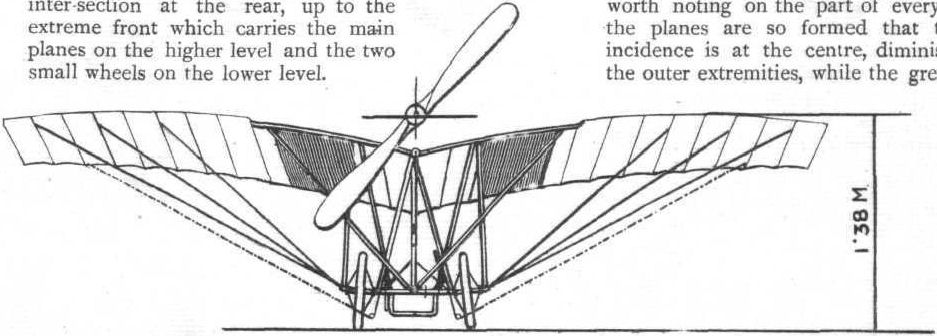
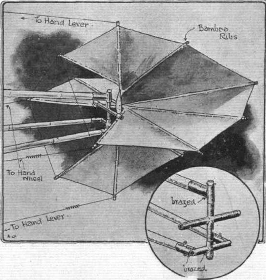
For these reasons, and also because of the cunning manner in which that not altogether satisfactory material bamboo is used for the chassis, for the main planes, and for the rudder the following, detailed description which we are able to give will doubtless receive a hearty welcome from all readers. Accompanying this description we are able to give a sheet of drawings of the type which we have already made peculiarly our own in this connection, besides another line drawing which comprises a front elevation of the complete machine and sundry photos that clearly demonstrate the nature of the framework as well as the manner in which the motor is carried upon it. The special drawing referred to has all the principal dimensions marked thereon, and as usual this comprises side elevation and plan. In addition to the photographs published herewith we would also remind the reader that four other views appeared in the last issue of FLIGHT, showing the machine in the air, being transported by motor car, and in respect to its important details.
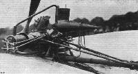
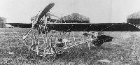
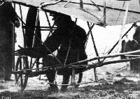
The Chassis.
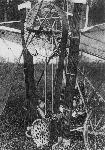
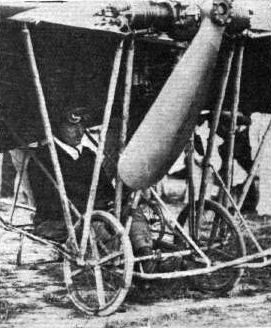
A main frame of girder construction is formed by three stout bamboos which are about 2 ins. in diameter at the thickest places, and are arranged two on a lower level with the other centrally above them. Inter-connecting them together are steel struts of oval section, and this main frame is approximately 16 ft. 5 in. from the point of intersection at the rear, up to the extreme front which carries the main planes on the higher level and the two small wheels on the lower level.
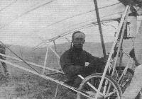
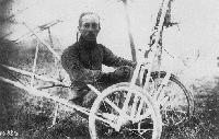
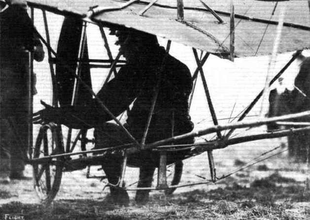
A practice is made in this machine of smoothing down all the bamboo knots, presumably to reduce their resistance, and of binding the bamboos between the knots so as to prevent splitting. All diagonal wires are, moreover, provided with neat little tighteners, none of which are more than an inch long. Our illustrations very clearly show the precise shape of the triangular girder frame, to which we have just referred, and also indicate the position and nature of the seat that accommodates the operator. This seat merely consists of a piece of canvas stretched across between the two lower main bamboos, the operator thus being placed quite low down in the chassis, and just aft of the two supporting bicycle wheels. Other features of the main frame are the provision of a special universal joint which carries the tail, and of a special vertical member fixed some three feet from the rear end, which not only serves to carry the wires which operate the elevator portion of the tail, but which has a runner formed at its foot to act in conjunction with the two wheels when the machine is resting on the ground. It will be observed that this runner is all that is required, inasmuch that as soon as the monoplane gets going the tail end lifts free of the ground before the fore portion rises.
A further important characteristic of the girder is that it is divided in the neighbourhood of the rear of the main planes, so that it can be taken apart without difficulty. Brass sockets are fitted for this purpose.
The Main Planes.
Two main transverse spars constitute the principal members of the two main planes, which are set at a dihedral angle to one another, in accordance with M. Santos Dumont's well-known beliefs on this subject. These spars are of ash, but are not of an even section throughout their entire length, being heaviest a few feet away from the dihedral angle, where they are about 2 ins. wide by about 1 1/8 ins. deep and tapering down to a bare inch in depth, though still retaining a width of a couple of inches where they are joined to the central bamboo. The front spar lies some 9 ins. behind the leading edge of the frame, while the rear one is about 12 ins. forward of the trailing edge, and the planes are otherwise built up with bamboo ribs fixed beneath the two main spars while the surfacing is double and is formed of silk.
A further feature of the construction of the planes is the employment of light bamboo corner-stays which save the employment of any heavy end-rib, and are thus well worth noting on the part of every designer. In shape, the planes are so formed that the angle of greatest incidence is at the centre, diminishing slightly towards the outer extremities, while the greatest camber is not as near the leading edge as usual, being barely in front of the centre.
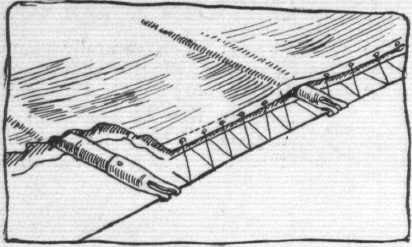
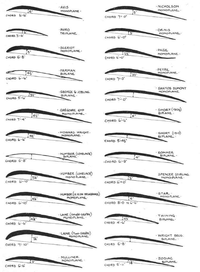
With a total span of 18 ft., and a chord of 6 ft. 5 ins., it will be observed that the total area of the planes is about 115 sq. ft., and that the aspect ratio is approximately 2.8. As regards the camber, this is roughly about 4 ins. Other constructional details that are of importance while still speaking about the main planes, include the following: - The leading and trailing edges are caused to be quite sharp, owing to the use of wires that are fitted to the ends of the rib; pockets are formed in the planes, owing to a line of sewing being run between the various ribs; and another unusual detail is that no wires are to be found above the planes, all wire diagonals being arranged between the surfaces.
The Tail.
As already briefly indicated, the tail moves as a whole and is pivoted on a universal joint for that purpose. This part of the machine in particular is commendable in design, and the construction is certainly preferable to other methods in common use, in which one of the elements of the tail is divided in order to allow for the movement of the other. As will be observed, the ball-and-socket joint lies some 10 feet behind the trailing edge of the main plane, and the motion of the tail upwards and downwards for elevating, as well as sideways for steering, is controlled by steel wires in the manner that can to some extent be followed in our special illustrations.
Both tail surfaces are quite flat, being free from camber, and are stretched upon bamboo ribs. The horizontal surface constituting the elevator is 6 ft. 5 in. across from tip to tip, and measures 4 ft. 9 in. fore and aft between its extreme points, while the vertical rudder surface has a similar shape, and an equal fore-and-aft dimension, but possesses a considerably less total area than the elevator.
Controlling Mechanism.
There are three principal means whereby the pilot can control the machine, apart from the switch-button, which is coupled up in the ignition system for the engine, and is fixed to the elevating-lever. The first of these is the elevating-lever, by means of which the tail is moved up and down, and this lever lies close to the right hand of the pilot, as may be seen in our illustration. Next should be mentioned the small hand-wheel, which lies on the left, this controlling the steering-gear inasmuch as it enables the rudder to be moved bodily backwards and forward sideways. And thirdly there is a lever lying against the aviator's back which enables him to warp the wings by leaning his body over to left or right as may be needed. Leaning to one side causes the rear edge of the wing on the opposite side to be flexed downwards, and thus causes that side of the machine to rise. It will be observed that there is no actual connection between the wing flexing and the tail control, which is a very important detail to be noted.
Another detail which concerns the controlling mechanism on "Le Santos No. 20" is that springs are introduced in the controlling wires for each of the steering systems so as to maintain them taut under all conditions.
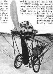
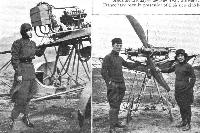
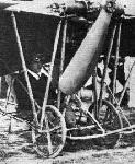
The Engine and Propeller.
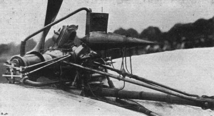
As regards the motor itself, this is of the twin-cylinder horizontal type with opposed cylinders. The bore and stroke are respectively 130 mm. and 120 mm., and an output of about 30 h.p. is available, with a total weight of some 110 lbs. Brass jackets are used for circulating the water around the cylinders, and the valves, which are all mechanically operated, are situated in the cylinder heads. Auxiliary exhaust-ports drilled through the cylinder-walls constitute an additional means of escape for the burnt gases, and the crank-shaft receives the propeller direct upon its front end, so that no additional fly-wheel is needed.
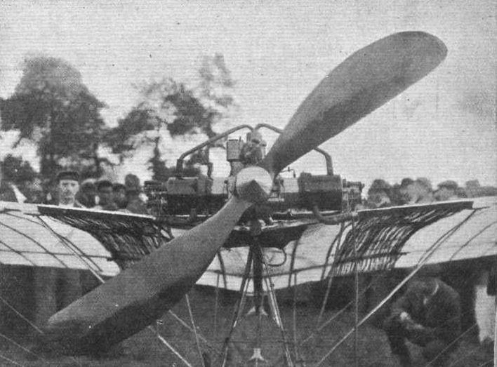
This engine is mounted upon the upper bamboo, and additional supports for it are provided between the cylinder-heads and the front transverse-spars of the main planes. It is, therefore, carried bodily up above the planes - indeed, at an unusually high altitude, and since the propeller is no less than 6 ft. 6 ins. in diameter, the blades consequently cut across the line of sight of the operator. The propeller, moreover, lies very close up to the leading edge of the planes.
Concerning the auxiliaries to the motor, a brass petrol tank of torpedo shape is fixed above the central angle of the planes, and the carburettor lies immediately beneath the motor, while a special type of radiator is used for cooling the water, and is placed on either side, as may be observed in our illustrations. This radiator is made in two sections, each of which extends the full width of the main planes, and is situated close underneath them. It is formed of very small tubes connecting a larger front tube with a larger rear tube, the small connecting tube being only about 1/8 th of an inch in external diameter; some hundred of these tubes are employed on each side, and they are made of copper.
Flight, October 9, 1909
FURTHER DETAILS OF SANTOS DUMONT'S No. 20
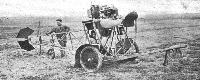
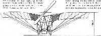
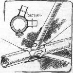
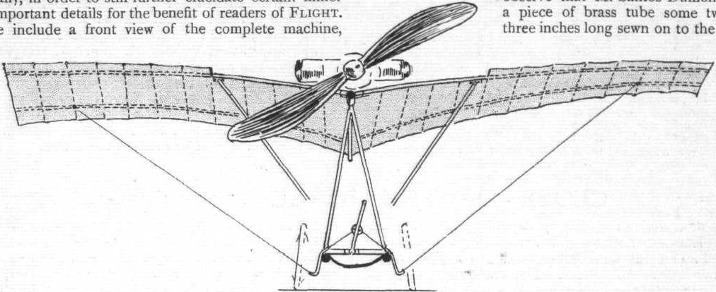
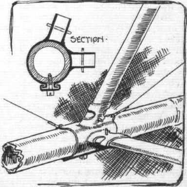
SUPPLEMENTING the very full illustrated description which we gave last week of the "Demoiselle," we now reproduce four further sketches which we have made specially, in order to still further elucidate certain minor but important details for the benefit of readers of FLIGHT. These include a front view of the complete machine, another showing the tail with its universal-joint, a third illustrating special fitments adopted for the tubular struts for the main girder, and the remaining sketch relating to the system of lacing adopted for the trailing edge of the main plane.
In the first of these illustrations two important points are brought out with special prominence. Firstly, the tubular stays which form the chief supports for the leading edge of the main planes, and secondly, the precise manner in which the operating-wires for warping the wings are run through small guide-tubes on either side of the aviator's seat. The centrally placed lever which lies behind the back of the pilot operates the wings as described last week, but it is interesting to observe that M. Santos Dumont has a piece of brass tube some two or three inches long sewn on to the back of his jacket, so that when he is seated in place the tube slips over the lever in question and enables him to rely upon a positive action when he leans over to the right or left. In the same sketch, too, may be observed the position occupied by the two chassis wheels.
As regards the tail, this in itself is constructed with a bamboo rim as mentioned last week, but the universal swivel is formed entirely of pieces of tube, in the use of which the inventor is very clever. The intermediate T-piece has one vertical arm that swivels in the brased sockets which couple up the main bamboos together, and the tail itself swivels upon the horizontal arm of the T-piece. Our sketch also shows the connecting-wires that pass to the hand-lever on the right and the hand-wheel on the left for elevating and for steering respectively, and also denotes the presence of the small helical springs that automatically take up any slack or allow for any contractions in the operating-wires.
It will be remembered that we spoke last week of the ignition-switch that is fitted into the steering-lever for enabling the engine to be stopped at a moment's notice if necessary. In addition to the three controls for the monoplane proper, it should also have been stated that the throttle-valve on the engine is coupled up to a pedal conveniently placed for the left foot. In this way the two engine-controls can be manipulated, although the operator's hands need never leave the even more important lever and wheel on which the evolutions of his flyer depend so greatly. Our other illustrations with their inscriptions readily speak for themselves, and hence no further reference need be made to them here.
Flight, March 12, 1910
THE SECOND OLYMPIA AERO SHOW.
AEROPLANES.
Santos-Dumont.
REPLICAS of the little "Demoiselle" monoplane built in France by Mons. A. Clement. A fully-illustrated description, with scale drawings, appeared in our issues of October 2nd and 9th last. It is fitted with a two-cylinder water-cooled motor, and the weight complete is about 110 kilogs. The overall measurements are 6.2 metres long and 5.'5 metres wide.
Flight, April 9, 1910
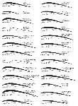
FLYER SILHOUETTES FROM OLYMPIA
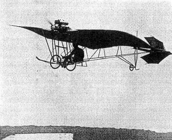
SANTOS-DUMONT "DEMOISELLE."
Leading Particulars of the Santos Dumont "Demoiselle"
General Dimensions.-Areas-Main planes, 108 sq. ft.; elevator, 12 sq. ft.; rudder, 7 sq. ft.
Lengths.-Span, 18 ft.; chord, 6 ft. 6 ins.; camber, 3 ins.; skid track, 3 ft. ; overall length, 21 ft.
Angle.-Incidence, 7 degs.; dihedral, 1 in 11.
Propeller.-Diameter, 6 ft. 6 ins.; pitch, 2 ft. 6 ins.
Engine.-32-h.p. Clement.
Weight.-Total flying weight, 530 lbs.; loading (all weight supported on main planes), 4.9 lbs. per sq. ft.
Speed of Flight.-40 m.p.h.
System of Control.-Warping of main planes, combined rudder and elevator.
Price.-L300.
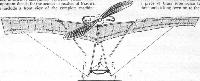
A COPY of the original Santos Dumont model, built with a steel triangular frame and other details of construction as described in FLIGHT, Vol. I, p. 604. One of the special features is the fitting of tubular radiators underneath the wings. The engine on this machine is a horizontal twin-cylinder Clement. The pilot sits underneath the wings. Wing warping is effected by a lever temporarily attached to the pilot's back by a strap. The pilot leans over towards the wing that has been raised by the wind gust in order to restore equilibrium.
In leaning in this direction he reduces the camber of the raised wing, and increases the camber at the extremity of the wing that is depressed, consequently the lift of the depressed wing becomes greater than that of the other wing.
Показать полностью