M.Goodall, A.Tagg British Aircraft before the Great War (Schiffer)
Deleted by request of (c)Schiffer Publishing
MARTIN-HANDASYDE monoplane No.2
The second monoplane was again built in the ballroom at Hendon and fitted with the original Humber engine. It was reported by The Aero, 24 May 1910 (p.407), to be nearly ready for trials in shed No. 12 at Brooklands.
The layout, similar to the earlier monoplane, was given greater wing area and the fuselage was strengthened with a three-ply wood covering throughout. The undercarriage was mounted on a single post, which also extended upwards, and together with kingposts at mid-span, provided anchorages for the bracing wires and pivots for the warping cables. The wheels, on separate half axles, were sprung by a laminated wooden spring. A tail-skid was supported by the rudder post, although the machine normally rested on the nose skid.
It is uncertain whether the machine actually flew with the Humber engine, but a 40hp side valve JAP had later been fitted and, on 15 June 1910, Martin lifted the machine off the ground. Tests continued until 30 July 1910 when it crashed heavily. It was not flown again until Martin took it out on 10 October 1910 and later that month was reported to have covered 300 yards. Graham Gilmour flew the aircraft on 2 November 1910, but disliked the Antoinette type separate hand wheel controls. He had these modified and retested the aircraft on 12 November 1910, when its identity was changed to No.3.
Power:
29hp Beeston-Humber four-cylinder inline car engine driving a Curva propeller.
40hp JAP eight-cylinder air-cooled vee.
Data
Span 32ft
Root chord 6ft
Tip chord 4ft
MARTIN-HANDASYDE monoplane No.3
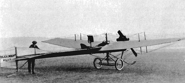
When the Antoinette type controls of No.2 were criticized by Graham Gilmour and changed to a central stick for the elevator, but with a wheel to control wing waiping, the rudder bar was retained. A large metal shield was attached to the stick to protect the pilot from the large amount of oil emitted by the JAP engine, which had auxiliary exhaust ports drilled in the cylinder walls. An extended fin and a rudder with squarecut trailing edge were now fitted.
Gilmour expressed himself as very satisfied with the controls and stability of the aircraft and the general strength of its construction. He seems to have 'acquired' the aircraft, his name appearing on the rudder and 'No.3 Martin-Handasyde' under the wings.
A wing tip was damaged when the machine was taken out by him on 8 November 1910, but it was flying well on the 12 November 1910. In the following weeks the engine was changed for the 35hp ohv JAP from the Bleriot 'Big Bat', and Gilmour flew with this for the first time on 11 December 1910. Sopwith tested the machine in the middle of February as a potential purchaser of the next machine already in the course of construction. Soon after this, in April or May, a 35hp Green was fitted for a short time, which involved the fitting of a sloping radiator behind the engine. By the 4 June 1911 a JAP engine had been reinstalled and pilot E.V.B. Fisher was still being blinded by the oil. The following day the machine was damaged by falling timber when Latham crashed on the roof of shed No.29, where the machine was housed. It is uncertain whether No.3 flew again, nevertheless it was still virtually intact in August 1914.
Power:
40hp JAP eight-cylinder side valve air-cooled vee driving a 7ft diameter propeller.
35hp JAP eight-cylinder ohv air-cooled vee.
35hp Green four-cylinder inline water-cooled.
Data
Span 32ft
Chord 6ft 2in reducing to 5ft at tips
Length 28ft
Area 175 sq ft
Area tailplane 19 sq ft
Area elevators 6 sq ft
Area rudder 8 sq ft
Area fin 8 sq ft
Weight 560 lb
MARTIN-HANDASYDE monoplane No.4B Dragonfly
Flight reported on 4 February 1911 (p.40), the advanced state of construction of a new two-seater with Gnome engine, purchased by Tom Sopwith, while The Aero 8 March 1911 (p. 193) referred to two machines in course of construction, the first to be fitted with a Gnome.
Sopwith was out on a Martin-Handasyde aircraft several times in February culminating with one flight on 22 February 1911, when the machine tipped on its nose, but this was on No.3 and No.4B seems to have been sent to Olympia for the Aero Show opening on the 24 March 1911, unflown. After the show closed, the machine was assembled in time for Sopwith to fly it on the 17 April 1911, but a wing was damaged when landing. Sopwith was soon to leave for his American tour and, with insufficient time to repair the Dragonfly before he left, he was forced to look elsewhere for a suitable aircraft to take. The machine remained with the firm and never became Sopwith's property.
The Gnome was of inadequate power and was replaced by an Antoinette provided by Hubert Latham, who became interested in the aircraft during his visit to Brooklands in May.
The new engine was installed and Radley tested the aircraft on 14 June 1911, followed by Morison on 19 July 1911 after the wing had been reconstructed; Gilmour, Fisher and Hamel also flew the aircraft in July but, on 23 July 1911, Morison crashed badly near the sewage farm and the machine was not rebuilt. There is no evidence that a second machine of the same type was built.
No.4B followed the general pattern of its predecessor, but was larger for passenger work. The undercarriage still consisted of hinged half axles connected to a sliding central fitting, but rubber cords in tension replaced the laminated wooden spring used earlier.
Power:
50hp Gnome seven-cylinder air-cooled rotary.
65hp Antoinette eight-cylinder water-cooled vee.
Data
Span 37ft
Chord 6ft (average)
Length 33ft
Area 240 sq ft
Weight 800 lb
Speed 60mph
Price .1,100
Data for aircraft with Gnome
P.Lewis British Aircraft 1809-1914 (Putnam)
Martin Handasyde No. 2
The second Martin-Handasyde monoplane was a larger version of the No. 1 and was constructed during 1909. A 35 h.p. J.A.P. engine was fitted and the machine occupied the first hangar to be built at Brooklands, where it was flown subsequently by H. P. Martin.
Martin-Handasyde No. 3
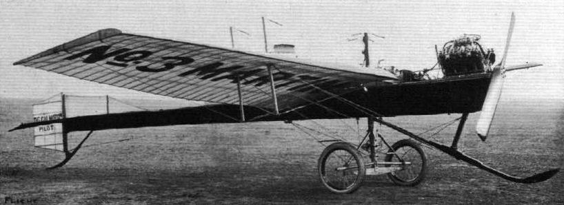
During May, 1910, Martin and Handasyde completed their No. 3 Monoplane at Brooklands. In appearance there was a very strong resemblance to the successful French Antoinette design, and the newcomer was as equally refined and elegant a product. The machine was a single-seater and was fitted with the 65 h.p. Antoinette engine. Weight and head resistance were kept to the minimum by the provision of a very slim fuselage, whose strength was maintained by the use of wood covering. A triangular section was used, the pilot's position being very exposed owing to the slenderness of the fuselage. His view, however, from his seat at the rear of the trailing-edge was comparatively good. Protection from the slipstream was provided by the rather clumsy expedient of fitting a vertical shield at the top of the control column, thus destroying at the same time some of the streamline properties of the machine which the designers had striven to achieve.
The undercarriage was a very strong unit carried mainly on a stout central support through the fuselage. Warping lateral control was fitted, and the tail unit consisted of the normal rudder and split elevators attached to fixed fin and tailplane.
H. P. Martin accomplished several good straight flights at Brooklands on the machine during November, 1910, and the No. 3 Monoplane became a very successful flyer in D. Graham Gilmour's hands. The Antoinette engine was succeeded by a 40 h.p. J.A.P. in 1911, and a 35 h.p. Green was also installed temporarily, but was removed in favour of the J.A.P. The No. 3 finally took Gilmour to his death on 17th February, 1912, when it broke up in the air and crashed while flying over Richmond Park at 400 ft. in bumpy weather.
SPECIFICATION
Description: Single-seat tractor monoplane. Wooden structure, fabric covered.
Manufacturers: Martin and Handasyde Ltd., Trinity Works, Camberwell.
Power Plant: 65 h.p. Antoinette, 40 h.p. J.A.P., 35 h.p. Green.
Dimensions: Span, 32 ft. Length, 28 ft. Wing area, 175 sq. ft.
Weights: Empty, 560 lb.
Performance: Maximum speed, 60 m.p.h.
Martin-Handasyde No. 4B
The 4B tractor monoplane was a two-seat version of the No. 3 and was built to the order of T. O. M. Sopwith, being displayed at the 1911 Olympia Show. Named Dragonfly, it was powered by the 50 h.p. Gnome engine, which was mounted in a triangular fuselage covered with three-ply wooden panels. Other engines fitted were the 40 h.p. J.A.P., the 40 h.p. Clerget and the 65 h.p. Antoinette. The machine was flown successfully at Brooklands by Sopwith and also by D. Graham Gilmour and C. Gordon Bell. Span, 37 ft. Length, 33 ft. Wing area, 240 sq. ft. Weight empty, 800 lb. Maximum speed, 60 m.p.h. Price, ?1,100.
Журнал Flight
Flight, March 25, 1911
THE MARTIN.HANDASYDE MONOPLANE.
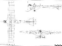
ANYONE first glancing at the Martin-Handasyde monoplane No. 3, or at the accompanying illustrations thereof, might be pardoned for supposing it to be an Antoinette; no intelligent observer familiar with the details of the Antoinette machine, however, could possibly fail to regard the Martin-Handasyde as anything but an original design after a few moments' thought. Where, to take only the popular aspect of the case, are those hand-wheels outside the body that pilots of the Antoinette monoplane manipulate so dexterously in windy weather? Then again, this is a much smaller machine and it is supported on an under-carriage quite like the Antoinette at a distance, but totally dissimilar in detail when examined at close quarters. Moreover, not only is the machine supported on this under-carriage, but it balances about the axle when the pilot is not on board. The engine is situated rather far forward and the propeller is, as a matter of fact, 3 ft. 8 ins. from the front edge of the planes. The weight of the engine has therefore sufficient leverage to balance the weight of the tail. Taken on its broad lines, however, it is presumably correct to say of the Martin-Handasyde monoplane that it belongs to the Antoinette type.
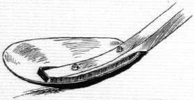
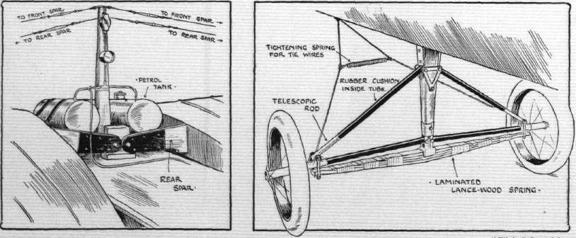
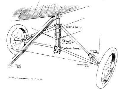
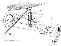
It has a boat-like body covered with wood, and in the bows thereof is mounted the 40-h.p. Jap engine with which the machine is at present equipped. Direct-coupled to the crank-shaft is a 7 ft. two-bladed propeller, which is protected against damage in rough landing by a skid jutting out from beneath the body and provided with a spoon-like foot. This skid, although strong, is flexible and bends noticeably when it comes in contact with the ground. Its spoon-shaped foot is formed by a sheet of steel hammered into shape and fastened to the end of the skid as shown in an accompanying sketch. The under-carriage itself, which this skid adjoins where it springs from the body, is of particular interest on account of the use of a divided tubular steel axle, reinforced and suspended by a laminated leaf-spring of lancewood. The constructional details of this interesting feature are well illustrated by an accompanying sketch, where it will be observed that each wheel is mounted on a half-axle hinged at its inner end to the lower extremity of the central mast that forms the principal upright of the machine. Bridging this joint is the laminated construction of lancewood that forms the principal member of the suspension. At the centre it rests in a channel bracket and its extremities engage with shackles that are hinged to the axle. Thus mounted, each wheel is free to rise and fall independently, for it will be observed that the diagonal strut, which forms a subsidiary member in the bracing, is telescopic; incidentally it is fitted with a rubber cushion inside the tube, which comes into action in emergency. Equally ingenious is the bracing of the axle fore and aft by wires that are linked together with a tension spring so arranged as to automatically keep them taut. This detail is likewise illustrated in the same sketch.
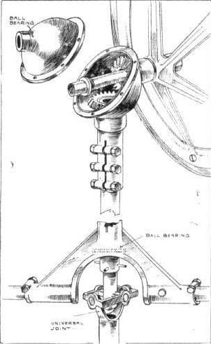
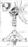
Above the body of the machine at this point, the mast carries the guy wires to the front and rear spars of the wings, and as the rear spars are hinged to the frame to facilitate warping, their guy wires are supported on a pulley so as to automatically adjust themselves to the warping movement. The operation of wing warping is effected by turning a steering-wheel mounted on an axis at right angles to that of an inclined column situated immediately in front of the pilot's seat. On the wheel-spindle is a small drum, round which is the warping wire leading to a pivoted cross-beam mounted on the central mast below the body. In order to increase the leverage, a block and tackle gear has been ingeniously introduced into the cable, as shown in an accompanying sketch. Fixed to the pivoted cross-bar is a chain-wheel engaging with which is a chain that has its extremities fastened to the wires leading to the rear spars of the wings. There is, of course, a very considerable tension on these wing-warping wires arid consequently no tendency for the chain to fall off the wheel, but a light guard, not shown in the sketch, is fitted in practice.
Moving the steering-wheel and the column on which it is mounted bodily to and fro operates the elevator, which is formed by two triangular flap extensions of the fixed horizontal tail-plane. The triangular shape of these planes gives room for the free movement of a rudder-plane mounted vertically between them, and, like the elevator, forming an extension of a fixed tail-plane. The rudder is operated by foot through the agency of a pivoted bar.
Of the wings themselves, it is interesting to remark that they each weigh 70 lbs. complete and are very strongly constructed, in spite of the fact that the spars by which they are attached to the body have the appearance of being very light. Inside the wings themselves, however, these spars are of T-section, 2 1/2 ins. in width and 7 ins. in depth. In addition to their top and bottom guy wires, the wings are also stayed by wires leading forwards to the projecting skid. The camber of the wings varies from the shoulder to the tip, the chord having a positive angle of incidence of about 5° adjacent to the body and being horizontal at the outer extremities. The thickness of the plane at the shoulder is 8 ins., but diminishes 2 1/2 ins. at the extremities and the chord itself also diminishes from 6 ft. to 5 ft., although this latter change is brought about more or less abruptly by obliquely cutting away the trailing edge from a point about 5 ft. from the extremities.
 |
M.Goodall, A.Tagg - British Aircraft before the Great War /Schiffer/
|
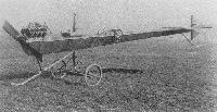
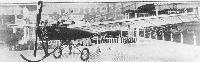
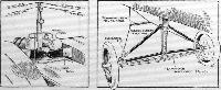
| Martin-Handasyde monoplane No.2, built at Hendon and tested at Brooklands, was much like an Antoinette including the control system.
|
 |
M.Goodall, A.Tagg - British Aircraft before the Great War /Schiffer/
|
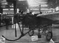
| This view of the fuselage of No.2 shows the Antoinette-type controls and the side valve JAP engine in use in 1910.
|
 |
Журнал - Flight за 1911 г.
|
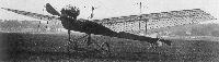
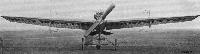
Side view of the Martin-Handasyde monoplane. No. 3.
Martin-Handasyde monoplane No.3 was the previous machine converted to a control stick with wheel for warping and was finally powered by an OHV JAP engine.
|
 |
Журнал - Flight за 1911 г.
|
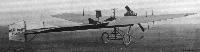
| General view from in front of the Martin-Handasyde monoplane, No. 3, showing the forward bracing of the wings to the skid.
|
 |
P.Lewis - British Aircraft 1809-1914 /Putnam/
|
| Martin-Handasyde No. 3.
|
 |
Журнал - Flight за 1911 г.
|
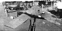
| General view of the Martin-Handasyde monoplane from behind, showing the bracing of the wings. The plate in front of the control-wheel is a shield to protect the pilot from the oil that is thrown out by the engine.
|
 |
P.Lewis - British Aircraft 1809-1914 /Putnam/
|
| The Martin-Handasyde 4B monoplane. A typical example of the Antoinette type, but full of original detail in design.
|
 |
M.Goodall, A.Tagg - British Aircraft before the Great War /Schiffer/
|
| Martin-Handasyde monoplane No.4B Dragonfly at Olympia in March 1911 was fitted with a Gnome engine later replaced by an Antoinette.
|
 |
Журнал - Flight за 1911 г.
|
| UNDER-CARRIAGES AT OLYMPIA. - The Martin-Handasyde axle and forward skid.
|
 |
Журнал - Flight за 1911 г.
|
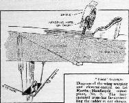
| Diagram of the wing-warping and elevator-control on the Martin-Handasyde monoplane, No. 3. The foot-operated cross-bar for controlling the rudder is not shown.
|
 |
Журнал - Flight за 1911 г.
|
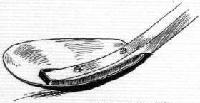
| Sketch of the spoon foot on the skid of the Martin-Handasyde monoplane, No. 3.
|
 |
Журнал - Flight за 1911 г.
|
| Sketches illustrating the attachment of the wings to the body, and the details of the undercarriage supporting the body of the Martin-Handasyde monoplane, No. 3.
|
 |
Журнал - Flight за 1911 г.
|
| Under-carriage of the Martin-Handasyde monoplane.
|
 |
Журнал - Flight за 1911 г.
|
| The Martin-Handasyde Control Gear.
|
 |
Журнал - Flight за 1911 г.
|
| UNDER-CARRIAGES AT OLYMPIA. - A comparison in tail skid construction.
|
 |
P.Lewis - British Aircraft 1809-1914 /Putnam/
|
| Martin-Handasyde 3
|
 |
Журнал - Flight за 1911 г.
|
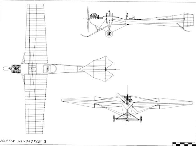
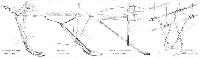
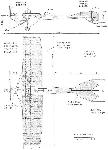
| MARTIN-HANDASYDE MONOPLANE, No. 3. - Plan and elevation to scale.
|