Журнал Flight
Flight, December 18, 1914.
EARLY AMERICAN STABILITY BIPLANES.
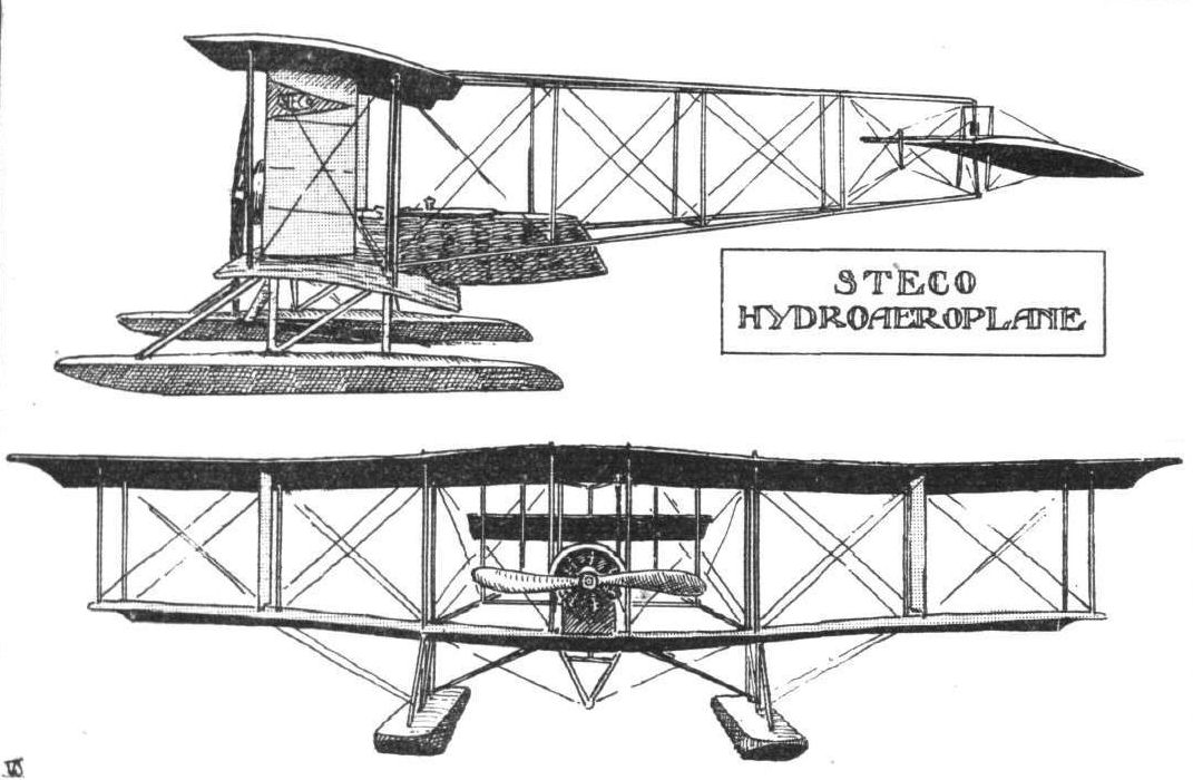
Two interesting examples of early attempts at stability aeroplanes hailing from America are the Steco and Carey biplanes, illustrated by the accompanying sketches, and incidentally it may be noted that it is claimed for both these machines that they circumvent the Wright aeroplane control patents. The Steco biplane was designed during the latter part of 1910, a favourable verdict having been expressed by the late Octave Chanute, to whom the drawings were submitted. In the spring of 1911 the machine was completed, but owing to the lack of a suitable motor no actual tests were made. It was not until the autumn of 1913 that a 50 h.p. Gnome engine was obtained, and as it was decided to test the machine over water a pair of Burgess floats were ordered. The machine was then dismantled and taken to the Stevens hangar on Lake Michigan at Chicago, where it was re-assembled. The first test flights were made last July, under the pilotage of Ralph S. Stevens, with entirely satisfactory results, the machine flying well with two up. Trial flights are still being carried out, but the experiments are somewhat hampered by bad weather. This machine is a tractor biplane of the nacelle and outrigger type, and is, therefore, bearing in mind the date of design, one of the forerunners of the now popular tractor biplane. Natural stability, longitudinally and laterally, is obtained by virtue of the peculiar formation of the planes, which, it is stated, is an adaptation of the principles of the Zanonia leaf that have also been embodied in the Dunne, Etrich, Handley Page, and other machines, only in the case of the Steco biplane they take a different form. The main planes are of rigid construction, and, as will be seen from the top view in Fig. 1, have a maximum gap in the centre and a minimum gap at the tips. In other words, both the top and the bottom planes are arched in the centre for about two-thirds the span, whilst the remaining portions at the tips are parallel and set at a dihedral angle. The top plane is set a little in advance of the lower one, and also has a slightly-increased angle of incidence. The planes are built up on more or less orthodox lines, upper and lower planes being separated by eight pairs of struts, and extending rearwards form from the second rear struts; from the centre are four outriggers carrying the tail plane. The top and lower pairs each converge to a point where they are attached to a single vertical strut, which carries the tail plane. This latter is, perhaps, the most interesting feature of the whole machine, for it is the only controllable surface employed in the steering of the machine in any direction. It is universally mounted on the aforesaid vertical strut in such a manner that it can be rocked in any direction longitudinally and laterally, and thus acts both as elevator and rudder, and incidentally as balancing plane. These combined movements are obtained by means of a single control lever, somewhat similar to a bicycle handle-bar, a forward or backward movement of which causes the machine to descend or ascend respectively, whilst turning it to the right or left steers the machine in those directions. In fact, tilting the control lever in any direction will cause a similar directional tilting of the plane, so that its movement in performing the functions of steering are such that it automatically compensates the banking of the machine when turning, thereby serving the same purpose of the movement of the vertical rudder covered by the Wright patent. Normally the tail plane is adjusted so that the machine will fly straight ahead when the engine is running, and will automatically assume its minimum gliding angle downwards when the engine is stopped.
Working automatically in conjunction with the tail plane are two vertical surfaces mounted one between each of the second pair of interplane struts from the wing tips. These two surfaces may be likened to check valves, for, co-operating with the formation of the planes at the outer ends, they maintain the correct banking angle when a turn is being made and prevent the machine from side-slipping outward for want of sufficient banking, and inwards through over-banking. They are hinged so that they can swing freely in an outward direction, but not inwards. When, therefore, the machine tends to side-slip outwards, the outer vertical surface acts as a brake to the movement in this direction, and assisted by the wing-form and relative dihedral angles, creates an additional lift on that side of the machine, which assumes its correct lateral angle for turning. The inner vertical surface is neutral because it is free to swing with the outward motion of the machine. A downward or inward side-slip is similarly checked.
As regards the rest of the machine, there is little at variance with usual practice. The 50 h.p. Gnome engine is fixed in the nose of a coracle-like nacelle mounted on the top and in the centre of the lower plane, passenger and pilot being seated in tandem. The two floats are set 11 ft. apart, and are connected to the lower plane by four struts each, with diagonal cross-struts to the centre. The principal dimensions of the Steco hydro-biplane are as follows :- Span, upper 41 ft. 8 ins.; lower 36 ft.; chord, 6 ft. 2 ins.; supporting area, 464 sq. ft.; area of tail plane, 74 sq. ft.; overall length, 31 ft.; weight, empty, 1,320 lbs.; speed, 50 m.p.h.
<...>