Журнал Flight
Flight, April 16, 1915.
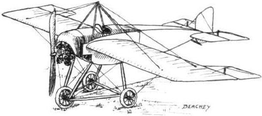
THE BEACHEY EXHIBITION MONOPLANE.
LINCOLN BEACHEY, America's most daring "stunt" flyer, who met his death just recently whilst giving a looping exhibition at San Francisco, had only shortly before got out the designs for a neat little monoplane which he intended to use in his future exhibitions, and two of these machines were being built at San Francisco. Most of the details of design were worked out by Mr. W. S. Eaton, special attention having been given to the quick assembling and dismantling of the machine. By the use of specially designed fittings both operations should be accomplished within 30 minutes.
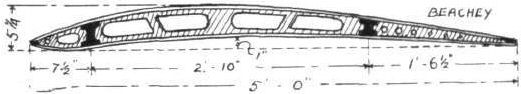
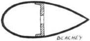
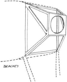
The wings, of the rigid non-warping type, having a Morane-Saulnier plan form, are in two 12-ft. sections and perfectly straight; that is, they have no dihedral angle. The wing section employed has been calculated from N.P.L. data to give speed; the maximum and minimum camber are 5 1/4 ins. and 1 in. respectively, and the under portion of the leading edge is slightly turned up as in the Nieuport wing section. Spruce is employed for the main spars, which are of I section tapering towards the outer extremities. The front spar is located 7 1/2 ins. from the leading edge, which is of wood, and the rear spar is 1 ft. 6 1/2 ins. from the trailing edge, which consists of steel tubing, except for a wood portion where the balancing flaps are hinged. The main ribs, spaced 16 ins. apart, are built up as shown in one of the accompanying sketches, of spruce flanges and cut-out fillers bored for lightness. Between each main rib are wood battens running from leading to trailing edge, whilst from the front spar to the leading edge a false rib is placed between the main ribs and the battens, which thereby greatly strengthens the front portion of the wing. The wings are internally braced with steel cable, and covered with Irish linen doped with Christofferson varnish. The attachment to the body is by means of quick detachable clamps, whilst the external bracing is by extra heavy steel cable, the top cables being attached to a pyramid of four steel streamlined struts mounted on the body above the pilot's cockpit, and the under cables are attached to the landing carriage.
Hinged to the outer extremities of the rear spars are two balancing flaps, each measuring 4 ft. on the hinging edge, 3 ft. 6 ins. on the trailing edge, by 2 ft. 3 ins. chord. They are constructed of tubular steel and spruce, the former for the outer frame and the latter for the attaching edge and ribs. These flaps are inter connected, and are operated by a Curtiss type shoulder yoke, the control wires being carried in tubing placed within the wing along the rear spar. The tail planes consist of a horizontal stabilising surface in two portions, each measuring 3 ft. 6 ins. by 2 ft. 6 ins., one mounted either side of the body, and two elevator flaps (exactly similar in shape and size to the balancing flaps) hinged to the trailing edge of the stabiliser, and a partly balanced vertical rudder in between the elevators. The latter are operated by a to-and-fro motion of a vertical column, upon which is mounted a wheel actuating the rudder. The section of the stabiliser is similar to that of the wing, only, of course, reduced in proportion.
The body, which is 12 ft. 9 ins. in length, is divided into two portions fore and aft. The front portion, containing the pilot, engine, wings, undercarriage, &c, measures 5 ft. 9 ins., with a maximum depth and width of 2 ft. 3 ins. The rear portion, measuring 8 ft., tapers to a horizontal knife edge at the rear, where it also narrows somewhat. Both sections are built up on more or less usual lines with four longitudinals tapering towards the rear and streamlined connecting struts, all cable braced. These two sections are connected by very strong quick detachable joints. The nose of the body has an aluminium covering which forms a cowl over the engine - an 80 h.p. Monosoupape-Gnome - and a turtle back, in which is the pilot's cockpit, along the forward section of the body. The reason for streamlining the body struts is that should it be found necessary the covering on the after portion of the body can be removed, leaving the latter open as on the Bleriot. The engine is supported in a specially constructed steel bearer, mounted on the nose of the body. A 7 ft. 9 in. tractor screw, with 7 ft. 4 in. pitch, is direct coupled to the engine, and the fuel tanks are placed under the engine cowl. In front of the cockpit, which is well padded, is a small transparent wind shield that greatly reduces the wind pressure on the pilot's face. Of the three-wheeled type, the undercarriage is exceedingly strong; no shock-absorbing devices are employed, the necessary resiliency being provided by the 20 in. by 4 in. tyres fitted to the wheels. The latter are arranged two 5 ft. apart under the pilot's cockpit, and one 3 ft. 10 ins. in advance of the others. All three are connected by a triangular frame of steel tubing, whilst two pairs of steel streamlined struts connect the latter with the body, the whole carriage being cable-braced.
The general dimensions of the Beachey monoplane are: Overall span, 27 ft. 6 ins.; span of wings, 26 ft. 6 ins.; chord, 5 ft.; supporting area, 110 sq. ft.; overall length, 18 ft.; weight empty, 520 lbs.; speed, 45-100 m.p.h.; gliding angle, about 1 in 5.