Описание
Страна: Германия
Год: 1920
G.Haddow, P.Grosz The German Giants (Putnam)
Staaken E.4/20
The all-metal Staaken E.4/20 four-engined monoplane, the last creation of the dying R-plane industry, was visible proof of the progress which the Germans had made in the design and construction of large all-metal aircraft during the war years. Standing on its own merit, the Staaken E.4/20 was truly the world's first modern transport aircraft, and its functional lines belie the fact that it was built as early as 1919-20.
The construction of the E.4/20 was begun in May 1919 at the direction of Alfred Colsman, general manager of the Zeppelin combine; one of the stipulations was that the fully-loaded aircraft should be able to remain airborne on the two engines. It was planned to place the E.4/20 in service as a commercial passenger transport between Friedrichshafen and Berlin. There can be no question that the design of the E.4/20 owed much to the all-metal monoplane bombers which Staaken was developing under Idflieg contract in 1918. Although strictly a transport aircraft, the E.4/20 could not have differed appreciably in layout from these projects. With an additional engine mounted in the nose, the E.4/20 could well have been the Staaken five-engined bomber design described by von Bentivegni in 1919.
As related previously, Dr. Adolf Rohrbach, an engineer who had been very active in the development of metal construction techniques at Dornier, was transferred to Staaken in 1916-1917 to apply his talents to all-metal R-landplane design. Dr. Rohrbach had been hand-picked by the head of the Staaken R-plane Construction Department, Prof. Baumann, to be his successor, and this he became in 1919, when he assumed technical leadership of the Staaken organization.
Viewed in relationship to the wood and fabric civil aircraft of the immediate post-war era, the E.4/20 was indeed a pioneering achievement of the first magnitude. With the exception of refinements in detail, the construction techniques were very similar to those common today. The airframe was built wholly from specially formed duraluminium profiles riveted together and covered with a thin-riveted duraluminium skin. This construction method was simply an extension of the process devised by Dornier which found expression in a very modern airframe.
The most striking feature was the large cantilever wing, which had a wingspan of 31•0 metres (101,7 feet) and featured a thick wing section based on the aerodynamic investigations of Professor Junkers. The wing was built around a single riveted box-spar of very large dimensions; its width constituted one-third of the wing chord, and at the wing roots its depth was 1•5 metres (4'9 feet). The leading and trailing edge wing sections and engine bearers were attached to this massive central spar. The leading-edge skin was formed of 4 mm. thick duraluminium sheet, the box-spar covering 3 mm. thick and the trailing edge 2 mm. thick, while the remainder of the wing was covered with fabric. The box-spar was pierced by an oval opening which permitted a mechanic to crawl behind the engines, although it would seem difficult to perform extensive in-flights repairs in the small space provided.
The wing loading-extremely high for its day-was 80 kg./sq.m., a value almost double that of a comparable monoplane, the Dornier Rs.IV (46•5 kg./sq.m.). Because practical experience with such high wing loads was not available, it was deemed prudent to provide supplementary wing-bracing cables primarily as a safety feature. However, the wing structure had been calculated to withstand the dynamic flight loads without any additional supporting cables or struts.
The four 245 h.p. Maybach Mb.IVa engines were mounted on a robust framework extending from the central box-spar, and their outline was neatly cowled into the wing. The engines were placed ahead of the leading edge in a manner shown feasible by tests conducted at the Dornier works in 1917. Fuel was contained in two large tanks placed in the leading edge between the engines and four smaller tanks situated in the trailing-edge wing section.
The fuselage consisted of fourteen rectangular frames attached at each corner to four angle-shaped longerons running the whole length of the fuselage. The duraluminium skin riveted to the fuselage framework provided the required stiffness in the absence of diagonal bracing between adjacent frames. In the rear of the fuselage light metal traps riveted across the corners of each frame gave torsional stiffness. The two frames which supported the wing were solidly constructed of riveted box-sections. To prevent buckling and resonance vibrations of the skin, light reinforcing stringers were riveted to the inside of the skin, giving an appearance of extra longerons.
The open pilots' cockpit was located atop the fuselage slightly forward of the wing leading edge and commanded an excellent view. At a later date the nose decking was lowered and a fully-enclosed pilots' cabin with Cellon windows was installed. A door in the nose allowed passengers to enter the fuselage, which could accommodate twelve to eighteen persons seated two abreast. A large mail compartment, toilet, separate wash-room and luggage space were located in the rear of the fuselage.
The tail assembly consisted of a fixed tailplane and fin of cantilever construction covered with duraluminium sheet. The elevator and rudder were aerodynamically-balanced and covered with fabric. The ailerons, of very small chord, were fully balanced and hinged to the ends of the wing spar.
The twin wheels were supported by a very simple undercarriage made up of one heavy strut, which contained the shock absorber and was attached to the wing spar between the engines. Two horizontal struts were affixed to the lower corner of the fuselage and converged at the axle.
While the aircraft was under construction the Inter-Allied Control Commission inspected the framework and permitted Staaken to complete the E.4/20 in spite of the prohibition clauses in the peace treaty. The Commission felt that they could not pass judgement on the aircraft’s military potential until it was completed and had performed flight tests. Naturally, Allied engineers attached to the Commission followed the assembly progress with a high degree of interest.
The E.4/20, completed 30 September 1920, performed a number of exceedingly promising flights with test pilot Carl Kuring at the controls. During one flight made under optimum conditions the aircraft was clocked at 225 km.h., an unheard-of speed for an aircraft of that size. It was found, however, that it was not possible to maintain flight on two engine as had been hoped. Further test flights were prohibited by the Inter-Allied Control Commission, which was not convinced that the E.4/20 did indeed have military potential and as such violated the treaty stipulation. Director Colsman wrote that the Commission also refused the E.4/20 to be sold or given away, leaving Staaken no recourse but to scrap the machine. It was Colsman's opinion that the Commission acted as it did in order to financially cripple the Zeppelin concern and destroy its ability to perform further work in this field. This action can be understood in the light of the Commission's charter to prevent the resurgence of a military aircraft industry in Germany. With its superb performance, the E.4/20 could have been a bombing weapon to fear.
The aircraft was scrapped on 21 November 1922, destroying in the process the forerunner of the modern transport aircraft. The significance of the E.4/20 in future aircraft development has been largely forgotten, and it is a pity that Rohrbach and Staaken never had a chance to develop its full peacetime potential. To Dr.-Ing. Adolf Rohrbach must go the credit for having conceived an aircraft formula which virtually all large transport and military aircraft were to follow for a great many years.
SPECIFICATIONS
Type: Staaken E.4 /20
Manufacturer: Zeppelin-Werke G.m.b.H., Staaken, Berlin
Engines: Four 245 h.p. Maybach Mb.IVa engines
Dimensions:
Span, 31•0 m. (101 ft. 8 in.)
Length, 16•5 m. (54 ft. 1 in.)
Height, approx. 4•5 m. (14 ft. 9 in.)
Areas: Wings, 106 sq. m. (1141 sq. ft.)
Weights:
Empty, 6072 kg. (13,389 lb.)
Loaded, 8500 kg. (18,743 lb.)
Wing Loading: 80 kg./sq. m. (16,4 lb./sq. ft.)
Performance:
Maximum speed, 225 km.h. (140 m.p.h.)
Cruising speed, 200 km.h. (124 m.p.h.)
Duration. 5-6 hrs.
Описание:
- G.Haddow, P.Grosz The German Giants (Putnam)
- J.Herris Zeppelin-Staaken Aircraft of WW1. Vol 1: VGO.1 - R.IV R.29/16 (A Centennial Perspective on Great War Airplanes 47)
- J.Herris Zeppelin-Staaken Aircraft of WW1. Vol 2: R.VI R.30/16 - E.4/20 (A Centennial Perspective on Great War Airplanes 48)
- J.Stroud European Transport Aircraft since 1910 (Putnam)
Фотографии
-

J.Herris - Zeppelin-Staaken Aircraft of WW1. Vol 2: R.VI R.30/16 - E.4/20 /Centennial Perspective/ (48)
Staaken E.4/20. Original configuration with open cockpit.
-

J.Herris - Zeppelin-Staaken Aircraft of WW1. Vol 2: R.VI R.30/16 - E.4/20 /Centennial Perspective/ (48)
Staaken E.4/20. Final configuration with enclosed cockpit.


-

J.Herris - Zeppelin-Staaken Aircraft of WW1. Vol 2: R.VI R.30/16 - E.4/20 /Centennial Perspective/ (48)
The war-time Staaken bombers took contemporary wood construction to its limit and produced useful operational night bombers. The next step was to develop R-planes with high enough performance to enable daytime bombing, and that required the best technology then available. These were designed during the war but too late for construction. In 1919 Staaken designed the modern all-metal E.4/20 passenger plane development of this research. Above, with open pilot's cockpit and an airspeed indicator on its wing, is the stunning, high-performance result. (PM Grosz Collection/STDB)
-

J.Herris - Zeppelin-Staaken Aircraft of WW1. Vol 2: R.VI R.30/16 - E.4/20 /Centennial Perspective/ (48)
The Staaken E.4/20 on the cover of a magazine.
-

J.Herris - Zeppelin-Staaken Aircraft of WW1. Vol 2: R.VI R.30/16 - E.4/20 /Centennial Perspective/ (48)
Front view of the new Staaken E.4/20 showing the original cockpit. (PM Grosz Collection/STDB)
-

J.Stroud - European Transport Aircraft since 1910 /Putnam/
The E.4/20 designed by Adolf Rohrbach and built at Staaken by Zeppelin-Werke GmbH.
-

M.Dusing - German & Austro-Hungarian Aero Engines of WWI. Vol.3 /Centennial Perspective/ (66)
The all-metal Staaken E.4/20 was completed postwar. Power was four 245 hp Maybach Mb IVa engines. Staaken employees gather for a team photograph.
-

J.Herris - Zeppelin-Staaken Aircraft of WW1. Vol 2: R.VI R.30/16 - E.4/20 /Centennial Perspective/ (48)
The Staaken E.4/20 shows off its very clean lines. (PM Grosz Collection/STDB)
The E.4/20 of 1919-20. Designed by Adolf Rohrbach and built at Staaken: wingspan 31.0 m, length 16.6 m, wing area 106 sq m, all-up weight 8,500 kg, four 260 hp Maybach engines. -

J.Herris - Zeppelin-Staaken Aircraft of WW1. Vol 2: R.VI R.30/16 - E.4/20 /Centennial Perspective/ (48)
The Staaken E.4/20 shows off its very clean lines. (PM Grosz Collection/STDB)
-

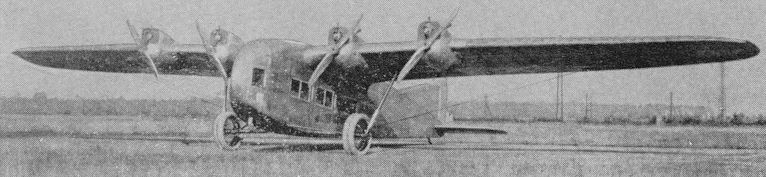
J.Herris - Zeppelin-Staaken Aircraft of WW1. Vol 2: R.VI R.30/16 - E.4/20 /Centennial Perspective/ (48)
More views of the Staaken E.4/20 on the field.
-

J.Herris - Zeppelin-Staaken Aircraft of WW1. Vol 2: R.VI R.30/16 - E.4/20 /Centennial Perspective/ (48)
The Staaken E.4/20 on the airfield. (PM Grosz Collection/STDB)
-

J.Herris - Weird Wings of WWI /Centennial Perspective/ (70)
The Zeppelin-Staaken company received all-metal technology from its Zeppelin-Lindau sister company and built the remarkable all-metal Staaken E.4/20 monoplane as a result. Built as a transport due to the armistice, it was faster than contemporary fighter planes such as the Spad 13. The E.4/20 was the world's first all-metal 4-engine cantilever monoplane and the ancestor of all modern 4-engine transports. (PM Grosz Collection/STDB)
-

J.Herris - Zeppelin-Staaken Aircraft of WW1. Vol 2: R.VI R.30/16 - E.4/20 /Centennial Perspective/ (48)
Staaken E.4/20 as built with original open cockpit. (PM Grosz Collection/STDB)
-

J.Herris - Weird Wings of WWI /Centennial Perspective/ (70)
The Staaken E.4/20 after the cockpit was converted from an open cockpit to a cabin. The two pilots sat side by side.The Inter-Allied Control Commission insisted the E.4/20 be destroyed and this historic aircraft had to be scrapped, not even surviving as a museum exhibit. (PM Grosz Collection/STDB)
-

J.Herris - Zeppelin-Staaken Aircraft of WW1. Vol 2: R.VI R.30/16 - E.4/20 /Centennial Perspective/ (48)
The Staaken E.4/20 after the cockpit was converted from the open cockpit to a cabin. (PM Grosz Collection/STDB)
-

J.Herris - Zeppelin-Staaken Aircraft of WW1. Vol 2: R.VI R.30/16 - E.4/20 /Centennial Perspective/ (48)
Side view of the Staaken E.4/20 before engines were installed. (PM Grosz Collection/STDB)
-

J.Herris - Zeppelin-Staaken Aircraft of WW1. Vol 2: R.VI R.30/16 - E.4/20 /Centennial Perspective/ (48)
Side view of the Staaken all-metal E.4/20.
-

J.Herris - Zeppelin-Staaken Aircraft of WW1. Vol 2: R.VI R.30/16 - E.4/20 /Centennial Perspective/ (48)
The Staaken E.4/20 in flight; taken from a magazine article.
-

J.Herris - Zeppelin-Staaken Aircraft of WW1. Vol 2: R.VI R.30/16 - E.4/20 /Centennial Perspective/ (48)
The Staaken E.4/20 in flight over the field. (PM Grosz Collection/STDB)
-

J.Herris - Zeppelin-Staaken Aircraft of WW1. Vol 2: R.VI R.30/16 - E.4/20 /Centennial Perspective/ (48)
Staaken E.4/20 in flight. (PM Grosz Collection/STDB)
-

J.Herris - Zeppelin-Staaken Aircraft of WW1. Vol 2: R.VI R.30/16 - E.4/20 /Centennial Perspective/ (48)
Closeup of the main landing gear of the Staaken all-metal E.4/20. The name 'Staaken' has been painted on the fuselage. (PM Grosz Collection/STDB)
-

J.Herris - Zeppelin-Staaken Aircraft of WW1. Vol 2: R.VI R.30/16 - E.4/20 /Centennial Perspective/ (48)
Passengers board the Staaken E.4/20. (PM Grosz Collection/STDB)
-

J.Herris - Zeppelin-Staaken Aircraft of WW1. Vol 2: R.VI R.30/16 - E.4/20 /Centennial Perspective/ (48)
Fore and aft views of the engine nacelles of the Staaken E.4/20 in the factory.
-

J.Herris - Zeppelin-Staaken Aircraft of WW1. Vol 2: R.VI R.30/16 - E.4/20 /Centennial Perspective/ (48)
Maybach Mb.lVa engine installation of the E.4/20 in the Berlin Technik Museum. (Michael Schmeelke)
-

J.Herris - Zeppelin-Staaken Aircraft of WW1. Vol 2: R.VI R.30/16 - E.4/20 /Centennial Perspective/ (48)
Another view of the all-metal Staaken E.4/20 under construction in the factory. (PM Grosz Collection/STDB)
-

J.Herris - Zeppelin-Staaken Aircraft of WW1. Vol 2: R.VI R.30/16 - E.4/20 /Centennial Perspective/ (48)
The Staaken all-metal E.4/20 under construction. (PM Grosz Collection/STDB)
-

J.Herris - Zeppelin-Staaken Aircraft of WW1. Vol 2: R.VI R.30/16 - E.4/20 /Centennial Perspective/ (48)
Original configuration of the pilot's cockpit in Staaken E.4/20 in the factory. (PM Grosz Collection/STDB)


-

J.Herris - Zeppelin-Staaken Aircraft of WW1. Vol 2: R.VI R.30/16 - E.4/20 /Centennial Perspective/ (48)
Another view of the Staaken E.4/20 in a soft spot in the field. (PM Grosz Collection/STDB)
-

J.Herris - Zeppelin-Staaken Aircraft of WW1. Vol 2: R.VI R.30/16 - E.4/20 /Centennial Perspective/ (48)
The Staaken E.4/20 in a soft spot on the field. (PM Grosz Collection/STDB)
-

J.Herris - Zeppelin-Staaken Aircraft of WW1. Vol 2: R.VI R.30/16 - E.4/20 /Centennial Perspective/ (48)
Ahead of its time: The Zeppelin-Staaken E4/20 metal aircraft designed by Adolf Rohrbach had to be scrapped in 1922. This was stipulated in the Treaty of Versailles.
On 21 November 1922 the Staaken E.4/20 was scrapped due to the demands of the IAACC. Note the cabin cockpit.


-

J.Herris - Zeppelin-Staaken Aircraft of WW1. Vol 2: R.VI R.30/16 - E.4/20 /Centennial Perspective/ (48)
Early in the construction process for the Staaken all-metal E.4/20. This appears to be a mock-up of the E.4/20 with wooden frame and canvas covering. (PM Grosz Collection/STDB)
-


-

J.Herris - Zeppelin-Staaken Aircraft of WW1. Vol 2: R.VI R.30/16 - E.4/20 /Centennial Perspective/ (48)
Staaken E.4/20 structural details showing the wing spar.
-

J.Herris - Zeppelin-Staaken Aircraft of WW1. Vol 2: R.VI R.30/16 - E.4/20 /Centennial Perspective/ (48)
Staaken E.4/20 structural details.
-

J.Herris - Zeppelin-Staaken Aircraft of WW1. Vol 2: R.VI R.30/16 - E.4/20 /Centennial Perspective/ (48)
Staaken E.4/20. Original configuration with open cockpit.
-

J.Herris - Zeppelin-Staaken Aircraft of WW1. Vol 2: R.VI R.30/16 - E.4/20 /Centennial Perspective/ (48)
Staaken E.4/20. Final configuration with enclosed cockpit.
-

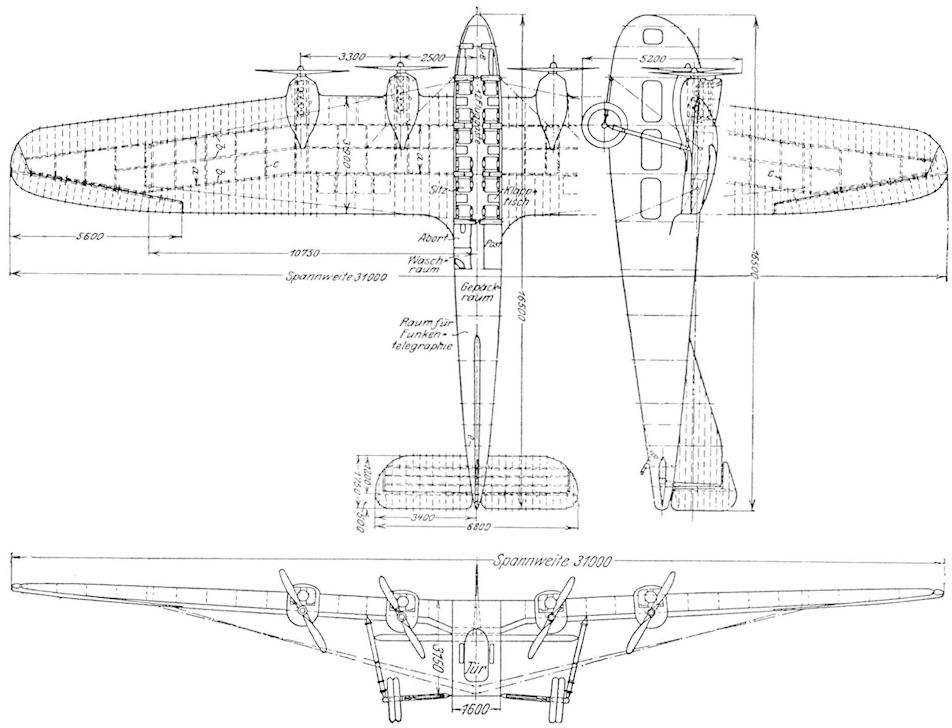
G.Haddow, P.Grosz - The German Giants /Putnam/
Factory drawing of the Staaken E.4/20 Civil airliner
-

-

-

-

J.Herris - Zeppelin-Staaken Aircraft of WW1. Vol 2: R.VI R.30/16 - E.4/20 /Centennial Perspective/ (48)
Staaken E.4/20. Final Configuration with Closed Cockpit.