
Книги
Putnam
O.Tapper
Armstrong Whitworth Aircraft since 1913
36
O.Tapper - Armstrong Whitworth Aircraft since 1913 /Putnam/
The first Armstrong Whitworth aeroplane to be designed by Koolhoven was a small single-seater. This aeroplane was known, probably correctly, as the F.K.I; the qualification arises because there is considerable uncertainty about the true sequence of the F.K. numbers. Koolhoven himself seems to have applied, in retrospect, F.K. numbers to all the designs with which he had been in any way concerned, and in one Dutch publication the F.K.I appears as the F.K.14. The uncertainty about the F.K. numbers is made worse by the secrecy concerning its experimental types which Armstrong Whitworth maintained even after the war.
The F.K.I, originally planned as a monoplane, was altered in the design stage to a biplane. It was a simple, straightforward, single-seat aircraft with single-bay wings, no stagger and a large gap. The fuselage terminated in a horizontal knife-edge, and there were divided elevators but no fixed tailplane. When first flown, by Koolhoven himself, the F.K.I proved to be seriously underpowered, having been fitted with a Gnome engine of 50 hp in place of the intended 80 hp version. Later, the aircraft was given larger ailerons and a fixed tailplane and in this form was flown by B. C. Hucks and some naval pilots; but there was clearly no future for the type and its development was abandoned.
The F.K.I, originally planned as a monoplane, was altered in the design stage to a biplane. It was a simple, straightforward, single-seat aircraft with single-bay wings, no stagger and a large gap. The fuselage terminated in a horizontal knife-edge, and there were divided elevators but no fixed tailplane. When first flown, by Koolhoven himself, the F.K.I proved to be seriously underpowered, having been fitted with a Gnome engine of 50 hp in place of the intended 80 hp version. Later, the aircraft was given larger ailerons and a fixed tailplane and in this form was flown by B. C. Hucks and some naval pilots; but there was clearly no future for the type and its development was abandoned.
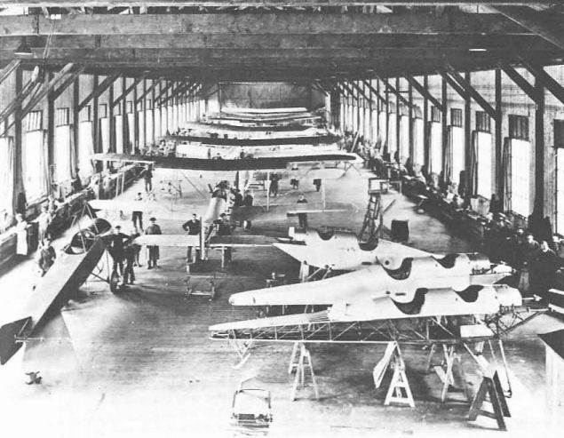
B.E.2c aircraft on the assembly line at Gosforth during the early months of 1915. On the left is the fuselage of the F.K.I single-seat biplane.
The Wartime Veterans
When Frederick Koolhoven joined Annstrong Whitworth in 1914 the works at Gosforth were being prepared for B.E.2c production and he concluded, after studying the official design, that it was unnecessarily difficult to build. He therefore straightway offered to design an aircraft which, without sacrifice of performance, would be easier to produce. Rather surprisingly, in view of their unshakable faith in the B.E.2c, the authorities agreed and, in August 1915, Koolhoven went ahead with the construction of the Armstrong Whitworth version, the F.K.3.
F.K.3
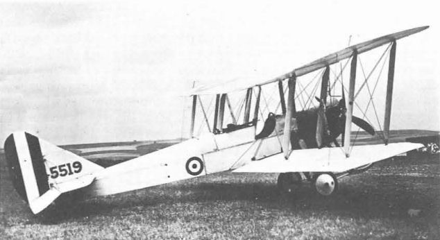
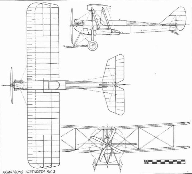
The F.K.3 bore an obvious resemblance to the B.E.2c, and it is evident that Koolhoven's ideas about improving the design were concerned mainly with the structural features; indeed, his aim was, among other things, to eliminate welding and intricate metal fittings. The F.K.3, like the B.E.2c, had a slender fuselage, high aspect ratio wings, and two-bay bracing; unlike the B.E, it had more dihedral on the top plane than on the bottom. The prototype, which was test-flown by Norman Spratt, was fitted with a 70 hp Renault engine, but production aircraft were powered by the RAF 1a of 90 hp. One F.K.3, No.5519, was tested in June 1916 with the more powerful RAF Ib engine, but the tests with this aircraft were plagued by constant engine failures due to faulty pistons.
Seating arrangements in the F.K.3 prototype followed the B.E.2c precedent of placing the observer in the front in a separate cockpit underneath the top wing, but this was later changed so that both crew members were accommodated in one large cockpit, with the observer at the back where he could use his Lewis gun with much greater effect. The rear portion of the long cockpit opening was shielded by side screens extending forward to the rearmost centre-section struts, giving from the side the appearance of two separate cockpits. All the earlier production aircraft with the observer's seat in front, of which there were twelve, were afterwards modified to reverse the crew positions. The undercarriage was of unusual design in that it employed oleo shock-absorbers mounted vertically on the sides of the fuselage from which struts extended down to the ends of a divided axle. A central skid extended forward from the axle to protect the propeller in the event of a tail-high landing.
No provision was made for a forward-firing gun, but the observer was provided with a Lewis gun mounted on a pillar behind his seat. As was the case with the B.E. aeroplanes, pilots used considerable ingenuity in attempts to equip themselves with some form of gun mounted to fire past the propeller, but none of the methods adopted was noticeably successful. External bomb racks fitted under the lower mainplane were capable of carrying bombs up to the weight of 112 lb but, because of weight limitations, it was usual to fly without the observer when bombs were carried.
An F.K.3, No.5552, with a 90 hp RAF la engine, was tested alongside a B.E.2c at the Central Flying School at Upavon in May 1916. The tests showed that the F.K.3 had a slightly better all-round performance and that it was lighter on the controls and more pleasant to handle. The report commented favourably on the crew positions, the roomy rear cockpit, and the ease of communication between the pilot and observer even without the use of a speaking tube; it criticized the positioning of control column and rudder bar and mentioned a draught in the cockpit coming from the fuselage openings at the junction of the undercarriage struts. In general the aircraft was considered to be well designed and easy to manufacture; it was simple to control and the oleo undercarriage was adjudged to be very good, although the long shock-absorber travel allowed the wingtips to touch the ground.
Early in the F.K.3 production run the RAF la engine became temporarily unobtainable and, at one time, according to a contemporary account, there were about a hundred complete aircraft awaiting engines. This may have been something of an exaggeration, but there is no doubt that a crisis had arisen and, in an endeavour to overcome it, some 120 hp Beardmore engines were sent to Newcastle in the hope that they might provide a satisfactory substitute.
The fitting of this engine into the F.K.3 presented many problems: the six-cylinder inline water-cooled Beardmore engine was some twenty inches longer than the RAF la and, even without the radiator, it was at least 90 lb heavier. To make room for the bigger engine, the fuel tank was removed from the fuselage and a larger, streamlined tank was located under the top centre section, together with a small header tank for the radiator. When installed, the engine sat high on its bearers and virtually blocked the forward view. The all-up weight of the aircraft was increased by about 400 lb, of which about 100 lb was accounted for by the additional fuel. To compensate for this extra load, the wing span of the aircraft was increased by two feet.
The first two Beardmore-powered F.K.3s (one of which was numbered 5528) were tested at Upavon in March 1916, and a report issued in May indicated that, although the climb performance was better than that of the RAF la version, the speed showed only a marginal improvement. That the Beardmore installation was not considered satisfactory is evident from the fact that all of the twelve aircraft so adapted were re-converted to standard as soon as RAF la engines again became available.
Precise production figures for the F.K.3 are difficult to ascertain because most of the official records of the time refer indiscriminately to Armstrong Whitworth biplanes without making any distinction between the F.K.3 and the F.K.8 which followed it. It is known that the War Office ordered one hundred and fifty F.K.3s from Armstrong Whitworth in 1915 and that the production rate is said to have reached 35 to 45 aircraft a month. In addition, orders for three hundred and fifty F.K.3s were placed with Hewlett & Blondeau of Luton, in Bedfordshire, a firm formed before the war by Gustav Blondeau, an early French aviator, and Mrs Maurice Hewlett, the wife of the author and herself the first British woman pilot.
In spite of the fact that the F.K.3 was clearly a better proposition than the B.E.2c, if only because it could defend itself more adequately if attacked from the rear, it seems that the type saw no active service on the Western Front, and the only operational unit that used it was No. 47 Squadron which served in Salonika from September 1916 until the end of the war. In that theatre the F.K.3s gave excellent service, performing a variety of duties including ground straffing, artillery spotting and bombing.
At home, the F.K.3 was used extensively for training, for which role its ease of handling and its ability to perform aerobatics made it eminently suitable, and it was probably the best of the British trainers until the arrival of the Avro 504. It was also used for observer training at the observer and air gunnery schools at Dymchurch, Hythe, Stirling and Turnberry. An F.K.3 was used as a personal transport by Major-General Sir Sefton Brancker, later to become the first Director General of Civil Aviation. He was a brave and resourceful man but a notoriously poor pilot, and his choice of the F.K.3 was a tribute to its ease of handling.
At the end of the war, in November J918, there were sixty-two F.K.3s still serving with the RAF, fifty-three at home, mostly based at flying schools, and nine in the Middle East. After the war only four found their way on to the civil register: G-EABY (ex B9629) and G-EABZ (ex B9518) which operated from Porthcawl, in South Wales, flown by E. D. C. Heme. Another, G-EAEU (ex B9612), was owned by the Kingsbury Aviation Co Ltd, but was crashed after a few months of civilian life. Finally, there was G-EALK (ex B9603) which was registered in the name of L. G. Lowe and held a certificate of airworthiness until September 1920.
A noticeable feature of the F.K.3 was an engine cowling panel carrying the initials 'AW'. These were not merely painted on but heavily embossed into the metal. As a result, perhaps not surprisingly, the aircraft soon became known, in the vernacular of the day, as the 'Ack·W' and, when its successor, the F.K.8, appeared with similar embellishment, it inevitably became another 'Ack-W': from then on the two aircraft were invariably referred to as the 'Little Ack' and the 'Big Ack'.
F.K.3
Dimensions: Span 40 ft (12.19 m); length 29 ft (8.84 m); height 11 ft 11 in (3.63 m); wing area 457 sq ft (42.46 sq m)
90hp RAF 1A 120 hp Beardmore
Max weight: 2,056 lb (933 kg) 2,447 lb (1,110 kg)
Empty weight: 1,386 lb (629 kg) 1,682 lb (763 kg)
Max speed
Sea level: 89 mph (143 km/hr) 91 mph (146 km/hr)
6,500 ft (1,981 m) 81 mph (130 km/hr) 84 mph (135 km/hr)
Stalling speed: 48 mph (77 km/hr) 56 mph (90 km/hr)
Climb
to 6,500 ft(1,981 m): 26.5 min 19 min
to 10,000 ft(3.048 m): 48.9 min 35 min
Service ceiling: 12,000 ft(3,658 m) 12,000 ft(3.658 m)
Endurance: 3 hr 3 hr
When Frederick Koolhoven joined Annstrong Whitworth in 1914 the works at Gosforth were being prepared for B.E.2c production and he concluded, after studying the official design, that it was unnecessarily difficult to build. He therefore straightway offered to design an aircraft which, without sacrifice of performance, would be easier to produce. Rather surprisingly, in view of their unshakable faith in the B.E.2c, the authorities agreed and, in August 1915, Koolhoven went ahead with the construction of the Armstrong Whitworth version, the F.K.3.
F.K.3
The F.K.3 bore an obvious resemblance to the B.E.2c, and it is evident that Koolhoven's ideas about improving the design were concerned mainly with the structural features; indeed, his aim was, among other things, to eliminate welding and intricate metal fittings. The F.K.3, like the B.E.2c, had a slender fuselage, high aspect ratio wings, and two-bay bracing; unlike the B.E, it had more dihedral on the top plane than on the bottom. The prototype, which was test-flown by Norman Spratt, was fitted with a 70 hp Renault engine, but production aircraft were powered by the RAF 1a of 90 hp. One F.K.3, No.5519, was tested in June 1916 with the more powerful RAF Ib engine, but the tests with this aircraft were plagued by constant engine failures due to faulty pistons.
Seating arrangements in the F.K.3 prototype followed the B.E.2c precedent of placing the observer in the front in a separate cockpit underneath the top wing, but this was later changed so that both crew members were accommodated in one large cockpit, with the observer at the back where he could use his Lewis gun with much greater effect. The rear portion of the long cockpit opening was shielded by side screens extending forward to the rearmost centre-section struts, giving from the side the appearance of two separate cockpits. All the earlier production aircraft with the observer's seat in front, of which there were twelve, were afterwards modified to reverse the crew positions. The undercarriage was of unusual design in that it employed oleo shock-absorbers mounted vertically on the sides of the fuselage from which struts extended down to the ends of a divided axle. A central skid extended forward from the axle to protect the propeller in the event of a tail-high landing.
No provision was made for a forward-firing gun, but the observer was provided with a Lewis gun mounted on a pillar behind his seat. As was the case with the B.E. aeroplanes, pilots used considerable ingenuity in attempts to equip themselves with some form of gun mounted to fire past the propeller, but none of the methods adopted was noticeably successful. External bomb racks fitted under the lower mainplane were capable of carrying bombs up to the weight of 112 lb but, because of weight limitations, it was usual to fly without the observer when bombs were carried.
An F.K.3, No.5552, with a 90 hp RAF la engine, was tested alongside a B.E.2c at the Central Flying School at Upavon in May 1916. The tests showed that the F.K.3 had a slightly better all-round performance and that it was lighter on the controls and more pleasant to handle. The report commented favourably on the crew positions, the roomy rear cockpit, and the ease of communication between the pilot and observer even without the use of a speaking tube; it criticized the positioning of control column and rudder bar and mentioned a draught in the cockpit coming from the fuselage openings at the junction of the undercarriage struts. In general the aircraft was considered to be well designed and easy to manufacture; it was simple to control and the oleo undercarriage was adjudged to be very good, although the long shock-absorber travel allowed the wingtips to touch the ground.
Early in the F.K.3 production run the RAF la engine became temporarily unobtainable and, at one time, according to a contemporary account, there were about a hundred complete aircraft awaiting engines. This may have been something of an exaggeration, but there is no doubt that a crisis had arisen and, in an endeavour to overcome it, some 120 hp Beardmore engines were sent to Newcastle in the hope that they might provide a satisfactory substitute.
The fitting of this engine into the F.K.3 presented many problems: the six-cylinder inline water-cooled Beardmore engine was some twenty inches longer than the RAF la and, even without the radiator, it was at least 90 lb heavier. To make room for the bigger engine, the fuel tank was removed from the fuselage and a larger, streamlined tank was located under the top centre section, together with a small header tank for the radiator. When installed, the engine sat high on its bearers and virtually blocked the forward view. The all-up weight of the aircraft was increased by about 400 lb, of which about 100 lb was accounted for by the additional fuel. To compensate for this extra load, the wing span of the aircraft was increased by two feet.
The first two Beardmore-powered F.K.3s (one of which was numbered 5528) were tested at Upavon in March 1916, and a report issued in May indicated that, although the climb performance was better than that of the RAF la version, the speed showed only a marginal improvement. That the Beardmore installation was not considered satisfactory is evident from the fact that all of the twelve aircraft so adapted were re-converted to standard as soon as RAF la engines again became available.
Precise production figures for the F.K.3 are difficult to ascertain because most of the official records of the time refer indiscriminately to Armstrong Whitworth biplanes without making any distinction between the F.K.3 and the F.K.8 which followed it. It is known that the War Office ordered one hundred and fifty F.K.3s from Armstrong Whitworth in 1915 and that the production rate is said to have reached 35 to 45 aircraft a month. In addition, orders for three hundred and fifty F.K.3s were placed with Hewlett & Blondeau of Luton, in Bedfordshire, a firm formed before the war by Gustav Blondeau, an early French aviator, and Mrs Maurice Hewlett, the wife of the author and herself the first British woman pilot.
In spite of the fact that the F.K.3 was clearly a better proposition than the B.E.2c, if only because it could defend itself more adequately if attacked from the rear, it seems that the type saw no active service on the Western Front, and the only operational unit that used it was No. 47 Squadron which served in Salonika from September 1916 until the end of the war. In that theatre the F.K.3s gave excellent service, performing a variety of duties including ground straffing, artillery spotting and bombing.
At home, the F.K.3 was used extensively for training, for which role its ease of handling and its ability to perform aerobatics made it eminently suitable, and it was probably the best of the British trainers until the arrival of the Avro 504. It was also used for observer training at the observer and air gunnery schools at Dymchurch, Hythe, Stirling and Turnberry. An F.K.3 was used as a personal transport by Major-General Sir Sefton Brancker, later to become the first Director General of Civil Aviation. He was a brave and resourceful man but a notoriously poor pilot, and his choice of the F.K.3 was a tribute to its ease of handling.
At the end of the war, in November J918, there were sixty-two F.K.3s still serving with the RAF, fifty-three at home, mostly based at flying schools, and nine in the Middle East. After the war only four found their way on to the civil register: G-EABY (ex B9629) and G-EABZ (ex B9518) which operated from Porthcawl, in South Wales, flown by E. D. C. Heme. Another, G-EAEU (ex B9612), was owned by the Kingsbury Aviation Co Ltd, but was crashed after a few months of civilian life. Finally, there was G-EALK (ex B9603) which was registered in the name of L. G. Lowe and held a certificate of airworthiness until September 1920.
A noticeable feature of the F.K.3 was an engine cowling panel carrying the initials 'AW'. These were not merely painted on but heavily embossed into the metal. As a result, perhaps not surprisingly, the aircraft soon became known, in the vernacular of the day, as the 'Ack·W' and, when its successor, the F.K.8, appeared with similar embellishment, it inevitably became another 'Ack-W': from then on the two aircraft were invariably referred to as the 'Little Ack' and the 'Big Ack'.
F.K.3
Dimensions: Span 40 ft (12.19 m); length 29 ft (8.84 m); height 11 ft 11 in (3.63 m); wing area 457 sq ft (42.46 sq m)
90hp RAF 1A 120 hp Beardmore
Max weight: 2,056 lb (933 kg) 2,447 lb (1,110 kg)
Empty weight: 1,386 lb (629 kg) 1,682 lb (763 kg)
Max speed
Sea level: 89 mph (143 km/hr) 91 mph (146 km/hr)
6,500 ft (1,981 m) 81 mph (130 km/hr) 84 mph (135 km/hr)
Stalling speed: 48 mph (77 km/hr) 56 mph (90 km/hr)
Climb
to 6,500 ft(1,981 m): 26.5 min 19 min
to 10,000 ft(3.048 m): 48.9 min 35 min
Service ceiling: 12,000 ft(3,658 m) 12,000 ft(3.658 m)
Endurance: 3 hr 3 hr
The crew positions were reversed in the second F.K.3 production batch so that the observer could use his gun to better effect.
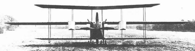
The standard F.K.3 was similar in appearance to the B.E.2c but had a rather better performance. This picture was taken at Doncaster in 1916.
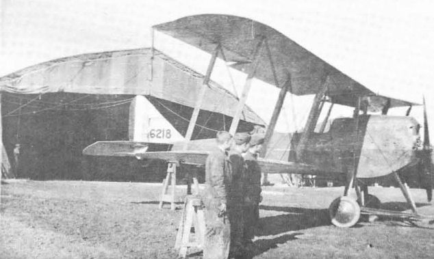
One of the first batch of fifty F.K.3s built by Hewlett and Blondeau Ltd.
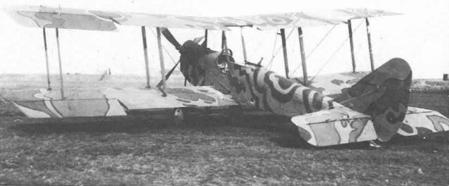
An F.K.3 with an interesting example of dazzle painting; or was it just a light-hearted decorative scheme?
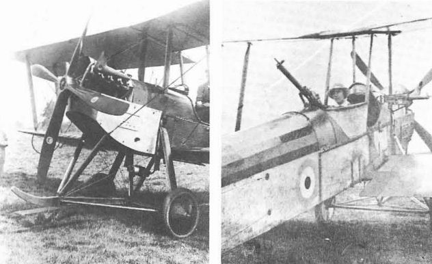
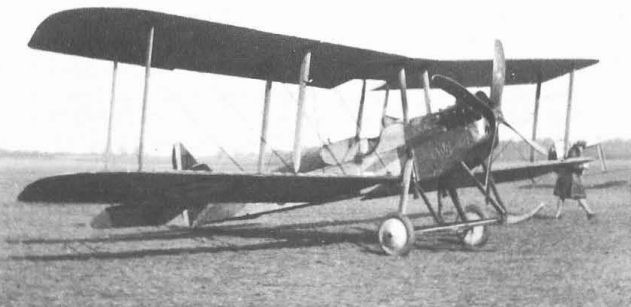
The F.K.3 was notable for its elaborate oleo undercarriage; on the right, an ingenious, but not altogether successful, attempt to provide a forward-firing gun.
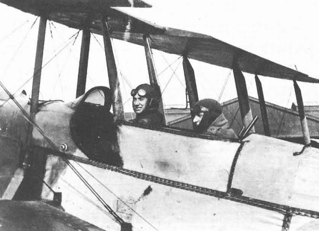
Instructor, in front, with a pupil in an F.K.3 training aircraft.
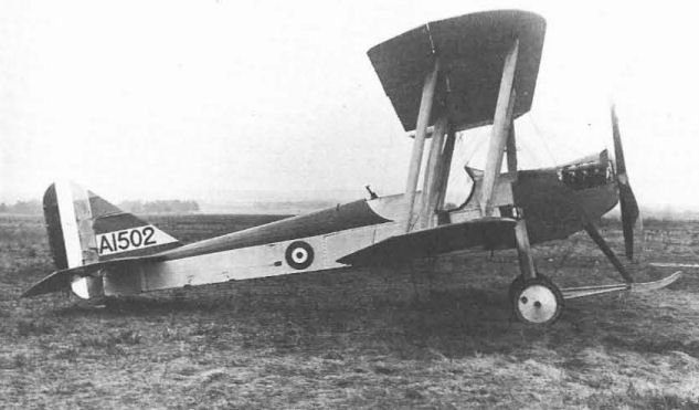
One of a small number of F.K.3 aircraft that were fitted temporarily with the 120 hp Beardmore engine.
The Koolhoven Multiplanes
In the early stages of the 1914--18 war, before the pattern of aerial warfare had developed, there was a school of thought in Great Britain which argued the merits of the 'flying battleship' or 'aerial destroyer'. This concept, which envisaged a large aeroplane with a multiplicity of guns having a wide field of fire, arose perhaps from the nation's deep-seated naval traditions. The proponents of the theory gave little regard to the virtues of speed or manoeuvrability, the idea apparently being that the aircraft would proceed in a dignified fashion, possibly in line ahead, firing broadsides at the enemy, who, it might be supposed, would adopt similar tactics. This may be extending the analogy too far, but the fact remains that considerable effort was expended in devising large fighter aeroplanes in which performance took second place to armament. Needless to say, the concept proved unsound, and it was the more adaptable fixed-gun fighter which dominated the scene where the battles were actually fought.
The large multi-seat-fighter notion certainly produced some odd-looking aircraft, with both Sopwith and Vickers trying their hand at the idea, but perhaps the strangest of all were the two Armstrong Whitworth triplanes produced to the designs of Frederick Koolhoven. The first of these featured two machine-gun nacelles mounted on the top surface of the middle wing, which was considerably longer than the other two. In order to provide the best possible field of fire for the two gunners, the nacelles projected well forward of the tractor propeller, which was situated but a few inches ahead of the wing leading edge. The pilot was placed behind the wings where his view in any direction, except upwards and backwards, must have been minimal. The engine was the new 250 hp Rolls-Royce twelve-cylinder unit which later became known as the Eagle. The undercarriage, which, like the rest of the aircraft, was highly unconventional, consisted of a single centrally placed shock-absorber strut terminating in two closely-spaced wheels, lateral stability being provided by a small single wheel under each wingtip. The tail was supported by a skid carried on long struts emanating from the underside of the fuselage at a point just aft of the wings. The whole aircraft seemed ill-balanced and gave the impression of frailty, and it is, perhaps, not surprising that Fairbairn-Crawford, the works manager, is on record as saying that he refused permission for it to be flown.
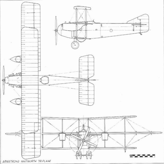
Subsequently, the design was re-vamped to conform to a requirement initiated by the War Office for a multi-seat escort fighter and Zeppelin destroyer. Using the same type of Rolls-Royce engine, the new triplane was larger than its predecessor and the span of all three wings was greater than before, with the overhang of the centre wing being less pronounced. A second bay was added to the wing structure, and the bracing appeared to be more substantial. The engine and propeller projected ahead of the wing in the conventional tractor position, and the pilot, again seated behind the wings, had a marginally better view but still not one calculated to arouse much enthusiasm. The undercarriage was short and carried a cross-axle with two pairs of wheels; the track was narrow and ground clearance for the lower wing was small. The two gun nacelles, this time attached to the underside of the middle wing, may have been designed to take the Davis gun. In April 1916 Armstrong Whitworth were supplied with two wooden mock-ups of the 6-pounder and the 2-pounder models for fitment to ‘... a large aeroplane now under construction for the War Office’, which can only have been the triplane. Four prototypes of the second triplane had been ordered in March 1916, but only No.7838 was built, it having by then become obvious that the large, ponderous fighting aeroplane was a mistake. Little is known about the test flights carried out by Peter Legh, but it seems they were somewhat perfunctory, with the performance failing to come up to expectations; in any case, interest in the project had already evaporated and the type was soon abandoned.
The place occupied by the triplanes in the F.K. series remains a mystery: both have been referred to as the F.K.12, but all the evidence points to the conclusion that this number is wrong. The comparative immaturity of the triplane designs would seem to indicate that they pre-dated the more workmanlike and more modem looking F.K.8 biplane and the subsequent quadruplanes which, for all their eccentricity, were more in accord with the designs of the later war years. More conclusive, perhaps, is the fact that both triplanes were designed before the adoption of the machine-gun interrupter gear, whereas the quadruplanes were clearly laid out with this type of armament in view. The true sequence of the F.K. numbers may never now be discovered, but the best guess is that the airship car, previously mentioned, which was an adaptation of the F.K.3 fuselage, was the F.K.4, with the two versions of the triplane following as the F.K.5 and the F.K.6.
In the early stages of the 1914--18 war, before the pattern of aerial warfare had developed, there was a school of thought in Great Britain which argued the merits of the 'flying battleship' or 'aerial destroyer'. This concept, which envisaged a large aeroplane with a multiplicity of guns having a wide field of fire, arose perhaps from the nation's deep-seated naval traditions. The proponents of the theory gave little regard to the virtues of speed or manoeuvrability, the idea apparently being that the aircraft would proceed in a dignified fashion, possibly in line ahead, firing broadsides at the enemy, who, it might be supposed, would adopt similar tactics. This may be extending the analogy too far, but the fact remains that considerable effort was expended in devising large fighter aeroplanes in which performance took second place to armament. Needless to say, the concept proved unsound, and it was the more adaptable fixed-gun fighter which dominated the scene where the battles were actually fought.
The large multi-seat-fighter notion certainly produced some odd-looking aircraft, with both Sopwith and Vickers trying their hand at the idea, but perhaps the strangest of all were the two Armstrong Whitworth triplanes produced to the designs of Frederick Koolhoven. The first of these featured two machine-gun nacelles mounted on the top surface of the middle wing, which was considerably longer than the other two. In order to provide the best possible field of fire for the two gunners, the nacelles projected well forward of the tractor propeller, which was situated but a few inches ahead of the wing leading edge. The pilot was placed behind the wings where his view in any direction, except upwards and backwards, must have been minimal. The engine was the new 250 hp Rolls-Royce twelve-cylinder unit which later became known as the Eagle. The undercarriage, which, like the rest of the aircraft, was highly unconventional, consisted of a single centrally placed shock-absorber strut terminating in two closely-spaced wheels, lateral stability being provided by a small single wheel under each wingtip. The tail was supported by a skid carried on long struts emanating from the underside of the fuselage at a point just aft of the wings. The whole aircraft seemed ill-balanced and gave the impression of frailty, and it is, perhaps, not surprising that Fairbairn-Crawford, the works manager, is on record as saying that he refused permission for it to be flown.
Subsequently, the design was re-vamped to conform to a requirement initiated by the War Office for a multi-seat escort fighter and Zeppelin destroyer. Using the same type of Rolls-Royce engine, the new triplane was larger than its predecessor and the span of all three wings was greater than before, with the overhang of the centre wing being less pronounced. A second bay was added to the wing structure, and the bracing appeared to be more substantial. The engine and propeller projected ahead of the wing in the conventional tractor position, and the pilot, again seated behind the wings, had a marginally better view but still not one calculated to arouse much enthusiasm. The undercarriage was short and carried a cross-axle with two pairs of wheels; the track was narrow and ground clearance for the lower wing was small. The two gun nacelles, this time attached to the underside of the middle wing, may have been designed to take the Davis gun. In April 1916 Armstrong Whitworth were supplied with two wooden mock-ups of the 6-pounder and the 2-pounder models for fitment to ‘... a large aeroplane now under construction for the War Office’, which can only have been the triplane. Four prototypes of the second triplane had been ordered in March 1916, but only No.7838 was built, it having by then become obvious that the large, ponderous fighting aeroplane was a mistake. Little is known about the test flights carried out by Peter Legh, but it seems they were somewhat perfunctory, with the performance failing to come up to expectations; in any case, interest in the project had already evaporated and the type was soon abandoned.
The place occupied by the triplanes in the F.K. series remains a mystery: both have been referred to as the F.K.12, but all the evidence points to the conclusion that this number is wrong. The comparative immaturity of the triplane designs would seem to indicate that they pre-dated the more workmanlike and more modem looking F.K.8 biplane and the subsequent quadruplanes which, for all their eccentricity, were more in accord with the designs of the later war years. More conclusive, perhaps, is the fact that both triplanes were designed before the adoption of the machine-gun interrupter gear, whereas the quadruplanes were clearly laid out with this type of armament in view. The true sequence of the F.K. numbers may never now be discovered, but the best guess is that the airship car, previously mentioned, which was an adaptation of the F.K.3 fuselage, was the F.K.4, with the two versions of the triplane following as the F.K.5 and the F.K.6.
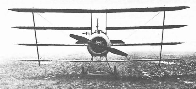
Another view of the one and only F.K.6 triplane No. 7838.
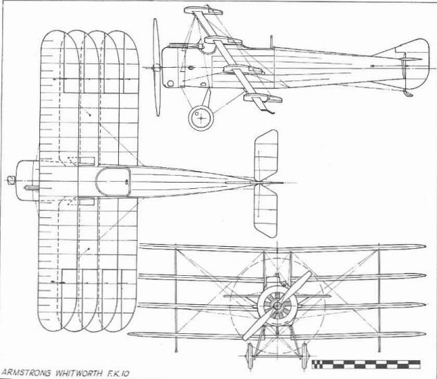
F.K.10
In spite of the disappointing performance of the first aircraft, a second, much modified, version was built. This was, indisputably, designated the F.K.10 and it had a more powerful Clerget engine rated at 130 hp. It had a similar wing arrangement but with the span increased by six inches, and, in order to give more room for the crew, the fuselage was both deeper and wider. The tail surfaces were also modified; instead of the fixed tailplane and no upper vertical fin, the second aeroplane had balanced elevators without fixed surfaces and vertical fins above and below the fuselage supporting a conventional, if rather small, rudder. In an attempt to overcome the undercarriage weakness of the previous aircraft, the longerons, from the undercarriage struts forward, were strengthened with plywood, but the structure was still not strong enough and it was reported that the diagonal struts within the fuselage, designed to take the compression loads from the undercarriage, were bent when the aircraft was delivered for official trials.
These trials were undertaken in March 1917, and the performance seems to have been slightly inferior to that of the lower-powered version. This may have been due to the fatter fuselage, but it is equally possible that the difference between the two aircraft arose because of variations in piloting skill and because of the somewhat imprecise methods of performance measurement then in use. The test pilot reported that the machine handled well, with good controllability and with very little tendency to spin. The take-off and landing distance was measured as 80 yards. As might be expected with an all-moving tailplane, the aircraft was somewhat unstable longitudinally, and the pilot noted that the controls could not, therefore, be left alone. In other respects the aircraft was considered easy to fly. Minor criticisms were that the windscreen was inefficient and that it was necessary to remove the engine cowling in order to replenish the oil tank. Like its predecessor, the second aircraft was reported as having a performance below that specified.
In view of the poor performance, an order for fifty F.K.10s which had been placed with Angus Sanderson and Co was cancelled in March 1917, and the serial numbers A8950 to A8999 set aside for this batch were reallocated. However, small batches of the F.K.10 were produced by Armstrong Whitworth, Angus Sanderson and the Phoenix Dynamo Manufacturing Co. Most of the production aircraft had the 130 hp Clerget engine, but at least one of those built by Armstrong Whitworth was powered by a Le Rhone engine of 110 hp. There is some uncertainty about the numbers of quadruplanes actually built: two, with the serial numbers A5212 and A5213, were ordered from Armstrong Whitworth, one of which may have been the original F.K.9, and a further five, numbered 83996 to 84000, were ordered from Angus Sanderson, but it is not known whether all were delivered. Three more, N511, N512 and N514, were built for the Royal Naval Air Service, the first two by Phoenix Dynamo and the third by Armstrong Whitworth. The missing number, N513, was originally allotted to an Angus Sanderson F.K.10 which was cancelled, and there is some evidence that this number was subsequently re-allocated to an Armstrong Whitworth biplane, presumably an F.K.8, with a Sunbeam engine: this aircraft is said to have force-landed near Beverley on 7 April, 1917, while en route from Newcastle to Martlesham Heath.
In spite of the official test reports, which indicated that the aircraft at least handled reasonably well, pilots seem to have been suspicious of the F.K.10 from the start. It certainly had a rather daunting appearance, and no doubt this, coupled with the maintenance problems, seems to have resulted in the few available aircraft being little used. The two RNAS machines, N511 and N514, were reported to be at Manston aerodrome in April and May 1917, but they were apparently considered to be unsafe and by the late summer had been grounded. The RFC aircraft may have lasted rather longer, but they, too, were never taken seriously and eventually, in July 1917, were handed over to the technical department for use as ground targets. Thus, the F.K.10 faded from the scene with, apparently, few regrets.
That Koolhoven's interest in the multiplane arrangement was not altogether damped by the failure of his three- and four-winged prodigies is evident from drawings that exist showing a design, known perhaps as the F.K.11, which had no less than fifteen narrow wings, each about 18-inches wide, attached to an F.K.10 fuselage. This project was never built, but the 'Venetian blind' arrangement of aerofoils had been tried before. One of the first to toy with the idea was Horatio Phillips, who tried out an apparatus with forty slats (if contemporary drawings are to be believed) on a circular track at Harrow in 1893. After the 1914--18 war the idea was revived by H. G. Leigh who, in collaboration with Bert Hinkler of the Avro company, fitted a modified form of the slatted-wing arrangement to the fuselage of an Avro Baby.
F.K.10
Dimensions: Span 28 ft 3 in (8.61 m); length 25 ft 6 in (7.77 m); height 11 ft 6 in (3.50 m); wing area 361 sq ft(33.54 sq m).
F.K.10
130 hp Clerget
Max weight: 2,019lb (916kg)
Empty weight: 1,236lb (561kg)
Max speed
Sea level: -
3,000ft (914 m): 95 mph (153km/hr)
6,500ft (1,981 m): 84 mph (135km/hr)
10,000 ft (3,048 m): 74 mph (119km/hr)
Climb to
6,000ft (1,829 m): -
6,500ft (1,981 m): 15.8min
10,000ft (3,048 m): 37.2min
Service ceiling: 10,000ft (3.048 m)
Endurance: 2 1/2 hr

Two F.K.10 quadruplanes and an F.K.8 biplane, with a Lorraine-Dietrich engine, at Duke's Meadow aerodrome at Gosforth.
Another view of the F.K.10 quadruplane.
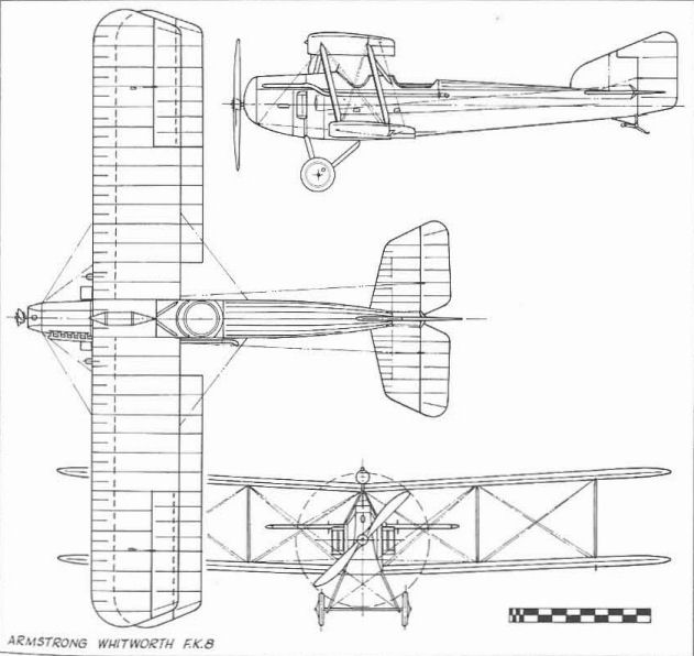
F.K.8
It was presumably a coincidence that two types of aircraft designed in 1916 for corps-reconnaissance duties should both bear the number 8 as their type designation; certainly, in all other respects they could not have been more dissimilar. The Armstrong Whitworth F.K.8 and the R.E.8, designed by the Royal Aircraft Factory, were both intended as B.E.2c replacements, and it was unfortunate for the long-suffering reconnaissance pilots of the RFC that it was the inferior R.E.8 that was chosen for massive production at the expense of the more popular F.K.8. Nevertheless, the F.K.8 was produced in considerable numbers and played a significant, if unspectacular, part in the war from the beginning of 1917 until the Armistice, including actions which led to the award of two Victoria Crosses.
Although designed for the same duties as its predecessor, the F.K.8 represented a considerable advance over the F.K. 3; it was planned from the start to accommodate internally all the various trappings of army cooperation, such as cameras, which, in previous types had been hung on outside with a noticeable effect on the aircraft's performance. The result, in the F.K.8, was a fuselage of ample proportions with comfortable separate cockpits for pilot and observer.
In construction the F.K.8 was a conventional biplane with two-bay wings of equal span and greater dihedral on the top plane than on the bottom. The upper wing was built in two portions which met on the centre line at the apex of two inverted-V centre-section struts. The controls were conventional; ailerons were fitted to all four wings and the incidence of the tailplane was adjustable by means of a handwheel in the pilot's cockpit. The observer was provided with a rudimentary method of control in the shape of a side-mounted stick to operate the elevators, and hand grips on the rudder control cables where they passed through the observer's cockpit. There was no means of operating the ailerons from this position but, as was shown several times in practice, it was quite possible to fly the aircraft satisfactorily without the aid of the ailerons and there were a number of occasions on which the aircraft was brought back safely by the observer after the pilot had been incapacitated.
The undercarriage was of similar design to that of the F.K.3, with oleo shock-absorbers mounted on the fuselage sides and with a central skid which, in the case of the F.K. 8, was truncated at the forward supporting struts. In April 1917 the RFC headquarters in France reported that the F.K.8's undercarriage was unsatisfactory and suggested that it should be replaced by a plain V-type specimen from a Bristol Fighter. This modification proved a big improvement and No.1 Aircraft Depot proceeded to convert a number of aircraft until, in the following July, the supply of Bristol Fighter undercarriages dried up and B.E.2c undercarriages had to be used instead. The gauge of tube used and the angle of the V was the same in both types, but the rear legs of the B.E. landing gear were shorter. This seems to have been of no great significance. Later, a modified type of undercarriage with a wider V appeared, and this may have been the production version fitted by the makers. The simpler type of landing gear improved the climb performance and raised the top speed by about 5 mph.
There is a widely-held opinion that the first production F.K.8s were powered by the 120 hp Beardmore engine, but in the light of recent research this belief is now thought to have been due to a misunderstanding. As already mentioned, both Armstrong Whitworth and the Service authorities were unusually lax in differentiating between the F.K.3 and the F.K.8, and this seems to have led to some confusion over the powerplants as well as over production figures. The mistake probably arose in the first place because the small batch of F.K. 3s fitted with the 120 hp Beardmore engine, as described earlier, were loosely referred to as 'Armstrong Whitworth 120 hp biplanes' and, because this variant was little known, it was naturally assumed that this description applied to the F.K.8. Apart from a statement in Jane's All the World's Aircraft for 1918 which was repeated in the following year and which may well have been the original source of the misunderstanding, there is a marked absence of direct evidence in favour of the 120 hp engine, and all the indications are that the F.K.8 was powered by the 160 hp Beardmore from the start.
During the course of production, other engines were tried out experimentally in the F.K.8. Two aircraft, B214 and B2l5, were fitted with variants of the twelve-cylinder air-cooled RAF 4 engine, the type which had, by its early unreliability, added to the unpopularity of the R.E.8. Another aircraft, A2696, was fitted with a Lorraine-Dietrich engine of 150 hp, but none of these engines bestowed any significant improvement on the F.K.8's performance and there was no move to adopt them as standard.
As first produced, the F.K.8 had a somewhat angular form of engine cowling, which gave the aircraft a vaguely Germanic appearance, and a crude form of radiator consisting of honeycomb blocks mounted on the sides of the fuselage and extending upwards and inwards to meet at a point in front of the top wing. This radiator proved to be inefficient in service and, as a result of a flood of complaints from the Western Front, a new type was adopted. This new radiator, which consisted of two elements mounted one each side of the fuselage, proved more effective as a radiator as well as improving the view from the cockpit. With the new compact type of radiator, a more rounded form of cowling was introduced, changes which resulted in a marked improvement in the appearance of the machine.
Another complaint voiced by Service pilots concerned the distortion of the view caused by the mirage effect of the fumes from the stub exhaust pipes. To overcome this, some enterprising officers of No. 10 Squadron in France devised and constructed a stack-type exhaust pipe which carried the fumes over the top wing. Permission was granted by RFC HQ in France for tests to be made with this exhaust system, but a warning was given that the large side area of the stack might affect the directional stability of the aircraft, and the advice was added that '... pilot ought to be warned not to do any short turns near the ground with it'. In fact, tests showed that there was no deterioration in directional stability, and the pilots of No. 10 Squadron were favourably impressed with the improvement in visibility and the fact that the after part of the aircraft was no longer smothered in oil: it was, however, noted that the design would have to be strengthened to withstand vibration. In the end this design was not adopted, but a modified system, consisting of a long exhaust pipe extending to a position aft of the observer's seat, was introduced.
The first flight of the F.K.8 took place in May 1916, and in the middle of the following month an F.K.8 numbered A411, which was almost certainly the prototype, was flown by a Service pilot from Newcastle to the Central Flying School at Upavon for official tests. The journey took two days, 16 and 17 June, and the pilot reported favourably on the aircraft's handling qualities. The tests by the CFS pilots were carried out on 18 and 19 June, and the top speed of the aircraft, the average of six runs over a measured course, was recorded as 98·4 mph. In the official report the F.K.8's performance was compared with that called for in the specification; it achieved 93 mph at 8,000 ft, as against the 100 mph called for, and it climbed to that height in 20 min, 4 min longer than the specified time. A criticism was made that the tailskid was not strong enough; later this fault was the cause of numerous complaints from the Western Front and, in 1917, the rudder shape was modified to avoid damage to its base when the skid broke. The test pilot also noted that when the aircraft was trimmed to fly level at 70 mph, it glided fast at 90 mph when the throttle was closed and that it would be an advantage if this tendency could be corrected. To this rather naive comment was added the remark that the aircraft would be good for reconnaissance but poor for bombing. Later, a cut-out between the spars at the root of the lower wing was provided to improve the pilot's view directly downwards. After tests at Upavon the F.K.8, A411, was returned to the makers for experimental work.
For reasons already stated when dealing with the F.K.3, production figures for the F.K. 8 are not now readily obtainable. The first production order for the F.K.8 was apparently that placed at the beginning of August 1916 with Armstrong Whitworth under contract 87/A/508, and such records as are available indicate that this, and two other contracts placed with Armstrong Whitworth, covered a total of 701 aircraft, not including the prototype. The F.K.8 was also built in large numbers by Angus Sanderson & Co, another Newcastle firm which had previously cooperated with Armstrong Whitworth by building bodies for their motorcars. Orders for some 950 F.K.8s were placed with this firm, which brings the total number of F.K.8s ordered to at least 1,652. By the end of 1917 between eighty and one hundred F.K.8s a month were coming off the Armstrong Whitworth line at Gosforth, and the type continued in production there until July 1918, by which time arrangements had been made for Angus Sanderson to continue with F.K.8 production while Armstrong Whitworth turned their attention to building the Bristol Fighter.
The first production F.K.8s were emerging from the Armstrong Whitworth factory at Gosforth at the end of 1916, and there are reports of individual aircraft being with the RFC in France before the year ended. However, the first squadron to be fully equipped with the type was No.35, which received its F.K.8s before proceeding to France in January 1917. Then came a gap until June, when No.2 Squadron, already in France, had its RE.s replaced by F.K.8s, which continued to be the squadron's equipment until the Armistice. Other squadrons in France which used the F.K.8 through to 1918 were Nos. 8, 10 and 82, while in the Near East the type, among others, was used by No.17 Squadron in Salonika and by No.142 in Palestine. The F.K.8 also formed part of the mixed equipment used in 1916 and 1917 for home defence by Nos. 36,47 and 50 Squadrons. It was an F.K.8 of No.50 Squadron, flown by 2nd Lieut F. A. D. Grace and 2nd Lieut G. Murray, that scored one of the few victories against a raiding Gotha, shot down in the North Sea on 7 July, 1917. The F.K.8 was also used quite extensively for training at home, particularly in the specialized arts of army co-operation, photography, map reading and reconnaissance.
In France the F.K.8 undertook a multitude of duties including night and day bombing, reconnaissance, artillery spotting, photography, trench straffing and even the dropping of supplies to forward troops. It was, like the RE.s before it, a maid of all work, but, unlike them, it was capable of putting up a fair degree of resistance when attacked, and had relatively good performance. The observer, with a Scarff mounting for his Lewis gun, had a good field of fire, while the pilot could operate a forward-firing, synchronized Vickers machine-gun. This defensive armament was used to good effect on 29 November, 1917, when Lieuts Pattern and Leicester, after a prolonged fight with five enemy fighters, succeeded in shooting down the German 'Ace' Erwin Bohme.
The battle-worthiness of the F.K.8 was demonstrated on two other occasions which, as already mentioned, resulted in the award of the Victoria Cross to two pilots. On 27 March, 1918, 2nd Lieut A. A. McLeod of No.2 Squadron with Lieut A. W. Hammond as his observer, flying in B5773, were attacked by eight Fokker Triplanes. In spite of being repeatedly wounded, between them the British pair accounted for four of the enemy before their aircraft, already severely damaged, caught fire. Lieut McLeod was forced by the flames to climb out of his cockpit but while standing on the wing managed to control the aircraft by manipulating the control column with one hand, side-slipping away from the flames and directing it towards the Allied lines; meanwhile Hammond, who had been wounded no less than six times, continued to hold the enemy at bay with his machine-gun. In spite of his wounds and the flames, McLeod Succeeded in bringing his aircraft to a comparatively soft crash landing in no-man's land from which both officers were rescued, still under heavy fire, by the infantry. The second F.K.8 pilot to be awarded the Victoria Cross was Captain (later Air Commodore) F. M. F. West of No.8 Squadron who, with his observer Lieut J. A. G. Haslam, was returning from a low-level bombing attack on German gun positions when his aircraft was attacked by six fighters. Although severely wounded in the legs, West managed to fly back to the Allied side of the lines and then refused to allow himself to be taken to hospital until he was able to pass on some important information about enemy troop concentrations.
The sturdy F.K.8 continued to serve on the Western Front until the war ended. At that time there were 182 of them in France, with 320 aircraft in reserve or under repair at home. Outside Europe there were fifty-six F.K.8s in Egypt and Palestine, forty-four in Salonika and two in the North West Province of India. In Great Britain there were sixty-nine aircraft on home airfields, mostly with training units.
After the war's end, the F.K.8 quickly faded from the scene in the RAF, and only eight found their way on to the British civil register; of these, three were sold abroad while the others were all crashed or otherwise written off before the end of 1920. The F.K.8's sole claim to fame in civil aviation is that of flying the first regular airmail service to be operated by a small Australian company, Queensland and Northern Territory Aerial Services Ltd, later to become better known as QANTAS. Formed in 1920 by two ex Australian Flying Corps pilots, W. Hudson Fysh and P. J. M. McGinnis, the company had been operating a successful hire service from their base at Longreach using a mixed fleet consisting of an Avro 504K with a Sunbeam Dyak engine, a D.H.4, an Avro Triplane, and two F.K.8s bearing the registrations G-AUCF and G-AUDE.
In 1922 the company was given a contract to operate a mail service between Charleville and Cloncurry with principal stops at Blackall, Longreach and Winton, railheads all connecting with the coast railway but not directly with each other. The route distance of 577 miles was scheduled to be flown in two days, with a night stop about half way at Longreach. The first service, which left Charieville at 5.30 a.m. on 2 November, 1922, was flown by McGinnis in the F.K.8 G-AUDE and carried a mail package containing 106 letters; it arrived at Longreach at 10.15 a.m., having averaged 82 mph excluding stops. The Longreach Cloncurry sector was scheduled to be flown on the following day by Hudson Fysh using the other F.K.8, G-AUCF, but, due to a slight drop in engine revolutions, this aircraft failed to take-off in the high temperature and G-AUDE was pressed into service again. This time the take-off was successful and the aircraft was soon on its way carrying the mail and one passenger, an 87-year-old settler named Alexander Kennedy.
The F.K.8s gave good service to QANTAS despite the fact that the rate of climb seldom exceeded 500 feet a minute and was often considerably less in the full heat of the day. At first some trouble was experienced with engines overheating, but this was cured by the fitting of larger radiators and a header tank which served to condense the steam if the radiator water did boil.
Thus, both in war and in peace, the F.K.8 carved for itself a positive niche in history for which it has received scant recognition, either in the annals of the time or since: perhaps it was its very qualities of stolid strength and reliability and its consistent but unspectacular performance which made everyone accept it and then forget about it.
F.K.8
Dimensions: Span 43 ft 6 in (13.26 m); length 31 ft 5 in (9.58 m); height 10 ft 11 in (3.33 m); wing area 540sq ft (50.17 sq m).
160 hp Beardmore 150 hp Lorraine Dietrich 150 hp RAF 4A
Max weight: 2,811 lb(1,275kg) 2,816 lb(1,277kg) 2,827 lb (1,282 kg)
Empty weight: 1,916 lb(869kg) 1,936 lb(878 kg) 1,980 lb (898kg)
Max speed
Sea level: 95 mph (153km/hr) - -
6,500 ft(1.981 m): - 89 mph (143 km/hr) 94mph(151 km/hr)
8.000 ft(2,438 m): 88 mph (142 km/hr) - -
10,000 ft(3,048 m): - 83 mph (134 km/hr) 89 mph (143 km/hr)
Climb to
6.500 ft(1.981 m): 15.4 min 16.5min 16.4min
8,000 ft(2,438 m): 20 min - -
10,000 ft(3.048 m): 27.8 min 33.2 min 32 min
Service ceiling: 13,000 ft. (3,962 m) 11,000 ft (3.353 m) 12,000 ft. (3.658 m)
Fuel capacity: 50 Imp gal (227 lt) 50 Imp gal (227 lt) 50 Imp gal (227 lt)
Endurance: 3 hr 4 hr 3 hr
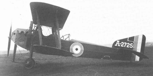
An early production Armstrong, Whitworth-built F.K.8, A2725, displaying the triple V-strut undercarriage, long vertical radiator blocks, angular nose cowling and short engine exhaust manifold.

An F.K.8 with the improved type of engine cowling, and, on the right, an experimental exhaust system devised by No.10 Squadron, RFC, in France to eliminate the distorting mirage effect from lhe open exhaust pipes.
Two F.K.I0 quadruplanes and an F.K.8 biplane, with a Lorraine-Dietrich engine, at Duke's Meadow aerodrome at Gosforth.
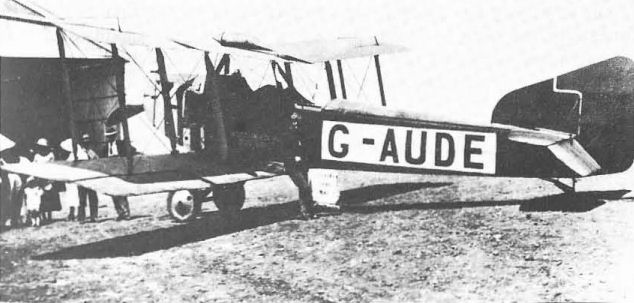
The F.K.8 used by Queensland and Northern Territory Aerial Services Ltd, later Qantas Empire Airways Ltd, to fiy Australia's first air mail service. The flight took place on 2 and 3 November, 1922, between Charleville and Cloncurry.

The F.K.8. G-AUDE. arrives with the mail at Winton on 3 November. 1922. The pilot was Wilmot Hudson Fysh, later Sir Wilmot. The date on the photograph is wrong.
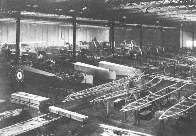
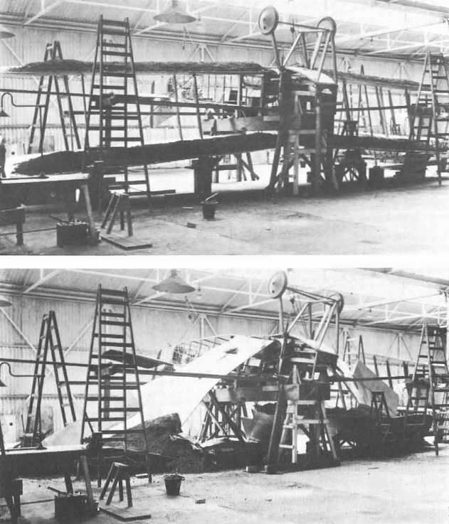
F.K.8 biplanes under construction in the Newcastle factory of Angus Sanderson and Co. The site is now occupied by Durham University.
The prototype F.K.8, A411, undergoes a test to destruction at the Royal Aircraft Factory, Farnborough. The load was applied with loose sand heaped on the underside of the mainplanes.
F.K.9
The quadruplane which followed the F.K.8 was built in two forms, a prototype, which underwent considerable modification, and a production version of which, however, only a handful were actually built. The production model was certainly designated the F.K.10, and it is more than likely that the earlier version was called the F.K.9, although this nomenclature lacks positive confirmation. The quadruplane, which was probably built as a private venture, was designed to meet a requirement referred to in an official report as 'Spec. No.2c', for a two-seater fighter. At the time of its design the Sopwith Triplane was enjoying a considerable success; with its excellent manoeuvrability and high rate of climb, it had established a formidable reputation as a fighter, especially among enemy pilots. The prowess credited to the Sopwith, and to its equally successful antagonist, the Fokker Triplane, resulted in the production of a crop of triplanes, both friend and foe, most of which were, incidentally, without distinction. Koolhoven, perhaps, hoped to go one better on the principle that you cannot have too much of a good thing, and his new aircraft materialized with four heavily-staggered wings ranging from well below the fuselage to high above the pilot's head. The fuselage was comparatively slender, with pilot's seat situated immediately behind the rotary engine, from where his view, except rearwards and upwards, was virtually unobstructed. The observer's cockpit was placed immediately behind the third wing from the bottom, which itself was positioned just above the fuselage. This wing had no centre section and the leading edges protruded forward on either side of, and slightly above, the pilot's head. The wing structure was supported by plank-type centre-section and interplane struts with wire bracing, while the tailplane was adjustable and carried unbalanced elevators. There was a small fixed fin below the fuselage but none above, and the rudder was balanced. The undercarriage looked rather frail and consisted of two single wire-braced struts with a cross-axle and rubber-cord shock-absorbers. The wings of the F.K.9, as it first emerged, had no dihedral and the ailerons were set well in from the tapered wingtips. After flight trials the aircraft was modified with new wings whose ailerons extended to the wingtips and were rounded with no taper.
The modified quadruplane, powered by a 110 hp Clerget engine, was tested at Upavon aerodrome, then the home of the Central Flying School, and was reported as being light to handle and easy to manoeuvre, but with a cockpit so cramped that the full movement of the control column, particularly from side to side, was not possible; in addition, the wheel for adjusting the tailplane trim was said to be inaccessible. The stability of the aircraft in all three senses was stated to be good, but the pilot complained of being smothered with oil and, not unnaturally, suggested that the cowling should be redesigned. During the trials it was found necessary to true-up the fuselage and undercarriage after every landing, however gentle, because of, in the words of the report, '... the absence of forward undercarriage struts ... so that on landing the full weight comes on the two side bracing wires of the nacelle'. The test figures showed that the top speed at ground level was just short of 100 mph, and that at 6,700 ft it had fallen off to 94 mph. It took 12 1/2 min to climb to 6,000 ft and the ceiling was about 13,000 ft, while the endurance was quoted as barely three hours. The report concluded that the performance was far below that called for in the specification.
F.K.9
Dimensions: Span 27 ft 9 in (8.46 m); length 25 ft 10 in (7.87 m); height 11 ft 4 in (3.45 m); wing area 355 sq ft(32. 98 sq m).
F.K.9
110 hp Clerget
Max weight: 2,038lb (924 kg)
Empty weight: 1,226lb (556 kg)
Max speed
Sea level: 100mph (161km/hr)
3,000ft (914 m): -
6,500ft (1,981 m): 94mph (151 km/hr)
10,000 ft (3,048 m): 87mph (140 km/hr)
Climb to
6,000ft (1,829 m): 12.5min
6,500ft (1,981 m): -
10,000ft (3,048 m): 25 min
Service ceiling: 13,000 ft (3.962 m)
Endurance: 3hr
F.M.4 Armadillo
After Koolhoven left Armstrong Whitworth in 1917 to go to the British Aerial Transport Co, the design duties at Gosforth were undertaken by Frank Murphy, who had been the manager of the aeroplane department under Fairbairn-Crawford. The first aircraft to be built to Murphy's design was the F.M.4, the Armadillo, a single-seat fighter, powered by a Bentley B.R.2 rotary engine and fashioned to meet the requirements of the Air Board specification A1(a). The Armadillo was not ordered by the Government although in January 1918 the Air Board gave Armstrong Whitworth a licence '... to build two machines at their own risk and expense'. This was done because Armstrong Whitworth had expressed a wish to check the capabilities of the design staff with a view to taking up original design work once more. Thus, although the F.M.4 was nominally a contender for the fighter contract, it was, in fact, never seriously considered for this either by the company or by the Air Board. Indeed, officials of the Board were less than enthusiastic about the F.M.4, and an internal memorandum dated 26 February, 1918, stated that '... this machine is hardly likely to come into competition with other B.R.2 scouts'. In the event, the Sopwith Snipe had been ordered into production by the time the Armadillo appeared.
Although the licence specified two aircraft, only one, X19, was completed: the second aircraft, X20, being abandoned after it had reached a fairly advanced stage of construction. The first aircraft was designed to have three sets of interchangeable wings, two of which were designated 'AW No.1 Camber' and 'AW No.2 Camber', while the third set was of RAF 14 section and was of reduced span with a shorter overhang at the tips. The second F.M.4, besides other minor alterations, was to have had two sets of wings of RAF 14 and RAF 15 section. In appearance the Armadillo was a squat, two-bay biplane with a fuselage filling the rather narrow gap. The wings were of equal span, but the bottom wing, which alone had a slight dihedral angle, was narrower than the top. The 230 hp B.R.2 rotary engine was housed in a bulbous cowling set low on the fuselage with a top fairing housing two Vickers synchronized machine-guns. This also served to fair off the joint between the low-set cowling and the top line of the fuselage. Provision was also made for a hand-operated Lewis gun which could be elevated to fire forwards and upwards over the propeller. The pilot was seated just ahead of the trailing edge of the wing with his eyes slightly above the level of the wing; both upper and lower wings had a trailing-edge cut-out to improve the downward view. For the same reason the sides of the cockpit were also cut away quite deeply on either side, and this led to a discontinuity in the top longerons; to compensate for this the sides of the fuselage around the cockpit were covered with three-ply wood. For additional strength, the forward portion of the fuselage was reinforced with two channel-section duralumin girders which also supported the fuel tanks and the pilot's seat. The V-struts of the Armadillo's undercarriage were of rather light section and were later replaced by somewhat stronger members.
The design of the F.M.4 was completed in the autumn of 1917, and an officer from the Air Board inspected the mock-up in December 1917. At that time the bottom wing was carried on struts some ten inches below the bottom longerons. The inspector suggested that the fuselage should be made deeper to fill the gap between the wings; he also suggested a rearrangement of the guns, moving the Lewis gun from the centreline so as not to interfere with the fitting of a windscreen and a gun sight. The licence for the two aircraft was issued on 7 January, 1918, and construction of the first aircraft went ahead quickly; by the middle of the month Armstrong Whitworth were pressing the Board for an early delivery of the B.R.2 engine.
During January 1918 the airframe of X 19 was inspected by Commander Ogilvie of the Air Board and sometime in February he criticized the structural design, stating that in his opinion'... the machine is somewhat weak all over'. He added that the compression ribs were weak, the attachment of the tailplane front spar was unsatisfactory and the spindling of the wing spars had been continued too far towards the points of support. Correspondence on these matters went to and fro between the Air Board and the company during February and March 1918 (one letter from the Board referred to the aircraft as the 'armoured Dillo') until, at the beginning of March, the company wrote stating that the spars and internal bracing of the mainplanes had been strengthened, the bracing of the fuselage modified and the interplane struts and front outer lift wires increased in section. Other modifications included an alteration to the tailplane bracing and the fitting of a stronger main tube in the rudder.
Following these modifications and a further inspection by Ogilvie, Armstrong Whitworth were informed towards the end of March 1918, that the aircraft was now up to strength everywhere and that it was passed for experimental flying. Whether the previous criticisms were in fact justified will never be known, but the fact remains that from a structural point of view the Armadillo seems to have had some merit. This is evident from the fact that in April the Air Ministry's stress expert, Professor A. J. Sutton Pippard, noted that the structure weight of the aircraft, which worked out at 26 per cent of the total, was unusually low. Following this assessment, Armstrong Whitworth were asked to supply a detailed breakdown of the Armadillo's weight. This analysis, arrived at by weighing each component, gave a weight of 1,730 lb; after a further study of the design, Pippard stated that he could find no trace of weakness in the structure and suggested that the low weight could he due to the small gap, the light interplane struts and the absence of a centre section.
As was so often the case with new aircraft at this time, the first flight was delayed pending delivery of an engine; this was eventually received in March 1918 and on the 18th of the month Armstrong Whitworth wrote to the Air Ministry announcing the arrival of the engine and seeking permission to use Cramlington aerodrome for the Armadillo's first flight, stating that the Town Moor field was not suitable because of the surrounding obstructions and the rough surface. The company added that they had engaged a well-known test pilot to carry out the initial tests before the machine was handed over to the Air Ministry; this was probably Clifford Prodger, who did some further testing of the Armadillo at a later date. Permission to use Cramlington (then controlled by Headquarters, Training Division, RFC) was granted, and on 3 April Armstrong Whitworth telegraphed the Air Ministry reporting that the Armadillo would fly on the following Saturday, 6 April. Whether it did so or not is uncertain, but it undoubtedly flew before 1 May, on which day, a report states, '... it flew again'. On Wednesday, 8 May, the aircraft was tried out by an RAF pilot who reported back to the Air Ministry that he found it most unsatisfactory. According to this pilot the Armadillo was very tail heavy and flew left wing low at full power; the aileron control was very heavy and it was difficult to move the stick laterally at high speed. He also complained that the control column was placed too far forward and that it fouled the instrument panel if the hand was placed on top of the stick. Another criticism was that the tailskid was too short so that the rudder was damaged during taxiing. All these faults could no doubt have been put right relatively easily: more serious was the fact that the pilot's view when landing was very bad, a defect that would have been difficult to rectify without considerable redesign. As a result of this report, the Assistant Controller, Design, at the Air Ministry wrote to the company on 18 May, 1918, saying that in view of the bad outlook from the cockpit during landing, the aircraft would not he sent to Martlesham and it would not be flown again by Service pilots. The Ministry's concern for the well-being of the RAF test pilots did not, apparently, extend to their civilian counterparts, for the letter went on to suggest that Armstrong Whitworth should conduct their own trials so as to obtain as much data as possible.
After some further modification, which included the fitting of the more robust undercarriage, Clifford Prodger made some tests on 7 June, 1918, and the figures that he recorded, although almost certainly optimistic, seemed to indicate that the aircraft had quite a respectable performance. The climb to 10,000 ft was said to have been accomplished in about 6 1/2 min and the speed at that height was given as 112 mph; at an altitude of 4,000 ft the aircraft reached 120 mph with the engine turning over at 1,300 rpm. There is little on record regarding subsequent activities: the company stated its intention of trying out different propellers, one with four blades and another with a finer pitch but, in view of the discouraging attitude of the Air Ministry, no further serious development work was undertaken, Murphy having already turned his attention to the Armadillo's successor.
F.M.4 Armadillo
Dimensions: Span 27 ft 9 in (8.46 m); length 18 ft 10 in (5.74 m); height 8 ft 7 in (2.62 m); Wing area 232 sq ft (21.56 sq m).
F.M.4 Armadillo
130 hp Bentley B.R.1
Max weight: 1,860 lb (844 kg)
Empty weight: 1,250 lb (557kg)
Max speed
Sea level: 125 mph (201 km/hr)
10,000 ft (3,048 m): 112 mph (182 km/hr)
Climb
to 10,000ft (3,048m) 6.5 min
Service ceiling: 24,000 ft (7,315 m)
Endurance: 2 3/4 hr
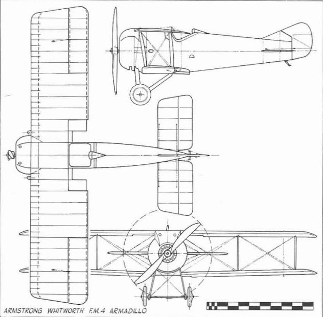
Ara
In 1917 a new engine had emerged which promised to give decisive air superiority to future British fighters: this was the A.B.C. Dragonfly radial engine which was supposed to give 320 hp for a weight of only 600 lb. Murphy, like many other designers, was quick to appreciate what might he accomplished with a powerplant of this calibre, and early in April 1918 Armstrong Whitworth asked the Air Ministry for blue prints of the Dragonfly; in reply, the Assistant Controller, Design, suggested that the company should not embark on a new design until the Armadillo had been tested, and that it would be advisable to have discussions with the Assistant Controller about which type of aircraft should next he undertaken. But Armstrong Whitworth had their own ideas on the subject and, in spite of the official advice, Murphy went ahead with the design of a Dragonfly-engined fighter. At some stage in the proceedings the official policy must have changed, for three examples of the new fighter, later to he named the Ara, were ordered. The Ara should logically have borne an F.M. number, presumably F.M.5, but it never seems to have carried this designation.
This second Armstrong Whitworth single-seat fighter retained the two-bay type of wing structure and the same type of slab-sided fuselage which characterized the Armadillo, but this time the top wing was raised a short distance above the fuselage, although the gap was still somewhat narrow. The wings were of equal span, but the chord of the lower wing was less than that of the top wing. The tailplane was conventional, with the fin and rudder, like those of the Armadillo, rather on the small side. The Dragonfly engine was neatly installed in a cowling that faired smoothly into a pointed spinner on the propeller boss. Comparative figures, if they are to be believed, show that the Ara, like the Armadillo, had an unusually low structure weight; both aircraft were of roughly the same size, but the Dragonfly engine weighed some 150 lb more than the B.R.2 rotary; nevertheless, the Ara was only about 70 lb heavier than the Armadillo and both had approximately the same useful load.
Like its numerous contemporaries, the Ara had no chance of survival because the Dragonfly engine failed completely to fulfil its initial promise. It had been designed by Granville Bradshaw whose object was to produce a light, high-powered radial which would be easy to build on a large scale. Unfortunately, the authorities were too easily persuaded by Bradshaw's optimism, and the engine was put into production before adequate testing had taken place. In the event, the Dragonfly, on which the nation's biggest production effort was to be concentrated, not only failed to develop the power expected, but suffered, among other troubles, from a species of high-frequency vibration which led to the wrecking of the engine after a few hours' running. At that time there was no known cure for this trouble and the whole engine production programme had eventually to be abandoned. Fortunately the war ended before the full impact of this debacle could have its effect.
The first Ara, F4971, was completed during the summer of 1918, but no engine was immediately available. By the time the first engine was delivered to Armstrong Whitworth in December, it had already been decided that the Ara would not be put into production; the war was over, and by now the Dragonfly's troubles were beginning to become apparent. Nevertheless, two of the three aircraft ordered were completed, the second aircraft, F4972, having a larger gap with the lower wing running below the fuselage. Work on the third airframe was discontinued at a late stage of construction. Because of engine unreliability, no systematic trials were carried out with the Ara, but such figures as are available indicate that, when the engine worked, the aircraft had a good performance, with a top speed of about 150 mph at sea level, and the ability to climb to 10,000 ft in 4 1/2 min. The ultimate fate of the two aircraft is not known, but doubtless they soon found their way on to the scrap heap. The Ara was the last of the Armstrong Whitworth designs to be built at Gosforth and, as recorded elsewhere, the company's aeroplane department was closed down at the end of 1919.
Ara
Dimensions: Span 27 ft 5 in (8.36 m); length 20 ft 3 in (6.17 m); height 7 ft 10 in (2.39 m); wing area 257 sq ft (23.88 sq m).
Ara
320 hp A.B.C. Dragonfly
Max weight: 1,930 lb (875 kg)
Empty weight: 1,320 Ib (599 kg)
Max speed
Sea level: 150 mph (241 km/hr)
10,000 ft (3,048 m): 145 mph (233 km/hr)
Climb
to 10,000ft (3,048m) 4.5 min
Service ceiling: 28,000 ft (8,534 m)
Endurance: 3 1/2 hr
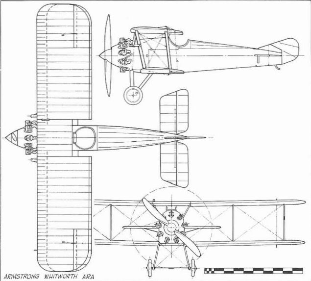
The Siskins
The most significant aircraft to be designed and built by the Siddeley Deasy company was the S.R.2, a single-seat fighter which, in its developed form, was to become famous in the RAF. Originally it had been intended that the S.R.2 should be powered by the proposed 300 hp fourteen-cylinder two-row radial engine which, as the RAF 8, was being designed under Major Green at Farnborough but was passed over to Siddeley Deasy when Green joined the company in 1917. In the event, the development of the radial engine was deferred so that priority could be given to bringing the Puma engine up to production standard. Thus it was that the Siddeley S.R.2, afterwards to be named the Siskin, was first flown with the ill-fated A.B.C. Dragonfly nine-cylinder radial engine.
It was natural that a fighter designed by John Lloyd under the direction of Green should bear a resemblance to the S.E. series built under Green's leadership at Farnborough and, in fact, the Siskin's S.E. parentage was clearly evident. It has been suggested that the design which emerged as the Siskin had already been roughed out by Green before he left Farnborough, but both he and Lloyd have denied that this was so: nevertheless, it seems likely that, but for the change in Government policy towards Farnborough, the aeroplane that became the Siskin might very well have been the S.E.7.
Whatever may be the truth of its origin, the Siskin was a very good aeroplane and, together with the engine which later became the Jaguar, it was responsible for the initial success of the Armstrong Whitworth company - although it was still some way into the future when the first Siskin made its maiden flight from Coventry's Radford aerodrome in the spring of 1919. It was an elegant biplane with wings of unequal span and chord and a spidery-looking undercarriage with long-stroke oleo shock-absorbers, a feature that became familiar on all subsequent Siskin variants. The Dragonfly engine was neatly installed in a well-streamlined cowling with individual cooling channels for each cylinder and blending into a spinner on the propeller boss.
On test in the summer of 1919, the Siskin was found to have excellent handling and stability characteristics. Its performance, too, was generally superior to most of its Dragonfly-powered contemporaries. An Air Ministry test report records that the S.R.2 attained a speed of 145 mph at 6,500 ft and climbed to 10,000 ft in just under eight minutes.
The original order for the Siddeley Deasy fighter was placed sometime early in 1918 and was for six aircraft, but later in the year the order was cut to three, by which time the first of the S.R.2 airframes was partially completed. By this time, too, it had become clear that the 300 hp radial would not be forthcoming in time and, as explained above, it was decided to substitute the A.B.C. Dragonfly engine. Even then, a shortage of Dragonfly engines held up the completion of the three aircraft-which bore the serial numbers C4541, C4542 and C4543 - and although the first airframe was probably completed some time in the latter half of 1918, the first flight does not appear to have taken place until early in 1919. With the failure of the Dragonfly engine in 1919, the Siskin passed into eclipse and, apart from a brief appearance at the RAF Pageant at Hendon in June 1920, little was heard of it until C4541 reappeared in March 1921, now fitted with the new Armstrong Siddeley Jaguar radial engine and bearing the family name of Armstrong Whitworth in place of Siddeley Deasy.
<...>
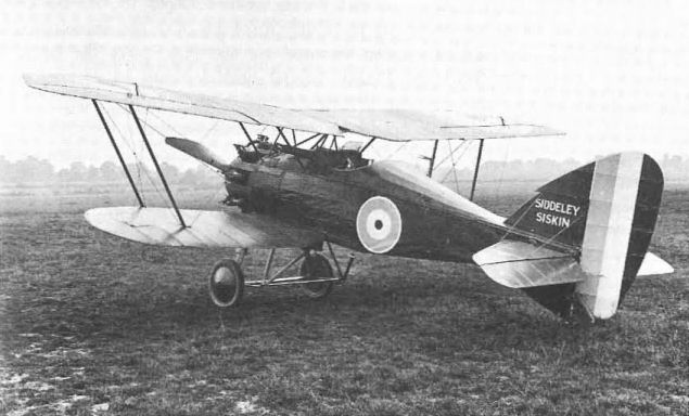
The first Siskin, the S.R.2, designed by Lloyd and built in 1918 by the Siddeley Deasy company. The engine was a 320 hp A.B.C. Dragonfly.
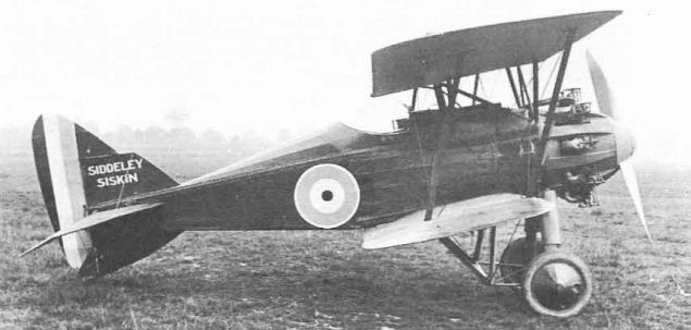
The Siddeley Siskin S.R.2 fighter completed in Coventry in 1919.

The Siskin was considered to be among the best of the fighters fitted with the A.B.C. Dragonfly engine.
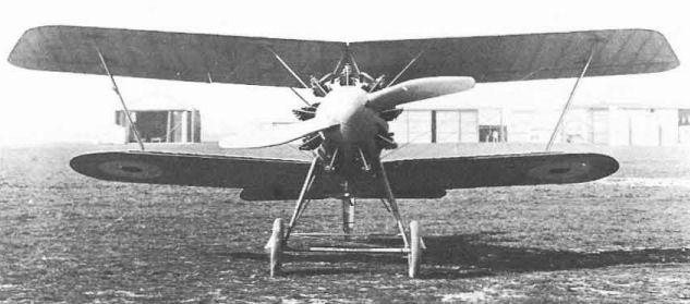
The unusual undercarriage design of the S.R.2 was to be a characteristic feature of all subsequent Siskin variants.
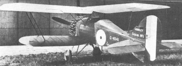
In 1921 the S.R.2, C4541, now known as the Armstrong Whitworth Siskin, reappeared with an early example of the Jaguar engine.
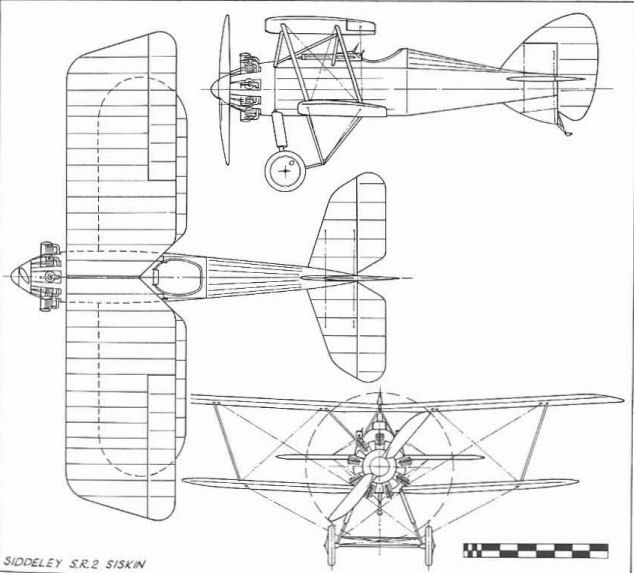
Siddeley S.R.2 Siskin
The Bristol F2B Fighter
By the year 1918, the F.K.8, which had been Armstrong Whitworth's main preoccupation in Newcastle since the autumn of 1916, was becoming obsolete and, in the spring of that year, production of this aircraft ceased and its place was taken by the Bristol Fighter, 250 of which had been ordered in February 1918.
The Bristol F2B Fighter, first produced in the autumn of 1916, was one of the outstanding aircraft of the First World War. Designed as a fighter-reconnaissance aircraft, the Bristol Fighter, with its high performance, combined the best characteristics of the fast, manoeuvrable, single-seat fighter with the fire power of the two-seater, and it proved itself to be a formidable opponent in the battles on the Western Front from the middle of 1917 onwards.
The engine of the standard Bristol Fighter was the Rolls-Royce Falcon, but production of this engine could not keep pace with the demand, and other powerplants had, perforce, to be used, with some inevitable loss of performance. One of the alternative engines was the 200 hp eight-cylinder water-cooled Sunbeam Arab, and it was this version that was ordered from Armstrong Whitworth. But the Arab engine was, itself, a disappointment: it suffered from severe vibration problems and, at some stage during the production run at Gosforth, the Siddeley Puma engine was substituted. This change-over probably occurred after the Armistice, by which time some sixty per cent of the order had been completed. The Bristol Fighter continued in production at Gosforth after the end of the war, but it cannot be confirmed whether or not all the 250 aircraft ordered, which were allotted the serial numbers E1901 to E2150, had been completed when, according to the company records, the contract was cancelled in September 1919.
Span: 39 ft 3 in (11.96 m)
Length: 24 ft 10 in (7.57 m)
Height: 9 ft 5 in (2.87 m)
Wing area: 405.6 sq ft (37.63 sq m)
All-up weight: 2.800 lb (1.270 kg)
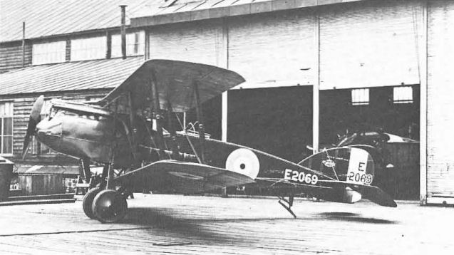
F.2B built by Armstrong Whitworth and fitted with Puma at Elswick Works, Newcastle-on-Tyne, in 1918. In 1918 the Bristol Fighter took the place of the F.K.8 in the Gosforth factory.
The B.E.2a, B.E.2b and B.E.2c
The first aeroplanes to be built by Armstrong Whitworth for the Government were eight B.E.2as which had been ordered in 1913. The B.E. series originated at the Army Aircraft Factory at Farnborough (renamed the Royal Aircraft Factory in 1912) and the first aircraft of the type, the B.E.1 which appeared in 1911, was the result of collaboration between two of the Farnborough designers, F. M. Green and Geoffrey de Havilland. The B.E.1 was very advanced for its time, both structurally and aerodynamically, and it did much to establish the fashion for the tractor biplane which was to persist for so many years.
The B.E.2a, powered by a 70 hp air-cooled Renault engine, appeared towards the end of 1912 and was basically similar to the preceding B.E.1 and B.E.2 aircraft. The structure was of wood, fabric covered, with unstaggered two-bay biplane wings. The tailplane was semicircular with divided elevators, and the rudder had no fixed fin; lateral control was by wing warping. The undercarriage had two long skids to protect the propeller.
While the first eight B.E.2as were still under construction in 1913, Armstrong Whitworth received a further order from the War Office, this time for twenty-five B.E.2b aircraft. The B.E.2b was a further refinement of the type with a redesigned fuselage and other improvements, including, in later versions, the substitution of ailerons for wing warping.
<...>
B.E.2a
Span: 35 ft 0 in (10.67m)
Length: 29 ft 7 in (9.02 m)
Wing area: 352 sq ft (32.70 sq m)
All-up weight: 1.600 lb (726 kg)
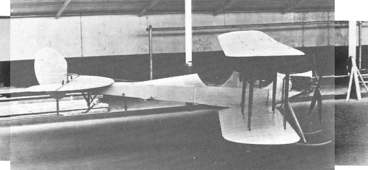
RAF BE.2a. The first machine built by Armstrong Whitworth & Co. in the Gosforth factory in 1913-1914. One of many contractors which built BE types.
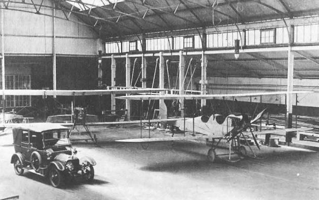
Armstrong Whitworth built B.E.2as in the converted skating rink at Gosforth. Just discernible, in the left-hand corner of the picture, behind the Armstrong Whitworth car, is the airship gondola built in 1914 to the order of the Admiralty for HMA No.2.
The B.E.2a, B.E.2b and B.E.2c
<...>
After the outbreak of war in 1914, the B.E.2a and the B.E.2b soon gave place to the better-known B.E.2c, which was built in large numbers by numerous contractors, including Armstrong Whitworth. The B.E.2c, which was designed to have automatic stability, according to the ideas of T. E. Busk, had a fuselage similar to that of the B.E.2b, but the wings were of new design, being heavily staggered and with ailerons on all four planes; the new tailplane was rectangular and a vertical fin was added to the rudder. Early examples of the B.E.2c had the 70 hp Renault engine and the characteristic undercarriage skids, but later production models were powered by the 90 hp RAF la engine and had a simplified V-type chassis. The B.E.2c gave good service as a reconnaissance aircraft in the opening stages of the war, but it was quickly outclassed and soon became an easy victim of enemy fighters.
Armstrong Whitworth built eight B.E.2as and twenty-five BE2bs but it has not been possible to trace the Service numbers of these aircraft. The total number of B.E.2cs built by Armstrong Whitworth is uncertain, but two batches built at Gosforth, amounting to 50 aircraft, carried the serial numbers 1780 to 1800 and 2001 to 2029.
B.E.2c
Span: 37 ft 0 in (11.28m)
Length: 27 ft 3 in (8.31m)
Wing area: 371 sq ft (34.47 sq m)
All-up weight: 2.142 lb (972 kg)
B.E.2c aircraft on the assembly line at Gosforth during the early months of 1915. On the left is the fuselage of the F.K.I single-seat biplane.
The R.E.7
It was in 1917 that the Siddeley Deasy Motor Car Company in Coventry received its first contract to build aeroplanes, the order being for one hundred R.E.7 biplanes. The R.E. series of aircraft was developed by the Royal Aircraft Factory at Farnborough to fill the need for an aircraft to work in co-operation with the army, the initials R.E. standing for reconnaissance experimental. Some measure of automatic stability was considered to be an essential requirement for this particular duty, and T. E. Busk, at the Factory, had spent much of his short career developing this characteristic in the early B.E. and R.E. aircraft.
The R.E.7, which appeared in 1915, was a large biplane with two-bay wings and with the top plane extensions braced by outward-sloping struts. A variety of engines were fined to the R.E.7, but most production aircraft had either the 160 hp Beardmore or the 150 hp RAF 4a. This latter engine was already being built by Siddeley Deasy in Coventry and, logically, was the powerplant selected for the R.E. 7s built by the company. Structurally, the R.E.7 was of interest by reason of the fact that steel tubing was used in fabricating the forward part of the fuselage; otherwise the method of construction was conventional except for the undercarriage, an elaborate affair with oleo shock-absorbers and a small wheel projecting in front of the propeller instead of the more usual skid.
Because of its large wing area, the R. E.7 was a good weight lifter and it was, in consequence, used principally as a bomber carrying the big 336-lb bomb designed by the Royal Aircraft Factory. During its brief operational career, the R.E.7 dropped a number of these bombs with good effect during 1916.
The R.E.7s built by Siddeley Deasy carried the serial numbers 2348 to 2447. The first to be built, 2348, was initially fitted with the RAF 4a engine, but this was later replaced by the 160 hp Beardmore; at the same time the aircraft was experimentally modified into a three-seater.
Span upper: 57 ft 0 in (17.37m)
Span lower: 42 ft 0 in (12.80m)
Length: 31 ft 11 in (9.73m)
Height: 12 ft 7 in (3.84m)
Wing area: 548 sq ft (50.91 sq m)
All-up weight: 3,450 lb (1,565 kg)
The R.E.8
The R.E.8, which followed the R.E.7 on the production line at the Siddeley Deasy Coventry factory, although designed for reconnaissance duties, bore little resemblance to any of the R.E. series of aircraft that had gone before. Unfortunately for those who had to fly in it, the R.E.8 perpetuated the philosophy that a reconnaissance aeroplane should be inherently stable, and it therefore lacked the manoeuvrability which would have improved its defensive capabilities; it did, however, have the crew correctly placed, with the pilot in front of the observer, who could thus use his gun to protect the aircraft from stem attacks.
The R.E.8 gained a bad reputation from the start: its performance was not up to expectations and it seemed to have a dangerous tendency to spin; furthermore, when it appeared on the Western Front during 1917 it suffered heavy losses from enemy fighters. It was, nevertheless, produced in large numbers, more than 4,000 being built by numerous contractors, and it remained in front-line service until the end of the war, giving invaluable support to the army both in France and in the Middle East by artillery spotting, photography and bombing.
The R.E.8 was conventional both in design and construction and was built of wood with fabric covering. The heavily-staggered, single-bay biplane wings were of unequal span, with the extension wings braced by wires. The engine was the 150 hp RAF 4a. Ailerons were fitted to all four wings and the tail surfaces were conventional with a rather small vertical fin. Later production models had a larger fin with a consequent improvement in the aircraft's spinning characteristics.
The Siddeley Deasy Motor Car Co, having already proved its capabilities with the R.E.7, was an obvious choice as contractor for the R.E.8, particularly as the RAF 4a engine was being built in the company's Parkside factory. Siddeley Deasy received its first order, for one hundred R.E.8s, towards me end of 1916, and this was followed by eight repeat orders, the total output by Siddeley Deasy amounting to 1,027 aircraft, with the production rate rising eventually to about twenty machines a week.
The R.E.8s built by Siddeley Deasy were numbered as follows: A3405-3504, A3681-3830, B6451-6624, B6628-6630,* B7681-7730, E1-300, E1151-1250, F 1553-1602 and F3246-3345
* These three aircraft were included in the contract for conversion to R.T.Is. but were probably completed as R.E.8s.
Span upper: 42 ft 8 in (13.00 m)
Span lower: 32 ft 8 in (9.96 m)
Length; 27 ft 10 in (8.48 m)
Height: 10 ft 10 in (3.30m)
Wing area: 377.5 sq ft (35.02 sq m)
All-up weight: 2,870 lb (1.302 kg)
R.T.1
At the time of Green's and Lloyd's move to Coventry, the factory was occupied with large-scale production of the R.E.8, one of the aircraft which Lloyd had worked on while still at Farnborough: it was appropriate, therefore, that this was the aeroplane that formed the basis for the design that was the first to carry the Siddeley Deasy name. Known as the R.T.1, this aeroplane was an attempt to improve on the R.E.8 which, in the RFC, had earned a reputation, not altogether justified, for shedding its overhanging top wing in a dive; it was also reputed to have a dangerous tendency to spin. It was probably more in an endeavour to eliminate these characteristics, rather than to improve the performance, that was the purpose behind the R.T.1 design.
The fuselage of the R.T.1 was essentially the same as that of the R.E.8, but the wings were of entirely new design, being of equal span with two-bay bracing and with the top wing having a greater chord than that of the bottom. Modifications to the fuselage consisted only of raising the observer's gun-ring by a few inches and providing a deeper fuselage top fairing to match. The horizontal tailplane was similar to that of the R.E.8, but the fin and rudder were both of greater area and with a more rounded shape. The small ventral fin of the R.E.8 was retained.
Only three R.T.1s were built, each one growing from a fuselage taken from a batch of 150 R.E.8s then on the Siddeley Deasy production line. The first R.T.1 was powered by a 200 hp Hispano-Suiza engine and fitted with a nose radiator similar in appearance to that of the S.E.5; it bore the serial number B6625. The second aeroplane, B6626, had the same engine as the R.E.8, an RAF 4A, developing 150 hp, in a standard R.E.8 mounting, whilst the third aircraft, the final version, reverted to the 200 hp Hispano-Suiza engine, this time enclosed in a neatly rounded cowling with an underslung radiator. In this version, as with the RAF-powered aircraft, the engine exhaust gases were discharged over the top wing by means of twin stacks. The third aircraft also had modified wingtips and horn-balanced ailerons with rounded tips.
The first flight of the R.T.1 was made from Radford aerodrome by J. H. James, later to become well known for his exploits with the Gloster 'Bamel' racer. He had with him as passenger the designer John Lloyd, who vividly recalls that a prolonged spin made this first flight more memorable than most. The date of the first flight is uncertain, but it is known that the second aircraft, the one with the RAF engine, was undergoing official tests by December 1917.
As compared with the R.E.8, the wing area of the R.T.1 was increased by some 12 per cent, with a wing loading of 6 lb/sq ft, as against nearly 7 lb/sq ft in the case of the R.E.8. In spite of this, the R.T.1 with the same engine was as fast as the R.E.8, clocking 101 mph at 6,500 ft, but, as might be expected, the climb performance was better, the R.T.1 reaching an altitude of 10,000 ft in 19.2 min, while the service ceiling was 16,000 ft, some 2,500 ft higher than that of the R.E.8. The view forward and downward from the pilot's seat of the R.T.1 had been criticized and to improve it a gap was cut in the lower wing root; this had the effect of reducing the speed by about 2 mph at 15,000 ft and increasing the time taken to reach 10,000 ft by about 3 1/2 min. The R.T.1 with the 200 hp Hispano-Suiza engine, and in its final form with the rounded nose, was tested in March 1919 and proved to be some 10 mph faster than the earlier version and to have a service ceiling higher by some 2,000 ft. The aircraft was reported to handle well and one of them underwent Service trials on the Western Front, whilst the other two went to training units; however, it must have been fairly clear from the start that there was little prospect of the R.T.1 going into production, and it seems probable that the design was undertaken more as an exercise for the newly established Siddeley Deasy design team than as a serious attempt to find a replacement for the R.E.8.
R.T.1
Dimensions: Span 41 ft 9 in (12.73 m); length 27 ft 8 in (8.43 m); height 11 ft 7 in (3.53 m); wing area 433 sq ft (40. 23 sq m).
150 hp RAF 4A 100 hp Hispano-Suiza
Max weight: 2,590 lb (1,175 kg) 2.707 lb (1,228 kg)
Empty weight: 1,773 lb (804kg) 1,803 lb (818kg)
Max speed
6,500 ft(1,981 m): 101 mph (163 km/hr}
10,000 ft (3.048 m): 98 mph (158 km/hr) 108 mph (174 km/hr)
15.000 ft (4.572 m): 91 mph (147 km/hr) 100 mph (161 km/hr}
Climb
to 6.500 ft (1,981 m): 10.5min 10.6min
to 10.000 ft(3.048 m): 19.2min 18.5 min
to 15,000 ft(4,572m}: 41.5min 36.4 min
Service ceiling: 16.000ft(4.877m} 18.000ft(5,486 m)
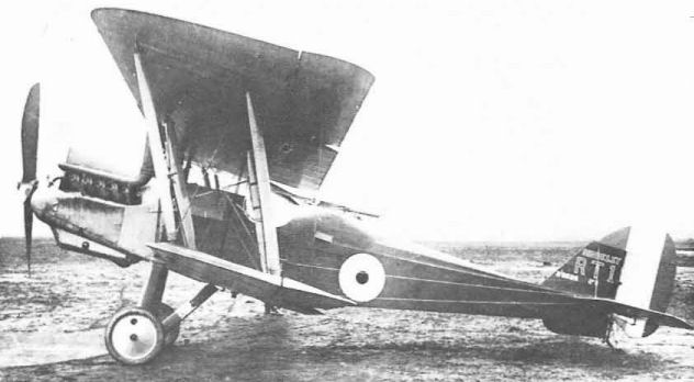
The Siddeley R.T.I was a redesign of the R.E.8. This aircraft, B.6626, had a 150 hp RAF 4A engine.
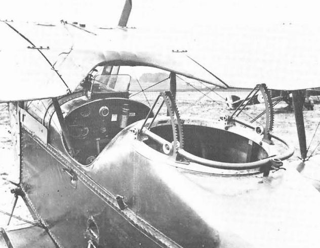
The cockpits of the R.T.1. This was John Lloyd's first design for The Siddeley Deasy Motor Car Co.