
Книги
Putnam
C.Andrews
Vickers Aircraft since 1908
117
C.Andrews - Vickers Aircraft since 1908 /Putnam/
The Maxim Flying Machine
Although Vickers were not directly concerned with the flying machine invented by Hiram S. Maxim, an American living in England, a short note is presented here of his pioneering efforts in aeronautics, because of his subsequent association with Vickers, Sons and Maxim Ltd. His firm, Maxim Nordenfelt Guns and Ammunition Co Ltd was acquired by Vickers Sons and Co Ltd in 1897, and his original Maxim machine-gun was developed into the Vickers gun, which was widely used in military aircraft.
Maxim's aeroplane was an ungainly structure with five sets of wings, the three centre pairs of which could be removed to vary the wing area from 5,400 to 4,000 sq ft. The total weight of the machine was about 4,000 lb, and it was powered with two compound steam engines fed by a water-tube boiler. They developed 363 hp each and drove a propeller of 17 ft 10-in diameter at 375 rpm. The weight of each engine was about 320 lb, but the boiler added some 800 lb. This boiler was mounted on a midships platform which also carried the crew of three, with the controls and water tanks. The overall span was 125 ft and the length was 104 ft.
The Maxim machine was tested by its inventor in Baldwyn's Park, Bexley, Kent, in July 1894. It was mounted on a specially constructed railway track of 9-ft gauge, with a secondary wooden track of 35-ft gauge on the outside inverted to prevent the machine rising more than a few inches for the preliminary experiments.
As with other early attempts to fly a heavier-than-air craft, evidence was obtained that Maxim's machine did rise off the ground. But the uncontrollability common to all attempts prior to the Wright brothers became catastrophic during the first trials and the machine was wrecked, without injury to Maxim and his assistants. It had cost Maxim over ?20,000. Later he became a British citizen and was knighted.

Hiram Maxim's flying machine after its crash.

B.E.2c No. 1760, the first production aircraft built at Weybridge.
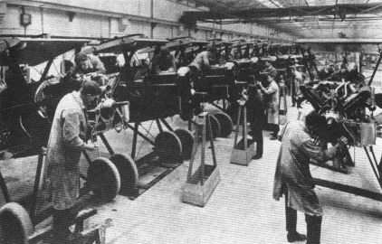
S.E.5a fighter production in the first world war at the Birmingham works of Wolseley Motors, then a Vickers subsidiary.

S.E.5a production at Weybridge in the first world war; 1,650 were made there, by far the highest total in the country.

Vickers S.E.5a development of 1921 with Wolseley Viper, Vixen-type radiator, oleo undercarriage and dihedral on bottom wing only.
The Early Monoplanes
Vickers, Sons and Maxim presented a strong case to the Admiralty on 3 January, 1911, offering to supply one Pelterie-type monoplane for ? 1,500. They stressed the point that the framework of the proposed machine, except the wings, was of steel, with a possible substitution of duralumin in later models. In reply, the Admiralty expressed disinterest, and consequently no order materialised. This approach was of some historical significance, for it presaged the adherence of Vickers to advanced structural philosophies and to metal construction in particular. At that time there were few metal aeroplanes.
The metal-tube airframe was indeed the only outstanding characteristic of the early Vickers monoplanes. Beyond the fact that they were quite strong for the performance then prevailing, they had little else to commend them. They were heavy for the limited power of the standard R.E.P. engine, and attempts were made to improve their power/weight ratio by using Gnome or other engines of greater power. The small margin between flying and stalling speeds made them tricky to fly, especially with the lack of power and the absence of inherent stability, the problems of which had still to be solved at that time.
Those were the pioneering days. The hardy aviators who took to the air in flying machines had perforce to learn the hard way. The Vickers monoplanes, with their steel-tube fuselages, were capable of absorbing rougher usage than contemporary wooden aircraft. With their rigid airframes they were also more easily transported, whereas wooden aircraft were easily damaged in transit.
No. 1 monoplane was part Pelterie (rear fuselage), but the rest was of Vickers construction. Comparing the standard R.E.P with Vickers' first effort, various small modifications appear to have been made. One of the difficulties encountered in building French aircraft under licence was the conversion of metric mensuration into feet and inches, consequently most of the original drawings had to be redrawn to British practice, although it is true that certain constructors, like Bristol and Martin-Handasyde, adopted the metric system throughout their original designs.
The first monoplane was built in the Erith works of Vickers, Sons and Maxim and not at Barrow-in-Furness as was suggested in the proposals to the Admiralty. H. F. Field was works foreman in charge, and he controlled a small number of workers detailed from general engineering jobs and having no previous experience in aircraft construction. This was a situation that was to reappear later on a much greater scale in aeronautical history, especially in the two world wars.
Capt Herbert F. Wood, who had been appointed manager of Vickers' aviation department on 28 March, 1911, made the first flight from a new private aerodrome established by Vickers at Joyce Green, near Dartford, Kent, and adjacent to the Long Reach Tavern by the River Thames. All Vickers' experimental test flying was made from this site right up to the Vimy Commercial of 1919. However, soon after this first flight in July 1911, the No. 1 monoplane was taken to Brooklands and flown there.
Early in 1912 the Vickers Flying School was established at Brooklands in sheds near the Byfleet banking, where later the final erecting shops of Hawker Aircraft Ltd were situated. After the successful trials of No. 1 monoplane, more were developed from the basic design and gave good service in the Vickers School as instructional machines.
No. 1 was written off in a crash.
Monoplanes Nos. 1-7
Nos 1, 2 and 3
Accommodation: Pilot and passenger
Engine: 60 hp R.E.P.*
Span: 47 ft 6 in
Length: 36 ft 5 in
Wing Area: 290 sq ft
Empty Weight: 1,000 lb
Gross Weight: -
Max Speed
at Ground Level: 56 mph
Range: -
* Changed to 60 hp Vickers-REP on No. 2.
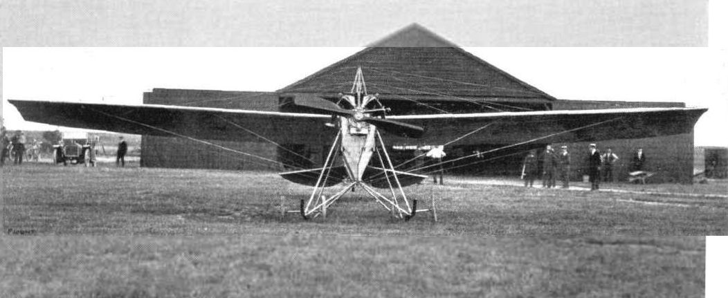
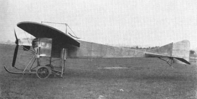
Vickers first aeroplane, the No. 1 monoplane, before its first flight at Joyce Green, Dartford, July 1911.
<...>
Among the designs emerging from Vickers' drawing office at that time from which an attempt was made at actual construction was No. 14, known as the Hydravion, presumably because it was intended for operation off land or water. Duralumin floats for the Hydravion were made at Vickers' Dartford works and were tested for corrosion in the adjacent River Darent. According to records held by Vickers House, the whole machine was intended to be made at Dartford, although there is some doubt about this, since the factory there was concerned with explosives and projectiles; most early Vickers aircraft were, in fact, constructed at Erith.
The Hydravion was a large biplane designed on Farman lines, with the 100 hp Gnome engine mounted at the back of the nacelle and driving a pusher propeller, the tail being supported on outrigger booms. A pilot and three passengers were carried. One version was made - the seaplane, according to Vickers House - and as this crashed on an early test flight no photographs have been located. The estimated maximum speed was 51 1/2 mph and the stalling speed 32 mph.
Further developments of the Hydravion included one designated No. 14B. This was projected with two 100 hp Gnome engines, buried in the fuselage, driving tractor propellers through shafts and gearing, with provision for the disengagement of one or other engine, the remaining one still driving both propellers. There was a crew of three, and a 37-mm semi-automatic cannon, with a magazine of 50 shells, was to be mounted in the nose.
Hydravion - One 100 hp Gnome. Accommodation pilot and three passengers. Span 72 ft 8 in; length 43 ft; height 12 ft 2 in; wing area 819 sq ft. Gross weight 2,400 lb. Max speed at ground level 51.5 mph.
<...>
Early in 1912 the Vickers Flying School was established at Brooklands in sheds near the Byfleet banking, where later the final erecting shops of Hawker Aircraft Ltd were situated. After the successful trials of No. 1 monoplane, more were developed from the basic design and gave good service in the Vickers School as instructional machines.
No. 1 was written off in a crash. No. 2 was sold to Dr (later Sir) Douglas Mawson for the 1912 Australian Antarctic expedition, but crashed on a trial flight in October 1911 at Adelaide; without its wings it was taken with the expedition as a tractor sledge, but the extreme cold solidified the lubricating oil and the engine seized, so the vehicle never served any useful purpose. However, as a pioneering winterisation test, the steel-tube fuselage stood up so well that in recent years, according to report, its remains have been observed at Cape Denison, the Antarctic base of the expedition.
The first five Vickers monoplanes were shoulder-wing aeroplanes carrying a pilot and passenger (or pupil). The fuselages were of steel tubing with welded and bolted tubular end-fittings at the joints, braced with piano wire and covered with fabric. According to Archie Knight, then an instructor at the School, doping was done by any agent that would tighten up the fabric, various concoctions being tried until the advent of acetate dopes as developed by Dr J. E. Ramsbottom of the Royal Aircraft Factory and by various companies in the paint trade.
The undercarriages of the first Vickers monoplanes had dual wooden skids and four wheels sprung by elastic cord on a lever system at the top of the legs. As was common at the time, lateral control was by wing warping. Various engines and propellers were experimented with, but usually Vickers-built R.E.P. five-cylinder fan radials with air cooling were fitted, reputed to be of 60 hp each. Maximum speed attained was around 56 mph and the empty weight about 1,000 lb. No. 5 monoplane was deeper bodied, which gave the crew more protection from the elements, and various small geometrical changes were made between the individual aircraft, including fin and stabiliser configuration.
<...>
In No. 7 monoplane, Vickers' designers reverted to the earlier and larger layouts with tandem seating, a two-skid four-wheel undercarriage and a 100 hp Gnome rotary engine as power unit.
Monoplanes Nos. 1-7
Nos 1, 2 and 3 No. 6 No. 7
Accommodation: Pilot and passenger Pilot and passenger Pilot and passenger
Engine: 60 hp R.E.P.* 70 hp Viale** 100 hp Gnome
Span: 47 ft 6 in 35 ft 34 ft 6 in
Length: 36 ft 5 in - 25 ft
Wing Area: 290 sq ft 220 sq ft 220 sq ft
Empty Weight: 1,000 lb - 730 lb
Gross Weight: - - 1,200 lb
Max Speed
at Ground Level: 56 mph 63 mph 70 mph
Range: - - 350 miles
* Changed to 60 hp Vickers-REP on No. 2.
** Changed to 70 hp Gnome rotary.
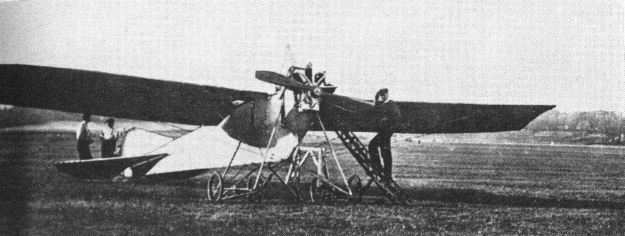
No. 2 monoplane at Brooklands in 1911 - the primitive giraffe-type servicing steps are interesting.
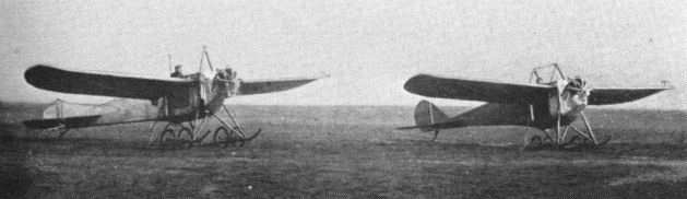
Nos. 3 and 5 monoplanes taxying at Brooklands - No. 5 has the deeper body - No. 4 closely resembled No. 3.

No.5 monoplane flying at Brooklands.
Side view of No. 7 disclosing reversion to the elaborate well-sprung four-wheel undercarriage of Nos. 1 to 5.
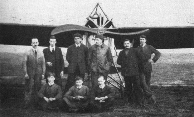
Staff of Vickers Flying School at Brooklands, pre-first world war, posing in front of Vickers-REP Monoplane; under propeller boss, R. H. Barnwell, chief instructor, also with cap, Archie Knight, assistant instructor.
<...>
Extensive redesign was introduced in the No. 6 monoplane, built at Erith in June 1912 for the Military Aeroplane Trials Competition, held on Salisbury Plain that year by the War Office. In the No. 6 the wing span was reduced and the undercarriage simplified by the adoption of a two-wheel arrangement with one central skid. Crew seating was side by side, which led to the unofficial designation of the monoplane as the Vickers Sociable. One of the requirements of the Competition was that both members of the crew should be provided with the best possible view of the ground in a forward arc, as the aeroplane was regarded then mainly as an instrument for supporting reconnaissance by cavalry.
No. 6 was powered by a 70 hp Viale seven-cylinder air-cooled radial engine, but this proved too unreliable to give the aeroplane a reasonable chance in the Competition, in which it was flown by L. F. Macdonald, Vickers' pilot. From this type a two-seat biplane was developed and test flown from Joyce Green in December 1912. It was in this aircraft that Macdonald, with his mechanic H. England, crashed in the Thames on 13 January, 1913, both occupants being drowned. The accident was attributed to failure of the 70 hp Gnome rotary engine, which type of engine had previously replaced the Viale in No. 6. No photographs or drawings have survived of this biplane conversion.
<...>
No. 8, the last of the early monoplanes built, reverted to the configuration of No. 6, with a 70 hp or 80 hp Gnome rotary engine as power. It was displayed at the Fourth International Aero Show at Olympia in February 1913. At the next Aero Show, also at Olympia in 1914, Vickers showed a two-seat scout biplane of wooden construction which was obviously a development of the earlier biplane of 1913. Here again few details were released, except that its estimated speed was 100 mph. Presumably this design was dropped in favour of the development of the Vickers Gunbus, which had become a priority for active service.
The following extract is taken from Flight for February 1913, and is a description of the typical construction of the Vickers monoplanes, couched in the terminology of the period. It refers to No. 8 as exhibited in the Aero Show of that year.
'The 80 hp Vickers Two-seater Monoplane - This monoplane is of the same type as the one which, fitted with a 70 hp stationary Viale motor, put up such praiseworthy flights at the time of the Military Aeroplane Competitions in August last. The identical machine shown, driven by a 70 hp Gnome motor, has done upwards of 500 miles in the air at the Vickers private flying ground at Erith, piloted by the late Mr Leslie Macdonald and by their present pilot instructor, Mr Barnwell.
'Its body is an all-steel structure, built lattice-girder fashion, with light tubular longitudinals and tubular cross members. They are assembled by means of welded steel sockets, the joints being afterwards sweated together and pinned. At the front end the four longitudinals meet in a flat upright prate, which serves as one of the mounting plates of the motor. Further support for the motor is provided by a stout flanged plate arranged some little distance behind the front cap. Seats are provided for the pilot and passenger side by side, and there are transparent wind shields fitted in front of them, so that they may suffer no inconvenience from the propeller draught. So carefully has this been carried out that when the machine is flying the occupants can detect scarcely any wind at all. Dual control is fitted. The seats are arranged well forward in the body, so that the occupants have a good clear view over the leading edge of the wings. To still further increase their range of vision, Cellon windows are let into the sides of the body. An interesting fitting in the cockpit is a Clift anti-drift compass, which is mounted over a hole in the floor and by which the machine may be kept on a true course in a side wind.
'The landing chassis is of the central skid and double wheel type. Two Vs of stout steel tube support the body from a long ash skid, which is curved up in front and which is armoured by the application of Duralumin sheeting. Two axles, carrying the rolling wheels, extend on either side of the skid. Landing shocks are absorbed by elastic springs in tension.
'The wings are built about two tubular steel spars cored with wood. Over them the ash ribs are loosely fitted in such a manner that continual warping of the wings does not tend to weaken them in any way. On the under side of the wings three stranded steel cables proceed to each spar, and these take the main lift. In a similar manner the wings are braced from above to a cabane above the pilot's cockpit.
'The tail is formed by the splaying out of the body at the rear to give a fixed stabilising surface behind which are hinged the two lifting flaps. On this monoplane, as distinct from the one that flew in connection with the Military Competitions at Salisbury, a vertical fin is fitted, which precedes an unbalanced directional rudder. A small steel skid protects the tail unit, but it is probable that it very seldom comes into play, for most of the weight of the tail on landing is taken by the backward laminated extension of the main landing skid.
'Fitted with an engine of 70 hp this monoplane shows a speed of 63 mph, and is capable of climbing with the useful load aboard of pilot, passenger, and sufficient fuel for a 3 1/2-hours' flight at the rate of 250 ft per minute. With an 80 hp Gnome motor installed, the machine has been timed to attain and maintain a speed of over 70 mph.'
The early Vickers monoplanes, supported by three Vickers Boxkites of Farman biplane genus, earned their keep despite the hazards of their low-powered engines of dubious reliability and the local physical obstructions to low-altitude flying at Brooklands in the wooded uplands of nearby St George's Hill and Weybridge Heath. There was also the notorious sewage farm, located inside the motor-racing track towards the railway embankment, ready to receive into its sticky mire the unwary flier in trouble on take-off or approach. The monoplanes competed in the popular flying meetings held at Brooklands in pre-1914 days and were always prominent in the handicap races flown on a circuit out to Coxes Lock Mill, near Addlestone, and back. Those halcyon afternoons of real peacetime aeronautics are fast fading from living memory.
Vickers Flying School at Brooklands trained 77 pupils between 1912 and 1914, the second highest of all the civilian schools in the country, and was only bettered by the Bristol School, who also trained most of their pupils at Brooklands. From January to August 1914, when Vickers School closed down because of the outbreak of war, it produced 36 pilots with aviators' certificates - popularly known as flying tickets. This was the record for the country, and the list of Vickers pupils contained names of pilots who achieved fame later on. The work of the pre-1914 civilian flying schools contributed much to the air services by way of trained pilots in the critical early period of the first world war.
Meanwhile Vickers went on with their development of metallised airframes as pioneered by the R.E.P. type monoplanes and with the evolution of a gun-carrying pusher biplane as well as various attempts to find a satisfactory alternative engine to the ubiquitous Gnome.
Monoplanes Nos. 1-7
Nos 1, 2 and 3 No. 6 No. 7
Accommodation: Pilot and passenger Pilot and passenger Pilot and passenger
Engine: 60 hp R.E.P.* 70 hp Viale** 100 hp Gnome
Span: 47 ft 6 in 35 ft 34 ft 6 in
Length: 36 ft 5 in - 25 ft
Wing Area: 290 sq ft 220 sq ft 220 sq ft
Empty Weight: 1,000 lb - 730 lb
Gross Weight: - - 1,200 lb
Max Speed
at Ground Level: 56 mph 63 mph 70 mph
Range: - - 350 miles
* Changed to 60 hp Vickers-REP on No. 2.
** Changed to 70 hp Gnome rotary.

No. 8 monoplane in Vickers Erith works, showing balanced elevators and sociable side-by-side seating first exploited in No. 6.
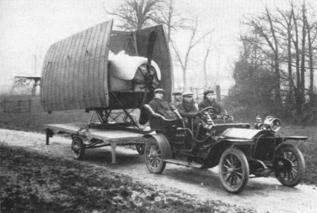
No. 8 monoplane packed for field transport on trailer and complete with ground crew in Napier car.
<...>
From this 14B and other designs on the same lines it may be concluded that Vickers were thinking in terms of a pusher aeroplane with offensive capability. The linking of their interests in armaments and aviation achieved practical recognition on 19 November, 1912, when a contract was received from the Admiralty for an experimental fighting biplane, armed with a machine-gun.
After many layouts had been considered, the Vickers designers decided that the only practical one was the pusher biplane with the gunner located in the nose. This marks the beginning of the era of Vickers military aircraft, for the design was later classified as E.F.B.l (Experimental Fighting Biplane No. 1) and named Destroyer. It was displayed at the Aero Show at Olympia in February 1913, and created great interest as the first gun-carrying aeroplane designed as such. Unfortunately, it crashed on taking-off on its first test flight at Joyce Green. The E.F.B.1 was powered by a 60/80 hp Wolseley eight-cylinder vee engine with water-cooled exhaust valves and air cooling for cylinders and inlets. The curious scimitar-shaped Vickers-Levasseur propeller was fitted.
The armament was a movable Vickers gun, lightened and modified so as to dispense with the water-cooling jackets of the infantry type, to give an unobstructed field of fire. The airframe was nearly all metal, the nacelle being of steel tubes covered with duralumin. The wings were staggered and employed warping for lateral control, as was then general practice.
Flight records the appearance of the E.F.B.1 at the Aero Show of 1913 as follows:
'The 60-80 hp Vickers Biplane. A very interesting machine, not only for the fact that, hitherto, the Vickers organisation have confined their attentions exclusively to monoplane construction, but for the great amount of thought and care that, it is evident, has been spent on its construction and design. Standing before this biplane, the first feature that arrests the attention is that there is a Vickers automatic gun protruding from the front of the neatly rounded Duralumin covered body. Then even the lay mind can arrive at the principal reason why the propeller has been placed at the rear of the machine - it is designed to have that position mainly in order to give an unobstructed range of fire in front of the biplane.
'The body of the machine, which extends forwards from the main planes, is constructed in a precisely similar manner to that of the Vickers monoplane'
'In its interior sits the passenger and, behind him, the pilot, both sheltered to a great extent from the wind by the neat metallic covering that is fitted over the body. Seated in front, the observer, and he will have to be a gunner too, has a perfectly clear view all around him. The gun before him is arranged to swivel through an angle of 60° in both horizontal and vertical planes, while the ammunition is stored in a box travelling on wires, beneath his seat. When the gun is not in use the ammunition box is in a position just over the centre of pressure of the planes; when it is required to operate it, the box is wound forward on its wire rails and brought within reach of the gunner. As we have remarked, the pilot sits immediately behind him, and he grips a double-handled vertical lever whereby he controls the machine. Still further behind, the motor is mounted, its lugs bolted to the top two members of the fuselage.
'The planes are made on a system which has little difference from that observed in the building of the Vickers monoplane wings. They are "staggered". Contrary to the more usual plan of using piano wire for the bracing of the planes, stranded steel cable is employed in this machine. As a matter of fact, all the bracing throughout is of stranded cable, excepting the body, where stout wire is used. The planes are so designed that in a very little time they may be dismantled, leaving only a centre section that is no wider than the body itself. Close examination of this central section of the top plane will reveal that in its interior there is a small petrol tank from which fuel is fed to the motor by gravity. It is supplied from a main tank in the body, under pressure, and the tubes leading to and from it are neatly tucked away behind the wooden filling pieces that are used to "streamline" the tubular cellule spars. By the way, the machine does not carry an oil tank, for sufficient oil is stored in the base-chamber of the motor to last for a six hours' flight.
'The landing chassis is, at first sight, very much like that of the monoplane. Its flexible suspension, however, will be found to be altogether different. A central hollow skid of ash is joined to the body by two Vs of steel tubing. Two other Vs of tubing extend downwards and outwards from the side of the body, and, in crutches, at their lower extremities, the axles of the landing wheels travel against the tension of the strong rubber springs. Altogether, the chassis is exceptionally light and compact, and, moreover, looks strong enough to bear any ordinary landing strain that it is likely to be subject to. Differing from the monoplane, too, there is no backward extension of the central landing skid. The weight of the tail is carried by a small steel spoon-shaped tail skid, so fixed that it pivots with the rudder and enables the machine to be steered more or less accurately over the ground at slow speeds.
'The tail, level with the top main plane in flight, is attached to the top of the tubular steel tail outriggers. In plan form it is approximately rectangular, and its interior construction is of steel throughout, tubing being used for its outline, while the cambered ribs are of channel section, acetylene-welded in position.'
<...>
Experimental work was carried out with the Gunbus concept, and the E.F.B.6 was a variant flown in 1914 with extended top wing, presumably to obtain more lift for load carrying, but was not proceeded with. Before that, an advanced project following the general configuration of the E.F.B. 1 Destroyer had been designed under the classification E.F.B.4.
E.F.B.1(Destroyer)
Accommodation: Pilot and gunner
Engine: 80 hp Wolseley
Span: 40 ft
Length: 27 ft 6 in
Height: 11 ft 11 in
Wing Area: 385 sq ft
Empty Weight: 1,760 lb
Gross Weight: 2,660 lb
Max Speed: 70 mph at ground level (est.)
Initial Climb: 450ft/min(est.)
Range: 4 1/2 hr
Armament: One Vickers
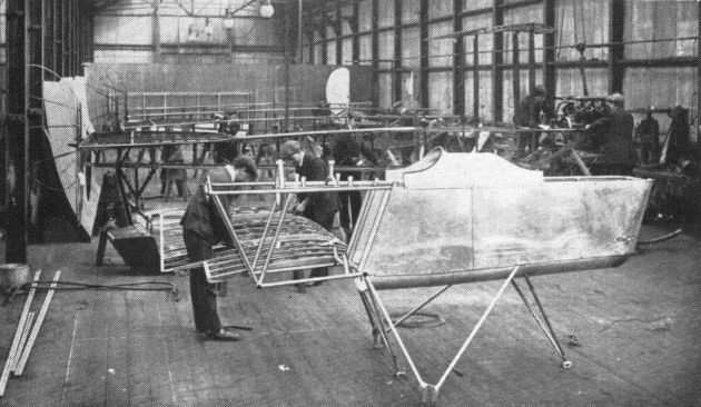
Vickers original fighting biplane under construction at Erith works only a few weeks before its public premiere at Olympia; on the right is the Wolseley engine, and in the background are B.E.2s being built.
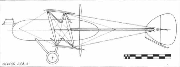
Vickers E.F.B.4
<...>
In 1913, Type 18, the E.F.B.2, appeared as an unstaggered biplane with slight overhang on the top wings and with large celluloid windows in the sides of the nacelle. It was flown frequently at Brooklands by Capt Wood and Harold Barnwell during that year, and was powered by a 100 hp Gnome monosoupape rotary engine. E.F.B.3 or No. 18B appeared in December 1913 with the side windows deleted and with ailerons replacing the wing warping. It was shown at the 1914 Olympia Aero Show. An order for six modified No. 18Bs, known as Vickers Type 30s, was placed in December 1913 by the Admiralty. However, before delivery was effected the Type 18B design was still further improved; the contract was taken over by the War Office, and this led to the prototype E.F.B.5, which retained the semicircular tailplane characteristic of the early Type 18.
<...>
Another Vickers design prepared early in 1914 was the S.B.1 school biplane, based on the E.F.B.3 but with the gunner's cockpit replaced with a pupil's position fitted with dual controls. The engine intended for this development was to have been the 100 hp Anzani static radial
E.F.B.2 E.F.B.3
Type 18 Type 18B
Accommodation: Pilot and Pilot and
gunner gunner
Engine: 100 hp Gnome 100 hp Gnome
monosoupape monosoupape
Span: 38 ft 7 in 37 ft 4 in
Length: 29 ft 2 in 27 ft 6 in
Height: 9 ft 7 in 9 ft 9 in
Wing Area: 380 sq ft 385 sq ft
Empty Weight: 1,050 lb 1,050 lb
Gross Weight: 1.760 lb 1.680 lb
Max Speed: 60 mph at 60 mph at
ground level ground level
Service Ceiling:
Initial Climb: 200 ft/min 300 ft/min
Range: 150 miles 300 miles
Armament: One Vickers One Vickers

E.F.B.3 with metal-sheathed nacelle at Brooklands in 1913 with Harold Barnwell, Vickers' chief pilot, in rear seat.
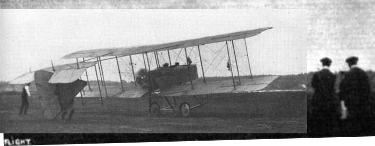
Experimental version of E.F.B.3 with revised fin and rudder and test instrumentation on starboard aileron strut.
Mr. Barnwell testing his engine before making a flight in the Vlckers gun-carrying biplane at Brooklands.
Mr. Barnwell testing his engine before making a flight in the Vlckers gun-carrying biplane at Brooklands.
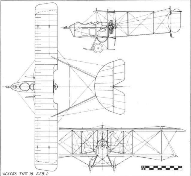
Vickers Type 18 E.F.B.2
The Evolution of the Gunbus
At first the only types of instructional aeroplanes used by Vickers Flying School were the various Vickers monoplanes. Towards the end of 1912, however, three Farman-type biplanes were purchased for pupil training from Vickers' next-door neighbours at Brooklands, Hewlett and Blondeau. With some reconstruction these biplanes became known as Vickers Boxkites and were numbered 19,20 and 21. In December 1913 an equal-span version of the Vickers Boxkite appeared, with a primitive enclosed nacelle to afford the instructor and pupil some protection from the wind. They sat side by side in staggered seats, and the odd-looking structure which resulted from this arrangement led to the aeroplane becoming known as the Pumpkin, bearing the Vickers number 26. A 50 hp Vickers-Boucier static radial engine was fitted, but this was eventually replaced by the 70 hp Gnome.
Vickers School Biplane - Boxkite - One 50 hp Gnome. Span 51 ft 3 in; length 39 ft; wing area 433 sq ft. Gross weight 835 lb.
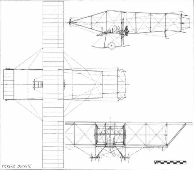
Vickers Boxkite
<...>
In 1913, Type 18, the E.F.B.2, appeared as an unstaggered biplane with slight overhang on the top wings and with large celluloid windows in the sides of the nacelle. It was flown frequently at Brooklands by Capt Wood and Harold Barnwell during that year, and was powered by a 100 hp Gnome monosoupape rotary engine. E.F.B.3 or No. 18B appeared in December 1913 with the side windows deleted and with ailerons replacing the wing warping. It was shown at the 1914 Olympia Aero Show. An order for six modified No. 18Bs, known as Vickers Type 30s, was placed in December 1913 by the Admiralty. However, before delivery was effected the Type 18B design was still further improved; the contract was taken over by the War Office, and this led to the prototype E.F.B.5, which retained the semicircular tailplane characteristic of the early Type 18. When this latest variant went into production the tailplane was made rectangular, and various nacelle configurations necessitated by different armament mountings were tried before the familiar blunt nose of the standard F.B.5 emerged. At this time the F.B.5 was dubbed the Gunbus.
It will be noted at this time that the prefix E, signifying experimental, was dropped. The first F.B.5 Gunbus was delivered to No. 6 Squadron of the Royal Flying Corps at Netheravon in November 1914. In it the lighter and handier Lewis gun replaced the Vickers gun (One or two F.B.5s used by the Royal Naval Air Service retained the Vickers gun on a pivot mounting), which, however, continued to be used in the air war as a fixed weapon with the whole aeroplane aimed at the target. Before this happened, however, a satisfactory means had to be invented to enable a fixed gun to fire through a revolving tractor propeller. One of the earliest of such devices was, in fact, the Vickers-Challenger interruptor gear. By this time aviation had become an arm of the Services, tentatively at first for reconnaissance and later for air attack.
The Crayford works took over the production of Vickers aircraft in late 1914, and the first F.B.5s were delivered from there. Three aircraft comprised the initial delivery to Netheravon, but two were returned to Joyce Green to create the nucleus of the Air Defence of London. The first recorded use of a Gunbus in action was on Christmas Day 1914, when 2nd Lt M. R. Chidson with Corporal Martin as gunner took-off from Joyce Green to attack a German Taube monoplane and, according to circumstantial evidence, destroyed it. The type went to the Western Front, and the first F.B.5 to arrive there was Chidson's, he having been posted to No. 2 Squadron in France on 7 February, 1915.
In November 1915, 2nd Lt G. S. M. Insall was awarded the Victoria Cross for gallantry displayed after forcing down a German Aviatik reconnaissance machine while flying a Vickers Gunbus. Compelled by ground fire to land near the front lines of the Allies, Insall repaired the damage to his aeroplane during the night and returned next morning to his squadron. In spite of these and other successes, the Gunbus suffered in company with other Allied aircraft from the unreliability of the rotary engine, largely because servicing and maintenance in the early days were not of the high standard reached later.
Experimental work was carried out with the Gunbus concept, and the E.F.B.6 was a variant flown in 1914 with extended top wing, presumably to obtain more lift for load carrying, but was not proceeded with. Before that, an advanced project following the general configuration of the E.F.B. 1 Destroyer had been designed under the classification E.F.B.4.
The F.B.5A was fitted with the Le Rhone or Clerget engine of 110 hp, and at least four were constructed with armour-plated nacelles. Two F.B.5s were fitted with the experimental Smith static radial air-cooled engine, nominally of 140 hp, while another was equipped with floats for operation off water but before this could be tried was reconverted to standard form and flown back to France.
<...>
A replica F.B.5 Gunbus was made by the Vintage Aircraft and Flying Association (Brooklands) in 1966 to celebrate the centenary of the Royal Aeronautical Society. It was fitted with a 100 hp Gnome monosoupape rotary engine rebuilt from two surviving examples found in RAF redundant stores. This aeroplane flew faultlessly at the first attempt, piloted by D. G. Addicott, a Vickers test pilot. Despite its low power, the replica disclosed good handling qualities and is an existing testimony to the excellence of the design for the requirement of its day, which was to provide a steady gun platform for air offence.
F.B.5 (Gunbus)
Accommodation: Pilot and gunner
Engine: 100 hp Gnome monosoupape
Span: 36 ft 6 in
Length: 27 ft 2 in
Height: 11 ft
Wing Area: 382 sq ft
Empty Weight: 1,220 lb
Gross Weight: 2,050 lb
Max Speed: 70 mph at 5,000 ft
Service Ceiling:9,000 ft
Climb to: 5,000ft in 16min
Range: 250 miles
Armament: One Lewis
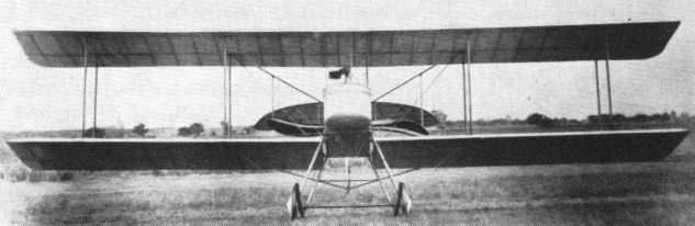
Head-on view of prototype E.F.B.5 revealing Levasseur-type propeller and semicircular stabiliser.
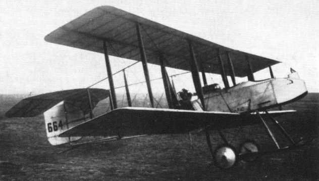
E.F.B.5 prototype in service under serial 664 with gun pylon added - sometimes described as F.B.4, although the E.F.B.4 was a project development of E.F.B.1.
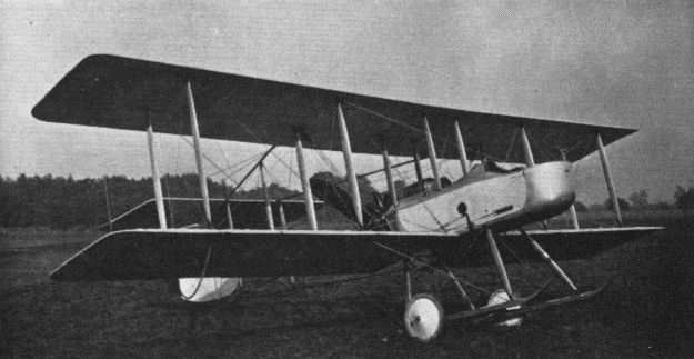
First production F.B.5 at Brooklands for trials before delivery. The two seat Vickers FB 5, popularly known as the 'Gun Bus', had its origins in a visionary 1912 Admiralty requirement for a so-called fighting aeroplane, armed with a machine gun. The contract for this machine was placed with Vickers on 19 November 1912, where its development became somewhat protracted, the first production FB 5s, by now ordered for both the RFC and the RNAS, not reaching No 6 Squadron, RFC until November 1914, while the handful of RNAS FB 5s did not reach the front until early 1915. Powered by a somewhat unreliable 100hp Gnome Monosoupape, the FB 5's top level speed was 70mph at 5.000 feet, while the time taken to reach that altitude was 16 minutes. Excluding prototypes, around 136 FB 5s are known to have been produced by Vickers in Britain and Darracq in France.

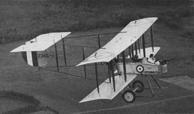
One of the first batch of F.B.5s for the Royal Flying Corps presented by the City of Bombay to H.M. Government in 1914; this Gunbus was the pattern for the replica built in 1966.
The replica Gunbus built by the Vintage Aircraft and Flying Association (Brooklands) on an engine test flight piloted by 'Dizzy' Addicott with Alan Blower as observer.

The replica Gunbus built by the Vintage Aircraft and Flying Association (Brooklands).
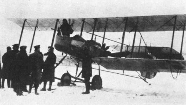
A Gunbus on the Western Front in 1915 in traditional Christmas conditions.
Vickers E.F.B.5

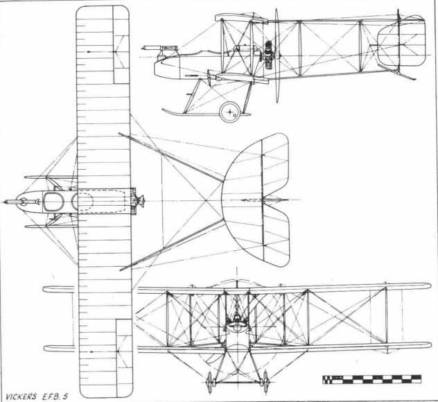
Vickers FB.5 (production)
<...>
Experimental work was carried out with the Gunbus concept, and the E.F.B.6 was a variant flown in 1914 with extended top wing, presumably to obtain more lift for load carrying, but was not proceeded with.
Experimental work was carried out with the Gunbus concept, and the E.F.B.6 was a variant flown in 1914 with extended top wing, presumably to obtain more lift for load carrying, but was not proceeded with.
F.B.6 at Brooklands in 1914 with large overhang on top wing braced by pyramid kingposts.
<...>
A side issue of some interest to the Gunbus story was the request from the German Government, made early in 1914, for details of Vickers fighting biplanes. Apparently there was nothing sinister in this approach, which was similar to that made to the Sopwith and other British aircraft companies; Britain was never seriously regarded as a potential enemy by Germany even at that late date, and its interest was doubtless genuine.
In offering the Type 18 series to the Germans, Vickers said, 'What we have at the present moment is a type of machine which is not existent in the German Army, in fact not in Europe except in England. This machine is intended for offensive action in the air against other planes and dirigibles, consequently it is not equipped with a bomb-dropping apparatus. The light Maxim gun mounted in the nose is so placed as to enable the gunner to have a free field of fire against other aeroplanes. We can carry Pilot, Observer, Barograph, Gun, 300 rounds of ammunition, and fuel for 4 hours. Loaded with this, it can easily attain a height of 800 metres in 15 minutes. The speed of the machine is 105 km/hr instead of 90 required by the German Authorities. We can reduce to 70 km/hr if required.'
This design was not accepted, but in response to a further request from the German Government, three advanced designs for aircraft, called G.F.B.1, G.F.B.2 and G.F.B.3 (German Fighting Biplanes), which resembled in many respects the Hydravion projects, were prepared during the early months of 1914. Details of only the last two are now available; these were alike, except that the G.F.B.2 had two 100 hp Gnome monosoupape engines while the G.F.B.3 had two 140/165 hp Austro-Daimlers. The engines were mounted side by side in the fuselage, driving two tractor propellers, and clutches could cut out one or both.
These large three-seat biplane designs had provision for a 37-mm one-pounder gun mounted in the nose, and the pilot and observer were seated in the fuselage behind the engines. Specified equipment included wireless and 50 rounds of ammunition. The upper wings were of greater span than the lower, and for hangarage purposes the outer sections of the upper wings could be lowered, thus reducing the span from 72 to 59 ft. The G.F.B.3 was designed for a maximum speed of 72 mph with an endurance of five hours, and the all-up weight was estimated at 4,000 lb. The outbreak of war in August 1914 prevented construction of these interesting designs.
Scout Biplane - One 100 hp Gnome monosoupape. Accommodation pilot and passenger. Span 25 ft; length 20 ft 7 in; wing area 270 sq ft. Empty weight 600 lb; gross weight 1,200 lb. Max speed at ground level 100 mph; range 350 miles.
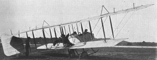
Shortly after the start of the first world war Vickers engaged Howard Flanders to design a new twin-engined fighting aeroplane to carry a Vickers one-pounder gun. Classified as the E.F.B.7, it was powered with wing-mounted Gnome monosoupape engines, and the pilot was seated behind the wings and the gunner in the nose. It flew some time in August 1915, and thus vied with the comparable French Caudron and other designs for the claim of being the first twin-engined military aircraft to fly successfully.
However, in the E.F.B.7 the distance separating the two-man crew was found unacceptable in practice; in the variant, the E.F.B.7A, the pilot was brought forward of the wings, just behind the gunner. An attempt to re-engine this Flanders-designed machine with two 80 hp air-cooled Renaults (because of the shortage of Gnomes) was unsuccessful, as the loss of some 40 hp meant a serious drop in performance. In consequence, a contract for 11 F.B.7 aircraft being built by Darracq and Company (1905) Ltd of Townmead Road, Fulham, was cancelled.
The E.F.B.8, which appeared in November 1915, powered by two Gnome monosoupapes, was smaller than its predecessor and carried only a single light Lewis gun, which could be accommodated equally well in single-engined types. This redesign was entrusted to Pierson, who stored the knowledge gained and revived it when a new twin-engined bomber was called for from Vickers by the Air Board in 1917.
E.F.B.7 E.F.B.8
Accommodation: Pilot and gunner Pilot and gunner
Engines: Two 100 hp Two 100 hp
Gnome monosoupape Gnome monosoupape
Span: 59 ft 6 in upper, 38 ft 4 in upper
37 ft 6 in lower 36 ft 8 in lower
Length: 36 ft 28 ft 2 in
Height: - 9 ft 10 in
Wing Area: 640 sq ft 468 sq ft
Empty Weight: 2,136 lb 1,840 lb
Gross Weight: 3,196 lb 2,700 lb
Max Speed at 5,000 ft: 75 mph 98 mph
Climb to 5,000 ft: 18 min 10 min
Ceiling: 9,000 ft 14,000 ft
Endurance: 2 1/2 hr 3 hr
Armament: One 1-pdr Vickers gun One Lewis gun
in nose in nose
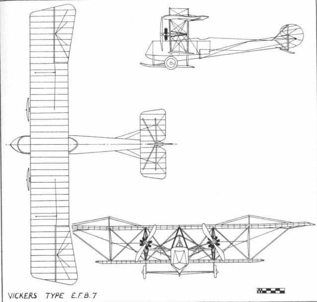
Vickers Type E.F.B.7
Vickers Designs 1914-18
When war broke out in 1914 there was a serious shortage of British military aircraft compared with those possessed by France and Germany, and various aeronautical experimenters made efforts to remedy this deficiency. Among these private-venture attempts was one by Harold Barnwell, who had been appointed chief test pilot by Vickers after the closing of their flying school at Brooklands. In spare moments from testing production Gunbuses he took upon himself the task of designing and constructing under cover a small high-speed scout, fitted with a Gnome engine spirited out of Vickers' Erith stores.
Barnwell's creation was a tubby little machine with a circular-section streamlined fuselage and stubby unstaggered wings of small span. It soon acquired the name of the Barnwell Bullet. On its first flight early in 1915, in the hands of its designer, it was found to have insufficient control, particularly on the elevators. On landing, its undercarriage collapsed, and the Bullet stood on its nose. This mishap must have revealed its existence to Vickers' management, for R. K. Pierson, a young graduate apprentice then in the drawing office who had also learned to fly at Vickers' Flying School, was given the task of redesigning the Bullet into an experimental scout with the designation of E.S.1, powered with a Gnome monosoupape engine.
E.S.1 had larger tail surfaces than those of the original Barnwell Bullet and a stronger undercarriage. No armament was carried. After a period of flight testing it was sent to the Central Flying School at Upavon for official trials. Certain disadvantages were disclosed, particularly in the pilot's view upwards as well as downwards over the side of the fat body. There was no drain hole in the engine cowling to jettison surplus oil and petrol vapour centrifuged by the rotary engine.
An improved version was then developed with the 110 hp Clerget rotary engine. A small window of celluloid was inserted in the top centre section to improve the pilot's view upwards, and the fairing was removed from the underside of the fuselage. In this form the type was known to Vickers as the E.S.2. (In official documents it appears as E.S.I Mk. II) Two were made, and one was used for trials of the Vickers-Challenger gun synchronising gear which enabled a fixed machine-gun to be fired through a tractor propeller. This gear was used operationally on the Sopwith One-and-a-half Strutter two-seat fighter. In the summer of 1916 one E.S.2, equipped with a forward-firing fixed Vickers gun and the synchronising gear, was sent to France for operational trials by No. 11 Squadron, RFC, then operating Vickers Gunbuses. There it kept company with a small number of Bristol Scouts, but reports on the Vickers Bullet, as the E.S.2 was known, confirmed the CFS opinion of the E.S.1 that it was too blind from the pilot's point of view. The E.S.2 was also flown before H.M. King George V during a visit to Vickers' Crayford works in September 1915 and demonstrated to a visiting Russian Imperial aviation mission.
E.S.1 - Barnwell Bullet rebuilt - One 100 hp Gnome monosoupape. Span 24 ft 4 1/2 in; length 20 ft 3 in; height 8 ft; wing area 215 sq ft. Empty weight 843 lb; gross weight 1,295 lb. Max speed 114 mph at 5,000 ft; climb to 10,000 ft - 18 min; endurance 3 hr. No armament.
E.S.2 - Bullet - One 110 hp Clerget. Span 24 ft 5 1/2 in; length 20 ft 3 in; height 8 ft; wing area 215 sq ft. Empty weight 981 lb; gross weight 1,502 lb. Max speed 112.2 mph at ground level; climb to 10,000 ft - 18 min; service ceiling 15,500 ft; initial climb 1,000 ft/min; endurance - 2 hr at 8,000 ft. Armament one Vickers gun (synchronised by Vickers Challenger interrupter gear).
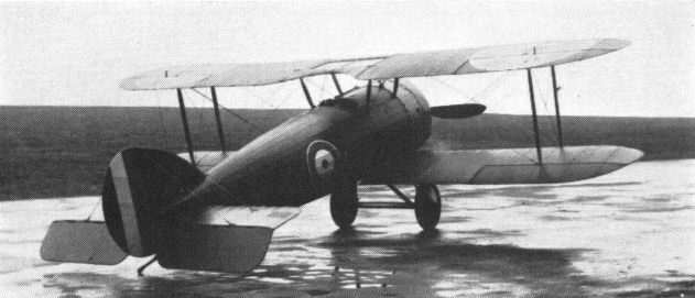
E.S.2 or E.S.I Mk II, according to taste, in its war paint ready for Service trials.
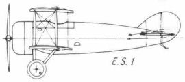
E.S.1
<...>
Last of the line to be made was the F.B.9, which was sufficiently sophisticated to be known as the Streamline Gunbus. A lot of cleaning up had had to be done, the wing tips and tailplane were neatly rounded off, the nacelle was of much better aerodynamic form and the older skid undercarriage (which incidentally had proved very useful on the early primitive landing grounds in France) was replaced by a V type. Streamlined, adjustable Rafwires (External bracing wires invented by the Royal Aircraft Factory. They were rolled, on specially designed machines, from round swaged steel rods to an oval streamline section to reduce drag) had replaced the stranded steel cables and turnbuckles of the earlier machines. Between June 1916 and September 1917, 95 F.B.9s were built and used mostly for training duties at home, as by then the much more powerful F.E.2d with a 250 hp Rolls-Royce Eagle I was available for overseas as a pusher fighter-bomber. One F.B.9 was especially modified as a trench-strafer with an armour-plated nacelle and an oleo undercarriage.
Some F.B.9s were used in the Battle of the Somme which started on 1 July, 1916. From the personal notebook of 2nd Lt Lionel Morris of No.l1 Squadron, RFC, it is learned that he and Lt Torre of the same squadron were detailed to collect 'Streamlined Gunbuses' from Villacoublay aerodrome near Paris on 25 June, 1916, as stand-ins for the Squadron's F.E.2bs fitted with the 160 hp Beardmore engine. This engine, which was a more powerful version of the 120 hp standard Beardmore, was giving continual trouble, leading to serious break-up of internal components, just at a time when every aeroplane was needed for the first major offensive of the Allies. It is probable therefore that French-built or French-assembled F.B.9s were used at that time by other RFC squadrons primarily equipped with the higher-powered Beardmore F.E.2bs.
In France, S. A. Darracq of Suresnes in fact made 99 F.B.5s and F.B.9s under licence, but an intention for Vickers' Italian subsidiary, Vickers-Terni, to manufacture the type fell through for political reasons. A further development, the F.B.10, was projected with the Italian 100 hp Isotta-Fraschini engine, but was not proceeded with, as Vickers designers were otherwise engaged in evolving the variety of experimental aircraft as described in the next chapter. In any case, the Gunbus was being outclassed by more advanced designs of fighting aeroplanes.
F.B.9
Accommodation: Pilot and gunner
Engine: 100 hp Gnome monosoupape
Span: 33 ft 9 in
Length: 28 ft 5 1/2 in
Height: 11 ft 6 in
Wing Area: 340 sq ft
Empty Weight: 1,029 lb
Gross Weight: 1,820 lb
Max Speed: 82.6 mph at sea level
Service Ceiling:11,000 ft
Climb to: 10,000 ft in min
Range: 250 miles
Armament: One Lewis
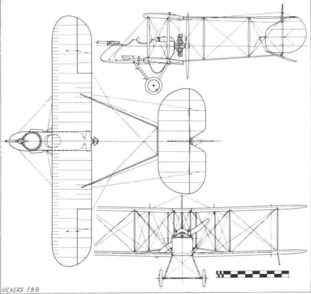
Vickers FB.9
<...>
Vickers fared a little better with their excursions into the tractor biplane field for multi-seat aircraft, after a poor start with the F.B.11 designed by Howard Flanders as a Zeppelin airship destroyer, for which purpose it had a fighting top mounted on the centre section of the upper wing. On a trial flight the F.B.11 proved to be deficient in control, and Harold Barnwell spent five weeks in Crayford hospital as a result. Its sole claim to distinction was that it was the first Vickers aeroplane to be powered with a Rolls-Royce engine, the early Eagle I of 250 hp.
F.B.11 - One 250 hp Rolls-Royce Eagle I. Span 51 ft; length 43 ft; height 15 ft; wing area 845 sq ft. Empty weight 3,340 lb; gross weight 4,934 lb. Max speed 96 mph at 5,000 ft; climb to 10,000 ft - 55 min; service ceiling 11,000 ft; absolute ceiling 12,000 ft; endurance 4 1/2 hr. Armament two Lewis guns.
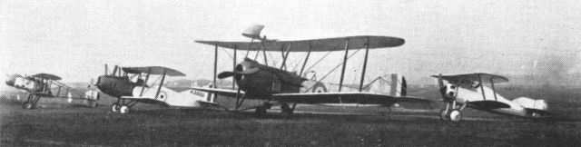
A line-up of Vickers experimental aircraft at Joyce Green; (left to right) F.B.12C, F.B.14, F.B.11, F.B.16.
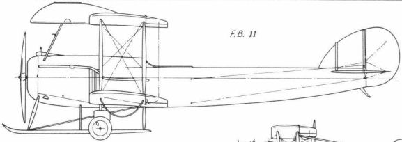
F.B.11
<...>
Also in the single-seat fighter class were the two Vickers pusher types, the F.B.12 and the F.B.26. Both had chequered careers. The F.B.12 was also intended for the 150 hp Hart static radial engine, but continual delays with this engine and the shortage of rotaries for experimental work led to the installation of an 80 hp Le Rhone taken from another aeroplane. The F.B.12 flew in June 1916, but, being underpowered, had a most disappointing performance. A 100 hp Gnome monosoupape was then substituted. Even in this guise, as the F.B.12A, it still had only two-thirds the designed power, and so lost any performance advantage it might have had (with the 150 hp promised from the Hart) over the D.H.2 and F.E.8 pusher fighters already in service, but it went to France in December 1916 for operational trials. The F.B.12B with the Hart engine was completed in February 1917, its wing span increased from 26 ft to 29 ft 9 in, but it crashed, thus helping to settle the fate of the Hart engine once and for all. A contract was placed with the Wells Aviation Company of Chelsea for the F.B.12C, and the few examples made were fitted with a variety of engines, including Gnome monosoupape, Le Rhone and the Anzani static radial, all nominally about 100 hp. The AID report on the first production example, A7351, was so critical, and disclosed a top speed of only 87 mph, that, coupled with the failure of the Hart, it could lead to nothing but a cancellation of the contract.
F.B.12C - One 150 hp Hart. Span 29 ft 9 in, upper, and 26 ft 9 in, lower; length 21 ft 10 in; height 8 ft 7 in; wing area 237 sq ft. Empty weight 927 lb; gross weight 1,447 lb. Max speed 87 mph at 6,500 ft; climb to 10,000 ft - 18 1/2 min; service ceiling 14,500 ft; absolute ceiling 15,000 ft; endurance 3 1/4 hr. Armament one Lewis gun mounted in nose of nacelle.
A line-up of Vickers experimental aircraft at Joyce Green; (left to right) F.B.12C, F.B.14, F.B.11, F.B.16.

F.B.12
<...>
In 1916 Vickers produced the F.B.14 general-purpose single-engined tractor biplane of smaller dimensions than those of the F.B.11, but bearing obvious Flanders influence, such as the single-bay wing cellule with a larger top wing and splayed-out struts. From the F.B.14 descended a lengthy line of tractor biplanes to be described in later chapters. Its steel-tube fuselage followed the early pattern derived from the R.E.P. type monoplane, and this feature created official interest, and on structural test at Farnborough it disclosed good strength factors. Although intended for the 200 hp B.H.P. engine (later to become the 230 hp Siddeley Puma), the F.B.14 was powered with the 160 hp Beardmore, which itself was proving unreliable enough for it to be replaced by the older 120 hp Beardmore. Thus once more the bogey of underpower appeared, and although 100 airframes were built at Weybridge, only relatively few ever received suitable engines. Intended as replacement for the B.E.2c, B.E.2d or B.E.2e in Middle East squadrons, an indefinite number of F.B.14s were reported as sent to Mesopotamia and seven are known to have been used by Home Defence squadrons.
Other variants to materialise were the F.B.14A with a 150 hp Lorraine-Dietrich, the F.B.14D with a 250 hp Rolls-Royce and the F.B.14F with a 150 hp Raf 4a, an air-cooled twelve-cylinder vee engine which was the standard power unit for the R.E.8 general-purpose aeroplane. The F.B.14D with the Rolls engine had increased span with two-bay wings, and on test at the new experimental aerodrome at Martlesham Heath, near Ipswich, it recorded a speed of 111.5 mph. Later it was used for gunnery trials at Orfordness on the Suffolk coast, fitted with a Vickers gun firing forwards and upwards at 45 degrees and two Lewis guns firing rearwards, one under the tail.
With an experimental periscopic gunsight for the pilot, the Orfordness F.B.14D chased a hostile raid back to the Belgian coast in July 1917, and obtained an unconfirmed victory over a Gotha bomber, which was seen to go down in the sea off Zeebrugge. (This account of the incident has been recently verified by Sir Vernon Brown, who was the pilot, and Sir Melville Jones, the observer, who had invented the gunsight. The pilot laid the sight on the target for the gunner to fire the guns. In the device, allowance had been made for relative speeds of the aircraft and for wind velocity)
F.B.14 - One 160hp Beardmore. Span 39 ft 6 in, upper, and 33 ft, lower; length 28 ft 5 in; height 10 ft; wing area 427 sq ft. Empty weight 1,662 lb; gross weight 2,603 lb. Max speed 99.5 mph at ground level; climb to 10,000 ft - 40 3/4 min; service ceiling 10,000 ft; absolute ceiling 10,600 ft; endurance 3 3/4 hr. Armament one Lewis gun and one Vickers gun.
F.B.14D - One 250 hp Rolls-Royce Eagle IV. Span 42 ft, upper, and 39 ft 6 in, lower; length 30 ft 8 in; height 10 ft 3 in; wing area 485 sq ft. Empty weight 2,289 lb; gross weight 3,308 lb. Max speed 111.5 mph at 6,500 ft; climb to 10,000 ft - 151 min; service ceiling 15,500 ft; endurance 3i hr. Armament two Lewis guns and one Vickers gun.
A line-up of Vickers experimental aircraft at Joyce Green; (left to right) F.B.12C, F.B.14, F.B.11, F.B.16.

F.B.14F with 150 hp Raf 4a air-cooled engine - an obvious attempt to find an alternative for the unsatisfactory 160 hp Beardmore.

Experimental civil conversion of F.B.14 at Bexleyheath, 1919.

F.B.14
<...>
Before leaving the experimental Vickers aircraft of the first world war, mention must be made of the continuance of the buried-engine idea in the projected F.B.15, with two Rolls-Royce engines mounted in the fuselage and driving two outboard propellers via shafting and gearing. All these projects were stillborn because of the difficulty of engineering the gearing at that time. The span of the F.B.15 was to have been 80 ft and the length 46 ft; construction of two prototypes was started but soon abandoned.
A smaller aircraft, again with buried engines, reached an advanced stage of construction before being abandoned, most probably for the reason already stated in connection with the gearing. This was the triplane F.T.2 (see drawing on page 482), intended to take two 200 hp Lorraines, with a designed speed of 124 mph and a weight of 2,055 lb as compared with the estimated weight of 3,700 lb for the F.B.15.
These projects were based on the battleplane philosophy of air combat; that is, a large aeroplane bristling with armament covering all blind spots, but in reality easy meat to the highly manoeuvrable fighters of that era. Between the wars ungainly French aircraft of this class, called multiplaces de combat, did emerge, but not until the second world war was the idea ever realised in battle, when the high-flying massed formations of American heavily armed decoy bombers fought in daylight against the Luftwaffe.
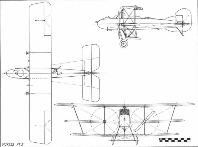
Vickers FT.2
<...>
In 1916 a single-seat fighter to take the Vickers-sponsored Hart radial engine was designed by R. K. Pierson. This was the F.B.16 tractor and was known as the Hart Scout. The Hart engine proved as disappointing as previous power units (such as the Boucier) sponsored by Vickers. After considerable redesign the type reappeared as the F.B.16A with a 150 hp Hispano Suiza, a French-designed water-cooled engine then coming into favour with the British air authorities. Later the more powerful 200 hp Hispano Suiza was substituted, and in this form the aeroplane became the F.B.16D. It earned the unqualified praise of Maj J. B. McCudden, the British air ace, of 56 Squadron, whose book on five years in the RFC remains the classic on air fighting and the technology thereof in the first world war. In this book he describes vividly, as follows, his experiences in flying the all-red F.B.16D at Joyce Green, where he was a constant visitor when on leave from France.
'On 22 June, 1917, I flew the little Vickers tractor, the F.B.16D, which was now fitted with a 200 hp Wolseley-Hispano. I climbed to 10,000 ft in eight minutes and at that height the machine did 136 mph. Whilst flying that machine I got some idea of the speed of future machines, for at 10,000 ft it was 30 mph faster at least than anything I had yet flown. Harold Barnwell liked this little machine, although he said it cost him a new pair of trousers every time he flew it, as it always smothered his legs with oil. It has a very deep fuselage rather out of proportion to the size of the machine and Barnwell always alluded to it as "Pot-Belly".'
McCudden was keen to take the F.B.16D with him to his Squadron in France, but it was not the policy to allow pilots, however distinguished, to have, at the Front, personal aircraft which differed from standard equipment. He therefore left the F.B.16D at Joyce Green when he returned to France, where he was killed in an accident to his S.E.5a before reaching his base.
The F.B.16D never went into production because large contracts had been placed for the contemporary S.E.5a, particularly with Vickers at Crayford and Weybridge, and because the engine in the Vickers fighter was inaccessible for servicing and maintenance in the field. But it embodied an unusual feature for a British aeroplane. A Lewis gun was installed between the vee formed by the cylinder blocks and fired through the hollow propeller-shaft which rotated through gearing above the engine crankshaft. How the ammunition drums were changed or whether a belt feed was substituted, or, indeed, how the empty cartridge cases were collected or jettisoned, remains unexplained.
A derivative of the type, the F.B.16E, was made, under licence by S. A. Darracq in France, with larger two-bay wings to cater for the extra weight of the 275 hp Lorraine-Dietrich engine, but it did not go into large-scale production there.
F.B.16D - One 200 hp Hispano Suiza. Span 25 ft, upper, and 22 ft 4 in, lower; length 19 ft 6 in; height 8 ft 9 in; wing area 207 sq ft. Empty weight 1,376 lb; gross weight 1,875lb. Max speed 135 mph at 10,000 ft; climb to 10,000 ft - 10 1/2 min; service ceiling 18,500 ft; absolute ceiling 21.000 ft; endurance 2 1/4 hr. Armament - two Lewis guns.
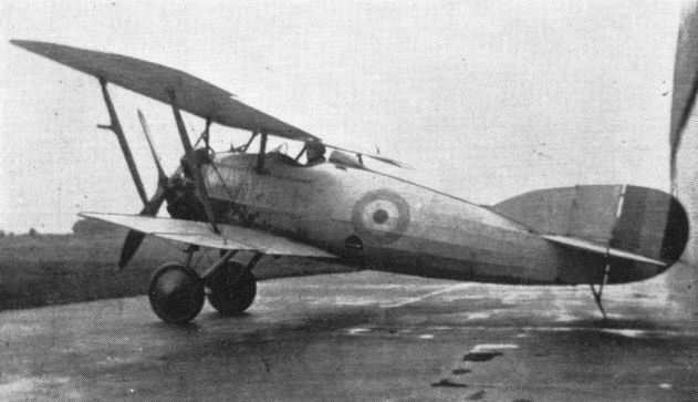
F.B.16 Hart Scout in its original form with the Hart radial engine.

F.B.16D - known to Barnwell as 'Pot Belly', and the favorite hack of the British ace McCudden.
Increased wing chord and more vertical tail area distinguished the F.B.16D.
Increased wing chord and more vertical tail area distinguished the F.B.16D.
A line-up of Vickers experimental aircraft at Joyce Green; (left to right) F.B.12C, F.B.14, F.B.11, F.B.16.
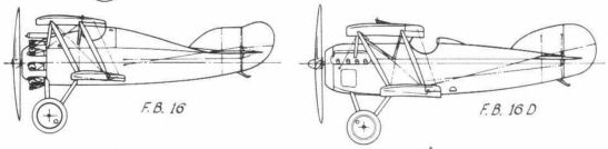
F.B.16, F.B.16D
<...>
A further development of the Bullet appeared in August 1916 as the F.B.19, in an unstaggered version as the Mk I and later in a staggered version, the Mk II. The former had either the 100 hp Gnome monosoupape or 110 hp Le Rhone and the latter the 110 hp Le Rhone or the 110 hp Clerget. About 50 Mk Is and 12 Mk lis were made at Weybridge and were used in small numbers on the Western Front, in Macedonia and Palestine. A demonstration Mk I was sent to Russia which led to a small batch of Mk IIs being sent to Archangel, but there they remained in their crates when the Revolution intervened, Russia withdrawing from the war, and are believed to have been destroyed by British Forces in 1919.
F.B.19 - Bullet Mk I - One 110 hp Le Rhone. Span 24 ft; length 18 ft 2 in; height 8 ft 3 in; wing area 215 sq ft. Empty weight 900 lb; gross weight 1,485 lb. Max speed 102 mph at 10,000 ft; climb to 10,000 ft - 14 min; service ceiling 15,000 ft; absolute ceiling 17,500 ft; endurance 2 3/4 hr. Armament one Vickers gun.
F.B.19 - Bullet Mk II - One 110 hp Clerget. Span 24 ft; length 18 ft 2 in; height 8 ft 3 in; wing area 215 sq ft. Empty weight 890 lb; gross weight 1,475 lb. Max speed 98 mph at 10,000 ft; climb to 10,000 ft-14 1/2 min; absolute ceiling 16,500 ft; endurance 3 hr. Armament one Vickers gun.

An F.B.19 Mk I at Brooklands, with Archie Knight (assistant instructor) on right.
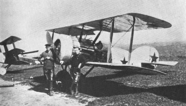
A Vickers F.B.19 Mk I in service with Soviet forces in company with a Sopwith Triplane.
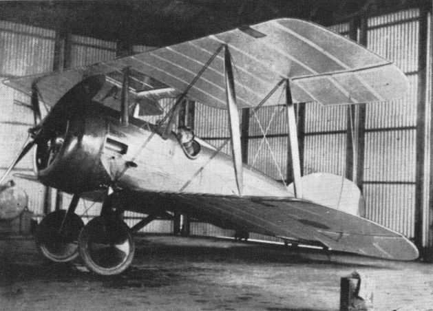
A Weybridge-built F.B.19 Mk II Bullet, 1917.

F.B.19 Mk II A5236 at Deir el Balah (now in the Gaza Strip).

F.B.19 Mk.II
<...>
The F.B.24 was a straightforward two-seat tractor biplane for fighter reconnaissance and comparative with the Bristol Fighter, designed by Capt Frank Barnwell, brother of Vickers' Harold Barnwell. It was yet another design intended for the ill-fated Hart engine and followed the familiar pattern in being fitted with a variety of makeshift power units. The prototype, designated F.B.24A, had the 200 hp Hispano Suiza, as did also the second airframe, the F.B.24B; the F.B.24C was fitted with the 275 hp Lorraine-Dietrich in the French works of S. A. Darracq while the F.B.24D had the 200 hp Hispano Suiza. In the F.B.24E the upper wing was attached directly to the top of the fuselage, to improve the view of the crew. The F.B.24G with the large 375 hp Lorraine was built by Darracq in France and did not fly until some time after the war; it used the wing and fuselage arrangement of the F.B.24E, but was an ungainly aeroplane.
F.B.24E - One 200hp Hispano Suiza. Span 35 ft 6 in, upper, and 30 ft, lower; length 26 ft; wing area 340 sq ft. Empty weight 1,630 lb; gross weight 2,610 lb. Max speed 122 mph at 5,000 ft; climb to 10,000 ft - 15 min; absolute ceiling 16,000 ft; endurance 3 hr. Armament one Vickers gun and one movable Lewis gun.
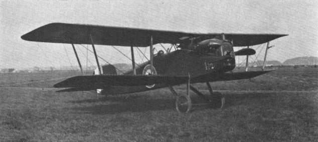
F.B.24C with Lorraine-Dietrich engine as built in France.

F.B.24E showing direct attachment of upper centre section to top longerons of fuselage - combat disposition of crew seems a problem, as this example was experimental, with the pilot in the rear seat.

F.B.24E showing direct attachment of upper centre section to top longerons of fuselage - combat disposition of crew seems a problem, as this example was experimental, with the pilot in the rear seat.
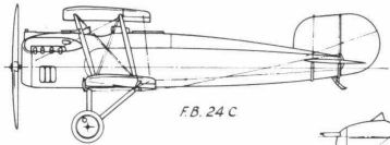
F.B.24C
<...>
A further development of the Gunbus was projected in the F.B.23 for a pusher fighter of 38-ft span as a replacement for the F.B.9. This failed to materialise, but an unusual development of this design to carry the Crayford rocket gun was built in Vickers' experimental shop at Gravel Hill, Bexleyheath. This was the F.B.25, and the power unit was the 150 hp Hispano Suiza. It was intended as a night-fighter to fill the same requirement as Farnborough's N.E.1, but it was crashed by a Service test pilot in May 1917, after an unflattering flight-test report.
F.B.25 - One 150 hp Hispano Suiza. Span 41 ft 6 in; length 28 ft 1 in; height 10 ft 10 in; wing area 500 sq ft. Empty weight 1,608 lb; gross weight 2,454 lb. Max speed 86 mph at 5,000 ft; climb to 10,000 ft - 27 1/4 min; service ceiling 11,500 ft; absolute ceiling 13,500 ft; endurance 4 1/2 hr. Armament one Vickers Crayford rocket gun.
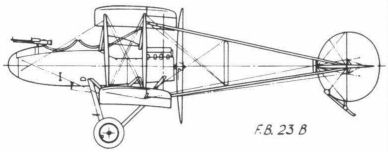
F.B.23B
<...>
Also in the single-seat fighter class were the two Vickers pusher types, the F.B.12 and the F.B.26. Both had chequered careers.
<...>
The later F.B.26 pusher was a more sophisticated design originally intended as a single-seat night-fighter, powered with a 200 hp Hispano-Suiza. During an evening test flight on 25 August, 1917, Harold Barnwell spun the prototype into the ground just after take-off at Joyce Green, almost at the feet of his devoted mechanic H. J. Kingsnorth, who had just started up the aeroplane and was the only close witness of the fatal accident. The cause of this tragedy with so able a pilot remains a mystery. Writing from New Zealand, whence he emigrated in 1919, Kingsnorth said that he never recovered from the death of his hero Harold Barnwell, who, terse of speech and bluff in manner, had played a great part in the early development of British aviation, as did his brother, Capt Frank Barnwell, of the Bristol Aeroplane Company.
Three modified F.B.26s were built, and under the then recently introduced official nomenclature were named Vampire. One was modified as the F.B.26A, and named Vampire Mk II, with an armoured nacelle for ground attack, power being provided by the 230 hp Bentley B.R.2 rotary engine. But the contracts that were placed for this specialist duty type went to the Sopwith Salamander, a tractor biplane. One of the F.B.26s was fitted with the Eeman three-gun universal mounting, designed to increase fire power, but this armament proved unwieldy in practice. The F.B.26A was probably the last of the single-seat pusher fighters of the first world war, but the design philosophy was revived years later in the Vickers COW gun fighter of 1931.
F.B.26 - Vampire Mk I - One 200 hp Hispano Suiza. Span 31 ft 6 in, upper, and 29 ft. lower; length 23 ft 5 in; height 9 ft 5 in; wing area 267 sq ft. Empty weight 1,470 lb; gross weight 2.030 lb. Max speed 121 mph at 5,000 ft; climb to 10,000 ft - 10 min; service ceiling 20,500 ft; absolute ceiling 22,500 ft; endurance 3 hr. Armament twin fixed Lewis guns.
F.B.26A - Vampire Mk II - One 230 hp Bentley B.R.2. Span 31 ft 6 in, upper, and 27 ft 6 in, lower; length 22 ft 11 in; height 9 ft 5 in; wing area 267 sq ft. Empty weight 1,870 lb; gross weight 2.438 lb. Max speed 121 mph at ground level; climb to 10,000 ft - 12 min; absolute ceiling 19,000 ft; endurance 2 hr. Armament twin fixed Lewis guns.

The prototype F.B.26 with Hispano Suiza engine at Joyce Green, 1917, showing close resemblance to the F.B.12.

The prototype F.B.26 with Hispano Suiza engine at Joyce Green, 1917, showing close resemblance to the F.B.12.
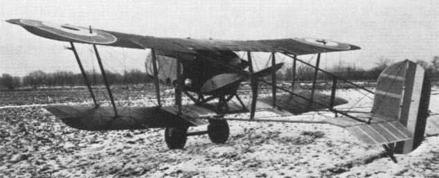
Rear view of one of the very few F.B.26 single-seat pusher fighters made, photographed in the winter of 1917/1918, the prototype having crashed in the previous August.
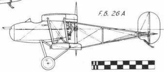
F.B.26A
The Vimy
The E.F.B.8, which appeared in November 1915, powered by two Gnome monosoupapes, was smaller than its predecessor and carried only a single light Lewis gun, which could be accommodated equally well in single-engined types. This redesign was entrusted to Pierson, who stored the knowledge gained and revived it when a new twin-engined bomber was called for from Vickers by the Air Board in 1917, in the following circumstances.
Capt Peter D. Acland, at the time assistant manager in the Aviation Department of Vickers, gave the following account, in 1944, of the inception of the Vimy:
'The initiation of the design of the Vimy by Rex Pierson was the result of a conversation I had with Alec Ogilvie (Holding a position corresponding later to the Director of Technical Development) at the old Hotel Cecil in July 1917. At the time a large number of Hispano engines was surplus to fighter requirements for which they (the Air Board) were seeking a use. At that same time they were not getting sufficient Rolls-Royce Eagles to fulfil all their bombing requirements, and it was suggested to me that Vickers should attempt to build a bomber around the Hispano engine to the same specification as the Handley Page O/400.
'Pierson rapidly produced general layout designs, and an immediate order for prototypes was given. The first of these was flown by Gordon Bell at Joyce Green on 30 November, 1917. There was a different type of engine fitted into each of the other prototypes, including B.H.P., Fiat, Salmson and, subsequently, the Rolls-Royce Eagle.
'When the time came to place the production orders in April 1918, the Rolls was decided upon. History tells us the rest. The designing, building and flying of the machine in a period of four months was, to my mind, one of the highest spots of co-operative effort I have come across in many years in the industry.'
Pierson had related this story in a broadcast talk in 1942, when he said that with Maj J. C. Buchanan of the Air Board (later Air Ministry) he drew up the outline of the proposed Vickers bomber on a piece of foolscap paper in the Hotel Cecil, the Board's headquarters.
The four F.B.27 prototypes were fitted with 200 hp geared Hispano Suizas (later re-engined with 260 hp Salmsons), 260 hp Sunbeam Maoris, 300 hp Fiat A-12 and 360 hp Rolls-Royce Eagle VIIIs. These prototypes were conveniently referred to as Marks I to IV, but surviving Weybridge drawings do not confirm this early nomenclature, and official evidence on the subject seems to be conflicting. The Mark number system was never received with much enthusiasm on the production side until recent history, when it came to mean a lot more than merely airframe or engine modifications.
In the first F.B.27, called Vimy when the official naming of aircraft was introduced in 1918, the Hispanos were changed to Salmsons; the second, with Maoris, was lost soon after trials began because of engine failure; and the third, with the Fiats, also was lost by stalling on take-off at Martlesham and blowing up in the resulting crash as its bombs were armed (presumably for live practice over the nearby Orfordness armament and bombing ranges). The fourth Vimy prototype, with Eagles, went to Martlesham on 11 October, 1918, and confirmed the impression of exceptional performance for the period earned by the original F.B.27 in the previous January, also under test at Martlesham, the then newly established Aeroplane Experimental Establishment (Later renamed Aeroplane and Armament Experimental Establishment).
The original Vimy, with its geared Hispanos of dubious reliability, had lifted a greater load than the much larger and more powerful Handley Page O/400. The Eagle-powered Vimy prototype had a speed of 100 mph and endurance of 11 hours with full crew and a load of nearly 5,000 lb (including fuel) out of a take-off weight of 12,500 lb, a remarkable achievement in its day.
Behind the scenes in official quarters a controversy had raged between the protagonists of tactical and strategic bombing. This seems to have been resolved because of the need to retaliate against the night bombing of targets in Britain by German aeroplanes, which began in September 1917. In consequence, the Vimy was one of the new heavy bombers selected for production. The first contract, for 150, received by Vickers was on 26 March, 1918, and was followed shortly afterwards by another for 200, the first batch to be made at Vickers' Crayford works and the second at Weybridge. With contracts to other firms, the order book reached 1,130, with variations as to the specified power units. Production during 1918 was to be reserved for aircraft for anti-submarine duties (carrying two torpedoes) and subsequent deliveries for night-bombing aircraft.
The urgency of combating the U-boat menace with a more devastating weapon than the Blackburn Kangaroo, then operating, probably dictated the priority for anti-submarine work, but no Vimy was in fact ever used in that role.
In October 1918 one Vimy bomber was flown to Nancy, in northeast France, to stand by for a series of long-range raids deep into Germany, including Berlin. The Armistice of 11 November, 1918, cancelled this plan, and consequently the Vimy was not used operationally in the first world war.
Following the cessation of hostilities, the Government drastically reduced all orders for military aircraft, including those for Vimys, after Crayford had made seven and Weybridge six, but subsequently Weybridge made 99 Vimys for the peacetime Royal Air Force. Components already completed were purchased from certain of the former outside contractors, which aided production, and special aircraft were modified from the military versions to undertake long-distance pioneering flights. Indeed, the first aeroplane to make a trans-oceanic flight non-stop was the now famous Vimy crewed by Capt Jack Alcock (Among his colleagues in the pioneering days of pre-1914 Brooklands, Alcock was known as 'Jack') and Lt Arthur Whitten-Brown on 14-15 June, 1919, across the Atlantic.
The production Vimy followed the conventional design trends of its time, having a wire-braced biplane wing structure and stabiliser, also of biplane form, with twin fins and rudders. The front fuselage was of steel tube and the rear fuselage was of wood with steel end-fittings and swaged tie-rod bracing. The rear longerons were hollow spars to the McGruer patent, devised by a Clyde yacht designer and consisting of wrapped shims machined circumferentially from spruce logs. Recently examined by the inventor, the longerons on the transatlantic Vimy now in the Science Museum in London were found to be in perfect condition. Rudders and ailerons were aerodynamically balanced by extensions forward of the hinge points. The whole design was well proportioned, and upon this factor depended its success. Its Rolls-Royce engines were admirably suited to it, which was a new experience as far as Vickers were concerned, for their designers had suffered miserably from the allocation of unsuitable engines for previous aircraft, as has already been emphasised.
The use of Vickers' own wind tunnel at St Albans, the first commercially owned example anywhere, helped considerably in predicting aerodynamic performance and configuration, and Pierson cleverly exploited the reduction in scale from contemporary designs (as represented by the Handley Page O/400) to reduce structure weight. He also introduced refinements in detail design to achieve maximum strength factors.
Provision was made in the fuselage for part of the bomb load, the rest being carried under the bottom planes, with simple release gear. Two gunners could be carried, one in the nose with a Lewis on a Scarff ring, another similarly armed aft of the wings, with provision for shifting the gun to a pivot mount on the bottom of the fuselage for firing aft under the tail, with side windows for light when changing ammunition drums.
Maximum range was 1,880 miles, and the Vimy was easily capable of carrying what was for its time quite a respectable bomb load to Berlin. Various figures of speed have been quoted, from 98 mph to the 112 mph which Capt Broome, a Vickers pilot, was able to record on one test flight. Climb to 6,000 ft took 18 minutes, and the Vimy's ceiling, when fully loaded, was not more than 12,000 ft. Within this performance envelope, Alcock and Brown had to fly through the weather across the Atlantic. This led them into icing troubles and flying attitudes of the most unfamiliar character, in weather conditions which today's high-flying airliners can usually avoid.
The Ross and Keith Smith brothers' flight to Australia at the end of 1919 in a specially prepared Vimy proved the soundness of the design from another angle. It showed that the aeroplanes of the time could be operated across continents to far distant places and foreshadowed the day when scheduled services would be operated between Europe, the Far East and Australia, just as Alcock and Brown had presaged regular Atlantic air routes. The attempts to reach Cape Town by air by the Vimy of Van Ryneveld and Quintin Brand, and the other, sponsored by The Times and flown by Vickers' test pilots, Cockerell and Broome, did not experience complete success. But a far-reaching discovery had been made. Technical progress was needed to overcome the combined effect of high operating temperatures and greater altitudes on engine behaviour and performance, and on improvements in airframes, for wood and fabric and tropical conditions did not agree with one another.
Although the three pioneering flights undertaken by Vimys soon after the first world war have been fully documented, including a book (The Flight of Alcock and Brown, Graham Wallace (Putnam)) on Alcock and Brown's Atlantic conquest, the essential details are included here to keep the record complete.
For the Atlantic flight all the military equipment was removed from a standard Vimy (The 13th airframe off the post-war production line at Weybridge) and extra tankage installed in its place, thus increasing the fuel capacity from 516 to 865 gallons to give an optimum range of 2,440 miles. Actually, enough fuel for another 800 miles remained in the tanks after the flight had terminated in the Derrygimla bog at Clifden, County Galway, for the prevailing westerly wind had been of some assistance, as is normal in scheduled operations today. The engines were the standard Rolls-Royce Eagle VIIIs of 360 hp each, and they functioned reliably except for an occasional icing-up of the air intakes. In the twin-engined configuration it was possible for the crew to see the radiators and air intakes; with a single-engined tractor aeroplane this was not possible, and one theory now advanced for the failure of Hawker to complete the Atlantic flight on the Sopwith single-engined tractor machine was that his radiator shutters were partially closed through a control maladjustment, thus causing the engine temperature to rise. Had he been able to see his engine, this would not have occurred, and some weight is lent to this conjecture by the fact that the Sopwith also had the Rolls-Royce Eagle VIII engine, the type which did so well in the Vimy.
From take-off near St John's, Newfoundland, to landing in Ireland, the Vimy took 16 hr 27 min on the 1,890 mile non-stop flight, which included the night of 14 June. Visibility was too poor most of the time for the navigator to take sights and the weather anything but good for such an adventure virtually into the unknown. Their objective was Galway Bay, the conditions of the Daily Mail ?10,000 prize having specified 'anywhere in the British Isles' as the terminating point. Whitten-Brown, with his improved nautical methods of navigation, devised while he was a prisoner of war, crossed the Irish coast at Clifden, only a few miles north of his flight plan.
The Vimy was partially wrecked on landing in the bog; had the two airmen but known, the green pasture next to the one they had selected was quite solid, according to eye-witnesses at the time. The omission of the nosewheel in Newfoundland to reduce drag and weight was probably a sound idea, but that wheel might have saved the aircraft from nosing into the bog. The Vimy was rebuilt at Weybridge after recovery, and now is a treasured exhibit in the Science Museum in London, where one can engage in an interesting exercise in comparing it with modern aircraft, particularly with regard to its primitive navigational aids, and to its structure, now partially exposed to public view.
The next major event which was to concern the Vimy was the offer of a prize of ?A10,000 by the Australian Government for the first flight by Australians from Britain to Australia, to be completed within 30 days and before the end of the year 1919. Maxwell-Muller had engineered the Vimy at Weybridge for the Atlantic flight and prepared another for this fresh challenge. It was more or less of the standard military type with few changes apart from the provision of additional stores, to cope with tropical flying, in place of the normal military load.
The pilots chosen were the Smith brothers, Ross and Keith, of the Australian Air Force, as were the two mechanics, Sgts W. H. Shiers and J. M. Bennett. A considerable amount of pre-flight planning had to be done, petrol, oil and essential stores laid down at strategic points en route, and landing grounds carefully surveyed by agents in advance.
As far as Calcutta the air route was fairly well known, but eastwards from there the flight took on the form of trail blazing. The Vimy, valiantly flown and serviced by its Australian crew, won through, like Sir Francis Drake, 'after many vicissitudes', including vile weather, and reached Darwin from Hounslow in just under 28 days on 10 December, 1919, having covered 11,130 miles in 135 hr 55 min elapsed flying time. The aeroplane, G-EAOU, is now preserved in a memorial hall on the airport at Adelaide, home of the pilots, for the building of which the Australian public subscribed some ?A30,000.
The third great flight attempted by the Vimy was for a flight from England to Cape Town. Several efforts were made, but two Vimys achieved the greatest success. One was a standard military type, called the Silver Queen, flown by Lt-Col Pierre Van Ryneveld and Maj C. J. Quintin Brand of the South African Air Force. They left Brooklands on 4 February, 1920, but crashed at Korosko between Cairo and Khartoum a week later, a mishap caused by a leaking radiator. A second Vimy was loaned by the Royal Air Force in Egypt and named Silver Queen II. This one reached Bulawayo in Southern Rhodesia. There it failed to lift off from the high-altitude aerodrome in high temperature with a failing engine, caused by dirty oil, and was put out of action. The crew borrowed a D.H.9, completed the flight to Cape Town and were awarded ?5,000 each by the South African Government. They were knighted by King George V, as were the Smith brothers and Alcock and Brown, after their respective efforts.
Height and heat also defeated the other attempt by a Vimy, chartered from Vickers by The Times, with Dr Chalmers Mitchell as their Press representative on the flight. The aeroplane was the prototype Vimy Commercial G-EAAV (originally K-107). It left Brooklands on 24 January, 1920, and crashed at Tabora, Tanganyika, on 27 February, failing to takeoff in tropical conditions. It was found that the water in the cooling system of one of the engines was contaminated. It was clear that further engine and airframe development would be needed to operate in such conditions if the lessons of these African flights were to be fully applied. Judging from the successful use of the Vimy and its family successors in Egypt, the Middle East and India in later years, it seems clear that these troubles in African flying were taken to heart.
No. 58 Squadron RAF, in Egypt in July 1919, was the first to receive the Vimy bomber, as the Handley Page O/400 replacement, and operated the Vickers type until disbanded in February 1920. Subsequently, the type equipped other Middle East squadrons, and No. 216, with Vimys, ran some of the first mail services between Cairo and Baghdad. No. 7 Squadron at Bircham Newton was equipped with Vimys in June 1923, although 'D' Flight of 100 (the nucleus of 7 Squadron), had previously operated them at Spittlegate. Nos. 9 and 58 home-based Squadrons received Vimys in April 1924, on the re-forming of those units.
After replacement by the larger and more powerful Virginias in 1924 and 1925, the Vimy remained in service with 502 Squadron at Aldergrove, Northern Ireland, until 1929. Subsequent to their withdrawal from firstline service as standard heavy bombers, Vimys were re-engined with aircooled radials, either Bristol Jupiters or Armstrong Siddeley Jaguars, in place of the water-cooled Rolls-Royce Eagles. These were used in flying training schools such as No. 4 F.T.S. at Abu Sueir, Egypt, and for parachute training at Henlow. From Biggin Hill a night-flying unit equipped with Vimys operated long after the type had disappeared from the rest of the Royal Air Force; in fact, the Vimy was used right up to the time of the Munich crisis in 1938 as target aircraft for the searchlight crews of the Royal Engineers training at Blackdown, Hants.
Vimy (F.B.27) Vimy Mk II (F.B.27A)
Accommodation: Pilot and 2 gunners Pilot and 2 gunners
Engines: Two 200 hp Two 360 hp
Hispano-Suiza Rolls-Royce Eagle VIII
Span: 67 ft 2 in 68 ft
Length: 43 ft 6 1/2 in 43 ft 6 1/2 in
Height: 15 ft 3 in 15 ft 7 1/2 in
Wing Area: 1,326 sq ft 1,330 sq ft
Empty Weight: 5,420 lb 7,101 lb
Gross Weight: 9,120 lb 12,500lb
Max Speed: 87 mph at 5,000 ft 103 mph at ground level
Climb to 5,000 ft: 23.5 min 22 min
Service Ceiling: 6,500 ft 7,000 ft
Absolute Ceiling: 9.500 ft 10,500 ft
Endurance: 3 1/2 hr 11 hr
Armament: Two Lewis guns Two Lewis guns
Eighteen 112-lb 2,476-lb bomb load
and two 230-lb bombs

A Vimy under construction at Crayford
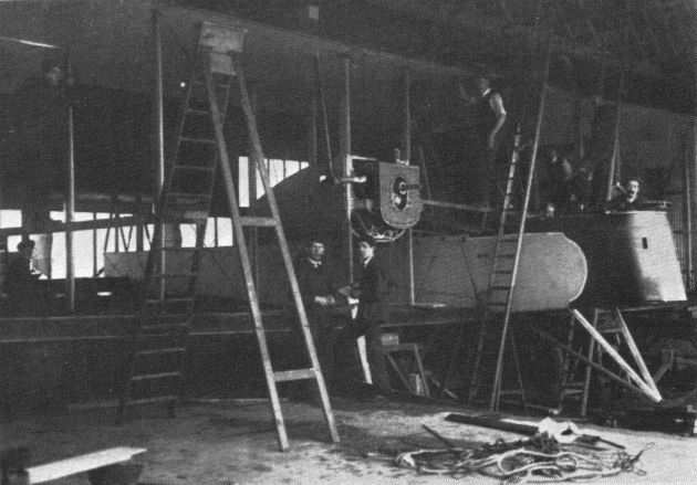
Prototype F.B.27 Vimy under final erection at Joyce Green in 1917; for the roll-out the floor of the hangar had to be recessed to provide height clearance for the completed aeroplane.
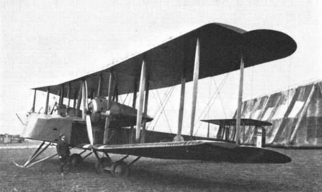
Prototype B9952 as re-engined with Salmson water-cooled radial engines.
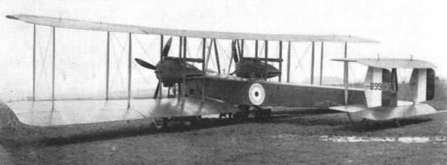
Second prototype Vimy, B9953, with Sunbeam Maori engines, which was written off through an engine failure on flight trials.
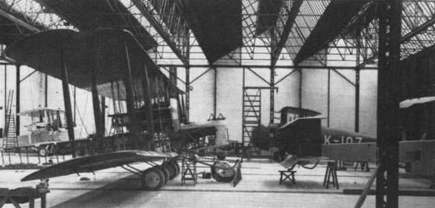
A view inside Weybridge new erecting shop early in 1919 showing Vimy bombers under construction, and in the background, on the right, the prototype Vimy Commercial, on the left, the Transatlantic Vimy, less outer planes.

The Transatlantic Vimy being erected at Quidi Vidi airfield, near St John's, Newfoundland - later it was flown to Lester's Field for take-off.

The Transatlantic Vimy being erected at Quidi Vidi airfield, near St John's, Newfoundland - later it was flown to Lester's Field for take-off.
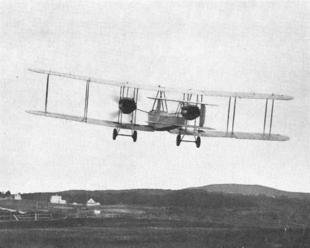
Take-off of Alcock and Brown in Vimy for the first direct Atlantic flight, 14 June, 1919; photographer was H. J. Holloway of St John's, and the copyright was afterwards acquired by Vickers.
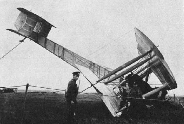
End of first direct Atlantic flight in the Derrygimla bog, Clifden, Co. Galway, Ireland, on 15 June, 1919.
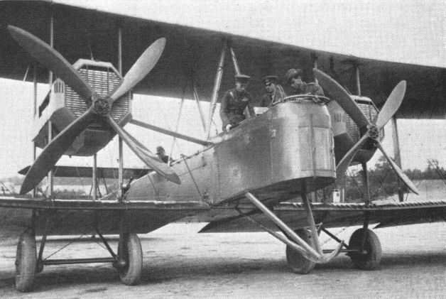
Crew inspection of Vimy bomber selected for the England-Australia flight - in front, left to right Capt Ross Smith, Lt Keith Smith and Sgt W. H. Shiers; in rear cockpit, Sgt J. M. Bennett.

Take-off of Vimy for Australia on 12 November, 1919, from the old Hounslow airfield, the site of which was about two miles east of the present London Airport, Heathrow.

Australian Vimy G-EAOU running engines at Hounslow before departure for Australia.
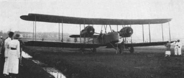
Australian Vimy G-EAOU running engines on Singapore racecourse preparatory to resuming flight.

The Vimy left for Australia on 12 November, 1919, from the old Hounslow airfield, the site of which was about two miles east of the present London Airport, Heathrow.

The replica Vickers Vimy built by the Vintage Aircraft and Flying Association to commemorate the 50th anniversary of the first nonstop North Atlantic flight in June 191. G-AWAU first flew on 3 June, 1969. It was repainted as H651 and damaged by fire at Manchester Airport. Repaired, the Vimy is now in the Royal Air Force Museum, Hendon, as F8614.

The replica Vimy as H651. The name on the nose is Triple First.
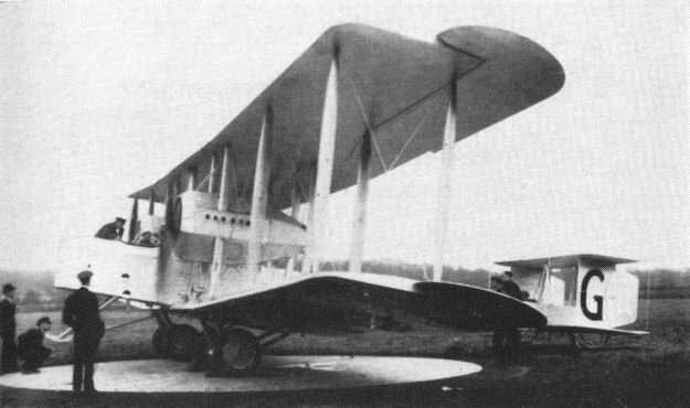
Vimy G-UABA Silver Queen on the compass base at Brooklands, being inspected by Van Ryneveld and Quintin Brand before their attempt to fly to Cape Town.
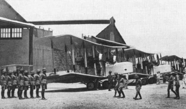
AOC's inspection of 4 FTS equipped with Vimy trainers at Abu Sueir, Egypt, 1930.
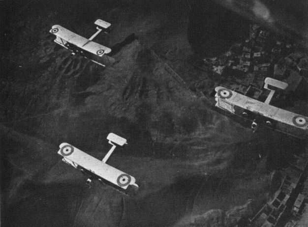
Vic flight of Vimy bombers somewhere in Egypt.
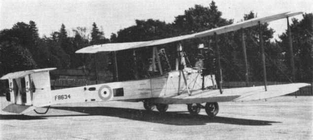
A Vimy of an early Weybridge batch converted there as a Jupiter-engined trainer.
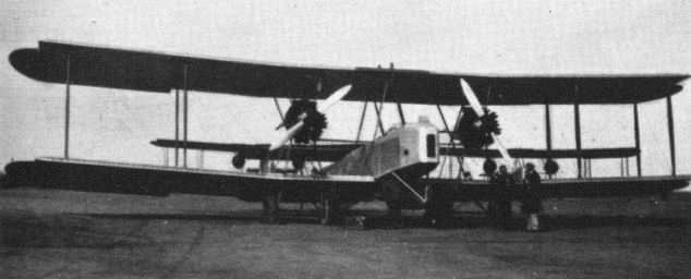
A Jaguar-engined Vimy trainer at Abu Sueir.
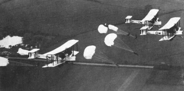
Jupiter-engined Vimys of the RAF Parachute Training School, Henlow.
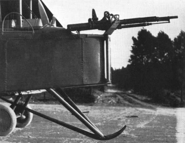
Coventry Ordnance Works one-pounder gun mounted on a Vimy bomber - the complete installation was in adaptable kit form.
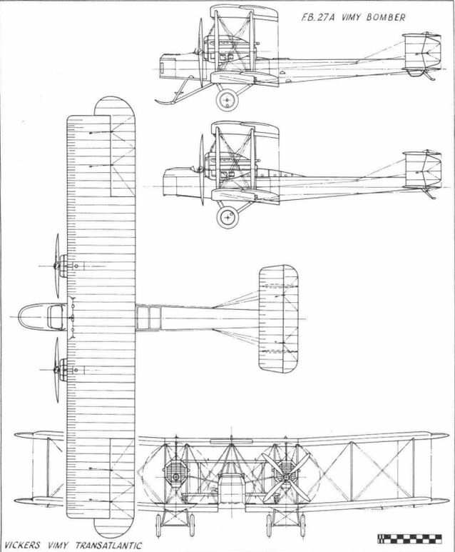
Vickers Vimy Transatlantic
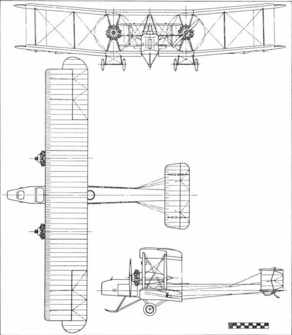
Vickers Vimy Jupiter Trainer
The Viking Amphibian
In December 1918 a project design was drawn up by Pierson for an amphibian flying-boat, to have its engine mounted above the hull deck under the centre section of the top wing. In order to provide crew and passenger accommodation forwards a pusher propeller was essential. This had to be of restricted diameter for hull clearance and, consequently, with wide blades to absorb the power.
To ease production in a class of aeroplane not previously built by Vickers (although they had the experience of S. E. Saunders and Co of Cowes, Isle of Wight, then Vickers' subsidiary, to rely on) and to provide a simple manually retracting land undercarriage, a hull with almost vertical sides was decided upon. This resulted in a narrow-beam planing bottom, as contrasted with the wider beam featured in the Linton Hope type of hull with sponsons, a design successfully exploited by the Supermarine Aviation Company, then a competitor of Vickers in this class. This narrow beam led to a measure of hydrodynamic instability, and various changes were made in the hull design to improve water-planing efficiency, through the various marks of Viking. Only in the last versions, named Vulture and Vanellus, was any serious attempt made to flare the sides of the hull to provide a wider planing bottom. The report of Vickers' water test-tank at St Albans, established in 1912 for testing ship models, disclosed a tendency of the Viking to porpoise, a phenomenon caused by the crests of the waves, formed by the front step, striking the chine aft.
The Viking prototype, the Mk I, was built in two months in a Weybridge dance hall, which had been used during the first world war by Vickers as a woodworking shop, and was completed at Brooklands. Female labour was principally employed. The aircraft flew at Brooklands in landplane form in late 1919 and was registered as G-EAOV.
Construction was conventional, with spruce wing members and elm timbers in the hull, which was covered with the patent Saunders Consuta copper-wire sewn plywood. A neat cabin was provided, with dual wheel control, and seats for four passengers. Pierson had studied a Norman Thompson NT2B single-engined flying-boat, exhibited in Harrods of Knightsbridge as a civil aeroplane, and fitted with a cabin. The Vickers design office was then (1918) located at Imperial Court, Basil Street, close to Harrods.
Late in the design stage some difficulty was encountered in choosing a suitable engine. After considering the 200 hp Wolseley-built geared Hispano Suiza, Pierson eventually decided to fit the 275 hp Rolls-Royce Falcon. Apparently one of the problems of the Hispano Suiza was how to embody a satisfactory air intake in a pusher arrangement, although earlier series of the same engine had been installed in the Vickers F.B.26 and the Royal Aircraft Factory's F.E.9 and N.E.I, all pusher propeller aircraft. The greater power of the Falcon was also desirable, and in subsequent marks further increases of engine power were found necessary; the Viking in its earlier versions was underpowered.
On 18 December, 1919, Sir John Alcock, then Vickers' chief pilot, was flying the Viking I, G-EAOV, solo to the Paris Aero Show when he ran into thick fog near Rouen, and in attempting a forced landing he struck a tree in an orchard. The aeroplane was wrecked and Sir John was killed, only a few months after he and Whitten-Brown had created air history by flying across the Atlantic. It was a premature ending to a brilliant flying career which began in the pioneering days at Brooklands aerodrome.
The Mk II Viking appeared later in 1919 and contained a number of modifications. It was powered by a Rolls-Royce Eagle VIII of 360 hp, mounted independently of the wing structure on a pylon mounting. The wheelbase was widened and undercarriage details improved, with increased-diameter wheels, and the wing area was increased and a third rudder added behind the central fixed fin. To overcome the tendency of the prototype to dig its bows into the water during take-off the nose of the Mk II was made more blunt. The re-entrant curve of the planing bottom between the steps was modified to try to solve the wave crest problem, and behind the rear step an oleo-pneumatic tailskid cum water-rudder was fitted. Stan Cockerell, who had taken the place of Sir John Alcock as chief pilot (later joined by Capt Broome), flew the Viking II, registered G-EASC, at Cowes in June 1920, and it was displayed at the Aero Show in Olympia that year. In August it won the Antwerp Seaplane Trials.
As a result of Cockerell's report, further modifications were made in the Viking Mk III, which was entered for the Air Ministry Competitions for civil aircraft held at Martlesham Heath and Felixstowe in September and October 1920. Registered G-EAUK, the Viking III won the competition for amphibians and the first prize of ?10,000. The Supermarine entry was such a close runner-up that the second prize was increased from ?5,000 to ?8,000. (Later on, in 1928, Vickers acquired the Supermarine Aviation Company.) In the official report of the Competitions was a suggestion that the tendency of the Viking to porpoise might be cured by altering the position or shape of the step, and also that the shape of the bows should be modified to keep down spray and sea. Flown by Cockerell, the performance of the Viking III was assessed as very good, and the judges were obviously impressed with the safety of the boat type of amphibian.
The main differences between the Mks II and III were the fitting of a still more powerful engine, the 450 hp Napier Lion, the lengthening of the nose while retaining the same shape of bows, a redesigned tailskid cum water-rudder, a further increase in wing area by introducing a slightly wider chord and, to counter greater engine torque, a small rectangular fin was added above the upper tailplane.
On 6 February, 1921, Cockerell began a series of tests with G-EAUK to determine the feasibility of passenger services from the River Thames, in the heart of London, to the River Seine, in Paris. These journeys took only two and a half hours, which bears comparison with elapsed times between the city centres of the two capitals today. Sir Frederick Sykes, Controller of Civil Aviation in Britain, and M. Laurent Eynac, his French opposite number, tested the service for themselves in April 1921. Subsequently, the Viking III went for trials on the aircraft carrier HMS Argus for which it was allocated the service number N147. The deck-handling and operating trials were quite satisfactory, the aeroplane taking-off easily and landing with no external aids except the deck-arrester wires.
As a result of these successful tests, covering a wide range of operational use both off the water and from land aerodromes, firm interest was created, and a production line was started at Weybridge of the Viking Mk IV in three main variants: fleet spotter, military and commercial. Some were fitted with folding wings, notably the fleet-spotter variants, where stowage space was a limiting factor.
The production Viking Mk IVs embodied further improvements from their experimental predecessors. The nose was made even more blunt, the beam of the hull was increased by one foot and the rear step was moved back also by one foot. The wheels were fitted with brakes and the tailskid cum water-rudder assembly again modified. The span was increased by 4 ft to 50 ft overall, and the loaded weight went up from the 4,500 lb of the Mk III to nearly 6,000 lb. Some Mk IVs retained the 46-ft span.
To promote quick take-off from restricted water areas a new high-lift wing-section, the T64, was made optional, in place of the Royal Aircraft Factory 15 standard wing-section. This new high-lift section had been developed from propeller design and had a flat undersurface similar to that later known as Clark Y. It had one drawback, a vicious tip stall. This, combined with the couple caused by the high thrust-line and the low drag component of the hull, made the Viking IV with the T64 wing-section a specialist type to fly. With the engine on, it was nose heavy; with the engine off, it was tail heavy. To inexperienced pilots, especially those accustomed to landplanes, the Viking presented quite a problem in avoiding the flat spin which was the bugbear of aircraft of comparatively slow speed. In addition, handling on or near the water in halation approach conditions on a mirror surface sea was then a little-practised technique (when actual height and horizon were difficult for positional assessment by the pilot).
In spite of all these difficulties, the Viking in production form rendered good service throughout the world in greatly differing operating conditions. Twenty-six examples of the Mk IV were sold. The first was the Vickers Type 54 for the French Navy, a commercial version with enclosed cabin but with provision for conversion for military duties 'with minimum of inconvenience', to quote the contract. It bore the French registration F-ADBL and was delivered on 27 September, 1921.
During 1922 the Viking production line was busy with orders for the Dutch Forces in the East Indies (10), the Imperial Japanese Navy (2), the Russian Trade Delegation (1) and Laurentide Air Services (Canada) (1). One was used for demonstration in Spain and registered G-EBED. It was subsequently sold to Capt Leslie Hamilton, who used it on charter to Capt Lowenstein, and also as an air taxi operating from the St Moritz winter sports centre in Switzerland, where it landed in soft snow on the hull and took-off from hard snow or ice with the wheeled undercarriage.
The Dutch Vikings were non-folders with Raf 15 section wings and Consuta-covered hulls. High-compression Napier Lion engines were fitted which ran on a benzol mixture, but reports indicate that some difficulty was experienced in starting, from which peculiarity German high-compression aero engines had also suffered. This was a matter for experienced ground engineering, while the sensitive fore-and-aft trim was a matter for experienced piloting. One of the two crashes of Vikings in Java was attributable to the fact that the pilot had never flown a flying-boat, while the other was caused by faulty maintenance in tropical sea conditions resulting in loss of rigging efficiency in the airframe and corrosion in the metal fittings. With long-range tanks, the range of the Dutch Vikings could be increased to 925 miles.
The Japanese Vikings were test flown by Maj H. G. Brackley off the carrier Hosho in March 1933 on acceptance trials. They were ordered as fleet spotters with T64-section wings, but the proposal to fit a 37-mm cannon for anti-submarine patrol was not proceeded with. In this connection both the Swedish and Italian navies considered slinging an 18-in-diameter torpedo aboard the Viking, but this proposal also was not pressed to a decision or an order. The Laurentide Viking for Canada was fitted with a Rolls-Royce Eagle IX and was rather underpowered. It was used for most of its time in Eastern Canada.
The Viking IV for the USSR was delivered in September 1922 and on arrival was sent for service in the Leningrad region. It was one of the first with a hull planked in SCT plywood made by the Tucker Armoured Plywood Company of Crayford. The initials SCT stood for 'securely cemented together', and the material consisted of two layers of Honduras mahogany board glued diagonally at right angles to each other; whether this produced any technical advantage over the Consuta planking does not seem to have been recorded. G-EBED, the Viking IV bought by Leslie Hamilton, also had the SCT-planked hull and wing-tip floats.
A special Viking IV registered G-EBBZ was prepared for Sir Ross Smith, commander of the Australian Vimy flight of late 1919, for a round-the-world attempt in 1922. It was a non-folder of the commercial version but with open cockpits. Various detail modifications were made, including some non-corrosive fittings, such as stainless-steel exhaust manifolds, and passenger space was taken up by stores and long-range tanks. After a preliminary test flight by Cockerell, at Brooklands on 13 April, Sir Ross Smith, with his mechanic of the Australian flight, Sgt Bennett, himself took the Viking up. At about 2,000 ft he stalled during a sharp turn and a fiat spin developed. Ross Smith opened the engine up and this action seemed to correct the spin. The engine was again shut down and the spin restarted at too low a height to be corrected a second time. The aeroplane crashed into the back of the Byfleet banking of the motor track near the River Wey and both occupants were killed. Sir Keith Smith, who had been delayed on his train journey from London and had intended to participate in the flight with his brother, was an eye-witness of the accident. The cause was thought to be the pilot's unfamiliarity with the aeroplane, particularly in regard to the engine on/off condition, and the tendency of the T64-section wing to tip stall.
Further orders for Viking IVs were received in 1923. This type of aeroplane seems to have been one of the first, certainly of Vickers design, to which the practice now called custom-built was applied. For example, one fleet spotter, ordered for the United States Navy in 1922 and delivered in February 1923, had the T64 wing section with the original span wing of 46 ft. A Lion engine was fitted in the American Viking, but the two Vikings delivered a week later to the River Plate Aviation Company, Argentina, were powered with the Rolls-Royce Eagle IX and were of the commercial type, with 50-ft span wings and the gap between the upper and lower wings increased by one foot, as well as having the Raf 15 wing section. One had an enclosed cabin and the other had open cockpits; both were fitted with large service fuel tanks mounted on the top wings. These two Argentine Vikings operated a regular service between Buenos Aires and Montevideo, and the service was so popular that it was difficult for intending passengers to get a seat. A high load factor was therefore obtained, but in spite of this the service had to be subsidised, and eventually the Vikings were withdrawn when financial support from the Argentine Government was cancelled. The only criticisms of the aircraft were that take-off was difficult in calm water conditions and that the wheels and tyres did not stand up to heavy duty. The Viking IV was undoubtedly underpowered with the 360 hp Eagle when loaded to nearly 6,000 lb.
The four Vikings delivered to the Argentine Navy in May 1923 were Lion-powered with full-span T64-section folding wings and were serialled R3, R4, R5 and R6. At the same time the Royal Canadian Air Force took delivery of two Viking IVs with Rolls-Royce Eagles, mainly to be used for starting a forestry fire patrol service and for survey work. Skis were fitted during winter operation. A proposal to fit Leitner-Watts metal propellers to these Vikings was not pursued. As a result of the successful introduction of Vikings for special service in Canada, a batch was made at the Canadian Vickers works in Montreal, and further specialist designs emanated from that source in their own right (see page 489). Canadian Vickers thus became one of the pioneer organisations in aircraft manufacture in Canada.
Two other Vikings were delivered in April 1922. These were to an Air Ministry requirement but with the special equipment used in RAF operation, and to comply with conditions laid down in the specification they were classified as Mk Vs. They were given the serial numbers N156 and N157, and were attached to 70 Squadron in Iraq, more or less in an exploratory exercise to determine the utility of amphibian aircraft in areas like the Middle East. Several discoveries were made. One was the frailty of aero wheels and tyres at that time in tropical conditions, although the RAF Viking Vs had oleo-sprung undercarriages, an innovation in the Viking amphibian. A hulled aeroplane with its short undercarriage was found difficult to operate off irregular desert surfaces because of insufficient clearance between the bottom of the hull and the ground, a penalty imposed by the amphibian configuration. In spite of these limitations, the Viking Vs fulfilled their purpose in adding to the experience being built up by the engineering branch of the Royal Air Force overseas. Particularly there was an awareness of the need for metal-framed aeroplanes to avoid loss of rigging truth inherent in wooden aircraft operating under tropical conditions, a factor encountered already with other Vickers wooden aircraft.
The Viking never seemed to suffer unduly from water soakage in its wooden hull, probably because on the average it spent half its life out of the water, thus allowing the intake of moisture to dry out. This was an unsuspected bonus of the amphibian configuration as compared with the wooden-hulled sea-going flying-boat operated only from marine bases. The design fully justified the ideas which had led to the formation of the original project. Its varied service in many parts of the world was a vindication of its name, Viking.
Viking Amphibian
Mk I Mk III Mk IV Mk IV
(G-EAOV) (G-EAUK) Type 55 Type 69
Engine: One 270 hp One 450 hp One 450 hp One 360 hp
Rolls-Royce Napier Lion Napier Lion Rolls-Royce
Falcon III Eagle IX
Span: 37 ft 46 ft 50 ft 50 ft
Length: 30 ft 32 ft 34 ft 2 in 34 ft
Height: 13 ft 13 ft 14 ft 14 ft 2 in
Wing Area: 368 sq ft 585 sq ft 635 sq ft 635 sq ft
Empty Weight: 2,030 lb 2,740 lb 4,040 lb 4,020 lb
Gross Weight: 3,600 lb 4,545 lb 5,790 lb 5,650 lb
Max Speed at sea level: 104 mph 110 mph 113 mph 100 mph
Climb to: 6,000 ft/12 min 6,000 ft/5.2 min 3,000 ft/3.2 min 5,000 ft/15 min
Range: 340 miles 420 miles 925 miles with -
at 85 mph at 90 mph long-range tanks
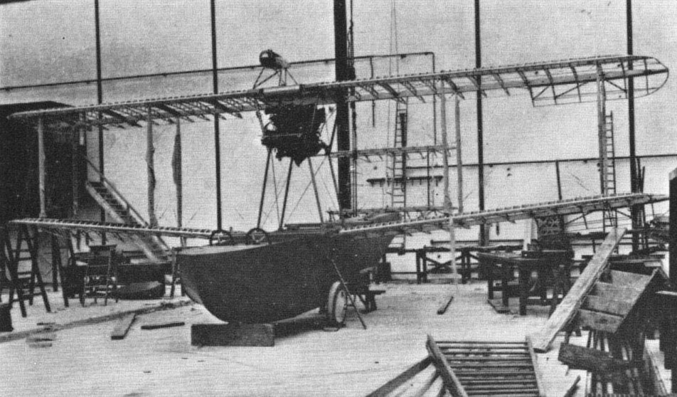
Prototype Viking amphibian in course of construction at Weybridge.
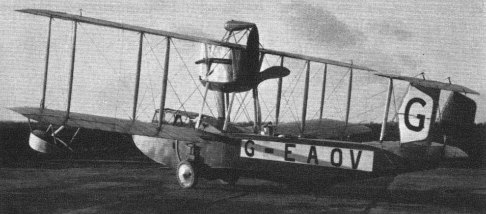
Prototype Viking amphibian, G-EAOV, in readiness for a test flight at Brooklands.

Prototype Viking amphibian, G-EAOV, at Brooklands.
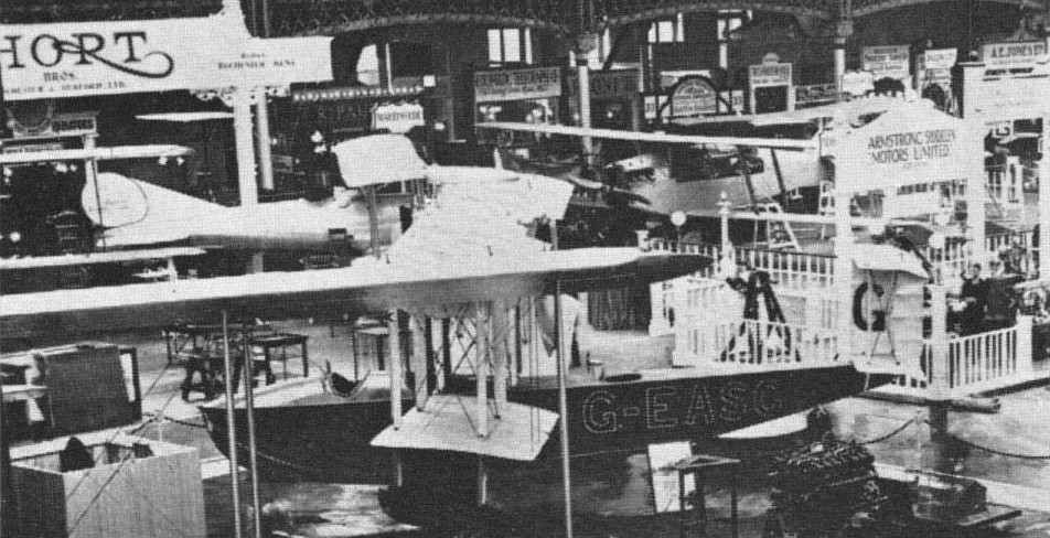
Viking II G-EASC at the Aero Show, Olympia, in 1920 behind wings of Vimy Commercial. At the rear is the Short Silver Streak and on the right the Martinsyde Type A Mk II civil transport.

Viking III G-EAUK
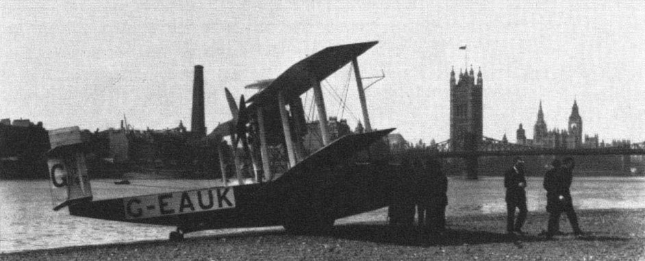
G-EAUK Mk III Viking during London-Paris centre-to-centre flights in 1921.
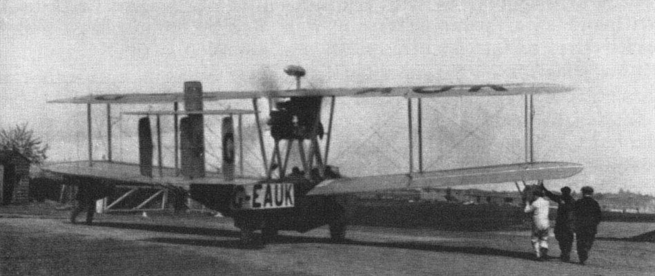
Viking III taxying across Woodbridge-Felixstowe road at Martlesham for Air Ministry Competition, 1920.
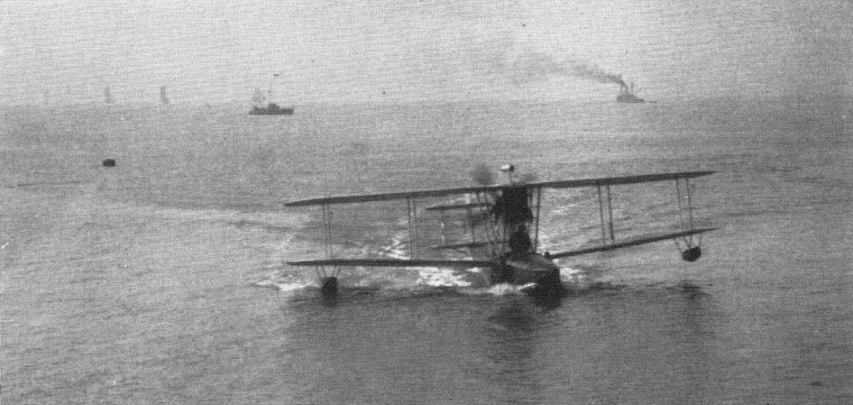
Viking III taxying at Felixstowe during Air Ministry Competition, 1920, in which it won first prize for amphibians.
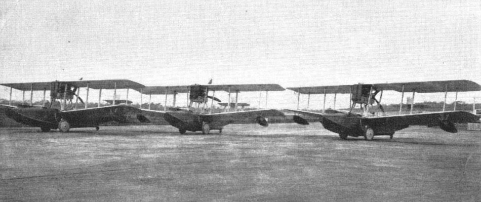
First production Viking amphibians; in centre Type 54 French order, and on outside, Dutch East Indies Type 55s with extended wing span.
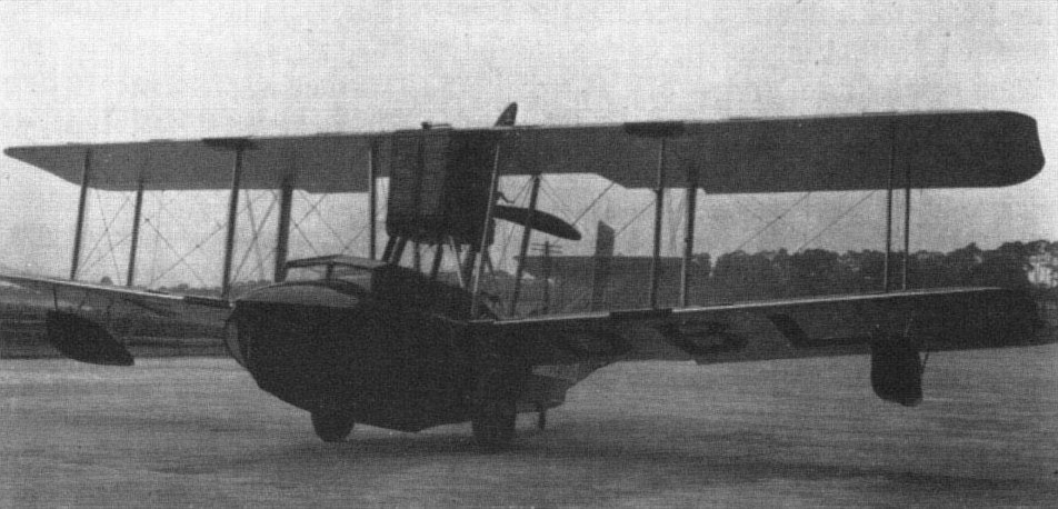
Type 54 Viking F-ADBL as completed for delivery with cabin.

Type 54 Viking F-ADBL as completed for delivery with cabin

Leslie Hamilton's Viking IV G-EBED at San Sebastian en route from Brooklands to Madrid.
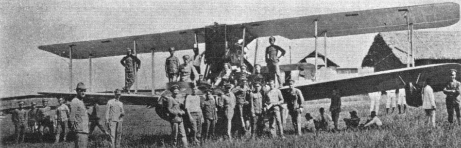
A Dutch Viking in Java.
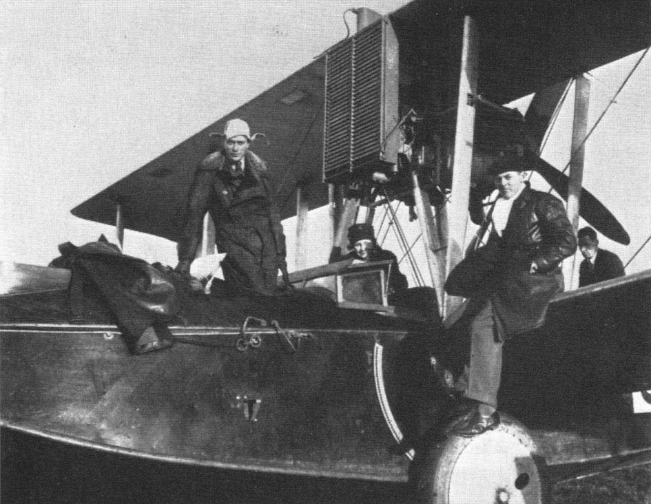
Leslie Hamilton's G-EBED, showing diagonal planking of hull and undercarriage-retracting rack quadrant.
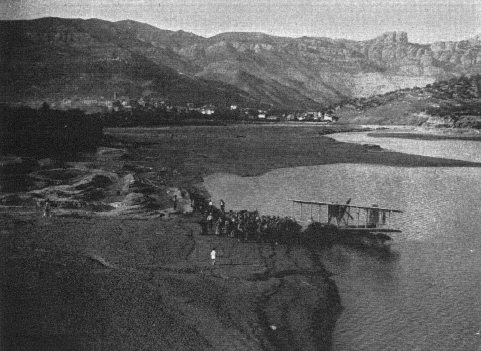
Leslie Hamilton's Viking at Pobla, Spain.

Only photograph of Ross Smith's round-the-world Viking, in erecting shop at Weybridge.
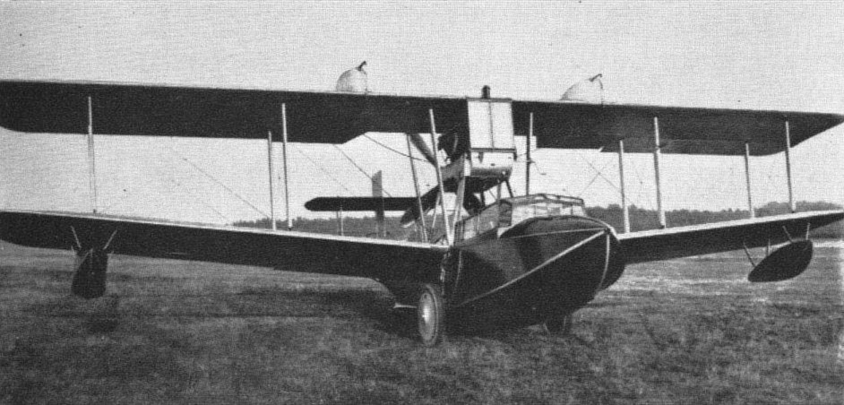
A civil cabin Type 73 Viking IV for the River Plate Aviation Company, Argentine, with Eagle engine.

Cabin and open Type 73 Viking IVs for The Argentine, both with long-range tanks.

A Canadian Viking IV flying over typical lake terrain, exemplifying ideal use of amphibian aircraft.

Viking Mk V in Iraq, with uncowled Lion engine.

Viking Mk V N157 in Iraq.
<...>
Height and heat also defeated the other attempt by a Vimy, chartered from Vickers by The Times, with Dr Chalmers Mitchell as their Press representative on the flight. The aeroplane was the prototype Vimy Commercial G-EAAV (originally K-107). It left Brooklands on 24 January, 1920, and crashed at Tabora, Tanganyika, on 27 February, failing to takeoff in tropical conditions. It was found that the water in the cooling system of one of the engines was contaminated. It was clear that further engine and airframe development would be needed to operate in such conditions if the lessons of these African flights were to be fully applied. Judging from the successful use of the Vimy and its family successors in Egypt, the Middle East and India in later years, it seems clear that these troubles in African flying were taken to heart.
<...>
After the Armistice of November 1918, and the rapid cancellation of contracts for military aircraft, the executives of Vickers' aviation started to look around for aircraft projects which might prove attractive in the new world of civil aviation, then thought by many to be just round the corner. Most favoured by Capt Peter Acland, by that time Aviation Department Manager, and by Pierson, was a civil version of the Vimy intended as a passenger carrier for the small private-enterprise airlines about to be formed.
In January 1919 the civil Vimy project, known originally as the Monocoq, crystallised into the design of a new fuselage of generous dimensions to replace the slender bomber fuselage. A forebody of oval cross-section, completely clear of internal obstructions, such as struts or cross-bracing, was joined to the standard rear fuselage, with light fairings attached top and bottom to produce a reasonably streamlined structure, on which the wing cellule, engine mountings and biplane tail of the standard bomber were mounted.
In the forebody wooden box-formers were located on box longerons (to mate with those in the rear fuselage), and the structure was covered with Consuta copper-sewn plywood, the whole comprising a form of stressed-skin construction in wood. Underfloor tanks carried the fuel, which was lifted to service tanks in the upper wing by Vickers' windmill-driven pumps, mounted outboard on the lower centre sections. The longerons aft were of circular section Vickers-Ryan segmented wood type.
Although externally the effect of this large fuselage was not particularly attractive, internally it embodied a spacious cabin capable of carrying 10 passengers in comfort, seated in unstressed leather-padded or wicker chairs. Passenger steps attached to the inside of the rear door, which was hinged at the bottom, added to the modern aspect of the cabin. Regrettably, Vickers' test pilots at Joyce Green refused to consider the neat enclosed flight deck intended to complement the design, saying that vision would be impaired and that they preferred the fresh air of their open cockpits. So the standard cockpit was incorporated as on the bomber, with the eventual change of the captain's seat from starboard (as on the transatlantic Vimy) to port, to comply with the then new air-traffic regulations for left-hand approach circuits as soon as these became mandatory. As in modern practice, by removing the passenger seats, a rear freight space of 300 cu ft could be provided to carry 2,500 lb.
In still air the performance of this Vimy Commercial, as it was eventually named, was slightly in advance of that of the bomber, a bonus probably of carrying stores inside instead of outside; but when adverse winds were encountered its short range was a limiting factor, and with full load a refuelling stop had to be made at a landing strip on the London-Paris route. However, the original concept was sound, and it survived for many years throughout Vickers' range of large military and civil transports up to the Valentia bomber-transport in regular service well into the second world war.
Built in Vickers' aircraft experimental shop at Bexleyheath, the prototype Vimy Commercial first flew on 13 April, 1919, at Joyce Green in the hands of Stan Cockerell. Bearing the interim civil registration K-107, it flew at various presentations of Vickers aircraft, including the ELTA exhibition at Amsterdam. Later as G-EAAV it attempted the flight to the Cape as previously noted.
In 1919 the Chinese Government ordered 40 Vimy Commercials with 35 VIM trainers (converted from surplus wartime F.E.2ds) and 20 reconditioned Avro 504Ks from Vickers, to establish civil aviation in China. The financing of this contract proved difficult, and was eventually arranged by the floating of Chinese Vickers bonds in London. In his book Sagittarius Rising, Cecil Lewis describes his experiences in China with the assembly and flying of some of these Commercials, but most of them appear to have remained in their crates unused.
A production line of Vimy Commercials was established at Weybridge, No. 41 was registered G-EASI and named City of London by its operators, S. Instone and Co, a shipping line pioneering an airline. G-EASI was in service for five years on various European short-haul routes, being taken over by Imperial Airways, which in a later merger of private airlines absorbed Instone's interests. By 1 April, 1924, it had flown 108,000 miles and carried many thousands of passengers.
A Vimy Commercial, G-EAUL, came second in the large aeroplane class of the Air Ministry competitions for civil aircraft in 1920. Another was bought by the French airline, Grands Express Aeriens, for whose service it was engined with Napier Lions and registered F-ADER; but in a modification made at Weybridge later on, it was fitted with 400 hp Lorraine-Dietrich engines.
A Vimy Commercial was also bought by Soviet Russia at about the same time, but no information exists as to its career, except that it was flown in the Moscow region. It combined features of the Instone G-EASI and the later Royal Air Force Vernon and was powered with Napier Lion engines. On delivery, no registration marks were carried. From S. Davis, Vickers' service engineer who went to Russia with this Vimy Commercial and a Vickers Viking IV amphibian, it was learned that the Russians gave him the impression that the acquisition of these aircraft was to familiarise themselves with the latest Western ideas and practices in aeronautics.
In 1921 a military ambulance version of the Vimy Commercial was produced for the Royal Air Force, to carry four stretcher or eight sitting cases, with two medical staff in attendance, the stretchers being loaded through a door in the nose. This was probably the first instance of nose loading. Five of these Vimy ambulance versions were built, powered with Lions, but overseas they did not give a highly impressive performance. One Vimy ambulance (J6904) was fitted with extra wing tanks to Vernon Mark III standard as a reconditioned conversion and others followed.
Vimy (F.B.27 A) Commercial
Accommodation: 2 crew 10 passengers.
Engines: Two 360 hp Rolls-Royce Eagle VIII
Span: 68 ft
Length: 42 ft 8 in
Height: 15 ft 7 1/2 in
Wing Area: 1,330 sq ft
Empty Weight: 7,790 lb
Gross Weight: 12,500 lb
Max Speed: 98 mph at ground level
Climb to 5,000 ft: 28 min
Absolute Ceiling: 10,500 ft
Range: 450 miles
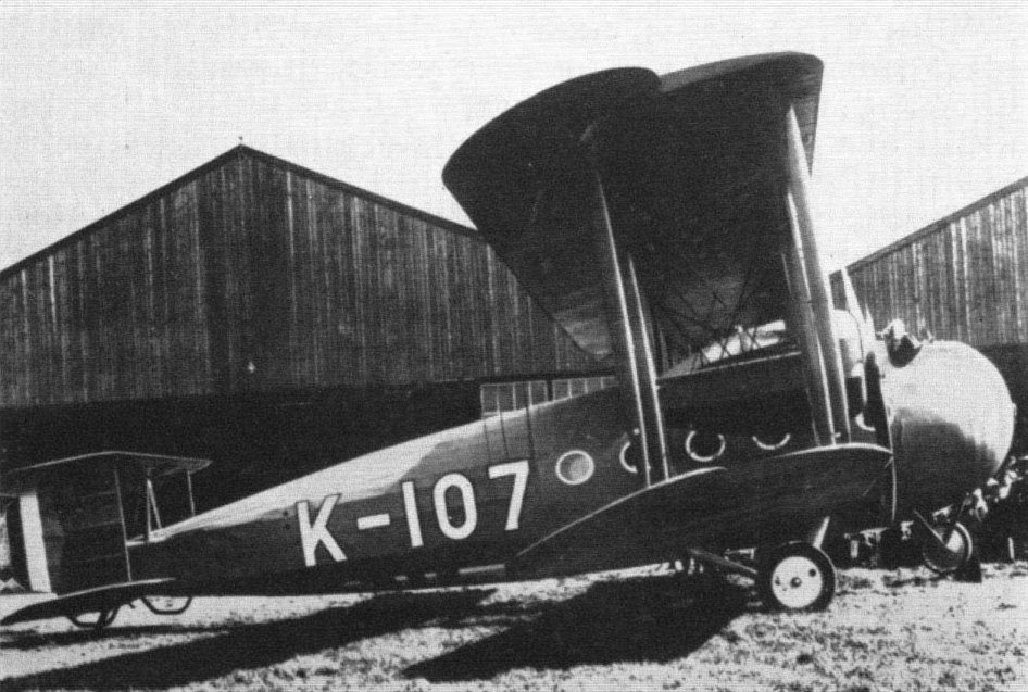
The prototype Vimy Commercial being prepared for its first flight at Joyce Green in February 1919.
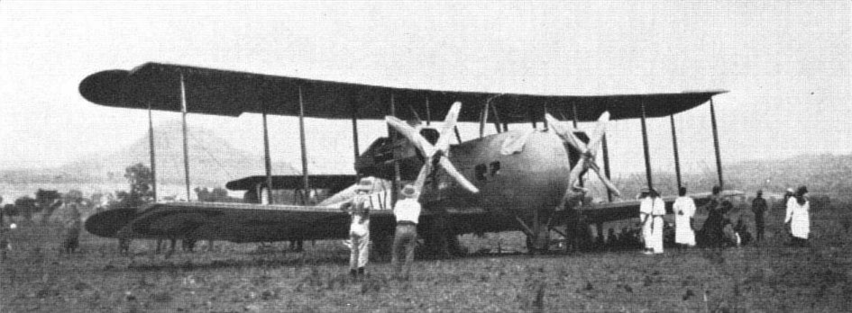
G-EAAV on a landing ground in the Sudan during the attempt by Vickers pilots Cockerell and Broome to fly to Cape Town, 1920.
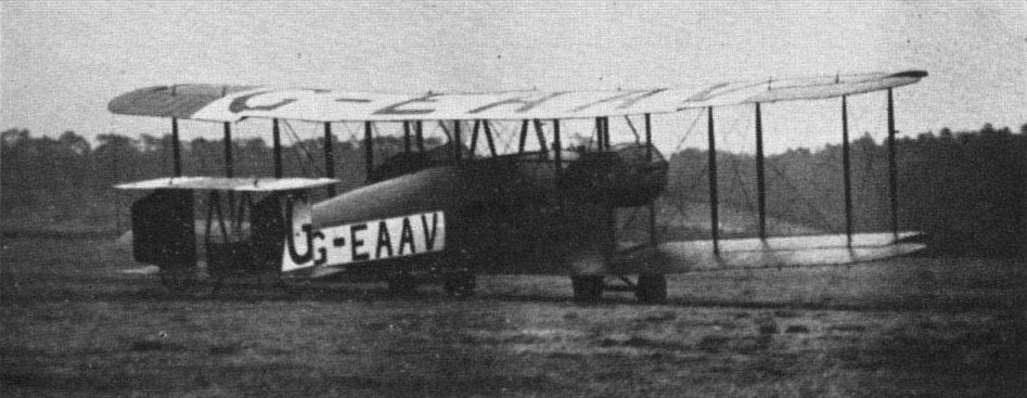
G-EAAV Vimy Commercial (originally K-107 prototype) taking off from Brooklands on 24 January, 1920, for an attempt on the Cape flight.

The Vimy Commercial of Grands Express Aeriens at the 1921 Paris Salon.
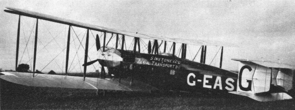
G-EASI Vimy Commercial in its first livery of S. Instone and Co; later it wore that of Imperial Airways.
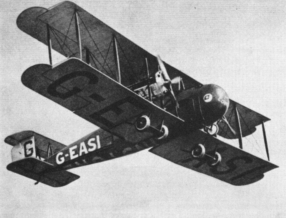
G-EASI taking off at Croydon for Paris in the very early days of civil air transport.

This Russian photograph of the so-called Vimy Commercial supplied to the USSR in 1922 reveals its true identity as a hybrid Vernon with Lion engines.

Vimy Ambulance J6855 in original paint scheme.

Vimy Ambulance J7143 in Iraq in 1924.

Interior of Vimy Ambulance showing unobstructed cabin typical of the Commercial series and continued in the Vernon and Victoria.
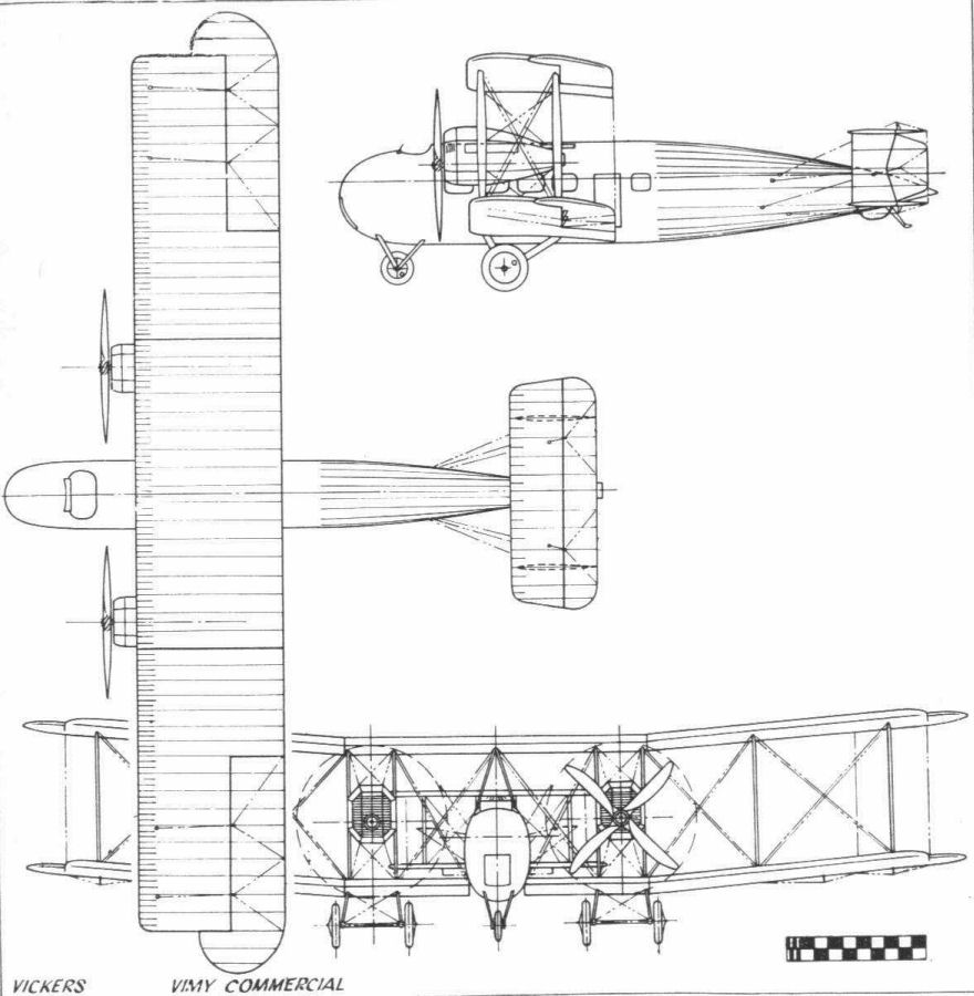
Vickers Vimy Commercial