Книги
WWW
Сайт
Pilots-and-planes
1361
Сайт - Pilots-and-planes /WWW/
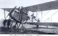
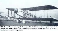
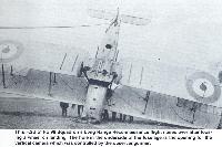
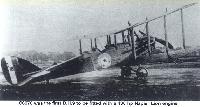
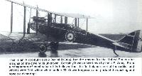
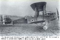
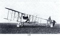
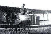
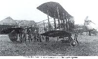
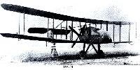
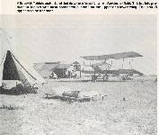
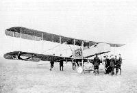
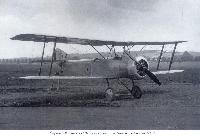
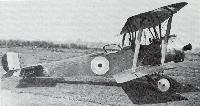
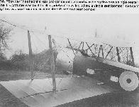
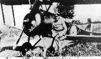
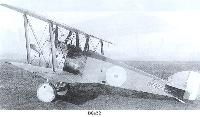
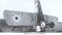
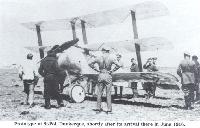
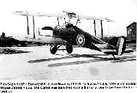
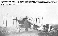
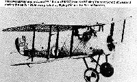
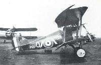
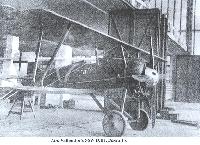
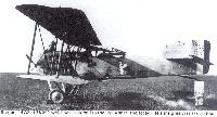
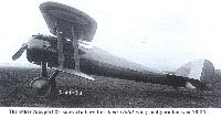
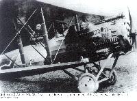
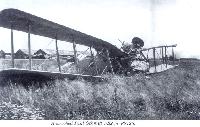
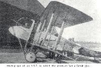
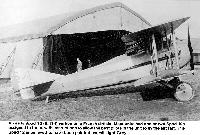
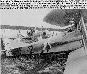
The prototype Bristol F.2A Fighter (A3303) on the landing ground at the Central Flying School at Upavon during September of 1916
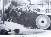
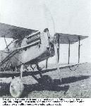
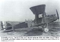
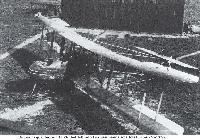
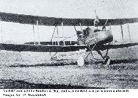
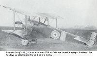
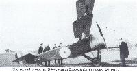
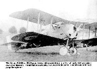
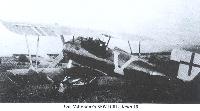
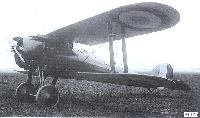
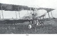
A3303 on the grass at Upavon after it was modified with the round radiator and deeper cowling. At this time the aircraft had no gun mounting in the observer's cockpit
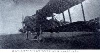
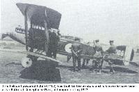
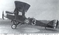
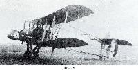
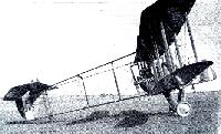
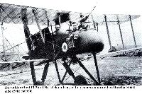
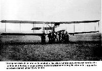
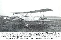
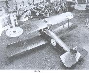
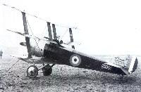
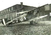
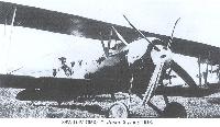
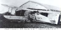
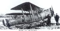
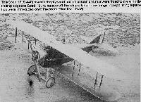
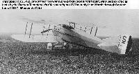
This F.2B (A7106) was powered by a 190 hp Rolls Roys Falcon I engine and was part of the first production batch
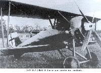
This Falcon I powered F.2B (A7106) was built by the Bristols and is known to have been at No 8 Aircraft Acceptance Park, at Lympne during 1917
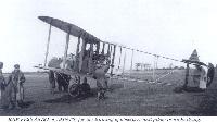
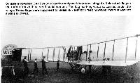
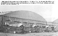
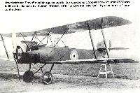
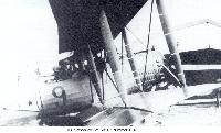
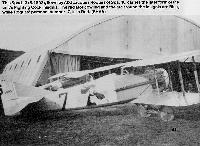
At one time this F.2B (A-7107) served with No 48 Squadron in France. It later flew with the Wireless Training School at Biggin Hill, doing pioneer experimental radio work
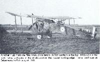
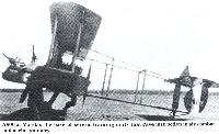
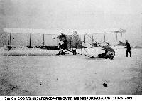
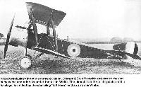
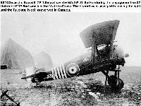
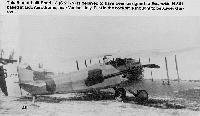
Another F.2B from the first production batch, A7183 carried navigation lights above the lower wing outboard of the struts and on the rudder trailing edge. The aircraft was at Orfordness in February of 1918
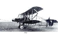
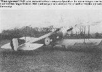
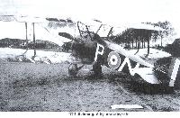
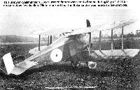
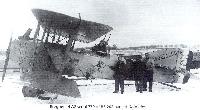
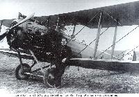
This early production F.2A on the landing ground at Ayr, Scotland during April of 1917 was from the first production batch. It was powered by a 190 hp Falcon I engine.
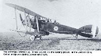
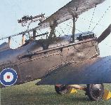
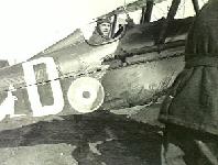
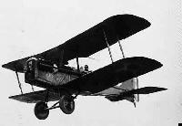
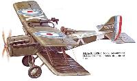
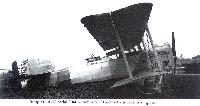
The Bristol F.2B, powered by the 275 hp Rolls-Royce Falcon V12, was the best two-seat fighter. Its powerful engine gave it a speed of 125 mph, faster than its contemporaries, and it had good flying qualities and typical armament.
The Bristol F.2B, powered by the 275 hp Rolls-Royce Falcon V12, was the best two-seat fighter. Its powerful engine gave it a speed of 125 mph, faster than its contemporaries, and it had good flying qualities and typical armament.
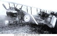
This F.2B (A7238) carries the name TIGER on the fuselage in White. The aircraft has no wheel cover over the starboard wheel. It served at Rendcombe during July of 1918 and was later transferred to No 44 Training Squadron of that same year
F.2B B1134 was assigned to No 35 Squadron after having served with No 48 Squadron which had received the type in March of 1917
To solve the engine shortage problem, an number of F.2Bs were tested during the war with different engines. This F.2B (B1200) at the experimental establishment at Marlesham Beath in September of 1918 was powered by a 200 hp Wolsey Viper liquid cooled engine
The shape of the cowling on this F.2B (B1206) indicates that it was powered by the 230 hp Siddeley Puma liquid cooled engine
It is uncertain whether the White marking just forward of the fuselage roundel on this F.2B (B1208) is the recognition marking of No 20 Squadron or the aircraft's side number (1)
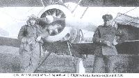
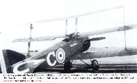
In January 1918 Captain Alan P.Maclean and Lieutenant Frederick H. Cantlon, MC, on No.11 Squadron, RFC, posed in Bristol F.2B C.4844, which they had named 'Rickadamdoo'. They were flying this aircraft when they shot down by Jagdgeschwader I aircraft on 18 March 1918
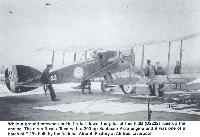
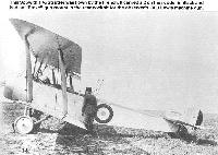
While a ground crewmen holds its tail down, the pilot of this F.2B (D2222) runs up the engine. The aircraft was fitted with a 200 hp Sunbeam Arab engine and it was one of a batch of F.2Bs built by the National Aircraft Factory at Alntree, Liverpool
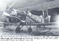
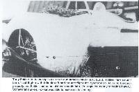
The small hole in the top of the radiator is the gun port for the pilot's .303 Vickers machine gun. The White stripes around the rear fuselage were recognition markings used by No 139 Squadron in Italy during late 1918
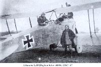
This F.2B (D7966) was issued to No 139 Squadron, Royal Flying Corps on 16 August 1918. The aircraft was lost in combat with Austrian forces some seven days later and the crew, Lts C.E.G.Gill and T.Newey were taken prisoners of war
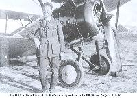
Major B.E.Baker, DSO, MC, AFC, a very successful Bristol Fighter pilot who served with 48 Squadron in 1917. He is seen here the following year in England whilst serving with 141 (Home Defence) Squadron. He later became Air Marshal Sir Brian Baker
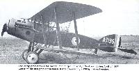
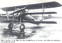
This Bristol F.2B (F4844) is a factory-fresh machine from a production batch of seven hundred produced by Bristol
This F.2B (H6058) was fitted with a 240 hp Siddeley Puma engine and was, along with F.2B (H6055) were the only F.2Bs known to have been built by the Austin Motor Company, although a batch of six hundred were ordered on 25 September 1918
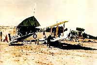
This F.2B of No 111 Squadron had the fabric on the rear fuselage pulled lose. The squadron operated a detachment of Bristol F.2Bs from Sarona, Palestine during late 1917
This Bristol Fighter was reportedly assigned to No 141 (Home Defence) Squadron. It is unclear why the aircraft had the fuselage and fin covered in what appears to be German printed Lozenge camouflage fabric
This F.2b was on the landing ground at Malincourt on the day that the First World War ended, 11 November 1918. The aircraft was powered by a Sunbeam Arab liquid cooled engine and was assigned to "B" Flight on No 8 Squadron
The 230 hp Sunbeam Arab engine differed from the Falcon in a number of ways including the use of front side mounted radiator shutters and a revised exhaust system with a long down sloping exhaust stack
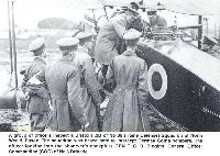
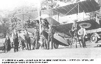
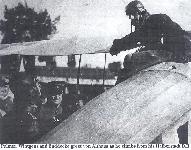
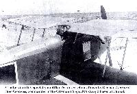
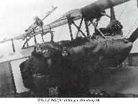
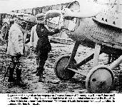
A group of officers inspect a Bristol F.2B of No 39 (Home Defence) Squadron at North Weald, Essex. The squadron was based here to intercept German Gotha bombers. The officer looking into the observer's cockpit is GEN T.C.R.Biggins, General Officer Commanding (GOC) of No 6 Brigade
This F.2B has twin .303 inch Lewis machine guns mounted above the upper wing center section and a twin Lewis mount in the observer's cockpit. It is believed that this F.2B was a night fighter assigned to No 39 (Home Defence) Squadron
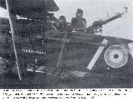
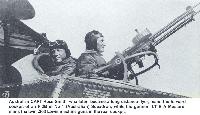
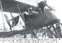
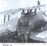
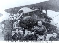
Australian CAPT Ross Smith, who later became a long distance flyer, mans the forward cockpit of an F.2B of No 1 (Australian) Squadron, while his gunner LT E A Mustard, mans the twin .303 Lewis machine gins in the rear cockpit
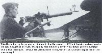
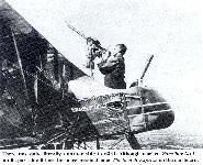
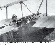
This Royal Flying Corps gunner demonstrates the use of a .303 inch Lewis machine gun in the rear cockpit of an F.2B. The gun is mounted on a Scraff ring mount and is equipped with a Norman sight. The gunner carried seven ninty-seven round drum magazines in the rear cockpit
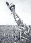
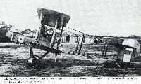
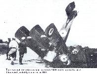
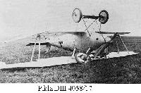
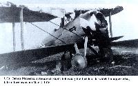
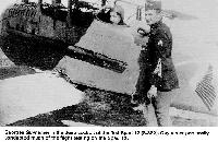
This F.2B of No 98 Squadron's Long Range Reconnaissance flight nosed over after loosing a wheel on landing. The hole in the underside is the opening for the vertical camera which was controlled by the observer/gunner
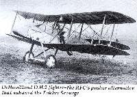
DH2 5925 enjoyed a comparatively long service career: it joined No.24 Squadron in France in February 1916 and was flown back to the UK on 22 May the following year
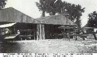
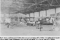
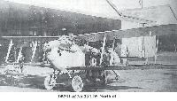
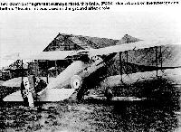
Wooden hangars, with curtain fronts, a DH2 on push-back and two others waiting action - a scene that would be typical of 1915-16 when the pusher fighter was a fortunate answer to the Fokker menace
The D.H. 2. - A small single-seater pusher scout, with 100 h.p. Gnome monosoupape engine. This machine has a strong family resemblance to the D.H. 1.
DE HAVILLAND D.H.2 (No.6011) of No.24 Squadron. Brought down and captured slightly damaged in July 1916. Piloted by Lt. R.H.B.Ker
This D.H.9 served with No 221 Squadron, RAF in Russia during late 1918. Later served with the White Russian Forces in August of 1919
Built by the Vilcan Motor & Engineering Company, and carryinhg the company logo on the interplane struts, B9395 of No 49 Squadron RAF was "The Mackenzie Toolocmbah, Presented"
This aircraft, serial C2161, was one of eighty D.H.9s built by the sub-contractor Berwick & Company of Park Royal, North West London. The aircraft was used at a gunnery school, possibly at Marske
C6109 was among the first production D.H.9s to go to France. It was one of the five sent abroad in late February of 1918. It was operated by No 27 Squadron RAF at Ruisseaville during 1918. On 16 June it was lost in action, with its crew, 2nd Lieutenant H.Wild and Sergeant E.Scott being killed
A standard production D.H. 9, C6277, powered by a Siddeley Puma engine with exhaust pipe extending upwards to discharge over the top wing; this aircraft, possibly of No 99 Squadron, shows the radiator extended beneath the nose.
C6277 is believed to have served at one time at the Biggin Hill Wireless Experimental Establishment as a flying test bed
C6277 is believed to have served at one time at the Biggin Hill Wireless Experimental Establishment as a flying test bed
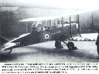
"Britons in Chili No 1" was serialed D1177 and carried the name on the fuselage side in White from 28 December 1918 on. It was assigned to No 120 Squadron RAF after being previously on strength with No 98 Squadron during March of 1918. The D.H.9 was used as a mail-carrier and survived at least until 18 January 1919
Although claimed by some sources to show Lieutenants Gregson and Gaylord with D2803, this is unconfirmed
This is Airco-built D.H.9 (serial D2904), but the reason for the United States star insignia on the cowling is unknown. Certainly it was never flown by the U.S.Army. From a comparision of tonal values it is believed that the fin, balance area of the rudder and wheels were Red, with a White outline. The lower longerons and parts of the decking and nose are clear dope
Subscribed for as "Rigger Parish No 4" according to the nose inscription, D3259 was an Airco-built D.H.9 from a batch which included a number of aircraft that were delivered to overseas air forces
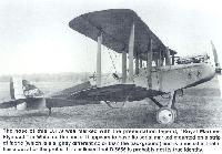
The nose of this D.H.9 was marked with the presentation legend, "Royal Marines Plymouth" in White on the nose. It appears to have its serial marked mounted on a strip of fabric (which is a slightly different color than the background) and is unusual in that it has a dot after the prefix. It is believed that D.5656 is probably not its true identity
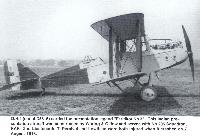
D.H.9 (serial D5816) carried the presentation legend "Faridkot No 3". This Indian presentation aircraft was constructed by Waring & Gillow and served with No 206 Squadron, RAF. 2nd Lieutenants T.Percival and Lowthian were both injured when it crashed on 7 August 1918
"The Scarborough Volunteer" was marked with the fake serial F1203. The aircraft is believed to actually be a Waring & Gillow built D.H.9 (serial D5838)
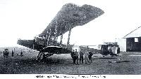
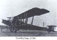
Handley Page 0/400 of 214 Squadron, RAF, at Dunkirk airfield, after a night sortie in which it suffered flack damage
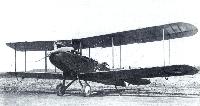
5203 was the third production FE2b built by Boulton & Paul, Ltd., and was a typical early FE2b with the 120-hp Beardmore
No.6338 was a presentation aircraft, but bore its inscription - Ceylon No.3, A Nightjar from Ceylon - only on the port side of nacelle. On February 29 1916, while being flown by 2/Lts. L A Newbold and Chapman it was shot down by Wass of Feld-Flieger Abteilung 3, and is here seen shortly after capture
There was, quite literally, another side to 6341. Although marked Zanzibar No.1 on its port side it bore the more personal name The Scotch Express on the starboard
No.6937 was built by Boulton & Paul, and was marked as a presentation aircraft, Punjab No.29, Rawalpindi
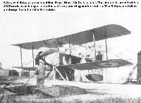
A800 at Marske, the base of several training units that gave instruction in air combar and aerial gunnery
A "presentation" aircraft from the Gold Coast, this F.E.2b served with No 25 Sqn, RFC.
Meanwhile, the FE2b soldiered on although with the increasing numbers of better aircraft available from early 1917 it was soon 'relegated' to the night bomber role - as here with A5478 of 100 Squadron, this unit having formed in February 1917 for this specific role with the FE2b. This picture shows the vulnerable position of the observer in combat.
Meanwhile, the FE2b soldiered on although with the increasing numbers of better aircraft available from early 1917 it was soon 'relegated' to the night bomber role - as here with A5478 of 100 Squadron, this unit having formed in February 1917 for this specific role with the FE2b. This picture shows the vulnerable position of the observer in combat.
A single-seat F.E.2b, 9124 (D9134 ???), of 51 Squadron RFC, some time in 1918. The two small circular apertures in the nose are for the muzzles of its two Lewis guns.
Британский флот также применял FE2. На этом F.E.2D, оборудованном специальным шасси со сбрасываемыми колесами и надувными баллонетами, испытывались возможности безопасной посадки сухопутного самолета на воду. (A6536, here seen at Grain on May 30 1918 with its modified under-carriage, wing-tip floats, and stowed air bags)
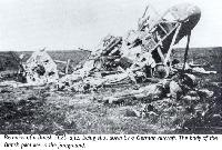
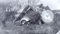
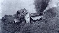
Remains of a British FE2b after being shot down by a German aircraft. The body of the British pilot lies in foreground
S.E.5 (A'4852) of No 56 Squadron at London Colney prior to the aircraft being modified and prior to the unit being transferred to France. This aircraft was flown by Lt W B Melville
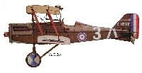
S.E.5 (A'8936) of No 60 Squadron flown by Capt William A Bishop. Such garish markings quickly disappeared since they were officially discouraged
S.E.5a (B595) of No 56 Squadron at Elstree Blanche, France in June of 1917. This aircraft was flown by Lt M E Mealing, MC
S.E.5a (C1904) of No 85 Squadron at St Omer during June of 1918. This aircraft was flown by Billie Bishop
S.E.5a (D3511) of No 40 Squadron was flown by Major Roderic Stanley Dallas, the leading Australian Ace with fifty-one victories
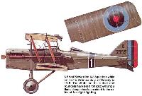
S.E.5a (D5995) of No 143 Squadron while on Home Defense duty at Throwly in 1918. The White on the rudder and roundels have been toned down and a flame damper has been added to the exhaust for night fighting
S.E.5a (F8040) of the 25th Aero Squadron, United States Air Service, Toul, France in November of 1918. Pilot was Lt Raymond C Watts
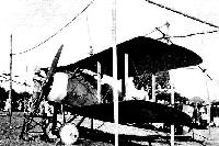
The prototype Sopwith Tabloid was demonstrated in Australia by Harry Hawker during 1914. The aircraft was a side-by-side two-seater with no vertical fin, and skids attached to the undercarriage
Harry Hawker himself demonstrates, on a single-seat Tabloid, how the trailing-edge cut-out could prove serviceable to a photographer as well as to pilot
This Sopwith Tabloid (1205) of No 2 Wing RNAS is armed with a .303 Lewis machine gunmounted above the upper wing center section. Mounting the gun in this manner kept it free of the propeller arc
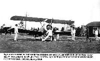
Ground crew hold down Sopwith Tabloid 1205 as it runs up its engine. The aircraft was attached to No 2 Wing of the Royal Naval Air Service and carried early Naval markings which consisted of a Red ring on a White circle carried above the upper wing and below the lower wing
Sopwith Tabloid 1208 was assigned to RNAS Great Yarmouth during 1915. The aircraft had a V-strut undercarriage and ailerons on the upper and lower wings which were connected by light struts
Sopwith workers construct Tabloids in the Sopwith factory at Kingston-on-Thames. The aircraft hull at the right is a Sopwith Bat Boat being built for the Royal Naval Air Service
A Sopwith Tabloid staked and tied down at Royal Naval Air Service air field. This is late production Tabloid with strut connected ailerons on the upper and lower wing. The aircraft appears to be unarmed
The square dark object above the cockpit of Gun Bus number 3833 is the radiator for the liquid-cooled Sunbeam engine. Despite the flag rudder marking, Naval roundels appear to have been carried under the wing tips
Sunbeam-powered Gun Bus 3833 carries early markings consisting of a Union Jack flag on the rudder above the aircraft serial number. The flag marking was also carried under the wings. These flags were supposed to measure 7 feet by 5 feet; however, this rule was not always followed
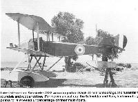
Later in its career, Schneider 3788 was redoped in a Khaki Green camouflage and full British roundels and rudder stripes. For movement ashore, the Schneider and Baby had mounting points for a wheeled undercarriage on their main floats
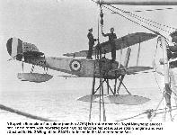
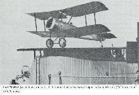
A Sopwith Schneider float plane (number 3788) is hoisted aboard a Royal Navy seaplane carrier. The aircraft was powered by a 100 hp Gnome Monosoupape rotary engine and was attached to No 2 Wing of the RNAS stationed in the Mediterranean Sea
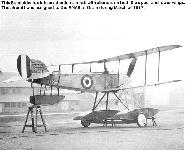
This Schneider is a late production aircraft with ailerons on both upper and lower wings. The aircraft was assigned to the RNAS at Grain during March of 1917
Three Sopwith Schneiders and a Sopwith Baby of the Royal Naval Air Service War Flight are parked in front of their hangars on the Isle of Grain on 13 March 1917. The third Schneider with the dark finish is number 8118
This RNAS Schneider, parked outside the Albany Boat House, Kingston-on-Thames, was experimentally fitted with Hope Linton floats
A Sopwith Baby of an unidentified Royal Naval Air Service unit. The aircraft is armed with a .303 Lewis machine gun mounted on the upper wing center section. The Baby was a follow-on design based on the Schneider
Though bearing no maker's caption, this splendid study of an early 1,5 Strutter, 9382, was nevertheless clearly taken on Sopwith's behalf, and though no guns are mounted (some early 1,5 Strutters were apparently delivered without the Vickers gun, and mountings for the Lewis gun varied) all salient features of the airframe are admirably shown. In the background is an early Martinsyde G.100 - apparently 7263 or 7283 - with its top-wing gun mounting sticking up like the proverbial sore thumb.
Fitted with an "Eteve" machine gun mount in the rear cockpit, Sopwith 1,5 Strutter 7777 was built under license by Ruston Proctor. The 1,5 Strutter was built a number of subcontractors
German officers examine a "Strutter" (A993) of No 43 Squadron which was forced down intact on 28 April 1917. It is believed the serial on the fin was Black with a thin White outline
This 1,5 Strutter (A5252) was assigned to "A" Flight of the Wireless School, at Biggin, Kent. The aircraft was built by Wells and has the lower segment of the cowling removed
N5220 was built by the sub-contractor, Mann, Egerton & Co. of Norwich and carried the company name and address under the tail in White. The aircraft has three lift points on the fuselage, identified by the stenciling "Lift here" and an arrow in White
'No fighting aeroplane ever introduced as many novel armament features as this Sopwith two-seater': the 1 1/2 Strutter, showing synchronised Vickers gun with Sopwith padded screen and Scarff No.2 ring-mounting.
Both single and two seat 1,5 Strutter share the hangar of No 5 Wing, Royal Naval Air Service. The aircraft in the foreground (A2) carried the serial 9395 under the tail in White
This Sopwith 1,5 Strutter was flown by the French. It carried a 2 in the rudder in Black and had an "Eteve" gun mount in the rear cockpit for the observer's .303 Lewis machine gun
This single-seat 1,5 Strutter reveals the two transparent panels in the upper wing center section and the single Vickers .303 machine gun mounted on the aircraft centerline ahead of the cockpit
Одноместный бомбардировщик 1В.1 (This "Strutter" has had the rear cockpit faired over and was being flown as a single-seater. The 1,5 Strutter was built to fill a variety of roles including, a single seat bomber, two seat fighter, two seat reconnaissance aircraft and two seater bomber)
A 1,5 Strutter fitted with hydrovanes and air bags (deflated along the fuselage) for experimental ditching trials
Sopwith 2-seater 9723 was crashed on take-off at Thermi on 10 July 1917 by Buckley, with AM O'Brien as observer
This Sopwith Camel once belonged to Hollywood film maker and aerobatic pilot, Frank Tallman. The aircraft carried the serial N6254 and was used in a large number of Hollywood aviation motion pictures including the Warner Brothers film, "Hell Bent for Glory"
This Camel (B3926) of the Royal Naval Air Service was named Happy Hawkins and based at RNAS Sandown on the Isle of Wright during 1918. It was flown by D.M.B.Galbraith (DSC and Bar) an ace with fourteen victories to his credit while attached to No 8 Naval Squadron. He later served with No 204 Training Depot Station at Eastchurch
This Camel Tsing Tau carried an undersize serial number (B5243) on the rear fuselage in White and the Eagle insignia of the Royal Naval Air Service
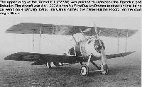
The upper wing of thi Camel F.1 (B7380) was painted to represent the Egyptian god Behudet. The aircraft was the 1,000th aircraft off the Ruston Proctor production line, being delivered on 4 January 1918. The Camel carried the name Ruston Proctor on the cowl
E9968 was a dual-control two-seater of the South Eastern Area Flying Instructors' School at Shoreham
Major H V Champion de Crespigny, MC, DFC, with Lt. A G Jones-Williams, MC and Camel F3991, aircraft 'V' of No.65 Squadron, RAF
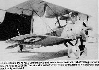
This F.1 Camel (F6302) survived the war and was entered on the British Civil Register on 9 August 1922 as G-EBER. The aircraft crashed some three month later on 4 November and was totally destroyed
Of such clarity is this study of a Sopwith-built Pup that the gunfiring level (which, as Oliver Stewart recalled, 'projected back from under the rear part of the gun') is clearly seen. This might not have been so were the Sopwith padded screen installed, though fittings for this are present on the gun (a Vickers)
Remarkable though the fact may seem, this head-on aspect (with the camera serving as an aiming-point for the Vickers gun, or vice versa) shows practically every basic feature of the Pup. The Sopwith caption reads: 'S.80 - Sopwith "Pup". 80 hp Le Rhone - 1916'
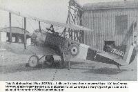
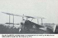
Pup A674 is seen here with 66 Squadron, this unit having re-equipped in March 1917 and moved to France as one of the new fighter units.
This Pup (A674) of No 66 Squadron at Filton, Bristol during early March of 1917 was built by the Standard Motor Company. The aircraft carried the company's badge painted on the interplane struts
This Pup (A674) of No 66 Squadron at Filton, Bristol during early March of 1917 was built by the Standard Motor Company. The aircraft carried the company's badge painted on the interplane struts
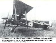
This Pup (A6228) was assigned to No 40 Training Squadron at Waddon (Croydon), Surrey during mid-1917. After they were withdrawn from the Western Front, large numbers of Pups were used by training units
This Pup has the modified cowling indicating it is powered by a 100 hp Monosoupape engine. This aircraft was based at London Colney Airfield during 1917. The aircraft in the background is another Pup (A6235) which carries a White fuselage band
Modifications to Service (as distinct from experimental) Pups were relatively few, one of the best-known being the increase in tailplane incidence from 1 1/2 to 2 1/2 degrees when the Gnome Monosoupape engine was fitted; but the tail surfaces of the one in distress here - and not, apparently, by reason of the sad event depicted, involving the inexpertly numbered 7313 (presumably the Standard-built A7313) - were non-standard
With the 100 hp Gnome Monosoupape engine, the Pup had a distinctive cowling, open-bottomed (or 'horseshoe') and with four auxillary 'lips' round the upper-starboard segment of the nose-ring, as shown
The overall clear doped Linen Whitehead-built Pup is believed to have been assigned to a training unit. The aircraft is unarmed and the vertical fin is in White
This Whitehead-built Pup (B7525) is believed to have been powered by a 100 hp Gnome Monosoupape rotary engine and it appears to be carrying an early type of gun camera in place of the standard Vickers machine gun
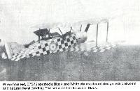
Sopwith Pup (B7575) in the first stages of being repainted with a new high visibility checker board scheme at Edzell near Montrose during 1918
When finished, B7575 sported a Black and White checkerboard design with a Blue fin and natural metal cowling. The serial on the fin was in Black
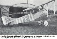
Pup (C215) was painted Blue with White stripes and carried a small Kiwi marking under the cockpit in White. The serial was Black with a White outline
C215 also carried Black and White striped undersurfaces. The aircraft was assigned to the training role at Gosport during 1918
Sopwith Pup (D4031) served with No 3 TDS at Gullance, near Edinburg, Scotland. The fuselage band is believed to be Blue and White
Maurice Buckley flying escort to a Sopwith 2-seater in Pup N6433. He was attached to D Sqn, 2 Wing RNAS at Stavros, on the Balkan Front
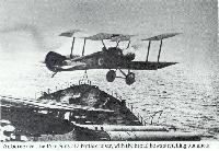
Pup N6453 (which was also tested aboard HMS Furious) departs from the aft ('Y') turret of HMS Repulse - a battle cruiser having two such twin-gun turrets forward and one aft. Note that the departure in this instance is made over the rear of the turret, and not over the guns.
Airborne over the 15 in guns of a battle cruiser, with the broad bows stretching out ahead, the Pup was given a different nautical scale (sailor-caps give further scale and atmosphere at lower port). The flying-off platform seen here was an experimental downward-sloping one, mounted on 'B" turret of HMS Repulse; the pilot Sqn Cdr Rutland; the date 7 October, 1917.
The historic 'Dunning/Pup/Furious', or 'crabbing and grabbing', pictures have received different ascriptions from various authorities, though it showing no Lewis gun on the tripod mounting seemingly records the true 'first', on 2 August, 1917.
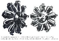
As remarked in the text, there was wide agreement among pilots that the '80 Le Rhone' was the perfect partner for the Pup, and aspects of this delightful French rotary are here presented: left, 3/4 front; right, 3/4 rear.
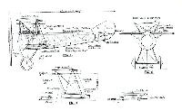
One of the finest sets of official drawings ever prepared, showing not only salient features of the Pup, but details of armament (even the winding-off drum for the ammunition belt) - not to mention the buttons on the seat-cushion!
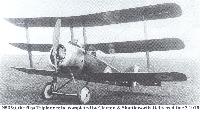
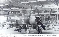
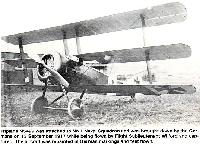
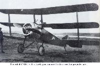
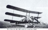
By July 24 1916 the Triplane prototype had been painted overall with PC10 (or PC12), a finish that evidently inspired the name Brown Bread seen in this photograph. Its serial number N500 was applied discreetly in hollow characters
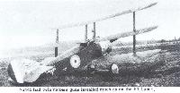
This was not the only occasion on which N500 ended up on it nose. This event probably occured in 1916
Collishaw's second Black Maria was N533, one of the six twin-gun Triplanes built by Clayton & Shuttleworth. He flew it on seven patrols between July 23 and 27 1917; on the latter date he destroyed one Albatros D.V and sent another down out of control
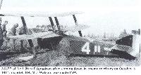
N5377 of No.1 (Naval) Squadron after coming down in enemy territory on October 3 1917; its pilot, FSL M J Watson, was made PoW
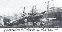
N5386 was one of four RNAS Triplanes that were transferred to the French government, but it was later returned with its original serial number
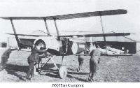
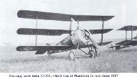
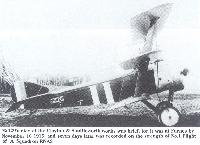
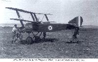
The first Sopwith-built production Triplane, N5420, was sent as a sample to Clayton & Shuttleworth, who were also contractors for the type
N5420's stay at the Clayton & Shuttleworth works was brief, for it was at Furnes by November 16 1916, and seven days later was recorded on the strength of No.1 Flight of 'A' Squadron RNAS
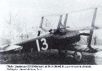
Flight Lieutenant FHM Maynard of No.1 (Naval) in a presentation aircraft, Philippine Island Britons No.1
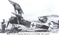
Triplane N5429 was attached to No 1 Naval Squadron and was brought down by the Germans on 13 September 1917 while being flown by Flight Sublieutenan Wilford and captured. The aircraft was repainted in German markings and test flown
Before N5430 suffered its accident on March 12 1918 its serial number had been repainted as A 5430. It is not known why this was done
N5430 was the only Triplane delivered to the Royal Flying Corps. The aircraft was used to intercept raiders while at Orfordness and was modified with an Aldis gun sight mounted above Vickers gun
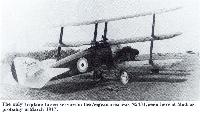
The only Triplane to see service in the Aegean area was N5431, seen here at Mudros, probably in March 1917
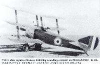
N5431 after repair at Mudros following a landing accident on March 26 1917. Its fin, probably of local manufacture, now has a straight upper/leading edge
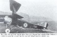
This side view of N5445 cleraly shows how much larger than standard this Triplane's rudder was, and the deeper top decking and cockpit contours can be seen
On the few production Triplanes that were built with twin Vickers gun the armament was installed fully exposed, as seen here
This Sopwith Triplane was one of several aircraft supplied to the French government. The aircraft carries a White 3 on the fuselage side
At least 17, probably 18, Sopwith Triplanes were delivered to the French Aviation maritime and equipped a French naval escadrille at Dunkerque
This aircraft is a flying replica of a Sopwith Triplane based at Old Warden, Bedford. The aircraft carries the full Sopwith company logo on the fin in Black
A group of naval officers watch a Sopwith Triplane on its approach for landing on the grass field at Chingford
This Sopwith Triplane reproduction is displayed by the National Aviation Museum at Rockcliffe Airport, Ontario, Canada
This Sopwith 2F.1 Camel (N6812) was flown by Lt S.D.Culley on 31 July 1918 when he destroyed Zeppelin L53. The Camel was launched from a lighter at sea to perform the interception
A ground crewman pulls though the propeller of this 2F.1 Camel (N7376) of the Royal Canadian Air Force Exhibition Flight. The aircraft was preparing to conduct a demonstration flight at Camp Borden, Toronto, during 1928
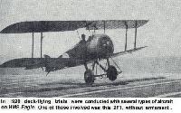
In 1920 deck-flying trials were conducted with several types of aircraft on HMS Eagle. One of those involved was this 2F1, without armament
The unmistakable first form of the Dolphin (with frontal radiator and deep fuselage to match). The original aircraft at Brooklands, May 1917
The first Dolphin prototype as it originally appeared with frontal radiator, unbalanced rudder and fabric-covered rear decking almost up to the cockpit.
The first Dolphin prototype as it originally appeared with frontal radiator, unbalanced rudder and fabric-covered rear decking almost up to the cockpit.
Modified prototype Dolphin with radiators let in to the roots of the upper wings, cut-outs in the bottom wings, and with horn-balanced rudder.
The radiators themselves are barely visible, even in a revised, larger, and more forward form (front view), though the 3/4 rear view shows associated fairings having vents projecting from their peaks.
In the front view (Sopwith No. S.132, captioned '2nd Machine') the rear cut-outs in the bottom wings may be transparent, with the horizontal tail surfaces showing dimly through them. Nevertheless, they mark a definite 'kink' in the trailing edge. (In this view also there are vibration-preventers for the inner main bracing wires).
Though not instantly apparent (perhaps because of the distracting Lewis guns) the fourth form of the Dolphin had a shallower fuselage fore and aft of the cockpit. This form set the pattern for production. B6871
Unidentified Sopwith Dolphin (possibly C3816) at Beaulieu in early 1918. As an operational type the aircraft replaced Spads in a number of fighter Squadrons; some were armed with two Vickers plus two Lewis guns giving them a formidable armament.
A full-standard Sopwith Dolphin night fighter serving with No 1 Training Squadron, armed with twin front Vickers and twin flexible Lewis machine guns.
A full-standard Sopwith Dolphin night fighter serving with No 1 Training Squadron, armed with twin front Vickers and twin flexible Lewis machine guns.
This Dolphin (C3905) was captured and stripped of its wheel covers and tires. The aircraft was formerly assigned to No 23 Squadron. The Squadron marking was a White individual letter on a Black disc
C8043 with No.79 Squadron, RAF, at Bickendorf in 1919
The White square on the fuselage of this Dolphin (C8049) identifies it as being assigned to No 79 Squadron at Bickendorf during March 1918. The aircraft carries the individual identification letter Y in White, which is repeated on the upper fuselage cocking
The White square on the fuselage of this Dolphin (C8049) identifies it as being assigned to No 79 Squadron at Bickendorf during March 1918. The aircraft carries the individual identification letter Y in White, which is repeated on the upper fuselage cocking
Assigned to No 79 Squadron this Dolphin (D3584) was built by Hooper, a builder of customized car bodies. The aircraft was flown by F.W.Gilette
"Дельфин" из 87-го дивизиона RAF, август 1918 г.
The Sopwith Dolphin was designed to give the pilot the best possible field of view - hence the low setting of the upper wing - early trials showed great promise in speed and manoeuvrability (the first Martlesham tests having taken place in mid 1917). It was January 1918 before the first fully equipped unit, 19 Squadron, was operational in France. D3775 is seen here with 73 Squadron.
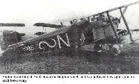
Supine S marking on No.87 Squadron Dolphin which had two outboard Lewis guns, one on each lower wing
The Dolphin's normal armament consisted of twin forward firing Vickers .303 machine guns aimed with the aid of an Aldis gunsight
It is believed that this is either an early production Salamander or one of the prototypes, as indicated by the small fin and rudder fitted to early aircraft. The fin and rudder were enlarged on production aircraft
This Sopwith Salamander (E5429) trench fighter was sent to France during May of 1918 for an operational evaluation. Pilots reported that the Salamander was heavy on the controls
The cowling of the Bentley B.R.2 engine and the unstaggered Vickers guns show well in this close-up of the first Salamander - E5429. Maker's caption: "S.365 - Sopwith Salamander Trench Fighter T.F.2 - May 1/18'.
A production machine before final assembly (Sopwith Salamander E5429 ??). Especially interesting on the production machine, with its staggered guns, is the large case chute, with small link chute above it and the loading handle for the starboard gun peeping up above the cockpit rim just behind. Attachment points for a bomb-carrier are seen under the cockpit.
This Sopwith Salamander carried an experimental camouflage scheme developed specially for the Salamander
This Sopwith Snipe is believed to have been assigned to No 55 Squadrin during the unit's deployment to Iraq
This superb Sopwith study has the maker's caption "S.20 - Sopwith Snipe 200 hp - Type 7.F.1 - 1st. Machine'.
E6531 was a two-seat Snipe used for training during the early 1920s. The aircraft is overall Aluminium dope. The fuselage band is believed to be Red, while the stripe along the fuselage is Black
This overall Aluminium doped 7F.1 Snipe from No 5 Flying Training School at Sealand during the early 1920s was piloted by Flying Officer the Earl of Bandon
E8102 was the Sopwith 7F.1 Snipe flown by MAJ W.G.Barker during the engagement on 27 October 1918 that won him the Victoria Cross. The aircraft was salvaged following the fight and the fuselage is still preserved in Canada
This Snipe (F2336) of 208 Squadron is a late production aircraft which featured horn balanced upper ailerons. The aircraft has a locally produced modification, a small conical shaped propeller spinner
Tied down on the grass at Aulnoy airfield, this Snipe (F2341) has a bomb on the fuselage centerline. The aircraft was used in the ground attack role
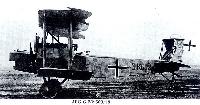
The AEG GIV with the 260hp Mercedes DIVa entered service towards the end ol the year and continued in use until mid 1918. This example is a captured aircraft.
Parachute attached to an AEG G.IV of KG 4. Parachutes were normally issued to German fighters pilots starting in June 1918 so this may have been a test setup.
The business end of an AEG G.IV carrying bombs.
The Mercedes D.IVa was mainly installed in large aircraft like the AEG G.IV.
The Mercedes D.IVa was mainly installed in large aircraft like the AEG G.IV.
The AEG D.1 prototype fighter was unusual in that the airframe was built totally of steel tubing, including the wing spars and ribs. The fact that the wings had a single, steel-tube spar made it possible to reduce the drag-producing interplane bracing to a minimum.
There is little reason to doubt that Leutnant Walter Hohndorf assisted in the design of the AEG D.I. A licensed pilot and engineer, Hohndorf worked as a designer under chief engineer George Konig at the Union Flugzeugwerke, whose aircraft he piloted in several pre-war flying competitions. After volunteering for the air service in August 1914, Hohndorf was assigned to the Siemens-Schuckert Werke as a test pilot and broke a world record with four passengers in a Kondor biplane (September 4, 1915). When he returned to the Front, Hohndorf became a fighter pilot and, as an eight-victory ace, was awarded the coveted Pour le Merite on July 20, 1916. It was not Unusual for Front-line pilots to maintain communication with their former employers or training units. The private pipeline was, in fact, an important Source of up-to-date combat information. That is how Konig, who had become chief designer at AEG, and Hohndorf cooperated on the design of the AEG D.I.
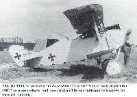
The AEG D.1 prototype, powered by a 160 hp Mercedes D.III engine, made its appearance in May 1917. Flight-testing took place on the AEG airfield in Henningsdorf located on the outskirts of Berlin. Whether Hohndorf participated is not known. During the course of testing at least one of the three prototypes was given a lengthened fuselage (40 cur 15.7 in increase) to improve the longitudinal stability. Ear radiators replaced the nose radiator that blocked forward visibility.
At the end of June 1917, the D.1 was sent to Adlershof for the customary static-load tests, flight evaluation, climb and performance tests and engineering critique, known as the Typen-Prufung (type-test). The static load tests, performed between June 28 and July 3 1917, showed that the wings were sufficiently strong but the fuselage required strengthening. The reinforced fuselage passed the tests on August 1-4 1917. With the load tests successful. Nothing stood in the way of flight investigation by military pilots. On August 21 1917, the 'highly-skilled' Idflieg test pilot, Leutnant Julius Hendrichs, was killed at Adlershof when the AEG D.1 went into an 'ever steeper dive' from 400 meters (1310 ft) and crashed out of control. In spite of Hendrichs' death, the type-test was completed on August 25 1917. The climb figures were to be established at a later date. Surprisingly for a company with such a long record of building military aircraft, the type-test report listed numerous, minor shortcomings, such as missing identification labels, poorly located instruments, rough control actuation, inaccessible engine parts and the like. Idflieg ordered improvements to be made. After which 20 pre-production D.1 fighters would be sent to the Front for combat evaluation. The D.I. had promise, clocking a top speed of 225 km/h (137 mph) and having a climb equal to the Albatros D.V, then a relatively new type in combat.
By this time, one of the three AEG D.1 prototypes had reached Jagdstaffel 14, of which Hohndorf was commander. In the course of flying D.1 4400/17, Hohndorf crashed and was killed on September 5 1917. With two deaths blemishing its record, Idflieg cancelled the AEG D.1 program and the pre-production of 20 aircraft.
Colors and markings
Little information is available regarding the colors of the AEG D.1 fighters but photographs suggest a very pale blue dope was applied overall with white outlines to the national insignia. On photographs of D5002/17, there is evidence of narrow black outlines to the wing leading edges. Serial numbers applied to the fin were also black.
Armament: 2 synchronised 7,92-mm (0-312-in) Spandau machine guns.
Max speed: 137 mph (220 km/h).
Time to 3,280 ft (1 000 m): 2-5 min.
Empty weight: 1,510 lb (685 kg).
Loaded weight: 2,072 lb (940 kg).
Span: 27 ft 10 5/8 in (8,50 m).
Length: 20 ft 0 1/8 in (6,10 m).
AEG D.I 4400/17 prototype at Jagdstaffel 14 in late August - early September 1917. The nose radiator had been replaced by ear radiators to improve the forward visibility.
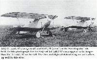
AEG D.I 4401/17 (foreground) and 4402/17 (rear) on the Henningsdorf airfield. In this photograph the fuselage of D.I 4402/17 does appear to be longer than the D.I 4401/17 on the left. The thin and highly-finished wing surfaces show up well in this view.
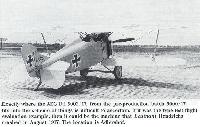
Exactly where the AEG D.I 5002/17, from the pre-production batch 5000/17, fits into the scheme of things is difficult to ascertain. If it was the type-test flight evaluation example, then it could be the machine that Leutnant Hendrichs crashed in August 1917. The location is Adlershof.
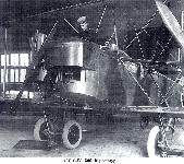
Tightly squeezed into an experimental turret, the gunner demonstrates the operation of a 2 cm Becker cannon mounted in the AEG G.IV 1096/16 bomber. Effective firing trials against ground targets were performed in October-November 1917. The turret was capable of rotation. The curious, heart-shaped machine gun support on the upper turret is likewise an experimental installation.
Albatros C.III powered by a 160 hp Mercedes D.III engine ready to leave the Albatros Werke factory at Johannisthal for flight acceptance.
The control wheel and instrument board of a C III type Albatros, showing radiator in upper plane and compass upside down just below it.
Albatros C.VII(Bay) 7720/16 shows there's no accounting for human error. The serial number on the tail, C.7720/17, has been incorrectly applied!
This aircraft flown by a Fliegertruppe unit stationed at Gross Auz (near Alt Auz, now Vec Auce, Latvia) in the winter of 1916-1917
Hptm. Schlegel finds an interesting place on the exhaust of his C.VII to pose for a photograph; one imagines the engine must not have been run for some time. Below the fuselage is the antenna weight for the wireless, and the ear radiator is partially blocked for cold weather operation. Meanwhile the observer practices with his binoculars.
Экипировка экипажа этого "альбатроса" значительно отличается. Летчик облачен в кожаную куртку и шлем; стрелок одет в мундир, и от ветра его предохраняет шарф и шлем с маской
Ltn. Frankel (left) and Offstv. Gunther seated in an Albatros C.VII of Fl. Abt. A 299 in 1917
Ltn. Frankel (left) and Offstv. Gunther seated in an Albatros C.VII of Fl. Abt. A 299 in 1917
Albatros D.II 491/16. Most historians believe victories 4 - 16 were obtained in this machine.Richthofen was awarded the Pour le Merite, or Blue Max for victory no.16. Victories 1 - 4 were obtained in the similar Alb. D.I.
Прототип истребителя "Альбатрос" D.I
The Albatros DI prototype with vertical exhaust pipe and unbalanced elevator.
The Albatros Dl was introduced to counter the DH2 and early Nieuports that had proven superior to the Fokker Eindeckers. Along with the DII they became standard equipment lor the new fighter units - the Jastas.
The Albatros DI prototype with vertical exhaust pipe and unbalanced elevator.
The Albatros Dl was introduced to counter the DH2 and early Nieuports that had proven superior to the Fokker Eindeckers. Along with the DII they became standard equipment lor the new fighter units - the Jastas.
Захваченный англичанами на месте вынужденной посадки "Альбатрос" D.I лейтенанта Бюттнера из 2-й истребительной эскадрильи германских ВВС / Side view of Albatros destroyer, type D.I, 1916-17.
The Jastas were highly successful in regaining air superiority at any point on the front to which they were attached; however, the problem was that there were simply not enough of them to cover all areas. This Albatros Dl belonged to Karl Buttner of Jasta 2 in late 1916.
The Jastas were highly successful in regaining air superiority at any point on the front to which they were attached; however, the problem was that there were simply not enough of them to cover all areas. This Albatros Dl belonged to Karl Buttner of Jasta 2 in late 1916.
Karl Schafer in his Albatros D.II (1724/16) of Kampfstaffel 11. Marking is a white circle, edged black, on fuselage and both elevators; note rearview mirror.
This head-on view of an Albatros D.II shows off the fine lines of the aircraft, which are marred somewhat by the Windhoff radiators mounted on each side of the fuselage.
That the heavy Becker cannon was installed and tested on the Albatros D.II fighter defies belief. According to Idflieg records firing trials with this fighter were performed in November 1916. This combination may have appeared briefly at the Front for evaluation.
Albatros D.III Jasta 5. Green & Mauve/Light Blue horizontal surfaces. Black and White fuselage, Green tail unit & Red spinner, wheel cover and tail trim.
Albatros D.III 789/17. Richthofen flew three all red D.IIIs and obtained victories 37 - 53 in them/ Machine 789/17 displayed an Albatros logo on its rudder.
Albatros D.III Jasta 11, Douai, Spring 1917. Green & Brown/Light Blue horizontal surfaces. Red, White & Clear-doped fuselage and rudder.
Udet stands in front of his Albatros D.III D.1941/16 on a freezing January morning in 1917.The mechanics are warming the engine with pre-warmed oil and hot water. Even so, the coolant could quickly freeze in such cold temperatures. Ironically, the Militaar Nummer, 1941/16, reflects the year Udet would later die.
Albatros D.III D.2125/16 of Jasta 1 marked in black with the initial of its usual pilot, Leutnant Freiherr von Stenglin.
Albatros D.III(OAW) of Jasta 57 in flight in the spring of 1918. This aircraft is possibly Paul Strahle's machine D.2385/17.
Leutnant Max Romer's Albatros had a wash applied over the national markings. It was most probably yellow, the Jasta 10 color. The lightning bolt was Romer's individual insignia. Previously a pilot with Flieger-Abteilung (A) 208, Romer had been with JG I just four weeks when he was killed on 2 October 1917.
Albatros D.III of Jasta 19 in the spring of 1917; the pilot is Lt.d.R. Franz Dotzel. Jasta 19 used personal insignias based on the pilot's last name with the letters in black and white.
Albatros D.III(OAW) flown by Gunther Dobberke in Jasta 45 (or perhaps Jasta 60) in the spring of 1918.
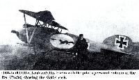
OAW-built D.III of Leutnant Otto Fuchs with the pilot's personal emblem of the fox (Fuchs) chasing the Gallic cock.
Jasta 27 lineup; a single Roland D.II is at left in a lineup consisting mostly of Albatros D.III and D.V fighters.
Пулеметы "Шпандау" являлись германской копией американского "Максима". Водяное охлаждение ствола было заменено на воздушное
Albatros D.V 1033/17 & Albatros D.V 4693/17. Both machines were finished in this scheme. Victories 58 and 59 were obtained in 4693/17, and on July 6, 1917, Richthofen was shot down and seriously wounded in 1033/17.
Albatros D.V D.2030/17, Jasta 22, Lt. Alfred Lenz, Vivaise, August 1917. Green & Mauve/Light Blue horizontal surfaces. Overall Green fuselage.
Albatros D.Va, Bogohl 6, Staffel 19, Lt. Brauer. Green & Mauve/Light Blue horizontal surfaces. Overall Clear-doped fuselage with Yellow nose & tail
Albatros D.Va, Jasta 84, Lt. Weber. 5-Color Lozenge horizontal surfaces. Clear-doped fuselage. Black & White tail.
Albatros D.Va, Jasta 62, Lt. Max Nather, Balatre. April-May 1918. Green & Mauve/Light Blue horizontal surfaces. Overall Black fuselage with Red spinner.
Hans Waldhausen and groundcrew stand in front of his Albatros D.V D.2284/17. This was the machine in which he was captured on 27 September 1917
This Albatros D.Va was flown by Walter Boning during his time with Jasta 76b. The machine was photographed whilst up on a trestle having its guns fired into the distant butts
Hasso von Wedel's Albatros D.Va in 1918 with his 'Richtrag' marking on the fuselage, repeated on the top of the fuselage
Jasta 27 lineup; a single Roland D.II is at left in a lineup consisting mostly of Albatros D.III and D.V fighters.
Albatros D.Va, D.2343/17, Jasta 61, Vzfw. Jautsch. Green & Mauve.Light Blue horizontal surfaces. Overall Clear-doped fuselage with Green nose & White rudder
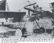
E.I/15 was the first Fokker Eindecker to enter combat. It was flown by both Oswald Boelcke and Max Immelmann.
Fokker E.III (Serial No. Unknown) Due to engine failure, Richthofen crashed and totally destroyed his first E.III at Mont-Murville, late spring 1916.
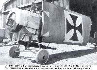
This Austro-Hungarian E.III, 03.43 was armed with a Schwarzlose M 7/12 machine gun during 1916. It was flown by both Flik 8 and 19.
Fokker E.IIIs were also flown by naval units. This aircraft was assigned to the Austro-Hungarian Navy during 1917.
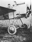
This Fokker M.5/MG (E.I) was assigned to a front line unit. The gun button and magneto cut-out spade are visible on the control stick. The weapon was a 7.92mm 08/14 Parabellum machine gun.
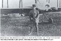
Oberleutnant Max Immelmann poses in front of his Fokker E.I. The wartime censors have retouched the original photo, removing the details of the engine and gun.
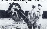
The Bavarian Kronprinz discusses the merits of a Fokker E.III with Tony Fokker. This aircraft has an oil sump under the lower cowling.
Corporal Boehme in the cockpit of a Fokker M.14 (E.II) serial 43/15 (33/15 ???). The wooden propeller has a German cross in the blade.
A Fokker M.14 (E.II) at the factory, ready for rail shipment to the front. The sign states that reassembly instructions are on the seat and that they are to be followed precisely.
Lieutenant Von Zastrow's Fokker M.14V (E.III), 401/15 at a German Army field near the front. The cowling has been removed, indicating that the crew had probably just completed some sort of maintenance on the engine.
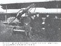
The pilot and ground crew of a Fokker M.14V (E.III) 401/15 pose with their aircraft on a German Army front line base. The aircraft was assigned to Lieutenant Von Zastrow.
The air park at the Fokker factory in Schwerin. A number of Fokker M.14Vs (E.IIIs) are parked just inside the fence and the aircraft on the grass include an E.III (left) covered in a clear cover intended to make the aircraft less visible. This technique was tested, but found to be of little value and was abandoned.
A Fokker E.III (345/15) flown by Lieutenant Buddecke on the Turkish Front. The square later became the official insignia of the Turkish Air Force, first in Black and White, then later in Red and White.
This Fokker M.15 (E.IV) was set up at the factory to shoot a number of documentation photos of the three machine gun installation. Although Boelcke tested such a gun installation, he reportedly disliked it.
This three-gun Fokker M.15 (E.IV) is unusual in that it does not have the cooling intakes around the front of the engine cowling.
Tony Fokker in the cockpit of a three gun armed Fokker M.15 (E.IV). Fokker flew a number of test flights with this aircraft and on one flight the synchronizer failed to function properly and Fokker put some sixteen rounds into his propeller, nearly shooting it away. Somewhat shaken, Fokker was able to make a safe landing.
This is the gun installation on E.IV 122/15. Only the first three M.15 airframes had the structure to mount three LMG08s and only 122/15 had the fuel gauge set between the starboard and center guns. A compressed air tank replaced the port gun and may have been an experimental apparatus to pressurize the aft auxiliary fuel tank. With the exception of the previous photo, 122/15 was usually seen without the wind-driven generator seen on other E.IVs for this purpose. (Colin A Owers)
A group of German pilots pose with one of their unit’s Fokker M.15s (E.IVs) on a frontline airfield. The Eindecker was a strong aircraft easily able to support the weight of the two men setting on the wing tips.
Fokker M.15s (E.IVs) under construction in the Fokker factory at Schwerin. There are at least fifteen aircraft in various stages of assembly.
Fokker M16E of 1915. To be historically accurate it is the Fokker M16 Karausche. The E (= Einsteilig) is a spurious designation added after WW1. You know it, there was also a two-bay Fokker M16, which got the spurious designation M16Z.
Прототипом D I был опытный самолет М18. Его конструктивной "изюминкой" было установленное на фюзеляже верхнее крыло. На фотографии - Э. Фоккер, обычно выполнявший первый полет при испытаниях нового самолета.
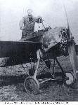
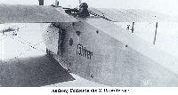
Anthony Fokker in the M 18 prototype.
Anthony Fokker in the M 18 prototype.
Three-quarter rearview of D.I 141/16, the sole known aileron-controlled Fokker D.I. The aileron-controlled wings required a new wing design, and this was not completed before production of the Fokker D.I was terminated.
Fokker D.I 159/16 is a rare example of a D.I carrying a personal marking. A large stylized letter "A" has been marked on the fuselage side, carefully applied in order to leave the "F" of the military number intact. The shadow of the photographer and his camera can be seen in the left bottom of the picture.
Fokker D.I fuselage showing how the 120-hp Mercedes D.II engine, the exhaust pipe and the water header were mounted.
An under-construction view of the forward fuselage illustrates the box-like structure of the upper wing center-section strut arrangement, complete with bracing wires and turnbuckles.
Опытный экземпляр "Фоккера" с уменьшенным размахом крыльев и одностоечной бипланной коробкой.
The only single-bay Fokker D.II (M 17) to see service in Germany was operated by the German navy under the designation LF238, with a seven-cylinder 80-hp Oberursel.
The only single-bay Fokker D.II (M 17) to see service in Germany was operated by the German navy under the designation LF238, with a seven-cylinder 80-hp Oberursel.
Fokker D.II 536/16 flown by Ltn. Otto Dessloch was forced to land in Switzerland on 13 Oct. 1916. Here a member of the Swiss home guard inspects the aircraft. Dessloch had installed a rear-view mirror on the right side of the cockpit. A Morell Phylax tachometer is fitted to the tip of the port lower wing.
Three-quarter rearview of 543/16. The square backgrounds of the upper wing crosses have also received a coat of dark paint, leaving the crosses with a similar rough white border as the one seen on the fuselage cross.
The same aircraft seen in the two previous photos was again photographed soon afterwards, now sporting a freshly-applied two-color camouflage scheme applied to the sides of the fuselage. This picture may have been taken in order to document this new style of camouflage. It already resembles the streaked finish which is so well-known from the Fokker D.Vs and Dr.Is, but the pattern is more opaque than that of most those. The metal nose parts are still left in the turned finish. In numerical sequence, D.II 1505/16 was the 81st D.II manufactured, and it was probably photographed in late October or early November 1916. Note that the fuselage cross has now been applied, and the gaps in the military number on the fuselage sides have been closed.
Серийный "Фоккер" D.II с синхронным пулеметом LMG 08/15.
Fokker D.II 1535/16 armed with a Spandau LMG 08/15 gun.
Fokker D.II 1535/16 armed with a Spandau LMG 08/15 gun.
Fokker D.II with a ‘shark mouth’ painted cowling. The ‘Manx Legs’ on the wheel discs must have looked comical when in motion during take off and landing.
Fokker D.III 351/16, the true production prototype
Here the aircraft is photographed later at an unknown location, complete with armament installed. Note that the fuselage cross is now also in place, and the wheel covers are finished in a light color, possibly white?
Here the aircraft is photographed later at an unknown location, complete with armament installed. Note that the fuselage cross is now also in place, and the wheel covers are finished in a light color, possibly white?
Richthofen’s 152/17 alongside Boelcke's Fokker D III 352/16 on display in the entrance hall of the Zeughaus Museum .
Unarmed but with the propeller in place, Fokker D.III 353/16 is seen here at a collection point. Behind it the comet-marked fuselage of a Gotha bomber can be seen. This picture may have been taken after the early Fokker-fighters were banned from frontline service in early December 1916.
View of the engine installation on an unarmed D.III minus wings. The aircraft seems to feature camouflaged fabric while the forward metal parts remain in natural finish. Parked next to it is a Fokker D.V fuselage with white cross background while the cross itself remains to be applied.
Dutch air service Fokker D.III 1619/16, the D III in its definitive production form in which ailerons replaced wing warping for lateral control.
Anthony Fokker in the cockpit of the unidentified single-seat fighter prototype developed from the D.II. The upper wing is the major difference; it is swept-back with horn-balanced ailerons. This was probably the first M.22 prototype. (Peter M. Grosz collection/STDB)
Leutnant Hans Elmenhorst died in the crash of Fokker D.V 2687/16 in May 1917 at Bavarian Flieger Schule 1 at Schleissheim.
"Фоккер" D.V 2688/16 без вооружения на немецком полевом аэродроме. Эта машина использовалась в 1917-18 гг. для тренировки летного состава.
D.V 2690/16 Number "6" was an armed Naval defense fighter. In a seemingly staged scene, the pilot is getting some last-minute instructions.
Fokker D.V 2710/16 (M.22 w/n 1068) was photographed at Schwerin in October 1916 before it was sent to Adlershof for a static load test.
Fokker D.V 2786/16, was accepted at Schwerin in March 1917 and served with the Kampf-Einsitzer Schule Warschau (Warszawa). It was marked with an artistically-applied "Billiken" figure, which was a popular talisman figure in the early years of the 20th century. (Peter M. Grosz collection/STDB)
Fokker D.V 655/17 was an early machine from the second batch of 50 aircraft. Very few photos of aircraft from this batch have been found, and none of them show an armed aircraft. On this plane, the wing struts are painted in light green or light blue.
"Фоккер" D.V без вооружения на немецком полевом аэродроме. Эта машина использовалась в 1917-18 гг. для тренировки летного состава.
View of the engine installation on an unarmed D.III minus wings. The aircraft seems to feature camouflaged fabric while the forward metal parts remain in natural finish. Parked next to it is a Fokker D.V fuselage with white cross background while the cross itself remains to be applied.
A Fokker D.VII (1450/18) piloted by Hans Shultz when it was shot down by Lt C.H.R. Lagesse of 29 Sqdn.
A Fokker built D.VII flown by the Polizerflieger (Air Police) Staffeln at Paderhorn during the early 1920s.
353/18, an early standard Fokker D.VII with a 160-hp Mercedes engine in the factory standard vertical Green streaked camouflage on the fuselage and 45 degree streaks on the horizontal top wing and tail surfaces.
A D.VII built by the Albatros company is identified by the all-white fin and rudder as well as the distinctively different (from Fokker) lettering on the fuselage and the louver pattern on the engine cowling.
This early machine built by O.A.W. (2009/18), was the first Fokker D.VII captured intact by the French. The aircraft, repainted with French markings, was photographed in France then sent to England.
This Fokker D.VII of Jasta 65 carrying the personal markings "U.10", was captured by the American 95th Aero Squadron, signified by the kicking mule that has been added to the forward fuselage.
The original crosses had been cut off for souvenirs, the repainted crosses are smaller. This machine was restored to its WW I configuration and is now on display in the Smithsonian.
The small White square on the fuselage of this Fokker built D.VIIF contains rigging instructions. The detail of the MG charging handles (cocking handles) can be seen.
Leutnant Ulrich Neckel flew this black-and-white striped Fokker D.VII during his time as last wartime leader of Jasta 6.
Test pilots at the Albatros Works stand in front of their charge, a brand new D.VII. Tape has been applied to each rib position.
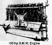
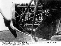
The installation of a 185-hp BMW IIIa engine increased considerably the D.VII’s performance, especially at high altitude.
Final assembly of a D.VII that has not had its temporary wooden wheels replaced by the spoked wheels and wheel covers.
Fokker D.VII (OAW) 4464/18 flown by Ltn Hans Jungwirth of Jasta 78b. Light Blue tape has been applied to each wing rib.
Fokker F.I 102/17. A pre-production machine finished in turquoise with gray/green streaked pigments. Victories 60 and 61 were obtained in this machine.
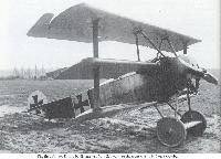
Fokker Dr.I 127/17. Contrary to popular belief. Richthofen's triplanes were delivered to the front in the standard production colors - dark green streaked onto natural doped linen. Later, as time allowed, the red coloring associated with Richthofen was applied. Dr.I 127/17 was finished in this scheme when used to obtain victories 71, 74, and 76, and was painted all red soon afterwards.
Fokker Dr I 152/17. Victories 64, 65, and 66 were obtained in this machine. Although painted all red in March 1918, Richthofen did not score any victories with this machine in that state of decoration.
Fokker Dr I 425/17. This machine was decorated with various national insignia - Iron Cross (refer to style used on 152/17), and Balkenkreuze (shown here). Dr I 425/17 was in this state of decoration when used to obtain victories 79 and 80, and on April 21, 1918, when Richthofen was shot down and killed in this triplane.
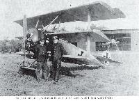
Один из первых экземпляров "Фоккера" Dr.I с заводским номером 115/17, западный фронт, сентябрь 1917 г.
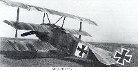
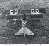
The first Fokker Dr I to be dispatched from Schwerin to the front was 115/17 on 4 October.
The first Fokker Dr I to be dispatched from Schwerin to the front was 115/17 on 4 October.
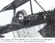
Gontermann, his face smeared with Frostsalbe as a safeguard against frostbite, in 115/17, shortly before his last flight.
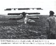
Gontermann in 115/17 about to take off from La Neuville. Annotations indicate that this was the fatal flight on 30 October.
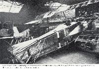
With fabric partly removed, von Stapenhorst’s captured Dr I 144/17 is seen here at the Enemy Aircraft View Rooms in Islington, where it was examined
Rudolf Stark poses with Dr.I 146/17 after his first flight in it 14 May 1918. The airplane was transferred to Jasta 34b from Jasta 11 and still bears the markings of Jasta 11.
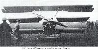
The Fokker Dr1 was, despite its obvious failings, well liked by many of the pilots, a number of whom were reluctant to trade in their mounts even when technically superior fighters became available. It was one of those aircraft that acquired a mystique, a mystique that still survives today!
The Fokker Dr1 was, despite its obvious failings, well liked by many of the pilots, a number of whom were reluctant to trade in their mounts even when technically superior fighters became available. It was one of those aircraft that acquired a mystique, a mystique that still survives today!
Oberleutnant Karl Bodenschatz, Adjutant of JG 1, in front of 150/17 at Avesnes-le-Sec, late December 1917.
Manfred von Richthofen flew several Fokker Dr.Is while commander of Jagdgeschwader 1 and, contrary to popular belief, they were not all overall Red. This Dr. I (152/17), had the forward fuselage and lower two wings in Olive Green.
Richthofen’s 152/17 alongside Boelcke's Fokker D III 352/16 on display in the entrance hall of the Zeughaus Museum .
Another view of Dr.I 157/17 of Jasta B displays the black cowling with white faceplate which also identified triplanes of this unit.
Leaving Boncourt for Masny in preparation for the March Offensive, Leutnant Werner’s 198/17 is taken from the aerodrome to the railway loading point.
The cowling of Goettsch’s 202/17 has been all but torn off by the flailing action of a valve-operating pushrod which worked loose.
Rearview of Paul Baumer's Fokker Dr.I 204/17. The black and white Staffel marking is applied on the horizontal tail surfaces. Note the additional iron crosses on the upper side of the lower wing and the tail. This was done to prevent the aircraft from being wrongly identified as a British Sopwith Triplane. The engine cowling was black, and the prop appears to be a captured example.
Baeumer in front of 204/17 with his mechanics (left to right): Unteroffizier Henke, Baeumer, Gefreiter Meissner and Monteur Stahlmann. The aircraft was probably powered by a Beute (captured) Le Rhone engine.
Oberleutnant Hermann Goering, Staffelfuehrer of Jagdstaffel 27, in his triplane which is almost certainly 206/17
This triplane is believed to be 212/17. It is known to have been flown by Leutnant Karl Gallwitz, seen (second from left) with his mechanics at Bavichove .
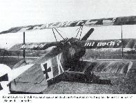
Kempf's 213/17 in full warpaint leaves no doubt as to the identity of the pilot, ‘kennscht mi noch?’ (Remember me still?)
Ltn. Wilhelm Papenmeyer sitting on the fuselage decking of his Fokker Dr.I 214/17. His second mechanic, Monteur Ziegler also poses for the snapshot. The remains of an Iron Cross marking, which had been applied on the forward part of the upper horizontal tail surfaces, can still be made out. By the time the photo was taken, the black and white Staffel marking covered it completely. (G. VanWyngarden)
Leutnant Emil Koch (left), Staffelfuehrer of Jasta 32b, and his OzbV, Leutnant Freiherr von Hunoldstein. pose with two blue-nosed Jasta 36 triplanes on Guesnain aerodrome, March 1918. This machine is 220/17
JG II commander Hptm. Adolf von Tutschek seated in his new Dr.I 404/17, preparing to take off. One mechanic is preparing to swing the propeller while another one is holding down the tail. A newly-arrived, disassembled Dr.I can be seen in the background, as well as some older Albatros D.Va fighters of Jasta 12.
Richthofen's red-painted 425/17 seen in its final state of decoration shortly before he was brought down and killed in this triplane.
The most famous airplane of WWI, Dr.I 425/17 was the all-red Fokker flown by Manfred von Richthofen when he was killed in action on 21 April 1918. Examination of fabric from this aircraft reveals no camouflage, indicating it was painted for the Red Baron at the Fokker factory.
The most famous airplane of WWI, Dr.I 425/17 was the all-red Fokker flown by Manfred von Richthofen when he was killed in action on 21 April 1918. Examination of fabric from this aircraft reveals no camouflage, indicating it was painted for the Red Baron at the Fokker factory.
Vizefeldwebel Otto Esswein of Jasta 26 poses with his new triplane, 426/17 at Erchin in early April.
It is probably 493/17 a machine that Kempf is known to have flown, using it to score his fourth and final victory on 8 May.
This view of Wenzl’s Jasta 11 triplane. 588/17, taken at the same time as the previous photograph, shows the standard JG I thick Balkenkreuze.
Leutnant Gerhard Anders, Staffelfuehrer of Jasta 73, seen flying, apparently in June 1918, from St Remy le Petit aerodrome.
The wreckage of Oberleutnant Kurt Wolff’s 102/17 near the village of Nachtigall, after he had been shot down and killed on 15 September 1917.
On 29 October 1917 Vizefeldwebel Josef Lautenschlager of Jasta 11 was shot down and killed while flying 113/17 by a Vizefeldwebel pilot of another Jagdstaffel in IV Armee.The similar appearance to the Sopwith Triplane, caused confusion between friend and foe alike
The wreckage of Leutnant Guenther Pastor’s triplane, 121/17. There are no details of the nature of any maneuvres undertaken before the aircraft, apparently descending in a normal gliding attitude, suffered structural failure of the top mainplane, which resulted in the fatal crash.
On 13 March 1918 Leutnant Lothar von Richthofen, Staffelfuehrer of Jasta 11, suffered an upper wing leading-edge failure on 454/17 when diving steeply during a fight at 4,000 metres.
The pilot of 475/17 was probably Leutnant Emmerich Honig, Jasta 14 , who was killed when he stalled and crashed on 4 June 1918 on Phalempin aerodrome.
Dr.I 558/17 seen here at Cappy airfield in mid 1918 following a crash landing by Feldwebel Fritz Rumey
"Фоккер" E.V оберлейтенанта Эриха Ловенхардта, август 1918г.
The Fokker V.26, which became the E.V, won the Second Fighter Competition despite using a low-powered 110 hp Oberursel. This spectacular example was flown by Jasta 6 in August 1918 until a series of fatal accidents were attributed to poor assembly and quality control at the factory. The E.V had to be withdrawn for wing replacement. By the time the planes returned in October, Idflieg had decided that all fighters would be in the 'D' category and the E.V became the Fokker D.VIII.
Two single views of the "waveline band''-marked E.V, seen as the third plane in the previous lineup photos. This aircraft may have been E.V 116/18, which was accepted on 16 July, like several other E.Vs delivered to Jasta 6. A very close look shows that this number appears to have been re-marked below the machine gun. The same practice was continued soon afterwards on the O.A.W.-built D.VIIs that Jasta 6 received as replacement for the "Parasol". (Peter M. Grosz Collection/STDB)
Another set of photos of a newly-arrived E.V, this time featuring 143/18 (w/n 2784, accepted 20 July) and Vzflgmstr. Carl Kuring from MFJ II. This fighter was delivered to the unit on 11 August, and the photos were likely taken on that day. Kuring had joined the Staffel on 6 November 1917. Thus he was one of the most experienced members of the unit, and was an obvious choice as a pilot for the new fighter. (Peter M. Grosz Collection/STDB)
Curious members of Jagdstaffel 6 take a first look at Fokker E.V 148/18 at Chambry in early August 1918. The plane is already marked with the full Jasta 6 unit marking scheme of the black and white striped horizontal tail surfaces and wheel covers. The cowling has now been finished in a black and white "petal" design. (Peter M. Grosz Collection/STDB)
The original caption to this photograph was D VIII at Aircraft Dump Berlin. Given the late date that the EV/D.VIII entered service, and the Allied aircraft in the background, this machine, 282/18, is that exhibited in the Luftfahrt Sammlung Museum after the war.
This side view of the Gotha G.II prototype gives a better view of the inadequate vertical tail surfaces. The control cables were let outside the rear fuselage, adding drag to the airframe.
The Gotha G.II prototype was a completely different aircraft than the G.I. Distinguishing characteristics include the 2-bay wing, 4-wheel undercarriage under each engine, and the too-small rudder with no fin.
Ingenieur Hans Burkhard (bow tie) and Gotha test pilot Schleiffer (in leather jacket) with the Gotha G.II production prototype.
Leutnant Claus Petersen, Unteroffizier Renner and mechanic Unteroffizier van Treek with Gotha G.V 904/16
Gotha G V with twin-wheel nose undercarriage. This is probably the example that was evaluated in the field by Bogohl III. Based on the Friedrichshafen type nose undercarriage and using rubber-in-compression as a shock-absorber, it was not adopted; but Gotha fitted their own 'stossfahrgestell' to the G V's undercarriage assemblies with success and all late production Gotha G Va and G Vb machines had this refinement which greatly enhanced the safety of night operations. The gunner is demonstrating how he could fire via the tunnel aperture into the machine's 'blind spot'. The protective screens on either side of the cockpit are clearly shown, as are the external control cables to the tail and the over-wing fuel tank.
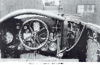
The cockpit and flight controls of Gotha G.V 904/16 are typical for Gotha G.IV bombers as well. The cellon window above the instruments provided illumination during the day.
The way the exhaust exits the starboard side of the fuselage indicates it is an Aviatik-built Halberstadt D.II(Av). (Peter M. Grosz Collection/STDB)
Halberstadt D.II(Av) was originally called the Aviatik D.I until Idflieg rationalized designations. The Aviatik plate was on the nose. The D.II had ailerons with wider chord at the wing tips. The large numerals were applied at the unit. (Peter M. Grosz Collection/STDB)
Техник демонстрирует легкость фюзеляжа "Хальберштадта" D.II.
Halberstadt D.II(Han) 818/16. being admired by the men; the light weight is indicated by the man lifting the tail. The photos of 816/16 and 818/16 show the factory finish of Hannover-built Halberstadt D.ll fighters. Rumpler C.I 2623/16 and Rumpler G.II 122/15 are in the background.
Halberstadt D.II(Han) 818/16. being admired by the men; the light weight is indicated by the man lifting the tail. The photos of 816/16 and 818/16 show the factory finish of Hannover-built Halberstadt D.ll fighters. Rumpler C.I 2623/16 and Rumpler G.II 122/15 are in the background.
Halberstadt D.II(Han) 818/16. The light serial numbers were characteristic of Hannover-built D.II fighters.
Halberstadt D.ll of Pour le Merite holder Ernst von Althaus that he flew with Jasta 4.
Halberstadt D.II purportedly flown by Leutnant Walter Hohndorf of Jasta 14.
Halberstadt D.II purportedly flown by Leutnant Walter Hohndorf of Jasta 14.
Halberstadt D.II supposedly flown by Lt. Walter Hohndorf. The small tube projecting from the cockpit held a flare pistol used for signaling. (Peter M. Grosz Collection/STDB)
Lt. Kurt Wintgens of Jasta 1 with his Halberstadt D.II. The black hole in the cockpit side may have been an opening for a flare pistol. (Peter M. Grosz Collection/STDB)
Halberstadt CLII 5701/17 was part of the first production batch. Here it is unarmed and part of Fliegerhorst Schwerin, a para-military police unit immediately postwar.
Halberstadt Cl.II 1255/18 (w/n 1181) was thoroughly evaluated by the French Section Technique Aeronautique in October-November 1918.
Halberstadt D.V fighters. The gun is to port of centerline. The circular cutout in the trailing edge of the upper wing for increased pilot visibility identifies the aircraft as D.Vs; the D.II and D.III had an angular cutout. The redesigned three-piece upper wing with redesigned cabane section gave better visibility. All these aircraft had an Argus As.II engine. (Peter M. Grosz Collection/STDB)
This Halberstadt D.V in Turkey has additional radiators attached to the fuselage sides in addition to the airfoil radiator. The pilot is Oblt.d.R. Theodor Croneiss, commander of Ottoman Fl. Abt. 6 (Peter M. Grosz Collection/STDB)
Курсовой пулемет был установлен между трубами предохранительной пирамиды, возвышаясь над фюзеляжем, а на ее верхушке крепилось зеркало заднего вида.
This closeup of a camouflaged, mid-production C.II 2731/16 shows the crew and armament. The observer has signal flares mounted in a rack aft of his window and the pilot has a rear-view mirror mounted on the turnover pylon.
This closeup of a camouflaged, mid-production C.II 2731/16 shows the crew and armament. The observer has signal flares mounted in a rack aft of his window and the pilot has a rear-view mirror mounted on the turnover pylon.
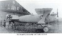
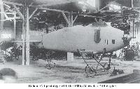
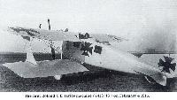
The second Roland D.I prototype
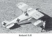
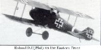
Developed from the earlier Roland C.II two-seater, the Roland D.I fighter had two guns and the 160 hp Mercedes D.III engine. It was fast but the pilots' forward view was poor, and the design was quickly revised as the Roland D.II to fix that limitation, particularly problematic for a fighter.
Developed from the earlier Roland C.II two-seater, the Roland D.I fighter had two guns and the 160 hp Mercedes D.III engine. It was fast but the pilots' forward view was poor, and the design was quickly revised as the Roland D.II to fix that limitation, particularly problematic for a fighter.
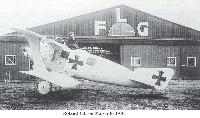
The prototype Roland D.II on Oct. 22, 1916 in front of the LFG flight test hangar. An anemometer airspeed indicator is mounted on the upper left wing.
Jasta 27 lineup; a single Roland D.II is at left in a lineup consisting mostly of Albatros D.III and D.V fighters.
This Roland D.IIa, completed the morning of 7 Feb. 1917, was the 500th Roland airplane built during the war.
19-victory ace Vzfw. Gerhard Fieseler in the cockpit of Lt. Ahelfeld's Roland D.IIa of Jasta 25 in Macedonia. Jasta 25 Roland fighters were normally identified by the initial of the pilot's last name; here, 'A' for Ahelfeld. Fieseler's aircraft would most likely have had an 'F' for identification. After the war Fieseler started his own aircraft company; his most famous product was the Fi-156 Fieseler Storch (Stork) known for its exceptional low speed flying qualities and ability to make very short landings and take-offs.
Dramatic view of a Roland D.IIa in Bulgarian service in 1918 as indicated by the late-style insignia.
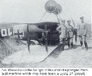
Ltn. Wieland is on the far right of this shot of a pranged Pfalz-built machine which may have been a Jasta 27 aircraft.
LVG C.V 3242/17 probably at Doberitz. Standing before the aeroplane are Rittmeister Prince Friedrich Sigismund (left) and LVG designer Dipl. Ing. Willi Sabersky
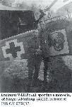
Leutnant Willi Pysall sporting a monocle, of Flieger Abteilung (A) 212, in front of LVG C.V 9751/17.
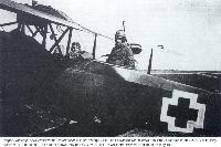
Flieger-Abteilung (A) 252w crewmen Unteroffizier Wilhelm Weniger, pilot, and Leutnant der Reserve Fritz Freit, observer, in an LVG C.V with early summer 1918 markings. The aircraft shown may be LVG C.V 9810/17 in wich the crew were killed on 27 May 1918.
LVG C.V of Flieger Abteilung 25 with painted fuselage. Uffz. Wilhelm Hubner was the pilot. (Greg VanWyngarden)
Pilot Unteroffizier Wilhelm Hubener (right) of FLieger Abteilung 25 in an LVG C.V.
Pilot Unteroffizier Wilhelm Hubener (right) of FLieger Abteilung 25 in an LVG C.V.
Кабина экипажа самолета CV. В кабине летчика только два прибора и ручка управления в виде трезубца. Пулемет "Парабеллум" установлен на оригинальной турели, напоминающей турель Скарфа, но со своеобразной системой фиксации дуги.
The crew of a Rumpler (???) reconnaissance aircraft lie dead beside their aircraft after being brought down.
LVG C.VI 9027/18 (?) work number 4938 photographed at Trier on January 3, 1919. The photo confirms the scheme and shows the camouflage fabric also covered the tailplane. The photo of the rear of the aircraft confirms the care the design team took to minimize frontal area and thus drag.
Pfalz E.I 213/15 was used as a trainer. The designation and serial number are just above the rudder cross.
Lt. Otto Kissenberth with a Pfalz E.I at KEK (Kampfeinsitzer Kommando) Ensisheim. The E.I shows the iron crosses beneath the wings and tailplane. The wing structure shows through the fabric, and the Pfalz logo is on the center of the engine cowling. Kissenberth first became a fighter pilot at KEK Ensisheim and went on to score 20 confirmed victories and win the Pour le Merits before crashing a captured Sopwith Camel. His last victory was in the captured Camel. His injuries kept him out of further combat. Kissenberth was one of a number of aces who wore glasses.
The Pfalz E I was broadly based on the Morane-Saulnier Type H and began to arrive at the Front from late October 1915.
Oblt. Rudolf Berthold crashed in Pfalz E.IV 803/15 at Chateau Vaux aerodrome on 25 April (22 May ???), 1916. The serious injuries Berthold experienced in this crash were the first of many wounds and injuries that finally forced his removal from the front, but not before scoring 44 confirmed victories and being awarded the Pour le Merite.
Leutnant Ernst Udet crashed a Pfalz E.IV when he was attached to the Kampf-Einsitzer-Kommando Habsheim.
Cockpit of Pfalz D.III 4184/17 of Jasta 15 captured on February 26, 1918 and assigned the British captured aircraft number G.141
Pfalz D.III 4185/17 photographed at the Jasta 5 aerodrome at Boistrancourt in 1917. Overall silbergrau finish is relieved by encircling red and white bands which have obliterated all traces of the fuselage serial number. Note windscreen style and safety harness Strap hanging from cockpit.
The best-known of German triplanes after the Fokker Dr.I emerged from the Pfalz factory at Speyer on the Rhine. The design was of typical Pfalz construction; the Wickelrumpf or wrapped-skin fuselage structure was built up on a light framework of stringers by a series of thin three-ply strips and cloth tape. The result, as evidenced in the D.III, was strength but increased weight. The Dr.I was based on the Pfalz D.VII, a relatively unsuccessful product, and was compact and well-proportioned. Powered by a 160 hp Siemens Sh III engine, it began flight tests in August 1917 and recorded the best rate of climb of any German aircraft up to that time, superior to the Fokker Dr.I. Probably three prototypes were built, 3050 and 3051/17 with 3052/17 as a static test.
On 12 December 1917 Manfred von Richthofen left his Geschwader to visit the Pfalz works, accompanied by his technical officer Lt Krefft. Such well-known pilots as Hpt Willy Meyer, von Tutschek and Ernst Schlegel also arrived to evaluate the new types. Von Richthofen was very impressed with the capabilities of the Dr I, and it is probable that as a result of his recommendations the Pfalz was ordered into small-scale production for front-line evaluation. It was further planned to build 100 Dr.I's, and to expose them all along the front simultaneously in January 1918, presumably with the purpose of demoralizing the enemy. This scheme was evidently dropped, for only ten were constructed. Nine went to the front, so presumably one Dr.I was retained at Speyer. Photographs exist of 221 and 222/17, but beyond that there is no record of other production examples or any service details of the nine that reached the front.
The Pfalz Dr.I arrived too late to compete seriously with the Fokker Dr.I and its quicker production techniques. The official reason for its rejection was its slow speed, and indeed this would seem to have been its main disadvantage.
Description: Single seat fighter
Manufacturer: Pfalz Flugzeug-Werke, G.m.b.H. Speyer am Rhein (Pfal.)
Engine: 160 hp Siemens-Halske Sh. III
Dimensions:
Span 8.6 m (28 ft. 1 in.)
Length 5.6 m. (18 ft. 1 in.)
Height 2.9 m. (9 ft. 1 in.)
Area 17.2 sq m. (186 sq. ft.)
Weights:
Empty 498 kg (1,122 lbs)
Loaded 704 kg (1,551 lbs)
Performance:
Climb to
1,000 m 1 min 12 secs
2,000 m 3 mins 12 secs
3,000 m 5 mins 24 secs
4,000 m 7 mins 48 secs
5,000 m 10 mins 48 secs
6,000 m 14 mins
Ceiling 6,500 m ( 21,325 ft)
Endurance 1 1/2 hrs
Armament: Twin Spandau machine-guns
Serials Prototypes: Dr 13050/17, 3051/17
Production: Dr 1221/17, 222/17. Five more examples built
Pfalz Dr.I (3050/17), was flight tested by von Richthofen and Tutschek at the Pfalz factory in Speyer during October of 1917.
Pfalz D.XII 1460/18 in Allied hands after the war, 6 January 1919. Black and white stripes painted in spanwise manner on the tailplane and rear fuselage (not visible in this view) provide evidence that this Pfalz once served in Jasta 23b. In the background are piles of Albatros fighter fuselages turned over in accordance with the Armistice specifications
Один из последних "пфальцев" D.XII, собранных в конце войны. Эта машина не успела попасть на фронт и в числе других была выдана французам по условиям компьеньского мирного соглашения.
Hans Röttges, Flugtechniker, Bremen
"Carré". Tandem triplane with 30 hp Palous & Beuse engine. Built by Pega & Emich in 1910. Unable to fly.
Zeitschrift Flugsport: Jahrgang 1910:
Летательный аппарат Röttges-Carre. Hans Röttges из Бремена сконструировал летательный аппарат, существенно отличающийся от всех предыдущих конструкций расположением несущих поверхностей. Машина, показанная на изображениях, была построена компанией Pega-Emich-Sommer в Griesheini и в настоящее время используется на плацу Griesheimer недалеко от Франкфурта. Аппарат полностью изготовлен из стальных труб, сваренных автогенной сваркой. Размах 8 м, общая длина 13,5 м, вес с направляющей 400 кг. Для работы используется двигатель Palous & Beuse мощностью 30 л.с. Шасси состоит из 4-х колес, передние из которых являются управляемыми. Винт Шовьера приводится в движение цепью Галля и расположен за первым крылом. Площадь крыльев составляет 57 квадратных метров.
Пилот Strack попытался совершить полет на лугах Pulverwege недалеко от Дуйсбурга, и поначалу все прошло очень хорошо. Воодушевленный этим, Strack поднялся на высоту до 60 м и сделал несколько витков. Во время снижения пилот попытался планировать, но так сильно ударился о землю, что аппарат был поврежден.
Техник демонстрирует легкость фюзеляжа "Хальберштадта" D.II.
Halberstadt D.II(Han) 818/16. being admired by the men; the light weight is indicated by the man lifting the tail. The photos of 816/16 and 818/16 show the factory finish of Hannover-built Halberstadt D.ll fighters. Rumpler C.I 2623/16 and Rumpler G.II 122/15 are in the background.
Halberstadt D.II(Han) 818/16. being admired by the men; the light weight is indicated by the man lifting the tail. The photos of 816/16 and 818/16 show the factory finish of Hannover-built Halberstadt D.ll fighters. Rumpler C.I 2623/16 and Rumpler G.II 122/15 are in the background.
Под верхним крылом самолета устанавливался радиатор в полукруглом туннеле с регулирующей заслонкой впереди.
Второй серийный экземпляр SSW D.III на заводском аэродроме.
The D III, the photo depicting a first series aircraft in February 1918.
The D III, the photo depicting a first series aircraft in February 1918.
SSW D.III из эскадрильи Kest 5, август 1918 г.
SSW D.III 1620/18 at Siemensstadt, showing final form of cowling, spinner, ailerons, and rudder. Wing and rudder crosses have been over-painted in 6:5 proportions.
SSW D.III 1620/18 at Siemensstadt, showing final form of cowling, spinner, ailerons, and rudder. Wing and rudder crosses have been over-painted in 6:5 proportions.
SSW D.III of Lt.d.R. Alfred Greven of Jasta 12. The cowling is not standard and there is no spinner. The white lightning bolt was Greven's personal marking. Greven scored two confirmed victories in September 1918 and two more in October for a total of four.
Ltn. Vallendor's SSW D.III, Jasta 15.
SSW D.III probably serving with a Kest. It was a first series D.III, which means it could have been assigned to Kest 4b (Freiburg), Kest 5 (Lahr), Kest 6 (Bonn), or Kest 8 (Bitsch), but the Kest 4b lineup photo does not show it.
SSW D.III probably serving with a Kest. It was a first series D.III, which means it could have been assigned to Kest 4b (Freiburg), Kest 5 (Lahr), Kest 6 (Bonn), or Kest 8 (Bitsch), but the Kest 4b lineup photo does not show it.
SSW D.IV 3082/18. The SSW D.IV was derived from the D.III by replacing the top wing with one of narrower chord; the greater aspect ratio reduced drag, increasing speed and climb rate.The D.IV had the highest climb rate and ceiling of all WWI operational fighters. (1918)
The D IV attained operational service in small quantities from August 1918.
The D IV attained operational service in small quantities from August 1918.
The cockpit of SSW D.III D.8341/17 in its original form. The SSW-designed control column was used only on first series machines. It was replaced on later and rebuilt D.IIIs with SSW's version of the Fokker Steuerangriff dictated by Idflieg.
Paul Winkler, Schlesien
Monoplane with 30 hp Weiland & Gildemeyer engine. 1910. Unsuccesful.
Monoplane with 30 hp Weiland & Gildemeyer engine. 1910. Unsuccesful.
Пилотская кабина R VI. Широкие окна предоставляли хороший обзор. Впереди виден лаз в носовую открытую площадку, на которой размещалась пулеметная установка.
Type B.D.F. is a Burgess Dunne boat.
Model Flying Boat.
Type B.D.F.
Length 25'2''
Span 53'
Useful load, lbs. 560
Motor, h.p. 100 Curtiss Oxx2
Fuel capacity 3 hours
Speed, Max 68
Speed, Min 43
Seating capacity 3
Model Flying Boat.
Type B.D.F.
Length 25'2''
Span 53'
Useful load, lbs. 560
Motor, h.p. 100 Curtiss Oxx2
Fuel capacity 3 hours
Speed, Max 68
Speed, Min 43
Seating capacity 3
Breguet 14 A2 of BR 209 which was assigned to the 3rd Armee. The escadrille's insignia was a cockatoo
Breguet 14 A2 of BR 220. Pilot is Serrant, observer Dreyfus. The machine gun mounted on the top wing is a field modification
Another view of Breguet 14 A2 Jane IV piloted by Mal des Logis Jean Charles Pavy and Lieutenant Hardy of BR 209 in 1917. BR 209 was active over Noyon and Saint Quentin.
Breguet 14 B1 intended for Jules Vedrine's proposed raid on Berlin. However, the aircraft's range proved to be too marginal for the task and the raid was canceled
Breguet 14 B2 serial BR 1102 with Michelin bomb racks underneath the wings. This is an early Michelin-built machine. The fuselage windows are lower on the fuselage than on later machines
Breguet 14 B2 serial 12079 of BR 123 showing a full complement of 50-kg and 75-kg bombs. The crewmen are identified as the Peyerimhoff brothers. This aircraft was built by Michelin
Breguet 14 B2 serial BR 13005 of BR 134. The observer's windows were on either side of his cockpit. This late Michelin-built machine lacks the trailing-edge flaps on the lower wing. The engine is a Liberty
Caudron G.4 of C 66 at Fretoy in 1917. C 66 was formed (along with N 65) from G.C. Malzeville in late 1915 and was assigned to GB 2 at Malzeville.
A 1915 type, the Caudron G.4 remained in service long after it was obsolete.
A 1915 type, the Caudron G.4 remained in service long after it was obsolete.
Caudron G.4 C212. This airplane served as a target tow plane for the Ecole Tir de Chasse at Biscarrosse.
Caudron G.4 of C 30. This unit participated in the Somme offensive in July 1916 where it performed bombing missions.
Caudron G.4 in Belgian service. The Franco-Belgian Squadron No.674 had both French and Belgian pilots. It was equipped with Caudron G.4s. Colin Owers.
A French Caudron G.IV. Aircraft of this type equipped several of the corps escadrilles attached to the French VI Armee in April 1917
HD.1 in service with the Belgian air force. The Aeronautique Militaire Belge ordered 79 Hanriot HD.1s in 1917
Production of the HD.1 was undertaken by Hanriot only to meet orders from Belgium.
Production of the HD.1 was undertaken by Hanriot only to meet orders from Belgium.
Morane-Saulnier Type N, probably at the Morane-Saulnier factory. The airscrew is armored and the aircraft is armed with a single Hotchkiss machine-gun
A Nieuport 10 N237 in French Service. French Nieuports usually did not carry roundels on the fuselage
This Nieuport 10 single seater, wearing French colors, carries the number 237 on the rudder. The V struts can be seen between the upper and lower wing. Armament is a single, centrally mounted, overwing Lewis gun
237 has a French roundel painted on the fuselage side, highly unusual for a French aircraft. Another Nie.10 stands in the background
A carry over from the days of the two seater, the Nieuport 10 has the characteristic look of an elongated two seater fuselage
Первый невооруженный прототип "Ньюпора-11" с французскими военными эмблемами, 1915 г. The unarmed and unnumbered Nieuport 11 prototype. The elevators were smaller than those which would later become standard and the spread of the undercarriage V braces are somenhat greater here. The rear center section struts just in front of the cockpit are an inverted 'U' shape, probably to improve the view from the cockpit. The national markings are French
It is unclear what national markings this Nie.11 carries, but interestingly the aircraft armed with twin machine guns. The wheel discs are believed to have been red
One of several Nie.11s that fell into German hands and were test flown. The armament has been removed and a small cone de penetration has been added to the airscrew boss. The extreme inboard position of the national markings under the lower wing is unusual
Repainted with national insignia of its captors, this Nie.11 has had its armament removed. Other Nieuports which fell into Austrian hands were often renumbered and flown in action
Nieuport 11, probably Italian-built, after capture by Austro-Hungarian forces and bearing the Austro-Hungarian serial 00.27
Французский истребитель "Ньюпор-16" с ракетами Ле-Прие / The rocket armed N959 in German hands. The ornate letter 'R' on the fuselage side of N959 was the insignia of the pilot flying it at the time of its capture, Adjutant Henri Reserval. This machine was later test flown by a number of German pilots
By 1916 French air strength had become impressive, and with types such as the Nieuport and Spad the fighter units had capable equipment. The Nieuport 17, as N2474 here, was powered by a 110hp Le Rhone and had a top speed of 110mph (177kph).
Nieuport 17, possibly of Escadrille N76. This Nieuport was built in large numbers and equipped many of the French fighter squadrons, as well as a variety of Allied units.
The triangular fanion on the fuselage of N1932 is the light blue and gold emblem of Escadrille N76. The colors were also used for the zig-zag on the rear fuselage. A personal marking which is possibly medium blue aft, extends over the decking
The triangular fanion on the fuselage of N1932 is the light blue and gold emblem of Escadrille N76. The colors were also used for the zig-zag on the rear fuselage. A personal marking which is possibly medium blue aft, extends over the decking
The insignia of Escadrille N48, the head of a crowing cock can just barely be seen on the fuselage side of this Nie.17 number 1930
This Nie.17 numbered N2038 belonging to Escadrille N15 was named DEDETTE III and carried an elaborate helmet and plume in front of the numeral 7
A Nie.17, one of the single seat trainers used by a United States' flying training school in France, hence the retention of the tricolor roundels
Operated by Czarist Russia while wearing French colors, this machine was captured by the Germans. Its identity may have been N3389
The RFC's Nieuport triplane, presumably still at Candas and apparently before the finishing touches were put to the painting of its RFC serial number A6686
A6686 was tested at Martlesham Heath in April 1917 where this photograph was taken; the test report was anything but flattering
A view of a Nieuport Nie.25 with Nungesser in the cockpit. The onlookers appear to be Belgian officers.
A refined development of the Nieuport 28 existed in prototype form
The Nieuport monocoque fighter was tested early in 1918, but had been abandoned by April.
The Nieuport monocoque fighter was tested early in 1918, but had been abandoned by April.
Nieuport 200-hp Clerget 11E. This aircraft, which was in many respects similar to the Nieuport 28, had a marked positive stagger to the upper wings.
Sometimes mistaken, even by French writers, for the Nieuport 28, this later development of November/December 1917 had the 200 hp Clerget 11E engine
Sometimes mistaken, even by French writers, for the Nieuport 28, this later development of November/December 1917 had the 200 hp Clerget 11E engine
At least two aircraft were built with diedre total (full dihedral) on the upper wing. One of these bore the SFA serial number N4434
1/Lt. James Meissner's Nieuport N6144 following the incident in which its upper wing fabric tore away on May 2 1918
The sober looking 1/Lt. James Meissner stands beside N6144 after losing upper wing fabric on May 2 1918
1/Lts. Eddie Rickenbacker, Douglas Campbell and 1/Lt. Kenneth Marr before a white-cowled Nieuport 28 of Rickenbacker's flight which may well be his own N6154
Members of the 27th Aero Sqdn. beside Nieuport 28 No.2, assigned to 1/Lt. Leo H Dawson at Toul in early June 1918
27th Aero Squadron's 'A' Flight at Saints aerodrome, August 1 1918, about 25 minutes before the patrol in which six members of the squadron were lost
A Nieuport 28 (or in French designation, XXVIIIC.1) fuselage is shown here without armament. In March, because guns had not yes supplied, the 95th and 94th Squadron pilots went over the lines in limited sorties near Villeneuve
Salmson 2 A2 of SAL 32. The escadrille was assigned to the 10th C.A. and was initially based at Montdidier
Paul Schmitt on an airfield near Dunkerque. These appear to have wing-mounted Lewis guns and include serial numbers 23 and 24
Paul Schmitt P.S.7. In most respects the Type 7 was identical to the Type 6; however, the lower wing of the Type 7 was attached directly to the fuselage.
Spad A-2, serial S.19 of an unidentified French unit, carried the name "MA JEANNE" (My Jean) on the fuselage side in Black
A Ukrainian (formerly Russian) biplane of the Spad biplane type, with the airscrew in the middle of the body. Note should be taken of the special skids for running on snow. The unenviable position of the gunner in front of the propeller is clearly illustrated!
French-built Spad A.2 fighter fitted with skis, winter 1916. Kokorin flew this type of aircraft during fall 1916. Armament was a Lewis machine gun mounted in the front observer/gunner's pulpit.
French-built Spad A.2 fighter fitted with skis, winter 1916. Kokorin flew this type of aircraft during fall 1916. Armament was a Lewis machine gun mounted in the front observer/gunner's pulpit.
The Russians flew the Spad A.2 and its sucessor the Spad A.4 long after the French had retired them - chiefly because there was a chronic shortage of aircraft within the Russian Air Service. This aircraft (serial S.79) is armed with a .303 Lewis machine gun
This Spad A-2 of the imperial Russian Air Service was equipped with skis for operations from snow covered airfields
This Spad 7 (serial S.1379) carries the Black Dragon of Spa.65 on the fuselage and is believed to have been flown by ADJ Marcel Henriot
This aircraft is believed to be the Spad V, prototype for the production Spad 7. The aircraft lacks national markings, has short individual exhaust stubs, and a smaller windscreen than production Spad 7s
This Spad 7 was experimentally equipped with a 150 hp Renault engine which required extensive modifications to the aircraft's nose in order to accomodate the 60 angle of the engine's cylinder banks, The engine was not selected for production Spad 7s
This Spad 7 (S.111) was the first aircraft off the production line. The aircraft was later modified with a wide radiator cowling opening. A collector pipe was fitted to the engine exhaust stubs
An early production Spad 7 (serial S.1837) on the airfield at Bar-le-Duc. The standard color scheme for early Spad 7s was overall clear dope on the fabric surfaces with the metal cowl panels painted Light Yellow to roughly match the doped fabric. The Yellow painted area extended to just behind the cockpit
This early Spad 7 reveals the single Vickers machine gun, wrap-around windscreen, and early cowling opening. The two teardrop shaped fairings are the covers for the engine cylinder heads and the fairing between the upper wing and the fuselage covered the gravity fuel tank and radiator header tank piping
During cold weather, early Spad 7s experienced problems keeping the engines warm enough. A number of field modifications were tried to correct this problem including fitting the radiator with a solid metal cover, such as on this Spad 7
The small cowling opening of the Spad 7 caused engine cooling problems during warmer weather. Eventually the opening was enlarged, however, before this was done a number of field modifications were tried, including drilling extra cooling holes in the cowling as on this Spad 7
Le Grand Chasseur, LT Georges Guynemer, the best known French ace of the war beside his first Spad 7 (S.113). This was the first of three Spad 7s flown by Guynemer, all of which carried the name Vieux Chales on the fuselage. The Stork marking of Escadrille Spa.3 was in Red with White details
CAPT Georges Guynemer in his third Spad 7 (serial S.254) on 25 May 1917. This aircraft was the first Spad 7 powered by the 180 hp Hispano-Suiza to be sent to the front. Guynemer gained nineteen of his fifty-four victories with this aircraft, which still exists. It was recently restored by the Musee de l'Air for display at Le Bourget
During 1976 Guynemer's Spad 7 (S.254) was displayed at the Armee de l'Air Academy at Salon-de-Provence. The aircraft was hung indoors, however, there was no attempt to restore the Spad until 1981, when it was turned over to the Musee de l'Air and completely restored
This Spad 7 belonged to an unidentified French pilot who wanted no one to mistake his nationality. The aircraft carries French roundels on the fuselage, wings, and horizontal tail plane. Additionally, he had broad Red, White and Blue stripes painted on the fuselage sides. The reason for this was to avoid possible confusion with German Albatros D.I and D.II Fighters
S.154 also carried tri-color stripes on the rear fuselage. The starboard section of the windscreen has been removed, a practice that was often done on the Spad 7 to provide easier access to the gun breech to clear jammed rounds. THis aircraft also carried roundels on the tailplane
This Spad 7 (S.239) of Spa.102 at Courbeaulieu during March of 1917 has the engine cowling access panels removed for maintenance. The fin has been painted a dark color and carries a personal marking, possibly consisting of the pilot's initials
LT Frederic Loiseau of N 561 in his Spad 7 (S.1068) at Lido airfield. The nose of this aircraft was White and the area around the cockpit is believed to have been Green, with a shield-like marking bearing Loiseau's initials. The charging Black elephant on the fuselage side was also a personal marking
Spad 7s from various Escadrilles de Chasse on the airfield at Ham. The Spad in the foreground is assigned to Spa.31, while immediately behind it is an aircraft belonging to Spa.48
This Spad 7, fitted with a non-standard windscreen, carries no armament and is believed to have been used as a training aircraft. The marking on the fuselage is believed to be a personal insignia
Ground crews bore-sight the Vickers machine gun of a Spad 7 into a hillside firing pit at a French airfield on the Marne during April of 1917
An RAF ground crewman demonstrates the use of a Hucks starter truck to start the engine of this Italian Spad 7. The British demonstrated the Hucks starter to the Italian during the mid-1920s
This Spad 7 of an unknown Italian unit carries an inscription on the fuselage side which reads T veclo...!!! (old man in the Venetian dialect). The fighter in the background is an Ansaldo S.V.A.5
LT Rudolf Windisch of Jasta 66 in the cockpit of a captured Spad 7. LT Windisch flew the Spad in combat with German markings, however, he retained the dragon marking and tri-color wing stripes of its former owners, Escadrille Spa.65, on the fuselage side
This Spad 7 was one of a number of Spads that were exported to Czechoslovakia. The aircraft served with the Czechoslovakian Air Force during 1920 and had the landing gear struts faired over in an attempt to increase the aircraft's top speed
Rene Fonk's Spad VII (S1461) with the Spa 103 'Stork' and the Roman IX number. Forced landing in May 1917
This crashed Spad 7 is believed to have been assigned to Escadrille Spa.67. The aircraft has a pair of eyes painted on the cylinder head fairings. The large square and circular cutouts in the fuselage engine access panels were done to provide additional cooling air to the engine
This Spad 12 was flown by the commanding officer of the 13th Aero Squadron, United States Air Service, MAJ Charles J. Biddle
After the Spad 12 was delivered to Guynemer, he added the name Vieux Chales and a diagonal White stripe to the fuselage sides. The individual aircraft number, 2, was in Black
Georges Guynemer in the deep cockpit of the first Spad 12 (S.382). Guynemer personally conducted much of the flight testing on the Spad 12
Guynemer displays his avion magique to General Francet d'Esperey at La Bonne Maison on 5 July 1917. Earlier that day, Guynemer had flown the first combat mission with the Spad 12, during which the aircraft was damaged. The wings of S.382 have been removed, pending its transport to Buc for repairs
An early Spad 12 (S.434) parked on a French airfield. Most units had one or two Spad 12s assigned to them, with instructions to allow the best pilots in the unit to fly the aircraft. This Spad 12 is believed to have been painted overall Light Grey
This Spad 12 (S.440) reveals the plywood pocket extensions that were fitted to the wing tips trailing edges of Spad 12s to square off the wings. Later, new wings incorporating square tips were introduced onto the production line
The other Spad 12 assigned to Fonck was S.445. Fonck's personal number, VI, was carried on the rear fuselage and repeated on the port upper wing surface in Red, outlined in White. The White-outlined Red star on the starboard wing was the former unit insignia of Spa.103
Spad 12s were progressively modified during production with new engines and other improvements. This late Spad 12 is powered by a 220 hp Hispano-Suiza 8Bc engine and has the louvered engine access panels removed for maintenance
This camouflaged late production Spad 12 has been modified with squared off wings tips. The Vickers machine gun on the Spad 12 was offset much further to starboard than the gun on the earlier Spad 7
Two Spad 12s (foreground) share the field with five Spad 7s, at Reserve Generale de l'Aviation (RGA) airfield while awaiting delivery to French Escadrilles de Chasse. The two aircrafts carry different color schemes; the aircraft on the left is painted an overall dark color, while the aircraft on the right has been camouflaged
A Bleriot-built Spad 13 of Spa.81 carries the running Greyhound squadron insignia. It was flown by ADJ Marius Blanc
This early Spad 13 is believed to have been one of the twenty pre-production aircraft built during early 1917. These aircraft had a more tapered engine cowling than the Spad 12 and also reintroduced the teardrop-shaped cylinder bank fairings, similar to those used on the Spad 7
Among the first French aces to fly the Spad 13 in combat was Guynemer, who was assigned Spad 13 (S.504) in September of 1917. Guynemer was lost flying this aircraft on 11 September. S.504 bears the Stork insignia of Spa.3 (White with Black wings) and Guynemer's personal number, 2 on the fuselage side, however, it did not carry the name Vieux Charles
This Spad 13 (S.512), one of the first twenty pre-production aircraft built, was used for official tests by the Section Technique del'Aeronautique at Villacoubly from March through September of 1917
This Spad 13 (S.1893), flown by ADJ Jacques Roques of Spa.48, carries the later form of the unit's Fighting Cock insignia. The radiator cowling and the arc around the insignia are Blue, while Roqies' personal number, 7, is in Red
This early Spad 13 (S.1929) reveals the rounded wing tips that were common on early production Spad 13s. An unusual feature of this particular Spad 13 is that all the wing ribs have been taped. This aircraft also has a rear-view mirror on the upper wing center section
This Bleriot-built Spad 13 (S.2179) is believed to have been assigned to Escadrille N 561 based at Lido Aerodrome, near Venice, Italy. Pilot in the cockpit is thought to be Xavier Garros
Components for at least two Spad 13s, including S.7542, prepare to leave the Kellner production plant. The aircraft were shipped by truck to a reassembly RGA where they were delivered to French fighter units
This Spad at Thionville during 1923, the last year the Spad served with French military aviation. By this time most of the Spads that remained in service were being used as advanced training aircraft
Marechal des Logis Rene de Liniere alongside his Spad 13 of Spa.103. Spa.103 was part of the Allied Occupational Forces at Neustadt, Germany during the Spring of 1919. The Spad in the foreground is thought to be a Kellner-built aircraft fitted with a non-standard windscreen
Spads of Spa.68 are neatly lined up on a French airfield. The two aircraft in the background is a Spad 7. The French horn on the fuselage side is the unit insignia for Spa.68. The horn and the individual aircraft number are repeated on the upper wing surface
Jean Lucas alongside a late production Spad 13 of Spa.97. The wooden fairing around the drag wire which runs from the top of the forward cabane strut to the top of the fuselage has the appearance of an additional strut. The individual number, 12, in White on the fuselage side was also repeated on the upper starboard wing
This Spad 13 was assigned to Spa.84, which was also part of the French Occupational Forces stationed in Germany during 1919
ADJ Marius Blanc in the cockpit of his Spad 13. Blanc was assigned to Spa.81, Fighting Greyhounds. The Greyhound insignia was one of the most attractive unit insignias used by French forces during the war
French officers prepare a Bernard-built Spad 13 for a demonstration flight in Japan. The Spad was part of the French Aeronautical Mission to Japan during 1919. The following year, the Japanese Army Air Force adopted the Spad 13 as its standard fighter under the designation Hei 1
The pilot of this early Spad 13 assigned to Spa.3 waits while a ground crewman checks the guns before starting the engine. The pilot at the extreme left is believed to be Guynemer
This late production Spad 13, believed to have been assigned to Spa.89, was brought down intact by LT Albert Hausmann of Jasta 13 in August of 1918. The aircraft was repainted in German markings and was test flown by Jasta 13
S.P.A.D., along with eight different subcontractors were involved in the production of the Spad 13. The aircraft factories of that period appear very primitive when compared with a modern aero-space plant. It is difficult to believe that thousands of Spads were built under such conditions
CAPT Robert Soubiran standing next to his Spad 13 (S.7714) of the 103rd Aero Squadron (formerly the Lafayette Escadrille). The Indian head unit marking was framed by a White-outlined Red diamond. The diamond was repeated on the horizontal tailplane, but without the White outline, and a tri-color stripe was added to the fuselage and radiator cowling
This Kellner-built Spad 13 (S.16541) was flown by MAJ Robert L. Walsh of the 22nd Aero Squadron, USAS. The fuselage number was Red, outlined in White, and the radiator cowling was Blue. This aircraft was a companion to the one which is now in the National Air and Space Museum in Washington
CAPT Edward V (Eddie) Rickenbacker, America's leading ace, in the cockpit of his Spad 13 (S.4523) of the 94th Aero Squadron. The Hat-in-the-Ring unit marking was carried on both sides of the fuselage along with a White numeral 1 outlined in Red, which was repeated on the starboard upper wing surface. Rickenbacker scored twenty-one of his twenty-six victories in this aircraft
This Spad 13 served with the 2nd Air Regiment of the Czechoslovakian Air Force during 1925. The national insignia under the wing is a representation of the Czech flag
This photo from an instruction manual shows the SPAD 13 armament from rear. Ammunition was fed from boxes below and inside the fuselage. Gun cocking handles are just forward of the windshield. Ammunition gave serious problems with belts sticking and poor cartridge sizing, conditions which could not be fixed in flight
На S.7 патроны снаряжались в матерчатую ленту, которая наматывалась на барабан. Питание пулеметов "Виккерс" на S.13 сделано по "британской" схеме - с металлической составной патронной лентой. Патронная коробка с этими лентами находится между пулеметами. (Front view of the Vickers machine guns on SPAD 13 with engine cowling removed. Vibrations from recoil, coupled with other shocks from poorly operating engines created fuel and oil pipe leaks in nearly every flight. Constant checking and fine-tuning of the Hispano-Suiza engines, and replacement of pipeage, oil and fuel tanks was required)
Voisin 5
The Voisin 3 had proved a successful bomber, but its payload was limited by the Salmson M9 engine, which produced only 120-hp. The Aviation Militaire wished to obtain a more powerful airplane but with the concours puissant (competition for a heavy bomber) not due to take place until mid-1915, it was decided to produce a Voisin 3 with a new engine. A Voisin 3 airframe was fitted with a 150-hp Salmson P9 engine, and the airframe was strengthened and the central nacelle streamlined. The new engine was placed on a raised platform to provide clearance for the propeller and was angled to provide downward thrust. The landing gear was strengthened and the wing chord was increased from the roots to the wing tips. The new aircraft was given the STAe designation Voisin 5, while the factory designation was LAS. The S stood for sureleve (raised) which indicated the raised engine mount. While the exhaust system on the Voisin 3 permitted fumes to escape freely, that of the Voisin 5 ejected the fumes upward through two exhaust pipes.
One Voisin 5 was transformed into a twin-engine aircraft in 1916. This was accomplished by adding a second Salmson in the front of the fuselage driving a tractor propeller. it is believed this was done to test a possible configuration for a new bomber planned by Voisin. The twin-engine Voisin 5 first flew in early 1916; apparently the type was not developed further.
The first Voisin 5 reached VB 101 in 1915 and soon replaced the Voisin 3 on the production lines. However, the Voisins 150hp (as they were referred to at the front) were held in low regard by their crews. Despite the more powerful engine, the Voisin 5s' payload was only marginally better and the maximum speed was only 13 km/h faster. Approximately 300 Voisin 5s were built, and these served alongside the Voisin 3s in front-line escadrilles during 1915 and well into 1916.
Voisin 5 (LB) Voisin 5 (LBS) Voisin 5
Two-Seat Bomber Two-Seat Reconnaissance Two-Seat Cannon-Armed Fighter
150-hp Salmson P9 160-hp Salmson 225-hp Salmson built in Russia
Built in Russia
Span 14.74 m 15.70 m 18.80 m
Length 10.28 m 9.5 m 11.0 m
Height 3.80 m 2.95 m 2.95 m
Wing area 45 sq. m 47.00 sq.m 63.00 sq. m
Weights:
Empty 1,000 kg (970 kg) 975 kg 1315 kg
Loaded 1,450 kg (1,370 kg) 1,325 kg 1,865 kg
Bomb load 180 kg
Performance:
Max speed 109 km/h at 2,000 m 105 km/h at 2,000 m 120 km/h at 2,000 m
climb to
1,000 m 10 minutes 9 minutes
2,000 m 22 minutes 22 minutes 20 minutes
3,000 m 40 minutes 36 minutes
Ceiling 3,500 m 4,000 m
Endurance 4 hours 4 hours 2.8 hours
Вид на кабину экипажа Вуазена LA. Пилот самолета сидит под треногой с пулеметом "Кольт". В задней кабине летчик-наблюдатель держит пару авиабомб. Позади него возвышаются короба водорадиаторов.
Voisin 5. This aircraft was a Voisin 3 airframe fitted with a 150-hp Salmson P9 engine, a streamlined nacelle, strengthened landing gear, and a wing chord which increased from the roots to the wing tips.

