
Книги
Журнал
Flight за 1918 г.
479
Журнал - Flight за 1918 г.
Flight, May 23, 1918.
THE AUSTRIAN BERG SINGLE-SEATER FIGHTER.
200 H.P. AUSTRO-DAIMLER ENGINE.
[While the different types of aeroplanes produced in Germany are fairly well known in this country, owing chiefly to the number of them that have been captured from time to time, our knowledge of the Austrian aircraft industry is more limited. This is partly due to the fact that fewer of them are seen on the western front, Austrian activities in the air being more particularly confined to the Italian theatre of war, where the various types of Austrian machines are probably as well known as are the German on the battle front in France. Also it should be remembered that to a large extent, so far as our knowledge goes, the Austrian industry has been conducted more along the lines of constructing German-designed machines under licence, thus tending to increase output, rather than with an aim to encouraging original design. That home designing has not been altogether stopped in Austria is evident, however, since from time to time one hears of Austrian machines, of makes known not to be German licence productions, being seen by Allied pilots. Among these is the Austrian Berg single-seater fighter. Reports have been received occasionally of this machine, but up to the present nothing definite has been generally known concerning it. Now, however, one of these has been added to the collection in the Enemy Aircraft View Rooms, and by the courtesy of the authorities we are able this week to publish a brief description and an illustration of the Austrian Berg. To the best of our knowledge this is the first description to be published in this country.-ED.]
SIMPLICITY would appear to be the keynote of design in the Austrian Berg single-seater fighter, both as regards mass, or aerodynamic, design and structural design. The machine has every appearance of being designed chiefly with a view to rapidity of production, yet this object has been attained by a studied simplicity of detail rather than by any scamping in workmanship. In fact, although the finish is not, perhaps, as good as on some machines, the workmanship appears everywhere to be really quite good, and the materials employed in the construction are, if anything, better than found on a good many German machines. Whether this is due to a more plentiful supply of the right materials in Austria than in Germany, or whether Austrian inspection is stricter than that obtaining in Germany, is difficult to say; and one can only call attention to the fact without venturing an explanation.
Fundamentally the Austrian Berg is of the single-seater fighter type in which the pilot and top plane are so placed in relation to each other that the wing obstructs the view to a very small extent only. This has been accomplished, not so much by reducing the gap to a smaller proportion of the chord than usual, as by making the body very deep and placing the pilot fairly high inside the body. On closer examination it is found that the extra depth of the body is provided by deepening the turtle back, which forms a much greater proportion of the overall depth than is the case in most machines.
The body proper, which is of the flat-sided variety, is constructed on similar lines to those of the older models of Albatros biplanes, i.e., of longerons and struts of fairly small section, the whole being covered with three-ply wood. As distinct from the Albatros, however, there are only four longerons, the auxiliary rails halfway up the sides of the latter having evidently been deemed unnecessary by the designer of the Berg. The turtle back, which is different from the majority in that it does not, except in front, cover the whole width of the flat top of the body, but comes to a point just in front of the vertical fin, is of a peculiar section. This may, in the absence of a sketch, best be described by saying that it consists of three curvatures, a convex at the top, a concave halfway down, and again a convex at the bottom. The object, evidently, is to provide stream lining of the pilot's head by having the turtle back deep without, however, obstructing the view to too great an extent by having it very wide. Roughly the configuration is that of a man's head and shoulders.
The pilot's cockpit is very comfortable, the deep top efficiently screening his face while at the same time, owing to the peculiar outline, not obstructing the view to as great an extent as one would imagine. By leaning his head slightly the pilot can easily look past the nose of the machine, so that there is really no "blind" spot beyond a few yards ahead of the machine. The fact that the chord line of the upper wing if projected passes through the pilot's line of vision renders the view forward and upward particularly good. Small circular windows are inserted in the turtle back in front of the pilot, but it appears that the view obtainable through these is of very little practical utility, and the inference is that they are placed there to admit light on to the instrument board rather than to provide direct vision.
The pilot's seat is extremely comfortable, and is provided with arm rests, thus enabling the pilot to rest one arm while working the control lever with the other. For a long flight this makes for comfort. It is only a minor point, it is true, but one nevertheless which is worthy of consideration. On the whole the machine gives the impression that it would be a very comfortable machine to fly, regarded purely from the flying point of view, and without knowing anything about its capabilities as used for fighting.
The controls are more or less of the usual type. There is a longitudinal rocking shaft, mounted rather higher above the floor boards than is generally the case. The control lever is forked around this shaft, and is free to oscillate forward and backward for operating the elevator. A short length of cable passes from the lower end of the "joystick" to a point on the floor boards. This limits the extent to which the lower end of the lever can move back, and has the effect of preventing, when on the ground, the elevators from touching and getting damaged. In connection with the lateral controls, the wing flaps are fitted with cranks resting in slots in the planes, and there is a somewhat unusual arrangement whereby the positive cable is taken to the front arm of the crank, so that it is the return cable which pulls the wing flap down. The reason for this may be found in the warped wing flap, which may conceivably have its outer tip tilted upwards to such an extent that the effect of moving the flaps is to put a force acting downward on the flap moved upwards before the flap on the opposite side, which has, of course, been moved down simultaneously, receives an upward force. To bring this peculiar action about the crank on the rocking shaft points downwards instead of, as is more usually the case, pointing upwards.
The foot bar operating the rudder is of the T type. That is to say, the rudder control cables are attached to a crank arm projecting forward at right angles to the foot bar. The cables are then taken around pulleys near the side of the body, and hence to the rudder cranks. The guards on the rudder bar, which prevent the accidental slipping off of the pilot's feet, are in the form of spiral springs, each composed of two layers, an inner spiral of fairly thin wire, and an outer spiral of heavier wire.
The engine, which, we are informed, was a 200 h.p. Austro-Daimler, is not shown in place on the machine, but it would appear to have been totally covered in by a deep engine housing. It is mounted on two spruce bearers, each made up of three laminations, mounted on four transverse partitions. These are made up of a spruce centre with facings of three-ply. The armament appears to have been made up of two machine guns, one on each side of the engine, and fitted with the usual interrupter gear.
The wings, which are both of equal span, present nothing out of the ordinary as regards their construction, except that some of the fittings for the internal wire bracing and compression tubes are exceptionally neat in conception and well carried out. Aerodynamically, however, the wings present an interesting feature. The upper surface of the wing section has a most decided return sweep, beginning behind the rear spar and being of such a magnitude as to present a considerable area of concave surface.
The undercarriage of the Berg is not in place on the machine as exhibited, but from fragments it is judged to have been of the Vee type, and in the accompanying illustration we have endeavoured to reconstruct it approximately as various considerations indicate that it must have been.
The tail planes are built of steel tubing throughout, and the fixed tail plane is chiefly remarkable on account of the fact that, although it is built up of single steel tubes, the section is made cambered by bending the single tubes forming the ribs. Both upper and lower surfaces, therefore, have the same camber. The incidence of the tail plane is adjustable, but not during flight.
Later, as opportunity occurs, we hope to be able to publish some illustrations of the more important constructional details of the Austrian Berg fighter.
Flight, October 24, 1918.
THE AUSTRIAN BERG SINGLE-SEATER
200 H.P. AUSTRO-DAIMLER ENGINE
[In our issue of May 23rd, 1918, we published a brief description and an illustration of the Austrian Berg Single-Seater. We have since been able to carefully examine this machine in detail, and to prepare drawings and sketches of its main constructional features.-ED.]
As a type the Austrian Berg belongs to the single-seater fighter class with high-power engine. It follows what has now become almost standard practice for single-seaters in its strut arrangement, which comprises only one pair of interplane struts on each side. As a single-seater it is desirable that the view forward and upward shall be as good as possible, and this has been aimed at, and attained to quite a fair extent, in the Berg by placing the top plane low over the body, where, owing to the angle of incidence, the pilot from where he is placed sees it practically edge on. When we say that the top plane has been placed low over the body we do not mean to infer that the gap between the planes has been reduced beyond normal. Rather has the relative position of top plane and top of body been attained by making the body very deep at this point, and by so seating the pilot - fairly high in the body - that he obtains the view desired. This is accomplished, not so much by making the main body very deep, but by surmounting it with a fairing of turtleback of much greater depth than those usually found on machines of this size. With the object always in view of obstructing the pilot's vision to as small extent as possible, this turtle-back, also that portion of it lying in front of the pilot, has been kept narrow at the top. In section it forms what is roughly the shape of a man's head and shoulders, as will be seen from the front elevation in the general arrangement drawings. In this manner, by leaning his head slightly to one side or other, the pilot can easily see past his engine, the cowling of which, although not in place on the machine examined, has probably conformed to the same contour as the rest of the fuselage top. To the rear of the pilot's seat this turtle-back tapers off until it ends in a point some little distance ahead of the tail planes. The lateral taper of it is somewhat more abrupt than is that of the body rails, so that as the rear portion of the body is approached there is a widening strip of flat horizontal surface on each side of the turtle-back. This will be seen in the plan view of the general arrangement drawings and also in the plan of the body in Fig. 1.
Fuselage.
Constructionally the fuselage of the Berg biplane is of the same type as that of the earlier models of Albatros biplanes, i.e., there is a light internal framework of wood, covered on sides as well as top and bottom with three-ply. There are no internal wires for bracing the body, the three-ply covering being relied upon to perform this function. Although not possessing such refinements as rounded sides, the body of the Berg is of fairly good stream-line form, as will be seen from the illustrations. The machine exhibited is in a somewhat incomplete state as regards its front portion, especially the top covering of it and the engine-housing and radiator, which is absent. We have endeavoured, however, to reconstruct it to a certain extent, as shown by the dotted lines in the side elevation of the general arrangement drawings. The top plane shows clearly that no radiator has been mounted in its centre section, and as there are no indications that the radiator has been fitted on the sides of the body, the inference is that it must have been placed in the extreme nose. As to the exact shape the radiator may have had, this is a matter for conjecture, but in view of the shape of the fuselage top it appears probable that the radiator was of somewhat similar shape, as otherwise undesirable lines must have developed where the shape of the radiator was carried into that of the engine-housing.
The general shape of the body, and many of the details will be clear from Fig. 1. It will be seen that there are only four main longerons, whereas the early-type Albatros had six, two of which were placed approximately halfway up between upper and lower corner rails. In the front portion of the body the bulkheads are of special form to provide supports for the two engine-bearers. The shape of these bulkheads or engine cradles is shown in the half-sections I to V inset in Fig 1. As none of these cradles had been sectioned up on the machine examined, it has not been possible to do more than give their outward shape. Judging from such external evidence, however, as rows of tacks, it appears that these cradles or bulkheads are built up of an internal framework of spruce, leaving plenty of open spaces, the whole being covered on both sides by thin layers of three-ply wood. This applies to bulkhead V as well as to the others, although in the drawing it gives the impression of a solid piece of wood.
From behind the pilot's cockpit to the stern the main members of the body are of simpler form, simple frames of vertical and horizontal struts alternating with bays in which the rectangular strut frame-is reinforced by diagonal struts crossing from corner to corner of the fuselage. These have not been shown in the drawing as they present no features of special interest.
The manner of joining the struts and cross-members to the main longerons of the Berg is of the simplest, there being no wire bracing to provide for with consequent complexity. The struts simply rest, as shown in Fig. 2, on the longerons, and are secured in place by wood blocks. For the quite plain frames the wood blocks are the only supports for the struts, while where the frame is reinforced by diagonal struts - in the manner referred to above - the joint is slightly more complicated as shown in Fig. 2. Here the angles between the vertical and diagonal struts are filled with wood blocks, while a small triangle of three-ply is tacked to the sides, binding the three struts together. In the neighbourhood of the tail skid some slight variations dictated by local considerations are to be found, but the joint shown in Fig. 2 is typical of the fundamental principle
The three-ply covering is in the form of fairly large sheets, the use of these being rendered possible by keeping the sides of the body quite flat. Adjoining sheets are butt-jointed, the joint being covered on the inside with a narrow strip of three-ply, which is riveted to the two sheets, thus holding them together. The whole appears to be done in the simplest possible manner so as to facilitate construction, yet it would appear to work quite well in practice. Altogether the impression an inspection of the Berg leaves is to the effect that everything has been designed to meet the requirements of easy production, everything being kept as simple as possible to this end. This does not mean that the workmanship is inferior. As a matter of fact, the workmanship is very good generally speaking, although the finish may be here and there of a slightly less polished order than is found in some machines. The flat top of the fuselage is covered underneath the turtleback by a thin layer of three-ply wood, extensively fretted, as shown in the plan view, Fig. 1. The turtle-back, itself is also of thin three-ply, mounted on light frames built up of several laminations bent to the curvature of the turtle-back at any point, and glued together. The front faces of these frames are covered with thin sheets of three-ply to prevent bending. Where it joins the flat top of the fuselage the turtle-back is tacked to thin strips of spruce, which are in turn tacked and glued to the flat top of the body. With this brief description of the fundamental construction of the Berg body we will leave this subject, the equipment and accessories that, although being placed in it do not form part of the main structure, being reserved for a further instalment.
(To be continued.)
Flight, October 31, 1918.
THE AUSTRIAN BERG SINGLE-SEATER
200 H.P. AUSTRO-DAIMLER ENGINE
(Continued from page 1198.)
REFERENCE was made, in our last issue to the front bulkheads of the body, which serve the double purpose of body struts and cradles for the engine bearers. In Fig. 1 were shown half-sections of the five front bulkheads showing their general shape and proportions. Fig. 3 shows the general arrangement of the engine bearers and the cradles supporting them. The two engine bearers are built up of three laminations each, all of spruce. As the cradles are not so arranged as to form a series of triangles when seen in side elevation, as is not infrequently done on German machines, the diagonal bracing formed by the 3-ply covering has been reinforced, in the Berg, by two steel tubes on each side. These will be seen in Fig. 3. The front one runs from the point where the engine bearer rests on the front bulkhead to the 3-ply side where this joins former No. 2, the tube being horizontal in side view but sloping out in plan. This was also indicated in Fig. 1 published last week. The second tube, bolted at its front end to the second former, runs through an opening in the third and to the outer edge of the fourth former.
Engine.
The engine with which the Berg was fitted is a 200 h.p. Austro-Daimler [particulars of which are published elsewhere in this issue, ED.], but as it was not in place on the machine when our representatives examined it we have not been able to obtain any details.
Tanks.
The main petrol tank is placed in the bottom of the fuselage, and has, according to a stamp on it, a capacity of 82 litres (about 18 gallons). A small service tank is mounted inside the top cowling of the body, supported on four small steel tubes from the top longerons. This tank has a capacity of 16 litres (about 3.5 gallons). As the various connections are not intact on the machine it has been difficult to follow in detail the petrol feed system, but it appears probable that the main petrol tank is under pressure, the fuel being forced from it up into the small service tank by a hand pump mounted on the port side in the pilot's cockpit.
Instruments.
Fig. 4 shows, in perspective, the whole front portion of the Berg. Underneath the turtle-back, which has been shown broken, will be seen, in front of the wind screen, the instrument board. Few of the instruments were in place when we examined the machine, and there were no indications that the set of instruments fitted contained any of unusual interest. The sides of the turtle-back are fitted at this point with circular windows in order to provide better lighting of the instrument board.
The pilot's cockpit is of fairly roomy proportions, and the seat itself is of the "bucket" type, fitted with comfortable arm rests, which would appear to be a considerable advantage on a long flight. The seat is mounted, as indicated in Fig 4, partly on the built-up transverse framework at this point and partly on a tubular structure which supports the front of the seat. A safety belt is provided, the springs of which are in the form of rings made up of two sets of coil springs, one inside the other.
Controls.
The controls of the Berg are shown in Fig. 5. The control lever itself is somewhat incomplete on the machine, the handle in which it terminates at the top being absent so that it has not been possible to ascertain the shape of the grip, otherwise the controls are intact. The control column, it will be seen, is a steel tube, forked at its lower end, the arms of the fork passing on each side of the longitudinal tubular rocking shaft. From upper and lower ends respectively of this fork pass the top and bottom cables of the elevator controls. A transverse bolt forms the pivot around which the control lever oscillates in a fore-and-aft direction. The longitudinal rocking shaft is carried in two bearings, the front one mounted on the bulkhead in front of the pilot, and the rear one carried on two short tubes sloping up from the floor of the cockpit. The aileron control cables, are attached to a crank passing down from the fore end of the rocking shaft. The effect of this arrangement is that the positive cable - that is to say, the cable that passes from the controls to the aileron - raises an aileron, while the return cable lowers an aileron. Why this arrangement has been adopted is not clear, unless it is assumed that the upturned tip of the ailerons has the effect of putting one aileron under a negative load before the corresponding aileron on the other side begins to exert a positive lift.
The rudder bar of the Berg is welded up of sheet steel. It is of T shape, as shown in the sketch, the control cables passing from the base of the T instead of from the ends of the main cross bar. The foot bar is mounted on a cone of sheet steel, and is prevented from oscillating by a guide on each side, mounted on two short lengths of steel tubing. The base plate of the rudder bar cone has at its rear a lug, to which is attached a short length of cable that is bolted at its other end to the lower end of the control column. This cable has the effect of limiting the amount the control lever can be pushed forward, and has probably been incorporated in order to prevent the elevators from hanging down too low when the machine is on the ground. The rudder cables, after leaving the foot bar, pass over pulleys near the floor, on the sides of the body. These pulleys are indicated in Fig. 5, and one of them is shown in detail in Fig. 6. The pulleys are carried on simple sheet steel brackets bolted to a wood base. The pulley is surrounded with a guard to prevent the cable getting wedged between the pulley and the brackets.
Where the elevator and rudder cables pass through the 3-ply sides of the body, they are provided with guides of the form shown in Fig. 7. On the inside of the body the guides are in the form of wood blocks shaped to the angle of the cable as shown in the bottom sketch, while on the outside the guides are made of thin sheet steel, screwed at each end to the 3-ply. The top sketch of Fig. 7 shows one of these.
Undercarriage.
Although in the machine on view at the Enemy Aircraft View Rooms the undercarriage is not in place, there are sufficient of its component parts available to show that it is of the Vee type with struts of stream-line steel tubes. These tubes have been welded at their upper ends to base plates on the lower longerons, and in all four struts this welded joint has given way in the rough landing. The manner in which the struts were joined at the lower end is not apparent from the fragments available, and all it has been possible to do by way of reconstruction is to indicate, as was done in dotted lines in the general arrangement drawings and in the side elevation of Fig. 1, published last week, approximately the proportions and position of the undercarriage. The track, as nearly as it has been possible to judge, has been about 6 ft., and the tyres are marked 760 by 100.
The tail skid is of the simplest possible form, and does not in itself present any unusual features. The manner of mounting it is, however, rather different from the majority of machines. As shown in Fig. 8, the swivelling skid is pivoted on a short forked member, which is in turn carried at the truncated end of a structure of light wooden strips covered with 3-ply. This structure is of good stream-line form, and although appearing very light, seems to stand up to its work quite satisfactorily. The details of the arrangement will be obvious from the illustration. Springing of the tail skid is provided by coil springs of similar type to those employed for the pilot's safety belt and for the foot guards on the rudder bar, i.e., a smaller spring is placed inside a larger one, and the whole is made up into the form of a ring, one loop of which passes over the free end of the tail skid, while the other is resting on a stub having a bell mouth, and which is mounted on the lower corner of the fuselage.
Tail Planes.
The tail planes of the Berg are built up throughout of steel tubes. As distinct from the majority of German machines in which steel tubing is employed for tail planes, those of the Berg are of fairly large diameter, but are everywhere single, whereas in many German machines .the diameter of the tubes is very much smaller, but two, used to form a rib. The Berg tail plane is slightly cambered, but owing to its construction of single tubes the upper and lower cambers are parallel. Provision has been made for varying the angle of incidence of the tail plane to a small extent, but not during flight. The divided elevator is similarly built up, but is, of course, perfectly fiat. The tail plane is brazed to the vertical tube forming the stern post and to the bottom longerons of the fuselage. On top there is a stream-line strut joining the rear tube of the tail plane to the vertical stern post, and a cable bracing the tubular leading edge to the vertical fin, as shown in Fig. 9, while underneath the strut is in front and a cable at the rear. Thus on the tail plane a strut on top is balanced by a cable underneath, and vice versa. The lower bracing members of the tail plane come to a point on the fuselage. This was indicated in the general arrangement drawings and also in Fig. 1, published last week.
The vertical fin is formed by a light structure of steel tubes, and to its rear edge is hinged the rudder, which is constructed on lines similar to those of the tail plane and elevator. Wood blocks spanning the hinges are provided for the attachment of the fabric covering.
(To be continued.)
Flight, November 14, 1918.
THE AUSTRIAN BERG SINGLE-SEATER
200 H.P. AUSTRO-DAIMLER ENGINE
(Concluded from page 1227.)
THE wings of the Berg single-seater are characterised by the same simplicity - as regards their construction - as that found in the other parts of this machine, a simplicity, be it said, which does not result in scamped workmanship and hurried finish, but which bears evidence of careful design, with ease of production always kept in mind. The timber employed for the wings is of excellent quality, better than that found in the average German machine. The fittings, while apparently combining good strength with light weight, are as simple as possible, and welding is resorted to to a much smaller extent than is the case with the majority of fittings in German aeroplanes. Of the merits of the Berg as a fighting machine we have no information, but from a constructional point of view it shows many features that might with advantage be studied for cheap and rapid production of commercial aeroplanes after the war.
The wing section of the Berg is somewhat unusual in that it has a pronounced reflex curvature of its trailing edge (upper camber), while the maximum camber of both upper and lower surface is much farther back than is usually the case in modern wing sections. This is clearly shown in Fig. 10. One result of the reflex curvature of the top camber is to provide a very flexible trailing edge, as the ribs become very thin towards the rear. It is probable that in this way a fair amount of lateral stability is provided, since a gust striking a wing will deflect the trailing portion, thus virtually reducing the lift, and the equilibrium of the whole machine may not, as a consequence, be disturbed to the same extent as would be the case in a machine having a rigid section. It is also possible that the reflex curvature may reduce to some extent the travel of the centre of pressure, and so improve the longitudinal stability. As regards the efficiency of this section we have no data available.
Constructionally, the wings are built up of spruce spars of the box type, with ribs having spruce flanges and poplar webs. The webs are fret-sawed for lightness, and the solid portions between lightening holes are reinforced by vertical pieces of wood, riveted through the webs. The leading edge is also of spruce, hollowed out to a U section. The trailing edge is in the form of a wire. Between the spars there is a zig-zag formation of tape, passing over one rib and under the next and so on.
The top plane, which is in one piece and has no dihedral angle, is supported from the body by N struts sloping outward slightly, as shown in the scale drawings published in our issue of October 24th. These struts are stream-line steel tubes, and are pin jointed so as to allow of adjustment when rigging. The fore-and-aft adjustment - which also serves to bring the wings at right angles to the centre line of the body - is carried out by having portions of the diagonal struts provided with a thread-and-locknut arrangement. The lateral adjustment is carried out in a, similar manner. The centre section struts form a letter W, as seen in front view, and the inner legs are provided with the same form of adjustment as are the diagonal side struts. In the rear bay the lateral bracing is in the form of cables, crossing above the body, since these are out of the way of the engine. By using struts in the front bay and placing them in a W formation the difficulty of clearing the engine is overcome, and adjustment still rendered possible. Fig. 11 shows the attachment of the front and diagonal side-struts to the top longeron. The struts have forked ends, which fit over the vertical lugs of the base plate that rests on and is bolted to the longeron. Directly bolted to the inner part of this base plate is the foot of the strut that provides lateral bracing for the front bay. This strut is rigidly attached to the longeron, but has the thread-and-locknut adjustment at its upper end. The attachment of the rear side-strut is shown in Fig. 12. This is similar to the attachment of the front struts, but there is the difference caused by the fact that in this bay the lateral bracing is in the form of cables. The manner in which this cable is attached to the base plate is shown in the sketch.
The attachment of the lower planes to the fuselage is shown in the sketches, Figs. 13 and 14. The rear spar attachment is shown in Fig. 13. To the outer base plate is welded the lug to which the spar is attached by a forked spar box and a quick-release bolt. The rear strut of the undercarriage is also welded to this base plate, but to the lower horizontal part of it.
Fig. 14 shows the attachment of the lower front spar and of the lift cables. The spar attachment is, it will be seen, very similar to that of the rear spar. There is, however, a horizontal tube running across the fuselage, thus resisting any tension there may be on the spars, while the lift cable attachment is also extended some distance in the manner shown, so as to spread the load to other of the members of which the bulkhead is composed.
The fittings for the internal bracing of the planes are of a very neat and simple type. The compression struts are in the form of steel tubes, and the drift bracing is stranded cables, while the anti-drift wires are of the solid type. The inter-plane struts are streamline steel tubes, forked at their ends and fitting over eyebolts passing vertically through the spars. The general arrangement of these attachments and of the internal bracing system are indicated in Fig. 15. An analytical sketch of the fitting is given in Fig. 16. It consists of two forgings, one placed on top of the spar and one on the lower side of the spar, the two being held together by vertical bolts passing on the outside of the spar. In addition there is an eyebolt going through the-spar, and to this is anchored the forked end of the inter-plane strut. The lift cable is attached by means of a shackle to a lug formed on the top forging. The incidence cable is attached to the horizontal bolt passing through the fork end of the strut and through the eyebolt, by two very long chain links as shown. The compression tube between the wing spars also occurs at this point, and is attached to one of the vertical bolts on the side of the spars. This is done by welding to the end of the compression tube a strip of sheet steel forming the lugs of the internal bracing, and through the solid part of metal thus formed bore a hole for the vertical bolt. The whole joint is very neat when in place, and is shown from the outside in Fig. 17. This sketch also shows the mounting, on the lower spar, of the aileron cable pulleys.
In last week s issue we referred to the aileron control system, in which the direct cable from the controls passes to the forward arm of the aileron crank lever, thus pulling the aileron up, while the pulling down of the opposite aileron is left to the return cable. It was pointed out that this system, which is rather the reverse of what is usual practice, has probably been adopted because of the warped ailerons, which may possibly owing to their upward turned tips come under a negative load before the opposite aileron begins to give a positive lift. The aileron and a portion of the upper plane are shown in Fig. 18. The aileron, which is of tubular construction, is hinged to a false spar as in nearly all machines of enemy origin. It will be noticed that this portion of the top plane is generously provided with three-ply reinforcement. The horizontal aileron crank lever works in a slot formed by triangles of ply-wood, and the control cables pass from the cranks over pulleys as shown in Fig. 17, and hence to the controls, passing through the bottom plane.
Camouflage.
The Berg single-seater is somewhat different from German machines in its camouflage, possibly because it has been used on the Italian front, where the ground is of different colouring. The whole of the tail and the under surface of both main planes are painted a pale sandy yellowish brown, while the body and top surfaces of the planes are painted in addition with irregular streaks of a darker brown.
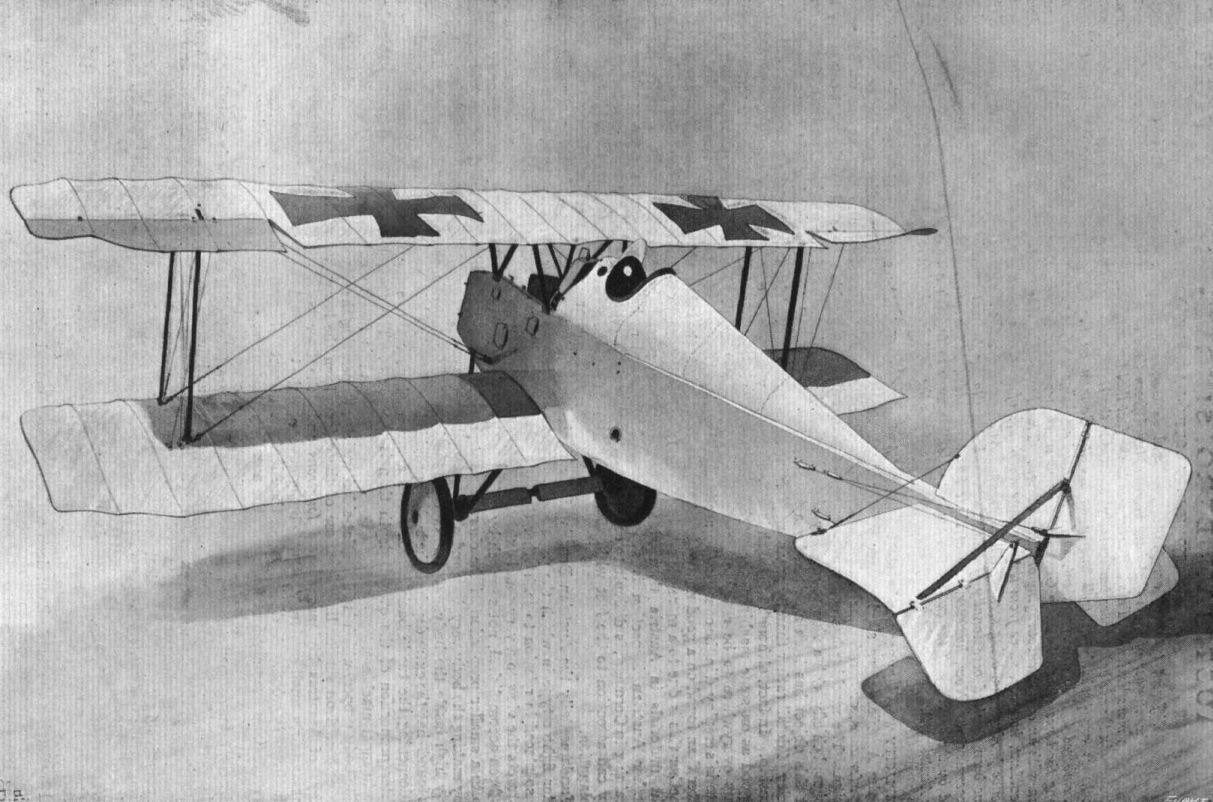
The Austrian-Berg single-seater fighter.
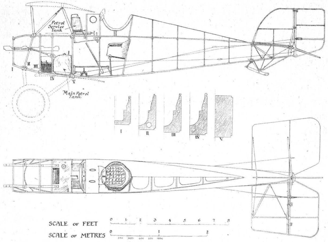
Fig. 1. - Side elevations and plan, to scale, of the body of the Berg single-seater.
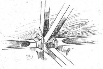
Fig. 2. - Sketch showing attachment of struts to longerons on the Berg single-seater.
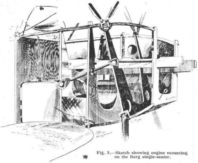
Fig. 3. - Sketch showing engine mounting on the Berg single-seater.
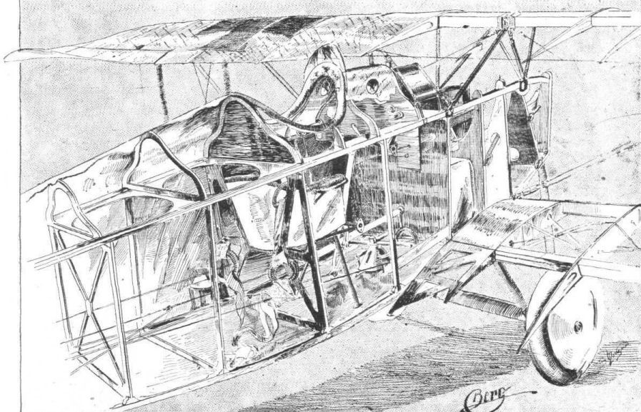
Fig. 4. - Three-quarter rear view of the front portion of the Berg. The covering has been removed to show the internal construction. In the top plane it would appear at first glance that only one spar is fitted. This is not, of course, the case, but is caused by the fact that the front spar is very close to the leading edge, and is therefore, in this particular view, covered by the rear spar.
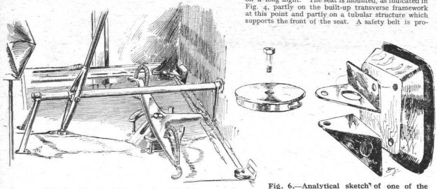
Fig. 5. - Sketch of the controls of the Berg.
Fig. 6. - Analytical sketch of one of the pulleys over which the rudder cables travel.
Fig. 6. - Analytical sketch of one of the pulleys over which the rudder cables travel.
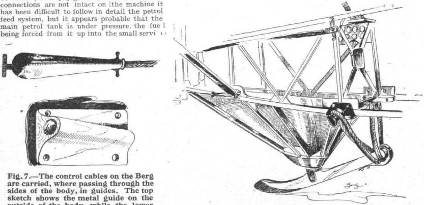
Fig. 7. - The control cables on the Berg are carried, where passing through the sides of the body, in guides. The top sketch shows the metal guide on the outside of the body, while the lower drawing illustrates the wood guide employed on the inside of the three-ply body covering.
Fig. 8. - The tail skid of the Berg is mounted, as shown in this sketch, on a structure of wood strips, covered with three-ply. The shock absorbers are in the form of coil springs.
Fig. 8. - The tail skid of the Berg is mounted, as shown in this sketch, on a structure of wood strips, covered with three-ply. The shock absorbers are in the form of coil springs.
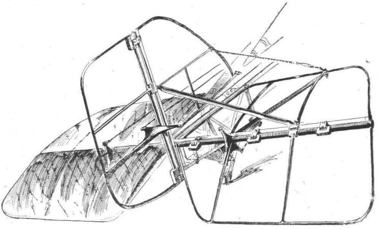
Fig. 9. - The tail planes of the Berg single-seater.
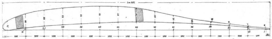
Fig. 10. - Wing section of the Berg single-seater. All the dimensions are in mm.
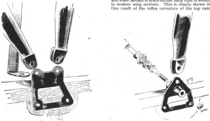
Fig. 11. - Attachment of front centre-section struts to fuselage of the Berg single-seater.
Fig. 12. - Attachment of rear centre-section struts to top longerons on the Berg single-seater.
Fig. 12. - Attachment of rear centre-section struts to top longerons on the Berg single-seater.
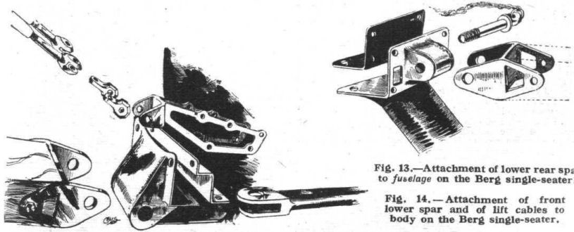
Fig. 13. - Attachment of lower rear spar to fuselage on the Berg single-seater.
Fig. 14. - Attachment of front lower spar and of lift cables to body on the Berg single-seater.
Fig. 14. - Attachment of front lower spar and of lift cables to body on the Berg single-seater.
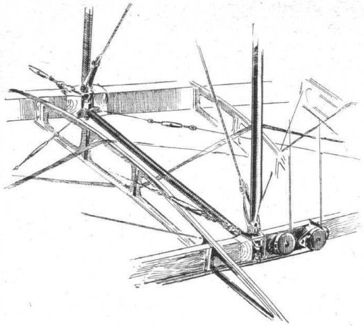
Fig. 15. - General sketch of internal bracing and of inter-plane strut attachment on lower plane of the Berg single-seater.
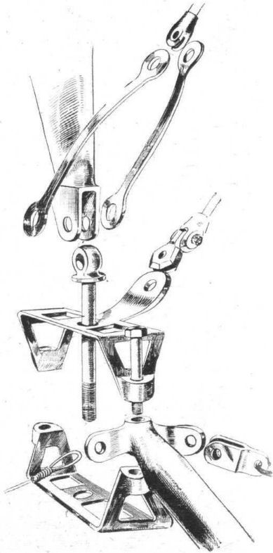
Fig. 16. - Analytical sketch of inter-plane strut attachment, lift cable attachment, internal drift bracing and compression tube in lower plane of the Berg single-seater.

Fig. 17. - View from outside of the strut fitting dissected in Fig. 16, also showing mounting of pulleys for aileron control cables.
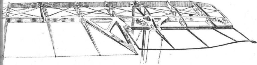
Fig. 18. - Sketch showing part of top plane and one of the ailerons of the Berg single-seater.
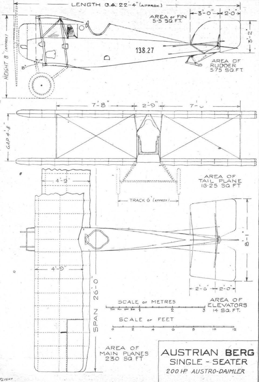
Plan, side and front elevations, to scale, of the Berg single-seater.
Flight, January 17, 1918.
FROM OTHER LANDS.
AUSTRIAN AGO AND LOHNER FLYING BOATS.
("Aerial Age," U.S.A., from material supplied by the U.S.A. Government.)
Two types of Austrian seaplanes which have fallen into the hands of the Italians during the present year, and regarded as worthy of special note, are the Ago and Lohner types. The Ago Sea-Pursuit Biplane described here and shown in the accompanying line drawing, bore the number "A-25"; it was captured May 18th, 1917. The Lohner-type flying boat (described later in this article) was brought down on the night of January 12th, 1917, and it was marked "K-301."
<...>
2.- The Lohner Flying Boat.
This is an enlarged machine of the Lohner type, retaining the V which is typical of the Lohner aeroplanes. There are six steel struts on either side and, two by two, are connected in transverse planes with steel tubes of 40 mm. outside diameter. The distance between two struts in the direction of the brace is 1.30 m., and in the direction of the spar 2.17 m.
General Dimensions.
Span, upper plane 9.70 m.
Span, lower plane 7.20 m.
Chord, upper plane 2.70 m.
Chord, lower plane 2.20 m.
Hull, maximum length 12.50m.
Bomb carrying capacity 400 kg.
Motor, Austro-Daimler 300 h.p.
In form the ailerons are trapezoidal, like that of the Italian Lohner machines. Length of ailerons, 3.47 m.; mean width, .90 m.
Dimensions of the empennage or tail group: Length of horizontal stabiliser or tail-plane, 4.74 m.; width, 1.27 m. Length of tail-flaps or elevators, 4.74 m.; width, .87 m. The vertical rudder differs from that of the old Lohner machines in that there is a small balancing area forward of the pivot.
The principal dimensions of the hull are: Maximum width, 1.50 m.; maximum length, 12.50 m.: maximum height, 1.20 m.; step .25 m.
The body has two seats side by side and one in front, upon which is mounted a machine gun arranged to be movable and fired in any direction. Besides the pilot, next to the observer, there is also a machine gun arranged on a movable tube inside the casing. The outside tube is the only additional piece the machine contains.
The turret is armoured. No bomb-dropping devices have been located. There are two vertical pieces of wood, with a circular profile notch fastened to the floats under the wings. It may be that these are used to drop large bombs, but no discovery has been made which would show how they are secured in them. Several hooks for small bombs were found.
The lateral or wing-floats, instead of being hemispherical in shape, have a bow with good streamlines, which plough on the water surface like the prow of a ship. The accompanying drawing shows their general outlines. Each is 88 cm. wide and 181 cm. long.
The engine, an Austro-Daimler, has 12 cylinders arranged in a V. It is rated at 300 h.p.
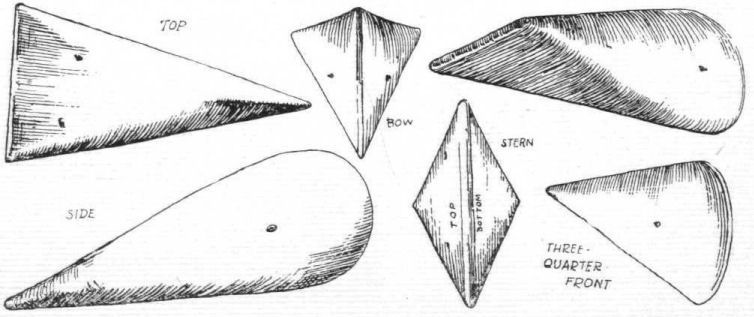
The wing-float used on the "K-301," an Austrian 3-seater flying boat of the Lohner type.
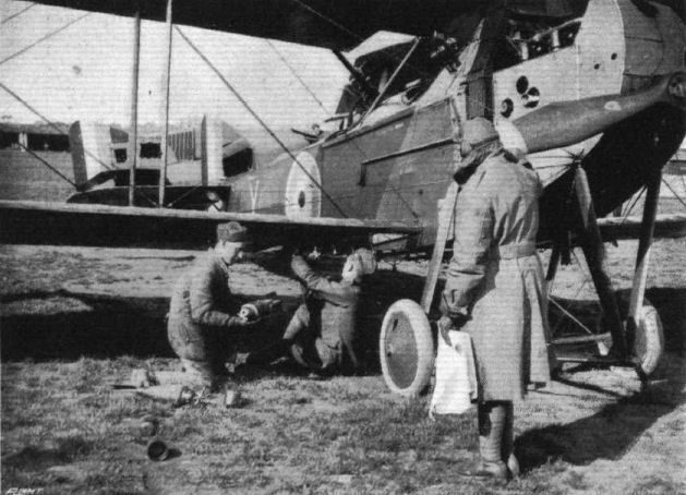
The German Offensive on the Western Front in France. - Fixing bombs to drop on massed Germans.
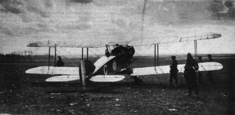
F.2B of No. 22 Sqn at Vert Galand on 1 April 1918, the birthday of the R.A.F.
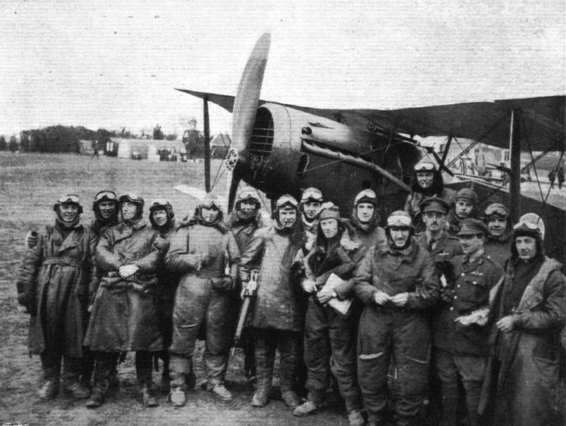
A famous R.A.F. Squadron on the British Western Front in France during the present German offensive. At least three enemy machines have been brought down by every pilot and observer in the above group.
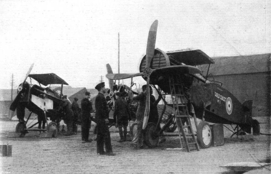
R.F.C. SALVAGE WORK. - Renovating and re-assembling aeroplanes.

The Bristol monoplane.
Flight, June 20, 1918.
THE DE HAVILLAND IV BIPLANE.
300 H.P. ROLLS-ROYCE ENGINE.
THIS large aeroplane, employed for long distance reconnaissance and for bomb dropping, is chiefly built by the Aircraft Manufacturing Co., Ltd. The different machines show minor differences in construction and outfitting according to the time of construction. Both wings of the two strutter biplane, which have distinctly rounded tips, have a span of 12.93 metres and a chord of 1.67 metres. The stagger is 0.32 metres. There is no sweep-back, but the upper and lower planes are attached respectively to a centre section 0.7 metre wide and direct to the body, at a dihedral angle of 174#. The pilot, whose seat is right under the top plane centre section, has a good view forward. The centre section and wings have their trailing portions cut away in the centre to give a better view backwards. The angle of incidence is 3# at the body and at the top plane centre section. Both main spars, which are of spruce, are of one section, left solid where occur the compression ribs. At these points and where fittings occur the spars are not only left solid but are reinforced by mahogany pieces glued and screwed on. At a point between the inner inter-plane struts and the commencement of the wing flaps the main wing spars are spliced (see Fig. 2) and bound with fabric.
The wing ribs are only very slightly cambered on the under surface. Leading and trailing edges are slightly raised. Into grooves in the two flanges, which measure 13 mm. in width and 4.5 mm. in thickness, are glued and tacked with brass tacks the three-ply webs, which are provided with large lightening holes. The ribs at the struts and in the middle of each bay have flanges as wide as 37 mm. and the web between them is solid spruce between the spars. Between every two ribs, which are spaced 310 to 400 mm. apart, there is a false rib extending from the leading edge to the front spar. The internal wing bracing, which is of thick-ended wire, is in duplicate up to the middle of the outer bay. The wing covering is of a yellowish-white colour, and is sewn to the ribs in such a way that the stitches surround the whole rib. In front of the trailing edge, which is in the form of a strip of wood, eyelets are incorporated in the under surface, which serve to equalise pressure and to drain out moisture.
The crank levers of the wing flaps, which in all the planes are hinged direct to the rear spars, are made of 1.5 mm. sheet aluminium, which is reinforced on either side by facings of wood riveted on. The same construction is employed for the elevator and rudder cranks. At their outer end, where the control cables are attached, the aluminium cranks are doubled over. The very simply arranged wing bracing consists of stream line wire, while the external drift bracing takes the form of cables.
The wing fittings are, as in so many other English machines, very simply carried out. 3 mm. thick sheet steel plates at the outer plane struts, and 3 mm. and 2 mm. at the inner struts, having lugs bent to the angle of the bracing wires, are secured to the wing spars by two bolts. A large forked bolt passes through the centre of the spar while a second smaller one passes down the outside of the spar. The interplane struts, which are made of spruce, are of stream line section, and the inner struts are kept stronger than the outer ones. On the ends of the struts are short sheet steel shoes into which are riveted aluminium packing pieces hollowed out in the centre. Through these are passed 8 mm. steel bolts, which rest in the forked end of the spar bolts, the bracing wires keeping the struts in place. The struts for the top plane centre section are similarly attached.
The fuselage is covered with ply wood up to a point behind the gunner's cockpit, this part being built up without the use of diagonal bracing. The longerons are of spruce and the engine bearers of ash. The formers as well as supports for controls and machine guns are made of ply-wood, some of which is 13-ply and as much as 26 mm. thick. The fittings for the attachment of the lift wires are each connected with two 8 mm. through-bolts. The after portion of the fuselage is carried out in the usual manner as a girder, and the longerons are spliced. This does not apply to the extreme rear part underneath the tail plane, which is covered with ply-wood 3 mm. thick. In the front the fuselage has a rounded top. From the observer's seat vertical formers gradually carry the top into the rectangular section at the beginning of the tail plane.
The undercarriage (Figs. 9, 10 and 11) is very light in proportion to the heavy machine. It weighs 54 kg. Each pair of struts is of solid wood and is not bound with fabric. Screwed to the struts are vertical strut-shoes of wood, which carry, in addition to the wheel axle, horizontal tubes for the attachment of the rubber shock absorbers. The axle rests between two cross-struts of wood, which are shaped to a fair shape and connected at the bottom by 3 mm. three-ply. (See upper left-hand corner of Fig. 10.) In order to cause no eddies during flight the axle is fitted into the stream line casing thus formed by covering its upper side with a layer of wood suitably hollowed out and secured to it with a wrapping of fabric. In order to better guide the axle in the slots in the struts this casing of wood is left square at this point, and entirely surrounds the axle. It is covered with sheet metal. The diagonal bracing of the undercarriage is in the form of stream line wire, and is only placed in the bay of the front chassis struts. In addition there is a horizontal tension wire running in front of the stream line cross-strut.
The tail-plane, which is of rectangular plan form with rounded corners, is so attached to the body that its angle of incidence can be varied from the pilot's seat, during flight, from + 2· to + 5·, as in the Sopwith. For this purpose its front spar is so mounted as to be free to rotate, while the rear spar with its bracing is secured to a vertical tube placed in front of the stern post (see Fig. 13). This tube carries a thread engaging with an internally threaded bobbin, bolted to the stern post but free to rotate, operated by a hand wheel and cables, and forcing by its rotation the thread, and with it the vertical tube, up or down. The two elevator flaps, hinged to the tail plane, are not connected to one another. The rudder has a balanced portion as do many German machines.
The 12 cylinder Rolls-Royce motor develops, according to the firm's plate on it, 300 h.p. at 1,650 r.p.m., when the hourly consumption is 105 litres of petrol and 4.5 litres of oil. The speed is not to exceed 1,800 r.p.m. In general arrangement the engine is similar to older types of the same make, but it has four carburettors. The exhaust is either carried over the top plane or direct through short collectors slanting outwards from the body. The nose of the fuselage is formed by a radiator fitted with shutters over its upper part. Through an opening in the centre of the radiator projects the reduction gear of the engine, which reduces the speed of the airscrew to 900 r.p.m.
Under the front of the body is placed transversely the oil tank, which has a capacity of 21 litres. The main petrol tank, which is arranged for air pressure, has a capacity of 256 litres and is placed behind the pilot's seat. A gravity tank holding 28 litres is placed under the left top plane. Sufficient fuel is carried for a flight of about 2 3/4 hours' duration. In another machine there is an additional tank holding 76 litres, which brings the capacity up to about 3 3/4 hours.
More recent machines have, instead of the one pressure tank, and mounted in the same place, two tanks placed side by side, each of which is provided with a supply pump driven by a small propeller. With this arrangement a spring-loaded valve is provided inside the tank, which returns any surplus of petrol to the tank. The two leads from the main tanks and that of the gravity tank are joined at the engine to an omnibus tube, to which is attached a manometer for controlling the tanks.
The machine is provided with complete dual control. The control lever of the observer is removable (see Fig. 16). The wing flaps are inter-connected. Their cables run on the outside of the wings along the leading edge. Each wing flap has two crank levers. The upper and lower flaps are connected by two stream line wires. In the same manner the elevator and rudder cables run on the outside of the fuselage. The rudder cables are in duplicate, while each of the elevator flaps has single control cables.
The equipment of the pilot's and observer's cockpits differs in individual machines. On an instrument board in the former, provided with illumination for night flying, are the following instruments: Speed indicator, revolution counter, altimeter, thermometer, clock, hand pressure pump, inclinometer, map board and compass. To the left of the pilot the various petrol pipes are so arranged that the different cocks are within easy reach. On the same side are arranged oil and petrol pressure indicators, a pressure pump fed from the gravity tank, and also on a common axis the throttle, spark advance lever, and mixture regulator for altitude work.
On the throttle rods a catch lever is so arranged that when the throttle is closed the lever for regulating the mixture at altitudes will return with it. To the right of the pilot are arranged the cables controlling the radiator shutters, the switch for night illumination, and shelf for signal cartridges. Petrol level indicators are not fitted.
In the observer's cockpit are placed: Speed indicator, altimeter, throttle and switch for night illumination. Observer's and pilot's cockpits are placed far apart on account of the main petrol tanks being placed between them. For communication between the occupants there is a speaking tube on the right, and on the left an endless cable passing over rollers in the two cockpits. Behind the observer's seat is the mounting for the camera with adjoining shelves for the slides. The presence of a wireless outfit could not be ascertained in any of the machines. The armament consists of two interconnected machine guns mounted on a turntable in the observer's cockpit, and of a fixed machine gun for the pilot mounted on the left of the top covering of the body. The control of the fixed machine gun is accomplished hydraulically by a control mechanism placed immediately behind the airscrew. This mechanism is driven off a pinion on the hub of the airscrew, and releases two shots for each revolution of the airscrew. Firing of the gun is accomplished from the control lever. A spring-controlled hand pump for filling the leads is mounted on the floor of the pilot's cockpit. For loading there is either a lever on the gun or a cable running over a roller, provided with a grip. A telescopic sight is placed to the right under the gun, in front of the rectangular wind screen. As the observer's seat is placed rather far aft a good field of fire is also obtained from here in an outward and forward direction.
The bomb gear, judging from the makeshift way in which the release gear is built, appears to have been added as an after-thought. Bomb racks, either arranged for four smaller or for one large bomb are placed under the lower wings and under the body. The release is accomplished from the pilot's seat by means of Bowden cable. The cables are either joined at the right of the seat or arranged separately on the outsides of the body. A sighting arrangement is built into the body immediately behind the rudder bar. It consists of a square plano-concave glass plate, 15 mm. thick at the edges and 5 mm. thick in the centre (see Fig. 12). Underneath this are three wire rods soldered at right angles to a fourth rod lying in the direction of flight. 17 cm. further down is another longitudinal rod, and a transverse rod working in longitudinal slots, and which can be locked in place by screws.
The weight of the machine empty, but including cooling water, was ascertained to be 1,110 kg. If the maximum useful load is assumed to be 590 kg. we obtain a total weight of 1,700 kg. As the area is 40.3. sq. m., the loading is 1,700:40.3 =42 kg./sq. m. The load per h.p. 1,700:300 = 5.7kg./h.p.
Weights.
Kilogs.
Motor 390.0
Exhaust pipes 15.0
Radiator and water 76.9
Airscrew 42.0
Petrol tanks 28.0
Oil tank 4.5
Engine accessories,
leads, &c 19.6
Body with cowl 175
Tail plane-
Incidence gear 2.5
Body accessories -
Seats, &c. 8.0
Undercarriage 54.0
Tail skid 5.0
Controls 9.5
Wings 209.0
Bracing 31.0
Armament supports 40.0
Total 1110.0
Loads
Kilogs.
Crew 150.0
Armament 73.6
12 bombs, about 144.0
Photographic outfit 10.0
Wireless arrangement 5.0
Fuel 205.0
Estimated useful load 590 Kilogs.
Weight of wings 5.2 kg. sq.m.

Bringing back the photographic evidence of bombs dropped during a day raid on the British western front in France.
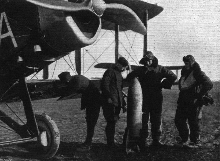
A daylight bombing squadron preparing for business on the western front in France. Note the Liliputian "egg."

A bombing machine on the British western front in France tucking its eggs under its wings prior to a daylight trip, with one of its attendant fighting scouts in waiting.

THE GERMAN OFFENSIVE ON THE WESTERN FRONT IN FRANCE. - A day-bombing squadron. Some of the big bombing machines.

Fig. 7. - Side view of the de Havilland IV biplane.
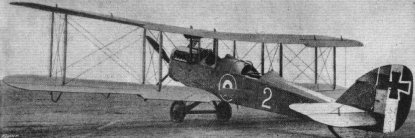
Fig. 15. - Three-quarter rear view of the de Havilland IV biplane.

Fig. 14. - Three-quarter front view of the de Havilland IV biplane.
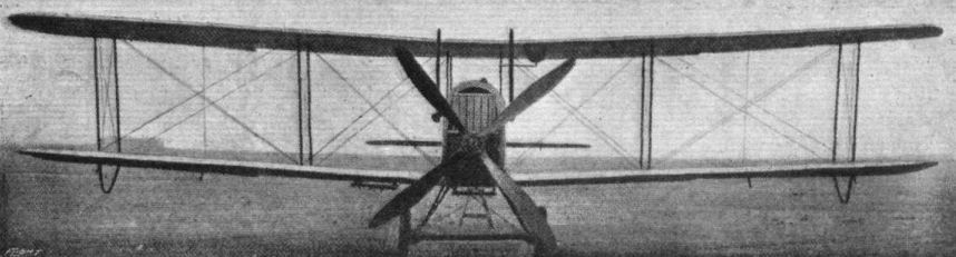
Fig. 5. - Front view of the de Havilland IV biplane.
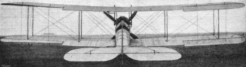
Fig. 6. - Rear view of the de Havilland IV biplane.
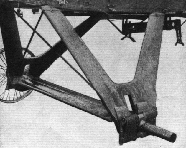
Fig. 11. - Undercarriage of the de Havilland IV biplane.
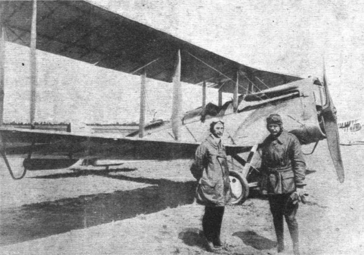
Orville Wright (left) in front of a Liberty D.H. 4.
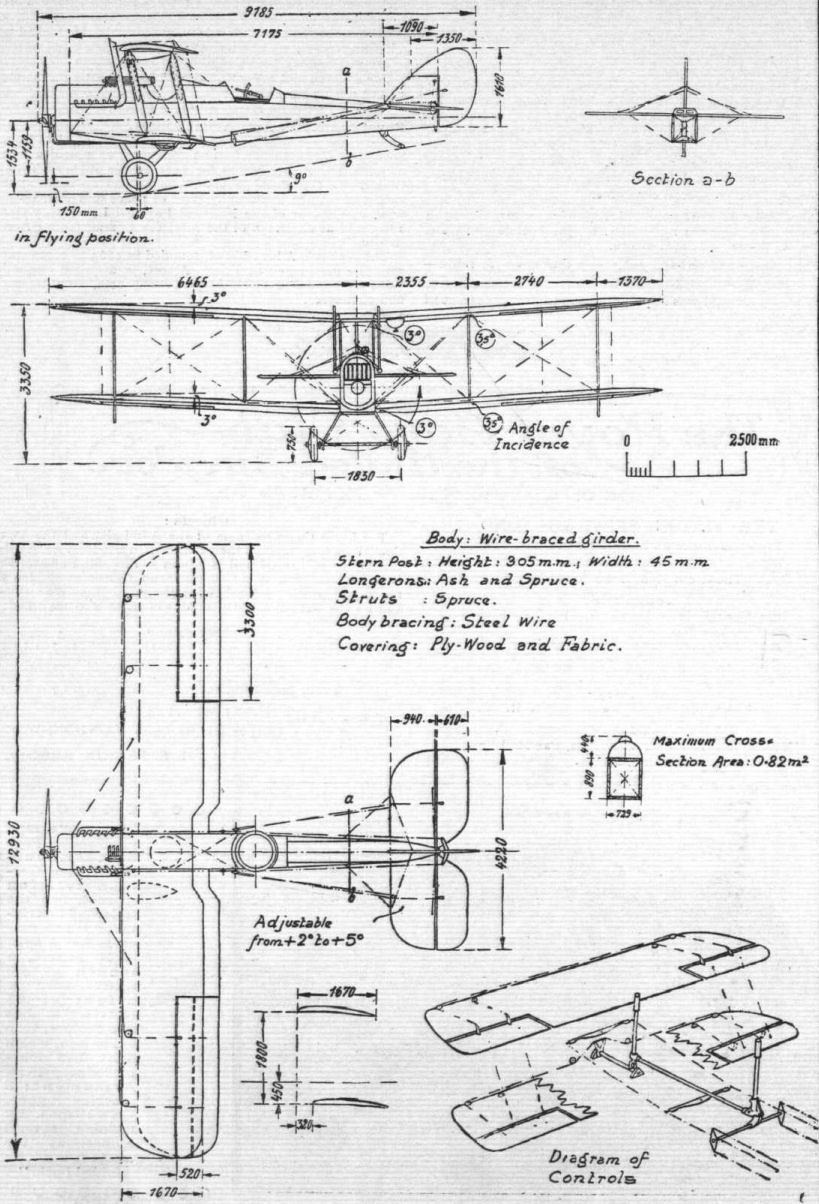
Fig. 1. - Scale drawing of the de Havilland IV biplane.
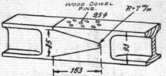
Fig. 2. - Wing spar splice.
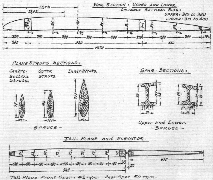
Fig. 3. - Wing section and tail plane section of the de Havilland IV biplane.

Fig. 4. - Scale drawing of the body of the de Havilland IV biplane.

Fig. 8. - Inter-plane strut attachment.
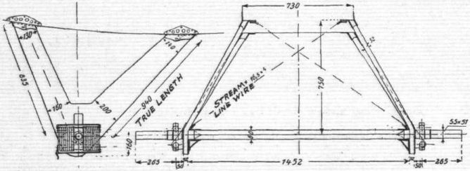
Fig. 9. - The undercarriage.
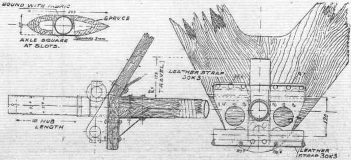
Fig. 10 - Arrangement of axle.
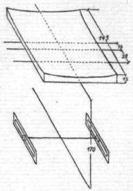
Fig. 12. - Bomb sight of the de Havilland IV biplane.
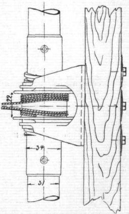
Fig. 13. - Tail plane incidence gear.
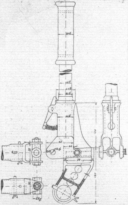
Fig. 16. - Control lever in the observer's cockpit of the de Havilland IV biplane.
Flight, October 24, 1918.
THE D.H.5 PURSUIT BIPLANE
THE D.H.5 pursuit biplane herewith described was built by the Darracq Motor Engineering Co., Ltd., London, and bears the identification mark A 9435. It is a tractor biplane, with a single pair of interplane struts on either side and with the wings set at a negative stagger of 0.695 m.
Both wings have a span of 7.84 m. and a chord of 1.375 m . The upper wings are fixed to a centre section, while the lower are joined to wing roots at the height of the lower bottom longitudinals. There is no sweepback, but both wings have a dihedral of 172°; the angle of incidence of the upper wing is 2° amidwings and 2 1/2° at the tips, while that of the lower wing is 2 1/2° throughout.
The wing spars are of spruce and of I-section. The ribs are spaced from 280 to 350 mm., and between each two ribs there are two false ribs, reaching from the leading edge to the front spar. The interplane and cabane struts are made solid of spruce, and the flying and landing stays are of streamlined wire.
Ailerons are carried on both wings, hinged to the rear spar.
Side Elevation.
The control leads, of streamlined wire, run outside the planes, below in front of the leading edge, and above, over the front spar.
The body is of the ordinary four-longitudinal type braced by cross wiring, and is strengthened, in front, up to the pilot seat, and at the rear, underneath the tail plane, by a planking of 3 mm. plywood. Suitable formers give the body in front a neat circular cross section, the whole body being covered with canvas.
The undercarriage is of the V-type, with solid, streamlined wooden struts, and a continuous axle which rests between two auxiliary axles. The spring range of the axle is not limited in any way.
The tail plane is of one piece, and is mounted on the body at an angle of incidence of 1 °, without the customary incidence-change gear. The elevator is of the divided type, each portion having its own crank with single control leads.
The power plant consists of a 110 h.p. rotary Le Rhone engine, which is known to have developed 130 h.p. in earlier tests. The main fuel tank contains 100 litres of gasoline, and the oil tank has a capacity of 21 litres; both are mounted behind the pilot. There is in addition an emergency gravity fuel tank of 26 litres capacity, which is mounted on the upper starboard wing. The engine is fed from the main tank by compressed air, generated by a small air pump, which is attached to the left forward undercarriage strut. The total fuel supply insures a flight endurance of about two hours.
The following instruments are mounted in the pilot cockpit: To the right, two fuel supply pipes with stop cocks, and a change gear for the elevator control; on the instrument board, tachometer, speedometer, altimeter, spark switch, watch, and compass; to the left, fuel and oil throttles, and a hand pump for the air. Two machines of the same model, which were built by the Aircraft Manufacturing Company, Ltd., London, have the instruments disposed in a much handier manner, and re also fitted with an electric lighting system for night-flying.
The armament of the D.H.5 consists of a Maxim machine gun, which is synchronised to fire through the airscrew and is mounted on the nose of the machine to the left of the pilot. The control is of the hydraulic type, and the release is effected by means of a Bowden cable. The cartridges are carried in a metallic belt, and the box into which it ruffs is fitted directly below the machine gun, behind the engine.
The weight of the machine, empty, is 461 kg., and, fully loaded, is 694 kg. The wing area being 20.14 sq. m., and the horse-power being assumed 130, the wing loading appears to be 34.4 kg. per sq. m., and the power loading 5.33 kg. per horse-power.
The great visual range of this machine is noteworthy, both forwards and upwards: this feature has been achieved by the negative stagger of the wings, as well as by placing the tanks behind the pilot seat. While this arrangement does not possess any aerodynamic drawbacks for longitudinal stability, it would seem as if the increase of the angle of incidence of the upper wing toward the tips should unfavourably influence transverse stability.
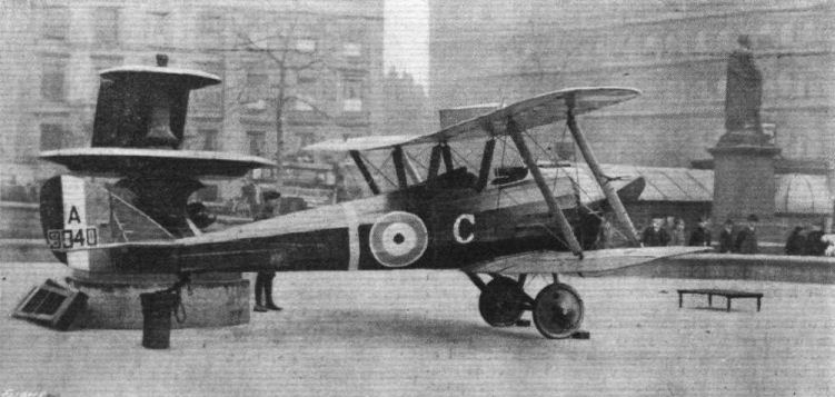
Side view from behind of the D.H. 5 biplane on view in Trafalgar Square in connection with the Y.W.C.A. Blue Triangle Week.

A D.H. 5 biplane on view in Trafalgar Square in connection with the Y.W.C.A. Blue Triangle Week. Front view.
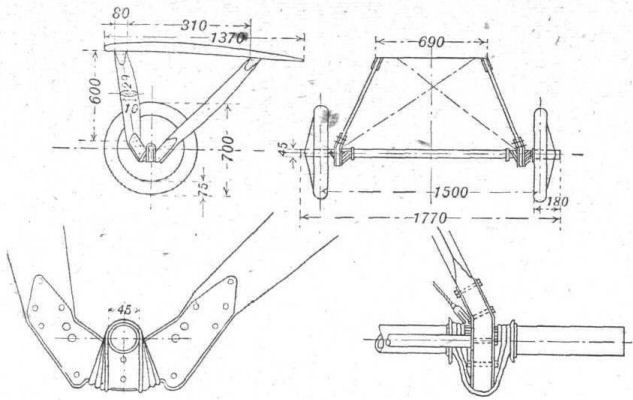
Details of the undercarriage of the D.H.5.
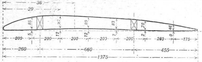
Wing section of the D.H.5.
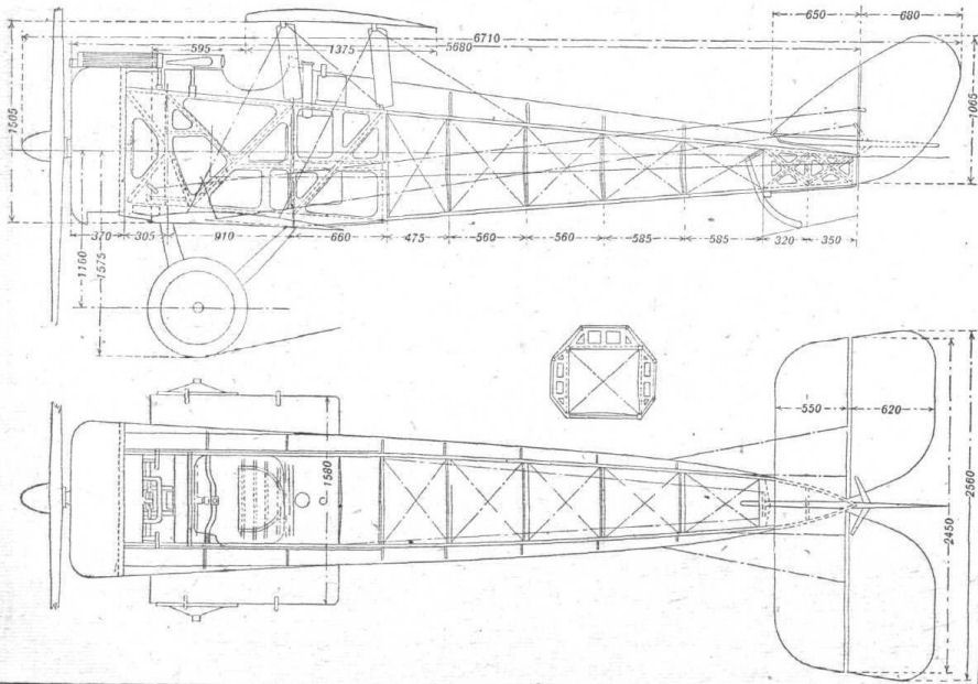
Detailed view of the body of the D.H.5 in side elevation and plan
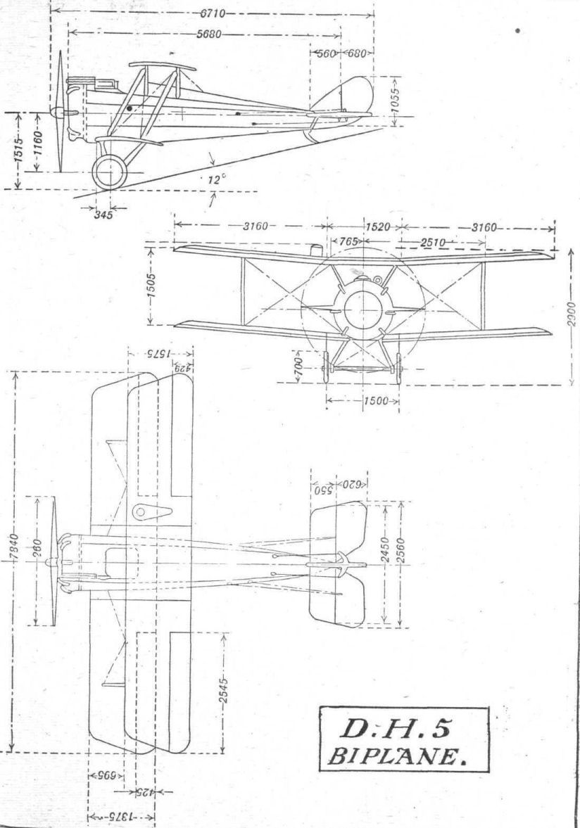
General arrangement of the D.H.5 biplane.
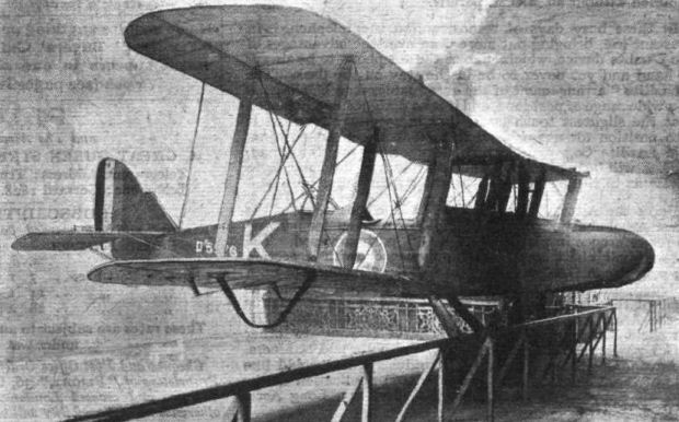
A de H. 9 biplane at the Enemy Aircraft Exhibition, Agricultural Hall. - These machines have done some excellent work at the front, and a similar machine is now going to be turned to more peaceful pursuits, for we learn that Sir Arthur Du Cros has ordered one from the Aircraft Manufacturing Co., Ltd., for his private use.
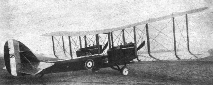
A FAST TWIN-ENGINED BOMBER. - One of the Aircraft Manufacturing Co.'s machines designed by Capt. G. de Havilland. This is a de H. 10a, and is fitted with two Liberty engines, each of 400 h.p. The machine has an extraordinarily good performance, its speed at ground level being 134 m.p.h. and at 10,000 ft. 124 m.p.h. The climb to 10,000 ft. takes only 10.3 minutes, while it is capable of reaching an altitude of 22,500 ft. The military load is 1,000 lbs. and the machine has a range of 700 miles. Note its similarity to D.H. 3, except that it is a tractor instead of a pusher.
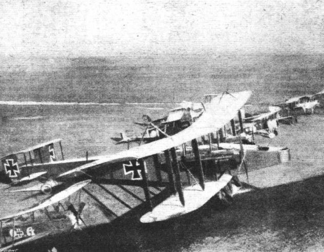
"Prisoners of War." - A batch of Allied aeroplanes captured by the Germans. In the foreground is a Handley-Page bomber.
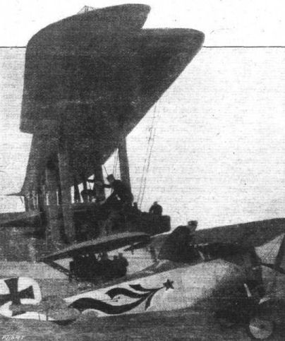
THE LONG AND THE SHORT OF IT. - A Handley-Page bomber and a Nieuport single-seater are objects for Hun curiosity.
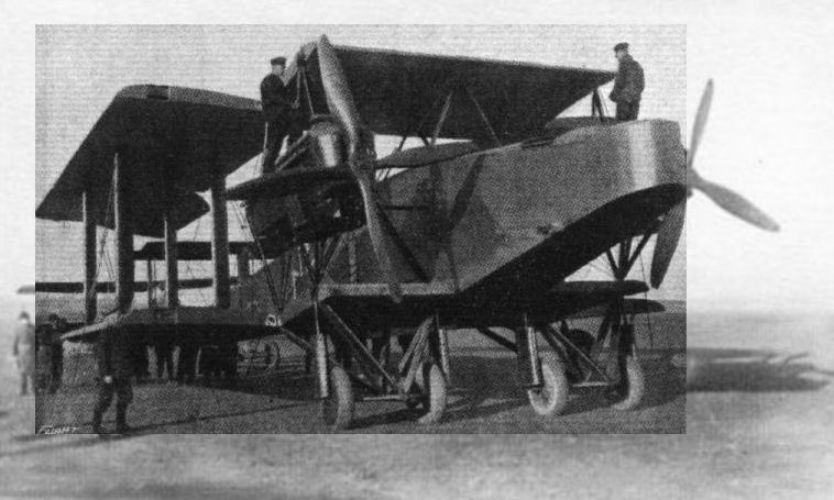
При перелете первой группы бомбардировщиков с Британских островов на фронт, один из HP O/100 по ошибке сел на вражеской территории. На снимке: германские специалисты изучают трофейный самолет
This photograph of a Handley-Page bomber, published In a German aviation journal, has the following inscription: "The machine has a span of 30 metres, a length of 20 metres, and a height of 6 1/2 metres. It has two motors, each of 260 h.p., which drive two four-bladed propellers. Armament: 3 machine guns. Crew: 5 men. By undoing several connections the wings can be folded back."
This photograph of a Handley-Page bomber, published In a German aviation journal, has the following inscription: "The machine has a span of 30 metres, a length of 20 metres, and a height of 6 1/2 metres. It has two motors, each of 260 h.p., which drive two four-bladed propellers. Armament: 3 machine guns. Crew: 5 men. By undoing several connections the wings can be folded back."
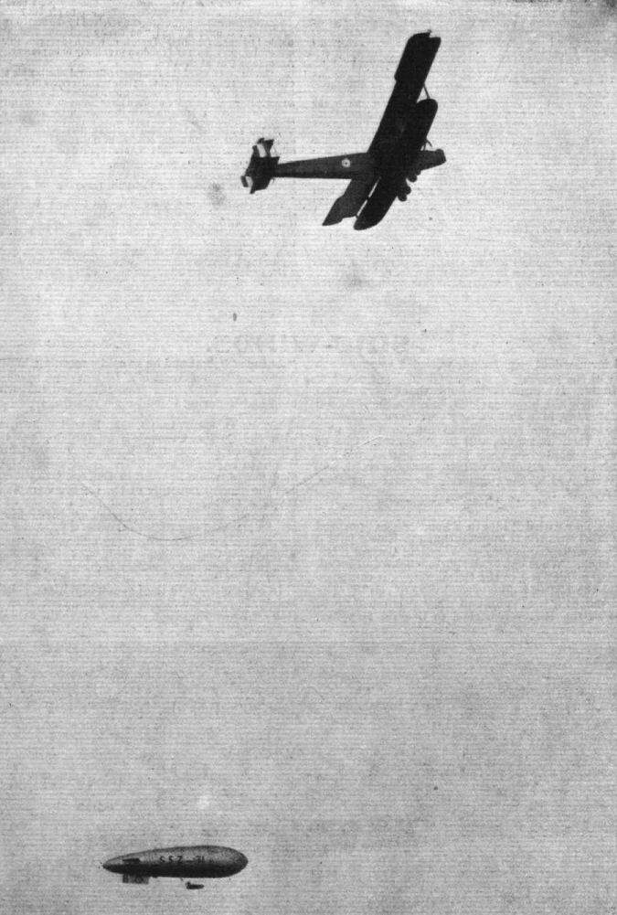
The Handley Page bombing machine, fitted with Sunbeam-Coatalen aircraft engines, photographed whilst flying over London. Note the Army airship in the bottom of the picture.

Even journalists are now allowed officially to fly the Channel upon occasion, just for the experience of the thing on their way to the fighting front. Here is such a "freight" for an "H.P." in flying kit, ready for their journey.
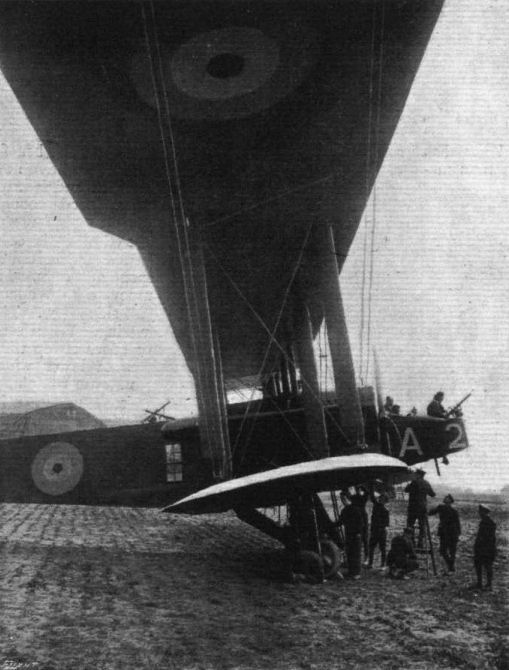
ON THE WESTERN FRONT IN FRANCE. - A "Baby" R.A.F. machine being tuned up before starting off for Germany with a load of bombs.
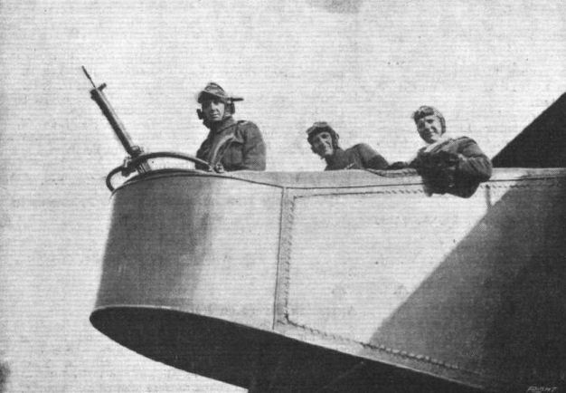
On the British Western Front in France - A trio of R.A.F. fighting men in the nose of a Handley-Page.
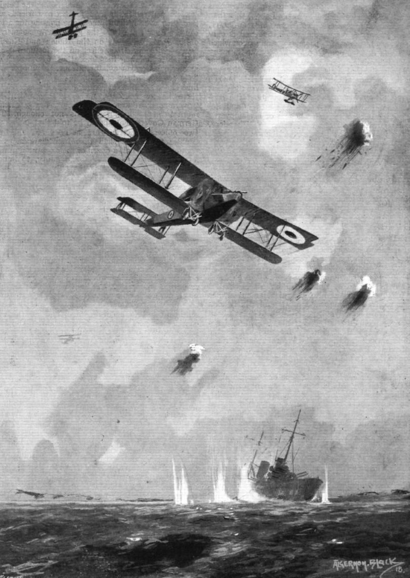
Bombing the stranded "Goeben" in the Dardanelles.
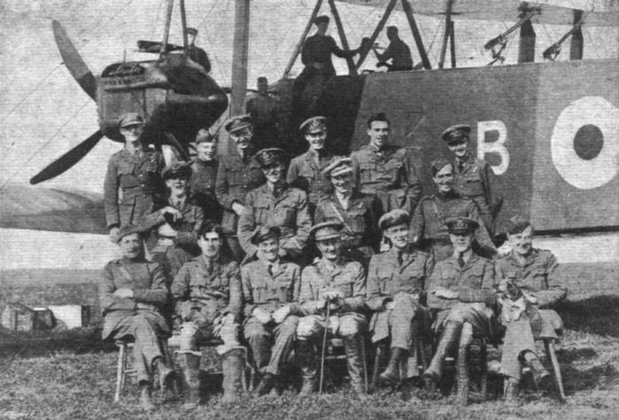
A group of "Tails up" pilots belonging to a bombing squadron on the British Western front in France.
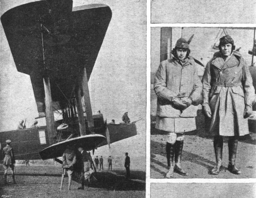
H.R.H. Capt. Prince Albert crosses to France in an "H.P." with Major Greig as pilot. Prince Albert and Major Greig are seen in flying kit, and, in the 'plane (at the rear), ready to start.
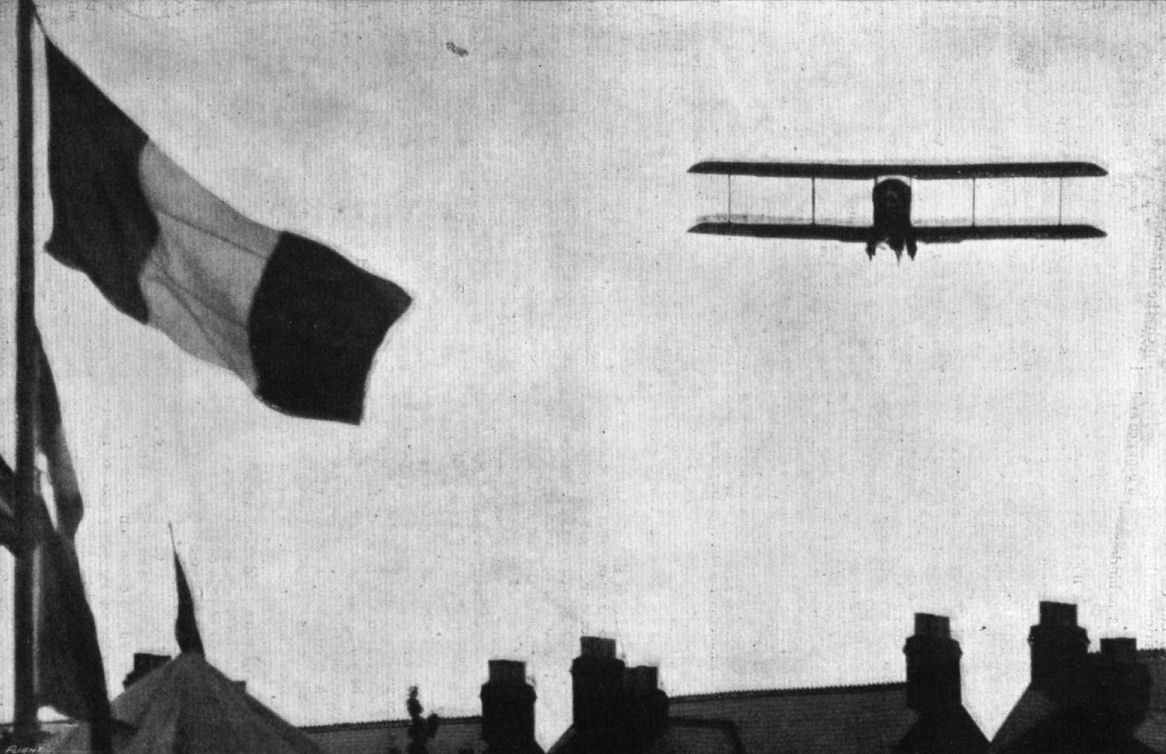
DIPPING AT THE "SALUTING POINT" ON THE EDGE OF THE AERODROME. - Mr. H. Sykes on his Martinsyde at Hanworth.
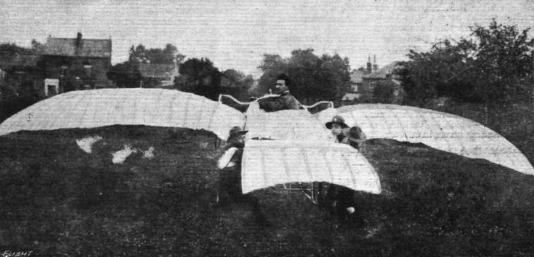
M. Passat with one of early experimental machines.
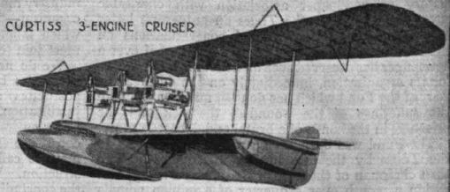
American aeroplane types of 1917-18: Curtiss 3-engine Cruiser.
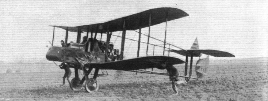
ON THE BRITISH WESTERN FRONT IN FRANCE. - With our night bombing planes in France. One of our night bombing machines returning after a flight.

A Sunday morning service in an aerodrome on the British Western front in France. - The Chaplain conducting Service from the nose of an aeroplane.
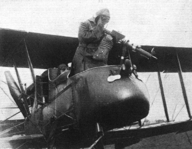
With Our Night-Bombing Planes on the Western Front in France. - The observer has very often occasion to use the gun fitted to his seat, and his method is seen when firing down on the enemy.
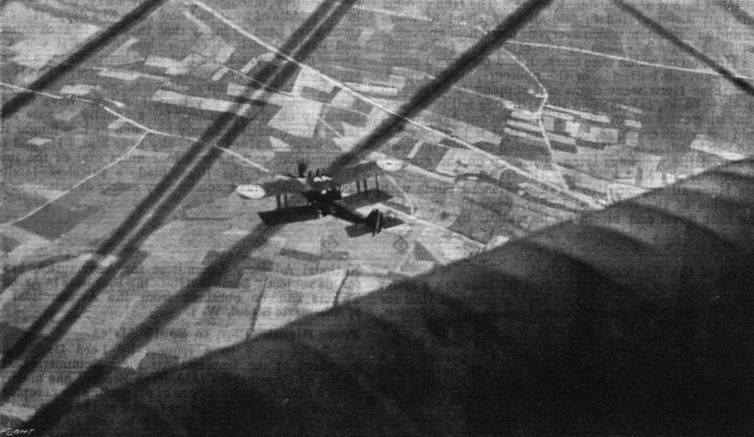
ON THE BRITISH WESTERN FRONT IN FRANCE. - An observation flight over the German lines by our aeroplanes.
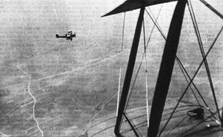
ON THE BRITISH WESTERN FRONT IN FRANCE. - Our aeroplanes, on observation bent, over the German lines.
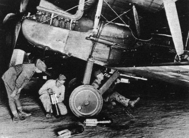
On the British Western Front. - Preliminaries to a bombing expedition.
Attaching bombs to the racks beneath an RE8 of 69 Squadron at Savy, October 1917. The unit subsequently became 3 Squadron AFC at Bailleul.
Attaching bombs to the racks beneath an RE8 of 69 Squadron at Savy, October 1917. The unit subsequently became 3 Squadron AFC at Bailleul.
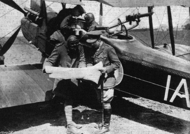
On the British Western Front in France - C.O., with pilot and observer, referring to the photos, and maps prior to setting out for the German lines.
Flight, May 9, 1918.
THE ENGLISH S.E.V.A. SINGLE-SEATER FIGHTER.
SCOUTING EXPERIMENTAL.
The following description and illustrations published in the German aviation journal, "Deutsche Luftfahrer Zeitschrift," appears to be an official German report - as it is arranged in a similar manner to other descriptions of captured British and Allied machines - on the S.E., and should, we think, he of interest.
THIS machine, which is built by Vickers Ltd., carries the number B 507, and in addition to the usual identification marks, a circle and the letter A in white. On the airscrew there is stamped S.E.V.A., from which it is to be assumed that the older machine of similar type, having a 150 h.p. Hispano engine without reduction gear, was designated as S.E.V.
Both wings of the single strutter biplane, having an area of 22.8 sq. metres, have a span of 8.15 metres, and a chord of 1.52 metres. The stagger is 0.46 m. The wings are not swept back. The dihedral angle of the wings, which are joined to centre sections, is 171·. In order to improve the view the lower wings are cut away near the body. The angle of incidence of the top wing is 5·, while that of the bottom wing is 6· at the body and 5· at the struts. Both wing spars are of spruce, and are of I section, while the spars of the short roots, which run through the body, are of steel tubing, 45 mm. outside diameter and 1.75 mm. thick. The wing ribs are of the usual type employed on English machines. Webs 1 cm. deep are glued and tacked into the grooves in the flanges, and the two webs are kept apart by vertical laths. There are no special compression struts between the main wing spars, the function of these being performed by leaving some of the ribs with a full strong web. The internal wing bracing is in the form of single stream line wires between the body and the struts. That of the overhanging portions is thick ended wire. The trailing edge of the wings is formed by a wood strip. Between every two ribs are two short false ribs running from the leading edge to the front spar. The wing fabric is stitched to the ribs and is painted a yellowish white underneath and reddish brown on top, as is also the body fabric. On the under side near the trailing edge there are eyelets for equalising the pressure.
The centre section struts are steel tubes stream lined with wood fairings. The inter plane struts are of spruce, and are fitted at their ends with sheet steel shoes to which the incidence wires are anchored. The wing bracing is in the form of stream line wires. The lift wires are in duplicate, the landing wires single. Both spars of the upper plane are braced, in addition, by wires between the centre section struts and the outer struts. Non-balanced ailerons are hinged to the rear spars of both upper and lower wings.
The fuselage, an ordinary type of girder, has a turtle-back formed by vertical formers. Up to the pilot's seat it is covered with 4 mm. three-ply wood. Longerons and struts are of I-section with the exception of the vertical struts behind the pilot's' seat, which are turned to a circular section.
The tail plane, which is cambered on both sides, is so attached to the body that its angle of incidence can be varied during flight from +4.5· to -3·. To this end its front spar is free to oscillate, while the rear spar and its bracing is attached to a tube which can be raised or lowered in the stern post of the body. This tube is secured, with a threaded portion, to a crown wheel mounted on, but free to turn, in the stern post. When the crown wheel is rotated, by means of a hand wheel and cable from the pilot's seat, it raises or lowers the tube, which carries with it the rear spar of the tail plane, thus altering the angle of incidence. The elevator, hinged to the tail plane, takes part in this movement. The elevator cables are led through tail plane and body, whereby air resistance is reduced, but which necessitates, however, two right-angle bends in each cable. Cellon windows in wings and tail permit of inspecting the pulleys.
The undercarriage is of the usual type. The wheel axle, which runs right through, is housed between two auxiliary axles. The travel of the axle is not limited.
The construction of the tail skid is unusual. This member is swivelled from the stern post and connected to the rudder control cables. A brass shoe is sprung by means of two spiral springs, prevented from buckling by having inside them telescopic tubes.
The enclosed Wolseley-Hispano engine was, according to the makers' plate, given its brake test on August 30th, 1917, and develops 206 h.p. at 2005 r.p.m. The air screw is geared down in the ratio 4:3.
The exhaust gases are carried away on each side by exhaust pipes running to a point behind the pilot's seat. The engine is so mounted that it is easily accessible when the engine housing has been removed. The radiator forms the nose of the body. Shutters operated from the pilot's seat permit of covering up about half of the radiator. The main petrol tank is mounted behind the engine on the upper longerons. It has a capacity of 120 litres. A gravity petrol tank, holding 17 litres, is mounted between the leading edge and front spar of the centre section of the top plane. An oil tank of 14 litres capacity is built into the body behind the engine. The fuel is sufficient for a flight of two hours' duration at ground level.
In the pilot's cockpit. are the following instruments, &c. :- On the right: A box for signal pistols, a switch for the starter, a change-over switch for the two magnetos, and a lever for adjusting the spiral springs regulating the elevator.
In the centre: Altimeter, hand pump, oil pressure gauge, compass, inclinometer, three-way cock for gravity and pressure petrol feeds, three-way cock for hand and motor air pumps, cooling water thermometer, petrol gauge on back of main petrol tank, manometer for air pressure. On the left: Gas lever, lever for regulating the mixture, cable for regulating the radiator shutters, rack for three signal cartridges. On the floor is mounted a hand pump for the hydraulic sighting of the machine gun, two boxes for drums for the movable machine gun, and the starter.
Weight Distribution.
Kg.
Motor 285.0
Exhaust collector 12.0
Starting gear 3.6
Radiator system 23.8
Cooling water 31.0
Airscrew 26.6
Main petrol tank 17.8
Gravity tank 6.5
Oil tank 3.9
Engine accessories 6.4
Body with seat and
engine housing 151.0
Tail plane incidence
gear 1.9
Under-carriage 40.8
Tail skid 3.7
Controls 5.4
Wings, including
bracing 112.2
Vertical and horizontal
cables 21.0
Body equipment 14.0
Total 706.0
In front of the pilot's seat is a wind screen of triplex glass. Behind the pilot's seat is a box, accessible from outside, running right through the body from side to side.
The fixed machine gun is mounted to the left of the pilot, inside the body covering. The cartridge belt is of metal. The firing of the gun is operated hydraulically by a control mechanism in front of the engine, driven by spur gearing on the propeller. The trigger is mounted on the control lever. Mounted on a bent rail above the centre section of the upper plane is a Lewis machine gun, which can be pointed to fire upwards during flight. The weight of the machine empty was ascertained to be 706 kg.
The weight of the fuel, with full tanks, amounts to 111 kg., so that the total useful load may be put down as 250 kg., thus giving a total weight of 956 kg.
The wing loading is therefore 956 : 22.8 = 42 kg. sq. metre, and the engine loading 956 : 200 = 4.78 kg. h.p.

PRESENTATION OF AEROPLANES AT BROOKLANDS ON JULY 6TH. - One of the machines presented by the Hon. H. Burton, K.C., a representative of the Union of South Africa, to the R.A.F., and accepted by Major J. L. Balrd, Parliamentary Secretary of the R.A.F.
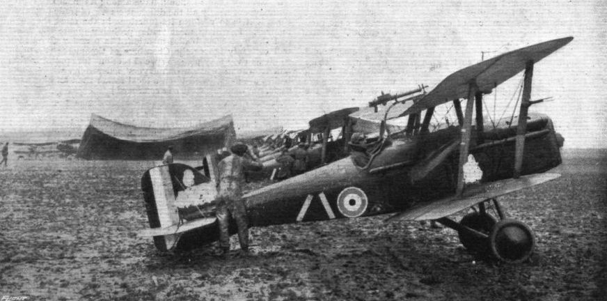
THE GERMAN OFFENSIVE ON THE WESTERN FRONT IN FRANCE. - R.A.F. scouts ready to start away on a "stunt."
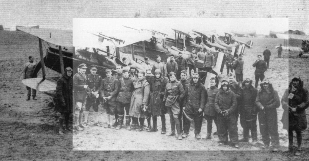
THE GERMAN OFFENSIVE ON THE WESTERN FRONT IN FRANCE. - R.A.F. scouting squadron, who fly low to use their machine guns on the enemy masses.
32 Squadron arrived in France in May 1916 and spent the rest of the war as a fighter unit, acquiring a distinguished reputation. Here, in early 1918, the crews stand with their SE5a aircraft.
32 Squadron arrived in France in May 1916 and spent the rest of the war as a fighter unit, acquiring a distinguished reputation. Here, in early 1918, the crews stand with their SE5a aircraft.
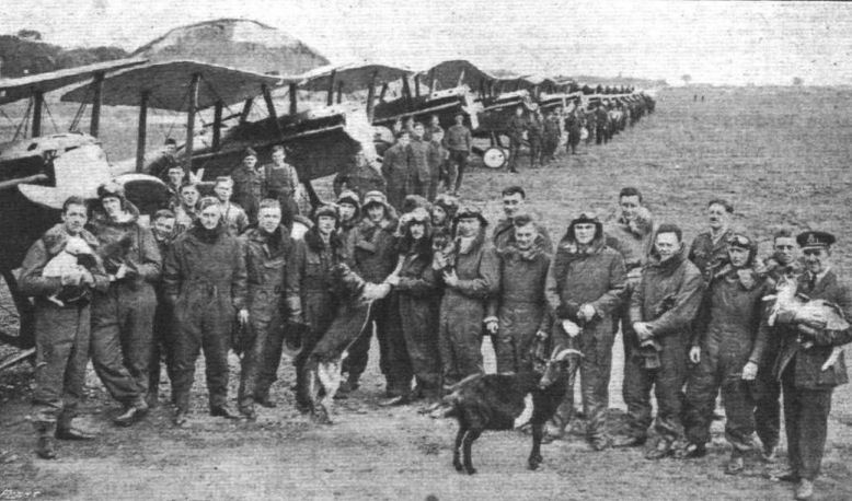
Pilots of a renowned R.A.F. Scouting Squadron which has done good work on the British Western Front in France.

A squadron of scouts on the British Western front in France, where they have been doing first-class work.
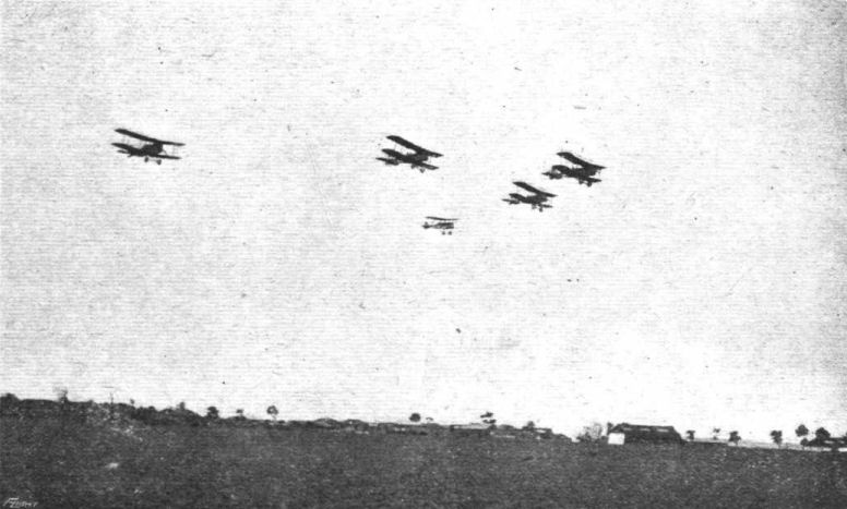
R.A.F. fighting planes leaving their aerodrome in France, in formation, for the enemy lines.
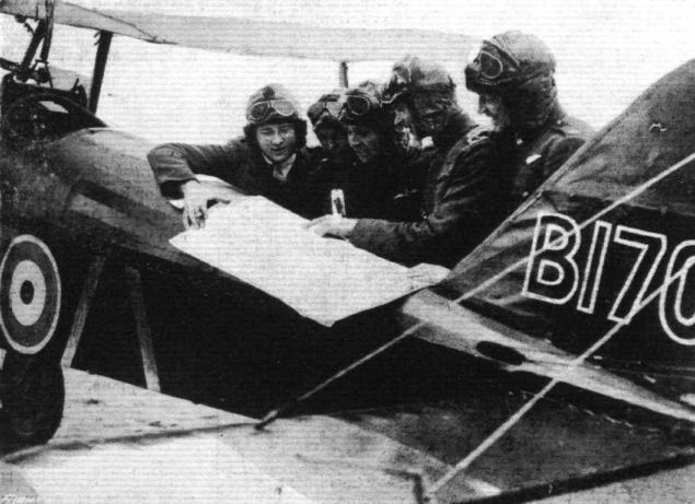
A Cosmopolitan Group of Pilots in an RAF. Squadron on the British Western Front in France. - An American, Canadian, New Zealander, Englishman, and South African.

Rear view of the S.E.
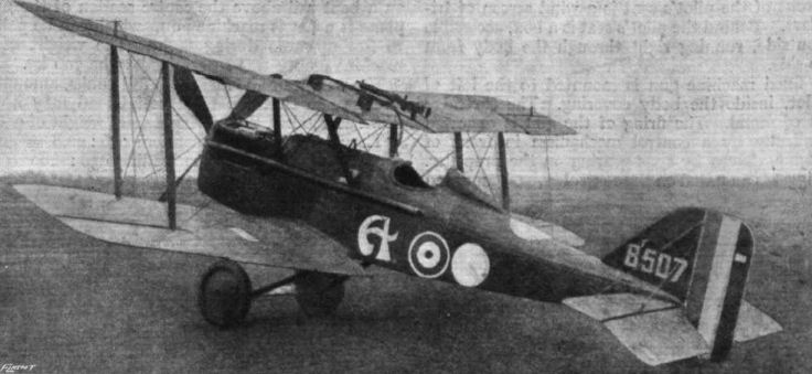
Three-quarter rear view of a S.E.5 Biplane, captured by the Germans.
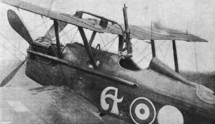
ENGLISH S.E.V.A. SINGLE-SEATER FIGHTER. - The front part of the body, with machine gun pointed upwards.
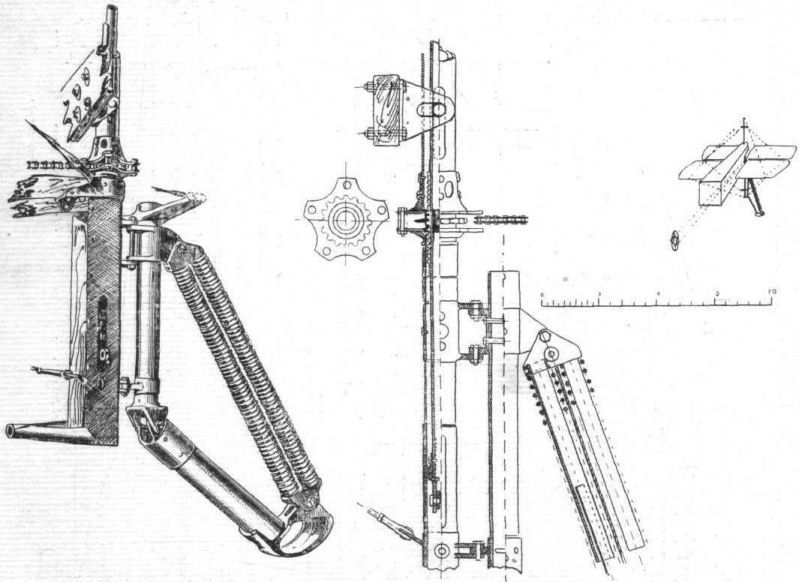
Elevator and variable tailplane arrangement, with steerable tail-skid of the S.E.
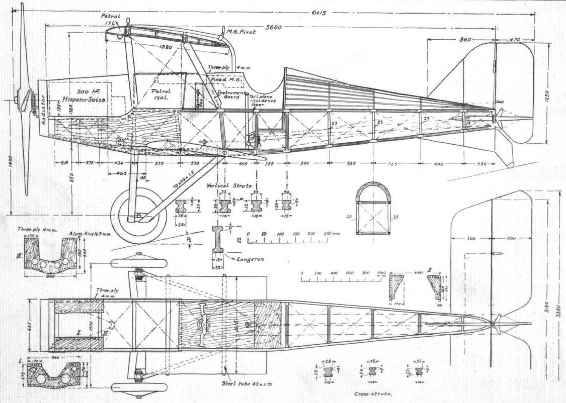
The English S.E.VA. single-seater fighter.
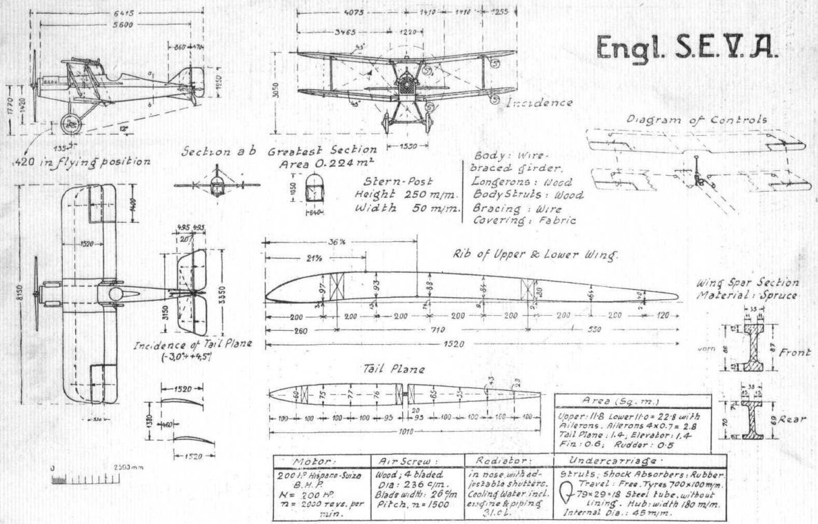
The English S.E.V.A. single-seater fighter.
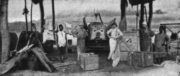
Assembling a Sunbeam-Coatalen "Short" waterplane in East Africa.
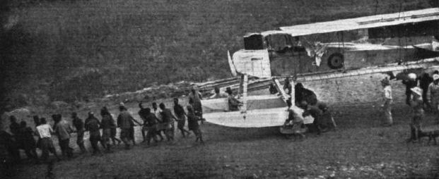
Launching a "Short" seaplane on Lake Tanganyika.
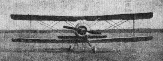
Some aeroplanes of the Fifth Army of France: Sopwith.
Flight, September 12, 1918.
THE SOPWITH "CAMEL."
130 H.P. CLERGET MOTOR.
[The following illustrated description of the Sopwith "Camel" has been translated from a German contemporary. - ED.]
THIS machine, built by the Sopwith Aviation Co., Ltd., of Kingston-on-Thames, carries the designation F.1 B. 6290. It is a single-strutter machine and is a development of the Sopwith "Pup," from which, however, it differs in many details, apart from the greater power of its engine.
As in the older type the wings and tail plane with elevator are of trapezoidal plan form, but the greatest span occurs at the trailing edge. The top plane centre-section has a span of 2.17 m., while the strut attachments are only 1.48 m. apart. As the petrol pressure tank and gravity tank are placed rather far aft, the pilot's seat is placed immediately behind the motor, underneath the top plane centre-section. In order to provide a better view, a rectangular opening is cut in the centre section. The longitudinal edges of this opening are provided with three-ply plates projecting beyond the wing profile so as to reduce the amount of air flowing over the edges. To facilitate getting into and out of the machine the trailing edge of the centre-section has been cut away. Upper and lower planes have an equal span of 8.57 m., and an equal chord of 1.37 m. The aspect ratio is therefore 6.25 against the aspect ratio of 5.15 of the older type.
The wing spars, which are made of spruce, are spindled out to an I section, with the exception of the bottom rear spar, which is left solid. The gap between the planes is 131 m. at the tips and 1.52 m. near the body. (In the older single-seater the gaps were 1 m., and 0.86 m. respectively.) The upper plane is staggered forward 0.45 m. There is no sweepback. The dihedral angle of the top plane is 178 deg. and of the bottom plane 170 deg. The angle of incidence of the top plane is 2 deg. at the centre-section, 3 deg. at the tip. The bottom plane has a uniform angle of incidence of 3 deg.
The inter-plane struts, which are of solid spruce of streamline section, are, as in all Sopwith machines, placed with their ends in steel shoes welded to the fittings on the wing spars, and are provided with no further attachment. The lift wires and landing wires, of which the former are in duplicate, are in the form of stream-line wires.
Non-balanced ailerons are fitted to the rear spars of both planes. The wing fabric, which is sewn on to the ribs, is cream coloured underneath, and the top surface, as well as the body fabric, is painted a redish brown. The body, which is of the usual girder type with four longerons, has a rounded top. The undercarriage is of the usual Sopwith type. A divided aluminium axle rests in a stream-line covering oа wood. The axle hinges are braced from the fuselage.
The tail plane, which is deeply cambered on both sides, is rigidly attached to the upper body longerons, with an angle of incidence of 1.5 deg. The tail plane trimming gear hitherto fitted to all Sopwith machines, has been abandoned, in spite of the fact that the petrol tanks are placed behind the pilot's seat. The fin and rudder are of the usual characteristic Sopwith form.
The 130 h.p. Clerget motor, which is built by Gwynnes, Ltd., develops about 134 h.p. at 1,200 r.p.m. According to a plate in the pilot's cockpit the revolutions of the engine are not to exceed 1,250 r.p.m.
The petrol pressure tank has a capacity of 138 litres and the gravity tank holds 32 litres. This gives sufficient fuel for a flight of about 3 1/2 hours' duration. An oil tank with a capacity of 30 litres is placed behind the engine. In some machines the tanks are of welded sheet aluminium, in others they are made of lead-coated, riveted sheet iron. The weight of the tanks is 12.5 kg. and 20 kg. respectively, giving a percentage weight of 12.5/146 = 0.0832 and 20/146 = 0.133 respectively.
In the pilot's cockpit are the following instruments, &c. :-
In the centre on the instrument board: Manometer, with safety valve, clock, pressure gauge, altimeter, compass, two switches, revolutions indicator, and pulsometer. On the right: The hand-pump (air). On the left: Control levers for pressure and gravity petrol tanks, petrol tap, throttle lever, petrol level indicator for pressure tank, Bowden cable for bomb release. A propeller air pump for the pressure tank is mounted on the starboard chassis strut. Two fixed Vickers guns are mounted on top of the fuselage. Their locks and feed block levers are inside the body covering. Between them is a telescopic sight. In a bomb rack under the body can be carried four bombst the Bowden controls for which are placed to the left of the pilot. There is no bomb sight fitted.
The weight of the machine empty was ascertained to be 430 kg. With tanks full the weight of the fuel is 150 kg. With pilot and armament the useful load would then amount to 290 kg. It is therefore to be assumed that the weight of about 50 kg. of bombs is only carried when the tanks are not full. Assuming a useful load of 290 kg. the total weight "all up" amounts to 720 kg. As the wing area is 19.76 m2, the loading is 36.5 kg. per sq m., and the loading per h.p. is 720; 134 = 5.37 lbs./h.p. The corresponding loadings for the Sopwith "Pup" were 23.4 and 6.6 respectively. The "Camel" has therefore a higher wing loading, but a considerably smaller loading per h.p.
Detail weights :- Motor, 159.0 kg.; airscrew, 18.0 kg.; tanks, 12.5 kg.; motor accessories, 12.5 kg.; body with aluminium covering, &c, 48.5 kg.; Seat, &c, 9.0 kg.; undercarriage, 39.0 kg.; tail skid, 2.5 kg.; controls, 4.5 kg.; wings, 100.0 kg.; tail plane, fin, rudder and elevator, 13.0, kg.; fittings for armament, 11.5 kg.; total, 430 kg.
Weight of wings. - 5.5 kg./sq. m.
Loading. - Pilot, 80 kg.; armament, 60 kg.; 4 bombs 50 kg.; instruments, 5 kg.; fuel, 150 kg.; total, 290 kg.
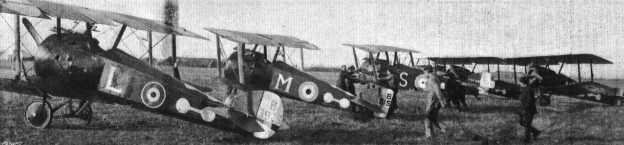
WITH THE BRITISH FORCES IN ITALY. - Scene at an aerodrome.
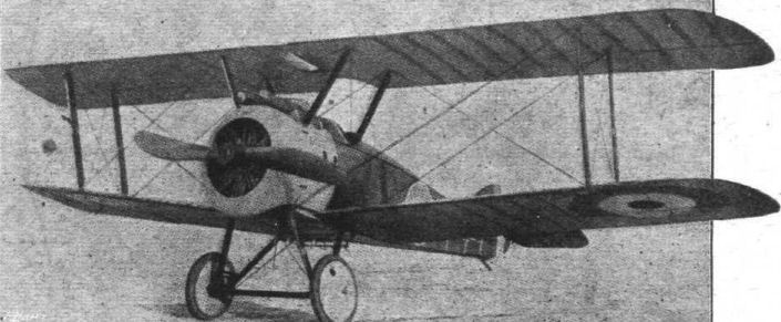
Three-quarter front view of the Sopwith "Camel."
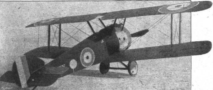
Three-quarter rear view of the Sopwith "Camel."
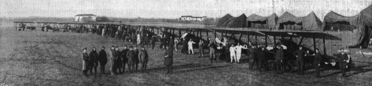
WITH THE BRITISH FORCES IN ITALY. - The squadron that has accounted for many Hun planes, lined up before departure.
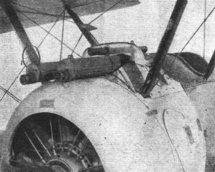
The arrangement of the machine guns and telescopic sight on the Sopwith "Camel."
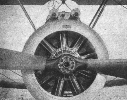
The 130 h.p. Clerget motor of the Sopwith "Camel," seen from the front.
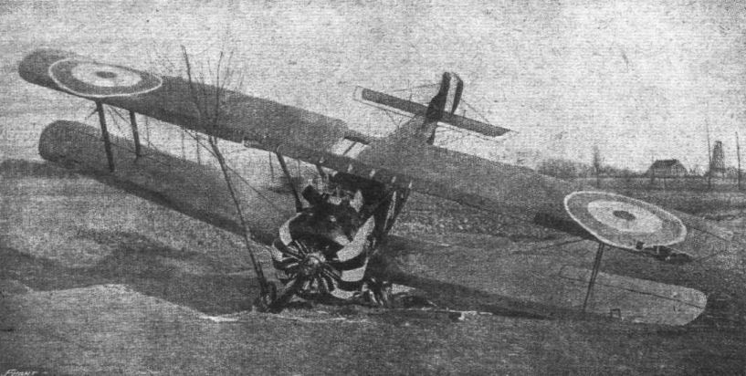
A Sopwith single-seater fighter shot down in an aerial fight on the Western Front. Note the peculiar painting on the engine cowl and the two fixed machine guns.
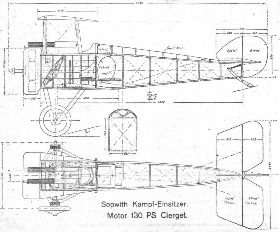
Side elevation and. plan of the fuselage of the Sopwith "Camel."
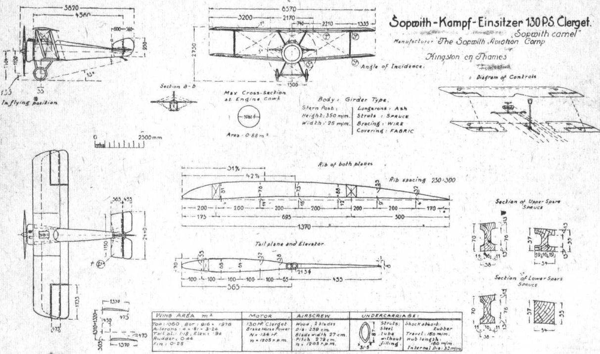
General arrangement, and some details, of tbe Sopwlth "Camel."
Flight, April 4, 1918.
THE SOPWITH TRIPLANE.
The following particulars of the Sopwith triplane are translated from German aeronautical journals, and we cannot, of course, vouch for the accuracy of the data given, nor can we, for obvious reasons, point out any mistakes that may be present. In spite of this, however, we have thought the following particulars of sufficient interest to include them in our series of descriptive articles on aeroplanes.-ED.]
IN Deutsche Luftfahrer Zeitschrift of August 22nd, 1917, Dipl. Ing. Roland Eisenlohr gives the following description of the Sopwith triplane: Among the new types of aeroplanes which the war has brought into being, the Sopwith occupies a unique position, as being the first triplane to be put into practical use. After some not very successful experiments in the earlier days of aviation, carried out in Germany by Hans Grade in 1907, in England by A. V. Roe, and in France by Goupy, this form of construction had fallen into disuse, and no great future prospects were anticipated for this type of machine.
What probably has led to the return of this form of construction is probably the small span which it enables one to use. Another advantage of the triplane arrangement is that the aspect ratio, which should not be less than 6, but which in many machines of short span often has to be considerably less, can be more easily arranged for in the triplane. Thus in the case of the Sopwith triplane the chord is only little over 1 metre, and the span is 8 metres. The increased wing resistance is counteracted by the employment of only one strut on each side and a very simple wing bracing. Furthermore it is possible, owing to the light loading of the wings, to construct the wing spars considerably lighter, and still have a comparatively great free length of spar, in the case of the Sopwith triplane about 2.75 m. with an overhang of 1.40 m. The weight of the total wing area will therefore scarcely come out greater than in the case of a biplane of the same area. Possibly also the arrangement of the wings is advantageous as regards the view obtained by the pilot, as the middle wing is about on a level with his eyes, and the upper and lower wings, on account of their small chord, do not obstruct the view to as great an extent as the wings of the ordinary smaller biplane having a greater wing chord. While both lift wires pass in front of the middle wing, the landing wire runs through it. The bracing cables for the body struts are crossed in the case of those running forward to the nose of the machine, while those bracing the struts in a rearward direction are straight. The gap between the wings is 90 centimetres, and the stagger is about 25 per cent. All the wings are fitted with wing flaps connected by a vertical steel band. In the nose the body carries a 110 h.p. Clerget rotary motor, enclosed in a circular cowl, which projects below the body in order to allow the air to escape.
The body is of rectangular section, rounded off in front by means of a light wooden framework in order to make it merge into the curve of the engine cowl. The width of the fuselage is 0.70 m., and it tapers to a vertical knife-edge at the back, to which the rudder is hinged. The elevator is in two parts, and has in front of it a tail plane of about 3 metre span, which, as in all Sopwith machines, can have its angle of incidence adjusted during flight.
The area of the Sopwith triplane is 27 square metres, so that for a total weight of 670 kilogs, the wing loading is only 25 kilogs. per square metre. With such a light loading the machine has undoubtedly a considerable speed and a very good climb. Further particulars relating to these have not yet been published up to the present. The triplane is built both as a single-seater and as a two-seater, and has always a fixed machine-gun in front above the fuselage, and in the case of the two-seater another machine gun operated by the observer. This increases the weight of the two-seater by about 100 kilogs.
The under-carriage consists, as in all Sopwith machines, of two V's of steel tubing and a divided wheel axle, the hinge of which is braced from the fuselage.
The following remarks are taken from the Flugsport :-
The fuselage with tail plane and rudder is the same as that of the small Sopwith single-seater biplanes. The three wings have a span of 8.07 m. and a chord of 1 m. The lower and middle wings are attached to short wing sections on the fuselage. The upper plane is mounted on a canopy [the German term for a small centre section supported by struts from the body-ED.]. Both spars of the upper wing are left solid, while those of the lower and middle are of I-section. The interplane struts, which are of spruce, and of streamline section, run from the upper to the lower wing, and the inner ones from the upper wing to the bottom rail of the fuselage. In order to give a better view the middle wing, which is on a level with the pilot's eyes, is cut away near the fuselage.
The wing bracing is in the form of streamline wires of 1/4-in. diameter. The very simply arranged landing wires are in the plane of the struts, while the bracing of the body struts, as well as the duplicate lift wires, are taken further forward. From the rear spar of the middle wing, wires are run forward and rearward to the upper rail of the fuselage, and the lower wing also has a wire running forward to the lower rail of the body. All the planes have wing flaps, and inspection windows of celluloid are fitted over the pulleys for the wing flap cables.
The motor is a 110 h.p. Clerget, and the petrol is led to the engine by means of a small propeller air pump mounted on the right hand body strut. As the air screw was not in place we cannot give details of it. In the pilot's seat were the following instruments :- On the right a hand wheel for varying the angle of incidence of the tail planes, a hand operated air pump, and a petrol indicator. In the middle air speed indicator, manometer, clock, revs, indicator, and switch. On the left a petrol tap, lever for regulating the air, and lever for regulating the petrol. The weight of the machine empty was found to be 490 kilogs., and if the useful load is assumed to be 200 kilogs., we obtain a total weight of 690 kilogs., which, with an area of 21.96 sq. metres, would give a loading of 31.4 kilogs. per square metre.
Further, the following particulars are given :- Motor: Clerget, nominal h.p. 110, brake h.p. 118; fuel capacity for two hours, petrol 85 litres, oil 23 litres; area of wings and flaps (square metres), upper 7.90, middle 6.96, lower 7.10, total 21.96; area of elevators 6 by .5, of wing flaps 1.10, of rudder .41. Angle of incidence (degrees): upper wing, root + 1, tip - .8; middle, root + 1.5, tip + 1.5; lower, root +.5, tip - .5; tail plane, variable + 2 to - 2 degrees. Loading per sq. metre, empty 22.3, fully loaded 31.4; loading per brake h.p., empty 4.15, fully loaded 5.85.
Weights.
Fuselage with under-carriage and accessories 123. 5 kilogs.
Wings 135
Tail plane, rudder and elevator 13
Engine 160
Petrol tank 15
Oil tank 8.5
Propeller 16
Engine accessories 16
Mounting 3
--- All 490
Pilot 80
Gun and ammunition 40
85 litres of petrol and 23 litres of oil 80
--- All 200

Three-quarter front view of the Sopwith triplane.
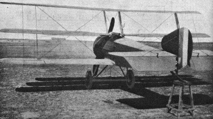
Rear view of the Sopwith triplane.
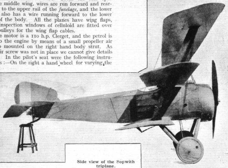
Side view of the Sopwith triplane.
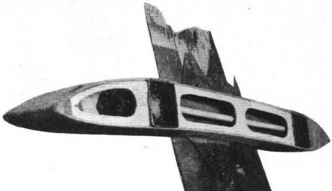
Attach merit of middle wing to body strut on the Sopwith triplane.

Interplane strut attachment to middle wing of Sopwith triplane.
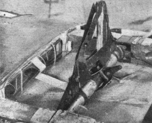
Attachment of interplane strut to lower wing on the Sopwith triplane.
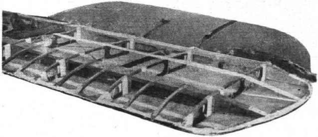
Middle wing of the Sopwith triplane.
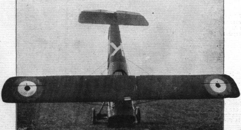
THE END OF THE JOURNEY. - A Sopwith triplane in the hands of the enemy.
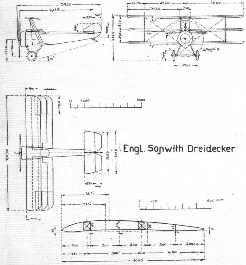
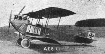
A CI type
Flight, June 6, 1918.
REPORT ON A.E.G. BOMBER, G. 105.
[Issued by the Technical Dept. [Aircraft Production), Ministry of Munitions.]
THIS machine was brought down by anti-aircraft fire at Achietle-Grand on December 23rd, 1917.
On a label protected by celluloid, mounted on a tube in the nacelle, is the legend - "Abnahme am (Accepted on) November 10th, 1917."
This machine, whilst carrying a similar power plant, is very different in construction from the Gotha type, which also embraces the Friedrichshafen Bomber reported on in I.C. 619.
Whereas the latter is generally constructed of weed, ply wood being used to a very large extent throughout, in the A.E.G. steel is almost universally employed, not only in regard to the fuselage, nacelle, subsidiary surfaces and landing gear, but also in the wings themselves.
Needless to say, acetylene welding is freely resorted to throughout the construction, which, however, appears to be far from light.
On the whole, the A.E.G.-aeroplane, judged by contemporary British standards of design, is decidedly clumsy, not only in detail work, but also in appearance. The performance is poor.
The leading particulars of the machine are as follows :-
Weight empty 5,258 lbs.
Total weight 7,130 lbs.
Area of upper wings 395.2 sq ft.
Area of lower wings 335.2 sq.ft.
Total area of wings 730.4 sq. ft.
Loading per sq. ft., wing sur. 9.77 lbs. per sq. ft.
Area of ailerons, each 17.9 sq. ft
Area of balance of aileron 1.8 sq.ft.
Area of tail plane 34.0 sq.ft.
Area of fin 11.5 sq. ft.
Area of rudder 20.8 sq. ft.
Balanced area of rudder 2.6 sq. ft.
Area of elevators 31.2 sq. ft,
Balanced area of elevators 3.6 sq. ft.
Horizontal area of body 206.4 sq. ft.
Vertical area of body 209.2 sq. ft.
Total weight per h.p. 13.7 lbs. approx.
Crew - Pilot and two passengers 540 lbs.
Armament 2 guns
Engines 2 260 h.p. Mercedes.
Petrol capacity 123 galls. = 861 lbs.
Oil capacity 11 galls. = 110 lbs.
Water capacity 13 galls. = 130 lbs.
Other dimensions are also shown on the drawings on page 612.
Performance.
(a) Climb, 5,000 ft. in 10.3 minutes. - Rate of climb at 5,000ft. - 390 ft. per minute. Climb, 9,000 ft. in 23.4minutes. Rate of climb at 9,000 ft. - 235 ft. per minute.
(b) Speed at Heights. - Level to 5,000 ft. - 90 miles per hour approximately. At 9,000 ft. - 86 miles per hour approximately.
(c) Landing Speed. - The aeroplane is best landed at a speed between 75 and 80 miles an hour; after flattening out it sinks to the ground quickly and pulls up rapidly.
(d) Control. - 1. Lateral - Good. 2. Elevators - Bad, especially when landing.
NOTE. - It is stated that it is not advisable to fly this machine without a passenger in the front seat.
Construction.
Wings.-As will be seen from the scale drawings, the wings are of characteristic form. The central portion consists of a rectangular centre cell permanently attached to the fuselage. The lower wings support the engines. In this centre cell the planes are set horizontally. At each side of it the lower main planes are swept upwards with a vertical dihedral of 2.75°, the top planes being kept flat, and both main planes are swept backwards in the horizontal plane to an angle of 4° for the bottom plane and 3° for the top plane. As, the central portion of the upper main plane has 4 ins. of negative stagger relative to the bottom plane, this difference in angle brings their tips practically vertically over one another. The angle of incidence attains a maximum of 4° at the base of the engine struts, i.e., 7 ft. 10 3/8 ins. from the centre. At the second strut the angle is 3 1/2°, and at the end strut 2 1/2°. These angles are painted in circles on the surface of the planes, evidently for the convenience of riggers. The camber of both planes is washed out gradually towards the tips, and a representative section of the main planes taken at the junction of the engine bearer struts is given in Fig. 1. For purposes of reference the R.A.F. 14 section is superimposed. This figure also shows the position of the main spars, which are of steel tube. These are 50 mm. in outside diameter, but their wall thickness is not at present known. In order to allow the thinning down of the wing section, these tubes are flattened out towards the extremity of the wing. They are chamfered down to a narrow end and a fiat plate acetylene welded on to each side; thus at the spar tip the section is roughly rectangular. The main spars are kept parallel throughout the whole of their length, and are attached to the central cell by means of pin joints, similar to those on the Friedrichshafen. The ribs are of solid wood and are constructed as shown in Fig. 2. It is rather notable in comparison with other German machines of all types that ply wood is almost entirely absent. In the A.E.G. construction the rib webs are perforated and strengthened by wooden uprights at intervals and are glued into a grooved flange. The ribs are placed 300 mm. - 325 mm. apart and are not directly or firmly attached to the spars on which they are a relatively loose fit. Passing through the ribs of the bottom plane and extending from their junction with the centre section to the extreme outside strut are two steel tubes, approximately 17 mm. in diameter, which act as housings for the aileron control wires. These tubes are very strong, and it is thought possible that they are also counted upon to lend rigidity to the wing structure. The leading edge, which is of the usual semi-circular section, acts as a distance piece, as also does the wire trailing edge. Thirteen inches in front of the last named is a stringer formed of a steel rod. Apart from this, the spars are the only longitudinal members of the wings. Between the main ribs are false ribs running from the leading edge to a point a few inches behind the leading spar and applying only to the upper surface. One of these false ribs is sketched in Fig. 3. It is secured as shown in the sketch by means of a semi-circular saddle and a wrapping of tape which passes as shown through holes in the rib. Where it meets the leading edge it is furnished with triangular packing pieces, which locate and hold it in position. The lower plane is covered as to its upper surface with sheet metal immediately under the engines, whilst between them and the fuselage is fixed a strip of corrugated aluminium which acts as a footway. The fabric is attached in the usual manner, and is stitched to the ribs both top and bottom. The two surfaces are stitched together behind the metal rod, which acts as a stringer, and by this means the actual trailing edge wire is relieved of a certain amount of tension. The wing structure is internally braced by means of steel tubular cross-pieces and stranded cables. A single fitting is employed for the attachment of the interplane struts and for that of the bracing tubes. This fitting is shown in Fig. 4. It is a tight fit on the spar, to which it is fixed by a bolt, and is formed with an extension lug which acts, as shown, as an anchorage for the bracing tube, whilst a sideways extension of the same lug carries an eye for the bracing wire. It is provided with a cup-shaped upper extension, into which there is screwed a steel dome which carries the ball of the strut socket fitting and also acts as a wiring plate for the interplane bracing wires. As shown in the sketch, the fabric is run into the space between the upper and lower flanges of this fitting, the whole making a very neat job.
Struts.
These are of streamline section steel tube and of uniform dimensions throughout. The section is 92 mm. long by 48 mm. broad. The ends are sharply tapered down, and into them is welded a cupped ferrule which drops on to the ball shown in sketch Fig. 4, and is there held in position by a cotter pin. The attachment is shown complete in Fig. 5. This joint gives a considerable range of lateral freedom, as is the usual practice on machines of German design.
Fuselage.
The whole of the fuselage is built up of steel tubes welded together. It is of plain rectangular section, and the cross tubes are attached directly to the main booms without the intervention of any clips. This detail of construction is shown in Fig. 6, which also illustrates the single and double lugs which are used for the purpose of securing the bracing wires. Under the nacelle and in the neighbourhood of the main petrol tanks and the bomb racks the fuselage is reinforced with thin tubular steel tie-rods. Fig. 7 shows the manner in which the upper booms of the fuselage are provided with sockets for the inclined struts of the central cell. The fitting consists of two circular steel plates welded into position to form an integral part of the frame joint, the front one of these flanges being provided with lugs for the anchorage of bracing cables. The inclined struts are secured by a ring>of short set screws wired together as shown. If appearances are to be trusted, this form of attachment, whilst being strong and convenient, is excessively heavy. Unlike the practice which is pursued in the Friedrichshafen Bomber, wherein the main frame consists of three separate sections, that of the A.E.G. is in one piece from stem to stern. The longerons are 30 mm. in diameter and the transverse members 30 mm., these dimensions being retained up to the extreme tail end. The nose part of the frame is covered-in with three-ply wood, but behind this a double covering of fabric is used, under which the tubular construction is completely hidden. Behind the after cockpit a single covering only is adopted and laced the whole of its length so that it is removable in its entirety.
Engine Struts.
These are of streamline steel tubing and embrace joints of a somewhat similar type to those used on the interplane struts; that is to say, a certain amount of free movement is provided. The mounting of the engines is clearly shown in the front and side elevations. In front there are four struts which converge to a joint on the leading spar, whilst at the rear there are two struts which meet at a joint on the trailing spar. The attachment of the former is shown in Fig. 8. The bell-shaped housing attached to a cup on the spar joint contains a ball-end set screw which screws into the foot of the four struts which are here united by welding. The inclined transverse struts are taken from the spars to the engine mounting and cross struts from thence again to the upper booms of the fuselage. In order to provide simplicity of erection these subsidiary struts are provided with a means of adjustment as shown in Fig. 9. At one end they terminate in a ball-ended set screw screwed into the tapered end of the strut and secured by a lock nut.
Engine Mounting.
The engine bearers are of steel rectangular section, measuring 40 mm. high by 30 mm. broad, with a wall thickness of approximately 2 mm. These bearers are welded to the struts which support them, as shown in Fig. 10, and for the greater part of their length are reinforced by a system of tubular tie-rods also welded in position. Box attachments welded to the engine bearers, as shown in Fig. 11, are provided for the crank-chamber holding-down bolts. The engine is not directly mounted on the steel bearers, but upon 1/2-in. wooden washers. Owing to the deformation inseparable from so much welding the engine mounting is of very clumsy appearance, and, in act, the quality of welding does not appear to be up to previous German standards, but the construction would appear to be light.
Engine Fairing.
As shown in the photographs, the engines are almost completely enclosed in a fairing composed of detachable aluminium panels. The necessary framework and clips are provided for panels totally enclosing the engine, but it would seem that this bonnet right over the heads of the cylinders has been discarded. The tubular framework which supports the panels is an elaborate piece of work comprising a multiplicity of welded joints. It consists of 16 mm. tubes, to which are attached lugs for carrying the necessary turn-buttons. The framework is made in two halves so as to be easily detachable, and a joint for that purpose is made, as shown in the sketch Fig. 12. It will be noticed that a narrow slot for the exit of air passing over the engine is provided at the rear end of the engine egg, an opening of somewhat similar dimensions being between the two halves of the radiator.
Engines.
The engines are the standard 6-cylinder 260 h.p. Mercedes. These engines have already been fully described, and no important novel points are adopted. A new shape has been adopted for the exhaust pipe, and this is clearly shown in one of the photographs - an inverted cone is placed in the belled mouth of the pipe. The usual water pump greaser is fitted and worked by a lever in the pilot's cockpit. It is of rather less clumsy design than that of the Friedrichshafen, but employs the same principle. The throttle is interconnected with the ignition advance as described in the Friedrichshafen report. A small fitting, the purpose of which is not very clear, is attached to the carburettor, and consists, as shown in Fig. 13, of a bell-shaped cover over the top of the float chamber, not directly connected thereto, but supported on a bracket clipped to the main water pipe. The bell is free to slide up and down the stem of the bracket, on which it is a very loose fit, but is prevented from falling over the float chamber by a small washer. It is conjectured that this fitting may have for its purpose the prevention of petrol having access to the hot exhaust pipe in the event of the machine turning over. Between the bell and the float chamber is a clearance of about 1/4 inch.
Petrol System.
The petrol system employed on the A.E.G. is as set out diagrammatically in Fig. 14. There are two main tanks, each of 270 litres = 95 gallons total capacity, and these are placed tinder the pilot's seat in the main cockpit. Two subsidiary tanks used solely for starting purposes and giving a gravity supply are mounted in the centre section of the top main plane and are of roughly streamline form. Beneath them is a small cowling containing their level gauges, which are visible from the pilot's seat. On the right hand side of the main cockpit is fitted a hand-operated wing pump, the object of which is to draw petrol from either of the main tanks and direct it to the gravity tanks. Pipes from all four tanks are taken to a distributing manifold on the dashboard, and by means of seven taps thereon the supply of petrol can be directed from any one of the tanks to either engine or both. Two additional taps are provided on the wing pump so that the fuel for the gravity supply can be drawn from either main tank as required. The photograph A clearly shows the arrangement of the petrol taps, which are of the plain plug type. It would appear that the troubles associated with this form of tap have been overcome, as they show no signs of leaking or sticking. The level of the main tanks is indicated on the dashboard by two Maximall gauges. Those attached to the gravity tanks are made by Laufer, and employ the static head principle. They read up to 45 litres each, from zero to this figure being given by one and a half complete revolutions of the indicating hand.
Petrol Pressure System.
The sketch, Fig. 14, also shows in solid lines the arrangement of the petrol pressure system. The usual pressure pump is mounted on each engine, and pipes therefrom are led to a manifold mounted on the dashboard. This is also connected to a large hand pump on the right hand side of the pilot's seat. Gauges reading the pressure from each engine pump are provided, and there is also a blow-off tap for relieving the pressure of the whole system.
Oil System.
This is the usual system as fitted to all 260 h.p. Mercedes engines. The main supply of oil is carried in the crank chamber sump and is continually being refreshed by a small additional supply of fresh oil drawn from an external tank. This tank has a capacity of 5 gallons, is of rectangular shape, and is mounted at the side of the engine nearest to the fuselage. It is provided with a visible glass level, over which is a celluloid covered window let into the engine fairing, so that the oil level is visible from the pilot's seat.
Radiator.
Each radiator is composed of two halves bolted together, as shown in the sketch Fig. 15, which is to scale. The space between the two halves is partially covered with a sheet metal panel pierced with a hole 1 ft. 6 ins. high by 4 ins. wide. The radiator is not actually honeycomb, though representing that appearance. It consists of a series of vertical tubes with transverse gills. Each radiator cell measures 2 ft. 3 1/2 ins. high by 7 1/2 ins. wide, and has a uniform depth of 4 ins. Each complete radiator is provided with two shutters of roughly streamline section. These, when fully closed, cover over about one-third of the radiating surface.
They are controlled from the pilot's seat by two levers shown in Fig. 16, which work them through universally jointed rods. The articulation in these rods is very neat and of the form shown in sketch Fig. 17. Each radiator is fitted with an electric thermometer, full details of which device have been published. The dial of this instrument is carried on the dashboard and is furnished with a switch enabling the temperature of either radiator to be independently read.
Engine Control.
The throttle levers are of the plain twin variety, and are constructed as indicated in sketch Fig. 18. They are placed close together so as to be easily worked either in unison or separately. The connections between the levers and the carburettor are made as simple as possible, and the levers operate the throttle through a couple of universally jointed rods which extend from each side of the body to the engine eggs. The universal joints used are of the type shown in Fig. 19, there being apparently no particular desire on the part of the designer to economise weight in these details.
(To be continued.)
Flight, June 13, 1918.
THE A.E.G. BOMBER, G. 105.
[Issued by the Technical Dept. (Aircraft Production), Ministry of Munitions.]
(Concluded from page 616.)
Tail Planes.
THE fixed horizontal tail planes are notable for their extremely bold curvature, both top and bottom. The framework consists entirely of welded steel tubing. The leading edge of the tail plane is mounted so as to be adjustable in case of necessity, a simple bracket being used for this purpose, as illustrated in Fig. 20. This is welded on to the fuselage upright at each side and strengthened with a transverse stay. It allows the tail plane leading edge to be fixed in one of three positions. The trailing edge of the tail plane is supported each side by a streamline section steel tubular strut.
Fin.
The fin, like the fixed tail plane, has also a very strongly marked streamline section at the base tapering off to flat at the top, where it abuts against the balanced portion of the rudder. At this point its framework, which is of light steel tube, is made rigid by a couple of tubular stays bracing the rudder post to the sides of the fuselage.
Rudder and Elevators.
These organs are built up of steel tubular framework, and present no points of special interest, except that in the case of the rudder that part which is above the fixed fin is made of grooved section.
Ailerons.
As may be seen from the plan view of the complete machine, the shape of the ailerons is somewhat unusual. These are applied to the top plane only and have a chord which reaches its maximum at their extreme ends and its minimum in the centre of their length. For what purpose this peculiar shape is adopted is not clear. The framework of these ailerons is welded steel tubing, and the control crank is fitted in such a way as to lie partially hidden in a slot in the main plane. This crank is built up of welded sheet steel, and is arranged as shown in the sketch. Fig. 21, an elliptical hole being cut in the trailing edge of the main plane for the passage of the forward wire.
Control.
The main control consists of a wheel mounted on a pivoted lever, the wheel operating the ailerons by means of a drum and cables, which pass direct over pulleys and along tubes running parallel with the wing spars and then over inclined pulleys up to the aileron cranks. The wheel column is pivoted to a long crossbar extending the whole length of the fuselage and carrying at each end cranks for the elevator control wires which at intervals are carried through fibre guides socketted to the frame. The cranks of the elevators are concealed inside the rear end of the fuselage, whilst those of the rudder (which is fitted with duplicate cranks and wires) are external. A modified dual control is fitted, which allows the assistant pilot to work the elevator and rudder only. For this purpose a socket is mounted on the pivot bar into which can be inserted a plain steel tube which is normally carried in clips behind the pilot's back. A second rudder bar, the design of which is shown in Fig. 22, is carried under the dashboard, and can readily be dropped into position into a square socket partially sunk into the floor of the cockpit and connected to the pilot's rudder bar by cranks and a link.
Personnel
Seats are provided for a crew of four, who are carried as follows :- One in the front cockpit; one in the pilot's seat; one at the pilot's side; one in the rear cockpit.
All can, if necessary, change places whilst the machine is in the air. Between the front cockpit and that of the pilot a sliding panel is provided through which the gunner can crawl. The seat at the side of the pilot folds up and slides back into a cavity under the coaming of the nacelle, and when in this position allows access down a narrow and inclined passage-way to the rear cockpit. The machine can hardly have been designed to satisfy the requirements of the average pilot in regard to view, as from the pilot's seat it is very difficult to see the ground properly on account of the position of the lower main plane and the width of the fuselage.
Armament.
Two Parabellum guns are mounted, one in the front cockpit, and one in the rear, and provision is made for mounting a third or for transferring one of the others on the floor of the rear cockpit, so that it can fire backwards and under the tail of the machine. For this purpose a large trap door, which is visible in the photograph B, is provided in the floor of the fuselage behind the rear cockpit. This trap door has celluloid windows and is normally kept closed by springs. It is lifted up by a small hand winch fitted with a ratchet. It is of passing interest to note that whereas in the Friedrichshafen a similar trap door was kept open by means of springs, in the A.E.G. springs are used to keep the door closed. In the front cockpit the gun is supported on a carriage which runs round a partially circular rail which is strongly supported from the fuselage by a framework of steel tubes. Forming part of this frame is an inclined steel tubular column, the base of which is fitted in a swivel bearing in the floor of the cockpit, and on this is mounted an adjustable seat for the gunner. A toothed rack runs round the rail and engages with a spur pinion driven by a hand wheel so that the gunner, when occupying his seat, swivels himself round as well as the gun. This gun mounting is shown in photograph C, and a diagrammatic section of the carriage is given in Fig. 23. The vertical swivel of the fork-ended gun carrier is locked by a ball-ended lever and a similar lever is employed for locking the carriage itself to its rail.
This action is accomplished by a cam device which depresses the roller of the carriage and squeezes the rail section between the roller and an adjustable set screw which normally just clears the groove on the under side of the rail. In order to prevent the forward gunner from shooting the tractor screws, preventative shields of light steel tube are carried between the upper edge of the forward cockpit and the inclined struts of the centre section. These impose a limit to the travel of the gun. In the rear cockpit the gun mounting is U-shaped in plan form, and here again the principle of a carriage running on a rail and driven by a spur gear meshing with a toothed rack is employed, though in this case the gunner's seat does not revolve with the gun. The carriage is of a somewhat similar type to that used in the front cockpit, but the method of locking it is different. This is shown diagrammatically in Fig. 24. The rail is provided with grooves both above and below, there being two rollers at the top and one underneath. Normally, when the gun carriage is free, the latter is clear of the rail, but when the locking mechanism is brought into action it is forced upwards so that the rail is gripped between the rollers, thus avoiding any possibility of shake at this point, and at the same time a positive lock is obtained on a second rail carried below the first. When the ball-ended hand lever is tightened, its effect is to squeeze the lower rail between two jaws. The movable jaw is, however, connected up by a link to a small cam, the base of which abuts against the foot of a fork-ended rod which carries the lower roller and is free to move up and down in a guide, to the base of which the cam is pivotted. By this means a very secure and rapid locking device is obtained. In the front of the rear cockpit a locker is provided which would be capable of holding ammunition, and beneath this a series of racks of the type shown in Fig. 25. These racks are not strong enough to hold anything very heavy, and are placed approximately 5 ins. apart. Their exact purpose is not known.
Bombing Gear.
Three racks for holding twenty-five pounder bombs are installed on the machine: two side by side on the left side of the rear cockpit, and one on the right side of the petrol tanks in the space between the pilot's and rear cockpits. This rack is covered by a detachable wooden lid which acts as the floor of the narrow gangway mentioned above. Underneath the centre of nacelle provision is made for carrying two or more large bomb racks, which, however, were not in use on this machine. Underneath the lower main plane, two at each side of the nacelle, are fixed bomb clips which are capable of supporting bombs roughly 8 inches in diameter. They are held in position by a belly-band consisting of two steel strips, clearly shown in the photograph B. Eleven and a half inches in front of this clip is a bracket suitable for a circular section of 4 inches in diameter, and 13 1/2 inches in the rear of the clip is a second bracket suitable for a 5-ins. diameter section. The bomb would thus appear to be 50 kgs. In the photograph the belly-bands are shown clipped out of the way. At their fixed end they are supported on a crosshead, a sketch of which is given in Fig. 26. This in turn is carried on a bracket clipped to a steel tube running parallel to the wing spars and braced thereto by tubular steel girders. The cross head is free to swivel on the bracket against the action of a coiled spring which, when the bomb has been released, twists the crosshead round against a stop, so that the belly-band is forcibly swung round and now faces the direction of flight instead of lying edgewise on to it. The ends of the steel strips are swivelled on the crosshead, and here again coil springs are used, so that the tendency is for the belly-band to be held flat against the lower surface of the bottom main plane, and out of the way of the other clip.
When the bombs are in position, the rings which are fitted on the free end of the belly-band are caught between the jaws of a trigger mechanism, illustrated diagrammatically in Fig. 27. This device is carried on the same tube which supports the crossheads, as already mentioned. Lying parallel to this tube and between it and the leading spar is a control rod fitted with two levers which are connected respectively to the two bomb trip gears, and this rod is operated by a quadrant lever mounted in the front cockpit. In order to allow one trip gear to be worked at a time, the link of the outer trip is provided with a slot where it is pivotted to the trigger release. On working the lever in the cockpit, therefore, its first action up to half way over the quadrant is to release the bomb nearest the nacelle, whilst a further movement releases the outer bomb. An exactly similar method is employed for operating the bombs carried underneath the other wing. The levers in the front cockpit are all mounted on a common bracket built up of steel tubes, and are arranged as follows :- First, there are the two levers which control the two bomb magazines in the rear cockpit. These are provided with thimbles and chains, so that they cannot be operated accidentally. Next, a single lever which controls the larger bomb clips on the right wing. These are capable of being secured by split pins inserted in their quadrants. Next, there is a lever which in this particular machine was furnished with no action at all, but is evidently designed for manipulating the large bomb-carriers when these are installed. Behind it are, first, a single lever for the left hand outer bomb clips, and, finally, the lever for working the bomb magazine on the right hand side of the nacelle.
Landing Gear.
The landing gear of the A.E.G. bomber is simply an elaboration of that which has become practically a standard fitting on single and two-seaters, except that in this machine the gear is in duplicate. It consists of two axles carrying two wheels a-piece, and suspended from pairs of V struts. One pair is connected to the spars of the centre section immediately underneath the engine strut sockets, and the other to the spars midway between this point and the fuselage and at the same point from which diagonal struts are taken from the spars to the engine mounting and nacelle. This, together with the wire bracing of the landing gear struts provides a completely triangulated construction. The struts are, however, connected by ball joints similar to those used with the engine struts, so that in case of strain a certain amount of free movement can take place. The pairs of V struts carry at their foot a hollow steel crossbar having the section of a trough, and in this lies the axle which connects the two wheels. As shown in the sketch Fig. 28 and in the photograph D, the fixed beam has forward and rearward extensions, at each end of which are anchored the ends of the batteries of coil springs which act as shock absorbers, and at their other ends are hooked to a horn plate on the wheel axle. Each battery of springs, of which there are four to each axle, consists of 18 springs. A yoke of stranded steel cable restricts the movement of the axle beyond a certain limit. The tyres are 32 ins. x 6 ins. - 810 x 150. A tail skid of massive proportions is used. This is of the shape shown in photograph E, and is built up entirely of welded steel. The springs against which it works are concealed inside the tail end of the fuselage.
Wireless.
The machine is internally wired for wireless, and a special dynamo for supplying current for this purpose and also for heating is installed on the right hand engine. This dynamo bears the following inscription :-
Telefonken;
J. P. Flieg. C 1916. Type D.
Alternating current 270 watts. 5 ampAres. 600 frequency.
Continuous current 50 volts. 4 amperes, r.p.m. 4,500.
The dynamo is mounted on brackets acetylene-welded to the steel engine bearers, and is normally completely enclosed in a detachable fairing. Its position is clearly shown in photograph F. The dynamo drive embraces the pulley which is a standard fitting on the 260 h.p. Mercedes, but in this particular case the clutch gear whereby the driving pulley can be disconnected from the engine as required appears to have been discarded. Two sets of wires are taken from the dynamo inside flexible metal conduits to a pair of plugs situated at the junction of the fuselage and the right hand lower main plane. Here they terminate in plug sockets, so designed that the plugs cannot be inserted wrongly. One of these wiring circuits applies to the heating system, and wires for this purpose are carried to points in all three cockpits, whilst the other circuit is for wireless and terminates in a plug adapter in the rear cockpit. No wireless instruments were fitted. Two plug sockets for the heating installations are arranged in the rear cockpit; two in the pilot's cockpit and one for the forward gunner. A small plate on the pilot's dashboard carries the following inscription, but no definite information is given :-
F. T. Fitting. W/T Set.
Aeroplanes.
Type 94. NY 1125/16.
Fitting, No. 85A.
Driving propeller. Type. Direct coupling.
Length of aerial wires - - -
Telefunken transmitter.- - - metres.
Huth transmitter, - - - - metres.
D transmitter - - - metres.
G transmitter - - - metres.
In addition to these two circuits, there is a lighting installation in conjunction with a battery carried in a box in the rear cockpit. From here, wires are taken to each cockpit and also to the tail and via the leading edge of the upper plane to the extreme outside strut of each wing. On these struts red and green lights are carried, the lamps for this purpose taking the form shown in. Fig. 29. Inspection, lights, are provided, at convenient points in each cockpit over the dashboard, instruments, &c.
For the most part the lighting wiring is contained inside a light celluloid conduit.
Instruments.
These comprise twin engine revolution counters, twin air pressure gauges for the petrol supply, electric thermometer, altimeter, petrol level gauges, &c. All of these are of recognized types and call for no detailed description.
Camouflage.
This machine is camouflaged in six different colours, on a uniform system covering every portion. The colours are arranged in hexagons measuring roughly 18 ins. across the flats, and the colours are sage green, reddish mauve, bluish mauve, black, blue and grey. These colours are not flat washes, but are softened by being stippled and splashed with paint of a lighter tone. The effect gained is well shown in photograph G. Considerable care appears to have been taken with this camouflage scheme, which is presumably effective.
Fabric and Dope.
The fabric throughout is of good quality, and the dope acetate of cellulose.
Propeller.
Diameter 10 ft. 3.8 ins. + .20 in. Pitch 59.3 ins.
The following table gives the thicknesses of the various laminae used in construction of the air-screw. The laminae are numbered from the trailing to the leading edge :-
Thickness
No. Material in inches.
1 Walnut 0.73
2 Mahogany 0.80
3 Mahogany 0.80
4 Mahogany 0.80
5* Mahogany 0.80
6 Mahogany 0.80
7* Mahogany 0.40
8* Mahogany 0.40
9 Mahogany 0.80
10 Walnut 0.83
* These laminations were of a quite different kind of mahogany, probably African.
Only one air screw has been seen and dimensioned. Thus it is unknown whether all air screws would have laminae of similar thicknesses and of similar timbers. There is no apparent reason why these laminae should be of different thicknesses. It is surmised that either the enemy is short of timber or that he has a highly scientific reason for so doing that we do not know. The port and starboard air screws rotate in opposite directions.
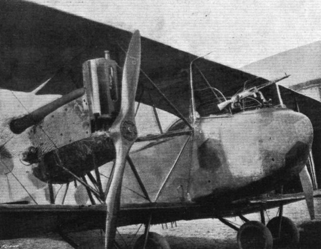
J. Three-quarter front view of nacelle and engine egg.
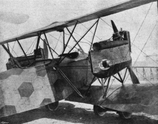
F. Three-quarter rear view of fuselage and engine mounting.
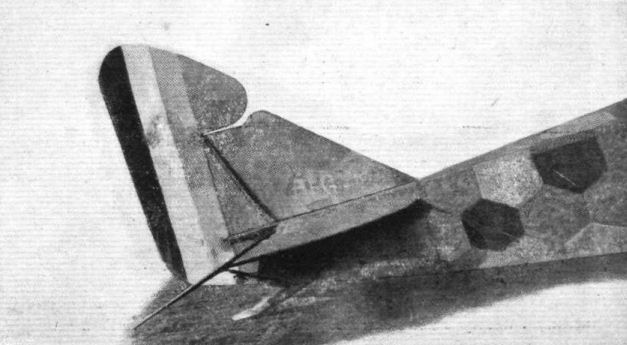
E. Arrangement of tail.
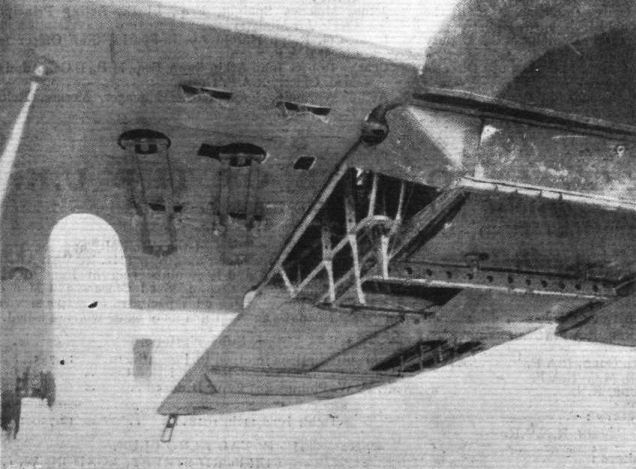
B. Underside of the nacelle showing bomb magazines and racks, also trap-door in rear cockpit.
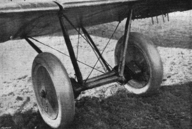
D. Undercarriage.
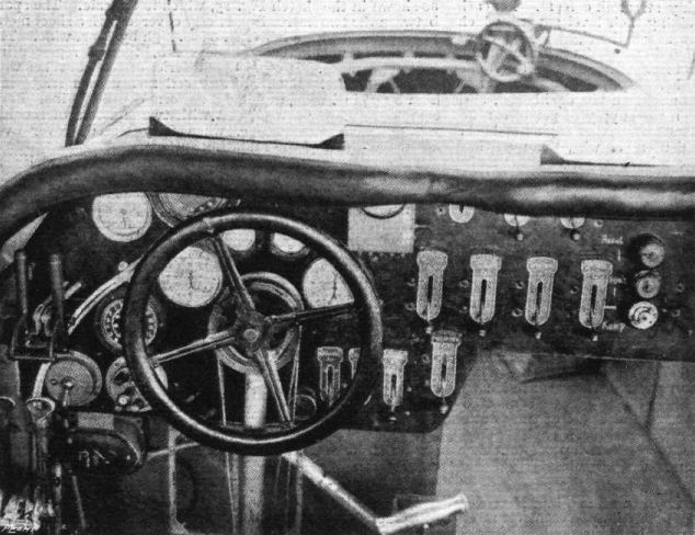
A. Instrument board in pilot's cockpit.
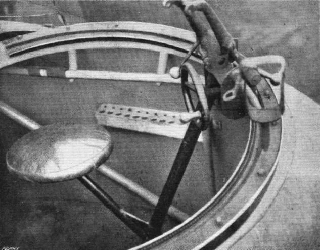
C. Front cockpit and gun mount.

L. Gun mounting in rear cockpit.
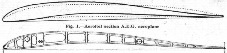
Fig. 1. - Aerofoil section A.E.G. aeroplane.
Fig. 2.
Fig. 2.

Fig. 3. Fig. 4. Fig. 5.

Fig. 6. Fig. 7. Fig. 8. Fig. 9.
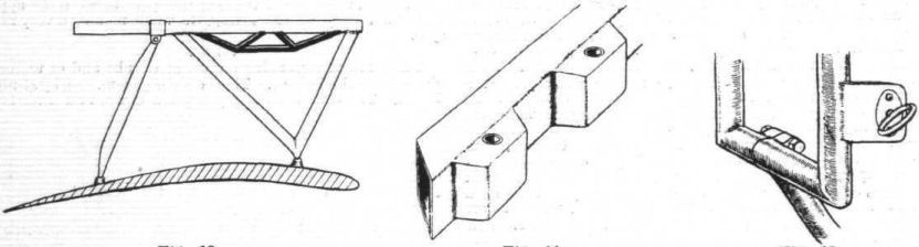
Fig. 10. Fig. 11. Fig. 12.

Fig. 13. Fig. 14. Fig. 15.
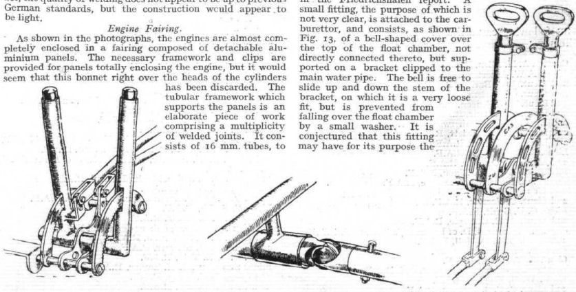
Fig. 16. Fig. 17. Fig. 18.

Fig. 19.
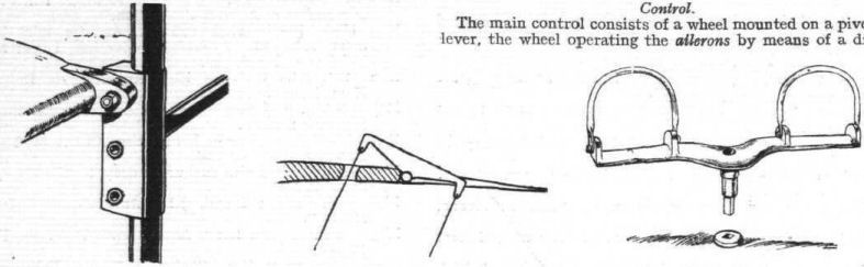
Fig. 20. Fig. 21. Fig. 22.
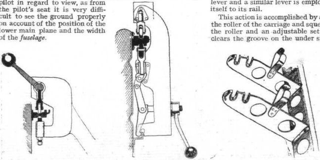
Fig. 23. Fig. 24. Fig. 25.

Fig. 26. Fig. 27.
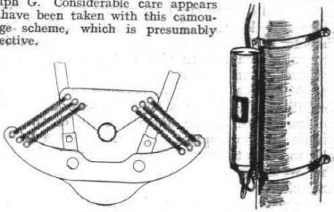
Fig. 28. Fig. 29.
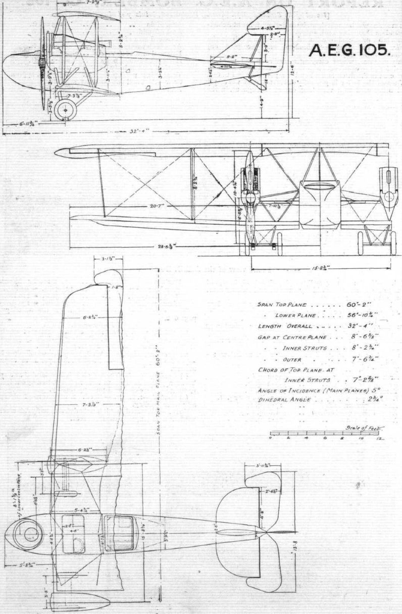
Flight, August 29, 1918.
THE A.E.G, ARMOURED AEROPLANE.
Issued by the Technical Department (Aircraft Production) Ministry of Munitions.
THIS machine was brought down by an R.E.8 of 21st Squadron, near Hinges, on May 16th, 1918. It bears the date February 3rd, 1918, stamped on the main planes, and also on portions of the fuselage, and is the first of its type to have been secured.
This aeroplane is designed for the purpose of carrying out offensive patrols against infantry, and is furnished with armour, which affords protection for its personnel. This armour appears, however, to be more or less experimental. In general construction it closely follows the lines of the A.E.G. twin-engined bomber G. 105, reported on in I.C. 607, though the arrangement of the power plant is, of course, entirely different. A steel tubular construction is used practically throughout. The machine was badly crashed, and some details are, therefore, not available ; but the general arrangement drawings at the end of this report may be regarded as substantially accurate.
The leading particulars of the machine are as follows :- Area of upper wings, 190.4 sq. ft.; area of lower wings, 168 sq. ft.; total area of wings, 358.4 sq. ft.; area of upper aileron, 11.2 sq. ft. ; area of lower aileron, 10 sq. ft.; area of tail plane, 9.4 sq. ft.; area of fin, 7.6 sq. ft.; area of rudder, 6 sq. ft.; horizontal area of body, 48. 6 sq. ft.; side area of body, 54.8 sq. ft.; cross sectional area of body, 14.4 sq. ft.; area of side armour, 33 sq. ft.; area of bottom armour, 29.4 sq. ft.; area of armour bulkhead, 10.4 sq. ft.
Engine, 200 h.p. "Benz." Crew - pilot and gunner, 360 lbs.; armament - three guns; petrol capacity, 38 galls.; oil capacity, 3 galls. The principal dimensions are shown on the general arrangements drawings.
Wings.
The manner in which the wings are constructed is exactly as shown in the report of the A.E.G. bomber - i.e., the spars consist of two steel tubes 40 mm. in diameter by .75 mm. thick. At their ends the upper and lower surfaces of the spars are chamfered away, and flat plates welded in position, so as to provide a taper within the washed-out portion of the wing tips. The wings were, unfortunately, so badly damaged that no accurate drawing of their section can be taken, but there is evidence that this very closely follows the section of the bomber, which has already been published. The ribs are of wood, and between each main rib is placed a half-rib joining the front spar to the semicircular section wooden strip which forms the leading edge. The wing construction is strengthened by two light steel tubes passing through the ribs close behind and parallel to the leading spar, which are used for housing the aileron control wires. The bracing against drag consists of wires and transverse steel tubes welded in position. At the inner end of the wings special reinforced ribs of light gauge steel tube are provided. The method of construction at this point is clearly shown in Fig. 1, which also indicates the manner in which the bracing tube is welded to a socket driven on the main spar. The spars are attached to the fuselage by plain pin joints.
Centre Section.
The centre section of the upper surface is constructed in a similar manner to that of the wings, except that it is considerably reinforced, and the spars are larger in diameter. The leading spar has a diameter of 51 mm. and the rear spar 45 mm. The centre section is secured to the fuselage by a system of stream-lined steel struts, the feet of which terminate in ball-ends dropped into sockets, and there bolted in position. One of these struts is shown in Fig. 2. The centre section contains an auxiliary gravity petrol tank, and also the radiator, and is, therefore, substantially braced with steel tube transverse members. The wings are set with a dihedral angle of approximately 6 deg.
Ailerons.
The aileron framework is of light steel tube throughout, the tube forming the trailing edge being flattened into an elliptical section. The ribs are fixed by welding. The framework of the ailerons on the upper wing is reinforced by diagonal bracing of light tube.
Struts.
These are of light steel tube stream-line in section, tapered at each end, and terminating in a socket which abuts against a ball-headed pedestal carried on the wing spars; through the socket and the ball is passed a small bolt. The manner in which this attachment is carried out is exactly similar to that described in I.C. 607.
Fuselage.
The whole of the fuselage is built up of steel tubes welded together, and having affixed at their junctions sheet steel lugs, which serve as the anchorage for the bracing wires. The diameter of the longerons and of the frame verticals is 20 mm., except the last three members adjacent to the tail, of which the diameter is 16 mm. The welding throughout the fuselage appears to be of very high quality. In Fig. 2 is illustrated a joint, which occurs in the fuselage immediately in front of the pilot's cockpit. The longeron is, from this point to the rear of the gunner's cockpit, fitted with a wooden strip taped in position. This joint shows the method in which the cross bracing wires are furnished with an anchorage. In one or two points in the frame construction the bracing wire lies in the same plane as the transverse tube, and to allow for this a diagonal hole is drilled through the tube and filled in with a small steel tube welded in place.
Engine Mounting.
This consists of a triangulated arrangement of steel tubes carrying hollow rectangular section steel bearers, on which the crank chamber is slung. The bearers are well trussed both in the vertical and horizontal planes, and are shown in dotted lines in the general arrangement drawings. The engine bearers themselves are 2 mm. in thickness, and have an approximate section of 2 1/16 ins. by 1 1/2 ins.
Tail.
The empennage possesses no particular points of interest, the planes having the usual steel tubular framework. The tail plane is not fitted with any trimming gear, but a method of adjustment is provided. This is shown in Fig. 3, which is self-explanatory. The diagonal struts which proceed from the base of the fuselage to the tail plane spar are fitted at each end with a method of adjustment shown in Fig. 4, allowing them to be extended as required according to the particular socket which is used to carry the leading edge of the tail plane. Neither the elevators nor the rudder are balanced. The rudder post is mounted on the end of the fuselage, as shown in Fig. 5, in which it will be seen that the vertical frame tube of the fin is very stoutly attached to the frame by a triangulated foot.
Landing Gear.
This is of the usual A.E.G. type, and is furnished with shock absorbers consisting of metal coil springs in direct tension, as is clearly shown in the general arrangement drawing.
The landing carriage axle has a diameter of 55 mm. The landing carriage struts, which are of similar section to those used between the planes, measure 70 mm. by 37 mm. At their upper ends they are furnished with ball and socket attachments similar to those of the interplane struts.
The wheels are fitted with 810 by 125 mm. tyres, and the track is 6 ft. 10 1/2 in.
The tail skid is unusually heavy, and it is a built-up construction of welded sheet steel. It is mounted on a stout tail post, which is reinforced by four stream-line steel diagonals. The forward end of the tail skid projects inside the fuselage and is there provided with four steel springs in direct tension. A sketch of the tail skid is given in Fig. 6.
Control.
This consists of the usual double-handled lever mounted on a transverse rocking shaft, which carries the elevator control cranks at each end. The upper ailerons are worked positively by wires which pass over pulleys on the wing spars at the outer struts, the outer and lower ailerons being connected by a stream-line steel tubular strut.
Engine.
The 200 h.p. Benz engine possesses no new features, and has already been made the subject of an exhaustive report.
Petrol System.
Underneath the pilot's seat are the two main petrol tanks, each of which contains 80 litres (equal to 16 gallons). These tanks are of brass, and are fitted with Maximall level indicators. The gravity tank, containing 27 litres (equals 5 1/2 gallons) is embedded in the centre section of the upper plane, where it forms the leading edge on the left-hand side. This tank is made of lead-covered steel. Cocks are provided, so that either the gravity tank or the pressure tanks, separately or together, can feed the carburettor.
It is of interest to note that the chamber which is used in connection with the Benz petrol supply system is not, as is usually the case, contained in the main tank, but is a separate fitting mounted on the side of the engine.
Radiator.
The radiator is of the Daimler-Mercedes type, measuring 32 1/2 ins. long by 11 1/2 ins. high and 6 ins. deep. This is fitted with imitation honeycomb tubes, of which there are 118 running vertically, each being fitted with 48 gills. The radiator is carried in a steel cradle, into which it is easily inserted from above, and this in turn is supported on specially built-up steel ribs. It is placed so that the tank which forms the upper part of the radiator lies about flush with the centre section of the top plane. The shutter or flap for controlling the water temperature is made of 3-ply wood stiffened with a light steel framework, and is mounted immediately behind the radiator, being worked by a handle within reach of the pilot. This handle is provided with a rack and pawl device. The shutter is 3 3/4 ins. deep, and is capable, therefore, of covering up about one-third of the total radiator surface. It will be noted that the position of the shutter behind the radiator is unusual.
Armour.
Protection for the pilot and gunner is afforded by armour, which, is shown in the general arrangement drawing in thick lines. There are three panels at each side, and three panels at the bottom of the fuselage, an armour bulkhead being placed at the rear of the gunner's cockpit to protect him from behind. The armour is 5.1 mm. thick, and its total area is 105.8 sq. ft. The weight of the armour is thus approximately 860 lbs. Careful tests have been made to ascertain the effectiveness of this armour, and the following table gives the ranges at which these plates are safe or unsafe against penetration by bullets of various types. These figures may be taken as correct within the limit of a practical firing test.
Angle to Normal Safe range Unsafe range
Ammunition. degrees. yards. yards.
German A.P. 0 - 600
15 500 400
30 400 300
Mark VII. 0 probably 700 600
Armour 15 400 300
piercing 30 300 200
German Spitze 0 150 100
15 100 50
30 50
Mark VII. 0 50
15 50
30 50
The armour is undoubtedly too light to afford protection against British armour-piercing bullets fired from the ground at a lower height than 500 ft., while a machine armoured with it would have to fly at, at least, 1,000 ft. to be safe from all but a very low percentage of hits.
The armour does not appear to have been employed, as it might well have been, in a structural capacity - i.e., it is simply an attachment to the framework, to which it adds no material strength. Its appearance seems to point to the fact that it had been added by way of experiment, and that it was of a more or less makeshift character. It had, for instance, evidently been necessary to open out existing holes and cut new holes in the course of erection. The armour is attached by set screws to clips clamped on the fuselage members, as shown in Fig. 7.
Armament.
In this machine the pilot is not provided with a gun, but the observer has to control three, of which two (Spandau) are fixed on the flooring of his cockpit, whilst the other (Parabellum) is carried on a rotatable mounting.
With regard to the fixed guns, these are secured to a couple of tubular steel brackets, mounted as shown in Fig. 8. The oval-section steel tubes, of which these brackets are composed, are welded to a light steel base, which forms a sort of tray, and is in turn bolted to the panel of armour which forms the floor of the cockpit.
Adjacent to these two guns, which fire forward at an angle of 45 deg., is a bracket carrying the belts of ammunition, which are fed from a large rotating drum.
In the right-hand front corner of the pilot's cockpit floor is a circular hole, which he would appear to use for sight purposes. The fixed guns are controlled by Bowden wires and triggers mounted on a diagonal frame member, convenient to the gunner's right hand, as shown in Fig. 9. The movable gun is of the Parabellum type, and the mounting is of the usual built-up wood variety. The gun cradle is, however, novel, the fixture for this purpose being illustrated in Fig. 10. It appears to be rather more handy than the usual German device, but is by no means lacking in weight. This fitting was in a very badly smashed condition. The vertical carrier is swivelled at its base, and is secured in position by sliding bolts engaging with teeth cut in the turned-up base plate. These sliding bolts are worked by a direct acting thumb lever. The turn-table is made of a single hoop of wood reinforced at the point where the gun is mounted by glued-on strips of ply-wood. A locking device of the type shown in Fig. 11 is fitted.
The transverse bracing in the immediate rear of the gunner's cockpit, at which point is mounted the armour bulkhead, suggests that it was the original intention for this aeroplane to carry a gun or guns firing downwards and backwards through a hole in the fuselage. The transverse arrangement of steel tubes and bracing wires is shown in Fig. 12.
Wireless and Heating.
The machine is fitted with the usual wireless leads and apparatus for heating, the dynamo being carried on a bracket attached to the fuselage immediately in front of the pilot's seat, where it is directly driven from the engine through a hand-controlled clutch. No wireless fittings, other than the dynamo and the leads, were found on the machine.
Instruments.
The instruments fitted to this machine are of standard type, and possess no new features of interest.
Fabric and Dope.
The fabric throughout is of good quality, but the dope appears to have been badly applied, as in many points it had completely peeled off the fabric.
Camouflage.
The colours used are dark purple and dark green, and in contradistinction to the usual method by which they are arranged in well-defined polygons, are applied so as to give a cloudy effect, and appear to have been sprayed on.
Steel Analysis.
A sample of the wing spar yields the following analysis :-
Carbon .098 per cent. Phosphor .014 per cent.
Silicon .011 per cent. Manganese .461 per cent.
Sulphur .017 per cent. Chromium .036 per cent.
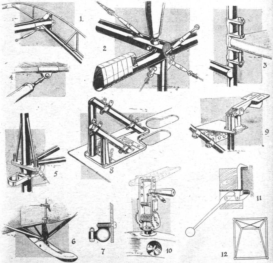
1. Wing-Spar Butt and intermast Ribs of the A.E.G. 2. Centre-Section Strut and Fuselage Junction of the A.E.G. 3. Tail-plane Adjustments. 4. Tail-stay Adjustments. 5. Rudder-post Arrangements. 6. Tail-skid Arrangement. 7. Method of Attaching Armour. 8. Method of fixing guns to fire through floor. 9. Triggers for fixed guns. 10. Cradle for Movable Gun. 11. Locking device for Movable Gun. 12. Method of Fuselage Bracing.
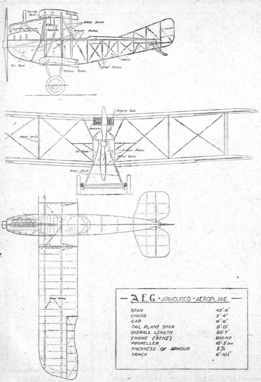
The A.E.G. armoured aeroplane.
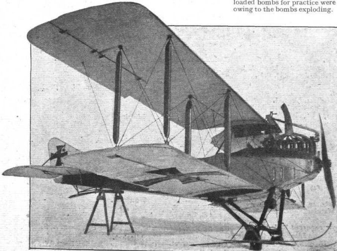
For Winter Wear only. - A German biplane fitted with skids instead of wheels for starting from and landing on the snow.
Flight, February 28, 1918.
AN ALBATROS FIGHTING BIPLANE.
[Some time ago (in our issue of December 13th, 1917, to be exact) we published scale drawings and particulars of a captured German (Ago) biplane. Since then we have been, by the courtesy of the authorities, accorded every facility for obtaining full particulars of other captured German machines, and as a result we commence this week a detailed description of a very interesting enemy Albatros biplane, which has been captured practically intact. We are dealing with this machine rather more thoroughly than has usually been possible for us to do in the case of the majority of our descriptions of aeroplanes. This is partly because the machine is a very interesting one, and partly to aid those who, although the view-rooms in which these machines are exhibited are open to them at the request of their firms, live too far away, or for other reasons are unable to avail themselves of this opportunity of studying in detail modern German methods of aeroplane construction. The visitors' book at the view rooms in question reveals the fact that representatives and employees of numerous aircraft firms have taken the opportunity of paying a visit to this interesting exhibition, but it also shows that many firms, chiefly those situated far from London, are not yet to be found among the visitors. To those we therefore hope our descriptive articles will form an acceptable substitute for an examination of the actual machine. Further, among our American, French, and Italian Allies there will probably be many who would be interested in the details of a modern German aeroplane, and we therefore hope that aviation journals in these countries will consider themselves at liberty to reprint these articles. Our only stipulation is that when reprinting "FLIGHT" should be acknowledged. - ED.]
THE Albatros biplane on view at the enemy aircraft view-rooms belongs to what is now commonly referred to as the C class, that is to say, a general utility machine used for artillery observation, reconnaissance work, photography, and fighting. Incidentally the machine appears to be also used for bombing - in a small way only - as it is equipped with a bomb rack holding four bombs.
Aerodynamically the Albatros to be dealt with in what follows is, perhaps, chiefly interesting on account of the evident attempt on the part of the designer to provide as good a stream-line body as is possible having regard to such external fitments as machine guns, &c, which naturally detract to a certain extent from the efficiency of the lines of a body of a modern two-seater, where the gunner frequently has to stand up, with the upper portion of his body projecting above the fuselage covering. This effort at stream-lining is particularly noticeable in the nose of the machine, where the aluminium cowling over the engine is carried right across, leaving only the exhaust collector exposed. In front of the covering of the body proper is a cowl shaped as a truncated cone, which serves to enclose the nose and reduction gear of the engine, and to carry the lines of the body into those of the "spinner" around the boss of the air screw. The sides of the body, from a short distance behind this cowl to the tail, are flat, as is also the bottom, but the top of the fuselage is covered with a curved covering of three-ply.
At the rear the fuselage terminates in a horizontal knife's edge, an easy flow being provided for the air by running the top covering of the fuselage into the three-ply covering of the fin in a smooth curve. Similarly, the fixed tail plane, which is of a symmetrical section and very deep, has its top surface practically in continuation of the top covering of the body, presenting no great and abrupt changes in curvature. The total effect is one of extremely smooth and easy flowing curves, and the body resistance cannot be very great in proportion to the cross sectional area of the body. We have no figures of the actual resistance coefficient in the formula R = k AV^2, but are inclined to imagine that the coefficient k has quite a low value.
As regards the rest of the machine, the Albatros designer does not appear to have been so careful in cutting down resistance. For instance, the wings have the usual circular section stranded cables for taking lift and landing stresses, and no attempt appears to have been made at stream-lining these.
Constructionally the Albatros shows much that is of interest, chiefly in the construction of the body, but also in other respects, as we hope to show in later instalments of this descriptive article. Fundamentally, the Albatros body construction is that employed in building light boats and hydroplanes. There is a light framework, consisting of four main rails at the corners of the rectangular section body, two auxiliary rails somewhere about half-way up on the sides, and bulkheads or transverse partitions of varying shape and thickness along the body at intervals. The whole is then, as in boat building, covered with a skin of ply-wood, in this case three-ply. Regarded as a compromise this form of body construction would appear to be quite good. Without entailing the time and expense of the true monocoque body, it provides a reasonably good stream-line form. As a manufacturing proposition it is probably about equal to the girder type of fuselage, while it has the advantage of not requiring any trueing up in the erecting process, this following automatically when making the parts over jigs and formers. One advantage this form of body does appear to possess, although to a somewhat lesser extent than the true monocoque - shell splinters and rifle and machine gun bullets are less likely to damage it seriously than is the case with the girder type. In the latter, should a longeron be shot through nearly all the strength of the structure is gone, whereas this semi-monocoque structure would retain its strength even after damaging some of the longitudinal members.
Finally, there is the question of strength for weight. We have no data relating to tests of such a structure carried out by our own authorities, although possibly such tests may have been, and certainly should be, made. But in our issue of April 4th, 1914, we published particulars of an Albatros biplane which was brought over to this country and flown here by Thelen, which had a body fundamentally similar to the one at present under discussion, although differing from it in minor details. At the time we were furnished with some particulars of tests carried out on an Albatros fuselage of this type by the Deutsche Versuchsanstalt fur Luftfahrt, according to which the factor of safety of the Albatros body was about 60, and the resistance to bending 2.5 times greater than that of a diagonally wired fuselage of the same outside dimensions, and having members of the size usually employed in structures of this type. The Versuchsanstalt also stated that the Albatros firm were justified in concluding that the bending resistance of the veneer type of body is greater than that of a cross wired fuselage of the same weight, although no actual figures were given showing how much greater.
When looking into the detail construction of the Albatros body, the first thing that impresses one, apart from the absence of internal cross bracing, is the extensive use that has been made of ply-wood in the construction of the transverse bulkheads or formers, which take the place of the struts and cross members of the girder type of body. In Fig. 1 are shown the different bulkheads of the body, with dimensions, &c. The rail half-way up the sides of the body is placed parallel with the propeller shaft, thus serving as a datum line from which to make measurements of distances and angles.
In order to enable our readers to better form a conception of the Albatros construction we have shown, in Fig. 1, half-sections of the more important and representative bulkheads. In the front portion of the body the bulkheads, which here have to take the weight of the engine, are about 1 1/4 in. thick, and are made up of a number of laminations of wood, which are, of course, so placed in relation to one another that the grains of adjacent layers run at angles to one another. It was further noticed that in making up these bulkheads whole sheets of the different woods were not always employed. On the contrary, many of the layers appear to have been shouldered or spliced, being made up of comparatively small pieces. It is possible that this has been done with a view to utilising pieces of wood that would otherwise have had to be scrapped. On the other hand it may have been done to increase the amount of crossing of the different grains. In any case, it would appear to serve both purposes, although one would expect the time taken in manufacture to be somewhat increased by such careful fitting together of small pieces of wood.
Fig. 2 shows the nose of the Albatros, and clearly indicates the method of supporting the engine. The first bulkhead, it will be seen, is solid, and is at right angles to the propeller shaft. The second bulkhead - 2, Fig. 1 - is lightened by piercing as shown, and is also vertical, while the third engine support is formed by a solid bulkhead - 3, Fig. 1 - which slopes back so as to support the front chassis struts and front cabane struts at its lower and upper ends respectively. As the front engine support is clearly shown in the sketch, Fig. 2, it has not been included in Fig. 1. The bulkhead numbered 1 in Fig. 1 is merely a former, and does not help to support the engine bearers. These are of I section spruce, and have plywood flanges top and bottom as shown in Fig. 3. The upper flange is continued outwards to the middle longeron so as to form a shelf or bracket at the sides of the engine.
A construction somewhat different to that of the engine supports is employed in the panel between the pilot's and gunner's cockpits. This consists (4. Fig. 1) of a spruce framework faced each side with 3 mm. three-ply, the whole having a thickness of 26 mm. (about 1 in.). Behind the gunner's cockpit is a light partition built up as shown in 5, Fig. 1. Two light spruce struts run diagonally across from corner to corner of the body, crossing in the centre of the fuselage at which point they are reinforced by three-ply facings and triangular blocks glued into the corners.
Their attachment to the upper and lower body longerons is of a similar construction, and will be clear from the diagram. On their front faces these diagonal struts are provided with a 2 mm. flange to stiffen them against buckling. A canvas curtain is secured to the front of this partition, having in it pockets for maps, &c.
From this point back to the point where the tail plane and vertical fin are attached, the formers of the body are in the nature of a very light framework of thin struts, a typical one being shown in 6, Fig. 1. The general construction and some of the dimensions of the various members will be clear from the illustration.
One of the features in which the present Albatros differs from previous types is the construction and attachment of the tail plane and vertical fin. The latter is covered with three-ply, and is made integral with the body, out of which it grows, so to speak. The construction is shown in 7 and 8, Fig. 1, and in the perspective sketch, Fig. 4. The tail skid is supported on one and sprung from the other of these two bulkheads, as illustrated in Fig. 5, the general and detail construction of it being evident from the sketches. The tail plane is provided with hollow spars which fit over cantilever beams integral with bulkheads, 7 and 8, Fig. 1, the details of which arrangement will be dealt with later.
(To be continued.)
Flight, March 7, 1918.
AN ALBATROS FIGHTING BIPLANE.
(Continued from page 227.)
HAVING dealt with the bulkheads or transverse partitions of the Albatros fuselage in our issue of last week, the longitudinal rails will be considered next. These are of a somewhat complicated nature, varying as they do along their entire length, not only as regards being tapered from front to rear, but also in the different form of spindling out employed at the various points, and in the method of reinforcing with other strips of wood, partly in order to increase their strength where required and partly to make their overall section conform to the various angles and curvatures of the outside three-ply covering of the fuselage.
From Fig. 6 a fairly good idea may be formed of the shape and dimensions of the longerons at various points. The lower one (left hand) is originally of rectangular section, but is lightened from point to point by various forms of spindling and stop-chamfering. Thus at the point B (see key, diagram Fig. 6), the inner face of the bottom longeron is spindled out on its inner face with a curved cutter. At other points of this longeron farther towards the stern various sections are met with, as channel, solid rectangle, and L sections of various proportions. Between the horizontal stern post and the point at which the middle longeron meets the lower one, the latter is reinforced with a triangular section strip, so as to carry the three-ply covering into the sloping side. Similarly at the section A, Fig. 6. the longeron, which is here of solid rectangular section, is reinforced on the outer side with a curved trip, spindled out externally, and with a smaller strip on the lower face of the longeron. This is done partly to strengthen the longeron, which at this point is subject to an increased compressive load, owing to the overhung engine, and also to afford attachment for the three-ply covering, which at this point changes from flat sided to rounded section where the sides gradually merge into the truncated cone of aluminium which forms the extreme nose of the body proper, i.e., at the point just behind the "spinner" on the air screw boss.
The upper longeron, which is originally of rectangular section, is spindled out to channel and L sections at various points, as shown in X, Y, Z, Fig. 6. So as to form an attachment for the curved top of the body, the top longerons have glued to their upper face additional strips of triangular section while at the point Y, Fig. 6., the section is left rectangular so as to form a support for the gun ring. In addition to their function as strengthening members these strips serve the further purpose of preventing the bulkheads from sliding along the longerons, as they are cut off where a bulkhead occurs, against the front and rear sides of which they abut. In some places, as for instance in the front of the body where the covering is in the form of an aluminium cowl over the engine, the strips are omitted and the cowl attached to turnbuttons as shown in the sketch Fig. 7. At such points the bulkheads are prevented from sliding along the longerons by a long wood screw passing horizontally through the longeron into the bulkhead.
The middle longerons, which, as already pointed out in a previous article, are horizontal, i.e., parallel to the propeller shaft, are of smaller overall dimensions than are the four main longerons. They are rectangular section, lightened in places by stop-chamfering, as shown in a and b Fig. 6.
Fig. 8 shows, in side elevation and plan, the general arrangement of the fuselage, and should, in conjunction with the various sections and key diagrams, explain fairly clearly the general lay-out of the body. It will be noticed that in plan the sides of the body are straight from the tail post forward to the pilot's cockpit. For ease in manufacture it is an advantage that the ribs of the tail plane should be at right angles to the spars, and in order to effect this it is necessary that the sides of the body should be parallel for the length of the tail plane. Since, however, to provide for this the longerons would have to be changed from a converging direction to a parallel one which would necessitate a somewhat sharp bend in them at the point where the tail plane commences, and as, moreover, the depth of the tail plane is not the same as that of the body except at the extreme rear, a different course has been followed. From the point where the tail begins two extra longerons on each side have been built into the bulkheads of the body. These two short longerons have, in plan, a direction parallel to the line of flight, while the main longerons continue on their converging course. This arrangement is indicated in the plan view Fig. 8. In side elevation the short longerons, against which lie the inner ribs of the tail plane, have the same curvature as the tail plane. In this manner the lines of the rear part of the body are not spoiled, while an easy flowing curve is provided for running the tail plane into the body. The arrangement will be further made clear by reference to Fig. 1, page 224.
Reference has already been made to the peculiar attachment of the tail plane to the body. The sketch at the top of Fig. 9 shows in perspective this attachment, which is also illustrated in the diagram in the bottom left-hand corner of Fig. 9. The bulkheads of the body are extended outwards to form cantilever beams which support the tail plane. There are three of these cantilever beams, while further support is provided for the tail plane leading and trailing edges as indicated in the sketches. The spars of the tail plane are of the box type, built up of ash flanges with thin three-ply sides, cut out for lightness. These spars are so proportioned that they lit over the cantilever beams, which do not, it will be seen, run right out to the edge of the tail plane, but are finished off just outside the second tail plane rib. No external bracing of the tail plane is provided, the depth of it and the method of mounting being relied on for the necessary strength.
To provide against the tail plane sliding off its cantilever supports it is secured at the leading and trailing edge. The former attachment is indicated in the bottom right-hand corner of Fig. 9. A sheet steel shoe fits over the corner of the leading edge and inner rib, and through this shoe a long bolt passes, which runs across the body to a similar shoe on the other side. In Fig. 10 is shown the rear attachment of the tail plane. A sheet steel box surrounds the corner of the fuselage. Welded to this box is a short tube which fits into a circular recess in the end of the trailing edge of the tail plane. As the elevator tube runs right across and is fitted with collars bearing against the sides of the clips that form the bearing for the elevator tube, the trailing edge of the tail plane is prevented from slipping outwards.
The manner employed of forming bearings for the elevator is indicated in the diagrams of Fig. 10. A steel strip is bent over the tube, and its two free ends are bent over and fit into slots in the trailing edge of the tail plane. Each clip is then secured to the tail plane by a vertical bolt as shown in the diagram. The trailing edge of the tail plane is spindled out to a semi-circular section as shown, and a curved metal distance piece is screwed to this trailing edge or spar, so as to form the second half of the bearing of which the bent steel strip forms the other half. To remove the elevator the bolts securing the clips are undone; the clips are then bent outwards until their free ends clear the slots, when the elevator can be removed bodily.
As the elevator is built of steel tubing throughout, wood blocks of the shape shown in detail 1, Fig. 10, are employed for attaching the fabric covering. These blocks span over the steel strip bearings, and are secured to the tubular leading edge of the elevator by screws as shown in section B-B. A hole in the opposite wall of the tube serves for the insertion of the screwdriver.
Under the horizontal stern post of the body are two short tube stumps, closed at their lower ends. The object of these is not at first apparent, since they appear too short to protect the elevator, but when it is remembered that the Germans favour transportation by road, trailing the aeroplane behind a lorry, it becomes at once evident that these stumps serve to support the stern of the body on the floor of a lorry while the machine is trailed behind on its own wheels.
As regards the remaining details of the tail of the Albatros little need be said, as they are fairly evident from the plan and sections of Fig. 11. It will suffice to point out a rather ingenious construction of the leading edge of the tail plane. In plan the tail plane, it will be seen, is roughly semi-circular, and its leading edge therefore has to be shaped to this curvature. As an ordinary strip of solid spruce spindled out to a semi-circular section would scarcely be strong enough for this work a different method has been employed. It appears that originally the leading edge of the tail is made up of four laminations of ash, having, of course their grains running in slightly different directions. The rectangular section spar thus formed is then spindled out to a semi-circular section, as shown in the diagram, leaving the impression that the leading edge is made up of seven thin strips of wood glued together. The resulting leading edge appears to be one of great strength, while at the same time being quite light.
(To be continued.)
Flight, March 14, 1918.
AN ALBATROS FIGHTING BIPLANE.
(Continued from page 255.)
THE cockpits of the Albatros are arranged in the fashion now universally adopted for two seaters, by Allies as well as by the enemy, i.e., the pilot in front and the gunner in the rear cockpit. The pilot's seat is mounted, in the Albatros, on the main petrol tank, which has two annexes on top, one on each side of the seat. This arrangement is clearly indicated in Fig 12, in which the small clips preventing the seat from sliding about on the tank will be noticed. The filler cap is mounted on a tubular projection extending through the fuselage covering, thus enabling the tank to be refilled from the outside. A smaller auxiliary tank is mounted above and to the rear of the main tank, in the gunner's cockpit, as a matter of fact. Both tanks are connected up to a by-pass or distributor, so that both or either tank can be connected up to the engine, two pumps being provided for maintaining the necessary pressure, one driven by the engine and the other hand operated. Thus, whatever tank is being used, petrol is fed to the carburetor under pressure. This has probably been a necessary provision, as the tanks are placed relatively low and gravity feed would, therefore, be apt to be unreliable when the machine is climbing at a fairly steep angle.
Constructionally the petrol tanks are of interest in that they have been internally braced by rods running across from side to side, the attachment of the rods being visible on the outside of the tank as shown in Fig. 12 (p. 285). To prevent the petrol from slushing about inside when the tank is nearly empty baffle plates are fitted dividing the man tank longitudinally into five compartments, communicating with each other through the circular open rigs shown in the section of the tank. Fig. 12. As the supply pipe leaves the tank fairly high up - it can be seen on the front right-hand side of the tank in Fig. 12 - it is carried down inside to the bottom of the tank so as to enable the last drop of petrol to be forced out and into the carburettor. The main tank is mounted on brackets as shown in one of our sketches, and is secured by metal straps having an arrangement for adjustment.
In Fig. 13 (p. 285) is shown the general arrangement of the controls. There is a transverse rocking shaft on which are mounted at each end crank levers for operating the elevators, while in the centre, pivoted so as to be free to rock laterally, is mounted the main control lever. Mounted on the transverse shaft, but not moving with it, is another lever, which operates the claw brake mounted on the wheel axle. The arrangement of this brake is shown in Fig. 14. By pulling the lever the free end of the claw brake is pulled upwards, thus causing the claw to dig into the ground. On releasing the lever, the brake is returned to its normal position by the action of the spring shown in the sketch.
The transverse rocking shaft is carried, as indicated in Fig. 14, in two bearings mounted on the lower longerons. A forward and backward movement of the control lever causes the shaft to oscillate, and with it the two crank levers to which are attached the elevator control cables. These cables run from the crank lever, around a pulley slightly forward of the transverse shaft as shown in the sketch, and hence to the top crank lever on the elevator. The return cable runs from the crank on the under side of the elevator to the crank on the transverse shaft. En route these cables pass over pulleys mounted in the rear position of the fuselage, these pulleys being shown in detail in some of the accompanying sketches (Fig. 15).
(To be continued.)
Flight, March 21, 1918.
AN ALBATROS FIGHTING BIPLANE.
(Continued from page 287.)
As regards lateral control, the general arrangement of this is indicated in diagrammatic form in Fig. 16. From the control lever the direct cable passes over a pulley on the transverse shaft, along through the bottom wing, around another pulley in the wing, and hence to the rear half of the aileron crank lever. The return cable runs from the front half of the aileron crank lever, around another pulley in the lower wing, through the wing and through the transverse shaft to a pulley on the other side of the control lever, and hence to the screw on the control fever. The details will be clear from Fig. 13.
The foot bar operating the rudder is mounted on a pyramid of steel tubes, and the rudder cables are taken, not, it will be seen, from the foot bar itself as is generally done, but from a short lever projecting forward at right angles to the foot bar. From this lever the cables pass over pulleys and to the cranks on the rudder. It will be seen that provision has been made for making adjustments of the foot bar to suit pilots of different height by fitting an extra foot bar. If the machine is to be flown by a taller pilot, this is removed and the main foot bar used. Wire clips are provided, it will be noticed, for accommodating the pilot's heels so as to prevent his feet from slipping off the foot bar.
As in the majority of German machines provision has been made for locking the control lever in any position, either flying level, climbing, or descending. This is accomplished by means of a collar free to slide along the control column, but being split and provided with a bolt for tightening up, when the collar is locked in position on the control column. Anchored to this collar by two screws is a fork end, from which a tube runs down and forward to terminate in a ball and socket joint secured to the bottom of the fuselage. This ball and socket joint, it will be seen, enables the control column to be moved freely in any direction, and to allow it to be moved from side to side, even when the forward movement of the column is prevented, by locking the collar. In this manner, the pilot can lock the elevator, while operating the control column from side to side for lateral control with his knees.
As far as can be ascertained, although the machine gun was not in place on the machine as exhibited, one synchronised machine gun was fitted, resting on top of the fuselage on the right-hand side. The pilot operated this gun by means of the trigger on the hand grip of his control lever, which is shown inset in Fig. 13.
While on the subject of controls, reference might be made to the crank levers on the elevator and rudder. These are shown in Fig. 17, from which their construction will be evident. The crank lever of the elevator has projecting from it a tapering tube running to the trailing edge of the elevator. The tubular rudder post is working in bearings similar to those described in our last issue when dealing with the hinges for the elevator. At the bottom the rudder tube fits into and is supported by a socket carried on a clip bolted to one of the transverse bulkheads of the fuselage. A peculiarity characteristic of the Albatros is the method of attaching the control cables to the crank levers. A socket is formed in the end of the crank lever, and into this fits a cup-shaped piece of steel machined on one of the bolts of the wire strainers, much in the same manner as the terminal attachment of the main lift cables. Thus any vibration in the control cable is not transmitted to the crank lever, the cup-shaped head of the turnbuckle bolt being free to move in its socket in the crank lever.
Reference has already been made to one part of the armament of the Albatros, namely, the synchronized machine gun operated by the pilot from the trigger on the main control column. In addition there is a movable machine gun mounted on the usual gun ring in the rear cockpit. The general arrangement of this gun mounting is shown in the sketch, Fig. 18. The gun ring itself is built up of thin three-ply wood, and runs on small rollers on its support so as to reduce friction. It is prevented from tilting up by wooden angle pieces screwed to its underside and overlapping the fixed support. The whole arrangement looks somewhat clumsy, but is apparently quite light, and the strength is probably reasonably good, as the three-ply of which the gun ring is made up of different curvatures, each of which tends to strengthen the others.
The machine gun is supported on the gun ring by a swivelling fork, which can be raised and lowered as required, and which, can be locked in any desired position by the locking arrangement indicated in the sketch of the general arrangement. In addition to .its circular movement integrally with the gun ring, the machine gun may be swung laterally on its pivot in the gun ring. Here also a locking device is provided in the shape of a split collar locked by an L bolt, as shown in one of the insets. The other inset in Fig. 18 shows the lever by means of which the gun ring is locked in any desired position. A rocker arm composed of two steel strips is pivoted in its centre on a pillar projecting downwards from the gun ring. At one end this rocker arm carries a plate welded to the two steel strips of the rocker, and at the other it carries the hand lever which is so formed and pivoted as to give an eccentric movement when the lever is swung through an arc. The modus operandi will be clear from the sketch. When the gun ring has been swung around to the desired position, the hand lever is pushed down; in so doing the eccentric forces the inner end of the rocker down, thus causing its outer end carrying the flat plate to move up against the fixed support for the gun ring and thereby locking it. A pull on the lever instantly releases the gun ring if it is desired to swing the gun around to another quarter.
As presumably it frequently happens that the gunner wishes to fire from a standing position his seat has been so arranged as to swing into a vertical position as soon as it is relieved of his weight. This is accomplished by means of a spring under the seat, as shown in Fig. 19, which is, we think, self-explanatory. A strip of wood runs transversely under the seat and projects a short distance on either side. These projections rest, when the seat is in a horizontal position, in brackets secured to the sides of the fuselage.
(To be continued.)
Flight, March 28, 1918.
AN ALBATROS FIGHTING BIPLANE.
(Continued from page 310.)
THE Albatros biplane belongs to the C class, that is to say is a general utility machine variously used for fighting, reconnaissance, artillery spotting and photography, and is therefore not to be considered a bombing machine. It is, however, provided with racks for a small number of bombs - four, to be exact - presumably by way of cases of emergency when a suitable target might present itself. Fig. 20 is a diagrammatic perspective view of the bomb racks and bomb release gear. The bombs are secured underneath the main tank in the pilot's cockpit, but they are released by the gunner in the rear cockpit by means of a small lever and quadrant shown in the upper right-hand corner of Fig. 20.
The bomb racks are in the form of sheet steel supports, against the bottom of which rest the nose and the tail of the bombs respectively. These brackets are secured to transverse members in the bottom of the fuselage, which have been omitted in the drawing for the sake of clearness. The bombs themselves are supported by a steel strap or band, passing underneath and approximately under the middle of the bombs. At one end the straps are hinged, while at the other they are provided with an eye, which is secured in the hook under the release trigger. The sketch in the upper left-hand corner of Fig. 20 shows in more detail the hook in which the eye of the strap rests, and the trigger by means of which the strap is released. The trigger is pivoted near its centre, and has an upward projection to which is attached a small coil spring resting in a groove in the base supporting the hook. When the cam on the transverse shaft presses down the rear end of the trigger, the front end moves upward against the tension of the coil spring mentioned above, thus releasing the strap and with it the bomb.
As regards the cams which operate the bombs, these are mounted on a transverse shaft running across the bottom of the fuselage. There are four cams, each operating its trigger, but the gearing of the camshaft is such that it requires five pulls on the lever in the gunner's cockpit to rotate the shaft through a complete revolution. One of these pulls of the lever has no corresponding cam on the shaft, and has, it appears, been incorporated in order to provide an equivalent of a safety catch. When all the bombs are in place the first pull on the lever does not release a bomb, but merely brings the cam for bomb No. 1 into position, ready to press, on the next pull of the lever, the trigger for the first bomb. This has evidently been done as a precaution against accidentally releasing a bomb until the machine is approaching an objective.
We now come to consider the method of operating the transverse camshaft. Near the right-hand side of the fuselage there is mounted on the camshaft a small ratchet having five teeth as shown in the bottom right-hand corner of Fig. 20. On this ratchet is a small cam, roughly of cone shape. This cam engages with grooves in the pulley around which passes the operating cable. A small leaf spring engages at the proper moment with the notches in the ratchet and prevents the shaft from rotating in the reverse direction. One end of the operating cable is attached to a coil spring secured to the side of the fuselage, and passes from there around the pulley to the lever in the gunner's cockpit. Assuming that the first cam is in position ready to release its bomb, a backward pull of the lever rotates the pulley and with it the ratchet and camshaft, thus pressing down the trigger of cue of the bomb racks and releasing a bomb. When the gunner releases the lever this is pulled forward to its normal position by the spring on the side of the fuselage. The little leaf spring engaging with the ratchet prevents this and the shaft from following the pulley round in the opposite direction, and the cam on the ratchet sliding up the sloping bottom of one of the five grooves in the face of the pulley forces the pulley away from the ratchet against the compression of a small coil spring shown in the sketch. By the time the lever has reached its forward position, the pulley has revolved to such an extent as to bring the cam on the ratchet into the next groove in the pulley, and when the lever is again pulled the whole action is repeated. The sketch will probably help to make the action clear.
In addition to a bomb release lever, there is in the gunner's cockpit another lever, the function of which appears to have been to engage and disengage a clutch near the engine, by means of which a drum is operated carrying the aerial of the wireless. In the bottom of the gunner's cockpit, near the left-hand side, is an octagonal opening in the floor, in which, so far as we can make out, the camera was mounted. The compass, so as to be visible from both cockpits, has apparently been mounted in a circular opening in the right-hand lower main plane.
We now come to deal with the wings of the Albatros. These are, generally speaking, of the construction favoured by the Albatros designer, that is to say, the front spar is well forward close to the leading edge, and the rear spar is approximately half-way along the chord. In addition there is a third false spar, which is not, however, connected up to the body nor supported by any struts, and which cannot therefore be considered as taking any particularly important part of the load. It will, therefore, be realised that the rear main spar may at small angles of incidence, when the centre of pressure moves backwards, be called upon to support all or nearly all of the load. This has evidently been guarded against in the Albatros by making the rear spar of generous proportions. Both main spars are made of spruce, and are of the box type, consisting of two halves spindled out and glued together with a hardwood tongue running through both flanges. The ribs are of I-section, with spruce webs and ash flanges. Between the main spars false ribs are employed half-way between the adjoining main ribs, so as to better preserve the curvature of the wing for this distance.
The general arrangement of the upper left-hand wing is shown with dimensions in Fig. 21, from which the general lay-out of the wing will be clear. The internal drift wiring is in the form of five bays, the compression struts for this wiring being in the form of circular section steel tubes. In the two inner bays both drift and anti-drift wires are in duplicate and are approximately 12 S.W.G. The next two bays have single wiring, also of 12 S.W.G., while the outer bay has single wiring of 14 S.W.G.
The attachment for the compression tubes and the drift and anti-drift wires is shown in Fig. 22. A box of thin sheet steel surrounds the spar at this point and is bent over and bolted as shown in the small section in Fig. 22. On the inner face of the spar this sheet steel box has two wiring plates stamped out, which receive the drift and anti-drift wires. A short cylindrical distance piece is welded on to the box, and around this fits a short tubular sleeve, held in position by a split pin. This sleeve forms a socket for the tubular compression strut.
Vertically the spar is pierced at this point by three holes, for the bolts securing the interplane strut and the two interplane cables. The attachment for the latter is shown at the bottom of Fig. 22. The base plate has machined in it two recessed circular openings which receive the two terminals for the cables, These terminals are prevented from rotating by a small rivet as shown in the sectional view. In order to further strengthen the spar at the point where it is pierced by these three bolts, the spar is left solid for a short distance on each side of the box, and packing pieces are interposed between the box and the spar, so as to bring it up to an approximately rectangular section in order to get the bolts coming through the spar and base plate at right angles.
In Fig. 23 are shown sections, to scale, of the two main spars, the false spar, and the leading edge. The trailing edge is, as in the majority of German machines, in the form of a wire.
Fig. 24 shows the shape and dimensions of the wing section. As in nearly all German machines, the camber is, it will be seen, extremely great both as regards the upper and lower surface.
The precise object of employing such a wing section is not at once apparent, but it should be remembered that generally speaking the German machines carry a comparatively great load per square foot of wing surface, and the probabilities are that the section has been designed with a view to enable the wing to support this high load at comparatively great altitudes, and has therefore probably an excess resistance at lower levels.
This is not quite clear, however, and it would be extremely interesting to have the results of wind tunnel tests on some of these German sections, and we sincerely hope that the National Physical Laboratory may be able to find the time to carry out such experiments.
Superficially the section does not impress one as being particularly efficient, but wind tunnel tests might reveal the fact that it is a good section for carrying high loading at considerable altitudes.
(To be continued.)
Flight, April 4, 1918.
AN ALBATROS FIGHTING BIPLANE.
(Continued from page 336.)
IN our last issue the general construction of the wings of the Albatros was dealt with, and we intend to supplement the information then given in our present issue with some of the more interesting constructional details of the wings. Fig. 26 shows some details of the upper left-hand wing near the tip, and also the general arrangement of one of the ailerons. As will be gathered from the sketch at the top of Fig. 26, the wing flaps are built up of steel tubing throughout, and each aileron is balanced by a forward projection, not, as in the Gothas, outside the tip of the main wing, but working in an opening in the main plane. As in nearly all German machines, the aileron is not hinged to the rear main spar, but to a third false spar situated between the rear main spar and the trailing edge. The method of hinging the aileron will be clear from the detail section and elevation at A. A steel clip is bent over the tube of the aileron and has its forward ends bent into grooves in wood blocks on the front face of the spar, much in the same manner as was employed in the case of the elevator hinge and described when dealing with that member. As in the case of the elevator the fabric covering of the wing flaps is attached to wood blocks screwed to the tube.
The crank lever for operating the wing flap is in the form of an elliptical section tube tapering towards its ends. Each half of this crank lever carries three wiring clips, as shown at B. It will be seen that by providing three clips on each end instead of one, a means for varying the gearing of the wing flap control is furnished. If a pilot wishes the machine to be fairly sensitive on the lateral control he will naturally attach his wing flap cables to the inner clips, since thereby a movement of the control lever will result in a larger movement of the wing flap. On the other hand, if he prefers to have a large movement on his control lever without too great corresponding angularity of his wing flaps or ailerons, he will attach his cables to the outer clips, as this will result in a "gearing down" of the wing flap.
The forward end of the wing flap crank lever works in a slot between two closely spaced ribs, as shown in the sketches. At this point the ribs are strengthened by making them of the box type for their rear portion, and the ash flanges of the ribs are left wider over this portion, while being reduced to their normal width from the rear spar forwards, as indicated in the sketch. At this point also occurs the strut and lift cable attachment. This strut being the last, there is only one cable instead of the two occurring where the inner struts are attached, otherwise the attachment is similar in principle to that illustrated last week. The spar box and strut and cable attachment is indicated in the detail sketch at C. The tubular compression strut is secured in the same manner as that of the fitting previously referred to.
As previously pointed out, the trailing edge of the Albatros wings is in the form of a wire, and the method whereby the outer main rib is prevented from bending sideways is illustrated in the detail sketches at D and E. In addition to the wire forming the trailing edge, there is another wire running parallel to it and carried right through the wings, the object of which appears to be to provide a counterpoise capacity. The wiring in the Albatros is not extensive, and in the case of the fuselage it is absent altogether, and it therefore appears probable that the thin cables running along the wings and the longerons of the fuselage serve the purpose of providing the necessary amount of wiring, otherwise one is at a loss to account for their function.
It has always been customary for German aeroplane designers to provide some easy means for quickly detaching the wings from the body, and the present Albatros is no exception from the rule in this respect. The cables themselves are not, it is true, fitted with the quick release devices one finds on the L.V.G., for instance, but the spar attachment has been designed to facilitate the removal of the wing, even if that of the cables has not. In Fig. 25 is shown the spar box and its attachment of the lower wing. A sheet steel box surrounds the root of the spar, and has in its end a slot into which fits the lug secured to the side of the body. This spar box is ribbed internally as shown in the sketches, and the spar itself has in its end saw cuts accommodating these ribs.
Welded to the side of the spar box is a socket forming a bayonet joint, into which fits a pin fitted with a small spiral spring. The spar is held against the side of the body with the lug projecting into the spar box, and the pin is inserted and given a twist so as to bring the projections on the pin into the notches in the bayonet joint, and the spar is secured. For removing the wing all that has to be done is to press the pin slightly against the action of the spiral spring, give it a twist and pull it out of its socket, and the spar can be withdrawn. The spar is secured to the spar box by screws, and the box is further secured against tensional loads by a steel strip about a foot long running along the face of the spar and anchored at its other end by a bolt passing horizontally through the spar.
As the lower wing spars are subject, in addition to the bending moment owing to the lateral load on them, to tension, the attachment to the body has to be such that it will resist a tensional load as well. The method of doing this is shown in the right-hand sketches in Fig. 25. The lug to which the spar is attached fits into a recess in the base plate formed by stamping. The axial pull is transmitted across the bottom of the fuselage via the brackets and strips shown, which are bolted to the base plate holding the lug. In order to prevent the lug from turning it is riveted by four rivets as indicated.
The upper planes are attached, as in nearly all German machines, to a four-legged cabane. In addition to supporting the wings the cabane of the Albatros carries the radiator, which is of the same shape as the wing section and which fits into an opening in the wing. The cabane is shown in Fig. 27. It will be seen that one of the cabane legs carries for a short distance the water tube from the radiator to the engine.
(To be continued.)
Flight, April 11, 1918.
AN ALBATROS FIGHTING BIPLANE.
(Concluded from page 370.)
THE attachment of the upper wing spars to the cabane is somewhat similar to that of the lower spars, inasmuch as a pin fitted with a spiral spring secures the spar to the cabane. Here, however, the similarity ceases. Instead of the spar box into which fits the lug on the side of the body, the upper spars are provided with a forked lug, probably a forging machined to shape, of the form shown in Fig. 28. The lug of the opposite spar is of the same shape, but is, of course, reversed, so that when the two spars meet against the top of the cabane, their respective lugs are staggered in relation to one another. From the shape and attachment of the lugs it will be seen that as they are staggered on the spar and in relation to one another, the spars will, when in place, come in line with one another. On one of the outer faces of the forked lug a piece is left solid, and is shaped to receive the rounded end of the opposite lug. This has probably been done in order to reduce the shearing stress on the pin securing the lugs to the cabane.
In a previous issue reference was made to the lateral control of the Albatros, the chief feature of which was, it may be remembered, that the wing-flap crank-lever was horizontal, as in so many other German machines. The control cables for the wing-flaps are, therefore, arranged in a somewhat unusual way. The details of this arrangement are shown clearly in Fig. 30. From the front and rear half of the wing-flap crank-lever cables pass down to pulleys enclosed in a casing mounted on the rear face of the back spar of the lower plane. After passing over these pulleys the control cables pass through the rear spar to another pair of pulleys mounted on the tubular compression strut, and hence to the controls in the body. A light framework surrounds the pulleys as shown in the sketch, and forms the support for the hinged inspection doors by means of which the condition of the pulleys and control cables may be examined. The tension of the wing-flap control cables is regulated by means of turnbuckles inside the lower wing. These turnbuckles are situated close to the side of the body, and are rendered accessible by hinged aluminium inspection doors on the lower surface of the bottom wing. In order to prevent the turnbuckles from catching against the edges of the wing ribs, cables and turnbuckles are surrounded by a tube of aluminium, having on its under side an opening with edges flanged outwards to reduce the danger of a slack control cable allowing the turnbuckle to touch the edges of the opening in the tube.
As in the majority of modern tractor aeroplanes, the undercarriage of the Albatros is of the Vee type, and is built of stream-line steel tubing throughout. The general arrangement of the undercarriage is shown in 1, Fig. 29, from which it will be seen that only the front pair of undercarriage struts are diagonally braced by cables. Reference has already been made to the claw brake, and to the manner in which it is operated from the pilot's cockpit. In the sketch its general arrangement will be evident. The front and rear struts of the undercarriage fit into split sockets at the top and bottom respectively, from which they may be withdrawn by undoing the bolts of the socket, thus facilitating replacement in case of damage due to a rough landing.
Front and rear strut sockets are attached to the body in a slightly different manner, as will be seen from the sketches of Fig. 29. In the case of the front strut sockets these are welded to a wide steel strip passing underneath the bottom of the body, thus tending to distribute the load over a greater area of the body. The details are shown in the general arrangement sketch, and in 4, Fig 29. Just inside the strut socket the cup-shaped terminal for the diagonal bracing cables of the undercarriage is secured, while a short distance above the socket is situated the attachment for one of the main lift cables. This ball and socket joint, which is used with slight variations on nearly all German machines, appears to be almost the only fitting that may be truly said to have been standardised by the Germans. It is made in a range of sizes, no doubt all made to some uniform standard, so as to render it applicable to a number of different types of machines. The details of the fitting are indicated in 2 and 3, Fig. 29. The base plate securing the hemispherical socket to the body or whichever part of the aeroplane the terminal happens to be attached to, is recessed, probably by stamping, and into this recess fits the flange of the socket. The socket itself is free to turn in the circular recess of the base plate, thus allowing the cable to accommodate itself to any angle desired. The end of the turnbuckle has two flats on its shank which prevent the strainer from turning. For purposes of adjustment the slot in the socket is enlarged at its inner end so as to allow the strainer to turn when in a position at right-angles to the base plate.
The attachment of the rear chassis strut to the body is shown in 5, Fig. 29. The base plate to which the strut socket is welded is of angle section, and is secured, via brackets as shown, to steel strips running across the body, and which take the tension of the lift-cables. This arrangement is somewhat similar to that of the lower wing spar attachment, which we described in a recent issue.
The lower ends of the two Vees are formed by short lengths of bent tube of slightly larger dimensions than the struts themselves, for which they form sockets. The details will be evident from the sketches and hardly need any explanation. Running across the undercarriage parallel with the axle are: in front a compression tube, and behind a stranded cable.
A steel strip protects the rubber shock absorbers from contact with the ground, and a padding of leather is interposed between the axle and the bottom of the Vee. The upward travel of the wheel axle is limited by a short loop of cable, against which the axle comes to rest after travelling the permissible amount.
AN ALBATROS FIGHTING BIPLANE.
[Some time ago (in our issue of December 13th, 1917, to be exact) we published scale drawings and particulars of a captured German (Ago) biplane. Since then we have been, by the courtesy of the authorities, accorded every facility for obtaining full particulars of other captured German machines, and as a result we commence this week a detailed description of a very interesting enemy Albatros biplane, which has been captured practically intact. We are dealing with this machine rather more thoroughly than has usually been possible for us to do in the case of the majority of our descriptions of aeroplanes. This is partly because the machine is a very interesting one, and partly to aid those who, although the view-rooms in which these machines are exhibited are open to them at the request of their firms, live too far away, or for other reasons are unable to avail themselves of this opportunity of studying in detail modern German methods of aeroplane construction. The visitors' book at the view rooms in question reveals the fact that representatives and employees of numerous aircraft firms have taken the opportunity of paying a visit to this interesting exhibition, but it also shows that many firms, chiefly those situated far from London, are not yet to be found among the visitors. To those we therefore hope our descriptive articles will form an acceptable substitute for an examination of the actual machine. Further, among our American, French, and Italian Allies there will probably be many who would be interested in the details of a modern German aeroplane, and we therefore hope that aviation journals in these countries will consider themselves at liberty to reprint these articles. Our only stipulation is that when reprinting "FLIGHT" should be acknowledged. - ED.]
THE Albatros biplane on view at the enemy aircraft view-rooms belongs to what is now commonly referred to as the C class, that is to say, a general utility machine used for artillery observation, reconnaissance work, photography, and fighting. Incidentally the machine appears to be also used for bombing - in a small way only - as it is equipped with a bomb rack holding four bombs.
Aerodynamically the Albatros to be dealt with in what follows is, perhaps, chiefly interesting on account of the evident attempt on the part of the designer to provide as good a stream-line body as is possible having regard to such external fitments as machine guns, &c, which naturally detract to a certain extent from the efficiency of the lines of a body of a modern two-seater, where the gunner frequently has to stand up, with the upper portion of his body projecting above the fuselage covering. This effort at stream-lining is particularly noticeable in the nose of the machine, where the aluminium cowling over the engine is carried right across, leaving only the exhaust collector exposed. In front of the covering of the body proper is a cowl shaped as a truncated cone, which serves to enclose the nose and reduction gear of the engine, and to carry the lines of the body into those of the "spinner" around the boss of the air screw. The sides of the body, from a short distance behind this cowl to the tail, are flat, as is also the bottom, but the top of the fuselage is covered with a curved covering of three-ply.
At the rear the fuselage terminates in a horizontal knife's edge, an easy flow being provided for the air by running the top covering of the fuselage into the three-ply covering of the fin in a smooth curve. Similarly, the fixed tail plane, which is of a symmetrical section and very deep, has its top surface practically in continuation of the top covering of the body, presenting no great and abrupt changes in curvature. The total effect is one of extremely smooth and easy flowing curves, and the body resistance cannot be very great in proportion to the cross sectional area of the body. We have no figures of the actual resistance coefficient in the formula R = k AV^2, but are inclined to imagine that the coefficient k has quite a low value.
As regards the rest of the machine, the Albatros designer does not appear to have been so careful in cutting down resistance. For instance, the wings have the usual circular section stranded cables for taking lift and landing stresses, and no attempt appears to have been made at stream-lining these.
Constructionally the Albatros shows much that is of interest, chiefly in the construction of the body, but also in other respects, as we hope to show in later instalments of this descriptive article. Fundamentally, the Albatros body construction is that employed in building light boats and hydroplanes. There is a light framework, consisting of four main rails at the corners of the rectangular section body, two auxiliary rails somewhere about half-way up on the sides, and bulkheads or transverse partitions of varying shape and thickness along the body at intervals. The whole is then, as in boat building, covered with a skin of ply-wood, in this case three-ply. Regarded as a compromise this form of body construction would appear to be quite good. Without entailing the time and expense of the true monocoque body, it provides a reasonably good stream-line form. As a manufacturing proposition it is probably about equal to the girder type of fuselage, while it has the advantage of not requiring any trueing up in the erecting process, this following automatically when making the parts over jigs and formers. One advantage this form of body does appear to possess, although to a somewhat lesser extent than the true monocoque - shell splinters and rifle and machine gun bullets are less likely to damage it seriously than is the case with the girder type. In the latter, should a longeron be shot through nearly all the strength of the structure is gone, whereas this semi-monocoque structure would retain its strength even after damaging some of the longitudinal members.
Finally, there is the question of strength for weight. We have no data relating to tests of such a structure carried out by our own authorities, although possibly such tests may have been, and certainly should be, made. But in our issue of April 4th, 1914, we published particulars of an Albatros biplane which was brought over to this country and flown here by Thelen, which had a body fundamentally similar to the one at present under discussion, although differing from it in minor details. At the time we were furnished with some particulars of tests carried out on an Albatros fuselage of this type by the Deutsche Versuchsanstalt fur Luftfahrt, according to which the factor of safety of the Albatros body was about 60, and the resistance to bending 2.5 times greater than that of a diagonally wired fuselage of the same outside dimensions, and having members of the size usually employed in structures of this type. The Versuchsanstalt also stated that the Albatros firm were justified in concluding that the bending resistance of the veneer type of body is greater than that of a cross wired fuselage of the same weight, although no actual figures were given showing how much greater.
When looking into the detail construction of the Albatros body, the first thing that impresses one, apart from the absence of internal cross bracing, is the extensive use that has been made of ply-wood in the construction of the transverse bulkheads or formers, which take the place of the struts and cross members of the girder type of body. In Fig. 1 are shown the different bulkheads of the body, with dimensions, &c. The rail half-way up the sides of the body is placed parallel with the propeller shaft, thus serving as a datum line from which to make measurements of distances and angles.
In order to enable our readers to better form a conception of the Albatros construction we have shown, in Fig. 1, half-sections of the more important and representative bulkheads. In the front portion of the body the bulkheads, which here have to take the weight of the engine, are about 1 1/4 in. thick, and are made up of a number of laminations of wood, which are, of course, so placed in relation to one another that the grains of adjacent layers run at angles to one another. It was further noticed that in making up these bulkheads whole sheets of the different woods were not always employed. On the contrary, many of the layers appear to have been shouldered or spliced, being made up of comparatively small pieces. It is possible that this has been done with a view to utilising pieces of wood that would otherwise have had to be scrapped. On the other hand it may have been done to increase the amount of crossing of the different grains. In any case, it would appear to serve both purposes, although one would expect the time taken in manufacture to be somewhat increased by such careful fitting together of small pieces of wood.
Fig. 2 shows the nose of the Albatros, and clearly indicates the method of supporting the engine. The first bulkhead, it will be seen, is solid, and is at right angles to the propeller shaft. The second bulkhead - 2, Fig. 1 - is lightened by piercing as shown, and is also vertical, while the third engine support is formed by a solid bulkhead - 3, Fig. 1 - which slopes back so as to support the front chassis struts and front cabane struts at its lower and upper ends respectively. As the front engine support is clearly shown in the sketch, Fig. 2, it has not been included in Fig. 1. The bulkhead numbered 1 in Fig. 1 is merely a former, and does not help to support the engine bearers. These are of I section spruce, and have plywood flanges top and bottom as shown in Fig. 3. The upper flange is continued outwards to the middle longeron so as to form a shelf or bracket at the sides of the engine.
A construction somewhat different to that of the engine supports is employed in the panel between the pilot's and gunner's cockpits. This consists (4. Fig. 1) of a spruce framework faced each side with 3 mm. three-ply, the whole having a thickness of 26 mm. (about 1 in.). Behind the gunner's cockpit is a light partition built up as shown in 5, Fig. 1. Two light spruce struts run diagonally across from corner to corner of the body, crossing in the centre of the fuselage at which point they are reinforced by three-ply facings and triangular blocks glued into the corners.
Their attachment to the upper and lower body longerons is of a similar construction, and will be clear from the diagram. On their front faces these diagonal struts are provided with a 2 mm. flange to stiffen them against buckling. A canvas curtain is secured to the front of this partition, having in it pockets for maps, &c.
From this point back to the point where the tail plane and vertical fin are attached, the formers of the body are in the nature of a very light framework of thin struts, a typical one being shown in 6, Fig. 1. The general construction and some of the dimensions of the various members will be clear from the illustration.
One of the features in which the present Albatros differs from previous types is the construction and attachment of the tail plane and vertical fin. The latter is covered with three-ply, and is made integral with the body, out of which it grows, so to speak. The construction is shown in 7 and 8, Fig. 1, and in the perspective sketch, Fig. 4. The tail skid is supported on one and sprung from the other of these two bulkheads, as illustrated in Fig. 5, the general and detail construction of it being evident from the sketches. The tail plane is provided with hollow spars which fit over cantilever beams integral with bulkheads, 7 and 8, Fig. 1, the details of which arrangement will be dealt with later.
(To be continued.)
Flight, March 7, 1918.
AN ALBATROS FIGHTING BIPLANE.
(Continued from page 227.)
HAVING dealt with the bulkheads or transverse partitions of the Albatros fuselage in our issue of last week, the longitudinal rails will be considered next. These are of a somewhat complicated nature, varying as they do along their entire length, not only as regards being tapered from front to rear, but also in the different form of spindling out employed at the various points, and in the method of reinforcing with other strips of wood, partly in order to increase their strength where required and partly to make their overall section conform to the various angles and curvatures of the outside three-ply covering of the fuselage.
From Fig. 6 a fairly good idea may be formed of the shape and dimensions of the longerons at various points. The lower one (left hand) is originally of rectangular section, but is lightened from point to point by various forms of spindling and stop-chamfering. Thus at the point B (see key, diagram Fig. 6), the inner face of the bottom longeron is spindled out on its inner face with a curved cutter. At other points of this longeron farther towards the stern various sections are met with, as channel, solid rectangle, and L sections of various proportions. Between the horizontal stern post and the point at which the middle longeron meets the lower one, the latter is reinforced with a triangular section strip, so as to carry the three-ply covering into the sloping side. Similarly at the section A, Fig. 6. the longeron, which is here of solid rectangular section, is reinforced on the outer side with a curved trip, spindled out externally, and with a smaller strip on the lower face of the longeron. This is done partly to strengthen the longeron, which at this point is subject to an increased compressive load, owing to the overhung engine, and also to afford attachment for the three-ply covering, which at this point changes from flat sided to rounded section where the sides gradually merge into the truncated cone of aluminium which forms the extreme nose of the body proper, i.e., at the point just behind the "spinner" on the air screw boss.
The upper longeron, which is originally of rectangular section, is spindled out to channel and L sections at various points, as shown in X, Y, Z, Fig. 6. So as to form an attachment for the curved top of the body, the top longerons have glued to their upper face additional strips of triangular section while at the point Y, Fig. 6., the section is left rectangular so as to form a support for the gun ring. In addition to their function as strengthening members these strips serve the further purpose of preventing the bulkheads from sliding along the longerons, as they are cut off where a bulkhead occurs, against the front and rear sides of which they abut. In some places, as for instance in the front of the body where the covering is in the form of an aluminium cowl over the engine, the strips are omitted and the cowl attached to turnbuttons as shown in the sketch Fig. 7. At such points the bulkheads are prevented from sliding along the longerons by a long wood screw passing horizontally through the longeron into the bulkhead.
The middle longerons, which, as already pointed out in a previous article, are horizontal, i.e., parallel to the propeller shaft, are of smaller overall dimensions than are the four main longerons. They are rectangular section, lightened in places by stop-chamfering, as shown in a and b Fig. 6.
Fig. 8 shows, in side elevation and plan, the general arrangement of the fuselage, and should, in conjunction with the various sections and key diagrams, explain fairly clearly the general lay-out of the body. It will be noticed that in plan the sides of the body are straight from the tail post forward to the pilot's cockpit. For ease in manufacture it is an advantage that the ribs of the tail plane should be at right angles to the spars, and in order to effect this it is necessary that the sides of the body should be parallel for the length of the tail plane. Since, however, to provide for this the longerons would have to be changed from a converging direction to a parallel one which would necessitate a somewhat sharp bend in them at the point where the tail plane commences, and as, moreover, the depth of the tail plane is not the same as that of the body except at the extreme rear, a different course has been followed. From the point where the tail begins two extra longerons on each side have been built into the bulkheads of the body. These two short longerons have, in plan, a direction parallel to the line of flight, while the main longerons continue on their converging course. This arrangement is indicated in the plan view Fig. 8. In side elevation the short longerons, against which lie the inner ribs of the tail plane, have the same curvature as the tail plane. In this manner the lines of the rear part of the body are not spoiled, while an easy flowing curve is provided for running the tail plane into the body. The arrangement will be further made clear by reference to Fig. 1, page 224.
Reference has already been made to the peculiar attachment of the tail plane to the body. The sketch at the top of Fig. 9 shows in perspective this attachment, which is also illustrated in the diagram in the bottom left-hand corner of Fig. 9. The bulkheads of the body are extended outwards to form cantilever beams which support the tail plane. There are three of these cantilever beams, while further support is provided for the tail plane leading and trailing edges as indicated in the sketches. The spars of the tail plane are of the box type, built up of ash flanges with thin three-ply sides, cut out for lightness. These spars are so proportioned that they lit over the cantilever beams, which do not, it will be seen, run right out to the edge of the tail plane, but are finished off just outside the second tail plane rib. No external bracing of the tail plane is provided, the depth of it and the method of mounting being relied on for the necessary strength.
To provide against the tail plane sliding off its cantilever supports it is secured at the leading and trailing edge. The former attachment is indicated in the bottom right-hand corner of Fig. 9. A sheet steel shoe fits over the corner of the leading edge and inner rib, and through this shoe a long bolt passes, which runs across the body to a similar shoe on the other side. In Fig. 10 is shown the rear attachment of the tail plane. A sheet steel box surrounds the corner of the fuselage. Welded to this box is a short tube which fits into a circular recess in the end of the trailing edge of the tail plane. As the elevator tube runs right across and is fitted with collars bearing against the sides of the clips that form the bearing for the elevator tube, the trailing edge of the tail plane is prevented from slipping outwards.
The manner employed of forming bearings for the elevator is indicated in the diagrams of Fig. 10. A steel strip is bent over the tube, and its two free ends are bent over and fit into slots in the trailing edge of the tail plane. Each clip is then secured to the tail plane by a vertical bolt as shown in the diagram. The trailing edge of the tail plane is spindled out to a semi-circular section as shown, and a curved metal distance piece is screwed to this trailing edge or spar, so as to form the second half of the bearing of which the bent steel strip forms the other half. To remove the elevator the bolts securing the clips are undone; the clips are then bent outwards until their free ends clear the slots, when the elevator can be removed bodily.
As the elevator is built of steel tubing throughout, wood blocks of the shape shown in detail 1, Fig. 10, are employed for attaching the fabric covering. These blocks span over the steel strip bearings, and are secured to the tubular leading edge of the elevator by screws as shown in section B-B. A hole in the opposite wall of the tube serves for the insertion of the screwdriver.
Under the horizontal stern post of the body are two short tube stumps, closed at their lower ends. The object of these is not at first apparent, since they appear too short to protect the elevator, but when it is remembered that the Germans favour transportation by road, trailing the aeroplane behind a lorry, it becomes at once evident that these stumps serve to support the stern of the body on the floor of a lorry while the machine is trailed behind on its own wheels.
As regards the remaining details of the tail of the Albatros little need be said, as they are fairly evident from the plan and sections of Fig. 11. It will suffice to point out a rather ingenious construction of the leading edge of the tail plane. In plan the tail plane, it will be seen, is roughly semi-circular, and its leading edge therefore has to be shaped to this curvature. As an ordinary strip of solid spruce spindled out to a semi-circular section would scarcely be strong enough for this work a different method has been employed. It appears that originally the leading edge of the tail is made up of four laminations of ash, having, of course their grains running in slightly different directions. The rectangular section spar thus formed is then spindled out to a semi-circular section, as shown in the diagram, leaving the impression that the leading edge is made up of seven thin strips of wood glued together. The resulting leading edge appears to be one of great strength, while at the same time being quite light.
(To be continued.)
Flight, March 14, 1918.
AN ALBATROS FIGHTING BIPLANE.
(Continued from page 255.)
THE cockpits of the Albatros are arranged in the fashion now universally adopted for two seaters, by Allies as well as by the enemy, i.e., the pilot in front and the gunner in the rear cockpit. The pilot's seat is mounted, in the Albatros, on the main petrol tank, which has two annexes on top, one on each side of the seat. This arrangement is clearly indicated in Fig 12, in which the small clips preventing the seat from sliding about on the tank will be noticed. The filler cap is mounted on a tubular projection extending through the fuselage covering, thus enabling the tank to be refilled from the outside. A smaller auxiliary tank is mounted above and to the rear of the main tank, in the gunner's cockpit, as a matter of fact. Both tanks are connected up to a by-pass or distributor, so that both or either tank can be connected up to the engine, two pumps being provided for maintaining the necessary pressure, one driven by the engine and the other hand operated. Thus, whatever tank is being used, petrol is fed to the carburetor under pressure. This has probably been a necessary provision, as the tanks are placed relatively low and gravity feed would, therefore, be apt to be unreliable when the machine is climbing at a fairly steep angle.
Constructionally the petrol tanks are of interest in that they have been internally braced by rods running across from side to side, the attachment of the rods being visible on the outside of the tank as shown in Fig. 12 (p. 285). To prevent the petrol from slushing about inside when the tank is nearly empty baffle plates are fitted dividing the man tank longitudinally into five compartments, communicating with each other through the circular open rigs shown in the section of the tank. Fig. 12. As the supply pipe leaves the tank fairly high up - it can be seen on the front right-hand side of the tank in Fig. 12 - it is carried down inside to the bottom of the tank so as to enable the last drop of petrol to be forced out and into the carburettor. The main tank is mounted on brackets as shown in one of our sketches, and is secured by metal straps having an arrangement for adjustment.
In Fig. 13 (p. 285) is shown the general arrangement of the controls. There is a transverse rocking shaft on which are mounted at each end crank levers for operating the elevators, while in the centre, pivoted so as to be free to rock laterally, is mounted the main control lever. Mounted on the transverse shaft, but not moving with it, is another lever, which operates the claw brake mounted on the wheel axle. The arrangement of this brake is shown in Fig. 14. By pulling the lever the free end of the claw brake is pulled upwards, thus causing the claw to dig into the ground. On releasing the lever, the brake is returned to its normal position by the action of the spring shown in the sketch.
The transverse rocking shaft is carried, as indicated in Fig. 14, in two bearings mounted on the lower longerons. A forward and backward movement of the control lever causes the shaft to oscillate, and with it the two crank levers to which are attached the elevator control cables. These cables run from the crank lever, around a pulley slightly forward of the transverse shaft as shown in the sketch, and hence to the top crank lever on the elevator. The return cable runs from the crank on the under side of the elevator to the crank on the transverse shaft. En route these cables pass over pulleys mounted in the rear position of the fuselage, these pulleys being shown in detail in some of the accompanying sketches (Fig. 15).
(To be continued.)
Flight, March 21, 1918.
AN ALBATROS FIGHTING BIPLANE.
(Continued from page 287.)
As regards lateral control, the general arrangement of this is indicated in diagrammatic form in Fig. 16. From the control lever the direct cable passes over a pulley on the transverse shaft, along through the bottom wing, around another pulley in the wing, and hence to the rear half of the aileron crank lever. The return cable runs from the front half of the aileron crank lever, around another pulley in the lower wing, through the wing and through the transverse shaft to a pulley on the other side of the control lever, and hence to the screw on the control fever. The details will be clear from Fig. 13.
The foot bar operating the rudder is mounted on a pyramid of steel tubes, and the rudder cables are taken, not, it will be seen, from the foot bar itself as is generally done, but from a short lever projecting forward at right angles to the foot bar. From this lever the cables pass over pulleys and to the cranks on the rudder. It will be seen that provision has been made for making adjustments of the foot bar to suit pilots of different height by fitting an extra foot bar. If the machine is to be flown by a taller pilot, this is removed and the main foot bar used. Wire clips are provided, it will be noticed, for accommodating the pilot's heels so as to prevent his feet from slipping off the foot bar.
As in the majority of German machines provision has been made for locking the control lever in any position, either flying level, climbing, or descending. This is accomplished by means of a collar free to slide along the control column, but being split and provided with a bolt for tightening up, when the collar is locked in position on the control column. Anchored to this collar by two screws is a fork end, from which a tube runs down and forward to terminate in a ball and socket joint secured to the bottom of the fuselage. This ball and socket joint, it will be seen, enables the control column to be moved freely in any direction, and to allow it to be moved from side to side, even when the forward movement of the column is prevented, by locking the collar. In this manner, the pilot can lock the elevator, while operating the control column from side to side for lateral control with his knees.
As far as can be ascertained, although the machine gun was not in place on the machine as exhibited, one synchronised machine gun was fitted, resting on top of the fuselage on the right-hand side. The pilot operated this gun by means of the trigger on the hand grip of his control lever, which is shown inset in Fig. 13.
While on the subject of controls, reference might be made to the crank levers on the elevator and rudder. These are shown in Fig. 17, from which their construction will be evident. The crank lever of the elevator has projecting from it a tapering tube running to the trailing edge of the elevator. The tubular rudder post is working in bearings similar to those described in our last issue when dealing with the hinges for the elevator. At the bottom the rudder tube fits into and is supported by a socket carried on a clip bolted to one of the transverse bulkheads of the fuselage. A peculiarity characteristic of the Albatros is the method of attaching the control cables to the crank levers. A socket is formed in the end of the crank lever, and into this fits a cup-shaped piece of steel machined on one of the bolts of the wire strainers, much in the same manner as the terminal attachment of the main lift cables. Thus any vibration in the control cable is not transmitted to the crank lever, the cup-shaped head of the turnbuckle bolt being free to move in its socket in the crank lever.
Reference has already been made to one part of the armament of the Albatros, namely, the synchronized machine gun operated by the pilot from the trigger on the main control column. In addition there is a movable machine gun mounted on the usual gun ring in the rear cockpit. The general arrangement of this gun mounting is shown in the sketch, Fig. 18. The gun ring itself is built up of thin three-ply wood, and runs on small rollers on its support so as to reduce friction. It is prevented from tilting up by wooden angle pieces screwed to its underside and overlapping the fixed support. The whole arrangement looks somewhat clumsy, but is apparently quite light, and the strength is probably reasonably good, as the three-ply of which the gun ring is made up of different curvatures, each of which tends to strengthen the others.
The machine gun is supported on the gun ring by a swivelling fork, which can be raised and lowered as required, and which, can be locked in any desired position by the locking arrangement indicated in the sketch of the general arrangement. In addition to .its circular movement integrally with the gun ring, the machine gun may be swung laterally on its pivot in the gun ring. Here also a locking device is provided in the shape of a split collar locked by an L bolt, as shown in one of the insets. The other inset in Fig. 18 shows the lever by means of which the gun ring is locked in any desired position. A rocker arm composed of two steel strips is pivoted in its centre on a pillar projecting downwards from the gun ring. At one end this rocker arm carries a plate welded to the two steel strips of the rocker, and at the other it carries the hand lever which is so formed and pivoted as to give an eccentric movement when the lever is swung through an arc. The modus operandi will be clear from the sketch. When the gun ring has been swung around to the desired position, the hand lever is pushed down; in so doing the eccentric forces the inner end of the rocker down, thus causing its outer end carrying the flat plate to move up against the fixed support for the gun ring and thereby locking it. A pull on the lever instantly releases the gun ring if it is desired to swing the gun around to another quarter.
As presumably it frequently happens that the gunner wishes to fire from a standing position his seat has been so arranged as to swing into a vertical position as soon as it is relieved of his weight. This is accomplished by means of a spring under the seat, as shown in Fig. 19, which is, we think, self-explanatory. A strip of wood runs transversely under the seat and projects a short distance on either side. These projections rest, when the seat is in a horizontal position, in brackets secured to the sides of the fuselage.
(To be continued.)
Flight, March 28, 1918.
AN ALBATROS FIGHTING BIPLANE.
(Continued from page 310.)
THE Albatros biplane belongs to the C class, that is to say is a general utility machine variously used for fighting, reconnaissance, artillery spotting and photography, and is therefore not to be considered a bombing machine. It is, however, provided with racks for a small number of bombs - four, to be exact - presumably by way of cases of emergency when a suitable target might present itself. Fig. 20 is a diagrammatic perspective view of the bomb racks and bomb release gear. The bombs are secured underneath the main tank in the pilot's cockpit, but they are released by the gunner in the rear cockpit by means of a small lever and quadrant shown in the upper right-hand corner of Fig. 20.
The bomb racks are in the form of sheet steel supports, against the bottom of which rest the nose and the tail of the bombs respectively. These brackets are secured to transverse members in the bottom of the fuselage, which have been omitted in the drawing for the sake of clearness. The bombs themselves are supported by a steel strap or band, passing underneath and approximately under the middle of the bombs. At one end the straps are hinged, while at the other they are provided with an eye, which is secured in the hook under the release trigger. The sketch in the upper left-hand corner of Fig. 20 shows in more detail the hook in which the eye of the strap rests, and the trigger by means of which the strap is released. The trigger is pivoted near its centre, and has an upward projection to which is attached a small coil spring resting in a groove in the base supporting the hook. When the cam on the transverse shaft presses down the rear end of the trigger, the front end moves upward against the tension of the coil spring mentioned above, thus releasing the strap and with it the bomb.
As regards the cams which operate the bombs, these are mounted on a transverse shaft running across the bottom of the fuselage. There are four cams, each operating its trigger, but the gearing of the camshaft is such that it requires five pulls on the lever in the gunner's cockpit to rotate the shaft through a complete revolution. One of these pulls of the lever has no corresponding cam on the shaft, and has, it appears, been incorporated in order to provide an equivalent of a safety catch. When all the bombs are in place the first pull on the lever does not release a bomb, but merely brings the cam for bomb No. 1 into position, ready to press, on the next pull of the lever, the trigger for the first bomb. This has evidently been done as a precaution against accidentally releasing a bomb until the machine is approaching an objective.
We now come to consider the method of operating the transverse camshaft. Near the right-hand side of the fuselage there is mounted on the camshaft a small ratchet having five teeth as shown in the bottom right-hand corner of Fig. 20. On this ratchet is a small cam, roughly of cone shape. This cam engages with grooves in the pulley around which passes the operating cable. A small leaf spring engages at the proper moment with the notches in the ratchet and prevents the shaft from rotating in the reverse direction. One end of the operating cable is attached to a coil spring secured to the side of the fuselage, and passes from there around the pulley to the lever in the gunner's cockpit. Assuming that the first cam is in position ready to release its bomb, a backward pull of the lever rotates the pulley and with it the ratchet and camshaft, thus pressing down the trigger of cue of the bomb racks and releasing a bomb. When the gunner releases the lever this is pulled forward to its normal position by the spring on the side of the fuselage. The little leaf spring engaging with the ratchet prevents this and the shaft from following the pulley round in the opposite direction, and the cam on the ratchet sliding up the sloping bottom of one of the five grooves in the face of the pulley forces the pulley away from the ratchet against the compression of a small coil spring shown in the sketch. By the time the lever has reached its forward position, the pulley has revolved to such an extent as to bring the cam on the ratchet into the next groove in the pulley, and when the lever is again pulled the whole action is repeated. The sketch will probably help to make the action clear.
In addition to a bomb release lever, there is in the gunner's cockpit another lever, the function of which appears to have been to engage and disengage a clutch near the engine, by means of which a drum is operated carrying the aerial of the wireless. In the bottom of the gunner's cockpit, near the left-hand side, is an octagonal opening in the floor, in which, so far as we can make out, the camera was mounted. The compass, so as to be visible from both cockpits, has apparently been mounted in a circular opening in the right-hand lower main plane.
We now come to deal with the wings of the Albatros. These are, generally speaking, of the construction favoured by the Albatros designer, that is to say, the front spar is well forward close to the leading edge, and the rear spar is approximately half-way along the chord. In addition there is a third false spar, which is not, however, connected up to the body nor supported by any struts, and which cannot therefore be considered as taking any particularly important part of the load. It will, therefore, be realised that the rear main spar may at small angles of incidence, when the centre of pressure moves backwards, be called upon to support all or nearly all of the load. This has evidently been guarded against in the Albatros by making the rear spar of generous proportions. Both main spars are made of spruce, and are of the box type, consisting of two halves spindled out and glued together with a hardwood tongue running through both flanges. The ribs are of I-section, with spruce webs and ash flanges. Between the main spars false ribs are employed half-way between the adjoining main ribs, so as to better preserve the curvature of the wing for this distance.
The general arrangement of the upper left-hand wing is shown with dimensions in Fig. 21, from which the general lay-out of the wing will be clear. The internal drift wiring is in the form of five bays, the compression struts for this wiring being in the form of circular section steel tubes. In the two inner bays both drift and anti-drift wires are in duplicate and are approximately 12 S.W.G. The next two bays have single wiring, also of 12 S.W.G., while the outer bay has single wiring of 14 S.W.G.
The attachment for the compression tubes and the drift and anti-drift wires is shown in Fig. 22. A box of thin sheet steel surrounds the spar at this point and is bent over and bolted as shown in the small section in Fig. 22. On the inner face of the spar this sheet steel box has two wiring plates stamped out, which receive the drift and anti-drift wires. A short cylindrical distance piece is welded on to the box, and around this fits a short tubular sleeve, held in position by a split pin. This sleeve forms a socket for the tubular compression strut.
Vertically the spar is pierced at this point by three holes, for the bolts securing the interplane strut and the two interplane cables. The attachment for the latter is shown at the bottom of Fig. 22. The base plate has machined in it two recessed circular openings which receive the two terminals for the cables, These terminals are prevented from rotating by a small rivet as shown in the sectional view. In order to further strengthen the spar at the point where it is pierced by these three bolts, the spar is left solid for a short distance on each side of the box, and packing pieces are interposed between the box and the spar, so as to bring it up to an approximately rectangular section in order to get the bolts coming through the spar and base plate at right angles.
In Fig. 23 are shown sections, to scale, of the two main spars, the false spar, and the leading edge. The trailing edge is, as in the majority of German machines, in the form of a wire.
Fig. 24 shows the shape and dimensions of the wing section. As in nearly all German machines, the camber is, it will be seen, extremely great both as regards the upper and lower surface.
The precise object of employing such a wing section is not at once apparent, but it should be remembered that generally speaking the German machines carry a comparatively great load per square foot of wing surface, and the probabilities are that the section has been designed with a view to enable the wing to support this high load at comparatively great altitudes, and has therefore probably an excess resistance at lower levels.
This is not quite clear, however, and it would be extremely interesting to have the results of wind tunnel tests on some of these German sections, and we sincerely hope that the National Physical Laboratory may be able to find the time to carry out such experiments.
Superficially the section does not impress one as being particularly efficient, but wind tunnel tests might reveal the fact that it is a good section for carrying high loading at considerable altitudes.
(To be continued.)
Flight, April 4, 1918.
AN ALBATROS FIGHTING BIPLANE.
(Continued from page 336.)
IN our last issue the general construction of the wings of the Albatros was dealt with, and we intend to supplement the information then given in our present issue with some of the more interesting constructional details of the wings. Fig. 26 shows some details of the upper left-hand wing near the tip, and also the general arrangement of one of the ailerons. As will be gathered from the sketch at the top of Fig. 26, the wing flaps are built up of steel tubing throughout, and each aileron is balanced by a forward projection, not, as in the Gothas, outside the tip of the main wing, but working in an opening in the main plane. As in nearly all German machines, the aileron is not hinged to the rear main spar, but to a third false spar situated between the rear main spar and the trailing edge. The method of hinging the aileron will be clear from the detail section and elevation at A. A steel clip is bent over the tube of the aileron and has its forward ends bent into grooves in wood blocks on the front face of the spar, much in the same manner as was employed in the case of the elevator hinge and described when dealing with that member. As in the case of the elevator the fabric covering of the wing flaps is attached to wood blocks screwed to the tube.
The crank lever for operating the wing flap is in the form of an elliptical section tube tapering towards its ends. Each half of this crank lever carries three wiring clips, as shown at B. It will be seen that by providing three clips on each end instead of one, a means for varying the gearing of the wing flap control is furnished. If a pilot wishes the machine to be fairly sensitive on the lateral control he will naturally attach his wing flap cables to the inner clips, since thereby a movement of the control lever will result in a larger movement of the wing flap. On the other hand, if he prefers to have a large movement on his control lever without too great corresponding angularity of his wing flaps or ailerons, he will attach his cables to the outer clips, as this will result in a "gearing down" of the wing flap.
The forward end of the wing flap crank lever works in a slot between two closely spaced ribs, as shown in the sketches. At this point the ribs are strengthened by making them of the box type for their rear portion, and the ash flanges of the ribs are left wider over this portion, while being reduced to their normal width from the rear spar forwards, as indicated in the sketch. At this point also occurs the strut and lift cable attachment. This strut being the last, there is only one cable instead of the two occurring where the inner struts are attached, otherwise the attachment is similar in principle to that illustrated last week. The spar box and strut and cable attachment is indicated in the detail sketch at C. The tubular compression strut is secured in the same manner as that of the fitting previously referred to.
As previously pointed out, the trailing edge of the Albatros wings is in the form of a wire, and the method whereby the outer main rib is prevented from bending sideways is illustrated in the detail sketches at D and E. In addition to the wire forming the trailing edge, there is another wire running parallel to it and carried right through the wings, the object of which appears to be to provide a counterpoise capacity. The wiring in the Albatros is not extensive, and in the case of the fuselage it is absent altogether, and it therefore appears probable that the thin cables running along the wings and the longerons of the fuselage serve the purpose of providing the necessary amount of wiring, otherwise one is at a loss to account for their function.
It has always been customary for German aeroplane designers to provide some easy means for quickly detaching the wings from the body, and the present Albatros is no exception from the rule in this respect. The cables themselves are not, it is true, fitted with the quick release devices one finds on the L.V.G., for instance, but the spar attachment has been designed to facilitate the removal of the wing, even if that of the cables has not. In Fig. 25 is shown the spar box and its attachment of the lower wing. A sheet steel box surrounds the root of the spar, and has in its end a slot into which fits the lug secured to the side of the body. This spar box is ribbed internally as shown in the sketches, and the spar itself has in its end saw cuts accommodating these ribs.
Welded to the side of the spar box is a socket forming a bayonet joint, into which fits a pin fitted with a small spiral spring. The spar is held against the side of the body with the lug projecting into the spar box, and the pin is inserted and given a twist so as to bring the projections on the pin into the notches in the bayonet joint, and the spar is secured. For removing the wing all that has to be done is to press the pin slightly against the action of the spiral spring, give it a twist and pull it out of its socket, and the spar can be withdrawn. The spar is secured to the spar box by screws, and the box is further secured against tensional loads by a steel strip about a foot long running along the face of the spar and anchored at its other end by a bolt passing horizontally through the spar.
As the lower wing spars are subject, in addition to the bending moment owing to the lateral load on them, to tension, the attachment to the body has to be such that it will resist a tensional load as well. The method of doing this is shown in the right-hand sketches in Fig. 25. The lug to which the spar is attached fits into a recess in the base plate formed by stamping. The axial pull is transmitted across the bottom of the fuselage via the brackets and strips shown, which are bolted to the base plate holding the lug. In order to prevent the lug from turning it is riveted by four rivets as indicated.
The upper planes are attached, as in nearly all German machines, to a four-legged cabane. In addition to supporting the wings the cabane of the Albatros carries the radiator, which is of the same shape as the wing section and which fits into an opening in the wing. The cabane is shown in Fig. 27. It will be seen that one of the cabane legs carries for a short distance the water tube from the radiator to the engine.
(To be continued.)
Flight, April 11, 1918.
AN ALBATROS FIGHTING BIPLANE.
(Concluded from page 370.)
THE attachment of the upper wing spars to the cabane is somewhat similar to that of the lower spars, inasmuch as a pin fitted with a spiral spring secures the spar to the cabane. Here, however, the similarity ceases. Instead of the spar box into which fits the lug on the side of the body, the upper spars are provided with a forked lug, probably a forging machined to shape, of the form shown in Fig. 28. The lug of the opposite spar is of the same shape, but is, of course, reversed, so that when the two spars meet against the top of the cabane, their respective lugs are staggered in relation to one another. From the shape and attachment of the lugs it will be seen that as they are staggered on the spar and in relation to one another, the spars will, when in place, come in line with one another. On one of the outer faces of the forked lug a piece is left solid, and is shaped to receive the rounded end of the opposite lug. This has probably been done in order to reduce the shearing stress on the pin securing the lugs to the cabane.
In a previous issue reference was made to the lateral control of the Albatros, the chief feature of which was, it may be remembered, that the wing-flap crank-lever was horizontal, as in so many other German machines. The control cables for the wing-flaps are, therefore, arranged in a somewhat unusual way. The details of this arrangement are shown clearly in Fig. 30. From the front and rear half of the wing-flap crank-lever cables pass down to pulleys enclosed in a casing mounted on the rear face of the back spar of the lower plane. After passing over these pulleys the control cables pass through the rear spar to another pair of pulleys mounted on the tubular compression strut, and hence to the controls in the body. A light framework surrounds the pulleys as shown in the sketch, and forms the support for the hinged inspection doors by means of which the condition of the pulleys and control cables may be examined. The tension of the wing-flap control cables is regulated by means of turnbuckles inside the lower wing. These turnbuckles are situated close to the side of the body, and are rendered accessible by hinged aluminium inspection doors on the lower surface of the bottom wing. In order to prevent the turnbuckles from catching against the edges of the wing ribs, cables and turnbuckles are surrounded by a tube of aluminium, having on its under side an opening with edges flanged outwards to reduce the danger of a slack control cable allowing the turnbuckle to touch the edges of the opening in the tube.
As in the majority of modern tractor aeroplanes, the undercarriage of the Albatros is of the Vee type, and is built of stream-line steel tubing throughout. The general arrangement of the undercarriage is shown in 1, Fig. 29, from which it will be seen that only the front pair of undercarriage struts are diagonally braced by cables. Reference has already been made to the claw brake, and to the manner in which it is operated from the pilot's cockpit. In the sketch its general arrangement will be evident. The front and rear struts of the undercarriage fit into split sockets at the top and bottom respectively, from which they may be withdrawn by undoing the bolts of the socket, thus facilitating replacement in case of damage due to a rough landing.
Front and rear strut sockets are attached to the body in a slightly different manner, as will be seen from the sketches of Fig. 29. In the case of the front strut sockets these are welded to a wide steel strip passing underneath the bottom of the body, thus tending to distribute the load over a greater area of the body. The details are shown in the general arrangement sketch, and in 4, Fig 29. Just inside the strut socket the cup-shaped terminal for the diagonal bracing cables of the undercarriage is secured, while a short distance above the socket is situated the attachment for one of the main lift cables. This ball and socket joint, which is used with slight variations on nearly all German machines, appears to be almost the only fitting that may be truly said to have been standardised by the Germans. It is made in a range of sizes, no doubt all made to some uniform standard, so as to render it applicable to a number of different types of machines. The details of the fitting are indicated in 2 and 3, Fig. 29. The base plate securing the hemispherical socket to the body or whichever part of the aeroplane the terminal happens to be attached to, is recessed, probably by stamping, and into this recess fits the flange of the socket. The socket itself is free to turn in the circular recess of the base plate, thus allowing the cable to accommodate itself to any angle desired. The end of the turnbuckle has two flats on its shank which prevent the strainer from turning. For purposes of adjustment the slot in the socket is enlarged at its inner end so as to allow the strainer to turn when in a position at right-angles to the base plate.
The attachment of the rear chassis strut to the body is shown in 5, Fig. 29. The base plate to which the strut socket is welded is of angle section, and is secured, via brackets as shown, to steel strips running across the body, and which take the tension of the lift-cables. This arrangement is somewhat similar to that of the lower wing spar attachment, which we described in a recent issue.
The lower ends of the two Vees are formed by short lengths of bent tube of slightly larger dimensions than the struts themselves, for which they form sockets. The details will be evident from the sketches and hardly need any explanation. Running across the undercarriage parallel with the axle are: in front a compression tube, and behind a stranded cable.
A steel strip protects the rubber shock absorbers from contact with the ground, and a padding of leather is interposed between the axle and the bottom of the Vee. The upward travel of the wheel axle is limited by a short loop of cable, against which the axle comes to rest after travelling the permissible amount.
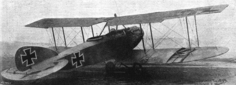
Three-quarter rear view of the Albatros biplane.
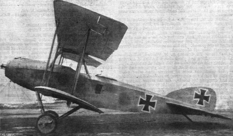
Side view of the Albatros biplane.

Three-quarter front view of the Albatros biplane.
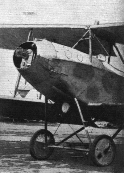
THE ALBATROS C.V-TYPE BIPLANE. - The chassis and engine, showing the gearing to the tractor screw.

Front view of the Albatros biplane.
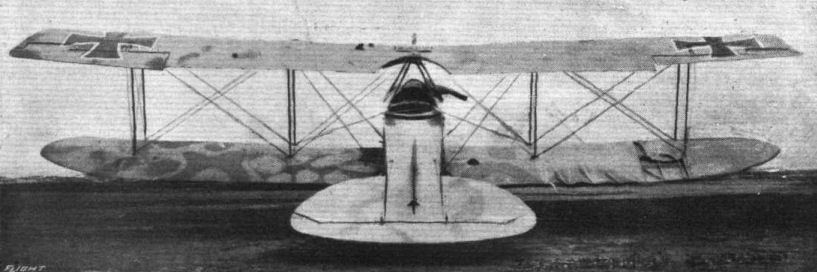
Rear view of the Albatros biplane.
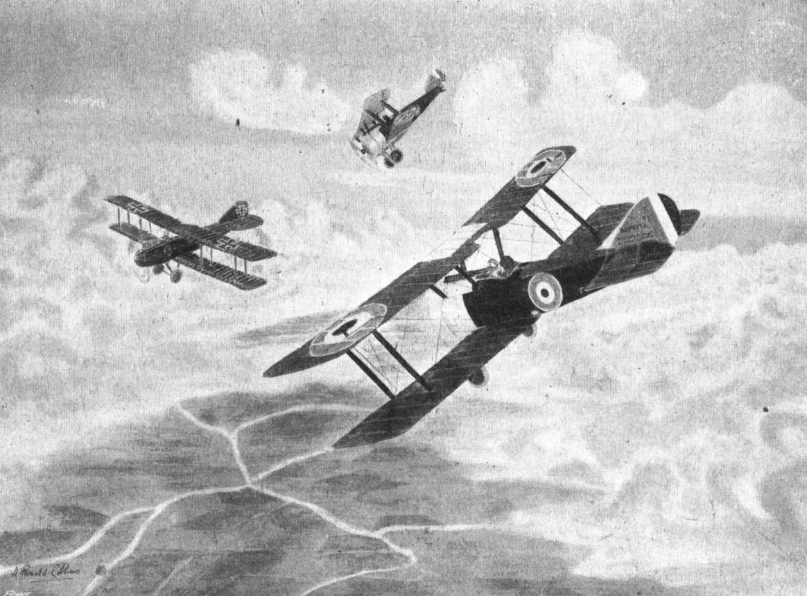
CORNERED. - An Albatros C5 caught by a couple of British machines.
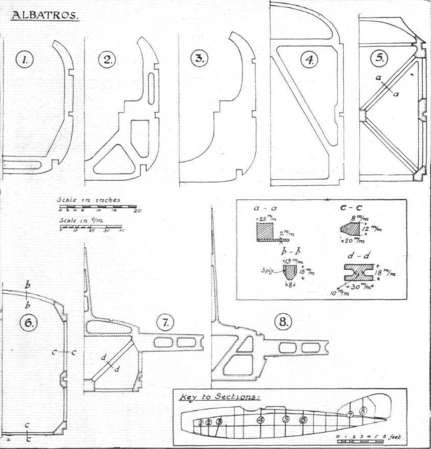
Fig. 1. - Half sections of some of the more important bulkheads of the Albatros fighting biplane. Inset, dimensions of some of the members.
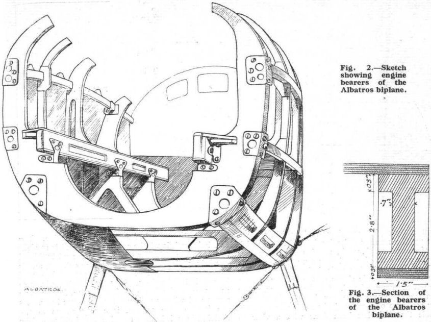
Fig. 2. - Sketch showing engine bearers of the Albatros biplane.
Fig. 3. - Section of the engine bearers of the Albatros biplane.
Fig. 3. - Section of the engine bearers of the Albatros biplane.
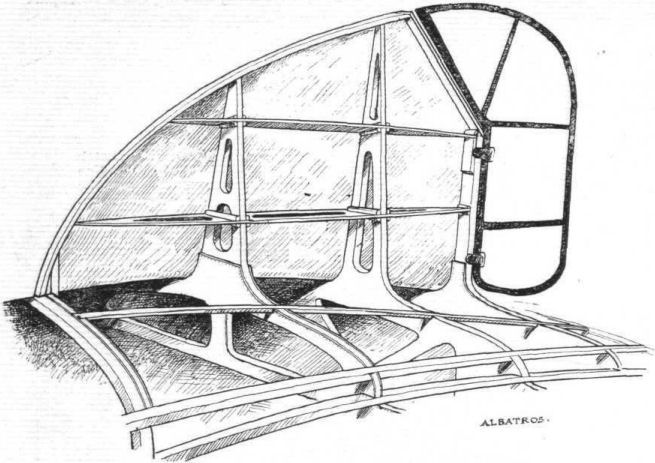
Fig. 4. - Construction of the vertical fin on the Albatros biplane.

Fig. 5. - The tail skid and its attachment on the Albatros biplane. Inset, upper right-hand corner, details of the skid pivot. Upper left-hand corner, the collar which prevents the rubber cord from slipping along the tube. These collars are apparently made up of two stampings - bowl-shaped - welded together along their peripheries. In the bottom left-hand corner is shown the bracket attaching the cross tube to the ply-wood bulkhead.
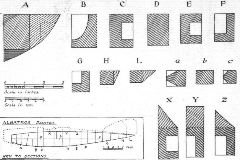
Fig. 6. - Sections and dimensions of the longerons of the Albatros biplane.

Fig. 7. - Sketch showing turnbuttons securing engine cowl to upper longerons. The bulkhead is prevented from shifting by a wood screw going through the longeron into the bulkhead.
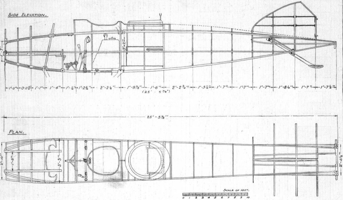
Fig. 8. - General arrangement of the Albatros body. Side elevation and plan to scale.
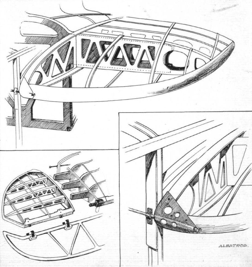
Fig. 9. - Sketches of the tail plane and its attachments on the Albatros biplane.
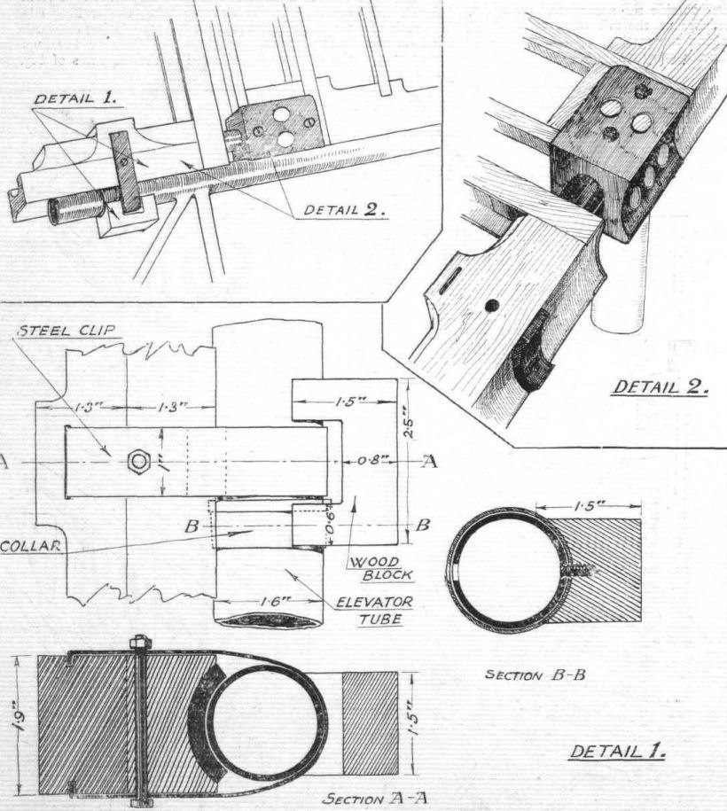
Fig. 10. - Details of the tail plane and elevator attachment on the Albatros biplane. In the upper left hand corner a view from above of the fuselage stern post, the tail plane trailing edge, and the elevator tube. In the upper right hand corner is shown the attachment of the trailing edge to the fuselage. Bottom: details of the steel clip bearings for the elevator tube; also the wood block to which the elevator fabric is attached around the hinge. The attachment of this wood block must be attended with some difficulty, as the wood screw and screw driver have to be inserted through a hole in the opposite wall of the steel tube. Probably a special tool is employed.
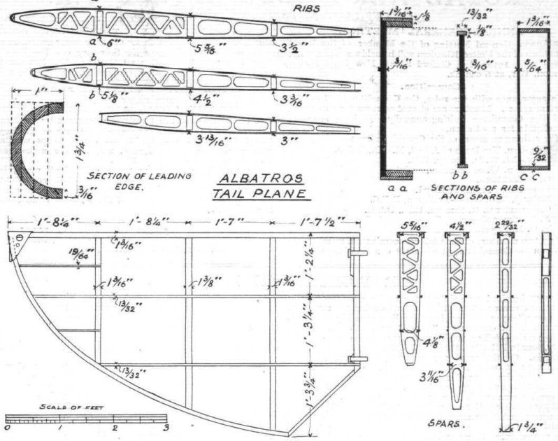
Fig. 11. - General arrangement and dimensions of the members of the tail plane on the Albatros biplane.

Fig. 12. - The main petrol tank of the Albatros biplane. The pilot's seat is placed in the recess, and is prevented from sliding about by the steel clips shown. On the right is shown a section of the tank, with the internal bracing rods and baffle plates. The insets show the brackets supporting the tank, and the arrangement for tightening the straps that hold the tank.

Fig. 13. - The controls of the Albatros biplane. Insets show the ball and socket joint for the control lever locking arrangement, and the hand grip with the gun trigger on the main control lever.
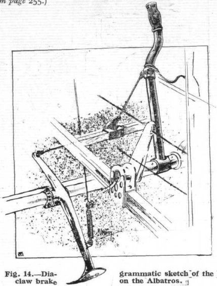
Fig. 14. - Diagrammatic sketch of the claw brake on the Albatros.
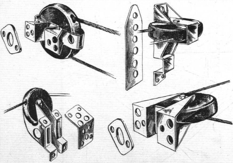
Fig. 15. - The brackets supporting the pulleys over which pass the control cables are of a somewhat complicated nature. In the top left-hand corner is shown the pulley over which the elevator cable passes after leaving the crank lever on the rocking shaft (see Fig. 13). The pulley in the top right-hand corner is bolted to the middle longeron just ahead of the tail plane, and serves to guide the elevator cable. In the bottom left-hand corner is shown the pulley mounted on the top longeron in front of the tail plane, over which passes the elevator control cable, and the pulley shown in the bottom right-hand corner guides the rudder cable in front of the foot bar, where its direction changes from a lateral to a longitudinal one.
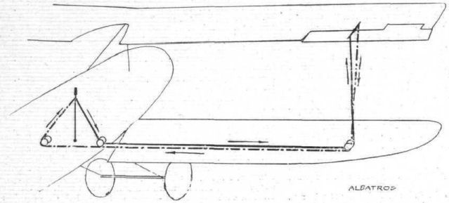
Fig. 16. - Diagram of the aileron control system of the Albatros.
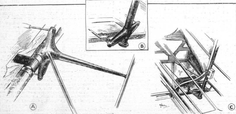
Fig. 17. - The elevator and rudder crank levers on the Albatros biplane. A shows the elevator crank lever with its ball and socket joint for the turnbuckle. In C is shown the mounting of the rudder, and in B the bottom rudder bracket and crank lever.

Fig. 18. - The machine gun and its mounting on the Albatros Fighter. The bag for the spent cartridges should be noted. When not in use the butt of the gun rests in the clip shown. The two insets show the locking devices for the gun pivot and gun ring respectively.

Fig. 19. - So as to be out of the way when the gunner is firing from a standing position, the seat on the Albatros Fighter is hinged and sprung as shown in this sketch.

Fig. 20. - Details of the bomb gear on the Albatros biplane.
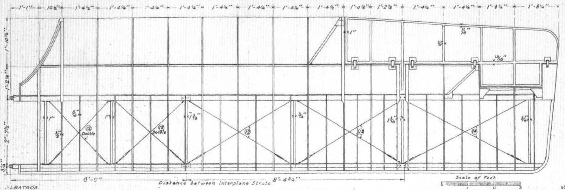
Fig. 21. - General arrangement of the upper left-hand wing of the Albatros biplane, to scale.
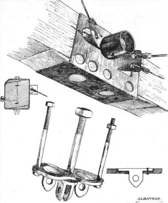
Fig. 22. - Sheet steer spar box and socket for compression tube of the upper plane of the Albatros biplane. The bottom sketch shows the attachment of the terminals for the interplane cables and struts.

Fig. 23. - Sections, to scale, of the leading edge, main spars, and false spar of the Albatros biplane.
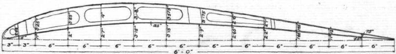
Fig. 24. - The wing section of the Albatros biplane.

Fig. 25. - The spar box and its attachment to the fuselage of the Albatros fighting biplane.

Fig. 26. - The wing flap and some wing details of the Albatros fighting biplane.
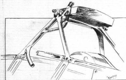
Fig. 27. - The cabane supporting the radiator and upper plane of the Albatros biplane. Note the manner of carrying the water tube through one of the cabane legs.

Fig. 28. - Sketch showing lugs on root of upper main wing spars of the Albatros.
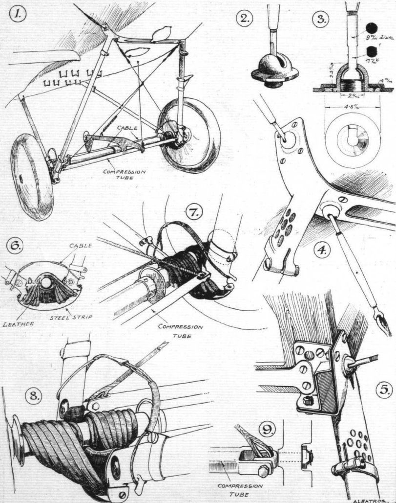
Fig. 29. - Some details of the undercarriage of the Albatros. 1. General arrangement of the undercarriage. 2 and 3. Detail of cable terminal. 4. Steel strip passing under body, to which is welded the front chassis strut socket. 5. Attachment of rear chassis strut to body. 6. Lower attachment of chassis struts and shock absorbers. 7, 8, and 9. Details of same.
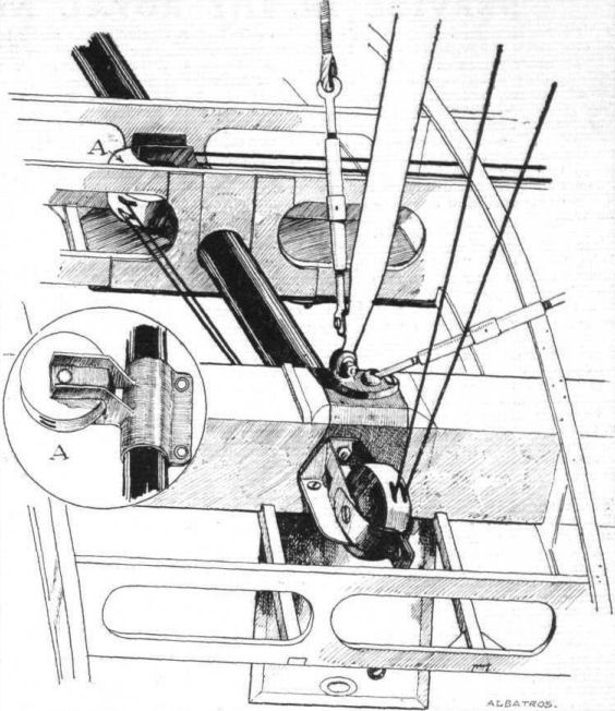
Fig. 30. - Arrangement of wing flap control cable pulleys in bottom wing of the Albatros. After passing over pulleys on rear spar, the control cables pass through the spar horizontally.

THE ALBATROS BIPLANE. - Plan, front and side elevation to scale.
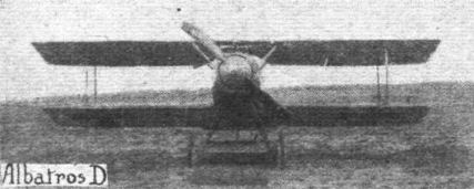
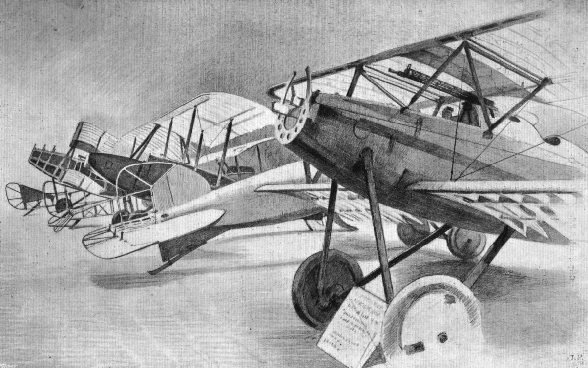
AT THE ENEMY AIRCRAFT VIEW ROOMS. - Although not including all the captured German aeroplanes, this drawing gives a good idea of the excellent arrangement of these trophies, the detail construction of which can be readily inspected owing to the machines being partly stripped as shown. Commencing with the machine in the foreground, the aeroplanes are: Albatros Scout D.V., Albatros Scout D.I., D.F.W.-Aviatik, L.V.G, Albatros Fighter, and Rumpler Fighter.
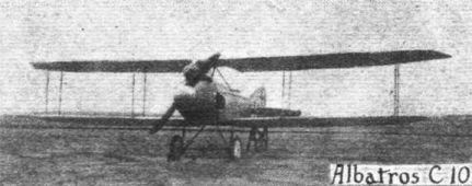

Side View of a captured Albatros Type D.V. (photographed in April, 1918).
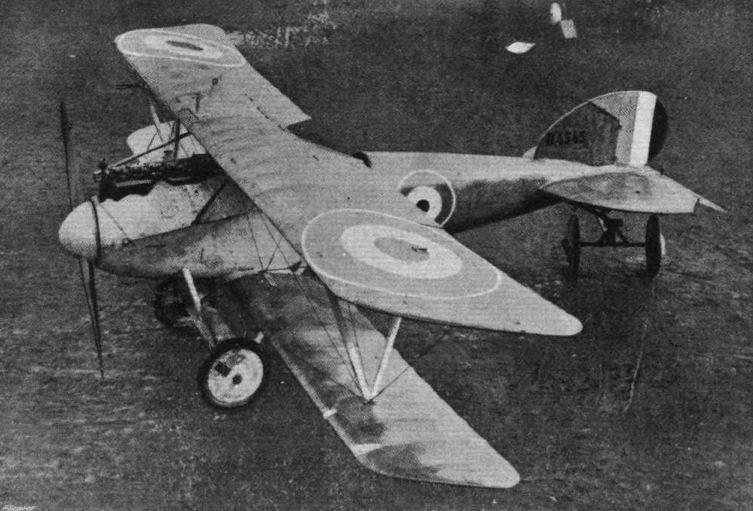
Albatros Scout D. 5 A. (G. 97), fitted with 180 h.p. Mercedes engine, showing radiator in centre of top plane.
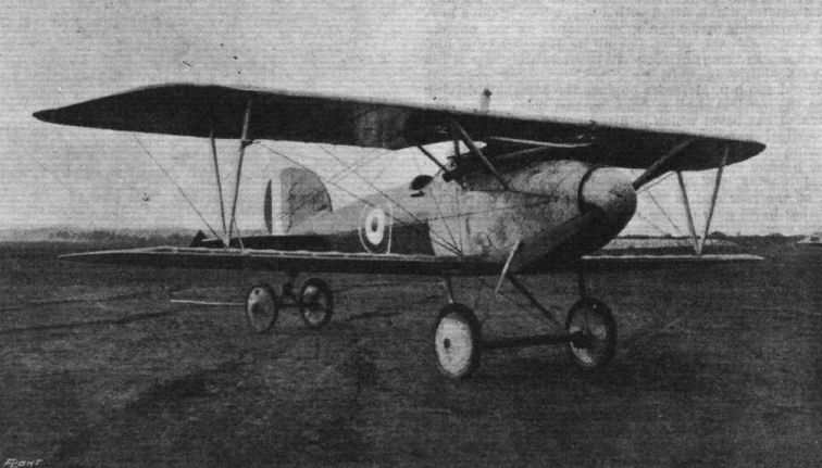
Front view of Albatros Scout G. 97, showing exhaust manifold.
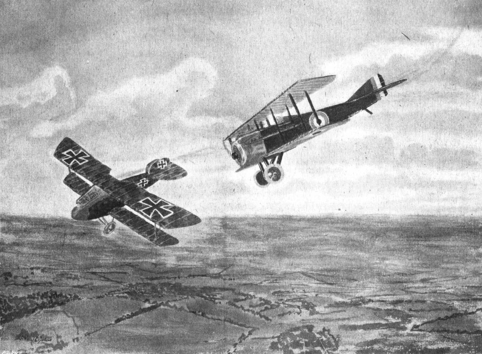
A British machine on the tail of an Albatros D.V.
AT THE ENEMY AIRCRAFT VIEW ROOMS. - Although not including all the captured German aeroplanes, this drawing gives a good idea of the excellent arrangement of these trophies, the detail construction of which can be readily inspected owing to the machines being partly stripped as shown. Commencing with the machine in the foreground, the aeroplanes are: Albatros Scout D.V., Albatros Scout D.I., D.F.W.-Aviatik, L.V.G, Albatros Fighter, and Rumpler Fighter.
AT THE ENEMY AIRCRAFT VIEW ROOMS. - Although not including all the captured German aeroplanes, this drawing gives a good idea of the excellent arrangement of these trophies, the detail construction of which can be readily inspected owing to the machines being partly stripped as shown. Commencing with the machine in the foreground, the aeroplanes are: Albatros Scout D.V., Albatros Scout D.I., D.F.W.-Aviatik, L.V.G, Albatros Fighter, and Rumpler Fighter.
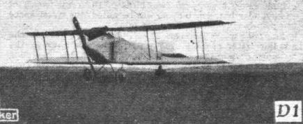
Flight, July 25, 1918.
A FOKKER BIPLANE OF RECENT TYPE.
ONE of the most interesting additions to the rapidly growing collection at the Enemy Aircraft View Rooms is a Fokker biplane of the D VII type, built, according to a pencilled date on one of the wing spars, in April of this year. The date is 24, IV, 18. The machine is thus one of the most recent to be exhibited, and is of interest on that account, as well as because of the originality of its design. Except for the fact that it is a biplane, the new Fokker product is very similar to the triplane described in our columns recently. The booty construction is the same, and the "wireless" wing design is very similar to that of the Fokker triplane. There is one notable departure, however; the engine fitted has evidently been a stationary water-cooled one, probably a 180 Mercedes.
The body of the Fokker biplane is built throughout of steel tubing, the method of joining the struts and cross members to the corner rails being the same as in the Fokker triplane, and the tubular quadrants serving as an anchorage for the cross-bracing wires being also exactly of the same type as in the previous machine. The wire bracing, as before, is simply doubled over the terminals, and only a single strainer being employed in each double wire. The tail plane and elevator are similar in shape and construction to those of the triplane, to the description of which we would refer our readers for details. The rudder is balanced, as in the triplane, but is preceded by a triangular vertical fin, which has probably been necessitated by the larger water-cooled engine, which gives a deeper body in front. The vertical fin is chiefly remarkable on account of the fact that it has its front attachment slightly off-set to the left, probably to counteract the tendency, caused by the torque, to turn to the left.
The pilot's seat is similar to that of the triplane, and is provided with the same wing nuts for quickly adjusting its height to suit individual pilots. In the machine exhibited, the control lever is missing, but from the parts remaining in place it would appear that there has been a forked lever pivoted on a longitudinal rocking shaft, which in turn carried the cranks for the aileron control cables, which pass over pulleys in the top plane in the manner illustrated in our description of the triplane.
The engine, which, as we have already pointed out, has been of the water-cooled type, is mounted on a structure built entirely of steel tubes. The two engine bearers are large diameter tubes, supported from the corner rails by small diameter tubes apparently of very light gauge. The tanks are placed immediately behind the engine, the right-hand compartment of the large main tank carrying the oil, and the left-hand compartment the petrol. A Vee-type radiator of honeycomb formation is built into the nose of the body, and is provided on the inside with a shutter for adjusting the cooling.
The under carriage is of very similar design to that of the triplane, the axle being enclosed in a wing section of three-ply wood. The shock absorbers are of the spiral spring type, and are covered, in by a woven casing. A feature of the Fokker construction, both as exemplified in the triplane and in the present machine, is the large amount of welding employed, and the manner of employing it. After an examination of the biplane, one is apt to come to the conclusion that the designer of the Fokker biplane places implicit faith in has welders, and, we are bound to admit with very good cause. The welding is excellently done throughout the machine, but the way the designer has seen fit to employ the welded joints is not above criticism. Thus, on examining the undercarriage, one finds that the lug - a simple forked arrangement - to which the cross bracing cables of the front bay are attached, is simply welded to the wall of the chassis strut without any internal reinforcement. The result, as regards one of the lugs, has been that in the shock of landing the lug has pulled out bodily a large triangle of the strut wall. The welded joint itself has remained intact, but it appears probable that the welding process has weakened the metal of the strut wall so that under the sudden stress of a rough landing this part gave way first, leaving the joint itself intact. This speaks well for the welder, but less so for the designer.
With regard to the wings of the Fokker biplane, these have been designed on the "wireless" principle, as in the case of the triplane. There is this difference, however, that whereas in the triplane the two spars were placed so close together as to form a single box, they are quite separate in the biplane, owing, no doubt, to the greater chord, which with its consequent greater travel of the centre of pressure, made it necessary to place the spars farther apart than could conveniently be done with the single-box arrangement. Each of the spars is built up of spruce flanges, connected on front and rear faces by three-ply webs, the whole forming a box. Both spars taper in a vertical as well as in a horizontal plane. The spars of the upper wing are of uniform width and depth over the portion between the body struts, and taper, from the point of attachment of these struts, to the wing tip, both in front elevation and in plan. The lower wing spars are of uniform section for the width of the body, and hence taper with a straight taper to the tips. The wing section appears to be similar to, but an enlarged edition of, that employed in the triplane. It is extremely deep compared with any modern standard, about 9 1/2 ins. being the maximum thickness of the top plane. The bottom plane, which is of smaller chord, appears to be a geometrical reduction of the top one, and is of considerably smaller chord. The actual dimensions have not yet been ascertained, as the machine in question is very considerably damaged, but we hope to refer to it in more detail at a later date. As far as can be; ascertained at present, the chord of both wings was uniform from root to tip, which fact would appear to indicate that the section from point to point varies from one of very great depth and thickness in the centre to one of more orthodox section near the tips. The aerodynamic effect of this would be of interest, and we cannot in this connection refrain from again urging, as we have repeatedly done in the past, the advisability of having tests made on all available enemy aerofoil sections and the results published. A section like the Fokker is not generally credited with any very high efficiency, but the mere fact that it has been retained in a design, examples of which have been built not more than three months ago, would certainly appear to indicate that it has not been found in practice to be so inferior as to outweigh any other advantages that may attend its employment.
The wing ribs of the Fokker biplane are somewhat similar to those of the triplane, but a difference was noticed in the construction of the flanges. In the triplane the thin three-ply web was accommodated in a narrow groove in the top and bottom flanges, but so narrow was the web that quite 50 per cent, of the tacks missed the web altogether and simply served to weaken the flanges. In the biplane it is not, therefore, surprising to find that an attempt has been made to eliminate this defect. This attempt has taken the form of the employment of a two-piece flange instead of the old grooved one-piece flange. Instead of vertical tacks the two halves of the two-piece flanges are held together and to the thin web by transverse tacks driven through alternately from right and left, and riveted over.
The manner of supporting the top plane is somewhat different from the method employed in the triplane. No wire bracing whatever is used, the necessary transverse rigidity being provided by the arrangement of the body struts. Sloping outwards from the body is a system of struts, all stream line steel tubes. One strut runs from the lower corner rail of the body to the rear spar. A set of three struts unite in a welded joint secured to the top spar by a single bolt. Each of these three struts is welded to a portion of the body, so that when the top plane is removed, a pyramid of steel tubes remains in place on the body, sloping upwards and outwards from the sides. The front one of these struts is welded to the tubular engine bearer, projecting through an opening in the metal body covering. The middle strut is welded to the bottom corner rail at the point where is, attached the front strut of the undercarriage, and the third strut is also welded to the bottom -corner rail, or, more correctly speaking, to a rail running above the spars of the lower wing, at the point where it is crossed by the front spar. The upper front spar is thus rigidly secured, whereas provision has been made for an adjustment of the angle of incidence by fitting into the end of the strut running from the rear spar to the lower body rail a threaded eye bolt fitting into a socket on the lower rail. Incidentally it might be mentioned in this connection that the upper plane is marked "Anstellwinkel 0·" (angle of incidence 0·.) Whether or not the bottom plane is also set at no angle of incidence we have not yet been able to ascertain. The mounting of the bottom plane is slightly different to that of the bottom plane of the triplane. In the latter provision was made for a slight adjustment of the angle of incidence, but in the biplane no such arrangement is to be found, the spars being rigidly attached to the body corner rails.
Only one pair of inter-plane struts connect the upper and lower wings on each side. These are in the form of an N, the joints between the members being welded. The joints between the legs of the N and the wing spars are in the form of ball and socket joints, those for the front top spar and rear bottom spar being fixed, while threaded bolts screwed into the end of the struts meeting the upper rear and lower front spars provide means for adjusting the incidence. No lift or landing wires are fitted, the deep spars being relied upon to resist the bending moments without external aid. Internally the wings are drift-wired with solid circular section steel wire, of 'heavy gauge, but not in duplicate. It was noticed that one of the lugs to which a drift wire was attached had sheared through, but we should hesitate to say that this necessarily indicates that here was a weak point regarded from the point of view of flying stresses, as the wing had evidently been badly damaged by the machine turning over on landing.
The armament of the Fokker biplane consists of two Spandau guns mounted on top of the body and synchronised in the usual manner to fire "through" the propeller.
As regards the covering of the Fokker biplane this is chiefly remarkable, in the specimen under review, on account of the colours in which it is painted. The front portion of the body and the top surface of the top plane are painted a deep vermilion, while the rear portion of the body is painted white. The lower surfaces of the top plane and the bottom plane are camouflaged in the usual German manner by a printing in different colours of lozenge-shaped figures.
The tail plane and elevator are painted black, with the exception of a parallel portion of the top surface, which is painted white like the body.
As already mentioned one of the wing spars bears the date 24.IV. 18, and another spar is branded "Gebr. Perzius, Flugzeug Abteilung." Painted in red stencil on the rear face of the bottom spar is the wording D VII Fl. No. 1450.
Flight, October 3, 1918.
THE FOKKER BIPLANE, TYPE D VII.
[From the Technical Department, Aircraft Production, Ministry of Munitions, we have just received an official report on the Fokker biplane. Except for extreme pressure on our columns the first instalment of our own description of this machine would h<...> appeared in last week's issue of "FLIGHT," the greater part of the material for this article being made-up ready for publication. After carefully perusing the official report we have decided to adhere to our original intention of publishing our own description of this machine, preceded by certain items in the official report compiled from sources not available to the general Press. At the same time we feel obliged to point out certain discrepancies between the official report and our own. These occur mainly in scale drawings of the machine. Thus in the side elevation the inter-plane struts are shown, in the official drawing, as approximately parallel whereas as a matter of fact they are very far from being so. This mistake has apparently been caused by placing the front side of the lower plane too far forward, bringing it into line with the chassis strut attachment, while, as a matter of fact, it is placed slightly farther aft in the recess in the body, as clearly indicated in "FLIGHT'S" side view. Fig. 1. In the same manner the rear spar of the bottom plane appears to have been placed too far aft. Turning our attention to the front elevation of the official general arrangement-drawing, it is found that the top wing is represented as having its top surface set at a negative dihedral and its lower sur<...> at a positive dihedral angle. This does not tally with our own measurements, which show that the top surface of the top plane is perfectly straight, the lower surface sloping up to it. Again, the taper of the top spars is shown in the official drawing to ex<...> right from centre line to tip. This is not correct. The top spars are parallel between the points of attachment of the struts slop<...> outward from the body, tapering from these points to the tip. This may appear only a small matter and one not worth drawing attention to. It should be remembered, however, that a change in the particular example referred to might, and in all probabi<...> would considerably affect the stability and manoeuvreability of the machine, and the matter may not, therefore, be of as <...> consequence as might be imagined. In the official plan view of the Fokker there are one or two points which are not strictly accu<...> such as showing the upper wing tip with a sharp corner at the leading edge instead of rounded off, and a straight leading edge instead of one slightly swept back. With this, however, we are not quarrelling, as the rounded corner woud be of m<...> importance, and the sweep-back, as pointed out in our description, may be intentional, or, on the other hand, may have be caused by straining the wings badly. We have no desire to find fault merely for the sake of it, but when it comes to such serious item as the off-setting of the vertical fin, which is shown in the official plan view as being on the centre line, while a matter of fact its front end is off-set to port, we do think this is inexcusable, especially as it is quite correctly pointed out in the text of the report that the biplane "has a triangular fin with foremost point is fixed an inch or two to the port side of the centre line of the machine," and a sketch, Fig. 12, has been drawn to illustrate this feature.
The text of the official report is quite accurate, as jar as have been able to judge, and the respective sketches are excellent with one exception. Fig. 15 in the official report is intended to show the engine bearers and their mounting. Whether it does with any great success or not does not greatly matter to <...> argument, but what does matter is that important tubes form part of the bearer and body structure have been omitted. <...> to illustrate our point we are publishing the official <...> well as our own (page 1114). - ED.]
THE following data, relating to the performance of this t<...> of machine and the detailed particulars of the weights, wh<...> are reproduced from the official report, should be of considerable interest. It will be seen that these data have been compiled from various sources, some being obtained from the machine described, while others have been based upon figures relating to machines captured by the French :-
The British No. of the machine is G/2B/14, and the German No. is Type D7 F.N. 1,450; maker's No. 2,455.
It was brought down north of Hazebrouck on June <...> 1918, by a British S.E.5a, and is a single-seater fighter.
This aeroplane presents features of very grea<...> whether viewed from the standpoint of aerodynamic ties or of actual construction. The machine which has been the subject of investigation was unfortunately rather extensively damaged, thus making absolute accuracy of description difficult, and trials of performance impossible.
A similar machine, however, has been tested for performance by the French authorities, who have issued the following report :-
Altitude. Time of climb. Speed at this height,
metres feet m. s. m.p.h.
1,000 3.281 4 15 116.6
2,000 6,562 8 18 114.1
3,000 9.843 13 49 109.7
4,000 13.124 22 48 103.5
5,000 16,405 38 5 94.9
The following data regarding weights is taken from a French source :-
Weight of fuselage, complete with engine, &c 1,322.2 lbs.
Weight of upper wing with ailerons 167.2
Weight of lower wing 99.0
Weight of fin and rudder 6.6
Weight of fixed tail plane 17.6
Weight of elevators 9.9
1,622.5
[The schedule of principal weights given below is the result of weighing the actual components mentioned, which were taken from the aeroplane allotted G/2B/14]
A different French report gives the following figures, which are taken from inscriptions found on one of the Spandau <...> captured Fokker of the same type :-
Weight, empty 1,540 lbs.
Permissible load (useful load and fuel) 396 lbs.
Schedule of Principal Weights. lbs. oz.
Upper wing, complete with ailerons, pulleys, bracing
wires, fabric and strut fittings 156 0
Lower wing (no ailerons fitted), complete with strut
fittings and fabric 97 0
N strut between wings 6 9
Straight strut, between fuselage and trailing spar of
upper wing 2 8
Aileron frame, with hinge clips, without fabric 4 8
Rudder frame, with hinge clips, without fabric 4 11
Fin frame, without fabric 1 14
Tail planes (complete in one piece), without fabric 12 6
Elevators (complete in one piece), without fabric 11 2
Radiator, empty 48 0
Undercarriage strut, each 2 10
Undercarriage axle, with shock absorber bobbins 18 2
Bobbin, each 0 7
Shock absorber, each 3 9
Undercarriage (complete), without wheels and tyres,
and without plane, but including struts 29 4
Aluminium tube, forming rear spar of undercarriage
plane 1 8
Wheel, without tyre and tube 11 8
Tyre and tube 9 4
Tail strut 1 15
Fabric, per square foot, with dope 0 1
Bottom plane compression rib 0 15
Bottom plane, ordinary rib 0 11
Top plane ordinary rib, at centre of plane 1 0
Bracket, with bolts, attaching top plane to fuselage
struts 1 11
Main spar, top plane, including fillets for ribs, per
foot run in centre 1 12
Owing to tapering ends the average weight per foot of the spars will be slightly less than this figure.
Fabric and Dope.
The fabric is coarse flax, coarser and less highly calendered than the type usually met with, and a good deal heavier.
It is colour-printed in the usual irregular polygons. The bright red paint, mentioned below, is removable by alcohol, but not soluble in it, coming off as a skin under the treatment.
Under the paint is a dope layer - an acetyl cellulose. Neither paint nor dope presents unusual features.
Weights
Paint 92.0 gms. per sq. m.
Dope 68.1 "
Fabric 143.6 "
303.7 "
Strength 1,772 k/m.
Extension 7.0 per cent.
Where the wings are not painted, the fabric is covered with a thin layer of dope only.
[With these comments upon and extracts from the official report, we now commence our own description, in its original form, of the Fokker biplane.]
****
[Of the machines now on view at the Enemy Aircraft View Rooms, Agricultural Hall, Islington, few are of greater interest than the Fokker biplane, D VII. This is mainly due to the fact that this machine is of recent manufacture (the wings bear the stamp 24. IV. 18) and is at present employed in considerable numbers on the Western Front, but also on account of the unusual design of some of its more important component parts. In our issue of July 25th, 1918, we published a more or less diagrammatic perspective drawing of this machine, the set of wings then available for inspection being in a very damaged and incomplete condition. At the same time we gave a brief description of the main characteristics, which will, therefore, be familiar to readers of "FLIGHT." A complete set of main planes is now available, and by the courtesy of the authorities we have been permitted to inspect the machine and to prepare the following drawings, sketches, and description. - ED.]
As its class letters (D VII) indicate, the Fokker biplane is of the single-seater fighting type of machine. As distinct from all previous types of Fokker machines it is fitted with a large water-cooled engine, with the radiator mounted in the nose of the body. As regards its wings the Fokker biplane forms a compromise between the one-and-a-half- plane originated by the Nieuport firm and the ordinary single-strutter machine with both planes of the same span and chord. In the Fokker the upper plane is considerably greater in area than the lower, while the difference between the two is not quite so pronounced as in the Nieuport type. The single pair of interplane struts form the link of similarity to what we have termed the ordinary single strutter, inasmuch as they are not of the Nieuport Vee type, but follow general practice with the one exception that they are braced by a single diagonal tube instead of the more usual incidence wires.
From the general arrangement drawings it will be seen that the upper plane is mounted comparatively low in relation to the top of the fuselage, thus giving a fairly good view forward. Owing to the method of mounting the top plane there are no bracing wires running across the top of the body, interfering with the two machine guns, which are mounted above the body. As pointed out in our preliminary report on this machine, it is of the "wireless" type as regards its wing truss, no lift wires or landing wires being provided, although internal drift wires are fitted in the wings. This feature has been made possible by choosing an extremely deep wing section, very similar to that of the Fokker triplane described in our issue of May 30th, 1918, which gives ample room for a spar deep enough to take the wing loads without the external aid of lift wires. The construction of the wings will be dealt with in detail later, but at the present juncture a few words regarding the aerodynamic side of the question may not be amiss.
When describing the Fokker triplane we expressed a doubt as to whether all things considered, the deep wing section was "worth while." One has become accustomed to regard such a deeply cambered section as liable to have a high resistance factor, although its lift coefficient may be, and probably is, high. At the time we strongly urged that the N.P.L. should carry out wind tunnel tests on a model of the section to ascertain what, exactly, are its lift and drag coefficients and other characteristics. Up to the time of writing we have no information to the effect that such tests have been made. Nor are we prepared to express the opinion that tests would necessarily reveal any astonishing and unexpectedly good features. When, however, we see such a section employed in a machine of so recent manufacture as April of this year, we confess that we do think there is reason to suppose that the section cannot be so very inferior; otherwise why continue to employ it? Surely the scientific German mind would not tolerate its retention just to please a designer of a "freak" machine? One is therefore forced to the conclusion that the enemy has found that the wireless, wing truss with the (possibly) larger resistance section has its advantages over low-resistance sections plus their wire bracing.
That the particular spheres of flying in which the section scores may be climbing and a high ceiling we should be the last to deny, but even so the enemy must, after weighing the cons and pros, have come to the result that these two attributes are of more importance than mere speed, if the latter is obtained at the cost of the former. Without the wind tunnel tests, or actual tests of a full size machine, one does not even know whether or not the Fokker biplane does have a comparatively low maximum speed. We would therefore again urge that tests be carried out in the wind tunnel, and that the results be made known to British manufacturers and designers.
An examination of the plan view of the Fokker biplane will show that ailerons are fitted to the top plane only, and that even so are of an area which would appear to be wholly inadequate, as compared with those of machines of more orthodox design. Yet from what one can learn from pilots who have seen the actual machines at close quarters they appear to be very quick on the lateral control. Why is this? Again, one can only come to the conclusion that in some way the peculiar wing section must be responsible for the efficiency of the ailerons. Whether this be due to the deep section as such, or whether to the fact that the wings are very much tapered in thickness from root to tip is difficult to say. It appears probable that it may be in some measure due to both factors. The fact remains that sufficient lateral control is apparently provided by ailerons of ridiculously small area.
It has already been mentioned that the wing spars of the Fokker biplane taper from root to tip. The form this taper takes will be to a certain extent apparent from the front elevation of the machine, but a more detailed reference to it may be of assistance. The upper wing spars, front as well as rear, have their top surfaces perfectly straight. The bottom surfaces are parallel to those of the top for a length extending between the points of attachment of the outward sloping body struts. From this point to the tip the lower surfaces of the spars slope upwards. The effect of this arrangement is to give the lower surface of the top plane a dihedral angle, the top surface being straight.
As regards the lower wing spars, their taper appears to be approximately symmetrical, that is to say. Both surfaces of the spar are parallel for the short length resting inside the body, while from the side of the body to the wing tip the upper surface of the spar appears to slope down to about the same extent as the lower surface slopes up. In the machine under review both wings appear to have a sweep back of about one degree or so, but whether this was present originally or whether produced by excessive strain we have not been able to ascertain. The remaining component members of the machine do not present anything particularly unusual, and we can therefore now turn our attention to the :-
Construction.
Body. - As in the case of the triplane, the body of the Fokker biplane is built of steel tubing throughout. The general arrangement and most of the details will be clear from the side elevation and plan, Fig. 1. The four corner tubes or longerons vary considerably in section as one progresses from nose to stern. Their outside diameter at any point is indicated in the drawings, but we have not been able to ascertain the thickness of the tube walls, as this would have necessitated cutting a great number of rails and struts. Apparently the tubes are of very light gauge, and are joined, a larger to a smaller, at the points where occur the body struts. The struts are attached to the longerons, as in the triplane, by welding, the joint being particularly well made. As a matter of fact it is only this excellent workmanship that mates this construction feasible. Whether the welding has been done by the oxy-acetylene method, by oxygen and hydrogen, or by electricity is impossible to say. The construction points unmistakably to the body framework having been welded in place over jigs, and as one spoiled joint would ruin the whole framework it appears probable that a considerable amount of control of the temperature of the flame used would be an advantage. Possibly, therefore, the welding has been done by electricity. Whatever the method, there can be no doubt that the welding is excellently done, and, unless an entirely new method has been evolved by the enemy, could only have been entrusted to highly skilled workmen.
It is not only in joining the struts of the body to the longerons that welding has been employed, but also to a great extent for securing members which do not, strictly speaking, belong to the main body framework. For instance, the three stream line steel tube struts which connect the front spar of the top plane with the body are welded at their lower ends to various portions of the body frame. The front one of these struts is welded to the tubular engine bearer, while the other two are welded to the upper and lower longerons respectively. Thus when the wings are dismantled these struts remain in place on the body, a fact which would, one imagines, render them liable to damage during transportation In order to give an idea, of the amount of skilful welding necessary in the Fokker body we show, in Fig. 2, a complexity of welds, all occurring at one joint. There are no less than seven members joined here by welding, not counting the socket for the front chassis strut, which might, as a matter of fact, have been included as it is attached to the longerons by welding.
In conformity with the rest of the design of the body of the Fokker biplane, the engine bearers and the framework connecting them with the fuselage are in the form of steel tubes. Of these there are a considerable number, some plain, straight tubes and others bent to the shape of a letter U. The arrangement of these bearers and their supports is shown from two points of view in Fig 3. The inset shows one of the split collars or slips by means of which the engine is secured to the two bearers.
Fig. 4 shows some constructional details of the body and tail planes of the Fokker biplane. The fixed tail plane as well as the divided elevator are built up of steel tubes, the general arrangement being shown in Fig. 1. In the general sketch of Fig. 4 the ribs of the tail plane have been omitted so as to show more clearly other details. Like the tail plane and elevator, the rudder and its fin are built of steel tubing. The fin has the peculiarity that its front end is slightly offset to port, probably to counteract a tendency, caused by the torque, to turn to the left. This offsetting of the fin would probably result in a tendency to turn to the right with the engine switched off, but with regard to this we have no data, as the machine has not been flown by any of our pilots, being in a too damaged condition to make this expedient. The attachment of the front end of the fin to the front transverse tube of the tail plane is shown at A, Fig. 4. The detail at B shows a hinge that is very extensively used on the Fokker biplane, both for the elevator and rudder, and also for the ailerons. The construction of the hinge will be easily understood from a reference to the sketches. A sheet aluminium plate has a portion stamped out as shown to form the front half of the bearing, the remaining two strips forming the rear half. Into the space thus formed is forced a bush that provides the bearing surface for the rudder or elevator tube. The whole hinge impresses one as being very neat and simple, and the only objection that might be raised against its employment is that each hinge has to be pushed into place before the elevator or rudder ribs are welded to the tubular leading edge. As, however, everything is, apparently, done over jigs this is a matter that is easily managed while building up the control organs. The sketch at D shows the split collars used for securing the two diagonal tubes which reinforce the body frame at the point where occurs the handle by means of which the rear portion of the body is lifted when handling the machine on the ground.
The body of the Fokker biplane terminates at the rear in a sort of false stern post of wood, the last vertical tube of the body being placed some little distance farther forward. This tube, which is welded at its ends into the angle formed by the converging longerons at this point, has mounted on its upper end the attachment for the tail plane. This is in the form of a simple bolt, which does not appear to provide any adjustment for the angle of incidence of the tail plane, although it might easily be extended to do so. The front attachment of the tail plane to the top longerons is by means of two bolts passing through short lengths of tube welded to the inside of the longerons. At its lower end the vertical tube referred to above carries the attachment for the tail skid, the details of which are shown at F. The upper end of the tail skid is sprung by coil springs and the amount of travel is limited by a cable as shown at E. The sketch at G shows the tubular quadrant to which the bracing wires of the body are attached. As in the triplane these wires are simply doubled over the quadrant, and are thus not strictly speaking in duplicate. Only a single wire strainer is incorporated with each double wire, the method of locking the strainer being as shown in the sketch.
(To be continued.)
Flight, October 10, 1918.
THE FOKKER BIPLANE, TYPE D VII.
(Continued from page 1116.)
IN our last instalment the construction of the Fokker biplane body was dealt with in detail. Before turning our attention to the wings, it may be as well to refer briefly to some of the equipment and accessories which, although being attached to or mounted in it, do not form a part of the main body structure.
The Controls.
In principle the controls of the Fokker biplane are very similar to those of the triplane described in our issue of May 9th, 1918, but some of the details are somewhat different. Fig. 5 is a perspective view of the controls. A longitudinal rocking shaft is carried in two bearings, formed by clips bolted to transverse tubes in the bottom of the body. The control column, which is a steel tube tapering towards its upper end, fits into a tapering socket that is in turn welded to the collar surrounding the longitudinal rocking shaft. The downward projection of the column is similarly welded to the bottom of the collar. It will thus be seen that a welded joint is relied upon for the main elevator cables, a feature which places great reliance on the excellence of the welded joint.
The longitudinal rocking shaft has a forward projection, on which are carried the two crank arms operating the aileron cables. These two cranks are formed of sheet steel bent over so as to form a stream-line section with its sharp edge pointing downwards. They are placed at an angle of about 100· to one another, and are, in addition, staggered, the port arm being in front of the starboard one. The rudder bar, as in the Fokker triplane, is in the form of a steel tube secured to its collar as shown in the sketch and pivotting on a vertical tube secured at its lop to one of the fuselage cross struts, and at the bottom to one of the bottom cross struts via a fork formed by two short tubes as shown, in order to clear the longitudinal shaft. The pilot's feet are prevented from slipping off by the tubular guards welded to the foot bar. The method of anchoring the rudder cables to the foot bar is interesting. On each side a short tube is welded to the side of the foot bar, and through this tube is passed a bolt which also goes through the arms of the stirrup or shackle that forms the final attachment for the rudder cables. Here again the controls put the -welded joints under tension. In the triplane the shackles passed over the foot bar, the vertical tubes being welded to the front of the bar, thus avoiding the tension on the welded joint. The method of making the shackles is very simple, as shown in the detail sketch of Fig. 5. A short length oа tube of small diameter has its ends slotted and flattened out, holes being provided in the flat portion for the vertical bolt. The tube is then bent and the shackle is finished. In Fig. 5. the floor boards have been omitted on the starboard side to show the controls, but under the left foot guard will be seen a segment of aluminium which serves to protect the floor against the constant rubbing of the pilot's heel. Another such guard is, needless to say, fitted under the right foot.
The grip in which the control column terminates at its upper end is quite different from that found on the Fokker triplane. In the present machine the grip consists of a small piece of wood, shaped to fit the fingers of the right hand, and having a slight hollow at the top for the thumb. The triggers for the machine guns are not pushed by the thumb as in the majority of other machines, but are pulled by the fingers towards the grip. On the port side of the control lever is mounted a Bowden control for the throttle. The handle of this had been knocked off in the machine examined, so it has been impossible to ascertain its exact shape. It has therefore been shown dotted in the sketch. This lever does not operate the throttle direct, but is connected to the proper throttle lever mounted on the port side of the body by Bowden cables. The object evidently is to enable the pilot to work the throttle from the control lever during a fight, instead of having to shift his hand and possibly fumbling about for a few seconds before getting hold of the main throttle lever. It will be noticed that no provision has been made in the biplane for locking the elevators in position, the necessity for doing this having apparently been avoided by the arrangement of the gun and engine controls.
Before leaving the subject of controls reference may be made to the lateral control system of the Fokker biplane, which is somewhat unusual. In order to facilitate an explanation of the principle on which the aileron control is based, we have prepared a diagram. Fig. 6, which shows, in purely diagrammatic form, the paths followed by the aileron cables over the various pulleys. It will be noticed that the lower plane has not been included in the diagram. This is due to the fact that nowhere do the aileron control cables pass over or through the bottom plane, as is usually the case in German machines, specially when the typically German aileron crank levers, working in slots in the top plane, are fitted. In the Fokker biplane the crank levers are vertical as in British machines. So far as one is able to judge, the object which the designer had in mind when working out this control system was to provide positive control, not only to the aileron that is being pulled down, but also to that being pulled up. The manner in which this object has been attained in the Fokker, will be understood by a reference to Fig. 6. In the explanation to follow we shall refer to the cable pulling down the ailerons as a positive cable, and to that pulling up the ailerons as the return cable. In the diagram the two sets of cables have been drawn differently, the positive cable being shown by a chain dotted line, while the return cables are indicated by a plain dotted line From the crank on the longitudinal rocking shaft in the fuselage the positive cable runs through a guide on the top longerons (not shown), over a pulley mounted on the top rear spar, along the spar, around another pulley, and hence to the lower aileron crank. The return cable from the same crank arm in the body runs through the same guide on the top longeron, to a pulley at the side of that for the positive cable, along the spar in the opposite direction to that of the positive cable, over another pulley and hence to the top crank of the aileron. The arrows in the diagram will help to make the arrangement clear. Thus, when the control lever is pulled to port, the positive cable pulls down the starboard aileron, and the return cable pulls up the port aileron.
Tanks.
As far as we have been able to ascertain, all the tanks carried on the Fokker biplane have been incorporated in one single tank of brass. The oil tank occupies the extreme starboard side of the tank, then comes a small reserve tank, and on the port side, partitioned off from the reserve tank, the main tank, which, judging from the lines of rivets visible on the outside, is divided up into two compartments communicating with one another. From external measurements the capacity of the various tanks is approximately as follows: Oil tank, 3 gallons; petrol, 20 gallons. These figures are only approximate. Both petrol tanks work under pressure, supplied by two pumps, one driven by the engine and the other hand operated. As shown in Fig. 7, the mounting of the tank is rather unusual, there being no supporting bands passing underneath the tank, which is slung from the top cross tubes of the body by means of brackets and bolts, as shown.
Instruments.
The instrument board of the Fokker biplane is not a very elaborate affair, the "gadgets" being few in number, compared with the instrument boards of some of our own machines. Especially noticeable in all German machines, with the exception of some of the later Gothas, is the absence of speed indicators. In the case of the Fokker it is possible that some of the instruments may have been removed, although there are no indications that more have been fitted than those now in place on the machine. On the port side of the instrument board is the hand magneto, surmounted by its switch. In the centre are the two petrol pressure indicators, and underneath them the petrol and pressure cocks. In the top right-hand corner is a grease pump for the water pump. Mounted on the starboard body struts is the hand-operated petrol pump and the compass. The mounting of the latter is somewhat unusual, as shown in Fig. 8. A small piece of three-ply wood is clipped at its upper end to one of the body bracing wires and at its lower end to the bottom longeron. Mounted on this is the bracket that carries the compass. The base plate is provided with a curved slot which allows of adjusting the placing of the compass in relation of the centre line of the body. A brass bar of square section projects downwards from the base plate, and on this are mounted the adjusting magnets. These are evidently placed initially by experts, and the pilot is not permitted to interfere with them in any way, as they are locked in position and sealed with a lead seal. One would imagine that in an all-steel body like that of the Fokker, the size and number of the adjusting magnets necessary would be considerable; yet this does not appear to be the case.
The throttle and ignition control levers are placed at the pilot's left hand. As already pointed out when describing the main controls, the throttle lever is connected up with Bowden cables to a throttle lever on the control column. The main throttle lever operates the throttle via a series of rods and cranks. The ignition is similarly controlled.
Armament.
The armament consists of two Spandau machine guns, provided with the usual interrupter gear for firing between the blades of the airscrew. The mounting of the machine guns is indicated in Fig. 9. Each gun is provided with two supports, and a certain measure of rigidity is added by running a tube from the front support rearwards and outwards to the end of one of the top cross struts. As in other German machines, the rear gun support allows of vertical adjustment, while the front support provides for a slight adjustment laterally. The cartridge boxes are of sheet aluminium, and do not present any features of particular interest.
Radiator.
The honeycomb radiator, which is unusual for a German machine, in that it is placed in the nose of the fuselage, is of Vee shape as seen in plan. The apex of the Vee is cut off, however, forming a flat of approximately 4 ins. width down the extreme front of the radiator. The left half of the curved top of the radiator forms a small water tank, while the right half is simply a curved fairing. Provision has been made for varying - although apparently to a very small extent - the cooling by placing a small door or shutter over the starboard side of the radiator. This door, which is placed on the inside, behind the radiator, is normally allowed to trail in the line of flight, but can be pulled against a spring by means of a cable so as to lie fiat against the back of the radiator. When closed this door only covers a small portion of the radiator, less than one-third, so one does not imagine that the amount of control over the cooling is very great. The mounting of the radiator will be fairly clear from Figs. 1 and 4 in our last issue.
The Undercarriage.
The undercarriage of the Fokker biplane is of the simple Vee type, with stream-line steel tube struts. At their upper ends the struts terminate in balls fitting into sockets welded to the fuselage members, and are prevented by a short bolt from coming out of the socket. At the lower end the undercarriage struts are welded to a sheet steel box, in which is a slot for accommodating the travel of the axle. This sheet steel box also serves as a support for the short stubs to which are anchored the shock absorbers. These are of the coil spring type, enclosed in a woven covering after the fashion of rubber cord. An aluminium box, formed of sheet, connects the port and starboard boxes and serves as the main spar of the fairing, or wing section, surrounding the axle. This section was severely damaged in the machine examined, and its exact shape is therefore a matter of surmise, but it appears probable that in section it was very similar to the wings. From what little remains of it this section appears to have been covered top and bottom with three-ply wood. In addition to serving as a fairing for the axle this section probably gives a not inconsiderable amount of lift, especially when landing, when there would be a "cushioning" effect due to the proximity of the section to the ground. The diagonal bracing of the undercarriage is in the form of stranded cable in the front bay only. The cables are attached at the lower end to a forked lug welded to the wall of the struts One of these lugs, as pointed out in our preliminary description of the Fokker biplane, had pulled a triangular portion of the -strut wall out, although the weld itself appeared undamaged. At the upper end, the bracing cables of the undercarriage are simply passed around the bottom longerons and spliced. This feature was shown, incidentally, in Fig. 2 in last week's issue of "FLIGHT."
(To be continued.)
Flight, October 17, 1918.
THE FOKKER BIPLANE, TYPE D VII.
(Concluded from page 1144.)
As already mentioned the wings of the Fokker biplane form one of the most interesting features of the design, both aerodynamically and structurally. In Fig. 11 are shown four typical sections, taken at various points in the planes. The top section in the illustration is taken in the centre section of the top plane. Underneath this is a section taken on the top plane rib occurring a short distance inside the attachment of the inter-plane struts. These two sections give a good idea of the manner in which the planes of the Fokker biplane taper in camber towards the tips. It will be seen that both upper and lower surfaces of the section are flattened out towards the tip. The other two sections shown in Fig. 11 represent the lower plane rib at the root and inside the attachment of the inter-plane struts respectively. Here, it will be seen, there is no flattening out of the bottom camber, in fact it appears that the maximum bottom camber of the thinner section is slightly greater than that of the section at the root... In both upper and lower plane sections it will be observed that the distance from centre line of front spar to leading edge diminishes slightly as the tip is approached. This accounts for the sweep back referred to in a previous instalment of this article.
Constructionally the ribs are built up of solid webs of thin three-ply wood. The flanges of the ribs are attached in a somewhat unusual manner to the webs. Instead of having the flanges in one piece and grooved for the web, the flanges in the Fokker biplane are in two halves, the three-ply web passing between the two halves of the flanges and extending the full thickness of the section. The flanges are tacked together and to the web by horizontal tacks driven through and riveted over.
The wing spars are of the box type of construction, as indicated in Fig. 12, which shows the sections of all four spars in the centre, i.e., where the maximum dimensions are found. The flanges, it will be noticed, are not solid, but are built up of two laminations each. The top flanges of all four spars are so shaped as to form an approximately rectangular space between them and the bottom flanges. At the points of attachment of the spars, such as to body or to inter-plane struts, this space is filled with a distance-piece in the form of a piece of wood. The distance-piece does not, however, touch the flanges direct, a piece of wood tapering towards the ends, which are forked, being interposed between the distance-piece or packing block and the flanges. The object of this arrangement appears to be connected with shear stresses on the spars, which are disposed of gradually instead of suddenly in this manner. The rib flanges are made of pine, and are connected by thin webs of three-ply, about 1.5 mm. thick, which are glued to the flanges. The tops and bottoms of the spars are afterwards covered with a strip of fabric, which extends over the sides of the spar to past the edge of the flanges, thus acting as a protection for the glued joints. The leading edge, as in the Fokker triplane, is in the form of very thin three-ply wood, which extends back to the front spar, where it finishes off in a serrated edge having its points tacked to the spar. This feature is shown in Fig. 13. This sketch also shows the vertical triangular-section pieces of wood which reinforce the rib webs, as well as the manner of attaching the ribs to the wing spars. The trailing edge is in the form of a wire, and its attachment to the ribs is shown in another sketch in Fig. 13. The end rib of the wings of the Fokker biplane is different to that of the triplane, which had, it may be remembered, a tip formed by an ordinary wing rib laid on its side. In the biplane the wing tip is formed by a piece of wood of U-section, which is attached to the ends of the spars as shown in the sketches at the bottom of Fig. 13. Between the spars, and between trailing edge and rear spar, the ribs are strengthened by tapes running alternately over and under the ribs. A short distance in front of the trailing edge there is a further reinforcement in the form of a long strip of wood of square section running through all the rib webs.
The attachment of the wings to the body has already been briefly referred to. The front spar of the top plane is attached to the top of the tripod formed by the tubes rising from and welded to the body, which were described at the time of dealing with the fuselage. The rear spar is similarly attached to a single strut. The details of the attachment are shown at A and B, Fig. 14. A thin strip of steel is bent over the spar and passes down the sides of the spar to the bottom corners. Another piece of sheet steel - this of heavy gauge - is bent to form two forks, the upper of which fits over the sides of the spar, to which it is attached by two horizontal bolts, while the other fork projects downwards and inwards and serves as an anchorage for the bolt that passes through the head of the rear centre section strut. The attachment of the bottom plane to the fuselage is shown in sketches C and D, Fig. 14. The general principle is similar to that employed for the upper plane attachment, and the details will be easily understood from an inspection of the sketches. The manner in which the bottom plane, which is built in one piece, is dropped out of the body when the bolts have been removed is briefly indicated in the sketch D. The lower false longerons are cut at this point, and a trap door formed by a framework of steel tubing is bolted in place under the wing. By undoing these bolts the door can be swung out of the way and the bottom plane dropped through. The absence of wing bracing wires facilitates the dismantling and erecting of the wings.
The inter-plane struts of the Fokker biplane are of streamline steel tube. The manner of attaching them to the wing spars is illustrated in the sketch E of Fig. 14, which, although representing the front spar attachment particularly, is typical of the other attachments as well. Vertical piercing of the spars is avoided by employing a base plate having forked members passing down the side of the spar and secured to it by two horizontal bolts. Through this base plate is inserted a socket of the shape shown at F, Fig. 14. This socket is machined out of the solid with a large base plate of circular shape, provided, however, with flats preventing it from turning. The base plate of the socket is of ample area, thus minimizing the tendency of the socket to tilt on the spar owing to any angularity of the inter-plane struts.
Reference to the aileron controls has already been made and a diagram published of the path followed by the aileron control cables. The remaining sketches of Fig. 14 show the details of the arrangement of the various pulleys and guides for the aileron cables. At A is shown the method of mounting the pulleys on the rear top spar. A forked lug is secured to the spar by a horizontal bolt passing through the spar, and has welded to it a tubular guide for one of the aileron cables. The two pulleys are enabled to swing freely by pivoting the sheet steel framework carrying them on a bolt passing through the fork of the lug referred to above. A reference to the diagram (Fig. 6), published last week, will show where these pulleys occur.
Before reaching the aileron crank levers the cables pass over another set of pulleys, also mounted on the rear top spar, but immediately in front of the crank levers. These pulleys and the method of mounting them form the subject of the sketches at G, Fig. 14.
The ailerons of the Fokker biplane are built up of steel tubing, as shown at H. It will be noticed that with the exception of the balanced portion of the aileron the trailing edge is formed by a wire. The attachment of this wire to the framework is shown at I. A stiffener or false trailing edge is formed by a tube running through the aileron. This tube is welded into the angle between the tubular ribs of the aileron as shown at J. The aileron crank levers are welded direct to the tubular leading edge without the intermediary of a collar, as in the case of the elevators. The shape of the crank levers is shown at K. The hinges of the ailerons are exactly similar to those of the elevator and rudder, which were described and illustrated in a previous instalment of this article.
Flight, November 21, 1918.
"HANGING ON THE PROP."
THERE are few evolutions in the air of which the modern aeroplane is not capable when handled by a skilful pilot. The loop, the "apple turn-over," the spiral nose-dive, the spin, the Immelmann turn, the dead leaf fall, and a host of others will be familiar to many readers of "FLIGHT," as they are to be seen almost any day from one or more of London's suburbs. There is one stunt, however, which has not yet become familiar on this side of the Channel, although it will probably not be long before that also is numbered among the service pilot's stock-in-trade. The evolution we have on mind, and which was, we understand, originated by pilots if Fokker biplanes at the Front, has become known as "hanging on the prop." The title is very descriptive, conveying as it does the idea that the machine is held up by the propeller only. This would be exactly the impression of another aviator watching from an aeroplane travelling at ordinary speeds, although in point of fact it appears very doubtful whether the machine is stationary. It is far more likely that it is moving along, but at so comparatively slow a rate that to an observer watching from another machine moving along at a speed well above 100 m.p.h. it does indeed appear to be "left standing."
In the accompanying sketch we have endeavoured to convey an impression of the attitude which the Fokker biplane assumes when performing this new "stunt." As a matter of fact, it may be doubtful whether the machine actually assumes a position so near the vertical, but when preparing the drawing it was found that if the angle was less, the drawing did not convey the impression desired but rather one of a modern high power machine climbing at a steep angle.
From what we can gather from pilots who have seen the Fokker go through this evolution it appears that this machine is able, not only to assume this attitude, but to maintain it for long periods, the latter being the feature of the stunt which impresses pilots most. It is, we think, generally agreed that the majority of machines, if placed in such an attitude, would be very prone to come out of it in a side slip or a tail slide. This does not appear to be the case with the Fokker which, as already pointed out, seems to be able to maintain this extraordinary position practically indefinitely.
As to the advantages of this stunt, these would appear to be a steady platform from which to fire, and the ability of firing up at a machine passing overhead, i.e., in a position where it is precluded from returning the fire.
Aerodynamically the why and wherefore of this remarkable performance can scarcely be accurately stated without the most complete data of the machine, engine and propeller. Broadly speaking, what would appear to happen is this: The machine is travelling along an approximately horizontal flight path, probably at the same time climbing slightly. This would mean that the machine was very cabre not only relatively to the horizontal but also to its flight path. The propeller axis therefore forms an angle with the relative wind, the component of which that is parallel to the propeller axis being small. This would mean that the translational speed of the propeller (along its axis) would be small, and furthermore that the conditions obtaining would be rather different from those of a machine travelling slowly but with its propeller axis parallel or nearly so to the flight path. In the case of the Fokker, it would appear that the propeller, owing to its oblique path through the air, is acting less as a fan than is a propeller moving slowly through the air with its blades revolving in a plane practically at right angles to the relative wind. This would probably mean that although the efficiency would be very low, the thrust would be comparatively high, not high enough, of course, to absolutely sustain the machine, but high enough to do so in conjunction with the air pressure on the wings, body and tail of the machine.
The air pressure would, of course, as the machine is assumed not to be quite vertical, have a resultant having an upward slope, and between the resultant of the air pressure on the machine, which would have an upward and rearward direction, and the propeller thrust, which would have an upward and forward direction, the machine is sustained. The resultant of these two components would have a forward slope, as the machine is supposed to be travelling along horizontally.
Another "explanation" might be that the machine is actually dropping all the time, the propeller thrust merely serving to retard the fall sufficiently to give the impression that the machine is "hovering," As has been pointed out, without having full data of the machine, engine, and propeller, it is hardly possible to give a correct explanation of what takes place, and in the foregoing we have only endeavoured to indicate briefly the principles involved. If any readers should have a fuller, or a different, explanation, we shall be pleased to open our columns to a discussion of the aerodynamic side of the problem.
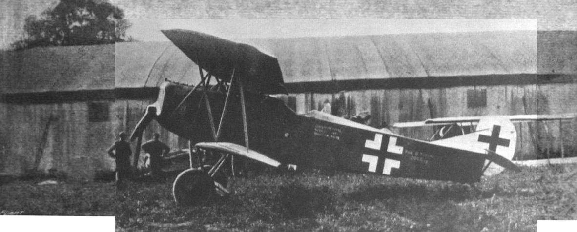
A side view of the Fokker D.VII (D.7) Biplane, showing the curious strut arrangement.
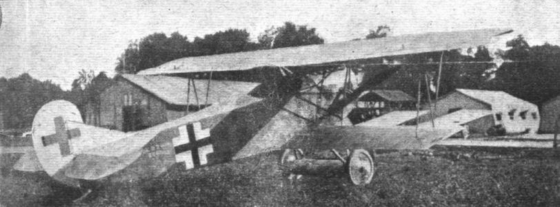
Three-quarter rear view of the Fokker biplane.
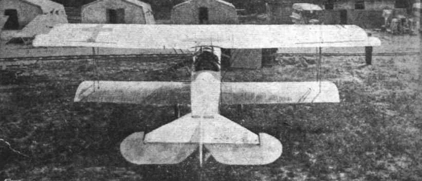
Rear view of the Fokker biplane.

"HANGING ON THE PROP." - The Fokker biplanes are said to be able to assume an attitude similar to that shown in this sketch, and to remain apparently stationary for long periods.

THREE-QUARTER FRONT VIEW OF THE FOKKER BIPLANE, TYPE D VII. - In the machine captured the wings have been somewhat badly damaged, and it has not, therefore, been possible to represent exactly the shape of the wing tips. The upper plane has probably been approximately as shown in the drawing, but of the lower wing sufficient did not remain intact from which to reconstruct the shape of the tip. The unusual strutting of the top plane should be noticed. Inset are some constructional details.

Fig. 15 of the Official Report on the Fokker biplane. Reproduced to show omission of important tubes in the framework. (Compare with "FLIGHT" sketches of same subject.)
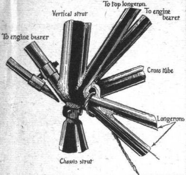
Fig. 2. - A good idea of the extent to which welding is carried in the body of the Fokker biplane can be formed from the accompanying sketch, which shows a joint, or rather a series of joints, where eight different parts meet and are welded together. Needless to say, the making of such a joint would call for the highest skill.
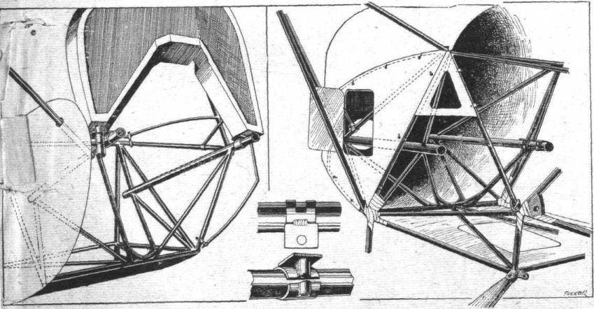
Fig. 3. - Two sketches showing, from different points of view, the engine bearers and their mounting in the Fokker biplane. The inset shows the split collars by means of which the engine is secured to the two longitudinal bearers.
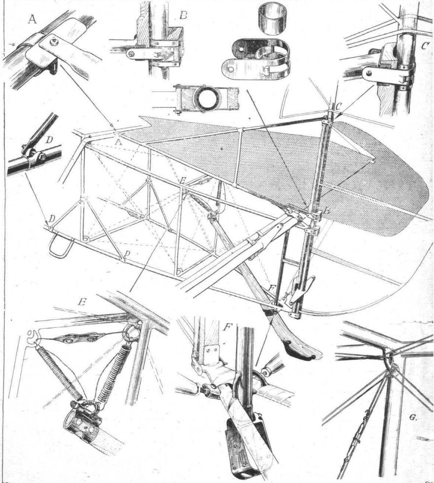
Fig. 4. - Some constructional details of the rear part of the body and of the elevator and rudder of the Fokker biplane. At A is shown the attachment of the vertical fin to the cross tube of the tail plane. At B and C are shown details of the hinges employed for rudder and elevator, and also for the ailerons. The sketch at D shows the split collar by means of which the diagonal tubes that reinforce the body at the point where occur the lifting handles are secured to the lower longeron. At E is shown the springing of the tail skid, and the cable limiting its travel, while at F is illustrated the tail skid attachment to the vertical body strut. The tubular quadrant and wiring of the body is shown at G.
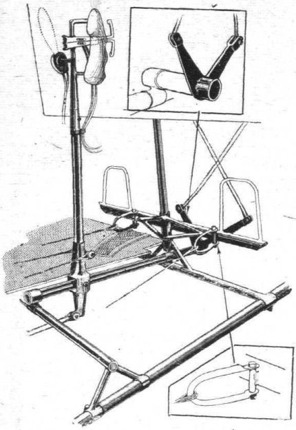
Fig. 5. - Sketch showing controls of Fokker biplane. The insets show the aileron control crank arms and the rudder cable shackles respectively.
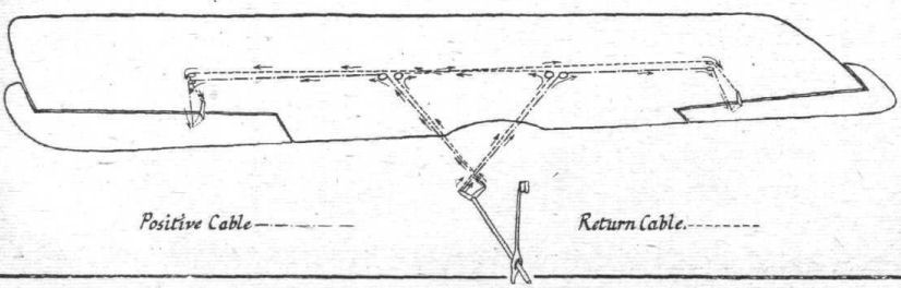
Fig. 6. - Diagram of aileron control system on Fokker biplane.
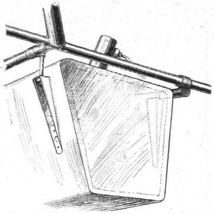
Fig. 7. - The tank of the Fokker biplane is slung by means of brackets and bolts as shown in sketch. There are no bands or other supports for the bottom of the tank.
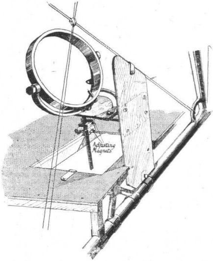
Fig. 8. - The mounting of the compass on the Fokker biplane. Note the adjusting magnets mounted on a square section brass rod under the base plate. These magnets are locked in position and sealed by a lead seal.
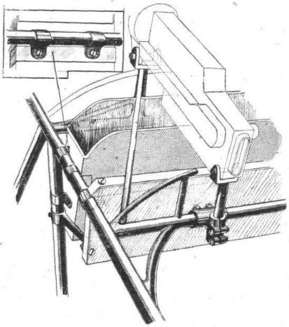
Fig. 9. - Sketch showing mounting of one of the Spandau guns on thel Fokker biplane. Inset, the clips securing the cartridge boxes to the fuselage.
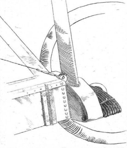
Fig. 10. - The lower ends of the chassis struts of the Fokker biplane are welded to sheet-steel boxes, which carry the shock absorbers, and to which is also attached (by rivets) the aluminium box surrounding the axle.

Fig. 11. - Four typical sections of the wings of the Fokker biplane.
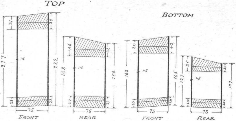
Fig. 12. - Maximum cross sections of the four main spars of the Fokker biplane.
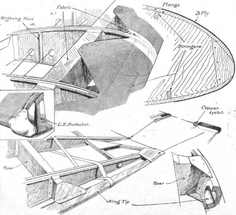
Fig. 13. - Some details of the wing construction on the Fokker biplane.

Fig. 14. - Some details of the spar attachments and aileron pulleys of the Fokker biplane.
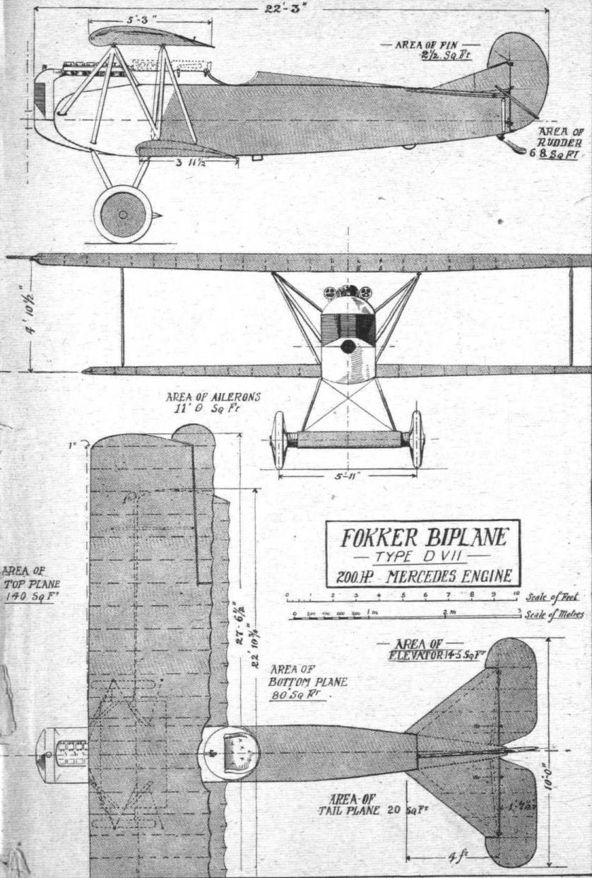
THE FOKKER BIPLANE, TYPE D VII. - Plan, side and front elevations to scale.
Flight, March 14, 1918.
THE FOKKER TRIPLANE.
[The collection of captured enemy aeroplanes at the Enemy Aircraft View Rooms is constantly increasing, and every week brings something interesting of which we should like to inform our readers. It is not, however, possible to do justice to each new arrival before the next one follows, so rapidly do the numbers increase. As we have only available in our columns a limited amount of space which can be devoted to this particular subject, we are faced with the problem of either curtailing the matter of the articles or else perforce defer much that is of interest until space permits publication. A case in point is the Fokker triplane which has just arrived at the View Rooms. We are naturally anxious to place particulars of this interesting machine before our readers as quickly as possible, but at the same time, having far from finished our detailed description of the Albatros Fighter, we should like to complete this before turning our attention to other machines, however interesting. We, therefore, decided this week to somewhat, curtail the description of the Albatros, in order to be able to give just a brief outline of the features of the Fokker triplane. In so doing we regret having had to reduce the instalment dealing with the Albatros to less than it would otherwise have been, but trust that we have made up for this by being the first journal in the world, we believe, to publish illustrations of the Fokker triplane. To the authorities who have courteously given us every facility for dealing with this interesting machine, our readers no less than we ourselves are indebted for the following information.-ED.]
IT has been one of the features of the development of German aeroplanes during the war that, up till comparatively recently their performance has been obtained by a constant increase in engine power rather than by highly efficient aerodynamical design. Such refinements as stream-lined cables, and "spinners" over the propeller boss were not in the past a characteristic feature of German aeroplanes. As, however, the demands for better and still better performance grew, the Germans were obliged to pay more attention to such details, and such machines as the Albatros chaser, with its stream-line semi-monocoque body, was one of the manifestations of this attempt at increased efficiency. The Fokker triplane marks a further step in the battle against that enemy of efficiency, Kx, once expressed by Mr. A. E. Berriman, we believe, as the price paid for the lift. In the Fokker triplane this price has been reduced to what would appear to be an irreducible minimum. So far has the designer gone in his reduction of head resistance as to eliminate all trace of external lift bracing. The Fokker triplane can, therefore, be said to be of the "wireless" type; more truly so than is the case with, for instance, the Curtiss "wireless" in which, although no wires are employed, the struts sloping out from the landing wheels to the lower plane perform the function of lift wires.
No such struts are fitted on the Fokker triplane, the internal construction of the wings being designed to provide all the strength without any external aid of any kind. The interplane struts, which are really ties rather than struts, might conceivably have been omitted altogether, and so far as one is able to judge, their only function is to help to distribute the load more evenly between the three wings. It is well known that in a biplane the upper wing carries about four-sevenths of the total load (when the wings are of equal section, span, and chord) and the lower wing about three-sevenths. In a triplane much the same distribution is found, with the exception that the middle and lower wing each take a share (not equal) of the three-sevenths of the total load.
In the Fokker triplane the upper wing is of larger span than the middle wing, which in turn is of slightly greater span than the lower wing. In consequence, as the three wings appear to be all of the same section, the upper wing must carry more than four-sevenths of the total load. In order to provide a better load distribution, the middle and lower wings are made to carry their share of the load on the top plane by connecting them to this via thin high fineness ratio struts, which are in reality ties as they are working in tension. This explains why the struts are so extremely thin (about 1/2 in.) and the moment of inertia of the strut section would be so small that the struts would buckle under a very small load if subject to compression.
The fact that no lift bracing is employed naturally necessitates wing spars of considerable depth if the spar weight is to be kept reasonable low, and in the Fokker triplane this has been attained by making the wing section very thick in proportion to the chord. As a matter of fact the section is a far greater percentage of the chord than any we have ever seen on a modern aeroplane. For the time being we cannot go into details, this must be postponed until we do a full description of the Fokker, but roughly we should say that the maximum camber is in the neighbourhood of one-eighth of the chord.
The two wing spars are placed very close together, and are enclosed in a box of three-ply wood. The function of this box is two-fold, it increases the strength of the spars for taking bending and at the same time acts as internal drift bracing. At the moment of writing we are not able to say whether or not any other drift bracing is employed, but we are inclined to think that this function is performed solely by the ply-wood box.
The upper wing, which is in one piece, runs right across, and is supported on struts sloping outwards as in the Sopwiths. The other two wings each have a centre section rigidly attached to the body, the middle one resting on the top longerons and the bottom one running underneath the lower longerons, an aluminium shield streamlining the normal surface presented by the deep flat sides of this spar.
From the illustrations it will be seen that the gap is unusually small, being very considerably less than the chord. The inefficiency thus caused is partly made up for by staggering the wings but even so one would imagine the machine to be somewhat inefficient. The interference owing to too close spacing of the wings chiefly affects the lift co-efficient, and as the machine is probably very lightly loaded compared with the majority of German machines - it is possible that the landing speed is not excessive.
Strictly speaking the Fokker is not a triplane. It would be more correct to term it a three-and-a-half plane, as the wheel axle is enclosed in a casing of ply-wood which has a section somewhat similar to that of the wings. Experiments have shown that floats of such a section as to have a deeply cambered top surface may be made to support their own weight during flight. In the case of the Fokker triplane it appears probable that this ply-wood casing around the wheel axle carries a not inconsiderable load during flight. Its section appears capable of supporting a fair load per sq. ft. of area, and its inefficiency due to low aspect ratio is probably less than one would expect in a plane of an aspect ratio of about two, on account of the proximity of the covered-in wheels to the tips, the effect of which must be to stop end losses to a considerable extent.
As regards the body of the Fokker triplane this is constructionally very similar to that of the Fokker monoplanes. Longerons as well as struts and cross members are in the form of steel tubes, and are joined together by welding. The internal bracing of the body is peculiar in that the bracing wires are in appearance in duplicate, although they are not so in effect.
The arrangement, to which we shall revert again when dealing with the Fokker in detail, does not appear to possess any other advantage than that in each bay only half the number of loops have to be made in the wires.
The tail plane, as well as the elevators and rudder, is made of steel, and is of a symmetrical section, much thinner than that of the Albatros, but otherwise similar to it in that no external bracing is employed. While this is quite satisfactory in the Albatros on account of the thick tail plane spars employed, it appears wholly inadequate in the Fokker, as the plane is very thin, and since, moreover, the trailing edge of the tail plane is a steel tube, which section, as is well known, is not a good one for a laterally loaded beam, owing to the fact that much of the material is massed around close to the neutral axis where it is not taking very much of the load.
As exhibited at the Enemy Aircraft View Rooms the Fokker is not complete inasmuch as the engine has been removed. The cowling shows without a doubt that the engine must have been a rotary, and the mounting is of the type usually employed for rotary engines, i.e., a main engine plate bolted to the nose of the body, and a pyramid of steel tubes, supporting at its apex the rear end of the crank-shaft. A sheet of aluminium is placed immediately in front of the engine plate. The manner of cowling in the engine will be apparent from our illustrations, and does not present anything of particular interest, following as it does conventional practice.
Although they are not in place in the machine as exhibited, it is evident from the aluminium casings for the cartridge belts that two synchronised machine guns have been fitted, one on each side above the fuselage. The usual triggers, operating the guns through Bowden cables, are mounted on the control lever, which latter is of the usual type.
Painted on the side of the fuselage are the following data relating to the weight of the machine: Weight empty, 376 kg., useful load, 195 kg., total weight, 571 kg. (about 1,250 lb.)
With these brief particulars we must leave the Fokker triplane for the time being, but later on we hope to return to it again, and to be able to give illustrations of some of its more important constructional details.
Flight, May 2, 1918.
THE FOKKER TRIPLANE.
[Just as we have completed the preparation of our data for an illustrated description of the Fokker triplane which is now exhibited at the Enemy Aircraft View Rooms, we receive from the Technical Department of the Aircraft Production Department of the Ministry of Munitions an official report on this machine. The report is somewhat brief, possibly owing to the fact that the design is now said to have been discontinued. That the German "Ace" Freiherr von Richthofen should have chosen for his favourite mount a Fokker triplane after this machine had been turned down by the authorities need not cause any surprise, and only goes to prove that this is not the only country in which opinions may differ as to what is or is not a safe and suitable design. We do not mean to infer that the machine on which the famous German pilot met his death was necessarily identical with the one here under review, which was built during the latter part of last year, and of which we have already published a brief description in our issue of March 14th. As a matter of fact the probabilities are that there were considerable differences. But thereby hangs a tale, which is recorded elsewhere in this issue.
To return to the official report on the Fokker triplane. It is apparent, from a paragraph on the cover, that the authorities feel called upon to apologise for the brevity of the report, and it is stated that the report is issued for information, "though it is felt that the machine exhibits few instructive features." This is a policy with which we cannot in any way agree. It may happen - and, we think, very frequently does happen - that a thing which has proved a failure is very often far more instructive than one which was a success. After all there is always a tendency for anything successful to engender imitation, whereas failure tends to stimulate original thought which may in time lead to the production of something really good. Moreover, to come down to a specific case, although this particular design may have proved itself bad, who will venture to say that it may not contain the germ of an idea which someone may be clever enough to grasp and to turn to good account? We therefore propose to deal with this machine in our own particular manner and as fully as seems necessary, hoping that it will prove as interesting and instructive as our numerous correspondents have been good enough to tell us our previous articles of this nature have been. - ED.]
THE Fokker triplane is chiefly remarkable on account of its total absence of external lift bracing, but offers, on closer examination, a number of constructional details, some good, some indifferent, and some frankly bad, but always interesting, which are well worth a careful study. It appears that, generally speaking, German designers either try to do without metal altogether, or else go to the other extreme and use it exclusively. In the latter ease it will often be found that welding is very extensively employed, even on jobs for which it is least suitable, as, for instance, fittings working in tension. This gives one the impression that German designers are divided into two schools. One, which does not trust welded joints and therefore attempts to do without metal as far as possible; and the other, being "all out for metal," which appears to have a childlike faith in the skill of their welders and uses welded joints in and out of place.
The Fokker triplane indicates that its designer does not belong exclusively to either school, but is influenced by both. That is to say, he seems to have incorporated in his design the extremes of both schools. Where he uses metal he uses it exclusively and throws in a profundity of welded joints, and where wood takes his fancy he goes to considerable trouble to circumvent the difficulties attending wood construction, simply to be able to use wood where in many cases metal would have offered a much simpler solution. The explanation may be that den Heer Fokker commenced his aeronautical career as a disciple of the all-metal school - his old monoplane was, it may be remembered, built almost exclusively of steel - but is beginning to lean towards the all-wood school, whether by inclination or because of the conditions prevailing at present one cannot say. It is in the wing structure that the wood construction predominates, while the body is built entirely of steel.
In conformity with his past preferences, Fokker has employed steel tubing throughout in the construction of the fuselage of his triplane. The longerons, struts and cross members are all made of this material, the diameter of the tubing employed varying somewhat locally according to the different stresses. Probably the gauge of the tubes varies also, but this we have not been able to verify, as none of the tubular members are cut through on the machine exhibited.
The general arrangement of the body of the Fokker triplane is shown in Fig. 1 in plan and side elevation. It will be noticed that the lower longerons <...> a rather abrupt upward bend just behind <...>where the spar of the lower wing is attac<...> that secondary longerons are employed for <...> the continuity of the curve from this po<...> engine plate. At the rear the top lon<...> dropped a matter of a couple of inches to acci<...> the tail plane, much after the manner of the <...> Deperdussin monoplanes.
In section the main body is rectangular, while the front portion carries in addition superstructures on top and sides, which carry the circular section near the engine gradually into the flat sides and top of the rear part. As regards the detail construction, struts and cross members are butt-welded to the tubular longerons. This does not impress one as a particularly good arrangement, since the effect of vibration on the welded joints may easily become serious.
If the method of joining the members of the fuselage structure is open to criticism, the arrange<...> the bracing system is even more so. As briefly <...> out in our previous notes on the Fokker <...> the bracing wires of the body have the <...> of being in duplicate, but are in effect <...> they are merely looped around the tubular <...> forming the standard terminal at the <...> of struts and longerons. The details of this arrangement will be more easily understood from reference to Fig. 2. It will be seen that the only advantage gained by having the bracing wires so arranged is a saving of two loops and two ferrules in each wire. From the point of view of rapid production the gain thus effected cannot be considerable, while the saving in weight could only amount to a very few pounds in the whole body. Against this we have the weakness due to the fact that if one part of the wire breaks - whether the part with the wire strainer or the plain part matters little - the whole strength is gone, since the wire would, as soon as subjected to a tension of a few pounds, pull around the tubular anchorage. Another point suggests itself when examining the body bracing. When tuned up the tension in the wire is probably uneven, the plain part of each wire being tensioned to a less extent than the length incorporating the strainer, owing to friction between the loop of the wire and the terminal tubular quadrant. In certain instances this wire attachment has been varied to suit local requirements, but everywhere where other considerations do not have to be taken into account the anchorage and wiring is as shown in Fig. 2.
(To be continued.)
Flight, May 9, 1918.
THE FOKKER TRIPLANE.
(Continued from page 476.)
FROM Fig. 1 (see page 474 in last week's issue) it will be seen that in the front portion of the body the strutting is so arranged that the usual diagonal wire bracing becomes superfluous, the tubular struts being arranged in a series of triangles which by themselves render the structure rigid. As a consequence the anchorage tubes differ somewhat from those employed in the rear part of the body. Generally speaking they take the form of straight tubes welded over the angle formed by adjacent struts, and instead of lying in a transverse plane, as do the rear ones, they are in the same plane as the sides of the body. As for the attachment of the struts themselves to the longerons, this is practically the same as that employed in the rear part of the body, i.e., by butt-welded joints. Here and there one finds additional fittings for receiving chassis struts or wing attachment, but these are supplementary rather than departures from the universally adopted scheme.
As we have already mentioned, the rectangular section of the main body of the Fokker triplane is partly streamlined in front by superstructures secured to the sides and top of the body. These fairings take the form of triangular sheets of thin three-ply wood, attached to the upright struts of the body by means of short distance pieces of spruce and by aluminium clips, as shown in Fig. 3. The middle spruce rail of these fairings, it will be seen, runs back slightly farther than the top and bottom ones, and its rear end is not attached to the body except in so far as it rests against one of the body struts. Apparently the tension of the fabric body covering is relied upon to keep it in place. Reference will be made to the armament of the Fokker triplane later, but while dealing with Fig. 3, we would call attention to the mountings for the two machine guns, which this sketch shows. Each gun, it will be seen, is supported on two fork end brackets, the front ones of which are rigidly attached to one of the top cross struts of the body, while the rear ones are so designed as to allow of aligning the guns. Each of these supports is in the form of a fork end mounted on the end of a tubular pillar, which is in turn held in position at its lower end by a split collar on the transverse body strut. This collar may be shifted laterally along the horizontal strut and locked in position at any desired point, thus providing for the lateral alignment of the rear gun support. The vertical adjustment is effected by the vertical displacement of the pillar carrying the fork end, which is locked in position by the vertical part of the split collar or clip.
Having dealt with the general construction of the body, we next come to consider its internal fitting up. The pilot's cockpit, which appears to be of somewhat less generous proportions than those usually found on German machines, gives a somewhat ascetic impression contrasted with the somehow cosy and comfortable cockpits of other machines of German origin. This may be partly accounted for by the fact that the body structure is steel tubing, but no doubt the chief reason is to be found in the inadequate upholstering of the seat, which is of the aluminium "bucket" type. The covering is some sort of pegamoid stuff, and looks on the whole "cheap and nasty." This appearance, by the way, is not confined to the seat only, but is noticeable throughout the machine. To finish, as we understand it, there is no pretence, and the workmanship, which is not, of course, by any means the same thing, although the two are frequently confused, even by those who ought to know better, is not by any means beyond reproach. On the whole we are inclined to think that the unfavourable impression left by an inspection of the Fokker triplane is due to bad finish and workmanship quite as much as if not more than to poor design. The pilot's seat is so mounted as to be capable of being easily adjusted in height. It is supported on a framework of steel tubes, as shown in Fig. 4. This framework is attached to the upright body struts by tour sliding collars, the upper two of which are split and fitted with a locking bolt, as shown in the inset, Fig. 4. This locking bolt is rather long, so as to make more accessible the wing nut which tightens up the split collar. The necessary adjustment is easily made from inside the body, both wing nuts being easily reached from the seat.
The controls, which are shown in the central sketch of Fig. 5, consist of a vertical tubular control lever mounted on a longitudinal rocking shaft, and of a tubular foot bar for the rudder. The details of the control gear will be readily followed in the sketch. A large collar, to the top and bottom of which are welded the anchorages of the elevator cables, is pivoted to the rocking shaft by a horizontal bolt and is free to be moved through a considerable angle in a longitudinal plane owing to being so much larger in diameter than the shaft. The latter, which is carried in bearings formed by clips gripping the lower cross struts, is free to oscillate laterally, and carries near its forward end two cranks placed at an angle and staggered in relation to one another. From these cranks cables pass over pulleys on the top spar to the ailerons.
At its upper end the control column carries a double-handled grip and the triggers for the machine guns, as well as the cut-out switch for the engine. The handle on the left is not, however, fixed in the usual manner, but serves, by being pivotted, for operating the engine throttle, via Bowden cables. Two triggers are provided by means of which either of the two machine guns can be brought into gear. On the front of the lever will be seen a bent steel rod which, on being pulled back, puts both machine guns into gear, thus firing them simultaneously. The connection is as usual by Bowden cables, and the interrupter gear is driven by a pinion engaging with the gear wheel that meshes with the magneto and oil pump drives. The gun triggers and other details of the control handle are shown in the inset in the bottom right-hand corner of Fig. 5.
The foot bar for the rudder is in the form of a steel tube pivotted around a vertical tube resting at its lower end on a bracket under the floor boards and secured at its upper, after being bent back slightly, to the deck of the body. The pilot's feet rest in loops of thin tubing welded to the main foot bar, while the rudder cables are attached to the bar by two stirrups, the bolts for which have their bearing in a short length of tubing welded to the front of the foot bar.
Throughout the body of the Fokker triplane extensive use is made of split collars similar to that shown in the upper right-hand corner of Fig. 5. Extra stiffness of the flange is provided by stamping this out to the shape of a shallow cup in which are the holes for the bolt locking the collar in position. Where, as frequently happens owing to the tubular construction, two of these collars have to be placed at right angles to one another, they are joined together by welding. This is the case, for instance, with the guides for the control cables running to the tail. These guides are shown in the bottom left-hand corner of Fig. 5, while yet another form of the clip, slightly different in detail but similar in principle, is shown on the left. This sketch represents the clip and guide tube for the aileron cable on its way from the cranks in the body to the pulleys on the spar of the top plane.
As shown at the Enemy Aircraft View Rooms, the Fokker triplane did not show any signs of having been fitted with an instrument board, and of such instruments as revs, counter, altimeter, air speed indicators and fuel indicators there was no trace. On the right-hand side of the pilot the cardan support for the compass was still in place, and the bracket supporting it is of the form shown in the sketch, Fig. 5. On the left was a quadrant and shaft, evidently for controlling the fuel and oil. One large tank just behind the engine support is divided by a longitudinal bulkhead, the right-hand compartment containing the oil and that on the left the petrol. According to the official report on the Fokker triplane, the capacities of the two tanks are 4 gallons and 16 gallons respectively, or sufficient for a flight of 2 1/2 hours' duration.
(To be continued.)
Flight, May 16, 1918.
THE FOKKER TRIPLANE.
(Continued from page 512.)
THE engine mounting on the Fokker triplane has already been briefly indicated in our side elevation and plan of the fuselage (see page 474 of our May 2nd issue). Fig. 6 is a perspective sketch further illustrating the general arrangement of the engine support. The main engine plate, which is in the form of a ring, is supported on a structure of steel tubes arranged in the shape of a four-pointed star. The rear engine support, on the other hand, is mounted on a pyramid of steel tubes, running to the same four points, i.e. the corners of the fuselage, as the four points of the star. The attachment to the body is shown in detail in Fig. 7. The apex of the three-legged pyramid formed by the two front bearer tubes and single rear bearer tube is welded to a longitudinal horizontal lug. This lug is in turn supported by a long bolt passing through a hole in a triangular corner plate welded to the vertical and transverse body struts. Thus by undoing the four bolts the whole engine mounting may be removed bodily. This is, of course, an advantage, but structurally the arrangement can only be considered very weak. Ultimately, it will be seen, a welded joint - that of the triangular corner plate to body struts - or, more correctly speaking, four of them, is relied upon to support the engine. This can scarcely be considered anything except very bad practice. In conformity with usual practice there is an aluminium capping plate covering the front engine bearer. This plate is held in place by the four bolts carrying the engine mounting, the bolts passing through and being locked on the front face of the aluminium plate, where they are easily accessible.
The under-carriage of the Fokker triplane is of the now usually employed Vee type, but it differs in several respects from standard practice. Thus the fairing round the axle is of much larger dimensions than those usually obtaining, so much so that it constitutes in reality a supporting surface of an area that can by no means be considered negligible. In the official report on the Fokker triplane, this fairing is represented as being of symmetrical cross section. We confess that we are not quite decided as to whether or not this is correct. In the specimen shown at the Enemy Aircraft View Rooms, the fairing is very much damaged, and it is almost impossible to ascertain definitely what was the exact cross section, but from the fragments left intact we are inclined to think that the three-ply casing was not a symmetrical stream-line section, but rather a section approaching somewhat to that of the main planes, with the exception, possibly, that, it had a flat under-surface and a cambered top. However, this is somewhat in the nature of a conjecture, and we merely express it as our personal opinion. That the extra lift obtainable by making this member a lifting surface would be worth considering appears probable, since the inefficiency due to low aspect ratio would be to some extent compensated for by the proximity of the flat inner sides of the wheels to the tips of the surface, which would thus act as baffle plates and tend to reduce end losses.
Constructionally, the casing around the axle consists of a covering of three-ply wood, supported on a rectangular section aluminium casing around the axle, and on two circular section aluminium tubes acting as auxiliary spars. The end of the axle casing is a steel box to which are welded the lower ends of the under-carriage struts. From this steel box also project the two tubular stubs to which are anchored the shock absorbers. This arrangement is shown on the right in Fig. 9, while the sketch on the left gives an idea of the general construction of the whole axle casing. The under-carriage is braced laterally by stranded cables in the front bay only.
The struts of the under-carriage are secured to the body by a form of ball and socket joint, the socket being slotted for some distance from its open end. A short pin is passed through an opening in the ball-shaped end of the strut, and is locked by a small split pin. The joint looks extremely weak, and cannot, one imagines, have nearly as high a factor of safety as the strut which it is meant to secure.
While on the subject of the under-carriage reference may be made to the tail skid. This is of wood and pivoted, the attachment being as shown in Fig. 8. The vertical tube supporting the tail skid is welded to the four longerons which at this point converge to within a very short distance of one another. At its upper end the tube secures the rear spar of the tail plane.
Fig. 10 shows the tail plane and rudder. The former, as already pointed out, is brought down to the level of the top longerons, by dropping these for the last few feet slightly below those in the front part of the body. The main framework of the tail plane is in the shape of a trapezoid, three sides of which are formed by steel tubes of large diameter, while the fourth side is a wood beam. Over this framework the ribs are built, the flanges being in the form of small diameter steel tubes. These tubes are welded to thin collars surrounding the converging tubes, thus avoiding the possibility of weakening the larger tubes by heat. The construction of the elevator ribs is similar to that of the tail plane, while the rudder ribs are slightly different, being reinforced by short lengths of tube running zig-zag fashion from one flange to the other. The hinges for the elevator tube are of a very simple form, being in appearance short lengths of channel section metal bent around the tube and fastened by a single bolt to the tail plane spar. These hinges are extensively employed on the Fokker triplane, being used also for the rudder and aileron hinges. The elevator and rudder crank levers are welded direct to their tubes without the intermediary of a collar. Their general shape will be clear from Fig. 10.
(To be continued.)
Flight, May 23, 1918.
THE FOKKER TRIPLANE.
(Continued from page 536.)
WE now come to deal with the most interesting part of the Fokker triplane, the wing structure. It has already been pointed out that the machine is of the "wireless" type, inasmuch as there are no lift wires or landing wires, the only wires employed in the wing structure being the diagonal cross bracing between the centre struts sloping upwards and outwards from the body to the top wing. Aerodynamically this is advantageous from the point of view of low resistance, but structurally it is open to criticism on the score that it is difficult to provide adequate strength in such a structure, and that the only possibility of doing so is to employ a very deep wing section which will allow of using spars of such a section and depth that its moment of inertia is large without its area being excessive. This is precisely what the designer of the Fokker triplane has done. The wing section is one of far greater depth than one is accustomed to find on a modern fast machine, and inside this deep section he has built up a composite spar of somewhat unusual construction. Hitherto the vast majority of aeroplanes of any nationality have had wing spars which were either of the I or of the box section. In the Fokker spar we have neither strictly speaking, since it is certainly not an I section and only a box spar after making certain allowances. Briefly speaking, the principle of the Fokker triplane spar is the following: There are two spars as in the majority of other wings, but placed absurdly close together. Each spar is of the box type inasmuch as it consists of spruce flanges top and bottom, with a web of three-ply on each side. The top and bottom faces of these two spars are then united by a sheet of three-ply covering, them up so as to form in effect two boxes within a box. In this manner there is no need # or at any rate the designer appears to be of that opinion # for any internal wing bracing, this being provided by the top and bottom three-ply covering.
In Fig. 11 are shown some of the constructional details of the Fokker wings. The sketch at the top of the illustration shows the upper starboard wing in general arrangement. The construction is similar in all wings as regards fundamental principles, and only differs in minor details where this is necessitated by local requirements. The outward appearance of the wing spar is shown in the top sketch, and also the manner of attaching the ribs, which are prevented from sliding along the spar by little triangular section blocks of wood tacked to the spars. The sketch in the centre shows the construction of the spar, and one of the longitudinal partition, which occur at certain intervals along the spar. These partitions are made up of four strips of spruce, halved together and glued. The ribs have spruce flanges and very thin webs of three-ply wood, approximately 1 mm. thick.
The leading edge is formed by a long strip of three-ply, wrapped around the nose of the ribs, and cut out in triangular shapes, the apices of which are secured to the top of the spar.
As shown in the scale drawings of the Fokker triplane (published in our issue of May 2nd), the upper wing is supported from the body on two inverted Vees of steel tubing, sloping outward at a considerable angle. Details of the attachment of the apex of the Vee to the top spar are shown in the two sketches at the bottom of Fig. 11. Two channel section plates are secured to front and rear faces respectively of the spar, by two horizontal bolts passing through the spar. To the bottom end of each plate is welded a small lug, internally threaded, into which is screwed a vertical bolt, the other end of which passes through a lug on the strut structure and is secured in position by locknuts. It will be seen that by suitably adjusting the bolts securing the spar, the angle of incidence may be slightly varied. To the left of the strut attachment will be seen the pulleys for the wing flap cables, which run from this point to the cranks of the rocking-shaft in the body.
Mention has already been made of the fact that the interplane struts are extremely thin, and are in effect ties rather than struts. They are made of wood, and the attachment to the spars is shown in the remaining sketches of Fig. 11. That on the left shows the attachment to the lower spar, and the sketch on the right indicates how the same method, with slight modifications, is employed for securing the inter-plane struts to the middle spar. A shoe of thin sheet steel is wrapped around the end of the strut, and through it a long tubular bolt is passed, which also runs through the holes in the channel section plates on the sides of the spar. The principle is really the same as that for attaching the body struts to the spar. In the latter, however, the channel plate has its upper end bent over the edge of the spar, presumably to assist in relieving the bolts passing through the spar of the shearing stress.
In Fig. 12 are shown some of the details of the lower wing near the tip. On the right will be seen a sketch illustrating the peculiar construction of the extreme wing tip. This is formed by placing an ordinary rib horizontally, attaching it to the last main rib by triangular brackets of wood. The remaining sketches of Fig. 12 show the details of the wing tip skid. From the sketch on the left it will be seen that the skid is so close up against the lower surface of the wing that the machine would have to cant over at an alarming angle before the skid would come into play, and it is difficult to see how the skid could be of any great practical use. Its attachments are shown in the detail sketches, that on the left indicating how the skid is pivoted, while that on the right shows how the free end of the skid is secured. Small bolts pass through these fittings and are locked on the inside of the spar in the manner indicated in the small sketch.
The attachment to the body of the lower and middle wing is shown in the sketches of Fig. 13. That on the left, illustrates the bottom plane attachment. It may be remembered that the main lower body rails were passed over the bottom spar, auxiliary rails being provided for maintaining the continuity of the curve underneath the spar. This is indicated in the sketch on the left. The attachment itself is exactly similar in principle to that of the top spar to the body struts. Again provision has been made for adjusting the angle of incidence. The middle spar attachment, shown on the right, is to all intents and purposes the same reversed. In this connection it should be remembered that the spars run right across from side to side in one piece. This has an important bearing on the wing spar stresses, with which we hope to deal next week.
(To be continued.)
Flight, May 30, 1918.
THE FOKKER TRIPLANE.
(Continued from page 569.)
Among the interesting features of the Fokker mention must be made of the wing section, which alone has made the "wireless" arrangement possible. Although wing sections are nowadays probably thicker, on an average, than they were some years ago, due to the more insistent demands for strength and light weight, there are few machines if any, that can compare in this respect with the Fokker triplane. The maximum depth, which occurs in the neighbourhood of the front part of the composite spar, is no less than 4.95 ins, or practically 5 ins, and this for a chord of only 1 metre (about 3 ft. 3 1/4 ins.). A scale drawing of the wing section is given in Fig. 14, from which the depth at various points along the chord can be found. The web of the rib, which is made of thin three-ply, is unusual in that it is not cut where it abuts against the spar faces, as is general practice, but is continuous from leading to trailing edge. This has been made possible by the fact that the composite spar is of a rectangular section of a maximum depth determined by the rib depth at the rear edge of the spar, which leaves a small space between the top and bottom faces of the spar and the rib flanges. Whether or not this provides any very great increase in the strength of the rib is perhaps doubtful, but keeping the spar of rectangular section would certainly appear to have advantages from the point of view of construction, as all the four strips of the spar may thus be kept of rectangular section instead of, as they would otherwise have to be, being shaped to fit the slopes of upper and lower faces of the spar. As regards the spar itself, reference has already been made in a previous instalment to its general construction. Fig. 14 gives the dimensions of the various component parts of the spar. These dimensions apply to the inner portion of the spar, near the root, and to this point only, as the dimensions vary throughout the length of the spar, an attempt having apparently been made to proportion, to a certain extent, the strength of the spar to the load at any point. As regards the four spruce strips of the spar, these are tapered in plan view, their width from front to back changing from about 2 ins. at the root to about 3/8 in. at the tip. The depth of the flanges, on the other hand, remains constant. The ply-wood covering or box spar has also been varied, the outer half being covered with one layer of three-ply, while the inner portion has an extra thickness of three-ply, making in reality a flange of six-ply wood.
As the wings are to be regarded as cantilevers, the object of this construction is evidently to reduce weight to a minimum by reducing the size of the spar where the loading permits of doing so, that is to say more or less gradually from the root towards the tip.
The opinion has been advanced that the Fokker triplane construction is extremely weak. So, on the face of it, would it appear to be, but as the machines have repeatedly been mentioned as doing good work, (although this may possibly refer to a later type) and since the arrangement is very unusual, we have thought it might be of interest to examine whether or not the Fokker system is as weak as one is apt to imagine at first sight. A reference to the front elevation of the machine (published in our issue of May 2nd) shows that the span of the upper wing is greater than that of the middle wing, which is in turn of greater span than the bottom one. From tests carried out by Mr. J. C. Hunsaker at the Massachusetts Institute of Technology (the results of which were published in "FLIGHT" for November 23rd, 1916), on triplane combinations of wing sections of the R.A.F. 6 type, it appears that for a triplane combination in which the three wings are of equal span and chord and not staggered, the triplane ky is .0004, while the value of upper, middle and lower wing ky is respectively .0006, .0002, and .0004. In other words, the ky of the lower wing is practically the same as that of the triplane combination, while that of the upper wing is very much greater and that of the middle wing considerably smaller. In the case of the Fokker allowance should be made for stagger and for the fact that the three wings are of unequal span, but as we have no data to go on, and since, moreover, any difference in interference caused by the unequal spans will probably not be sufficiently great to seriously affect our purpose of making an approximate estimate of the spar stresses, we shall disregard the difference due to unequal spans and take the figures as they stand. The weight of the Fokker triplane is given as about 1,260 lbs. The area of the top wing is about 83 sq. ft., that of the middle wing 54.5 sq. ft., and that of the bottom wing 51.9 sq. ft. Assuming the lift distribution to be the same as that found by Hunsaker, we obtain a lift of 9.21 lbs./sq. ft. of the upper wing, 3.09 lbs./sq. ft. of the middle wing, and 6.14 lbs./sq. ft. of the lower wing - the average loading being that of the bottom wing, or 6.14 lbs. per sq. ft.
Fundamentally the Fokker wing bracing is such that each wing may be considered a cantilever beam, and they would be truly so except for the struts, or rather ties, connecting them. These ties, however, only serve to force the middle and lower wings, which are more lightly loaded on account of the load distribution and also by reason of their shorter span, and which have the same spar section as the upper wing, to share some of the load on the top wing. If, therefore, we disregard the assistance given the top wing by the other two, and if we further assume a uniform distribution along the span of the wing instead of taking into account that the portion of a wing near the tip is always more lightly loaded than the inner part, we can hardly be accused of being unduly optimistic with regard to the Fokker wing system.
The load carried by the upper wing in the Fokker triplane is 9.21 x 83 = 764.43 lbs., say 770 lbs. The central span in about 5 ft. 2 ins., leaving on each side a cantilever of about 8 ft. 4 ins. or 100 ins. Assuming a uniform loading along the span, and remembering that the bending moment on the centre section wl^2/8 while that on the cantilever portions is wl^2/2, it will be seen that compared with the bending moment on the cantilever, the bending moment on the centre span is negligible. As a matter of fact it is only about 1,400 lb. in. The loading per inch run is 2.9 lbs., and the bending moment on the cantilever is wl^2/2 = 2.9 x 100^2 / 2 = 14,500 lb. in.
From Fig. 14 it will be seen that the dimensions of the four spruce flanges of the spar are 2 1/8 ins. by 5/8 in., so that the area of the four spruce sections is 5.36 sq. ins. The depth of the spar is 4 ins., and the section modulus Z may be taken with sufficient accuracy as being equal to area of flanges multiplied by half the depth of the spar, or 5.36 x 2 = 10.72. Assuming the strength of spruce as being 8,500 lbs. sq. in. the moment of resistance of the spar flanges will be: 8,500 x 10.72 = 91,120 lb. in.
Treating the box spar formed by the ply-wood separately, the section modulus Z = (1 / (6 x 4) ) x (7.88 x 64 - 7.38 x 52) =5.02, and the moment of resistance of the ply-wood box, assuming the strength of the ply-wood to be the same as that of spruce, will be: 8,500 x 5.02 = 42,670 lb. in.
The total moment of resistance of the spar will then be 91,120 + 42,670 = 133,790 lb. in. Without knowing the travel of the centre of pressure on the Fokker wing section it may reasonably be assumed to be such that it may coincide with one flange of the composite spar, and to be on the safe side we shall take it that when the c.p. is in this position the strength of the composite spar is reduced to half. The moment of resistance is then 66,895 lb. in., and as the maximum bending moment was found to be 14,500 lb. in., the factor of safety is apparently about 4.5. This is without regard to the fact that this load is greatly reduced by the interplane struts, by how much is rather outside the scope of a descriptive article like the present to determine, but to which we may refer on a future occasion. One can, therefore, only arrive at the conclusion that the Fokker wing bracing system need not be inherently weak, although detailed calculations based upon more exhaustive data than we have available would possibly indicate that the spar weight compares somewhat unfavourably with, that of spars of more usual type and arrangement.
As regards the aerodynamical qualities of the Fokker wing section, it is difficult to express an opinion. Generally speaking machines of the Fokker class have been found most efficient for their purpose when fitted with wings of a section giving a rather low ky, but a good L/D ratio, whereas the deeply cambered section, having a very high value of the lift coefficient, has generally a smaller L/D value. The opinion has been expressed that the Fokker wing section resembled that tested by Dr. Schukowsky. In order to ascertain if this were the case we have plotted the two sections shown in Fig. 15. Some difficulty was experienced owing to the fact that the dimensions of the Schukowsky aerofoil given in A. W. Judge's book "Properties of Aerofoils," did not, when plotted out, give a fair curve. However, by comparison with the small illustration in above book, we were able to plot out an approximately correct section of the Schukowsky aerofoil. In Fig. 15 the Schukowsky section is shown in dotted lines. It will be seen that except for the trailing portion of the upper surface there is little or no resemblance between the two sections. It would therefore be futile to attempt to predict, from a knowledge of the Schukowsky coefficients, the performance of the Fokker wing section. One can only point out that it appears probable that the section has been chosen primarily with a view to accommodate the very deep spars, and that it has been found in practice to give reasonably good results - probably especially at a considerable altitude. It would appear that the section is suited for good climb rather than for great speed, and according to German claims, the climb of the Fokker is what they like to boast of rather than the speed. Whether or not the latter is made up for by an ability on the part of the Fokker triplane to climb rapidly and to a great altitude, hence to dive on to its victim from above, we cannot say. It is possible that it may be. Taking it all around, it is doubtful if the gain in reduction of head resistance due to absence of external lift wiring is sufficient to make up for the necessarily heavier wing construction. Of strength, it would appear from the foregoing that one can only conclude that this can be provided to an adequate degree.
The following dimensions and data are taken from the official report on the Fokker triplane :-
Identification marks. - R.F.C. No. G. 125; Maker No. 1856; Military No. FOK. D.R.I. 144/17; date of construction, 20.10.17.
Weights (as stencilled on machine). - Weight, empty, 376 kg. (829 lbs.); permissible load (including fuel), 195 kg. (430 lbs.); total weight, 571 kg. (1,259 lbs.).
Weight of engine. - 334 lbs., including hub, magneto, oil pump and carburettor. (NOTE.-Weight of 110 h.p. Le Rhone is 330 lbs.)
Tank capacity. - Petrol, 16 gallons (approximate) ; oil, 4 gallons (approximate) ; approximate duration, 2 1/2 hours at 10,000 ft.
From the above it is possible to construct the following approximate weight analysis : Fuel, oil and tank, 170 lbs. (allowing tank, 18 lbs.); crew, 180 lbs.; military load, 98 lbs.; engine and propeller, 358 lbs. (allowing propeller, 24 lbs.); structure, 453 lbs. (including engine bearers and instruments); structure percentage, 36; surface of main planes, 205 sq. ft. (approximately); estimated B.H.P. (by analogy with 110 h.p. Le Rhone), 113; lbs. per square foot, 6.14; lbs. per B.H.P., 11.15.
THE FOKKER TRIPLANE.
[The collection of captured enemy aeroplanes at the Enemy Aircraft View Rooms is constantly increasing, and every week brings something interesting of which we should like to inform our readers. It is not, however, possible to do justice to each new arrival before the next one follows, so rapidly do the numbers increase. As we have only available in our columns a limited amount of space which can be devoted to this particular subject, we are faced with the problem of either curtailing the matter of the articles or else perforce defer much that is of interest until space permits publication. A case in point is the Fokker triplane which has just arrived at the View Rooms. We are naturally anxious to place particulars of this interesting machine before our readers as quickly as possible, but at the same time, having far from finished our detailed description of the Albatros Fighter, we should like to complete this before turning our attention to other machines, however interesting. We, therefore, decided this week to somewhat, curtail the description of the Albatros, in order to be able to give just a brief outline of the features of the Fokker triplane. In so doing we regret having had to reduce the instalment dealing with the Albatros to less than it would otherwise have been, but trust that we have made up for this by being the first journal in the world, we believe, to publish illustrations of the Fokker triplane. To the authorities who have courteously given us every facility for dealing with this interesting machine, our readers no less than we ourselves are indebted for the following information.-ED.]
IT has been one of the features of the development of German aeroplanes during the war that, up till comparatively recently their performance has been obtained by a constant increase in engine power rather than by highly efficient aerodynamical design. Such refinements as stream-lined cables, and "spinners" over the propeller boss were not in the past a characteristic feature of German aeroplanes. As, however, the demands for better and still better performance grew, the Germans were obliged to pay more attention to such details, and such machines as the Albatros chaser, with its stream-line semi-monocoque body, was one of the manifestations of this attempt at increased efficiency. The Fokker triplane marks a further step in the battle against that enemy of efficiency, Kx, once expressed by Mr. A. E. Berriman, we believe, as the price paid for the lift. In the Fokker triplane this price has been reduced to what would appear to be an irreducible minimum. So far has the designer gone in his reduction of head resistance as to eliminate all trace of external lift bracing. The Fokker triplane can, therefore, be said to be of the "wireless" type; more truly so than is the case with, for instance, the Curtiss "wireless" in which, although no wires are employed, the struts sloping out from the landing wheels to the lower plane perform the function of lift wires.
No such struts are fitted on the Fokker triplane, the internal construction of the wings being designed to provide all the strength without any external aid of any kind. The interplane struts, which are really ties rather than struts, might conceivably have been omitted altogether, and so far as one is able to judge, their only function is to help to distribute the load more evenly between the three wings. It is well known that in a biplane the upper wing carries about four-sevenths of the total load (when the wings are of equal section, span, and chord) and the lower wing about three-sevenths. In a triplane much the same distribution is found, with the exception that the middle and lower wing each take a share (not equal) of the three-sevenths of the total load.
In the Fokker triplane the upper wing is of larger span than the middle wing, which in turn is of slightly greater span than the lower wing. In consequence, as the three wings appear to be all of the same section, the upper wing must carry more than four-sevenths of the total load. In order to provide a better load distribution, the middle and lower wings are made to carry their share of the load on the top plane by connecting them to this via thin high fineness ratio struts, which are in reality ties as they are working in tension. This explains why the struts are so extremely thin (about 1/2 in.) and the moment of inertia of the strut section would be so small that the struts would buckle under a very small load if subject to compression.
The fact that no lift bracing is employed naturally necessitates wing spars of considerable depth if the spar weight is to be kept reasonable low, and in the Fokker triplane this has been attained by making the wing section very thick in proportion to the chord. As a matter of fact the section is a far greater percentage of the chord than any we have ever seen on a modern aeroplane. For the time being we cannot go into details, this must be postponed until we do a full description of the Fokker, but roughly we should say that the maximum camber is in the neighbourhood of one-eighth of the chord.
The two wing spars are placed very close together, and are enclosed in a box of three-ply wood. The function of this box is two-fold, it increases the strength of the spars for taking bending and at the same time acts as internal drift bracing. At the moment of writing we are not able to say whether or not any other drift bracing is employed, but we are inclined to think that this function is performed solely by the ply-wood box.
The upper wing, which is in one piece, runs right across, and is supported on struts sloping outwards as in the Sopwiths. The other two wings each have a centre section rigidly attached to the body, the middle one resting on the top longerons and the bottom one running underneath the lower longerons, an aluminium shield streamlining the normal surface presented by the deep flat sides of this spar.
From the illustrations it will be seen that the gap is unusually small, being very considerably less than the chord. The inefficiency thus caused is partly made up for by staggering the wings but even so one would imagine the machine to be somewhat inefficient. The interference owing to too close spacing of the wings chiefly affects the lift co-efficient, and as the machine is probably very lightly loaded compared with the majority of German machines - it is possible that the landing speed is not excessive.
Strictly speaking the Fokker is not a triplane. It would be more correct to term it a three-and-a-half plane, as the wheel axle is enclosed in a casing of ply-wood which has a section somewhat similar to that of the wings. Experiments have shown that floats of such a section as to have a deeply cambered top surface may be made to support their own weight during flight. In the case of the Fokker triplane it appears probable that this ply-wood casing around the wheel axle carries a not inconsiderable load during flight. Its section appears capable of supporting a fair load per sq. ft. of area, and its inefficiency due to low aspect ratio is probably less than one would expect in a plane of an aspect ratio of about two, on account of the proximity of the covered-in wheels to the tips, the effect of which must be to stop end losses to a considerable extent.
As regards the body of the Fokker triplane this is constructionally very similar to that of the Fokker monoplanes. Longerons as well as struts and cross members are in the form of steel tubes, and are joined together by welding. The internal bracing of the body is peculiar in that the bracing wires are in appearance in duplicate, although they are not so in effect.
The arrangement, to which we shall revert again when dealing with the Fokker in detail, does not appear to possess any other advantage than that in each bay only half the number of loops have to be made in the wires.
The tail plane, as well as the elevators and rudder, is made of steel, and is of a symmetrical section, much thinner than that of the Albatros, but otherwise similar to it in that no external bracing is employed. While this is quite satisfactory in the Albatros on account of the thick tail plane spars employed, it appears wholly inadequate in the Fokker, as the plane is very thin, and since, moreover, the trailing edge of the tail plane is a steel tube, which section, as is well known, is not a good one for a laterally loaded beam, owing to the fact that much of the material is massed around close to the neutral axis where it is not taking very much of the load.
As exhibited at the Enemy Aircraft View Rooms the Fokker is not complete inasmuch as the engine has been removed. The cowling shows without a doubt that the engine must have been a rotary, and the mounting is of the type usually employed for rotary engines, i.e., a main engine plate bolted to the nose of the body, and a pyramid of steel tubes, supporting at its apex the rear end of the crank-shaft. A sheet of aluminium is placed immediately in front of the engine plate. The manner of cowling in the engine will be apparent from our illustrations, and does not present anything of particular interest, following as it does conventional practice.
Although they are not in place in the machine as exhibited, it is evident from the aluminium casings for the cartridge belts that two synchronised machine guns have been fitted, one on each side above the fuselage. The usual triggers, operating the guns through Bowden cables, are mounted on the control lever, which latter is of the usual type.
Painted on the side of the fuselage are the following data relating to the weight of the machine: Weight empty, 376 kg., useful load, 195 kg., total weight, 571 kg. (about 1,250 lb.)
With these brief particulars we must leave the Fokker triplane for the time being, but later on we hope to return to it again, and to be able to give illustrations of some of its more important constructional details.
Flight, May 2, 1918.
THE FOKKER TRIPLANE.
[Just as we have completed the preparation of our data for an illustrated description of the Fokker triplane which is now exhibited at the Enemy Aircraft View Rooms, we receive from the Technical Department of the Aircraft Production Department of the Ministry of Munitions an official report on this machine. The report is somewhat brief, possibly owing to the fact that the design is now said to have been discontinued. That the German "Ace" Freiherr von Richthofen should have chosen for his favourite mount a Fokker triplane after this machine had been turned down by the authorities need not cause any surprise, and only goes to prove that this is not the only country in which opinions may differ as to what is or is not a safe and suitable design. We do not mean to infer that the machine on which the famous German pilot met his death was necessarily identical with the one here under review, which was built during the latter part of last year, and of which we have already published a brief description in our issue of March 14th. As a matter of fact the probabilities are that there were considerable differences. But thereby hangs a tale, which is recorded elsewhere in this issue.
To return to the official report on the Fokker triplane. It is apparent, from a paragraph on the cover, that the authorities feel called upon to apologise for the brevity of the report, and it is stated that the report is issued for information, "though it is felt that the machine exhibits few instructive features." This is a policy with which we cannot in any way agree. It may happen - and, we think, very frequently does happen - that a thing which has proved a failure is very often far more instructive than one which was a success. After all there is always a tendency for anything successful to engender imitation, whereas failure tends to stimulate original thought which may in time lead to the production of something really good. Moreover, to come down to a specific case, although this particular design may have proved itself bad, who will venture to say that it may not contain the germ of an idea which someone may be clever enough to grasp and to turn to good account? We therefore propose to deal with this machine in our own particular manner and as fully as seems necessary, hoping that it will prove as interesting and instructive as our numerous correspondents have been good enough to tell us our previous articles of this nature have been. - ED.]
THE Fokker triplane is chiefly remarkable on account of its total absence of external lift bracing, but offers, on closer examination, a number of constructional details, some good, some indifferent, and some frankly bad, but always interesting, which are well worth a careful study. It appears that, generally speaking, German designers either try to do without metal altogether, or else go to the other extreme and use it exclusively. In the latter ease it will often be found that welding is very extensively employed, even on jobs for which it is least suitable, as, for instance, fittings working in tension. This gives one the impression that German designers are divided into two schools. One, which does not trust welded joints and therefore attempts to do without metal as far as possible; and the other, being "all out for metal," which appears to have a childlike faith in the skill of their welders and uses welded joints in and out of place.
The Fokker triplane indicates that its designer does not belong exclusively to either school, but is influenced by both. That is to say, he seems to have incorporated in his design the extremes of both schools. Where he uses metal he uses it exclusively and throws in a profundity of welded joints, and where wood takes his fancy he goes to considerable trouble to circumvent the difficulties attending wood construction, simply to be able to use wood where in many cases metal would have offered a much simpler solution. The explanation may be that den Heer Fokker commenced his aeronautical career as a disciple of the all-metal school - his old monoplane was, it may be remembered, built almost exclusively of steel - but is beginning to lean towards the all-wood school, whether by inclination or because of the conditions prevailing at present one cannot say. It is in the wing structure that the wood construction predominates, while the body is built entirely of steel.
In conformity with his past preferences, Fokker has employed steel tubing throughout in the construction of the fuselage of his triplane. The longerons, struts and cross members are all made of this material, the diameter of the tubing employed varying somewhat locally according to the different stresses. Probably the gauge of the tubes varies also, but this we have not been able to verify, as none of the tubular members are cut through on the machine exhibited.
The general arrangement of the body of the Fokker triplane is shown in Fig. 1 in plan and side elevation. It will be noticed that the lower longerons <...> a rather abrupt upward bend just behind <...>where the spar of the lower wing is attac<...> that secondary longerons are employed for <...> the continuity of the curve from this po<...> engine plate. At the rear the top lon<...> dropped a matter of a couple of inches to acci<...> the tail plane, much after the manner of the <...> Deperdussin monoplanes.
In section the main body is rectangular, while the front portion carries in addition superstructures on top and sides, which carry the circular section near the engine gradually into the flat sides and top of the rear part. As regards the detail construction, struts and cross members are butt-welded to the tubular longerons. This does not impress one as a particularly good arrangement, since the effect of vibration on the welded joints may easily become serious.
If the method of joining the members of the fuselage structure is open to criticism, the arrange<...> the bracing system is even more so. As briefly <...> out in our previous notes on the Fokker <...> the bracing wires of the body have the <...> of being in duplicate, but are in effect <...> they are merely looped around the tubular <...> forming the standard terminal at the <...> of struts and longerons. The details of this arrangement will be more easily understood from reference to Fig. 2. It will be seen that the only advantage gained by having the bracing wires so arranged is a saving of two loops and two ferrules in each wire. From the point of view of rapid production the gain thus effected cannot be considerable, while the saving in weight could only amount to a very few pounds in the whole body. Against this we have the weakness due to the fact that if one part of the wire breaks - whether the part with the wire strainer or the plain part matters little - the whole strength is gone, since the wire would, as soon as subjected to a tension of a few pounds, pull around the tubular anchorage. Another point suggests itself when examining the body bracing. When tuned up the tension in the wire is probably uneven, the plain part of each wire being tensioned to a less extent than the length incorporating the strainer, owing to friction between the loop of the wire and the terminal tubular quadrant. In certain instances this wire attachment has been varied to suit local requirements, but everywhere where other considerations do not have to be taken into account the anchorage and wiring is as shown in Fig. 2.
(To be continued.)
Flight, May 9, 1918.
THE FOKKER TRIPLANE.
(Continued from page 476.)
FROM Fig. 1 (see page 474 in last week's issue) it will be seen that in the front portion of the body the strutting is so arranged that the usual diagonal wire bracing becomes superfluous, the tubular struts being arranged in a series of triangles which by themselves render the structure rigid. As a consequence the anchorage tubes differ somewhat from those employed in the rear part of the body. Generally speaking they take the form of straight tubes welded over the angle formed by adjacent struts, and instead of lying in a transverse plane, as do the rear ones, they are in the same plane as the sides of the body. As for the attachment of the struts themselves to the longerons, this is practically the same as that employed in the rear part of the body, i.e., by butt-welded joints. Here and there one finds additional fittings for receiving chassis struts or wing attachment, but these are supplementary rather than departures from the universally adopted scheme.
As we have already mentioned, the rectangular section of the main body of the Fokker triplane is partly streamlined in front by superstructures secured to the sides and top of the body. These fairings take the form of triangular sheets of thin three-ply wood, attached to the upright struts of the body by means of short distance pieces of spruce and by aluminium clips, as shown in Fig. 3. The middle spruce rail of these fairings, it will be seen, runs back slightly farther than the top and bottom ones, and its rear end is not attached to the body except in so far as it rests against one of the body struts. Apparently the tension of the fabric body covering is relied upon to keep it in place. Reference will be made to the armament of the Fokker triplane later, but while dealing with Fig. 3, we would call attention to the mountings for the two machine guns, which this sketch shows. Each gun, it will be seen, is supported on two fork end brackets, the front ones of which are rigidly attached to one of the top cross struts of the body, while the rear ones are so designed as to allow of aligning the guns. Each of these supports is in the form of a fork end mounted on the end of a tubular pillar, which is in turn held in position at its lower end by a split collar on the transverse body strut. This collar may be shifted laterally along the horizontal strut and locked in position at any desired point, thus providing for the lateral alignment of the rear gun support. The vertical adjustment is effected by the vertical displacement of the pillar carrying the fork end, which is locked in position by the vertical part of the split collar or clip.
Having dealt with the general construction of the body, we next come to consider its internal fitting up. The pilot's cockpit, which appears to be of somewhat less generous proportions than those usually found on German machines, gives a somewhat ascetic impression contrasted with the somehow cosy and comfortable cockpits of other machines of German origin. This may be partly accounted for by the fact that the body structure is steel tubing, but no doubt the chief reason is to be found in the inadequate upholstering of the seat, which is of the aluminium "bucket" type. The covering is some sort of pegamoid stuff, and looks on the whole "cheap and nasty." This appearance, by the way, is not confined to the seat only, but is noticeable throughout the machine. To finish, as we understand it, there is no pretence, and the workmanship, which is not, of course, by any means the same thing, although the two are frequently confused, even by those who ought to know better, is not by any means beyond reproach. On the whole we are inclined to think that the unfavourable impression left by an inspection of the Fokker triplane is due to bad finish and workmanship quite as much as if not more than to poor design. The pilot's seat is so mounted as to be capable of being easily adjusted in height. It is supported on a framework of steel tubes, as shown in Fig. 4. This framework is attached to the upright body struts by tour sliding collars, the upper two of which are split and fitted with a locking bolt, as shown in the inset, Fig. 4. This locking bolt is rather long, so as to make more accessible the wing nut which tightens up the split collar. The necessary adjustment is easily made from inside the body, both wing nuts being easily reached from the seat.
The controls, which are shown in the central sketch of Fig. 5, consist of a vertical tubular control lever mounted on a longitudinal rocking shaft, and of a tubular foot bar for the rudder. The details of the control gear will be readily followed in the sketch. A large collar, to the top and bottom of which are welded the anchorages of the elevator cables, is pivoted to the rocking shaft by a horizontal bolt and is free to be moved through a considerable angle in a longitudinal plane owing to being so much larger in diameter than the shaft. The latter, which is carried in bearings formed by clips gripping the lower cross struts, is free to oscillate laterally, and carries near its forward end two cranks placed at an angle and staggered in relation to one another. From these cranks cables pass over pulleys on the top spar to the ailerons.
At its upper end the control column carries a double-handled grip and the triggers for the machine guns, as well as the cut-out switch for the engine. The handle on the left is not, however, fixed in the usual manner, but serves, by being pivotted, for operating the engine throttle, via Bowden cables. Two triggers are provided by means of which either of the two machine guns can be brought into gear. On the front of the lever will be seen a bent steel rod which, on being pulled back, puts both machine guns into gear, thus firing them simultaneously. The connection is as usual by Bowden cables, and the interrupter gear is driven by a pinion engaging with the gear wheel that meshes with the magneto and oil pump drives. The gun triggers and other details of the control handle are shown in the inset in the bottom right-hand corner of Fig. 5.
The foot bar for the rudder is in the form of a steel tube pivotted around a vertical tube resting at its lower end on a bracket under the floor boards and secured at its upper, after being bent back slightly, to the deck of the body. The pilot's feet rest in loops of thin tubing welded to the main foot bar, while the rudder cables are attached to the bar by two stirrups, the bolts for which have their bearing in a short length of tubing welded to the front of the foot bar.
Throughout the body of the Fokker triplane extensive use is made of split collars similar to that shown in the upper right-hand corner of Fig. 5. Extra stiffness of the flange is provided by stamping this out to the shape of a shallow cup in which are the holes for the bolt locking the collar in position. Where, as frequently happens owing to the tubular construction, two of these collars have to be placed at right angles to one another, they are joined together by welding. This is the case, for instance, with the guides for the control cables running to the tail. These guides are shown in the bottom left-hand corner of Fig. 5, while yet another form of the clip, slightly different in detail but similar in principle, is shown on the left. This sketch represents the clip and guide tube for the aileron cable on its way from the cranks in the body to the pulleys on the spar of the top plane.
As shown at the Enemy Aircraft View Rooms, the Fokker triplane did not show any signs of having been fitted with an instrument board, and of such instruments as revs, counter, altimeter, air speed indicators and fuel indicators there was no trace. On the right-hand side of the pilot the cardan support for the compass was still in place, and the bracket supporting it is of the form shown in the sketch, Fig. 5. On the left was a quadrant and shaft, evidently for controlling the fuel and oil. One large tank just behind the engine support is divided by a longitudinal bulkhead, the right-hand compartment containing the oil and that on the left the petrol. According to the official report on the Fokker triplane, the capacities of the two tanks are 4 gallons and 16 gallons respectively, or sufficient for a flight of 2 1/2 hours' duration.
(To be continued.)
Flight, May 16, 1918.
THE FOKKER TRIPLANE.
(Continued from page 512.)
THE engine mounting on the Fokker triplane has already been briefly indicated in our side elevation and plan of the fuselage (see page 474 of our May 2nd issue). Fig. 6 is a perspective sketch further illustrating the general arrangement of the engine support. The main engine plate, which is in the form of a ring, is supported on a structure of steel tubes arranged in the shape of a four-pointed star. The rear engine support, on the other hand, is mounted on a pyramid of steel tubes, running to the same four points, i.e. the corners of the fuselage, as the four points of the star. The attachment to the body is shown in detail in Fig. 7. The apex of the three-legged pyramid formed by the two front bearer tubes and single rear bearer tube is welded to a longitudinal horizontal lug. This lug is in turn supported by a long bolt passing through a hole in a triangular corner plate welded to the vertical and transverse body struts. Thus by undoing the four bolts the whole engine mounting may be removed bodily. This is, of course, an advantage, but structurally the arrangement can only be considered very weak. Ultimately, it will be seen, a welded joint - that of the triangular corner plate to body struts - or, more correctly speaking, four of them, is relied upon to support the engine. This can scarcely be considered anything except very bad practice. In conformity with usual practice there is an aluminium capping plate covering the front engine bearer. This plate is held in place by the four bolts carrying the engine mounting, the bolts passing through and being locked on the front face of the aluminium plate, where they are easily accessible.
The under-carriage of the Fokker triplane is of the now usually employed Vee type, but it differs in several respects from standard practice. Thus the fairing round the axle is of much larger dimensions than those usually obtaining, so much so that it constitutes in reality a supporting surface of an area that can by no means be considered negligible. In the official report on the Fokker triplane, this fairing is represented as being of symmetrical cross section. We confess that we are not quite decided as to whether or not this is correct. In the specimen shown at the Enemy Aircraft View Rooms, the fairing is very much damaged, and it is almost impossible to ascertain definitely what was the exact cross section, but from the fragments left intact we are inclined to think that the three-ply casing was not a symmetrical stream-line section, but rather a section approaching somewhat to that of the main planes, with the exception, possibly, that, it had a flat under-surface and a cambered top. However, this is somewhat in the nature of a conjecture, and we merely express it as our personal opinion. That the extra lift obtainable by making this member a lifting surface would be worth considering appears probable, since the inefficiency due to low aspect ratio would be to some extent compensated for by the proximity of the flat inner sides of the wheels to the tips of the surface, which would thus act as baffle plates and tend to reduce end losses.
Constructionally, the casing around the axle consists of a covering of three-ply wood, supported on a rectangular section aluminium casing around the axle, and on two circular section aluminium tubes acting as auxiliary spars. The end of the axle casing is a steel box to which are welded the lower ends of the under-carriage struts. From this steel box also project the two tubular stubs to which are anchored the shock absorbers. This arrangement is shown on the right in Fig. 9, while the sketch on the left gives an idea of the general construction of the whole axle casing. The under-carriage is braced laterally by stranded cables in the front bay only.
The struts of the under-carriage are secured to the body by a form of ball and socket joint, the socket being slotted for some distance from its open end. A short pin is passed through an opening in the ball-shaped end of the strut, and is locked by a small split pin. The joint looks extremely weak, and cannot, one imagines, have nearly as high a factor of safety as the strut which it is meant to secure.
While on the subject of the under-carriage reference may be made to the tail skid. This is of wood and pivoted, the attachment being as shown in Fig. 8. The vertical tube supporting the tail skid is welded to the four longerons which at this point converge to within a very short distance of one another. At its upper end the tube secures the rear spar of the tail plane.
Fig. 10 shows the tail plane and rudder. The former, as already pointed out, is brought down to the level of the top longerons, by dropping these for the last few feet slightly below those in the front part of the body. The main framework of the tail plane is in the shape of a trapezoid, three sides of which are formed by steel tubes of large diameter, while the fourth side is a wood beam. Over this framework the ribs are built, the flanges being in the form of small diameter steel tubes. These tubes are welded to thin collars surrounding the converging tubes, thus avoiding the possibility of weakening the larger tubes by heat. The construction of the elevator ribs is similar to that of the tail plane, while the rudder ribs are slightly different, being reinforced by short lengths of tube running zig-zag fashion from one flange to the other. The hinges for the elevator tube are of a very simple form, being in appearance short lengths of channel section metal bent around the tube and fastened by a single bolt to the tail plane spar. These hinges are extensively employed on the Fokker triplane, being used also for the rudder and aileron hinges. The elevator and rudder crank levers are welded direct to their tubes without the intermediary of a collar. Their general shape will be clear from Fig. 10.
(To be continued.)
Flight, May 23, 1918.
THE FOKKER TRIPLANE.
(Continued from page 536.)
WE now come to deal with the most interesting part of the Fokker triplane, the wing structure. It has already been pointed out that the machine is of the "wireless" type, inasmuch as there are no lift wires or landing wires, the only wires employed in the wing structure being the diagonal cross bracing between the centre struts sloping upwards and outwards from the body to the top wing. Aerodynamically this is advantageous from the point of view of low resistance, but structurally it is open to criticism on the score that it is difficult to provide adequate strength in such a structure, and that the only possibility of doing so is to employ a very deep wing section which will allow of using spars of such a section and depth that its moment of inertia is large without its area being excessive. This is precisely what the designer of the Fokker triplane has done. The wing section is one of far greater depth than one is accustomed to find on a modern fast machine, and inside this deep section he has built up a composite spar of somewhat unusual construction. Hitherto the vast majority of aeroplanes of any nationality have had wing spars which were either of the I or of the box section. In the Fokker spar we have neither strictly speaking, since it is certainly not an I section and only a box spar after making certain allowances. Briefly speaking, the principle of the Fokker triplane spar is the following: There are two spars as in the majority of other wings, but placed absurdly close together. Each spar is of the box type inasmuch as it consists of spruce flanges top and bottom, with a web of three-ply on each side. The top and bottom faces of these two spars are then united by a sheet of three-ply covering, them up so as to form in effect two boxes within a box. In this manner there is no need # or at any rate the designer appears to be of that opinion # for any internal wing bracing, this being provided by the top and bottom three-ply covering.
In Fig. 11 are shown some of the constructional details of the Fokker wings. The sketch at the top of the illustration shows the upper starboard wing in general arrangement. The construction is similar in all wings as regards fundamental principles, and only differs in minor details where this is necessitated by local requirements. The outward appearance of the wing spar is shown in the top sketch, and also the manner of attaching the ribs, which are prevented from sliding along the spar by little triangular section blocks of wood tacked to the spars. The sketch in the centre shows the construction of the spar, and one of the longitudinal partition, which occur at certain intervals along the spar. These partitions are made up of four strips of spruce, halved together and glued. The ribs have spruce flanges and very thin webs of three-ply wood, approximately 1 mm. thick.
The leading edge is formed by a long strip of three-ply, wrapped around the nose of the ribs, and cut out in triangular shapes, the apices of which are secured to the top of the spar.
As shown in the scale drawings of the Fokker triplane (published in our issue of May 2nd), the upper wing is supported from the body on two inverted Vees of steel tubing, sloping outward at a considerable angle. Details of the attachment of the apex of the Vee to the top spar are shown in the two sketches at the bottom of Fig. 11. Two channel section plates are secured to front and rear faces respectively of the spar, by two horizontal bolts passing through the spar. To the bottom end of each plate is welded a small lug, internally threaded, into which is screwed a vertical bolt, the other end of which passes through a lug on the strut structure and is secured in position by locknuts. It will be seen that by suitably adjusting the bolts securing the spar, the angle of incidence may be slightly varied. To the left of the strut attachment will be seen the pulleys for the wing flap cables, which run from this point to the cranks of the rocking-shaft in the body.
Mention has already been made of the fact that the interplane struts are extremely thin, and are in effect ties rather than struts. They are made of wood, and the attachment to the spars is shown in the remaining sketches of Fig. 11. That on the left shows the attachment to the lower spar, and the sketch on the right indicates how the same method, with slight modifications, is employed for securing the inter-plane struts to the middle spar. A shoe of thin sheet steel is wrapped around the end of the strut, and through it a long tubular bolt is passed, which also runs through the holes in the channel section plates on the sides of the spar. The principle is really the same as that for attaching the body struts to the spar. In the latter, however, the channel plate has its upper end bent over the edge of the spar, presumably to assist in relieving the bolts passing through the spar of the shearing stress.
In Fig. 12 are shown some of the details of the lower wing near the tip. On the right will be seen a sketch illustrating the peculiar construction of the extreme wing tip. This is formed by placing an ordinary rib horizontally, attaching it to the last main rib by triangular brackets of wood. The remaining sketches of Fig. 12 show the details of the wing tip skid. From the sketch on the left it will be seen that the skid is so close up against the lower surface of the wing that the machine would have to cant over at an alarming angle before the skid would come into play, and it is difficult to see how the skid could be of any great practical use. Its attachments are shown in the detail sketches, that on the left indicating how the skid is pivoted, while that on the right shows how the free end of the skid is secured. Small bolts pass through these fittings and are locked on the inside of the spar in the manner indicated in the small sketch.
The attachment to the body of the lower and middle wing is shown in the sketches of Fig. 13. That on the left, illustrates the bottom plane attachment. It may be remembered that the main lower body rails were passed over the bottom spar, auxiliary rails being provided for maintaining the continuity of the curve underneath the spar. This is indicated in the sketch on the left. The attachment itself is exactly similar in principle to that of the top spar to the body struts. Again provision has been made for adjusting the angle of incidence. The middle spar attachment, shown on the right, is to all intents and purposes the same reversed. In this connection it should be remembered that the spars run right across from side to side in one piece. This has an important bearing on the wing spar stresses, with which we hope to deal next week.
(To be continued.)
Flight, May 30, 1918.
THE FOKKER TRIPLANE.
(Continued from page 569.)
Among the interesting features of the Fokker mention must be made of the wing section, which alone has made the "wireless" arrangement possible. Although wing sections are nowadays probably thicker, on an average, than they were some years ago, due to the more insistent demands for strength and light weight, there are few machines if any, that can compare in this respect with the Fokker triplane. The maximum depth, which occurs in the neighbourhood of the front part of the composite spar, is no less than 4.95 ins, or practically 5 ins, and this for a chord of only 1 metre (about 3 ft. 3 1/4 ins.). A scale drawing of the wing section is given in Fig. 14, from which the depth at various points along the chord can be found. The web of the rib, which is made of thin three-ply, is unusual in that it is not cut where it abuts against the spar faces, as is general practice, but is continuous from leading to trailing edge. This has been made possible by the fact that the composite spar is of a rectangular section of a maximum depth determined by the rib depth at the rear edge of the spar, which leaves a small space between the top and bottom faces of the spar and the rib flanges. Whether or not this provides any very great increase in the strength of the rib is perhaps doubtful, but keeping the spar of rectangular section would certainly appear to have advantages from the point of view of construction, as all the four strips of the spar may thus be kept of rectangular section instead of, as they would otherwise have to be, being shaped to fit the slopes of upper and lower faces of the spar. As regards the spar itself, reference has already been made in a previous instalment to its general construction. Fig. 14 gives the dimensions of the various component parts of the spar. These dimensions apply to the inner portion of the spar, near the root, and to this point only, as the dimensions vary throughout the length of the spar, an attempt having apparently been made to proportion, to a certain extent, the strength of the spar to the load at any point. As regards the four spruce strips of the spar, these are tapered in plan view, their width from front to back changing from about 2 ins. at the root to about 3/8 in. at the tip. The depth of the flanges, on the other hand, remains constant. The ply-wood covering or box spar has also been varied, the outer half being covered with one layer of three-ply, while the inner portion has an extra thickness of three-ply, making in reality a flange of six-ply wood.
As the wings are to be regarded as cantilevers, the object of this construction is evidently to reduce weight to a minimum by reducing the size of the spar where the loading permits of doing so, that is to say more or less gradually from the root towards the tip.
The opinion has been advanced that the Fokker triplane construction is extremely weak. So, on the face of it, would it appear to be, but as the machines have repeatedly been mentioned as doing good work, (although this may possibly refer to a later type) and since the arrangement is very unusual, we have thought it might be of interest to examine whether or not the Fokker system is as weak as one is apt to imagine at first sight. A reference to the front elevation of the machine (published in our issue of May 2nd) shows that the span of the upper wing is greater than that of the middle wing, which is in turn of greater span than the bottom one. From tests carried out by Mr. J. C. Hunsaker at the Massachusetts Institute of Technology (the results of which were published in "FLIGHT" for November 23rd, 1916), on triplane combinations of wing sections of the R.A.F. 6 type, it appears that for a triplane combination in which the three wings are of equal span and chord and not staggered, the triplane ky is .0004, while the value of upper, middle and lower wing ky is respectively .0006, .0002, and .0004. In other words, the ky of the lower wing is practically the same as that of the triplane combination, while that of the upper wing is very much greater and that of the middle wing considerably smaller. In the case of the Fokker allowance should be made for stagger and for the fact that the three wings are of unequal span, but as we have no data to go on, and since, moreover, any difference in interference caused by the unequal spans will probably not be sufficiently great to seriously affect our purpose of making an approximate estimate of the spar stresses, we shall disregard the difference due to unequal spans and take the figures as they stand. The weight of the Fokker triplane is given as about 1,260 lbs. The area of the top wing is about 83 sq. ft., that of the middle wing 54.5 sq. ft., and that of the bottom wing 51.9 sq. ft. Assuming the lift distribution to be the same as that found by Hunsaker, we obtain a lift of 9.21 lbs./sq. ft. of the upper wing, 3.09 lbs./sq. ft. of the middle wing, and 6.14 lbs./sq. ft. of the lower wing - the average loading being that of the bottom wing, or 6.14 lbs. per sq. ft.
Fundamentally the Fokker wing bracing is such that each wing may be considered a cantilever beam, and they would be truly so except for the struts, or rather ties, connecting them. These ties, however, only serve to force the middle and lower wings, which are more lightly loaded on account of the load distribution and also by reason of their shorter span, and which have the same spar section as the upper wing, to share some of the load on the top wing. If, therefore, we disregard the assistance given the top wing by the other two, and if we further assume a uniform distribution along the span of the wing instead of taking into account that the portion of a wing near the tip is always more lightly loaded than the inner part, we can hardly be accused of being unduly optimistic with regard to the Fokker wing system.
The load carried by the upper wing in the Fokker triplane is 9.21 x 83 = 764.43 lbs., say 770 lbs. The central span in about 5 ft. 2 ins., leaving on each side a cantilever of about 8 ft. 4 ins. or 100 ins. Assuming a uniform loading along the span, and remembering that the bending moment on the centre section wl^2/8 while that on the cantilever portions is wl^2/2, it will be seen that compared with the bending moment on the cantilever, the bending moment on the centre span is negligible. As a matter of fact it is only about 1,400 lb. in. The loading per inch run is 2.9 lbs., and the bending moment on the cantilever is wl^2/2 = 2.9 x 100^2 / 2 = 14,500 lb. in.
From Fig. 14 it will be seen that the dimensions of the four spruce flanges of the spar are 2 1/8 ins. by 5/8 in., so that the area of the four spruce sections is 5.36 sq. ins. The depth of the spar is 4 ins., and the section modulus Z may be taken with sufficient accuracy as being equal to area of flanges multiplied by half the depth of the spar, or 5.36 x 2 = 10.72. Assuming the strength of spruce as being 8,500 lbs. sq. in. the moment of resistance of the spar flanges will be: 8,500 x 10.72 = 91,120 lb. in.
Treating the box spar formed by the ply-wood separately, the section modulus Z = (1 / (6 x 4) ) x (7.88 x 64 - 7.38 x 52) =5.02, and the moment of resistance of the ply-wood box, assuming the strength of the ply-wood to be the same as that of spruce, will be: 8,500 x 5.02 = 42,670 lb. in.
The total moment of resistance of the spar will then be 91,120 + 42,670 = 133,790 lb. in. Without knowing the travel of the centre of pressure on the Fokker wing section it may reasonably be assumed to be such that it may coincide with one flange of the composite spar, and to be on the safe side we shall take it that when the c.p. is in this position the strength of the composite spar is reduced to half. The moment of resistance is then 66,895 lb. in., and as the maximum bending moment was found to be 14,500 lb. in., the factor of safety is apparently about 4.5. This is without regard to the fact that this load is greatly reduced by the interplane struts, by how much is rather outside the scope of a descriptive article like the present to determine, but to which we may refer on a future occasion. One can, therefore, only arrive at the conclusion that the Fokker wing bracing system need not be inherently weak, although detailed calculations based upon more exhaustive data than we have available would possibly indicate that the spar weight compares somewhat unfavourably with, that of spars of more usual type and arrangement.
As regards the aerodynamical qualities of the Fokker wing section, it is difficult to express an opinion. Generally speaking machines of the Fokker class have been found most efficient for their purpose when fitted with wings of a section giving a rather low ky, but a good L/D ratio, whereas the deeply cambered section, having a very high value of the lift coefficient, has generally a smaller L/D value. The opinion has been expressed that the Fokker wing section resembled that tested by Dr. Schukowsky. In order to ascertain if this were the case we have plotted the two sections shown in Fig. 15. Some difficulty was experienced owing to the fact that the dimensions of the Schukowsky aerofoil given in A. W. Judge's book "Properties of Aerofoils," did not, when plotted out, give a fair curve. However, by comparison with the small illustration in above book, we were able to plot out an approximately correct section of the Schukowsky aerofoil. In Fig. 15 the Schukowsky section is shown in dotted lines. It will be seen that except for the trailing portion of the upper surface there is little or no resemblance between the two sections. It would therefore be futile to attempt to predict, from a knowledge of the Schukowsky coefficients, the performance of the Fokker wing section. One can only point out that it appears probable that the section has been chosen primarily with a view to accommodate the very deep spars, and that it has been found in practice to give reasonably good results - probably especially at a considerable altitude. It would appear that the section is suited for good climb rather than for great speed, and according to German claims, the climb of the Fokker is what they like to boast of rather than the speed. Whether or not the latter is made up for by an ability on the part of the Fokker triplane to climb rapidly and to a great altitude, hence to dive on to its victim from above, we cannot say. It is possible that it may be. Taking it all around, it is doubtful if the gain in reduction of head resistance due to absence of external lift wiring is sufficient to make up for the necessarily heavier wing construction. Of strength, it would appear from the foregoing that one can only conclude that this can be provided to an adequate degree.
The following dimensions and data are taken from the official report on the Fokker triplane :-
Identification marks. - R.F.C. No. G. 125; Maker No. 1856; Military No. FOK. D.R.I. 144/17; date of construction, 20.10.17.
Weights (as stencilled on machine). - Weight, empty, 376 kg. (829 lbs.); permissible load (including fuel), 195 kg. (430 lbs.); total weight, 571 kg. (1,259 lbs.).
Weight of engine. - 334 lbs., including hub, magneto, oil pump and carburettor. (NOTE.-Weight of 110 h.p. Le Rhone is 330 lbs.)
Tank capacity. - Petrol, 16 gallons (approximate) ; oil, 4 gallons (approximate) ; approximate duration, 2 1/2 hours at 10,000 ft.
From the above it is possible to construct the following approximate weight analysis : Fuel, oil and tank, 170 lbs. (allowing tank, 18 lbs.); crew, 180 lbs.; military load, 98 lbs.; engine and propeller, 358 lbs. (allowing propeller, 24 lbs.); structure, 453 lbs. (including engine bearers and instruments); structure percentage, 36; surface of main planes, 205 sq. ft. (approximately); estimated B.H.P. (by analogy with 110 h.p. Le Rhone), 113; lbs. per square foot, 6.14; lbs. per B.H.P., 11.15.
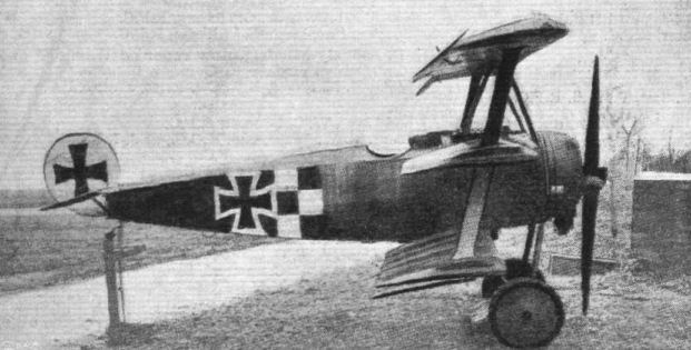
Side view of the Fokker triplane.
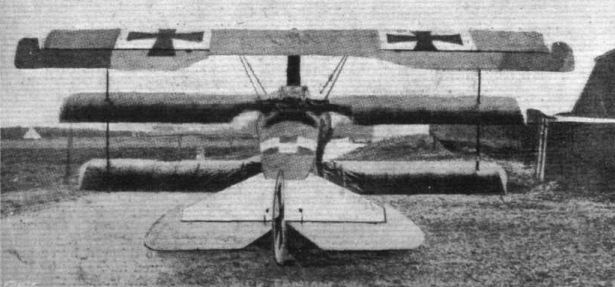
The Fokker triplane from behind.
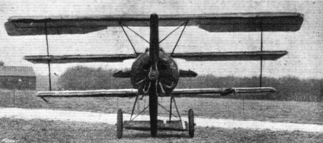
Front view of the Fokker triplane.
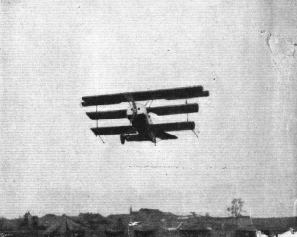
The Fokker triplane in flight.
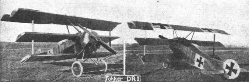
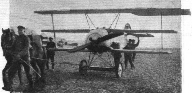
121 h.p., the 120 being provided by the motor. - Wheeling a Fokker triplane out n the aerodrome.

Getting Ready to Start. - A pair of Fokker triplanes in their native land.
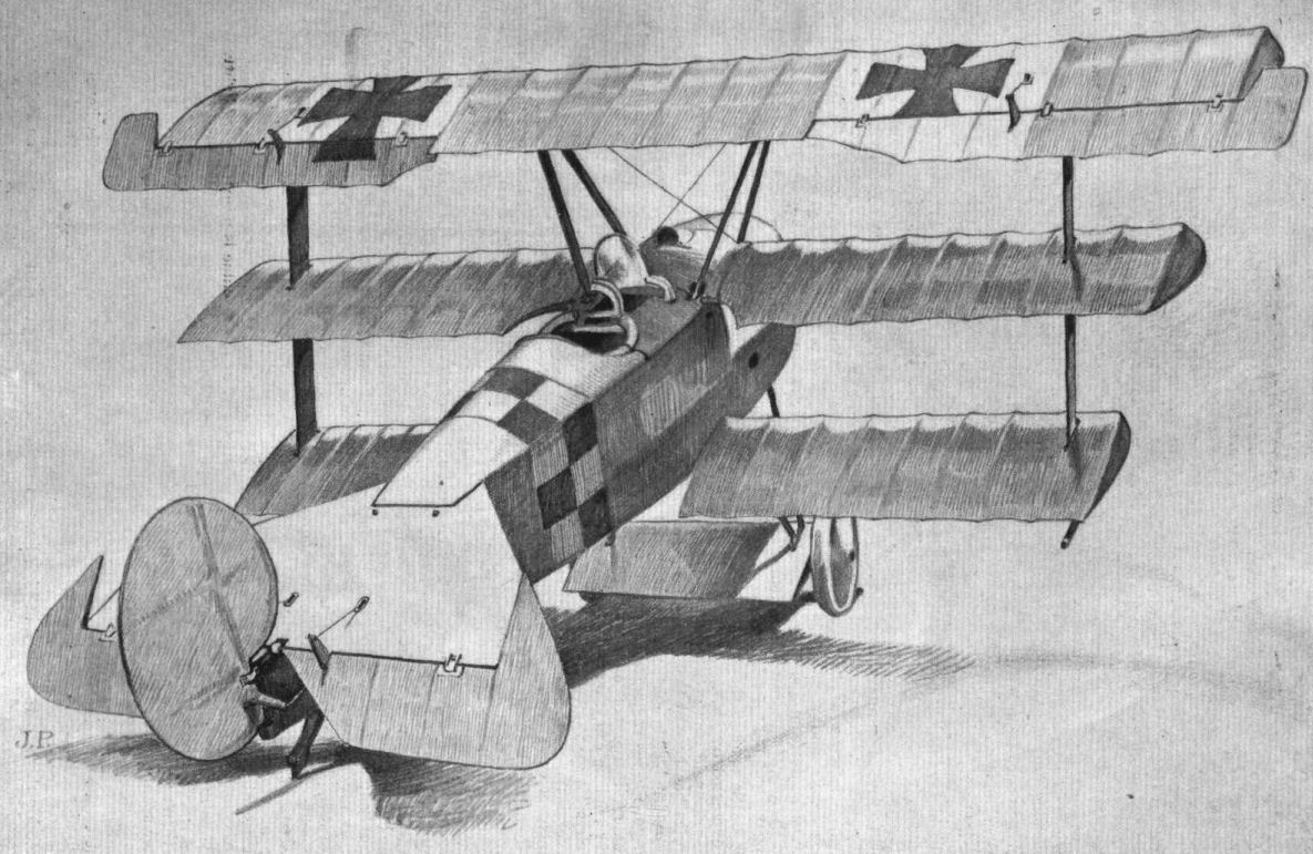
THREE-QUARTER REAR VIEW OF THE FOKKER TRIPLANE. - This illustration gives a good idea of the general arrangement of this interesting machine. Note the small ply-wood plane enclosing the wheel axle.
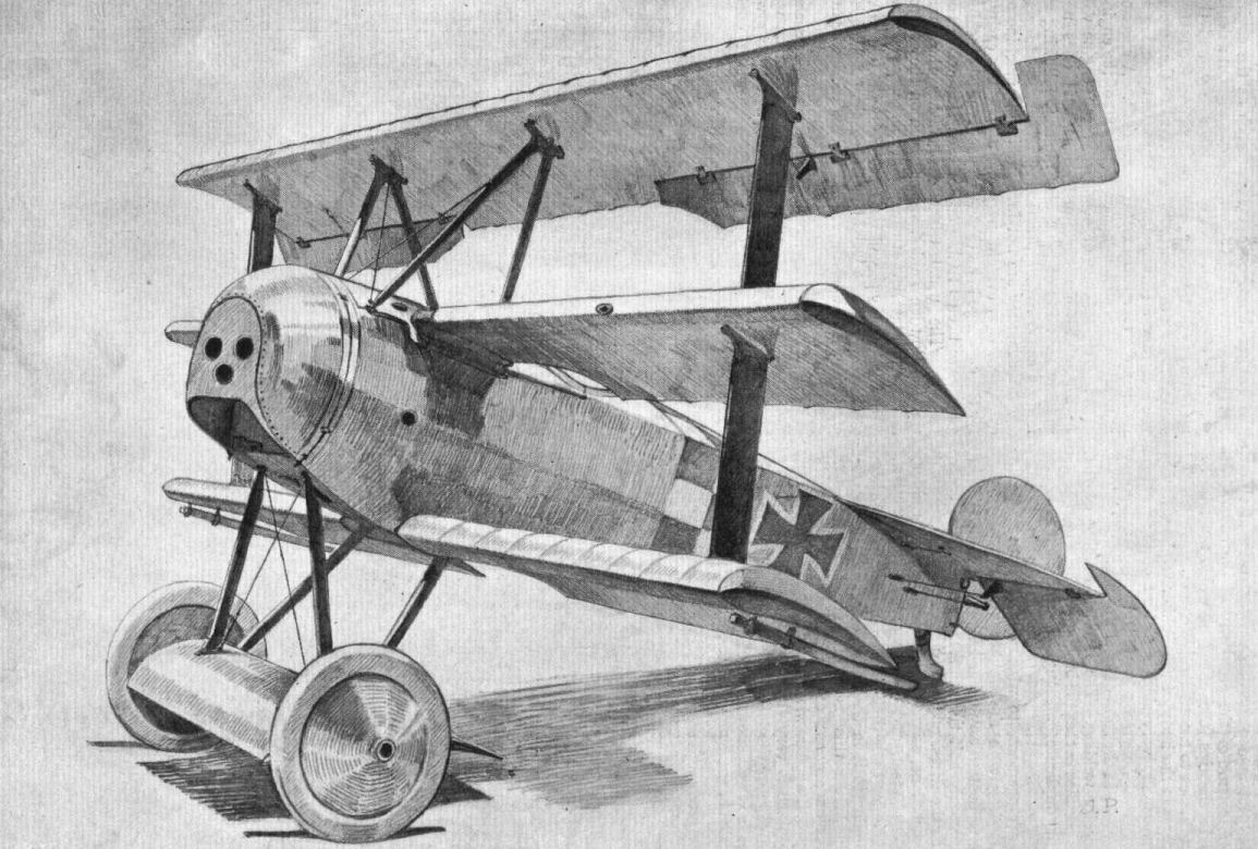
THREE-QUARTER FRONT VIEW OF THE FOKKER TRIPLANE. - The thickness of the wings can be imagined from an inspection of this drawing. The pin-jointed struts are really ties rather than struts as they are working in tension.
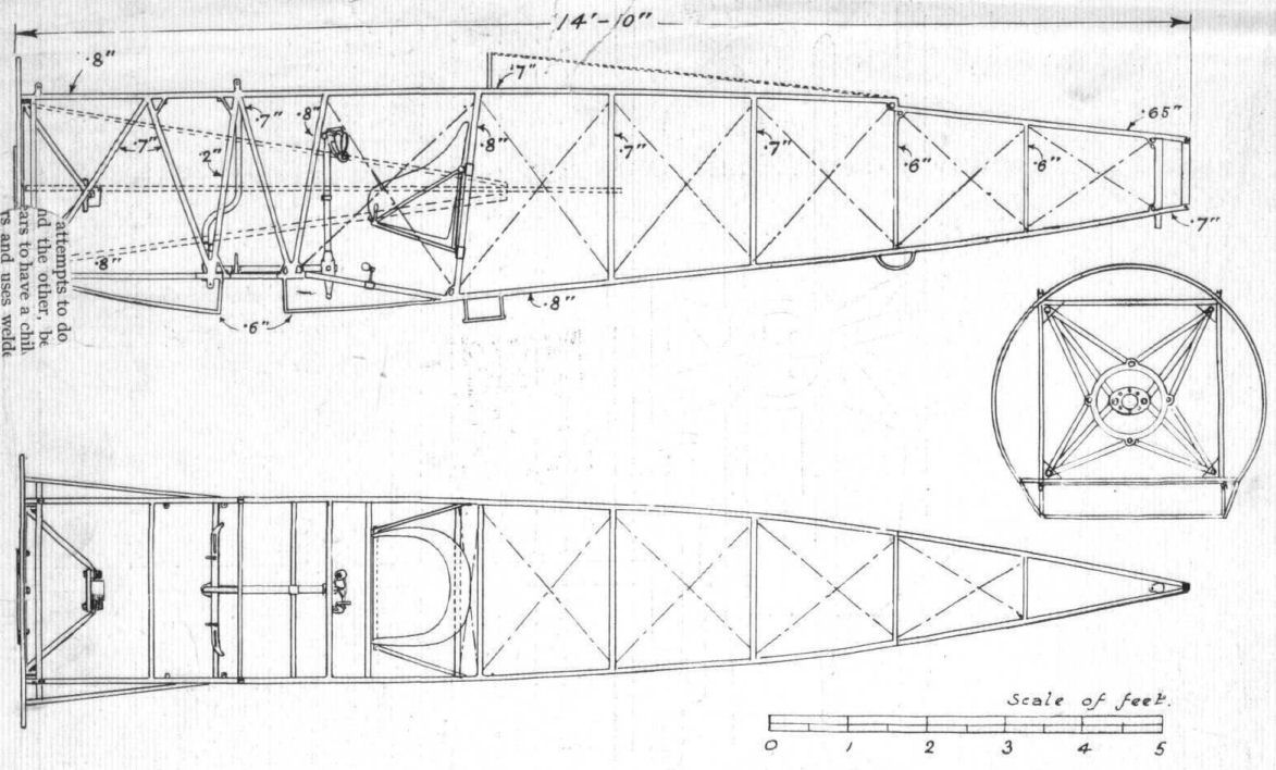
Fig. 1. - Plan and elevation of the body of the Fokker triplane to scale. Note the slot for accomodating the lower wing spar, and the drop in the top longerons for the fixed tail plane.
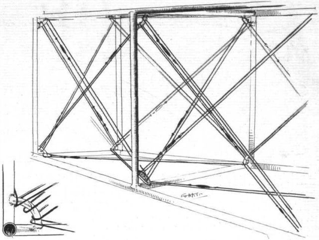
Fig. 2. - Sketch showing the bracing system employed in the body of the Fokker triplane. The wires only appear to be in duplicate. Inset shows tubular quadrant serving as an anchorage for all the bracing wires.

Fig. 3. - Sketch showing the three-ply fairings and their attachment on the Fokker triplane. The fork end brackets for the two machine guns should be noted.
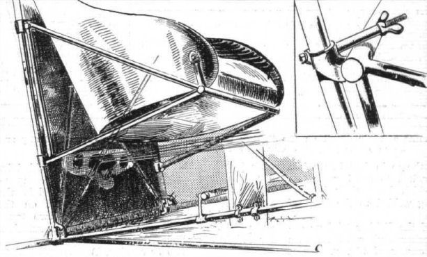
Fig. 4. - The pilot's seat of the Fokker triplane. By means of the split collar and bolt arrangement shown in the inset, the seat may be quickly raised or lowered to suit the pilot.

Fig. 5. - The controls and some of their detail on the Fokker triplane. The insets show a typical clip and some of the purposes for which it is employed.
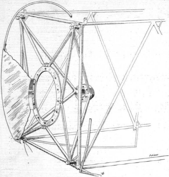
Fig. 6. - General arrangement of the engine mounting on the Fokker triplane.
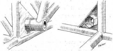
Fig. 7. - Details of the engine mounting on the Fokker triplane.

Fig. 8. - The tail skid and its attachment on the Fokker triplane. On the right, details of the shock absorbing arrangement.
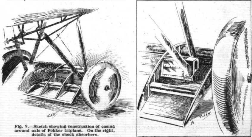
Fig. 9. - Sketch showing construction of casing around axle of Fokker triplane. On the right, details of the shock absorbers.
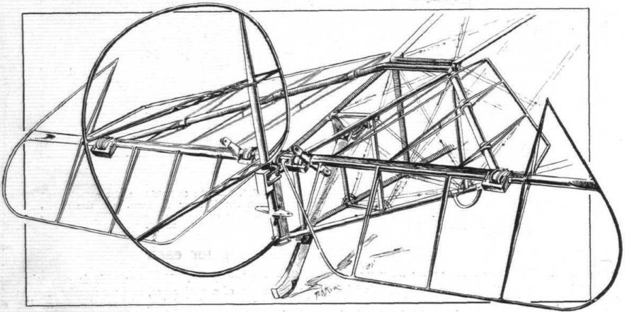
Fig. 10. - The tail planes of the Fokker triplane.

Fig. 11. - Some of the wing details of the Fokker triplane.
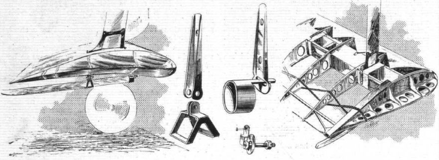
Fig. 12. - Details of the wing tip and its skid on the Fokker triplane.
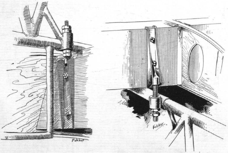
Fig. 13. - Attachments of wing spars to body on the Fokker triplane. On the left is shown the attachment of the bottom plane, while the sketch on the right shows how the middle plane is secured to the top body rails.
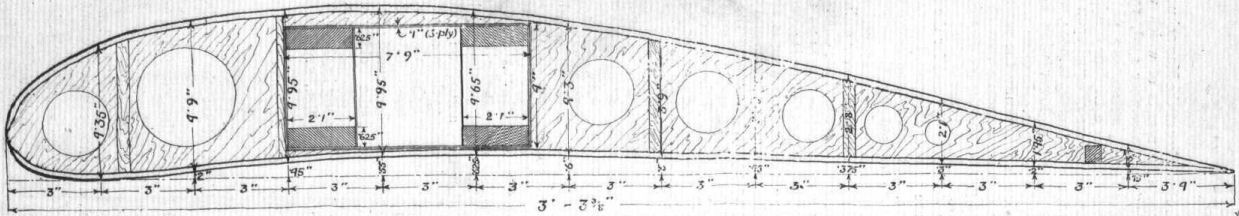
Fig. 14 - The wing section, to scale, of the Fokker triplane. The web of the rib is made of very thin three-ply wood, and the flanges of spruce. The composite spar consists of four strips of spruce and of a box made of plywood.

Fig. 15. - A comparative sketch showing differences between the Fokker wing section and Dr. Schukowsky's aerofoil, described in "Properties of Aerofoils," by A. W. Judge. The Fokker section is shown in full lines. It will be noticed that only the trailing portion of the upper surfaces of the two sections coincide.
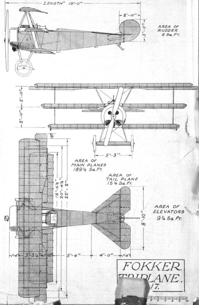
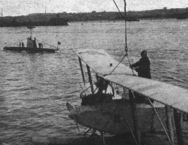
Launching a German Seaplane from a Mother Ship. In the background a U. boat.
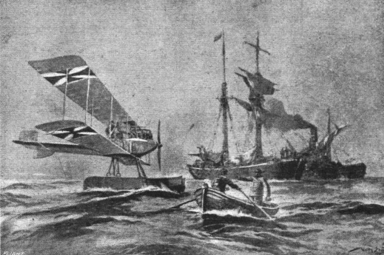
A picture of a German seaplane which has captured a Russian sailing vessel in the Baltic.
Flight, July 4, 1918.
REPORT ON THE FRIEDRICHSHAFEN BOMBER.
[Issued by the Technical Department (Aircraft Proiuction), Ministry of Munitions.]
THIS machine, which bears the mark F.D.H. G.3. 326/17, was brought down by anti-aircraft fire at Isbergues on the night of the 16th February. A shell made a direct hit on the right-hand engine at a height of 8,000 to 9,000 ft., after which the machine covered about six miles and made a fairly good landing.
Various parts of the structure bear different dates, that on the tail being 14/1/18. The main spars are branded with a small crown and the letters Z.A.K. The following is painted on the side of the body :-
Leergewicht (weight empty), 2,695 kilogrammes = 5.929 lbs.
Nutzlast (useful load), 1,235 kilogammes = 2,717 lbs.
Zulassiges Gesamtgewicht (permissible total weight), 3.930 kilogrammes = 8,646 lbs.
Crew.
This machine carried its full complement of four persons, namely, pilot, fore-gunner, after-gunner, and bomber. It is known, however, that the number of crew varies considerably, as some machines of this type have only carried two persons. The accommodation is so arranged that the personnel can easily change places, all the cockpits being inter-communicating.
General Description.
The general design of the machine is shown in the attached drawing, which gives plan and front and side elevations.
The principal dimensions are as follows :-
Span 78 ft.
Maximum chord 7 ft. 8 ins.
Gap 7 ft.
Dihedral angle in
the vertical
plane 1 1/2#
Dihedral angle in
the horizontal
plane 6#
Total area of
main planes 934.4 sq.ft.
Area of upper
main planes
without flap 480 "
Area of lower
main planes
without flap 454.4 "
Load per sq. ft. 9.24 lbs.
Weight per h.p. 16.6 lbs.
Area of flap of
upper wing 21.6 sq. ft.
Balance area 1.8 sq.ft.
Area of flap on
lower wing 1.6 "
Balance area 1.56 "
Total area of fixed
tail planes 57.6 "
Total area of elevators
32 "
Balance area of
one elevator 1.7 "
Area of fin 20 "
Area of rudder 19.2 "
Balance area of
rudder 3 "
Maximum cross
section of body 19.2 "
Horizontal area
of body 133 "
Vertical area of
body 131.2 "
Length overall 42 ft.
The machine is built up upon a central section, to which are attached the forward and rearward portions of the fuselage and the main planes. This central section comprises the main cell or cabin of the body containing the tanks bombs, &c. It also embraces the engines and the central portion of the upper and lower planes. The latter, together with the engine struts, are largely built up of steel tube, as is also the landing gear.
The central portion of the body, which measures 4 ft. across by 4 ft. 3 ins. in height, consists of a box formation made of ply wood, strengthened by longerons and diagonals, and transversely stiffened by ply-wood bulkheads. The bulkhead furthest forward acts as an instrument board, behind which are side by side the seats of the pilot and his assistant. The former has a fixed upholstered seat, whilst that of the latter is folding, consisting of a light steel tubular framework with a webbing back-rest.
Underneath these two seats is the lower main petrol tank. Behind this cockpit the body is roofed in with ply wood, the rear part of which roofing is detachable so as to give access to the second main petrol tank, which is at the rear end of the main body section. By this means a small cabin or covered passage-way is provided, at each side of which are the racks for the smaller bombs.
Central Portion of Wings.
The central and non-detachable portion of the upper plane has a span of 19 ft. 5 ins., whilst at each side of the nacelle the lower plane fixed portion measures 7 ft. 8 ins. The main wing spars in this central portion are of steel tube, roughly 2 ins. in diameter, with a wall thickness of 1/16 in.
As shown in the photograph Fig. 1, these spars are braced by steel tubes arranged in the form of an X, the manner in which the bracing tubes are attached to the main spars being shown in the sketch Fig. 2.
The lugs are built up by welding, and are pinned and riveted in position, the joint being of the plain knuckle type.
The upper-surface of the lower plane is, so far as the central section is concerned, covered in with three-ply wood. In this portion the main ribs are of three-ply, with spruce flanges. Between each main rib is a cut-away rib, the design of which is shown in the sketch Fig. 3. This, unlike the main ribs, is one piece of wood, and not built up. For the greater part of its length it applies to the top surface only, being cut away to pass clear of the-cross bracing tubes.
As shown in the photograph Fig. 1, the plane is further stiffened with transverse members consisting of three-ply panels between each rib strengthened by grooved pieces top and bottom. The latter are attached as shown in the sketch Fig. 4, and the attachment of the flanges of the main ribs is shown in Fig. 5.
The central section of the upper main plane is in one piece, and is covered top and bottom with fabric. In order to facilitate the removal of the engines, detachable panels measuring 1 ft. 11 1/2 ins. long by 1 ft. 8 ins. deep are let into the trailing edge immediately over the engine bearers. These panels are socketted in front, and at the rear are joined up at the trailing edge with U-section sheet steel clips and bolts.
The struts which connect the top of the nacelle to the upper plane are tubular and of streamline section, as are also the engine bearer struts. A section of one of the latter is given in Fig. 6. The thickness of the wall is one-sixteenth of an inch.
The method of attaching the lower end of the engine struts to the tubular steel spars is shown in the sketch Fig. 7, from which it will be seen that a welded Y socket is used and secured by a pin joint, the ends of the pin acting as anchorages for the attachment of the bracing wires.
This sketch also shows the lugs which respectively support the detachable portion of the main planes and the vertical strut of the landing chassis. The engine bearer struts are pushed into the Y socket and pinned in position, the pins being afterwards brazed into the socket. At their upper ends the engine struts are fixed to the top plane spars with pin joints, as shown in Figs. 8 and 9, the attachment differing according to the number of wire bracings that are to be taken to each joint.
Construction of Wings.
The detachable portions of the wings are fixed to the centre section by pin joints, one part of which is shown in Fig. 7, the male portion being represented in Fig. 10. The chord of the wing in the line of flight varies from approximately 7 ft. 8 ins. to 7 ft, 5 ins., and the wing section is shown shaded in Fig. 11. In order to provide a basis of comparison the R.A.F. 14 wing section is superimposed and drawn to the same scale.
The main spars are placed one metre apart, the front spar being 272 mm. in the rear of the leading edge. Both spars are of the built-up box type, as shown in Figs. 12 and 13. The former is the leading spar and the latter the rear spar. These spars are of spruce, and each half is furnished with several splices, so that the greatest single length of timber in them is not more than 14 ft. The splices, which occur in each half alternately, are of the plain bevel type about 15-ins. long and wrapped with fabric. A fabric wrapping is also applied at short intervals along the spar.
Internal cross bracing between the main spars is afforded by steel tube cross members and cables attached as shown in the sketch Fig. 10.
The main spar joint consists of a steel plate 19 mm. thick embedded in the spar end and held in position by 5 bolts, which pass through a strapping plate surrounding the end of the spar. This plate also carries the attachment for the bracing cable, and is furnished with a spigot which locates the bracing tube. It w 11 be seen that at this point the spar is provided with tapered packing pieces of hard wood glued and held in position by fabric wrapping.
The main ribs are placed 360 mm. apart. Between them are auxiliary formers, consisting of strips of wood 20 mm. x 10 mm. thick, which run from the leading edge to the rear spar. The main ribs consist of ply wood webs socketted into grooved spruce flanges, which are tapered off as shown in Fig. 5, except where they are met by a longitudinal stringer. The leading edge is solid wood moulded to a semi-circular section of approximately 65 mm. diameter. Where the rib web abuts against it, packing pieces are glued each side. Between the main spars the web of the rib is divided by three vertical strips into four panels, and in each of these it is perforated, leaving an edge all round about 72 mm. wide.
As shown in Fig. 10, the.upper flange of the main ribs is carried clear of the leading spar by means of packing pieces. In the case of the rear spar, packing pieces are also used under the rib flange, as shown in Fig. 14.
The lower main planes for a width of about 2 ft. 3 ins. at their inner end are covered as to their top surface with three-ply wood.
The interplane struts are attached to the main spars by joints of the type shown in Fig 15. This, it will be seen, follows the typical German practice of partially universal jointed mountings for the cable attachments. At the points of attachment of these strut joints, suitably tapered packing pieces of hard wood surround the spars, which at these points arc also wrapped with fabric.
Struts.
Outside of the centre section the interplane struts are of wood built up, as shown in the section Fig. 16, of five separate pieces. The curved portions are of timber which has not yet been identified, but is apparently of poor quality. The cross web is of ash. The strut is wrapped at frequent intervals with strips of fabric and is fitted with a socket joint of the type shown in Fig. 17. The outer pair of struts are of smaller section than the main struts, but are built up in a similar manner. Their section is 125 mm. x 40 mm.
Ailerons.
The framework is principally of welded steel tube wrapped with fabric.
A notable point is the thick section of the leading edge of the balanced portion, as shown in Fig. 18.
Fin and Fixed Tail-planes.
The framework of these is steel tube, and in the case of the tail-planes wooden stringers running fore and aft are arranged at intervals. The tail-planes are supported by diagonal steel tubes of streamline section, on the under side of which sharp steel points are welded to prevent these stays being used for lifting purposes.
Elevators and Rudders.
The framework in each case is of steel tube, the main tube being 35 mm. in diameter and the remainder 15 mm.
Bracing.
Throughout the wings, both internally and externally, the bracing is by means of multistrand steel cable.
Fuselage (Rear Portion).
At the after-gunner's cockpit the section of the fuselage has a rounded top, which is gradually smoothed down into flat. The section, for the greater part of the length, is rectangular, and the frame is built up in the usual manner with square section longerons and verticals, the joints being arranged as shown in Fig. 19. The cross bracing wires along the sides, top, bottom, and diagonal are of steel piano wire and are covered with strips of fabric, as shown in this sketch, where they lie adjacent to the fabric fuselage covering.
The vertical and horizontal compression members are located by spigots. The joint consists of a plate which completely surrounds the longerons, its two ends being riveted together to form a diagonal bracing strip. For the last few feet at the tail the fuselage is covered with thin three-ply.
Fig, 20 is a view looking down the rear portion of the fuselage. The fuselage is covered with fabric, which is held in position by a lacing underneath, and is consequently bodily removable.
The floor of the after-gunner's cockpit is elevated above the bottom of the fuselage. Immediately underneath this cockpit is a large trap door, shown in the photograph No. 20, and also by dotted lines in the plan view of the aeroplane. This is hinged at its rearward end and furnished with two large celluloid windows. It is held in its "up" position by a long spring and a snap clip. No means could be found by which it could be fixed in its closed position. As footsteps are provided for all the cockpits, this trapdoor is evidently not intended for ingress and egress. It could be employed in connection with a machine gun firing backwards, as in the Gotha, but no machine gun mounting was fixed in this machine for this purpose.
The rear portion of the fuselage is attached to the centre section of the body by a clip at each corner. This is shown in Fig. 21. The rear portion carries a male lug, shown in Fig. 50, which engages with the two eyes, and is held in position by a three-eighths bolt. Four other bolts in tension pass through the sheet metal clip, as shown in the sketch. In each case the lugs are furnished with sheet steel extensions which, as shown in the sketch Fig. 21, are sunk flush into the top and bottom surfaces of the fuselage longerons and are there held with three bolts. The corner joint is welded sheet steel, and there is an additional sheet steel joint which serves the secondary purpose of providing an anchorage for the bracing wires. As this fuselage joint is level with the plane of rotation of the propellers, it is armoured both on the nacelle and on the rear portion of the fuselage with a hinged covering of stout sheet steel lined with felt. A plate of armour a foot wide also extends down each side of the nacelle at this point.
(To be continued.)
Flight, July 11, 1918.
REPORT ON THE FRIEDRICHSHAFEN BOMBER.
[Issued by the Technical Department (Aircraft Production), Ministry of Munitions.]
(Continued from page 741.)
Forward Cockpit.
THIS is attached to the main body by four bolts with clips similar to those just described. It consists of a light wooden framework, covered throughout by three-ply. Two views of this portion of the machine are given in the photographs Figs. 22 and 23. This cockpit can be divided off from the main cockpit by means of a fabric curtain. Its occupant is provided with the folding seat, as shown, and manages a gun and the bomb dropping gear.
Engine Mounting.
The engine bearers have the section shown in Fig. 24, and are each built up of two pieces of pine united by tongues. On their top surface they are faced with ply wood and at the bottom with ash. A strip of ash applied to the upper outer corner of the bearer gives it an "L" section, and has screwed into it the threaded sockets for the set screws of the lower part of the engine fairing. The engine bearers taper sharply at each end. They are mounted on the "V" struts by means of acetylene welded brackets, constructed as shown in sketch, Fig. 25. These, it will be seen, are of box form, and form a line round the streamline tube.
The engine cowling is a particularly fine piece of work, and two views are given in sketches 26 and 27. The lower portion is attached to the engine bearers by set screws, but the upper part is readily detachable, being furnished with turn buttons. This cowling allows the cylinders of the engine to be exposed to the air. A large scoop is placed in front, so as to permit a free flow of air over the bottom and sides of the crank chamber, whilst at the rear three large trumpet shaped cowls are provided so that a draught of air is forced against the crankcase in the neighbourhood of the carburettor air intake. In the rear the fairing abuts against the propeller nave, whilst in front it is attached to the radiator. It will be noticed that at each side of the radiator are narrow air scoops, the object of which is to promote a draught past the oil tank and front cylinder heads.
Engines.
The motors are the standard 260 h.p. Mercedes with six cylinders in line. Full details of this engine have been published, and it is only, therefore, necessary to notice one or two points in connection with the installation.
A new departure is the interconnection of the throttle and ignition advance controls. This is carried out in the manner illustrated diagrammatically in Fig. 28. It will be seen that a considerable movement of the throttle can be made independently of the ignition advance. In the Mercedes carburettor the throttle is so arranged that it cannot be fully opened near the ground without providing too weak a mixture, and it is thought possible that the full ignition advance is not obtained until this critical opening is reached.
On several German bombing aeroplanes grease pumps for lubricating the water pump spindle have been found. Fig. 29 shows the design as fitted to the Friedrichshafen. It consists of a ratchet and pawl operated grease pump, secured by a bracket to one of the engine struts, and worked from the pilot's cockpit by a lever, and a stranded steel cable passing over a pulley, the pawl being returned by a long coiled spring.
The engine numbers are respectively MN.32299 and MN.36228.
Photograph Fig 30 shows the exhaust pipe. This is of new design, although it incorporates the well-known expansion joints attached to the flanges. It will be seen that it is fitted with what amounts to a rudimentary silencer, whereas in previous machines of a similar type to the Friedrichshafen an open-ended exhaust pipe was used.
Radiators.
Each radiator is provided with an electric thermometer fitted into the water inlet pipe, as shown in the sketch, Fig. 32, these thermometers being wired up to a dial on the dashboard, which is furnished with a switch, so that the temperature of either radiator can be taken independently.
Each radiator is provided with an electric thermometer fitted into the water inlet pipe, apparently square tubes to the number of 4,134, and measuring roughly 6 mm. each way. The radiator with shutter full open is shown in Fig. 33.
The honeycomb radiators are of "V" section, and each is provided with a shutter which covers up a little more than a third of the cooling surface. This shutter is fitted with a stop, so that when fully opened it lies in the line of flight of the aeroplane. It is opened or closed according to circumstances by the gear, shown in the sketch, Fig. 31, of which the handle is mounted on the roof of the nacelle, immediately behind the pilot's seat. Three positions are provided for the handle, which operates the two shutters simultaneously by means of return cables.
Immediately above the main radiator, and let into the upper main plane between the front spar and the leading edge, is a small auxiliary tank, illustrated in Fig. 34. This is furnished with a trumpet shaped vent in the direction of the line of flight, and is furnished with two outlets, one to the head of the main radiator, and the other to the water-pump. The function of this tank is evidently to prevent the pump from priming.
Oil Pump.
The main supply of oil is carried in sumps forming part of the base chamber. A secondary supply of oil, from which a small fresh charge is drawn at every stroke of the oil pump, is contained in a cylindrical tank supported by brackets from the engine struts, and placed immediately behind the radiator. This tank is shown in photograph Fig. 35, and has a capacity of 25 litres = 5 1/2 gallons. Each tank is furnished with a glass level, which is visible from the pilot's seat.
Petrol Tanks.
The two main tanks, which are placed, one under the pilot's seat and the other at the top rear end of the nacelle, contain 270 litres = 59 1/2 gallons each, and are made of brass. Each is provided with a Maximall level indicator, which employs the principle of a float operating a dial by means of a cable enclosed in a system of pipes.
A hand pump is fitted convenient to the pilot, and pressure is normally provided by the pumps installed in each engine. An auxiliary tank, holding approximately 13 gallons, is concealed in the upper main plane, not immediately over the nacelle, but a little to the left side. This auxiliary tank is fitted with a level, as shown in Fig. 36, which is visible from the cockpit. The auxiliary tank appears to be used only for starting purposes. It is covered with a sheet of fabric held in position by "patent fasteners." A photograph is given in Fig. 37.
Engine Controls.
Running from each engine to the nacelle is a horizontal streamline casing, containing the various engine controls. A section showing the arrangement of these inside the fairing is given in the sketch. Fig. 38. The leading edge of the streamline casing consists of a steel tube, to which are welded narrow steel strip brackets, to the rear end of which are bolted thinner strips which are hinged in front to the tube. The whole is then enclosed in a sheet aluminium fairing.
Through the leading tube passes the throttle control rod for each engine, the two throttles being worked either together or independently by the ratchet levers, shown in Fig. 39. These are mounted on a shelf convenient to the pilot's left hand. This control requires a considerable number of bell cranks and countershafts, but was noticeably free from backlash. The throttle is opened by the pilot pulling the levers towards him.
On the dashboard are two revolution counters and two air pressure indicators. The metal parts of these dials are painted red for the left engine and green for the right, and the same colouring applies to the magneto switches, one of which contains a master switch which applies to both magnetos on both engines.
Piping.
The various systems of piping are distinguished by being painted different colours, thus the petrol pipes are while, arrows being also painted on them to show the direction of flow; air pressure pipes are blue, and pipes for cable controls grey.
Propeller.
The propellers are made by the Luckenwalde Propellerwerke, Niendorf, Each propeller is 3.08 metres in diameter and is made of nine laminations, which are alternately walnut and ash, except one, which appears to be of maple. Photographs, Figs. 40 and 41, show the propeller, which has the last 20 ins, of its blade edged with brass. The pitch is approximately 1.8 metres and the maximum width of the blade 220 mm.
(To be concluded.)
Flight, July 18, 1918.
REPORT ON THE FRIEDRICHSHAFEN BOMBER.
[Issued by the Technical Department (Aircraft Production). Ministry of Munitions.]
(Concluded from page 773.)
Controls.
ONLY one set of control gears is fitted; but, as pointed out, the seating accommodation is so arranged that any of the crew can take charge if, and when, necessary.
The elevator and aileron control is shown in sketch Fig. 42. It consists of a tubular steel pillar mounted on a cranked cross bar at its foot. The ailerons are worked by cables passing over a drum on the wheel, whence they descend through fibre guides on the cross bar to another wheel mounted on a countershaft below, from which they are taken along inside the leading edge of the lower wing and finally over pulleys up to the aileron levers on the top plane. The latter are partially concealed in slots let into the trailing edge of the wing. The upper and lower ailerons are connected by means of pin jointed tubular steel struts of streamline section.
It will be observed from Fig. 42 that a locking device whereby the elevator control can be fixed in any desired position is fitted, and consists of a slotted link which can be clamped by a butterfly nut to the control lever. This link is hinged to a small bracket attached to the panel below the pilot's seat.
Fig. 43 shows the rudder control, from which cables are taken over pulleys and through housings in the nacelle and finally to the end of the fuselage. The cranked rudder bar is of light steel tube, and is arranged to be placed in the pivot box in either of two positions. It is furnished with light steel tubular hoops which act as heel rests and are adjustable. A locking clip is fitted on the floor of the cockpit so that the rudder can be fixed in its neutral position.
A novel type of trimming gear is an interesting item of the control. Movement of the elevator control from the normal upright position of the stick is made against the tension of one of two springs which can be alternately extended and relaxed by means of a winch connected to them, as shown in the diagram, Fig. 44. Normally these springs tend to bring the control stick back to a central position, in which the elevator lies flat, but if one of the springs is tensioned by winding up the winch in a clockwise direction, the position to which he stick will tend to come when released will be such as set the elevator at a positive angle. This winch gear, which is illustrated in Fig. 45, is mounted on the right-hand side of the nacelle, and is therefore under the command of the pilot's companion.
The crank is furnished with a locking pawl, which engages with a ring of small holes bored in the plate of the winch. The steel springs used in conjunction with this apparatus are some 3 ft. long and about f in. in diameter. The inscription behind the winch reads:
Nose heavy - Right wind.
Tail heavy - Left wind.
Landing Gear.
As might be expected, the landing gear on this machine is of massive proportions. Two vertical streamline section wood-filled tubes descend from the centre section wing spars, immediately under the engine, to a bridge piece or hollow girder made of welded steel. This is shown in the photograph Fig. 46. Through an oval hole in this girder a short axle carries two 965 mm. X 150 mm. wheels (38 ins. x 6 ins.). These work up and down against the tension of a bundle of steel springs about 1/2 in. in diameter and made of wire approximately 1/16 in. thick. The steel girder is extensively pierced for lightness, and the edges of the holes are swaged inwards. The axle is prevented from moving sideways by plates, and is provided with short steel cables which act as radius rods and connect it to the front of the girder. The whole of the box girder is covered in with a detachable bag of fabric, which extends up to the small cross bar mounted immediately above the girder.
Mudguards are provided behind each landing wheel for the purpose of preventing any mud or stones dislodged by the wheels from coming in contact with the propellers.
From the front and rear of the box girder streamline tubes are taken to the ends of the main wing spars, where they abut against the nacelle, and these diagonals are further braced with streamline steel tubes. Both the vertical and diagonal tubes are held in split sockets so as to be easily replaceable if damaged.
In addition to the four main landing wheels, a fifth is mounted under the nose of the fuselage, as shown in the photograph Fig. 47. This wheel is 760 mm. x 100 mm. (30 ins. x 4 ins.). It is mounted on a short tubular axle, which is capable of sliding up and down slots in its forks against a strong coil spring, and it is also capable of a certain amount of lateral movement along its axle, also against the action of two small coil springs.
The tail portion of the fuselage is protected by a fixed skid made of wood but shod with a steel sole. This is arranged, as shown in photograph Fig. 48, and is fitted with a small coil spring contained inside the fuselage.
The whole of the wiring system on the machine is very neatly carried out. There are three main systems; firstly, the ignition wiring, which is contained for the most part in tubes of glazed and woven fabric, secondly, the heating system, for which the wires are carried in flexible metal conduits, and thirdly, the lighting system, in which a thin celluloid protective tubing is used. Wires are run from the nacelle along the leading edge of the upper planes to points level with the outermost strut. Here they terminate in a plug fitting placed behind a hinged panel. Apparently lamps are intended to be served by this circuit. Immediately in front of the pilot's seat a universally jointed lamp bracket is Fig. 45. mounted on the outside of the nacelle. The exact purpose of this lamp is not known, as it could not illuminate any instruments.
Armament.
Both the forward and rear cockpits are furnished with swivel gun mounts carrying Parabellum machine guns. These mounts consist of built-up laminated-weed turntables, working on small rollers, and carry a U-shaped tubular arm for elevation. This arm is hinged to a plunger red working through a cross head, and arranged so that the arm is normally pulled down flat on the turntable by a coil spring. The plunger can be locked in any of a series of positions by means of a bolt operated by a hand-lever through a Bowden wire. A second lever allows the turntable to be locked at any desired point. A perforated sheet-metal shield protects the cross head and spring. Small shoulder pads are fixed on the turntables, of which that in the forward cockpit has a diameter of 2 ft. 10 1/2 ins., whilst in the rear the diameter is 3 ft- of in.
A photograph of the forward gun mounting is given in Fig. 49.
The after-gunner is prevented from damaging the propellers by two wire netting screens supported by tubular steel brackets, placed on either side of his cockpit. These are sketched in Fig. 50.
In addition to these two guns, provision is made for mounting a third in front of, and to the right of, the pilot's cockpit, where it could be managed by his companion. For this purpose a clip is provided immediately under the coaming of the nacelle, and the handle of this protrudes through a slot in the dashboard. The clip works on the eccentric principle, and appears to be self-locking. Its construction is shown in detail in Fig. 51.
A rack for Verey lights is mounted on the outside of the nacelle convenient to the pilot's companion.
Instruments.
Airspeed Indicator.
Considerable interest attaches to the fact that this Friedrichshafen Bomber is the first enemy machine brought down which has been found provided with an airspeed indicator. This is of the static type, embodying a Pitot head of the unusual type. The indicator has a dial of large size, and is altogether a much more bulky instrument than any of a similar purpose used on British machines. An investigation of its mechanism is being made.
Altimeter.
This is of the usual type, reading to 8 kilometres.
Level Indicator.
This is a somewhat crudely made device, employing two liquid levels, as indicated in the diagrammatic sketch Fig. 52. It will be seen that the reading gives the pilot an exaggerated idea of the angle of roll. The glass tubes are sealed up, and contain a dark blue liquid. One side of the dial is engraved Hangt links (Hangs left), the other Hangt rechts (Hangs right). The manufacturer is Arno Weisse, Berlin.
Revolution Counters.
The dials give readings from 300 to 1,600 r.p.m. The sector between 1,300 and 1,500 is painted black, and these figures are marked with luminous compound, as also is the indicating hand. The manufacturer is Wilhelm Morell, Leipsig.
Air Pressure Gauges.
These read from o to 0.5 kilogrammes per square centimetre. There is a red mark against the figure 0.25 kg. The manufacturer is Maximall Apparate Fabrik, Berlin.
Electric Thermometer Dial.
This dashboard instrument consists of a box-type meter, the dial reading from 0 to 100 C. The figures 0 and 75 are accentuated by red marks. A switch at the side of the box, having positions marked 1 and 2, allows the temperature of either radiator to be read.
Petrol Level Indicators.
These are of the Maximall type, and employ a float immersed in a tubular guide in the tank. This float communicates its motion to a finger working over a circular dial, by means of a thin cord passing over pulleys. These are encased in pipes which are under the same pressure as the tank.
Electric Heating Rheostat.
This is illustrated in Fig. 53. It is marked Aus (off), Schwach (weak), Stark (strong). There are two separate resistance coils, enabling the rheostat also to perform the function of a change-over switch.
Wireless.
The machine is internally wired for wireless, and the left-hand engine is provided with a pulley and clutch for driving the dynamo. Reference to Fig. 26 will show that this is designed to be mounted on a bracket carried by the outside front engine bearer strut, and that the engine fairing is moulded to receive it.
Bombs and Bomb Gear.
At each side of the covered-in passage-way in the nacelle are bomb racks, shown in Fig. 54, capable of holding five 25-pounder (12 kg.) bombs. Underneath the nacelle are carried two large tubular frames, fitted with cradles of steel cable and furnished with the usual form of trip gear. These racks, illustrated in Fig. 55, would, it is believed, be capable of supporting a 300 kg. bomb a-piece. The bombs carried, however, evidently vary with the radius of action over which the aeroplane has to operate. The large racks are not permanently attached to the nacelle, but can easily be removed as required.
Fig. 23 shows the inside of the front cockpit from which the release of the bombs is conducted. There are seven triggers for the small bomb racks and two levers for the large bomb trips, as shown in Fig. 56. The cables for this gear are carried under the floor, and are painted different colours for distinction.
Bomb-sight.
The bomb-sight carried on the machine presents no new features, and is of the ordinary German non-precision type.
Fabric and Dope.
Two entirely different kinds of fabric are employed in the Friedrichshafen machine. The wings are covered with a low-grade linen of the class which is employed on most of the enemy machines. It is white in colour. Compared with that of British fabrics, the tensile strength is fairly good.
This fabric is covered with a cellulose acetate dope, and is camouflaged in large irregular lozenges of dull colours, including blue-black, dark green, and earth colour.
The other fabric, which is applied to the fuselage, tail planes, rudder, elevator, fin and landing gear, is apparently a cheap material much inferior to British fabrics designed for a similar purpose. This fuselage fabric is dyed in a regular pattern of lozenges, the colours being hardly distinguishable from black. The dope is acetate of cellulose.
In both cases the dope seems to be carelessly applied.
Changes in Design.
When compared with the Fdh. GUI., No. 177/17 (of 13/9/17) brought down by the French, this Friedrichshafen presents a few differences in detail design, amongst which the following points may be noted :-
(1) Engine fairing. In No. 177 spinners were mounted on the propeller bosses, and an aluminium ring of large diameter mounted on the rear extremities of the engine bearers in order to carry the rearmost fairing panels.
(2) Exhaust pipe. In the No. 177 this was, as in the present case, trumpet shaped and turned back at the end, but instead of a series of slots being used, the open vent was "bottled" so that the orifice was slightly restricted, and an additional circle of small holes provided.
(3) Engine bearers. These were of ash in the No. 575, and the L-shaped extension was not used. The method of building up the bearers was, however, similar to that described.
(4) The weight empty was 2,665 kg. in the No. 177, as against 2,695 in the machine under review.
(5) The air-scoops under the engine fairing were smaller.
(6) The arrangement of the instruments, taps, &c, on the dashboard was quite different.
REPORT ON THE FRIEDRICHSHAFEN BOMBER.
[Issued by the Technical Department (Aircraft Proiuction), Ministry of Munitions.]
THIS machine, which bears the mark F.D.H. G.3. 326/17, was brought down by anti-aircraft fire at Isbergues on the night of the 16th February. A shell made a direct hit on the right-hand engine at a height of 8,000 to 9,000 ft., after which the machine covered about six miles and made a fairly good landing.
Various parts of the structure bear different dates, that on the tail being 14/1/18. The main spars are branded with a small crown and the letters Z.A.K. The following is painted on the side of the body :-
Leergewicht (weight empty), 2,695 kilogrammes = 5.929 lbs.
Nutzlast (useful load), 1,235 kilogammes = 2,717 lbs.
Zulassiges Gesamtgewicht (permissible total weight), 3.930 kilogrammes = 8,646 lbs.
Crew.
This machine carried its full complement of four persons, namely, pilot, fore-gunner, after-gunner, and bomber. It is known, however, that the number of crew varies considerably, as some machines of this type have only carried two persons. The accommodation is so arranged that the personnel can easily change places, all the cockpits being inter-communicating.
General Description.
The general design of the machine is shown in the attached drawing, which gives plan and front and side elevations.
The principal dimensions are as follows :-
Span 78 ft.
Maximum chord 7 ft. 8 ins.
Gap 7 ft.
Dihedral angle in
the vertical
plane 1 1/2#
Dihedral angle in
the horizontal
plane 6#
Total area of
main planes 934.4 sq.ft.
Area of upper
main planes
without flap 480 "
Area of lower
main planes
without flap 454.4 "
Load per sq. ft. 9.24 lbs.
Weight per h.p. 16.6 lbs.
Area of flap of
upper wing 21.6 sq. ft.
Balance area 1.8 sq.ft.
Area of flap on
lower wing 1.6 "
Balance area 1.56 "
Total area of fixed
tail planes 57.6 "
Total area of elevators
32 "
Balance area of
one elevator 1.7 "
Area of fin 20 "
Area of rudder 19.2 "
Balance area of
rudder 3 "
Maximum cross
section of body 19.2 "
Horizontal area
of body 133 "
Vertical area of
body 131.2 "
Length overall 42 ft.
The machine is built up upon a central section, to which are attached the forward and rearward portions of the fuselage and the main planes. This central section comprises the main cell or cabin of the body containing the tanks bombs, &c. It also embraces the engines and the central portion of the upper and lower planes. The latter, together with the engine struts, are largely built up of steel tube, as is also the landing gear.
The central portion of the body, which measures 4 ft. across by 4 ft. 3 ins. in height, consists of a box formation made of ply wood, strengthened by longerons and diagonals, and transversely stiffened by ply-wood bulkheads. The bulkhead furthest forward acts as an instrument board, behind which are side by side the seats of the pilot and his assistant. The former has a fixed upholstered seat, whilst that of the latter is folding, consisting of a light steel tubular framework with a webbing back-rest.
Underneath these two seats is the lower main petrol tank. Behind this cockpit the body is roofed in with ply wood, the rear part of which roofing is detachable so as to give access to the second main petrol tank, which is at the rear end of the main body section. By this means a small cabin or covered passage-way is provided, at each side of which are the racks for the smaller bombs.
Central Portion of Wings.
The central and non-detachable portion of the upper plane has a span of 19 ft. 5 ins., whilst at each side of the nacelle the lower plane fixed portion measures 7 ft. 8 ins. The main wing spars in this central portion are of steel tube, roughly 2 ins. in diameter, with a wall thickness of 1/16 in.
As shown in the photograph Fig. 1, these spars are braced by steel tubes arranged in the form of an X, the manner in which the bracing tubes are attached to the main spars being shown in the sketch Fig. 2.
The lugs are built up by welding, and are pinned and riveted in position, the joint being of the plain knuckle type.
The upper-surface of the lower plane is, so far as the central section is concerned, covered in with three-ply wood. In this portion the main ribs are of three-ply, with spruce flanges. Between each main rib is a cut-away rib, the design of which is shown in the sketch Fig. 3. This, unlike the main ribs, is one piece of wood, and not built up. For the greater part of its length it applies to the top surface only, being cut away to pass clear of the-cross bracing tubes.
As shown in the photograph Fig. 1, the plane is further stiffened with transverse members consisting of three-ply panels between each rib strengthened by grooved pieces top and bottom. The latter are attached as shown in the sketch Fig. 4, and the attachment of the flanges of the main ribs is shown in Fig. 5.
The central section of the upper main plane is in one piece, and is covered top and bottom with fabric. In order to facilitate the removal of the engines, detachable panels measuring 1 ft. 11 1/2 ins. long by 1 ft. 8 ins. deep are let into the trailing edge immediately over the engine bearers. These panels are socketted in front, and at the rear are joined up at the trailing edge with U-section sheet steel clips and bolts.
The struts which connect the top of the nacelle to the upper plane are tubular and of streamline section, as are also the engine bearer struts. A section of one of the latter is given in Fig. 6. The thickness of the wall is one-sixteenth of an inch.
The method of attaching the lower end of the engine struts to the tubular steel spars is shown in the sketch Fig. 7, from which it will be seen that a welded Y socket is used and secured by a pin joint, the ends of the pin acting as anchorages for the attachment of the bracing wires.
This sketch also shows the lugs which respectively support the detachable portion of the main planes and the vertical strut of the landing chassis. The engine bearer struts are pushed into the Y socket and pinned in position, the pins being afterwards brazed into the socket. At their upper ends the engine struts are fixed to the top plane spars with pin joints, as shown in Figs. 8 and 9, the attachment differing according to the number of wire bracings that are to be taken to each joint.
Construction of Wings.
The detachable portions of the wings are fixed to the centre section by pin joints, one part of which is shown in Fig. 7, the male portion being represented in Fig. 10. The chord of the wing in the line of flight varies from approximately 7 ft. 8 ins. to 7 ft, 5 ins., and the wing section is shown shaded in Fig. 11. In order to provide a basis of comparison the R.A.F. 14 wing section is superimposed and drawn to the same scale.
The main spars are placed one metre apart, the front spar being 272 mm. in the rear of the leading edge. Both spars are of the built-up box type, as shown in Figs. 12 and 13. The former is the leading spar and the latter the rear spar. These spars are of spruce, and each half is furnished with several splices, so that the greatest single length of timber in them is not more than 14 ft. The splices, which occur in each half alternately, are of the plain bevel type about 15-ins. long and wrapped with fabric. A fabric wrapping is also applied at short intervals along the spar.
Internal cross bracing between the main spars is afforded by steel tube cross members and cables attached as shown in the sketch Fig. 10.
The main spar joint consists of a steel plate 19 mm. thick embedded in the spar end and held in position by 5 bolts, which pass through a strapping plate surrounding the end of the spar. This plate also carries the attachment for the bracing cable, and is furnished with a spigot which locates the bracing tube. It w 11 be seen that at this point the spar is provided with tapered packing pieces of hard wood glued and held in position by fabric wrapping.
The main ribs are placed 360 mm. apart. Between them are auxiliary formers, consisting of strips of wood 20 mm. x 10 mm. thick, which run from the leading edge to the rear spar. The main ribs consist of ply wood webs socketted into grooved spruce flanges, which are tapered off as shown in Fig. 5, except where they are met by a longitudinal stringer. The leading edge is solid wood moulded to a semi-circular section of approximately 65 mm. diameter. Where the rib web abuts against it, packing pieces are glued each side. Between the main spars the web of the rib is divided by three vertical strips into four panels, and in each of these it is perforated, leaving an edge all round about 72 mm. wide.
As shown in Fig. 10, the.upper flange of the main ribs is carried clear of the leading spar by means of packing pieces. In the case of the rear spar, packing pieces are also used under the rib flange, as shown in Fig. 14.
The lower main planes for a width of about 2 ft. 3 ins. at their inner end are covered as to their top surface with three-ply wood.
The interplane struts are attached to the main spars by joints of the type shown in Fig 15. This, it will be seen, follows the typical German practice of partially universal jointed mountings for the cable attachments. At the points of attachment of these strut joints, suitably tapered packing pieces of hard wood surround the spars, which at these points arc also wrapped with fabric.
Struts.
Outside of the centre section the interplane struts are of wood built up, as shown in the section Fig. 16, of five separate pieces. The curved portions are of timber which has not yet been identified, but is apparently of poor quality. The cross web is of ash. The strut is wrapped at frequent intervals with strips of fabric and is fitted with a socket joint of the type shown in Fig. 17. The outer pair of struts are of smaller section than the main struts, but are built up in a similar manner. Their section is 125 mm. x 40 mm.
Ailerons.
The framework is principally of welded steel tube wrapped with fabric.
A notable point is the thick section of the leading edge of the balanced portion, as shown in Fig. 18.
Fin and Fixed Tail-planes.
The framework of these is steel tube, and in the case of the tail-planes wooden stringers running fore and aft are arranged at intervals. The tail-planes are supported by diagonal steel tubes of streamline section, on the under side of which sharp steel points are welded to prevent these stays being used for lifting purposes.
Elevators and Rudders.
The framework in each case is of steel tube, the main tube being 35 mm. in diameter and the remainder 15 mm.
Bracing.
Throughout the wings, both internally and externally, the bracing is by means of multistrand steel cable.
Fuselage (Rear Portion).
At the after-gunner's cockpit the section of the fuselage has a rounded top, which is gradually smoothed down into flat. The section, for the greater part of the length, is rectangular, and the frame is built up in the usual manner with square section longerons and verticals, the joints being arranged as shown in Fig. 19. The cross bracing wires along the sides, top, bottom, and diagonal are of steel piano wire and are covered with strips of fabric, as shown in this sketch, where they lie adjacent to the fabric fuselage covering.
The vertical and horizontal compression members are located by spigots. The joint consists of a plate which completely surrounds the longerons, its two ends being riveted together to form a diagonal bracing strip. For the last few feet at the tail the fuselage is covered with thin three-ply.
Fig, 20 is a view looking down the rear portion of the fuselage. The fuselage is covered with fabric, which is held in position by a lacing underneath, and is consequently bodily removable.
The floor of the after-gunner's cockpit is elevated above the bottom of the fuselage. Immediately underneath this cockpit is a large trap door, shown in the photograph No. 20, and also by dotted lines in the plan view of the aeroplane. This is hinged at its rearward end and furnished with two large celluloid windows. It is held in its "up" position by a long spring and a snap clip. No means could be found by which it could be fixed in its closed position. As footsteps are provided for all the cockpits, this trapdoor is evidently not intended for ingress and egress. It could be employed in connection with a machine gun firing backwards, as in the Gotha, but no machine gun mounting was fixed in this machine for this purpose.
The rear portion of the fuselage is attached to the centre section of the body by a clip at each corner. This is shown in Fig. 21. The rear portion carries a male lug, shown in Fig. 50, which engages with the two eyes, and is held in position by a three-eighths bolt. Four other bolts in tension pass through the sheet metal clip, as shown in the sketch. In each case the lugs are furnished with sheet steel extensions which, as shown in the sketch Fig. 21, are sunk flush into the top and bottom surfaces of the fuselage longerons and are there held with three bolts. The corner joint is welded sheet steel, and there is an additional sheet steel joint which serves the secondary purpose of providing an anchorage for the bracing wires. As this fuselage joint is level with the plane of rotation of the propellers, it is armoured both on the nacelle and on the rear portion of the fuselage with a hinged covering of stout sheet steel lined with felt. A plate of armour a foot wide also extends down each side of the nacelle at this point.
(To be continued.)
Flight, July 11, 1918.
REPORT ON THE FRIEDRICHSHAFEN BOMBER.
[Issued by the Technical Department (Aircraft Production), Ministry of Munitions.]
(Continued from page 741.)
Forward Cockpit.
THIS is attached to the main body by four bolts with clips similar to those just described. It consists of a light wooden framework, covered throughout by three-ply. Two views of this portion of the machine are given in the photographs Figs. 22 and 23. This cockpit can be divided off from the main cockpit by means of a fabric curtain. Its occupant is provided with the folding seat, as shown, and manages a gun and the bomb dropping gear.
Engine Mounting.
The engine bearers have the section shown in Fig. 24, and are each built up of two pieces of pine united by tongues. On their top surface they are faced with ply wood and at the bottom with ash. A strip of ash applied to the upper outer corner of the bearer gives it an "L" section, and has screwed into it the threaded sockets for the set screws of the lower part of the engine fairing. The engine bearers taper sharply at each end. They are mounted on the "V" struts by means of acetylene welded brackets, constructed as shown in sketch, Fig. 25. These, it will be seen, are of box form, and form a line round the streamline tube.
The engine cowling is a particularly fine piece of work, and two views are given in sketches 26 and 27. The lower portion is attached to the engine bearers by set screws, but the upper part is readily detachable, being furnished with turn buttons. This cowling allows the cylinders of the engine to be exposed to the air. A large scoop is placed in front, so as to permit a free flow of air over the bottom and sides of the crank chamber, whilst at the rear three large trumpet shaped cowls are provided so that a draught of air is forced against the crankcase in the neighbourhood of the carburettor air intake. In the rear the fairing abuts against the propeller nave, whilst in front it is attached to the radiator. It will be noticed that at each side of the radiator are narrow air scoops, the object of which is to promote a draught past the oil tank and front cylinder heads.
Engines.
The motors are the standard 260 h.p. Mercedes with six cylinders in line. Full details of this engine have been published, and it is only, therefore, necessary to notice one or two points in connection with the installation.
A new departure is the interconnection of the throttle and ignition advance controls. This is carried out in the manner illustrated diagrammatically in Fig. 28. It will be seen that a considerable movement of the throttle can be made independently of the ignition advance. In the Mercedes carburettor the throttle is so arranged that it cannot be fully opened near the ground without providing too weak a mixture, and it is thought possible that the full ignition advance is not obtained until this critical opening is reached.
On several German bombing aeroplanes grease pumps for lubricating the water pump spindle have been found. Fig. 29 shows the design as fitted to the Friedrichshafen. It consists of a ratchet and pawl operated grease pump, secured by a bracket to one of the engine struts, and worked from the pilot's cockpit by a lever, and a stranded steel cable passing over a pulley, the pawl being returned by a long coiled spring.
The engine numbers are respectively MN.32299 and MN.36228.
Photograph Fig 30 shows the exhaust pipe. This is of new design, although it incorporates the well-known expansion joints attached to the flanges. It will be seen that it is fitted with what amounts to a rudimentary silencer, whereas in previous machines of a similar type to the Friedrichshafen an open-ended exhaust pipe was used.
Radiators.
Each radiator is provided with an electric thermometer fitted into the water inlet pipe, as shown in the sketch, Fig. 32, these thermometers being wired up to a dial on the dashboard, which is furnished with a switch, so that the temperature of either radiator can be taken independently.
Each radiator is provided with an electric thermometer fitted into the water inlet pipe, apparently square tubes to the number of 4,134, and measuring roughly 6 mm. each way. The radiator with shutter full open is shown in Fig. 33.
The honeycomb radiators are of "V" section, and each is provided with a shutter which covers up a little more than a third of the cooling surface. This shutter is fitted with a stop, so that when fully opened it lies in the line of flight of the aeroplane. It is opened or closed according to circumstances by the gear, shown in the sketch, Fig. 31, of which the handle is mounted on the roof of the nacelle, immediately behind the pilot's seat. Three positions are provided for the handle, which operates the two shutters simultaneously by means of return cables.
Immediately above the main radiator, and let into the upper main plane between the front spar and the leading edge, is a small auxiliary tank, illustrated in Fig. 34. This is furnished with a trumpet shaped vent in the direction of the line of flight, and is furnished with two outlets, one to the head of the main radiator, and the other to the water-pump. The function of this tank is evidently to prevent the pump from priming.
Oil Pump.
The main supply of oil is carried in sumps forming part of the base chamber. A secondary supply of oil, from which a small fresh charge is drawn at every stroke of the oil pump, is contained in a cylindrical tank supported by brackets from the engine struts, and placed immediately behind the radiator. This tank is shown in photograph Fig. 35, and has a capacity of 25 litres = 5 1/2 gallons. Each tank is furnished with a glass level, which is visible from the pilot's seat.
Petrol Tanks.
The two main tanks, which are placed, one under the pilot's seat and the other at the top rear end of the nacelle, contain 270 litres = 59 1/2 gallons each, and are made of brass. Each is provided with a Maximall level indicator, which employs the principle of a float operating a dial by means of a cable enclosed in a system of pipes.
A hand pump is fitted convenient to the pilot, and pressure is normally provided by the pumps installed in each engine. An auxiliary tank, holding approximately 13 gallons, is concealed in the upper main plane, not immediately over the nacelle, but a little to the left side. This auxiliary tank is fitted with a level, as shown in Fig. 36, which is visible from the cockpit. The auxiliary tank appears to be used only for starting purposes. It is covered with a sheet of fabric held in position by "patent fasteners." A photograph is given in Fig. 37.
Engine Controls.
Running from each engine to the nacelle is a horizontal streamline casing, containing the various engine controls. A section showing the arrangement of these inside the fairing is given in the sketch. Fig. 38. The leading edge of the streamline casing consists of a steel tube, to which are welded narrow steel strip brackets, to the rear end of which are bolted thinner strips which are hinged in front to the tube. The whole is then enclosed in a sheet aluminium fairing.
Through the leading tube passes the throttle control rod for each engine, the two throttles being worked either together or independently by the ratchet levers, shown in Fig. 39. These are mounted on a shelf convenient to the pilot's left hand. This control requires a considerable number of bell cranks and countershafts, but was noticeably free from backlash. The throttle is opened by the pilot pulling the levers towards him.
On the dashboard are two revolution counters and two air pressure indicators. The metal parts of these dials are painted red for the left engine and green for the right, and the same colouring applies to the magneto switches, one of which contains a master switch which applies to both magnetos on both engines.
Piping.
The various systems of piping are distinguished by being painted different colours, thus the petrol pipes are while, arrows being also painted on them to show the direction of flow; air pressure pipes are blue, and pipes for cable controls grey.
Propeller.
The propellers are made by the Luckenwalde Propellerwerke, Niendorf, Each propeller is 3.08 metres in diameter and is made of nine laminations, which are alternately walnut and ash, except one, which appears to be of maple. Photographs, Figs. 40 and 41, show the propeller, which has the last 20 ins, of its blade edged with brass. The pitch is approximately 1.8 metres and the maximum width of the blade 220 mm.
(To be concluded.)
Flight, July 18, 1918.
REPORT ON THE FRIEDRICHSHAFEN BOMBER.
[Issued by the Technical Department (Aircraft Production). Ministry of Munitions.]
(Concluded from page 773.)
Controls.
ONLY one set of control gears is fitted; but, as pointed out, the seating accommodation is so arranged that any of the crew can take charge if, and when, necessary.
The elevator and aileron control is shown in sketch Fig. 42. It consists of a tubular steel pillar mounted on a cranked cross bar at its foot. The ailerons are worked by cables passing over a drum on the wheel, whence they descend through fibre guides on the cross bar to another wheel mounted on a countershaft below, from which they are taken along inside the leading edge of the lower wing and finally over pulleys up to the aileron levers on the top plane. The latter are partially concealed in slots let into the trailing edge of the wing. The upper and lower ailerons are connected by means of pin jointed tubular steel struts of streamline section.
It will be observed from Fig. 42 that a locking device whereby the elevator control can be fixed in any desired position is fitted, and consists of a slotted link which can be clamped by a butterfly nut to the control lever. This link is hinged to a small bracket attached to the panel below the pilot's seat.
Fig. 43 shows the rudder control, from which cables are taken over pulleys and through housings in the nacelle and finally to the end of the fuselage. The cranked rudder bar is of light steel tube, and is arranged to be placed in the pivot box in either of two positions. It is furnished with light steel tubular hoops which act as heel rests and are adjustable. A locking clip is fitted on the floor of the cockpit so that the rudder can be fixed in its neutral position.
A novel type of trimming gear is an interesting item of the control. Movement of the elevator control from the normal upright position of the stick is made against the tension of one of two springs which can be alternately extended and relaxed by means of a winch connected to them, as shown in the diagram, Fig. 44. Normally these springs tend to bring the control stick back to a central position, in which the elevator lies flat, but if one of the springs is tensioned by winding up the winch in a clockwise direction, the position to which he stick will tend to come when released will be such as set the elevator at a positive angle. This winch gear, which is illustrated in Fig. 45, is mounted on the right-hand side of the nacelle, and is therefore under the command of the pilot's companion.
The crank is furnished with a locking pawl, which engages with a ring of small holes bored in the plate of the winch. The steel springs used in conjunction with this apparatus are some 3 ft. long and about f in. in diameter. The inscription behind the winch reads:
Nose heavy - Right wind.
Tail heavy - Left wind.
Landing Gear.
As might be expected, the landing gear on this machine is of massive proportions. Two vertical streamline section wood-filled tubes descend from the centre section wing spars, immediately under the engine, to a bridge piece or hollow girder made of welded steel. This is shown in the photograph Fig. 46. Through an oval hole in this girder a short axle carries two 965 mm. X 150 mm. wheels (38 ins. x 6 ins.). These work up and down against the tension of a bundle of steel springs about 1/2 in. in diameter and made of wire approximately 1/16 in. thick. The steel girder is extensively pierced for lightness, and the edges of the holes are swaged inwards. The axle is prevented from moving sideways by plates, and is provided with short steel cables which act as radius rods and connect it to the front of the girder. The whole of the box girder is covered in with a detachable bag of fabric, which extends up to the small cross bar mounted immediately above the girder.
Mudguards are provided behind each landing wheel for the purpose of preventing any mud or stones dislodged by the wheels from coming in contact with the propellers.
From the front and rear of the box girder streamline tubes are taken to the ends of the main wing spars, where they abut against the nacelle, and these diagonals are further braced with streamline steel tubes. Both the vertical and diagonal tubes are held in split sockets so as to be easily replaceable if damaged.
In addition to the four main landing wheels, a fifth is mounted under the nose of the fuselage, as shown in the photograph Fig. 47. This wheel is 760 mm. x 100 mm. (30 ins. x 4 ins.). It is mounted on a short tubular axle, which is capable of sliding up and down slots in its forks against a strong coil spring, and it is also capable of a certain amount of lateral movement along its axle, also against the action of two small coil springs.
The tail portion of the fuselage is protected by a fixed skid made of wood but shod with a steel sole. This is arranged, as shown in photograph Fig. 48, and is fitted with a small coil spring contained inside the fuselage.
The whole of the wiring system on the machine is very neatly carried out. There are three main systems; firstly, the ignition wiring, which is contained for the most part in tubes of glazed and woven fabric, secondly, the heating system, for which the wires are carried in flexible metal conduits, and thirdly, the lighting system, in which a thin celluloid protective tubing is used. Wires are run from the nacelle along the leading edge of the upper planes to points level with the outermost strut. Here they terminate in a plug fitting placed behind a hinged panel. Apparently lamps are intended to be served by this circuit. Immediately in front of the pilot's seat a universally jointed lamp bracket is Fig. 45. mounted on the outside of the nacelle. The exact purpose of this lamp is not known, as it could not illuminate any instruments.
Armament.
Both the forward and rear cockpits are furnished with swivel gun mounts carrying Parabellum machine guns. These mounts consist of built-up laminated-weed turntables, working on small rollers, and carry a U-shaped tubular arm for elevation. This arm is hinged to a plunger red working through a cross head, and arranged so that the arm is normally pulled down flat on the turntable by a coil spring. The plunger can be locked in any of a series of positions by means of a bolt operated by a hand-lever through a Bowden wire. A second lever allows the turntable to be locked at any desired point. A perforated sheet-metal shield protects the cross head and spring. Small shoulder pads are fixed on the turntables, of which that in the forward cockpit has a diameter of 2 ft. 10 1/2 ins., whilst in the rear the diameter is 3 ft- of in.
A photograph of the forward gun mounting is given in Fig. 49.
The after-gunner is prevented from damaging the propellers by two wire netting screens supported by tubular steel brackets, placed on either side of his cockpit. These are sketched in Fig. 50.
In addition to these two guns, provision is made for mounting a third in front of, and to the right of, the pilot's cockpit, where it could be managed by his companion. For this purpose a clip is provided immediately under the coaming of the nacelle, and the handle of this protrudes through a slot in the dashboard. The clip works on the eccentric principle, and appears to be self-locking. Its construction is shown in detail in Fig. 51.
A rack for Verey lights is mounted on the outside of the nacelle convenient to the pilot's companion.
Instruments.
Airspeed Indicator.
Considerable interest attaches to the fact that this Friedrichshafen Bomber is the first enemy machine brought down which has been found provided with an airspeed indicator. This is of the static type, embodying a Pitot head of the unusual type. The indicator has a dial of large size, and is altogether a much more bulky instrument than any of a similar purpose used on British machines. An investigation of its mechanism is being made.
Altimeter.
This is of the usual type, reading to 8 kilometres.
Level Indicator.
This is a somewhat crudely made device, employing two liquid levels, as indicated in the diagrammatic sketch Fig. 52. It will be seen that the reading gives the pilot an exaggerated idea of the angle of roll. The glass tubes are sealed up, and contain a dark blue liquid. One side of the dial is engraved Hangt links (Hangs left), the other Hangt rechts (Hangs right). The manufacturer is Arno Weisse, Berlin.
Revolution Counters.
The dials give readings from 300 to 1,600 r.p.m. The sector between 1,300 and 1,500 is painted black, and these figures are marked with luminous compound, as also is the indicating hand. The manufacturer is Wilhelm Morell, Leipsig.
Air Pressure Gauges.
These read from o to 0.5 kilogrammes per square centimetre. There is a red mark against the figure 0.25 kg. The manufacturer is Maximall Apparate Fabrik, Berlin.
Electric Thermometer Dial.
This dashboard instrument consists of a box-type meter, the dial reading from 0 to 100 C. The figures 0 and 75 are accentuated by red marks. A switch at the side of the box, having positions marked 1 and 2, allows the temperature of either radiator to be read.
Petrol Level Indicators.
These are of the Maximall type, and employ a float immersed in a tubular guide in the tank. This float communicates its motion to a finger working over a circular dial, by means of a thin cord passing over pulleys. These are encased in pipes which are under the same pressure as the tank.
Electric Heating Rheostat.
This is illustrated in Fig. 53. It is marked Aus (off), Schwach (weak), Stark (strong). There are two separate resistance coils, enabling the rheostat also to perform the function of a change-over switch.
Wireless.
The machine is internally wired for wireless, and the left-hand engine is provided with a pulley and clutch for driving the dynamo. Reference to Fig. 26 will show that this is designed to be mounted on a bracket carried by the outside front engine bearer strut, and that the engine fairing is moulded to receive it.
Bombs and Bomb Gear.
At each side of the covered-in passage-way in the nacelle are bomb racks, shown in Fig. 54, capable of holding five 25-pounder (12 kg.) bombs. Underneath the nacelle are carried two large tubular frames, fitted with cradles of steel cable and furnished with the usual form of trip gear. These racks, illustrated in Fig. 55, would, it is believed, be capable of supporting a 300 kg. bomb a-piece. The bombs carried, however, evidently vary with the radius of action over which the aeroplane has to operate. The large racks are not permanently attached to the nacelle, but can easily be removed as required.
Fig. 23 shows the inside of the front cockpit from which the release of the bombs is conducted. There are seven triggers for the small bomb racks and two levers for the large bomb trips, as shown in Fig. 56. The cables for this gear are carried under the floor, and are painted different colours for distinction.
Bomb-sight.
The bomb-sight carried on the machine presents no new features, and is of the ordinary German non-precision type.
Fabric and Dope.
Two entirely different kinds of fabric are employed in the Friedrichshafen machine. The wings are covered with a low-grade linen of the class which is employed on most of the enemy machines. It is white in colour. Compared with that of British fabrics, the tensile strength is fairly good.
This fabric is covered with a cellulose acetate dope, and is camouflaged in large irregular lozenges of dull colours, including blue-black, dark green, and earth colour.
The other fabric, which is applied to the fuselage, tail planes, rudder, elevator, fin and landing gear, is apparently a cheap material much inferior to British fabrics designed for a similar purpose. This fuselage fabric is dyed in a regular pattern of lozenges, the colours being hardly distinguishable from black. The dope is acetate of cellulose.
In both cases the dope seems to be carelessly applied.
Changes in Design.
When compared with the Fdh. GUI., No. 177/17 (of 13/9/17) brought down by the French, this Friedrichshafen presents a few differences in detail design, amongst which the following points may be noted :-
(1) Engine fairing. In No. 177 spinners were mounted on the propeller bosses, and an aluminium ring of large diameter mounted on the rear extremities of the engine bearers in order to carry the rearmost fairing panels.
(2) Exhaust pipe. In the No. 177 this was, as in the present case, trumpet shaped and turned back at the end, but instead of a series of slots being used, the open vent was "bottled" so that the orifice was slightly restricted, and an additional circle of small holes provided.
(3) Engine bearers. These were of ash in the No. 575, and the L-shaped extension was not used. The method of building up the bearers was, however, similar to that described.
(4) The weight empty was 2,665 kg. in the No. 177, as against 2,695 in the machine under review.
(5) The air-scoops under the engine fairing were smaller.
(6) The arrangement of the instruments, taps, &c, on the dashboard was quite different.
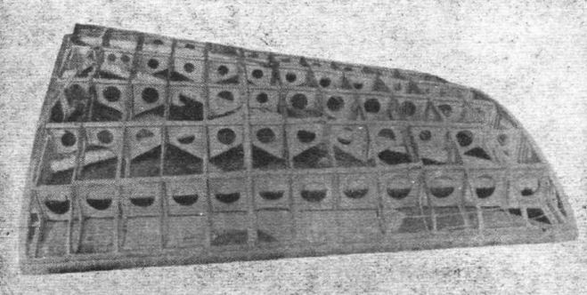
Fig. 1. - Centre section of lower main plane with three-ply surfacing removed.
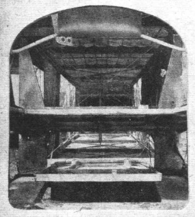
Fig. 20. - View looking down inside of fuselage from the main nacelle, showing trap-door and after-gunner's folding seat.
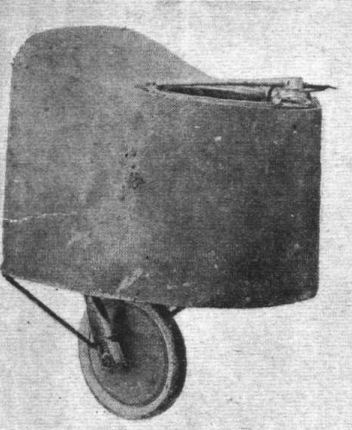
Fig. 22. - Front portion of the nacelle.
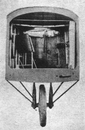
Fig. 23. - Inside of the front cockpit.
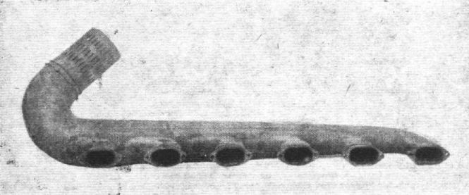
Fig. 30. - The exhaust pipe of the 260 h.p. Mercedes engine.
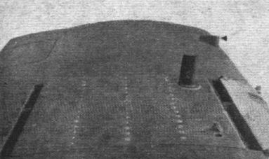
Fig. 37. - Gravity petrol tank let into the centre section of the upper plane. Its fabric cover is held down by press buttons. Note the detachable panel in the trailing edge of the plane.
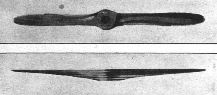
Figs. 40 and 41. - Front and side views of the propeller. Note the two additional bolt holes.
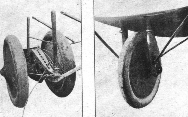
Fig. 46. - Main landing chassis with fabric fairing removed.
Fig. 47. - Landing wheel under the front portion of the nacelle.
Fig. 47. - Landing wheel under the front portion of the nacelle.
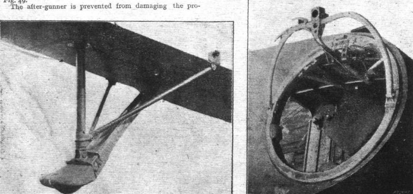
Fig. 48. - Tail skid.
Fig. 49. - Machine gun mounting in the front portion of the nacelle.
Fig. 49. - Machine gun mounting in the front portion of the nacelle.
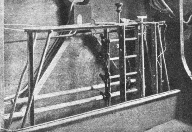
Fig. 54. - View of bomb-rack in nacelle. Behind it can be seen the spring of trimming gear.
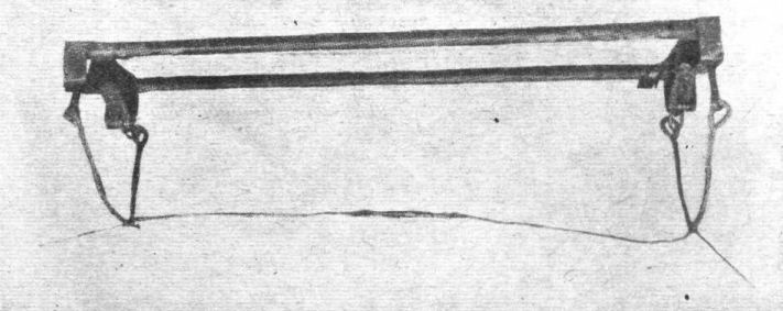
Fig. 55. - Large bomb-carrier.
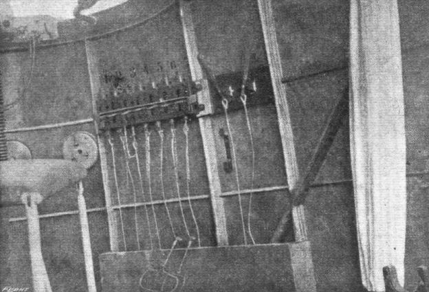
Fig. 56. - Bomb-release gear inside front cockpit.
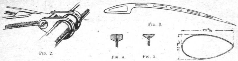
Fig. 2. Fig. 3. Fig. 4. Fig. 5. Fig. 6.
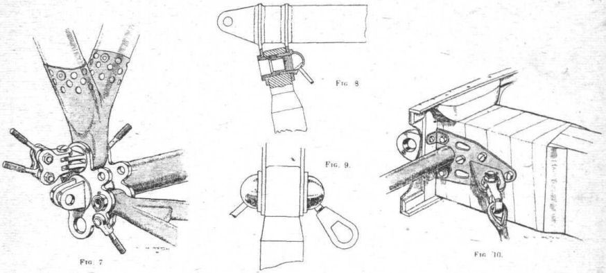
Fig. 7. Fig. 8. Fig. 9. Fig. 10.
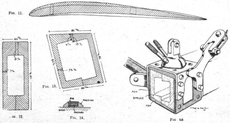
Fig. 11. Fig. 12. Fig. 13. Fig. 14. Fig. 15.
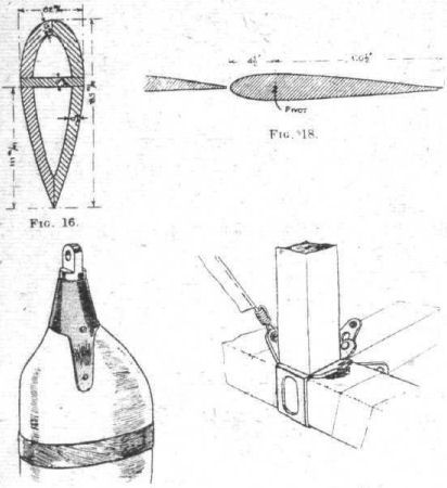
Fig. 16. Fig. 17. Fig. 18. Fig. 19.
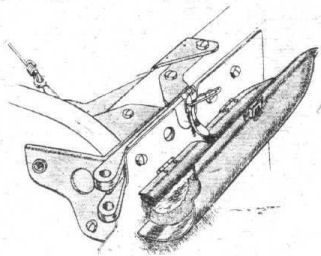
Fig. 21.
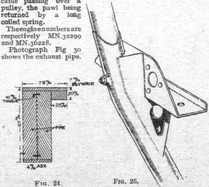
Fig. 24. Fig. 25.
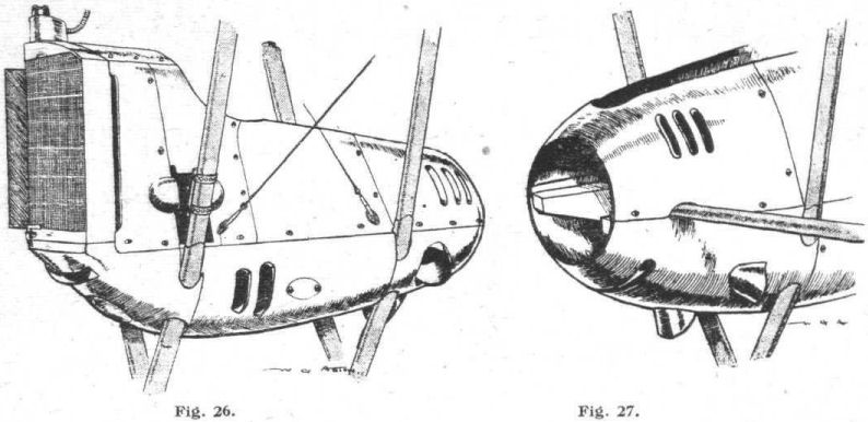
Fig. 26. Fig. 27.
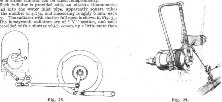
Fig. 28. Fig. 29.
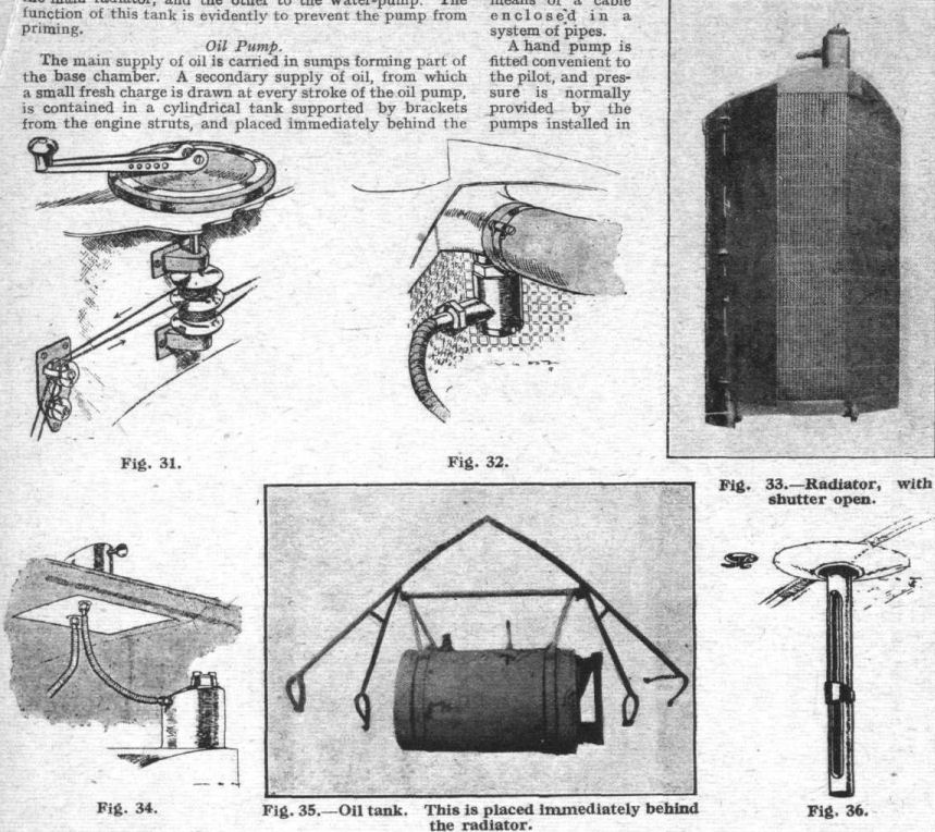
Fig. 31. Fig. 32.
Fig. 33. - Radiator, with shutter open.
Fig. 34.
Fig. 35. - Oil tank. This is placed Immediately behind the radiator.
Fig. 36.
Fig. 33. - Radiator, with shutter open.
Fig. 34.
Fig. 35. - Oil tank. This is placed Immediately behind the radiator.
Fig. 36.
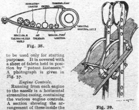
Fig. 38. Fig. 39.
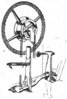
Fig. 42.

Fig. 43. Fig. 44.
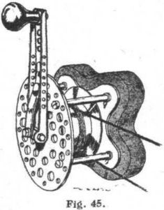
Fig. 45.
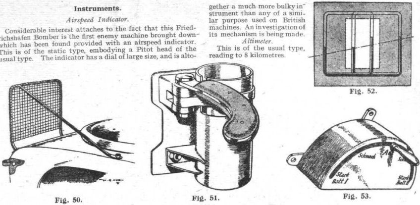
Fig. 50. Fig. 51. Fig. 52. Fig. 53.
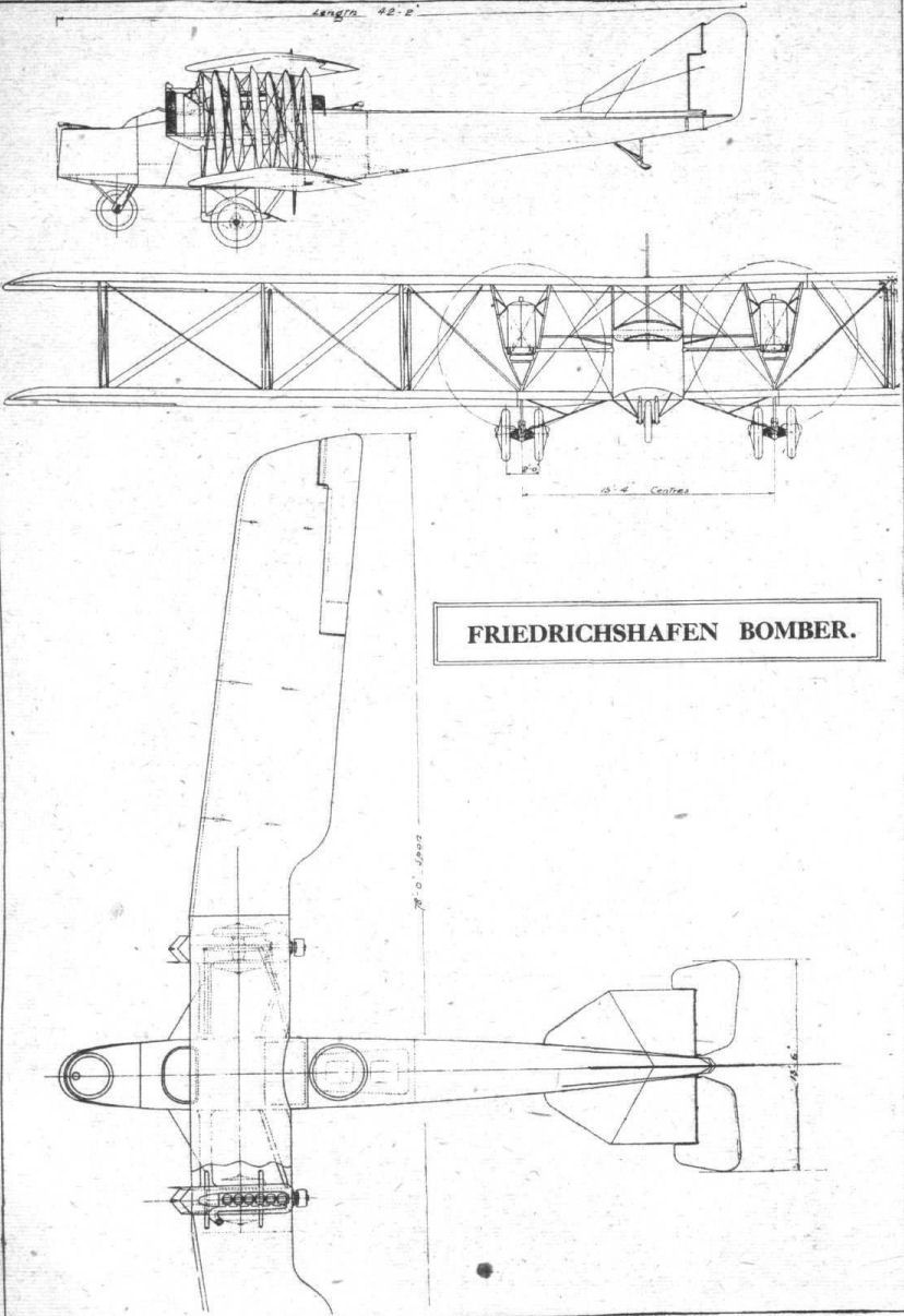
General arrangement drawings of the Friedrichshafen bomber.
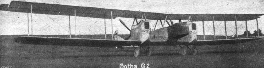
Three-quarter front view of the type G2 Gotha bomber.
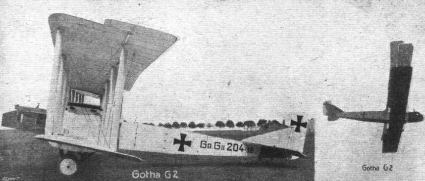
SIDE VIEW OF A GOTHA BOMBER. - This machine is one of the older type with four-wheeled undercarriage. In more recent machines of this make an additional pair of wheels has been added to each undercarriage. On the right the machine is seen in the air.
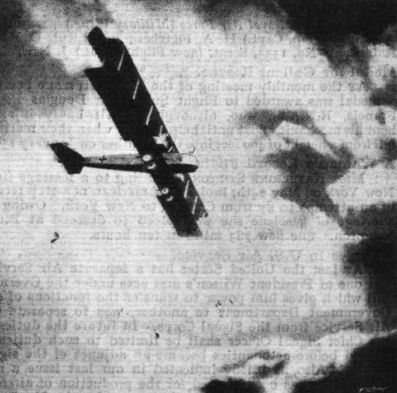
The moonlight raider.
Flight, November 14, 1918.
THE GOTHA BOMBER
WITH NOTES ON GIANT AEROPLANES
[Issued by Technical Department (Aircraft Production), Ministry of Munitions.]
THIS machine is now on view at the Enemy Aircraft View Room, Agricultural Hall, Islington. Passes can be obtained upon application to Ap. D. (L.), Pen Corner House, Kingsway, W.C.2.
The standard type of two-engine Gotha is a pusher, the appearance of which is characterised by the backward sweep of the main planes, which are also set at a lateral dihedral angle.
The set back of the planes is 4 deg., and the dihedral approximately 2 deg.
The following are the principal dimensions of the aeroplane, of which general arrangement drawings are given herewith :-
Maximum span 77 ft.
Span of lower plane 71 ft. 9 in.
Gap 7 ft.
Maximum chord 7 ft. 6 in.
Minimum chord 7 ft. 2 1/2 in.
Over-all length 41 ft.
Area of top plane 521.6 sq. ft.
Area of bottom plane 464 sq. ft.
Total area 985 sq. ft.
Area of upper aileron 32 sq. ft.
Area of balance of aileron 3.2 sq. ft.
Area of bottom aileron 22.4 sq. ft.
Span of tail planes 13 ft. 6 in.
Area of tail planes 45 sq. ft.
Area of rudder 16 sq. ft.
Area of rudder balance 3.2 sq. ft.
Area of elevators 19.2 sq. ft.
Area of fin 11.2 sq.ft.
Area of body
in horizontal plane 96 sq. ft.
Area of body
in vertical plane 107 sq. ft.
Weight empty 2,740 kg. = 6,039 lbs.
Useful load 1,235 kg. = 2,722 lbs.
Total weight fully loaded 3,975 kg. = 8,763 lbs.
Loading per sq. ft. 8.9 lbs.
Engines. Two 260 h.p. Mercedes.
Engine centres 14 ft.
Propeller diameter 10 ft. 2 in.
Track of main landing wheels 3 ft. 2 1/2 in.
Track of auxiliary landing wheels 2 ft. 7 1/2 in.
The speed of this machine at 12,000 ft. is estimated miles per hour.
Construction.
Wings. - The wings of this aeroplane are of wooden construction throughout, and have a section as shown in Fig. 1. This drawing also illustrates the construction of the rib (the web of which is of three-ply wood, extensively perforated, and the flange of solid wood grooved to fit upon the web, to which it is tacked).
For the purposes of comparison, the section of the R.A.F. 14 wing is super-imposed and drawn to the same scale. This is shown in broken lines.
The disposal of the spars is as follows :-
Leading edge to centre of leading spar, 9 in.
Centre of leading spar to centre of trailing spar, 4 ft. 4 in.
Centre of trailing spar to trailing edge, 2 ft. 5 in.
The space between the leading edge and the leading spar is covered as to the upper surface with three-ply, the rest of the wing being covered with fabric in the usual way.
The spars possess several points of interest, and their dimensions and method of construction are presented in Figs. 2 and 3, from which it will be seen that they differ from the practice adopted in other German designs.
The I Section main members are of spruce. The three-ply walls, applied to them by glueing and tacking, are principally birch, and are 4 mm. thick.
The spars are wrapped with fabric throughout.
In the earlier Gotha designs the sweep back of the wings was 10 deg. In the present design it is 4 deg., due probably to the fact that other means have been successfully adopted to get the centre of gravity sufficiently forward.
It will be seen from the scale drawings that whereas the upper wing surface consists of two portions which unite at the centre line of the machine, the lower plane on each side consists of the centre section attached to the base of the fuselage, and an outward extension, between which is interposed a short span of plane forming, with the engine bearers and their struts, and the landing carriages on each side, a completely independent and separate unit. These small sections of planes are covered in with three-ply, both top and bottom, and the same material is used for the upper surface of the centre section of the lower plane.
At the junction of the two upper wings, a rather unusual joint is employed; this is illustrated in Fig. 4, and consists of a series of rectangular staples which are held together by a steel wedge. The joints used in the lower plane are of a different character, and embody the usual pin principle, giving the spars, when not braced by the wiring, a hingeing action in the vertical plane. This joint is shown in Fig. 5, which also illustrates the manner in which the wings are braced against drag stresses by means of very light steel compression tubes and cables.
Another view of the box joint on the spar end is given in Fig. 5a, which shows its internal construction. Joints of the above design are used on either side of the engine bearer section.
Struts.
Apart from the struts which separate the engine eggs and brace them to the fuselage, there are three pairs of interplane struts on each wing. These struts are composed of steel tubing to which is attached a three-ply fairing. The design of the strut joint is shown in Fig. 6.
The wire bracing throughout is by multi-strand steel cable, the fitting of which, however, presents no features of interest.
Ailerons.
Only the upper ailerons are balanced, the upper and lower ailerons being connected by a single strut on each side. The operating lever is fitted on the top aileron, and works in a slot cut in, the upper main plane. From this lever wires are taken over pulleys on the leading spar of the lower plane, and thence to the fuselage through the space between the leading edge and the forward spar.
Where the wires pass through the small sections of lower plane under the engines, they are provided with detachable connections which can be inspected through hinged flaps.
The framework of the ailerons is of steel tube throughout, involving a welded-up one-piece construction.
Propeller Accommodation.
In order to permit the engine eggs to be placed sufficiently far forward to allow of the centre of gravity being correct, considerable inroads have had to be made in the trailing edge of both upper and lower planes in order to give scope for the propellers. In front of the screws, the chord of the planes is reduced to 5 ft. 9 in., and at this point the trailing edge is very blunt.
Empennage.
The whole of the empennage construction is of steel tubing, and the various components are rigidly braced together by inclined streamline struts, which, as in the case of the main struts, are of circular section steel tubing, to which a three-ply fairing has been added.
These external struts give the Gotha tail a somewhat clumsy appearance, and would seem furthermore to exercise a notable masking effect upon the rear gun. Only the rudder is balanced, and it will be noticed that the area of this organ, compared with that of the fin, is very large.
Fuselage.
The fuselage is in one piece from nose to rudder post, and is an entirely wooden construction, consisting of the usual longerons and wooden transverse members. It is covered in with three-ply throughout its length on the top, bottom and sides, but whereas in most German aeroplanes the three-ply lining is relied upon for solidifying the structure, in this machine it is extensively reinforced by diagonal wire bracings, especially in the forward portion of the fuselage at the point at which the main planes are attached.
In the extreme front is placed the front gunner's cockpit. Immediately behind him, and on the left-hand side of the machine, sits the pilot; beside him is a folding seat for another passenger.
Between the pilot's seat and the rear gunner's cockpit are placed the two main petrol tanks, which occupy the full width of the fuselage.
The original intention of the designer was evidently to fit tanks of smaller capacity, shaped in such a way as to provide a communication tunnel between the pilot's seat and the rear gunner's cockpit. For this purpose the wooden bulkheads on each end of the tank space are deeply cut away on the left-hand side. With the existing arrangement of tanks, however, no interchange of personnel is possible.
Another small point of interest is the inclination of the back of the pilot's seat; for this purpose careful consideration of space has resulted in a wedge-shaped piece being let into the forward tank, indicating again that all possible means have been adopted to get the C.G. sufficiently forward.
The rear tank is of identical construction, and also possesses this wedge-shaped arrangement. In this case, however, the wedge-shaped piece represents waste of space.
The rear gunner's cockpit is roomy and provided with a folding seat. Abaft of it, the fuselage is furnished with an elaborate gun tunnel, which, however, differs very markedly from that which was incorporated in the earlier Gotha designs, in which tine fuselage was completely covered in as to its top surface, and the tunnel was only used for a gun mounted on the floor of the cockpit. In the present design, the tunnel is furnished with a V-shaped opening in the upper surface, so that the gun mounted on the top of the fuselage can fire backwards and downwards through an arc of about 25 deg. laterally and about 60 deg. vertically. This is shown in Fig. 7.
The inside of this tunnel is lined with three-ply wood, and its arrangement is clearly shown in Fig. 8. On the floor of the fuselage, in the rear gunner's cockpit, a mount is provided for a second gun, but in none of the Gotha machines brought down was a gun fitted at this point.
It is noted that to give the rear gunner a greater feeling of security, and to prevent any loose articles from falling out, wooden cross pieces are fitted up immediately in front of the tunnel opening. At the forward end of the tunnel the fuselage is evidently weak, as it was at this point that breakage occurred in most of the machines brought down.
Fig. 9 illustrates one of the brackets by means of which the fuselage is secured to the upper main plane; it carries a short stream-lined strut. It will be noticed that the characteristic German dome-shaped clip is used, but that in this case the usual welded joint is replaced by rivets. This bracket occurs at the after bulkhead immediately behind the rear petrol tank; the dotted lines proceeding from the small clip indicate how this bulkhead is cut away so as to provide, in the original scheme, an opening through which the personnel could squeeze in order to change places if necessary.
(To be continued.)
Flight, November 21, 1918.
THE GOTHA BOMBER
WITH NOTES ON GIANT AEROPLANES
[Issued by Technical Department (Aircraft Production), Ministry of Munitions.)
(Continued from page 1282.)
Undercarriage
THE undercarriages on each side form, with the engine mountings and a small section of the lower main plane, completely independent units. There is no landing wheel under the nose of the machine as is the case in the Friedrichshafen design. Each -undercarriage has four wheels. The larger pair are attached to an axle placed immediately under the centre of the chord of the main planes, which point may be assumed to approach very closely the centre of gravity. This axle, as shown in the detail sketches reproduced herewith, moves up and down in guides against the action of two long compression springs concealed within the main undercarriage struts. A stout steel cable is passed over the axle and under two pulleys enclosed in the horn plate; thence it goes up inside the long springs to the heads of adjustable bolts, against which the upper ends of the springs abut. The axle is fitted with a large three-ply fairing attached by means of light straps, and at its outer end terminates in a tee piece, which slides up and down in a slot in the horn plate, and prevents the axle from turning round.
Only the front undercarriage strut is streamlined. It is stayed with a tube to the middle of the rear strut, and a t this point the mudguard brackets are fitted.
The front pair of landing wheels, the fitting of which is to facilitate landing in the dark, are supported on an axle attached to the frame extension by bands of steel coil springs of the type usually found in the smaller German designs.
The front wheels are smaller in diameter and narrower in track than the main landing wheels.
In every case the forward extension of the undercarriage was very badly crumpled up, and it is noticeably light in construction compared with the massive main landing gear.
As might be expected, a very stout tail skid is fitted. This is shown in detail in Fig. 11.
The hinged skid is very strongly stayed in all directions. At its upper end it is attached with loops of steel coil springs to two tubular steel rings clipped to either side of the fuselage. A steel cable limits the distance through which the tail skid can move.
The body of the tail skid is of wood, but it is heavily rein forced with a steel shoe and with a steel front edge. Fig. 11 also shows the attachment of the lower tail struts to the bottom of the fuselage, and it will be seen that these are provided with sharp bars to discourage mechanics from lifting the tail by their means.
Engine Mounting
The 260 h.p. six-cylinder Mercedes engines are carried on bearers arranged as shown in the drawing of the undercarriage, and illustrated with more detail in Fig. 13.
The bearers themselves are of wood, and between the main vertical supports on which they rest are of the section shown in Fig. 14. They are attached to these main supports by ball joints of large diameter, and the struts are stream-lined with casings of thin metal. These are shown in Fig. 15.
At their rear ends the engine bearers are united by a curved cross piece of hollow section, built up of sheet steel riveted together. (Fig. 16.)
The engine bearers are triangulated to the plane section below them by cross wires as shown in Fig. 13, and also by diagonal steel tubes, the latter being attached by feet of the type shown in Fig. 17.
The bracket supporting the bearers in front entirely surrounds them, and at is upper end is provided with an attachment for the strut which unites the engine mounting to the top plane spar, and also with a ball and socket attachment for the undercarriage bracing cables.
At the bottom of the forward engine bearer support is attached one of the diagonal strengthening members of the forward undercarriage framework.
Engines
In general the engines show no departures from the usual Mercedes practice, but there are a few points which are worth of note.
Two different kinds of radiators were employed on machines otherwise exactly similar, the principal difference between these radiators being the arrangement of the shutters; in one case a series of vertical panels is used, and in the other a simple sliding door is adapted to be raised or lowered so as to shield the radiator surface to the required degree.
Electrical thermometers of the usual pattern are fitted.
The radiator controls are placed one on each side of the pilot's cockpit, and are illustrated in Fig. 20.
Five different positions of the lever are provided for, and it works the shutters through return cables passing over a large aluminium pulley.
Two different kinds of silencer were found; the type illustrated in Fig. 21 is similar to that used on previous Gothas, and also on the Friedrichshafen machines. It consists of a sheet steel manifold of very light construction, containing no baffles or other means of restricting the outflow of gas.
The other type of exhaust box is shown in Fig. 22, and in this case it would appear that some attempt has been made not only to silence the exhaust, but also to prevent the aeroplane showing its whereabouts through the exhaust flames.
This new type of silencer has been reported upon as follows :-
The exhaust manifold has been altered in the spacing of the communications in order to fit a B.H.P. engine in a D.H. 9. The manifold consists of a cylinder 3 ft. 9 ins. long and 6 ins. in diameter; pointed nose and tail pieces are welded on, and 14 cooling fins running lengthwise are fitted. Between the fins a number of 1/4-in. diameter holes are drilled, forming a means of outlet for the exhaust gases, no baffle plates being fitted; the whole is made up of 20-gauge sheet steel, and is very flimsy in appearance.
For testing this exhaust as a flame damper, a machine fitted with the manifold was flown at night with no navigation lights, and another machine was sent up to find it. As a silencer the manifold reduces the distance at which the machine is audible by a mean of about 4 per cent. No difficulty was experienced by the observing pilot in picking up the machine: although the flame usually seen at night was broken up, there was a stream of small sparks which made the aeroplane just as visible. In addition, it was noticed that the manifold became red hot when the machine was flown at full throttle.
Controls
All the Gotha machines brought down were fitted with the same type of control, though certain detail differences are noticed.
The ailerons are worked by a large diameter wheel by means of a chain and sprocket as shown in Fig. 23.
Limiting cables are fitted and attached to an adjustable clip on the column.
The wires are passed over pulleys, and issue through the ends of the transverse rocking shaft, whence they pass through the planes between the leading edge and the leading spar of the lower wings.
At the extreme outer interplane strut they are taken over pulleys to the levers of the upper ailerons, which are connected to those of the lower ailerons by a light streamline strut. The horizontal rocking shaft extends through the side of the fuselage, and is there fitted in some cases with the simple form of double - ended crank shown in Fig. 23, but in others with the quadrant type of lever built up of steel tube, and illustrated in Fig. 24.
The elevator and rudder wires are led along the outside of the fuselage through guides.
The control wires for the elevator are duplicated, and in the case of the rudder a double crank is fitted on the rudder post. This is shown in Fig. 25.
The rudder control bar is of the usual welded-up steel type, and is fitted with spring controlled heel rests. It is fitted with a grooved quadrant carrying the wires which pass over pulleys mounted in brackets on the inside of the fuselage walls. The rudder bar is shown incidentally in Fig. 27. No form of dual control is fitted. It is, however, of interest to note that whereas in the Friedrichshafen design means are provided both for adjusting the trim of the tail and for locking the controls in any desired position, the Gotha machine possesses neither of these refinements.
Engine Controls
The throttle levers are fitted on the left-hand side of the pilot's seat, which is also on the left-hand side of the fuselage. This control consists of two mallet-headed levers, which are shaped so as to be conveniently worked either together or separately; the cranks and rods which they operate are placed outside the main section of the fuselage, and are covered in with a streamline metal casing.
The engines are fitted, as is the usual Mercedes practice, with combination ignition and throttle controls; the function of the ball-headed third lever is not precisely known.
In front of the pilot is a dashboard arranged as shown in Fig. 27, containing the usual switches, gauges, instruments and control taps. One of the latter is shown in more detail in Fig. 28.
Petrol System
The two main petrol tanks carried in the forward position of the fuselage are equal in size, and have a joint capacity of 175 gallons. They are made of sheet brass, and appear to be well provided with internal baffle plates.
On the left-hand upper wing, slightly to one side of the centre line of the machine, is a streamline gravity tank, strapped on to the upper surface, above which it projects; this gravity tank, which is used solely for starting purposes, has a capacity of about 10 gallons. It is filled from one or other of the main tanks by means of a hand-operated suction pump mounted on the right-hand side of the pilot's dash board, as shown in Fig. 27.
The two main tanks work under pressure; an air pump of the usual type is mounted within reach of the pilot.
Armament
Two Parabellum guns are carried - one in the forward cockpit, and one in the rear. The former is carried on a large ring mounting, which is shown in Figs. 29 and 30. In order to allow access between this cockpit and that of the pilot, part of the ring is made to hinge out of the way like the flap of a counter. The ring is extensively perforated with countersunk holes, apparently for lightening purposes. The holes of the hinged portion, together with the latch which secures them, are shown in Fig. 31. The gun is carried on a universally jointed bracket of the accepted design, which is furnished with an inclined extension, supported from the floor of the fuselage by a foot step bearing.
The gun carrier is fitted with two steel rollers, which rest on the ring mounting, outside of which is mounted a gallery of light metal fitted with numerous holes for the reception of Very pistol ammunition.
The rear gun is carried on a forked bracket, which slides over two rails made of bent steel tube, and mounted on the top surface of the fuselage as illustrated in Fig. 7. This gun carriage has a very limited arc of motion, and the usual expanded metal shields are fitted to prevent the gunner firing at the propeller, and possibly to prevent him leaning out far enough to be in danger of being struck by one of the blades.
On the floor of the gunner's cockpit and close to the edge of the tunnel is a bracket designed for the reception of a second gun which would fire in a similar manner to that which was fitted on the earlier Gotha types. No guns fixed in this position have been found, and it is evident, therefore that the upper gun is relied upon to answer all defensive requirements.
Bombs
The number and type of bombs carried on Gotha aeroplanes varies considerably, and the carriers are in consequence adapted to be easily removed and replaced by others of larger or smaller size, as the case may be.
The carriers used on the Gotha are exactly similar to those which have been found on A.E.G. and Friedrichshafen machines and present no new features, with this exception that on the Gotha each carrier is furnished with an electrical detector device which informs the bomber that the projectile has actually left the carrier. This detector consists of a small switch, details of which are shown in Figs. 32 and 33, so that when the bomb leaves the carrier an electric lamp is illuminated inside the forward cockpit; this is carried out by means of a small spring-operated plunger switch.
As a rule, eight bombs, each of 100 kg. weight, are carried - two being supported directly under the fuselage, and three on either side of the bottom plane centre section. Their release is effected by six small levers working the release gear through wires; each of these levers is painted a characteristic colour, and they are furthermore of different lengths, so that the bomber has no difficulty in pulling the right one. It would appear that each bomb carried on the centre section of the lower plane is released separately and that probably the two bombs underneath the fuselage are discharged simultaneously. The levers are shown at the back of Fig. 34, which also illustrates the folding seat and the communication flap between the bomber's cockpit and that of the pilot. Both the forward cockpits are furnished with large celluloid windows, which have been blacked over in all cases so as to be opaque.
Wireless
The machine is internally wired throughout for giving greater wireless capacity, and the dynamo for the system is driven direct by one of the engines. It also furnishes current for the heating of passengers' clothing, for which plugs are arranged at convenient points.
It will be noted in Fig. 34 that the floor in the corner of the cockpit is dished for the reception of the apparatus which carries the bobbin and the aerial wire.
Instruments
The usual array of engine revolution counters, thermometers, pressure gauges, &c, is fitted on the Gotha, but no new types were found.
Fabric and Dope
Both the fabric and dope on the Gotha aeroplanes conform to the usual German standard. The camouflage is similar to that of the Friedrichshafen, and consists of irregular polygons of various dark colours, which are printed on the fabric.
Gotha brought down by French A.A. Fire near Crochte, on July 4th-5th, 1918.
The general construction of this machine appears to be similar to that described above in most respects, except for three modifications, which are worthy of note :-
1. A biplane tail unit. This is illustrated in the photographs, Figs. 38, 39 and 40. It is similar in design to that of the Handley-Page, and embodies two fins on either side of the fuselage between the planes of the tail. The rudders are hinged to the trailing edges of these fins. The measurements of the tail unit are as follows :-
Top elevator span 5 ft. 7 in.
Top elevator chord 2 ft. 7 in.
Bottom elevator span 5 ft. 3 in.
Bottom elevator chord 1 ft. 6 1/2 in.
Balance piece 11 1/2 in. by 10 3/4 in.
Gap 2 ft. 9 1/2 in.
Bottom tail planes each average fore and aft measurement 2 ft. 5 in.
Span along trailing edge, each 4 ft. 2 in.
Top tail plane, average fore and aft measurement 2 ft. 5 in.
Span along trailing edge 8 ft. 10 in.
This tail unit would appear to have been adapted in order to give the after gunner a better chance of attacking chasing aeroplanes, as the span is considerably smaller than that of the monoplane tail. It is constructed throughout of steel tubing.
2. Extensions are fitted to the top ailerons as shown in the attached diagram (Fig. 35); it would appear from these that the lateral control of the Gotha has been found insufficient.
3. The undercarriages are arranged in a similar manner to those of the Friedrichshafen, that is to say, there is a two-wheeled undercarriage underneath each engine, and a third two-wheeled axle mounted on to the fore part of the fuselage; the wheels throughout are of equal size, carrying 810 by 125 mm. tyres.
Some details of the tail control are given in Figs. 36 and 37, from which it will be seen that double-ended levers with tubular tie rods are adopted for the rudders.
(To be continued.)
THE GOTHA BOMBER
WITH NOTES ON GIANT AEROPLANES
[Issued by Technical Department (Aircraft Production), Ministry of Munitions.]
THIS machine is now on view at the Enemy Aircraft View Room, Agricultural Hall, Islington. Passes can be obtained upon application to Ap. D. (L.), Pen Corner House, Kingsway, W.C.2.
The standard type of two-engine Gotha is a pusher, the appearance of which is characterised by the backward sweep of the main planes, which are also set at a lateral dihedral angle.
The set back of the planes is 4 deg., and the dihedral approximately 2 deg.
The following are the principal dimensions of the aeroplane, of which general arrangement drawings are given herewith :-
Maximum span 77 ft.
Span of lower plane 71 ft. 9 in.
Gap 7 ft.
Maximum chord 7 ft. 6 in.
Minimum chord 7 ft. 2 1/2 in.
Over-all length 41 ft.
Area of top plane 521.6 sq. ft.
Area of bottom plane 464 sq. ft.
Total area 985 sq. ft.
Area of upper aileron 32 sq. ft.
Area of balance of aileron 3.2 sq. ft.
Area of bottom aileron 22.4 sq. ft.
Span of tail planes 13 ft. 6 in.
Area of tail planes 45 sq. ft.
Area of rudder 16 sq. ft.
Area of rudder balance 3.2 sq. ft.
Area of elevators 19.2 sq. ft.
Area of fin 11.2 sq.ft.
Area of body
in horizontal plane 96 sq. ft.
Area of body
in vertical plane 107 sq. ft.
Weight empty 2,740 kg. = 6,039 lbs.
Useful load 1,235 kg. = 2,722 lbs.
Total weight fully loaded 3,975 kg. = 8,763 lbs.
Loading per sq. ft. 8.9 lbs.
Engines. Two 260 h.p. Mercedes.
Engine centres 14 ft.
Propeller diameter 10 ft. 2 in.
Track of main landing wheels 3 ft. 2 1/2 in.
Track of auxiliary landing wheels 2 ft. 7 1/2 in.
The speed of this machine at 12,000 ft. is estimated miles per hour.
Construction.
Wings. - The wings of this aeroplane are of wooden construction throughout, and have a section as shown in Fig. 1. This drawing also illustrates the construction of the rib (the web of which is of three-ply wood, extensively perforated, and the flange of solid wood grooved to fit upon the web, to which it is tacked).
For the purposes of comparison, the section of the R.A.F. 14 wing is super-imposed and drawn to the same scale. This is shown in broken lines.
The disposal of the spars is as follows :-
Leading edge to centre of leading spar, 9 in.
Centre of leading spar to centre of trailing spar, 4 ft. 4 in.
Centre of trailing spar to trailing edge, 2 ft. 5 in.
The space between the leading edge and the leading spar is covered as to the upper surface with three-ply, the rest of the wing being covered with fabric in the usual way.
The spars possess several points of interest, and their dimensions and method of construction are presented in Figs. 2 and 3, from which it will be seen that they differ from the practice adopted in other German designs.
The I Section main members are of spruce. The three-ply walls, applied to them by glueing and tacking, are principally birch, and are 4 mm. thick.
The spars are wrapped with fabric throughout.
In the earlier Gotha designs the sweep back of the wings was 10 deg. In the present design it is 4 deg., due probably to the fact that other means have been successfully adopted to get the centre of gravity sufficiently forward.
It will be seen from the scale drawings that whereas the upper wing surface consists of two portions which unite at the centre line of the machine, the lower plane on each side consists of the centre section attached to the base of the fuselage, and an outward extension, between which is interposed a short span of plane forming, with the engine bearers and their struts, and the landing carriages on each side, a completely independent and separate unit. These small sections of planes are covered in with three-ply, both top and bottom, and the same material is used for the upper surface of the centre section of the lower plane.
At the junction of the two upper wings, a rather unusual joint is employed; this is illustrated in Fig. 4, and consists of a series of rectangular staples which are held together by a steel wedge. The joints used in the lower plane are of a different character, and embody the usual pin principle, giving the spars, when not braced by the wiring, a hingeing action in the vertical plane. This joint is shown in Fig. 5, which also illustrates the manner in which the wings are braced against drag stresses by means of very light steel compression tubes and cables.
Another view of the box joint on the spar end is given in Fig. 5a, which shows its internal construction. Joints of the above design are used on either side of the engine bearer section.
Struts.
Apart from the struts which separate the engine eggs and brace them to the fuselage, there are three pairs of interplane struts on each wing. These struts are composed of steel tubing to which is attached a three-ply fairing. The design of the strut joint is shown in Fig. 6.
The wire bracing throughout is by multi-strand steel cable, the fitting of which, however, presents no features of interest.
Ailerons.
Only the upper ailerons are balanced, the upper and lower ailerons being connected by a single strut on each side. The operating lever is fitted on the top aileron, and works in a slot cut in, the upper main plane. From this lever wires are taken over pulleys on the leading spar of the lower plane, and thence to the fuselage through the space between the leading edge and the forward spar.
Where the wires pass through the small sections of lower plane under the engines, they are provided with detachable connections which can be inspected through hinged flaps.
The framework of the ailerons is of steel tube throughout, involving a welded-up one-piece construction.
Propeller Accommodation.
In order to permit the engine eggs to be placed sufficiently far forward to allow of the centre of gravity being correct, considerable inroads have had to be made in the trailing edge of both upper and lower planes in order to give scope for the propellers. In front of the screws, the chord of the planes is reduced to 5 ft. 9 in., and at this point the trailing edge is very blunt.
Empennage.
The whole of the empennage construction is of steel tubing, and the various components are rigidly braced together by inclined streamline struts, which, as in the case of the main struts, are of circular section steel tubing, to which a three-ply fairing has been added.
These external struts give the Gotha tail a somewhat clumsy appearance, and would seem furthermore to exercise a notable masking effect upon the rear gun. Only the rudder is balanced, and it will be noticed that the area of this organ, compared with that of the fin, is very large.
Fuselage.
The fuselage is in one piece from nose to rudder post, and is an entirely wooden construction, consisting of the usual longerons and wooden transverse members. It is covered in with three-ply throughout its length on the top, bottom and sides, but whereas in most German aeroplanes the three-ply lining is relied upon for solidifying the structure, in this machine it is extensively reinforced by diagonal wire bracings, especially in the forward portion of the fuselage at the point at which the main planes are attached.
In the extreme front is placed the front gunner's cockpit. Immediately behind him, and on the left-hand side of the machine, sits the pilot; beside him is a folding seat for another passenger.
Between the pilot's seat and the rear gunner's cockpit are placed the two main petrol tanks, which occupy the full width of the fuselage.
The original intention of the designer was evidently to fit tanks of smaller capacity, shaped in such a way as to provide a communication tunnel between the pilot's seat and the rear gunner's cockpit. For this purpose the wooden bulkheads on each end of the tank space are deeply cut away on the left-hand side. With the existing arrangement of tanks, however, no interchange of personnel is possible.
Another small point of interest is the inclination of the back of the pilot's seat; for this purpose careful consideration of space has resulted in a wedge-shaped piece being let into the forward tank, indicating again that all possible means have been adopted to get the C.G. sufficiently forward.
The rear tank is of identical construction, and also possesses this wedge-shaped arrangement. In this case, however, the wedge-shaped piece represents waste of space.
The rear gunner's cockpit is roomy and provided with a folding seat. Abaft of it, the fuselage is furnished with an elaborate gun tunnel, which, however, differs very markedly from that which was incorporated in the earlier Gotha designs, in which tine fuselage was completely covered in as to its top surface, and the tunnel was only used for a gun mounted on the floor of the cockpit. In the present design, the tunnel is furnished with a V-shaped opening in the upper surface, so that the gun mounted on the top of the fuselage can fire backwards and downwards through an arc of about 25 deg. laterally and about 60 deg. vertically. This is shown in Fig. 7.
The inside of this tunnel is lined with three-ply wood, and its arrangement is clearly shown in Fig. 8. On the floor of the fuselage, in the rear gunner's cockpit, a mount is provided for a second gun, but in none of the Gotha machines brought down was a gun fitted at this point.
It is noted that to give the rear gunner a greater feeling of security, and to prevent any loose articles from falling out, wooden cross pieces are fitted up immediately in front of the tunnel opening. At the forward end of the tunnel the fuselage is evidently weak, as it was at this point that breakage occurred in most of the machines brought down.
Fig. 9 illustrates one of the brackets by means of which the fuselage is secured to the upper main plane; it carries a short stream-lined strut. It will be noticed that the characteristic German dome-shaped clip is used, but that in this case the usual welded joint is replaced by rivets. This bracket occurs at the after bulkhead immediately behind the rear petrol tank; the dotted lines proceeding from the small clip indicate how this bulkhead is cut away so as to provide, in the original scheme, an opening through which the personnel could squeeze in order to change places if necessary.
(To be continued.)
Flight, November 21, 1918.
THE GOTHA BOMBER
WITH NOTES ON GIANT AEROPLANES
[Issued by Technical Department (Aircraft Production), Ministry of Munitions.)
(Continued from page 1282.)
Undercarriage
THE undercarriages on each side form, with the engine mountings and a small section of the lower main plane, completely independent units. There is no landing wheel under the nose of the machine as is the case in the Friedrichshafen design. Each -undercarriage has four wheels. The larger pair are attached to an axle placed immediately under the centre of the chord of the main planes, which point may be assumed to approach very closely the centre of gravity. This axle, as shown in the detail sketches reproduced herewith, moves up and down in guides against the action of two long compression springs concealed within the main undercarriage struts. A stout steel cable is passed over the axle and under two pulleys enclosed in the horn plate; thence it goes up inside the long springs to the heads of adjustable bolts, against which the upper ends of the springs abut. The axle is fitted with a large three-ply fairing attached by means of light straps, and at its outer end terminates in a tee piece, which slides up and down in a slot in the horn plate, and prevents the axle from turning round.
Only the front undercarriage strut is streamlined. It is stayed with a tube to the middle of the rear strut, and a t this point the mudguard brackets are fitted.
The front pair of landing wheels, the fitting of which is to facilitate landing in the dark, are supported on an axle attached to the frame extension by bands of steel coil springs of the type usually found in the smaller German designs.
The front wheels are smaller in diameter and narrower in track than the main landing wheels.
In every case the forward extension of the undercarriage was very badly crumpled up, and it is noticeably light in construction compared with the massive main landing gear.
As might be expected, a very stout tail skid is fitted. This is shown in detail in Fig. 11.
The hinged skid is very strongly stayed in all directions. At its upper end it is attached with loops of steel coil springs to two tubular steel rings clipped to either side of the fuselage. A steel cable limits the distance through which the tail skid can move.
The body of the tail skid is of wood, but it is heavily rein forced with a steel shoe and with a steel front edge. Fig. 11 also shows the attachment of the lower tail struts to the bottom of the fuselage, and it will be seen that these are provided with sharp bars to discourage mechanics from lifting the tail by their means.
Engine Mounting
The 260 h.p. six-cylinder Mercedes engines are carried on bearers arranged as shown in the drawing of the undercarriage, and illustrated with more detail in Fig. 13.
The bearers themselves are of wood, and between the main vertical supports on which they rest are of the section shown in Fig. 14. They are attached to these main supports by ball joints of large diameter, and the struts are stream-lined with casings of thin metal. These are shown in Fig. 15.
At their rear ends the engine bearers are united by a curved cross piece of hollow section, built up of sheet steel riveted together. (Fig. 16.)
The engine bearers are triangulated to the plane section below them by cross wires as shown in Fig. 13, and also by diagonal steel tubes, the latter being attached by feet of the type shown in Fig. 17.
The bracket supporting the bearers in front entirely surrounds them, and at is upper end is provided with an attachment for the strut which unites the engine mounting to the top plane spar, and also with a ball and socket attachment for the undercarriage bracing cables.
At the bottom of the forward engine bearer support is attached one of the diagonal strengthening members of the forward undercarriage framework.
Engines
In general the engines show no departures from the usual Mercedes practice, but there are a few points which are worth of note.
Two different kinds of radiators were employed on machines otherwise exactly similar, the principal difference between these radiators being the arrangement of the shutters; in one case a series of vertical panels is used, and in the other a simple sliding door is adapted to be raised or lowered so as to shield the radiator surface to the required degree.
Electrical thermometers of the usual pattern are fitted.
The radiator controls are placed one on each side of the pilot's cockpit, and are illustrated in Fig. 20.
Five different positions of the lever are provided for, and it works the shutters through return cables passing over a large aluminium pulley.
Two different kinds of silencer were found; the type illustrated in Fig. 21 is similar to that used on previous Gothas, and also on the Friedrichshafen machines. It consists of a sheet steel manifold of very light construction, containing no baffles or other means of restricting the outflow of gas.
The other type of exhaust box is shown in Fig. 22, and in this case it would appear that some attempt has been made not only to silence the exhaust, but also to prevent the aeroplane showing its whereabouts through the exhaust flames.
This new type of silencer has been reported upon as follows :-
The exhaust manifold has been altered in the spacing of the communications in order to fit a B.H.P. engine in a D.H. 9. The manifold consists of a cylinder 3 ft. 9 ins. long and 6 ins. in diameter; pointed nose and tail pieces are welded on, and 14 cooling fins running lengthwise are fitted. Between the fins a number of 1/4-in. diameter holes are drilled, forming a means of outlet for the exhaust gases, no baffle plates being fitted; the whole is made up of 20-gauge sheet steel, and is very flimsy in appearance.
For testing this exhaust as a flame damper, a machine fitted with the manifold was flown at night with no navigation lights, and another machine was sent up to find it. As a silencer the manifold reduces the distance at which the machine is audible by a mean of about 4 per cent. No difficulty was experienced by the observing pilot in picking up the machine: although the flame usually seen at night was broken up, there was a stream of small sparks which made the aeroplane just as visible. In addition, it was noticed that the manifold became red hot when the machine was flown at full throttle.
Controls
All the Gotha machines brought down were fitted with the same type of control, though certain detail differences are noticed.
The ailerons are worked by a large diameter wheel by means of a chain and sprocket as shown in Fig. 23.
Limiting cables are fitted and attached to an adjustable clip on the column.
The wires are passed over pulleys, and issue through the ends of the transverse rocking shaft, whence they pass through the planes between the leading edge and the leading spar of the lower wings.
At the extreme outer interplane strut they are taken over pulleys to the levers of the upper ailerons, which are connected to those of the lower ailerons by a light streamline strut. The horizontal rocking shaft extends through the side of the fuselage, and is there fitted in some cases with the simple form of double - ended crank shown in Fig. 23, but in others with the quadrant type of lever built up of steel tube, and illustrated in Fig. 24.
The elevator and rudder wires are led along the outside of the fuselage through guides.
The control wires for the elevator are duplicated, and in the case of the rudder a double crank is fitted on the rudder post. This is shown in Fig. 25.
The rudder control bar is of the usual welded-up steel type, and is fitted with spring controlled heel rests. It is fitted with a grooved quadrant carrying the wires which pass over pulleys mounted in brackets on the inside of the fuselage walls. The rudder bar is shown incidentally in Fig. 27. No form of dual control is fitted. It is, however, of interest to note that whereas in the Friedrichshafen design means are provided both for adjusting the trim of the tail and for locking the controls in any desired position, the Gotha machine possesses neither of these refinements.
Engine Controls
The throttle levers are fitted on the left-hand side of the pilot's seat, which is also on the left-hand side of the fuselage. This control consists of two mallet-headed levers, which are shaped so as to be conveniently worked either together or separately; the cranks and rods which they operate are placed outside the main section of the fuselage, and are covered in with a streamline metal casing.
The engines are fitted, as is the usual Mercedes practice, with combination ignition and throttle controls; the function of the ball-headed third lever is not precisely known.
In front of the pilot is a dashboard arranged as shown in Fig. 27, containing the usual switches, gauges, instruments and control taps. One of the latter is shown in more detail in Fig. 28.
Petrol System
The two main petrol tanks carried in the forward position of the fuselage are equal in size, and have a joint capacity of 175 gallons. They are made of sheet brass, and appear to be well provided with internal baffle plates.
On the left-hand upper wing, slightly to one side of the centre line of the machine, is a streamline gravity tank, strapped on to the upper surface, above which it projects; this gravity tank, which is used solely for starting purposes, has a capacity of about 10 gallons. It is filled from one or other of the main tanks by means of a hand-operated suction pump mounted on the right-hand side of the pilot's dash board, as shown in Fig. 27.
The two main tanks work under pressure; an air pump of the usual type is mounted within reach of the pilot.
Armament
Two Parabellum guns are carried - one in the forward cockpit, and one in the rear. The former is carried on a large ring mounting, which is shown in Figs. 29 and 30. In order to allow access between this cockpit and that of the pilot, part of the ring is made to hinge out of the way like the flap of a counter. The ring is extensively perforated with countersunk holes, apparently for lightening purposes. The holes of the hinged portion, together with the latch which secures them, are shown in Fig. 31. The gun is carried on a universally jointed bracket of the accepted design, which is furnished with an inclined extension, supported from the floor of the fuselage by a foot step bearing.
The gun carrier is fitted with two steel rollers, which rest on the ring mounting, outside of which is mounted a gallery of light metal fitted with numerous holes for the reception of Very pistol ammunition.
The rear gun is carried on a forked bracket, which slides over two rails made of bent steel tube, and mounted on the top surface of the fuselage as illustrated in Fig. 7. This gun carriage has a very limited arc of motion, and the usual expanded metal shields are fitted to prevent the gunner firing at the propeller, and possibly to prevent him leaning out far enough to be in danger of being struck by one of the blades.
On the floor of the gunner's cockpit and close to the edge of the tunnel is a bracket designed for the reception of a second gun which would fire in a similar manner to that which was fitted on the earlier Gotha types. No guns fixed in this position have been found, and it is evident, therefore that the upper gun is relied upon to answer all defensive requirements.
Bombs
The number and type of bombs carried on Gotha aeroplanes varies considerably, and the carriers are in consequence adapted to be easily removed and replaced by others of larger or smaller size, as the case may be.
The carriers used on the Gotha are exactly similar to those which have been found on A.E.G. and Friedrichshafen machines and present no new features, with this exception that on the Gotha each carrier is furnished with an electrical detector device which informs the bomber that the projectile has actually left the carrier. This detector consists of a small switch, details of which are shown in Figs. 32 and 33, so that when the bomb leaves the carrier an electric lamp is illuminated inside the forward cockpit; this is carried out by means of a small spring-operated plunger switch.
As a rule, eight bombs, each of 100 kg. weight, are carried - two being supported directly under the fuselage, and three on either side of the bottom plane centre section. Their release is effected by six small levers working the release gear through wires; each of these levers is painted a characteristic colour, and they are furthermore of different lengths, so that the bomber has no difficulty in pulling the right one. It would appear that each bomb carried on the centre section of the lower plane is released separately and that probably the two bombs underneath the fuselage are discharged simultaneously. The levers are shown at the back of Fig. 34, which also illustrates the folding seat and the communication flap between the bomber's cockpit and that of the pilot. Both the forward cockpits are furnished with large celluloid windows, which have been blacked over in all cases so as to be opaque.
Wireless
The machine is internally wired throughout for giving greater wireless capacity, and the dynamo for the system is driven direct by one of the engines. It also furnishes current for the heating of passengers' clothing, for which plugs are arranged at convenient points.
It will be noted in Fig. 34 that the floor in the corner of the cockpit is dished for the reception of the apparatus which carries the bobbin and the aerial wire.
Instruments
The usual array of engine revolution counters, thermometers, pressure gauges, &c, is fitted on the Gotha, but no new types were found.
Fabric and Dope
Both the fabric and dope on the Gotha aeroplanes conform to the usual German standard. The camouflage is similar to that of the Friedrichshafen, and consists of irregular polygons of various dark colours, which are printed on the fabric.
Gotha brought down by French A.A. Fire near Crochte, on July 4th-5th, 1918.
The general construction of this machine appears to be similar to that described above in most respects, except for three modifications, which are worthy of note :-
1. A biplane tail unit. This is illustrated in the photographs, Figs. 38, 39 and 40. It is similar in design to that of the Handley-Page, and embodies two fins on either side of the fuselage between the planes of the tail. The rudders are hinged to the trailing edges of these fins. The measurements of the tail unit are as follows :-
Top elevator span 5 ft. 7 in.
Top elevator chord 2 ft. 7 in.
Bottom elevator span 5 ft. 3 in.
Bottom elevator chord 1 ft. 6 1/2 in.
Balance piece 11 1/2 in. by 10 3/4 in.
Gap 2 ft. 9 1/2 in.
Bottom tail planes each average fore and aft measurement 2 ft. 5 in.
Span along trailing edge, each 4 ft. 2 in.
Top tail plane, average fore and aft measurement 2 ft. 5 in.
Span along trailing edge 8 ft. 10 in.
This tail unit would appear to have been adapted in order to give the after gunner a better chance of attacking chasing aeroplanes, as the span is considerably smaller than that of the monoplane tail. It is constructed throughout of steel tubing.
2. Extensions are fitted to the top ailerons as shown in the attached diagram (Fig. 35); it would appear from these that the lateral control of the Gotha has been found insufficient.
3. The undercarriages are arranged in a similar manner to those of the Friedrichshafen, that is to say, there is a two-wheeled undercarriage underneath each engine, and a third two-wheeled axle mounted on to the fore part of the fuselage; the wheels throughout are of equal size, carrying 810 by 125 mm. tyres.
Some details of the tail control are given in Figs. 36 and 37, from which it will be seen that double-ended levers with tubular tie rods are adopted for the rudders.
(To be continued.)
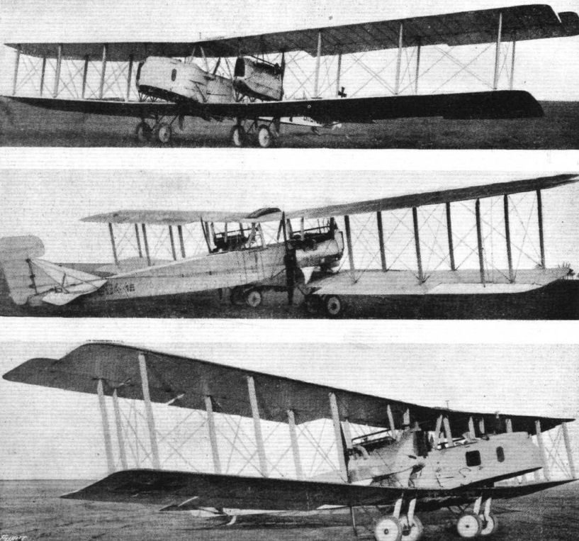
THREE VIEWS OF A GOTHA BOMBING BIPLANE. - It will be seen that it differs slightly from that described in "FLIGHT" for December 27th last, in that there is little or no sweep back, and that the engine housings are considerably modified.
The Gotha G V used the same engines as the Gotha G IV, following it into operational service in 1918. Top level speed of the G V was 87mph, while cruising speed was 80.8mph. Range of the G V was quoted as 522 miles, but this figure clearly reflects operations with a reduced bomb load. 120 G Vs are reported to have been built, plus 25 G Va and 55 G Vb, the latter two variants being equipped with biplane tail units.
The Gotha G V used the same engines as the Gotha G IV, following it into operational service in 1918. Top level speed of the G V was 87mph, while cruising speed was 80.8mph. Range of the G V was quoted as 522 miles, but this figure clearly reflects operations with a reduced bomb load. 120 G Vs are reported to have been built, plus 25 G Va and 55 G Vb, the latter two variants being equipped with biplane tail units.
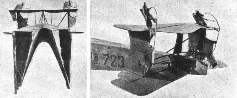
Figs. 38 and 39. - Two views of the biplane tail and fuselage of the twin-engine Gotha bomber. Illustrations and a brief description of this tail were published in our issue of October 3rd.
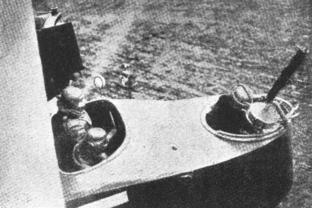
Fig. 41. - Twin-engine Gotha. Front of fuselage. Note Morell anemometer air-speed indicator.
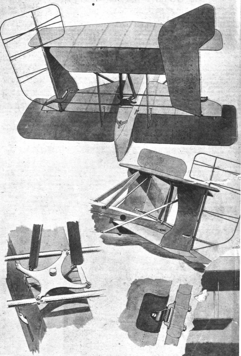
A Gotha biplane tail.
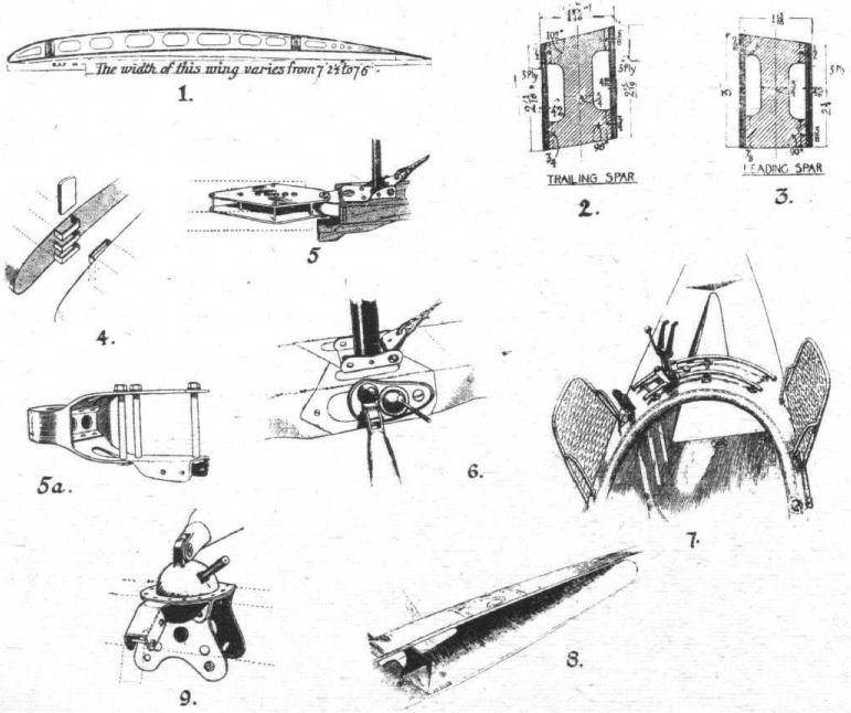
SOME CONSTRUCTIONAL DETAILS OF THE GOTHA BOMBER. - Figs. 1 to 9.

Some constructional details of the Gotha twin-engine bomber. Figs. 10 to 17.

Some more constructional details of the Gotha twin-engine botnber. Figs. 18 to 27.
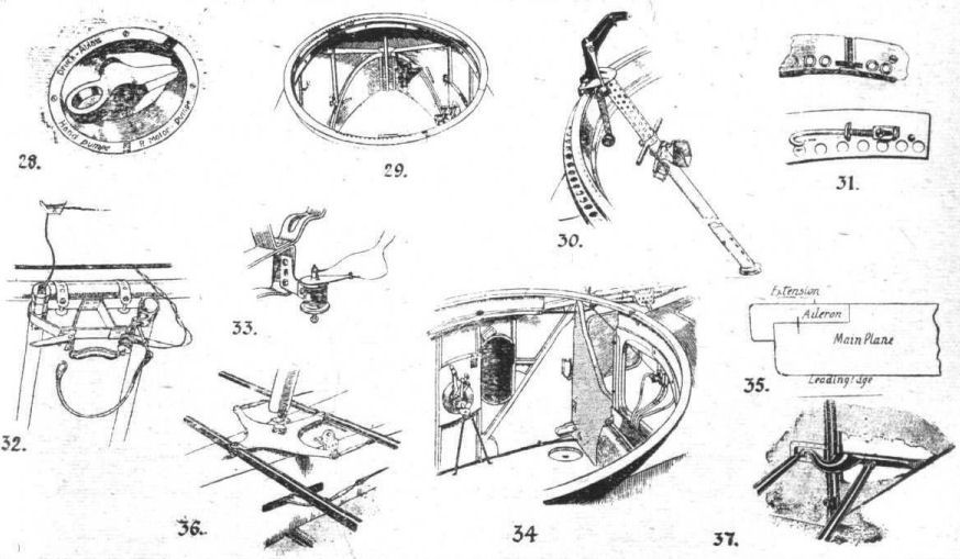
Constructional details of the Gotha twin-engine bomber. Figs. 28 to 37.
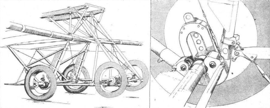
Three-quarter front view of one of the four-wheeled Gotha undercarriages. On the right a more detailed drawing of the shock-absorbing arrangement.
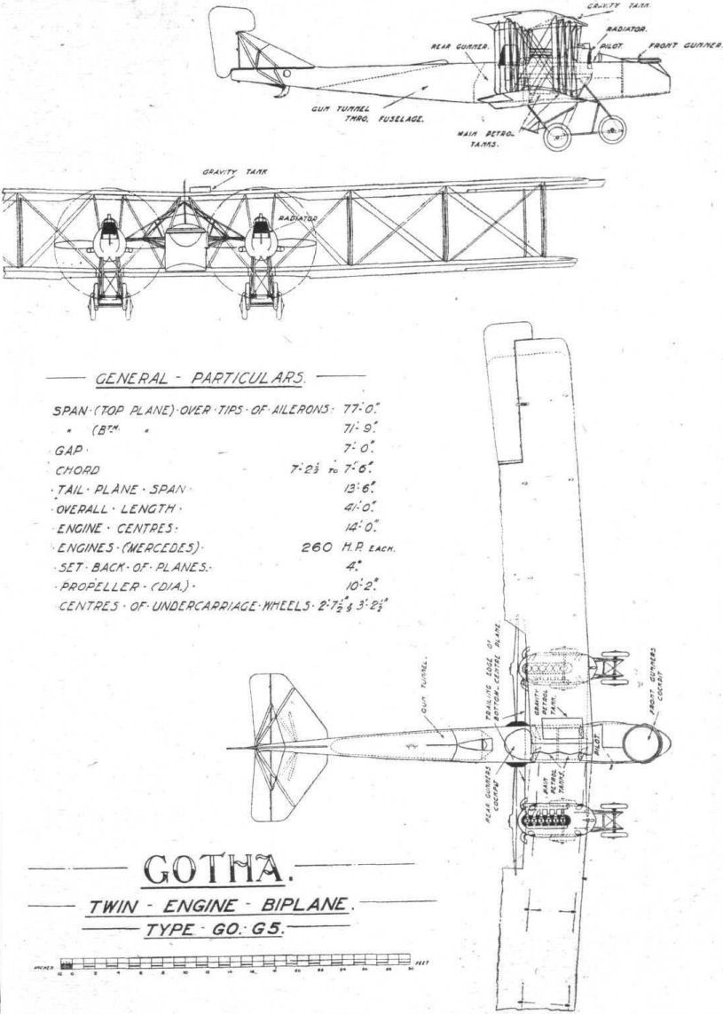
THE GOTHA BOMBER. - General arrangement drawings.
Flight, October 10, 1918.
REPORT ON THE HALBERSTADT FIGHTER.
(Issued by the Technical Department (Aircraft Production), Ministry of Munitions.)
[A brief description and a sketch of the fuselage of this machine were published in our issue of August 1st, 1918. - ED.]
THIS machine is a two-seater fighter. It was brought down at Villers Bocage, by Lieuts. Armstrong and Mert on an R.E.8 on June 9th, 1918. The machine is marked "Type H.S. C.L.2," and bears the military number C.L.2, 15,342/17. The date of construction, April 14th, 1918, is stamped on various parts. On the side of the fuselage is the following description :-
Leergewicht (weight unladen), 796 k.g.
Hochstbelastung (useful weight), 370 k.g.
Einschl Vollen tank. (Including full tanks.)
There is also a red line about 30 in. long drawn at both sides of the fuselage, showing the horizontal in the normal flying position.
General Details.
The Halberstadt represents, in all probability, the high water mark of two-seater German aeroplane construction, as it is not only well and strongly constructed, but its general behaviour in the air is good according to modern fighting standards.
Its general design will be gathered from the drawings on page 1135 and also from the photographs. Constructional details are dealt with by sketches.
Span of upper plane, 35 ft. 3 1/4 in.; span of lower plane, 34 ft. 11 in.; chord or upper plane, 5 ft. 3 1/4 in.; chord of lower plane, 4 ft. 3 1/2 in.; gap, maximum, 4 ft.; gap, minimum, 3 ft. 8 1/2 in.; dihedral angle of lower plane, 2 deg.; horizontal dihedral of main planes, 4 deg.; total area of main planes, 310 sq. ft.; area of each aileron, 11.6 sq. ft.; area of aileron balance, 2 sq. ft.; load per square foot, 8.2 lbs.; area of tail planes, 13.6 sq. ft.; area of elevator, 12.4 sq. ft.; area of fin, 6.4 sq. ft.; area of rudder, 7.9 sq. ft.; area of rudder balance, 1 sq. ft.; maximum cross-section of body, 8.8 sq. ft.; horizontal area of body, 44 sq. ft.; vertical area of body, 52.8 sq. ft.; length over all, 24 ft.; engine, 180 h.p. Mercedes; weight per h.p. (180), 14.07 lbs.; capacity of petrol tanks, 34 galls.; capacity of oil tanks, 4 galls.; crew, 2; guns, 1 fixed and 1 movable; military load on test, 545 lbs.; total load on test, 2,532 lbs.
Performance.
Speed at 10,000 ft., 97 m.p.h., 1,385 r.p.m.
Rate of
climb in Indicated
Mins. secs. Ft./min. Air speed
Climb to 5,000 ft. 9 25 440 69
Climb to 10,000 ft. 24 30 240 64
Climb to 14,000 ft. 51 55 80 58
Service ceiling (height at which climb is 100 ft. per minute), 13,500 ft.; estimated absolute ceiling, 16,000 ft.; greatest height reached, 14,800 ft. in 64 min. 40 sec.; rate of climb at this height, 50 ft. per minute.
Stability and Controllability.
This machine cannot be considered stable. There is a tendency to stall with the engine on, and to dive with the engine off. Directionally, owing to the propeller swirl, the machine swings to the left, but with the engine off is neutral.
Pilots report the machine light and comfortable to fly. The manoeuvrability is good, and this feature, taken in conjunction with the exceptionally fine view of the pilot and observer and the field of fire of the latter, makes the machine one to be reckoned with as a "two-seater fighter," although the climb and speed performances are poor judged by contemporary British standards.
Principal Points of the Design.
Single bay arrangements of wings.
Conspicuous set back of the main planes.
Empennage free from wires.
Fuselage tapers to a horizontal line at the rear in direct contradistinction to the usual German practice.
Pilot's and observer's cockpit constructed as one.
Construction.
Wings.
The upper wings are supported by a large centre section, having a span of 6 ft. 3 in. This centre section is at right angles to the centre line of machine, but at each side of it; the wings are thrown back with a horizontal dihedral of 4 deg. The lower wings are smaller in chord and very slightly smaller in span than the upper, and are fixed direct to the lower surface of the fuselage, and it is to be noted that where the trailing edge joins on to the fuselage it is shaped so as to avoid a surface of discontinuity at the root of the wing. This is done by smoothly turning upwards the trailing edge.
The actual construction of the wings is of considerable interest, especially on account of the novel type of spar which is employed. This applies to both the upper and the lower planes. The front spar measures 2 3/4 in. by 1 in. and at the butt is placed about 4 in. from the leading edge. It is of "I" section, but is left full at such points as those at which internal bracing wires are fixed. A section of this spar, given in Fig. 1, shows how it is connected to the leading edge by means of ply-wood, both top and bottom.
It will be seen that on the upper surface the ply-wood is extended rearwards for a distance of some 4 3/4 in. from the centre of the spar, and terminates in a small transverse flange about 1/2 in. deep. This construction furnishes a leading edge of great rigidity and strength, and at the same time it would also appear to be light in weight.
A section of the rear main spar is given in Fig. 2. In this case the main member is of "O" or box section, and is built up of two pieces let into one another in a rather unusual manner. This is clearly shown in the drawing. Both at the top and bottom of the spar, thin strips of wood are used to cover the glued joint, and on this is tacked, both above and below, a flat length of ply-wood 7 in. wide which overhangs the main member of the spar an equal distance at each side.
This ply-wood web is flanged at each end with strips of wood glued in position, and on these strips are fitted small corner pieces which serve to support the ribs. The latter are also of ply-wood, to which are glued and tacked rails of solid wood, top and bottom.
A notable point of the wing construction is the fact that steel tubes are not used as the compression members of the internal bracing, as is the common practice. These members are made of box form ribs which occur at intervals along the spars. Adjacent to the root of the wing a very large reinforced box rib occurs, of which the section is given in Fig. 3.
The absence of steel tubes considerably simplifies the attachment of the bracing lugs to the spars, a specimen of which is shown in Fig. 4. It will be noticed that it is of a very simple form, and in this respect it is characteristic of the design of the aeroplane on the whole, which, from this point of view, is far less elaborate than the majority of German designs and appears to be in many ways more practical, especially having regard to quantity production.
Wing Attachments.
The whole of the centre section, both upper and lower surface, is covered with three-plywood, and the spars used in it are of similar design to those fitted to the wings, and already described. Both the upper and lower wings are provided with attachments which allow of their being very readily taken down. Views -of these fittings are given in Figs. 5 and 6, the former showing the attachment of the upper wing to the centre section, and the latter that of the lower wing to the fuselage. In the former case, the fitting is covered in with a spring operated trap door which also gives access to the joint of the aileron' control shaft. A sliding door is used in the lower plane, and it will be noticed that the spar is at this point protected by an aluminium foot plate. In each case, quick detachable safety bolts are employed. In Fig. 7 are given further details of the type of spar socket in use. This is built up of sheet steel and oxy-acetylene welded, the quality of this work appearing to be very high.
The spars of the lower wings engage with a fork-ended tube passing right across the floor of the fuselage, and supported by the longerons of the nacelle by means of the sockets as shown in detail in Fig. 8. Here, again, a high quality of workmanship is evident, and it may be said without exaggeration that in this respect the Halberstadt machine is decidedly superior to the other German aeroplanes which have been reported upon, with, perhaps, the single exception of the Fokker.
Struts.
The struts throughout this aeroplane are of streamline steel tube of light section, but in contradistinction to the usual German practice they are not tapered at the ends, but end abruptly, as shown in Fig. 9. This form of construction has the advantage of lending itself very well to the saving of labour, as the aeroplane struts are simply lengths of plain tubing pierced with transverse holes and reinforced by welded shoulders where the latter occur. The struts are secured top and bottom by bolts and eyes, and it will be noticed that where a cross bracing wire has to be taken from this junction, the turnbuckle is neatly anchored to a small pin passing through the rear of the tubular strut, which is slotted and slightly expanded at this point.
The bolt hole is also reinforced by spot welding. This arrangement of strut attachment appears to be very practicable and certainly looks extremely neat.
The upper ends of the inclined centre section struts are fitted with a different type of anchorage, as in this position the simple form of attachment used on the interplane struts cannot be adopted. A sketch is given in Fig. 10, from which it will be seen that the end of the strut is welded up solid and fitted with a scooped-out slot for the reception of the diagonal wire which runs to the bottom of the fuselage. This wire is very neatly secured by the same bolt as fixes the centre section strut.
The rear spar of the centre section is supported by two vertical struts of the "V" type having their base points attached to the upper members of the fuselage and the apex fixed to the centre section spar. The manner in which the lower joints are fitted to the fuselage brackets and the form of the latter are made clear in Fig. 11.
The bracing wires run as follows :- In the rear between the extremities of the struts; the lift wire in front joins the top of the forward strut to the landing carriage strut. There are no drift wires outside the wings.
Fuselage Construction.
One of the most notable points in the Halberstadt fuselage is that whilst it retains the characteristic German form, both forward and amidships, it shows great individuality at the tail, at which point it tapers to a horizontal line, instead of to a vertical line, as is the practice in nearly all other German aeroplanes. The advantage of this arrangement is that the fitting of the tail can be made of sufficient strength without introducing any need for wire bracing. Thus, apart from head resistance, it has less masking effect on the movable gun.
The fuselage is constructed in the accepted manner of four main longerons fitted with skeleton bulk heads at intervals and covered in with three-ply wood. The bulk heads are made as shown in Fig. 12, and are of a very light construction, except that adjacent to the tail, which serves as the main support of the rudder post and tail plane spar. At this point the bulk head is made of multi-ply wood, and is extensively fretted, as shown in the sketch, Fig. 13. Slots are cut for the reception of the longerons. The rudder post is fixed to the bulkhead by sheet steel brackets.
The sketch, Fig. 14, shows in more detail the fitting of the longerons to this bulk head, and it will be noticed that wedge-shaped filling pieces are used, and also that the longeron itself is wrapped with fabric throughout its length. Immediately in front of this tail bulkhead, and at each side of the fuselage, a small vertical wooden member is dropped from the upper longeron. This, together with the bulkhead, serves to support the bracket which carries the leading edge of the fixed tail planes. This will be referred to later.
Another notable feature of the fuselage is the fact that the pilot's and gunner's cockpits are made in one without apparently introducing any weakness into the construction. This scheme has the advantage of permitting the pilot and passenger to sit very close together, so that the length of the fuselage is reduced. The two cockpits, whilst to all intents and purposes in one, are actually separated by a cross-piece, which is used as a tray for the convenience of the observer. It is, however, probable that the primary object of this crosspiece is to perform a constructional function.
The gun ring does not, as in the usual design, form an integral part of the fuselage coaming, but is fitted thereto by brackets.
Inside the observer's cockpit, the fuselage is reinforced, between the floor and the sides, by slightly curved panels, as shown in the sectional sketch, Fig. 15. In the space formed by these panels run the control wires, which are thus out of the way and cannot accidentally be interfered with by the observer.
Empennage.
As is shown in the general arrangement drawings, the empennage consists of curvilinear fin with balanced rudder, and a semicircular tail plane to which is hinged a single elevator. As has alreidy been noticed in the description of the fuselage construction, the mounting of these tail planes is carried out without the use of any external wiring or cross-bracing. The fixed tail planes are built up of steel tubes, and have a section curved both top and bottom. The rear spar, which acts as part of the hinge of the elevator, is carried in a pair of built-up welded steel brackets, which form the end piece of the fuselage, as shown in Fig. 16. The front spar, which is slightly in the rear of the leading edge, is capable of being adjusted when the machine is on the ground, so as to vary the angle of incidence of the tail planes. The adjustable clip for this purpose is shown in Fig. 17, and gives a choice of four positions. The built-up steel brackets, which form this attachment, are carried, one on the rearmost bulkhead, shown in Fig. 13, and the other on the small vertical strut, noted in Fig. 14.
The method of construction of the fin and rudder is shown in Figs. 18 and 19. The same principle is adopted for the tail planes and elevator. It will be seen that it is a combination of wood and steel construction. The ribs of the fin, which is curved in section, and has a rounded leading edge, consist of thin steel tubes, 8 mms. in diameter, welded to the leading spar, and taken back to the rudder post at a slight angle to each other. This staggering of the tubes gives the rib the thickness of a single tube only at the trailing edge. They are reinforced with diagonal tubes of 5 mms. in diameter. The leading edge is formed by a covering of thin three-ply wood supported by a light wooden framework, the form of which is indicated in Fig. 19.
Ailerons.
The ailerons are of the balanced type, and are fitted on the upper plane only. They are furnished with the usual welded steel framework, and are very light in weight. Their method of operation differs from that found on any other German design. The aileron front spar, which is hinged to the rear spar of the wings, is continued inwards by means of a tubular steel extension until it reaches a point level with the side of the fuselage. Here the extension of the shaft terminates in a crank, which is operated direct by the "T" shaped control lever through the medium of vertical steel rods.
The arrangement of these ailerons and their levers may be gathered from the photographs, Nos. A and B. Fig. 5 shows how the aileron operating shafts are split and provided with bolted flanges whereby that end of the shaft which is carried in the centre section of the upper plane may be easily detached from the portion which is housed in the wing. Figs. 20 and 21 illustrate details of the attachments of the aileron shaft to the aileron itself. The bearings of the shaft consist of a flanged plate at each end, as shown in the drawing, Fig. 20. On the inner side is a coupling which unites the front spar of the aileron to the operating shaft. Each of these members terminates in a semicircular driving dog, and the two are united by a clamped sleeve which is also fitted with a locating cotter pin. This allows the aileron, as a whole, to be removed very readily in case of need. The tips of the ailerons are turned up at their extremities so as to present, when the controls of the machine are in their normal position, a slightly negative angle to the relative wind. This is in conformity with the usual German practice.
Control.
A sketch of the control gear is given in Fig. 22. It is, in general, of the usual type, and the lever is fitted with a locking device, whereby the incidence of the elevator can be fixed when desired. This consists of a light telescopic tube arranged diagonally and fitted with a clamp, operated by a thumb screw. The control lever is fitted with an "L" shaped extension at its base, which is pivoted to a long crank bar. This is fitted with bell cranks at each end, and is carried in bearings mounted in the sides of the fuselage in such a manner that the bottom end of the lever is coincident with the centre line of the pivot bearings. As shown in the sketch, the control lever has a "T" piece attached to its foot, which is coupled up through universal links to rods, which extend vertically to the aileron cranks. The ailerons are thus worked entirely positively, and without any cables and pulleys.
Mounted at the head of the control levers are two triggers for operating the fixed machine guns for which accommodation is provided, though only one was actually found on the aeroplane.
The rudder is controlled by a built-up foot bar with the usual heel rests. This is carried in a pivot mounted on a light steel tube fixed across the fuselage longerons. Below this tube the rudder bar pivot carries a grooved pulley of large diameter, over which the rudder wire is passed. It is then taken over pulleys at each side, and down the fuselage to the cranks at the rudder post.
It is worthy of note that whilst none of these controls are duplicated, the elevator cranks are fitted with two sets of bolt holes, so that the leverage can be adjusted if necessary.
Undercarriage.
The undercarriage consists of a steel axle, fitted with 760 by 100 wheels. The axle is supported from a pair of tubular steel struts at either side by means of triple steel coil spring shock absorbers. The upper attachment of the undercarriage struts is shown in Fig. 23, which illustrates the form of bracket carried on the outside of the fuselage, and bolted to one of the forward bulkheads. The struts are reinforced for the reception of the bolts in a manner similar to that described for the interplane struts.
At their bottom end, the struts are welded together into the form shown in Fig. 24, and they are also reinforced by a fixed axle or tie-rod, the sockets of which are slotted for the reception of the turn-buckles of the cross-bracing wires.
The undercarriage design is considerably neater than that found on the general run of German aeroplanes, and appears to be both strong and light.
Tail Skid.
A view of the tail skid is given in Fig. 25, and it will be seen that this possesses one or two features of interest.
The skid itself is of ash, reinforced with a light built-up sheet steel shoe. The forward end projects through a hole in the fuselage, and is fitted with the usual shock-absorber device, which is fastened to the rearmost bulkhead.
The tail skid is pivoted to an extension of the rudder post, and though it is capable of swinging slightly from side to side, is not actually steerable. Immediately above the shoe of the tail skid, is a second steel shoe, shaped like a spoon, which is rigidly supported by a pyramid of steel tubes. The object of this is to prevent any possibility of the elevator cranks coming into contact with the ground, even should the tail strike the earth sufficiently hard to carry the tail skid shock absorber to its limit of extension.
Engine.
The engine is a high-compression 160 h.p. Mercedes (commonly known as 180 h.p.), and is of standard type. This engine has been fully described in Handbook No. 805.
Engine Mounting.
The engine bearers are of wood, and are directly supported by bulkheads in the forward part of the fuselage.
Petrol Tanks.
There are two tanks for petrol. The main supply is carried under the pilot's seat, and has a capacity of 24 galls. This is fed to the carburettors under air pressure, and the usual hand and engine pumps are employed.
The second tank is let into the upper surface of the centre section of the top plane, and is clearly shown in Photo. B. This contains 8 galls., and is fitted with a glass tube, lying parallel to the upper curvature of the plane, by which the pilot can readily see the level of the fuel. This gravity tank can be filled from the main tank by means of a semi-rotary hand pump.
Radiator.
The radiator is of the type which is becoming more and more adopted by German designers, namely, that which is embodied in the upper plane surface. In this case the radiator forms part of the right-hand side of the centre section. It is fitted with a small subsidiary water tank, details of which are shown in Fig. 27, which is provided with a trumpet nozzle pointing forward. Details of the radiator shutter are given in the photograph No. A. Provision is made for the fitting of a water-circulation thermometer, but this instrument was not actually found on the machine. The radiator shutter consists of a sliding panel of sheet steel mounted on a light tubular framework forming rails. This is within easy reach of the pilot, and can easily be slid forward or backward when it retains its position by reason of the lift effect upon it, and the friction between the guides and the rails.
As shown in sketch, Fig. 26, the inlet and outlet pipes of the radiator are both fitted at its left-hand front corner, the radiator being furnished with internal baffles, which promote complete circulation of water through all the tubes. In order to prevent the possibility of an air-lock forming, a small tube is led from the outlet pipe through the bottom of the radiator tank, and is brought close to the bottom side of its top surface. If air should accumulate in the forward and upper part of the radiator, this tube would quickly allow the lock to be dissipated.
The sketch, Fig. 26, shows the adapter for the radiator thermometer in the outlet pipe. From the inlet pipe, a small branch is taken off for the carburetor jacket, and from the rear end of the radiator, a pipe provided with a cock, by which the tank can be emptied, is led to the trailing edge of the upper plane.
Oil.
A supply of 5 galls, of oil is carried in a small tank fitted at the side of the engine. The latter is furnished with a pump, which, while circulating the lubricating oil contained in the tank, draws a small supply of fresh oil from the tank at every stroke.
Propeller.
The screw is of the usual built-up type, and consists of eight laminations of woods in the following order :-
Ash, ash, mahogany, ash, mahogany, ash, mahogany, ash.
It has a diameter of 2.4 metres and a pitch of 2 metres, and was built at the Luckenwalde Propellerwerke, Niendorf. In front of the propeller boss proper is a built-up laminated plate to which a spinner is fixed by means of a girdle of stranded steel cable.
Wireless.
The aeroplane is internally wired to give greater capacity for wireless, and accommodation is provided for the aerial and its spool in the observer's cockpit. The wireless dynamo, which also provides current for electrically heating clothing, is driven direct from a pulley on the engine, and is mounted on a bracket carried by the left-hand engine bearers.
The form of this bracket is shown in Fig. 28, which also indicates the manner in which it is adjustable. The bracket consists of a flanged and welded sheet steel construction comprising two plates. The upper extremities of these plates are joined by a transverse bolt on which is hinged a pad against which the foot of the dynamo base is bolted. A similar bolt and pad is furnished at the bottom of the plates, but in this case the bolt is adapted to slide in a guide so that the tension of the belt can be adjusted and the bolt and its pad locked in any position by a thumb screw.
The dynamo, when fitted, lies outside the wall of the fuselage at a point level with the rear of the engine, and is then covered in with a bulbous streamline fairing. When the dynamo is not (the whole of the wireless apparatus being installed only when actually required) fitted, this streamline fairing, which is readily detachable, has its place taken by a flat panel which can be discerned at the left-hand side of the fuselage in photograph No. B.
Engine Control.
A throttle lever of the usual ratchet type is fitted at the left-hand side of the pilot's cockpit, the carburettor being fitted with an automatic altitude connection. On the dashboard is a screw-down grease pump, for lubricating the water-pump spindle.
Ignition is controlled by a self-locking lever. The dashboard is completed with the usual instruments-starting magneto, main switch, petrol pressure gauges, oil-pressure gauges, air pump, and petrol lever indicator. On the right-hand side of the pilot's seat is a lever controlling the clutch of the wireless dynamo drive.
Level Indicator.
A level indicator of the type shown in Fig. 29 is fitted on the dash board. It is of a type not previously found on German aeroplanes. It consists of a pendulum device, operating a circular disc, the lower half of which is covered by a semicircular metal shield. The upper half of the disc is dark in colour, though not quite so dark as the shield, and below its horizontal diameter the swinging disc is painted white, so that if the machine side-slips a white sector becomes visible against a dark background, as indicated in the sketch. This instrument appears to be very much better made than the usual indicators fitted to German machines.
Gun Mounting.
A notable feature of the Halberstadt machine is the fitting of the gun ring, which is not incorporated in the fuselage, but is attached to its top surface by streamline steel struts. In front, it is supported by two converging steel tubes in a form of a "V" which branch from the upper fuselage longerons. The gun ring is thus very rigidly supported. Since the greater part of it is directly in the slip stream of the screw, it is made of very fair streamline section, as may be gathered from the photograph No. A, and in general is much lighter and far better constructed than the usual German gun mounting. The accepted type of bracket and locking device is employed. Both portions of the ring are made of wood covered with doped fabric.
Fabric.
The fabric is of the usual quality found on the better class of German aeroplanes. It is dyed with the familiar polygonal camouflaged scheme of colours, and is applied to the wings with the warp and weft at an angle of 45 deg. to the spars. The reason for this method of wing covering is not clear. The dope used appears to be good. The body work and also the centre section of the top plane are covered with a scumble of colours arranged in indefinite areas and shading into one another. The colours used are a cloudy yellow, dark and light greens, brown, purple and a light blue. The belly of the fuselage is coloured yellow throughout.
Fittings.
In the floor of the observer's cockpit, is a bracket for a camera of one metre or more focal length. Detachable tubes for supporting the upper end of the camera are furnished, and for this purpose clips are fitted on the fuselage members. A sliding trap door underneath the camera fitting is provided. Plugs at convenient points are arranged for the electrical heating circuit. The observer's seat is of the folding type, and is placed very low, so that when he occupies it, the observer is well below the level of the top of the fuselage, and is thus completely hidden from view. The pilot's seat is adjustable fore and aft, and is carried on light built-up cross bars dropped into sockets bolted to the fuselage members. The form of the sockets is shown in Fig. 31.
Compass.
The compass, which is of the usual German pattern, presenting no new features, is fitted in a circular box near the root of the left-hand wing, where it is immediately under the view of the pilot.
Schedule of Principal Weights. lbs. ozs.
Total weight 2,532 0
Upper wing, complete with aileron, aileron rod,
drag bracing, and strut attachments, but
without lift bracing wires and fabric 62 6
Lower wing, as above (no aileron fitted) 52 8
Aileron complete, without fabric 7 12
Aileron bar, with flange 4 0
Interplane strut, front, without bolts 3 3
rear 3 14
Centre section, complete, with radiator and
gravity tank, aileron control crank, and
bracing wires 101 0
Fixed tail plane (each), with fabric 7 8
Rudder, complete, with fabric 7 8
Elevator, complete, with hinge clips and fabric
12 0
Fin, complete, with fabric 9 6
V centre section strut 2 7
Straight centre section strut 3 2 1/2
Undercarriage, complete, with struts and bracing,
wheels, tyres, and shock absorbers 102 0
Shock absorber (multiple coil spring type), each
4 6
Axle, with shock absorber bobbins and caps
14 8
Wheel, with tyre 20 4
Tyre and tube 8 12
Wings, leading spar, per foot run 1 4
Wings, trailing spar, per foot run 0 14 1/2
Historical Note.
The present Halberstadt fighter is a development of the earlier single-seater, an example of which was brought down on October 29th, 1917. [A similar machine was described and illustrated in "FLIGHT" for April 5th, 1917, and August 23rd, 1917 - ED.] In the latter case ash was used to a fairly large extent, both in the fuselage and wings, but in the more modern design spruce is exclusively adopted. The rear spar was of the ordinary I-Section type without three-ply reinforcement. The fuselage, of somewhat similar shape, was fabric covered. Balanced elevators and rudder were fitted, but no fixed tailplane or fin. The arrangement of the centre section, with tank and radiator, was substantially the same. Double bays of interplane struts were adopted, but the struts themselves were of the welded-up tapered pattern. The ailerons were controlled by wires, and not, as in the present example, positively. Both planes had the same chord, and the upper wings had an overhang. The weight of the complete machine, without pilot, was 1,778 lbs.
Both the Halberstadt machines are at the Enemy Aircraft View Room, Agricultural Hall, Islington, where they may be seen on production of a pass, obtainable from the Controller, Technical Department. Ap. D. (L.), Pen Corner House, Kingsway, W.C.2.
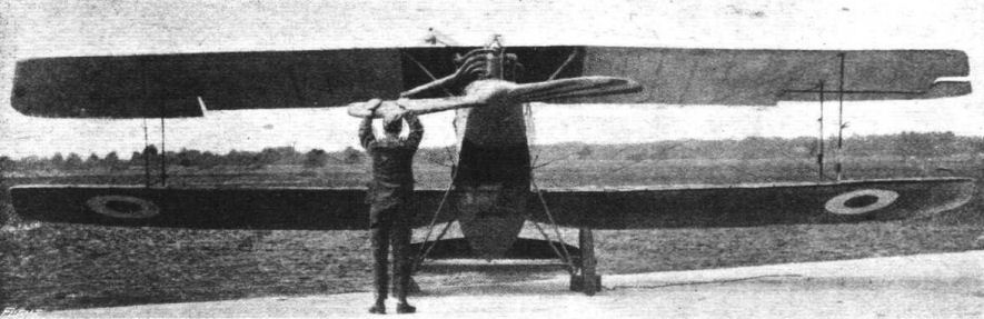
Front view of the Halberstadt fighter.
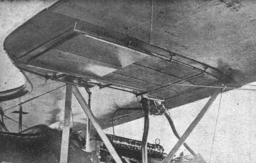
A. View of underside of centre section, showing radiator and shutter, machine gun and cabane struts.
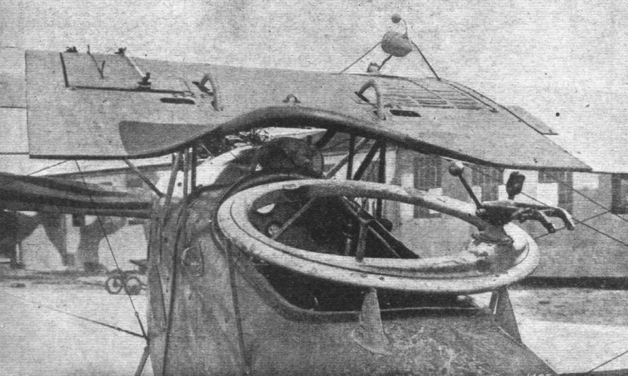
B. View of cockpits, showing aileron cranks, gun ring, radiator and gravity petrol tank.
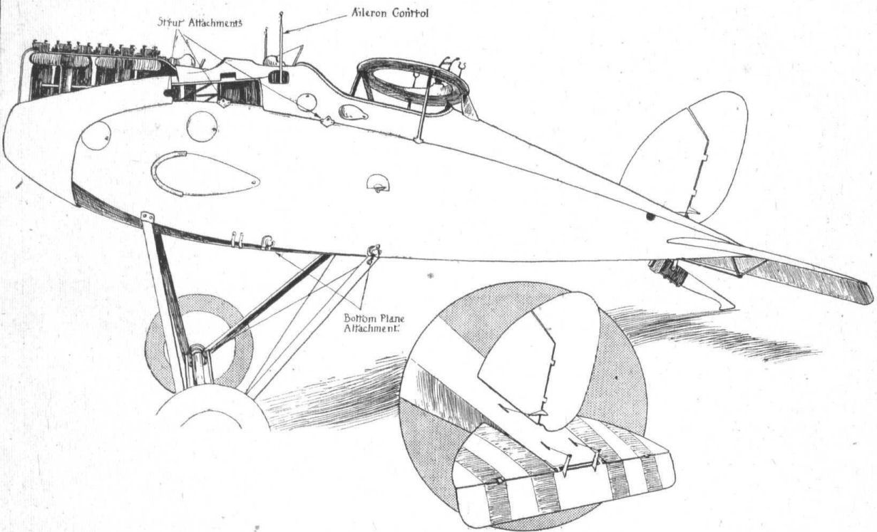
Perspective drawing of the body of the Halberstadt two-seater biplane, 160 h.p. Mercedes engine. Inset is a sketch of the tail planes.
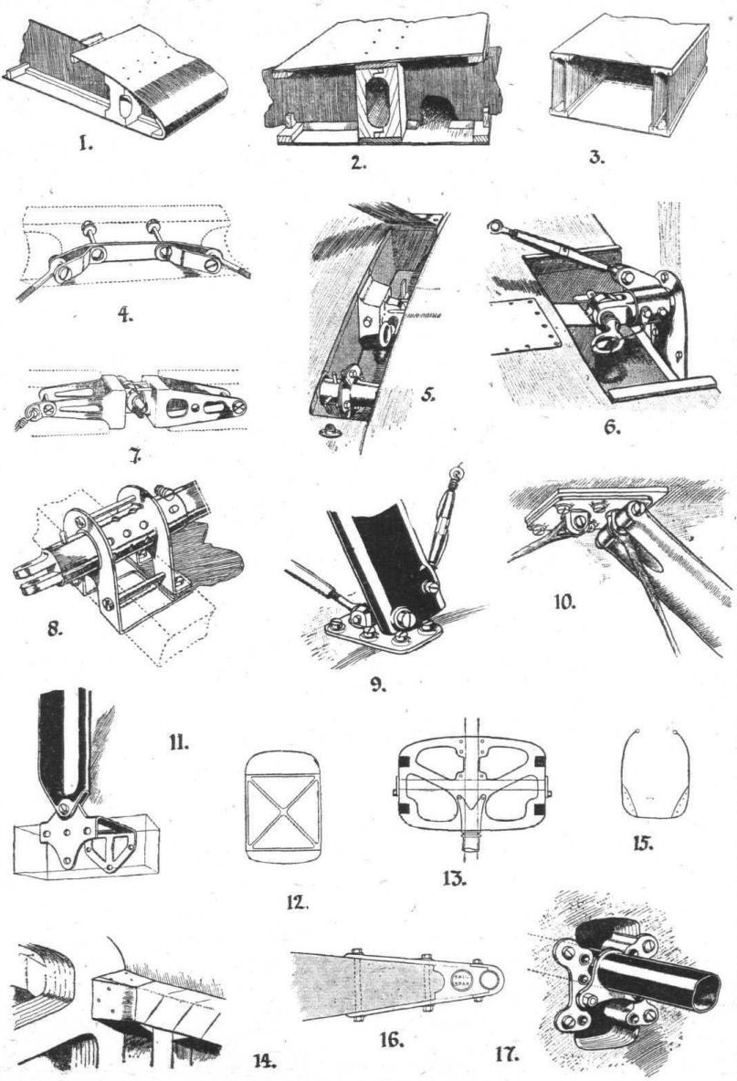
Some constructional details of the Halberstadt fighter. (Figs. 1. to 17.)
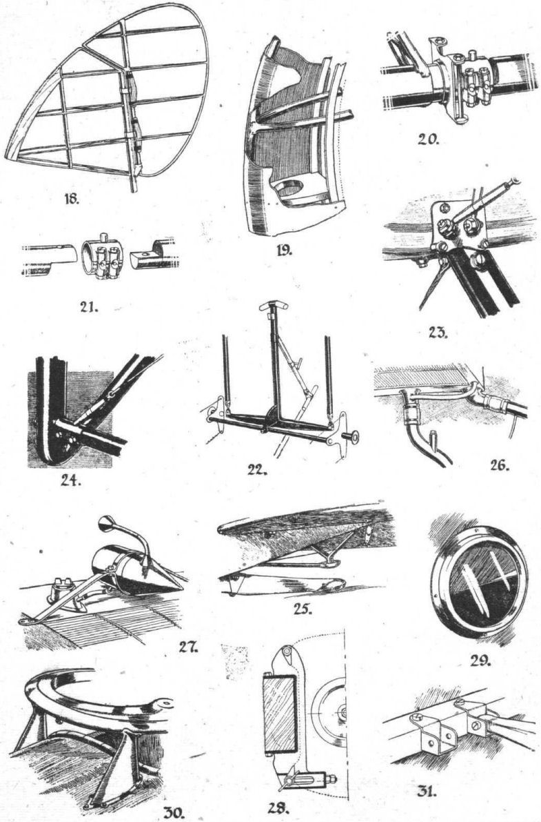
More constructional details of the Halberstadt fighter. (Figs. 18 to 31.)
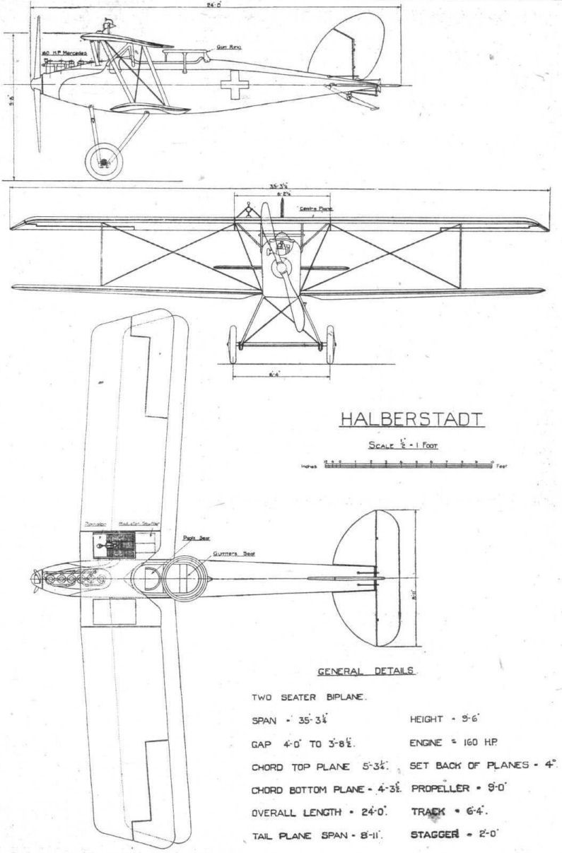
Flight, December 12, 1918.
THE HALBERSTADT TWO-SEATER TYPE C.L. IV
[Issued By Technical Department (Aircraft Production), Ministry of Munitions]
THIS machine, which is allotted G/5Bdr./22, landed near Chipilly on August 23rd, 1918. Dates stamped on the main planes give the date of construction as July, 1918.
It is very similar in design and construction to the C.L. II type, which has already been fully reported upon (see issue of "FLIGHT" for October 10th), but many detail differences are incorporated.
Below is a comparative list of the principal dimensions of both C.L. II and C.L. IV types :-
C.L. IV C.L. II
Span of upper plane 35 ft. 2 1/4 in. 35 ft. 3 1/4 in.
Span of lower plane 34 ft. 9 1/4 in. 34 ft. 11 in.
Chord of upper plane 5 ft. 2 5/8 in. 5 ft. 3 1/4 in.
Chord of lower plane 4 ft. 3 1/2 in. 4 ft. 3 1/2 in.
Gap, maximum 4 ft. 4 in. 4 ft. 0 in.
Gap, minimum 4 ft. 0 in. 3 ft. 8 1/2 in.
Dihedral angle of lower plane 2 deg. 2 deg.
Horizontal dihedral of main planes 4 deg. 4 deg.
Total area of main planes 308 sq. ft. 310 sq. ft.
Area of each aileron 12 sq. ft. 12 sq. ft.
Area of aileron balance 2.0 sq. ft. 2.0 sq. ft.
Area of tail planes 16 sq. ft. 13.6 sq. ft.
Area of elevator 13.6 sq. ft. 12.4 sq. ft.
Area of fin 11.4 sq. ft. 6.4 sq. ft.
Area of rudder 7.9 sq. ft. 7.9 sq. ft.
Area of rudder balance 1.0 sq. ft. 1.0 sq. ft.
Horizontal area of body 36 sq. ft. 44 sq. ft.
Vertical area of body 41 sq. ft. 52.8 sq. ft.
Length overall 20 ft. 11 1/2 in. 24 sq. ft. 0 in.
Engine 180 Merc. 180 Merc.
Capacity of petrol tanks 34 galls. 34 galls.
Capacity of oil system 4 galls. 4 galls.
Crew Two Two
Guns One fixed and one movable
Wings
The wings, both in disposition and construction, are substantially the same as in the former machine. The characteristic wash-out at the root of the lower planes is even more pronounced than was the case in the C.L. II machine. It will be seen from photograph A that the rear spar is bent and twisted by this wash-out. The exact shape of the trailing edge of one of the lower planes is shown in the scale drawings.
Fig. 1 gives a section of the upper wing drawn to scale, and Fig. 2 a comparison of the upper aerofoil of the C.L. IV with the R.A.F. 14 section, which is dotted. From Fig. 1 it will be noticed that the 3-ply surrounds to the spars are still employed. They are drawn to scale in Fig. 3.
The ailerons remain unaltered in the C.L. IV machine, and this is also true of the interplane and centre section struts.
The attachment of upper wings to centre section and of lower wings to fuselage are unaltered, except that the tube which, in the earlier machine, passed right across the fuselage and connected the spars of the port and starboard lower wings is no longer found. Its place is taken by two fuselage fittings of the type shown in Fig. 4.
Fuselage
Although the fuselage of the C.L. IV machine is very like that of the C.L. II type, the machine now being described has a body which is practically 3 feet shorter than that of the earlier machine.
Tail planes and Skid
It is in these components that the greatest differences between the two types are found. The tail plane is now in one piece, and is laid across the rear of the fuselage, and attached there by the bolts shown in Fig. 6. The undivided elevator is now balanced, and the aspect ratio of the whole horizontal tail is larger than was the case in the earlier model. Besides this the actual area is greater. (It has been remarked that the C.L. IV body is 3 feet shorter.)
The fin and rudder were not salved, and comparison is therefore not possible, but it is clear from the fuselage design that the fin is a separate unit simply attached to the body, and not an integral part of it. It is also established that the rudder post is now found in the same vertical plane as the leading edge of the elevator. It will be remembered that the rudder post, in the C.L. II type, was fixed more than a foot forward of the elevator fulcrum.
The inverted camber of the C.L. II tail plane is now abolished, and a symmetrical camber substituted, and the rather elaborate tail skid of the earlier model has been simplified to the type found in the modern L.V.G. biplanes. In this type the skid is entirely exposed, and is pivoted on the lower edge of a small triangular fin under the tail plane. (See photograph and general arrangement drawings.)
Undercarriage
The landing gear is substantially the same as in the C.L. II machine, but, as may be seen in Fig. 5, two compression tubes now run parallel to the axle, instead of one, as before.
Fittings
The gun ring has been additionally stayed in front, but otherwise remains the same. It was fitted with a Parabellum gun.
Two fixed guns of the Spandau type are arranged for, one each side of the camshaft, but only the one on the starboard side was fitted at the time of capture.
A ten-loop Very cartridge belt is tacked to the top of the fuselage just behind the cockpit - it may be seen in the photograph - and a total of twelve light hand grenades may be carried in the wooden racks, one of which may be seen on either side of the fuselage.
The practice of enclosing the control wires in the cockpit is still continued, but aluminium shields are used instead of the more permanent three-ply construction.
The machine is internally wired, but no wireless apparatus was on board at the time of capture. The dynamo bracket is no longer to be found alongside the engine, but is now on the front port undercarriage strut, and is driven by a propeller.
The pilot's seat is a shallow three-ply bucket, which rests on two cross pieces of wood supported on ribbed brass strips sweated to the top of the petrol tank, thus providing a fair amount of adjustment. This is the subject of a sketch (Fig. 7).
The fabric is throughout of the usual colour-printed type.
Schedule of Weights, Halberstadt, C.L. IV.
lbs. ozs.
Body, with undercarriage, engine,
Spandau gun, petrol tank, gauges, and
controls 1220 0
Engine (dry), 180 Mercedes 635 0
Upper wing, complete (no bracing wires) 70 8
Lower wing, complete (with bracing wires) 64 0
Centre section, complete (with struts and
wiring) 108 8
Gravity petrol tank 11 4
Radiator 36 0
Centre section strut (Vee) 5 3
Centre section strut (straight) 2 4
Interplane strut (front), with cable 4 8
Interplane strut (rear), with cable 4 0
Undercarriage, complete, approximately 112 0
Shock absorber (one) 4 6
Axle, with bobbins and caps 14 8
Wheel, complete with tyre 20 4
Tyre and tube 8 12
Leading spar of wings (per foot run) 1 4
Trailing spar of wings (per foot run) 0 14 1/2
Tail plane and elevator (covered) 25 0
The aeroplane is in the Enemy Aircraft View Rooms, Islington, and may be seen on production of a pass, to be obtained by writing to :- The Controller, Technical Department, Ap.D. (L.), Central House, Kingsway, W.C. 2 .

Rear view of tail and fuselage of Halberstadt C.L. IV.
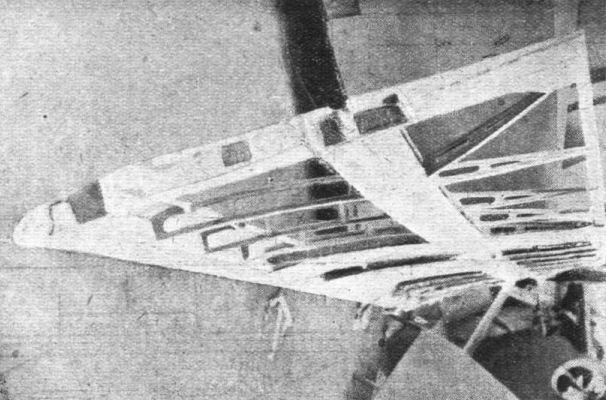
Photograph showing internal construction of lower plane of Halberstadt C.L. IV. Notice the pronounced wash-out.
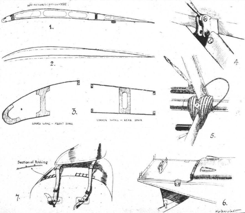
Some constructional details of the Halberstadt C.L. IV. - 1. Top plane wing section. 2. Comparison between the section shown in 1 and the R.A.F. 14. 3. The three-ply surrounds to the spars, drawn to scale. 4. Fuselage fitting for bottom plane. 5. Shock absorber and undercarriage cross-tubes. 6. Tail plane attacnmeni. 7. Adjustable mounting of seat.

General arrangement drawings of the Halberstadt C.L. IV.
Flight, April 25, 1918.
A GERMAN "MYSTERY" BIPLANE - THE H.W.
[From time to time reports have been received of a certain type of German aeroplane having a biplane tail being observed at the front. Reports differed considerably as to the exact shape of the machine generally, but all appeared to tally regarding the biplane tail. Our excellent French contemporary "l Aerophile" has previously called attention to this unusual tail plane arrangement, which had been observed both from the ground and by French aviators - at a distance. Now, however, one of these machines has been brought down on the French front, but unfortunately the smash and the subsequent fire did not leave much on which to base a reconstruction of the machine. The only clue to its identity appears to be that it was marked H.W., which initials are variously interpreted as "Halberstadt Werke" and "Hannover Werke." Be that as it may, the following notes from our French contemporary, and the two sets of diagrams representing the probable approximate appearance of the machine, should be of interest, and we would ask any of our readers who may have seen this machine to send us a rough sketch of what is, in his opinion, the general form of it. In this manner it may be possible to piece together sufficient to arrive at a fairly accurate idea of the characteristics of this German "mystery" machine. - ED.]
A RECONSTRUCTION of the H.W. biplane has been attempted, based on the wreckage of one of these machines brought down on the French front, where it was badly burnt. This reconstruction takes the form shown in the accompanying sketch. The H.W. biplane is a two-seater. The span of the upper wings is approximately 11 metres, and of the bottom wings about 10 metres. The wings have a dihedral angle but no sweep-back, and are staggered. The upper wings are of trapezoidal plan form with balanced ailerons, the trailing edge of which is extended, giving somewhat the appearance of the old Taubes. The lower wings are also of trapezoidal plan form, but have the rear corners rounded off.
On each side of the fuselage there is one pair of inter-plane struts, sloping forward in conformity with the stagger and also sloping outward as shown in the front view. These struts are in the form of stream-line steel tubes.
The tail is of the biplane form, the top plane of it being considerably smaller than the bottom one. We have already indicated the armament: two machine guns, one in front and one behind. We may add that certain machines of this type have been fitted with bomb racks, while another was equipped with a camera. This is natural as the machine belongs to the C class (general utility). The accompanying sketches illustrate the differences between the different versions.
The plan form of the wings is almost definitely determined, but the ailerons, which have rounded tips in the diagrammatic reconstruction, come to a point in the sketch drawn by Lieut. Mussat. In the first case the tail plane is rounded and the fin and rudder of polygonal contour. The contrary is indicated in the letter from our correspondent, who says : "I insist in particular on the following points: The fuselage is very deep, and the top plane is very close to it. The contour of the rudder and its fin is very rounded and not polygonal as in the reconstructed view. The tail planes are polygonal in plan view, with the angles rounded off."
In reconstructing the machine the length of each top wing was found to be 4 metres 70 from root to tip. The span found for the bottom wing was in the neighbourhood of 11 metres, and as, according to all the observers who have had an opportunity of seeing the machine, the bottom plane was of smaller span than the top one, it was concluded. that there must have been a fixed centre section in the top plane. No trace has, however, been found of such a centre section.
Our correspondent calls our attention to the deep fuselage close to which is the top plane. On the other hand our contributor, Jean Lagorgette, who, from the hospital, follows closely any novelties, advances the following hypothesis: If there was a fixed centre section it would probably be made of steel tubes. [The inference being that it would in that case have survived the flames. - ED.] If no trace has been found of it or of its cabane, this centre section does not exist, and the top wings attach directly to the body as in the Roland.
In any case, the fuselage being high, the rear gunner would be able to fire upwards. According to observers on the ground this machine is very fast and has a high "ceiling."
Flight, May 23, 1918.
THE "GERMAN" MYSTERY BIPLANE.
IN our issue of April 25th, we published sketches of a German biplane, the identity of which was somewhat in doubt. We also requested readers who might have had an opportunity of seeing this machine to send us any information concerning it for the benefit of others. In response to this request we have now received the accompanying set of sketches and descriptive matter. Our correspondent is good enough to say "that 'FLIGHT' always gives us such useful information about German planes that it is only fair to pass on what we know."
"The machine," our correspondent says, "is believed to be an H.W.F. (Hannoversche Waggon Fabrik). The fuselage is deep in side view. The struts slightly converge on lower wing. When seen overhead both leading and trailing edges of top wing are clear beyond respective edges of lower wing. Struts on tail plane slope inwards on lower tail plane. Narrow fuselage when viewed from underneath. In front view there is one pair of struts either side of fuselage, sloping inwards on lower wing. This machine is a two-seater, and is generally camouflaged with its crosses painted inside white circles."
Flight, May 30, 1918.
THE GERMAN H.W. (HANNOVERSCHE WAGGONFABRIK) BIPLANE.
[In our issue of May 23rd, we published some sketches and brief particulars of the German "Mystery" biplane, sent to us by a correspondent in France. Since then we have had an opportunity to examine in detail one of these machines, captured intact. The machine bears in numerous places transfers with the name "Hannoversche Waggonfabrik," and there is thus no longer any mystery attaching to its identity. On the whole the sketches and description sent us by a correspondent were fairly accurate, as will be seen from the accompanying illustrations. We can only deal briefly with the Hannover biplane this week, but hope to return to it in detail as soon as opportunity offers. As the wings were not in place on the machine we examined it has not been possible at present to obtain a view of the complete machine, but the sketches of the body and tail should nevertheless give a good idea of the most characteristic features. - ED.]
THE most interesting feature of the Hannover biplane, apart from the biplane tail which first drew attention to the machine, is the unusually deep body. Without having actually measured the depth of the body we should judge its maximum depth to be in the neighbourhood of 5 ft. The reason for choosing such a deep body, the cross sectional area of which is great and must, it would appear, necessarily have a fairly high resistance, is somewhat difficult to follow unless it be assumed that the object has been to bring the heads of the occupants almost in line with a continuation of the chord line of the upper plane, thus giving pilot as well as gunner a practically unobstructed view in a forward and upward direction. Whether or not this has been the cause cannot be definitely stated, but it would certainly appear to have had that effect. As if to further ensure that the gunner was free to look forward in line with the top plane, his gun ring is mounted in a form of turret, elevated some distance above the main top of the body. It is possible that the gunner has been able to increase his arc of fire beyond that usually coming within the providence of the crew of the rear gun, and fire forward between the planes. This would be possible on account of the fact that there is only one pair of inter-plane struts on each side of the body, the lift cables therefore running out at a rather flatter angle than is usual in a machine of this size. There would, of course, always be the danger of hitting a lift wire, unless a stop were provided preventing the gun from being fired when in line with a wire. Of this there does not appear to be any sign, and it is possible that the designer trusts to the gunner to refrain from firing while the muzzle of the gun is too close to a wire. That this little detail might easily be overlooked in the excitement of a scrap seems probable, but perhaps the German attitude towards this particular subject is the same as that expressed to us some time ago by a French friend while discussing this same feature. Our friend expressed himself as follows: "Well, suppose you do hit one of your own wires. You come down. C'est la guerre." However, most pilots would probably prefer to leave the pinging of his wires to the other chap.
Constructionally the body of the Hannover biplane is that now so frequently found on German machines, a light framework covered with three-ply. In section, however, the body is somewhat unusual, in that at the point of maximum depth it has flat sides and bottom, with a curved deck, while near the nose the section is nearly circular and the tail portion is oval in section, not unlike the tail of a fish. This seems rather the reverse of usual practice.
In the gunner's cockpit there is the usual hinged seat which can be swung back out of the way when the gunner wishes to fire from a standing position. On the port wall of the body there is a wood drum around which the aerial is wound, passing through a wide tube fitting in holes in the bottom of the body. Centrally placed, in front of the gunner's feet, is a framework of steel, mounted so as to pivot around a transverse horizontal axis, and telescopically sprung by two short lengths of tubes and coil springs, which appears to have been used for releasing the bombs. Immediately under this framework there is a sliding trap door in the floor, which reveals, when removed, another compartment underneath the floor boards, between them and the bottom of the body. It is, in fact, a sort of cellar, and a humorously-minded visitor suggested that this was where the gunner kept his lager, but closer inspection revealed the fact that in this compartment, and immediately underneath the other, was another sliding trap door, operated by a rather clumsy arrangement of cables and pulleys, surrounded by a rail some eight inches high. When both doors are open the way is clear for the bomb to drop. The bombs were apparently carried in racks on the floor to the right of the release gear, while on the left a number of fittings appear to indicate that here was at one time mounted the wireless set. On the starboard wall of the body is a lever marked Kupplung (Clutch), which has probably been used for throwing the wireless into and out of gear. On the starboard wall are also a couple of electric connections of the wall plug type, used, evidently, for connecting up the gunner's electrically heated suit with the generator circuit. No gun was mounted on the machine we examined, but the gun ring and pivot were of the usual type.
In the pilot's cockpit there were the usual instruments on a dash, and in addition a couple of inclinometers of somewhat unusual type, one for indicating lateral inclination, mounted on the dash, and another for longitudinal angularity mounted on the starboard side of the cockpit. These inclinometers appeared to consist of an upper semicircle painted blue, which was fixed, and a lower semicircle, red in colour, which always remained horizontal, In appearance, the lower semicircle was like a piece of ruby glass, but probably a closer inspection would prove it to be a liquid contained in a semicircular container.
The controls did not present anything of especial interest. The control column terminated at the top in a double handle, the two parts of which sloped slightly downwards. On this was mounted the trigger for the machine gun, of which only one appears to have been fitted for use by the pilot. The seat was mounted on top of the main petrol tank, a large cylinder placed transversely on the floor of the cockpit. At the pilot's right hand was a hand operated pressure pump, which had a rearward extension enabling it to be worked by the gunner at will. A stamp on the wall of the cockpit gave an indication of the date of manufacture. The stamp read ZAK - which apparently corresponds to our A.I.D.-6/12/17.
Although not in place on the machine we inspected, the wings were available for examination and showed that the span of upper and lower wings was approximately equal. The chord of the upper plane was considerably greater than that of the lower. There was only one pair of interplane struts on each side in spite of the considerable span of the machine, and the top plane had a centre section mounted on two pairs of N's sloping out slightly. The tips of the top plane were raked, and the wing flaps balanced and warped. The lower planes, on the other hand, had rounded tips of the shape commonly known as Bleriot tips from their similarity to the wing tips of that well-known designer's early monoplanes. In the middle of the centre section of the top plane the trailing edge had been cut away, and between the spars were mounted, on the port side the petrol service tank, and on the starboard side the radiator. The latter was partly covered by a semicircular shutter which could be rotated out of the way to give increased cooling. The amount of variation in cooling thus obtainable appeared, however, to be very small.
The motive power was furnished by an Argus engine; partly covered in, each three cylinders of which had a common exhaust collector projecting out past the struts of the starboard "N" carrying the top plane centre section. The under carriage was of the Vee type, and appeared to follow along standard lines.
As regards the biplane tail planes, the arrangement of these will be easily followed from an inspection of the illustrations. In design they did not appear to present anything very unusual, and the only point of interest appears to be that although the two fixed planes are connected by struts there is no wire bracing. Each plane is therefore to be considered a simple cantilever, and as their section did not appear to be very deep, the strength would not appear to be all that it might. One can only wonder at the reason for employing a biplane tail. Probably it is to be sought for in the effect of the down draught from the wings, placed as they are close to the top of the body.
Flight, September 5, 1918.
THE: HANNOVEHANER BIPLANE.
Report issued by Technical Department (Aircraft Production), Ministry of Munitions.
[In our issue of May 30th we published some sketches and a brief description of the Hannover biplane, promising to return to this machine in more detail later. We have now received the following official report on the machine, which will therefore take the place of the description which we had intended to prepare. The report will not, perhaps, be found quite so thorough as those which we ourselves have hitherto prepared, but we think that in spite of this all the main features have been dealt with. - ED.]
THIS machine was brought down by anti-aircraft fire near Lestrem, on March 29th, 1918. As will be seen from the photographs, it is of highly characteristic design, and possesses numerous features of interest.
On labels protected by celluloid, and on the upper surfaces of the wings and fuselage, are identification marks with the date 15/2/18, showing that this machine is of recent construction.
Generally speaking, the construction is of wood throughout, steel being used sparingly, except in the interplane struts, landing chassis struts, centre section and some details of the tail.
Judged by contemporary British standards of design, the Hannoveraner biplane reaches a fairly high level, the construction throughout being sound, and the finish quite good.
The performance of the machine is not by any means bad.
The leading particulars of the machine are as follows :- Weight empty, 1.732 lbs.; total weight, 2,572 lbs.; area of upper wings, 217.6 sq. ft.; area of lower wings, 142.4 sq. ft.; total area of wings, 360 sq. ft.; loading per sq. ft. of wing surface, 7.29 lbs.; area of aileron, each, 16.4 sq. ft.; area of balance of aileron, 1.6 sq. ft.; area of top plane of tail, 10 sq. ft.; area of bottom plane of tail, 19.2 sq. ft.; total area of tail plane, 292 sq. ft.; area of fin, 6.5 sq. ft. approx.; area of rudder, 6.4 sq. ft.; area of elevators, 22.0 sq. ft.; horizontal area of body, 53.2 sq. ft.; vertical area of body, 91.6 sq.ft.; total weight per h.p., 14.3 lbs. per h.p.; crew, pilot and observer; armament, 1 Spandau firing through propeller, 1 Parabellum on ring mounting; engine, Opel Argus, 180 h.p.; petrol capacity, 37 1/4 gallons; oil capacity, 3 1/4 gallons.
Performance. - (a) Climb to 5,000 ft., 7 mins.; rate of climb in ft. per min., 590; indicated air speed, 68; revolutions of engine, 1,495. (b) Climb to 10,000 ft., 18 mins.; rate of climb in ft. per min., 340; indicated air speed, 65; revolutions of engine, 1,475. (c) Climb to 13,000 ft., 29 mins. 45 secs.; rate of climb in ft. per min., 190; indicated air speed, 62; revolutions of engine, 1,445.
Speed. - At 10,000 ft., 96 miles an hour; revolutions, 1,565. At 13,000, 89 1/2 miles an hour; revolutions, 1.520. Service ceiling at which rate of climb is 100 ft. per min., 15,000; estimated absolute ceiling, 16,500; greatest height reached, 14,400 in 39 mins. 10 secs; rate of climb at this height, 120 ft. per min.; air endurance, about 2 1/2 hours at full speed at 10,000 ft., including climb to this height; military load, 545 lbs.
Stability. - The machine is nose-heavy with the engine off, and slightly tail-heavy with the engine on. It tends to turn to the left with the engine on.
Controllability. - The machine is generally light on controls, except that the elevator seems rather insufficient at slow speeds. It is not very tiring to fly, and pulls up very quickly on landing.
View. - The view is particularly good for both pilot and observer. The former sits with his eyes on a level with the top plane, and also enjoys a good view below him on account of the narrow chord of the lower plane.
Construction.
Wings. - The general arrangement of the Hannoveraner wings is somewhat reminiscent of the R.E.8, except, of course, that the bottom planes have no ailerons. The upper wings are practically flat in end elevation, but the lower have pronounced dihedral angles of 2.7 deg., and are set with a positive stagger of 2 ft. 7 1/2 ins. The chord of the upper plane is 5 ft. 10 3/4 ins., and that of the lower plane 4 ft. 3 ins. In flying position, therefore, the trailing edge of the lower plane is slightly in advance of that of the upper plane. The angles of incidence marked on the manufacturer's rigging diagram, which is fixed to the side of the fuselage, and stamped on the fabric of the wing, are as follows :-Lower wings, 5 1/2 deg. at fuselage, 5 deg. at struts; top wings, 5 deg. throughout.
The lower wings are carried direct from the bottom edge of the fuselage, the roots of the upper planes being carried on a rigidly constructed centre section, which embraces the radiator and the gravity feed petrol tank. The rearward portion of the centre section is cut away immediately over the pilot's seat, and at this point the wing is about 1 ft. above the upper surface of the fuselage. The lower plane has no very pronounced wash-out, but this feature is more noticeable in the upper plane, and is enhanced by the design of the ailerons, the tips of which are set at a slightly negative angle. This gives the characteristic German appearance to the aeroplane when seen in flight. In contrast with that of the majority of German aeroplanes, the wing section is rather flatter than, usual. (Fig. 1.)
In Fig. 2 is given a scale drawing of the complete rib. The spars are of the usual built-up hollow section. The attachment between the wings and the fuselage is such as to permit quick detachability in case of need. It consists of a simple ball and keyhole socket device. The spars terminate in steel boxes with horizontal slots which engage with knobs or balls mounted on the fuselage members. On entering the knobs into the slots and sliding the wings backwards for a distance of 1/2 in., the necks of the balls are engaged with the constricted part of the slots, and are then maintained in this position by vertical bolts passing through the spar boxes.
Spring doors are fitted on the lower plane to allow of the inspection of the pulleys for the aileron control wires.
Struts. - These are of plain steel tubing of 1 5/8 ins. diameter, and are fitted with wooden fairings, secured by wrappings of fabric, the final section being of fair streamline form with a length of 4 3/8 ins. and a breadth of 1 3/4 ins. The ends of the strut tubes are tapered, welded up and drilled, the method of attachment to the spars being shown in Fig. 3.
The centre section struts are streamline section, and consist of flattened steel tubes, welded together so as to form a triangulated construction. These struts are secured to the fuselage in the manner set forth in Fig. 4. At their upper extremities, as shown in Fig. 5, they terminate in ball and socket joints, the box portions of which are carried on the spars of the top plane centre section.
With regard to the strut sockets used in other positions, and as illustrated in Fig. 3, these are of a standardised design, except the tubular socket itself, which is adapted to be welded on to the spar plate at different angles according to circumstances.
The main lift wires are taken from the strut sockets of the upper plane to the bottom edge of the fuselage, and are there authored to stout clips, of the type shown in Fig. 6. These clips are bent round the bottom of the fuselage longeron, and have a horizontal extension carrying a steel strap which passes right across the fuselage, immediately under its wooden transverse member.
Fuselage. - This is of approximately rectangular section amidships, tapering off to oval near the tail. It consists of the usual wooden framework of four longerons reinforced and covered in with three-ply wood 1/16 in. thick. This is applied in square panels in similar manner to that which obtains in the Albatros machines, but in this case is covered all over with doped fabric.
Wiring is absent from this construction, but the fuselage is transversely braced internally with wooden diagonal members, which, however, occur at only one point about half-way between the gunner's cockpit and the tail. This is shown in Fig. 7.
At the tail end of the fuselage holes are cut in the coveting to facilitate lifting the tail, so that the weight of the machine is carried on the longerons. In Fig. 7 can be seen at the extreme end of the fuselage a strut fastened to cross members. This continues to the top of the fin and forms an attachment for the upper plane of the tail.
The depth of the fuselage at the gunner's cockpit is unusually great, being 4 ft. 7 ins., with a width of 3 ft. 2 ins. Forward of this point the fuselage is sharply tapered in the vertical plane, but more gently faired off in the horizontal plane.
The engine is only partially covered in.
Between the pilot's and gunner's cockpit is fitted a stout cross member of steel tube.
Undercarriage. - This is of the usual design, consisting of tubular steel struts with wooden fairings wrapped on with tape. The forward struts are attached to the fuselage by a joint which also acts as the anchorage of the forward flying wires, and for the undercarriage cross bracing cables. The turnbuckles of the latter are furnished with spherical heads which are carried in cups pressed out of the lug plate. The actual junction of the strut and the socket is formed by a ball and cup.
The shock absorbers are triple coil springs, enclosed in a fabric covering.
The wheels are 760 by 100, and are covered in with fabric discs in the usual manner.
Engine Mounting. - The engine is carried on I-section bearers bracketted to vertical members of the forward part of the fuselage. One of these bearers is visible through the inspection door, which is shown open in Fig. 5.
Engine. - The motor fitted is a 180 h.p. Opel, upon which a separate report is issued. It is of standard 6-cylinder vertical type, and is designed on the accepted German lines.
Empennage. - One of the most characteristic features of the Hannoveraner machine is the biplane tail, of which the span is unusually small. The upper plane is mounted on the fin, which in itself forms a streamline extension of the rearward portion of the fuselage. As in previous German types which have been described, the merging of the stream into the fin is very neatly carried out. The object of the biplane tail is evidently to mitigate the masking effect of the tail on the movable gun, as there is evidence that the gunner habitually fires through the tail at hostile machines approaching from behind. The bottom plane is covered with 1/16 in. three-ply wood throughout, and the top plane with fabric. The fin is likewise covered with three-ply on which is applied a layer of fabric. Both upper and lower planes are fixed, there being no means of tail adjustment provided.
Whereas the upper plane is flat and thin, the bottom plane is heavily cambered top and bottom. It is fitted with barbs to prevent mechanics lifting the machine by the tail. An inclined interplane strut is fitted on either side of the fin. This is of steel tube of approximately streamline section, and each cell so formed is furnished with cross bracing wires. That portion of the fin which extends below the fuselage is used to provide the mounting for the tail skid, the general arrangement of the tail being shown in photograph D. The tail skid is not provided with a swivel mounting, but has a solid metal shoe of good dimensions with convex underside, allowing the skid to sideslip in answer to the rudder when running on the ground. It is sprung with elastic bands at its forward end.
The elevators are worked together, and are coupled up as shown in Fig. 8. It will be noticed that this arrangement, in which the upper and lower links are brought to separate pins, and not to a single pin, results in the elevators being worked through slightly different angles, but this differentiation is in practice, of course, inappreciable.
Control. - The ailerons are fitted to the top plane only. They measure 7 ft. 9 1/2 ins. long, and project at each side about 7 ins. beyond the fixed wing tip. The framework on which they are built consists of light steel tubing. The maximum chord of the aileron is at the wing tip, where it reaches 1 ft. 11 ins., having a minimum chord of 1 ft. 6 ins. at its inner end. A balancing area of approximately 1 sq. ft. is provided forward of the aileron pivot. The aileron control embodies a curved lever passing through a slot in the main plane immediately ahead of the aileron. From each end of this lever, which forms part of the aileron framework, wires are taken to pulleys on the lower wing, whence they proceed in guides behind the leading wing spar to the control stick, to which they are attached in such a manner that each aileron is actuated postively by a direct pull from the control stick, and not through the medium of a balancing wire.
The control lever is of a type not previously found in German models. As shown in Fig. 9, it is provided with two inclined wooden handles, one of which, on the left side, is not fixed, but is carried by a tubular sleeve which is capable of rotation around the control stick tube. By moving this lever circumferentially, the throttle is controlled by means of a crank which is carried at the bottom end of the control stick sleeve. The throttle lever is fitted with a ratchet operated by a grip lever, as shown in the sketch.
The elevators are controlled by the usual double-ended cranks, the wires being carried down the fuselage in small tubular guides.
The rudder bar is built up of welded sheet steel, and is fitted with the usual heel rests. It is placed forward of the bulkhead, which provides a dashboard in front of the pilot's seat, and on each side, as shown in sketch, Fig. 10, sheet metal casings are provided for the pilot's feet. This construction, which is, of course, dictated by considerations of body length, has the advantage of preventing the draught which usually comes from the underside of toe pilot's cockpit.
The rudder control wires pass over pulleys on either side of the base of the cockpit, and thence down the fuselage to the rudder.
Engine Control. - The main throttle control is as described above. In addition, however, there is an independent throttle control, consisting of a push rod carried through an opening on the dashboard. Either control can be used, independently.
The ignition advance lever is similarly arranged, and consists of a rod thrust through a plate on the dashboard and terminating in a small fibre handle.
Radiator. - In accordance with the usual practice characteristic of German machines of this type, the radiator forms a part of the upper plane centre section. It has an area of 27 ins. by 16 ins. and consists of the usual oval section horizontal tubes.
Underneath the radiator and attached to the underside of the centre section is a circular grooved ring. This is evidently intended to carry a semicircular disc which is pivoted in a bearing fixed in the side of the radiator, and the object of which is to act as a controllable radiator shutter.
Petrol System. - The main petrol tank has a capacity of 30 gallons, and is fitted under the pilot's seat. It is circular in section. On the left-hand side of the top plane centre section close beside the radiator is a subsidiary tank, feeding by gravity to the carburettor. This is used for starting-up purposes. On its underside it carries a simple form of level indicator.
The main tank feeds the carburettor by air pressure, which is normally .25 gr. per sq. cm.
A hand air pump is mounted on the right-hand side of the pilot's cockpit, and, as shown in sketch. Fig. 11, is fitted with a long handle so as to be worked by either the pilot or the observer.
The main tank is furnished with a Maximall petrol level gauge, employing the principle of a float operating a dial by a cable passing over pulleys and enclosed in a sealed piping system. Provision is made for filling the gravity tank from the main tank by means of a semi-rotary hand pump mounted on the left side of the pilot's seat. Taps are arranged so that the carburettors can be fed from either-tank.
Oil. - This is contained in a tank on the starboard side of the engine. A glass level gauge is built into the side of the tank, and the covering of the fuselage is cut away at this point so that the oil level is easily visible.
Wireless. - No wireless fittings were found in this machine, but it is adapted to take the apparatus when required.
On the rear end of the engine crankshaft is a driving pulley, which can be brought into action by a clutch operated from the observer's seat. A bracket fitted on the port side of the engine over the rudder bar is evidently intended to carry the dynamo. The latter would also provide current for heating, plugs for this purpose being arranged conveniently to both pilot and observer.
Observer's Cockpit. - The observer is provided with a spring-up folding seat, which is so low, that when seated the observer has his head level with the gun mounting. A sketch of this seat is given in Fig. 12.
Provision is made for the use of a camera through a hole in the bottom of the cockpit. This is normally covered by a sliding panel, which is operated by a return wire running over a pulley. The label shown in Fig. 13 carries the following inscription :-
"This machine is arranged for photographic utensils (apparatus, implements, &c, not camera) of the photographic department. The cross tubes in the observer's cockpit low down in front are easily taken down."
The clips for holding these cross tubes are shown in Fig. 13.
A small board about 12 ins. square can be let down from the back of the pilot's seat for writing purposes, and shuts up out of the way when not required.
Clips are provided for carrying maps, &c.
On the right-hand side of the observer's cockpit is a small pull lever, shown in Fig. 14. In its normal position this rod projects through the side of the fuselage and supports on its outside the hinged bottom of a series of metal pockets, made as shown in Fig. 15. It is not quite clear what purpose is answered by this fitting. Whatever the pockets contain would be simultaneously discharged on pulling the lever.
Instruments. - An air speed indicator of the revolving anemometer type, by Morell, of Leipsic, is fitted on the forward left-hand wing strut, where it is readily visible to both the pilot and the observer.
With this exception, the instruments fitted on the machine, comprising engine revolution counter, compass, barometer, &c, are all of standard type.
Propeller. - This is stamped 180 P.S. Argus. It is composed of laminations alternately ash and some species of soft pine.
Fabric and Dope. - Both appear to be of good quality, and are up to the usual German standard.
Camouflage. - As will be seen from the photographs, the main planes are camouflaged with the usual mosaic of colours, yellow, green, pink and blue. These colours are dyed into the fabric before doping, and a similar decoration is painted on the fabric of the fuselage, which is generally dark-greenish in colour.
Armament. - The armament consists of a Spandau gun firing forward through the propeller under the control of the pilot, and a movable gun on a wooden mounting under the control of the observer. The fixed gun is placed close to the exhaust ports of the engine. The mounting of the movable gun is clearly-shown in photograph F, and in Fig. 16.
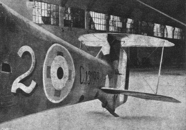
Three-quarter front view of the biplane tail of the Hannover.
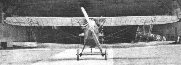
Front view of the Hannover biplane.
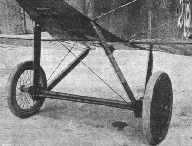
The undercarriage of the Hannover biplane.
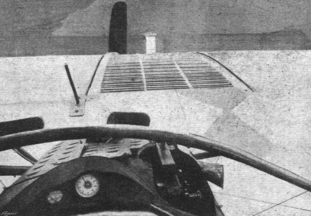
View of the radiator of the Hannover.
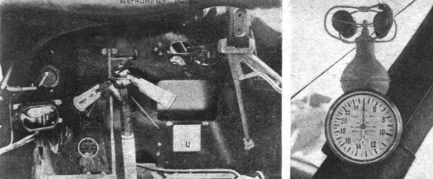
Instrument board and control handle of the Hannover biplane. On the right the air-speed indicator, which is mounted on an inter-plane strut.
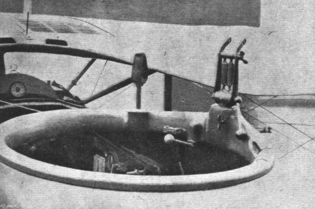
The gun ring of the Hannover biplane, showing lock.

THE HANNOVER OR "MYSTERY" BIPLANE. - Three-quarter front view of the body. The chief feature of this machine, apart from the biplane tail, is the enormously deep fuselage, built in the usual German fashion, of a light framework covered with three-ply wood.

THE HANNOVER OR "MYSTERY" BIPLANE. - Two views of the biplane tail. The elevator of the lower tail plane, it will be noticed, is divided, while the upper elevator is carried right across from side to side. The two elevators are interconnected by a vertical rod inside the fin, joining the cranks of upper and lower elevators.
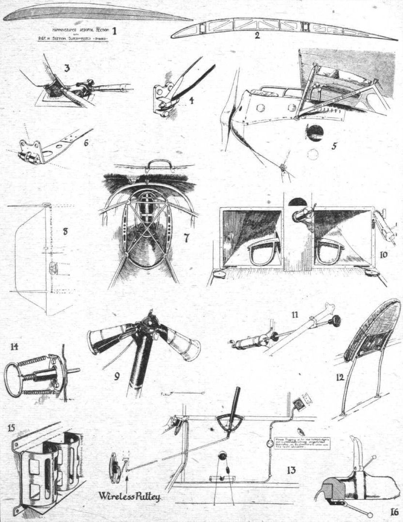
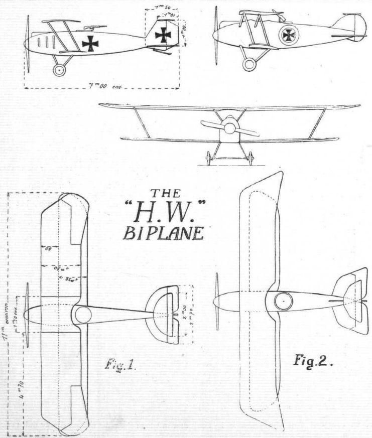
DIAGRAMMATIC RECONSTRUCTION OF THE GERMAN "H.W." BIPLANE. - Fig. 1, as reconstructed from wreckage. Fig. 2, as observed by Lieut. Mussat.
These sketches were published in l'Aerophile and Flight magazines showing the "Mystery German Biplane."
These sketches were published in l'Aerophile and Flight magazines showing the "Mystery German Biplane."
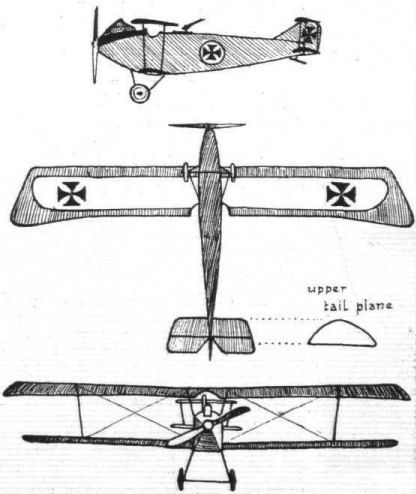
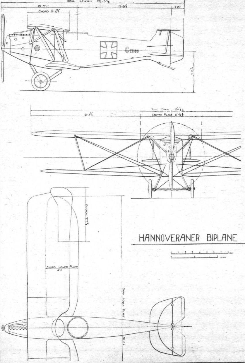
Flight, January 17, 1918.
FROM OTHER LANDS.
AUSTRIAN AGO AND LOHNER FLYING BOATS.
("Aerial Age," U.S.A., from material supplied by the U.S.A. Government.)
Two types of Austrian seaplanes which have fallen into the hands of the Italians during the present year, and regarded as worthy of special note, are the Ago and Lohner types. The Ago Sea-Pursuit Biplane described here and shown in the accompanying line drawing, bore the number "A-25"; it was captured May 18th, 1917. The Lohner-type flying boat (described later in this article) was brought down on the night of January 12th, 1917, and it was marked " K-301."
1.- The Ago Sea-Pursuit Biplane.
In its general lines this machine does not differ much from all the flying boats of the Ago type. It does offer, however, features that are original and worthy of mention. Most striking is the structure of the wing cell in which no wires are employed.
The wing cell may be considered as consisting of two cross-networks, each made up of a front spar and a rear spar and of adjacent struts in inclined planes connecting the spars, all converging toward the centre of the "star" located midway between upper and lower wings. The struts are of polished steel tubing with a fairing of laminated wood less than one mm. thick, providing a good streamlining effect.
General Dimensions.
Span, upper plane 8.00 m
Span, lower plane 7.38m
Chord, both planes 1.50 m
Gap between planes 1.65 m
Length overall 7.62 m
Length of hull 6.50 m
Maximum width of hull 1.00 m
Motor, Warschalowski 218 h.p
Propeller, diameter 2.72 m
No lists of weights or performances are obtainable. The accompanying sketch will give an idea of the appearance of the "A-25" in flight.
Control cables to the ailerons pass close to the struts of the turret and lead to the upper plane. Each aileron is about 1.40 m. long and .40 m. wide.
The construction solution of the hull, the great care with which the exposed parts have been shaped, the complete covering of the cables and control wires, and the streamline shape of the hull, all show a desire to cut down head resistances as much as possible. Similar care is shown in all details of construction to reduce to a minimum the weight of the machine without detriment to its strength.
The hull is 6 1/2m. long; width at the step, .95 m.; maximum width, 1 m.; distance from bow to step, 3.45 m.; height of step, .16 m. The shape of the body with the necessary lining at the bow and because of a careful laying of the side and bottom plating approaches very much the shape of a solid body of fairly good streamline form. The wing floats are spaced 5 m. apart. They are of streamline section, with flat sides, attached to the planes by means of one forward strut and two rear struts, with cross wire bracing between the struts.
The empennage or tail group is 2.38 m. in span, sustained in front by a vertical fin of very thin laminated wood, by two stays and two wire cables. Control wires of rudder flaps or elevators run through the fin. The rudder is 1.40 m. high by .80 m. wide.
The data given out concerning the motor is as follows :- "Motor: Hiero Flugmotor, Osterr; Ind. Werke Warschalowski, Eissler & Co.; A-G 6 cylinders; type, HN1096. It develops 218 h.p. at 1,400 revolutions per minute. Weight 314 kilograms. It is equipped with Bosch magnetos and small starting magnetos. Propeller: 2:0 h.p.h. Hiero 6 cylinders; diameter, 2.72 m.; pitch, 2.25-2.40.
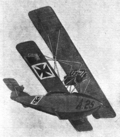
Sketch showing the Austrian Ago Sea-Pursuit flying boat "A-25,'' in flight.

THE AUSTRIAN AGO TYPE PURSUIT FLYING BOAT. - Plan, side and front elevations to scale.
Flight, 1918.
The diminutive machine on the picture is the private venture fighter designed by Dipl.-Ing. F.D. Hergt in 1918. The machine was actually built by the Fliegerersatz-Abteilung (F.E.A. 1) in Altenburg (Thuringen). An amazing feat that he could persuade the authorities to allocate precious resources and labour to this private venture.
The resources were by the way very old-fashioned , given a 80 hp Gnome rotary (or the Oberursel 'licence' equivalent ?).
The claim to fame of this machine was at least that is was flown by Mario Scherff who flew it as a test pilot.
By the way Scherff was not very lucky in WW1 as he crashed as a Fokker test pilot with a Fokker M.7 (to be delivered to Austria) on 17 April 1915, luckily coming out of it alive. He spent a more than a year in the hospital at Schwerin. Fokker was not the most likable boss because a few days after the crash he fired Scherff and he never paid any visit to the hospital. After that (end 1916) Scherff started again as a test and acceptance pilot with other firms.
Flight, November 28, 1918.
THE JUNKER ARMOURED BIPLANE
FOR some time past there have been rumours current of a German all-metal aeroplane in which, it was said, even the wing covering was of metal. It is not, however, until quite recently that we have been able to obtain reliable information concerning this machine. What is left of the Junker biplane, as the machine in question is called, is now included among the many interesting exhibits at the Enemy Aircraft View Rooms at the Agricultural Hall, Islington, where our representatives have been permitted to examine this machine in detail.
Owing to the damaged condition of the specimen on view it has not been possible to give, this week, more than a brief outline of the main characteristics of the machine. Later we hope to be able to describe it in more detail.
The Junker armoured biplane is designed for use as a trench fighter, and in contradistinction to the A.E.G. armoured biplane it was evidently designed with this object in view from the start, the armour not being attached, as a supplement, to an ordinary girder structure, as was the case with the A.E.G., but forming the main fuselage structure at the same time as providing the armouring.
The shape of the front portion of the fuselage may be seen in one of the accompanying photographs. It has flat sides of armour plating, and a slightly curved top of aluminium. The bottom of the body is formed of three fiat surfaces, the middle one of which is horizontal, the other two sloping so as to connect the edges of the horizontal bottom with those of the vertical sides. The engine, a 230 h.p. Benz, is also protected by armour plating, which is detachable so as to allow access to the engine. This is accomplished by hinging the armour at this point, the port and starboard engine armour being separately detachable. In the accompanying photograph the engine armour of one side will be seen lying on the floor in front of the fuselage. The armouring is finished off just behind the gunner's cockpit, where it is continued across the fuselage by a curved armour plate shaped to form the gunner's back rest.
Of the rear portion of the fuselage nothing remains on the machine examined, and nothing can therefore be said regarding the details of its construction. Judging from such evidence as fittings for large diameter tubes at the four corners it would appear that the rear part of the fuselage has been built up of a tubular framework of Duralumin.
The wings of the Junker are of great interest as being of a construction very dissimilar to any so far seen. The internal construction of the wings is in the form of Duralumin, tubes crossing diagonally and connecting the tubular spars, which latter are far greater in number than is ordinarily found in an aeroplane wing. It has evidently been the aim of the designer to distribute the spars over the wing section rather than to provide two spars located in the usual manner. In the Junker there may be said to be six spars if one counts the top and bottom tubes lying vertically above one another as one spar. The lower photograph will give some idea of the general distribution of the various wing members.
In section the planes of the Junker are enormously deep, the maximum thickness of the top plane being about 16 in. The chord of this wing is a little over 8 ft. while the chord of the bottom plane is approximately 5 ft.
From the fact that no trace was found of inter-plane strut fittings it would appear that these members have been dispensed with in the Junker. It appears that the top plane centre-section was carried on a structure of tubes from the body, while the bottom plane appears to have been attached to the bottom of the fuselage by a series of diagonal struts. This arrangement, which would be made possible by employing such a deep wing section, would have the advantage that the gunner could fire forward at a considerable angle without danger of hitting a vital member of the wings.
The undercarriage is in the form of two Vees, attached to the lower plane some distance out. From this point the bracing tubes of the bottom plane run to the body, thus transmitting the shock to the fuselage without, presumably, causing excessive bending stresses in the lower wing spars.
The wing covering is in the form of corrugated aluminium sheet, and it was noticed that this did not form a fair curve over the wing framework, but was rather in the nature of a series of straight lines. This could hardly improve the aerodynamic qualities of the wing section, but on the other hand it is possible that the effects are not great. Later we hope to be able to give some details of this interesting machine.
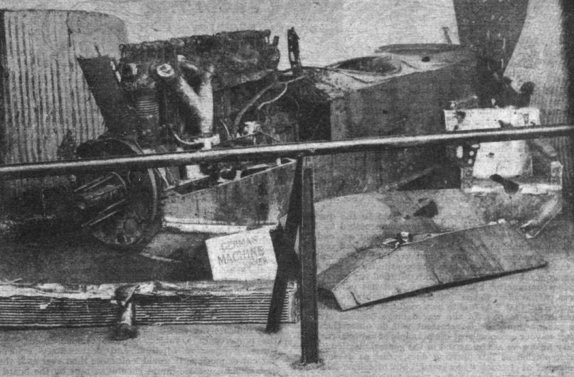
THE JUNKER ARMOURED BIPLANE. - Front portion of fuselage, with engine.
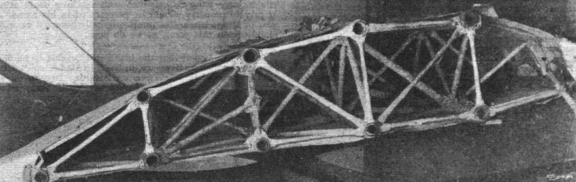
THE JUNKER ARMOURED BIPLANE. - End view of top-plane centre-section.
Flight, July 11, 1918.
THE ROLAND SINGLE-SEATER CHASER, D. II.
THE single-seater Roland biplane, D. II, which made its first appearance about March, 1917, is still frequently encountered by our pilots, especially on the Eastern sectors. It has therefore seemed to us of interest to give a description of it with detailed drawings. The dimensions of the Roland D. II are very small :-
Span of upper plane 8.90 m.
Span of lower plane 8.50 m.
Length overall 6.95 m.
Height 2.95m.
Its weight - 827 kilogs. - with full tanks is slightly greater than that of the Albatros D. III chaser. The lifting surface being 23 sq. m., the wing loading is 36 kg./sq. m. (7.2 lbs./sq. ft.).
Fuselage.
The construction of the fuselage, and its peculiar shape, merit special attention. Being built entirely of three-ply wood and covered with fabric, it is of the monocoque type, of oval section, and terminates at the stern in a vertical knife edge. The construction is excessively light, the framework consisting of very thin longerons running through the whole length of the body, the curves of which they follow. Rigidity is only provided by the ply wood, made in two halves joined along the middle of the top and bottom. The total thickness of the six layers is only 1.5 mm. From the pilot's seat to the tail there are only four formers of very small thickness.
Between the pilot's seat and the motor the fuselage forms a projection tapering upwards to form at its upper extremity an edge 0.11 m. wide, to which are attached the radiator and the top plane. The top plane is cut away to accommodate the radiator. This arrangement of an upward projection of the body itself takes the place of the cabane. On the lower part of the fuselage, and built integrally with it, there are the roots to which the two halves of the lower plane are attached. At the rear the tail skid, of wood with a shoe of metal, pierces the fuselage, and is supported on a projection of ply wood similar to that employed on the Nieuport.
The pilot is placed very high, and has in front of him two wind screens, one on each side of the central structure carrying the upper plane. The view in a forward direction being thus divided would appear to be inferior to that obtainable in other types of machines.
Planes.
The planes are of trapezoidal plan form, of unequal span, without stagger and dihedral angle, but with a sweep-back of 1.50. The chord, which is uniform, is 1.45 m. and the gap 1.34 m. The ribs are at right angles to the leading edge. As the inter-plane struts are secured to the spars over the same rib, it follows that in the front view the struts do not come quite in line. The spars of the upper plane, which are of spruce, are spaced 0.83 m. apart, the front spar being 0.13 m. from the leading edge. The ribs, of which there are 12, are of I section with flanges of ash. They are spaced about 0.37 m. apart. In the middle of each interval there is a false rib running from the leading edge to the rear spar. In each wing there are four compression members in the form of steel tubes 25 mm. diameter. These tubes are evenly spaced, the distance between them being 1.30 m., and are braced by 3 mm. piano wire. Between the front spar and the leading edge there are two tapes running parallel to the spars and crossing alternately over and under consecutive ribs. Two more tapes are similarly arranged between the spars. Certain corners are stiffened by reinforcement with ply wood. Each of the upper planes carries an aileron, which is not balanced and of equal chord throughout. A strip of three-ply wood, under the fabric, covers and protects the hinge fixed on the rear spar. The aileron measures 1.82 m. in length and has a chord of 0.42 m. Its leading edge is a steel tube of 30 mm. diameter. The aileron cranks are operated, as in the Nieuport, by two vertical tubes. In the left top plane is mounted a petrol service tank. Openings in each of the halves of the top plane accommodate the radiator. The upper planes are attached direct to the highest portion of the fuselage by means of special bolts resembling somewhat those used on the L.V.G. C. IV.
The lower planes are constructed in much the same manner as the top ones. The spars are similarly arranged and are consequently the same distance apart. In each wing there are 10 ribs, of which nine measure 0.01 m. and the last one 0.025 m. Between the ribs are false ribs measuring 10 mm. The internal wing bracing is the same as that of the top plane, but the distribution of the four steel tube compression struts (of which one is 20 mm. and the others 25 mm.) is somewhat different. From the first to the second is 1.17 m., from the second to the third is 1.13 m., and from the third to the fourth 1.11 m. The lower planes are attached to wing roots built integrally with the fuselage. The angle of incidence is 4# at the second rib and 3# at the seventh. The inter-plane struts are in the form of steel tubes 0.025 m. diameter, stream-lined with a wood fairing which brings their depth to 0.09 m.
The Tail.
The shape of the tail can be seen from the plane view of the machine. The fixed tail plane is built of wood, while the two elevator flaps are constructed entirely in metal.
A note should be made of the attachment of the tail plane to the body. The leading edge of the tail plane is hollowed out, and into the hollow space thus formed fits a piece of wood which runs across the fuselage and the ends of which project 0.50 m. on each side. Further rigidity is given to the structure by two stream-line tubes running from the tail plane to the rudder hinge on the vertical fin. The rudder, which is roughly rectangular with rounded corners and has a forward projection for balancing, is built up of steel tubes, while the fin, which is made integral with the body, is of three-ply wood.
The elevator cables, which are attached to a central crank lever, are enclosed inside the body except for the last meter or so from the stern.
Engine.
The engine fitted on the Roland D. II is a 160 h.p. Mercedes six-cylinder vertical engine. The exhaust collector is nearly horizontal, and is placed on the starboard side. In addition to the gravity tank in the top plane there is a main petrol tank measuring 70x70x25 under the rudder bar. The airscrew having been smashed it has not been possible to identify it. It had its boss enclosed in the usual "spinner."
Armament.
Two fixed Spandau guns are operated by the motor. They are mounted one on each side, and do not project through the fuselage covering until just at the extreme front.
Undercarriage.
The undercarriage is formed by two pairs of Vee struts, braced diagonally by two crossed cables. Their attachment to the fuselage occurs at two sloping formers. The axle, which is placed between two cross <...> is enclosed in a stream-line casing. The track <...>.75 m. The wheels measure 760 by 100. The shock absorbers are of rubber.
It has been said of the Roland D II that owing to its light construction the fuselage is apt to get out of shape, and that it has a tendency to spin. As up to the present no test of this machine has been possible, our opinion can only be based on the testimony of our aviators. From this it appears that this machine, of new conception, must be counted among the best of German chasers. The Roland D. II single-seater, enters still into the composition of certain enemy squadrons.

Roland D.IIa, at Adlershof during Winter 1916-1917
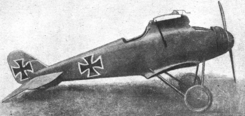
The curious body of the German Roland single-seater chaser biplane. The centre sections of the wings are left in place, and show where the planes are attached. The top plane, it will be noticed, is attached to the top of the fuselage. Note the balanced rudder and elevators.
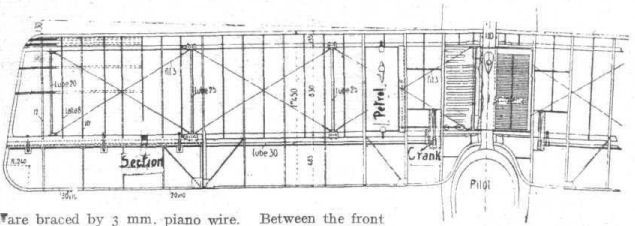
The upper plane of the Roland D. II.
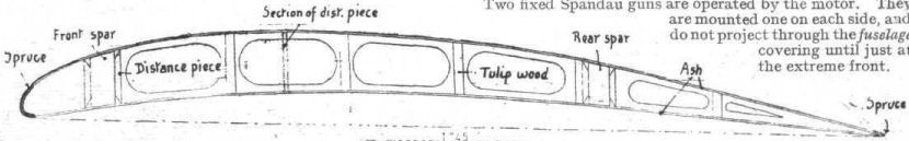
One of the main plane ribs of the Roland D. II.
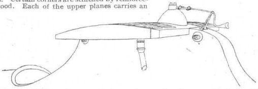
Diagram of "bump" supporting top plane and radiator on the Roland D. II.
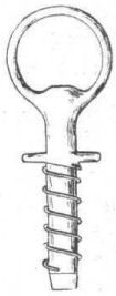
The quick-release bolt for attaching main planes on the Roland D. II.
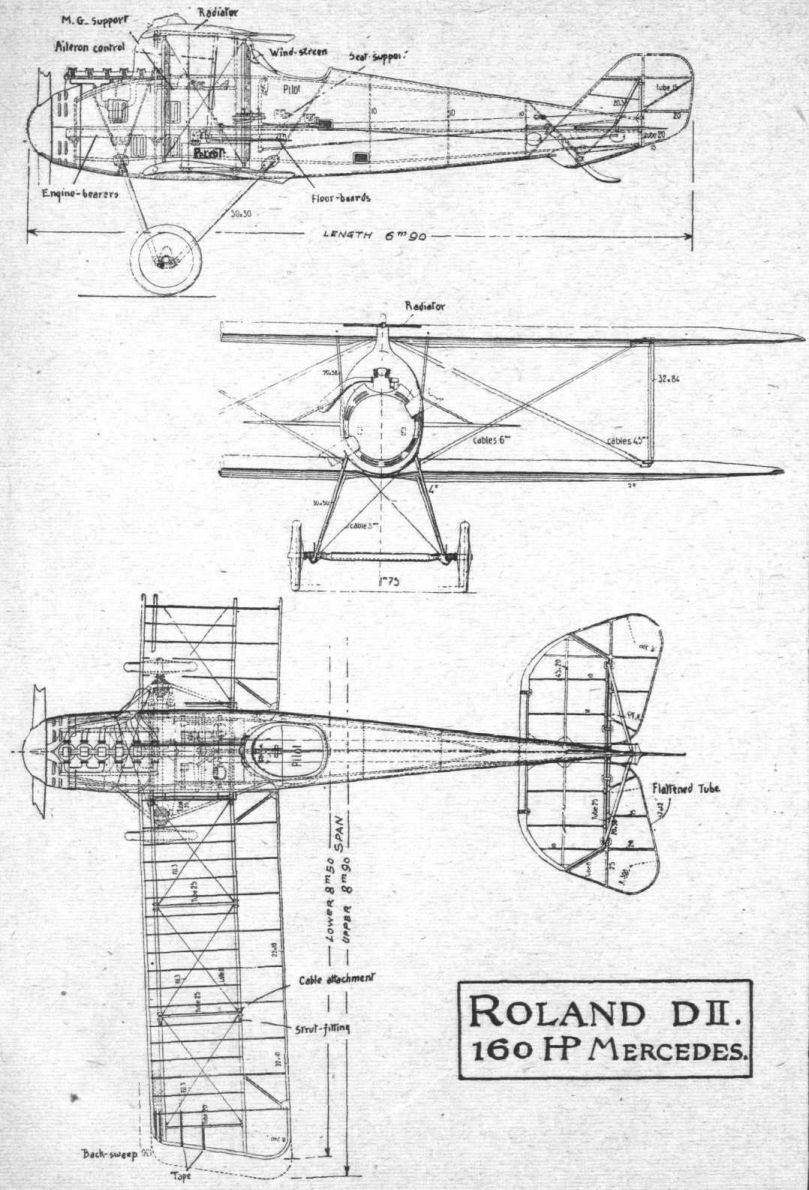
THE ROLAND SINGLE-SEATER CHASER, D. II. - Plan, side and front elevations to scale.
Flight, June 6, 1918.
THE GERMAN L.V.G. BIPLANE, TYPE C.V.
THE L.V.G. biplane, which is built by the Luft Verkehrs Gesellschaft, is a two-seater, belonging to the C class (general utility machine). It is slower than the C. IV type Rumpler, its climb is not so good (4,000 metres in 35 minutes), and its ceiling is lower (slightly over 5,000 metres). The speed is: At 2,000 metres, 164 kiloms.; at 3,000 metres, 160 kiloms.; at 4,000 metres, 150 kiloms.
The following are comparative tables of the different types of L.V.G.'s and the L.V.G. C. V and Rumpler C. IV :-
L.V.G.'s. Rumpler.
Type ." C.II C.IV C.V Type C. IV
Span (upper) 12.85 13.60 13.62 12.60
Span (lower) 11.35 12.00 12.85 12.10
Length overall 8.10 8.60 8.10 8.40
Height 3.00 3.10 3.20 3.25
Lifting surface sq. m. 37.60 40 42.70 33.50 sq. m.
Weight kilogs. 845 900 920 1.010
Engine power 175 h.p. 235 h.p. 225 h.p. 260 h.p.
Make Mercedes Mercedes Benz Mercedes or Maybach
Both upper and lower wings are set at a dihedral angle, that of the upper -wing being 1°, and that of the lower 2°. There is no stagger and no sweep-back. The trailing edge is flexible. The ribs are spaced about 40 cm. apart, with false ribs in between. The incidence has been found to be as follows: First and second ribs, 4 1/2°; third to ninth ribs, 5° ; tenth rib, 4 1/4° ; eleventh rib, 4 1/2° ; twelfth rib, 4° ; thirteenth rib, 3°.
In plan view the upper wings are of slightly trapezoidal form, with rounded corners. Their chord is 1.74 m. In the centre there is a semi-circular portion cut away. The wing flags project 34 cm. beyond the wing tip, and have rounded tips somewhat resembling those of the Gothas. Their total length is 2.61 m. Their chord varies from 53 cm. at the root to 75 cm. at the outer end. The wing flap hinges are parallel to the leading edge. The attachment is by means of keyed bolts, of which we give a diagram. This system was employed for the wing attachment on the Roland chaser D. II. It has the advantage of being easy to attach and dismantle.
The lower wings have, following present German tendency, rounded corners, with the trailing edge shorter than the leading edge, as in the D.F.W., Rumpler C. IV, and Albatros C. 10. The maximum chord is 1.59 m. The wing flap control cables pass through the interior of the lower planes. The inter-plane struts (two pairs on each side of the body) are of wood and streamline in section, the depth being 0.105 m., and taper towards the ends. Owing to the difference in dihedral angle the inner and outer struts are not of the same length. The length of the inner struts is 1.635 m., and of the outer 1.59 m. The gap is 1.74 m. at the body and 1.66 at the outer struts. The total wing surface is 42.270 m., the area of the top plane being 23.260 m., and that of the bottom plane 19.210 m. The cabane is composed of two pairs of N's sloping backwards and inwards.
The tail plane resembles that of the Albatros chasers, but it will be noticed that the leading edge is much flatter and the plane of smaller chord. The two halves of the tail plane are attached to portions fixed to the body, and which, like the body, are covered with three-ply. The elevator is in one piece and has rounded corners. It is balanced by triangular forward projections at each end. The maximum span is 3.04 m., and the chord 0.65 m. The small triangles have a base of 0.39 m., and a height of 0.39 m. The balanced rudder is placed above the elevator, and forms with the fin an oval sloping backwards. The fin is of three-ply and is of trapezoidal form. The total height of the vertical tail members is 1.068 m. The chord is 0.675 m. (1.15 m. including balancing portion). The internal structure of the tail organs is in the form of metal tubes. The control cables pass into the body at a point 1.50 m. from the stern post. One of the elevator cables passes through the tail plane.
The body is entirely in three-ply wood, with flat sides and with deeply curved top and less curved bottom. The general lines of the body are less tapered than those of the Rumpler C. IV. The air screw is a "Garuda" of 3.04 m. diameter. The boss is encased in a "spinner."
The engine is a 225 h.p. Benz, of the same type as that employed on the D.F.W. and F.D.H.G. II. The motor is supplied with petrol from two tanks of a capacity of 249 litres. On the left top plane is mounted a service tank. The tanks contain fuel sufficient for a flight of 3 1/4 hours' duration. The upper portion of the engine is totally enclosed in a metal cover, which can be detached from the body. The exhaust is carried away upwards as in the Rumpler, but the exhaust collector is only slightly curved and is nearly vertical.
The radiator, which is of the honeycomb type, has a capacity of 35 litres. It is mounted in front of the top plane, on brackets from the front legs of the cabane. Its upper part is braced, by means of a small steel tube fork, to the upper plane. The shutter in front of the radiator is one of the best adopted on German machines. It is simpler than those of the slat system. It consists of a movable blind of strong fabric, which can be rolled up or unrolled at the will of the pilot, thus permitting of obstructing the passage of the air and varying the cooling.
The pilot's cockpit - behind the engine - is of oval shape, its greatest dimension being from front to back. Close to it is the passenger's cockpit, with a gun ring of 0.60 m. diameter, which carries a support from the Parabellum machine gun. This support resembles those employed on certain of our machines. In front, and on the right hand side, is a fixed machine gun of the Spandau type, fitted with the usual interrupter gear worked by the engine. The gun is fired via Bowden cable. A wireless outfit is carried on board.
The under-carriage is of the Vee type, with streamline struts of wood. There is one pair of wheels, measuring 0.810 m. by 0.125 m. The tyres are stamped "Harburg," of Vienna.
The track is 1.98 m. The axle is enclosed in a streamline casing of wood, having a width of 0.20 m. The shock absorbers are in the form of "Sandows." As in the Rumpler C. IV, the rear inner inter-plane strut is braced to the nose of the body by a cable.
The tail skid, which is mounted on a small fin under the body, is of wood, and terminates in four laminations of steel 0.002 m. thick. The last lamination is reinforced with a steel shoe.
The machine is camouflaged in light green and mauve as regards the upper surface of the planes and the tail plane. The lower surface of the wings is painted light blue. In the passenger's cockpit there is an opening in the floor accommodating a camera, and the machine appears to have been intended for photographic reconnaissance work. There is no bomb gear.
Flight, December 19, 1918.
THE L.V.G. TWO-SEATER BIPLANES
[Issued by Technical Department (Aircraft Production), Ministry of Munitions]
THIS report is concerned with two L.V.G. biplanes, of which one is of the C.V. type, while the other, a C.VI. type machine, is of later design, embodying certain alterations and improvements. The C.V. machine is allotted G/3Bde/5, and the C.VI. which was brought down near Proven on August 2nd by two S.E. 5's, piloted by Lieuts. Gordon and Gould, is alloted G/2 Bde/21.
Any description which follows and is not definitely stated to apply to either model, must be read as appertaining to the C.VI type.
The C.V. machine was only slightly damaged, and has been put into flying order, but the C.VI. has suffered severely, and it must be stated that on this account the G.A. drawings are not guaranteed to be of absolute accuracy in every respect. The greatest care has, however, been taken in their preparation, and only features of rigging such as dihedral and stagger (besides the tail planes, which are in a very fragmentary condition) are at all doubtful. In matters of detail the drawings are accurate.
Some leading particulars of both machines are given below :-
C.V. Type. C.VI. Type.
Weight empty 2,188 lbs. 2,090 lbs.
Total weight 3,141 lbs. 3,036 lbs.
Area of upper wings
(with ailerons) 238.4 sq. ft. 196.0 sq. ft.
Area of lower wings 190.4 sq. ft. 160.0 sq. ft.
Total area of wings 428.8 sq. ft. 356.0 sq. ft.
Loading per sq. ft. of
wing surface 7.3 lbs. 8.5 lbs.
Area of aileron, each 13.6 sq.ft. 11.2 sq. ft.
Area of balance of
aileron 0.4 sq. ft. 0.0 sq. ft.
Area of tail plane 21.6 sq. ft. 28.0 sq. ft.
Area of fin 5.2 sq. ft. 5.2 sq. ft,
Area of rudder 6.8 sq. ft. 6.8 sq. ft.
Area of balance of
rudder 0.6 sq. ft. 0.6 sq, ft.
Area of elevators 20.8 sq. ft. 16.0 sq. ft.
Area of balance of
elevator (one) 1.2 sq. ft. 0.8 sq. ft.
Total weight per h.p. 13.7 lbs. 13.2 lbs.
Crew 2 - Pilot and observer.
Armament 1 Spandau and 1 Parabellum
gun.
Engine 230 h.p. Benz.
Petrol capacity 52 1/2 gals. 52 1/2 gals.
Wings.
There are several important differences between the arrangement of main planes of the two models, as will be seen by referring to the G.A. drawings.
The wings of the C.V. L.V.G. are without stagger, and are not swept back, but both upper and lower planes are set at a dihedral angle, this being 1° for the upper, and 2° for the lower wings. The lower planes are smaller all round than the upper, and have rounded tips. The upper planes only have ailerons, which are of equal chord throughout their length, and are balanced. These planes also follow what was, until recently, the usual enemy practice, by being joined at their roots to a central cabane. There is, therefore, no horizontal centre section in this aeroplane, except for the 3-ply box (about 4 in, wide), which surrounds the horizontal tube of the cabane. For improving the view, the upper plane is cut away over the pilot's cockpit. Relative to the crankshaft the upper wing has a constant angle of incidence of 5°. That of the lower wing is the same, except at the tip, where the angle is washed out to 4°, and at the root to 4 1/2°.
Both upper and lower wings are attached to the body by the same general means, this being adapted to the particular positions and conditions of each joint. In the case of the upper planes, the cabane has lugs welded to its upper side at both ends. Fig. 1 shows the fitting at the forward end, and the pierced lug on the wing spar (see Fig. 2) fits into the fork. The same type of hinge pin is used for all wing joints, and for the aileron hinges also. It consists of a short length of steel tube, carrying at one end some form of stop, and at its other end a slot in which a short rectangular piece of steel is free to rotate, the steel piece being pivoted at its centre. Thus, when the steel piece is placed parallel to the tube, the whole fitting can be passed through any hole which will accommodate the tube, but when the piece is placed at right angles to the tube axis, the tube cannot be withdrawn through a small hole. A helical spring ensures that the steel piece shall be pressed against the hole, and not be free to slip into the parallel position.
The lower wing attachments are very similar, as will be gathered from Figs. 3 and 4, which show respectively the front and rear joints, and this plan has not been changed on the C.VI. type of L.V.G., except that the lug on the wing spar is now fashioned as shown in Fig. 5.
In the later model - the C.VI - the planes are of the same general shape, but important changes are remarked. The radiator has been moved from the position it occupied on the C.V. (see G.A. drawings), and is now built into the horizontal centre section. It is, of course, common German practice to build the radiator into the upper plane, and such a position is not incompatible with the cabane type of centre section strutting. This is particularly true when-as is the case in the. L.V.G.-a service petrol tank is supported by the upper plane, and can be made to balance the radiator. It is clear, therefore, that the alteration in design from the cabane system to the centre section system has not been made solely to accommodate the radiator.
So far as may be judged from the machine in its present condition, the C.VI has a positive stagger of 10 in., and both upper and lower planes have a similar dihedral angle, viz., 1°. Ailerons are still fitted to the upper plane only, but are not balanced in this model. The upper and lower wing sections of the C.VI. model are shown in Fig. 6, and Fig. 7 gives the C.VI. upper wing section with the R.A.F. 14 section superimposed. The R.A.F. 14 section is dotted.
(To be concluded.)
Flight, December 19, 1918.
THE L.V,G. TWO-SEATER BIPLANES
[Issued by Technical Department (Aircraft Production), Ministry of Munitions.]
(Concluded from page 1431.)
Wing Construction
(THESE details were all noticed in the C.VI. machine, as in the earlier type the planes are still covered with fabric.)
Both front and rear spars are of the box type, and wrapped with fabric. Sections drawn to scale are given in Fig. 8, but these drawings do not show internal construction, as the spars have not yet been divided.
The overall height and width of each spar, taken respectively parallel and perpendicular to the vertical walls, are :- Upper plane, front spar, height 3 1/4 in., width 1 7/16 in.; rear spar, height 3 in., width 1 15/16 in.; lower plane, rear spar, height 3 in., width 1 11/16 in.; front spar, height 2 7/8 in., width 1 11/16 in.
It has been possible to draw a section of the front spar of the C.V. machine, and the result is given in Fig. 9. There is every reason to believe that all the other spars of the L.V.G. are of similar construction. Fig. 10 shows a crude but effective method of repairing a broken spar. The repair was carried out by the enemy, probably in the field.
The leading edge is of the customary C section, and is followed at 7 in. interval by the front spar. The space between the two spars - 25 3/4 in. wide - is braced with cables and piano wire, and contains four ash compression struts of I section, which are simply butted into sockets obviously intended to carry steel tubes. (These compression struts are steel in the C.V. model.) The distance from the rear spar to the wire trailing edge is 2 ft. 6 3/8 in. The ribs, of which a section is shown, are of the usual type, and are spaced at intervals of 16 3/4 in., centre to centre. They are unlightened. Equally between them are placed two false ribs - mere strips of wood let into the leading edge and tacked to the spars. These false ribs have floating ends 7 1/2 in. behind the rear spar.
The construction of the lower plane does not differ from that of the upper plane just described, except that the false ribs are not found in it.
Ailerons
The ailerons of the L.V.G. no longer possess the peculiar step in the trailing edge that has for so long been associated with the design, and the ailerons are rather different in the two types. The C.V. model has ailerons which are balanced while those of the C.VI. are not. The respective areas are given on the first page of the report. With regard to the constructional features, only those of the later type can be described. The whole construction is of wood, with the exception of the aileron lever, a sketch of which is given (Fig. 11). This is of the usual curved type in the C.V. machine (see Fig. 12), but is made to serve as a rib also in the C.VI. type. The wooden ribs, together with the wood leading and trailing edges, form a structure which is very light. Both machines have the ailerons hinged to a false spar some distance behind the rear spar, and the hinges are all of the type that has already been described in connection with the wing attachments (see Fig. 13).
Struts
The L.V.G. is one of the few enemy aeroplanes that employ interplane struts of wood. They are of the shape shown in, Fig. 14, and are of streamline section (2 1/4 in. x 1 9/16 in.), slightly hollowed out for lightening purposes. Fabric is wrapped round the strut in three places, and the form of the strut sockets is made clear in the sketch (Fig. 14), which shows one of the C.V. struts.
The types of strut socket employed in the C.VI. machine is shown in Fig. 15, while Fig. 16 shows how the strut is attached to the spar. The socket is held in place on the strut by simply inserting a suitable length of steel tube through a drilled hole in socket and strut and riveting over the ends.
As has already been mentioned, the centre section struts are different in the two types. In the C.V. machine the cabane, the shape of which is made clear by the G.A. drawings, is made of streamline steel tubing. This has been changed, and the C.VI. model has parallel centre section struts of wood, which are like the letter N when seen from the port side. Fig. 17 shows the pint between the spar of the centre section and the strut. The unusual arrangement of the cross-bracing of this centre section should be noticed in the front view, G.A. drawings.
The line of the front limb of the N is carried on by the third fuselage bulkhead, and finishes at the front joint of fuselage and undercarriage. The angle between the rear two limbs of the N is practically bisected by the line of the fifth bulkhead, which finishes at the rear joint of fuselage and undercarriage. This is shown by a diagram, Fig. 18. The C.V. machine has a sloping steel tubular strut between engine bearer and rear undercarriage attachment (see Fig. 19), but by the rearrangement of bulkheads the necessity for this has vanished, and the strut is not found in the later model.
Fuselage
The earlier types of L.V.G. had bodies built on the cross-braced girder system. Both the machines described possess the same type of fuselage, totally different from the girder system, viz., a framework of bulkheads and longerons, covered with a thin layer of 3-ply and totally without wire bracing. Fig. 20 gives the number of shapes of the bulkhead in the C.V. machine, and incidentally reveals the shape of the fuselage. The C.VI. type has generally the same arrangement, but the third and fifth, bulkhead are no longer vertical in this model, and the tail part of the body has been strengthened by the insertion of another cross piece.
Although the fuselage of the L.V.G. biplane ends in a vertical wedge, the provision of a centre section for the tail plane gives a cruciform appearance to this part. This is shown clearly by Fig. 21, where the two sides of the tail plane centre section are drawn in thin lines. The 3-ply covering to the fuselage rounds off the joint of body and tail plane in the neat way that is found in so many German aeroplanes. (See Fig. 22.)
Tail
The shape of the fixed tail planes is shown in the G.A. drawings. The main box spar (see dotted section in Fig. 21) passes right through the body. The rear spar, to which the elevators are hinged, is of rectangular section wood, hollowed on its rear face to take the steel tube which serves as the elevator spar. The tail is so badly damaged that detailed analysis is impossible, but the fixed tail planes are of wooden construction, with the usual ribs and semicircular leading edge. It will be noticed that the tail plane is not set parallel to the crankshaft line, but is raised through an angle of 5°, and it has a symmetrical streamline section.
The elevator, which is balanced and undivided in both models, is a welded structure of light steel tubing, and presents no unusual feature. There is a small protecting horn provided on the tail plane, to prevent damage to the corner of the balanced portion of the elevator - Fig. 23 gives a clear idea of this example of thoroughness.
The tail skids are both of the same general type as that of the Pfalz Scout, i.e., the member is entirely exposed, and does not project into the fuselage. It is of ash, and the upper end is so shaped as to avoid the necessity for any metal link or fitting. Both machines also have a small triangular fin on the underside of the fuselage which serves the double purpose of providing fin area and of adapting the shape of the fuselage to the slope required for the tail skid. (See Fig. 22.)
It will be seen from the sketch (Fig. 24) that the skid of the C.V. machine carries a four-leaved fiat spring bolted a little to the rear of the pivot. In the later model this has been discarded. The shape of the lower triangular fin also differs slightly - that of the C.VI. has been simplified and strengthened. The workmanship of the sheet steel angle piece on the C.VI. machine gives one the impression that it is a "squadron fitting." It is of fairly heavy gauge, and may have replaced a weaker part fitted by the manufacturer.
Undercarriage
The landing gears of both machines are similar, and in general arrangement conform to the practice that is now practically standard. The vee struts are of streamline section, and constructed of fabric-covered wood. The practice of using wood for undercarriage struts is, of course, unusual in enemy machines, but is in conformity with the other struts - interplane and centre section - on this machine.
The major and minor axes of cross section of one of the front struts (and all four, front and rear, are of equal dimensions) are respectively 2 9/32 in. and 4 7/8 in.
The upper and lower extremities are capped with steel sockets, which allow of attachment to the fuselage at the upper extremities and at the lower ends serve to connect the two limbs of the vee, and are provided with accommodation for the shock absorber. Figs. 25 and 26 show respectively the component parts of the attachment to the fuselage, and the socket at the lower part of the vee. From Fig. 25 it will be noticed that the ball at the head of the strut beds into a hemispherical socket attached to the fuselage. The lower half of the ball articulates with a curved surface on the ferrule, and the ferrule next slipped over attachment. In assembling this joint - and this is a matter of seconds only - the ball is first passed through the opening provided on the ferrule, and the ferrule next slipped over the body lug and pinned in place. All four body attachments are of this type in the C.VI, machines, but in the C.V. model the joint was made by simply pinning the ball to its socket, without the refinement of a ferrule.
The shock absorber is of the coil spring type, with three small diameter springs lying side by side, as indicated in Fig. 26. A loop of cable limits the amount of axle travel, and between the lower extremities of the vees is a steel compression tube, of 1 1/2 in. O.D., and behind this lies the axle, which is encased in a 3-ply fairing. It will be noticed that the compression tube is not included in the fairing, and when the axle is raised as the machine lands, the fairing travels with the axle. This method allows of good accessibility to these components, but is not quite so good an arrangement from the streamline point of view as the common method of allowing the axle to lift out of a fixed fairing.
The schedule of principal weights, given at the end of this report, is of considerable interest as regards the undercarriage.
The wheels are 810 x 125, and the track 6 ft. 7 in. The cross bracing does not start from either front or rear fuselage attachments, but from the front spar joint on the fuselage.
Controls
As is the case throughout the design, the controls of the two aeroplanes are generally similar, but differ in detail. In the C.V. machine, the control lever, at the head of which is the usual two-handed grip, operates two rocking shafts which axe perpendicular to one another. The transverse tube, which actuates the elevators, is cranked in the middle and supported on four brackets, marked a, b, c, and d, in Fig. 27, which act as bearings. To the middle point is pinned the front half of the jaw which is found on the bottom of the control lever. This pin A, always points directly to the centre of the pin B, which passes through the rear half of the jaw and is itself always exactly in line with the bearing of the transverse shaft. This somewhat complicated arrangement allows the transverse shaft to be rotated round axis a, b, B, c, d, and at the same time permits the other shaft to rock on its own bearings. A simple contracting band brake controlled by a Bowden lever and cable serves to lock the elevator controls in any desired position. This brake is found in both types.
The C.VI. controls are rather different, and are shown in Fig. 28, which clearly explains their operation. The naked aileron control cables pass through the lower wing near the rear spar, and run over the aluminium pulleys illustrated in Fig. 29. The upper extremities of these cables are attached to the welded control lever which works in a slot in the upper plane. The differences between the two types in the matter of the aileron lever has already been commented upon.
The rudder bars of the two types are of the same general design, but the problem of leading the cables round the base of the large petrol tank immediately behind the rudder bar, is solved in different ways. In the later type, a semicircular extension to the rudder bar avoids the necessity for the two extra pulleys and bearings found in the C.V. type. Reference to Fig. 30 will make this point clear.
Engine Mounting and Control
The 230 h.p. Benz engine is mounted on wooden bearers of rectangular section, 1 5/8 in. wide and 3 1/4 in. deep, supported on the cross bulkheads found in the front of the fuselage. In the C.V. machine there is a steel tubular strut on each side which is in compression between the rear portion of the engine bearer and the front undercarriage joint (see Fig. 19). As has already been mentioned, the rearrangement of the fuselage bulkheads allows this strut to be dispensed with in the C.VI. model.
The throttle lever is of the familiar ratchet-quadrant type, and in the C.V. machine there is no interconnected throttle lever on the control stick. Although the C.VI. control lever is missing, it is fairly certain that this is true of this type also. Those bulkheads which are likely to receive oil drippings from the crankcase are protected by aluminium strips employed in the manner shown in Fig. 31.
Oil and Petrol Systems
Both machines have a main petrol tank under the pilot's seat and a gravity tank attached to the upper plane. In the C.V. machine this tank is placed on the upper surface of the port plane, alongside the narrow centre section. The later type has the tank beneath the port upper plane, as will he noticed from the scale drawings. In this case the filler passes through the plane, and has the cap on the plane's.
The C.VI. main tank has a capacity of 47 gallons, and the gravity tank a capacity of 5 1/2 gallons, thus giving a total petrol capacity of 52 1/2 gallons. There is a hand petrol pump which allows the pilot to fill the gravity tank from the main tank, and an engine petrol pump which draws fuel from the main tank and passes it on under pressure to the small cylindrical compartment of the main tank, whence it flows to the carburettor. This is, of course, the usual Benz system, and has been fully reported upon.
The exhaust pipes are of welded sheet steel, and are carried higher than is usual in the C.VI. model (see Fig. 32).
Radiator
The positions respectively occupied by the radiators of the two models are quite different; though both are in conformity with enemy practice. Reference to the scale drawings will make it clear that the C.V radiator is supported in front of the leading edge of the upper plane on struts clamped to the cabane, while that of the C.VI. occupies the middle part of the centre section and is flush with the curvature. The construction also differs. The vertical (C.V.) radiator is composed of flat vertical films, which are crimped and set "staggered" so that their appearance is similar to that of a honeycomb radiator. The C.V. type has the usual oval section brass tubes running perpendicular to the chord of the wing. Fig. 33 gives a sketch of the earlier radiator, and of its supports. The shutters work on different systems, as will be noticed from the sketches. The vertical shutter of the C.V. machine is of the roller blind type, with cables which operate positively, one to unroll and the other to roll up the blind. This shutter puts out of action approximately one-third of the radiator area. The C.VI. shutter effect is obtained by moving a handle which alters the slope of nine parallel hinged flaps, as illustrated in Fig. 34.
Instruments
The pilot's cockpit is not provided with a dashboard, but the instruments are distributed chiefly on the left-hand side of the pilot. They comprise the usual Bosch starting magneto and key switch; an oil-pressure gauge calibrated to 4 kg. per sq. cm.; a petrol-pressure gauge to 5 kg. per sq. cm.; a Maximall petrol gauge to the main tank, a grease pump, and throttle and ignition levers of the usual type.
The observer's cockpits of both machines are provided with circular camera holes in the flooring, and each hole is fitted with an aluminium cover, but these covers are manipulated differently. The aperture of the C.V. machine is about 9 in. in diameter, and the type of cover is clearly shown in Fig. 35. That of the C.VI. model is 12 in. in diameter, and is covered simply by an aluminium sheet which slides in parallel grooves outside the fuselage. The C.VI. biplane was fitted with a complete wireless outfit when captured, but of the internal fittings only the aerial and reel remain, and these m entirely standard. The current was obtained from a dynamo attached to the undercarriage strut, which is still in situ, though its propeller is missing. This dynamo is shown in Fig. 36.
The fitting shown in Fig. 37 was found on the starboard side of the C.V. machine; and is obviously a release for some light object. Its precise function is unknown. Fig. 38 shows the C.VI. gun ring, and it will be noticed that the padded clip is not in its usual vertical position.
Fabric and Dope
The usual printed fabric with a design of coloured polygons is used - and nothing regarding fabric or painting calls for comment
Both of these aeroplanes are at present at the Enemy Aircraft View Room, Islington. Passes may be obtained on application to :- The Controller, Technical Department, Ap.D. (L.), Central House, Kingsway, W.C. 2.
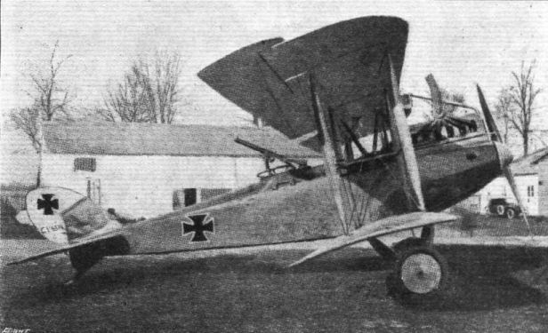
A recent type of German L.V.G. biplane of the C.V class.
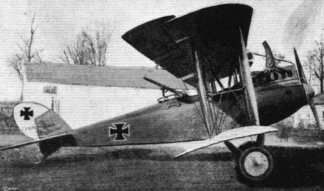
Side view of the L.V.G. C. V. biplane.
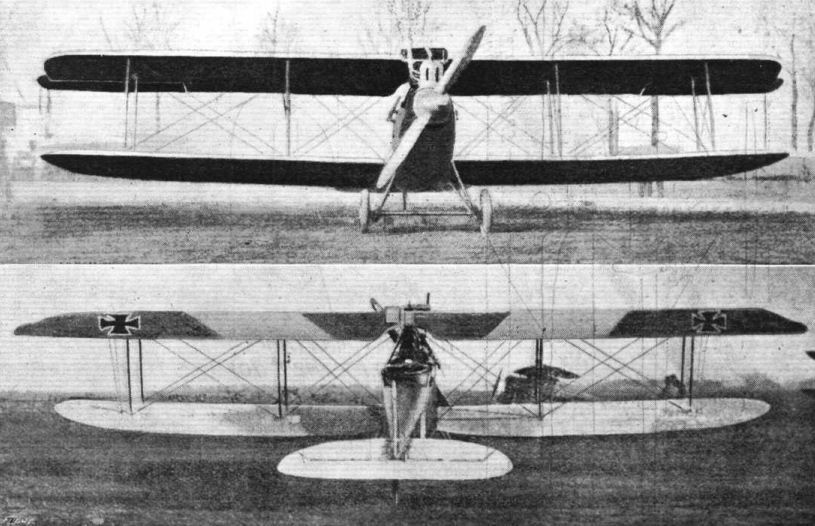
Front and rear views of the L.V.G. C. V. biplane.
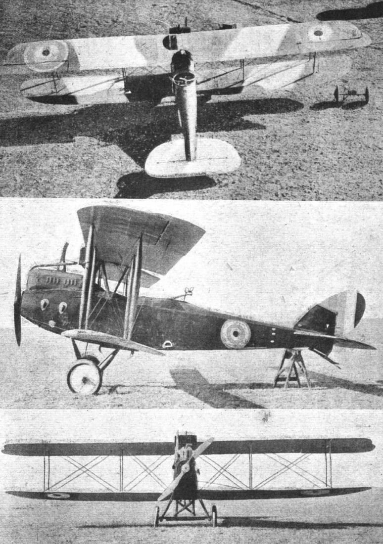
Three views of the Type C. V. L.V.G. Biplane.
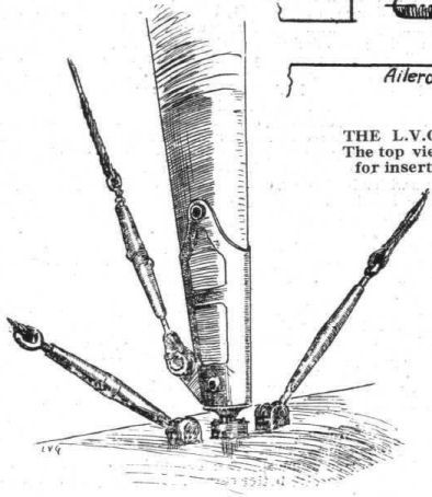
THE L.V.G. C.V. BIPLANE. - Sketch of one of the interplane strut fittings.
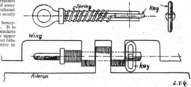
THE L.V.G. C.V. BIPLANE. - The locking hinge-pin for the aileron. The top view shows the pin removed, with the locking key in position for insertion. Below, the pin in position with the key "locked."
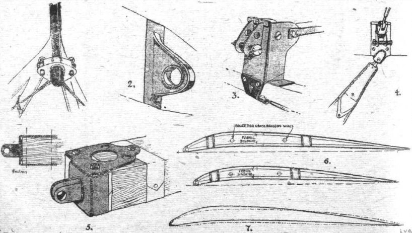
Some L.V.G. Constructional Details. - 1. Spar fitting on cabane of the Type C.V. L.V.G.; 2. Lug on spar engaging with fitting in 1; 3. Bottom front spar Joint; 4. Bottom rear spar joint; 5. Wing spar lug on the C.VI. Type; 6. Upper and lower wing sections of C.VI.; 7. C.VI. upper section with RAF. 14 section superimposed.
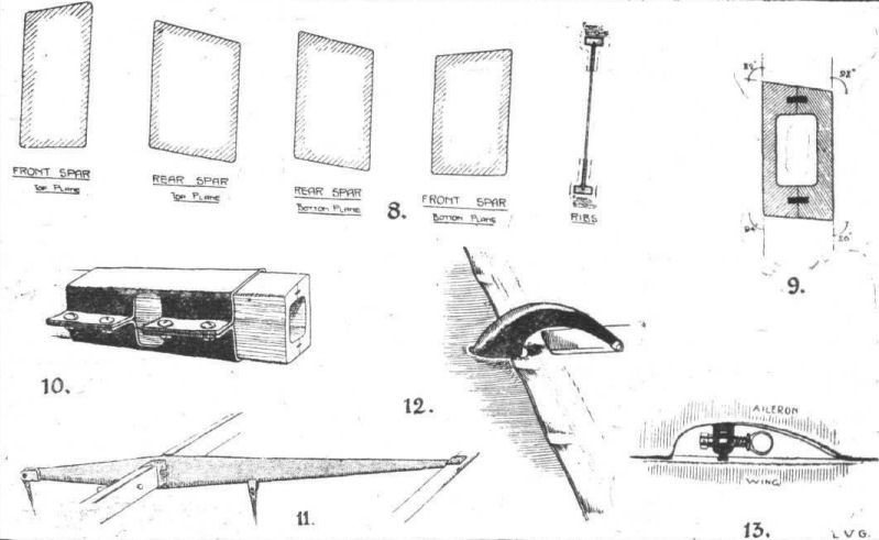
L.V.G. Constructional Details. - 8. C.VI. wing spar sections; 9. Front spar section of C.V.; 10. Field repair of broken spar; 11. Aileron crank of C.VI.; 12, Aileron crank of C.V.; 13. Aileron hinge of both types.
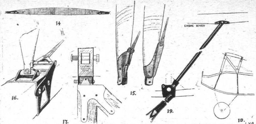
L.V.G. Constructional Details. - 14. C.V. inter-plane strut; 15. C.VI. inter-plane strut socket; 16. Attachment of strut to spar; 17. Attachment of centre section strut to spar on C.VI.; 18. Centre section struts and bulkheads of C.VI.; 19. Bracing tube between rear chassis strut and engine bearer on C.V.
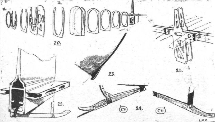
L.V.G. Constructional Details. - 20. The bulkheads of the C.V. fuselage; 21. Mounting of the tail plane; 22. Stern of fuselage, showing plywood covering and mounting of tail skids; 23. Protection piece for balanced portion of elevator; 24. Tail skids of the two types.
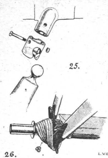
25 and 26. Undercarriage_details.
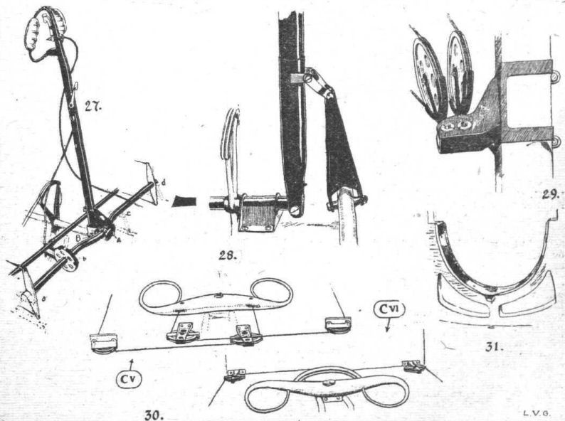
L.V.G. Constructional Details. - 27. Controls of C.V.; 28. Details of C.VI. controls; 29. Aileron pulleys; 30. Rudder bars of the two types; 31. Aluminium strip protectors of bulkheads against oil.
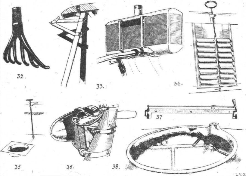
L.V.G. Constructional Details. - 32. Exhaust pipes of C.VI.; 33. C.V. Radiator supports and radiator; 34, C.VI. radiator shutter; 35. Camera hole and cover of C.V.; 36. Wireless generator mounted on chassis strut of C.VI.; 37. Release gear for unknown object on C.V.; 38. Gun ring of C.VI.
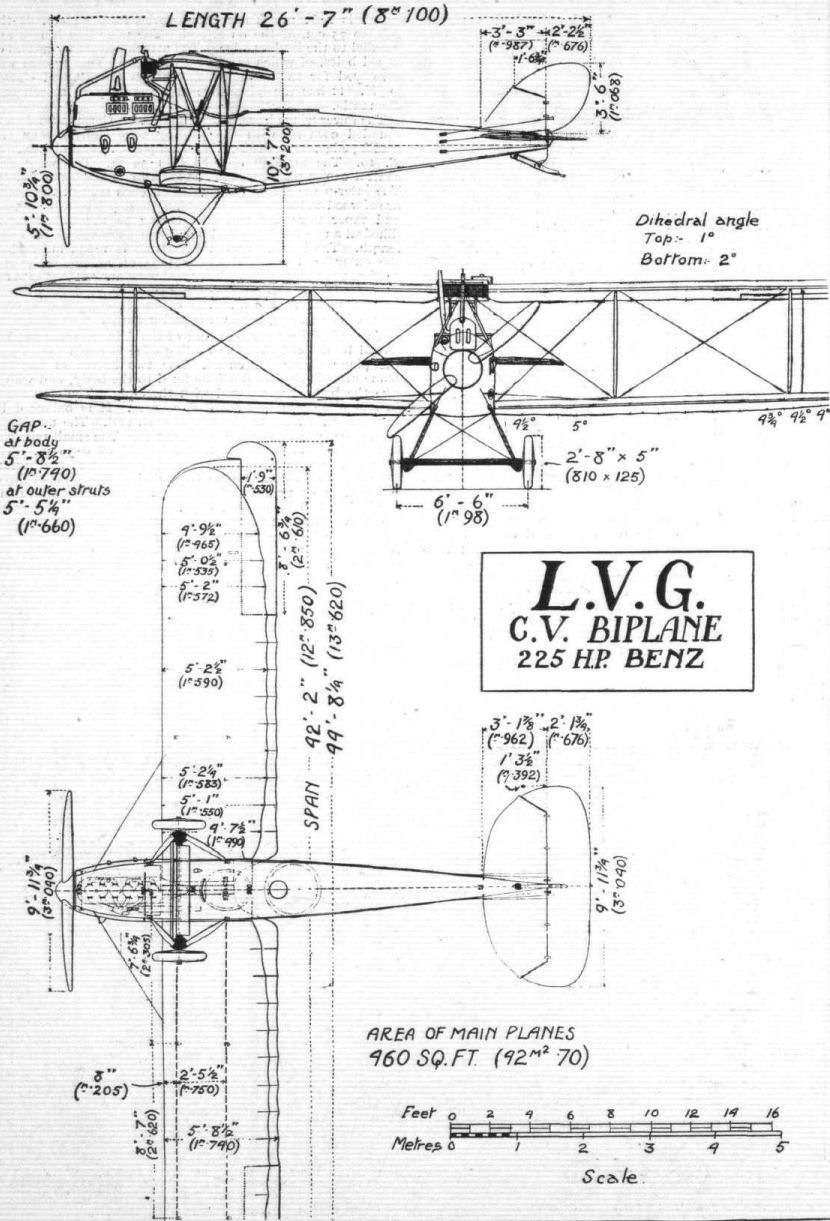
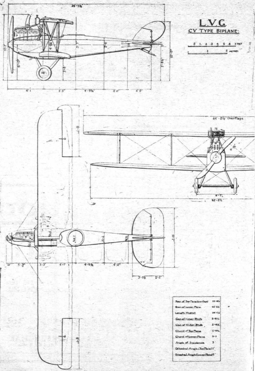
Flight, December 19, 1918.
THE L.V.G. TWO-SEATER BIPLANES
[Issued by Technical Department (Aircraft Production), Ministry of Munitions]
THIS report is concerned with two L.V.G. biplanes, of which one is of the C.V. type, while the other, a C.VI. type machine, is of later design, embodying certain alterations and improvements. The C.V. machine is allotted G/3Bde/5, and the C.VI. which was brought down near Proven on August 2nd by two S.E. 5's, piloted by Lieuts. Gordon and Gould, is alloted G/2 Bde/21.
Any description which follows and is not definitely stated to apply to either model, must be read as appertaining to the C.VI type.
The C.V. machine was only slightly damaged, and has been put into flying order, but the C.VI. has suffered severely, and it must be stated that on this account the G.A. drawings are not guaranteed to be of absolute accuracy in every respect. The greatest care has, however, been taken in their preparation, and only features of rigging such as dihedral and stagger (besides the tail planes, which are in a very fragmentary condition) are at all doubtful. In matters of detail the drawings are accurate.
Some leading particulars of both machines are given below :-
C.V. Type. C.VI. Type.
Weight empty 2,188 lbs. 2,090 lbs.
Total weight 3,141 lbs. 3,036 lbs.
Area of upper wings
(with ailerons) 238.4 sq. ft. 196.0 sq. ft.
Area of lower wings 190.4 sq. ft. 160.0 sq. ft.
Total area of wings 428.8 sq. ft. 356.0 sq. ft.
Loading per sq. ft. of
wing surface 7.3 lbs. 8.5 lbs.
Area of aileron, each 13.6 sq.ft. 11.2 sq. ft.
Area of balance of
aileron 0.4 sq. ft. 0.0 sq. ft.
Area of tail plane 21.6 sq. ft. 28.0 sq. ft.
Area of fin 5.2 sq. ft. 5.2 sq. ft,
Area of rudder 6.8 sq. ft. 6.8 sq. ft.
Area of balance of
rudder 0.6 sq. ft. 0.6 sq, ft.
Area of elevators 20.8 sq. ft. 16.0 sq. ft.
Area of balance of
elevator (one) 1.2 sq. ft. 0.8 sq. ft.
Total weight per h.p. 13.7 lbs. 13.2 lbs.
Crew 2 - Pilot and observer.
Armament 1 Spandau and 1 Parabellum
gun.
Engine 230 h.p. Benz.
Petrol capacity 52 1/2 gals. 52 1/2 gals.
Wings.
There are several important differences between the arrangement of main planes of the two models, as will be seen by referring to the G.A. drawings.
The wings of the C.V. L.V.G. are without stagger, and are not swept back, but both upper and lower planes are set at a dihedral angle, this being 1° for the upper, and 2° for the lower wings. The lower planes are smaller all round than the upper, and have rounded tips. The upper planes only have ailerons, which are of equal chord throughout their length, and are balanced. These planes also follow what was, until recently, the usual enemy practice, by being joined at their roots to a central cabane. There is, therefore, no horizontal centre section in this aeroplane, except for the 3-ply box (about 4 in, wide), which surrounds the horizontal tube of the cabane. For improving the view, the upper plane is cut away over the pilot's cockpit. Relative to the crankshaft the upper wing has a constant angle of incidence of 5°. That of the lower wing is the same, except at the tip, where the angle is washed out to 4°, and at the root to 4 1/2°.
Both upper and lower wings are attached to the body by the same general means, this being adapted to the particular positions and conditions of each joint. In the case of the upper planes, the cabane has lugs welded to its upper side at both ends. Fig. 1 shows the fitting at the forward end, and the pierced lug on the wing spar (see Fig. 2) fits into the fork. The same type of hinge pin is used for all wing joints, and for the aileron hinges also. It consists of a short length of steel tube, carrying at one end some form of stop, and at its other end a slot in which a short rectangular piece of steel is free to rotate, the steel piece being pivoted at its centre. Thus, when the steel piece is placed parallel to the tube, the whole fitting can be passed through any hole which will accommodate the tube, but when the piece is placed at right angles to the tube axis, the tube cannot be withdrawn through a small hole. A helical spring ensures that the steel piece shall be pressed against the hole, and not be free to slip into the parallel position.
The lower wing attachments are very similar, as will be gathered from Figs. 3 and 4, which show respectively the front and rear joints, and this plan has not been changed on the C.VI. type of L.V.G., except that the lug on the wing spar is now fashioned as shown in Fig. 5.
In the later model - the C.VI - the planes are of the same general shape, but important changes are remarked. The radiator has been moved from the position it occupied on the C.V. (see G.A. drawings), and is now built into the horizontal centre section. It is, of course, common German practice to build the radiator into the upper plane, and such a position is not incompatible with the cabane type of centre section strutting. This is particularly true when-as is the case in the. L.V.G.-a service petrol tank is supported by the upper plane, and can be made to balance the radiator. It is clear, therefore, that the alteration in design from the cabane system to the centre section system has not been made solely to accommodate the radiator.
So far as may be judged from the machine in its present condition, the C.VI has a positive stagger of 10 in., and both upper and lower planes have a similar dihedral angle, viz., 1°. Ailerons are still fitted to the upper plane only, but are not balanced in this model. The upper and lower wing sections of the C.VI. model are shown in Fig. 6, and Fig. 7 gives the C.VI. upper wing section with the R.A.F. 14 section superimposed. The R.A.F. 14 section is dotted.
(To be concluded.)
Flight, December 19, 1918.
THE L.V,G. TWO-SEATER BIPLANES
[Issued by Technical Department (Aircraft Production), Ministry of Munitions.]
(Concluded from page 1431.)
Wing Construction
(THESE details were all noticed in the C.VI. machine, as in the earlier type the planes are still covered with fabric.)
Both front and rear spars are of the box type, and wrapped with fabric. Sections drawn to scale are given in Fig. 8, but these drawings do not show internal construction, as the spars have not yet been divided.
The overall height and width of each spar, taken respectively parallel and perpendicular to the vertical walls, are :- Upper plane, front spar, height 3 1/4 in., width 1 7/16 in.; rear spar, height 3 in., width 1 15/16 in.; lower plane, rear spar, height 3 in., width 1 11/16 in.; front spar, height 2 7/8 in., width 1 11/16 in.
It has been possible to draw a section of the front spar of the C.V. machine, and the result is given in Fig. 9. There is every reason to believe that all the other spars of the L.V.G. are of similar construction. Fig. 10 shows a crude but effective method of repairing a broken spar. The repair was carried out by the enemy, probably in the field.
The leading edge is of the customary C section, and is followed at 7 in. interval by the front spar. The space between the two spars - 25 3/4 in. wide - is braced with cables and piano wire, and contains four ash compression struts of I section, which are simply butted into sockets obviously intended to carry steel tubes. (These compression struts are steel in the C.V. model.) The distance from the rear spar to the wire trailing edge is 2 ft. 6 3/8 in. The ribs, of which a section is shown, are of the usual type, and are spaced at intervals of 16 3/4 in., centre to centre. They are unlightened. Equally between them are placed two false ribs - mere strips of wood let into the leading edge and tacked to the spars. These false ribs have floating ends 7 1/2 in. behind the rear spar.
The construction of the lower plane does not differ from that of the upper plane just described, except that the false ribs are not found in it.
Ailerons
The ailerons of the L.V.G. no longer possess the peculiar step in the trailing edge that has for so long been associated with the design, and the ailerons are rather different in the two types. The C.V. model has ailerons which are balanced while those of the C.VI. are not. The respective areas are given on the first page of the report. With regard to the constructional features, only those of the later type can be described. The whole construction is of wood, with the exception of the aileron lever, a sketch of which is given (Fig. 11). This is of the usual curved type in the C.V. machine (see Fig. 12), but is made to serve as a rib also in the C.VI. type. The wooden ribs, together with the wood leading and trailing edges, form a structure which is very light. Both machines have the ailerons hinged to a false spar some distance behind the rear spar, and the hinges are all of the type that has already been described in connection with the wing attachments (see Fig. 13).
Struts
The L.V.G. is one of the few enemy aeroplanes that employ interplane struts of wood. They are of the shape shown in, Fig. 14, and are of streamline section (2 1/4 in. x 1 9/16 in.), slightly hollowed out for lightening purposes. Fabric is wrapped round the strut in three places, and the form of the strut sockets is made clear in the sketch (Fig. 14), which shows one of the C.V. struts.
The types of strut socket employed in the C.VI. machine is shown in Fig. 15, while Fig. 16 shows how the strut is attached to the spar. The socket is held in place on the strut by simply inserting a suitable length of steel tube through a drilled hole in socket and strut and riveting over the ends.
As has already been mentioned, the centre section struts are different in the two types. In the C.V. machine the cabane, the shape of which is made clear by the G.A. drawings, is made of streamline steel tubing. This has been changed, and the C.VI. model has parallel centre section struts of wood, which are like the letter N when seen from the port side. Fig. 17 shows the pint between the spar of the centre section and the strut. The unusual arrangement of the cross-bracing of this centre section should be noticed in the front view, G.A. drawings.
The line of the front limb of the N is carried on by the third fuselage bulkhead, and finishes at the front joint of fuselage and undercarriage. The angle between the rear two limbs of the N is practically bisected by the line of the fifth bulkhead, which finishes at the rear joint of fuselage and undercarriage. This is shown by a diagram, Fig. 18. The C.V. machine has a sloping steel tubular strut between engine bearer and rear undercarriage attachment (see Fig. 19), but by the rearrangement of bulkheads the necessity for this has vanished, and the strut is not found in the later model.
Fuselage
The earlier types of L.V.G. had bodies built on the cross-braced girder system. Both the machines described possess the same type of fuselage, totally different from the girder system, viz., a framework of bulkheads and longerons, covered with a thin layer of 3-ply and totally without wire bracing. Fig. 20 gives the number of shapes of the bulkhead in the C.V. machine, and incidentally reveals the shape of the fuselage. The C.VI. type has generally the same arrangement, but the third and fifth, bulkhead are no longer vertical in this model, and the tail part of the body has been strengthened by the insertion of another cross piece.
Although the fuselage of the L.V.G. biplane ends in a vertical wedge, the provision of a centre section for the tail plane gives a cruciform appearance to this part. This is shown clearly by Fig. 21, where the two sides of the tail plane centre section are drawn in thin lines. The 3-ply covering to the fuselage rounds off the joint of body and tail plane in the neat way that is found in so many German aeroplanes. (See Fig. 22.)
Tail
The shape of the fixed tail planes is shown in the G.A. drawings. The main box spar (see dotted section in Fig. 21) passes right through the body. The rear spar, to which the elevators are hinged, is of rectangular section wood, hollowed on its rear face to take the steel tube which serves as the elevator spar. The tail is so badly damaged that detailed analysis is impossible, but the fixed tail planes are of wooden construction, with the usual ribs and semicircular leading edge. It will be noticed that the tail plane is not set parallel to the crankshaft line, but is raised through an angle of 5°, and it has a symmetrical streamline section.
The elevator, which is balanced and undivided in both models, is a welded structure of light steel tubing, and presents no unusual feature. There is a small protecting horn provided on the tail plane, to prevent damage to the corner of the balanced portion of the elevator - Fig. 23 gives a clear idea of this example of thoroughness.
The tail skids are both of the same general type as that of the Pfalz Scout, i.e., the member is entirely exposed, and does not project into the fuselage. It is of ash, and the upper end is so shaped as to avoid the necessity for any metal link or fitting. Both machines also have a small triangular fin on the underside of the fuselage which serves the double purpose of providing fin area and of adapting the shape of the fuselage to the slope required for the tail skid. (See Fig. 22.)
It will be seen from the sketch (Fig. 24) that the skid of the C.V. machine carries a four-leaved fiat spring bolted a little to the rear of the pivot. In the later model this has been discarded. The shape of the lower triangular fin also differs slightly - that of the C.VI. has been simplified and strengthened. The workmanship of the sheet steel angle piece on the C.VI. machine gives one the impression that it is a "squadron fitting." It is of fairly heavy gauge, and may have replaced a weaker part fitted by the manufacturer.
Undercarriage
The landing gears of both machines are similar, and in general arrangement conform to the practice that is now practically standard. The vee struts are of streamline section, and constructed of fabric-covered wood. The practice of using wood for undercarriage struts is, of course, unusual in enemy machines, but is in conformity with the other struts - interplane and centre section - on this machine.
The major and minor axes of cross section of one of the front struts (and all four, front and rear, are of equal dimensions) are respectively 2 9/32 in. and 4 7/8 in.
The upper and lower extremities are capped with steel sockets, which allow of attachment to the fuselage at the upper extremities and at the lower ends serve to connect the two limbs of the vee, and are provided with accommodation for the shock absorber. Figs. 25 and 26 show respectively the component parts of the attachment to the fuselage, and the socket at the lower part of the vee. From Fig. 25 it will be noticed that the ball at the head of the strut beds into a hemispherical socket attached to the fuselage. The lower half of the ball articulates with a curved surface on the ferrule, and the ferrule next slipped over attachment. In assembling this joint - and this is a matter of seconds only - the ball is first passed through the opening provided on the ferrule, and the ferrule next slipped over the body lug and pinned in place. All four body attachments are of this type in the C.VI, machines, but in the C.V. model the joint was made by simply pinning the ball to its socket, without the refinement of a ferrule.
The shock absorber is of the coil spring type, with three small diameter springs lying side by side, as indicated in Fig. 26. A loop of cable limits the amount of axle travel, and between the lower extremities of the vees is a steel compression tube, of 1 1/2 in. O.D., and behind this lies the axle, which is encased in a 3-ply fairing. It will be noticed that the compression tube is not included in the fairing, and when the axle is raised as the machine lands, the fairing travels with the axle. This method allows of good accessibility to these components, but is not quite so good an arrangement from the streamline point of view as the common method of allowing the axle to lift out of a fixed fairing.
The schedule of principal weights, given at the end of this report, is of considerable interest as regards the undercarriage.
The wheels are 810 x 125, and the track 6 ft. 7 in. The cross bracing does not start from either front or rear fuselage attachments, but from the front spar joint on the fuselage.
Controls
As is the case throughout the design, the controls of the two aeroplanes are generally similar, but differ in detail. In the C.V. machine, the control lever, at the head of which is the usual two-handed grip, operates two rocking shafts which axe perpendicular to one another. The transverse tube, which actuates the elevators, is cranked in the middle and supported on four brackets, marked a, b, c, and d, in Fig. 27, which act as bearings. To the middle point is pinned the front half of the jaw which is found on the bottom of the control lever. This pin A, always points directly to the centre of the pin B, which passes through the rear half of the jaw and is itself always exactly in line with the bearing of the transverse shaft. This somewhat complicated arrangement allows the transverse shaft to be rotated round axis a, b, B, c, d, and at the same time permits the other shaft to rock on its own bearings. A simple contracting band brake controlled by a Bowden lever and cable serves to lock the elevator controls in any desired position. This brake is found in both types.
The C.VI. controls are rather different, and are shown in Fig. 28, which clearly explains their operation. The naked aileron control cables pass through the lower wing near the rear spar, and run over the aluminium pulleys illustrated in Fig. 29. The upper extremities of these cables are attached to the welded control lever which works in a slot in the upper plane. The differences between the two types in the matter of the aileron lever has already been commented upon.
The rudder bars of the two types are of the same general design, but the problem of leading the cables round the base of the large petrol tank immediately behind the rudder bar, is solved in different ways. In the later type, a semicircular extension to the rudder bar avoids the necessity for the two extra pulleys and bearings found in the C.V. type. Reference to Fig. 30 will make this point clear.
Engine Mounting and Control
The 230 h.p. Benz engine is mounted on wooden bearers of rectangular section, 1 5/8 in. wide and 3 1/4 in. deep, supported on the cross bulkheads found in the front of the fuselage. In the C.V. machine there is a steel tubular strut on each side which is in compression between the rear portion of the engine bearer and the front undercarriage joint (see Fig. 19). As has already been mentioned, the rearrangement of the fuselage bulkheads allows this strut to be dispensed with in the C.VI. model.
The throttle lever is of the familiar ratchet-quadrant type, and in the C.V. machine there is no interconnected throttle lever on the control stick. Although the C.VI. control lever is missing, it is fairly certain that this is true of this type also. Those bulkheads which are likely to receive oil drippings from the crankcase are protected by aluminium strips employed in the manner shown in Fig. 31.
Oil and Petrol Systems
Both machines have a main petrol tank under the pilot's seat and a gravity tank attached to the upper plane. In the C.V. machine this tank is placed on the upper surface of the port plane, alongside the narrow centre section. The later type has the tank beneath the port upper plane, as will he noticed from the scale drawings. In this case the filler passes through the plane, and has the cap on the plane's.
The C.VI. main tank has a capacity of 47 gallons, and the gravity tank a capacity of 5 1/2 gallons, thus giving a total petrol capacity of 52 1/2 gallons. There is a hand petrol pump which allows the pilot to fill the gravity tank from the main tank, and an engine petrol pump which draws fuel from the main tank and passes it on under pressure to the small cylindrical compartment of the main tank, whence it flows to the carburettor. This is, of course, the usual Benz system, and has been fully reported upon.
The exhaust pipes are of welded sheet steel, and are carried higher than is usual in the C.VI. model (see Fig. 32).
Radiator
The positions respectively occupied by the radiators of the two models are quite different; though both are in conformity with enemy practice. Reference to the scale drawings will make it clear that the C.V radiator is supported in front of the leading edge of the upper plane on struts clamped to the cabane, while that of the C.VI. occupies the middle part of the centre section and is flush with the curvature. The construction also differs. The vertical (C.V.) radiator is composed of flat vertical films, which are crimped and set "staggered" so that their appearance is similar to that of a honeycomb radiator. The C.V. type has the usual oval section brass tubes running perpendicular to the chord of the wing. Fig. 33 gives a sketch of the earlier radiator, and of its supports. The shutters work on different systems, as will be noticed from the sketches. The vertical shutter of the C.V. machine is of the roller blind type, with cables which operate positively, one to unroll and the other to roll up the blind. This shutter puts out of action approximately one-third of the radiator area. The C.VI. shutter effect is obtained by moving a handle which alters the slope of nine parallel hinged flaps, as illustrated in Fig. 34.
Instruments
The pilot's cockpit is not provided with a dashboard, but the instruments are distributed chiefly on the left-hand side of the pilot. They comprise the usual Bosch starting magneto and key switch; an oil-pressure gauge calibrated to 4 kg. per sq. cm.; a petrol-pressure gauge to 5 kg. per sq. cm.; a Maximall petrol gauge to the main tank, a grease pump, and throttle and ignition levers of the usual type.
The observer's cockpits of both machines are provided with circular camera holes in the flooring, and each hole is fitted with an aluminium cover, but these covers are manipulated differently. The aperture of the C.V. machine is about 9 in. in diameter, and the type of cover is clearly shown in Fig. 35. That of the C.VI. model is 12 in. in diameter, and is covered simply by an aluminium sheet which slides in parallel grooves outside the fuselage. The C.VI. biplane was fitted with a complete wireless outfit when captured, but of the internal fittings only the aerial and reel remain, and these m entirely standard. The current was obtained from a dynamo attached to the undercarriage strut, which is still in situ, though its propeller is missing. This dynamo is shown in Fig. 36.
The fitting shown in Fig. 37 was found on the starboard side of the C.V. machine; and is obviously a release for some light object. Its precise function is unknown. Fig. 38 shows the C.VI. gun ring, and it will be noticed that the padded clip is not in its usual vertical position.
Fabric and Dope
The usual printed fabric with a design of coloured polygons is used - and nothing regarding fabric or painting calls for comment
Schedule of Principal Weights (C.VI. Type)
lbs. ozs.
Fuselage, without undercarriage, engine, or centre
section 440 0
Lower wing, covered complete (no ailerons) 76 12
Upper wing, covered complete (with ailerons) 85 4
Centre section without struts or cable 64 0
Centre section N struts 5 8
Interplane strut, each 3 11
Aileron, covered, each 8 4
Balanced elevator, covered, complete in one piece 14 8
Undercarriage, comprising :-
2 Vees, bare 29 1
2 Wheels with tyres 55 8
2 axle caps, with pins 0 6
2 shock absorber bobbins 1 4
2 shock absorber 17 6
Axle and fairings 23 2 1/2
Compression tube in front of axle 3 0
2 bracing wires, with strainers 2 0
4 ferrules 0 10
Undercarriage, complete 132 5 1/2
Tail skid, bare 4 6
Brass oil tank with 20 ins. copper pipe 9 7
Ammunition magazine (aluminium) 5 0
Exhaust pipe 16 4
Spinner 2 9
Dynamo, without propeller 23 12
Both of these aeroplanes are at present at the Enemy Aircraft View Room, Islington. Passes may be obtained on application to :- The Controller, Technical Department, Ap.D. (L.), Central House, Kingsway, W.C. 2.
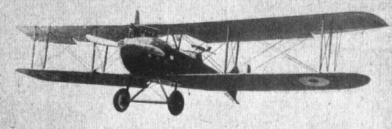
Views of the Type C. VI. L.V.G. Biplane.
Some L.V.G. Constructional Details. - 1. Spar fitting on cabane of the Type C.V. L.V.G.; 2. Lug on spar engaging with fitting in 1; 3. Bottom front spar Joint; 4. Bottom rear spar joint; 5. Wing spar lug on the C.VI. Type; 6. Upper and lower wing sections of C.VI.; 7. C.VI. upper section with RAF. 14 section superimposed.
L.V.G. Constructional Details. - 8. C.VI. wing spar sections; 9. Front spar section of C.V.; 10. Field repair of broken spar; 11. Aileron crank of C.VI.; 12, Aileron crank of C.V.; 13. Aileron hinge of both types.
L.V.G. Constructional Details. - 14. C.V. inter-plane strut; 15. C.VI. inter-plane strut socket; 16. Attachment of strut to spar; 17. Attachment of centre section strut to spar on C.VI.; 18. Centre section struts and bulkheads of C.VI.; 19. Bracing tube between rear chassis strut and engine bearer on C.V.
L.V.G. Constructional Details. - 20. The bulkheads of the C.V. fuselage; 21. Mounting of the tail plane; 22. Stern of fuselage, showing plywood covering and mounting of tail skids; 23. Protection piece for balanced portion of elevator; 24. Tail skids of the two types.
25 and 26. Undercarriage_details.
L.V.G. Constructional Details. - 27. Controls of C.V.; 28. Details of C.VI. controls; 29. Aileron pulleys; 30. Rudder bars of the two types; 31. Aluminium strip protectors of bulkheads against oil.
L.V.G. Constructional Details. - 32. Exhaust pipes of C.VI.; 33. C.V. Radiator supports and radiator; 34, C.VI. radiator shutter; 35. Camera hole and cover of C.V.; 36. Wireless generator mounted on chassis strut of C.VI.; 37. Release gear for unknown object on C.V.; 38. Gun ring of C.VI.

General Arrangement Drawings of the Type C. VI L.V.G. biplane.

Three views of a German Pfalz monoplane, from a recent German publication. This machine is, so far as one is able to ascertain, an exact copy of the pre-war French Morane. The machine has not, we believe, been built for several years.
Flight, April 18, 1918.
THE PFALZ SINGLE-SEATER FIGHTER.
AMONG the more recent German single-seater fighters there is one which up to the present has been little known to the general public, although it is, as far as we have been able to ascertain, employed to a considerable extent by the enemy and by no means unknown to our pilots at the front. We are referring to the Pfalz scout, of which we are able to publish this week, by the courtesy of the authorities, three photographs and a few brief particulars. Several of these machines have fallen into our hands, and later on we hope to refer to this interesting machine in more detail than is possible this week. The preparation of the necessary drawings and sketches takes a considerable time, but so as to lose no time in placing before our readers illustrations which may be helpful for purposes of identification we are referring to it briefly in this issue.
In outward appearance the Pfalz scout is chiefly remarkable on account of the fact that it imitates, as do the recent Albatros scouts, the wing bracing originated by the Nieuport firm, incorporating a larger top plane and a smaller lower plane. The type is frequently termed by the Germans a one-and-a-half plane. The wing bracing differs, as regards the inter-plane struts, from that of the later type Albatros single-seaters in that the lower ends of the struts do not meet at a point, but are connected by a short horizontal member. The lower plane has two spars according to usual practice, although these are placed rather close together, thus forming in reality a compromise between the single-spar lower plane of small chord and the ordinary two-spar lower plane with chord equal to that of the top plane.
The Pfalz follows Albatros practice in that the upper wing runs right through, and is in one piece. This construction is possible on account of the fact that no dihedral angle is given to the wings. The top plane is mounted on struts sloping outward from the body.
The attachment of the lower wing to the body is interesting. Instead of the attachment usually found there is on the Pfalz scout a short wing root, built integrally with the body, to which the lower spars are secured. In order to attain this the three-ply covering of the body has a reflex curvature at this point, from the convex curve of the body to a concave curve gradually merging into the shape of the wing section. There can be little doubt that this has been done in order to minimise resistance, but whether or not it achieves this purpose to any considerable degree may perhaps be open to doubt.
The body of the Pfalz single-seater is of elliptical cross section and appears to be of comparatively good streamline form. It is deep so as to allow only just the top of the pilot's head to project outside, and to bring the top plane down low so as to obstruct the view to a lesser extent. It is narrow so as to allow the pilot a good view downward, the narrow overall width being rendered possible by the adoption of the semi-monocoque construction.
Although being in general principle similar to the Albatros construction the body of the Pfalz differs somewhat in the manner of applying the ply-wood covering. Whereas that of the Albatros is put on in short rectangular sections, each covering only one span between adjacent body formers, the covering of the Pfalz is in the form of two thicknesses of three-ply, each in the form of long narrow strips put on diagonally, the strips of the inner skin and those of the outer running at approximately right angles to one another. It would appear that this form of construction is of some advantage, inasmuch as difficulty is always experienced in getting three-ply wood to bend to a double curvature. A sheet of three-ply may be readily bent along one axis, but even a very thin sheet will protest if one tries to bend it in addition along an axis at right angles to the former. The fact is, therefore, almost certainly at the bottom of the Pfalz construction. However, this is a subject to which we hope to return later.
To the casual observer the tail planes of the Pfalz do not present anything of particular interest, but a closer examination reveals the fact that the tail plane appears to be put on "the wrong way round." That is to say, it has a flat top surface and a convex bottom surface. As far as is possible to judge from a somewhat hurried inspection, the tail plane is not set at any angle of incidence to the line of flight - either positive or negative - and one would therefore rather expect that during a steep dive the tail plane would exert a somewhat excessive righting force tending to "flatten out" the machine rather abruptly. This is so unusual in a German machine, where frequently the tail plane is set at a positive angle of lift, as to give food for some speculation.
The engine fitted to the Pfalz scout in question is a 160 h.p. Mercedes, which, as the accompanying photographs show, is neatly covered in with the exception of the extreme top of the cylinders. We have at the moment no figures regarding performance, but in view of the evident low resistance of the body the speed may safely be assumed to be fairly good.
Flight, July 25, 1918.
THE PFALZ SINGLE-SEATER FIGHTER.
160 H.P. MERCEDES ENGINE.
In our issue of April 18th, 1918, we published some photographs and a brief description of the Pfalz single-seater fighter. We have, since then, by the courtesy of the authorities, been permitted to examine in detail, and sketch, one of these machines exhibited at the Enemy Aircraft View Rooms. Owing to the fact that several of these machines have been captured, there is available a great number of parts, so that it has been possible to ascertain the internal construction of practically all the details, many of which are very interesting. As the Pfalz is, constructionally, rather different from the general run of German machines, we propose to devote a considerable space to it, hoping that the information thus conveyed will be found both useful and interesting to all concerned in the production and use of aircraft. - ED.]
As a type the Pfalz belongs to the single-seater fighter class with low-resistance body, which during the last twelve months or so has been given more attention in Germany than ever before. Up till that time German designers had, generally speaking, troubled little about cutting down head resistance on their machines, trusting, presumably, to their high-power water-cooled engines to pull them through. As, however, the machines of the Allies increased in speed and climb it became obvious that something more than mere engine power would be required to cope with the constantly increasing demands, and once this was realised several German firms began to look around for ways and means of improving the performance of their machines. Among these were the Albatros firm, which turned out some single-seater fighters, incorporating the Nieuport type wing bracing and the semi-monocoque body of stream-line shape. It was on machines of this type that the pilots of the "Richthofen Circus" did much of their fighting. Then there was the Roland fighter, in which attempts were also made at stream-lining the body, but which went rather farther and made the body so deep as to serve directly as a support for the top plane. Finally we have the Pfalz, in which stream-lining has been carried a little farther still, inasmuch as the attachment of the lower wings takes the form of wing roots formed integrally with the body and the object of which is presumably to avoid sharp corners at the juncture of wings and body. The wing arrangement of the Pfalz also differs slightly from that of the Albatros in that the inter-plane struts do not come to a point on a single lower spar, but are separate at their lower ends by a short horizontal piece, evidently so as to enable the struts to take care of the twisting moment due to the travel of the c.p. better than can be done with a point attachment.
An examination of the Pfalz biplane gives the impression, also conveyed in the accompanying drawings, of very low resistance indeed, and with an engine of 160 h.p. one naturally expects the machine to have an excellent speed. Tests carried out in this country do not, however, confirm this first impression, and the following particulars of performance can only be regarded as disappointing in view of the promising appearance of the Pfalz, and this is another proof of the difficulty of judging "by eye" the merits or otherwise of a machine.
According to the official report on the tests the following data were established :-
Pfalz Scout, No. G. 141.
Engine 160 h.p. Mercedes.
Number of crew One.
Military duty Fighter.
Propeller Axial, Berlin.
Total military load 281 lbs.
Climb to 10,000 ft. In 17 mins. 30 secs.
Speed at 10,000 ft. 102 1/2 m.p.h.; revs., 1,400 r.p.m.
Rate of climb 360 ft./min.; revs., 1,310 r.p.m.
Climb to 15,000 ft. In 41 mins. 20 secs.
Speed at 15,000 ft. 91 1/2 m.p.h.; revs., 1,325 r.p.m.
Rate of climb 100 ft./min.; revs., 1,280 r.p.m.
Estimated absolute ceiling 17,000 ft.
Greatest height reached 15,000 ft. in 41 mins. 20 secs.
The total military load is made up as follows :-
Riot 180 lbs.
Two Spandau guns 70 "
Dead weight 31 "
Total 281 "
Weight per sq. ft. 8.56 lbs.
Weight per h.p. 12.84 "
Total weight of machine, fully loaded 2,056 lbs.
Weight of machine, bare, with water 1,580 lbs.
Military load, less crew 101 "
Crew, as above 180 "
Petrol, 21 1/2 galls 155 "
Oil, 4 galls. 40 "
Total 2056 "
The first question that naturally comes to mind after studying this table of performances is. What is the reason for this poor performance, for it can scarcely be termed otherwise. Some of the figures given in the table may help to furnish the solution, although after perusing them there are still several remaining unanswered. For instance, the wing loading is somewhat high, but certainly not so much so as to account by itself for the low maximum speed and low rate of climb. The body appears to be of good streamline form, but against this must be placed the fact that the maximum cross sectional area is comparatively large, owing to the deep body reaching nearly to the top plane. As regards the wing bracing, this is simple enough as far as concerns the number of wires and struts, but the cables are not faired, and as they are of rather large diameter, their resistance at maximum speed may reasonably be assumed to be fairly high. If, however, the detrimental resistance is considerable, the wing resistance is probably no less so, the wing section being of the deeply cambered type so favoured by German designers, and which has, generally speaking, a somewhat high drag, although its lift is good. We have for some time held the opinion that German designers were deliberately employing deeply cambered sections with a view to obtaining better performance at altitudes, but we are bound to admit that the official tests of the Pfalz scarcely appear to bear out this contention. We would strongly urge that the authorities have tests carried out at the N.P.L. on all the German wing sections of which data are available, as the publications of the results of such tests would be of the greatest interest. We do not for a moment imagine that the sections would reveal any superiority over those more commonly employed by the Allies, but some interesting facts might nevertheless be brought to light, which might be of use to our own designers, if only as a warning regarding what not to do.
Constructionally the Pfalz single-seater is even more interesting, showing, as it does, considerable departures in detail design from other German makes of the same class, on which its fundamental arrangement is evidently founded. This refers especially to the Albatros fighter single-seater, which is characterised by the same main features, such as large top plane and small bottom plane, one pair of interplane Vee struts on each side, ply-wood streamline body, &c. Apart from minor differences in shape, the Pfalz designer has chiefly struck out along original lines in the construction of the body. Whereas in the Albatros one finds the same oval formers connected by longitudinal rails, the manner of applying the three-ply covering is totally different in the two machines. In the Albatros the ply-wood is put on in small pieces covering only a bay or so; the covering of the Pfalz is in the form of long strips spirally laid on, the strips of the two layers forming an angle with one another.
In Fig. 1 is shown the general arrangement of the Pfalz body. There are in all eight longerons, it will be noticed-one at the top, one at the bottom, one half-way up on each side and four at what would be the corners in a rectangular section body. These longerons run the whole length of the body, with the exception of the top one, which is terminated just to the rear of the engine, and are attached to the formers as shown in the sketch, Fig. 2. The longerons are stop-chambered so as to leave them solid where occur the formers, into which they are sunk and secured by a wood screw. The formers themselves are built up of smaller pieces of spruce, lap-jointed and covered each side with a facing of three-ply wood.
Reference has already been made to the fact that wing roots are formed integrally with the body. These roots can be seen in the side view, Fig. 1; and account for the peculiar shape of formers III and IV. Judging by these formers the cross-sectional area is unduly increased at this point, although this may be partly made up for by the shape of the-ply-wood covering, which merges the lines of the lower plane into the curves of the body. This is illustrated in the two sketches, Fig. 3. It is, perhaps, open to doubt whether or not this elaborate arrangement is worth while. Constructionally it must necessarily entail considerable extra work, and aerodynamically it does not look as neat and efficient as the Albatros way of doing the same thing by frankly letting the bottom plane abut directly on the curved sides of the body.
Fig. 4 is a perspective view of the Pfalz body, and serves in conjunction with Fig. 1 to explain the general arrangement of formers and longerons. Some of the formers, it will be noticed, are sloped in relation to the others. Thus, for instance, the former in the neighbourhood of the pilot's seat slopes back so as to bring it approximately into line with the rear chassis struts, while rigidity is lent to the front portion of the body by sloping one of the formers carrying the engine bearers until its top meets the top of the next former. In this point also the formers are joined to the front struts carrying the top plane, while one of them serves, at the point of attachment of the bottom corner longeron, to transmit the load from the front chassis struts.
One of the difficulties of monocoque body construction has always been that you cannot bend three-ply sheet over a double curvature. That is to say, in sheet form the three-ply will bend willingly to the curvature of the converging sides of a flat-sided body; but as soon as the sides are no longer flat but have a curvature, however slight, three-ply in sheet form cannot be employed. In the Albatros this difficulty is overcome by using small sheets, covering only one bay, and forming in reality, although it is not noticeable, a series of straight bays. In the Pfalz a different method has been employed. The body covering consists of two layers of three-ply, each less than 1 mm. thick. The plywood is evidently manufactured in sheets, and before applying to the body is cut up into parallel strips of about 3 to 4 ins. the width apparently varying considerably throughout the body. The first layer of three-ply is then put on by bending it diagonally around the body, attaching it by tacking to the various longerons, en route, and cutting each narrow strip at the top and bottom longerons, which form the terminals so to speak of the three-ply covering, which is thus applied in two halves. The second layer of strips is then laid on top of the first, but at a different angle, to which it is secured by glueing, and finally tacked to the longerons. The inside layer is reinforced, in the front portion of the body, by glueing tapes over the joint between adjoining strips of plywood. This and other details are shown in Fig. 5. In order to spread a joint in the ply-wood over as large an area as possible the joint is made, as shown, in a sort of saw tooth or serrated butt joint style. This, in brief, is the fundamental construction of the Pfalz body, and differs considerably from other makes. As to its efficiency - we cannot speak. The weight at any rate, judging from the comparatively low total weight of the machine, can scarcely be any greater than the girder type of body, but as regards strength we have no information. We have heard it said that the Pfalz machines have a habit of breaking their bodies just aft of the pilot's cockpit, but for the accuracy of this statement we cannot vouch. As a compromise between sheet three-ply covering and true monococque construction the Pfalz method would appear to have certain advantages.
(To be continued.)
Flight, August 1, 1918.
THE PFALZ SINGLE-SEATER FIGHTER.
160 H.P. MERCEDES ENGINE.
(Continued from page 827.)
AT the stern the Pfalz body terminates, as shown in the illustrations in our last issue and further illustrated in detail in Fig. 6, in a somewhat elaborate framework of wood, which performs the various functions of forming supports for the tail plane, tail skid, and vertical fin with its rudder. The design of this part of the body must have provided some pretty problems in projection drawing, and one is inclined to think that a little less rigid economy in metal fittings might have resulted in a considerably simpler design. The second former from the stern is, it will be seen from Fig. 6, sloped backwards to form the leading edge of the vertical fin, and is reinforced above the body with other pieces of' wood to give it a rounded edge. The last former is in duplicate, its front half extending upwards to form a member of the fin, while the other half terminates just above the body and serves chiefly as a support for the short length of spar to which the front spar of the tail plane is attached. Between these two formers and sloping so as to form in side view a cross, are another two formers, built up in much the same manner as the main body formers. The angle formed by one of these and the longeron accommodates the leading edge of the small plane permanently fixed to the body, while the point of intersection of the two formers supports a short transverse cylindrical piece of wood, around which is wrapped the shock absorbers for the tail skid. The details of both these joints are shown in the sketches of Fig. 6. The small tail plane root is covered, on the actual machine, with plywood, but this has been omitted in the sketch in order to better show the constructional details.
The tail plane itself is in one piece, and fits into the slot provided for it in the body. The manner in which it is secured after being placed in its slot will be clear from an inspection of Fig. 7. The front spar rests in the slot in the body, and is secured against lateral tilting by a steel band on each side, overlapping the butt joint between the front part of the rib and the tail plane root, as shown in Fig. 7. The rear spar of the tail plane is locked in place by two long bolts and a stud. The two bolts are placed one on each side of the stern, as indicated in the sketch in Fig. 7, while the stud passes through a lug welded on to the extreme rear of the steel shoe surrounding the heel of the fuselage into another lug near the foot of the stern post. The whole tail plane with its elevator can therefore be removed by undoing five nuts, and, of course, the connections in the elevator control cables.
As regards the tail plane and elevator themselves, these are constructed along more or less standard lines and do not present any especially remarkable features. It has already been pointed out that the tail plane appears at first sight to have been put on "upside down," having a flat top surface and a convex bottom surface. The reason for this is not apparent, but it is possible that the disposition of the various weights and surfaces is such that there is either a lift-weight couple or a thrust resistance couple or both; and that this section tail plane has been employed to equalise such couples. However, in a later machine captured and now at the Enemy Aircraft View Rooms the shape of the tail plane had been altered to a symmetrical section, so that it would appear that the "inverted" section has either been found unsatisfactory in practice or the reasons for its employment removed in a later design. Structurally the tail plane is built up of spruce spars with ribs having ash flanges and poplar webs. The inner ribs an covered with three-ply to give extra rigidity for attachment to the body. The front spar is of I section while the rear spar is channel section, with recesses top and bottom for forming a flat surface with the rib flanges. There is no internal wire bracing, the necessary rigidity being obtained by means of diagonal ribs and by plates of three-ply placed over the joints between-ribs and spars. The leading edge, which is also bent back to form the tips of the tail plane, is laminated as shown in Fig. 7, and is lightened by spindling between the ribs. The laminations are probably steamed so as to be easily bent to form the rounded corners of the tail plane.
The elevator, owing to the fact that the rudder has no downward projection, is in one piece, and is built up in a manner similar to that of the tail plane. Its leading edge is formed by a box spar, and the ribs are similar to those of the tail plane. The attachment of the ribs to the trailing edge is somewhat unusual. Instead of the flanges of the ribs passing over the trailing edge they are thinned down and pass into a slot in the trailing edge as shown inset in Fig. 7. They are then secured in place by a small metal clip. The slots in the trailing edge appear to have been made with a circular cutter of about 3 in. diameter, the ends of the rib flanges being placed where the slot is deepest. The elevator hinges are formed by forked bolts passing through the rear spar of the tail plane, and corresponding with eye bolts through the leading edge of the elevator.
The elevator crank levers are of a type frequently found on German machines. The crank itself is of streamline section, and is welded to a channel section base plate surrounding three sides of the leading edge. Another base plate of similar shape, but made of lighter gauge, is slipped over the leading edge from the front, and forms a washer for the hinge bolt, which passes through the leading edge at a point coincident with the crank lever. The attachment of the elevator and rudder cables to their respective cranks is in the form of a ball and socket, joint, or, more correctly speaking, the ball portion of it is not a complete ball but a slice of a sphere, formed integrally with the bolt passing out of the socket into the barrel of the wire-strainer. The socket, and also the ball have a flat formed on one side so as to prevent the ball from turning in the socket. Behind the ball a small split-pin passes transversely through the socket, thus preventing the ball from dropping out of the socket when the control cables are removed. The socket is kept filled with grease.
The rudder, which, as already pointed out, is placed wholly above the elevator, is built entirely of steel tubing. The ribs are joined, not directly to the rudder post, but to a collar of very light gauge, which is in turn pinned and braced to the rudder post. The object of this construction probably is to avoid weakening the rudder post by welding, since all the rudder ribs can then be welded to their collars on a jig, the rudder post being inserted afterwards and the collars pinned in place. The rear end of the ribs is joined direct to the trailing edge by welding. The method of tapering the rib tubes down towards the trailing edge is different from anything we have yet seen on a German machine. A vertical slice is taken out of one of the tubes, and the edges thus formed are pushed over the other tube of the rib as indicated in Fig. 8, the two tubes being held together by short welds at intervals.
The foot of the rudder post rests in a cup or shoe on the trailing edge of the vertical tin, while additional hinges are provided at intervals. The form these hinges take is shown in Fig. 8. To prevent the rudder post from sliding up and down a collar is placed above and one below each hinge. To these collars are welded two U-shaped rods around which is wrapped fabric in order to form an air tight joint at the points where the hinge pierces the rudder covering. This is also shown in Fig. 8. The fabric wrapping has been omitted for the sake of clearness.
The tail skid is of somewhat unusual shape, as shown in the right-hand sketch of Fig. 7. Owing to the fact that there is no vertical fin below the body of the Pfalz, and no downward projection of the rudder, it has been possible to reduce head resistance of skid by making it horizontal for the greater part of its length, with just a downward curve at the rear to give greater clearance for the tail plane. The skid is pivoted on a bolt passing through a lug on the heel of the fuselage. Its free end is sprung by rubber cord from the short cylindrical piece of wood already referred to, and shown in Fig. 6. This attachment looks remarkably weak - a piece of wood, slotted at its ends to fit over the cross formed by the two sloping body formers. Yet in all the captured specimens of Pfalz machines that we have had an opportunity to examine, this particular member has never been broken, so that one can only infer that it is stronger than it appears. As to the skid itself, it is built up of ten laminations of wood, each about 5 mm. thick. At the rear the skid is provided with a sheet metal shoe to protect it against wear.
(To be continued.)
Flight, August 8, 1918.
THE PFALZ SINGLE-SEATER FIGHTER.
160 H.P. MERCEDES ENGINE.
(Continued from page 856.)
THE seating accommodation of the Pfalz does not present any special features, except, perhaps, that the pilot's cockpit is quite roomy considering the area of the cross section at this point. This is, of course, a consequence of the peculiar body construction, which leaves, for a given cross section, more space inside than is possible when employing the girder type fuselage with rectangular main structure and the fairings added afterwards. Thus, in the case of a circular cross section, for a diameter of 3 ft. the inscribed square is only about 2 ft., while with the monocoque construction the whole circle is available for the accommodation of the pilot. This is another way of saying that the cross sectional area of a body of rounded section can be kept smaller with monocoque construction than with girder-cum-fairing construction, resulting in lower head resistance.
The seating itself is of the usual type, and was indicated in Figs. 1 and 4 of our July 25th issue. The front edge of the seat is supported on the sloping former, while the rear of the seat rests on a transverse member supported on a small false former slightly farther aft. Needless to say the pilot is equipped with a safety belt, which in the Pfalz is in the form of webbing, attached as shown in Fig. 9, to the longerons via a short length of coil spring.
The Pfalz controls are shown in Fig. 10. A tubular control lever, forked at its lower end, is attached to a longitudinal rocking-shaft, which carries at its front end the transverse cranks for the aileron controls. In connection with these it should be remembered that ailerons are fitted to the top plane only, hence two cables pass from each end of the crank and around pulleys, one of them being what might be termed the positive cable, running through the lower plane, over pulleys, and to the aileron crank; the other being the return or equalising cable running across the body through the opposite lower plane, over a pulley, and to the opposite aileron.
As is now general practice, means are provided for locking the elevator in any desired position. The manner of doing this in the Pfalz will be evident from an inspection of Fig. 10. The collar carrying the oaileron control cranks has welded to it a vertical forked lug, a bolt through which forms the pivot for a hinged stay rod, terminating at the top in a flat, curved, slotted strip, which may be locked in any position by means of a locking disc of aluminium. At its upper end the control column has welded to it two handles, bound with cord, of which the left is rotatable and operates the throttle much after the fashion of a motor cycle. Centrally placed are two triggers operating the two synchronised machine guns via Bowden cables. The handle is shown in Fig. 11. This sketch, it may be pointed out, has been drawn from the port side in order to better show the twisting handle, while the general sketch of the controls is drawn as seen from the starboard side.
The rudder bar of the Pfalz presents some rather unusual features. Thus the rudder cables are anchored to forked lugs on the front of the foot bar, through which they pass, and issue from the rear of the bar through channel section guides which act, when the foot bar is moved to the extremity of its travel, as quadrants for the cables. The object of this rather complicated arrangement is hot clear unless it has been done in order to get the forked lugs working in compression instead of in tension. The foot rests are in the form of flat forks inserted in sockets in the foot bar and provided with adjustment for length to suit individual pilots.
Where the rudder and elevator cables issue from the interior of the body they pass through small sheet steel plates carrying a steel tube fitted with a copper tube liner to protect the cables against wear. Internal and external views of one of these fittings are shown in Fig. 12.
The engine a 160 h.p. Mercedes is mounted in the nose of the body on two longitudinal bearers supported by four main formers. The details of the mounting do not call for any comment, and the general arrangement of the engine mounting will be sufficiently clear from Figs. 1 and 4. The main petrol tank is carried in the bottom of the body, resting on the spar roots of the lower plane built into the body as a permanent fixture. The usual hand-operated pressure pump and an engine-driven pump are provided for forcing the petrol from the main tank up into the service tank built into the top plane. The oil tank is carried by the side of the engine. The nose of the machine is rounded off, and terminates in a "spinner" fitted over the propeller boss, thus forming a very smooth entry for the air. Near the nose of the machine there are two scoops, that on the port side carrying air into the engine housing, while the scoop on the starboard side has a tube running to an opening in the crank case, which is ventilated by this means. These features, as well as the neat inspection doors provided in convenient places on the front part of the body, are shown in Fig. 13. The sketches are, we think, self-explanatory.
The undercarriage is of the Vee type, with struts of streamline section steel tube. The struts look somewhat spidery, being of rather small dimensions as regards their section. The major axis of the section is 48 mm., and the maximum thickness of the strut, occurring fairly far back, is 30 mm. The fineness ratio is therefore very low. The attachment of the chassis struts to the body is of interest. The rear struts are bolted, as shown in detail in Fig. 15. to an I section steel bracket built into the wing roots on the body. Thus the landing shocks are transmitted from this strut via the bracket to the fixed rear spar and its former, and to the sloping former surrounding the pilot's seat. The upper ends of the front struts are welded to elongated base plates of heaw gauge, which serve as lugs for the chassis bracing cables. In order to distribute landing shocks over a larger area a steel band is passed underneath the bottom of the body, so that the whole bottom part of the former to which the struts are attached rests in the loop of this strap. The arrangement is illustrated in Fig. 15.
The apices of the chassis Vees are connected by two cross struts, one in front and one behind the axle. As a matter of fact it is hardly correct to term the rear one a strut in the ordinary sense of the word, as it consists of short lengths of solid wood tapered to fit the steel socket attaching it to the chassis struts, the remainder of its length being made up of a thin strip of wood forming the top surface of the trailing edge, while its bottom surface is in the form of a sheet of three-ply passing under the axle to the front cross strut. The latter is a wood strut spindled out to a "D" section, and tapered at the ends to fit the tapered steel sockets which connect it by means of bolts to the chassis struts. The top of the streamline casing around the axle thus formed is a hinged lid of aluminium, which, as the axle moves up and down when the machine is running along the ground, opens and closes, lying of course, snugly against the rear cross strut when the axle is relieved of its load as the machine leaves the ground, thus forming a good stream-line section with, it is to be presumed, a fairly low head resistance. Cross bracing of the chassis is in the front bay of the struts only, and is in the form of stout stranded cable. As in the case of the wing cables, no stream-lining has been attempted, a feature fairly typical of even modern German machines.
The shock absorbers are in the form of cords which as regards outward appearance might easily be mistaken for rubber cord, but which on closer examination, are found to be spiral springs, one inside the other, enclosed in a woven cover similar to those employed for covering stranded rubber cords. These springs are wrapped around the apex of the chassis Vee and around the axle, and are prevented from slipping up along the chassis struts by lugs welded to the struts. Two lugs higher up serve as anchorage for the short loop of stranded cable which limits the travel of the axle. This length of cable is enclosed in a cover, as shown in Fig. 15, to protect it against wear. The tubular axle is a fairly large diameter - 55 mm., to be exact; but we have not been able to ascertain of what gauge the tube is made. The details of the undercarriage are shown in the perspective sketches of Fig. 15 and in section in Fig. 14.
(To be continued.)
Flight, August 15, 1918.
THE PFALZ SINGLE-SEATER FIGHTER.
160 H.P. MERCEDES ENGINE.
(Continued from page 888.)
FUNDAMENTALLY the Pfalz single-seater belongs to the type frequently termed by the Germans a one-and-a-half-plane, that is to say, it is a machine having a larger top plane and a smaller bottom plane. The type was, as is of course well known, originated by the French Nieuport firm, and the first machine of this type, if not actually making its appearance, was at any rate contemplated, before the outbreak of war. Since then, although comparatively recently, the enemy has copied the type fairly extensively, chiefly in the Albatros single-seaters and in the make at present under review. Aerodynamically this arrangement of the planes is of advantage on account of the fact that in a biplane the lower plane is the less efficient, and that therefore the more of the total surface is formed by the top plane the better the overall efficiency. Practically also certain advantages attend the arrangement. The effect of the smaller lower chord is twofold. The gap between the planes need not be so great as in the case of a biplane having both planes of the same chord, and for a given fuselage depth the top plane may therefore be placed at a smaller height above the top of the body, resulting in a better view forward. Again the smaller bottom chord does not obstruct the view downward to the same extent as does a plane of larger chord. Thus the "one-and-a-half-plane" forms a good compromise between the lighter structure of a biplane and the good visibility of the "parasol" monoplane, which latter is probably unsurpassed as a fighter as far as obstructing the view in all directions to the smallest extent is concerned.
In the design of its wing structure the Pfalz shows several interesting features. The outward slope of the struts connecting the body with the top plane was originated, we believe, by Sopwiths in their "one-and-a-half-strutter," while the Vee form inter-plane struts are typically Nieuport. Constructionally, however, the Pfalz is a good deal different in both these features, The Vee struts are not strictly speaking placed in the form of a letter V, as they do not quite meet in a point on the lower plane, which has two spars instead of the single spar employed in the original Nieuport. The object of having two spars is evidently to provide a more rigid structure better capable of resisting the twisting moment due to the travel of the centre of pressure. Owing to the fact that the inter-plane struts do not come to a point, incidence wires should be employed, but in their stead the struts are so built up as to form the bottom of a solid U which lends to the lower ends of the struts the rigidity usually provided by incidence wires. The same applies more or less to the body struts, which, as was shown in the illustrations published in our issue of July 25th, are in the form of an inverted, flattened U with its cross member adjoining the upper plane. Here, again, the construction of the struts has been designed to perform the function of incidence wires. While on the subject of these struts, attention may be drawn to a somewhat unusual arrangement of the transverse bracing cables. Generally these run from port top rail to top of starboard body struts and vice versa. In the Pfalz, however, this arrangement has been discarded and the arrangement indicated in Fig. 16 substituted. The cross wiring does not, it will be seen, run over the top of the body at all. Instead the cables from the upper ends of the struts on one side run to the root of the bottom- plane on the same side. The body struts pivot around their attachment to the body, and any lateral displacement of the top plane would therefore result in a raising of one side or the other with a consequent tightening of the corresponding cables. From a practical point of view this arrangement of the cables would appear to possess considerable merits. The crossing of the cables above the body generally necessitates piercing of the top covering, which in most machines is raised considerably above the top longerons, to which the lower ends of the cables are usually anchored. These wires are therefore as a rule difficult to get at, and from a rigger's point of view at any rate, the Pfalz arrangement appears preferable. Then again wires crossing above the body frequently interfere with the placing of the machine guns, or with the sighting tube and other accessories. Aerodynamically, it is true, the Pfalz arrangement is at some slight disadvantage, inasmuch as the length of cables exposed to the air is greater than in the case of cables crossing above the body. When, however, as in the Pfalz, the struts are designed to do away with incidence wires the total length of cables is probably no greater, and so, on the whole, one is inclined to consider the arrangement worth while.
The general arrangement of the Pfalz wings is shown in Fig. 19. Ailerons, it will be seem, are fitted to the top plane only, as is almost universal practice in Germany. They are hinged to a false spar, and have their crank levers working in slots in the plane, another feature characteristic of enemy machines. This part of the' wing is reinforced extensively by the use of three-ply wood. As shown in the drawing, the petrol service tank is built into the top plane, as is also the radiator, which is provided with a shutter that can, owing to the low placing of the top plane, be operated direct from the pilot's seat, a handle projecting aft from the radiator being provided for this purpose. This central portion of the top plane is also reinforced by a covering of three-ply.
The two wing sections of the Pfalz are shown in Fig. 20. The lower section is not, it will be observed, an exact geometrical reduction of the upper one, the trailing portion of its lower surface being more in the nature of a reversed curvature than is the case with the top section. The difference does not, however, appear to be great. The maximum camber of the sections appears to be smaller than one usually finds on German machines. At the same time the camber is very considerable for a machine intended for fast flying, and it is possible that the wing section is, at any rate partly, responsible for the inferior performance of the Pfalz.
The wing spars of both planes are of the box form, although not, as indicated in the sections of Fig. 20, made up in the usual way of two channel sections joined by a hardwood tongue and grooves. The flanges of the spars are of spruce, and of the section shown in the illustration. Front and rear faces of the spars are formed by plies of wood made up of two thin outer layers of three-ply with a thicker layer of spruce in between them. At points where the spars are pierced by bolts for the attachment of inter-plane struts or internal compression tubes, the space between top and bottom flanges is filled up solid by packing pieces. The attachment of the spar webs to the flanges is by glueing only, no tacks or screws being employed. The spar is afterwards covered for its entire length by fabric, to prevent moisture from attacking the internal glued joints and to reduce the risk of splitting. The fabric is not wrapped around the spar spirally but is laid uo straight, finishing off along one corner of the spar. As in most machines, the spars are not placed with their vertical faces at right angles to the chord line but at right angles to the line of flight.
Reference has already been made to the struts connecting the body with the top plane, and to the fact that these struts are pivoted at their attachment to the body. The exact form which this pivot takes is shown in Fig. 17. A circular base plate is bolted to the body formers where these are crossed by the tipper body rails. The base plate has welded to it a cup or socket into which fits a spherical male portion secured to a sheet steel shoe surrounding the lower end of the body struts. A pin (taper) passing through socket and ball secure the strut in place. The slot through the ball is of elliptical section to allow a certain amount of play for alignment.
Fig. 18 shows how the lower spars are attached to the wing roots formed integrally with the body. The fixed spar inside the body is split to receive the former occurring at this point, and is rounded off at its outer end to a circular section. A steel cap surrounds the end of the spar root, to which it is secured, as far as we have been able to ascertain, by a single pin. This cap is surrounded by a collar incorporating a fork for the attachment of the lift cable, and terminates at its outer end in a steel piece shaped like an eyebolt. The inner end of the wing spar is also surrounded by a sleeve, this, however, being secured by two bolts, the inner of which is an eyebolt that serves as an anchorage for the internal drift wiring. The wing spar sleeve carries at its inner end the female portion of the joint, a fork end, which engages with the eyebolt of the fixed spar, the two being held together by a quick-release pin as shown. In Fig. 18 the ribs have been omitted in the larger drawing for the sake of clearness, but they are indicated in the smaller inset.
(To be continued.)
Flight, August 22, 1918.
THE PFALZ SINGLE-SEATER FIGHTER.
160 H.P. MERCEDES ENGINE.
(Concluded from page 908.)
THE top plane of the Pfalz is supported from the body by two inverted, flattened U's, as mentioned in our last issue. The attachment of these U's to the body was shown in Fig. 17. The attachment to the top plane is of a similar character, as shown in Fig. 21. The upper corner of the centre-section struts is provided with a sheet steel shoe to which is welded a socket or cup. A bolt passing vertically through the spar terminates in a ball-shaped head, which fits into the cup, and a taper pin passing through ball and socket locks the joint. The inter-plane cables are attached to little anchor pieces shaped as shown in the sketch, terminating inside the larger cup in a wide head shaped to fit the internal curve of the cup. A certain amount of play is therefore allowed. The right hand sketch in Fig. 21 shows, from a different point of view, the corresponding fitting on the rear spar.
The internal compression tubes of the wings are secured to the spar by a very simple fitting, shown inset in Fig. 21. A small steel plate is stamped out to form a shallow projection, the diameter of which corresponds to the internal diameter of the compression tube, which is thus prevented from slipping on the spar. This sheet steel plate is secured to the spars by two horizontal bolts, and its ends are shaped to form the lugs for the attachment of the drift or anti-drift wires, as the case may be. The drift wires of the Pfalz are in reality tie rods of circular section, threaded at their ends to fit directly into the barrel of the turnbuckles. The anti-drift wires are solid wires of about 12 gauge size.
The inter-plane struts of the Pfalz are, as mentioned in our last issue, approximately of Vee form, although they do not quite come to a point at their lower ends. In section they are, needless to say, stream-line, and constructionally they are built up of various laminations, as shown in one of the small insets of Fig. 22. The two outer layers are spruce. Then come, one on each side, two layers of thin three-ply, while the centre of the strut is formed by a piece of spruce. The whole is then covered with fabric. The same construction is employed for the centre-section struts. The angle formed by the vertical and horizontal arms of these struts is elaborately built up of laminations, the grains of which cross one another at various angles. The strength appears good, but the struts are certainly not light, compared with the ordinary hollow or even solid spruce strut.
The attachment of the inter-plane struts to the bottom plane is interesting. As the horizontal arm of the struts is shorter than the distance between the spars of the bottom plane the struts cannot be attached directly to the spars. Instead they are attached, by means of the usual Pfalz ball-and-socket joint, to a compression tube. Owing to the fact that this tube is subject to a lateral load, being loaded both as a strut and as a beam, the usual compression tube attachment already referred to would be inadequate. Instead the arrangement illustrated in Fig. 22 is employed. The compression tube is unlike those employed elsewhere in the planes, inasmuch as it is not of circular section, but is flattened so as to have fiat parallel sides and a top and bottom forming arcs of a circle. At its ends this tube is welded to a base plate of channel section, which partly surrounds the three sides of the wing spar. Before being welded to its end plates the tube is slotted at its ends to accommodate the lugs for the drift and anti-drift wires. These lugs are formed by bending a piece of sheet steel to a channel section, the bottom of the channel being welded to the base plate and the arms welded to the compression tube. The horizontal bolts securing the base plates to the wing spar have their heads filed flat so as to pass between the two drift wire lugs, and are thus at the same time prevented from turning when tightening up the nuts on the other side of the spar. The details of this part of the wing structure will be clear from Fig. 22.
The general arrangement and spacing of the wing ribs of the Pfalz were shown in Fig. 19 of our last issue. Constructionally the ribs are built up in the usual way of three-ply webs and spruce flanges. False ribs occur between the main ribs, running over the top of the spars, from leading edge to rear spar. These false ribs are made of ash. In connection with the main ribs mention may be made of a rather neat little "dodge" for attaching the ribs in place on the spars. As usual the rib flanges are tacked to the top and bottom faces of the spars. In addition the ribs are prevented from sliding along the spars by two vertical pieces of wood, each tacked to the spar. In the middle these vertical pieces are slotted to accommodate a small square block of wood about 1/2 inch square - which is glued to the face of the spar. The end of the rib web is recessed to give room for this block, the effect of which is, it will be seen, to relieve to a certain extent the shearing stress on the rib flanges at the corners of the spar. It is only a small detail we admit, but it is, we think worthy of mention, and has been included in Fig. 22.
The crank lever of the ailerons is shown in Fig. 23. As in all German machines, ailerons axe fitted to the top plane only, and their crank levers are horizontal, working in slots in the plane. The aileron hinges on a false spar. The crank levers are built up of two halves of sheet steel, pressed to form in section one half of an ellipse. The two halves are then welded together along the edges. The control cables are secured to the crank lever by the same ball-and-socket attachment as that employed for the rudder and elevator controls already described. The cables pass from the lever, around pulleys in the bottom wing, and through tubes to the controls. These tubes appear to be made of some sort of paper or cardboard, although whether made by wrapping the paper spirally or rolled up straight to form a tube we have not been able to ascertain.
Reference has already been made to the fact that the radiator of the Pfalz is mounted in the top plane. The cooling may be varied by an adjustable shutter which has a handle projecting back so as to be within the reach of the pilot. The arrangement of this shutter is shown in Fig. 26. The rod carrying the handle has a series of notches cut in it so as to form suitable stops for the shutter in any desired position. The details of the locking device will be evident from an inspection of Fig. 26.
The armament of the Pfalz consists of two synchronized machine guns of the Spandau type. The mounting of these is shown in Fig. 25. Two transverse tubes form the supports for the gun mounting, which appears very light, being made of light gauge steel suitably reinforced by webs in places. The rear attachment of the gun provides for vertical adjustment, while the front attachment enables a slight lateral alignment of the gun after the mounting has been bolted into place on the cross tubes. A peculiarity of the gun placing on this particular Pfalz is that the guns are entirely enclosed under the top covering of the body, with only the muzzle projecting. This is indicated in Fig. 24. On a later specimen of the Pfalz fighter the more usual placing of the guns above the body has been employed, whether because enclosing the guns was found unsatisfactory or not we are not in a position to say. Probably the enclosed guns were found to have a tendency to overheat.
In the Pfalz under review no attempt appears to have been made to camouflage the machine, which is painted with aluminium paint all over its body and wings. The rudder tail plane and elevator are painted a dark yellow.
THE PFALZ SINGLE-SEATER FIGHTER.
AMONG the more recent German single-seater fighters there is one which up to the present has been little known to the general public, although it is, as far as we have been able to ascertain, employed to a considerable extent by the enemy and by no means unknown to our pilots at the front. We are referring to the Pfalz scout, of which we are able to publish this week, by the courtesy of the authorities, three photographs and a few brief particulars. Several of these machines have fallen into our hands, and later on we hope to refer to this interesting machine in more detail than is possible this week. The preparation of the necessary drawings and sketches takes a considerable time, but so as to lose no time in placing before our readers illustrations which may be helpful for purposes of identification we are referring to it briefly in this issue.
In outward appearance the Pfalz scout is chiefly remarkable on account of the fact that it imitates, as do the recent Albatros scouts, the wing bracing originated by the Nieuport firm, incorporating a larger top plane and a smaller lower plane. The type is frequently termed by the Germans a one-and-a-half plane. The wing bracing differs, as regards the inter-plane struts, from that of the later type Albatros single-seaters in that the lower ends of the struts do not meet at a point, but are connected by a short horizontal member. The lower plane has two spars according to usual practice, although these are placed rather close together, thus forming in reality a compromise between the single-spar lower plane of small chord and the ordinary two-spar lower plane with chord equal to that of the top plane.
The Pfalz follows Albatros practice in that the upper wing runs right through, and is in one piece. This construction is possible on account of the fact that no dihedral angle is given to the wings. The top plane is mounted on struts sloping outward from the body.
The attachment of the lower wing to the body is interesting. Instead of the attachment usually found there is on the Pfalz scout a short wing root, built integrally with the body, to which the lower spars are secured. In order to attain this the three-ply covering of the body has a reflex curvature at this point, from the convex curve of the body to a concave curve gradually merging into the shape of the wing section. There can be little doubt that this has been done in order to minimise resistance, but whether or not it achieves this purpose to any considerable degree may perhaps be open to doubt.
The body of the Pfalz single-seater is of elliptical cross section and appears to be of comparatively good streamline form. It is deep so as to allow only just the top of the pilot's head to project outside, and to bring the top plane down low so as to obstruct the view to a lesser extent. It is narrow so as to allow the pilot a good view downward, the narrow overall width being rendered possible by the adoption of the semi-monocoque construction.
Although being in general principle similar to the Albatros construction the body of the Pfalz differs somewhat in the manner of applying the ply-wood covering. Whereas that of the Albatros is put on in short rectangular sections, each covering only one span between adjacent body formers, the covering of the Pfalz is in the form of two thicknesses of three-ply, each in the form of long narrow strips put on diagonally, the strips of the inner skin and those of the outer running at approximately right angles to one another. It would appear that this form of construction is of some advantage, inasmuch as difficulty is always experienced in getting three-ply wood to bend to a double curvature. A sheet of three-ply may be readily bent along one axis, but even a very thin sheet will protest if one tries to bend it in addition along an axis at right angles to the former. The fact is, therefore, almost certainly at the bottom of the Pfalz construction. However, this is a subject to which we hope to return later.
To the casual observer the tail planes of the Pfalz do not present anything of particular interest, but a closer examination reveals the fact that the tail plane appears to be put on "the wrong way round." That is to say, it has a flat top surface and a convex bottom surface. As far as is possible to judge from a somewhat hurried inspection, the tail plane is not set at any angle of incidence to the line of flight - either positive or negative - and one would therefore rather expect that during a steep dive the tail plane would exert a somewhat excessive righting force tending to "flatten out" the machine rather abruptly. This is so unusual in a German machine, where frequently the tail plane is set at a positive angle of lift, as to give food for some speculation.
The engine fitted to the Pfalz scout in question is a 160 h.p. Mercedes, which, as the accompanying photographs show, is neatly covered in with the exception of the extreme top of the cylinders. We have at the moment no figures regarding performance, but in view of the evident low resistance of the body the speed may safely be assumed to be fairly good.
Flight, July 25, 1918.
THE PFALZ SINGLE-SEATER FIGHTER.
160 H.P. MERCEDES ENGINE.
In our issue of April 18th, 1918, we published some photographs and a brief description of the Pfalz single-seater fighter. We have, since then, by the courtesy of the authorities, been permitted to examine in detail, and sketch, one of these machines exhibited at the Enemy Aircraft View Rooms. Owing to the fact that several of these machines have been captured, there is available a great number of parts, so that it has been possible to ascertain the internal construction of practically all the details, many of which are very interesting. As the Pfalz is, constructionally, rather different from the general run of German machines, we propose to devote a considerable space to it, hoping that the information thus conveyed will be found both useful and interesting to all concerned in the production and use of aircraft. - ED.]
As a type the Pfalz belongs to the single-seater fighter class with low-resistance body, which during the last twelve months or so has been given more attention in Germany than ever before. Up till that time German designers had, generally speaking, troubled little about cutting down head resistance on their machines, trusting, presumably, to their high-power water-cooled engines to pull them through. As, however, the machines of the Allies increased in speed and climb it became obvious that something more than mere engine power would be required to cope with the constantly increasing demands, and once this was realised several German firms began to look around for ways and means of improving the performance of their machines. Among these were the Albatros firm, which turned out some single-seater fighters, incorporating the Nieuport type wing bracing and the semi-monocoque body of stream-line shape. It was on machines of this type that the pilots of the "Richthofen Circus" did much of their fighting. Then there was the Roland fighter, in which attempts were also made at stream-lining the body, but which went rather farther and made the body so deep as to serve directly as a support for the top plane. Finally we have the Pfalz, in which stream-lining has been carried a little farther still, inasmuch as the attachment of the lower wings takes the form of wing roots formed integrally with the body and the object of which is presumably to avoid sharp corners at the juncture of wings and body. The wing arrangement of the Pfalz also differs slightly from that of the Albatros in that the inter-plane struts do not come to a point on a single lower spar, but are separate at their lower ends by a short horizontal piece, evidently so as to enable the struts to take care of the twisting moment due to the travel of the c.p. better than can be done with a point attachment.
An examination of the Pfalz biplane gives the impression, also conveyed in the accompanying drawings, of very low resistance indeed, and with an engine of 160 h.p. one naturally expects the machine to have an excellent speed. Tests carried out in this country do not, however, confirm this first impression, and the following particulars of performance can only be regarded as disappointing in view of the promising appearance of the Pfalz, and this is another proof of the difficulty of judging "by eye" the merits or otherwise of a machine.
According to the official report on the tests the following data were established :-
Pfalz Scout, No. G. 141.
Engine 160 h.p. Mercedes.
Number of crew One.
Military duty Fighter.
Propeller Axial, Berlin.
Total military load 281 lbs.
Climb to 10,000 ft. In 17 mins. 30 secs.
Speed at 10,000 ft. 102 1/2 m.p.h.; revs., 1,400 r.p.m.
Rate of climb 360 ft./min.; revs., 1,310 r.p.m.
Climb to 15,000 ft. In 41 mins. 20 secs.
Speed at 15,000 ft. 91 1/2 m.p.h.; revs., 1,325 r.p.m.
Rate of climb 100 ft./min.; revs., 1,280 r.p.m.
Estimated absolute ceiling 17,000 ft.
Greatest height reached 15,000 ft. in 41 mins. 20 secs.
The total military load is made up as follows :-
Riot 180 lbs.
Two Spandau guns 70 "
Dead weight 31 "
Total 281 "
Weight per sq. ft. 8.56 lbs.
Weight per h.p. 12.84 "
Total weight of machine, fully loaded 2,056 lbs.
Weight of machine, bare, with water 1,580 lbs.
Military load, less crew 101 "
Crew, as above 180 "
Petrol, 21 1/2 galls 155 "
Oil, 4 galls. 40 "
Total 2056 "
The first question that naturally comes to mind after studying this table of performances is. What is the reason for this poor performance, for it can scarcely be termed otherwise. Some of the figures given in the table may help to furnish the solution, although after perusing them there are still several remaining unanswered. For instance, the wing loading is somewhat high, but certainly not so much so as to account by itself for the low maximum speed and low rate of climb. The body appears to be of good streamline form, but against this must be placed the fact that the maximum cross sectional area is comparatively large, owing to the deep body reaching nearly to the top plane. As regards the wing bracing, this is simple enough as far as concerns the number of wires and struts, but the cables are not faired, and as they are of rather large diameter, their resistance at maximum speed may reasonably be assumed to be fairly high. If, however, the detrimental resistance is considerable, the wing resistance is probably no less so, the wing section being of the deeply cambered type so favoured by German designers, and which has, generally speaking, a somewhat high drag, although its lift is good. We have for some time held the opinion that German designers were deliberately employing deeply cambered sections with a view to obtaining better performance at altitudes, but we are bound to admit that the official tests of the Pfalz scarcely appear to bear out this contention. We would strongly urge that the authorities have tests carried out at the N.P.L. on all the German wing sections of which data are available, as the publications of the results of such tests would be of the greatest interest. We do not for a moment imagine that the sections would reveal any superiority over those more commonly employed by the Allies, but some interesting facts might nevertheless be brought to light, which might be of use to our own designers, if only as a warning regarding what not to do.
Constructionally the Pfalz single-seater is even more interesting, showing, as it does, considerable departures in detail design from other German makes of the same class, on which its fundamental arrangement is evidently founded. This refers especially to the Albatros fighter single-seater, which is characterised by the same main features, such as large top plane and small bottom plane, one pair of interplane Vee struts on each side, ply-wood streamline body, &c. Apart from minor differences in shape, the Pfalz designer has chiefly struck out along original lines in the construction of the body. Whereas in the Albatros one finds the same oval formers connected by longitudinal rails, the manner of applying the three-ply covering is totally different in the two machines. In the Albatros the ply-wood is put on in small pieces covering only a bay or so; the covering of the Pfalz is in the form of long strips spirally laid on, the strips of the two layers forming an angle with one another.
In Fig. 1 is shown the general arrangement of the Pfalz body. There are in all eight longerons, it will be noticed-one at the top, one at the bottom, one half-way up on each side and four at what would be the corners in a rectangular section body. These longerons run the whole length of the body, with the exception of the top one, which is terminated just to the rear of the engine, and are attached to the formers as shown in the sketch, Fig. 2. The longerons are stop-chambered so as to leave them solid where occur the formers, into which they are sunk and secured by a wood screw. The formers themselves are built up of smaller pieces of spruce, lap-jointed and covered each side with a facing of three-ply wood.
Reference has already been made to the fact that wing roots are formed integrally with the body. These roots can be seen in the side view, Fig. 1; and account for the peculiar shape of formers III and IV. Judging by these formers the cross-sectional area is unduly increased at this point, although this may be partly made up for by the shape of the-ply-wood covering, which merges the lines of the lower plane into the curves of the body. This is illustrated in the two sketches, Fig. 3. It is, perhaps, open to doubt whether or not this elaborate arrangement is worth while. Constructionally it must necessarily entail considerable extra work, and aerodynamically it does not look as neat and efficient as the Albatros way of doing the same thing by frankly letting the bottom plane abut directly on the curved sides of the body.
Fig. 4 is a perspective view of the Pfalz body, and serves in conjunction with Fig. 1 to explain the general arrangement of formers and longerons. Some of the formers, it will be noticed, are sloped in relation to the others. Thus, for instance, the former in the neighbourhood of the pilot's seat slopes back so as to bring it approximately into line with the rear chassis struts, while rigidity is lent to the front portion of the body by sloping one of the formers carrying the engine bearers until its top meets the top of the next former. In this point also the formers are joined to the front struts carrying the top plane, while one of them serves, at the point of attachment of the bottom corner longeron, to transmit the load from the front chassis struts.
One of the difficulties of monocoque body construction has always been that you cannot bend three-ply sheet over a double curvature. That is to say, in sheet form the three-ply will bend willingly to the curvature of the converging sides of a flat-sided body; but as soon as the sides are no longer flat but have a curvature, however slight, three-ply in sheet form cannot be employed. In the Albatros this difficulty is overcome by using small sheets, covering only one bay, and forming in reality, although it is not noticeable, a series of straight bays. In the Pfalz a different method has been employed. The body covering consists of two layers of three-ply, each less than 1 mm. thick. The plywood is evidently manufactured in sheets, and before applying to the body is cut up into parallel strips of about 3 to 4 ins. the width apparently varying considerably throughout the body. The first layer of three-ply is then put on by bending it diagonally around the body, attaching it by tacking to the various longerons, en route, and cutting each narrow strip at the top and bottom longerons, which form the terminals so to speak of the three-ply covering, which is thus applied in two halves. The second layer of strips is then laid on top of the first, but at a different angle, to which it is secured by glueing, and finally tacked to the longerons. The inside layer is reinforced, in the front portion of the body, by glueing tapes over the joint between adjoining strips of plywood. This and other details are shown in Fig. 5. In order to spread a joint in the ply-wood over as large an area as possible the joint is made, as shown, in a sort of saw tooth or serrated butt joint style. This, in brief, is the fundamental construction of the Pfalz body, and differs considerably from other makes. As to its efficiency - we cannot speak. The weight at any rate, judging from the comparatively low total weight of the machine, can scarcely be any greater than the girder type of body, but as regards strength we have no information. We have heard it said that the Pfalz machines have a habit of breaking their bodies just aft of the pilot's cockpit, but for the accuracy of this statement we cannot vouch. As a compromise between sheet three-ply covering and true monococque construction the Pfalz method would appear to have certain advantages.
(To be continued.)
Flight, August 1, 1918.
THE PFALZ SINGLE-SEATER FIGHTER.
160 H.P. MERCEDES ENGINE.
(Continued from page 827.)
AT the stern the Pfalz body terminates, as shown in the illustrations in our last issue and further illustrated in detail in Fig. 6, in a somewhat elaborate framework of wood, which performs the various functions of forming supports for the tail plane, tail skid, and vertical fin with its rudder. The design of this part of the body must have provided some pretty problems in projection drawing, and one is inclined to think that a little less rigid economy in metal fittings might have resulted in a considerably simpler design. The second former from the stern is, it will be seen from Fig. 6, sloped backwards to form the leading edge of the vertical fin, and is reinforced above the body with other pieces of' wood to give it a rounded edge. The last former is in duplicate, its front half extending upwards to form a member of the fin, while the other half terminates just above the body and serves chiefly as a support for the short length of spar to which the front spar of the tail plane is attached. Between these two formers and sloping so as to form in side view a cross, are another two formers, built up in much the same manner as the main body formers. The angle formed by one of these and the longeron accommodates the leading edge of the small plane permanently fixed to the body, while the point of intersection of the two formers supports a short transverse cylindrical piece of wood, around which is wrapped the shock absorbers for the tail skid. The details of both these joints are shown in the sketches of Fig. 6. The small tail plane root is covered, on the actual machine, with plywood, but this has been omitted in the sketch in order to better show the constructional details.
The tail plane itself is in one piece, and fits into the slot provided for it in the body. The manner in which it is secured after being placed in its slot will be clear from an inspection of Fig. 7. The front spar rests in the slot in the body, and is secured against lateral tilting by a steel band on each side, overlapping the butt joint between the front part of the rib and the tail plane root, as shown in Fig. 7. The rear spar of the tail plane is locked in place by two long bolts and a stud. The two bolts are placed one on each side of the stern, as indicated in the sketch in Fig. 7, while the stud passes through a lug welded on to the extreme rear of the steel shoe surrounding the heel of the fuselage into another lug near the foot of the stern post. The whole tail plane with its elevator can therefore be removed by undoing five nuts, and, of course, the connections in the elevator control cables.
As regards the tail plane and elevator themselves, these are constructed along more or less standard lines and do not present any especially remarkable features. It has already been pointed out that the tail plane appears at first sight to have been put on "upside down," having a flat top surface and a convex bottom surface. The reason for this is not apparent, but it is possible that the disposition of the various weights and surfaces is such that there is either a lift-weight couple or a thrust resistance couple or both; and that this section tail plane has been employed to equalise such couples. However, in a later machine captured and now at the Enemy Aircraft View Rooms the shape of the tail plane had been altered to a symmetrical section, so that it would appear that the "inverted" section has either been found unsatisfactory in practice or the reasons for its employment removed in a later design. Structurally the tail plane is built up of spruce spars with ribs having ash flanges and poplar webs. The inner ribs an covered with three-ply to give extra rigidity for attachment to the body. The front spar is of I section while the rear spar is channel section, with recesses top and bottom for forming a flat surface with the rib flanges. There is no internal wire bracing, the necessary rigidity being obtained by means of diagonal ribs and by plates of three-ply placed over the joints between-ribs and spars. The leading edge, which is also bent back to form the tips of the tail plane, is laminated as shown in Fig. 7, and is lightened by spindling between the ribs. The laminations are probably steamed so as to be easily bent to form the rounded corners of the tail plane.
The elevator, owing to the fact that the rudder has no downward projection, is in one piece, and is built up in a manner similar to that of the tail plane. Its leading edge is formed by a box spar, and the ribs are similar to those of the tail plane. The attachment of the ribs to the trailing edge is somewhat unusual. Instead of the flanges of the ribs passing over the trailing edge they are thinned down and pass into a slot in the trailing edge as shown inset in Fig. 7. They are then secured in place by a small metal clip. The slots in the trailing edge appear to have been made with a circular cutter of about 3 in. diameter, the ends of the rib flanges being placed where the slot is deepest. The elevator hinges are formed by forked bolts passing through the rear spar of the tail plane, and corresponding with eye bolts through the leading edge of the elevator.
The elevator crank levers are of a type frequently found on German machines. The crank itself is of streamline section, and is welded to a channel section base plate surrounding three sides of the leading edge. Another base plate of similar shape, but made of lighter gauge, is slipped over the leading edge from the front, and forms a washer for the hinge bolt, which passes through the leading edge at a point coincident with the crank lever. The attachment of the elevator and rudder cables to their respective cranks is in the form of a ball and socket, joint, or, more correctly speaking, the ball portion of it is not a complete ball but a slice of a sphere, formed integrally with the bolt passing out of the socket into the barrel of the wire-strainer. The socket, and also the ball have a flat formed on one side so as to prevent the ball from turning in the socket. Behind the ball a small split-pin passes transversely through the socket, thus preventing the ball from dropping out of the socket when the control cables are removed. The socket is kept filled with grease.
The rudder, which, as already pointed out, is placed wholly above the elevator, is built entirely of steel tubing. The ribs are joined, not directly to the rudder post, but to a collar of very light gauge, which is in turn pinned and braced to the rudder post. The object of this construction probably is to avoid weakening the rudder post by welding, since all the rudder ribs can then be welded to their collars on a jig, the rudder post being inserted afterwards and the collars pinned in place. The rear end of the ribs is joined direct to the trailing edge by welding. The method of tapering the rib tubes down towards the trailing edge is different from anything we have yet seen on a German machine. A vertical slice is taken out of one of the tubes, and the edges thus formed are pushed over the other tube of the rib as indicated in Fig. 8, the two tubes being held together by short welds at intervals.
The foot of the rudder post rests in a cup or shoe on the trailing edge of the vertical tin, while additional hinges are provided at intervals. The form these hinges take is shown in Fig. 8. To prevent the rudder post from sliding up and down a collar is placed above and one below each hinge. To these collars are welded two U-shaped rods around which is wrapped fabric in order to form an air tight joint at the points where the hinge pierces the rudder covering. This is also shown in Fig. 8. The fabric wrapping has been omitted for the sake of clearness.
The tail skid is of somewhat unusual shape, as shown in the right-hand sketch of Fig. 7. Owing to the fact that there is no vertical fin below the body of the Pfalz, and no downward projection of the rudder, it has been possible to reduce head resistance of skid by making it horizontal for the greater part of its length, with just a downward curve at the rear to give greater clearance for the tail plane. The skid is pivoted on a bolt passing through a lug on the heel of the fuselage. Its free end is sprung by rubber cord from the short cylindrical piece of wood already referred to, and shown in Fig. 6. This attachment looks remarkably weak - a piece of wood, slotted at its ends to fit over the cross formed by the two sloping body formers. Yet in all the captured specimens of Pfalz machines that we have had an opportunity to examine, this particular member has never been broken, so that one can only infer that it is stronger than it appears. As to the skid itself, it is built up of ten laminations of wood, each about 5 mm. thick. At the rear the skid is provided with a sheet metal shoe to protect it against wear.
(To be continued.)
Flight, August 8, 1918.
THE PFALZ SINGLE-SEATER FIGHTER.
160 H.P. MERCEDES ENGINE.
(Continued from page 856.)
THE seating accommodation of the Pfalz does not present any special features, except, perhaps, that the pilot's cockpit is quite roomy considering the area of the cross section at this point. This is, of course, a consequence of the peculiar body construction, which leaves, for a given cross section, more space inside than is possible when employing the girder type fuselage with rectangular main structure and the fairings added afterwards. Thus, in the case of a circular cross section, for a diameter of 3 ft. the inscribed square is only about 2 ft., while with the monocoque construction the whole circle is available for the accommodation of the pilot. This is another way of saying that the cross sectional area of a body of rounded section can be kept smaller with monocoque construction than with girder-cum-fairing construction, resulting in lower head resistance.
The seating itself is of the usual type, and was indicated in Figs. 1 and 4 of our July 25th issue. The front edge of the seat is supported on the sloping former, while the rear of the seat rests on a transverse member supported on a small false former slightly farther aft. Needless to say the pilot is equipped with a safety belt, which in the Pfalz is in the form of webbing, attached as shown in Fig. 9, to the longerons via a short length of coil spring.
The Pfalz controls are shown in Fig. 10. A tubular control lever, forked at its lower end, is attached to a longitudinal rocking-shaft, which carries at its front end the transverse cranks for the aileron controls. In connection with these it should be remembered that ailerons are fitted to the top plane only, hence two cables pass from each end of the crank and around pulleys, one of them being what might be termed the positive cable, running through the lower plane, over pulleys, and to the aileron crank; the other being the return or equalising cable running across the body through the opposite lower plane, over a pulley, and to the opposite aileron.
As is now general practice, means are provided for locking the elevator in any desired position. The manner of doing this in the Pfalz will be evident from an inspection of Fig. 10. The collar carrying the oaileron control cranks has welded to it a vertical forked lug, a bolt through which forms the pivot for a hinged stay rod, terminating at the top in a flat, curved, slotted strip, which may be locked in any position by means of a locking disc of aluminium. At its upper end the control column has welded to it two handles, bound with cord, of which the left is rotatable and operates the throttle much after the fashion of a motor cycle. Centrally placed are two triggers operating the two synchronised machine guns via Bowden cables. The handle is shown in Fig. 11. This sketch, it may be pointed out, has been drawn from the port side in order to better show the twisting handle, while the general sketch of the controls is drawn as seen from the starboard side.
The rudder bar of the Pfalz presents some rather unusual features. Thus the rudder cables are anchored to forked lugs on the front of the foot bar, through which they pass, and issue from the rear of the bar through channel section guides which act, when the foot bar is moved to the extremity of its travel, as quadrants for the cables. The object of this rather complicated arrangement is hot clear unless it has been done in order to get the forked lugs working in compression instead of in tension. The foot rests are in the form of flat forks inserted in sockets in the foot bar and provided with adjustment for length to suit individual pilots.
Where the rudder and elevator cables issue from the interior of the body they pass through small sheet steel plates carrying a steel tube fitted with a copper tube liner to protect the cables against wear. Internal and external views of one of these fittings are shown in Fig. 12.
The engine a 160 h.p. Mercedes is mounted in the nose of the body on two longitudinal bearers supported by four main formers. The details of the mounting do not call for any comment, and the general arrangement of the engine mounting will be sufficiently clear from Figs. 1 and 4. The main petrol tank is carried in the bottom of the body, resting on the spar roots of the lower plane built into the body as a permanent fixture. The usual hand-operated pressure pump and an engine-driven pump are provided for forcing the petrol from the main tank up into the service tank built into the top plane. The oil tank is carried by the side of the engine. The nose of the machine is rounded off, and terminates in a "spinner" fitted over the propeller boss, thus forming a very smooth entry for the air. Near the nose of the machine there are two scoops, that on the port side carrying air into the engine housing, while the scoop on the starboard side has a tube running to an opening in the crank case, which is ventilated by this means. These features, as well as the neat inspection doors provided in convenient places on the front part of the body, are shown in Fig. 13. The sketches are, we think, self-explanatory.
The undercarriage is of the Vee type, with struts of streamline section steel tube. The struts look somewhat spidery, being of rather small dimensions as regards their section. The major axis of the section is 48 mm., and the maximum thickness of the strut, occurring fairly far back, is 30 mm. The fineness ratio is therefore very low. The attachment of the chassis struts to the body is of interest. The rear struts are bolted, as shown in detail in Fig. 15. to an I section steel bracket built into the wing roots on the body. Thus the landing shocks are transmitted from this strut via the bracket to the fixed rear spar and its former, and to the sloping former surrounding the pilot's seat. The upper ends of the front struts are welded to elongated base plates of heaw gauge, which serve as lugs for the chassis bracing cables. In order to distribute landing shocks over a larger area a steel band is passed underneath the bottom of the body, so that the whole bottom part of the former to which the struts are attached rests in the loop of this strap. The arrangement is illustrated in Fig. 15.
The apices of the chassis Vees are connected by two cross struts, one in front and one behind the axle. As a matter of fact it is hardly correct to term the rear one a strut in the ordinary sense of the word, as it consists of short lengths of solid wood tapered to fit the steel socket attaching it to the chassis struts, the remainder of its length being made up of a thin strip of wood forming the top surface of the trailing edge, while its bottom surface is in the form of a sheet of three-ply passing under the axle to the front cross strut. The latter is a wood strut spindled out to a "D" section, and tapered at the ends to fit the tapered steel sockets which connect it by means of bolts to the chassis struts. The top of the streamline casing around the axle thus formed is a hinged lid of aluminium, which, as the axle moves up and down when the machine is running along the ground, opens and closes, lying of course, snugly against the rear cross strut when the axle is relieved of its load as the machine leaves the ground, thus forming a good stream-line section with, it is to be presumed, a fairly low head resistance. Cross bracing of the chassis is in the front bay of the struts only, and is in the form of stout stranded cable. As in the case of the wing cables, no stream-lining has been attempted, a feature fairly typical of even modern German machines.
The shock absorbers are in the form of cords which as regards outward appearance might easily be mistaken for rubber cord, but which on closer examination, are found to be spiral springs, one inside the other, enclosed in a woven cover similar to those employed for covering stranded rubber cords. These springs are wrapped around the apex of the chassis Vee and around the axle, and are prevented from slipping up along the chassis struts by lugs welded to the struts. Two lugs higher up serve as anchorage for the short loop of stranded cable which limits the travel of the axle. This length of cable is enclosed in a cover, as shown in Fig. 15, to protect it against wear. The tubular axle is a fairly large diameter - 55 mm., to be exact; but we have not been able to ascertain of what gauge the tube is made. The details of the undercarriage are shown in the perspective sketches of Fig. 15 and in section in Fig. 14.
(To be continued.)
Flight, August 15, 1918.
THE PFALZ SINGLE-SEATER FIGHTER.
160 H.P. MERCEDES ENGINE.
(Continued from page 888.)
FUNDAMENTALLY the Pfalz single-seater belongs to the type frequently termed by the Germans a one-and-a-half-plane, that is to say, it is a machine having a larger top plane and a smaller bottom plane. The type was, as is of course well known, originated by the French Nieuport firm, and the first machine of this type, if not actually making its appearance, was at any rate contemplated, before the outbreak of war. Since then, although comparatively recently, the enemy has copied the type fairly extensively, chiefly in the Albatros single-seaters and in the make at present under review. Aerodynamically this arrangement of the planes is of advantage on account of the fact that in a biplane the lower plane is the less efficient, and that therefore the more of the total surface is formed by the top plane the better the overall efficiency. Practically also certain advantages attend the arrangement. The effect of the smaller lower chord is twofold. The gap between the planes need not be so great as in the case of a biplane having both planes of the same chord, and for a given fuselage depth the top plane may therefore be placed at a smaller height above the top of the body, resulting in a better view forward. Again the smaller bottom chord does not obstruct the view downward to the same extent as does a plane of larger chord. Thus the "one-and-a-half-plane" forms a good compromise between the lighter structure of a biplane and the good visibility of the "parasol" monoplane, which latter is probably unsurpassed as a fighter as far as obstructing the view in all directions to the smallest extent is concerned.
In the design of its wing structure the Pfalz shows several interesting features. The outward slope of the struts connecting the body with the top plane was originated, we believe, by Sopwiths in their "one-and-a-half-strutter," while the Vee form inter-plane struts are typically Nieuport. Constructionally, however, the Pfalz is a good deal different in both these features, The Vee struts are not strictly speaking placed in the form of a letter V, as they do not quite meet in a point on the lower plane, which has two spars instead of the single spar employed in the original Nieuport. The object of having two spars is evidently to provide a more rigid structure better capable of resisting the twisting moment due to the travel of the centre of pressure. Owing to the fact that the inter-plane struts do not come to a point, incidence wires should be employed, but in their stead the struts are so built up as to form the bottom of a solid U which lends to the lower ends of the struts the rigidity usually provided by incidence wires. The same applies more or less to the body struts, which, as was shown in the illustrations published in our issue of July 25th, are in the form of an inverted, flattened U with its cross member adjoining the upper plane. Here, again, the construction of the struts has been designed to perform the function of incidence wires. While on the subject of these struts, attention may be drawn to a somewhat unusual arrangement of the transverse bracing cables. Generally these run from port top rail to top of starboard body struts and vice versa. In the Pfalz, however, this arrangement has been discarded and the arrangement indicated in Fig. 16 substituted. The cross wiring does not, it will be seen, run over the top of the body at all. Instead the cables from the upper ends of the struts on one side run to the root of the bottom- plane on the same side. The body struts pivot around their attachment to the body, and any lateral displacement of the top plane would therefore result in a raising of one side or the other with a consequent tightening of the corresponding cables. From a practical point of view this arrangement of the cables would appear to possess considerable merits. The crossing of the cables above the body generally necessitates piercing of the top covering, which in most machines is raised considerably above the top longerons, to which the lower ends of the cables are usually anchored. These wires are therefore as a rule difficult to get at, and from a rigger's point of view at any rate, the Pfalz arrangement appears preferable. Then again wires crossing above the body frequently interfere with the placing of the machine guns, or with the sighting tube and other accessories. Aerodynamically, it is true, the Pfalz arrangement is at some slight disadvantage, inasmuch as the length of cables exposed to the air is greater than in the case of cables crossing above the body. When, however, as in the Pfalz, the struts are designed to do away with incidence wires the total length of cables is probably no greater, and so, on the whole, one is inclined to consider the arrangement worth while.
The general arrangement of the Pfalz wings is shown in Fig. 19. Ailerons, it will be seem, are fitted to the top plane only, as is almost universal practice in Germany. They are hinged to a false spar, and have their crank levers working in slots in the plane, another feature characteristic of enemy machines. This part of the' wing is reinforced extensively by the use of three-ply wood. As shown in the drawing, the petrol service tank is built into the top plane, as is also the radiator, which is provided with a shutter that can, owing to the low placing of the top plane, be operated direct from the pilot's seat, a handle projecting aft from the radiator being provided for this purpose. This central portion of the top plane is also reinforced by a covering of three-ply.
The two wing sections of the Pfalz are shown in Fig. 20. The lower section is not, it will be observed, an exact geometrical reduction of the upper one, the trailing portion of its lower surface being more in the nature of a reversed curvature than is the case with the top section. The difference does not, however, appear to be great. The maximum camber of the sections appears to be smaller than one usually finds on German machines. At the same time the camber is very considerable for a machine intended for fast flying, and it is possible that the wing section is, at any rate partly, responsible for the inferior performance of the Pfalz.
The wing spars of both planes are of the box form, although not, as indicated in the sections of Fig. 20, made up in the usual way of two channel sections joined by a hardwood tongue and grooves. The flanges of the spars are of spruce, and of the section shown in the illustration. Front and rear faces of the spars are formed by plies of wood made up of two thin outer layers of three-ply with a thicker layer of spruce in between them. At points where the spars are pierced by bolts for the attachment of inter-plane struts or internal compression tubes, the space between top and bottom flanges is filled up solid by packing pieces. The attachment of the spar webs to the flanges is by glueing only, no tacks or screws being employed. The spar is afterwards covered for its entire length by fabric, to prevent moisture from attacking the internal glued joints and to reduce the risk of splitting. The fabric is not wrapped around the spar spirally but is laid uo straight, finishing off along one corner of the spar. As in most machines, the spars are not placed with their vertical faces at right angles to the chord line but at right angles to the line of flight.
Reference has already been made to the struts connecting the body with the top plane, and to the fact that these struts are pivoted at their attachment to the body. The exact form which this pivot takes is shown in Fig. 17. A circular base plate is bolted to the body formers where these are crossed by the tipper body rails. The base plate has welded to it a cup or socket into which fits a spherical male portion secured to a sheet steel shoe surrounding the lower end of the body struts. A pin (taper) passing through socket and ball secure the strut in place. The slot through the ball is of elliptical section to allow a certain amount of play for alignment.
Fig. 18 shows how the lower spars are attached to the wing roots formed integrally with the body. The fixed spar inside the body is split to receive the former occurring at this point, and is rounded off at its outer end to a circular section. A steel cap surrounds the end of the spar root, to which it is secured, as far as we have been able to ascertain, by a single pin. This cap is surrounded by a collar incorporating a fork for the attachment of the lift cable, and terminates at its outer end in a steel piece shaped like an eyebolt. The inner end of the wing spar is also surrounded by a sleeve, this, however, being secured by two bolts, the inner of which is an eyebolt that serves as an anchorage for the internal drift wiring. The wing spar sleeve carries at its inner end the female portion of the joint, a fork end, which engages with the eyebolt of the fixed spar, the two being held together by a quick-release pin as shown. In Fig. 18 the ribs have been omitted in the larger drawing for the sake of clearness, but they are indicated in the smaller inset.
(To be continued.)
Flight, August 22, 1918.
THE PFALZ SINGLE-SEATER FIGHTER.
160 H.P. MERCEDES ENGINE.
(Concluded from page 908.)
THE top plane of the Pfalz is supported from the body by two inverted, flattened U's, as mentioned in our last issue. The attachment of these U's to the body was shown in Fig. 17. The attachment to the top plane is of a similar character, as shown in Fig. 21. The upper corner of the centre-section struts is provided with a sheet steel shoe to which is welded a socket or cup. A bolt passing vertically through the spar terminates in a ball-shaped head, which fits into the cup, and a taper pin passing through ball and socket locks the joint. The inter-plane cables are attached to little anchor pieces shaped as shown in the sketch, terminating inside the larger cup in a wide head shaped to fit the internal curve of the cup. A certain amount of play is therefore allowed. The right hand sketch in Fig. 21 shows, from a different point of view, the corresponding fitting on the rear spar.
The internal compression tubes of the wings are secured to the spar by a very simple fitting, shown inset in Fig. 21. A small steel plate is stamped out to form a shallow projection, the diameter of which corresponds to the internal diameter of the compression tube, which is thus prevented from slipping on the spar. This sheet steel plate is secured to the spars by two horizontal bolts, and its ends are shaped to form the lugs for the attachment of the drift or anti-drift wires, as the case may be. The drift wires of the Pfalz are in reality tie rods of circular section, threaded at their ends to fit directly into the barrel of the turnbuckles. The anti-drift wires are solid wires of about 12 gauge size.
The inter-plane struts of the Pfalz are, as mentioned in our last issue, approximately of Vee form, although they do not quite come to a point at their lower ends. In section they are, needless to say, stream-line, and constructionally they are built up of various laminations, as shown in one of the small insets of Fig. 22. The two outer layers are spruce. Then come, one on each side, two layers of thin three-ply, while the centre of the strut is formed by a piece of spruce. The whole is then covered with fabric. The same construction is employed for the centre-section struts. The angle formed by the vertical and horizontal arms of these struts is elaborately built up of laminations, the grains of which cross one another at various angles. The strength appears good, but the struts are certainly not light, compared with the ordinary hollow or even solid spruce strut.
The attachment of the inter-plane struts to the bottom plane is interesting. As the horizontal arm of the struts is shorter than the distance between the spars of the bottom plane the struts cannot be attached directly to the spars. Instead they are attached, by means of the usual Pfalz ball-and-socket joint, to a compression tube. Owing to the fact that this tube is subject to a lateral load, being loaded both as a strut and as a beam, the usual compression tube attachment already referred to would be inadequate. Instead the arrangement illustrated in Fig. 22 is employed. The compression tube is unlike those employed elsewhere in the planes, inasmuch as it is not of circular section, but is flattened so as to have fiat parallel sides and a top and bottom forming arcs of a circle. At its ends this tube is welded to a base plate of channel section, which partly surrounds the three sides of the wing spar. Before being welded to its end plates the tube is slotted at its ends to accommodate the lugs for the drift and anti-drift wires. These lugs are formed by bending a piece of sheet steel to a channel section, the bottom of the channel being welded to the base plate and the arms welded to the compression tube. The horizontal bolts securing the base plates to the wing spar have their heads filed flat so as to pass between the two drift wire lugs, and are thus at the same time prevented from turning when tightening up the nuts on the other side of the spar. The details of this part of the wing structure will be clear from Fig. 22.
The general arrangement and spacing of the wing ribs of the Pfalz were shown in Fig. 19 of our last issue. Constructionally the ribs are built up in the usual way of three-ply webs and spruce flanges. False ribs occur between the main ribs, running over the top of the spars, from leading edge to rear spar. These false ribs are made of ash. In connection with the main ribs mention may be made of a rather neat little "dodge" for attaching the ribs in place on the spars. As usual the rib flanges are tacked to the top and bottom faces of the spars. In addition the ribs are prevented from sliding along the spars by two vertical pieces of wood, each tacked to the spar. In the middle these vertical pieces are slotted to accommodate a small square block of wood about 1/2 inch square - which is glued to the face of the spar. The end of the rib web is recessed to give room for this block, the effect of which is, it will be seen, to relieve to a certain extent the shearing stress on the rib flanges at the corners of the spar. It is only a small detail we admit, but it is, we think worthy of mention, and has been included in Fig. 22.
The crank lever of the ailerons is shown in Fig. 23. As in all German machines, ailerons axe fitted to the top plane only, and their crank levers are horizontal, working in slots in the plane. The aileron hinges on a false spar. The crank levers are built up of two halves of sheet steel, pressed to form in section one half of an ellipse. The two halves are then welded together along the edges. The control cables are secured to the crank lever by the same ball-and-socket attachment as that employed for the rudder and elevator controls already described. The cables pass from the lever, around pulleys in the bottom wing, and through tubes to the controls. These tubes appear to be made of some sort of paper or cardboard, although whether made by wrapping the paper spirally or rolled up straight to form a tube we have not been able to ascertain.
Reference has already been made to the fact that the radiator of the Pfalz is mounted in the top plane. The cooling may be varied by an adjustable shutter which has a handle projecting back so as to be within the reach of the pilot. The arrangement of this shutter is shown in Fig. 26. The rod carrying the handle has a series of notches cut in it so as to form suitable stops for the shutter in any desired position. The details of the locking device will be evident from an inspection of Fig. 26.
The armament of the Pfalz consists of two synchronized machine guns of the Spandau type. The mounting of these is shown in Fig. 25. Two transverse tubes form the supports for the gun mounting, which appears very light, being made of light gauge steel suitably reinforced by webs in places. The rear attachment of the gun provides for vertical adjustment, while the front attachment enables a slight lateral alignment of the gun after the mounting has been bolted into place on the cross tubes. A peculiarity of the gun placing on this particular Pfalz is that the guns are entirely enclosed under the top covering of the body, with only the muzzle projecting. This is indicated in Fig. 24. On a later specimen of the Pfalz fighter the more usual placing of the guns above the body has been employed, whether because enclosing the guns was found unsatisfactory or not we are not in a position to say. Probably the enclosed guns were found to have a tendency to overheat.
In the Pfalz under review no attempt appears to have been made to camouflage the machine, which is painted with aluminium paint all over its body and wings. The rudder tail plane and elevator are painted a dark yellow.
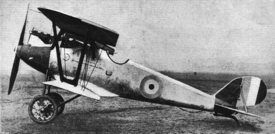
Side view of the Pfalz single-seater fighter, 160 h.p. Mercedes engine.
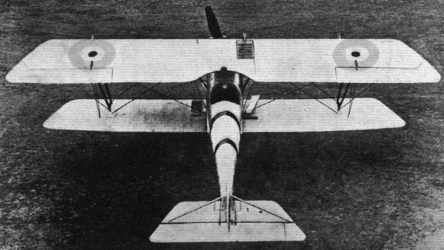
View from above of the Pfalz single-seater fighter, 160 h.p. Mercedes engine.
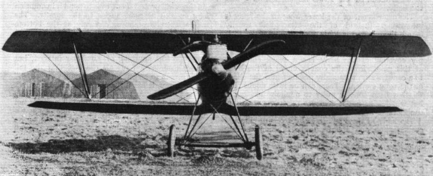
Front view of the Pfalz single-seater fighter, 160 h.p. Mercedes engine.
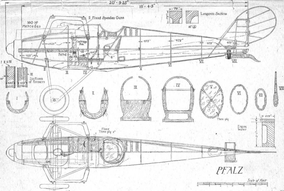
Fig. 1. - Side elevation and plan of the Pfalz body to scale.
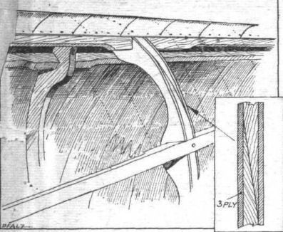
Fig. 2. - Sketch showing construction of body former and attachment of longeron.
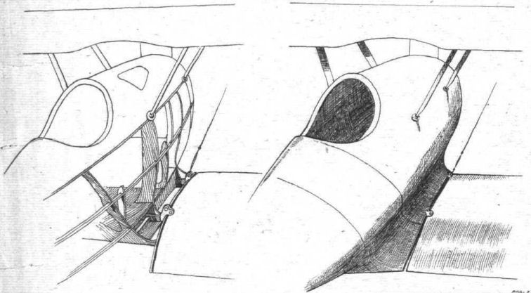
Fig. 3. - The wing roots are formed, on the Pfalz, integrally with the body. On the left is shown the construction of these roots, and on the right the final shape.
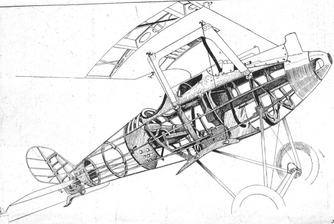
Fig. 4. - Perspective view of the Pfalz body, stripped of its ply-wood covering.
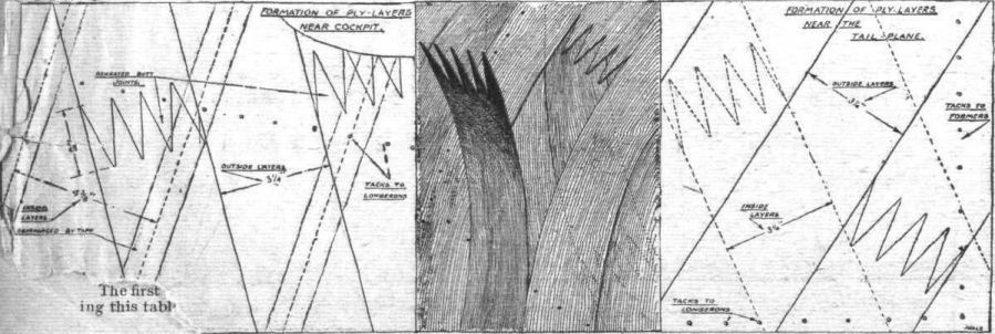
Fig. 5. - <...> showing method of covering with ply-wood the body of the Pfalz.
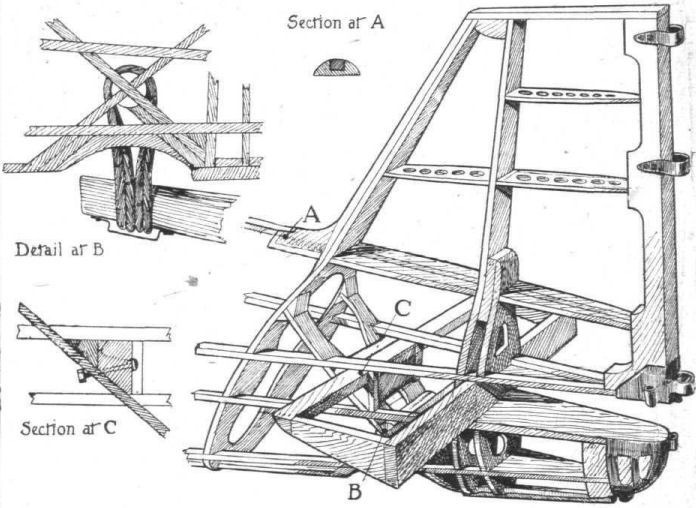
Fig. 6. - Sketch showing mounting of the tail plane root on the Pfalz. The plywood covering of the root has been omitted for the sake of clearness.
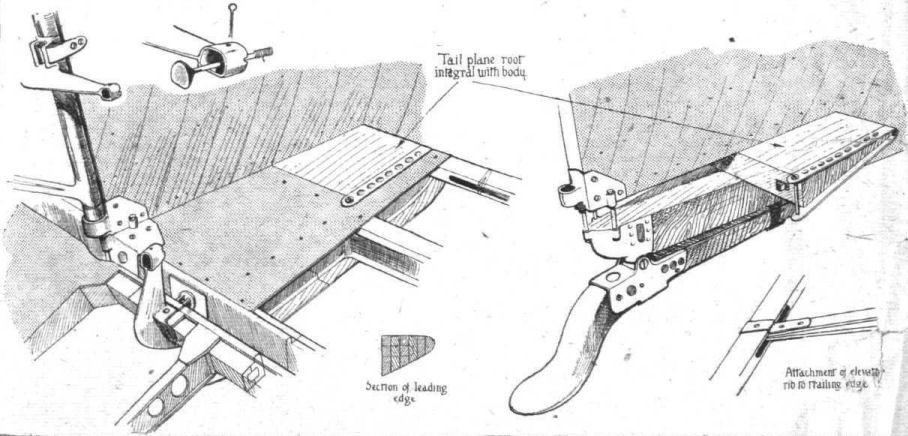
Fig. 7. - Some tail plane details of the Pfalz.
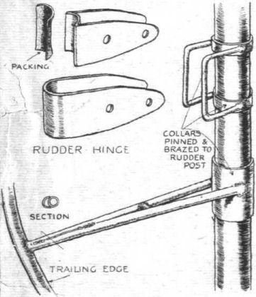
Fig. 8. - The rudder of the Pfalz is built up of steel throughout. The sketches show the main features of the detail construction.

Fig. 9. - Sketches showing safety-belt attachment on the Pfalz
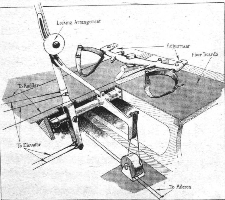
Fig. 10. - Perspective drawing of the Pfalz controls. Note the adjustable foot-bar arrangement.
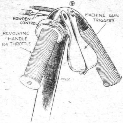
Fig. 11. - The control handle of the Pfalz biplane. The left-hand handle is rotatable, and operates the throttle via Bowden cable.
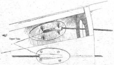
Fig. 12. - Guide tubes for the rudder and elevator control cables of the Pfalz biplane.

Fig. 13. - Sketch showing the nose of the Pfalz body, with "spinner,'' air scoops and inspection doors.

Fig. 14. - Sectional view of the stream-lining of the axle on the Pfalz biplane.

Fig. 15. - Details of the Pfalz undercarriage. In the centre a general view of the undercarriage.
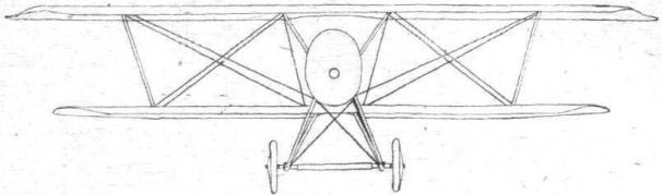
Fig. 16. - Wiring Diagram of the Pfalz Single-Seater. The bracing of the centre-section struts does not run across the top of the body.
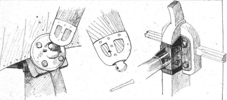
Fig. 17. - Attachment of centre section struts to body on the Pfalz.
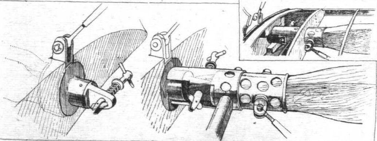
Fig. 18. - Quick-release attachment of lower wing spars to fixed wing roots of the Pfalz single-seater.
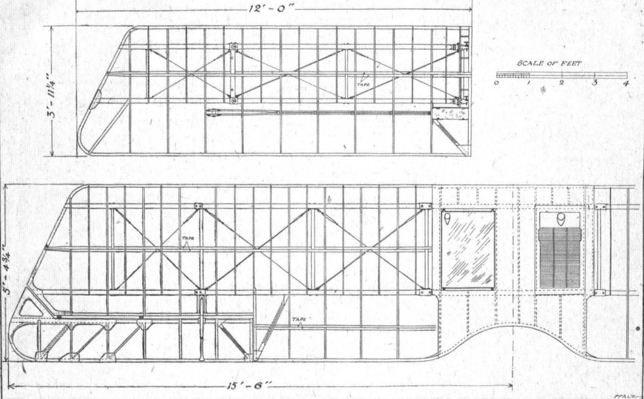
Fig. 19. - General arrangement of the wings of the Pfalz.

Fig. 20. - Upper and lower wing sections of the Pfalz. Inset sections of the wing spars.

Fig. 21. - Attachment of centre-section struts to top plane of the Pfalz. On the right the fitting is shown from a different point of view. The inset shows the wiring lug plate, which also serves as a guide for the end of the compression tube.
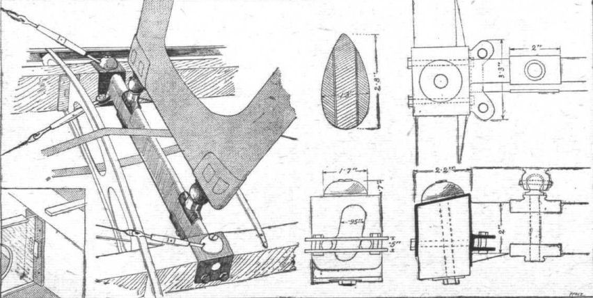
Fig. 22. - Details of the attachment of inter-plane struts to lower plane of the Pfalz single-seater. The smaller insets show a section of the inter-plane struts and - in the left-hand corner - the attachment of the wing ribs to the spars. The top flange is shown cut through so as to show the details below.
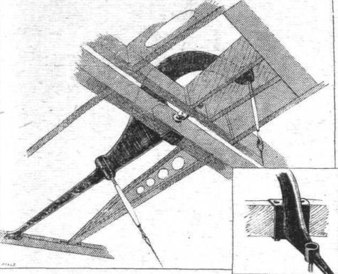
Fig. 23. - The aileron crank lever of the Pfalz.
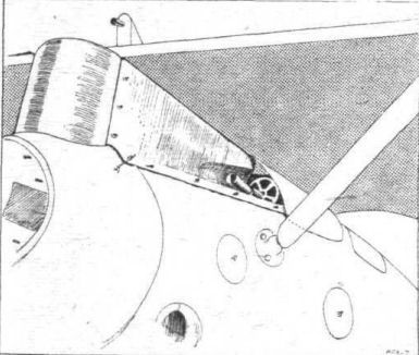
Fig. 24. - The machine-guns on the Pfalz single-seater are totally enlosed, with the exception of the muzzle. Note the scoop in the engine housing.
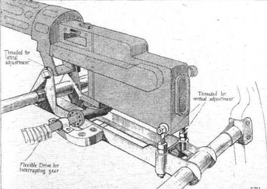
Fig. 25. - The mounting of one of the two synchronised Spandau machine-guns which constitute the armament of the Pfalz.
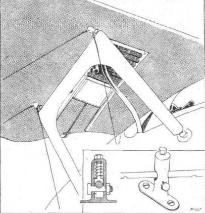
Fig. 26. - The radiator of the Pfalz is mounted in the top plane, and the cooling is varied by means of a shutter. The details of the locking device which enables the shutter to be left in any desired position are shown in the inset.
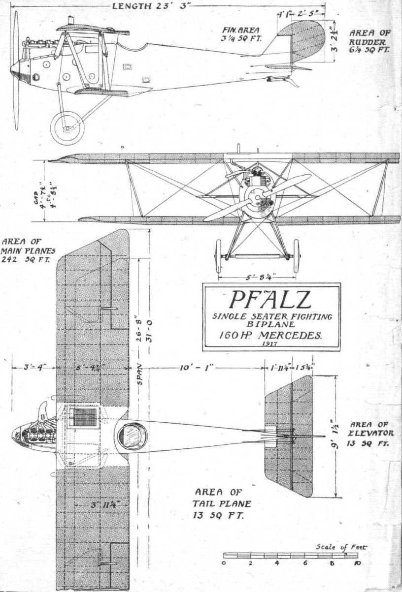
THE PFALZ SINGLE-SEATER FIGHTER. - Plan, side and front elevation to scale.
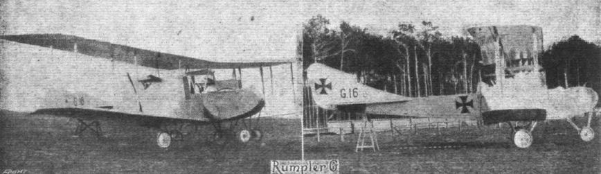
It appears that the Gotha and Friedrichshafen firms are not having a monopoly in twin-engined bombers, the above illustrations showing a machine produced by the Rumpler firm. - From the numbers painted on the fuselage it appears that this machine was built as long ago as 1915.

Flight, February 21, 1918.
THE C.IV RUMPLER BIPLANE.
THE Rumpler biplane described below belongs to the C class of enemy aeroplanes. That is to say, it is a general utility machine, and is perhaps the best in its class. It is chiefly of interest on account of its great speed, which is equal to that of a chaser single seater, and also on account of its high "ceiling" (6.500 metres). This capacity for flying at great altitudes has led the German aviation services to employ a special respirator adopted recently. The climb of the Rumpler C. IV is also very good (5,000 metres in 35 minutes).
Wings. - Both upper and lower wings are swept back 3 degrees. There is a dihedral angle of 2 degrees and the wings are staggered forward 0.60 metres. The trailing edge, contrary to usual German practice, is rigid. The ribs, which are made of three-ply wood, pierced for lightness, are spaced 0.30 metres apart. Their angle of incidence is uniform and is equal to 5 degrees.
In plan the upper wings are of trapezoidal form, with rounded angles. Above the fuselage, the trailing edge is cut out as shown in the illustrations. The maximum chord is 1.70 m. In each of the upper wings there are 19 main ribs, and five compression struts of steel tubes. The ailerons are of the tapering type, their chord varying from 0.50 to 0.65 m. The lower wings, as in so many other German machines, have rounded wing tips. As the radius of the arc forming the rear edge is longer than that of the front, the wing tip resembles somewhat that of a propeller blade. Each of the lower wings has 17 main ribs, and four steel tube compression struts.
The interplane struts, of which there are two on each side of the fuselage, are oblique. In section, the inner front struts measure 0.105 m., and the rear strut 0.130 m., while the outer front strut measures 0.090 m. and the rear outer strut 0.085 m. The gap between the wings is 1.85 m., and the total lifting surface is 33.5 square metres, of which the upper wng is 20 square metres and the lower wing 13.5.
Tail. - The tail plane, which is not adjustable, is not so deep as in previous types. In plan, the leading edge of the tail plane is approximately a semicircle. This tail plane is supported on each side by struts attached at their other end to the bottom rail of the fuselage. Two other struts brace the tail plane to the vertical fin. The struts under the tail plane are provided with a series of sharp-edged metal points. It appears probable that the object of these is to prevent the landing crew, when wheeling the machine about, from catching hold of these struts, thus possibly bending them. The elevator is in two parts, each of which is partly balanced by a triangular forward projection. The rudder, which is built up of metal tubes, is of the usual type, and the control cables pass inside the fuselage, guided at points through small wooden tubes.
The Fuselage. - The construction of the fuselage is of the current type, with four longerons and struts and cross members, braced by piano wire. Front and rear are covered with three-ply wood, and the middle with fabric. The propeller (a Heine) has a diameter of 3.17 m. As on all other German machines, the propeller boss is enclosed in a "spinner."
Engine. - The motor fitted on the Rumpler is either a 260 h.p. Mercedes or a 250 h.p. Maybach, both having six vertical cylinders. When the Mercedes is fitted, it is slightly tilted to the right, in order to allow the induction pipes to pass between the legs of the cabane. With the Maybach, which offers less encumbrance, this arrangement is not necessary. The motor is supplied with fuel from two tanks. The main one (about 220 litres) is placed under the seat of the pilot, the second, the service tank (about 70 litres), is placed at the back of the pilot between him and the gun ring in the gunner's cockpit. The quantity of fuel carried allows of a flight of four hours' duration. The covering over the engine leaves the top of the cylinders exposed, and encloses a Spandau machine gun operated by the motor.
The exhaust pipes run from the six cylinders to a common chimney, curving upwards and backwards. The chimney itself is divided, about half way up, into three branches, probably in order to obtain a certain amount of silencing effect. As in previous models, the radiator, which is semi-circular in shape, is placed on the front legs of the cabane. In front of it is a series of small slats, which can be moved so as to be either parallel to or at right angles to the direction of flight. This is, of course, done in order to make it possible for the pilot to adjust the cooling according to the altitude at which he is flying.
Behind the motor is the pilot's cockpit, and behind him again that of the gunner. Supported on a gun ring in the rear cockpit is a Parabellum machine gun. Pilot and gunner are very close together. In the gunner's cockpit there is a bomb rack of the usual type, carrying four bombs. An opening in the floor permits of taking photographs, and the machine carries a wireless set. The landing chassis is of the V type, with rubber shock absorbers. There is no brake fitted on this machine. An external drift cable runs from the nose of the fuselage to the foot of the inner front interplane strut.
Flight, September 12, 1918.
TWO-SEATER RUMPLER BIPLANE, G. 117.
(260 H.P. MERCEDES 'ENGINE.)
Report by the Technical Department, Aircraft Production, Ministry of Munitions.
THIS machine, which was used by the enemy at the commencement of the year, is of the CV type, but differs only in detail from the earlier C.IV type.
The general shape and disposition of the wings is maintained, including the characteristic sweep-back of the main planes, and the fitting of ailerons to the upper planes only. Some important particulars follow :-
Weight empty (but with water), 2,439 lbs.; weight, fully loaded, 3,439 lbs.; total military load, 545 lbs.; area of upper wings (with ailerons), 217.6 sq. f t.; area of lower wings, 146 sq. ft.; total area of main planes, 363.6 sq. ft.; loading per sq. ft. of wing surface, 9.5 lbs.; area of tail plane, 22 sq. ft.; area of fin, 4 sq. ft.; area of elevators, 20.8 sq. ft.; area of rudder, 6 sq. ft.; total weight per horse-power, 13.2 lbs.; petrol capacity, 59 gallons; oil capacity, 3 gallons; water capacity, 10 gallons; endurance, about 4 hours.
Performance.
ft. m.p.h. revs.
Speed at 10,000 100.5 1,510
Speed at 15,000 87 1,390
Rate of climb
ft. m. s. revs. in ft. per min.
Climb to 10,000 16 0 1,375 400
Service ceiling, 15,500 ft. (estimated).
Estimated absolute ceiling, 17,500 ft.
Greatest height reached, 15,300 ft. in 38 min. 25 sees.
Rate of climb at this height is 125 ft. per min.
Control.
Longitudinal (elevators), good.
Lateral (ailerons), very heavy and very ineffective.
Directional (rudder), moderately light and quite effective.
It is reported that the machine is tiring to fly owing to the very poor lateral control; that it is nose-heavy, and rather liable to get into a spin.
Wings.
The upper wings have a maximum span of 41 ft. 6 ins. and a chord of 5 ft. 8 ins. The span of the lower wings is 40 ft., and the chord is 4 ft. 4 ins.
The wings are swept back through an angle of 3 degrees, and are set at 2 1/2 degrees dihedral angle. The wing sections of upper and lower planes are given in Fig. 1. Bath front and rear spars are of spruce, and are constructed in two halves, which are grooved and tongued, and then glued together. This is clearly indicated in Fig. 2. The ribs are built up of ply wood and strips in the usual manner, and are of good workmanship. Short ribs join the front spar to the leading edge, alternately with the true ribs.
The wing construction appears adequately strong. Steel compression tubes are placed between the spars, and are braced by ties varying from piano wire at the wing tips to cable and swaged rod at the inner end. The trailing edge consists of a flattened steel tube, to which the ribs are attached by copper rivets.
Ailerons are fitted to the upper wing only, which may in some measure account for that ineffectiveness of lateral control which is characteristic of nearly all German aeroplanes. The area of each aileron is 15.3 sq. ft.
The methods of attaching the main planes to the upper cabane and to the fuselage are designed to assist rapidity of assembly and dis-assembly, and are of considerable interest. They do not differ from the arrangement on CIV machines, and may be considered, therefore, to have been found satisfactory in practice. From the Fig. 4 it will be seen that the upper wings are locked by means of a guillotine lever, held in position by a pin passing through both levers and through two holes arranged in the centre section. The lower wings are locked in position by even simpler means (Fig. 3), requiring no moving parts. The ball at the end of the spar is simply introduced into the socket fixed to the fuselage, and the wing tip is kept lowered. When the tip is raised, the top portion of the wing attachment slips into position, thus locking the wing in such a manner that, even before the attachment of struts and bracing, movement is possible in only one way - i.e., by the dropping of the wing tip. A label bearing instructions and an explanatory diagram referring to these lower wing attachments is affixed on either side of the fuselage, near to the socket concerned.
Struts.
These are of circular section steel tube, encased in a wood fairing. A typical Rumpler strut attachment is shown in Fig. 5. The twin sockets are held down by two bolts, which pass right through the spars. The heads of these bolts are clearly shown.
The construction of the welded-up centre section cabane may be gathered from the photographs and from Fig. 6.
A cylindrical well of 3-ply and aluminium is incorporated in the lower wing close to the fuselage on the left side to accommodate the compass, which is thus convenient to the pilot's sight. Fig. 7 shows the construction of this well.
Fuselage.
The fuselage is a compromise between the several rival methods of construction. Wooden longerons and struts, braced with piano wire; steel tubes, and 3-ply are all used in varying degrees.
A braced girder of longerons and cross struts constitutes the principal factor, arid this construction is depended upon entirely in the rear of the observer's cockpit. Towards the tail, for a distance of about 6 ft. from the sternpost, the covering is of 3-ply, which thoroughly stiffens up the fuselage where the stresses due to the tailplanes may be most severely felt. The middle portion of the fuselage sides - i.e., between the 3-ply at the rear and the pilot's seat-has fabric covering, while forward of this 3-ply is again used.
The slightly arched top fairing is entirely of 3-ply, except for the aluminium cowl, which extends to the rear of the gunner's cockpit, as also is the bottom of the fuselage. The engine cowls are of aluminium, held in place by turnbuttons. From the rear of the observer's cockpit to the front of the pilot's seat the wood construction is reinforced by steel tubes, which have forked ends, and are bolted together.
The pilot's cockpit is particularly roomy and comfortably fitted. The gunner is provided with a seat of the piano-steel type with a rotatable head. This head is fixed on its shaft eccentrically, as may be seen by Fig. 8.
Landing Gear.
The undercarriage, of the usual V-type, while presenting few noteworthy features, is of workmanlike design and construction.
Both front and rear limbs are of stream-line section steel tubing. The upper extremities are placed well apart. At the lower extremities the tubes are welded together to form, together with the sheet steel axle fairing, the slot to accommodate axle travel. (See Fig. 9.) The front limb, which is of smaller section than the rear tube, is additionally faired with wood, while the rear limb is naked. The wood fairing has obviously been fitted as an after-thought, and not by the manufacturer. The job is clumsy and without finish, though effective. Landing shocks are taken by the familiar steel coil spring.
Four bracing wires are employed, connecting all four upper attachment points to the apices of the vees. Fig. 10 shows one of the front joints.
Tail.
The tail is practically of standard Rumpler - and, indeed, German - practice, but it is noteworthy that the elevators, which were of the balanced pattern in the CIV machine, are no longer so. As the longitudinal control is reported entirely satisfactory, it is evident that unbalanced elevators have been found all that is desired. The fin may hardly be regarded as adequate, in view of the side area presented in the nose of the machine, and the report that this aeroplane is somewhat liable to spin should be considered in this connection.
The four tail stays are of stream-line steel tube, and the lower pair have serrated edges to assist mechanics in remembering that these stays should not be grasped in lifting the machine or in holding it back on starting.
Although the fabric has not been removed, these members - the fin, rudder, and elevators - appear to be constructed of light steel tube welded in the usual way.
The tail skid is of ash, pivoted in the centre, and sprung at its upper end. The lower end carries a sheet steel shoe, whose shape is shown in Fig. 11.
Controls.
The control system is of considerable interest, inasmuch as the usual transverse rocking shaft operating the elevator controls is not used. The aileron control is actuated by a longitudinal rocking shaft of steel tube, which carries a welded cone-shaped portion supporting the vertical control lever. The aileron cables are attached to a lever pinned to the rocking shaft, and pass through the wings, operating the ailerons in the way that has become usual in German aeroplanes - i.e., the aileron lever lies in line with the plane, and is accommodated in a slot cut in the rear edge of the main plane.
The control cables pass over pulleys when they leave the lower plane to be attached to the aileron lever. These pulleys are situated behind the rear outer strut attachment, and are capped with a neat aluminium fairing.
The control lever operates the cables attached to the elevator levers, those attached to the lower extremities of the levers passing over pulleys mounted in the front portion of the rocking shaft. This shaft projects somewhat below the level of the fuselage bottom, and is neatly faired off by an aluminium shield screwed to the fuselage. The control system should be made clear by Fig. 12.
A welded sheet steel rudder bar of simple pattern, shown in Fig. 13, operates the rudder through the usual cables. The distance between the seat and rudder bar is not variable. Rubber sleeves and leather straps on either extremity guard against the possibility of the pilot's feet slipping.
Armament.
The pilot controls the fire of one fixed Spandau gun attached close to starboard side of the engine. The cocking lever is placed just outside the cockpit to the pilot's right. The gun itself is inaccessible during flight. A thumb lever shown in sketch (14) controls the fire through the usual clutch and synchronising gear.
The observer's gun is of the Parabellum type, and is mounted on the usual built-up wooden gun-ring, of the same kind as that found on most German machines.
Provision for the fitting of a bomb rack had been made, but none was fitted.
An aluminium tray with holes for 10 Verey lights was fixed to the fuselage.
Engine.
Rumpler is usually fitted with a 240 h.p. Maybach engine or a 260 h.p. Mercedes. The present example has 6 cylinder Mercedes of 260 h.p., which possesses the familiar combined throttle and altitude control. The exhaust gases are led into a welded manifold, the shape of which is indicated in the photograph.
Cooling System.
The radiator, made by Hans Windhoff, is slung over the rear portion of the engine, and fixed to the central cabane. (For photograph of the radiator and connections of the 2-seater Rumpler see Fig. 33 in the description of the Maybach engine, page 1035.) The honeycomb consists of circular brass tubes, expanded at their extremities into hexagons, and sweated together there. The total radiating surface is approximately 1.5 sq. ft. The shutters which regulate the cooling surface are shown in Fig. 15. They, are operated by cables passing over pulleys. One cable passes over the top of the radiator, while the other exerts a downward pull and passes underneath. German pilots have reported that these shutters are rarely required except during protracted descents.
The temperature of the water is indicated by a mercury thermometer easily visible from the pilot's seat, and the limits of the permissible range of temperature are defined by red marks-one at 60 degrees and the other at 85 degrees. The radiator may be considered thoroughly satisfactory, but must naturally obstruct the pilot's view to some extent.
The oil tank is situated at the port side of the engine, and the maintenance of an equable temperature of its contents is assisted by a thick covering of felt. The oil pump is embedded in the bottom of the crank case, and not only passes on the oil to the gudgeon pins and crankshaft, but at the same time mixes, at each pulsation, a certain quantity of fresh oil from the tank with the oil already in circulation.
Petrol System.
The main petrol tank - of 46 gallons capacity - serves as a support for the pilot's seat, while an auxiliary tank holding 13 gallons is fitted between the two cockpits, adapting itself to the shape of the fuselage top fairing and to the gunner's turret. Neither tank seems to possess baffle plates, and both work under pressure.
The initial pressure is obtained by means of hand pumps, of which there is one in each of the cockpits. An automatic air pressure pump driven off the crankshaft maintains the pressure, and a release valve incorporated in the pump regulates it. Each tank has its own pressure gauge on the dashboard. The petrol gauge on the main tank is of Laufer make, while a Maximall gauge is found on the auxiliary tank. All pipes on this machine are of copper, and the tanks of sheet brass.
Engine Controls.
Three 3-way cocks are fitted. They enable the pilot to shut off the petrol entirely; to supply from both tanks simultaneously, or to run on either of the tanks alone. The throttle controls are shown in Fig. 16. The placing of the Mercedes carburettor at the rear of the engine facilitates the direct nature of the control.
The Deuta tachometer, working on the centrifugal principle, is driven off the camshaft, and is graduated from 0 to 1,600 r.p.m. It is not illuminated, and no normal is marked.
Propeller.
The propeller is an "Axial," No. 6987, diameter 3,150 mm., pitch 1,830 mm. It is secured to the crankshaft by eight bolts, an extra pair being fitted between two of the pairs of the usual six.
Wireless.
The machine is internally wired, and a tapping key is fitted to the gunner's right hand. The rack intended to support the aerial reel is also to be found, as well as a sheet steel dynamo shelf near the engine.
Cameras.
Two types of cameras were fitted. One particularly large one was accommodated in the special fitting shown in Fig. 17. The light octagonal tray A is suspended from the floor boards by elastic shock absorbers.
The zinc well shown in Fig. 18 carried the second camera. A light ply-wood tube, 30 in. long and 5 in. wide, is fixed to the rear of the observer's seat. It is obviously intended to carry some object, probably a Goerz bombing sight.
This machine is now at the Enemy Aircraft View Room, Agricultural Hall, Islington, where it may be seen on production of a pass, obtainable from The Controller, Technical Department, Ap.D.(L.), Pen Corner House, Kingsway, W.C. 2.
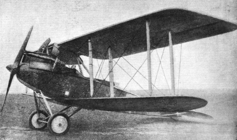
THE C. IV-TYPE RUMPLER BIPLANE. - Three-quarter front view of the 260 h.p. Mercedes D.IVa model.
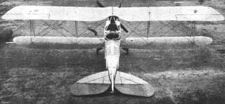
Rear view of the 2-Seater Rumpler.
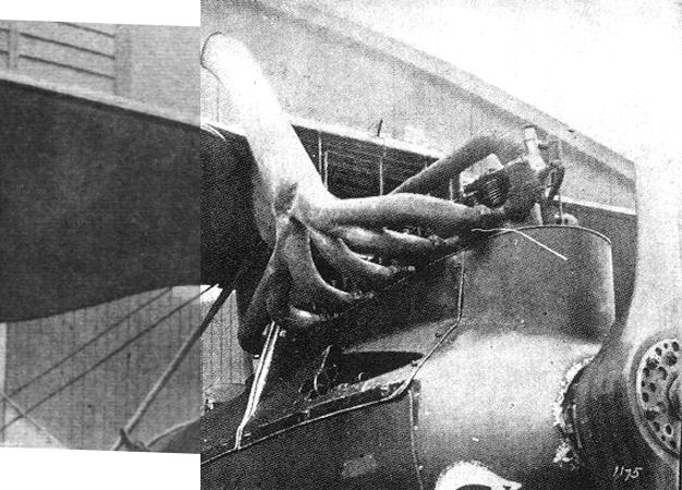
The exhaust manifold and engine cowling of the 2-Seater Rumpler.
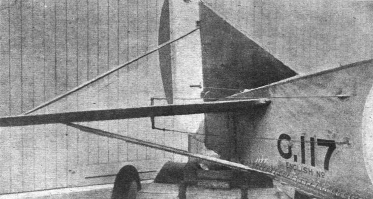
Tail and Fin Bracing of the Rumpler. Note the saw-teeth on the low tail stay type to prevent mechanics from lifting the machine by this tube.View of the 2-Seater Rumpler tail.
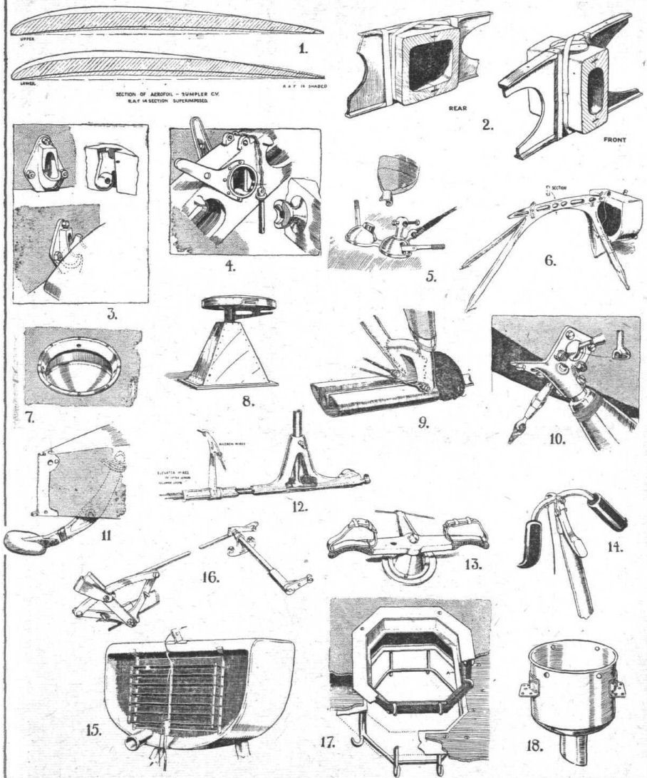
THE 2-SEATER RUMPLER, C. 5 TYPE. - Figs. 1 to 18.
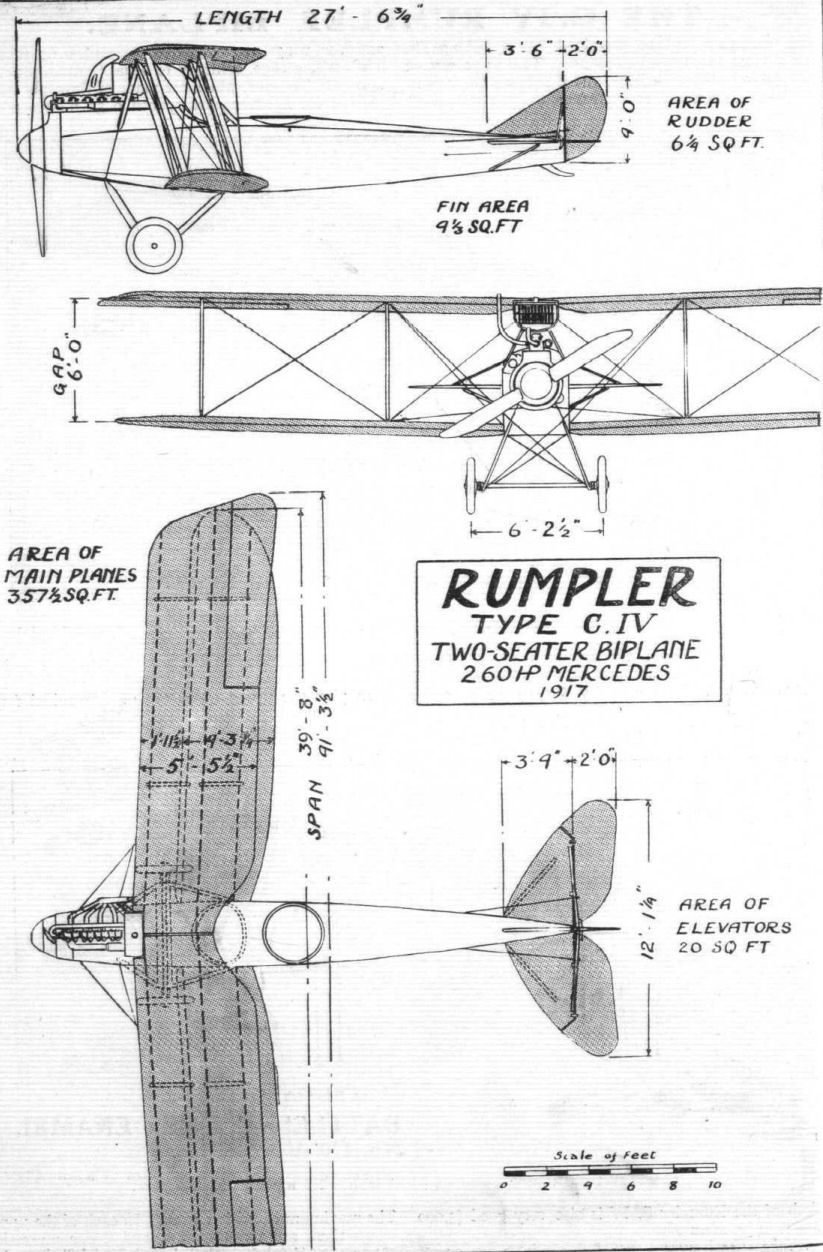
THE C.IV-TYPE RUMPLER BIPLANE. - Plan, side and front elevations to s:ale.
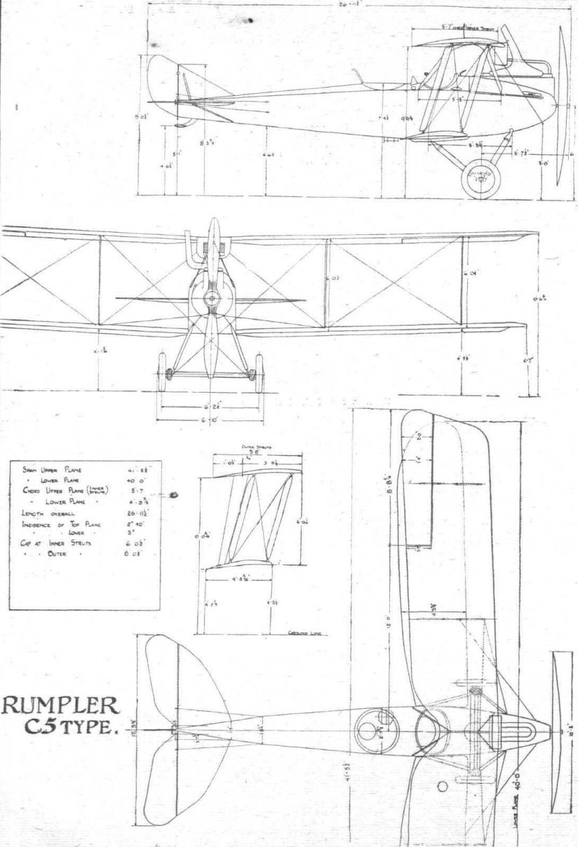
THE 2-SEATER RUMPLER, C. 5 TYPE. - General arrangement to scale.
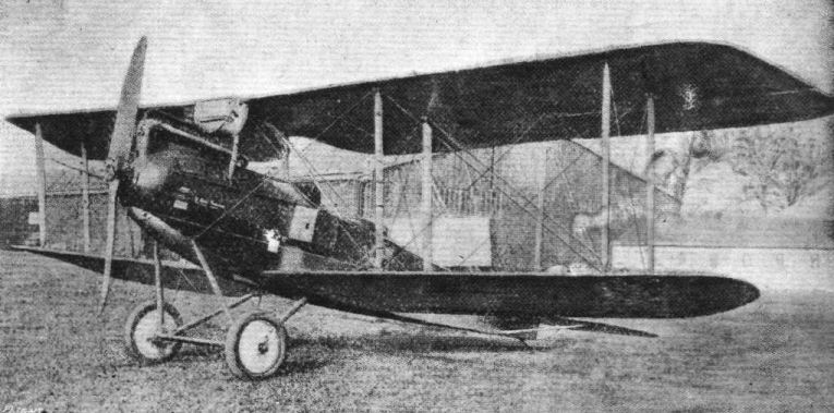
The C. IV-type Rumpler biplane fitted with a 250 h.p. Maybach engine.
Flight, September 26, 1918.
A NEW GERMAN "CHASER."
THE SIEMENS-SCHUCKERT BIPLANE.
THE following is a translation of an article published in Le Matin of August 18th :-
"The reverses which the Germans have suffered with their 'chasers,' which since last March have been very much inferior to those of the Allies, have led them to venture into new designs.
"Some time ago we have remarked upon the new Fokker D VII biplane, whose fighting value is far below that of the Allies' fighting 'planes. Our enemies have also put into service the Halberstadt C II fitted with a 160 h.p. motor (Mercedes). They hoped to make a record with this machine, but they were forced to recognise that the relatively slow speed of the machine - 165 kilometres per hour - its great weight of 45 kgs. per square metre of carrying surface, made it inferior to our machines in speed and handiness.
"For some little time the Germans have placed in their fighting squadrons a few of the new Siemens-Schuckert biplanes, fitted with a rotary motor, eleven cylindered, and giving 260 h.p.
"The Siemens-Schuckert workshops which are producing this new chaser also construct large bombing machines of the Lizenz type with three or five motors.
"This 'chaser,' with a span of 7 metres and 6 metres in length, is short and squat in appearance. To obtain stability it has been necessary to fit a fixed plane to the tail, and to have an elevator of large dimensions.
"The upper and lower planes are of the same span, and balanced ailerons are fitted to both planes. The upper plane is rectangular in shape; it is made in one piece, but cut away to allow the pilot a better view. The lower plane is staggered to the rear, but it is of smaller chord than the upper wing.
"The rotary motor of 260 h.p. moves a four-bladed propeller after the English fashion. Certain 'planes of the same type are fitted with the modified 260 h.p. Mercedes.
"The armament consists of two machine-guns firing together or separately, through the propeller.
"The Germans say that this aeroplane is very easy on controls and that it 'stunts,' and in particular 'cartwheels' and 'loops' with surprising ease. They also say that its climbing speed is excellent, and that it climbs to 6,000 metres in 15 minutes. They have said the same of their Pfalz, their Fokkers, and their Halberstadts, that one is tempted to believe that they take their ideals for realities!
"But what must be remembered is the haste with which the Germans have tried to invent and to construct new machines in order to recover a little of the prestige of their air services which has been in a bad way for the last six months. The construction and transport has not been without difficulty. Witness the orders for the 40th Division :-
"'The slowness which is found in the replacing of aeroplanes and in the repair of existing machines, and the everincreasing difficulty of recruiting the personnel of the air services, oblige us to economise in our air forces. The forces will be directed with the distinct intention of refusing to participate in any mission which is not of primary importance in the war. This severe discipline, necessary because of the artillery action (which ought not to be held up for an instant during the present artillery duel), will not permit the use of battle planes for a moment longer than is absolutely necessary.'"
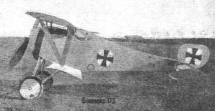
The Siemens Single-Seater. From the fact that It is said to be the type D I, and a publication of the illustration in a German paper has been allowed, it appears improbable that this is one of the Siemens-Schuckert machines of which a good deal in now heard are seen on the Western Front. The machine has a distinctly "Nieuporty" appearance.
Flight, November 28, 1918.
NOTES ON GERMAN BOMBERS
THE FOUR-ENGINED GIANT
[Issued by Technical Department (Aircraft Production), Ministry of Munitions.]
(Continued from page 1322.)
THERE are known to be a number of different types of giant bomb-carrying aeroplanes, distinguished by the four, five, or six engines with which they are fitted.
Examples of four-engined and five-engined aeroplanes have been brought down, but unfortunately, in all cases, in such a damaged condition that complete reconstruction is impossible.
The following particulars relate to a four-engined machine which landed near Betz on the night of June 1st.
It was almost completely burnt by its occupants, and the metal parts alone remain, together with a few fragments of the body work.
The general arrangement of this aeroplane, together with the principal dimensions, is given in the accompanying drawings (Figs. 42, 43, 44 and 45).
In contradistinction to the two-engined machine, there is considerably more steel in the construction, and this material is used in place of wood for the rear portion of the fuselage.
The principal point of interest is the mounting of the four engines, all of which are of the 260 h.p. Maybach type, six cylinders in a line; the horse-power has been forced up to 300, giving 1,200 h.p. in all. They are placed end to end, as shown in Fig. 46, and each drives a separate screw.
In order to bring the centre of gravity of the machine sufficiently far forward, the weight of the two engines is massed towards the leading edge of the main plane; by driving the screws through shafts and reduction gears, the necessity of cutting away large sections from the planes to give room for the rear propellers has been avoided.
The arrangement of the engine unit on each side of the fuselage is diagrammatically shown in Fig. 46, from which it will be seen that the two engines are placed close together, and that the rear motor is some little distance away from its screw. The forward engine is, however, mounted close up to the tractor screw.
The employment of shafts and reduction gears necessitates fly wheels on the engines. These are 4 metre in diameter, and made of cast iron. The tubular driving shafts between the fly wheel and the gear box are furnished with flexible leather couplings. These are of a novel type, and consist of a male and female drum, each furnished with circumferential notches, between which are interposed a series of flat leather strips. The female drum forms part of the fly wheel.
The gear box consists of a casing of aluminium, provided with cooling fins, which may be seen in Figs. 47 and 48.
Beneath each gear case is a small radiator for cooling the lubricating oil circulated through the engine. This radiator can be seen in Fig. 47, and consists apparently of a flat semicircular tank, fitted with numerous transverse tubes of fairly large diameter (about 20 mm.) in a manner similar to that of a honeycomb radiator. A pump mounted at the base of the radiator is also furnished with an electrical thermometer, giving a reading on a dial in the cockpit.
Each engine is fitted with a self-starting arrangement of the type usually fitted to Maybach motors. The exhaust pipe may be closed by means of a shutter, and all the cylinders can be filled with gas from the carburettor by means of a large hand-pump, for which purpose all the valves are held open. When these valves are closed, and the starting magneto operated, the engine fires and continues running. Each engine has its own radiator (Fig. 49), which is mounted directly above it, and supported by struts and stay wires at a point about half-way between the top and bottom planes. These radiators are of the type usually fitted to D.F.W. machines. They are rectangular in shape, with their greater length placed horizontally, and the radiating surface consists of a series of zig-zag tubes placed vertically.
The engine bearers consist of stout ash spars, reinforced with multi-ply wood. Owing to the burnt condition of the machine no information could be obtained as to the engine controls and the screws were also too badly damaged to yield definite information as to dimension and construction, though they appear to be made chiefly of ash and covered with a thin veneer.
Wing Construction.
The spars are shown in Fig. 50, built up very elaborately in sections, and consisting of no less than seven sections of spruce, reinforced with multi-ply on each side, and finally carefully bound with doped fabric.
The spars of the lower wings are continuous, that is to say, they run right across the centre section of the fuselage, to the longerons of which they are secured, contrary to the usual practice, in which special compression members, forming part of the fuselage construction, are employed. The wing surface, both upper and lower, is divided into three sections of which the middle section extends to the engine mountings on each side. The spars in this section are both at right angles to the axis of the fuselage. At each side of the middle section the leading edge of the wings is boldly swept back as well as tapered. The rear spars of the wings, together with those of the centre section, form a straight line from wing-tip to wing-tip, but the front spars are swept back.
The ribs, of which a detail drawing is given in Fig. 51, are built up, and of girder form.
Between the leading edge and the leading spar, numerous extra ribs occur in addition to the main ribs. Internal bracing against drag takes the form of steel tubular compression members and steel cables, the former being placed at a point coincident with the attachment of each interplane strut. An additional bracing is installed, of which the compression member consists of a double rib placed half-way between the struts. In each case the bracing wires pass obliquely right through the spars.
The ribs are mounted parallel to the line of flight.
The disposal of the spars is as follows :-
Top Plane. -
Leading edge to centre of leading spar 1 ft. 9 1/2 ins.
Distance between centres of spars 5 ft. 7 1/2 in.
Trailing edge to centre of rear main spar 5 ft.
Bottom Plane.-
Leading edge to centre of leading spar 1 ft. 7 1/2 ins.
Distances between centres of main spars 5 ft. 1 in.
Trailing edge to centre of rear main spar 5 ft. (approx.)
The trailing edge of this aeroplane was too badly damaged to permit of this measurement being given accurately.
Between the interplane struts the rear spars are thinned down in width, but their depth remains practically constant from root to tip. Such tapering as exists is so arranged as to promote a decided wash-out of the angle of incidence near the tip. This is done by tapering the front spar on its upper edge, and the rear spar on its lower edge.
Ailerons
These are on the top planes only, and are provided with a framework of steel tubing. They are not balanced, and the controls are led in the usual manner through the bottom plane from the aileron lever.
The span of each aileron is 22 ft. 5 ins., and the chord 3 f t . 4 ins.
Inter-plane Struts
These are of large-diameter steel tube, covered in with a streamline fairing consisting of three-ply mounted on a light rib-work of wood.
Bracing
The attachment of the bracing cables to the spars is somewhat similar to the bracing of the Fokker fuselage; that is to say, the wires, instead of being anchored at each end to an eyebolt, are double, and are looped round the spar, to which is fixed a grooved channel-piece for the reception of the cable. It is difficult to see that any advantage is gained by this arrangement.
Tail Unit
A biplane tail, somewhat similar to that of the Handley-Page, is fitted. The fixed tail planes, the angle of incidence of which can be adjusted through small limits, are of wooden construction, and have the following dimensions :-
Span each side of fuselage 12 ft. 4 ins.
Chord (average) 4 ft. 10 ins.
Gap 6 ft. 9 1/2 ins.
Elevators
These are fitted to both the top and bottom tail planes, and are of aluminium construction, the ribs, being of girder form, somewhat similar in construction to the ribs of the main planes. The elevators are not balanced ; the top and bottom elevators are fitted with independent control levers, but are presumably operated together from the control stick. Their dimensions are as follows :-
Span 28 ft. 6 ins.
Chord at tip 2 ft. 4 ins.
Chord at centre 1 ft. 6 ins.
Fins
There are three fins; two outer ones forming interplane struts, and an inner central one of triangular shape.
Rudders
The framework of these organs is built up of aluminium in the manner set forth in detail in Fig. 52. This also shows the quadrant at the foot of the rudder posts by means of which they are operated; each rudder post is fitted with ball bearings, both top and bottom.
Undercarriage
Beneath each engine section is an undercarriage consisting of a massive axle fitted with four wheels at each end. This isle is attached by india-rubber shock absorbers to the tubular steel V-struts which form extensions of the engine bearer struts. A third undercarriage is mounted under the forward part of the fuselage, and consists of an axle with one pair of wheels.
Armament
Only two gun mountings were found in the wreckage; they were fitted to a revolving turret in the gunner's cockpit. The mountings are of the fork type, and are situated on opposite sides of the circle. No arrangements for firing under the tail were found, nor was there evidence of a forward gun mounting.
Bomb Gear
Two steel tubular frameworks are fitted, one on either side of the fuselage. They are apparently adapted to carry very large bombs, probably of 1,000 kg. each, The release gear appears to be similar to that used on the Friedrichshafen , and already reported upon.
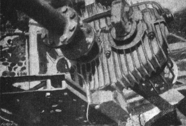
Fig. 47. - Gear box and oil radiator of four-engined giant.
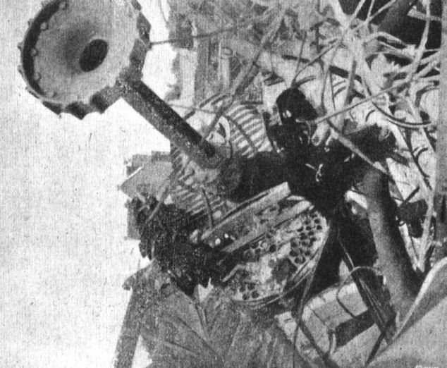
Fig. 48. - Gear-box anf shaft of four-engined giant.
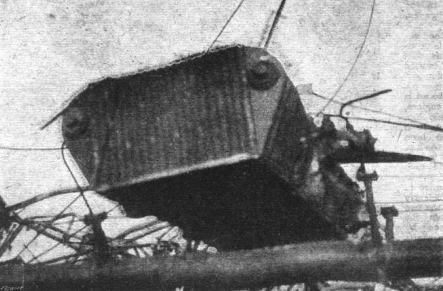
Fig. 49. - Radiator of four-engined giant.
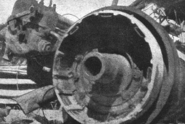
Fig. 53. - Flywheel and female clutch of four-engined giant.
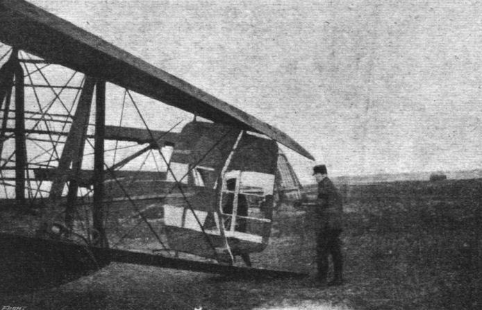
Fig. 54. - Empennage of four-engined giant.
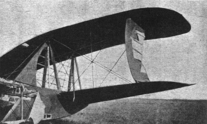
Fig. 55. - Empennage of four-engined giant.
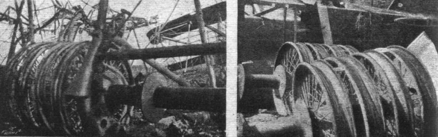
Fig. 56. - Undercarriage of four-englned giant.
Fig. 57. - Axles and wheels of four-engined type.
Fig. 57. - Axles and wheels of four-engined type.
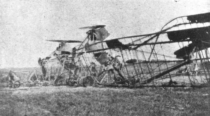
Fig. 58. - General view of wreckage of four-engined giant.
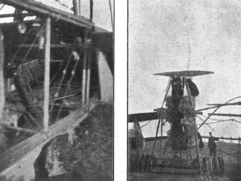
Fig. 59. - Rear end of fuselage and tail-skid of four-engined giant.
Fig. 60. - Power plant of four-engined giant.
Fig. 60. - Power plant of four-engined giant.
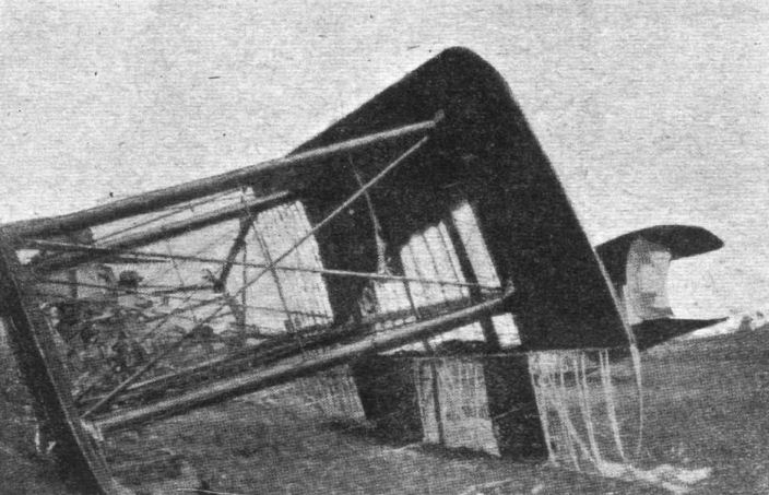
Fig. 61. - Main planes and ailerons of four-engined giant.
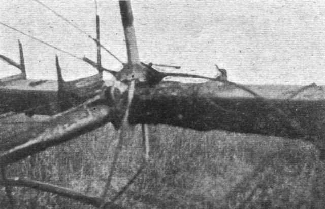
Fig. 62. - Attachment of struts and compression tube on four-engined giant.
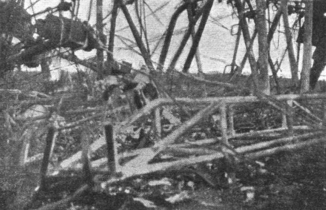
Fig. 63. - Bomb carrier of four-engined giant.
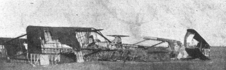
Fig. 64. - General view of wreckage of four-engined giant.

Fig. 46. - Engine mounting of four-engined giant.

Fig. 50. - Spar sections of four-engined giant.
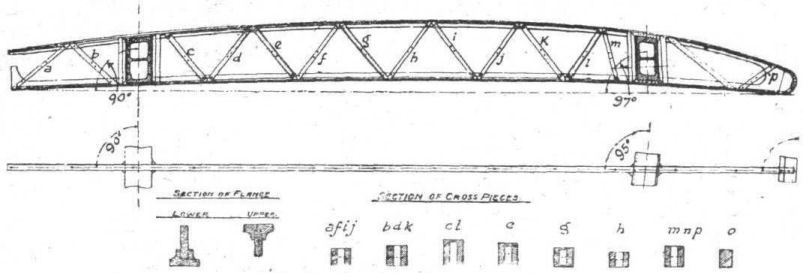
Fig. 51. - Rib of four-engined giant.
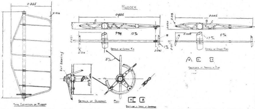
Fig. 52. - Rudder of four-engined giant.
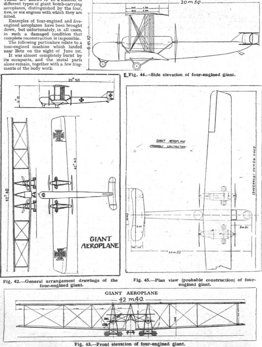
Fig. 42. - General arrangement drawings of the four-engined giant.
Fig. 43. - Front elevation of four-engined giant.
Fig. 44. - Side elevation of four-engined giant.
Fig. 45. - Plan view (probable construction) of four-engined giant.
Fig. 43. - Front elevation of four-engined giant.
Fig. 44. - Side elevation of four-engined giant.
Fig. 45. - Plan view (probable construction) of four-engined giant.
Flight, December 5, 1918.
NOTES ON GERMAN BOMBERS
THE FIVE-ENGINED GIANT
[Issued by Technical Department (Aircraft Production), Ministry of Munitions.]
(Concluded from page 1347.)
A FIVE-ENGINED bomber was brought down near Talmas on 10th, but unfortunately, owing to the explosion of one of its bombs, the machine was damaged beyond hope of reconstruction.
Some of its components have been recovered, and of these photographs are given in Figs. 67 to 82.
The principal item of interest is the gear box, which is used for all five engines, each of which is a 300 h.p. Maybach of the standard 6-cylinder vertical type.
The power plants are arranged as follows :- In the nose of the machine is one engine driving a tractor screw. On each side of the fuselage, supported by the wings, is a long pair of engine bearers carrying two engines apiece, which drive tractor and pusher screws in a manner exactly similar to that set forth in Fig. 46.
The use of the gear box and driving shafts necessitates the employment of a fly wheel on the engine, to which is added the female portion of a flexible coupling of the type already described.
Whereas the gear box in the four-engined giant, of which notes have already been given in this report, is of a somewhat crude type employing external driving shafts between the gear box and the engine, in the five-engined machine the gear-box design is considerably improved. The casing consists, as shown in photograph No. 67, of a massive aluminium casting provided with four feet which are bolted to the engine bearers.
Two kinds of gear boxes are employed. These differ only in over-all dimensions and the length of the propeller shaft.
The larger type is used for the pusher screw in order to obviate the necessity of cutting a slice out of the trailing edge of the main planes.
All the gear boxes were very badly damaged except that which is shown in Fig. 67. This is the longer type, but it would appear that the shorter design is very similar in appearance.
In each case the gear reduction is 21-41.
Plain spur pinions are used having a pitch of 22 mm. and a width across the teeth of 75 mm. The diameter of the smaller of the driving pinions is 162.5 mm., and that of the larger pinion 282 mm.
The larger pinion is as shown in Fig. 73, considerably dished, but the web is not lightened by any perforations.
The over-all dimensions of the gear box, as represented in Fig. 67, is as follows :-
Length, 1,025 mm.; breadth, 675 mm.; height, 535 mm.
The driving pinion runs on two large diameter roller bearings, carried in gunmetal housings supported in the inner end of the gear box. This part is split vertically, and united by the usual transverse bolts, whilst the conical-shaped portion of the box is solid. The usual oil-thrower rings of helical type are fitted.
At its outer end the pinion shaft terminates in a ring o serrations which engage with serrations provided in the male portion of the flexible coupling, these two parts being held together with bolts and clamping plates. The engine is thus close up against the gear box, in contradistinction to the design of the four-engine power plant. There is practically no external shaft at all. The larger pinion is mounted on a hollow shaft of 92 mm. diameter, carried on roller bearings at each end for radial load, and furnished at the nose end with ball thrust bearings.
In the short type of gear box the larger pinion shaft is left solid, and it would appear that the gear box casing, instead of being made in three pieces, is made in two pieces, i.e., the whole box is simply split vertically.
Reference to photograph No. 68 will show that the smaller pinion shaft projects right through the gear box, and at its outer end carries a projection fitted with a small ball thrust race. This projection acts as a drive for the oil pump, which is mounted on the oil radiator used in connection with each gear box.
It is worthy of notice that the German designers have now fully realised the importance of using geared engines for weight carrying aeroplanes, and are apparently satisfied with the external gear-box principle, although in this case they have made it a very ponderous affair indeed. Needless to say, a great amount of the weight could have been saved, if 12-cylinder engines had been used instead of 6-cylinder.
The weights of the gear box and its attachments are as follows :-
Gear box, long type, 280 lbs.
Fly wheel and female clutch, 44 lbs.
Male clutch, 5 lbs.
Oil radiator, 12 1/2 lbs.
This, it will be seen, represents an additional weight of considerably more than 1 lb. per horse power.
The oil radiator used in conjunction with each gear box is of a roughly semi-circular shape, and is slung underneath the main transverse members of the engine bearers so that it comes immediately beneath the large feet of the gear box, as shown in Fig. 69. This radiator is entirely of steel construction, and embraces 65 tubes of approximately 20 mrn, internal diameter. These are expanded and sweated into the end plates, to one of which is fitted a stout flange, against which is bolted a small gear pump which constantly circulates the oil from the gear box case through the radiator.
This gear pump is driven by a flexible shaft from the small pinion, the shaft and its casing being in all respects similar to those employed for engine revolution counters. As shown in the photograph. Fig. 68, which illustrates the complete gear box upside down, this flexible drive is taken off a small worm gear.
It will also be seen that underneath the oil sump of the gear box proper an electrical thermometer is fitted, which communicates with a dial on the dashboard.
It is a little difficult to see what object can be served by this thermometer, unless it be to indicate the desirability of throttling down a little in the event of the oil getting unduly hot, as there is no apparent means of controlling the draught of air through the oil radiator.
Fitted on each gear box and working in connection with the oil circulation is a filter of the type shown in Fig. 75. This is provided with an aluminium case and a detachable gauze cylinder through which the oil passes.
The arrangement of the gear box is such that the axis of the propeller is raised about 220 mm. above that of the engine crankshaft.
The construction of the long engine bearers is not without interest, as amongst other things, it indicates that German manufacturers are finding themselves short of suitable timber. Each bearer, as shown in Fig. 65, consists of a spruce or pine central portion, to which are applied, top and bottom, five laminations of ash. On each side are glued panels of three-ply, about 1 in. thick.
The engine bearers taper sharply at each end, and are strengthened by massive steel girders under each gear box. One of these girders, which is a single-piece welded construction, is illustrated in the photograph, Fig. 77.
The screws revolve at approximately half the speed of the engine, and having therefore a moderately light centrifugal load to carry, are made of a common wood that would scarcely be safe for direct driving screws.
Although fitted to 300 h.p. Maybach engines, they are marked 260 p.s. (h.p.) Mercedes. The diameter is 4.30 meters and the pitch 3.30, for the pusher screw, but unfortunately, owing to the propellers being badly damaged, not only by the crash, but by fire, it is not possible to state whether the tractor screws are of the same dimensions and pitch.
The construction is very interesting; each screw is made of 17 laminations of what appears to be soft pine, and these laminations are themselves in pieces, and do not run continuously from tip to tip. They are, of course, staggered, so that the joints in successive layers do not coincide. Two plies of very thin birch veneer are wrapped round the blades. The grain of this veneer runs across the blade instead of along it.
It is difficult to say from the appearance of the screw whether this veneer has been put on in the form of two-ply or as two separate layers, one after the other.
Among other details salved from the wreckage is the engine control. This is illustrated in photograph No. 76, and is a very massive affair. It consists of five stout steel tubular levers, two of which it will be noticed have become unbrazed in the fire which broke out when the machine crashed.
The levers are fitted with ratchets so that each one can be operated individually, but the presence of the large-diameter toothed wheel in the centre of the lever shaft would seem to indicate that all five levers could, when desired, be controlled simultaneously. This fitting had, however, been very badly fused, and it is impossible to give details with certainty.
A smaller fitting recovered from the wreckage is illustrated in photograph No. 71, and consists of a windmill of a type similar to that used on the D.H. 9 aeroplane. It is mounted at the top of an aluminium tube, but it is not possible to say for what purpose this mill is employed.
A small and very heavy rotary pump, found in the wreckage is shown in photograph No. 71. This is possibly the hand-driven petrol pump, though it would appear unusually massive for this purpose.
The Douglas type of engine, carried for the purpose of driving the dynamo of the wireless and heating installation, is illustrated in photographs No. 78, 80, 81 and 82, which show various views of the motor and generator. The engine is a very close copy of the 2 3/4 h.p. Douglas, and is made by Bosch. The fly wheel, as shown in photograph No. 80, is furnished with radial vanes which induce a draught through a sheet-iron casing, and direct it past cowls on to the cylinder heads and valve chests.
The generator is direct-driven through the medium of a pack of flat leaf sprints, which act as dogs, and engage with the slots on the fly-wheel boss, as shown in Fig. 82.
What appears to be a transformer, used in conjunction with the wireless set, is illustrated in photograph No. 79.
The ponderous tail skid of this machine is illustrated in Fig. 66. It is built up of laminations of ash, and furnished with a heavy steel shoe and a large universal attachment.
Special Note.
A complete and detailed report on the above-mentioned gear box, giving the fullest possible information and analysis of metals, etc., will shortly be published.
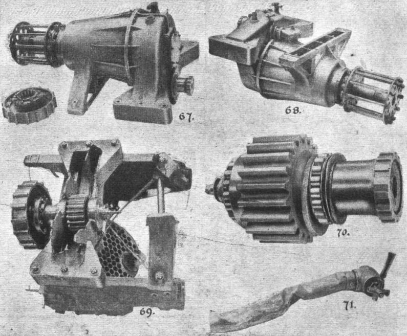
Some constructional details of the five-engined giant. - 67. Long gear box, complete with male clutch. 68. Long gear box seen from underside. 69. Broken gear box (long type), with bearers and oil radiator. 70. Driving pinion. 71. Windmill.
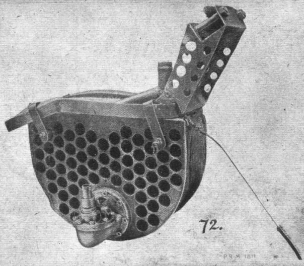
Fig. 72. - Oil radiator and gear pump of five-engined giant.
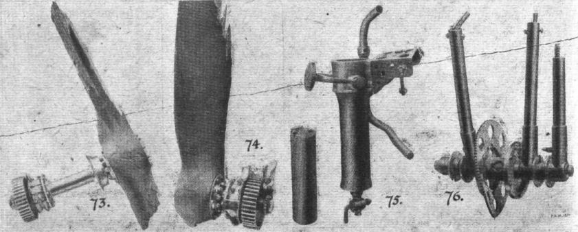
Some more details of five-engined giant. - 73. Pusher screw and driven pinion. 74. Tractor screw and pinion. 75. Oil filter of gear box. 76. Engine control levers.
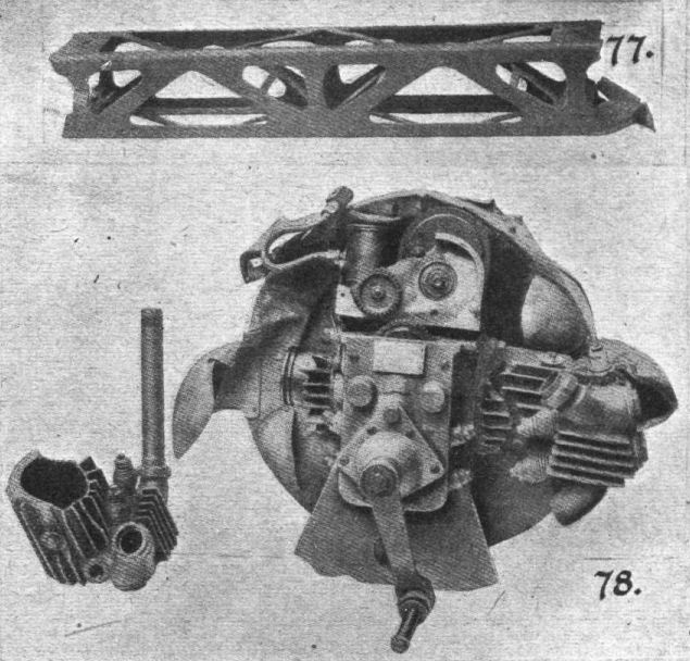
Fig. 77. shows engine bearer transverse-girder. 78. "Douglas" type wireless and heating generator.

The five-engined giant. - 79. Pump and transformer, 80. Rear view of engine and flywheel. 81. Wireless generator. 82. Cowling and dynamo drive.
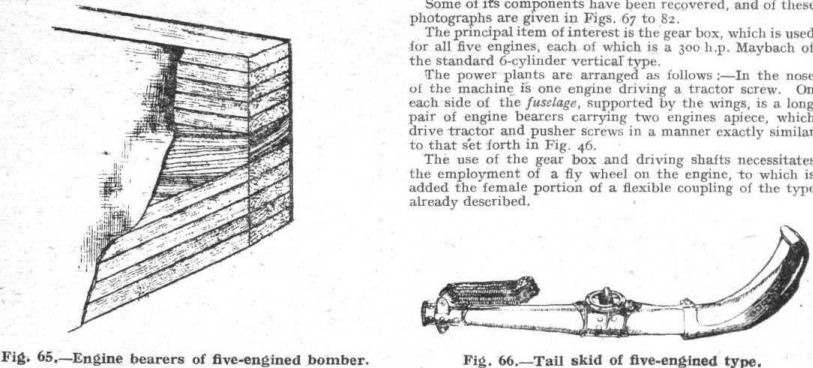
Fig. 65. - Engine bearers of five-engined bomber.
Fig. 66. - Tail skid of five-engined type.
Fig. 66. - Tail skid of five-engined type.
Flight, February 7, 1918.
FROM OTHER LANDS.
THE S.V.A. FIGHTING SCOUT.
A LITTLE while back we reproduced two views of the Italian S.V.A. Fighting Scout, and this week we are able, through the courtesy of our American contemporary Aerial Age, to give further illustrations and some particulars of this machine.
"The S.V.A. machines are manufactured by Gio. Ansaldo and Co., of Genoa, in a number of types quite similar to one another, the principal differences being in the wing spread and weight. In nearly all the types, the same propeller, motor and fuselage are used. With the exception of one of the types, the interplane strut bracing at either side of the body is arranged in the form of the letter N. The machine illustrated here is convertible for water use by replacing the landing gear with twin floats, as illustrated in one of the accompanying views.
"All the material used in the construction of these machines is tested in laboratories before being installed, and again rigidly inspected when the machine has been tested out in actual flight. The woods are tested for transverse and longitudinal tension and compression, &c. Cables are from eight to ten times as strong as calculations show them to be necessary under extreme conditions. The silk-linen covering is somewhat transparent, and after being treated with dope is practically untearable. Every piece of fabric and all the materials are submitted for examination by a staff of laboratory experts, and must have their approval before being turned over to the factory.
"The principal characteristics of this machine are as follows :-
Span, upper plane 9.100 m. (30 ft. 2 ins.)
Span, lower plane 7.600 m. (25 ft.)
Chord, both planes 1.650 m. (5 ft. 5 ins.)
Gap 1.800 to 1.500 m. (5 ft. 11 ins. to 4 ft. 11 ins.)
Overall length 8.100 m. (26 ft. 7 ins.)
Overall height 3.200 m. (10 ft. 6 ins.)
Weight, empty 640 kg. (1,411 lbs.)
Weight, loaded 900 kg. (1,984 lbs.)
Motor, S.P.A. 210 h.p.
Maximum speed 232 km. (125 miles) p.h.
Minimum speed 82 km. (45 miles) p.h.
Climb in 14 min.4,000 metres (13,123 ft.)
"The main planes are in four sections. The top plane is a flat span, but the lower plane sections are set at a dihedral angle. The wing curve has a negative tendency at the trailing edge, and the planes are given but a slight incidence angle or angle of attack. As in most of the fast Italian machines, the trailing edge is flexible, tending to flatten out the owing curve as the speed of the machine increases. A single set of ailerons are hinged to the upper plane. The steel-tube interplane bracing is of the streamline section, and attachment to the wing spar is by a pin running through the end of the brace, parallel to the line of flight. The bracing method employed is such that both the lift and landing stresses are taken by the struts, eliminating the wire bracing cables. Drift and anti-drift cables are used in the usual manner. Main planes have a surface area of about 24.25 sq.m.; the loading of the machine is about 36.700 kg. (about 81 lbs.).
"At the forward end of the fuselage, the motor is entirely covered in, and the cowling runs back in a straight line as far as the pilot's seat. The rear curves of the under side of the fuselage are composed of a series of straight lines, and not a continuous curve. A noticeable feature of the fuselage is its narrowness in the vicinity of the tail plane, and its exceptional depth forward. The interplane struts sloping outward from the fuselage are not connected to the upper longerons, but are carried part way down the vertical spacing members between the upper and lower longerons. Evidently a compression member is located at such points, running from one side of the fuselage to the other. Veneer is used for covering in the body, except at the front end, where the aluminium cowling covers in the engine.
"The leading edge of the tail plane is located at the level of the centre of the propeller thrust, as indicated on the drawing, and the plane is fixed at a negative angle. It will be noticed on the plan view that the tail plane, or horizontal stabilising surface, is exceptionally small, its area being only slightly more than half the area of the elevators. The elevators are worked with short control tillers located close to the body. A pair of steel struts support the tail from the fuselage. The familiar triangular fin or vertical stabilizer is used, with the rudder hinged to its trailing edge. The lower end of the rudder is carried in a cupped metal fitting attached to the underside of the fuselage termination. Control wires run into the body through protective metallic plates with friction reducing guides.
"Steel tube chassis members carry the floating axle, cross-wired in the usual manner. The shock-absorbing rubber elastic is covered in to reduce skin friction. The tail skid is unusual inasmuch as it relies upon a steel leaf-spring skid for its shock-absorbing effect. The upper end of the spring is rigidly clamped to a metal container, from which supports are run to the upper longerons of the body, and to the tail plane.
"The engine is a 6-cylinder S.P.A. developing 210 h.p. at 1,600 r.p.m. The propeller is a 2.750 m. (about 9 ft.) in diameter, with a 2.100 m. (6 ft. 11 ins.) pitch. Petrol is carried for an endurance of 3 hours, weight of petrol being 105 kg. (231.48 lbs.) and of oil 15 kg. (33.06 lbs.).
"In the empty machine the weights are distributed as follows: Machine unequipped, 300 kg. (661.38 lbs.); motor, propeller and radiator, 315 kg. (694.45 lbs.); fuel tanks and necessary piping, 25 kg. (55.11 lbs.). Total weight 640 kg. (1,410.95 lbs.). The useful load consists of oil and petrol (120 kg. or 264.55 lbs.), and an additional useful weight of 140 kg. (308.65 lbs.). The loading of the machine per b.h.p. is about 9 lbs.
"This type of S.V.A. machine is also manufactured in what is called the "reduced size," in which the wing span is shortened to 7.570 m. (24 ft. 10 ins.), but otherwise preserving the lines of the "Normal" type. In the smaller machine the total weight is 875 kg. (1,929.04 lbs.), so that with the same powered motor and a change in the angle of incidence of the planes, a much greater speed is obtained."
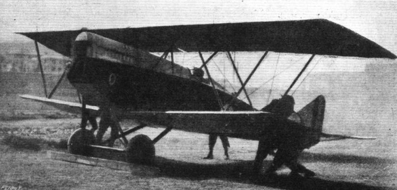
Three-quarter front view of the Italian S.V.A. fighting scout.

Front view of the Italian S.V.A. fighting scout (S.V.A.5 Primo Biplane).
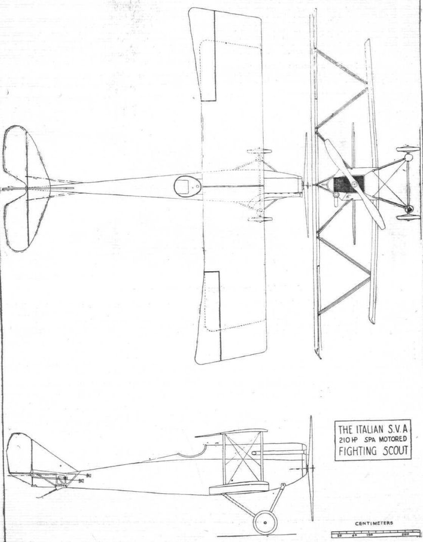
THE ITALIAN S.V.A. FIGHTING SCOUT BIPLANE. - Plan, side and front elevation to scale.

An S.V.A. scout equipped with twin pontoons.
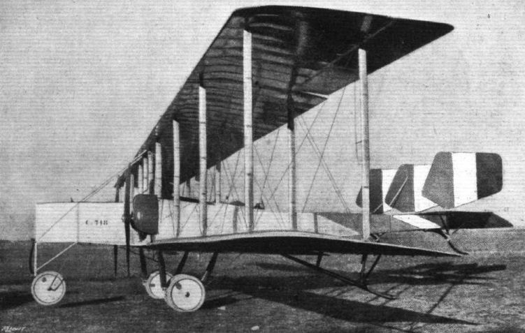
FROM THE SUNNY SOUTH. - One of the Caproni biplanes which are doing such excellent work with our Italian Allies.
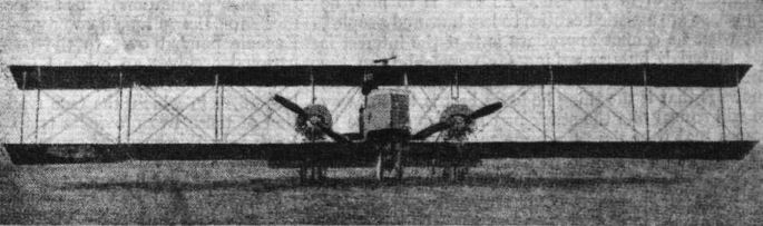
Some aeroplanes of the Fifth Army of France: Caproni.
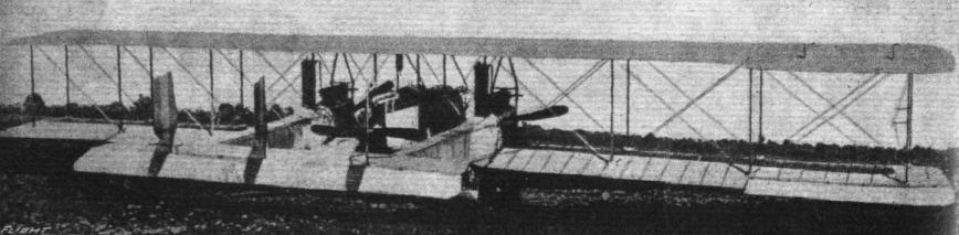
One of the "smaller" Caproni bombing biplanes, fitted with three motors of 200 h.p. each.
Flight, January 24, 1918.
FROM OTHER LANDS.
THE ITALIAN "MACCHI" FIGHTING FLYING BOAT.
THE Macchi single-seater fighting aeroplane is one of the most efficient flying boats ever built. Owing to the fineness of its construction, its light weight, and high-powered motor, it is able to ascend to an altitude of 13,000 ft. in only 18 minutes. In a single-seater fighting machine quick climb is, of course, one of the most important essentials of performance, although this adaptability to climbing rapidly is not generally associated with machines of the flying boat class.
Head resistance has been reduced to a minimum, especially in regard to interplane bracing. The struts and interplane bracing is similar in principle to that employed in the French Nieuport scout - the single pair of V-struts, the narrow lower plane, and the outline of the planes themselves bear a resemblance to the Nieuport. The Macchi is provided with steel tube overhung braces, because of the area extending beyond the interplane struts.
The overall dimensions of the machine are: Span 39 ft. 4 7/16 ins.; overall length, 27 ft. 3 ins.; overall height 9 ft. 10 1/16 ins. There is a lifting surface of 301 square ft and the loading per square ft. is 6.85 lbs. When empty the machine weighs 1,510 lbs. When fully loaded to its gross weight of 2,060 lbs., the military weight is distributed as follows: Petrol and lubricating oil, 265 lbs.; pilot, 175 lbs; two Fiat machine guns, both firing forward, 110 lbs. Total weight of useful load carried, 550 lbs. Near the surface of the water the machine can travel at a rate of 112 m.p.h. In the first four minutes it can climb to 3,250 ft.; eight minutes, 6,500 ft. twelve and one half minutes, 10,000 ft. Sufficient petrol and oil is carried for an air endurance of three hours.
The Isotta-Fraschini engine, with which the Macchi boat is equipped, is known as the V4B. This is a six-cylinder vertical type with nominal h.p. of 150 and a bench-test normal h.p. of 190 at 1,400 r.p.m. Bore, 5.2 ins; stroke, 7.1 ins. Overall dimensions of the V4B - length, 5 ft 5/16 ins.; height 3 ft. 3 1/8 ins.; width, 2 ft. 3 15/16 ins. Carburettors, Zenith; magnetos, Marelli. The weight of the engine complete, dry, is 573 lbs. Its weight per b.h.p. is 3.01 lbs.
Petrol is consumed at the rate of 8.82 oz per hour; oil consumption per b.h.p., 7 oz.
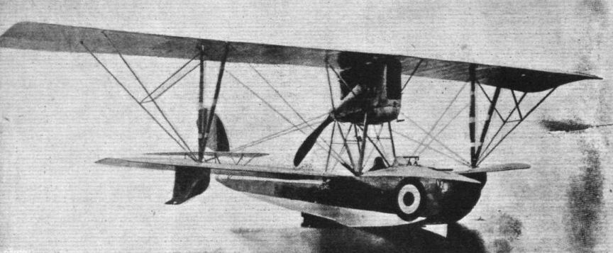
The Italian " Macchi" flying boat, equipped with a 200 h.p. engine.
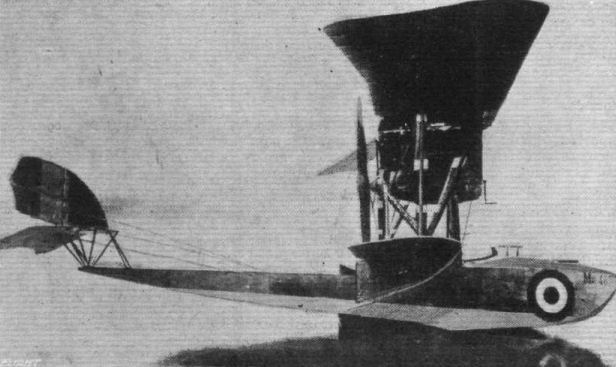
Side view of the Italian "Macchi" flying boat.
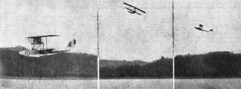
Three views of the Italian "Macchi" flying boat in flight. Note the steep climbing angle in the right-hand view.

WAR LOAN WEEK IN TRAFALGAR SQUARE. - The Italian S.I.A. biplane, in which Capt. the Marquis Laureati made his Turin-London non-stop flight, with a nearer view of its engine and the extra petrol tank.
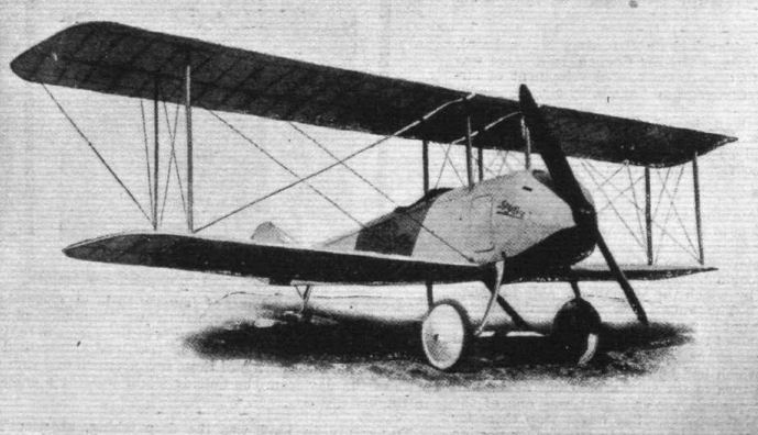
A Dutch Aeroplane. - A military tractor scout produced by the well-known Spyker motor car firm at Trompenburg, Amsterdam.
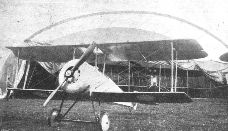
THE SIKORSKY SCOUT. - Three-quarter front view of this machine fitted with 110 h.p. Le Rhone engine.
An S-20 shown at the front in late 1916 Directly behind the S-20 is a large portable cloth hangar; extending out is the nose of an Il'ya Muromets bomber (type "V").
An S-20 shown at the front in late 1916 Directly behind the S-20 is a large portable cloth hangar; extending out is the nose of an Il'ya Muromets bomber (type "V").
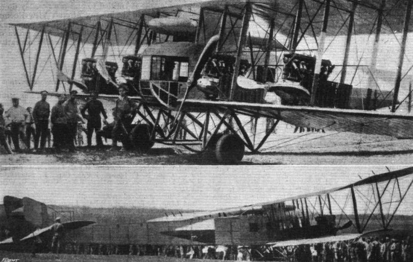
One of the Four-engined Sikorsky Ilya Mourometz heavy bombers that served so well from 1915. Type B used four Salmson-Canton-Unne radials of 200 h.p. (two each), weighed 10,580 lb, could carry 1,102 lb of bombs, and flew at 60 miles per hour.
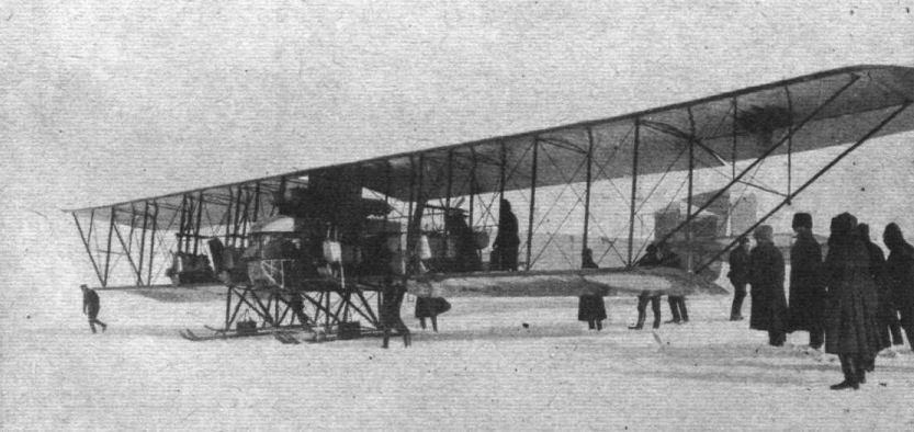
A Sikorsky biplane fitted with snow skids for winter flying.
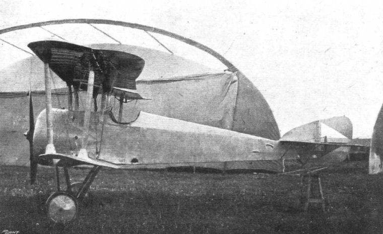
The prototype single seat Sikorsky S.20, serial no 267, is seen here with the insignia of the Imperial Russian Air Service on its rudder. Designed at the close of 1916, the S.20 was the victim of double misfortune in being underpowered and emerging just a few short months before Russia was to sue for peace as part of its political collapse in the spring of 1917. Two S.20s were built, the first using an 80hp Le Rhone, while the second machine had a 110hp Le Rhone. Top level speed of the higher powered S.20 was cited at 118mph, while it took 6 minutes 20 seconds to reach 6,540 feet. Its armament was to have been a single .303-inch Vickers, putting it at a disadvantage compared with contemporary foes.
Although the S-20 was successful, production was terminated so Sikorsky could concentrate on production of the Il'ya Muromets bombers.
Although the S-20 was successful, production was terminated so Sikorsky could concentrate on production of the Il'ya Muromets bombers.
THE SIKORSKY SCOUT. - Three-quarter front view of this machine fitted with 110 h.p. Le Rhone engine.
An S-20 shown at the front in late 1916 Directly behind the S-20 is a large portable cloth hangar; extending out is the nose of an Il'ya Muromets bomber (type "V").
An S-20 shown at the front in late 1916 Directly behind the S-20 is a large portable cloth hangar; extending out is the nose of an Il'ya Muromets bomber (type "V").
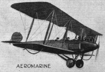
American aeroplane types of 1917-18: Aeromarine.
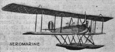
American aeroplane types of 1917-18: Aeromarine.
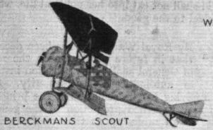
American aeroplane types of 1917-18: Berckmans Scout.

American aeroplane types of 1917-18: Breese "Penguin".

American aeroplane types of 1917-18: Burgess "B.P." Tractor.

American aeroplane types of 1917-18: Burgess "HT-2" Scout Hydro.
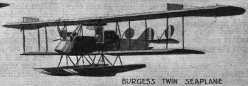
American aeroplane types of 1917-18: Burgess Twin Seaplane.
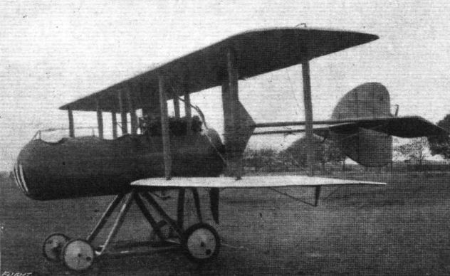
A speedy American pusher biplane, built by the Continental Co., having a speed of about 95 m.p.h. It is fitted with a 135 h.p. Hall-Scott motor.
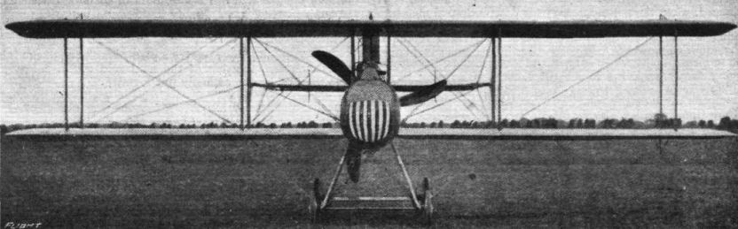
A front view of the American Continental pusher biplane, which is fitted with a 135 h.p. Hall-Scott motor, and has a speed of about 95 m.p.h.

American aeroplane types of 1917-18: Continental Pusher.
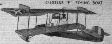
American aeroplane types of 1917-18: Curtiss "F" Flying Boat.
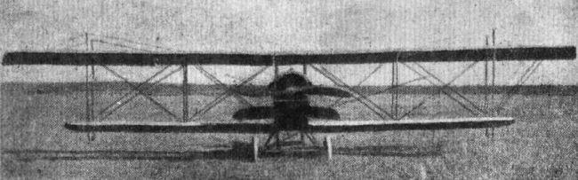
Some aeroplanes of the Fifth Army of France: Curtiss (training).
Flight, January 17, 1918.
AN AUSTRALIAN RECORD FLIGHT.
SOME very fine performances were put up in Australia in November last by Lieut. W. J. Stutt, who will be remembered by our readers as a Bristol pilot previous to the war, and is now at the State Aviation School. On his Curtiss biplane, he flew from the Richmond school near Sydney, N.S.W., to Point Cook near Melbourne, Victoria, covering the journey of 600 miles in 9 hours 32 minutes, his best non-stop being 263 miles in 3 hours 37 minutes. He improved on this considerably on the return journey, for which his total time was 7 hours 20 minutes. He had one stop of 1 hour 17 minutes at Cootamundra - and his best non-stop run was 342 miles in 4 hours 10 minutes, averaging 82 miles an hour. This is a record for Australia. Lieut. Stutt is the first aviator to fly between Melbourne and Sydney in one day. During the return journey he encountered very bad weather, and after passing Goulburn was driven out to sea by a rainstorm. A passenger was carried during the first part of the journey, but Lieut. Stutt flew alone for the concluding stage, as the engine was not running at its best. Point Cook was left at 5.53 a.m., Cootamundra reached at 10.3 a.m., and left at 11.20, the machine finally landing at Richmond at 2.30 p.m.
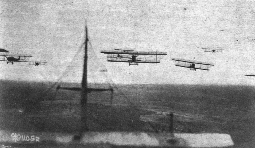
WITH THE AMERICAN ARMY AVIATION SECTION. - Cross-country formation flying, snapped from one of the aeroplanes by the official photographer. Eleven aeroplanes are, in all, in evidence In this photograph.

WITH THE AMERICAN FLYING SECTION. - A couple of pictures taken in the air of formation and cross-country flying at Kelly Field, San Antonio, Texas.

Lieut. W. J Stutt at the wheel of his Curtiss machine in which he made his record flight in Australia.
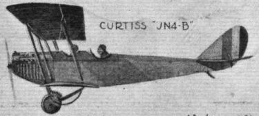
American aeroplane types of 1917-18: Curtiss "JN-4B".
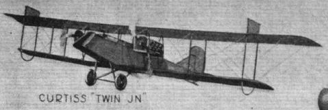
American aeroplane types of 1917-18: Curtiss "Twin JN".
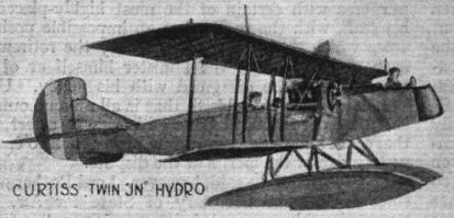
American aeroplane types of 1917-18: Curtiss Twin "JN" Hydro.
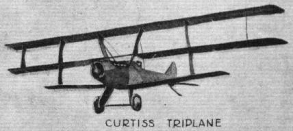
American aeroplane types of 1917-18: Curtiss Triplane.

American aeroplane types of 1917-18: Curtiss H12 Flying Boat.
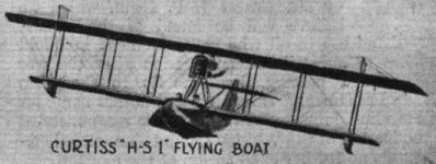
American aeroplane types of 1917-18: Curtiss "H-S 1" Flying Boat.
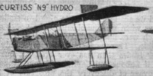
American aeroplane types of 1917-18: Curtiss "N9" Hydro.
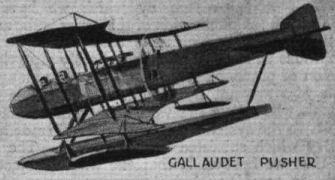
American aeroplane types of 1917-18: Gallaudet Pusher.
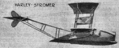
American aeroplane types of 1917-18: Harley-Stromer.
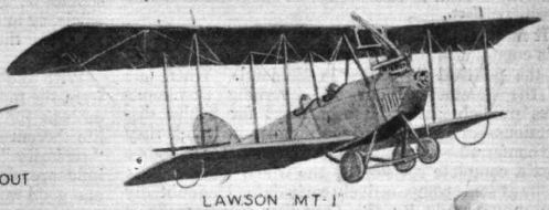
American aeroplane types of 1917-18: Lawson "MT-1".
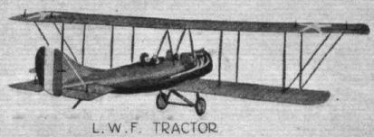
American aeroplane types of 1917-18: L.W.F. Tractor.

American aeroplane types of 1917-18: Wright-Martin "S".
The latest production of Captain Jas. V. Martin, who will be remembered for his flying at Hendon previous to the War, and who for some years has been at work in the U.S.A. The machine includes several novel features: a folding chassis, K bar cellule truss, wing end ailerons, shock-absorber rudder, and a rubber hinge closing the gap between the fuselage and the rudder.
American aeroplane types of 1917-18: Ordnance Engineering.
American aeroplane types of 1917-18: Pierce Sport Tractor.
American aeroplane types of 1917-18: Standard "J-R" Pursuit.
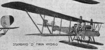
American aeroplane types of 1917-18: Standard "D" Twin Hydro.
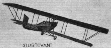
American aeroplane types of 1917-18: Sturtrevant.
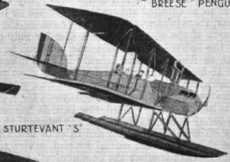
American aeroplane types of 1917-18: Sturtrevant "S".
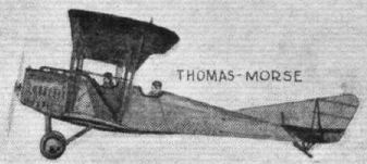
American aeroplane types of 1917-18: Thomas-Morse.

American aeroplane types of 1917-18: Thomas-Morse Seaplane.
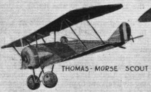
American aeroplane types of 1917-18: Thomas-Morse Scout.
Flight, January 31, 1918.
THE UNITED EASTERN TRACTOR BIPLANE.
DURING the latter part of 1917, the United Eastern Aeroplane Corporation of Brooklyn, N.Y., U.S.A., turned out several very successful training tractor biplanes, a description of which, together with illustrations and scale drawings, we give herewith. The Eastern tractor has been designed strictly to Government specifications, and is, we are informed, specially noteworthy as regards workmanship and finish.
The main planes are built up in five sections, two being attached to a smaller central section or panel, supported above the fuselage by four struts, comprising the top surface, and two attached direct to the fuselage, forming the lower surface. Eiffel No. 36 wing-section has been selected on account of the high L/D ratio, giving quick climb and high loading at comparatively slow speed. The planes are given a dihedral angle of 1° and the top plane is staggered forward about 4 ins. The normal angle of incidence is about 3°. The planes are built up in the conventional manner of spruce, spars and ribs of the lightest possible section. Two pairs of streamlined struts separate top and bottom planes on each side of the fuselage. The bracing is of Roebling steel cable doubled in the centre sections. Drift wires are taken from the forward ends of the upper fuselage longerons to the top of the front inner interplane struts, and from the forward ends of the lower longerons to the lower ends of the same interplane struts. The outer portions of the top plane extending beyond the interplane struts are braced from kingposts above these struts. Lateral control is obtained by means of a pair of interconnected ailerons, each 16 sq. ft. area, hinged to the top plane rear spar. The chord of these ailerons increases towards the tips, where the trailing edge is given a slight up-turn.
The horizontal stabilising plane, 36 sq. ft. area, is of one piece construction, with raked ends and rounded corners. It is of the flat cambered, non-lifting type, and is mounted on the top longerons of the fuselage. The elevator is divided into two flaps, with the rudder working in between, and is constructed of steel tubing with wood ribs. The rudder, which is of distinctive shape, is partly balanced by a small surface forward of the pivoting post, and has an area of 15 sq. ft. The controlling surfaces are operated by standard dual stick and rudder-bar control.
The fuselage is of standard construction; wooden members and metal fittings, braced with piano wire and Roebling cable, doubled at the forward section. It is built up in two sections, being joined immediately behind the rear cockpit. It is rectangular in section, tapering to a vertical knife-edge at the rear, having a maximum width and depth of 2 ft. 3 ins. and 3 ft., respectively. The forward portion, enclosing the engine, and the top turtle deck as far back as the rear cockpit is covered with sheet aluminium, the remainder of the fuselage being fabric covered. The cockpits are made as comfortable as possible, being well upholstered.
A two-wheel type landing gear is fitted, the wheels being 26 x 4 ins. The axle, which is of 1 3/4 in. chrome nickel steel, is mounted by means of rubber shock absorbers on a pair of laminated ash hockey-club shaped skids. A vertical strut both fore and aft of the axle on each skid connect the latter with the fuselage. The two forward chassis struts are connected by a horizontal tie rod, and the chassis is cross wire braced at this point. The wheel track is 5 ft. 3 ins. Rattan hoop-skids are mounted on the lower wing tips, just below the outer interplane struts, and a swiveling skid is located under the tail.
The power plant consists of a Curtiss 90 h.p. OX-5 8-cyl. V, coupled direct to an 8 ft. 3 ins. tractor screw. Mounted in the nose of the fuselage, immediately in front of the engine, is the radiator weighing 55 lbs. There are two petrol tanks, a small gravity tank of 5 gals, capacity located under the engine cowling, and a main tank containing 30 galls, under the front seat.
The gravity tank is fed by pressure obtained from an air pump worked by the motor. A hand pump is also provided.
The principal characteristics of the Eastern tractor are: span, upper 41 ft., lower 32 ft. 7 ins.; chord, 5 ft. 3 ins. ; gap 5 ft. 6 1/2 ins.; stagger, 4 ins.; dihedral, 1°; angle of incidence, 3°; wing section, Eiffel 36; overall length, 27 ft.; overall height, 10 ft. 6 ins.; total area of main planes, 390 sq. ft.; speed range (full load), 40-75 m.p.h.; climb, 4,000 ft. in 10 mins.; gliding angle, 1 in 7.
----
Janes, 1919.
Span 39'
Chord 5'6''
Gap 6'
Length 25'6''
Dihedral 1
Sweep back 8
Stagger 9
Area 350 sq. ft.
Ailerons Upper planes
Landing gear 2 wheels
Engine Curtiss 100 h.p. (OXX.2)
Weight with one hour's fuel 1200 lbs.
Useful load 800 lbs.

Side view of the United Eastern training tractor biplane.

The fore part of the United Eastern training tractor biplane, showing the 90 h.p. Curtiss engine and the landing chassis.

American aeroplane types of 1917-18: United Eastern.
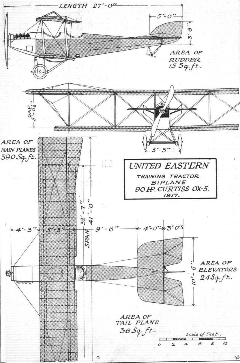

American aeroplane types of 1917-18: Wittemann-Lewis.

American aeroplane types of 1917-18: Wright-Martin "V".

American aeroplane types of 1917-18: Wright-Martin "R".
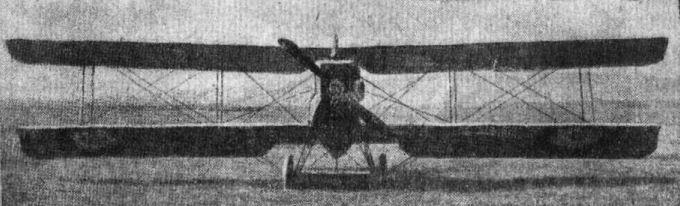
Some aeroplanes of the Fifth Army of France: Breguet A V.
Flight, September 19, 1918.
THE FRENCH A.R. BIPLANE,
WITH 190 H.P. RENAULT MOTOR.
[The following illustrated description of the French "A.R." machine has been translated from a German contemporary, and should be of considerable interest, inasmuch as one is not permitted to refer in detail to the modern aeroplanes of the Allies until the enemy has issued a report. - ED.]
THIS machine, designed by Dorand, is designated as A.R., or A.L.D., according to whether it is fitted with a Renault or with a Lorraine-Dietrich engine. The particular machine under review is marked A.R., Type 1, and the number is 309. The machine is a two-strutter biplane of 13.30 m. span, and has its fuselage supported between the planes on ash struts. Sweep-back and dihedral angle are only present in the lower plane. The former amounts to 1 deg., while the dihedral angle is 2 deg. The top plane is staggered backwards 0.5 m. The gap is 1.825 and 2 m. respectively, that is to say in the centre it is 0.945 of the chord. The angle of incidence of the upper plane is 2.5 deg., that of the lower plane 3 deg.
The halves of the wings are screwed together in the centre of the machine. The wing spars appear to be of I section, covered on both sides with three-ply. Between every two ribs, whose spacing is 300 to 340 mm., is a short false rib on the top surface only, running from the leading edge to the front spar. The wing fabric, which is of a cream colour, is sewn to the ribs. In front of the trailing edge, which is formed by a wire, as in all French machines, eyelets are incorporated.
The plane struts, which, with the exception of those secured to the body, are of hollow section, are of stream-line form. In order to prevent lateral bending the outer plane-struts are provided with a peculiar bracing. In addition the middle of the struts are braced to one another and to the bottom of the body struts. (See illustrations.) The strut fittings are of a very simple type, as shown in one of the illustrations. Strut sockets of sheet steel are secured -to the spars by U bolts, the two shanks of which pass through the spar and are secured by nuts on the other side. The flying wires and landing wires are anchored to the corners of these U bolts, while the incidence wires are secured to lugs projecting from and forming part of the steel plate bottom of the strut sockets. This bottom is simply resting inside the socket and is not secured in any other way.
The wing bracing consists of solid wires throughout, which are connected to the fittings and turnbuckles in the usual way by bending them over and sliding a ferrule of spiral wire over the free end. The flying wires are in duplicate and lie one behind the other. The space between them is filled with a strip of wood. The external drift wire running to the nose of the body is wrapped with thin cord to prevent it becoming entangled in the propeller in case of breakage. Between the fuselage and the lower plane there is diagonal bracing in the plane of each spar. As. however, there is no corresponding bracing above the fuselage, the upper ends of the top plane body struts are allowed a considerable amount of play.
Non-balanced ailerons, positively operated, are hinged direct to the rear spar of the top plane only. The aileron control cables are in the form of simple cables running from the sprocket wheel on the control column, around pulleys in the lower plane, along the lower side of the lower plane and under another pair of pulleys. From this point on they are in the form of solid wires of 2 mm. diameter running to the aileron crank levers, which are in the form of quadrants. The upper cranks of the ailerons are connected by cables and wires running across from side to side, along the upper surface of the top plane.
At the stern of the fuselage is fixed a small tail plane to which is pivotted the balanced trapezoidal elevator. The rudder is also balanced. The rudder post is braced to the elevator, and this in turn to the body, by stream-line steel tube struts. The ends of these struts are flattened oat and bolted to the various fittings. There is no vertical fin. The rudder is controlled by plain wires of 2.5 mm. diameter. Only where they pass over pulleys have cables been substituted for the wire's.
The undercarriage struts are secured to the spars of the lower plane at the points where occur the attachments for the struts running to the body. The short body struts are braced by stream-line tubes fore and aft to the body. The one-piece axle rests between two cross struts of steel, tube. The travel of the axle is not restricted. The undercarriage is braced diagonally in the plane of both pairs of struts.
The longerons and struts of the fuselage, which is fabric covered, are made of ash up to the observer's seat. From there they are made of spruce. The struts of the rear poition of the fuselage rest on the longerons without any attachment, and are held in place by the bracing only. To prevent them from sliding along the longerons the ends of the struts are notched to correspond with the shape of the wiring lugs, which surround the longerons. (See illustration.)
The 8-cylinder, Vee type Renault motor develops, according to a plate in the pilot's cockpit, 190 h.p. at 1,550 to 1,600 r.p.m. The radiator is placed between the body and the lower plane. There is a shutter arrangement for varying the cooling. A water collector or tank is placed above the port row of cylinders. The exhaust gases are carried outwards to each side through short collectors. With the older motors the exhaust from both rows of cylinders was carried inwards to a common collector carrying it up above the top plane, an arrangement which greatly hampered the view of the pilot. In these machines the radiator was in the nose of the body. An auxiliary radiator was placed below the fuselage.
The motor is bolted to two channel section steel bearers, which rest on strong sheet steel cradles. Immediately behind the engine is placed transversely the oil tank, which has a capacity of 7 litres. The main petrol tank, which has a capacity of 170 litres, is divided into three compartments, and is placed behind the pilot's seat. From here the petrol is pumped into a small gravity tank holding 12 litres and placed behind the engine. For this is employed either a pump driven by the engine or a hand pump to the right of the pilot. If too much petrol is pumped through it is returned to the main tank via an overflow.
The pilot sits in a line with the leading edge of the top plane. Here he has a very good view forward, but the view in a rearward and upward direction is very restricted.
On the instrument board in front of the pilot are the following instruments: A cooling water thermometer, ignition control, compass, petrol cock and revolutions indicator. To the right, at the side of the seat, is the petrol hand pump with a three-way cock as well as the trimming gear for the elevator. On the left are the levers for advancing or retarding the ignition, the petrol and air levers, the radiator shutter control and the oil cock. In the floor of the fuselage, in front of the rudder bar, there are small windows.
In the observer's cockpit there are two folding seats, one in front and one at the rear. In front, behind the petrol tank, there are on each side racks for four bombs. Between these racks, through an opening in the floor, the photographic camera can be inserted. A shelf for plate holders is placed behind the port bomb racks. On the starboard inner wall of the observer's seat are aluminium plates for the switches and keys of the wireless. The other instruments of the wireless are placed aft of the seat.
The pilot is armed with a fixed machine gun placed on the right hand side above the body, and is operated from the left cam shaft. Firing is accomplished by Bowden control from the control wheel. The observer has two movable machine guns, coupled together and mounted on a gun ring with elevating arrangements.
The weight of the machine, empty, was ascertained to be 890 kg. An inscription on the rudder states that the weight of the fuel (poids combustible) is 140 kg., and that the useful load (poids utile) is 300 kg. This gives a total weight of 1,330 kg. As the area is 50.36 sq. m. the loading is 1,330 : 50.36 = 26.40 kg./sq. m. The loading per h.p. is 1,330 : 190-36 = 7.0 kg./h.p.
The chief aim of the designer appears to have been to provide a light machine with low wing loading. The construction of the details such as fittings, wiring, lugs, &c. has therefore been kept very light and simple.
Item weights. - Motor, 245 kg.; cooling water, 25 kg.; air screw, 22 kg.; one petrol main tank, 22.5 kg.; one petrol gravity tank, 2 kg.; one oil tank, 2 kg.; motor-accessories, exhaust collector, body, &c, 244.5 kg.; undercarriage, 60 kg.; controls, 6 kg.; wings, 234.5 kg.; bracing, 26.5 kg.; weight empty, 890 kg.; total weight, 1,330 kg.
Loads. - Pilot and observer, 150 kg.; armament, 75 kg.; four bombs at 12 kg., 48 kg.; wireless and camera, 27 kg.; 182 litres petrol and 7 litres oil, 140 kg.; total, 440 kg.
Weight of wings. - 4.65 kg./sq. m.
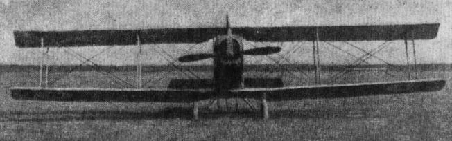
Some aeroplanes of the Fifth Army of France: AR (Dorand).
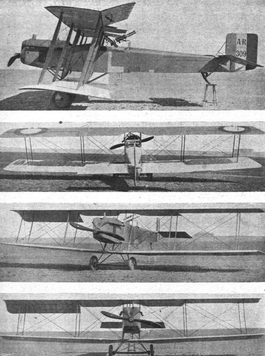
Four views of the French, A.R. biplane.
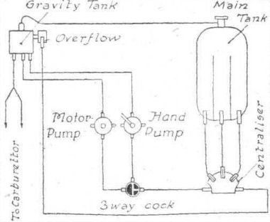
Petrol system of the A.R. biplane.

Plan and elevation of the body of the French A.R. biplane.
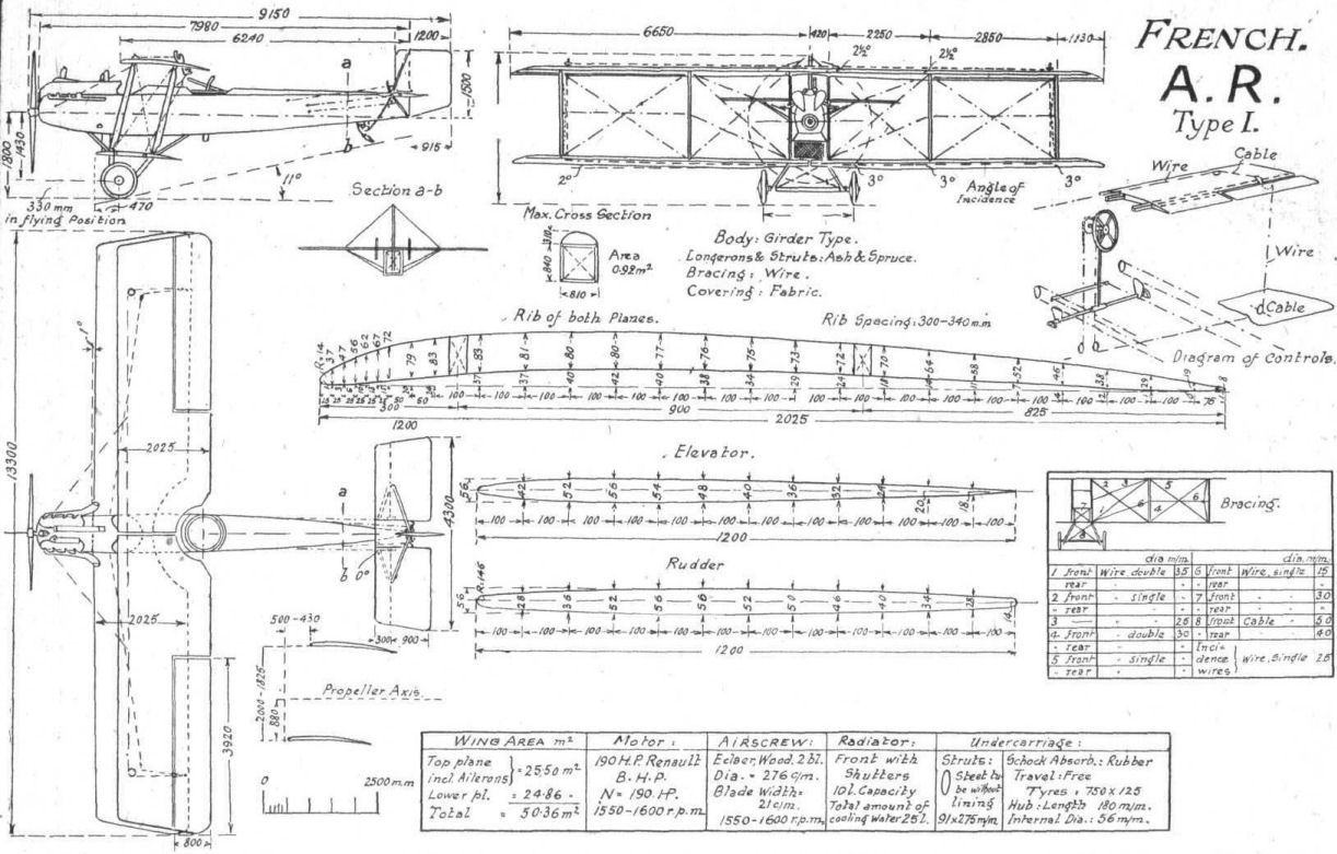
General arrangement, and some details, of the French A.R. biplane.

Some aeroplanes of the Fifth Army of France: Farman F.90.
Flight, April 11, 1918.
FROM OTHER LANDS.
THE F.B.A. FLYING BOAT.
WE are indebted to our American contemporary Aerial Age for the accompanying illustrations and scale drawings (passed by the U.S. censor) of the F.B.A. Flying Boat, which has been used with such great success by the Allies for over-water scouting and fighting.
The Franco-British Aviation (Societe Anonyme), Paris, was founded in 1914 by Lieut. Jean de Conneau, (Andre Beaumont, winner of the Paris-Rome, Circuit-European, and Circuit-of-Britain races), and M. Schraeck of the French Wright Co., to exploit the patents pertaining to the Donnet-Leveque and Artois Flying Boats.
During the war various models of F.B.A. boats have been produced and employed by the Allies, more particularly France and Italy, and these machines, equipped with Gnome, Clerget, or more often Hispano-Suiza engines, have proved very efficient and speedy. The accompanying illustrations and scale drawings show the model fitted with the 130 h.p. Hispano-Suiza as used by the French. The top plane has a span of about 46 ft. 6 ins., and a chord of 6 ft., whilst the span and chord of the lower plane are 35 ft. and 5 ft. respectively. The gap between the planes is 5 ft. 9 ins., and the overall length of the machine is 32 ft. 6 ins.
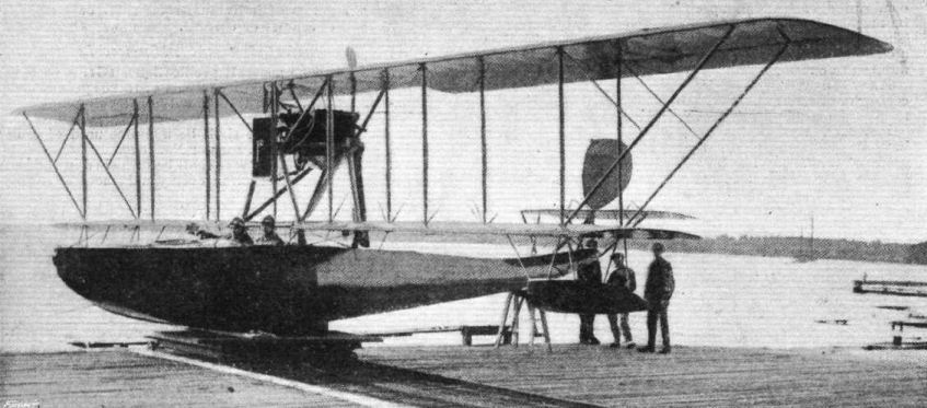
Three-quarter rear view of the Hispano-Suiza-motored F.B.A. flying boat.
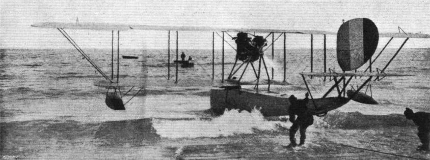
View from the rear of the Hispano-Suiza-motored F.B.A. flying boat.
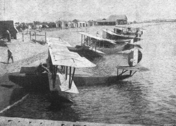
French seaplanes ready for patrol work at a French Seaplane Station on the Mediterranean coast.
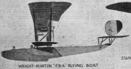
American aeroplane types of 1917-18: Wright-Martin "F.B.A." Flying Boat.

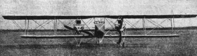
Some aeroplanes of the Fifth Army of France: Letord.
THE LONG AND THE SHORT OF IT. - A Handley-Page bomber and a Nieuport single-seater are objects for Hun curiosity.
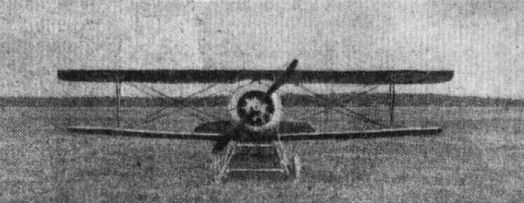
Some aeroplanes of the Fifth Army of France: Nieuport.
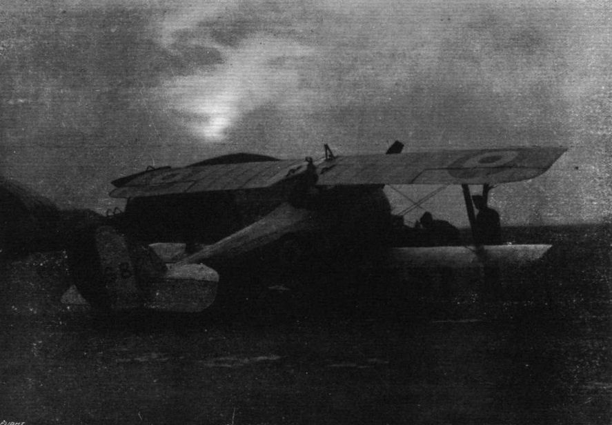
A Scout aeroplane on the British Western Front being prepared for a moonlight flight.

ON THE BRITISH WESTERN FRONT. - A British scouting squadron. Aeroplanes lined up ready to fly over the enemy lines.
A well-known photograph of the Nieuports of No.l Squadron, RFC, in the snow at Bailleul on December 27 1917. This is a mixed assembly of Nie.24bis and Nie.27; unfortunately, the wartime censor had obliterated the serial numbers of the aircraft. The nearest is a Nie.27 that has an oddly dark-coloured lower wing, perhaps a replacement on an otherwise aluminium-painted aircraft. The second in the line, a Nie.24bis, has what appears to be a camera gun on the overwing mounting.
A well-known photograph of the Nieuports of No.l Squadron, RFC, in the snow at Bailleul on December 27 1917. This is a mixed assembly of Nie.24bis and Nie.27; unfortunately, the wartime censor had obliterated the serial numbers of the aircraft. The nearest is a Nie.27 that has an oddly dark-coloured lower wing, perhaps a replacement on an otherwise aluminium-painted aircraft. The second in the line, a Nie.24bis, has what appears to be a camera gun on the overwing mounting.
A bombing machine on the British western front in France tucking its eggs under its wings prior to a daylight trip, with one of its attendant fighting scouts in waiting.
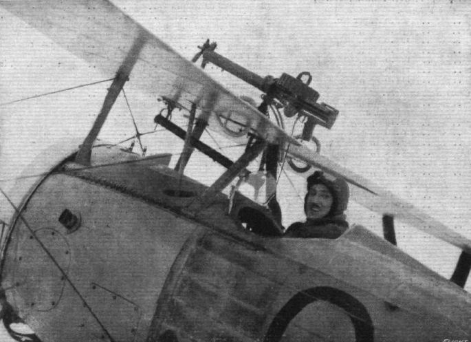
On the British Western Front in France. A Gotha strafer, who recently brought down a Gotha aeroplane.
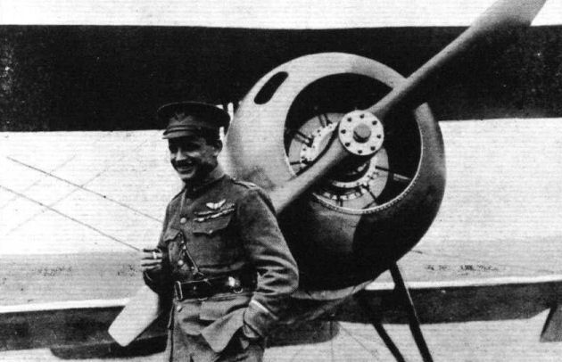
Major Raoul Lufberry, the American "Ace" of the American Expeditionary Force in France, who was shot down on May 19th at the American front, and his plane.
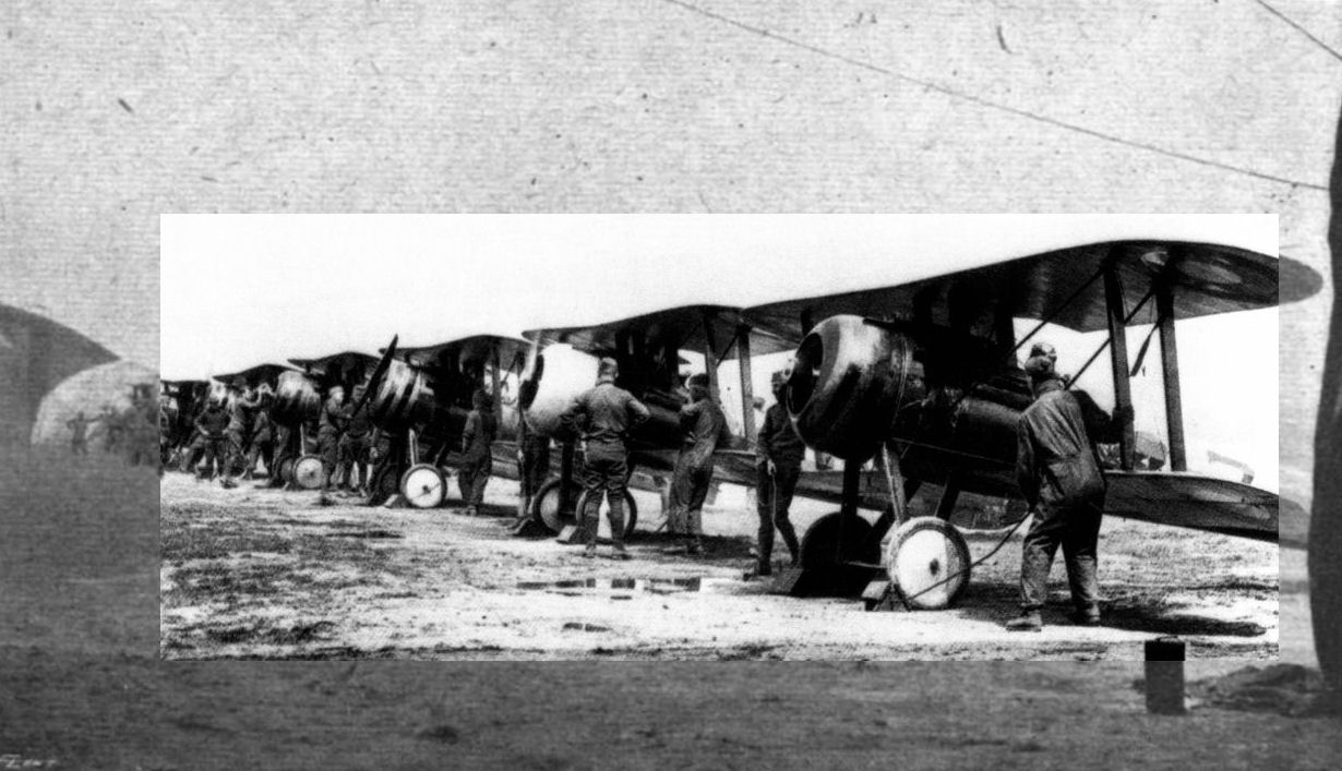
Предполетная проверка двигателей на "ньюпорах-28" 95-го американского дивизиона, Франция, 1918 г.
WITH THE U.S. ARMY. - Waiting for an "Alert."
WITH THE U.S. ARMY. - Waiting for an "Alert."
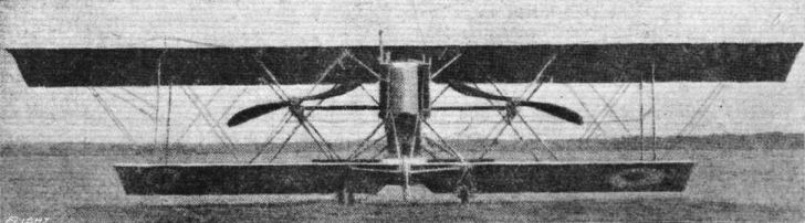
Some aeroplanes of the Fifth Army of France: Moineau.
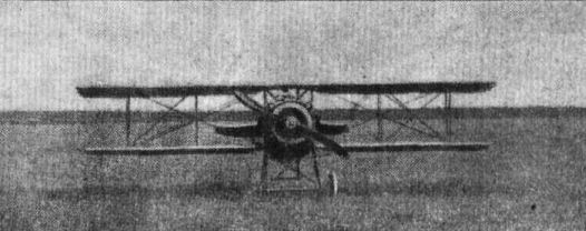
Some aeroplanes of the Fifth Army of France: SPAD.
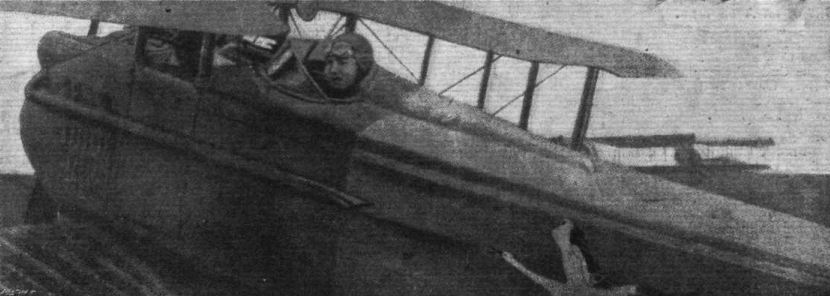
Lieutenant Fonck, the very successful French pilot, in one of the machines which have helped him to do such execution.
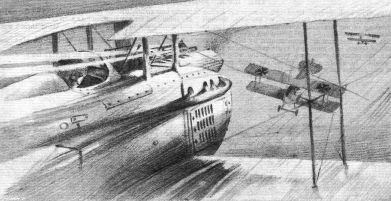
"I turned quickly and let the nearest one have a handful of lead, which seemed to deter him somewhat, for he dived away East."
Flight, May 16, 1918.
THE SPAD TWO-SEATER.
200 H.P. HISPANO-SUIZA ENGINE.
THE following particulars and illustrations, apparently from an official report on the Spad two-seater, are published in Flugsport of April 10th :-
The Spad two-seater, which is shown in the accompanying illustrations, is marked B 6006, and is built under licence in July, 1917, by the Aircraft Works of Ad. Bernard in La Courneuve (Seine). In general design and in constructional details it resembles the single-seaters, but does not have the divided inner interplane struts usually found on these. It is built as an ordinary two-strutter. The spars of the lower wings are braced to the under-carriage from the point of attachment of the inner pair of struts. The upper wing, which runs right through, has a span of 11.22 metres, and a chord of 1.53 metres, while the lower wing has a span of 10.90 metres and a chord of 1.43 metres. The gap is 1.335 metres and the stagger 0.4 metre. There is no dihedral angle, but both upper and lower wings are swept back, the angle being 174°. In order to give a better view, the lower wings have been cut away near the body, and the upper wing has a cut-out portion in the centre. The two spars are placed closer together than those of the lower wing, and the interplane struts converge somewhat upwards. The angle of incidence of the upper plane is 2.8° in the centre, and 2.5° at the tip, while the lower plane has a uniform angle of 1.5°. The lift wires are in duplicate, and in order to reduce head resistance, the space between them is filled up with strips of wood. The landing wires are single. A drift cable runs, from the junction of the inner interplane strut to the upper front spar, to the point of attachment of the front under-carriage strut. The interplane struts, which are of streamline section, are made of wood. Their fittings are attached to a steel tube carried inside the strut.
The spacing of the ribs is 190 mm. in the top wing and 175 mm. in the lower wing. Between the ribs there are false ribs on the upper surface running from leading edge to front spar. The fabric is tacked to some more strongly constructed ribs, and is, in addition, stitched to ribs and to the wire forming the trailing edge. On the under surface, near the trailing edge, there are eyelets which serve to equalise the pressure and to drain any moisture out of the wing. Wing and body covering are painted a yellowish white.
Non-balanced ailerons are hinged to false spars in the upper plane. They are operated by means of pull and push rods which rest in the lower plane behind the rear spars, and the movement of which is transmitted through cranks at the lower ends of the outer struts, to vertical struts pivotted to the lower surface of the aileron.
The body, which is of the usual construction, with four longerons, is rounded off top and bottom by formers and stringers. The longerons have a rectangular section, while the vertical and horizontal body struts are spindled out to an I section, and are reinforced by plywood. A trap-door in the floor behind the observer's cockpit provides access to the interior of the body.
The stabilising and control surfaces are of the usual Spad type. The tail plane, which runs right across the body, and has both sides cambered, is attached to the upper longeron at an angle of incidence of 0°. To its trailing edge, the divided elevator is hinged by means of a steel tube. In order to reduce resistance, the cranks are placed in the centre inside the body and vertical fin.
The machine is provided with dual control. For operating the ailerons, the movement of the control shaft is transmitted by means of a lever, to a rocker supported in a partition between pilot's and observer's cockpits. The rods - which rest in the bottom wing - engage with a downward projection of this rocker. The observer's control lever is in the form of a telescopic tube, whose upper part is forced upwards by a spiral spring, or pressed down when not in use, and held in position by a bayonet joint. When extended, its length measured from the pivotting point is 53 centimetres, and when telescoped it measures 36 centimetres. The rudder bar in the observer's cockpit can be covered over with detachable covers, to guard against accidental use. The V form under-carriage struts are made up of several layers of wood glued together, and the whole covered with fabric. Diagonal bracing is employed in both front and rear bays. The two stub axles rest between two cross tubes covered with fabric, and move in slots in the struts. The travel is 125 mm. The VEE type Hispano-Suiza engine, which develops about 200 h.p. at 2,000 r.p.m., rests on engine bearers which are connected up to the body longerons by means of transverse supports of three-ply wood, and angle pieces pressed out of aluminium. The two-bladed air screw is geared down, by means of gearing incorporated with the engine in the ratio 4:3. The exhaust gases are carried away by collectors on each side of the body extending to behind the pilot's seat.
A pressure petrol tank with a capacity of 140 litres forms the pilot's seat, while a gravity tank holding 10 litres is mounted in the upper wing, between the spars. The oil tank, which holds 15 litres, rests on the floor of the body behind the engine. The bottom of the oil tank has pressed on it ribs for cooling the oil. The fuel capacity is sufficient for a flight of about 2 hours' duration.
The radiator, which is provided with shutters, forms the nose of the fuselage. A reservoir connected with the radiator is built into the upper wing in front of the front spar. Any steam or excess water is carried off underneath the body by means of an overflow and a pipe.
The pilot's seat, which as in all Spad aeroplanes is kept very narrow, is separated from the engine by a linen curtain. In front of it is a wind screen divided into three parts and framed in aluminium.
Of instruments, &c, there are as follows:
On the right: The starter and the hand operated air pump. In the centre: Two switches, one three-way cock for pressure tank and connecting up with either hand or motor air pump, one three-way cock handle for turning on or off the petrol from tank to carburettor, one tap for turning the motor air pump off from the pressure tank, one manometer, and the revs, indicator.
On the left: The gas lever, lever for regulating the mixture, and lever for operating the radiator shutters. There is no provision made for advancing or retarding the magneto. The instruments are to a certain extent badly arranged. Thus the revs, indicator is placed with its dial horizontal and so that the pilot sees the figures upside down.
In the observer's seat are, in addition to the dual controls, two switches, one gas lever, and one lever for regulating the mixture, so that, apart from the petrol controls, the observer can look after the engine. Wireless installation is not fitted, although antennae wires are provided in the body.
The armament consists of a fixed Vickers machine gun mounted above the body, for the pilot. The gun is operated by a push-rod from the right hand cam shaft. The trigger is on the control lever. The observer is armed with two Lewis machine guns coupled together. Six ammunition drums can be carried in the observer's cockpit, suitable brackets being provided.
The weight of the machine empty, but including the cooling water, was ascertained to be 765 kg. A notice on the rudder gives they useful load (poids utile) as 255 kg. and the fuel weight (poids combustible) as 120 kg. This gives a total weight of 1,140 kg., so that the weight per sq. m. (the area is 29.8 sq. m.) is 1140/298 = 38.5 kg., and the weight per h.p. is 1140/200 = 5.7 kg.
Item Weights.
Kg.
Motor 225.0
Cooling water 33.0
Wings 167.9
Elevator and rudder 19.9
Body, &c. 319.2
Total 765
Loading.
Kg.
Pilot and observer 170.0
Armament .. 81.5
Instruments, &c. 3.5
Fuel 120.0
Total 375
Unit weight of wings
167.9/29.8 = 5.64 kg./sq. m.
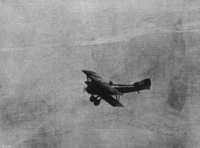
KING ALBERT OF BELGIUM REVIEWS HIS ARMY FROM AN AEROPLANE. - The Royal plane, taken from another plane above it. Below may be seen the Belgian lines, roads, &c., and at the top of the picture the inundations.
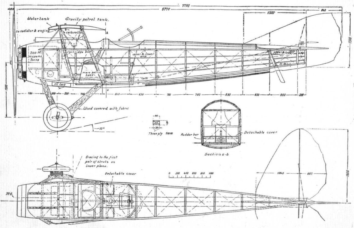
The Spad two-seater, S.XI, 200 h.p. Hispano-Suiza engine.

The Spad two-seater, S.XI, 200 h.p. Hispano-Suiza engine.
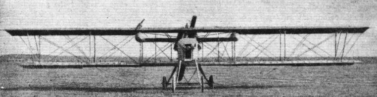
Some aeroplanes of the Fifth Army of France: Voisin.
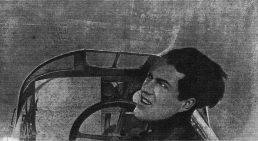
A FRENCH FIGHTER DURING A BOMBARDMENT. - L'Adjutant C - "snapped " by his gunner during flight.
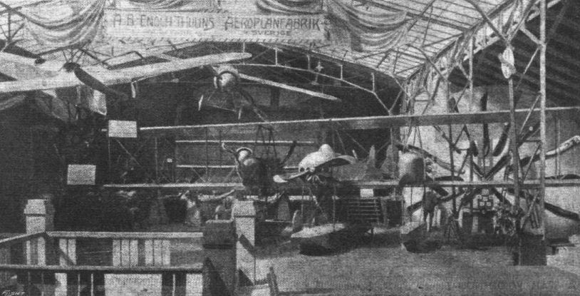
FROM THE CHRISTIANIA AERO SHOW. - The stand of Eloch Thulins Aeroplane Works. On the left is the Bleriot monoplaile on which Lieut. Tryggve Gran crossed the North Sea; hanging from the roof is a sporting monoplane; in the background is seen a biplane single-seater fighter; and in the centre a three-engined seaplane, all built at the Thulin works at Landscrona, Sweden.