
Книги
Putnam
O.Thetford, P.Gray
German Aircraft of the First World War
249
O.Thetford, P.Gray - German Aircraft of the First World War /Putnam/
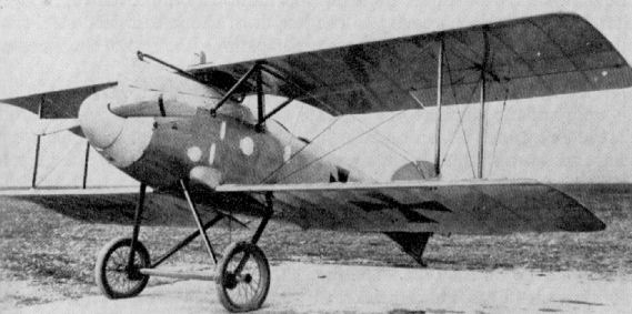
Albatros D II (Austrian-built, with centre-section radiator and Austro-Daimler engine).
A.E.G. B I
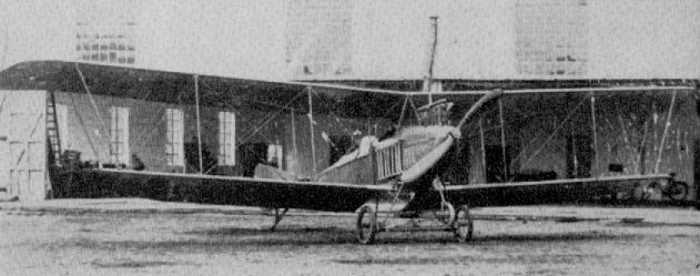
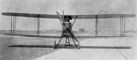
This type of two-seater was used in small numbers for unarmed reconnaissance work during 1914. The tricycle undercarriage is noteworthy. Engine, 100 h.p. Mercedes D I. Span, 15.5 m. (50 ft. 10 1/4 in.). Length, 10.5 m. (34 ft. 5 3/8 in.). Weight empty, 650 kg. (1,430 lb.). Speed, 90/100 km.hr. (56.25 - 62.5 m.p.h.).
This type of two-seater was used in small numbers for unarmed reconnaissance work during 1914. The tricycle undercarriage is noteworthy. Engine, 100 h.p. Mercedes D I. Span, 15.5 m. (50 ft. 10 1/4 in.). Length, 10.5 m. (34 ft. 5 3/8 in.). Weight empty, 650 kg. (1,430 lb.). Speed, 90/100 km.hr. (56.25 - 62.5 m.p.h.).
A.E.G. B I
A.E.G. B II
Powered with a 120 h.p. Mercedes D II engine, this 1914 design was used in small numbers on unarmed reconnaissance duties. This aircraft was the forerunner of the later C I design.
A.E.G. B III
This 1915 development of the B II design was used both for unarmed reconnaissance and as a school machine. Engine, 120 h.p. Mercedes D II. Span, 131 m. (42 ft. 11 3/4 in.). Speed, 110 km.hr. (68.75 m.p.h.).
A.E.G. C I
Introduced in March 1915, the C I was virtually a more powerful B II with a manually operated gun for the observer. The aircraft illustrated is unusual in having a Bergmann machine-gun installed. Engine, 150 h.p. Benz Hz III. Span, 13.07 m. (42 ft. 10 1/2 in.). Length, 7.95 m. (26 ft. 0 7/8 in.). Area, 36 sq.m. (388.8 sq. ft.). Weights: Empty, 710 kg. (1,562 lb.). Loaded, 1,125 kg. (2,475 lb.). Speed, 130 km.hr. (81.25 m.p.h.). Climb, 1,000 m. (3.280 ft.) in 4.5 min.
A.E.G. C II
Slightly smaller version of C I, introduced in October 1915. Four 10 kg. bombs could be carried. Engine, 150 h.p. Benz Bz III. Span, 11.95 m. (38 ft. 10 5/8 in.). Length, 7.09 m. (23 ft. 3 1/8 in ) . Weights: Empty, 680 kg. (1,496 lb.). Loaded, 1,200 kg. (2,640 lb.). Speed, 138 km.hr. (86.25 m.p.h.).
A.E.G. C I
A.E.G. C III
Appearing late in 1915, the C III remained no more than an experimental aircraft. The deep, gap-filling fuselage gave the machine a decidedly cumbersome appearance. Crew positions were reversed, the pilot sitting in the rear cockpit. Engine, 150 h.p. Benz Bz III. Span, 120 m. (39 ft. 4 1/4 in.). Length, 6.5 m. (21 ft. 4 in.). Weights: Empty, 687 kg. (1,511.4 lb.). Loaded, 1,237 kg. (2,721 lb.). Speed, 158 km.hr. (98.75 m.p.h.).
Appearing late in 1915, the C III remained no more than an experimental aircraft. The deep, gap-filling fuselage gave the machine a decidedly cumbersome appearance. Crew positions were reversed, the pilot sitting in the rear cockpit. Engine, 150 h.p. Benz Bz III. Span, 120 m. (39 ft. 4 1/4 in.). Length, 6.5 m. (21 ft. 4 in.). Weights: Empty, 687 kg. (1,511.4 lb.). Loaded, 1,237 kg. (2,721 lb.). Speed, 158 km.hr. (98.75 m.p.h.).
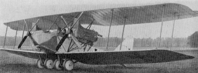
A.E.G. G I (K I)
First of the A.E.G. twin-engined bombers, which led eventually to the G IV, this aircraft had a crew of three, appeared early in 1915. Only a single machine was built. Engines, two 100 h.p. Mercedes D I. Span, 160 m. (52 ft. 6 in.). Length, 8.65 m. (28 ft. 4 1/2 in.). Weights: Empty, 1,160 kg. (2,552 lb.). Loaded, 1,954 kg. (3,199 lb.). Speed, 125 km.hr. (78.125 m.p.h.). Climb, 800 m. (2,624 ft.) in 10-12 min.
A.E.G. G II
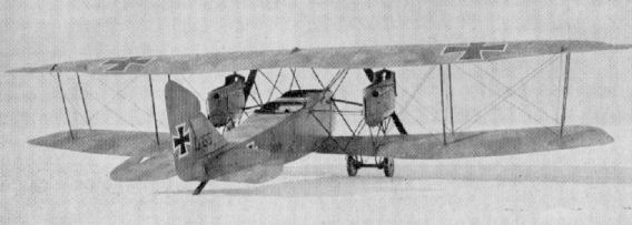
Appearing in July 1915, the G II was a slightly larger and more powerful version of the G I, and was seen with both triple and single tail. Armed with two to three machine-guns, it was used in small numbers by the Kampfgeschwadern. Some 15 to 20 aircraft were constructed. Engines, two 150 h.p. Benz Bz III. Span, 16.2 m. (53 ft. 1 7/8 in.). Length, 9.1 m. (29 ft. 10 3/8 in.). Weights: Empty, 1,450 kg. (3,190 lb.). Loaded, 2,470 kg. (5,434 lb.). Speed, 140 km.hr. (87.5 m.p.h.). Climb, 1,000 m. (3,280 ft.) in 11 min. With crew of three, 200 kg. of bombs could be carried externally.
A.E.G. G III
First of the A.E.G. twins to have balanced control surfaces, this series first appeared in December 1915. Limited numbers were produced. Kagohl I in Macedonia was equipped with this type in March 1916. Although similar to the subsequent G IV, the G III was distinguishable by the opposite hand of its airscrews, due to the gearing of the eight-cylinder 220 h.p. Mercedes D IV engines. Span, 18.44 m. (60 ft. 6 in.). Length, 9.2 m. (30 ft. 2 1/4 in.). Weights: Empty, 1,940 kg. (4,268 lb.). Loaded, 3,015 kg. (6,633 lb.). Speed, 158 km.hr. (98.75 m.p.h.). Climb, 1,000 m. (3,280 ft.) in 6 min. Range, 700 km. Crew, three. Armament, two manually operated machine-guns and 300 kg. bombs.
First of the A.E.G. twin-engined bombers, which led eventually to the G IV, this aircraft had a crew of three, appeared early in 1915. Only a single machine was built. Engines, two 100 h.p. Mercedes D I. Span, 160 m. (52 ft. 6 in.). Length, 8.65 m. (28 ft. 4 1/2 in.). Weights: Empty, 1,160 kg. (2,552 lb.). Loaded, 1,954 kg. (3,199 lb.). Speed, 125 km.hr. (78.125 m.p.h.). Climb, 800 m. (2,624 ft.) in 10-12 min.
A.E.G. G II
Appearing in July 1915, the G II was a slightly larger and more powerful version of the G I, and was seen with both triple and single tail. Armed with two to three machine-guns, it was used in small numbers by the Kampfgeschwadern. Some 15 to 20 aircraft were constructed. Engines, two 150 h.p. Benz Bz III. Span, 16.2 m. (53 ft. 1 7/8 in.). Length, 9.1 m. (29 ft. 10 3/8 in.). Weights: Empty, 1,450 kg. (3,190 lb.). Loaded, 2,470 kg. (5,434 lb.). Speed, 140 km.hr. (87.5 m.p.h.). Climb, 1,000 m. (3,280 ft.) in 11 min. With crew of three, 200 kg. of bombs could be carried externally.
A.E.G. G III
First of the A.E.G. twins to have balanced control surfaces, this series first appeared in December 1915. Limited numbers were produced. Kagohl I in Macedonia was equipped with this type in March 1916. Although similar to the subsequent G IV, the G III was distinguishable by the opposite hand of its airscrews, due to the gearing of the eight-cylinder 220 h.p. Mercedes D IV engines. Span, 18.44 m. (60 ft. 6 in.). Length, 9.2 m. (30 ft. 2 1/4 in.). Weights: Empty, 1,940 kg. (4,268 lb.). Loaded, 3,015 kg. (6,633 lb.). Speed, 158 km.hr. (98.75 m.p.h.). Climb, 1,000 m. (3,280 ft.) in 6 min. Range, 700 km. Crew, three. Armament, two manually operated machine-guns and 300 kg. bombs.
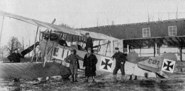
A.E.G. G III
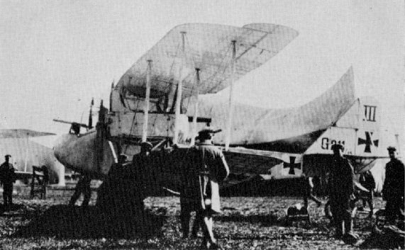
A scene at a German bomber base in 1916. A.E.G. G IIIs being prepared for a raid on Allied territory.
A.E.G. C IV
In 1916, with the realisation of the importance of aerial reconnaissance, the German Air Force decided to expand its II. Abt. and Fl. Abt. (A) Flights. Several factories undertook design and production of C type machines to enable newly created units to be raised to operational status with the minimum of delay.
The A.E.G. C IV was one of the types selected for production under this programme. Its short fuselage, combined with the considerable wingspan and the angularity of its tail surfaces, gave it a decidedly ungainly appearance and it was not an aircraft to delight the eye. Nevertheless, it performed very usefully with front-line units. The exact number built is not on record, but a total of 658 C type A.E.G.s was produced, and it is known that the C IV predominated.
With the exception of the wooden wing ribs, the A.E.G. C IV was built almost completely of steel tube of varying gauge and diameter. In this respect it differed widely from its Albatros, Aviatik and L.V.G. contemporaries. By virtue of its experience of welded construction, the Fokker factory at Schwerin was ordered to build the C IV under licence, a situation which the egotistical Anthony Fokker personally found extremely galling.
Power was provided by the 160 h.p. Mercedes D III motor, which, splendid engine though it was, was a far from adequate installation for an aircraft of this wingspan. The bulbous nose panelling surrounding it paid scant heed to the demands of streamlining, and a large rectangular Daimler Mercedes radiator encumbered the underside of the centre-section, being mounted directly under the main spar. A rhino-horn exhaust manifold of formidable proportions ejected vertically over the top wing. The fuselage basically a braced box-girder; longerons and transverse members were of 16 mm. diameter steel tube, except for the three rearmost stations, which were of 20 mm. tube, welded together with sheet steel lugs in the corners for the attachment of the bracing cables. A Ministry of Munitions report on a captured example stressed the quality of the welding. That considerable attention was paid to structural detail, if not to streamlining, is evidenced by the fact that at certain points in the fuselage where bracing wires lay in the same plane as cross members, such members were diagonally drilled and a small-diameter tube welded in place for the passage of the wire.
The wings were built on two steel tube spars some 40 mm. in diameter, the wooden ribs being interspaced with false ribs extending from the wooden, semicircular leading-edge member back to the front spar. The aileron wires ran through a steel tube in the lower wing mounted behind the front spar, which served as an additional structural member. The trailing edge was a simple wire member which imparted a slightly scalloped profile, characteristic of so many German aircraft. The ailerons themselves were also of steel tube frame, unbalanced, and those of the production aircraft had a distinctive "bite" out of the trailing edge unlike those of the prototype aircraft, which were parallel. With its shallow cut-out, the centre-section was supported on six steel struts in order to amply sustain the bulky radiator and gravity fuel tank which were fixed to it. The wings were rigged with a slight degree of sweep, not apparent from photographs, 1° 10' in the upper wing and 1° 5' in the lower. All struts were of streamlined steel tube and bracing was by stranded cable wires.
Again in all tail surfaces, steel tube was the constructional material; they were plain unbalanced surfaces of uniform "flat plate" section. A unique feature was the adjustable tail plane incidence. This could be pre-set to one of three different positions, according to the trim desired, and to permit this the tailplane bracing struts were ingeniously adjustable for length by virtue of a shackle end which screwed in, or out, of the top of the actual steel strut tube.
Streamlined steel tube (70 x 35 mm.) formed the vees of the undercarriage chassis, while the shock absorbers were of spiral steel springs. The tail skid was an extremely robust affair, welded from sheet steel, mounted on the base of the stern post, and internally sprung by four spiral springs in direct tension.
A total of 170 A.E.G. two-seaters were serving on all Fronts in June 1917, and 40 were still operational as late as August 1918.
TECHNICAL DATA
Description: Two-seat reconnaissance or artillery observation.
Manufacturers:
Allgemeine Elektrizitiits Gesellschaft (A.E.G.).
Fokker Flugzeugwerke G.m.b.H. Schwerin (Fok.).
Power Plant: 160 h.p. Mercedes D III 6 cylinder in-line water cooled.
Dimensions: Span, 13460 m. (44 ft. 2 in.). Length, 7150 m. (23 ft. 5 1/2 in.). Height, 3.350 m. (10 ft. 11 7/8 in.). Wing area, 39 sq.m. (421.2 sq.ft.).
Heights: Empty, 800 kg. (1,760 lb.). Loaded, 1,120 kg. (2,464 lb.).
Performance: Maximum speed, 158 km.hr. (98.75 m.p.h.). Initial climb, 1,000 m. (3,280 ft.) in 6 min. Ceiling, 5,000 m. (16,400 ft.). Duration, 4 hr.
Armament: Two machine-guns. One fixed Spandau for pilot and one free-firing Parabellum for observer.
A.E.G. C V
Designed to utilise the geared straight-eight-cylinder 220 h.p. Mercedes engine, the C V made its debut in February 1916. Only one machine was built, as the Albatros C V proved much superior. Engine, 220 h.p. Mercedes D IV. Span, 13.20 m. (43 ft. 3 3/4 in.). Length, 7.6 m. (24 ft. 11 1/4 in.). Area, 41.5 sq.m. (448 sq.ft.). Weights: Empty, 900 kg. (1,980 lb.). Loaded, 1,432 kg. (3,150 lb). Speed, 165 km.hr. (103.12 m.p.h.). Climb, 1,000 m. (3,280 ft.) in 5 min.
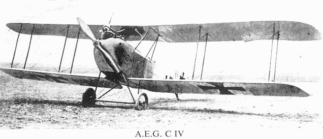
One of the Fokker-built A.E.G. C.IV two-seaters.
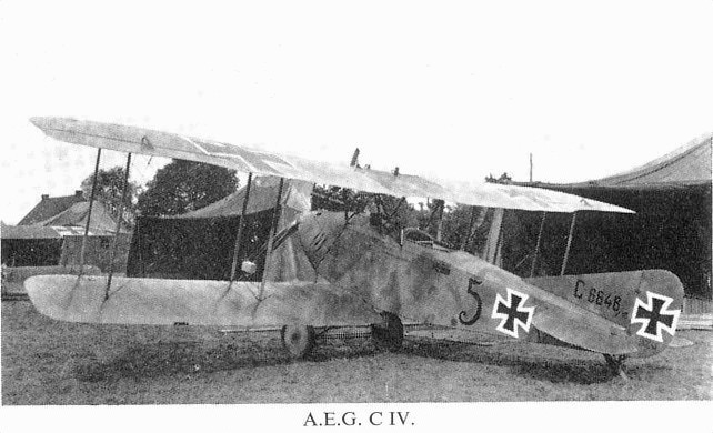
AEG C.IV 6648/16 of the second production batch with tactical number '5' served with Flieger Abteilung(A) 224, a Wurttemberg unit.
A.E.G. C VII
Two versions of the A.E.G. C VII appeared, in December 1916. Both were single-bay machines, with basically similar fuselage and tail, but one was built with straight wings and the other (illustrated below) with a heavily swept upper wing and a large spinner on the airscrew. Engine, 160 h.p. Mercedes D III. Span, 11.1 m. (36 ft. 5 1/8 in.). Length, 6.2 m. (20 ft. 4 1/8 in.). Weights: Empty, 758 kg. (1,668 lb.). Loaded, 1,118 kg. (2,462 lb.). Speed, 165 km.hr. (103.12 m.p.h.). Climb, 1,000 m. (3,280 ft.) in 4 min.
Two versions of the A.E.G. C VII appeared, in December 1916. Both were single-bay machines, with basically similar fuselage and tail, but one was built with straight wings and the other (illustrated below) with a heavily swept upper wing and a large spinner on the airscrew. Engine, 160 h.p. Mercedes D III. Span, 11.1 m. (36 ft. 5 1/8 in.). Length, 6.2 m. (20 ft. 4 1/8 in.). Weights: Empty, 758 kg. (1,668 lb.). Loaded, 1,118 kg. (2,462 lb.). Speed, 165 km.hr. (103.12 m.p.h.). Climb, 1,000 m. (3,280 ft.) in 4 min.
A.E.G. C VII
A.E.G. G IV
It is difficult to understand why the German High Command should have introduced the A.E.G. G IV operationally towards the end of 1916. It used the same two Mercedes D IVa power plants as its contemporary Friedrichshafen and Gotha bombers, but possessed neither their range nor lifting power. It was simply a slightly further refinement of the A.E.G. G I, G II and G III types which had preceded it in small numbers, and which had been used both as battle planes and bombers.
The wings consisted of a fixed centre-section with detachable swept-back outer panels. They were of composite construction and built on two 50 mm. diameter steel tube spars, spaced 3 ft. 8 1/2 in. apart. The wooden ribs were not of the usual plywood type but of solid wood (probably poplar) glued into grooved flanges. Lightening holes were cut in them and they were reinforced between with wooden uprights. The ribs were not directly fixed to the spars, but were loosely threaded on, held in place and correctly distanced by the wooden leading edge and wire trailing edge. False ribs were spaced between the main ribs. As in the A.E.G. C IV, two steel tubes (housing the aileron cables) ran through the lower wing panels, extending as far as the outer interplane struts, where the cables then ran up to the actuating crank of the large balanced ailerons on the upper wing. These were of steel tube framing and possessed the distinctive profile of the C IV ailerons. Steel tube compression members with cable bracing wires completed the internal structure of the wing panels.
The engines were mounted on a complicated system of steel struts attached directly to the lower wing spars and were additionally braced to the fuselage upper longerons and again to the lower wing spars immediately above the inboard undercarriage vee attachment points. A peculiarity of the engine mountings was the absence of any struts linking them to the top wing. A feature of all the A.E.G. twin-engined machines was the installation of the engines as tractor units when the majority of contemporary German twins seemed to favour a pusher arrangement. Car-type radiators were fitted immediately behind the propellers, and provision was made for the engine to be completely panelled in, although the top and often the side panels, were not used in practice.
As in the C IV and J types, welded steel tube was used for the construction of the fuselage and tail assembly. The fuselage was welded in one complete unit and not two or three sub-assemblies, as was sometimes the case with bigger aircraft. The nose section was covered with plywood, elsewhere fabric was used. The fixed fin surfaces of the tail were of a built-up highly cambered section, although the tall horn-balanced rudder and split elevators were still of approximate flat plate section. The loads imposed on the fin by the exceptionally tall rudder necessitated this being braced to the lop longerons with steel struts, a feature not always apparent from photographs. The tailplane was braced to the underside of the fuselage, again by steel struts but in more orthodox manner; it was adjustable to three different incidence settings.
Due to the combination of its comparatively high structural weight and relatively small size for a twin aircraft, the G IV could only carry a small load when fully fuelled, and for this reason it was mostly used for short-range tactical bombing behind the lines on the Western Front. On occasion it was used, without a bomb load, for long-distance reconnaissance and aerial photography.
On the port side of the rear cockpit were two racks for 25 lb. (10 kg.) bombs, and a third rack for the same size bombs under the floor between the main and rear cockpits. Provision was made to carry one 1 cwt. (50 kg.) bomb under each lower wing and a further two or three under the fuselage itself. All bombs were released by a control in the forward cockpit.
Although accommodation was sufficient for a crew of four, the normal complement was three. All these stations were interconnected and the crew could change position during flight as occasion demanded, but due to the extreme sensitivity of the longitudinal control the front cockpit usually remained occupied. The control column was headed with a wheel for aileron control. A steel tube could be fixed into the control column and a spare rudder-bar, linking with the pilots', let into the floor, thereby affording a measure of dual control in all but ailerons. The value of such a limited degree of control seems doubtful, but it probably enabled the copilot to make some sort of landing in an emergency.
The undercarriage was a twin-chassis affair of orthodox vee type construction and mounted directly under each power unit. Shock absorbers were of spiral steel springs, of which no less than 144 were used in the complete undercarriage. The tailskid was again a stout welded sheet steel component.
Although by no means a star performer, considerable numbers of G IVs were built and continued to operate up to the end of hostilities, some fifty still being in use in August 1918. The type was used for both day and night bombing raids over the Allied "back areas". Including the earlier G I, II and III machines, a total of 542 G types were manufactured by A.E.G.
An aircraft of increased span with three bay struts, and known as the G IVb, was built. Another experiment was the G IVk, with installation of the 2 cm. Becker cannon in the nose; several were built and assessed at the Front by the Schlastas.
TECHNICAL DATA
Purpose: Bombing and specialised reconnaissance.
Manufacturers: Allgemeine Elektrizitats Gesellschaft (A.E.G.).
Power Plant: Two 260 h.p. Mercedes D IVa 6 cylinder in-line water cooled.
Dimensions: Span, 18.40 m. (60 ft. 4 1/2 in.). Length, 9.70 m. (31 ft. 9 7/8 in.). Height, 3.90 m. (12 ft. 9 5/8 in.). Wing area, 67 sq.m. (675.36 sq.ft.).
Weights: Empty, 2,400 kg. (5,280 lb.). Loaded, 3,630 kg. (7,986 lb.).
Performance: Maximum speed, 165 km.hr. (103 m.p.h.). Initial climb, 1,000 m. (3,280 ft.) in 5 min. Ceiling, 4,500 m. (14,760 ft.). Duration, 3 1/4 hr. at full power. 4-5 hr. cruise.
Armament: Two Parabellum free-firing machine-guns. One on ring mounting in front cockpit; one on rail mounting traversing three sides of rectangular rear cockpit. Bomb-load: 880 lb.
A.E.G. G IVb
This aircraft was basically a standard G IV fitted with long-span wings. Engines, two 260 h.p. Mercedes D IVa. Span, 24.0 m. (78 ft. 9 in.). Length, 9.7 m. (31 ft. 9 7/8 in.). Weights: Empty, 2,453 kg. (5,397 lb.). Loaded, 3,700 kg. (8,140 lb.). Speed 160 km.hr. (100 m.p.h.). A second version (856/16) with biplane tail was also constructed.
A.E.G. G IV (serial G 155/16).
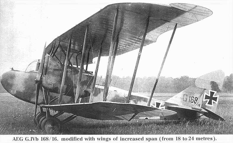
Three-bay AEG G.IVb G.168/16 was from the first G.IV production batch and was rebuilt as an extended-span G.IVb.
A.E.G. C VIII
An experimental single-bay two-seater of Oct. 1917. Multi-spar wings "ear"-type radiators and tail surfaces quite unlike previous A.E.G. designs. Engine, 160 h.p. Mercedes D III. Span, 9.5 m. (31 ft. 2 in.). Length, 6.9 m. (22 ft. 7 3/4 in.). Weights: Empty, 800 kg. (1,760 lb.). Loaded, 1,160 kg. (2,552 lb.). Speed, 170 km.hr. (106.25 m.p.h.). Climb, 1,000 m. (3,280 ft.) in 3.8 min.
A.E.G. C VIII Dr
This triplane version of the C VIII showed no improvement in climb, and speed was reduced to 165 km.hr. (103.12 m.p.h.). It appeared in December 1917 and did not develop beyond an experiment. Engine, 160 h.p. Mercedes D III. Span, Upper 11.2 m. (36 ft. 9 in.); Middle 10.8 m. (35 ft. 5 1/4 in.); Lower, 10.4 m. (35 ft. 1 1/4 in.). Otherwise as C VIII.
A.E.G. D I
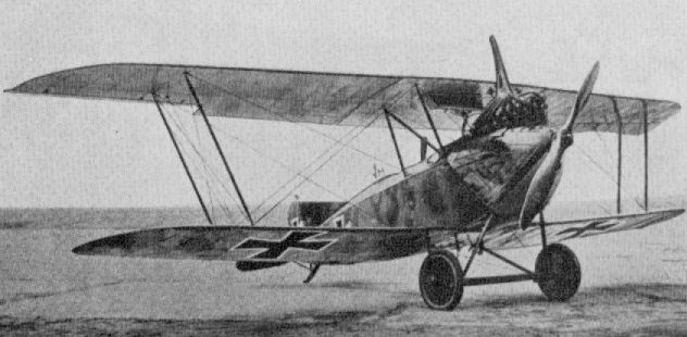
Entry of A.E.G. into the single-seat fighter field was marked in May 1917 by the appearance of the stocky D I. Two further prototypes, D 4401/17 and D 5002/17, were fitted with "ear"-type radiators and differed little except that D 5002/17 (below) had slightly longer radiator strips. Engine, 160 h.p. Mercedes D III. Span, 8.5 m. (27 ft. 10 3/4 in.). Length, 6-1 m. (20ft. 0 1/4 in.). Height, 2.65 m. (8 ft. 8 3/8 in.). Weights: Empty, 685 kg. (1,507 lb.). Loaded, 940 kg. (2,068 lb.). Speed, 220 km.hr. (137.5 m.p.h.). Climb, 1,000 m. (3,280 ft.) in 2.5 min., 5,000 m. (16,400 ft.) in 25 min.
A.E.G. Dr I
Introduced in October 1917, this triplane version of the D I offered no increase in climb performance, and the speed showed a reduction. It was developed no further. Engine, 160 h.p. Mercedes D III. Span, 9.4 m. (30 ft. 10 1/8 in.). Length, 61 m. (20 ft. 0 3/4 in.). Weights: Empty, 710 kg. (1,562 lb.). Loaded, 970 kg. (2,134 lb.). Speed, 170 km.hr. (106.25 m.p.h.).

The AEG D.I prototype, 4400/17, photographed at the Nieder-Neuendorf airfield in May 1917. Because the narrow airfoil section did not allow the installation of an airfoil radiator, a nose radiator was installed. The long exhaust stack reduced exhaust noise.
The AEG D.I owed nothing to the Nieuport and was a very fast, promising design. Powered by the same 160 hp Mercedes engine used in the Albatros fighters and mounting two machine guns, it climbed as well as the Albatros and reached 225 km/h (137 mph), making it the fastest fighter of its day. Three prototypes were built but after two unexplained fatal crashes, development was cancelled. Like all AEG designs its structure was welded steel tube.
The AEG D.I owed nothing to the Nieuport and was a very fast, promising design. Powered by the same 160 hp Mercedes engine used in the Albatros fighters and mounting two machine guns, it climbed as well as the Albatros and reached 225 km/h (137 mph), making it the fastest fighter of its day. Three prototypes were built but after two unexplained fatal crashes, development was cancelled. Like all AEG designs its structure was welded steel tube.

The A.E.G. D I. The photograph depicts the third prototype.
A.E.G. J I and J II
During 1917, formation and equipment of the Infanterie-Flieger units proceeded and, until specifically designed aircraft (e.g. Junkers J I, etc.) were available in sufficient quantity A.E.G. J Is and J IIs were allocated. Supply of these machines was a relatively simple matter, as the aircraft itself was virtually a C IV re-engined with a Benz and with a modified, armoured fuselage.
Powering the J I was the 200 h.p. Benz Bz IV, giving an increase of 40 h.p. over the Mercedes D III installed in the C IV. However, every ounce of this additional power was required to haul the extra 860 lb. of armour plate through the air. Armour plate extended from the nose to the aft extremity of the rear cockpit and was some 5.1 mm. thick. There were three panels either side of the fuselage, three underneath and a transverse bulkhead at the back of the rear cockpit to protect the observer from behind. The armour in no way formed part of the structure: it represented little more than sheets of steel fastened to the fuselage framework by set-screws entering clips clamped round structural members, with scant concession to shaping. In fact, the angular severity of the resultant nose contours was strongly reminiscent of a tank.
J Is were not fitted with any forward-firing armament, but two Spandau guns were bolted to tubular brackets on the rear cockpit floor. These fired forward and downwards at an angle of 45#' to facilitate Straffing of troops and harassing of ground targets, which were the prime duties of the A.E.G. J I. They were operated through Bowden wire controls from twin triggers mounted conveniently at the observer's right hand. Ammunition was belt-fed from a large supply drum mounted close to the guns. Rudimentary sighting was through a circular hole in the forward right-hand corner of the cockpit. For defensive purposes, the observer was equipped with the usual free-firing Parabellum gun on a ring mounting.
In the prototype machine the wing structure was identical with that of the C IV, but in operation, due to the added weight of the armour, the aeroplane was found to need a much greater degree of lateral control. To secure this without drastic revision of the flying surfaces, ailerons were added to the tips of the lower wings and simply connected to the upper ailerons with a rigid link strut, as the modus operandi was exactly the same as that of the earlier C type machine.
The remainder of the aircraft was almost pure C IV. Even the Daimler-Mercedes radiator was retained, though it now served a Benz engine. The number of spiral spring shock absorbers was reinforced to cater for the increased weight of the machine.
Later on, in 1918, a further development known as the J II was produced, but this differed little from the J I structurally. All control surfaces except for the lower ailerons, were now revised with large overhung horn balances which materially altered the appearance of the aircraft. To improve directional stability, the vertical fin was increased in area, raking up from the fuselage in a compound curve. The aileron link strut was located at the forward end of the operating crank instead of in the middle of the ailerons.
Altogether, according to the findings of the Inter Allied Commission immediately after the armistice, some 609 J type aircraft were produced by the A.E.G. concern.
TECHNICAL DATA
Purpose: Armoured Infantry Contact Patrol.
Manufacturers: Allgemeine Elektrizitiits Gesellschaft (A.E.G.).
Power Plant: 200 h.p. Benz Bz IV 6 cylinder in-line water cooled.
Dimensions: Span, 13.460 m. (44 ft. 2 in.). Length, 7.200 m. (7.900 m. J II) (23 ft. 7 1/2 in.) (25 ft. 11 in. J II). Height, 3.350 m. (10 ft. 11 7/8 in.). Wing area, 33.18 sq.m. (358.4 sq.ft.).
Weights: Empty, 1,455 kg. (1,480 kg. J II) (3,201 lb.) (3,256 lb. J II). Loaded, 1,740 kg. (1,765 kg. J II) (3,828 lb.) (3,883 lb. J II).
A.E.G. J.I
A.E.G. C IV N
The C IV N was produced as a night bomber in 1917. It was basically a C IV airframe with longer-span wings of three-bay format. Only one built. Engine, 150 h.p. Benz Bz III. Span, 15.3 m. (50 ft. 2 3/8 in.). Length, 7.3 m. (23 ft. 11 3/8 in.). Height, 3.3 m. (10 ft. 9 7/8 in.). Weights: Empty, 880 kg. (1,936 lb.). Loaded, 1,400 kg. (3,080 lb.). Speed, 143 km.hr. (89.4 m.p.h.). Climb, 3,000 m. (9.840 ft.) in 50 min. Duration, ca. 4 hours.
A.E.G. N I
This type was used as civil aircraft after the war, in which guise it is shown here. Engine, 150 h.p. Benz (200 h.p. Benz, civil). Span, 15.30 m. (50 ft. 2 1/2 ins.). Length, 7.30 m. (23 ft. 10 3/4 in.). Height, 3.30 m. (10 ft. 9 1/2 in.). Weights: Empty, 880 kg. (1,936 lb.). Loaded, 1,400kg. (3,050 lb.). Ceiling, 4,000 m. (13,120 ft.). Duration, 4 hr. Speed, 143 km.hr.
The AEG N.I was a long-span version of the AEG C.IV modified to carry more bombs, and this view clearly shows the key N.I recognition features. First, the N.I had a long wing with 3-bay bracing compared to the shorter, 2-bay wings of the C.IV. Next, the triangular bracing truss above the upper wing center section was required to strengthen the longer N.I wing against bending so it could pass the required load test. Unlike its daylight predecessor the AEG C.IV, the N.I did not have a fixed machine gun for the pilot; the observer's gun was thought sufficient for both strafing and defending the aircraft at night. The high exhaust stack directed the noise and flames away from the aircraft, which was important to maintain the pilot's night vision.Typical AEG sprayed camouflage on the upper surfaces is evident.
A.E.G. DJ I
This aircraft was designed as an armoured single-seat ground attack fighter, roughly equivalent to the British Sopwith Salamander. It first flew in September 1918, but the Armistice stopped further development. Braced with two bay I struts, it had no flying or landing cables. The fuselage was skinned with sheet aluminium. Engine, 195 h.p. Benz Bz IIIb vee eight, driving four-blade airscrew. Span, 10.0 m. (32 ft. 9 3/4 in.). Length, 6.69 m. (22 ft. 11 1/4 in.). Height, 3 0 m. (9 ft. 10 1/8 in.). Weights: Empty, 1,185 kg. (2,607 lb.). Loaded, 1,370 kg. (3,014 lb.). Speed, 180 km.hr. (112.5 m.p.h.). Climb, 1,000 m. (3,280 ft.) in 4 min.
This aircraft was designed as an armoured single-seat ground attack fighter, roughly equivalent to the British Sopwith Salamander. It first flew in September 1918, but the Armistice stopped further development. Braced with two bay I struts, it had no flying or landing cables. The fuselage was skinned with sheet aluminium. Engine, 195 h.p. Benz Bz IIIb vee eight, driving four-blade airscrew. Span, 10.0 m. (32 ft. 9 3/4 in.). Length, 6.69 m. (22 ft. 11 1/4 in.). Height, 3 0 m. (9 ft. 10 1/8 in.). Weights: Empty, 1,185 kg. (2,607 lb.). Loaded, 1,370 kg. (3,014 lb.). Speed, 180 km.hr. (112.5 m.p.h.). Climb, 1,000 m. (3,280 ft.) in 4 min.
A.E.G. G IVk
Yet another variant of the G IV. Fitted with 2 cm. Becker Cannon in an armoured nose panel, and intended for use with the Schlachtgeschwadern in 1918, it is not thought to have been used operationally. A biplane tail unit was fitted and armour plate panels also enclosed the 260 h.p. Mercedes D IVa engines. Standard G IV wing cellule of 18.4 m. (60 ft. 44 in.) was fitted. A second version with G V wing cellule (G IVk 503/18) also existed.
Yet another variant of the G IV. Fitted with 2 cm. Becker Cannon in an armoured nose panel, and intended for use with the Schlachtgeschwadern in 1918, it is not thought to have been used operationally. A biplane tail unit was fitted and armour plate panels also enclosed the 260 h.p. Mercedes D IVa engines. Standard G IV wing cellule of 18.4 m. (60 ft. 44 in.) was fitted. A second version with G V wing cellule (G IVk 503/18) also existed.
A.E.G. G V
Produced for longer-range work than the G IV, the prototype G V appeared in May 1918. None were completed in time for operational service. In 1919 some of these aircraft were used on the first German air line Deutsche Luftreederei, one machine flying from Berlin to Eskjo in Sweden in 4 hr. 7 min. Engines, two 260 h.p. Mercedes D IVa. Span, 27.24 m. (89 ft. 4 1/2 in.). Length, 10.8 m. (35 ft. 9 1/2 in.). Height, 4.5 m. (14 ft. 9 1/8 in.). Weights: Empty, 2,700 kg. (5,940 lb.). Loaded, 4,600 kg. (10,120 lb.). Speed, 145 km.hr. (90.625 m.p.h.). Climb, 1,000 m. (3,280 ft.) in 6 min. Duration, 5-6 hr. Armament, 2/3 manually operated machine-guns. 600 kg. (1,320 lb.) bombs.
Produced for longer-range work than the G IV, the prototype G V appeared in May 1918. None were completed in time for operational service. In 1919 some of these aircraft were used on the first German air line Deutsche Luftreederei, one machine flying from Berlin to Eskjo in Sweden in 4 hr. 7 min. Engines, two 260 h.p. Mercedes D IVa. Span, 27.24 m. (89 ft. 4 1/2 in.). Length, 10.8 m. (35 ft. 9 1/2 in.). Height, 4.5 m. (14 ft. 9 1/8 in.). Weights: Empty, 2,700 kg. (5,940 lb.). Loaded, 4,600 kg. (10,120 lb.). Speed, 145 km.hr. (90.625 m.p.h.). Climb, 1,000 m. (3,280 ft.) in 6 min. Duration, 5-6 hr. Armament, 2/3 manually operated machine-guns. 600 kg. (1,320 lb.) bombs.
A.E.G. P.E.
This experimental single-seat triplane appeared early in 1918. It featured dural tubular wing spars and the aluminium-sheel-covered fuselage was also armoured. It was from this aircraft the later DJ I stemmed. It is certain a vee-eight-type motor was fitted, probably the 195 h.p. Benz Bz IIIb as in the DJ I. Span, 11.2 m. (36 ft. 9 in.). Length, 6.6 m. (21 ft. 7 7/8 in.). Weights: Empty, 1,182kg.(2,600 lb.). Loaded, 1,412kg.(3,106 lb.). Speed, 166 km.hr. (103.75 m.p.h.). Climb, 1,000 m. (3,280 ft.) in 5.8 min. Armament, two Spandau machine-guns firing forward and four small bombs.
This experimental single-seat triplane appeared early in 1918. It featured dural tubular wing spars and the aluminium-sheel-covered fuselage was also armoured. It was from this aircraft the later DJ I stemmed. It is certain a vee-eight-type motor was fitted, probably the 195 h.p. Benz Bz IIIb as in the DJ I. Span, 11.2 m. (36 ft. 9 in.). Length, 6.6 m. (21 ft. 7 7/8 in.). Weights: Empty, 1,182kg.(2,600 lb.). Loaded, 1,412kg.(3,106 lb.). Speed, 166 km.hr. (103.75 m.p.h.). Climb, 1,000 m. (3,280 ft.) in 5.8 min. Armament, two Spandau machine-guns firing forward and four small bombs.
A.E.G. R.I
Two "Giant" machines were ordered from A.E.G. during 1916, R I 21/16 and R. I 22/16. The four engines were placed together inside the fuselage, the airscrews being driven through gear boxes and transmission shafts. Initially, four-bladed airscrews were fitted, but later a two-blade type was substituted. First flights of the R I 21/16 took place during 1916 and were considered to be satisfactory. Later, during flight trials on 3rd September, a propeller disintegrated due to the laminating glue not having been allowed sufficient time to harden thoroughly. As a consequence the transmission shaft tore loose and smashed a centre-section strut, which caused the machine to crash with a loss of seven lives. R I 22/16 was still incomplete at the end of the war and was eventually scrapped. Engines, four 260 h.p. Mercedes D IVa driving two airscrews through transmission geared down to 750 r.p.m. Span, 36.0 m. (118 ft. 1 1/2 in.). Length, 19.5 m. (63 ft. 11 1/2 in.). Weights: Empty, 9,000 kg. (19,845 lb.). Loaded, 12,500 kg. (28,003 lb.).
Two "Giant" machines were ordered from A.E.G. during 1916, R I 21/16 and R. I 22/16. The four engines were placed together inside the fuselage, the airscrews being driven through gear boxes and transmission shafts. Initially, four-bladed airscrews were fitted, but later a two-blade type was substituted. First flights of the R I 21/16 took place during 1916 and were considered to be satisfactory. Later, during flight trials on 3rd September, a propeller disintegrated due to the laminating glue not having been allowed sufficient time to harden thoroughly. As a consequence the transmission shaft tore loose and smashed a centre-section strut, which caused the machine to crash with a loss of seven lives. R I 22/16 was still incomplete at the end of the war and was eventually scrapped. Engines, four 260 h.p. Mercedes D IVa driving two airscrews through transmission geared down to 750 r.p.m. Span, 36.0 m. (118 ft. 1 1/2 in.). Length, 19.5 m. (63 ft. 11 1/2 in.). Weights: Empty, 9,000 kg. (19,845 lb.). Loaded, 12,500 kg. (28,003 lb.).
Ago C I
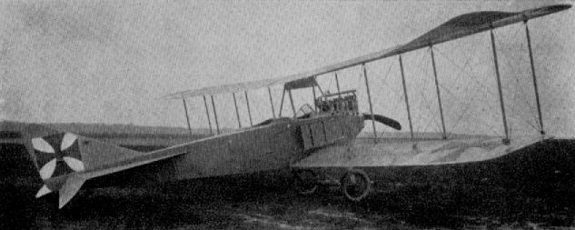
Of twin-boom pusher layout, this two-seater was used from the summer of 1915 on reconnaissance duties. Although only produced in limited quantities, the type was often seen on the Western Front, its unusual configuration making it readily recognisable. Engine, 150 h.p. Benz III or 160 h.p. Mercedes D III. Span, 14.5 m. (47 ft. 7 in.). Length, 9.84 m. (32 ft. 3 3/8 in.). Weights: Empty, 800 kg. (1,760 lb.). Loaded, 1,320 kg. (2,904 lb.). Speed, 145 km.hr. (90.625 m.p.h.). Climb, 1,000 m. (3,280 ft.) in 7-10 min. Duration, ca. 4 hr. Armament, one manually operated machine-gun in nose.
Ago C II
Appearing later in 1915, the C II was a somewhat cleaner version of the C I with revised triangular tail surfaces and the more powerful 220 h.p. Benz IV engine. Span, 14.5 m. (47 ft. 7 in.). Length, 9.84 m. (32 ft. 3 3/8 in.). Weights: Empty, 1,360 kg. (2,992 lb.). Loaded, 1,946 kg. (4,281 lb.). Speed, 137 km.hr. (85.625 m.p.h.). Armament, one manually operated machine-gun in nose. A variant with extended three-bay wings which spanned 18.3 m. (60 ft. 0 1/2 in.).

Ago C II (three-bay)
Ago C I W
Virtually a C I mounted on a float chassis, only one machine was handed over to the Navy for assessment. It bore the Naval serial 115. Engine, 150 h.p. Benz Bz III. Span, 14.5 m. (47 ft. 7 in.). Length, 10.4 m. (34 ft. 1 1/2 in.). No other data available.
Ago C II W
Two examples of the three-bay C II mounted on floats were supplied to the Navy in 1915. Serials 539 (illustrated) and 586. The 220 h.p. Benz IV engine was installed as in the land-plane, although that in 586 was fitted with a four-blade propeller. Span, 18.3 m. (60 ft. 0 5/8 in.). Length, 11.24 m. (36 ft. 10 5/8 in.).
Ago DV 3
This neat little single-seat unarmed biplane appeared early in 1915, and it is believed that only one was built. Power unit was the 100 h.p. Oberursel U I rotary, which gave a speed of approximately 150 km.hr. (93.75 m.p.h.) and a climb to 1,000 m. (3,280 ft.) in 8 min.
This neat little single-seat unarmed biplane appeared early in 1915, and it is believed that only one was built. Power unit was the 100 h.p. Oberursel U I rotary, which gave a speed of approximately 150 km.hr. (93.75 m.p.h.) and a climb to 1,000 m. (3,280 ft.) in 8 min.
Ago C III
Still retaining the twin-boom layout, the C III was a smaller single-bay machine powered with the 160 h.p. Mercedes D III engine. Span, 11.0 m. (36 ft. 1 1/8 in.). Length, 7.0 m. (22 ft. 1 5/8 in.). Only one built. No other data available.
Still retaining the twin-boom layout, the C III was a smaller single-bay machine powered with the 160 h.p. Mercedes D III engine. Span, 11.0 m. (36 ft. 1 1/8 in.). Length, 7.0 m. (22 ft. 1 5/8 in.). Only one built. No other data available.
Ago C IV
The name Ago was first borne in 1911 by the products of Aeroplanbau G. Otto und Alberti. In 1912 Ago Flugzeugwerke G.m.b.H. was founded as a branch of the Otto Company in Munich (the name Ago being derived from the initials of Aerowerke Gustav Otto), and early in the First World War produced the twin-boom C I and C II types in small numbers. These were designed by the Swiss engineer A. Haefeli, who was earlier with the Farman concern and later returned to Switzerland.
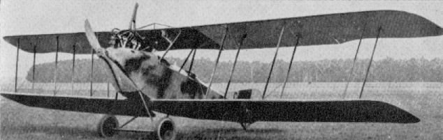
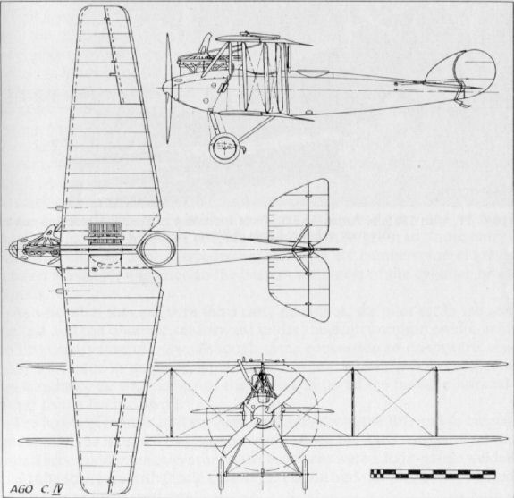
During 1916 Ago made an attempt to produce a high-performance two-seater, mainly for reconnaissance duties, with a good field of defensive fire. This eventually emerged in the shape of the C IV. Initially this machine appeared without a fixed vertical fin and with normal incidence bracing wires between the closely spaced outer interplane struts. In the production version a vertical fin was added to improve directional stability: it also eased the strain of piloting over long distances. At a later date the cable incidence bracing of the interplane struts was replaced by a rigid diagonal strut, resulting in an elongated "N" configuration of streamlined steel tube.
The most unusual feature of the Ago C IV was the tapering of the fabric covered wings which, as will be seen from the G.A. drawing, tapered quite sharply and uniformly from the maximum chord at the centre-section to the minimum chord at the square cut tip. Not only were the wings tapered but the two fabric-bound, main box-spars of Danzig pine also converged from root to tip. The ribs were of I-section, formed by a poplar web (fretted with the usual lightening holes) with ash capping strips, and not only was every rib in each panel a different size, but the distances on each rib where the spars intersected were different. As the wings also tapered in thickness from root to tip, further manufacturing complications were added, and it was undoubtedly this factor that precluded greater numbers of the aircraft being built. Although efficient, the Ago C IV took far too long to construct.
Other unique features of the wing structure were the closely spaced outer struts and the omission of the inner front interplane strut. This gave the observer an additional, limited, forward field of fire through the wings. It is of interest to note that on an Ago C IV captured by the Allies, a wire was fitted where this strut would normally have been and in the ensuing report in contemporary journals this can be mis-interpreted as a standard fitting. Flying and landing wires were also dispensed with at the forward spar locations. At the rear spar stations both sets of cables appeared in the outer bay: the inner bay was braced only by duplicated flying wires. This undoubtedly helped to minimise drag and consequently to improve performance. All four ailerons had a marked degree of washout and were linked with a streamlined steel strut. They were hinged to a false spar and actuated by a crank fixed to the upper ailerons which was operated by cables running through the lower wing, then over a pulley and up to the crank, adjacent to the interplane struts. On the earlier production machines ailerons were attached to the top wing only.
The radiator and gravity fuel tank were housed respectively in the root section of the starboard and port centre-sections and the piping ran through the centre-section struts, for added cleanliness of design. The main fuel tank was underneath the pilot's seat.
The fuselage structure was orthodox in design, but of unusual composite construction, with four wooden longerons (spruce aft of the rear cockpit and ash forward) and horizontal and vertical spacers of steel tube. With internal wire bracing aft of the cockpit section, and diagonal steel tube forward, a strong braced box-girder structure was formed. The curved top decking to the rear of the cockpits was a completely detachable, light framework which greatly facilitated access for servicing. A clean nose entry was achieved by the use of a spinner on the airscrew and the complimentary shaping of the metal panels around the nose and cylinder block of the 220 h.p. Benz engine. Also worthy of note was the complete enclosing of the forward-firing fixed Spandau gun. The remainder of the fuselage, which tapered to a vertical knife-edge, was ply-covered from the front undercarriage strut to the rear cockpit, aft of which it was fabric covered, except underneath, where it was ply-covered aft of the rear cockpit and aluminium covered forward of that point.
The tailplane had two box-spars, wooden ribs and split, unbalanced elevators, all of which were fabric covered. The balanced, comma-shaped rudder and fin were of light-gauge steel tubes and also fabric covered. Light steel struts braced the fin to the tailplane and the tailplane to the fuselage.
Streamlined steel tube vees formed the basis of the undercarriage chassis, with diagonal bracing between the front struts. The axle and spreader-bars were enclosed by a streamlined fairing, and a "claw" type brake was fixed to the middle of the axle.
The Ago C IV was active in small numbers during 1917. In February, Hans Schroder of Fl. Abt. 284A recorded that: "At last the new machines arrived. They were not Rumplers but Agos, with very pointed wings, and our first flights showed them to be most unstable in the air. Their climbing capacity was not very great and we were very disappointed with them."
Lt. Vater (an observer with Schroder's unit) had a remarkable escape during a photo reconnaissance on 18th February 1917 when his Ago was hit by A.A. fire at 3,000 m. over Thann (Vosges) and his pilot Sgt. Lulsdorf was killed. The machine fell in a series of wild inverted dives with Vater clinging upside down in the rear cockpit. The Ago eventually hit the ground inverted. Vater was dazed but heard infantrymen call to him and then assist him into a trench as the French began to shell the aircraft. Besides cuts and bruises he sustained a broken jaw, but was able to return to his Section within ten days.
About 70 Ago C IVs were in service in 1917-18 and not all the 260 aircraft ordered from sub-contractors were delivered.
TECHNICAL DATA
Purpose: Two-seat reconnaissance.
Manufacturers:
Ago Flugzeugwerke (Ago).
Flugzeugbau Schutte Lanz (250 aircraft) (Schul).
Waggonfabrik Joseph Rathgeber (10 aircraft) (Rat).
Power Plant: 220 h.p. Benz Bz IV 6 cylinder in-line water cooled.
Dimensions: Span, 11.90 m. (39 ft. 0 1/2 in.). Length, 8.25 m. (26 ft. 4 3/4 in.). Height, 3.50 m. (11 ft. 5 3/4 in.). Wing area, 37.5 sq.m. (405 sq.ft.).
Weights: Empty, 900 kg. (1,980 lb.). Loaded, 1,350 kg. (2,970 lb.).
Performance: Maximum speed, 190 km.hr. (118.75 m.p.h.). Initial climb, 3,000 m. (9,840 ft.) in 22 min. Ceiling, 5,500 m. (18,040 ft.). Duration, 4 hr. (750 km. range).
Armament: One fixed Spandau machine-gun for pilot. One free-firing Parabellum machine-gun for observer.
The name Ago was first borne in 1911 by the products of Aeroplanbau G. Otto und Alberti. In 1912 Ago Flugzeugwerke G.m.b.H. was founded as a branch of the Otto Company in Munich (the name Ago being derived from the initials of Aerowerke Gustav Otto), and early in the First World War produced the twin-boom C I and C II types in small numbers. These were designed by the Swiss engineer A. Haefeli, who was earlier with the Farman concern and later returned to Switzerland.
During 1916 Ago made an attempt to produce a high-performance two-seater, mainly for reconnaissance duties, with a good field of defensive fire. This eventually emerged in the shape of the C IV. Initially this machine appeared without a fixed vertical fin and with normal incidence bracing wires between the closely spaced outer interplane struts. In the production version a vertical fin was added to improve directional stability: it also eased the strain of piloting over long distances. At a later date the cable incidence bracing of the interplane struts was replaced by a rigid diagonal strut, resulting in an elongated "N" configuration of streamlined steel tube.
The most unusual feature of the Ago C IV was the tapering of the fabric covered wings which, as will be seen from the G.A. drawing, tapered quite sharply and uniformly from the maximum chord at the centre-section to the minimum chord at the square cut tip. Not only were the wings tapered but the two fabric-bound, main box-spars of Danzig pine also converged from root to tip. The ribs were of I-section, formed by a poplar web (fretted with the usual lightening holes) with ash capping strips, and not only was every rib in each panel a different size, but the distances on each rib where the spars intersected were different. As the wings also tapered in thickness from root to tip, further manufacturing complications were added, and it was undoubtedly this factor that precluded greater numbers of the aircraft being built. Although efficient, the Ago C IV took far too long to construct.
Other unique features of the wing structure were the closely spaced outer struts and the omission of the inner front interplane strut. This gave the observer an additional, limited, forward field of fire through the wings. It is of interest to note that on an Ago C IV captured by the Allies, a wire was fitted where this strut would normally have been and in the ensuing report in contemporary journals this can be mis-interpreted as a standard fitting. Flying and landing wires were also dispensed with at the forward spar locations. At the rear spar stations both sets of cables appeared in the outer bay: the inner bay was braced only by duplicated flying wires. This undoubtedly helped to minimise drag and consequently to improve performance. All four ailerons had a marked degree of washout and were linked with a streamlined steel strut. They were hinged to a false spar and actuated by a crank fixed to the upper ailerons which was operated by cables running through the lower wing, then over a pulley and up to the crank, adjacent to the interplane struts. On the earlier production machines ailerons were attached to the top wing only.
The radiator and gravity fuel tank were housed respectively in the root section of the starboard and port centre-sections and the piping ran through the centre-section struts, for added cleanliness of design. The main fuel tank was underneath the pilot's seat.
The fuselage structure was orthodox in design, but of unusual composite construction, with four wooden longerons (spruce aft of the rear cockpit and ash forward) and horizontal and vertical spacers of steel tube. With internal wire bracing aft of the cockpit section, and diagonal steel tube forward, a strong braced box-girder structure was formed. The curved top decking to the rear of the cockpits was a completely detachable, light framework which greatly facilitated access for servicing. A clean nose entry was achieved by the use of a spinner on the airscrew and the complimentary shaping of the metal panels around the nose and cylinder block of the 220 h.p. Benz engine. Also worthy of note was the complete enclosing of the forward-firing fixed Spandau gun. The remainder of the fuselage, which tapered to a vertical knife-edge, was ply-covered from the front undercarriage strut to the rear cockpit, aft of which it was fabric covered, except underneath, where it was ply-covered aft of the rear cockpit and aluminium covered forward of that point.
The tailplane had two box-spars, wooden ribs and split, unbalanced elevators, all of which were fabric covered. The balanced, comma-shaped rudder and fin were of light-gauge steel tubes and also fabric covered. Light steel struts braced the fin to the tailplane and the tailplane to the fuselage.
Streamlined steel tube vees formed the basis of the undercarriage chassis, with diagonal bracing between the front struts. The axle and spreader-bars were enclosed by a streamlined fairing, and a "claw" type brake was fixed to the middle of the axle.
The Ago C IV was active in small numbers during 1917. In February, Hans Schroder of Fl. Abt. 284A recorded that: "At last the new machines arrived. They were not Rumplers but Agos, with very pointed wings, and our first flights showed them to be most unstable in the air. Their climbing capacity was not very great and we were very disappointed with them."
Lt. Vater (an observer with Schroder's unit) had a remarkable escape during a photo reconnaissance on 18th February 1917 when his Ago was hit by A.A. fire at 3,000 m. over Thann (Vosges) and his pilot Sgt. Lulsdorf was killed. The machine fell in a series of wild inverted dives with Vater clinging upside down in the rear cockpit. The Ago eventually hit the ground inverted. Vater was dazed but heard infantrymen call to him and then assist him into a trench as the French began to shell the aircraft. Besides cuts and bruises he sustained a broken jaw, but was able to return to his Section within ten days.
About 70 Ago C IVs were in service in 1917-18 and not all the 260 aircraft ordered from sub-contractors were delivered.
TECHNICAL DATA
Purpose: Two-seat reconnaissance.
Manufacturers:
Ago Flugzeugwerke (Ago).
Flugzeugbau Schutte Lanz (250 aircraft) (Schul).
Waggonfabrik Joseph Rathgeber (10 aircraft) (Rat).
Power Plant: 220 h.p. Benz Bz IV 6 cylinder in-line water cooled.
Dimensions: Span, 11.90 m. (39 ft. 0 1/2 in.). Length, 8.25 m. (26 ft. 4 3/4 in.). Height, 3.50 m. (11 ft. 5 3/4 in.). Wing area, 37.5 sq.m. (405 sq.ft.).
Weights: Empty, 900 kg. (1,980 lb.). Loaded, 1,350 kg. (2,970 lb.).
Performance: Maximum speed, 190 km.hr. (118.75 m.p.h.). Initial climb, 3,000 m. (9,840 ft.) in 22 min. Ceiling, 5,500 m. (18,040 ft.). Duration, 4 hr. (750 km. range).
Armament: One fixed Spandau machine-gun for pilot. One free-firing Parabellum machine-gun for observer.
Ago C VII
Prototype only constructed. Engine 220 h.p. Benz Bz IV. No data available. The machine appears to utilise standard C IV fuselage and tail, with steel strip bracing in place of the usual cables.
Ago C VIII
This aircraft was virtually a re-engined C VII with a 260 h.p. Mercedes D IVa; there was also some revision of the tail surfaces. No other data available.
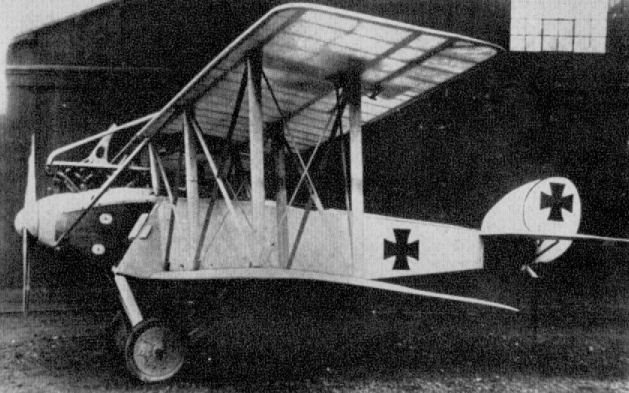
The Ago C.VII in its initial configuration was built in 1916. (Peter M. Grosz Collection/STDB)
Ago S I
Two of these single-seat aircraft were built, but were not completed before the war ended. They were designed for low-level attack, and probably had some degree of protective armour. Armament was given as two Spandau machine-guns and one 2 cm. cannon, although how the cannon was installed is not known. The photograph is the only one known to exist and, although poor, it does show well the split undercarriage chassis, which was considerably ahead of its time. Engine: 260 h.p. Basse und Selve BuS III.
Two of these single-seat aircraft were built, but were not completed before the war ended. They were designed for low-level attack, and probably had some degree of protective armour. Armament was given as two Spandau machine-guns and one 2 cm. cannon, although how the cannon was installed is not known. The photograph is the only one known to exist and, although poor, it does show well the split undercarriage chassis, which was considerably ahead of its time. Engine: 260 h.p. Basse und Selve BuS III.
Albatros B I
Designed and built before the war, small numbers of the B I were impressed for reconnaissance and school duties in August 1914. As was usually the case with these early machines, the pilot sat in the rear cockpit. One-bay and two-bay variants also existed. Engine, 100 h.p. or 110 h.p. Mercedes D I or D II. Span, 14.48 m. (47 ft. 6 1/8 in.). Length, 8.57 m. (28 ft. 1 1/2 in.). Height, 3.15 m. (10 ft. 4 in.). Weights: Empty, 747 kg. (1,643.4 lb.). Loaded, 1,080 kg. (2,376 lb.). Speed, ca. 105 km.hr. (65.625 m.p.h.). Climb, 800 m. (2,624 ft.) in 10 min. Duration, ca. 4 hr.
Designed and built before the war, small numbers of the B I were impressed for reconnaissance and school duties in August 1914. As was usually the case with these early machines, the pilot sat in the rear cockpit. One-bay and two-bay variants also existed. Engine, 100 h.p. or 110 h.p. Mercedes D I or D II. Span, 14.48 m. (47 ft. 6 1/8 in.). Length, 8.57 m. (28 ft. 1 1/2 in.). Height, 3.15 m. (10 ft. 4 in.). Weights: Empty, 747 kg. (1,643.4 lb.). Loaded, 1,080 kg. (2,376 lb.). Speed, ca. 105 km.hr. (65.625 m.p.h.). Climb, 800 m. (2,624 ft.) in 10 min. Duration, ca. 4 hr.
Albatros B I
Albatros W 1
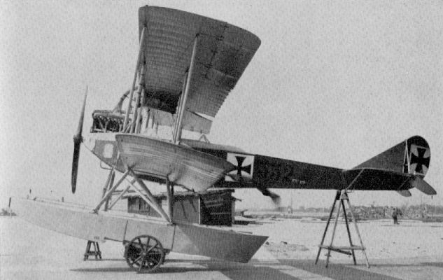
Powered with 150 h.p. Benz III, the W I was basically an unarmed reconnaissance seaplane version of the three-bay Albatros B II land machine.
Powered with 150 h.p. Benz III, the W I was basically an unarmed reconnaissance seaplane version of the three-bay Albatros B II land machine.
Albatros W 1
Albatros B II
Before the introduction of the C class machine with an engine of upwards of 150 h.p., all unarmed two-seater biplanes in the German air force came into the B category irrespective of power. They were used initially as reconnaissance machines and subsequently for primary training duties.
One such machine within this category to see long and widespread usage was the Albatros B II. It was a development of the pre-war three-bay Albatros B I machine, and was itself also of pre-war origin. The immensely strong plywood covered, slab-sided fuselage (first designed and used by Dipl. Ing. Grohmann in some ten aircraft before the B I), and which was to become the hallmark of so many Albatros two-seaters, was continued. It was based on four main longerons which were of ash forward of the cockpits and spruce aft of this point, and tapered to a vertical knife-edge at the rear. A rounded metal panel at the extreme nose end provided evidence that some, albeit very little, consideration had been given to "nose entry" otherwise the 100 h.p. Mercedes engine, with its cumbersome chimney exhaust manifold, was fitted to the bearers with most of the cylinder block exposed.
As was often the case with these early machines, the pilot sat in the rear cockpit and the observer sat forward under the centre-section trestle, with no little restriction of view, although some concession to downward visibility was made in the large, square cut-outs in the lower wing roots. The usual radiator accoutrements of the period cluttered the fuselage sides adjacent to the front cockpit.
The large, triangular, tail surfaces stemming from the B I, and to be perpetuated in the later C I, were to be seen. Both the fixed surfaces and the unbalanced rudder and elevator control surfaces were a light-gauge welded steel tube structure with fabric covering. The fin and tail-plane were braced with a streamlined steel strut.
In the wing structure there was little departure from previous practice except to standardise on a two-bay cellule, with the top wing of slightly greater span than the bottom. By being built up on two box-spars, with the rearmost spar at approximately mid-chord and with wooden ribs of thin aerofoil section, an extremely flexible trailing edge resulted, which obtained a considerable degree of inherent stability. This asset was considered a prerequisite in these early aeroplanes and characterised many subsequent Albatros two-seaters. The ailerons were of the same structural medium as the tail surfaces and had a slight inverse taper with considerable wash-out. The operating cables were rather untidily run externally along the surfaces of the lower wing and led up to the actuating crank over pulleys near the lower extremity of the rear, outer, interplane struts.
A quite orthodox vee-type undercarriage chassis, of streamline section steel tube, was fitted, and a claw-type brake was mounted on the centre of the axle. The ash tailskid was mounted externally on an inverted pylon structure and sprung with elastic shock chord.
The Albatros B II operated on reconnaissance duties from the beginning of the War until well into 1915, when the hostile activities of the Allied scouts hastened the withdrawal of the B type machines and their replacement with the armed, and more powerful, C type two-seaters. However, the docility of the Albatros B II's flying characteristics, combined with the economy of its low horse-power motor, admirably suited it for training duties, and in such manner it continued to serve the German flying services.
At a later date the airframe was strengthened, especially the tail section, and the radiators were removed from the fuselage sides to a neater installation in front of the centre-section leading-edge; additionally 100 h.p. Mercedes D I, 120 h.p. Mercedes D II or 120 h.p. Argus As II engines were installed. In this version the machine was known as the B IIa, otherwise it differed little from the B II. Dual control was fitted and the machine was used almost exclusively for ab initio pilot training until the end of the War.
TECHNICAL DATA
Description: Two-seat reconnaissance and training duties.
Manufacturers: Albatros Werke G.m.b.H. (Alb.).
Sub-contractors: Ostdeutsche Albatros Werke (OAW), Bayerische Flugzeug-Werke A.G. (Bay), Luftfahrzeug Gesellschaft (Rol), Linke und Hofmann Werke (IIa only) (Li), Mercur Flugzeugbau (Mer), Kondor Flugzeug-Werke G.m.b.H. (Kon) (IIa only), Refla Militar-Werksliitlcn. Warschau(II only).
Power Plant: One 100 h.p. Mercedes 6 cylinder in-line water-cooled engine (B II and IIa). Alternatively: 110 h.p. Bz II (B II), 120 h.p. Mercedes D II (B II and IIa), 120 h.p. Argus As II (B IIa).
Dimensions: Span, 1280 m. (42 ft. 0 in.) B II; 12.960 m. (42 ft. 6 1/4 in.) B IIa. Length, 7.63 m. (25 ft. 0 3/8 in.). Height, 315 m. (10 ft. 4 in.). Wing area, 40.12 sq.m. (433 sq.ft.) B II; 40.64 sq.m. (439 sq.ft.) B IIa.
Weights: Empty, 723 kg. (1,591 lb.) B II; 698 kg. (1,536 lb.) B IIa. Loaded, 1,071 kg. (2,356 lb.) B II; 1,078 kg. (2,372 lb.) B IIa.
Performance: Maximum speed, 105 km.hr. (66 m.p.h.) B II; 120 km.hr. (75 m.p.h.). B IIa. Initial climb, 800 m. (2,624 ft.) in 10 min. B II: (2,624 ft.) in 8.2 min. B IIa. Ceiling, 3,000 m. (9,840 ft.). Duration, 4 hr.
Armament: Nil.
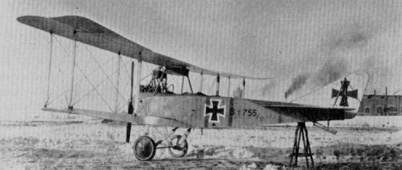
Albatros B II (100 h.p. Mercedes D I) .
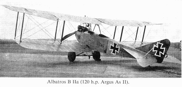
Albatros B IIa (120 h.p. Argus As II) .
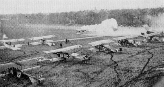
A varied collection of two-seaters at a German airfield in 1915. The aircraft are Albatros B IIs , Aviatik B Is and B IIs.
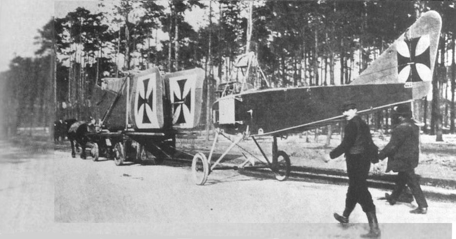
Albatros B.II reconnaissance biplane of 1915, as arranged for road transport.
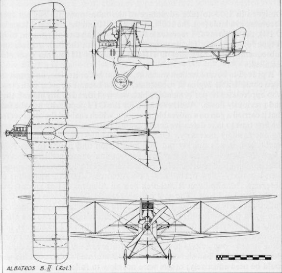
Albatros L 3
An unarmed single-seat scout type. Probably late 1914 or early 1915. Powered with 100 h.p. Gnome. According to records six machines of the type were constructed.
Albatros L 9
This little single-seat unarmed machine, designed by Dorner, was truly the precursor of the later famous D series. The thick, high-lift wings, later seen in the C IV, G II and G III types, may be observed. The fragility of the single interplane struts and absence of bracing cables would appear to indicate that the wing panels were a near cantilever structure. Power unit was the 100 h.p. Mercedes D I with radiator mounted over the cylinder heads.
Albatros B III
A small number of B IIIs was built during 1915 and used for reconnaissance duty. Construction was the same as that used for B II, although tail surfaces were of the new shape that later became commonplace in the C III. Engine, 120 h.p. Mercedes D II. Span, 110m. (36 ft. 1 1/8 in.). Length, 7.8 m. (25 ft. 7 1/8 in.).
A small number of B IIIs was built during 1915 and used for reconnaissance duty. Construction was the same as that used for B II, although tail surfaces were of the new shape that later became commonplace in the C III. Engine, 120 h.p. Mercedes D II. Span, 110m. (36 ft. 1 1/8 in.). Length, 7.8 m. (25 ft. 7 1/8 in.).
Albatros C I
Designed in 1915 to take advantage of the more powerful engines then becoming available (e.g. the 150 h.p. Benz Bz III and the 160 h.p. Mercedes D III), the Albatros C I represented little more than an enlargement of its B type fore-runners. The prototype was fitted with the Benz engine, and subsequently both Mercedes D III and Argus As III engines were also installed.
It proved to be an excellent machine. Powerful for its time, and possessing a considerable degree of robustness, it soon became popular with crews who appreciated its performance, which was well ahead of any aircraft they had previously flown. Another reason for the C I'a popularity was the fact that it carried a gun on a moveable mounting, which enabled the observer for the first time to take defensive action against hostile aircraft, as was becoming increasingly necessary. Once the capabilities of the aircraft were established, it was quickly put into production and issued to the Feldfliegerabteilungen, where it was used for reconnaissance, artillery observation, bombing and photography. Several airmen later to become famous - even legendary - flew operationally on Albatros C Is, either as pilots or observers. Manfred von Richthofen flew an Albatros C I as an observer on the Russian Front. The gentlemanly Oswald Boelcke was flying C Is during the early summer of 1915 and developing the technique of aggression by so positioning his Albatros as to enable his observer to fire effectively on enemy aircraft. His attacks were soon attended by success, and his reward was to be transferred to the single-seat monoplanes that were being issued - one or two to a Fl. Abt. - for escort and protection duties. However, Boelcke had shown that a two-seater armed with a machine-gun could be used effectively; others were not slow to follow his example.
Basically the Albatros C I was a simple aeroplane continuing the example set by the B type aircraft in using a slab-sided, plywood-covered fuselage. This was built up on four main longerons to which the ply panels were fastened; such construction dispensed with internal bracing, and the resultant structure was of considerable strength. Wings were of wood and of a highly-cambered section with the front spar close to the leading-edge and the rear spar at approximately mid-chord. This gave an extremely flexible trailing edge which in flight assumed a slight reflex section, thereby adding considerably to the stability of the aircraft. The triangular tail surfaces were of light gauge steel tube and fabric covered, as were the ailerons. None of the control surfaces were balanced. The normal vee-type undercarriage of steel tube had hollow wooden fairings. A "claw"-type brake was fitted in the centre of the axle. This was operated by a lever in the cockpit and served to reduce the landing run, although the intervention of an obstinate root stump, or similar obstruction, often served to precipitate the aircraft on its nose and, on occasion, was known to sheer off the complete chassis.
The engine was mounted on stout wooden bearers and initially had a long exhaust pipe extending almost half the length of the starboard side of the fuselage. Later a short chimney-type manifold, which exhausted vertically, was fitted. Some attention was paid to "nose-entry" and streamlining, but this was largely nullified by the H. und Z. radiators positioned on either side of the forward cockpit. The radiators themselves were in self-contained sections which could be added to, or reduced, to suit varying climatic conditions in differing theatres of operations.
An effort was made to clean up the cooling system at a later date, and a new type radiator was fitted in front of the leading edge of the upper centre section. The aircraft was then redesignated C Ia. Few of these modified aircraft were built, as further development had proceeded and the C III was about to replace the C I and la on the production lines.
Cockpit controls were of wheel and rudder-bar type. Instruments were quite comprehensive for the period, and consisted of tachometer, Bosche magneto switches, altimeter, fuel gauges, manometer, pressure pump and clock. The compass was usually mounted underneath the top wing, where it could be seen by both pilot and observer.
In 1917 a dual-control trainer version was built, mainly by Mercur Flugzeugbau, and known as the C Ib. It could be distinguished by its revised exhaust manifold, ejecting horizontally to starboard.
TECHNICAL DATA
Purpose: Two-seat general purpose.
Manufacturers:
Albatros Flugzeug-Werke G.m.b.H. (Alb.).
Bayerische Flugzeug-Werke (C Ia with Argus As III) (Bay.).
Luftfahrzeug Gesellschaft (C Ia) (Rol.).
Mercur Flugzeugbau G.m.b.H. (C Ib with Mercedes D III) (Mer.).
Power Plants: 150 h.p. Benz Bz III; 160 h.p. Mercedes D III; 180 h.p. Argus As III (all 6 cylinder in-line, water cooled).
Dimensions: Span, C I and Ia 12.900 m. (42 ft. 4 in.); C Ib 13 000 m. (42 ft. 11 in.). Length, C I and Ia 7.850 m. (25 ft. 9 in.); C Ib 7 850 m. (25 ft. 9 in.). Height, C I and Ia 3140 m. (10 ft. 3 5/8 in.); C Ib 3070 m. (10 ft. 0 7/8 in.). Wing area, C I and Ia 40.4 sq.m. (437 sq.ft.); C Ib 42 sq.m. (45.35 sq.ft.).
Weights: Empty, C I and Ia 875 kg. (1,925 lb.); C Ib 839 kg. (1,846 lb.). Loaded, C I and Ia 1,190 kg. (2,618 lb.); C Ib 1,154 kg. (2,539 lb.).
Performance: Maximum speed, C I and Ia 132-140 km.hr. (82.5-107.5 m . p . h ): C Ib 140 km.hr. (107.5 m.p.h.). Initial climb, C I and Ia 1,000 m. (3,280 ft.) in 9 3/4 min.; C Ib 1,000 m. (3,280 ft.) in 6 min. Duration, C I and Ia 2 1/2 hr.; C Ib 2 1/4 hr.
Armament: Parabellum machine-gun for observer. When bombs were carried they were stored in vertical drum-shaped containers between front and rear cockpits.
Albatros C I Experimental
Albatros C I fuselage fitted with experimental deep-sectioned wing designed by Professor Madelung for later use in the G II and G III bombers. Engine, 150 h.p. Benz Bz III.
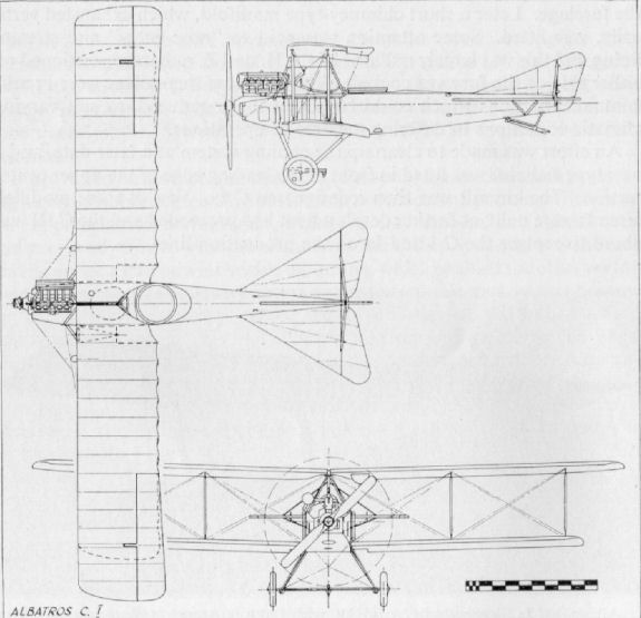
Albatros C II
Only a single example of the C II was built, very early in 1916, to assess the possibilities of the "pusher" layout; designated Gitterschwanz (lit. trellis tail) by the Germans. The C II, bearing the military serial C 27/16, was powered with the 150 h.p. Benz Bz III engine and appeared to use a complete set of C I wings and undercarriage chassis.
Only a single example of the C II was built, very early in 1916, to assess the possibilities of the "pusher" layout; designated Gitterschwanz (lit. trellis tail) by the Germans. The C II, bearing the military serial C 27/16, was powered with the 150 h.p. Benz Bz III engine and appeared to use a complete set of C I wings and undercarriage chassis.
Albatros C III
The C III succeeded the Albatros C I and Ia as an operational general-purpose aircraft, and it eventually became the most prolific of all Albatros two-seaters.
The prototype was powered with the eminently reliable Benz Bz III motor of 150 h.p., but when series production commenced the majority of C IIIs had the 160 h.p. Mercedes D III installation, although some were still lined with the Benz.
Basically this aeroplane was very similar to its C I forebear, but in a more refined and compact form. It preserved the same formula of plywood-covered, slab-sided fuselage, with slightly rounded top decking; two-spar wooden wings with fabric covering and steel tube framed control surfaces.
The C III was instantly distinguishable from the C Ia by virtue of its completely revised tail surfaces. These dispensed with the earlier aircraft's angularity and adopted the beginning of the rounded tailplane profile that was to be a hallmark of practically all subsequent Albatros C types. The triangular vertical fin was retained, but a rounded rudder was now fitted. The pattern for these tail surfaces had already been used by Albatros on their B III two-seater, which had been used originally for reconnaissance work. The use of the near-identical empennage on the C III was successful, bestowing more sensitive longitudinal control than on the docile C I. This facilitated more immediate response in the evasive combat manoeuvres which were becoming so necessary with the increase of aerial activity on both sides.
It was during the winter of 1916 that the C III came to the Fl. Abt. on the Western Front, and began to command no little respect from Allied pilots who met it in combat. It was not an easy machine to shoot down, partly due to the ability of its wooden-shelled fuselage to absorb considerable punishment before any real structural weakness occurred. After some months service it was found that performance did not suffer unduly if a synchronised forward-firing machine-gun was fitted for use by the pilot, in addition to the observer's gun. As such, it was probably the first "two-gun" operational C type and was quite a formidable opponent except when, due to the vicissitudes of its rudimentary interrupter gear, it managed to shoot off its own propeller. However, this was a difficulty with which all pilots of tractor aircraft, regardless of nationality, had to contend.
Although mostly used for reconnaissance patrols, the C III sometimes carried a small bomb load, sufficient to constitute a certain nuisance value lack of an accurate sighting device precluded it becoming more than that. It was also used for co-operation with artillery batteries (Fl. Abt. (A)) when the necessary radio equipment was installed.
TECHNICAL DATA
Purpose: Two-seat general purpose.
Manufacturers:
Albatros Flugzeug-Werke G.m.b.H.
Ostdeutsche Albatros Werke (O.A.W.).
Deutsche Flugzeug-Werke A.G. (D.F.W.).
Hanscatische Flugzeug-Werke (Hansa).
Linke-Hofmann Werke (Li).
Luft-Verkehrs Gesellschaft (L.V.G.)
Siemens-Schuckert Werke (S.S.W.).
Power Plant: 150 h.p. Benz Bz III or 160 h.p. Mercedes D III.
Dimensions: Span, 11.690 m. (38 ft. 4 1/4 in). Length, 8 000 m. (26 ft. 3 in.). Height, 3.100 (D III engine) (10 ft. 2 in.); 3.070 (BzIII engine) (10 ft. 0 3/4 in.). Wing area, 36 91 sq.m. (399 sq.ft.).
Weights: Empty, 851 kg. (1,872.2 lb.). Loaded, 1,353 kg. (2,976.6 lb.).
Performance: Maximum speed, 140 km.hr. (87 5 m.p.h.). Initial climb, 1,000 m. (3,280 ft.) in 9 min. Ceiling, 11,000 ft. Duration, 4 hr.
Armament: Parabellum gun for observer initially, fixed forward-firing gun for pilot later. Light bomb load (200-lb. - stowage drum provided inside fuselage on centre of gravity, between cockpits.
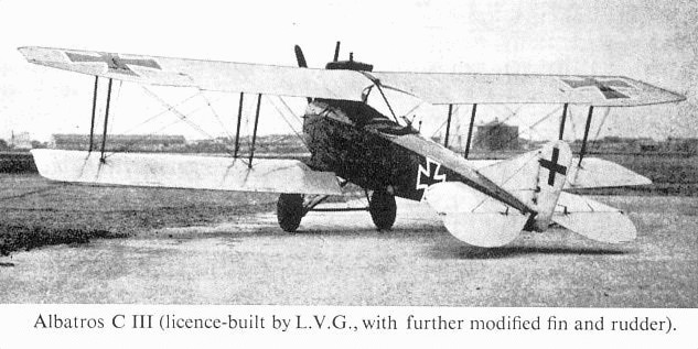
Albatros C III 15270/ 17 (licence-built by L.V.G.,with further modified fin and rudder) tested at Adlershof.
Albatros C IV
Only a single aircraft of this type was built, C 850/15, powered with the 160 h.p. Mercedes D III engine and utilising C III fuselage, tail assembly and undercarriage chassis, complete with claw brake. The pilot sat in the rear cockpit, and there was an extremely spacious front cockpit underneath the top wing. The deep-sectioned wings, with their special single-bay interplane struts which dispensed with incidence bracing, were built to scale for the G II and G III types which came later. Aircraft in background above are B III (right) and C I (left).
Only a single aircraft of this type was built, C 850/15, powered with the 160 h.p. Mercedes D III engine and utilising C III fuselage, tail assembly and undercarriage chassis, complete with claw brake. The pilot sat in the rear cockpit, and there was an extremely spacious front cockpit underneath the top wing. The deep-sectioned wings, with their special single-bay interplane struts which dispensed with incidence bracing, were built to scale for the G II and G III types which came later. Aircraft in background above are B III (right) and C I (left).
Albatros C V/16 and C V/17
With the advent of a more powerful engine from the Mercedes stable in 1916 (the 220 h.p. D IV) Albatros Werke set about producing a successor to heir C III design. The engine itself was a somewhat revolutionary "straight eight", i.e. an eight-cylinder in-line engine with water-cooling arrangements. It was practically the earlier 160 h.p. D III but for the addition of two more cylinders and a reduction gearing to bring down the airscrew revolutions to 910 r.p.m. from a crankshaft speed of 1,400 r.p.m. To accommodate the added length and weight of this power plant a complete re-design of the airframe was necessary and not merely a few modifications as had been the case with the C I/C III variants.
In the re-design, advantage was taken of the raised thrust-line (resulting from the gearbox on the forward end of the crankshaft) to improve the nose entry. The engine was almost entirely enclosed with easily-removed metal panels, only the water header tank remaining exposed. The cleaning up of the nose section was completed by the use of a large blunt spinner on the airscrew. The remainder of the fuselage was of the characteristic slab-sided, wood-and-ply construction and of roomier proportions than on the C I and C III. As before, it tapered to a horizontal knife-edge, but now a curved vertical fin was built integral with the fuselage and likewise plywood covered: the near semicircular tailplane was of wooden construction and also ply-covered. For the first time, a balanced rudder appeared on an operational Albatros two-seater, but followed previous practice in still being of steel tube framing with fabric covering. The elevator continued the same method, but was now a one-piece control and not divided as before; it was still not balanced.
The wings, although of greater span, followed the same trend as those of the C III, retaining the unbalanced ailerons of inverse taper and angular rake at the tips: the chord of the lower wing was increased to the same dimension as that of the upper. The main ribs were interspaced with false ribs (literally little more than wooden (ash) strips) extending as far as the rear spar.
Yet a third location was found for the radiators as compared with the CI and C III types. These were of the usually described "ear" type, located on the fuselage sides just above the leading edge of the lower wing. To a certain extent they detracted from the cleanliness that had been obtained in the nose section.
An orthodox streamline steel tube undercarriage, with claw-type brake, was still used, as was the externally sprung tailskid mounted on an inverted pyramid of struts.
Such, then, was the Albatros C V of 1916, or C V/16 as it was known to the makers. Due to the increase in weight and size, it proved a somewhat cumbersome machine to fly, and its unbalanced controls demanded no little man-power from its pilots. It was apparent to the Albatros design team that improvement of flight characteristics could be made, and a modified version was put in hand; this was known only by the factory designation of C V/17.
The first concession to cleanliness was the fitting of a revised exhaust manifold exhausting sideways instead of vertically. Fitting an aerofoil-shaped radiator in the centre-section of the upper wing immediately obviated the considerable drag of the earlier "ear" radiators.' A further refinement was the fitting of a completely new lower wing with an elliptical tip profile, and substitution in the upper wing of ailerons of reverse taper which incorporated large inset (rectangular) balance portions. Finally, attention was directed to the tail assembly: the elevator was modified to include triangular balance portions at the tips, and the re-designed tailskid was internally sprung.
With the balancing of all the flight controls, sensitivity was considerably increased, and the general cleaning-up resulted in a slight all-round increase in performance. In both C V/16 and C V/17 a forward-firing synchronized machine-gun was a standard fitment in addition to the observer's Parabellum gun on a rotatable mounting. Bombs and radio gear were also carried according to the particular duty. Here, then, was a good, solid, comfortable aeroplane; unfortunately its good qualities were marred by the vagaries of its eight-cylinder power plant. This, as so often happens in time of war, had been speeded into production before all the faults had been eliminated, and it lacked the reliability of its 160 h.p. DIII predecessor. The main fault was the extreme length of the crankshaft, necessitated by the eight "in-line" cylinder block, which rendered this component extremely prone to failure. Eventually, after production of no more than 424 examples, manufacture of this engine was discontinued, whereupon production of the Albatros C V terminated also.
TECHNICAL DATA
Purpose: Two-seat general purpose (reconnaissance, artillery co-op, bombing).
Manufacturer: Albatros Werke G.m.b.H.
Power Plant: 220 h.p. Mercedes D IV 8 cylinder in-line water cooled.
Dimensions: Span: C V/16, 12.780 m. (41 ft. 11 1/4 in.); C V/17, 12.620 m. (41 ft. 5 in.). Length, 8.950 m. (29 ft. 4 3/8 in.). Height, 4.500 m. (14 ft. 9 1/4 in.). Wing area, 43.4 sq. m. (468.72 sq.ft.).
Weights: Empty, 1,024-1,069 kg. (2,253-2,352 lb.) difference representing cooling water for radiator. Loaded, 1,585 kg. (2,387 lb.).
Performance:Maximum speed, 170 km.hr. ( 106.25 m.p.h.). Initial climb, 1,000 m. (3,280 ft.) in 8 min. Duration, 3 hr. 15 min.
Armament: Parabellum gun for observer and fixed forward-firing Spandau for pilot.
Albatros C V Experimental
This aircraft was a purely experimental variant of a standard C V/16 fitted with I struts to assess any advantage this type of interplane bracing might have to offer. The engine was the straight-eight-cylindered 220 h.p. Mercedes D IV of the standard machine. Span, 12.78 m. (41 ft. 11 1/4 in.). Length, 8.95 m. (29 ft. 4 3/8 in.).
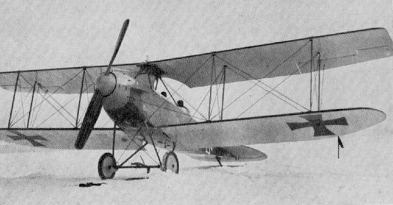
Albatros C V/17, with curved lower wing and balanced control surfaces.

Albatros C V Experimental
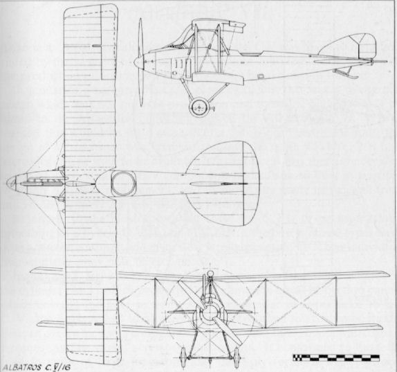
Albatros C.V/16
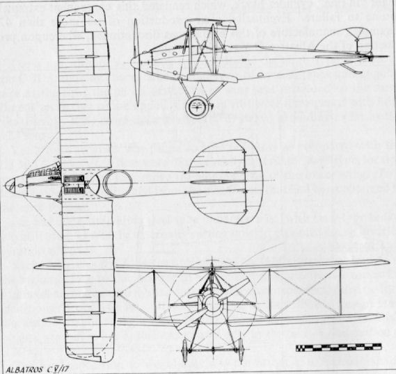
Albatros C.V/17
Albatros C VI
The Albatros C VI was virtually a C III airframe with strengthened engine bearers to take the 180 h.p. Argus As III engine. Dimensions differed fractionally from the C III, and this machine was a little lighter and slightly faster. Production was limited. Span, 11.7 m. (38 ft. 4 3/4 in.). Length, 79 m. (25 ft. 11 1/8 in.). Height, 3.2 m. (10 ft. 6 in.). Weights: Empty, 830 kg. (1,826 lb.). Loaded, 1,343 kg. (2,954 lb.). Speed, 145 km.hr. (90.625 m.p.h.). Climb, 3,000 m. (9,840 ft.) in 35 min. Duration, 4.5 hr.
The Albatros C VI was virtually a C III airframe with strengthened engine bearers to take the 180 h.p. Argus As III engine. Dimensions differed fractionally from the C III, and this machine was a little lighter and slightly faster. Production was limited. Span, 11.7 m. (38 ft. 4 3/4 in.). Length, 79 m. (25 ft. 11 1/8 in.). Height, 3.2 m. (10 ft. 6 in.). Weights: Empty, 830 kg. (1,826 lb.). Loaded, 1,343 kg. (2,954 lb.). Speed, 145 km.hr. (90.625 m.p.h.). Climb, 3,000 m. (9,840 ft.) in 35 min. Duration, 4.5 hr.
Albatros C VII
As soon as Albatros realised production of the C V was likely to be abbreviated by the vagaries of its engine, immediate consideration was given to the production of a successor to obviate any breakdown of output.
In numerical sequence the C VI came next, but this was a retrograde design which was not put into production. Thence followed the Albatros C VII. It was realised this would be little more than a "stop-gap" aeroplane until the design of a two-seater was finalised utilising the more powerful 260 h.p. Mercedes engine soon to be available in quantity. It was therefore decided to use as many standard C V components and sub-assemblies as possible to ensure a speedy replacement, and recourse was made to the well-tried and wholly reliable 200 h.p. Benz Bz IV engine.
Reference to the illustrations will show the C VII to be superficially something of a hybrid C V/16 and C V/17. In the past all these types have been apt to be confused and invariably wrongly captioned. Their individual characteristics may now be recognised.
In fact, the C VII was immediately distinguishable from the C V types by cylinder block, which protruded well above the metal inspection panels which covered the nose section. Although similar in appearance to the C.V, the fuselage had to be considerably re-worked to accommodate the Benz engine (which was considerably shorter than the 220 h.p. Mercedes it replaced) and its varied accessory components. It conformed to the well-tried formula of basic longerons and multi-ply formers, with plywood covering and no internal bracing. Once again the radiators were placed on the fuselage sides, just above the leading-edge of the lower wing.
The usual two-bay cable-braced wings were a mixture of both C V series machines, the upper wing being of the 1917 type including ailerons, but without the centre-section radiator; the lower wing reverting to the angular raked tip of the C V/16. The complete tail assembly was identical to that of the earlier machines, as was the complete undercarriage chassis. The tailskid was of the same internally-sprung arrangement as that of the C V/17, and the complete cockpit controls of that aircraft were also retained.
As so often happens with a "stop-gap" machine, the C VII proved to be an extremely successful and well-liked aeroplane. It was reported to be comfortable and not tiring to fly, and landed without undue tendency to "balloon", as was often the case with two-seaters of comparatively light wing loading. It was widely used by the Fl. Abt. and Fl. Abt. (A) Flights on reconnaissance and artillery observation patrols towards the end of 1916, and as many as 350 were serving on all Fronts by February 1917.
TECHNICAL DATA
Purpose: Two-seat long distance and artillery observation.
Manufacturers:
Albatros Werke G.m.b.H. (Alb.).
Ostdeutsche Albatros Werke (O.A.W.).
Bayerische Flugzeug Werke (Bay.).
Power Plant: 200 h.p. Benz Bz IV 6 cylinder in-line, water cooled.
Dimensions: Span, 12.780 m. (41 ft. 11 1/4 in.). Length, 8.700 m. (28 ft. 6 1/2 in.). Height, 3.600 m. (11 ft. 9 3/4 in.). Wing area, 43.4 sq.m. (468.72 sq.ft.).
Weights: Empty, 989 kg. (2,176 lb.). Loaded, 1,550 kg. (3,410 lb.).
Performance: Maximum speed, 170 km.hr. (106.25 m.p.h.). Initial climb, 1,000 m. (3,260 ft.) in 8 min. Ceiling, 5,000 m. (16,400 ft.). Duration, 3 hr. 20 min.
Armament: Two machine-guns. One fixed, firing forward for pilot. One free-firing for observer. Light bomb load carried occasionally, according to tactical requirement.
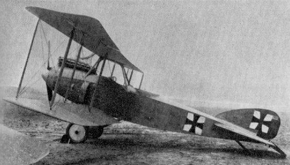
Albatros C VII
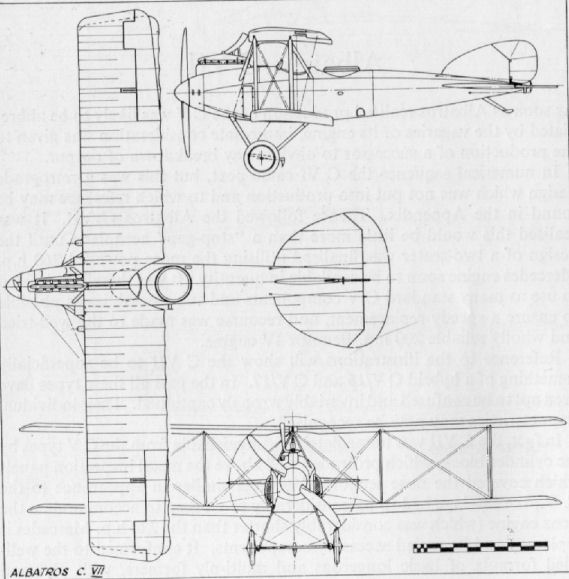
Albatros D I and D II
The year 1916 saw the introduction of the Albatros D I in a successful endeavour to wrest from the Allies the supremacy their Nieuports and D.H. 2s had now gained from the Fokker monoplanes. They began operations with the newly-formed Jagdstaffeln (of which Oswald Boelcke's Jasta 2 undoubtedly became the most well known). These units were equipped from the autumn of 1916. The new aircraft gradually replaced the older Halberstadt D II and IIIs and Fokker D II and IIIs as they became available, and usually they went to pilots in order of seniority.
Designed by Messrs. Thelen and Schubert, this sleek, streamlined, semi-monocoque aircraft was looked upon at the time as being somewhat unorthodox, as indeed it was. Although the wing structure adhered to former practice, the fuselage was certainly of a revolutionary nature, differing so radically from the fabric-covered, braced box-girder type fuselage structures then in almost universal use. In employing the 150 h.p. Benz Bz III or 160 h.p. Mercedes D III engine it was the most powerful single seat fighting scout yet brought into use in the German Air Force, and this additional power enabled it to carry the extra load of twin fixed Spandau machine-guns without loss of performance. Such armament had previously been tried on the Fokker and Halberstadt D types, but due to their lower power, performance deteriorated considerably with the added weight of the second gun, so they continued to operate with a single gun, sacrificing fire-power for performance.
Although, due to its heavier wing loading, the Albatros D I had not the manoeuvrability of the majority of its single-seat adversaries, it possessed the speed to attack when to advantage and, more important, to break off combat when expedient. It also had the fire-power of its twin machine-guns, with which to destroy much more quickly.
Albatros had, of course, pioneered wooden fuselage construction, but the D I was the first attempt to strike a compromise between the usual slab-side and the extremely expensive true monocoque structure. How successful this compromise was may be gauged from the subsequent lineage of Albatros D type machines. The fuselage structure consisted basically of 3/8 in. thick ply formers and six spruce longerons, to which was pinned and screwed the outer covering of three-ply. In section it varied from a circular nose entry to a horizontal knife edge aft, with the middle cross-sections being of flat-sided oval shape. The engine was cleanly installed in the nose, with quickly detachable metal panels adjacent to the cylinder block and immediately aft of the large bulbous spinner, to facilitate servicing. Exhaust manifolds varied in that they sometimes were of the funnel type ejecting vertically and sometimes of the horizontal type exhausting sideways to starboard.
The clean contours of the fuselage were spoilt to a certain extent by the box-shaped Windhoff radiators mounted on the sides between the wings. Built into the rear fuselage were the pleasingly curved tail surfaces. The fixed surfaces were of wood and the upper and lower fin - which supported the ash tailskid - were covered in plywood skin. The tailplane was fabric-covered. The control surfaces were of welded steel-tube framework with fabric covering, and small triangular balance portions were incorporated in both the one-piece elevator and the rudder.
The wings were a fabric-covered wooden structure, following the usual Albatros formula of two box-spars positioned well forward and with a wire trailing edge; they were rectangular in shape, with just the smallest suggestion of rake at the tips. Ribs were of three-ply fretted with lightening holes and narrowly flanged with spruce. Ailerons were of steel-tube framework with a slight inverse taper, and were actuated by a crank arm located at mid-span. The top wing was built in one piece and secured to the trestle-type centre-section cabane by eye bolts which could be located in five different positions enabling the stagger to be adjusted from 0 to 12 cm. (approx. 4 3/4 in.).
A conventional streamlined steel-tube vee-type undercarriage chassis was fitted to sockets mounted on the fuselage; a single spreader bar behind the axle tied the vees together, and the wheels were sprung with rubber shock cord.
Throughout the winter of 1916-17 the Albatros D I and D II operated in increasing numbers, and with their twin machine-gun armament reaped a grim harvest among the ill-armed Allied B.E.2c reconnaissance planes. Although they completely outclassed the British D.H. 2 single-seat fighting scout in speed and armament, they did not have it all their own way with this opponent, which, due to its superior manoeuvrability, was often agile enough to elude their guns.
Although the D I was a satisfactory and pleasant aircraft to fly, its main shortcoming in combat was that the top wing rather obscured the pilot's forward and upward field of vision. It was decided, therefore, to reduce the gap and re-position the upper wing closer to the fuselage. The outcome of this was the Albatros D II. The large semicircular centre-section cut-out was retained and the pilot was enabled to see over the top wing more easily and with a much-improved field of vision. The method of reducing the gap was to dispense with the trestle-type centre-section cabane and substitute two sets of outsplayed "N" centre-section struts. This achieved the desired suit, and it was additionally found that with the struts splayed out the pilot's forward view under the wing was materially improved too. Slight alteration was also necessary to the length of the streamlined steel-tube interplane struts. Apart from these modifications, the rest of the machine was virtually the same as the D I.
At a later date an attempt was made to clean up and improve the D II by disposing of the cumbersome radiator system and installing an aerofoil-shaped Teeves and Braun radiator in the starboard side of the upper wing centre-section. In this ultimate version the D II certainly presented a neat and clean appearance.
Many famous German pilots flew the D I and D II Albatroses, and initially they operated in mixed flights, together with Halberstadt and Fokker D IIs and IIIs, until sufficient Albatroses were available for a Jasta to standardise on the type. The first patrol to include the new Albatros scouts was led by Oswald Boelcke, who commanded Jasta 2, when a sortie was made on 17th September 1916. A few weeks later, on 28th October, Boelcke, whose victory score then stood at forty, crashed to his death when his Albatros was struck by that of Erwin Bohme as both converged in a diving attack on two D.H. 2s of No. 24 Squadron, R.F.C. The death of this redoubtable and chivalrous airman was soon avenged by none other than Manfred von Richthofen, who later went on to double Boelcke's score before he was shot down in April 1918. He was not destined, however, to become noted for his chivalry. One of the D IIs flown by Richthofen in Jasta 2 was 491/16, and he scored his first victory in this type on 17th September 1916. Manfred von Richthofen eventually became leader of Jasta 2, and on 23rd November 1916 he shot down Major Lanoe G. Hawker, V.C., in a D.H. 2 after a long individual combat, his eleventh aerial victory. It was generally supposed that the superior performance of von Richthofen's Albatros D II was the greatest factor in enabling him to overcome such an experienced pilot as Hawker. No less a pilot than Major J. B. McCudden, V.C., was able to testify to the fire-power of the Albatros when, on return from a patrol on 9th November 1916, he discovered twenty-four hits on his D.H. 2 after his first encounter with the type. Never again were so many hits registered on a machine of his.
Prinz Friedrich Karl of Prussia was another redoubtable exponent of the D I and D II. He was actually C.O. of a Fl. Abt. unit, but kept a personal Albatros D I ready for his use with the nearby Jasta 2, with which Staffel he used to hunt when he was able to get away from his reconnaissance duties. He was eventually shot down, however, in a skull-inscribed D I of Jasta 2 on 21st March 1917.
Although it has not been possible to ascertain how many were built, records show that in November 1916 50 D Is and 28 D IIs were serving at the Front; January 1917 saw 39 D Is in use and as many as 214 D IIs. By November 1917 the figures were reduced to 9 D Is and 11 D IIs, by which time the D III and D V were very much in prominence.
TECHNICAL DATA
Description: Single-seat fighting scout.
Manufacturers:
Albatros Werke G.m.b.H. (Alb.).
Luft-Verkehrs Gesellschaft (Lvg). (1)
Oesterreichische Flugzeugfabrik A.G. (Oeffag) (1) (built for Austro-Hungarian forces and powered with 185 h.p. Austro-Daimler).
Power Plant: One 150 h.p. Benz Bz III or 160 h.p. Mercedes D III 6 cylinder inline water-cooled engine, D I: 160 h.p. Mercedes D III only D II.
Dimensions: Span, 8.50 m. (27 ft. 10 3/4 in.). Length, 7.40 m. (24 ft. 3 1/8 in.). Height. 2.95 m. (9 ft. 6 3/8 in.), D I; 2.641 m. (8 ft. 6 3/8 in), D II. Wing area, 22.9 sq.m. (247 sq.ft.), D I; 24.5 sq.m. (264 sq.ft.), D II.
Weights: Empty, 647 kg. (1,423 lb.), D I; 637 kg. (1,401 lb.), D II. Loaded, 898 kg. (1,976 lb.), D I; 888 kg. (1,954 lb.), D II.
Performance: Maximum speed, 175 km.hr. (109.4 m.p.h.). Initial climb, 1,000 m. (3,280 ft.) in 6 min. (5 min. for D II). Ceiling, 17,000 ft. Duration, 1 1/2 hr.
Armament: Two fixed Spandau machine-guns synchronised to fire through airscrew.
(1) D II only.

Albatros D IIs of Jasta 14.

Albatros D.I
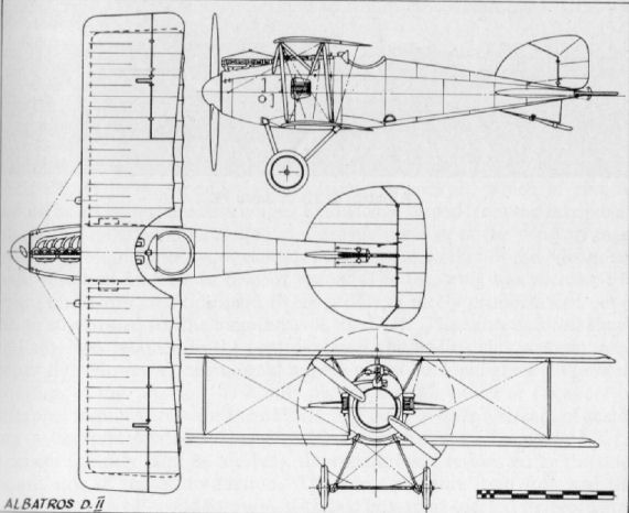
Albatros D.II
Albatros D III
Almost before the Albatros D Is and lis were well into production, Robert Thelen had set about ensuring a successor which adopted some of the advantages of the French Nieuport Scout design. Several of these had been captured and thoroughly type-tested by Idflieg (Inspectorate of Army Air Corps) to assess which of their characteristics could best be adapted to German requirements.
By increasing the compression ratio of the standard Mercedes D III it was possible to uprate the basic 160 h.p. to about 170 h.p., but this did not give much scope for an improvement in performance. Additional armament on such a marginal power increase would doubtless have affected performance adversely. The designers therefore decided to concentrate their efforts in improving visibility from the cockpit, which in combat would be an immediate advantage. Knowledge gained from the assessment of the Nieuport Scouts resulted in a drastic revision of the wing arrangement. A sesquiplane layout was adopted, similar to that of the Nieuports, with resultant increase in field of vision. The top wing was increased in span, and more attention paid to tip profile, a nicely proportioned curve being substituted for the angularity of the D II. The same aerofoil-shape radiator was retained in the centre-section and at first this was mounted centrally. However, operational experience soon highlighted the shortcomings of this position, as it only needed a single bullet or fragment of shrapnel to puncture it for the unfortunate pilot to have a stream of scalding water precipitated in his face by the slipstream. To obviate such chances (quickly fatal in combat), the radiator was re-located on the starboard side of the centre-section. The wing structure itself followed the usual Albatros all-wood formula, with two box-spars located well forward, but with the front spar connected to the leading edge with a ply capping strip. A wire trailing edge perpetuated the characteristic scalloped effect. The steel tube-framed ailerons were of greater inverse taper than on the earlier Albatros scouts, although their operation remained unchanged, with a mid-span crank lever connected to control wires running through the lower wing.
In the lower wing the chord was drastically reduced and the whole structure built on a single spar, near-identical Nieuport practice in all but actual profile. This wing arrangement necessitated a revision of the interplane bracing, and streamlined steel-tube vees were used for this purpose.
The remainder of the airframe: fuselage, empennage, undercarriage, etc., were all standard D II assemblies, with small detail modifications where necessary, i.e. lower-wing attachment points, centre-section strut attachment, to suit the D III requirements. At a later date many Albatros D IIIs were fitted with the much rounder D V-type rudder, and such aircraft are often wrongly identified. A certain means of D III identification, apart from the flattened fuselage sides, is by the vertical trailing edge of the underfill.
As soon as the D III began to operate over the lines in the early months of 1917 it was quickly dubbed "vee strutter" by the opposing R.F.C. pilots, and as its numbers steadily increased, so it appeared with greater frequency upon Allied combat reports. Undoubtedly the spring of 1917 was the heyday of the German air service, at least as far as the single-seater units were concerned, and April of that year went down in the British annals as "Bloody April". The main victims of the Albatroses at this period were the poorly armed reconnaissance B.E. 2cs which the R.F.C. possessed in such relatively large quantity. Such machines were little more than sitting targets for the fleet, well-armed Jastas, and many German airmen were soon well on their way to becoming recognised as "aces". The legendary Baron Manfred von Richthofen, already with a double-figure victory score at the time he shot down Hawker in November 1916, rapidly added to his score when flying his scarlet Albatros D III (789/17) during this early part of 1917.
By this time Jagdstaffeln Nos. I 37 had been formed and were operating and hunting in large numbers, but they began to meet stiller resistance with the introduction of the Sopwith Triplane and Spad S VII by the Allies. With the appearance of the S.E. 5 and Sopwith Camel a little later, the superiority of the Albatros D III was ended. Lt. Osterkamp. a pilot with the German Marine Wing, who was eventually victor in some thirty-two aerial combats, reported: "The Albatros D III is no longer sufficient, the Camel and Spad are its superiors."
Records show that the number of Albatros D IIIs in Front Line service during 1917 were: January, 13; March, 137; May, 327; July, 303; September. 385; November, 446. These figures, of course, are not cumulative, as, even allowing for wastage, each month's total would still include a sizeable proportion of the previous month's. However, they do provide an idea of the numbers being produced. The Albatros D III was superseded in the summer of 1917 by the Albatros D V.
TECHNICAL DATA
Purpose: Single-seat Fighting Scout.
Manufacturers:
Albatros Werke G.m.b.H. (Alb.).
Ostdeutsche Albatros Werke, Schneidemuhl (O.A.W.).
Oesterreichische Flugzeugfabrik A.G. (Oeffag). (For Austro-Hungarian forces, with Austro-Daimler engine.)
Power Plant: 160 h.p. Mercedes D IIIa 6 cylinder in-line water cooled - up-rated to 170-175 h.p. by increased compression ratio.
Dimensions: Span, 905 m. (29 ft. 8 1/4 in.). Length, 7.33 m. (24 ft. 0 5/8 in.). Height, 2.98 m. (9 ft. 9 1/4 in.). Wing area, 20.5 sq.m. (221 sq.ft.).
Weights: Empty, 661 k.g. with cooling water (1,454 lb.). Loaded, 886 kg. (1,949 lb.).
Performance: Maximum speed, 165 km.hr. (108 m.p.h.). Initial climb, 1,000 m. (3,280 ft.) in 4 min. Ceiling, 18,000 ft. Duration, 2 hr.
Armament: Two fixed Spandau machine-guns synchronised to fire through airscrew.

Albatros D III flown by Werner Voss in Jasta 5.
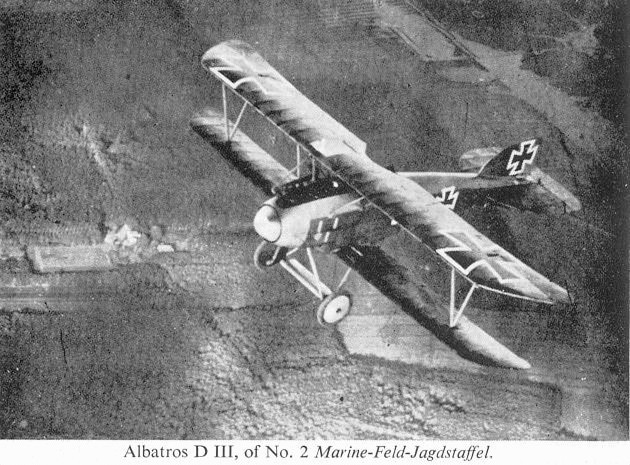
Albatros D III, of No. 2 Marine-Feld-Jagdstaffel.

Photographed in the summer of 1917, this Albatros D III belonged to No 2 Marlne-Feld-Jagdstaffel.
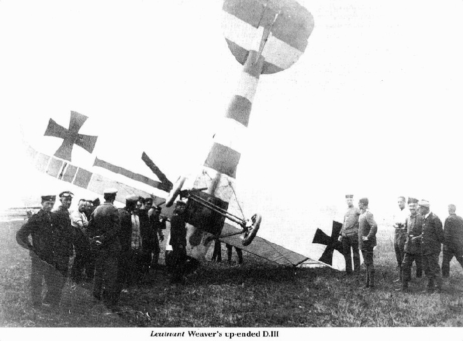
Leutnant Weaver's Albatros D III of Jasta 26 which overturned on landing.
Albatros G I
Built at Schneidemuhl factory to designs of Konstr. Grohmann, a first flight was made on 31st January 1916. Apart from the fact that the aircraft was completely unsatisfactory, no further information is available.
The aircraft was powered with four 100 h.p. Mercedes D I engines and scaled a loaded weight of 4,319 kg. (9,502 lb.).
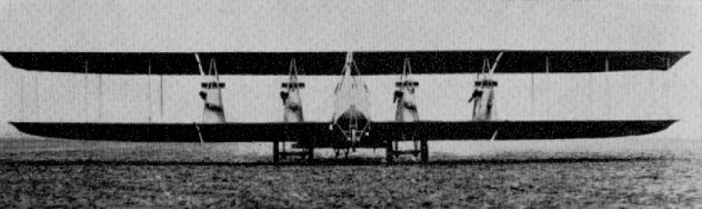
Albatros G I
Albatros G II
Designed as a medium bomber, the G II featured a thick high-lift wing section. The bracing was reduced to a single-bay format and the rigid "X" members of the interplane struts eliminated the need for incidence wires. Only a single prototype was built, in 1916, before an improved model, the G III, was introduced. Apart from the nose wheels, the G II presented a neat appearance for a twin of 1916. It was powered with twin 150 h.p. Benz III engines, which were neatly installed and fitted with spinnered pusher airscrews.
Albatros G III
The G III appeared at the end of 1916, and was built in small numbers. It has not been established that it was flown on the Western Front, but some entered service in Macedonia. With its ply-skinned fuselage and fabric-covered wings, the aircraft followed established Albatros constructional practice. Engines, two 220 h.p. Benz IVa. Span, 18.0 m. (59 ft. 0 3/4 in.). Length, 11.895 m. (39 ft. 0 3/8 in.). Area, 79 sq.m. (853.2 sq.ft.). Weights: Empty, 2,064 kg. (4,541 lb.). Loaded, 3,150 kg. (6,930 lb.). Speed, 150 km.hr. (93.75 m.p.h.). Climb, 1,000 m. (3,280 ft.) in 9 min., 2,000 m. (6,560 ft.) in 25 min. Duration, 4 hr.
Albatros W 2
Intended for armed patrol duties, the W 2 utilised the basic fuselage and wing cellule of the C III, although the centre-section strut arrangement and installation of the 160 h.p. Mercedes D III engine differed somewhat. The considerable increase in upper fin area is also noticeable. Most notable feature of this aircraft was the extremely clean and simple float chassis, but it is doubtful if it was sufficiently rugged. Only a single example (Marine No. 450) was supplied, in June 1916, armed with manually operated Parabellum machine-gun in rear cockpit.
Intended for armed patrol duties, the W 2 utilised the basic fuselage and wing cellule of the C III, although the centre-section strut arrangement and installation of the 160 h.p. Mercedes D III engine differed somewhat. The considerable increase in upper fin area is also noticeable. Most notable feature of this aircraft was the extremely clean and simple float chassis, but it is doubtful if it was sufficiently rugged. Only a single example (Marine No. 450) was supplied, in June 1916, armed with manually operated Parabellum machine-gun in rear cockpit.

Albatros W 2
Albatros W 3
A single example of the W 3 was built (Marine No. 527) and supplied to the German Navy in July 1916. It was designed as a torpedo attack machine and developed into W 5. Engines, two 150 h.p. Benz III. Span, 22.7 m. (74 ft. 5 7/8 in.). Length, 13.1 m . (42 ft. 11 7/8 in.). Speed, 133 km.hr. (83.125 m.p.h.). Armament, torpedo and two manually operated machine-guns.
Albatros W 5
Although a derivative of the W 3, this aircraft differed considerably in detail. Wings were swept and four ailerons fitted, and the vertical surfaces were of more triangular shape. Much larger floats were carried. The nose and tail of the torpedo, which was stowed well in the belly of the aircraft, may be seen in the photograph. Engine housing was modified to give improved cooling. Orthodox Albatros construction, featuring ply-covered fuselage, was used. Five machines were supplied to the Navy (Marine Nos. 845-849) between May 1917 and January 1918, by which time the ideas for use of torpedo aircraft had been abandoned. Engines, two 150 h.p. Benz. Span, 22.7 m. (74 ft. 5 7/8 in.). Length, 131 m. (42 ft. 11 7/8 in.). Height, 4.25 m. (13 ft. 11 3/8 in.). Area, 100 sq.m. (1,080 sq.ft.). Weights: Empty, 2,263 kg. (4,979 lb.). Loaded, 3,665 kg. (8,063 lb.). Speed, 133 km.hr. (83.125 m.p.h.). Climb, 1,000 m. (3,280 ft.) in 20 min. Duration, 4 hr. Armament, torpedo and two manually operated machineguns.
Albatros W 4
During 1916, as a result of the depredations of British flying-boats and seaplanes upon the North Sea Air Stations of Zeebrugge, Borkum, etc., the German Naval authorities ordered the production of single-seat seaplane fighting scouts (Jagdetnsitzer Wasser) for local station defence duties. To ensure the speedy appearance of a suitable aircraft, modification of land machines was put in hand, resulting in the appearance of the Brandenburg KDW (a seaplane version of the D I "Star Strutter" scout supplied to the Austrian air forces), the Rumpler 6BI and 6BII (a single-seat seaplane variant of the C I) and the Albatros W 4, which used many components of the Albatros D I.
These Albatros W 4s were able to remain on patrol in the vicinity of their home station for about three hours, attacking any enemy aircraft that should put in an appearance. Enemy patrol seaplanes were not too difficult to deal with, as the W 4 usually had the edge in speed and manoeuvrability, and was certainly superior in armament. The powerful and well-armed flying-boats of the R.N.A.S. Yarmouth and Felixstowe stations were, however, a much stiffer proposition, and pilots had to be possessed of a considerable degree of dash and resolution to close with these redoubtable opponents and achieve any decisive effect.
The Albatros W 4 has often been described as an "Albatros D I (or D II) on floats", whereas, in fact, it was considerably larger in overall dimensions. Certainly the D I fuselage was used as a basis, although this was modified to a degree, especially in the tail section. The same basic formula of longerons and formers with ply covering was used; the upper fin was still built integral with the fuselage and ply-covered, but it was increased in area to compensate for the under-fin, which was deleted. The tailplane was also increased in area, ply-covered and braced to the vertical fin with light-gauge steel struts. As on the D I, the one-piece balanced elevator and the rudder were of welded steel-tube framing and covered with fabric. On the earlier W 4s the box-like Windholf radiators were positioned on the fuselage sides as on the D I but later the more efficient Teeves and Braun aerofoil-shaped radiators were installed in the centre-section in an endeavour to reduce drag.
It was in the wing structure the W 4 differed from the D types, the span being increased by exactly 1 m. (3 ft. 3 3/16 in.), although the profile remained much the same, as was the constructional method of ply ribs mounted on two box-spars. The gap was much increased, and much longer and stronger centre-section struts were required. These were of streamlined section steel tube, of inverted U-shape with strengthening webs at the corners, and splayed outwards from the fuselage. Initially, ailerons of inverse taper were fitted to the upper wingtips only, but with this arrangement lateral control was on the sluggish side, so subsequent aircraft were fitted with ailerons at all four wingtips, linked with a steel-tube strut.
A variety of floats was fitted to Albatros W 4s in an endeavour to discover optimum take-off performance. Operating from their own - presumably sheltered - waters, no great degree of seaworthiness, in the accepted sense, was required. Single-stepped floats of plain rectangular cross-section, and with little fore-and-aft taper at either bows or stern, were fitted; floats with flat tops, curved top decking and twin steps were also tried. A robust steel-tube chassis supported the floats, and the spreader struts were of the same medium; all bracing wires were of stranded cable.
Increased fuel tankage (two separate tanks each of 73 litres capacity, together with 13 litres of oil) provided the considerable endurance already mentioned.
Albatros W 4s remained in service until replaced by the faster and more effective Brandenburg two-seaters. They were supplied to the German Navy in small batches over the period September 1916 to December 1917, by which time some 118 of the type had been delivered.
TECHNICAL DATA
Description: Single-seat station defence seaplane.
Manufacturers: Albatros Werke G.m.b.H. Friedrichschagen.
Power Plant: One 160 h.p. Mercedes D III 6 cylinder in-line water-cooled engine.
Dimensions: Span, 9.5 m. (31 ft. 2 in.). Length, 8.5 m. (27 ft. 10 3/4 in.). Height, 3.65 m. (11 ft. 11 3/4 in.). Wing area, 31.6 sq.m. (341 sq.ft.).
Weights: Empty, 790 kg. (1,738 lb.). Loaded, 1,070 kg. (2,354 lb.).
Performance: Maximum speed, 158-160 km.hr. (100 m.p.h.). Initial climb, 1,000 m. (3,280 ft.) in 5 min. Ceiling, 9,840 ft. Duration, 3 hr.
Armament: Two fixed Spandau machine-guns synchronised to fire through airscrew. (Sometimes only one gun fitted.)
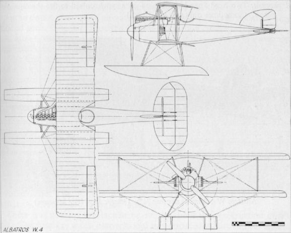
Albatros C IX
A forerunner of the CL machines, three examples only of the C IX were constructed during 1917. It was of unusual single-bay format for a two-seater, with the top wing considerably swept and the lower wing straight. The fuselage and empennage was similar in construction to that of the famous D types. It is reported that one of the C IXs was presented to Baron Manfred von Richthofen for his use behind the lines as a personal transport. Engine, 160 h.p. Mercedes D III. Span, 10.4 m. (34 ft. 1 1/2 in.). Length, 8.22 m. (26 ft. 11 7/8 in.). Height, 2.735 m. (8 ft. 11 3/4 in.). Weights: Empty, 790 kg. (1,738 lb.). Loaded, 1,150 kg. (2,530 lb.). Speed, 155 km.hr. (96.875 m.p.h.). Climb, 1,000 m. (3,280 ft.) in 5 min., 4,000 m. (13,120 ft.) in 30 min. Duration, ca. 2.5 hr.
A forerunner of the CL machines, three examples only of the C IX were constructed during 1917. It was of unusual single-bay format for a two-seater, with the top wing considerably swept and the lower wing straight. The fuselage and empennage was similar in construction to that of the famous D types. It is reported that one of the C IXs was presented to Baron Manfred von Richthofen for his use behind the lines as a personal transport. Engine, 160 h.p. Mercedes D III. Span, 10.4 m. (34 ft. 1 1/2 in.). Length, 8.22 m. (26 ft. 11 7/8 in.). Height, 2.735 m. (8 ft. 11 3/4 in.). Weights: Empty, 790 kg. (1,738 lb.). Loaded, 1,150 kg. (2,530 lb.). Speed, 155 km.hr. (96.875 m.p.h.). Climb, 1,000 m. (3,280 ft.) in 5 min., 4,000 m. (13,120 ft.) in 30 min. Duration, ca. 2.5 hr.
Albatros C VIII N
Evolved in 1917 as a night bomber, as indicated by the N suffix. A small bomb load was carried under the lower wings, but as this relatively large, three-bay machine was only fitted with the 160 h.p. Mercedes D III engine, it was grossly under-powered. It is doubtful if more than one such machine was built. Span, 16.74 m. (54 ft. 11 1/8 in.). Length, 7.34 m. (24 ft. 1 in.). Speed, 135 km.hr. (84.35 m.p.h.). Climb, 1,000 m. (3,280 ft.) in 5 min. Armament, one Spandau and one Parabellum machine-gun.
Evolved in 1917 as a night bomber, as indicated by the N suffix. A small bomb load was carried under the lower wings, but as this relatively large, three-bay machine was only fitted with the 160 h.p. Mercedes D III engine, it was grossly under-powered. It is doubtful if more than one such machine was built. Span, 16.74 m. (54 ft. 11 1/8 in.). Length, 7.34 m. (24 ft. 1 in.). Speed, 135 km.hr. (84.35 m.p.h.). Climb, 1,000 m. (3,280 ft.) in 5 min. Armament, one Spandau and one Parabellum machine-gun.
Albatros C X
The Albatros C X followed the C VII into service during 1917. The Albatros design team followed the established pattern, with modifications to provide for the much more powerful 260 h.p. Mercedes C IVa engine then becoming available. The result was an aeroplane of considerably larger proportions. Although not dissimilar, the C X was more majestic in appearance than its predecessors.
The fuselage followed the previous formula in being slab sided and plywood covered, but it was wider, deeper and longer. The additional space permitted the installation of oxygen breathing equipment in the pilot's (forward) cockpit and a comprehensive collection of radio apparatus in the rear cockpit.
Although still of two-bay cable-braced layout on two wooden box-spars, the wing structure was altered radically and was of noticeably greater span and area in an endeavour to extract the greatest ceiling from the additional engine power. The angular rake of the wingtips on the earlier machines was discontinued, and more attention was paid to a refined and aerodynamic tip profile.
To maintain sensitive lateral control despite the increased wingspan, ailerons were provided at all four wingtips, those on the upper surfaces being designed with large rectangular inset, balance portions. Once again an aerofoil-type radiator was used and mounted in the root of the starboard upper wing panel. The degree of shutter opening was easily seen and adjusted by the pilot.
There was no great alteration in the tail surfaces, which were of the same profile as the Albatros C V and C VII. The fixed fin surfaces were of wood with plywood skin, and the control surfaces of light gauge steel tube with fabric covering. The steel tube undercarriage was the same as that of the C V.
Like its forerunner, the Albatros C X was used mainly on reconnaissance and artillery work during 1917, when, by October, some 300 of the type were serving at the Front. It was built by no less than four sub-contractors.
TECHNICAL DATA
Purpose: Two-seat reconnaissance and artillery patrol.
Manufacturers:
Albatros Werke G.m.b.H.
Ostdeutsche Albatros Werke (O.A.W.).
Linke-Hofmann (Li.).
Bayerische Flugzeug Werke (Bay.).
L.F.G. (Roland) (Rol.).
Power Plant: 260 h.p. Mercedes D IVa 6 cylinder in-line, water cooled
Dimensions: Span, 14.360 m. (47 ft. 11 in.). Length, 9.150 m. (30 ft. 0 1/4 in) Height, 3 400 m. (11 ft. 1 7/8 in.). Wing area, 42.7 sq.m. (461.16 sq.ft.).
Weights: Empty, 1,050 kg. (2,310 lb.). Loaded, 1,668 kg. (3,669 lb.).
Performance: Maximum speed, 175 km.hr. (109.4 m.p.h.). Initial climb 1 000 m (3,280 ft.) in 5 min. 2,000 m. (6,560 ft.) in 11 min. Ceiling, 5,000 m. (16,400 ft.) in 55 min. Duration, 3 hr. 25 min.
Armament: Two machine-guns. One, fixed, firing forward for pilot. One, free-firing for observer. Light bomb load according to tactical requirement.
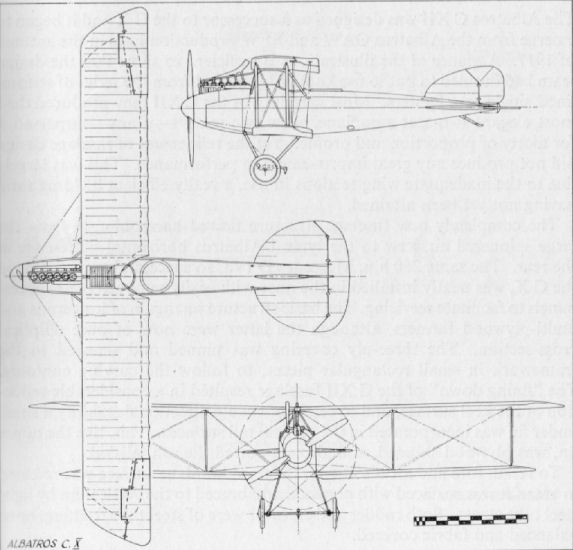
Albatros C XII
The Albatros C XII was designed as a successor to the C X and it began to emerge from the Albatros OAW and BFW production lines in the autumn of 1917. A glance at the illustrations is sufficient to show that the design team had decided to put to use knowledge gained from the series of streamlined single-seat fighters. Most certainly in the C XII they produced their most elegant two-seat aeroplane. Few two-seaters - if any - surpassed it for nicety of proportion and profile. Yet the refinement of fuselage design did not produce any great improvement in performance. This was largely due to the inadequate wing sections in use, a really efficient lift/drag ratio having not yet been attained.
The completely new fuselage structure flowed harmoniously from the large spinnered airscrew to the typical Albatros horizontal knife-edge at the rear. The same 260 h.p. Mercedes D IVa, so successful and reliable in the C X, was neatly installed in the nose with easily removed metal access panels to facilitate servicing. The basic structure was again of longerons and multi-plywood formers, although the latter were now of pure elliptical cross-section. The three-ply covering was pinned and screwed to the framework in small rectangular pieces, to follow the curving contours. The "fining down" of the C XII fuselage resulted in a considerable reduction of the keel surface, and to retain adequate directional stability a small under fin was incorporated in the vertical tail surfaces. This, like the upper fin, was plywood skinned, and also supported the ash tailskid.
To retain fore and aft sensitivity, the fixed tailplane surface was reduced in area. It was surfaced with plywood and braced to the vertical fin by light steel tube struts. Both rudder and elevator were of steel tube framing, horn balanced and fabric covered.
The wings were almost identical to those of the earlier C X and of the same wooden construction based on two box spars, the front spar being in close proximity to the leading edge and the rear spar at approximately mid-chord. Ailerons, again at all four wingtips, were of steel tube framing, aerodynamically balanced and hinged to a false spar. The aerofoil-shaped radiator mounted in the starboard centre-section was retained, as was the large centre-section cut-out.
Due to the revision of the fuselage, alteration of the undercarriage became necessary, the forward struts of which had to be lengthened considerably. Otherwise the chassis was very much the same, with streamlined steel tube vees, the usual elastic cord shock absorbers and the inevitable claw brake in the centre of the axle.
The C XII came into quite widespread service on the Western Front With the Fl. Abt. and Fl. Abt. (A) Flights during 1918, and remained in operation until the cessation of hostilities.
TECHNICAL DATA
Purpose: Two-seat reconnaissance and general purposes.
Manufacturers:
Albatros Werke G.m.b.H. (Alb.).
Ostdeutsche Albatros Werke (O.A.W.).
Bayerische Flugzeug Werke (Bay.).
Linke-Hofmann Werke (Li.). Possibly.
Power Plant: 260 h.p. Mercedes D IVa. 6 cylinder in-line, water cooled.
Dimensions: Span, 14.370 m. (47 ft. 1 7/8 in.); 14.24 m. (O.A.W.) (46 ft. ft. 6 3/4 in.). Length. 8.850 m. (29 ft. 0 3/8 in.). Height, 3.250 m. (10 ft. 7/8 in.). Wing area, 42.7 sq.m. (461.16 sq.ft.).
Weights: Empty, 1,021 kg. (2,246 lb.). Loaded, 1,639 kg. (3.606 lb. I.
Performance: Maximum speed, 175 km.hr. (109.4 m.p.h.). Initial climb, 1,000 m. (3,280 ft.) in 5 min. Ceiling, 5,000 m. (16,400 ft.). Duration, 3 hr. 15 in.
Armament: One fixed gun firing forward for pilot. One free-firing machine-gun for observer. Light bomb loads carried on external racks as tactical demand arose.
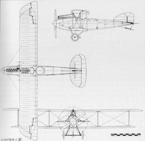
Albatros C XIII
Built in 1917, the C XIII was an endeavour to develop quickly a CL aircraft from the D Va. Only one was built and, as may be seen, it was little more than an enlarged version of the D Va. Certainly it was an elegant two-seater. Engine, 160 h.p. Mercedes D III. Span, 100 m. (32 ft. 9 3/4 in.). Length, 7.8 m. (25 ft. 7 1/8 in.). Height, 2.71 m. (8 ft. 10 3/4 in.). Weights: Empty, 700 kg. (1,540 lb.). Loaded, 1,060 kg. (2,332 lb.). Speed, 165 km.hr. (103.12 m.p.h.). Climb, 1,000 m. (3,280 ft.) in 4 min., 5,000 m. (16,400 ft.) in 47 min. Duration, 2.5 hr. Armament, one Spandau and one Parabellum machine-gun.
Built in 1917, the C XIII was an endeavour to develop quickly a CL aircraft from the D Va. Only one was built and, as may be seen, it was little more than an enlarged version of the D Va. Certainly it was an elegant two-seater. Engine, 160 h.p. Mercedes D III. Span, 100 m. (32 ft. 9 3/4 in.). Length, 7.8 m. (25 ft. 7 1/8 in.). Height, 2.71 m. (8 ft. 10 3/4 in.). Weights: Empty, 700 kg. (1,540 lb.). Loaded, 1,060 kg. (2,332 lb.). Speed, 165 km.hr. (103.12 m.p.h.). Climb, 1,000 m. (3,280 ft.) in 4 min., 5,000 m. (16,400 ft.) in 47 min. Duration, 2.5 hr. Armament, one Spandau and one Parabellum machine-gun.
Albatros D IV
The Albatros D IV was something of a hybrid, having a partial D II wing cellule and a D Va fuselage. It was powered with an experimental, specially geared, version of the standard 160 h.p. Mercedes D III, which enabled the engine to be completely buried in the nose. No guns were fitted and as there was no significant increase in performance the D IV remained no more than a prototype mainly due to difficulties with the motor. Span, 9.05 m. (29 ft. 8 3/4 in.). Length, 7.33 m. (24 ft. 0 5/8 in.). Speed, 165 km.hr. (103.12 m.p.h.). Climb, 5,000 m. (16,400 ft.) in 32 min. Range, 350 km.
The Albatros D IV was something of a hybrid, having a partial D II wing cellule and a D Va fuselage. It was powered with an experimental, specially geared, version of the standard 160 h.p. Mercedes D III, which enabled the engine to be completely buried in the nose. No guns were fitted and as there was no significant increase in performance the D IV remained no more than a prototype mainly due to difficulties with the motor. Span, 9.05 m. (29 ft. 8 3/4 in.). Length, 7.33 m. (24 ft. 0 5/8 in.). Speed, 165 km.hr. (103.12 m.p.h.). Climb, 5,000 m. (16,400 ft.) in 32 min. Range, 350 km.
Albatros D V and Va
In answer to the ascendancy which the S.E. 5s and Spads of the Allies were gaining over the Albatros D IIIs, the mid-summer of 1917 saw the introduction of the D V from the Albatros stable. In the event, the D V did not prove to have sufficient increase in performance to restore the balance of power in favour of the German Air Corps. Nevertheless, orders were put in hand for vast quantities, presumably on the theory that sufficient numbers would overwhelm any opposition, even if of superior calibre. In the autumn of 1917 the supply of D Vs was supplemented, and eventually replaced, by the D Va, which (as will be explained) differed very little from its predecessor.
In an endeavour to obtain an increased performance from a more-or-less standardised airframe,a major re-design of the fuselage was undertaken. This dispensed with the flat sides of the D I/D III series and introduced a more truly elliptical section, endowing the fuselage with a more refined and pleasing appearance. An additional longeron was necessary along the centre-line on each side of the fuselage, which was wider than on the D III. A spinner of increased diameter was also fitted. A headrest was incorporated in the design of the new fuselage, but as it tended to restrict rearward vision, it was often removed on active service. The prototype D V had a D III type rudder, but thereafter the more familiar rounded rudder was fitted. The tailplane and elevator were interchangeable with those of the D III, but the under-fin was modified, its trailing edge being raked back at some 45° instead of vertical as before.
The ailerons of the D V also departed from previous practice. The cables now ran through the top wing (and not the bottom as before), where they angled back through 90° and were locked on to pulleys to the aileron leading edge. Small shrouds covered the cables where they emerged through the wing surface. The wing itself was otherwise identical in shape, dimensions and construction with that of the D III, retaining the Teeves and Braun radiator in the starboard side of the centre-section.
The D Va revived the D III type aileron modus operandi, with the cables running through the lower wing, the only difference being a slightly shortened operating crank. The wings were, in fact, interchangeable with those of the D III. As in the D V, D Vas were seen both with and without headrests, and the only certain means of distinguishing one from the other was by the location of the aileron control wires.
As compared with the D III type, the gap of the D V and Va types was reduced by some 4 in.; the wing structures were otherwise the same except in the aileron operation. The unfortunate tendency to break up in a prolonged dive remained, and at the time the reason for this was not fully understood. Although static load tests confirmed that the structural strength of the lower wings was more than sufficient, it was found at a later date that the single spar was positioned too far aft. This caused vibrations which, in a long dive, increased proportionately, eventually resulting in wing failure. A partial cure, or at least an increased safety margin, was achieved by lifting a short auxiliary strut from the leading edge to the vee interplane strut. Even then, pilots were advised not to over-dive their Albatroses. The effect upon morale of such a restriction on a vital combat manoeuvre may well be imagined.
The Albatros D V first entered service in May 1917, and from the middle of 1917, as the number of Jagdstaffeln increased, so they were equipped with Albatros types except for the units that also had Pfalz D III and Fokker Dr Is on their strength. Of all the Jastas that were eventually raised in readiness for the March 1918 offensive, it may be safely said that all, at one time or another, flew either Albatros D III, D V or D Va, some having a "mixed bag" of all types. Vast numbers were operated and, as if to counteract their structural shortcomings, many were adorned with bizarre insignia and garish colour schemes to bolster their pilot's morale. Lt. von Hippel of Jasta 5, who once miraculously crash-landed his D Va safely after the lower wing came away at 16,000 ft., had a fire-breathing black dragon emblazoned along the fuselage. Lt. Hermann Goring (later to become the infamous head of Hitler's Luftwaffe) led his Jasta 27 in a black fuselaged D V with nose and tail portions painted white.
Richthofen was shot down in the D V 1177/17 on 6th July 1917 and later flew another, 4693/17, during the Battle of Cambrai. The leader of Jasta 21, von Schleich, was known as the "Black Knight" because of his all-black Albatros D V, which he flew on the French Front. The Albatroses of Jasta 21 shot down forty-one French aircraft during September 1917.
And so the ubiquitous Albatros lighters continued to fly on all Fronts. Manufacture was finally discontinued in 1918 in favour of the Fokker D VII, but they remained in action in considerable numbers right up to the end of hostilities. In September 1918 some 327 D V and D Vas were in front-line service - the peak figure was in May 1918, when 131 D Vs and 928 D Vas were with the various Jastas in all theatres of operations.
TECHNICAL DATA
Purpose: Single seat fighting scout.
Manufacturers:
Albatros Werke G.m.b.H. (Alb.).
Ostdeutsche Albatros Werke, Schneidemuhl (O.A.W.).
Power Plant: 180 and 200 h.p. Mercedes D IIIa 6-cylinder in-line water-cooled. (Basically 160 h.p. Mercedes with high compression and oversize cylinders fitted.)
Dimensions: Span, 9.05 m. (29 ft. 8 1/4 in.). Length, 7.33 m. (24 ft. 0 5/8 in.). Height, 2.7 m. (8 ft. 10 1/4 in.). Wing area, 212 sq.m. (229 sq.ft.).
Weights: Empty, 687 kg. (1,511 lb.) includes 30 kg. (66 lb.) cooling water. Loaded, 937 kg. (2,061 lb.)
Performance: Maximum speed, 186 km.hr. (116 m.p.h.) Initial climb, 1,000 m. (3,280 ft.) in 4 min. Ceiling, 5,700 m. (20,000 ft.). Duration, 2 hr.
Armament: Two fixed Spandau machine-guns synchronised to fire through airscrew.
N.B. One Albatros D Va serial 7117; 17 experimentally fitted with a 185 h.p. B.M.W. IIIa achieved a ceiling of 10,500 m. on 6th February 1918, although this was with an uncorrected barograph.
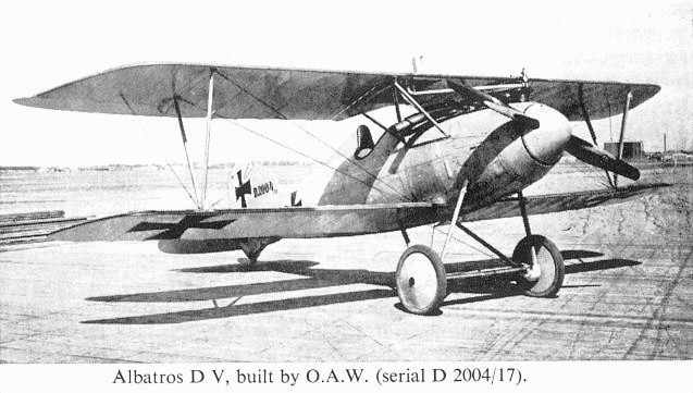
Albatros D V, built by O.A.W. (serial D 2004/17).

Albatros D Va.
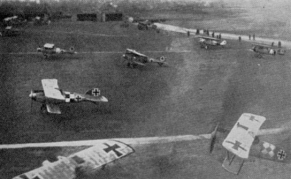
Albatros D V fighters taking off on patrol. A solitary Pfalz D III can also be seen in the background.
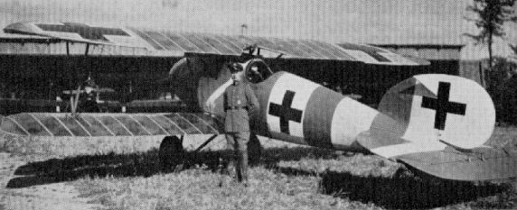
Albatros D Va of Jasta 40, flown by Lt. Dilthey.
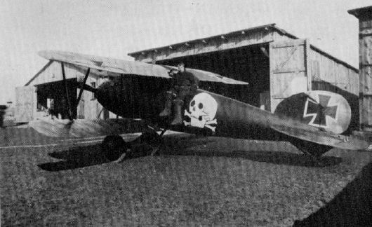
Epitomising the atmosphere of the German Jagdstaffeln, Kurt Wuslhoff poses with his skull-emblazoned Albatros D V.
Albatros D VII
Another experimental fighter from the Albatros stable was the D VII, which flew in August 1917. It was fitted with wings of parallel chord, with ailerons at all four tips linked with a strut. Conventional Albatros constructional practice was followed, but for the first time a vee-eight type engine was installed. Engine, 195 h.p. Benz Bz IIIb . Span, 9.32 m. (30 ft. 7 in.). Length, 6.615 m. (21 ft. 8 1/2 in.). Height, 2.68 m. (8 ft. 9 1/2 in.). Weights: Empty, 630 kg. (1,386 lb.). Loaded, 885 kg. (1,947 lb.). Speed, 204 km.hr. (127.5 m.p.h.). Climb, 2,000 m. (6,560 ft.) in 7 min. Duration, 2 hr. Armament, twin Spandau machine-guns.
Another experimental fighter from the Albatros stable was the D VII, which flew in August 1917. It was fitted with wings of parallel chord, with ailerons at all four tips linked with a strut. Conventional Albatros constructional practice was followed, but for the first time a vee-eight type engine was installed. Engine, 195 h.p. Benz Bz IIIb . Span, 9.32 m. (30 ft. 7 in.). Length, 6.615 m. (21 ft. 8 1/2 in.). Height, 2.68 m. (8 ft. 9 1/2 in.). Weights: Empty, 630 kg. (1,386 lb.). Loaded, 885 kg. (1,947 lb.). Speed, 204 km.hr. (127.5 m.p.h.). Climb, 2,000 m. (6,560 ft.) in 7 min. Duration, 2 hr. Armament, twin Spandau machine-guns.
Albatros Dr I
This machine, built in 1917, was virtually a D V fitted with three sets of wings to assess the triplane layout. All wings were of parallel chord with ailerons, connected by link struts, at all tips. It would seem no advantage was gained with this layout, and the type was not proceeded with. Engine, 160 h.p. Mercedes D III. Span, 8.7 m. (28 ft. 6 5/8 in.). Length, 7.3 m. (23 ft. 11 1/2 in.). Height, 2.42 m. (7 ft 11 1/4 in.). Armament, twin Spandau machine-guns.
This machine, built in 1917, was virtually a D V fitted with three sets of wings to assess the triplane layout. All wings were of parallel chord with ailerons, connected by link struts, at all tips. It would seem no advantage was gained with this layout, and the type was not proceeded with. Engine, 160 h.p. Mercedes D III. Span, 8.7 m. (28 ft. 6 5/8 in.). Length, 7.3 m. (23 ft. 11 1/2 in.). Height, 2.42 m. (7 ft 11 1/4 in.). Armament, twin Spandau machine-guns.
Albatros J I
In 1917, with the expansion of the Flieger Abt. (Infanterieftieger) Close Support units, Albatros Werke introduced the J I to supplement the A.E.G. and Junkers panzer aircraft already serving. This aircraft, like its contemporary from the A.E.G. company, was something of a hybrid, in which the complete wing cellule of the Albatros C XII was married to an ugly and cumbersome semi-armoured fuselage.
With only the 200 h.p. Benz Bz IV for a power plant (although the actual power output of this engine was closer to 225 h.p. at the low altitudes these aircraft worked), as compared with the 260 h.p. Mercedes D IV installed in the C XII, and an increase of some 350 kg. (770 lb.) in loaded weight, a drastic reduction in performance could only be expected. The reduction in climb performance did not have such serious repercussions as might be imagined, since the operational requirements for this class of machine rarely called for much altitude. When in action they could most effectively fulfil their chief offensive role, harassing the troops in the trenches, at altitudes between 50 and 500 m. (164 and 1,640 ft.).
The Albatros J I represented another trend of thought in the development of close support aircraft, coming between some earlier D.F.W.s and L.V.G.s, which had only the seats and tanks armoured, and A.E.G.s with the almost fully armoured nose.
The fuselage of the J I was basically to the well-tried Albatros formula of multi-ply formers, six main longerons (ash forward, spruce aft), with the ply skin pinned and glued to the basic structure, obviating the need for internal bracing. Unlike the A.E.G. J I, the whole of the nose was not armoured, only the actual cockpit area being covered with 5 mm. chrome nickel steel armour on the sides and underneath. To simplify manufacture the armour on the sides was largely in its original slab sheet form, cut to size, and bolted to the basic structure. To provide maximum protection for the pilot the side armour was not cut away on the front cockpit sides, but to facilitate entry and egress a panel was hinged to fold outwards and down.
Somewhat austere nose contours prevailed. The extreme nose and forward belly panels were of sheet metal, the latter with an additional bulged fairing to encase the engine sump. The panelling adjacent to the Bz IV engine was also fashioned to follow a rounded contour, but these panels also were not of armoured sheet. The remaining side nose panels, back to the armour, were of ply. The nose sloped down quite sharply from the front cockpit, thereby affording a reasonably good degree of forward vision.
Aft of the cockpit section the fuselage was ply covered, the perfectly straight slab sides being continued between the upper and lower longerons to the terminal horizontal knife-edge. The bottom surface was quite flat, but the top decking had a considerable, almost semi-circular, degree of curvature. The complete empennage was that of the C XII, with the ply-skinned tailplane and upper and lower fins and the fabric-covered, steel-tube rudder and elevator.
Although use was also made of the complete C XII wing assembly, it was mounted farther forward, with a 2° sweep on each panel to compensate for the added 490 kg. (1,078 lb.) weight of the armour and to preserve the C/G position. Installation of the radiator differed from that of the C XII, a large rectangular cooler being mounted on the centre-section leading-edge.
Due to the altered fuselage contours, it was not possible to use the original C XII undercarriage chassis, although only a slight modification to the steel-tube vee-strut lengths was necessary to employ the majority of the undercarriage components.
Operating in flights of three to six aircraft from the autumn of 1917 onwards, this class of machine was a continual thorn in the side of the Allied ground troops and artillery batteries as their downward-firing machineguns viciously probed and stabbed into trenches, gun pits and horse lines.
TECHNICAL DATA
Description: Two-seat armoured, close support.
Manufacturers: Albatros Werke G.m.b.H. (Alb.).
Power Plant: One 200 h.p. Benz Bz IV 6 cylinder in-line water-cooled engine.
Dimensions: Span, 14.14 m. (46 ft. 4 3/4 in.). Length, 8.83 m. (28 ft. 11 3/4 in.). Height, 3.37 m. (11 ft. 0 3/4 in.). Wing area, 42.82 sq.m. (462.45 sq.ft.).
Weights: Empty, 1,398 kg. (3,075 lb.). Loaded, 1,808 kg. (3,978 lb.).
Performance: Maximum speed, 140 km.hr. (87.5 m.p.h.). Initial climb, 1,000 m. (3,280 ft.) in 11.4 min.; 3,000 m. (9,840 ft.) in 50 min. Duration, 2 1/2 hr.
Armament: Two Spandau machine-guns fixed to fire downwards at 45° through floor. One free Parabellum machine-gun for observer for defence.
Albatros C XIV
Designed in 1917, the C XIV first flew in the spring of 1918. It marked a return by Albatros to a lighter, smaller type of standard two-seater from the earlier C X and C XII types; it was also the first Albatros C type to employ staggered wings. No more than one was built before it was modified into the C XV, which was scheduled for series production. Engine, 220 h.p. Benz IVa. Span, 10.4 m. (34 ft. 1 1/2 in.). Length, 6.9 m. (22 ft. 7 3/4 in.). Weights: Empty, 950 kg. (2,090 lb.). Loaded, 1,385 kg. (3,047 lb.). Duration, 3.5 hr. Armament, one Spandau and one Parabellum machine-gun.
Albatros C XV
Although it entered production, the end of the war prevented the appearance of the C XV in any quantity, as relatively few had been completed by the Armistice. Developed from the C XIV, it differed mainly in having overhung balanced ailerons and an angular cut-out in the centre-section; it was also slightly larger in overall dimensions. Standard Albatros fuselage construction was followed, with ply covering upon multi-ply formers. Engine, 220 h.p. Benz Bz IVa. Span, 11.8 m. (38 ft. 5 5/8 in.). Length, 7.47 m. (24 ft. 6 1/8 in.). Height, 3.33 m. (10 ft. 11 1/8 in.). Weights: Empty, 859 kg. (1,890 lb.). Loaded, 1,320kg.(2,904 lb.). Speed, 165km.hr. (103.12m.p.h.). Climb, 1,000 m. (3,280 ft.) in 3.4 min., 6,000 m. (19,680 ft.) in 47 min. Duration, 3 hr. Armament, one Spandau and one Parabellum machine-gun.
Albatros D IX
The D IX, which appeared early in 1918, marked the introduction of a simplified fuselage structure with slab sides and a flat bottom. Nose entry was somewhat slipshod by previous Albatros standards, and the in-line formula was revised, with no spinner. The wings were similar to those of the D VII, but additionally stayed at the intersection of the flying and landing wires, with short link struts in much the same fashion as the French Spad S VII and S XIII. Only one example was built. Engine, 180 h.p. Mercedes D IIIa. Span, 10.4 m. (34 ft. 1 1/2 in.). Length, 6.65 m. (21 ft. 9 7/8 in.). Height, 2.75 m. (9 ft. 0 3/8 in.). Weights: Empty, 677 kg. (1,489 lb.). Loaded, 897 kg. (1,973 lb.). Speed, 155 km.hr. (96.875 m.p.h.). Climb, 1,000 m. (3,280 ft.) in 4 min., 5,000 m. (16,400 ft.) in 35 min. Duration, 1.5 hr. Armament, twin Spandau machine-guns.
Albatros D X
Another of the early 1918 prototypes from Albatros was the D X. The slab-sided fuselage of the D IX was retained, but a neatly spinnered vee-eight Benz IIIb of 195 h.p. was installed. Simplified wing bracing utilizing I struts was introduced, and the centre-section bracing was reinforced by a strut running right down to the lower wing root. This aircraft, serialled 2206/18, took part in the second D types Competition at Adlershof in June 1918. At a loaded weight of 888 kg. (1,954 lb.), it attained 5,000 m. (16,400 ft.) in 22 min., but on another occasion took 35.6 min. to reach the same height, taking 17 min to climb the last 1,000 m. Span, 9.84 m. (32 ft. 3 3/8 in.). Length, 618 m. (20 ft. 3 1/4 in.). Height, 2.75 m. (9 ft. 0 3/8 in.). Weights: Empty, 666 kg. (1,465 lb.). Loaded, 905 kg. (1,991 lb.). Speed, 170 km.hr. (106.25 m.p.h.). Duration, 1.5 hr. Armament, twin Spandau machine-guns.
Albatros D XI
The D XI was the first of the Albatros D type lineage to use a rotary engine, and was fitted with the powerful geared Siemens-Halske Sh III of 160 h.p. This engine was installed in a horse-shoe cowling with pointed "elephant-ear" extensions to the rear. These acted as venturi and assisted cooling by sucking air through the cowling, which action also reduced drag.
Two prototypes were built, the first with a four-blade airscrew and balanced ailerons of parallel chord, and the second machine with unbalanced ailerons of inverse taper and a two-blade propeller. Hollow wooden I struts braced the wings. Flying and landing loads were taken by two hollow diagonal struts, which dispensed with need for wire bracing. Both aircraft featured plywood box-type fuselage with built-in fin, the remainder of the aircraft being fabric covered.
Initially flown in February 1918, the D XIs participated in the second D type competition. Remarkable climb performances were established, but no production order was given. Span, 8.0 m. (26 ft. 3 in.). Length, 5.58 m. (18 ft. 3 3/4 in.). Height, 2.86 m. (9 ft. 4 5/8 in.). Area, 18.5 sq.m. (199.8 sq.ft.). Weights: Empty, 494 kg. (1,087 lb.). Loaded, 689 kg. (1,516 lb). Speed, 190 km.hr. (118.75 m.p.h.). Climb (D Comp. at loaded weight of 723 kg.), 15,000 m. (16,400 ft.) in 151 min. Duration, 1.5 hr. Armament, twin Spandau machine-guns.
Albatros D XII (with Bohme undercarriage)
At least two D XII prototypes were built. D 2210/18 was first flown in March 1918 and participated in the second D types Competition. A modified machine fitted with a Bohme undercarriage which featured compressed-air shock absorbers flew in April 1918. This undercarriage necessitated an additional strut, which may just be observed running vertically above the wheel in the above photograph. The D XIIs again featured the slab-sided ply-covered fuselage introduced with the D X. There was again a variation in the ailerons, the Bohme undercarriage machine having unbalanced ailerons of inverse taper, and D 2211/18 having overhung balanced ailerons of parallel chord. Engine, 160 h.p. Mercedes D III. Span, 8.2 m. (26 ft. 10 7/8 in.). Length, 5.785 m. (18 ft. 11 3/4 in.). Height, 2.8 m. (9 ft. 2 1/4 in.). Area, 19.84 sq.m. (214 sq.ft.). Weights: Empty, 580 kg. (1.276 lb.). Loaded, 760 kg. (1,672 lb.). Speed, 180 km.hr. (112.5 m.p.h.). Climb, 8,000 m. (26,240 ft.) in 54 min. Duration, 1 hr. Armament, twin Spandau machineguns.
The second D XII (2211/18) was fitted with B.M.W. IIIa engine of some 185 h.p. and participated in the third D types Competition in October 1918.
Albatros Dr II
Built in 1918, the Dr II consisted mainly of D X components with a triplane set of wings. These were of parallel chord, heavily staggered and braced with very wide I struts reminiscent of the Sopwith triplane. Ailerons were fitted to all wingtips. Frontal-type radiators were mounted in the centre-section between the upper and centre wings, and undoubtedly caused considerable drag. Engine, 195 h.p. Benz lVb vee-eight. Span, 10.0 m. (32 ft. 9 3/4 in.). Length, 6.18 m. (20 ft. 3 1/4 in.). Height, 3.34 m. (10 ft. 11 1/2 in.). Area, 26.6 sq.m. (287.28 sq.ft.). Weights: Empty, 676 kg. (1,487 lb.). Loaded, 915 kg. (2,013 lb.).
Built in 1918, the Dr II consisted mainly of D X components with a triplane set of wings. These were of parallel chord, heavily staggered and braced with very wide I struts reminiscent of the Sopwith triplane. Ailerons were fitted to all wingtips. Frontal-type radiators were mounted in the centre-section between the upper and centre wings, and undoubtedly caused considerable drag. Engine, 195 h.p. Benz lVb vee-eight. Span, 10.0 m. (32 ft. 9 3/4 in.). Length, 6.18 m. (20 ft. 3 1/4 in.). Height, 3.34 m. (10 ft. 11 1/2 in.). Area, 26.6 sq.m. (287.28 sq.ft.). Weights: Empty, 676 kg. (1,487 lb.). Loaded, 915 kg. (2,013 lb.).
Albatros J II
This aircraft was an improvement on the J I, with the armour extended forward to enclose the engine. At least four examples were built, numbered 126/18, 133/18, 167/18 and 169/18, but in view of the success of the Junkers J I, it is doubtful if many more existed. The downward twin machine-guns may be seen in the photograph protruding through the floor between the undercarriage legs. This arrangement was subsequently abandoned due to difficult and inaccurate sighting at low altitude. Engine, 220 h.p. Benz IVa. Span, 13.55 m. (44 ft. 5 1/2 in.). Length, 8.433 m. (27 ft. 8 in.). Height, 3.4 m. (11 ft. 1 7/8 in.). Area, 43.2 sq.m. (466.56 sq.ft.). Weights: Empty, 1,027 kg. (2,259 lb.). Loaded, 1,927 kg. (4,239 lb.). Speed, 140 km.hr. (87.5 m.p.h.). Climb, 1,000 m. (3,280 ft.) in 8.7 min. Duration, 2.5 hr. Armament, two fixed Spandau machine-guns, one manually operated Parabellum machinegun in rear cockpit.
This aircraft was an improvement on the J I, with the armour extended forward to enclose the engine. At least four examples were built, numbered 126/18, 133/18, 167/18 and 169/18, but in view of the success of the Junkers J I, it is doubtful if many more existed. The downward twin machine-guns may be seen in the photograph protruding through the floor between the undercarriage legs. This arrangement was subsequently abandoned due to difficult and inaccurate sighting at low altitude. Engine, 220 h.p. Benz IVa. Span, 13.55 m. (44 ft. 5 1/2 in.). Length, 8.433 m. (27 ft. 8 in.). Height, 3.4 m. (11 ft. 1 7/8 in.). Area, 43.2 sq.m. (466.56 sq.ft.). Weights: Empty, 1,027 kg. (2,259 lb.). Loaded, 1,927 kg. (4,239 lb.). Speed, 140 km.hr. (87.5 m.p.h.). Climb, 1,000 m. (3,280 ft.) in 8.7 min. Duration, 2.5 hr. Armament, two fixed Spandau machine-guns, one manually operated Parabellum machinegun in rear cockpit.
Albatros W 8
Marine Nos. 5001-5003 were allocated to W 8 type, but only the first two aircraft are believed to have been supplied, during 1918. Intended for fighting patrol duties and as a possible successor to the Brandenburg W 12, the W 8 incorporated some of the features of the Heinkel-designed machine, notably the high-set tailplane. However, as this was now set atop the vertical fin, it was particularly vulnerable and had not the strength factor of the Brandenburg, with its upswept fuselage to carry the tailplane. The other Albatros W 8 differed only in being fitted with a pointed spinner. Engine, 195 h.p. Benz IIIb vee eight. Span, 11.46 m. (37 ft. 1 1/4 in.). Length, 9.59 m. (31 ft. 5 5/8 in.). Height, 3.39 m. (11 ft. 1 1/2 in.). Speed, 150 km.hr. (93.75 m.p.h.). Climb, 1,000 m. (3,280 ft.) in 6.5 min., 3,000 m. (9,840 ft.) in 34 min. Useful load, 500 kg. (1,100 lb.). Duration, 3.5 hr. Armament, one fixed Spandau machine-gun forward, one manually operated Parabellum machine-gun in rear cockpit.
Marine Nos. 5001-5003 were allocated to W 8 type, but only the first two aircraft are believed to have been supplied, during 1918. Intended for fighting patrol duties and as a possible successor to the Brandenburg W 12, the W 8 incorporated some of the features of the Heinkel-designed machine, notably the high-set tailplane. However, as this was now set atop the vertical fin, it was particularly vulnerable and had not the strength factor of the Brandenburg, with its upswept fuselage to carry the tailplane. The other Albatros W 8 differed only in being fitted with a pointed spinner. Engine, 195 h.p. Benz IIIb vee eight. Span, 11.46 m. (37 ft. 1 1/4 in.). Length, 9.59 m. (31 ft. 5 5/8 in.). Height, 3.39 m. (11 ft. 1 1/2 in.). Speed, 150 km.hr. (93.75 m.p.h.). Climb, 1,000 m. (3,280 ft.) in 6.5 min., 3,000 m. (9,840 ft.) in 34 min. Useful load, 500 kg. (1,100 lb.). Duration, 3.5 hr. Armament, one fixed Spandau machine-gun forward, one manually operated Parabellum machine-gun in rear cockpit.
Albatros (O.A.W.) C I
Two C type machines produced by the Albatros Schneidemuhl factory. The C I, of which two are thought to have been built during 1915, was powered with 150 h.p. Benz. The C II, built in 1916, was fitted with the geared straight eight Mercedes D IV.
Two C type machines produced by the Albatros Schneidemuhl factory. The C I, of which two are thought to have been built during 1915, was powered with 150 h.p. Benz. The C II, built in 1916, was fitted with the geared straight eight Mercedes D IV.
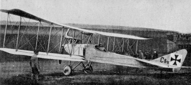
Albatros (O.A.W.) C I
Alter Type A I
Single seat "Nieuport type" machine produced by Ludwig Alter Werke, Darmstadt. Engine, probably Oberursel U II 120 h.p.
Single seat "Nieuport type" machine produced by Ludwig Alter Werke, Darmstadt. Engine, probably Oberursel U II 120 h.p.
Aviatik B I
The Aviatik B I appeared in 1914 in both two- and three-bay versions. Both types are seen in the illustration. Power unit was 100 h.p. Mercedes D I.
Aviatik B II
Constructed and used during 1915, the B II appeared in small numbers and was a neat-looking aeroplane for the period. The painting of the patee crosses underneath the upper wingtips and on the wheel discs is noteworthy. As in the majority of B types, the pilot sat in the rear cockpit and the observer forward. Engine, 120 h.p. Mercedes D II. Span, 12.49 m. (40 ft. 11 3/4 in.). Length, 7.10 m. (23 ft. 3 5/8 in.).
A varied collection of two-seaters at a German airfield in 1915. The aircraft are Albatros B IIs , Aviatik B Is and B IIs.
Aviatik C I and C III
One of the first products of the German aircraft industry to become well known to the public during the First World War was that of the Automobil und Aviatik A G . After the Taube had been well publicised by the daily Press, the next name brought to popular notice was that of Aviatik. It is open to doubt whether all aircraft referred to by the Press as Aviatiks were indeed such. The firm was well known in aviation circles before the war, and after hostilities opened many of its B I and B II types were in service on unarmed reconnaissance duties.
The first Aviatik type to see large-scale production was the C I, which came out in early 1915, powered with the 160 h.p. Mercedes D III engine and armed with a defensive machine-gun for the observer. The Aviatik was unique among German operational tractor C class two-seaters in having the pilot sitting in the rear cockpit and the observer forward, with his machine-gun clipped on a sliding mounting fitted on a rail at either side of the cockpit. The gun was transferred from one side of the cockpit to the other, as occasion demanded, and was secured with a quick-release mechanism. This seating arrangement was the same as that used by the British in their B.E. 2c (and its variants), and suffered the same shortcomings, i.e. restricted field of fire when it was necessary to use the machinegun, and an equally restricted view when making reconnaissance observations. Later, an effort was made to rectify this by reversing the seating arrangements, but by that time superior designs were coming from the Albatros, L.V.G. and Rumpler factories.
There was nothing spectacular or unique about the construction of the C I. The fuselage was a conventional box-girder structure of four spruce and with a rounded top decking of light stringers, tapered to a vertical knife-edge aft. Forward, the longerons converged and terminated in a sheet steel end plate, fretted with lightening holes. This, and the first two formers, supported the ash engine bearers, which were additionally braced with steel tubes.
Curved aluminium panels surrounded the 160 h.p. Mercedes D III engine at the nose and the forward top decking, leaving the cylinder block exposed. The sides and underneath of the nose, as far aft as the leading-edge of the lower wings, were covered with flat aluminium sheet, the remainder of the fuselage being fabric-covered. On the first C Is the radiators were located on the fuselage sides, but an improved Teeves and Braun radiator was soon substituted and mounted on the front centre-section struts, just below the leading edge of the top wing. Forward view was also materially obstructed by the chimney-type manifold exhausting up and over the top wing.
The rectangular-shaped fabric-covered wings were of all-wood construction except for the steel-tube compression struts. The main spars were made in two halves (of spruce), spindled out to form a U-section and then joined together with hardwood tongues to form hollow box-spars. The ribs themselves were of poplar or lime (linden), and the trailing edge of wire, with the characteristic scalloped outline. Plain, unbalanced, parallel-chord ailerons were hinged direct to the rear spar at the upper wingtips. The centre-section cabane, of inverted trestle type, and all interplane struts were of streamlined steel tube and braced with stranded cables. The bracing of the inboard bay was unusual, in that the front flying wire was anchored to the rear spar junction with the fuselage and the rear flying wire was anchored to the front spar junction. The landing wires ran from the lower end of the inner struts and were terminally anchored to the lop longeron instead of running to the apex of the centre-section trestle, as was usual. This arrangement was doubtless to facilitate operation of the defensive gun on the tubular rails on the sides of the front cockpit.
A normal vee-type undercarriage was fitted, the actual struts being joined by a short horizontal tube at the apex which served as an anchorage for the rubber cord shock absorbers. An elliptical tube spreader-bar joined the vees in front of the axle and a wire strainer connected them behind the axle. Stranded cables cross braced the undercarriage between the front legs.
With the exception of the tailplane ribs, which were of wood, the whole of the tail surfaces were of light-gauge steel tube; the tailplane, combined with the split elevators, being of distinctive kidney shape. The comma-shaped rudder was the only control surface to be balanced, and was hinged to a long narrow triangular I'm which was braced to the tailplane with a light steel strut. Underneath, the tailplane was braced to the fuselage with two light struts on each side.
<...>
Aviatiks were used by the Fl. Abt. units for reconnaissance, and on occasion they were operated in nights of anything from three t o six aircraft, solely as armed escort t o unarmed reconnaissance machines. The destruction of an Aviatik on 7th November 1915 was instrumental in the award of the Victoria Cross t o 2nd Lt. G. S. M. Insall of No. 11 Sqdn. R . F . C , who, flying a Vickers Gunbus, forced down the Aviatik. Its destruction was completed by his dropping a bomb on it.
TECHNICAL DATA
Description: Two-seat reconnaissance and escort.
Manufacturers:
Automobil und Aviatik A.G. (Av.).
Hannoversche Waggonfabrik A.G. (Han.).
Power Plant: One 160 h.p. Mercedes D III 6 cylinder in-line water-cooled engine.
Dimensions: Span, 12 5 m. (41 ft. 0 1/4 in.), C I; 118 m. (38 ft. 5 5/8 in.), C III. Length, 7.925 m. (26 ft. 0 in.), C I; 8.08 m. (26 ft. 6 1/8 in.), C III. Height, 2.95 m. (9 ft. 8 1/8 in.), C I; 2.95 m. (9 ft. 8 1/8 in.), C III. Wing area, 43 sq.m. (465.4 sq.ft.), C I; 35 sq.m. (378 sq.ft.), C III.
Weights: Empty, 750 kg. (1,650 lb.), C I; 980 kg. (2,156 lb.), C III. Loaded, 1,242 kg. (2,732 lb.), C I; 1,340 kg. (2,948 lb.), C III.
Performance: Maximum speed, 142 km.hr. (88.75 m.p.h.), C I; 160 km.hr. (100 m.p.h.), C III. Initial climb, 1,000 m. (3,280 ft.) in 12 min., C I; 1,000 m. (3,280 ft.) in 7 min., C III. Ceiling, 3,500 m. (11,480 ft.), C I; 4,500 m. (14,760 ft.) in 55 min., C III. Duration 3 hr.
Armament: One Parabellum machine-gun for observer mounted on rails on either side of front cockpit, the gun transferred as necessary. Later, on the C III, two guns were mounted, one on either rail.
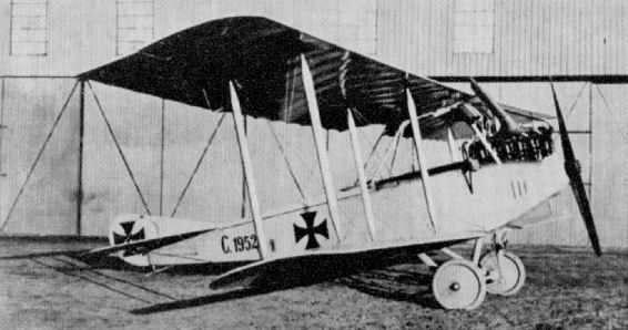
Aviatik C I (serial C 1952/15).
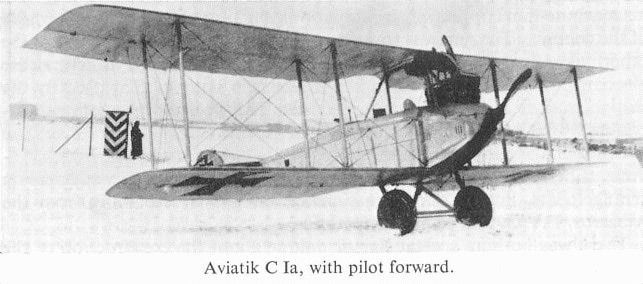
Aviatik C Ia, with pilot forward.
Aviatik C II
Used briefly between Aviatik types C I and C III, the C II was generally similar, although the tail surfaces were noticeably different in having no vertical fin surface. The fuselage appearance was enhanced by the inclusion of a headrest aft of the rear cockpit. The observer still occupied the front cockpit, operating his Parabellum machinegun from rails along the cockpit sides. 43 aircraft of this type were ordered and delivered. Serial Nos. identified: 3108/16, 3135/16 and 3142/16. Engine, 200 h.p. Benz Bz IV. Span 11.71 m. (37 ft. 7 in.). Weight loaded 1,509 kg. (3,320 lb.).
Used briefly between Aviatik types C I and C III, the C II was generally similar, although the tail surfaces were noticeably different in having no vertical fin surface. The fuselage appearance was enhanced by the inclusion of a headrest aft of the rear cockpit. The observer still occupied the front cockpit, operating his Parabellum machinegun from rails along the cockpit sides. 43 aircraft of this type were ordered and delivered. Serial Nos. identified: 3108/16, 3135/16 and 3142/16. Engine, 200 h.p. Benz Bz IV. Span 11.71 m. (37 ft. 7 in.). Weight loaded 1,509 kg. (3,320 lb.).
Aviatik C I and C III
<...>
During 1916. in an endeavour to meet the demand for better performance, the Aviatik C III was introduced. This machine, however, was little more than a refined C I. The nose contours were considerably cleaned up and a large spinner fixed to the propeller; a new exhaust manifold ejecting horizontally to starboard was also fitted. A further improvement was the installation of the new aerofoil-shape radiator in the starboard side of the top-wing centre-section. In addition to improving forward vision considerably, these refinements added some 18 km.hr. (11.25 m.p.h.) to the speed. Wingspan was reduced, as was the chord of the ailerons, which were hinged to a false spar. There was also improvement in the fuel system, which in the C I had consisted of no fewer than four separate tanks, with a complicated system of cocks and piping to enable the engine to run on any separate tank. Apart from these modifications, the airframe remained virtually that of the earlier aircraft.
Aviatiks were used by the Fl. Abt. units for reconnaissance, and on occasion they were operated in nights of anything from three t o six aircraft, solely as armed escort t o unarmed reconnaissance machines. The destruction of an Aviatik on 7th November 1915 was instrumental in the award of the Victoria Cross t o 2nd Lt. G. S. M. Insall of No. 11 Sqdn. R . F . C , who, flying a Vickers Gunbus, forced down the Aviatik. Its destruction was completed by his dropping a bomb on it.
TECHNICAL DATA
Description: Two-seat reconnaissance and escort.
Manufacturers:
Automobil und Aviatik A.G. (Av.).
Hannoversche Waggonfabrik A.G. (Han.).
Power Plant: One 160 h.p. Mercedes D III 6 cylinder in-line water-cooled engine.
Dimensions: Span, 12 5 m. (41 ft. 0 1/4 in.), C I; 118 m. (38 ft. 5 5/8 in.), C III. Length, 7.925 m. (26 ft. 0 in.), C I; 8.08 m. (26 ft. 6 1/8 in.), C III. Height, 2.95 m. (9 ft. 8 1/8 in.), C I; 2.95 m. (9 ft. 8 1/8 in.), C III. Wing area, 43 sq.m. (465.4 sq.ft.), C I; 35 sq.m. (378 sq.ft.), C III.
Weights: Empty, 750 kg. (1,650 lb.), C I; 980 kg. (2,156 lb.), C III. Loaded, 1,242 kg. (2,732 lb.), C I; 1,340 kg. (2,948 lb.), C III.
Performance: Maximum speed, 142 km.hr. (88.75 m.p.h.), C I; 160 km.hr. (100 m.p.h.), C III. Initial climb, 1,000 m. (3,280 ft.) in 12 min., C I; 1,000 m. (3,280 ft.) in 7 min., C III. Ceiling, 3,500 m. (11,480 ft.), C I; 4,500 m. (14,760 ft.) in 55 min., C III. Duration 3 hr.
Armament: One Parabellum machine-gun for observer mounted on rails on either side of front cockpit, the gun transferred as necessary. Later, on the C III, two guns were mounted, one on either rail.
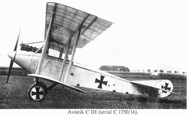
Aviatik C.Ia 1750/16 was the aerodynamic test-bed and prototype for the Aviatik C.III powered by the same 160 hp Mercedes D.III engine as the C.I. The C.Ia gained a useful speed increase from its additional streamlining. The later Aviatik C.II also benefited from these aerodynamic improvements although it used a different engine and airframe.
Aviatik D II
The D II was Aviatik's first original design D type. Appearing late in 1916, the D II featured the plywood-skinned fuselage favoured by Albatros. However, the internal structure differed, as the whole of the forward fuselage framework was of steel tube. Engine fitted was 160 h.p. Mercedes D III. Only a single aircraft was built.
The D II was Aviatik's first original design D type. Appearing late in 1916, the D II featured the plywood-skinned fuselage favoured by Albatros. However, the internal structure differed, as the whole of the forward fuselage framework was of steel tube. Engine fitted was 160 h.p. Mercedes D III. Only a single aircraft was built.
Aviatik C V
This gull-winged prototype, which appeared in 1917, remained no more than an experiment. Undoubtedly the upward field of view for both crew members was excellent. The novel system of interplane bracing is notable. The 180 h.p. Argus As III motor was neatly cowled, and it appears from the illustration that the intention was to fit the airscrew with a spinner. Armament, one Spandau and one Parabellum machine-gun.
This gull-winged prototype, which appeared in 1917, remained no more than an experiment. Undoubtedly the upward field of view for both crew members was excellent. The novel system of interplane bracing is notable. The 180 h.p. Argus As III motor was neatly cowled, and it appears from the illustration that the intention was to fit the airscrew with a spinner. Armament, one Spandau and one Parabellum machine-gun.
Aviatik C VIII
There being no record of an Aviatik C VII, the C VIII is presumed the next in sequence. Constructed in 1917, it was reminiscent of the Halberstadt CL II, and may have been intended eventually as a light two-seater. The ply-skinned fuselage featured a small under-keel to afford a greater gap than would otherwise have been possible. Additional struts secured the lower wing panels to this keel. Power unit was 160 h.p. Mercedes D III.
There being no record of an Aviatik C VII, the C VIII is presumed the next in sequence. Constructed in 1917, it was reminiscent of the Halberstadt CL II, and may have been intended eventually as a light two-seater. The ply-skinned fuselage featured a small under-keel to afford a greater gap than would otherwise have been possible. Additional struts secured the lower wing panels to this keel. Power unit was 160 h.p. Mercedes D III.
Aviatik D III
Emerging from the Aviatik workshops in late 1917, the D III was another experimental type, and two prototypes were built. Both aircraft took part in the second D types Competition at Adlershof in 1918. During two test climbs to 5,000 m. (16,400 ft.) times of 20.5 min. and 22.5 min. were recorded. In order to obtain an increase in gap, the lower wings were mounted on a small keel extended from the fuselage. As in the D II, the fuselage was plywood covered, the cylinder-heads of the ungeared 195 h.p. Benz IIIb vee-eight motor being left well exposed. Span was 9.0 m. (29 ft. 6 3/8 in.) upper and 8.04 m. (26 ft. 4 5/8 in.) lower, with an area of 21 sq.m. (226.8 sq.ft.). The gross weight was 864 kg. (1,901 lb.).
Emerging from the Aviatik workshops in late 1917, the D III was another experimental type, and two prototypes were built. Both aircraft took part in the second D types Competition at Adlershof in 1918. During two test climbs to 5,000 m. (16,400 ft.) times of 20.5 min. and 22.5 min. were recorded. In order to obtain an increase in gap, the lower wings were mounted on a small keel extended from the fuselage. As in the D II, the fuselage was plywood covered, the cylinder-heads of the ungeared 195 h.p. Benz IIIb vee-eight motor being left well exposed. Span was 9.0 m. (29 ft. 6 3/8 in.) upper and 8.04 m. (26 ft. 4 5/8 in.) lower, with an area of 21 sq.m. (226.8 sq.ft.). The gross weight was 864 kg. (1,901 lb.).
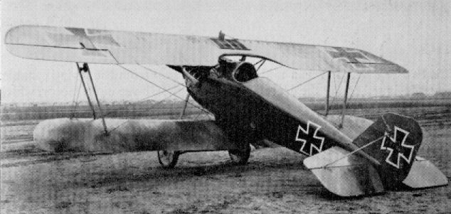
Aviatik C IX
Three prototypes were constructed during 1918 (6306/18-6308/18) and differed mainly in the shape of the tail surfaces. One aircraft had ailerons on the top wing only; the other had ailerons at all four wingtips. Airframe 6307/18 was tested to destruction at Adlershof over the period 13th to 18th June 1918. Engine, 200 h.p. Benz IV. Weights: Empty, 980 kg. (2.156 lb.). Loaded, 1,340 kg. (2,948 lb.). Speed, 160 km.hr. (100 m.p.h.). Ceiling, 4,500 m. (14.760 ft.). Armament, one Spandau and one Parabellum machine-gun.
Three prototypes were constructed during 1918 (6306/18-6308/18) and differed mainly in the shape of the tail surfaces. One aircraft had ailerons on the top wing only; the other had ailerons at all four wingtips. Airframe 6307/18 was tested to destruction at Adlershof over the period 13th to 18th June 1918. Engine, 200 h.p. Benz IV. Weights: Empty, 980 kg. (2.156 lb.). Loaded, 1,340 kg. (2,948 lb.). Speed, 160 km.hr. (100 m.p.h.). Ceiling, 4,500 m. (14.760 ft.). Armament, one Spandau and one Parabellum machine-gun.
Aviatik D IV
Very little information is available on the Aviatik D IV single-seat fighter, but this extremely rare photograph has survived, showing the fuselage without the mainplanes and vee-type engine.
Aviatik D VII
Stemming from the earlier D VI, the D VII did not differ radically apart from a drastic revision of the tail surfaces. Engine, 195 h.p. Benz IIIb geared. Span, 9.66 m. (31 ft. 8 3/8 in.). Length, 6.1 m. (20 ft. 0 1/4 in.). Height, 2.5 m. (8 ft. 2 1/2 in.). Weights: Empty, 745 kg. (1,639 lb.). Loaded, 945 kg. (2,079 lb.). Speed, 192 km.hr. (120 m.p.h.). Climb, 6,000 m. (19,680 ft.) in 24 min. Duration, ca. 1 hr. Armament, twin Spandau machine-guns.
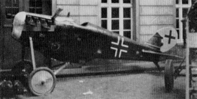
Aviatik D IV ???
Aviatik D VI
This two-bay fighter was a mid-1918 production from the Aviatik stable. It was designed round the geared 195 h.p. Benz IIIb vee-eight motor, which was installed with a large square car-type radiator on the nose. Normal wooden construction was used, with ply-covered fuselage and fabric-covered flying surfaces. Only one D VI was built, and it was soon succeeded by the D VII, but it took part in the second D types Competition and recorded a climb to 5,000 m. (16,400 ft.) in 20.3 min. and 17.1 min. on two different attempts. The loaded weight for the climbs was 920 kg. (2,024 lb.). Armament, twin Spandau machine-guns.
This two-bay fighter was a mid-1918 production from the Aviatik stable. It was designed round the geared 195 h.p. Benz IIIb vee-eight motor, which was installed with a large square car-type radiator on the nose. Normal wooden construction was used, with ply-covered fuselage and fabric-covered flying surfaces. Only one D VI was built, and it was soon succeeded by the D VII, but it took part in the second D types Competition and recorded a climb to 5,000 m. (16,400 ft.) in 20.3 min. and 17.1 min. on two different attempts. The loaded weight for the climbs was 920 kg. (2,024 lb.). Armament, twin Spandau machine-guns.
B.F.W. CL I
Designed to CL specification as an improvement on the Halberstadt CL II, but remained only a prototype. Engine, 160 h.p. Mercedes D III.
B.F.W. CL II
Development of B.F.W. CL I. Prototype only. Engine, 175 h.p. MAN III. Test flown July 1918.
B.F.W. CL III
Final aircraft in B.F.W. CL series. Remained prototype only. Engine, 200 h.p. Benz Bz IV.
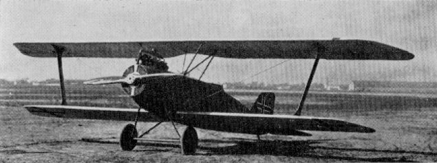
B.F.W. CL III
A Germania Single-Strut Biplane of the "C" Class, with a curious circular-shaped radiator.
A Germania Single-Strut Biplane of the "C" Class, with a curious circular-shaped radiator.
B.F.W. Monoplane
An experimental monoplane of 1918 with forward sweep on wings and which obviously utilised a CL II/III fuselage. Engine, 180 h.p. Argus As III.
An experimental monoplane of 1918 with forward sweep on wings and which obviously utilised a CL II/III fuselage. Engine, 180 h.p. Argus As III.
B.F.W. N I
An experimental two-seat triplane night bomber, of which only one was built to carry 744 kg. (1,636 lb.) of bombs! Engine, 260 h.p. Mercedes DIVa. Weights: Empty. 1,500kg.(3,300 lb.). Loaded,2,500kg.(5,500 lb.). Armament, one Parabellum machine-gun. No photograph available.
An experimental two-seat triplane night bomber, of which only one was built to carry 744 kg. (1,636 lb.) of bombs! Engine, 260 h.p. Mercedes DIVa. Weights: Empty. 1,500kg.(3,300 lb.). Loaded,2,500kg.(5,500 lb.). Armament, one Parabellum machine-gun. No photograph available.
Caspar D I
Designed by Ernst Heinkel, this twin-engined, single-seat lighter was built by Hanseatische Flugzeug-Werke in late 1918, but it was destroyed in 1919 when a motor broke loose during a ground test. Engines, two 100 h.p. Oberursel U I rotaries.
Designed by Ernst Heinkel, this twin-engined, single-seat lighter was built by Hanseatische Flugzeug-Werke in late 1918, but it was destroyed in 1919 when a motor broke loose during a ground test. Engines, two 100 h.p. Oberursel U I rotaries.
Daimler L 6 and D I
Previously having built other manufacturers' products under licence (FF G III, G IV, etc.), the L 6 was the Daimler Motorengesellschaft Werke's first excursion into the single-seater design field. This extremely neat fighter was designed round Daimler's own 185 h.p. D IIIb vee-eight engine. Six aircraft of the type were built, and one participated in the second D types Competition at Adlershof during the May-June 1918 period. Three test climbs to 5,000 m. (16,400 ft.) were made at a loaded weight of 922 kg. (2,028 lb.), and recorded times of 19.4 min., 21.4 min. and 16.8 min. All tests were made with the same airscrew, a "Propulsor" of 3.1 m. diameter and 2.85 m. pitch, which illustrates how performance varied, even with one aircraft. Armament, twin Spandau machine-guns.
Daimler L 9
Single-seat fighter developed from D I. Revised tail surfaces and interplane bracing struts. Prototype only built. Large lifting surface fairing over the axle as on Fokker types. Engine, 185 h.p. Daimler D IIIb.
Daimler L 11
Built to the parasol formula, the L 11 was remarkable in having ailerons that were balanced by independent surfaces which overhung the tips, but at the leading edge, thereby imparting a back-to-front appearance to the wing. Actually these overhung surfaces were more accurately servos. Engine, 185 h.p. Daimler D IIIb.
Daimler L 14
Although designed towards the end of the war, the L 14 was not completed until after the Armistice. It is reputed to have attained 190 km.hr. (118.75 m.p.h.) on test, and climbed 5,000 m. (16,400 ft.) in 25 min. with the 185 h.p. Daimler D IIIb engine installed.

A Mercedes-Daimler Single-seater "Wireless" Parasol Monoplane. Type L 11, with curiously-shaped wing-tips. 185 h.p. Daimler IIIb engine.
Daimler L 8
A two-seat fighter which appeared in 1918. Plywood fuselage. Prototype only constructed. Engine, 185 h.p. Daimler IIIb. Armament, one Spandau and one Parabellum machine-gun.
A two-seat fighter which appeared in 1918. Plywood fuselage. Prototype only constructed. Engine, 185 h.p. Daimler IIIb. Armament, one Spandau and one Parabellum machine-gun.
D.F.W. B I
Illustrated is D.F.W. Type MD 14 B I, a 1914 reconnaissance and school machine. Originally it had a welded steel tube fuselage, but later versions (illustrated) had an all-wood, ply-covered structure. Here the machine has been fitted with machine-gun, and when later fitted with the more powerful Benz III motor was re-designated C. Engine, 100 h.p. Mercedes D I. Span, 14.0 m. (45 ft. 11 1/4 in.). Length, 8.4m. (27 ft. 6 3/4 in.). Weights: Empty, 650 kg. (1,430 lb.). Loaded, 1,015 kg. (2,233 lb.). Speed, 120 km.hr. (75 m.p.h.).
Illustrated is D.F.W. Type MD 14 B I, a 1914 reconnaissance and school machine. Originally it had a welded steel tube fuselage, but later versions (illustrated) had an all-wood, ply-covered structure. Here the machine has been fitted with machine-gun, and when later fitted with the more powerful Benz III motor was re-designated C. Engine, 100 h.p. Mercedes D I. Span, 14.0 m. (45 ft. 11 1/4 in.). Length, 8.4m. (27 ft. 6 3/4 in.). Weights: Empty, 650 kg. (1,430 lb.). Loaded, 1,015 kg. (2,233 lb.). Speed, 120 km.hr. (75 m.p.h.).
D.F.W. B II
Produced during 1915 as a school machine. Kurt Wusthoff, who later became a well-known fighter pilot, trained on this type at the Leipzig-Lindenthal school. Engine, 100 or 120 h.p. Mercedes D I or D II. Span, 12.60 m. (41 ft. 4 1/8 in.). Weights: Empty, 747 kg. (1,644 lb.). Loaded, 1,190 kg. (2,618 lb.).
D.F.W. C I and C II
Produced in 1916 as a general duties machine, the C I and C II were conventional two-seaters and differed only in that in the C I the pilot sat in the aft position; in the C II the crew positions were reversed. Engine, 150 h.p. Benz III. Span, 11.2 m. (36 ft. 9 in.). Length, 7.2 m. (23 ft. 7 1/2 in.). Area, 33 sq.m. (356.4 sq.ft.). Weights: Empty, 725 kg. (1,595 lb.). Loaded, 1,235 kg. (2,717 lb.). Speed, 140 km.hr. (87.5 m.p.h.). Ceiling, 4,000 m. (13,120 ft.). Armament, one Parabellum machine-gun in rear cockpit.
D.F.W. C Type
Experimental C type, September 1916. A fair degree of similarity in profile to the later C IV is apparent. The single-bay "I" struts were unusual for a two-seater. Engine, 150 h.p. Benz Bz III.
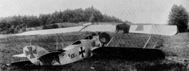
D.F.W. B II
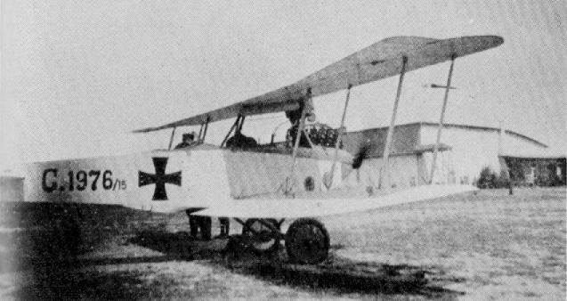
D.F.W. C I
D.F.W. Pusher Biplane
No details available on this pusher (Gitterschwanz) two-seater, although the wing cellule would appear to be similar to that of the C V. Possibly, but not certainly, designated C III. Engine, 150 h.p. Benz Bz III.
No details available on this pusher (Gitterschwanz) two-seater, although the wing cellule would appear to be similar to that of the C V. Possibly, but not certainly, designated C III. Engine, 150 h.p. Benz Bz III.
D.F.W. Floh (Flea)
A 1915 prototype of ungainly proportions. Visibility from cockpit was very poor, and the aircraft crashed on test. Engine, 100 h.p. Mercedes D I. Span, 6.2 m. (20 ft. 4 1/8 in.). Length, 4.5 m. (14 ft. 9 1/4 in.). Area, 15 sq.m. (162 sq.ft.). Weights: Empty, 420 kg. (924 lb.). Loaded, 650kg. (1,430 lb.).
A 1915 prototype of ungainly proportions. Visibility from cockpit was very poor, and the aircraft crashed on test. Engine, 100 h.p. Mercedes D I. Span, 6.2 m. (20 ft. 4 1/8 in.). Length, 4.5 m. (14 ft. 9 1/4 in.). Area, 15 sq.m. (162 sq.ft.). Weights: Empty, 420 kg. (924 lb.). Loaded, 650kg. (1,430 lb.).
D.F.W. C IV
Built during 1916, the C IV featured single-bay wings with radiator mounted under the upper leading-edge. Engine, 150 h.p. Benz Bz. III. Armament, one Spandau and one Parabellum machine-gun.
Built during 1916, the C IV featured single-bay wings with radiator mounted under the upper leading-edge. Engine, 150 h.p. Benz Bz. III. Armament, one Spandau and one Parabellum machine-gun.
D.F.W. C V
One of the most successful two-seaters used by the German Air Force was the D.F.W. C V, which was eventually produced in large numbers for reconnaissance, artillery co-operation and infantry contact patrol duties. Introduced towards the end of 1916, it continued to equip the Fl. Abt. Units for at least a year, which was a long time for an aircraft to remain in production. Some D.F.W.s continued in service well into 1918, and on the Italian Front they were used right up to the end of hostilities.
There has been much confusion over the exact designation of D.F.W. C Vs, partly due to their having been license-built by several firms. A great many were built by Aviatik, who applied their own Av C VI designation. The so-called Aviatik C VI was, in actual fact, a license-built D.F.W. C V, and should strictly have been designated D.F.W. C V (Av), in the same way that Halberstadt-built machines were designated D.F.W. C V (Halb).
Forerunner of the C V was the C IV, powered with the 150 h.p. Benz Bz III engine, and the basic airframe of this machine was largely retained in its successor. The more powerful 220 h.p. Benz Bz IV engine was installed in the C V, and later the addition of a spinner on the airscrew considerably improved the nose-entry lines. An unusual feature in German aircraft of this period was the cowling-in of the cylinder block, which presented a much cleaner appearance. However, these metal cowling panels were often removed in service in the interests of speedier servicing and additional cooling. The familiar funnel-type manifold exhausting over the top of the wing was fitted, although on the L.V.G.-built machines a sideways ejecting manifold was used. The remainder of the fuselage was a wooden structure, based on multi-ply formers and four main longerons, terminating in a vertical knife-edge, the whole being plywood covered. The style of construction owed much to the Albatros two-seaters, although the decking was rounded off into the slab sides with no sharp edge. Windhoff radiators of "ear" type were mounted on the fuselage sides with the base between the front undercarriage strut and leading edge of the lower wing. Towards the end of the production series a single radiator was sited on the leading edge of the centre-section.
The tailplane and balanced elevators were of a distinctive heart-shaped profile and, together with the (in and rudder, were light-gauge steel-tube structures with fabric covering.
Of orthodox wooden construction, the wings were based on two box-spars which tapered considerably towards the tips and were wrapped with fabric. The ribs consisted of a plywood web, to which were attached lime or poplar capping strips; false ribs extending as far aft as the rear spar were spaced between. The wire trailing-edge member gave the characteristic scalloped effect to the outline. The upper wings were in two panels, which were bolted to the trestle-type centre-section cabane, the horizontal member of which incorporated a small reservoir tank of about 3 litres capacity. The plain tips had a slight outward rake, and the unbalanced ailerons, of steel-tube framework, were hinged to an auxiliary spar. The lower wing followed the same constructional methods, but was of more curved outline, the tips were more elliptical, and a curving cut-out was made at the root to improve the observer's downward vision. The interplane struts were of streamlined steel tube, with small, neat, streamlined pressings on the wing surfaces shrouding the anchorages for the bracing cables.
Streamline-section steel tube was again used for the undercarriage vees and rubber cord as the shock-absorbing medium. The axle and spreader bars were enclosed in a fairing, and a claw-type brake was mounted in the centre of the axle, operated by a lever in the cockpit. The front pair of struts were braced with diagonal cables. A sturdy, steel-shod tailskid was fitted and sprung with elastic cord.
Tribute to the redoubtable nature of the D.F.W. C V and its crews was paid by Major J. B. McCudden, V.C., in his autobiography Flying Fury, when he wrote of an encounter on 12th December 1917:
"As I dived down I went quite close to the Hun and opened fire with my Vickers, for my Lewis was out of action (He was flying an S.E. 5). For the next five minutes I fought that D.F.W. from 4,000 feet to 500 feet over our lines, and at last I broke off the combat, for the Hun was too good for me and had shot me about a lot. Had I persisted he certainly would have got me, for there was not a trick he did not know, so I gave that liver-coloured D.F.W. best."
TECHNICAL DATA
Description: Two-seat reconnaissance, artillery observation, infantry and photographic patrol.
Manufacturers: Deutsche Flugzeug-Werke G.m.b.H. (Dfw.).
Sub-contractors:
Automobil und Aviatik A.G. (Av.).
Halberstadter Flugzeug G.m.b.H. (Halb.),
Luft-Verkehrs-Gesellschaft m.b.h. (L.V.G.).
Power Plant: One 200 h.p. Benz Bz IV 6 cylinder in-line water-cooled engine. (Also 185 h.p. C III NAG.)
Dimensions: Span, 13.27 m. (43 ft. 6 5/8 in.). Length, 7.875 m. (25 ft. 10 1/8 in.). Height, 3.25 m. (10 ft. 8 in.).
Weights: Empty, 970 kg. (2,134 lb.). Loaded, 1,430 kg. (3,146 lb.). Empty, 990 kg. (2,178 lb.). Loaded, 1,470 kg. (3,234 lb.) (Av. C VI).
Performance: Maximum speed, 155 km.hr. (96.87 m.p.h.). Initial climb, 1,000 m. (3,280 ft.) in 4 min. Ceiling, 5,000 m. (16,400 ft.) in 49 min. Duration, 3 1/2 hr.
Armament: One fixed Spandau machine-gun forward and one manually operated Parabellum machine-gun in the rear cockpit.
C III N.A.G. was the 185 PS Conrad C III of Deutsche Motorenbau G.m.b.H. (Conrad), Berlin-Marienfelde built under licence by N.A.G.
D.F.W. C VI
Coming into the era of big two-seaters, the C VI was built in 1918, but no more than one example was completed. Engine, 220 h.p. Benz IVa. Span, 13.6 m. (44 ft. 7 1/2 in.). Length, 7.5 m. (24 ft. 7 3/8 in.). Armament, one Spandau and one Parabellum machine-gun.
Aviatik C VI
The Aviatik C VI, which seems to have been the subject of confusion in the past, was, in fact, a licence-built D.F.W. C V.
D.F.W. R I
Serialled R 11/15, work was begun on the R I in September 1915, and acceptance trials began in October 1916. After initial trouble with crankshaft failure, strengthened bearers and transmission shafts were fitted. Later the aircraft was sent to the Eastern Front, where it was usefully employed from 30th April 1917. Engines, four 220 h.p. Mercedes D IV, mounted inside fuselage driving two tractor and two pusher airscrews through transmission gear and bevel gears. Span, 29.5 m. (96 ft. 9 5/8 in.), length, 17.6 m. (57 ft. 9 in.). Area, 185 sq.m. (1,998 sq.ft.). Weights: Empty, 5,652 kg. (12,434 lb.). Loaded, 8,382 kg. (18,440 lb.). Speed, 130 km.hr. (81.25 m.p.h.). Climb, 1,000 m. (3,280 ft.) in 10 min., 3,300 m. (10,826 ft.) in 53 min. Duration, 6 hr.
D.F.W. R II
On the eventual success of the R I, six larger versions were ordered, but only two (R 15/16 and R 16/16) had been completed before the end of the war. Transmission trouble, with shafts geared up to 3,000 r.p.m., was experienced until strengthened cases and improved bearings were fitted. Reduction gears brought down airscrew speed to 900 r.p.m. The R II number R 15 is illustrated. Engines, four 260 h.p. Mercedes D IVa mounted inside fuselage driving two tractor and two pusher airscrews. Span, 35 0 m. (114 ft. 10 1/8 in.). Length, 210 m. (68 ft. 10 7/8 in.). Height, 6.5 m. (21 ft. 4 in.). Area, 364 sq.m. (3,931.2 sq.ft.). Weights: Empty, 8,600 kg. (18,920 lb.). Loaded, 12,460 kg. (27,412 lb.). Speed, 132 km.hr. (82.5 m.p.h.). Duration, 6 hr.
D.F.W. C VI
Coming into the era of big two-seaters, the C VI was built in 1918, but no more than one example was completed. Engine, 220 h.p. Benz IVa. Span, 13.6 m. (44 ft. 7 1/2 in.). Length, 7.5 m. (24 ft. 7 3/8 in.). Armament, one Spandau and one Parabellum machine-gun.
Coming into the era of big two-seaters, the C VI was built in 1918, but no more than one example was completed. Engine, 220 h.p. Benz IVa. Span, 13.6 m. (44 ft. 7 1/2 in.). Length, 7.5 m. (24 ft. 7 3/8 in.). Armament, one Spandau and one Parabellum machine-gun.
D.F.W. D I
A 1917 prototype with ply-covered fuselage and car-type radiator at nose. Engine, 160 h.p. Mercedes D III.
D.F.W. D I (modified)
In this model of the D I a rudder of increased area was fitted. Engine, 160 h.p. Mercedes D III. Armament, twin Spandau machine-guns.
D.F.W. D I (final modification)
In this version further revision of the tail surfaces may be noted, and the ailerons at the lower wingtips have been deleted. The photograph was taken at Adlershof in January 1918. Engine, 160 h.p. Mercedes D III. Armament, twin Spandau machine-guns.
D.F.W. F 34
The D II designation sometimes applied to this single-seater is unconfirmed. The aircraft was completed April 1918, but does not appear to have participated in the D types Competitions. Engine, 160 h.p. Mercedes D III. Span, 9.08 m. (29 ft. 9 1/2 in.). Length, 5.5 m. (18 ft. 0 5/8 in.). Area, 23 sq.m. (248.4 sq.ft.). Speed, 177 km.hr. (110.5 m.p.h.). Climb, 1,000 m. (3,280 ft.) in 2 min., 5,000 m. (16,400 ft.) in 20 min. Armament, twin Spandau machine-guns.
D.F.W. Dr I
Photographed at Adlershof in January 1918, at the first D types Competition, was this triplane variant of the D I. which stands behind it. Engine, 160 h.p. Mercedes D III. Armament, twin Spandau machine-guns.
Photographed at Adlershof in January 1918, at the first D types Competition, was this triplane variant of the D I. which stands behind it. Engine, 160 h.p. Mercedes D III. Armament, twin Spandau machine-guns.
D.F.W. F 37
A late 1918 product, the F 37 may have been the C VII, but this is not confirmed. After the war, a height record of 7,700 m. (25,255 ft.) was obtained when fitted with 260 h.p. B.M.W. IV engine. Engine, 220 h.p. Benz IVa. Span, 13.6 m. (44 ft. 7 1/2 in.). Length, 7.0 m. (22 ft. 1 5/8 in.). Height, 2.8 m. (9 ft. 2 1/4 in.). Area, 38 sq.m. (410.4 sq.ft.). Weights: Empty, 800 kg. (1,760 lb.). Loaded 1,230 kg. (2,706 lb.). Speed, 160 km.hr. (100 m.p.h.). Climb, 1,000 m. (3,280 ft.) in 3 min.
A late 1918 product, the F 37 may have been the C VII, but this is not confirmed. After the war, a height record of 7,700 m. (25,255 ft.) was obtained when fitted with 260 h.p. B.M.W. IV engine. Engine, 220 h.p. Benz IVa. Span, 13.6 m. (44 ft. 7 1/2 in.). Length, 7.0 m. (22 ft. 1 5/8 in.). Height, 2.8 m. (9 ft. 2 1/4 in.). Area, 38 sq.m. (410.4 sq.ft.). Weights: Empty, 800 kg. (1,760 lb.). Loaded 1,230 kg. (2,706 lb.). Speed, 160 km.hr. (100 m.p.h.). Climb, 1,000 m. (3,280 ft.) in 3 min.
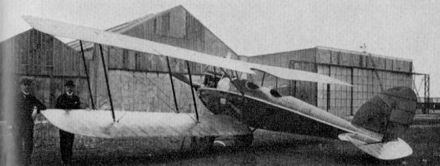
D.F.W. F 37
Euler B II
Produced by the Euler-Werke at Frankfurt at the end of 1914, the B II was little more than a copy of the L.V.G. machine. An earlier version, the B I, had a tricycle undercarriage. Engine, 100 h.p. Mercedes D I. Span, 14.5 m. (47 ft. 7 in.). Area, 40 sq.m. (432 sq.ft.). Weights: Empty, 757 kg. (1,665 lb.). Loaded, 1,172 kg. (2,578 lb.). Speed, 120 km.hr. (75 m.p.h.). Climb, 3.000 m. (9,840 ft.) in 29 min. Duration, 4 hr.
Produced by the Euler-Werke at Frankfurt at the end of 1914, the B II was little more than a copy of the L.V.G. machine. An earlier version, the B I, had a tricycle undercarriage. Engine, 100 h.p. Mercedes D I. Span, 14.5 m. (47 ft. 7 in.). Area, 40 sq.m. (432 sq.ft.). Weights: Empty, 757 kg. (1,665 lb.). Loaded, 1,172 kg. (2,578 lb.). Speed, 120 km.hr. (75 m.p.h.). Climb, 3.000 m. (9,840 ft.) in 29 min. Duration, 4 hr.
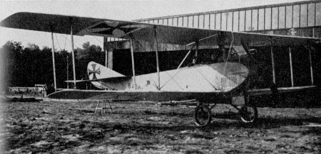
Euler B II
Euler C
Built to the pusher formula, the C was type tested during August 1916 and was armed with two Parabellum machine-guns. Only one machine was built. Engine, 160 h.p. Mercedes D III. Span, 14.8 m. (48 ft. 6 3/4 in.). Length, 9.3 m. (30 ft. 6 1/8 in.). Height, 3.2 m. (10 ft. 6 in.). Area, 52.6 sq.m. (568 sq.ft.). Weights: Empty, 492 kg. (1,082 lb.). Climb, 3.000 m. (9,840 ft.) in 44 min. Duration, 4 hr.
Euler
An experimental single-seat pusher design powered with 160 h.p. Mercedes D III engine. No details available.
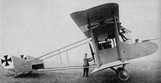
Euler C
Euler D I
Provided as a Nieuport copy at the request of the German authorities, only comparatively few Euler D Is were built, and they were used for training. Type Tested December 1916. Engine, 80 or 100 h.p. Oberursel U O or U I rotary. Span, 8.1 m. (26 ft. 7 in.). Length, 7.12 m. (23 ft. 4 3/8 in.). Height, 2.66 m. (8 ft. 8 3/4 in.). Weights: Empty, 380 kg. (836 lb.). Loaded, 600 kg. (1,320 lb.). Climb, 2,000 m. (6,560 ft.) in 12.5 min.
Euler D II
A development of D I, with parallel-chord wings having single spars. Type Tested December 1916. Only one example built. Engine, 100 h.p. Oberursel U I rotary. Span, 7.47 m. (24 ft. 6 1/8 in.). Length, 5.94 m. (19 ft. 5 7/8 in.). Height, 2.75 m. (9 ft. 0 1/4 in.). Weights: Empty, 380 kg. (836 lb.). Loaded, 615 kg. (1,353 lb.). Speed, 145 km.hr. (90.625 m.p.h.). Climb, 2,000 m. (6,560 ft.) 9.5 min. Duration, 1 1/2 hr.
Euler D
Obviously a 160 h.p. Mercedes D III development of the Euler D II, but the D III designation has not been confirmed. No details.
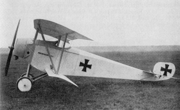
Euler D I
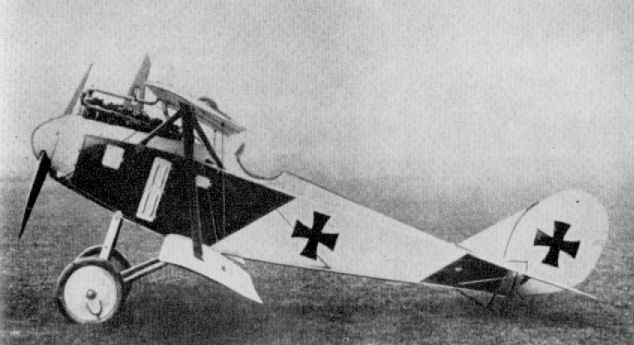
Euler D
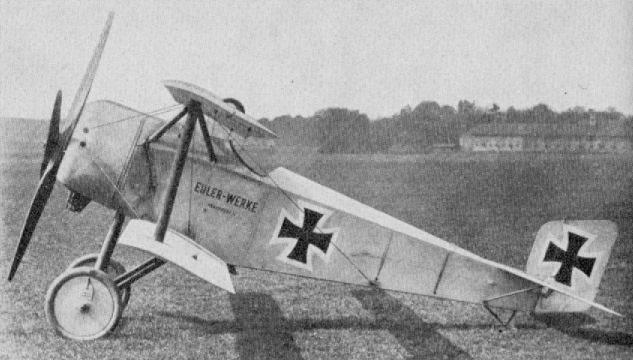
Euler D II
Euler Dr 1
The first Euler triplane, powered with 160 h.p. Oberursel U III. No data. The designation was not official, neither is it completely certain.
Euler Dr 2
Another experimental triplane powered with 160 h.p. Mercedes D III engine. No data. The designation was not official.
Euler Dr 3
Further experimental triplane, a development of Dr 2 fitted with 100 h.p. Oberursel U I engine. No data. The designation was not official.
Euler Dr 4
This triplane emerged from the Euler-Werke in 1916 and was an extremely ungainly aircraft intended for training duties and featuring side-by-side seating arrangement. Engine, 220 h.p. Mercedes D IV with reduction gears. Span, 10.0 m. (32 ft. 9 3/4 in.). Length, 8.0 m. (26 ft. 3 in.). Height, 3.1 m. (10 ft. 2 in.). Area, 37.5 sq.m. (405 sq.ft.). The designation was not official.
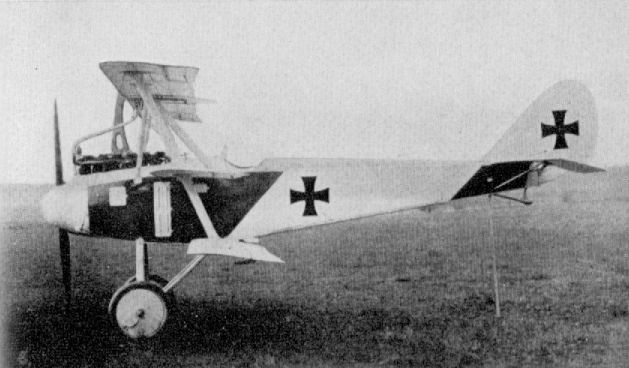
The only prototype Euler Dr 3 (Euler Dr 2 ???) was powered by a 160 hp Mercedes D.III.
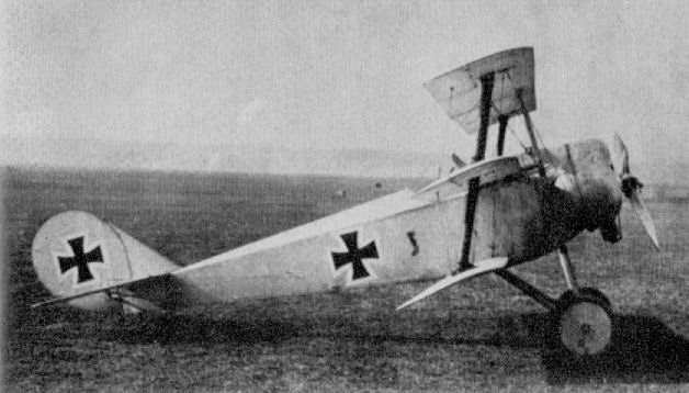
Euler Dr 3
Euler Quadruplane
The designation of quadruplane (vierdecker) was something of a misnomer, for the top surfaces were, in fact, full-span ailerons, although the machine was later modified and normal ailerons fitted. Engine, 100 h.p. Oberursel U I. Area, 46.175 sq.m. (498.7 sq.ft.). Weights: Empty, 883.5 kg. (1,844 lb.). Loaded, 1,383.5 kg. (3,044 lb.).
The designation of quadruplane (vierdecker) was something of a misnomer, for the top surfaces were, in fact, full-span ailerons, although the machine was later modified and normal ailerons fitted. Engine, 100 h.p. Oberursel U I. Area, 46.175 sq.m. (498.7 sq.ft.). Weights: Empty, 883.5 kg. (1,844 lb.). Loaded, 1,383.5 kg. (3,044 lb.).
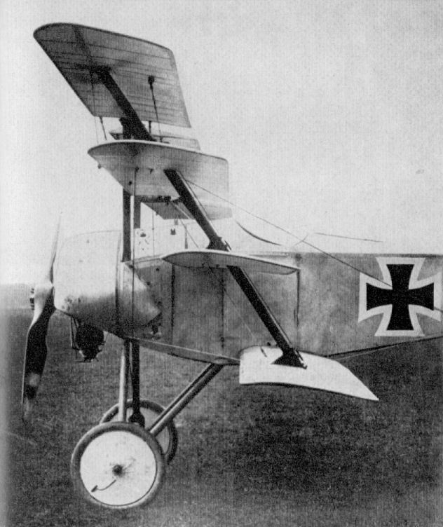
Euler Quadruplane
Fokker M 6
Although the wing was raised, this modified M 5 airframe could not be strictly classed as parasol, as rear spar was fastened to the upper longerons. The M 6 was a two-seater which appeared in June 1914, and the single prototype was subsequently destroyed in a fatal crash. Engine, 80 h.p. Oberursel U O rotary.
Fokker M 8
The M 8 was the production version of the unfortunate M 6. The wing was in the same position, although the forward decking was extended up to the front spar. The fuselage sides were cut away at the cockpit area to give improved downward visibility. First built in September 1914, some thirty machines were supplied (military designation A I) and used on artillery spotting duties. Engine remained 80 h.p. Oberursel, although some sources credit the 100 h.p. engine from that factory.
Fokker M 5 K
This aircraft was a pre-war design and a shorter-span version of the M 5 (the K indicating Kleine Spannweite - small span). A few machines of the type passed into military service as single-seat scouting monoplanes and were retrospectively designated A III. It was this type, subsequently armed, which became the E I. Power unit was 80 h.p. Oberursel U O.
Fokker M 5 L
With longer-span wings, the M 5 L featured three bracing cables per wing panel. A small number were built and used on scouting and reconnaissance duties, these machines receiving the retrospective military designation AII. Usage continued only a few months into 1915. Engine, 80 h.p. Oberursel U O .
Fokker M 5 K/MG
Illustrating the mounting of Parabellum machine-gun for ground testing of synchronisation gear in April 1915. Only one airframe so fitted, before production as E I, and may not have been flown.
Fokker E Series
One of the first German aircraft of the First World War to achieve a much publicized degree of notoriety was the E type Fokker monoplane, of which the E.III version became the main model. The success of the Fokker monoplanes, which reached its peak in the winter of 1915-16, was largely due to their being the first single-seaters equipped with a synchronized machine-gun of reasonable reliability, coupled with a good degree of maneuverability. Other inventors (such as Franz Schneider) had had the idea of a forward-firing fixed machine-gun, synchronized to fire between the airscrew blades, but Anthony Fokker was the first to convince the German authorities of the practicability of his own gear, which he had installed in one of his M 5k (A III) monoplanes previously used for unarmed reconnaissance.
The E.I was powered with a seven-cylinder Oberursel U 0 rotary engine of 80 h.p. It was sent for operational assessment in the summer of 1915 and demonstrated by Fokker himself who - whatever his other shortcomings was undoubtedly a brilliant exhibition pilot. Oswald Boelcke subsequently flew an E.I (E 3115) and is reported to have brought down a French machine on his third sortie. The machine was also tried with equal success by Max Immelmann.
An improved, slightly stronger version was put in hand for the main production series, and was known as the E.II. This entered service in September 1915. However, no more than twenty-three examples were built before detail alterations were made and the designation changed to E.III, the 100 h.p. Oberursel U I engine being common to both types. Boelcke's E.III was serialled 37/15. As far as can be ascertained, between 120 and 150 machines of this version were built. In April 1916 about 110 E.IIIs were operating on the Western Front. Stemming from a pre-war design that had never been intended for combat use, the Fokker monoplanes relied mainly on tactical surprise, and in this achieved much success. Their unsuspecting victims, seeing the enemy approaching from the rear, did not expect him to be able to fire through his airscrew and thereby destroy them. They were soon to learn the error of their judgment, and for a few months, during the latter half of 1915 and early 1916, the Fokkers reaped a grim harvest of unarmed, or poorly armed, Allied machines. Especially unfortunate were the British B.E. types with the observer in the front cockpit, where there was scant opportunity for defense - indeed, they became to be unhappily described as "Fokker Fodder". However, apart from the successful machine-gun installation, the shortcomings of its adversaries undoubtedly contributed towards what eventually became the Fokker legend.
At first the Fokker monoplanes were not envisaged as an offensive weapon, but only for defense of their own two-seaters, and for this purpose were allocated - usually two aircraft - to Fl. Abt. units. At the time of introduction both Boelcke and Immelmann were with Fl. Abt. 62, and it was on 1st August 1915 that the latter scored his first victory flying an E.I, when his airfield was attacked by hostile aircraft. It was Immelmann who set the style of using the Fokker offensively by taking off on "roving commission" patrols and stalking the Allied machines that ventured across the German lines. He evolved the tactic of diving upon the enemy - from out of the sun if possible - rapidly closing for a quick burst, then back with the stick and a swift kick on the rudder-bar as the Fokker neared the vertical, producing a neatly executed reversal of direction without loss of height and readiness for another attack. It was only a matter of time for this maneuver to become known, as it is still known, as an Immelmann Turn.
Inevitably the Fokker monoplanes were eclipsed as Allied designers evolved practical synchronizing gears (as they were literally forced to do) to neutralize the advantage of the Fokker. However, it may be said that the foundations of aerial fighting tactics were laid by the Fokker monoplanes and remained valid for many years to come.
The E.I/E.IV monoplanes were of composite steel and wood construction, and bore an extraordinary degree of resemblance to the French Morane Saulnier monoplanes in both structure and appearance. The fuselage was completely fabricated from welded steel tube, with small brackets welded into the corners of the bays to form anchorages for the bracing cables, which were looped round them and joined with a single turnbuckle. Terminating in a horizontal knife-edge, the fuselage was completely slab sided except for two metal cowling panels at the sides of the extreme nose, which continued the circular section of the cowl for a short distance, and for a rounded top decking extending as far aft as the cockpit, also of sheet metal. The horseshoe-shaped cowling was cut away in the lower segment as a precaution against the accumulation of petrol, which might have drained through the valves and caught fire. The comma rudder and trapezoidal-shaped elevators were of the "all-moving" variety, with no fixed fin surfaces, and demanded continual vigilance from the pilot.
Of parallel chord, the wings were angularly raked at the tips and were a quite flexible structure built on two I-section main spars. The ribs were of poplar, thin in section to afford the degree of flexibility necessary for the warp-type lateral control that was used in the design. The bracing of the wings was by four cables to each panel, anchored to an upper and lower pylon and to the forward main spar. A similar number of cables for lateral control were anchored to the rear spar but ran over pulleys at the apices of the pylons and thence into the cockpit, where they were connected to the control stick.
The undercarriage was a somewhat complex steel-tube structure which also incorporated the lower cable anchorage pylons; the elastic-cord shock absorbers were attached to the tops of the main vertical members inside the fuselage. An inverted pylon of light-gauge steel tube supported the tailskid and also served as a pivot for the lower extremity of the rudder.
Description: Single-seat escort fighting scout.
Manufacturer: Fokker Flugzeug-Werke G.m.b.H. (Fok.).
E.I E.II E.III
Power Plant: 80 hp Oberursel 100 hp Oberursel 100 hp Oberursel
Dimensions:
Span 8.53m ( 28 ft.) 9m (29.5 ft.) 10m (32 ft. 8 in.)
Length 6.76m (22 ft. 2 in.) 7.3m (23.9 ft.) 7.16m (23 ft. 6 in.)
Height 2.89m (9 ft. 6 in.) 2.89m (9 ft. 6 in.) 2.29m (7 ft. 10 in.)
Weights:
Empty 357.4 kg ( 788 lb.) 399 kg ( 878 lb.) 398.2 kg (878 lb.)
Loaded 662 kg (1,239 lb.) 560 kg (1,232 lb) 608.7 kg ( 1,342 lb.)
Performance:
Max speed 131.9 kph ( 82 mph ) 140.8 kph ( 87.5 mph) 140.8 kph ( 87.5 mph)
Ceiling 3,048m (10,000 ft.) 4,114.8m (13,500 ft.) 4,114.8m (13,500 ft.)
Armament: one forward firing one forward firing one forward firing
7.92mm machine gun 7.92mm machine gun 7.92mm machine gun
Fokker M 7
With a sesquiplane (1 1/2-wing) layout, the remainder of the machine was virtually M 5, with necessary lengthening of the fuselage to accommodate the two crew members, the pilot sitting in front. Production was from January 1915, and twenty machines were built, some being used by the German Naval shore stations. Engine, 80 h.p. Oberursel U O.
Fokker M 10 E
A similar machine to the earlier M 7, but with modification to the undercarriage and centre-section struts. The "E" suffix to the factory designation indicated Einstielig - or single-bay - to differentiate from the two-bay M 10 Z which also existed. A few aircraft of this type were supplied to Austro-Hungarians, who designated it B I. Engine, 80 h.p. Oberursel U O.
Fokker M 10 Z
Differed from M 10 E in being two-bay aircraft - Z suffix indicating Zweistielig - also the more powerful 100 h.p. Oberursel U I engine was installed. A small number of the type was supplied to Austro-Hungarian air force, who designated it B II.
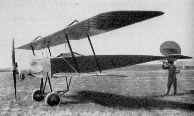
Fokker M 7
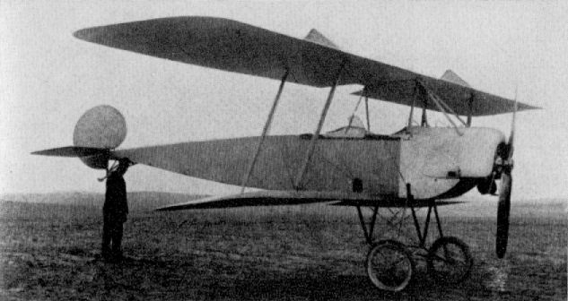
Fok B.I (M10E) (1915)
Fokker E Series
Mention must be made of the E.IV (of which some thirty examples were produced), a last-ditch effort on Fokker's behalf to prolong active life when the type was obsolescent, since the legend of the Fokker's invincibility had been shattered by the spring of 1916. The E.IV was virtually an enlarged E.III fitted with two machine-guns and with a 160 h.p. Oberursel U III engine. This was a fourteen-cylinder, two-row, rotary and had not the reliability, or flexibility, of the less powerful rotaries. Due to its weight it made the E.IV far less nimble than the E.II and E.III. Immelmann had one which had been especially equipped with three machine-guns, but performance was so poor, due to the increased weight, he reverted to the E.III, on which type he was eventually killed on 18th June 1916 during combat with an F.E. 2b of 25 Sqdn. R.F.C., flown by Lieut. G. R. McCubbin and his observer Cpl. J. H. Waller. However, Oblt. Student of Fokkerstaffel der III Armee (later on Jasta 9) preferred the E.IV to the E.III and operated with success in the Verdun sector.
The E.I/E.IV monoplanes were of composite steel and wood construction, and bore an extraordinary degree of resemblance to the French Morane Saulnier monoplanes in both structure and appearance. The fuselage was completely fabricated from welded steel tube, with small brackets welded into the corners of the bays to form anchorages for the bracing cables, which were looped round them and joined with a single turnbuckle. Terminating in a horizontal knife-edge, the fuselage was completely slab sided except for two metal cowling panels at the sides of the extreme nose, which continued the circular section of the cowl for a short distance, and for a rounded top decking extending as far aft as the cockpit, also of sheet metal. The horseshoe-shaped cowling was cut away in the lower segment as a precaution against the accumulation of petrol, which might have drained through the valves and caught fire. The comma rudder and trapezoidal-shaped elevators were of the "all-moving" variety, with no fixed fin surfaces, and demanded continual vigilance from the pilot.
Of parallel chord, the wings were angularly raked at the tips and were a quite flexible structure built on two I-section main spars. The ribs were of poplar, thin in section to afford the degree of flexibility necessary for the warp-type lateral control that was used in the design. The bracing of the wings was by four cables to each panel, anchored to an upper and lower pylon and to the forward main spar. A similar number of cables for lateral control were anchored to the rear spar but ran over pulleys at the apices of the pylons and thence into the cockpit, where they were connected to the control stick.
The undercarriage was a somewhat complex steel-tube structure which also incorporated the lower cable anchorage pylons; the elastic-cord shock absorbers were attached to the tops of the main vertical members inside the fuselage. An inverted pylon of light-gauge steel tube supported the tailskid and also served as a pivot for the lower extremity of the rudder.
Description: Single-seat escort fighting scout.
Manufacturer: Fokker Flugzeug-Werke G.m.b.H. (Fok.).
E.IV
Power Plant: 160 hp Oberursel
Dimensions:
Span 9.75m (32 ft. 1 in.)
Length 7.46m (24 ft. 8 in.)
Height 2.89m (9 ft. 1 in.)
Weights:
Empty 465 kg (1,025 lb.)
Loaded 722.6 kg ( 1,593 lb.)
Performance:
Max speed 160.9 kph ( 100 mph)
Ceiling 4,114.8m ( 13,500 ft.)
Armament: two forward firing
7.92mm machine gun
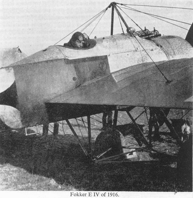
Otto Parschau glares out from the confines of Fok. E.IV 122/15's enclosed cockpit. (Lance Bronnenkant)
Fokker M 9 (K1)
April 1915 saw the appearance of the M 9, the only twin-engined Fokker aircraft of the First World War. The twin fuselages were modified M 8s, each with its own tail surfaces, there being no rigid connecting surface aft. The central nacelle housed a crew of three, and 80 h.p. Oberursel rotaries were mounted at either end. The Kl designation implied Kampfflugzeug but was soon modified to the G classification. Only one M 9 was built, and relatively few flights were made.
April 1915 saw the appearance of the M 9, the only twin-engined Fokker aircraft of the First World War. The twin fuselages were modified M 8s, each with its own tail surfaces, there being no rigid connecting surface aft. The central nacelle housed a crew of three, and 80 h.p. Oberursel rotaries were mounted at either end. The Kl designation implied Kampfflugzeug but was soon modified to the G classification. Only one M 9 was built, and relatively few flights were made.
Fokker W 4
This aircraft was a seaplane development of the M 7 which had also been used by the German Navy. Only a few short flights were made during March 1915. Engine was 80 h.p. Oberursel U O rotary.
This aircraft was a seaplane development of the M 7 which had also been used by the German Navy. Only a few short flights were made during March 1915. Engine was 80 h.p. Oberursel U O rotary.
Fokker M 16 E
A single-bay two-seater of 1915 with fuselage completely filling gap. Only one aircraft built, powered with 120 h.p. Mercedes D II. The somewhat lengthy wingtip skids are unusual.
Fokker M 16 Z
A larger and more powerful aircraft, the two-bay M 16 Z was almost a complete re-design from the M 16 E. The first version was fitted with 160 h.p. Mercedes engine, but a small production order of thirty aircraft for the Austro-Hungarians had the 200 h.p. Austro-Daimler motor installed. These machines also dispensed with the somewhat outdated warp system of lateral control and had overhung balanced ailerons. They were armed with one Schwarzlose for the observer and a similar gun firing forward for the pilot.
Fokker M 18 z
Prototype of machine which, after modification of tail surfaces, became the D I. Engine, 120 h.p. Mercedes D II.
Fokker D I and IV
With the eclipse of the E type monoplanes, the Fokker establishment brought forth its D I biplane in the summer of 1916. Evolved from a series of prototypes designed by Martin Kreutzer, it was an uninspired and singularly mediocre aeroplane and only passed into comparatively limited production, because little else was available to replace the outdated E III on the Western Front.
Developed from the M 18 prototypes, the D I was the production version of the M 18z, the "z" indicating zweistielig (i.e. two-strutter, or two-bay). Being a two-bay biplane spanning some 30 ft., with only a 120 h.p. Mercedes D II engine, it was decidedly under-powered as a single-seat fighting machine. However, due largely to lack of any stiff opposition, it managed to give a reasonable account of itself, sufficient at least to impress the authorities (reinforced no doubt by Fokker's persuasive volubility) to place production orders for the type.
On the Western Front the D I soon began to encounter doughtier opponents, and could not compete in manoeuvrability and climb with the lighter and more nimble rotary-engined Nieuports the Allies were bringing into use. Hence it soon fell into disrepute with the pilots who had to fly it, and it was relegated to the Eastern Front and to non-operational duties. Some machines were sold to the Austro-Hungarian authorities. In a final endeavour to extract the utmost use from the type, Fokker slightly modified and enlarged it and re-engined it with the 160 h.p. Mercedes D III, in which guise it was designated D IV (M 21). Performance increase, however, was only marginal, and the engines could be - and were - put to much better use by the Albatros firm in their D I type.
There was nothing unconventional about the D I; it was an orthodox two-bay biplane. The fuselage followed the same style of welded steel-tube construction as in the E type monoplanes, braced in all planes with stranded cables to form a rigid-braced box-girder structure. The nose section had to be completely re-worked to accommodate the six-cylinder in-line motor, which was quite neatly enclosed within somewhat bulbous metal panels, with just the fore part of the cylinder block remaining exposed, which facilitated servicing. The cooling system consisted of two long, narrow, "honey-combed" radiator boxes on either side of the nose, adjacent to the leading edge of the wings. Aft of this point the fuselage was fabric covered and tapered to a horizontal knife-edge. Although slightly different in size and area, the complete empennage was identical to that of the E types in both profile and proportion: again there were no fixed fin surfaces.
The wings were of straightforward parallel-chord layout, of equal span and with a slight angular rake to the tips. The upper wing was sited quite close to the fuselage on short steel-tube centre-section struts which were welded direct to the longerons. A peculiar feature on the centre-section was the raising of the line of the leading edge. A large angular cut-out in the trailing edge, together with the wing at approximately eye level, gave the pilot an excellent field of forward and upward vision. Interplane struts were of circular steel tube faired off with wooden fairings: the middle of the inboard rear struts was "notched out" to allow passage of the warp control wires, which passed over pulleys on the rear centre-section struts and so down to the control stick.
The undercarriage was a conventional vee-type chassis of steel tube with wooden fairings, and sprung with elastic shock cord. The wooden tailskid was hinged to an inverted tubular pylon which also served as a pivot anchorage for the lower extremity of the rudder.
With the installation of the 160 h.p. Mercedes D III power plant and a slight increase in overall dimensions, the D IV had an improved performance and the level speed increased slightly, but it still lacked the manoeuvrability expected of a fighter. As the Albatros D types became available in increasing numbers, the Fokker D Is and IVs lapsed into the obscurity of non-operational duties with the Fliegerschulen (Flying Schools). Total production of D I was twenty-live and of D IV thirty-three.
With the formation of the Jagdstaffeln in the summer of 1916 the majority were inevitably equipped with a heterogeneous collection of single-seaters transferred from the escort duties with the various Fl. Abt. units. One such to have some Fokker biplanes on its establishment was Jasta 2 and Leut. Grafe from this unit was surprised in a D I by Capt. Albert Ball, V.C., on 21st September 1916, when he closed with it among clouds some 5,000 ft. over the Bapaume Cambrai road. He was able to approach, apparently completely unobserved, and put in an attack from below at exceedingly close range. He plainly saw his tracers entering the Fokker in the region underneath the engine and pilot's seat, and the machine disappeared into the clouds in a side-slipping dive. The subsequent crash was not observed, and Capt. Ball was not credited with this victory. However, it was eventually established that the Fokker did crash about a kilometre east of Bapaume and that the pilot was killed.
TECHNICAL DATA
Description: Single-seat fighting scout.
Manufacturer: Fokker Flugzeug-Werke G.m.b.H. (Fok.).
Power Plant:
One 120 h.p. Mercedes D II 6 cylinder in-line water-cooled engine (D I).
One 160 h.p. Mercedes D III 6 cylinder in-line water-cooled engine (D IV).
Dimensions:
Span, 9.05 m. (29 ft. 8 3/8 in.). Length, 5.7 m. (18 ft. 8 1/2 in.). Height, 2.25 m. (7 ft. 4 5/8 in.). Area, 22 sq.m. (238 sq.ft.). ( D.I.)
Span, 9.7 m. (31 ft. 10 in.). Length, 6.3 m. (20 ft. 8 in.). Height. 2.45 m. (8 ft. 0 1/2 in.). Area, 21 sq.m. (227 sq.ft.). (D IV.)
Weights:
Empty, 463 kg. (1,019 lb.). Loaded, 671 kg. (1,476 lb.). D I.
Empty, 606 kg. (1,333 lb.). Loaded, 841 kg. (1,850 lb.), D IV.
Performance: Maximum speed, 150 km.hr. (93-75 m.p.h.), D I; 160 km.hr. (100 m.p.h.), D IV. Initial climb, 1,000 m. (3,280 ft.) in 5 min., D I; 1,000 m. (3,280 ft.) in 3 min., D IV. Duration, 1 1/2 hr.
Armament:
D I one fixed Spandau machine-gun forward.
D IV two fixed Spandau machine-guns forward. (Usually not more than one gun was fitted to obtain improved performance.)
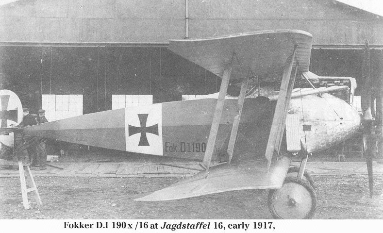
Unavoidably, a wing strut prevents complete identification of the military number of this Jasta 16 D.I photographed at Ensisheim airfield.
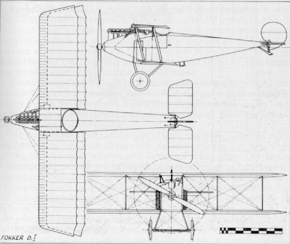
Fokker M 17 E/1
This single example of the M 17 E/1 was built at the end of 1915. The configuration is similar to that of the M 16 E, although this aircraft was a single-seater. The "crash pylon" structure to prevent the pilot being decapitated in a nose-over landing may be noted, also the cutting away of the cockpit sides to improve visibility. Power unit was 100 h.p. Oberursel U I. Armament, one Spandau machine-gun.
Fokker M 17 E/2
With the fuselage modified to incorporate a normal centre-section strut system, the M 17 E/2 was a more orthodox-looking aeroplane. Tail surfaces were later revised to the characteristic comma-rudder profile, and in this guise a few machines were used by Austro-Hungarians in an unarmed scouting capacity, designated B III. The M 17 Z became the D II. Engine, 80 h.p. Oberursel U O. Armament, one Spandau machine-gun.
Fokker D.II
Although apparently later than the D.I (M 18z) in order of factory numerical sequence, the Fokker D.II would in fact appear to have preceded it, having been evolved from the M 17z prototype, from which it differed mainly in the rudder shape.
Appearance of the D.II during 1916 was before the establishment of the Jagdstaffeln, and it was issued to the Fl. Aht. units as a replacement for the E.II and E.III monoplanes used in escort and protection duties, and as such did not form the exclusive equipment of any unit. Even later in the summer of that year, when the Jastas came into being, Fokker D.IIs, and the subsequent D.III, together with Halberstadt D.II and D.III, only formed partial equipment of the first units to be formed.
The airframe of the D.II was very similar to that of the D.I, being slightly smaller in span but greater in length. With the 100 h.p. Oberursel U I rotary engine, the D.II was a considerably lighter machine and in consequence more maneuverable, although its speed and climb performance showed no great improvement.
The fuselage was closely akin to that of the E type monoplanes; of welded steel-tube frame braced in all bays with stranded cables to form a rigid box girder, the slab-sides tapering to a horizontal knife-edge. The decking forward of the cockpit was rounded to the same radius as the horseshoe shaped cowl, which component had short extension cowlings fitted to its trailing edge blending into the fuselage sides. The same style of comma rudder and trapezoidal tailplane, with no fixed fin surfaces, as used on the E types, was preserved.
Again of two-bay layout, the wing structure was nearly identical to that of the D.I, being only slightly reduced in span. Wing warping was still retained as the method of lateral control. Built of two box-spars, the wings were necessarily a flexible structure, although a determined effort to preserve a reasonable wing section was made by the introduction of no less than three false nose ribs between each main rib.
The undercarriage raked forward considerably from the lower wing leading-edge point and gave the aircraft a peculiar attitude when on the ground; it was made up of three steel tubes in each vee, two forward and one aft. The usual straight-through axle was mounted between the two forward tubes which allowed it upward movement on the elastic-cord shock absorbers when they were under tension. The usual pylon-type combined tailskid and rudder anchorage was welded at the extreme rear.
Description: Single-seat fighting scout
Manufacturer: Fokker Flugzeug-Werke G.m.b.H. (Fok)
D.II
Power Plant: 100 h.p. Oberursel U.I
9 cylinder rotary engine
Dimensions:
Span 8.75 m. (28 ft. 8 1/2 in.)
Length 6.4 m. (21 ft. )
Height 2.55 m. (8 ft. 4 3/8 in.)
Area 18 sq.m. (194 sq.ft.)
Weights:
Empty 384 kg. (844.8 lb.)
Loaded 576 kg. (1,267.2 lb.)
Performance:
Max speed 150 km.h. (93.75 m.p.h.)
climb to
1,000 m. 4 min.
4,000 m. 24 min.
Duration 1 1/2 hr.
Armament: One fixed Spandau machine-gun
synchronized to fire
through airscrew
Fokker M 17 z (versuchs)
An experimental version of the D II with additional stringers rounding out fuselage lines and large spinner fitted. Engine, 100 h.p. Oberursel U I.

Fokker D II 231/16.
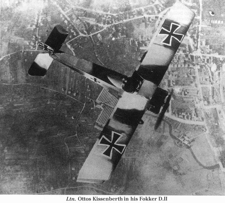
Leutnant Otto Kissenberth in his Fokker D.II.
A rare air-to-air photograph of a Fokker D II biplane scout of 1916.
A rare air-to-air photograph of a Fokker D II biplane scout of 1916.
Fokker D.III
In an endeavor to improve performance, Martin Kreutzer strengthened the fuselage of the D.II to take the 160 h.p. Oberursel U III twin-row rotary engine and, in view of the additional weight this incurred, married it to a D.I wing cellule to take advantage of its greater area. This machine became the D.III (M 19). However, results were still not up to expectations, as the basic design of the whole D.I to D.IV series was little more than indifferent and the U III engine continued to be as unreliable as it had been in the E.IV monoplane.
Visually the D.III differed little from the D.II. It could be identified by the deeper chord of the cowling, in the front of which extra cooling slots were fretted, and also a forward "spider" engine mounting incorporated. To allow for the additional nose weight, the undercarriage was modified and the forward struts assumed a more orthodox angle, now being secured at the base of the rear engine bearer plate.
The D.III's operational life was brief, as its performance was quickly outclassed by the Albatros and Halberstadt scouts which equipped the first Jagdstaffeln. However, it was flown for a short time by such famous pilots as Richthofen, Boelcke and Udet.
When flying a D.III (No. 364/16), Ernst Udet resorted to a little novel subterfuge by installing a dummy observer aft of the pilot's cockpit on the rear decking to mislead adversaries into thinking there might be a "sting in the tail", and thereby discourage attacks from the rear. Udet's D.III also had a stringer clipped along the middle of the fuselage sides (as did some others), which relieved the monotony of the slab-sides, although it is doubtful if it served any useful aerodynamic purpose. A D.III used by Oswald Boelcke, D.III 352/16, in which he recorded his twentieth victory, was preserved and exhibited in the Zeughaus Berlin, until it was unfortunately destroyed in a bombing raid in 1943. Boelcke also flew the D.III 356/16.
Some D. IIIs later used for school work, and also some examples sold to the Dutch authorities, were fitted with balanced ailerons. The total production of all D.II and D.III types was some 291 machines; the findings of the Inter-Allied Commission set up after the war recorded the collective total of D.I to D.IV machines serving at the Front in the autumn of 1916 as being 100 aircraft. Modifications of most of these types were supplied to the Austro-Hungarian forces, with whom Anthony Fokker also conducted considerable business.
Description: Single-seat fighting scout
Manufacturer: Fokker Flugzeug-Werke G.m.b.H. (Fok)
D.III
Power Plant: 160 h.p. Oberursel U.III
14 cylinder two-row rotary
Dimensions:
Span 9.05 m. (29 ft. 8 3/8 in.)
Length 6.3 m. (20 ft. 8 in.)
Height 2.25 m. (7 ft. 4 5/8 in.)
Area 20 sq.m. (216 sq. ft.)
Weights:
Empty 452 kg. (994.4 lb.)
Loaded 710 kg. (1,562 lb.)
Performance:
Max speed 160 km.h. (100 m.p.h.)
climb to
1,000 m. 3 min.
4,000 m. 20 min.
Duration 1 1/2 hr.
Armament: One or two fixed Spandau machine-guns
synchronized to fire through airscrew
Fokker M 20 z
This experimental version of D III, with more streamlined fuselage and cowling arrangement, was built in July 1916. Engine fitted was 110 h.p. Siemens-Halske Sh I. Armament, twin Spandau machine-guns.
Fokker D I and IV
With the eclipse of the E type monoplanes, the Fokker establishment brought forth its D I biplane in the summer of 1916. Evolved from a series of prototypes designed by Martin Kreutzer, it was an uninspired and singularly mediocre aeroplane and only passed into comparatively limited production, because little else was available to replace the outdated E III on the Western Front.
Developed from the M 18 prototypes, the D I was the production version of the M 18z, the "z" indicating zweistielig (i.e. two-strutter, or two-bay). Being a two-bay biplane spanning some 30 ft., with only a 120 h.p. Mercedes D II engine, it was decidedly under-powered as a single-seat fighting machine. However, due largely to lack of any stiff opposition, it managed to give a reasonable account of itself, sufficient at least to impress the authorities (reinforced no doubt by Fokker's persuasive volubility) to place production orders for the type.
On the Western Front the D I soon began to encounter doughtier opponents, and could not compete in manoeuvrability and climb with the lighter and more nimble rotary-engined Nieuports the Allies were bringing into use. Hence it soon fell into disrepute with the pilots who had to fly it, and it was relegated to the Eastern Front and to non-operational duties. Some machines were sold to the Austro-Hungarian authorities. In a final endeavour to extract the utmost use from the type, Fokker slightly modified and enlarged it and re-engined it with the 160 h.p. Mercedes D III, in which guise it was designated D IV (M 21). Performance increase, however, was only marginal, and the engines could be - and were - put to much better use by the Albatros firm in their D I type.
There was nothing unconventional about the D I; it was an orthodox two-bay biplane. The fuselage followed the same style of welded steel-tube construction as in the E type monoplanes, braced in all planes with stranded cables to form a rigid-braced box-girder structure. The nose section had to be completely re-worked to accommodate the six-cylinder in-line motor, which was quite neatly enclosed within somewhat bulbous metal panels, with just the fore part of the cylinder block remaining exposed, which facilitated servicing. The cooling system consisted of two long, narrow, "honey-combed" radiator boxes on either side of the nose, adjacent to the leading edge of the wings. Aft of this point the fuselage was fabric covered and tapered to a horizontal knife-edge. Although slightly different in size and area, the complete empennage was identical to that of the E types in both profile and proportion: again there were no fixed fin surfaces.
The wings were of straightforward parallel-chord layout, of equal span and with a slight angular rake to the tips. The upper wing was sited quite close to the fuselage on short steel-tube centre-section struts which were welded direct to the longerons. A peculiar feature on the centre-section was the raising of the line of the leading edge. A large angular cut-out in the trailing edge, together with the wing at approximately eye level, gave the pilot an excellent field of forward and upward vision. Interplane struts were of circular steel tube faired off with wooden fairings: the middle of the inboard rear struts was "notched out" to allow passage of the warp control wires, which passed over pulleys on the rear centre-section struts and so down to the control stick.
The undercarriage was a conventional vee-type chassis of steel tube with wooden fairings, and sprung with elastic shock cord. The wooden tailskid was hinged to an inverted tubular pylon which also served as a pivot anchorage for the lower extremity of the rudder.
With the installation of the 160 h.p. Mercedes D III power plant and a slight increase in overall dimensions, the D IV had an improved performance and the level speed increased slightly, but it still lacked the manoeuvrability expected of a fighter. As the Albatros D types became available in increasing numbers, the Fokker D Is and IVs lapsed into the obscurity of non-operational duties with the Fliegerschulen (Flying Schools). Total production of D I was twenty-live and of D IV thirty-three.
With the formation of the Jagdstaffeln in the summer of 1916 the majority were inevitably equipped with a heterogeneous collection of single-seaters transferred from the escort duties with the various Fl. Abt. units. One such to have some Fokker biplanes on its establishment was Jasta 2 and Leut. Grafe from this unit was surprised in a D I by Capt. Albert Ball, V.C., on 21st September 1916, when he closed with it among clouds some 5,000 ft. over the Bapaume Cambrai road. He was able to approach, apparently completely unobserved, and put in an attack from below at exceedingly close range. He plainly saw his tracers entering the Fokker in the region underneath the engine and pilot's seat, and the machine disappeared into the clouds in a side-slipping dive. The subsequent crash was not observed, and Capt. Ball was not credited with this victory. However, it was eventually established that the Fokker did crash about a kilometre east of Bapaume and that the pilot was killed.
TECHNICAL DATA
Description: Single-seat fighting scout.
Manufacturer: Fokker Flugzeug-Werke G.m.b.H. (Fok.).
Power Plant:
One 120 h.p. Mercedes D II 6 cylinder in-line water-cooled engine (D I).
One 160 h.p. Mercedes D III 6 cylinder in-line water-cooled engine (D IV).
Dimensions:
Span, 9.05 m. (29 ft. 8 3/8 in.). Length, 5.7 m. (18 ft. 8 1/2 in.). Height, 2.25 m. (7 ft. 4 5/8 in.). Area, 22 sq.m. (238 sq.ft.). ( D.I.)
Span, 9.7 m. (31 ft. 10 in.). Length, 6.3 m. (20 ft. 8 in.). Height. 2.45 m. (8 ft. 0 1/2 in.). Area, 21 sq.m. (227 sq.ft.). (D IV.)
Weights:
Empty, 463 kg. (1,019 lb.). Loaded, 671 kg. (1,476 lb.). D I.
Empty, 606 kg. (1,333 lb.). Loaded, 841 kg. (1,850 lb.), D IV.
Performance: Maximum speed, 150 km.hr. (93-75 m.p.h.), D I; 160 km.hr. (100 m.p.h.), D IV. Initial climb, 1,000 m. (3,280 ft.) in 5 min., D I; 1,000 m. (3,280 ft.) in 3 min., D IV. Duration, 1 1/2 hr.
Armament:
D I one fixed Spandau machine-gun forward.
D IV two fixed Spandau machine-guns forward. (Usually not more than one gun was fitted to obtain improved performance.)
Fokker M 22
This aircraft was a prototype machine which, with revised cowling, became the D V. This was the last design on which Kreutzer worked and the first in which Platz played some part in design.
Fokker D V
Making its debut in September 1916, the Fokker D V was the production version of the M 22 prototype. It was the last of the M series of thin-wing Fokkers. Design work had been initiated by Martin Kreutzer, but with his untimely death the finalisation of the design is thought to have been the work of Reinhold Platz.
Certainly a much improved appearance had been bestowed upon the D V. Although basically only a development of the D III and retaining many of the earlier characteristics, the improved lines paid dividends in increased performance. Although production figures exceeded those of any previous Fokker D types - 216 being built - few Fokker D Vs appear to have seen operational service on the Western Front, although Jasta 6 has been reported as having the type on its establishment, one aircraft with the unit being 2642/16. Undoubtedly, being contemporaneous with the Albatros D I and D II, those more powerful types were preferentially disposed to the fighting units at the Front and the Fokker D V relegated to the training of fighter pilots.
The enclosing of the 100 h.p. Oberursel rotary engine in a completely circular cowling and the fitting of a large, blunt spinner over the airscrew-hub gave a much cleaner nose-entry than with the earlier horse-shoe cowled types. The remainder of the fabric-covered fuselage consisted of a basic box-girder welded from steel tube and wire braced, tapering to a horizontal knife-edge aft. About this were clipped light stringers on the side and top decking, rounding out the fuselage to the circular section of the cowl at the nose and gradually tapering in with a lessening number of stringers towards the tail. Finless tail surfaces followed the tradition of earlier Fokker designs, with slight dimensional adjustments to allow for the alteration of the surface area; the rounded comma rudder and trapezoidal elevators still being of welded steel tube framing with fabric covering.
Departure from previous practice was made in the wing profile and layout, although the type of construction remained the same. The upper wing was mounted in two panels, with some 5° of sweep, to a centre-section supported on steel tube "N" struts. This mounting close to the fuselage and the staggering well forward of the upper wing, together with the large angular centre-section cut-out, gave the pilot an excellent field of view. The wings were built up on twin wooden spars which were cable braced to steel-tube compression members; thin-section ribs were of ply, with fretted lightening holes and softwood capping strips. Two false ribs were positioned between each of the main ribs. Large overhung, balanced ailerons were installed at the upper wingtips and actuated by cables running through the lower wing then vertically up to connect the operating crank. The lower wing was straight, with slightly raked tips, and was of the same construction as the upper component. Trailing edges were of wire which, with the doping and taughtening of the fabric, imparted the characteristic scalloped outline.
The undercarriage chassis was of light-gauge steel tube, with a closely spaced pair of struts forming the front leg and a single tube the rear leg. On some aircraft the two front tubes were faired over to give the appearance of a single leg; on others they were left uncovered. The axle was mounted between these two struts and bound to the apex with elastic cord. The strong ash tailskid was mounted on a small inverted pylon of steel tube which also formed the anchorage of the bottom rudder hinge.
TECHNICAL DATA
Description: Single-seat fighter.
Manufacturer: Fokker Flugzeug-Werke G.m.b.H. Schwerin am Mecklenburg (Fok.).
Power Plant: One 100 h.p. Oberursel U I 9 cylinder rotary.
Dimensions: Span, 875 m. (29 ft. 0 1/2 in.). Length, 605 m. (19 ft. 10 1/4 in.). Height, 2.3 m. (7 ft. 6 1/2 in.). Area, 15.5 sq.m. (167.4 sq.ft.).
Weights: Empty, 363 kg. (797 lb.). Loaded, 566 kg. (1,245 lb.).
Performance: Speed. 170 km.hr. (106.25 m.p.h.). Climb, 3,000 m. (9,840 ft.) in 19 min. Duration, ca. 1 1/2 hr.
Armament: One Spandau machine-gun firing forward. Some aircraft may have had twin guns fitted.
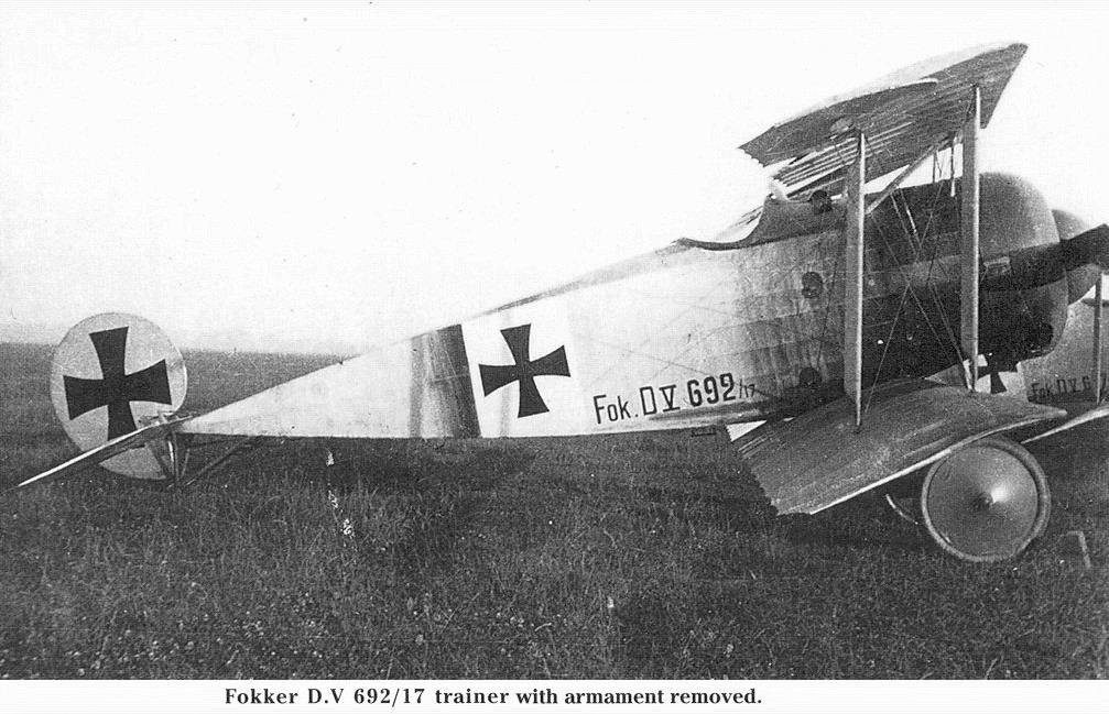
Fokker D V (serial 692/17) trainer with armament removed. The D V was ordered as an advanced trainer, but was issued to some home-based defence units.
Fokker D.V 692/17 was one of the last aircraft from the second batch. Note the shadows of the wing struts and rigging wires cast onto the fuselage by the low-standing sun.
Fokker D.V 692/17 was one of the last aircraft from the second batch. Note the shadows of the wing struts and rigging wires cast onto the fuselage by the low-standing sun.
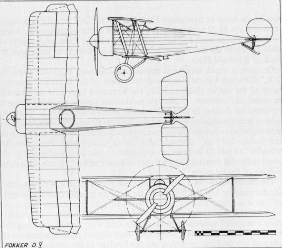
Fokker V 1
The system of designating experimental aircraft with a V prefix was begun in the autumn of 1916, and coincidentally the V 1 was the first aircraft to be completely designed by Reinhold Platz. This was a revolutionary machine with a stocky steel-tube fuselage rounded out to the full circle of the cowling and, although the empennage appeared an orthodox structure, surfaces were "all moving" and featured no fin surfaces. The deep-sectioned wings were fully cantilever and ply-covered: in place of conventional ailerons the whole of each wingtip for a distance of approximately a metre moved differentially for lateral control. Other characteristics, which persisted practically right through the remainder of the Fokkers built during the war, were the lifting surface fairing the axle and spreaders and the steel-tube, pylon type, centre-section struts. Power unit was no more than a 100 h.p. Oberursel U I rotary. Two Spandau machine-guns firing forward were fitted.
Fokker V 2
In January 1917 the V 1 was re-designed with conventional tail surfaces and a 120 h.p. Mercedes water-cooled engine installed. The revolutionary moving wingtips for lateral control were retained.
Fokker V 9
Built in the autumn of 1917, the V 9 again used many of the triplane subassemblies. The lower wing featured the single compound spar as in the Dr 1; the upper wing had two spars. No less than two pyramids of three struts supported the centre-section on either side, making a round dozen struts altogether. Engine was at first 80 h.p. Oberursel U O, but later the 110 h.p. U II was fitted. Span, 7.7 m. (25 ft. 3 1/8 in.). Length, 5.9 m. (19 ft. 4 3/8 in.). Area, 17.1 sq.m. (184.68 sq.ft.). Loaded weight, 580 kg. (1,276 lb.).
Fokker V 13
Two versions of the V 13 were built, one powered with 145 h.p. Oberursel U III and the other (above) with 160 h.p. Siemens-Halske Sh III geared rotary. The type was developed from the earlier V 9, but had a lower wing with two spars and "N" interplane struts. The centre-section struts were also simplified. As may be seen, the Siemens-engined version required a very stalky undercarriage to give the necessary clearance for the large-diameter, slow-revolving (900 r.p.m.) airscrew. The Oberursel-engined model eventually went into small-scale production as the D VI with the lower-powered U II of 110 h.p. installed. At the D types Competition the V 13, at a loaded weight of 668 kg. (1,470 lb.), climbed to 4.900 m. (13,448 ft.) in 19.5 min. on 3rd February 1918 in the hands of test pilot Matthias.
Fokker D VI
During the winter of 1917-18 two rotary-engined prototypes designated V 13/1 and 13/2 were being built in the Fokker works at Schwerin. These aircraft were powered with the new 145 h.p. Oberursel U III and 160 h.p. Siemens-Halske Sh III engines respectively and made their first public appearance when sent to Adlershof for the first of the D type competitions in January 1918. Although both engines were far from trouble-free, the airframe itself was considered promising enough to place a small production order. Production aircraft were, however, to be fitted with the eminently reliable 110 h.p. Oberursel U II, which engine was virtually a straight copy of the French 110 h.p. Le Rhone.
From April 1918 production continued alongside the D VII, but was comparatively slow due to the priority accorded the latter, and when D VI production was terminated in August in order to accelerate D VII supplies, only fifty-nine examples had been built. Of these some seven aircraft were handed over to the Austro-Hungarians, and it has been reported that on these aircraft armament consisted of twin Madschlinger automatic rifles mounted on top of the upper wing, but it seems more likely that they were in fact fitted with Schwarzlose machine-guns. A few D Vis found their way variously to front-line units, one of which was Jasta 84; the remaining machines were used by the fighter-pilot training units.
An intelligence report extract recorded that about 5th August 1918 Jasta 80 received six D VIs, but they could not be used much due to poor quality oil and consequent unreliability of the Oberursel engine.
In design and construction the Fokker D VI was something of a hybrid, be fuselage and tail surfaces stemming from the Dr I and the wings being a scaled-down D VII derivation. The 110 h.p. Oberursel rotary engine was enclosed in a cowling which extended to the lower longerons and which was fitted with a faceplate fretted with two large circular vent holes. The fuselage structure was of welded steel tube which reduced in diameter as it tapered to a vertical knife-edge aft. All bays were braced by a loop of cable joined with a single turnbuckle for tensioning. Triangular sheets of ply, to form a faired profile, were clipped to either side of the nose and extended as far back as the cockpit. The rounded top decking forward of the cockpit was also ply-covered, and another triangular ply panel was clipped aft if the cockpit, and all was then completely covered with fabric. Of steel tube framing, the balanced rudder was of the distinctive comma profile and hinged directly to the sternpost. The triangular tailplane and split, balanced elevators continued the triangular outline and were likewise of steel tube and fabric covered. Two steel struts braced the tailplane to the underside of the fuselage.
In construction, the cantilever wings were greatly similar to those of the D VII. They were based on two hollow box-spars of deep section that tapered towards the tips (the taper being on the lower side only, the top was perfectly flat), on which were threaded the plywood ribs, which were extensively fretted with lightening holes. The leading edge was covered with thin three-ply sheet as far back as the front spar, to which the edge of the ply was tacked. Both wings were in one piece, the spars of the lower wing passing right through the fuselage, as in both the D VII and the earlier Dr I. Overhung, balanced ailerons were fitted to the t op wing only. They were framed from welded steel tube and operated by cables running through the top wing and attaching to control horns: all surfaces were fabric covered. The forward pyramid and single rear centre-section struts were exactly as in the D VII, and likewise of streamlined steel tube. The "N" type interplane struts were also of streamlined steel tube and served largely as ties simply to stop the wings vibrating rather than in any great structural capacity. No cables were used to brace the wings.
With its lifting surface axle fairing, the undercarriage chassis was almost identical to that of the Dr I, although the track was increased considerably to improve ground stability and lessen the tendency to pirouette. The vee struts were of streamlined steel tube, and elastic-cord shock absorbers bound the axle to the cast housing at the apex. An ash tailskid, internally sprung, was fitted just forward of the sternpost.
Although the pilot sat rather below the top wing in the D VI, the wide centre-section cut-out gave a good view from the cockpit. The machine was comparatively fast - faster at low altitude than the D VII - and of good manoeuvrability. If it had not been for the eventual success of the D VIII, it would doubtless have been built in greater numbers.
TECHNICAL DATA
Description: Single-seat fighter.
Manufacturer: Fokker Flugzeug-Werke G.m.b.H. Schwerin am Mecklenburg (Fok.).
Power Plant: One 110 h.p. Oberursel U II 9 cylinder rotary engine.
Dimensions: Span, 765 m. (25 ft. 1 1/4 in.). Length, 6.23 m. (20 ft. 5 3/8 in.). Height, 2.55 m. (8 ft. 4 3/8 in.). Area, 17.7 sq.m. (191 sq.ft.).
Weights: Empty, 393 kg. (865 lb.). Loaded, 583 kg. (1,283 lb.).
Performance: Maximum speed, 196 km.hr (122.5 m.p.h.). Climb, 1,000 m. (3,280 ft.) in 2.5 min., 3,000 m. (9,840 ft.) in 9 min.. 5,000 m. (16.400 ft.) in 19 min. Duration, ca . 1 1/2 hr.
Armament: Two Spandau machine-guns firing forward.
Fokker V 31
V 31 was simply a modified Mercedes-engined two-seater Fokker D VI with towing gear to act as a tug for the V 30. No photograph available.
Fokker V 33
In the summer of 1918 Platz made a partial redesign of the V 9, with a twin-spar lower wing fitted and with unbalanced, high-aspect-ratio ailerons fitted to the upper wing. The rudder at last made a departure from the previous rounded-comma pattern which, either with or without fin, had characterised all Fokker aircraft. The V 33 was a handy little machine which Anthony Fokker himself used as a personal aircraft. He took it back to Holland with him after the war, where it was flown from Schipo as late as 1922. Engine was 110 h.p. Oberursel U II.
Fokker V 11
This was the aircraft that was finally judged the best at the first D types Competition, and eventually, with a little modification, went into production as the D VII. The absence of vertical fin, the narrowness of the undercarriage vees and the shorter fuselage, as compared with the eventual production version, may be noted. The V 11 was powered with the 160 h.p. Mercedes D III engine. At the competition on 25th January 1918, flown by test pilot Grosse at a loaded weight of 874 kg. (1,923 lb.), it climbed to 5,000 m. (16,400 ft.) in 30.7 min. On the following day at 844 kg. (1,857 lb.) weight it took only 25.2 min. to make the climb.
Fokker V 18
Another step in the evolution of the D VII was the V 18, and the increased similarity, compared with the prior V 11, may be noted. A vertical fin was now added to improve directional stability. Power unit was again the 160 h.p. Mercedes D III. After a brief career, this prototype was destroyed in a collision with V 13 during the Fighter Trials at Adlershof. Loaded weight, 861.6 kg. (1,896 lb.). Climb, 1,000 m. (3,280 ft.) in 3 min., 5,000 m. (16,400 ft.) in 28 min. Ceiling, 6,400 m. (20,990 ft.).
Fokker V 21
V 21 was another D VII variant with tapered wings which participated in the second D types Competition in June 1918. It was fitted with a high-compression 160 h.p. Mercedes D III engine. Loaded weight was 853 kg (1,877 lb.), when it climbed to 1,000 m. (3,280 ft.) in 3 min. and to 6,000 m. (19,680 ft.) in 45 min. No photograph available.
Fokker V 22
Combining the best points of the V 11, V 18 and V 21, this machine became production D VII. It is seen here fitted with Jaray type airscrew. Engine, 160 h.p. Mercedes D III. Span, 8.9 m. (28 ft. 2 1/2 in.). Length, 7.0 m. ft. (22 ft. 11 5/8 in.). Height, 2.75 m. (9 ft. 0 1/4 in.). Weights: Empty, 700 kg. (1,540 lb.). Loaded, 850 kg. (1,870 lb.). Speed, 186.5 km.hr. (116.6 m.p.h.). Climb, 1,000 m. (3,280 ft.) in 3.8 min. Duration, 1 1/2 hr. Armament, twin fixed Spandau machine-guns.
Fokker D VII
Following the Triplane into production at the Fokker factory came the D VII, undoubtedly the most famous of all the German fighting scouts of the First World War. The D VII was another product of the fertile brain of designer Reinhold Platz, a figure whose work has become increasingly well known of recent years, mainly due to the researches of the late A. R. Weyl, F.R.Ae.S. Previously Anthony Fokker had managed to claim for himself the design of these machines, largely due to the reticence of Platz, a man without any desire for personal publicity. No doubt Fokker played a part in the evolution of the aircraft, though some of his ideas were wildly fanciful, but it was Platz who managed to bring the practical engineering qualities to bear and produce a worthwhile aeroplane. That Fokker was a brilliant pilot is beyond question, and once he had flown a prototype his flair for knowing instinctively what modifications would improve the machine was a great advantage. It was largely through his flying ability that he was on such good terms with many of the pilots of the German Air Force, particularly Bruno Loerzer.
Forerunner of the D VII was the V 11 prototype. First flights were encouraging, though Fokker discovered that the aircraft needed to be lengthened and required a vertical fin to damp down over-sensitivity, a characteristic which would probably have meant disaster in the hands of a less skilled pilot. After modifications the aircraft was entered in the first of the competitions for D class machines (i.e. single-seat fighting scouts) held at Adlershof airfield in January 1918. The decision of the Front Line pilots, invited to test the machines, was unanimously for the Fokker D VII, and large contracts were awarded to the firm. The irony of the contracts was that Fokker's great rival - Albatros - was ordered to manufacture the D VII under licence at both its Johannisthal factory (Fok. D VII Alb.) and at the Schneidemuhl works (Fok. D VII Oaw.). Each drawing office prepared their own drawings, and no attempt at complete standardisation was made. As a result, although all aircraft looked alike, there were detail differences, and not all components were interchangeable.
As a precaution against failure of steel supply, Albatros built an experimental D VII (541/18) with a wooden fuselage, but circumstances did not require it to go into production. Curiously enough, this aircraft weighed some 40 lb. more than a standard D VII.
The standard D VII was of basically similar construction to the Triplane, using the same formula of wooden cantilever wings and welded steel-tube fuselage. However, the wings differed in having two separate box-spars instead of a single compound spar; they also tapered in depth towards the tips. The same type plywood-covered leading edge and wire trailing edge was retained. A feature shared by the D VII and its Triplane predecessor was the "one-piece" lower wing, which was accommodated by a special cut-out in the lower longerons enabling the spars to go right through the fuselage. The wing was bolted in and a metal panel fitted below to fair off the bottom fuselage contour. Ribs were of three-ply, with narrow flanges tacked all round both sides of the perimeter, forming a sandwich. The top surfaces of the wings were perfectly flat and possessed no anhedral, as has often been shown in the past. The horn-balanced ailerons were of welded steel tube and tapered inversely from root to tip.
The fuselage was a braced box-girder welded from steel tube in the traditional Fokker manner, although forward of the cockpit, the structure became necessarily complex in order to provide adequate strength to support the engine. Metal panels covered the sides back to the leading edge of the lower wing and back to the cockpit on the top decking. Decking aft of the cockpit was in the form of a plywood panel over which the fabric was stretched. The characteristic triangular tailplane and fin, with their large, balanced and rounded, flight controls were also completely fabricated from light-gauge steel tube. All centre-section and interplane struts were of streamlined section steel tube, likewise the undercarriage vees and, as in the Triplane, an aerofoil lifting surface enclosed the axle, spreader bars and elastic-cord shock absorbers. Apart from the metal panels forward, the whole airframe was fabric covered.
Initially, the D VII was fitted with the 160 h.p. Mercedes D III engine, and the car-type radiator represented a new departure for a German production single-seater. Later in 1918 the new 185 h.p. B.M.W. engine went into D VIIs and gave improved performance.
The success of the Fokker D VII was attributable to the fact that it was a fairly easy, yet responsive, machine to fly, with an apparent ability to make a good pilot out of mediocre material; also it retained extreme controllability at its ceiling. With these points went an ability to "hang on its prop" to shoot at an opponent when other machines would have stalled into a spin. One of the first units to be equipped with D VIIs was Geschwader No. 1 (Jastas 4, 6, 10 and 11) in late April 1918, almost immediately after it had lost its legendary commander Baron Manfred von Richthofen, who was killed in a Triplane on 21st April 1918. Throughout the summer of 1918 D VIIs operated in increasing numbers: by early July there were 407 in service and by November a total of 775. The Geschwader No. 2 (Jastas 12, 13, 15 and 19) and Geschwader No. 3 (Jastas 2, 26, 27 and 36) were fully equipped as well as Jastas 5, 7, 8, 14, 16, 20, 22, 23, 24, 28, 29, 30, 32, 35, 37, 40, 44, 45, 46, 47, 48, 49, 51, 52, 53, 54, 56, 57, 58, 59, 66, 69, 71 and 79. These agile machines operated with tremendous success and wrought much havoc; the sight of "straight wings" approaching in a stepped-up gaggle struck anxiety into many a stout-hearted Allied pilot. Such was the regard of the Allied Powers for the capabilities of the Fokker D VII that it was specifically singled out for mention in the Armistice Agreement article which designated items that were to be handed over to the Allies "In erster Linie alle apparate D VII" (especially all first-line D VII aircraft). Some complete, but dismantled, aircraft were "organised" over the border and into Holland by Anthony Fokker, and they continued to be manufactured there and used by the Dutch Air Force until the late 1920s in the Netherlands East Indies.
TECHNICAL DATA
Description: Single-seat fighting scout.
Manufacturers:
Fokker Flugzeug-Werke G.m.b.H. (Fok.).
Albatros Werke G.m.b.H. (Alb.).
Ostdeutsche Albatros Werke, Schneidemuhl (O.A.W.).
Power Plant:
One 160 h.p. Mercedes D III 6 cylinder in-line water-cooled engine.
One 185 h.p. B.M.W. III 6 cylinder in-line water-cooled engine.
Dimensions (Mercedes version): Span, 8.9 m. (29 ft. 3 1/2 in.). Length, 7.0 m. (22 ft. 11 5/8 in.). Height, 2.75 m. (9 ft. 2 1/4 in.). Wing area, 20.5 sq.m. (221.4 sq.ft.).
Weights: Empty, 700 kg. (1,540 lb.). Loaded, 850 kg. (1,870 lb.). Captured aircraft: Empty, (1,622.5 lb.). Loaded, (1,936 lb.).
Performance: Maximum speed, 186.5 km.hr. (116.6 m.p.h.) at 1,000 m.(3,280 ft.). Captured aircraft: 182.5 km.hr. (1141 m.p.h.) at 2,000 m. (6,560 ft.). Climb, 1,000 m. (3,280 ft.) in 3.8 min. (Mercedes), 2.5 min. (B.M.W.); 5,000 m. (16,400 ft.) in 31.5 min. (Mercedes), 16.0 min. (B.M.W.). Captured aircraft: 1,000 m. (3,280 ft.) in 4.25 min. Ceiling, 22,900 ft. Duration, ca. 1 1/2 hr.
Armament: Twin fixed Spandau machine-guns synchronised to fire forward through airscrew.
Fokker V 24
With factory No. F 2612, the V 24 was virtually a standard D VII experimentally fitted with 200 h.p. Benz engine and served as the prototype for the later 185 h.p. B.M.W.-powered production D VII. Span, 8.9 m. (28 ft. 2 1/2 in.). Length, 7.0 m. (22 ft. 11 5/8 in.). Height, 2.75 m. (9 ft. 0 1/4 in.). Loaded weight, 1,006 kg. (2,213 lb.). Climb, 1,000 m. (3,280 ft.) in 3.1 min., 5,000 m. (16,400 ft.) in 23.5 min. Armament, twin fixed Spandau machine-guns.
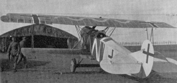
A Fokker D VII captured by No. 84 Squadron of the Royal Air Force.
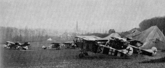
An interesting assortment of markings may be discerned on this group of Fokker D VIIs of Jasta 26, taken late in 1918.
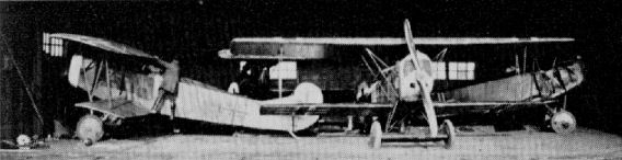
By November 1918 nearly 800 Fokker D VIIs were in service.
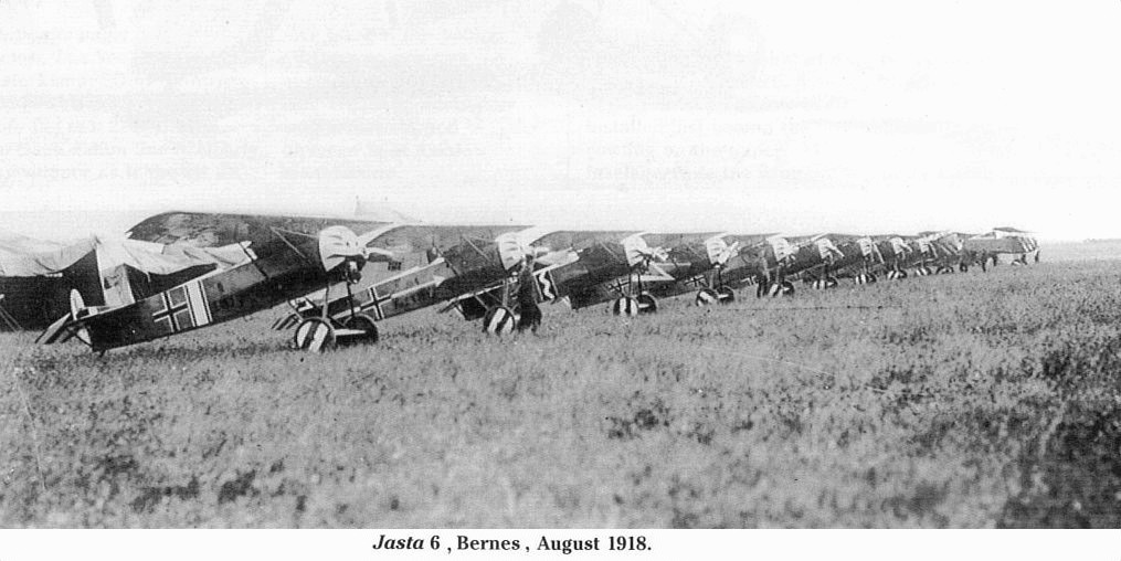
Nine Fokker E.V fighters of Jasta 6 lined up for the camera in early August, with five D.VIIs barely visible at the far end. These photos have previously been identified as having been taken at Bernes but it seems more likely that they were taken at Chambry around 5 August.

Fokker D VII fighters, hastily abandoned by the retreating German Army during the final Allied onslaught o f 1918.
Fokker V 3
This neat little cantilever triplane was built at the request of the German authorities during February 1917. In construction it was identical to the Dr I, which was its eventual production form. It differed from the Dr I in having unbalanced ailerons and elevators, and the centre and lower wing were both of the same span. In flight the wings were found to vibrate considerably, and lateral and fore-and-aft controls were found to be insufliciently sensitive. Engine was 110 h.p. Oberursel U II.
Fokker V 4
This machine was a development of the V 3 with light, hollow interplane struts fitted to damp out the wing vibration. Balanced ailerons were fitted, likewise balanced elevators, and these were squared off at the ends, this beting practically the only visible feature that distinguished the V 4 prototype from the production Dr I. Engine, 110 h.p. Oberursel U II. Span, 7.19 m. (23 ft. 7 1/8 in.). Length, 5.77 m. (18 ft. 11 1/4 in.). Height, 2.95 m. (9 ft. 8 1/8 in.). Weights: Empty, 406 kg. (893 lb.). Loaded, 586 kg. (1,289 lb.). Speed, 165 km.hr. (103.12 m.p.h.). Climb, 1,000 m. (3,280 ft.) in 2.9 min. Duration, 1.5 hr. Armament, two fixed Spandau machine-guns firing forward.
Fokker Dr I
Following the success of the Sopwith Triplane used by the R.N.A.S. squadrons on the Western Front from the spring of 1917, adoption of the triplane layout was immediately given serious consideration by the major manufacturing concerns of the Central Powers, and in a comparatively short time the majority produced prototypes. Some, as in the Albatros Dr I, were simply an adaptation of an existing fighting scout, while others devoted much original thought to the project. One such designer was Reinhold Platz, who, since the death of Martin Kreutzer, had initiated most new projects in the Fokker drawing office.
His original triplane prototype showed a completely revolutionary line of thought in an endeavour to extract the utmost advantage in manoeuvrability, offered by the reduction in wingspan without loss of wing area. This was the V 3 (there is still doubt as to whether the V prefix, now adopted, was intended to indicate "Versuchsmaschine" - experimental plane, or "Verspannungsloser" - wing without bracing), a diminutive triplane with cantilever wings based on deep-section hollow box-spars of great strength and considerable lightness. Although these wings were strong enough to dispense with orthodox interplane struts, a disconcerting vibration occurred in flight. The next machine to appear, the V 4, was fitted with light, hollow struts to obviate this vibration and at the same time modifications to improve manoeuvrability and control were put in hand, mainly in the addition of overhung balance portions on the ailerons, balancing of the elevators and the simplification of the tailplane shape from near semicircular to a triangular profile. In this guise the aircraft went into production in the summer of 1917; the first examples were designated F I, but after three machines had been completed the newly instituted military designation Dr I was applied.
The fuselage and complete empennage followed the earlier successful Fokker formula, utilising welded steel-tube construction with transverse cable bracing to make a rigid box-girder structure. Power unit was mainly the 110 h.p. Le Rhone rotary. This may at first seem strange, but these engines had been built under licence in Sweden by the Thulin firm, and at one time some 700 were stored at Adlershof. Some 110 h.p. Oberursel engines (a straight copy of the Le Rhone) were fitted but preference was for the Thulin-built motor, the materials used therein being reputedly superior to the home product. A near-circular cowling housed the engine, the flat front plate being fretted with round cooling holes, although some machines had open front cowls similar to those fitted to French Nieuport scouts. The circular-section cowl was faired into the basic slab-sided fuselage by the clipping to the sides of triangular plywood panels which tapered aft as far as the cockpit. A similar plywood panel was attached to the curved decking aft of the cockpit, the whole then being fabric covered.
Of deep section, the cantilever wings were identical in chord and construction and only differed slightly in span. These were built on a single spar which was actually two box-spars, joined together top and bottom with ply, to form a single compound unit of constant cross-section throughout its length. Circular lightening holes were extensively fretted in the plywood ribs and the leading edge was covered with thin plywood sheet extending as far aft as the spar, to which the sheet was tacked. The trailing edge was simply a wire which formed a scalloped profile when the fabric covering was doped. Ailerons were of welded steel tube with overhung balance portions; wingtips were fashioned from rejected ribs and ash tip skids were fitted to the under sides of the lower wings. Quadrant-shaped cut-outs were made at the inboard ends of the middle wing to improve downward vision from the cockpit.
Centre-section and undercarriage struts were of streamlined steel tube, and an additional aerofoil lifting surface was built over the axles and spreader bars, the wheels being sprung with elastic shock cord. A stout steel-shod ash tailskid was fixed to the rear post, and light steel struts braced the tailplane to the underside of the fuselage.
The Fokker Dr I entered service in August 1917 and was flown with success by many well-known pilots. Without doubt the most celebrated was the legendary "Red Baron", Manfred von Richthofen, whose "red triplane" has probably been the subject of more models than any other. However, doubt now seems to exist as to whether von Richthofen ever did fly a completely scarlet Dr T. Richthofen first flew a Dr I in September 1917 (102/17) and he subsequently used 114/17 (crashed 30th October 1917), 127/17, 141/17, 152/17, 477/17 and 425/17. Although not as fast as contemporary scouts, it was the agility of the Fokker that appealed to the leader of Geschwader 1 (as indeed it did to many other pilots), and once having flown the type, he used it almost exclusively until he was killed in Dr I 425/17 on 21st April 1918.
A possibly more spectacular exponent of the Fokker Triplane was Werner Voss, a young pilot of Jasta 10, whose skill and dash resulted in a final score of forty-eight Allied aircraft. Voss received Dr I (103/17) on 28th August 1917. He was a born instinctive fighter, in contrast with Richthofen's calculated approach. The saga of his death is an epic in First World War literature. On 23rd September 1917, flying alone, he ran across a patrol of S.E. 5s from No. 56 Squadron led by the famous Capt. J. B. (Jimmy) McCudden, V.C., and managed to shoot holes into all of them before eventually being shot down by Lieut. A. Rhys-Davids, a young Welshman still in his teens. Another famous pilot, Heinrich Gontermann, renowned for his balloon-busting activities, was flying Dr I 115/17 on 30th October 1917 when a fault developed in the wing structure; but for the serious facial injuries received from contact with the gun butts when he crash-landed, he would probably have got away with it.
As several other Dr Is had crashed in similar circumstances about this period, the type was temporarily grounded for the wing structure to be strengthened, and it did not resume operations again until the last weeks of 1917. It remained in service until the summer of 1918, but was not widely used outside the Richthofen Geschwader after the beginning of the year. Total production of the type amounted to 320, the last example being completed in May 1918.
TECHNICAL DATA
Description: Single-seat fighting scout.
Manufacturer: Fokker Flugzeug-Werke G.m.b.H. (Fok.).
Power Plant: One 110 h.p. Oberursel UR II or Thulin-built Le Rhone 9 cylinder rotary.
Dimensions: Span, 7.19m. (23 ft. 7 3/8 in.). Length, 5.77 m. (18 ft. 11 1/8 in.). Height 2.95 m. (9 ft. 8 1/8 in.). Wing area, 18.66 sq.m. (201.5 sq.ft.) including axle.
Weights: Empty, 406 kg. (893.2 lb,). Loaded. 586 kg. (1,289.2 lb.).
Performance: Maximum speed, 165 km.hr. (103.12 m.p.h.) at 4,000 m (13 120 ft ) Initial climb, 1,000 m. (3,280 ft.) in 2.9 min. Ceiling 20,000 ft. Duration ca. 1 1/2 hr.
Armament: Twin fixed Spandau guns synchronised to fire forward through the airscrew. (Guns could be fired independently.)
Fokker V 5
The V 5 was little more than a standard Dr I airframe fitted with the 160 h.p. Goebel III engine, solely for participation in the first D types Competition. It was slightly longer than the Dr 1 - 6.4 m. (21 ft. 0 in.) and somewhat heavier - empty 440 kg. (968 lb.), loaded 635 kg. (1,397 lb.). During competition, on 2nd February 1918, it climbed to 6,000 m. (19,680 ft.) in 20 min. No photograph available.
Fokker V 7
A standard Dr I airframe fitted with 160 h.p. Siemens-Halske Sh III geared rotary carrying four-blade airscrew. Weight showed increase: empty, 491 kg. (1,080 lb.); loaded, 686 kg. (1,509 lb.). It may be noted this machine did not have the lifting surface fairing over the axle.
Fokker V 10
Purely a 145 h.p. Oberursel U III engined Dr I. The machine weighed 430 kg. (946 lb.) empty and 625 kg. (1,375 lb.) loaded. It climbed to 6,000 m. (19,680 ft.) in 23-5 min. and attained a ceiling of 9,500 m. (31,160 ft.). No photograph available.

A Fokker Dr I triplane flown by Leutnant Bongartz in Jasta 36 was 512/17
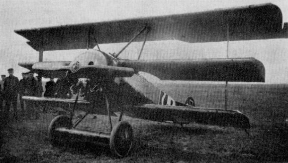
Fokker Dr I flown by Lt. Janzen of Jasta 6.

Fokker Triplanes o f Jasta 26.
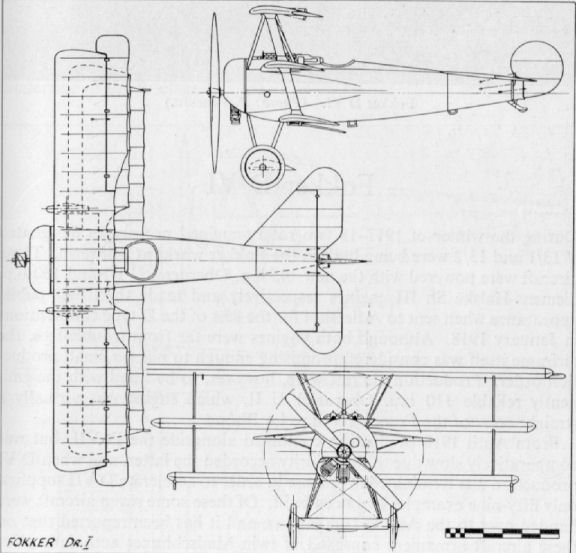
Fokker V 17
There is no record of types V 14 to V 16, and the V 17 was the first monoplane of the V series. It appeared in December 1917. Again the majority of components were from the Dr I. The cantilever wing was fabric covered and featured a single compound spar as in the Dr I wings, but its mid-wing location gave extremely poor downward-forward visibility from the cockpit. Engine was 110 h.p. Oberursel U II.
Fokker V 20
Rumoured to have been designed and constructed in 5 1/2 days during the first D types Competition, the V 20 can be said to have been little more than a hybrid between the V 17 and V 18 types. Engine was 160 h.p. Mercedes D III.
Fokker V 23
Development in the V 17, V 20 series, the V 23 differed little visibly. The wing was now of dual-spar construction and ply-covered, the ailerons were wholly inset; in fact, except for its location, the wing was much the same as that used on the later D VIII. This aircraft took part in the second D types Competition. Engine, 160 h.p. Mercedes D III. Loaded weight, 848 kg. (1,866 lb.), at which it climbed 1,000 m. (3,280 ft.) in 3 min. and to 5,000 m. (16,400 ft.) in 29.8 min.
Fokker V 25
Yet another version of the monoplane format with the wing now in the low-wing position. The wing was of twin-spar construction with ply-covering as on V 23; a vertical fin was added to the tail and a headrest aft of the cockpit. Fitted with 110 h.p. Oberursel U II engine, the machine took part in the second D types Competition. At a loaded weight of 564 kg. (1,285 lb.) it climbed 1,000 m. (3,280 ft.) in 1.7 min. and 5,000 m. (16,400 ft.) in 28.7 min.
Fokker V 6
Yet another variation of the triplane theme in the summer of 1917; with extended span and the lengthened fuselage slung above the lower wing. Power plant was 120 h.p. Mercedes D II.
Yet another variation of the triplane theme in the summer of 1917; with extended span and the lengthened fuselage slung above the lower wing. Power plant was 120 h.p. Mercedes D II.
Fokker V 8
As may be seen this aircraft, built expressly on Fokker's instructions, utilised mostly V 6 components. It was not a success, and after only two short test hops it was scrapped. Engine was 120 h.p. Mercedes D II.
As may be seen this aircraft, built expressly on Fokker's instructions, utilised mostly V 6 components. It was not a success, and after only two short test hops it was scrapped. Engine was 120 h.p. Mercedes D II.
Fokker V 38
The V 38 was the prototype Fokker C I, design of which was completed during the summer of 1918 and construction was well under way when hostilities ceased. Much of the D VII was to be seen in the V 38, although it was necessarily a larger aeroplane. Some seventy of these aircraft, inter alia, were crated up by Fokker and taken back to Holland after the war. Engine was 185 h.p. B.M.W. IIIa.
The V 38 was the prototype Fokker C I, design of which was completed during the summer of 1918 and construction was well under way when hostilities ceased. Much of the D VII was to be seen in the V 38, although it was necessarily a larger aeroplane. Some seventy of these aircraft, inter alia, were crated up by Fokker and taken back to Holland after the war. Engine was 185 h.p. B.M.W. IIIa.
Fokker V 26
Also taking part in the second D types Competition, the V 26 was a continuation of the V 17-V 25 monoplane lineage, and with the wing now in the parasol position it was the most successful. It eventually went into production as the E V, later redesignated D VIII. Engine, 110 h.p. Oberursel U II. Span, 8.34 m. (27 ft. 4 3/8 in.). Length, 5.86 m . (19 ft. 2 3/4 in.). Area, 10.7 sq.m. (115.56 sq.ft.). Weights: Empty, 405 kg. (891 lb.). Loaded, 605 kg. (1,241 lb.). Speed, 204 km.hr. (127.5 m.p.h.). Climb, 1,000 m. (3,280 ft.) in 2 min. Duration, 1 1/2 hr. Armament, twin Spandau machine-guns.
Fokker V 28
Yet another E V - D VIII prototype, the V 28, was flown at the second D types Competition with 145 h.p. Oberursel U III and 160 h.p. Goebel Goe III installations. Both engines were eleven-cylinder rotaries and of larger than standard diameter, which necessitated the bulging of the cowling. The above machine is fitted with the Oberursel motor. For the third D types Competition, held only a few weeks before the Armistice, the V 28 was again re-engined, with the Siemens-Halske Sh III. The 145 h.p. Oberursel airframe flew at 605.8 kg. (1,333 lb.) and climbed 6,000 m. (19,680 ft.) in 18.5 min. with the 140 Goebel installation flying weight was 635 kg. (1,397 lb.) and climb to 6,000 m. (19,680 ft.) took 23.5 min. Armament, twin Spandau machine-guns.
Fokker D VIII
After the success of the competition for single-seat fighters held at Johannisthal early in 1918 (in which the types were restricted to the use of the 160 h.p. Mercedes D III engine) the German High Command decided to hold another, and manufacturers were duly circularised to the effect that another competition would be held in April in which there would be no restriction on the size of either aeroplane or engine.
Fokker had on hand Reinhold Platz' prototype parasol monoplane, the V 26 powered by a 110 h.p. Oberursel engine which, after modification, was thought to stand a good chance. Main alterations were the introduction of taper into the trailing edge of the wing with the ailerons inset; the original comma rudder was enlarged and a triangular fin added. Most manufacturers entered prototypes for the competition: Albatros, Kondor, L.V.G., Pfalz, Roland, Siemens-Schuckert, etc., which were flown and assessed by both official test pilots and by pilots from the Front Line Jastas. On their appraisal the final choice rested. Eventually the Fokker cantilever parasol was selected, as it combined a rapid take-off and climb with speedy diving ability, as well as considerable agility in combat manoeuvres.
The aircraft was put into production immediately, and the first half dozen or so were rushed to the Front for operational assessment in August 1918. Jasta 6 was fully equipped with the type by 5th August, but an acute shortage of castor oil led to lubrication difficulties and many forced landings. The new aircraft were withdrawn from operations on 21st August. Three of these E Vs (as the aircraft was first designated) also crashed due to wing failure, and the type was grounded pending investigation. Two theories for the wing failure have been recorded. The first maintained that the rear spar had been strengthened on official instructions and that in this form the wing did not flex sufficiently to allow an even distribution of load, and consequently fractured. The second theory was that after the spars had been assembled and glued the top and bottom surfaces were planed down to clean them up, resulting in a weakened structure. Whichever theory is true, the fact remains that the fault was rectified and production resumed. Completed aircraft were brought up to specification and the designation was altered to D VIII, but by this time the war was in its final stages and there was no chance for this neat parasol monoplane to prove itself in combat. Jasta 6 of the Richthofen Geschwader had a few D VIIIs on its strength, and these were decorated with a black-and-white "petal" device on the cowling and black-and-white striped tailplanes. The Marine Jagdgeschwader also received some D VIIIs, and Lt. Theo Osterkamp secured his 25th and 26th victories while flying a machine of this type.
In construction the D VIII still adhered to the Fokker composite formula of wooden wings and steel-tube fuselage, the latter being closely akin to that of the Triplane. It was a welded steel-tube box-girder in which the gauge of the tubes was progressively reduced from 22 mm. diameter at the nose to 18 mm. at the tail. The bays were braced as formerly, with stranded cables looped through quadrants welded into the corners and tightened with a single turnbuckle. The welded steel-tube tail surfaces also closely resembled those of the Triplane, except for the addition of the triangular fin. The tailplane was braced from the underside to the bottom longerons by two steel-tube struts. Fabric covered the complete fuselage and empennage. The neat circular cowling - which again bore a striking degree of resemblance to the Triplane - enclosed the 110 h.p. Oberursel, copied from the French Le Rhone engine.
The cantilever wing, of pleasing proportions, had a parallel centre-section with angular cut-out, then tapered gradually to the rounded tips, which were strongly made from six fine laminations of ash. Ailerons were inset and unbalanced. The two hollow box-spars, which tapered towards the tips in both plan and elevation, were glued together and bound with fabric. Ribs were of three-ply with spruce flanges, and the whole of the internal structure was given a coat of varnish before being completely covered with three-ply sheet 1 1/2 mm. in thickness, fastened with 1/2-in. wire nails. This was again covered with fabric, resulting in a near stressed-skin surface: it also resulted in the disappearance of the scalloped trailing-edge profile which had characterised all Fokker aircraft up to this date.
A tripod arrangement of streamlined steel-tube struts supported the parasol wing; the same material was utilised for the undercarriage chassis. The now familiar aerofoil lifting surface again enclosed the axle, spreader bars and shock-absorbing cords, and an internally sprung, steel-shod tailskid of ash completed the landing gear.
Further development of the D VIII resulted in the basic airframe being fitted with 140 h.p. Oberursel (11 cylinders), 160 h.p. Goebel and 160 h.p. Siemens-Halske engines, but these remained no more than prototypes.
Handling qualities of the D VIII were reported to be pleasant except for a tendency to turn to starboard when taxi-ing. In flight it was slightly tail heavy but so light on the sensitive controls that it was not tiresome to fly.
From the cockpit visibility was first class, both upward and downward directions being almost completely unrestricted. Some criticism was leveled at the throttle (petrol) control being on the port side of the cockpit and the air adjustment control on the left side of the control column when it would have been much more convenient for them to have been located together.
TECHNICAL DATA
Description: Single-seat fighting scout.
Manufacturers: Fokker Flugzeug-Werke G.m.b.H. (Fok.).
Power Plant: One 110 h.p. Oberursel U II 9 cylinder rotary.
Dimensions: Span, 8.34 m. (27 ft. 4 3/8 in.). Length, 5.86 m. (19 ft. 2 3/4 in.). Height, 2.6 m. (8 ft. 6 3/8 in.). Area, 10.7 sq.m. (115.5 sq.ft.).
Weights: Empty, 405 kg. (893 lb.). Loaded, 605 kg. (1,334 lb.).
Performance: Maximum speed ground level, 204 km.hr. (127.5 m.p.h.) Climb, 1,000 m. (3,280 ft.) in 2 min.; 4,000 m. (13,120 ft.) in 10.75 min. Ceiling, ca. 6,000 m. (19,680 ft.). Duration, ca. l 1/2 hr.
Armament: Twin fixed Spandau machine-guns synchronised to fire forward through airscrew.
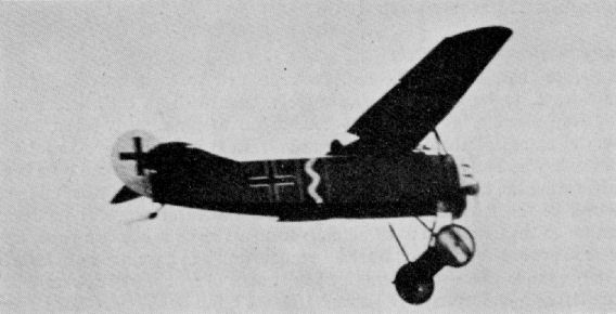
Fokker D VIII in the markings of Jasta 6.
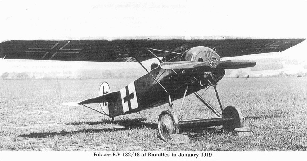
Fokker D VIII (serial 132/18).
Nine Fokker E.V fighters of Jasta 6 lined up for the camera in early August, with five D.VIIs barely visible at the far end. These photos have previously been identified as having been taken at Bernes but it seems more likely that they were taken at Chambry around 5 August.
Fokker V 27
To all intents and purposes this machine was a V 26 modified to accept the vee-eight 195 h.p. Benz IIIb engine. It participated in the second D types Competition, when, at a loaded weight of 839.6 kg. (1,847 lb.), it climbed 1,000 m. (3,280 ft.) in 3 min., 6,000 m. (19,680 ft.) in 45 min; a far from spectacular performance. It was later modified into the V 37
Fokker V 29
This aircraft was a larger version of the V 27, powered first with the 160 h.p. Mercedes D III and later with the 185 h.p. B.M.W. IIIa engine. It was a parasol version of the D VII and took part in the third D types Competition.
Fokker V 37
The V 37 was an experiment in enclosing the pilot and engine with sheet-steel armour plate with a view to using the aircraft for trench and ground-attack duties. The illustration shows the angularity of the armour plate and the gigantic spinner, which did little to improve the ungainly appearance of the aircraft. It was powered by a 195 h.p. Benz IIIb.
Fokker V 30
The V 30 was a V 26 converted into a glider with the pilot's cockpit move, to the extreme nose. One such machine was exhibited at the Paris Aero Salon in 1921.
The V 30 was a V 26 converted into a glider with the pilot's cockpit move, to the extreme nose. One such machine was exhibited at the Paris Aero Salon in 1921.
Fokker V 34
Virtually a revised B.M.W.-engined D VII, the V 34 featured the same type empennage as the V 33; the engine was also housed in a neater cowling with a more ovoid radiator. Engine, 185 h.p. B.M.W. IIIa.
Fokker V 36
With no record of V 35, the next prototype to appear was the V 36 - yet another D VII derivative. Stemming from the V 34, a return to the original D VII style fin and rudder may be noted. A second V 36 prototype was constructed, and this machine had no centre-section cut-out, and a fuel tank was installed in the axle fairing. Engine, 185 h.p. B.M.W. IIIa. Span, 8.935 m. (28 ft. 3 7/8 in.). Length, 6.46 m. (21 ft. 2 3/8 in.). Height, 3.045 m. (9 ft. 11 7/8 in.). Area, 17.6 sq.m. (190.08 sq.ft.). Weights: Empty, 637 kg. (1,401 lb.). Loaded, 871 kg. (1,916 lb.). Climb, 1,000 m. (3,280 ft.) in 1.75 min., 6,000 m. (19,680 ft.) in 18.25 min. Armament, twin fixed Spandau machine-guns.

Fokker V 36
Fok. D.VII in Dutch service, fitted with a 230-h.p. Siddeley Puma engine.
Fok. D.VII in Dutch service, fitted with a 230-h.p. Siddeley Puma engine.
Friedrichshafen FF 29
Built in small quantity from November 1914, the FF 29 and FF 29a (powered with 120 h.p. Mercedes D II engine) were used for coastal patrol and sometimes carried a small bomb load. No other armament was carried. The FF 29a had modified tail surfaces and floats.
Built in small quantity from November 1914, the FF 29 and FF 29a (powered with 120 h.p. Mercedes D II engine) were used for coastal patrol and sometimes carried a small bomb load. No other armament was carried. The FF 29a had modified tail surfaces and floats.

Friedrichshafen FF 29a
Friedrichshafen FF 31
Only two FF 31 seaplanes were built (Nos. 274 and 275), and they were delivered to the German Navy in May 1915. No. 275 is illustrated. Span, 16.85 m. (55 ft. 3 3/8 in.). Length, 10.15 m. (33 ft. 3 5/8 in.). Height, 3.9 m. (12 ft. 9 5/8 in.). Area, 60 sq.m. (648 sq.ft.). Weights: Empty, 1,040 kg. (2,288 1b.). Loaded, 1,530 kg. (3,366 lb.). Speed, 98 km.hr. (61.25 m.p.h.). Armament, one manually operated Parabellum machine-gun.
Only two FF 31 seaplanes were built (Nos. 274 and 275), and they were delivered to the German Navy in May 1915. No. 275 is illustrated. Span, 16.85 m. (55 ft. 3 3/8 in.). Length, 10.15 m. (33 ft. 3 5/8 in.). Height, 3.9 m. (12 ft. 9 5/8 in.). Area, 60 sq.m. (648 sq.ft.). Weights: Empty, 1,040 kg. (2,288 1b.). Loaded, 1,530 kg. (3,366 lb.). Speed, 98 km.hr. (61.25 m.p.h.). Armament, one manually operated Parabellum machine-gun.
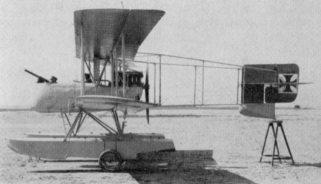
Friedrichshafen FF 31
Friedrichshafen 33 Variants
The FF 33s were undoubtedly the most multifarious of the early German patrol seaplanes. Nevertheless, their many variants could be basically divided into two categories. The 33/33b, 33e, 33j and 33s, which were mostly unarmed reconnaissance patrol seaplanes carrying a small load of bombs, were all of three-bay wing format. The 33f, 33h and 331, on the other hand, were fighters of two-bay wing layout, intended for armed patrols and on occasion for escort to reconnaissance patrol machines.
The Reconnaissance FFs. Stemming from the FF 33, all variants were of basically similar airframe construction, with differing engine, equipment installations, flotation gear and wingspan, as will be outlined later. The initial FF 33 appeared at the end of 1914 and was a quite orthodox fabric-covered wooden structure in which the pilot sat in the aft cockpit. Like the earlier FF 29, it was powered with a 120 h.p. Mercedes D II engine, and in general differed little except for modification of the float shape. The fuselage was a simple slab-sided braced box-girder structure of spruce longerons and spacers tapering to a vertical knife-edge, and with a slightly rounded top decking. A small amount of sweepback was incorporated in the wings, which were based on two main spars with wooden ribs, the trailing edges of which were linked with a wire member which imparted a scalloped effect to the profile. The ailerons, of inverse taper, were of steel-tube construction, likewise the tail assembly, and of these control surfaces only the rudder was balanced. However, only six aircraft of this type were supplied to the German Navy.
In the F F 33b, which followed, the positions of the crew were reversed, with the pilot now sitting in the forward position. In the rear cockpit the observer was equipped with a manually operated machine-gun for defence purposes. A more powerful engine, the 160 h.p. Maybach, was fitted and the radiators were sited on the fuselage sides adjacent to the front cockpit. The floats were of two-step design, with flat bottoms forward and vee section aft. As far as is known, only five of this type were built.
The next variant was the FF 33e, which was still generally similar to its predecessors but differed most noticeably in the float arrangement, the main floats being considerably lengthened and the tail float abandoned. In its place a long underfill was substituted, and this became a characteristic of practically all subsequent Friedrichshafen aircraft. This modification of the float system resulted in the most seaworthy machine to date. Another variation from the earlier machines was the installation of the 150 h.p. Benz Bz. III engine, the reliability of which was superlative for long "over water" patrols. With this engine the radiator system was again revised, the cooler now being located against the leading edge of the top wing. The FF 33e was the first of the series to be equipped with radio-telegraphy equipment, but at this stage only a transmitter was fitted. No defensive armament was installed, as development of protection escort machines was proceeding simultaneously. Some 188 FF 33es were constructed from March 1915 onwards, the final batch supplied from September 1917 to January 1918 being equipped solely as school machines and fitted with dual control.
A further refinement in the series came with the FF 33j, the most noticeable feature of which was the cleaning up of the nose-entry and the addition of a spinner to the propeller hub. A headrest for both pilot and observer was fitted, and altogether a much more pleasing appearance resulted. Both transmitting and receiving radio equipment was now installed, which made for an all-round improvement in communications. Furthermore, tools, spare parts and sea anchors were carried to facilitate repair in case of forced alighting; also full navigation equipment and signalling gear was installed.
Doubtless the most famous of all the FF seaplanes was the 33e "841" Wolfchen carried by the German auxiliary cruiser Wolf, whose depredations from November 1916 to February 1918 extended as far as the Indian and Pacific Oceans. Wolfchen was hoisted overboard on a derrick and tackle and proceeded to scout ahead of the cruiser, sending by radio to her parent ship such intelligence as became available. In all, some fifty-six flights were carried out during this period, and between each considerable maintenance was often necessary. This represented a commendable achievement on the part of all concerned, particularly as the aircraft had to be protected as much as possible against the effects of exposure and tropical climates.
Translated extracts from the Wolfchen log exemplify accomplishment:
"Pacific Ocean. 2nd June 1917. Orders. Merchant steamer which has been sighted to North of Raoul Island to be stopped and brought to Wolf."
The ship had suddenly appeared while Wolf was hove-to close to the island, engaged on engine repairs and trimming bunkers. Wolfchen started at 15.30 hours and flew north. On reaching the steamer the FF 33e descended to within 200 feet and dropped the following message in English:
"Steer south to German cruiser and do not use wireless. If not obeyed you will be bombed."
The second time the seaplane flew over the steamer it dropped a bomb only 20 yards from her bows. At once she changed course and steered for Wolf, escorted by Wolfchen. After this threat she did not use her wireless. It was the New Zealand ship Wairuna of 3,900 tons, bound for San Francisco from Auckland. The ship and her cargo were worth many hundred thousand pounds.
"Pacific Ocean. 16th June 1917. Orders. Hold up four-masted schooner sighted in the west and bring to Wolf''
Wolfchen started at 15.50 hours and flew west. It spiralled down from 500 to 250 feet. Its first two attempts to drop a message on the deck failed owing to the drift of the vessel. Both fell some distance to leeward. At the seaplane's third approach a bomb was dropped from 250 feet close by the bows. The ship at once hauled in sail and displayed the United States flag. Wolfchen ordered the vessel to steer south-east and intimated that she would be bombed if she did not follow. She at once turned in the given direction, and with Wolfchen circling overhead, was led to Wolf. It was the American schooner Winslow of 567 tons, with a cargo of coal, provisions, petrol and timber, from San Francisco. Unfortunately the petrol was useless for aircraft. Owing to bad weather, Wolfchen was again dismantled and stored away on the afternoon of 17th June 1917.
"Indian Ocean. 25th September 1917. Orders. Investigate patch of smoke which has been sighted and report on vessel, course and distance."
It proved to be the Japanese ship Hitachi Maru of 6,900 tons. The Wolfchen received a further order to support Wolf in holding up the vessel and to bomb her if she committed any hostile act. At the first shot from Wolf the ship turned to starboard intent upon escape. Thereupon a bomb was dropped about 30 yards ahead of her; about the same time the cruiser again fired, so that Wolfchen was led to believe that the ship was resisting. Wolfchen therefore flew up again and dropped another bomb from about 700 ft., which fell close by the port side. The explosion blew two men overboard and the steamer then hove to. Wolfchen then ceased bombing, but continued to circle round until the prize crew had gone on board.
The seaplane then alighted close by the vessel and discovered that the nuts on the propeller had loosened, and, in consequence of the lash on the prop-shaft, the engine could not throw true against the cranks.
The final variant of the reconnaissance FF 33 machines was the 33s, which was simply a 33j equipped with dual control for use solely as a school aircraft.
The Fighter Patrol FFs. The principal visible difference between the reconnaissance and fighter FFs was in the reduction of overall dimensions and the introduction of two-bay wing format to improve manoeuvrability. The 150 h.p. Benz engine still remained the standard power unit.
First of these two-seat fighter patrol types was the 33f, introduced in October 1915 and probably the first German naval lighting scout. Armament was a manually operated Parabellum gun for the observer. However, no more than five of these machines had been supplied when the type was superseded by the FF 33h. In this model the nose-entry was improved. Some had a radiator of aerofoil section built into the centre-section of the top wing. The ailerons and floats were also redesigned, all with a view to reducing head resistance. Modification to the float chassis included the introduction of steel-tube load struts between the floats instead of only cables as previously. Some inboard bay bracing cables were duplicated as a precaution against breakage should the gunner decide to shoot between the prop disc and the struts (as he was expected to do if necessary!) and sever one of the wires. Coming into service in January 1916, the 33hrs continued to operate until eventually some forty-five were in service.
In September 1916 the FF 33l was introduced, and production finally totalled some 135 aircraft. The fuselage length and wingspan were still further reduced, a spinner was fitted to the propeller and, finally, the aircraft achieved a reasonably happy compromise between performance and manoeuvrability - a prerequisite that plagues the design of all naval aeroplanes. For a somewhat cumbersome machine the 33l possessed marked agility, and this enabled the pilot to make use of the fixed forward gun which was now added to the armament. Its degree of seaworthiness was reasonably good, and take-off and landing from open sea in winds up to force 3 could be accomplished. On some machines the forward gun was deleted and a radio transmitter carried in its stead. By and large, the FF 33ls were able to afford a good degree of protection for their unarmed reconnaissance brethren on long patrols over the North Sea.
TECHNICAL DATA
Description:
Two-seat reconnaissance patrol twin float seaplane (33e).
Two-seat fighter patrol escort twin float seaplane (331).
Manufacturers: Flugzeugbau Friedrichshafen G.m.b.H. Manzell and Warnemunde.
Power Plant: One 150 h.p. Benz Bz III 6 cylinder in-line water-cooled engine.
Dimensions: Span, 16.75 m. (54 ft. 11 1/2 in.), 33e; 13.3 m. (43 ft. 7 5/8 in.), 33l. Length, 10.45 m. (34 ft. 3 1/2 in.), 33e; 8.825 m. (28 ft. 11 1/2 in.), 33l. Height, 3.725 m. (12 ft. 2 5/8 in.), 33c; 3.95 m. (12 ft. 10 1/2 in.), 33l. Wing area, 52.7 sq.m. (569.2 sq.ft.), 33c; 40.54 sq.m. (437.8 sq.ft.), 33l.
Weights: Empty, 1,008 kg. (2,217.6 lb.), 33e; 916 kg. (2,021.8 lb.), 33l. Loaded, 1,635 kg. (3,636.6 lb.), 33e; 1,373 kg. (3,020.6 lb.), 33l.
Performance: Maximum speed, 119 km.hr. (74.5 m.p.h.), 33e; 136 km.hr. (85 m.p.h.), 33l. Initial climb, 1,000 m. (3,280 ft.) in 17.5 min., 33e; in 8 min., 33l. Duration, approximately 5-6 hr., both types.
Armament:
33e - None. (Some aircraft fitted with rear gun.)
33l - One fixed Spandau machine-gun forward and one manually operated Parabellum machine-gun in rear cockpit.
N.B. Data is general. Nearly all production machines had detail differences rom batch to batch.
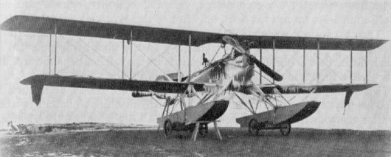
Friedrichshafen FF 33e.
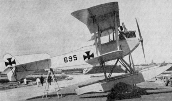
Friedrichshafen FF 33h (Marine number 695).
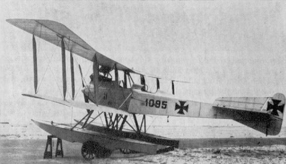
Friedrichshafen FF 33j (Marine number 1095).
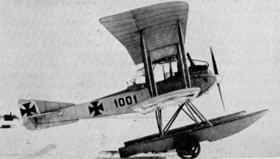
Friedrichshafen FF 33l (Marine number 1001).
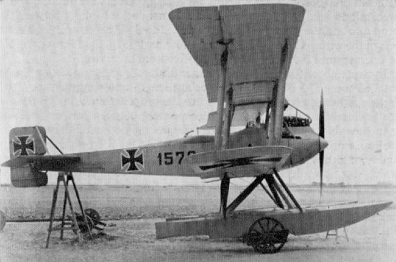
Friedrichshafen FF 33l (Marine number 1578, with modified tail).
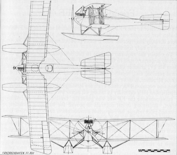
Friedrichshafen FF 33E
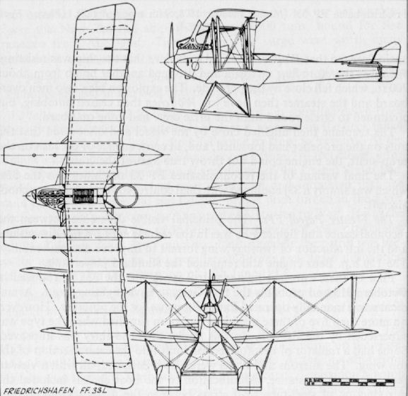
Friedrichshafen FF 33L
Friedrichshafen FF 34
Another Friedrichshafen to pusher format was the FF 34, powered with 240 h.p. Maybach Mb IV engine; only a single example was built. It was subsequently rebuilt with a normal fuselage to become FF 44, but retained the same naval number "117". Span, 18.4 m. (60 ft. 4 1/2 in.). Length, 10.85 m. (35 ft. 7 1/8 in.). Height, 4.1 m. (13 ft. 5 1/2 in.). Armament, one manually operated Parabellum machine-gun. A radio transmitter was carried.
Another Friedrichshafen to pusher format was the FF 34, powered with 240 h.p. Maybach Mb IV engine; only a single example was built. It was subsequently rebuilt with a normal fuselage to become FF 44, but retained the same naval number "117". Span, 18.4 m. (60 ft. 4 1/2 in.). Length, 10.85 m. (35 ft. 7 1/8 in.). Height, 4.1 m. (13 ft. 5 1/2 in.). Armament, one manually operated Parabellum machine-gun. A radio transmitter was carried.
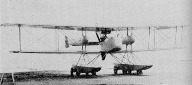
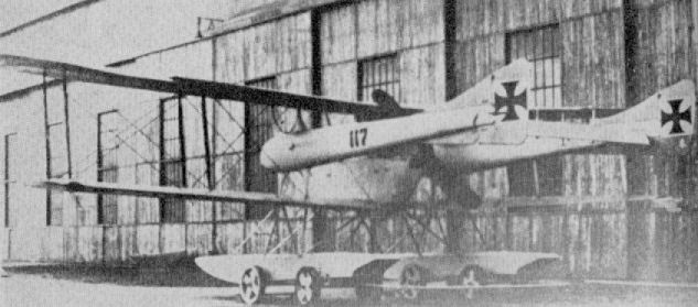
Friedrichshafen FF 34
Friedrichshafen FF 35
Built in February 1915, the FF 35 was intended as a torpedo carrier, but only a single machine (No. 300) was constructed. The twin 160 h.p. Mercedes D III engines drove pusher airscrews. Span, 23.74 m. (77 ft. 10 3/4 in.). Length, 13.5 m. (44 ft. 3 5/8 in.). Area, 100 sq.m. (1,080 sq.ft.). Weights: Empty, 2,292 kg. (5,042 lb.). Loaded, 3,543 kg. (7,795 lb.). Speed, 114 km.hr. (71.25 m.p.h.). Armament, torpedo and one or two manually operated Parabellum machine-guns.
Built in February 1915, the FF 35 was intended as a torpedo carrier, but only a single machine (No. 300) was constructed. The twin 160 h.p. Mercedes D III engines drove pusher airscrews. Span, 23.74 m. (77 ft. 10 3/4 in.). Length, 13.5 m. (44 ft. 3 5/8 in.). Area, 100 sq.m. (1,080 sq.ft.). Weights: Empty, 2,292 kg. (5,042 lb.). Loaded, 3,543 kg. (7,795 lb.). Speed, 114 km.hr. (71.25 m.p.h.). Armament, torpedo and one or two manually operated Parabellum machine-guns.
Friedrichshafen G I
First of the twin-engined bombers built by Friedrichshafen in 1915, the three-bay G I paved the way for the G III, from which it differed mainly in having a biplane tail. A crew of three was carried. Power was twin 150 h.p. Benz Bz III engines driving pusher airscrews. A manually operated Parabellum machine-gun was carried in the nose cockpit.
Friedrichshafen G II
Built during 1916, the G II was a neat twin-engined design for its period and, unusually, had only two-bay outer wing panels. It was a reasonably successful aircraft and passed into limited production. The attachments behind the wheels were to prevent stones and mud being flung into the neatly spinnered, pusher airscrews. Engines, two 200 h.p. Benz Bz IV. Span, 20.3 m. (66 ft. 7 3/8 in.). Length, 11.05 m. (36 ft. 3 in.). Height, 3.6 m. (11 ft. 9 3/4 in.). Area, 70 sq.m. (756 sq.ft.). Weights: Empty, 2,200 kg. (4,840 lb.). Loaded, 3,152 kg. (6,934.4 lb.). Armament, one manually operated Parabellum machine-gun in nose cockpit and another aft of the wings.
Friedrichshafen G III
In company with the Gotha G V, the Friedrichshafen G III twin-engined bomber formed the backbone of the German Bombengeschwader force on the Western Front from early 1917 until November 1918. For the most part these aircraft were used for long-distance night raids, and on several occasions were used in raids on Paris. They were probably used, together with Gothas, in raids upon Great Britain, but certain confirmation is not to hand. Although very similar in size and layout to their Gotha brethren, the Friedrichshafens could be distinguished by their raked wingtips with aileron horn balances inset. They also had distinctive tail surfaces, the chord of which was greater than the span. The G III was a larger and more powerful three-bay version of the earlier two-bay G II, which was produced on a small scale. On 16th February 1918 a G III was brought down reasonably intact by A.A. fire and became the subject of a detailed Allied report.
Full crew complement of the Friedrichshafen G III was three: pilot, gunner and a bombing officer, who also "doubled" as gunner when necessary. In practice, the number of the crew often varied, and G IIIs were sometimes operated by only two crew members, this being facilitated by the intercommunication of the cockpits enabling places to be changed during flight.
Structurally, the G III consisted of a complete central section which comprised the cockpit and "cabin" portion (where fuel tanks and some bombs were carried), the engines and the centre-section of the upper and lower wings. To this central section the mainplanes and forward and rear parts of the fuselage were bolted. The section itself was some 4 ft. by 4 ft. 3 in. in cross-section, with stout longerons and ply bulkheads, and was completely ply covered. The forward bulkhead served as an instrument board, and immediately aft of it were positioned side-by-side seats. The pilot's seat was fixed and upholstered, but that for the bombing officer was a folding steel-tube affair with webbing back-rest. Aft of the cockpit the section was "roofed" over with plywood, part of which was detachable to give access to the second main fuel tank, the first being under the seats. At each side of the passageway were racks for stowing five 10 kg. bombs each. The main bomb racks were fitted externally below the nacelle and were of tubular frames. These were readily removable, as the bomb loads were varied to suit the tactical or strategical requirements.
The forward part of the fuselage, containing the front cockpit with the bomb-release gear, was plywood covered and bolted to the main section. The aft section extended from a point level with the airscrews and was of square-section longerons and spacers with bays transversely cable braced and, except for the extreme rear end (which was ply covered to absorb tail stresses), was fabric covered. The rear cockpit was provided with a movable gun mounting, and in the raised floor was a trap door in which were fitted two celluloid windows to facilitate downward vision. A novel feature in the otherwise orthodox controls was a trimming device in the form of a winch connected to tension springs 1 m. in length introduced in the elevator linkage. Winding to the left gave tail-heavy trim; turns to the right gave the reverse trim.
The centre-section portion of the wings was built up on 2-in.-diameter steel-tube spars braced diagonally to form an X. All main ribs were of three-ply with spruce flanges, and had false ribs interspaced on the top wing only. The upper surface of the lower centre-section was plywood surfaced, the remainder fabric. Two 260 h.p. Mercedes D IV engines with pusher airscrews and frontal car-type radiators were slung between the wings. The actual bearer struts and the connecting struts to the upper wing were of streamlined steel tube of 1/16 in. wall thickness. In front elevation these struts formed a vee, the lower end of which was attached to the tubular steel spars on the bottom wing; the upper ends were pin-jointed to the top-wing main spars, the pin being utilised to anchor the bracing cables.
Two fabric-wrapped built-up box-spars of spruce formed the basis of the outer, detachable portions of the wings and were braced with stranded cables and steel-tube compression members. The three-ply main ribs were socketed into grooved spruce flanges, and between each ran a false rib extending as far aft as the rear spar. A solid spar of near semicircular shape formed the leading-edge, while the usual wire comprised the trailing-edge member. Inboard the trailing edge was cut back to allow airscrew clearance. With the exception of the inner ends of the lower wings, which were ply-covered on the top surfaces, the remainder of the outer panels were fabric covered. The interplane struts, of somewhat massive proportions, were actually built up with a central spine of ash, and the streamlining fore and aft portions of low-quality timber.
Complete tail surfaces and ailerons were mainly of steel-tube construction, only a few wooden stringers being used in the tailplane. All the control surfaces were generously horn balanced, the rudder and aileron dances being inset, the elevators overhung. Streamlined steel tubes traced the tailplanes to the fuselage, and to these sharp steel points were welded to deter their use when manhandling the aircraft on the ground. As is apparent, the five-wheel undercarriage was a somewhat cumbersome appendage, the centre wheel being solely to prevent nosing over on landing. The main wheels were sprung with steel-spring shock absorbers ad fitted with guards to prevent stones being flung into the airscrew. The tailskid was a sturdy ash component, heavily steel shod and sprung within the fuselage.
A modified version with a compound tail assembly was also produced later; known as the G IIIa, this version was built under licence by the Daimler Works and Hanseatische Flugzcug-Werke.
TECHNICAL DATA
Description: Twin-engined long-range bomber.
Manufacturers: Flugzeubau Friedrichshafen G.m.b.H. Manzell. (Fdh.).
Sub-contractors: Hanseatische Flugzeug-Werke (93 G III and G IIIa) (Hansa.); Daimler Motoren-Gesellschaft (245 G III and G IIIa) (Daim.).
Power Plant: Two 260 h.p. Mercedes D IVa 6 cylinder in-line water-cooled engines.
Dimensions: Span, 237 m. (77 ft. 9 1/4 in.). Length, 12.8 m. (42 ft.). Area, 95 sq.m. (1,020 sq.ft.).
Weights: Empty, 2,695 kg. (5,929 lb.). Loaded, 3,930 kg. (8,646 lb.).
Performance: Maximum speed, 135 km.hr. (84.35 m.p.h.). Duration, 5 hr.
Armament: Two or three manually operated Parabellum machine-guns in nose and rear cockpits. Bomb load varied to suit tactical, or strategical, requirements, but averaged 1,500 kg. (3,300 lb.)
Friedrichshafen G IIIa
Virtually a standard G III, the G IIIa differed only in having a compound tail and less curved wingtips. The majority were built under licence by Daimler Motoren-Werke. Engines, two 260 h.p. Mercedes D IVa. For all details see G III in main text.
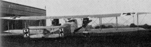
Friedrichshafen G I
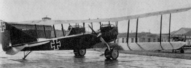
Friedrichshafen G II
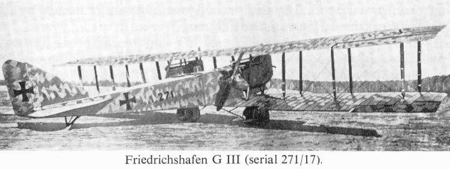
Friedrichshafen G III (serial 271/17)
Friedrichshafen C I
This C I product of the Friedrichshafen factory was no more than a FF 33 L seaplane (No. 1267) fitted with a conventional land undercarriage chassis. Only the single example was built. Engine, 150 h.p. Benz III. Span, 13.3 m. (43 ft. 7 3/4 in.). Length, 8.0 m. (26 ft. 3 in.). Armament, one Parabellum machine-gun in rear cockpit.
This C I product of the Friedrichshafen factory was no more than a FF 33 L seaplane (No. 1267) fitted with a conventional land undercarriage chassis. Only the single example was built. Engine, 150 h.p. Benz III. Span, 13.3 m. (43 ft. 7 3/4 in.). Length, 8.0 m. (26 ft. 3 in.). Armament, one Parabellum machine-gun in rear cockpit.
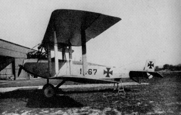
Friedrichshafen C I
Friedrichshafen D I
This clean little single-seat fighter was built during 1916, but as it offered no improvement over the Albatros lighters, which had obviously influenced its design, it did not go into production. Engine, 160 h.p. Mercedes D III. Armament, twin Spandau machine-guns forward.
This clean little single-seat fighter was built during 1916, but as it offered no improvement over the Albatros lighters, which had obviously influenced its design, it did not go into production. Engine, 160 h.p. Mercedes D III. Armament, twin Spandau machine-guns forward.
Friedrichshafen FF 37
Although no details are available, this aircraft was undoubtedly simply a land version of the FF 31 "pusher" seaplane. Engine, 150 h.p. Benz Bz III.
Although no details are available, this aircraft was undoubtedly simply a land version of the FF 31 "pusher" seaplane. Engine, 150 h.p. Benz Bz III.

A fine shot of the rarely pictured two seat, pusher-engined Friedrichshafen FF37, or C I to give it its military designation. Of early 1916 vintage, the experimental FF37's general layout appears to have been influenced by that of the Royal Aircraft Factory's F.E.2, following the British practice of seating the gunner in the nose, forward of the pilot. The FF37 was destined never to progress beyond the prototype stage.
Friedrichshafen FF 39
Some fourteen machines of FF 39 type, which was virtually a refined FF 33e, were supplied from December 1915 onwards. It was used for reconnaissance patrol duties and carried a radio transmitter. Engine, 200 h.p. Benz Bz IV. Span, 17.1 m. (56 ft. 1 3/8 in.). Length. 11.6 m. (38 ft. 0 3/4 in.). Height, 4.3 m. (14 ft. 1 3/8 in.). Area. 68.4 sq.m. (739 sq.ft.) Weights: Empty, 1,438 kg. (3,164 lb.). Loaded. 2.102 kg. (4.624lb.). Speed 137km.hr. (85.625 m.p.h.). Climb, 1,000 m. (3,280 ft.) in 9 min. Duration 5 hr. Armament, one manually operated Parabellum machine-gun in rear cockpit.
Some fourteen machines of FF 39 type, which was virtually a refined FF 33e, were supplied from December 1915 onwards. It was used for reconnaissance patrol duties and carried a radio transmitter. Engine, 200 h.p. Benz Bz IV. Span, 17.1 m. (56 ft. 1 3/8 in.). Length. 11.6 m. (38 ft. 0 3/4 in.). Height, 4.3 m. (14 ft. 1 3/8 in.). Area. 68.4 sq.m. (739 sq.ft.) Weights: Empty, 1,438 kg. (3,164 lb.). Loaded. 2.102 kg. (4.624lb.). Speed 137km.hr. (85.625 m.p.h.). Climb, 1,000 m. (3,280 ft.) in 9 min. Duration 5 hr. Armament, one manually operated Parabellum machine-gun in rear cockpit.
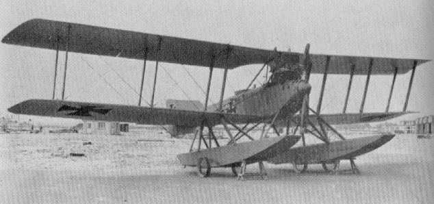
Friedrichshafen FF 39
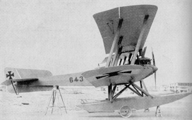
Fdh FF39C (1915/16).
Friedrichshafen FF 40
Carrying a crew of three, the FF 40 was a patrol seaplane powered with a single 240 h.p. Maybach engine mounted in the fuselage and driving twin tractor airscrews between the wings. Only a single aircraft (No. 669) was built and supplied to the German Navy during March 1916. Span, 21.0 m. (68 ft. 10 7/8 in.). Length, 12.43 m. (40 ft. 9 1/2 in.). Height, 4.4 m. (14 ft. 5 1/4 in.). Area, 88.9 sq.m. (960 sq.ft.). Weights: Empty, 1,829 kg. (4,024 lb.). Loaded, 2,539 kg. (5,586 lb.). Armament, one manually operated Parabellum machine-gun in nose.
Carrying a crew of three, the FF 40 was a patrol seaplane powered with a single 240 h.p. Maybach engine mounted in the fuselage and driving twin tractor airscrews between the wings. Only a single aircraft (No. 669) was built and supplied to the German Navy during March 1916. Span, 21.0 m. (68 ft. 10 7/8 in.). Length, 12.43 m. (40 ft. 9 1/2 in.). Height, 4.4 m. (14 ft. 5 1/4 in.). Area, 88.9 sq.m. (960 sq.ft.). Weights: Empty, 1,829 kg. (4,024 lb.). Loaded, 2,539 kg. (5,586 lb.). Armament, one manually operated Parabellum machine-gun in nose.
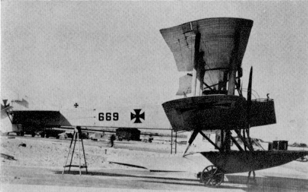
Friedrichshafen FF 40
Friedrichshafen FF 41 (compound tail)
Nine examples of FF 41 were built; in both single and compound tail versions, and supplied from February 1916 onwards. Intended for torpedo-carrying duties; a crew of three was carried. The twin 150 h.p. Benz Bz III engines were encased in neat metal housings and drove tractor airscrews. Span, 21.96 m. (72 ft. 0 3/4 in.). Length, 13.27 m. (43 ft. 6 1/2 in.). Height, 4.7 m. (15 ft. 5 1/8 in.). Area, 112.5 sq.m. (1,215 sq.ft.). Weights: Empty, 2,300 kg. (5,060 lb.). Loaded, 3,670 kg. (8,074 lb.). Speed, 125 km.hr. (78.125 m.p.h.). Range, 575 km. (360 miles). Armament, torpedo and manually operated machine-gun in front cockpit.
Nine examples of FF 41 were built; in both single and compound tail versions, and supplied from February 1916 onwards. Intended for torpedo-carrying duties; a crew of three was carried. The twin 150 h.p. Benz Bz III engines were encased in neat metal housings and drove tractor airscrews. Span, 21.96 m. (72 ft. 0 3/4 in.). Length, 13.27 m. (43 ft. 6 1/2 in.). Height, 4.7 m. (15 ft. 5 1/8 in.). Area, 112.5 sq.m. (1,215 sq.ft.). Weights: Empty, 2,300 kg. (5,060 lb.). Loaded, 3,670 kg. (8,074 lb.). Speed, 125 km.hr. (78.125 m.p.h.). Range, 575 km. (360 miles). Armament, torpedo and manually operated machine-gun in front cockpit.
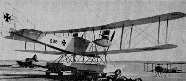
Friedrichshafen FF 41 (single tail)
Friedrichshafen FF 43
This neat little single-seater was designed for seaplane station defence duties, but only a single machine (No. 749) was built. It was delivered in June 1916. Engine, 160 h.p. Mercedes D III. Span, 9.92 m. (32 ft. 6 5/8 in.). Length, 8.5 m. (27 ft. 10 3/4 in.). Height, 3.39 m. (11 ft. 1 1/2 in.). Area, 31 sq.m. (335 sq.ft.). Weights: Empty, 798 kg. (1,756 lb.). Loaded, 1,078 kg. (2,372 lb.). Speed, 163 km.hr. (101.875 m.p.h.). Climb, 1,000 m. (3,280 ft.) in 6 min., 2,000 m. (6,560 ft.) in 12 min. Armament, two Spandau machine-guns forward.
This neat little single-seater was designed for seaplane station defence duties, but only a single machine (No. 749) was built. It was delivered in June 1916. Engine, 160 h.p. Mercedes D III. Span, 9.92 m. (32 ft. 6 5/8 in.). Length, 8.5 m. (27 ft. 10 3/4 in.). Height, 3.39 m. (11 ft. 1 1/2 in.). Area, 31 sq.m. (335 sq.ft.). Weights: Empty, 798 kg. (1,756 lb.). Loaded, 1,078 kg. (2,372 lb.). Speed, 163 km.hr. (101.875 m.p.h.). Climb, 1,000 m. (3,280 ft.) in 6 min., 2,000 m. (6,560 ft.) in 12 min. Armament, two Spandau machine-guns forward.
Friedrichshafen FF 44
This was the FF 34 aircraft (No. 117) rebuilt with a normal fuselage which bore the same naval number. It was a two-seat patrol seaplane in which a 240 h.p. Maybach Mb IV engine, fitted with reduction gears, was installed. Span, 18.4 m. (60 ft. 4 1/2 in.). Length, 10.85 m. (35 ft. 7 1/8 in.). Height, 4.25 m. (13 ft. 11 3/8 in.). Area, 68.5 sq.m. (740 sq.ft.). Weights: Empty, 1,562 kg. (3,436 lb.). Loaded, 2,305 kg. (5,071 lb.). Climb, 1,000 m. (3,280 ft.) in 8.8 min., 2,000 m. (6,560 ft.) in 22.1 min. Duration, 5 hr. Armament, one manually operated Parabellum machine-gun in rear cockpit.
This was the FF 34 aircraft (No. 117) rebuilt with a normal fuselage which bore the same naval number. It was a two-seat patrol seaplane in which a 240 h.p. Maybach Mb IV engine, fitted with reduction gears, was installed. Span, 18.4 m. (60 ft. 4 1/2 in.). Length, 10.85 m. (35 ft. 7 1/8 in.). Height, 4.25 m. (13 ft. 11 3/8 in.). Area, 68.5 sq.m. (740 sq.ft.). Weights: Empty, 1,562 kg. (3,436 lb.). Loaded, 2,305 kg. (5,071 lb.). Climb, 1,000 m. (3,280 ft.) in 8.8 min., 2,000 m. (6,560 ft.) in 22.1 min. Duration, 5 hr. Armament, one manually operated Parabellum machine-gun in rear cockpit.
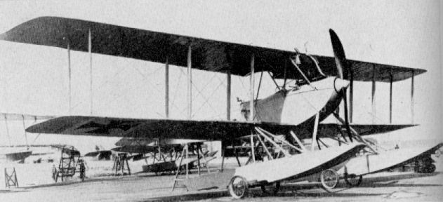
Friedrichshafen FF 44
Friedrichshafen FF 48
Designed to undertake a more offensive role, the FF 48 was classed as a two-seat fighter seaplane (Seekampf), both pilot and observer being equipped with machine-guns. A direct-drive 240 h.p. Maybach engine gave a good turn of speed to a relatively large machine. Only three machines (Nos. 1472-1474) were built and supplied from April 1917 on. Span, 16.25 m. (53 ft. 3 7/8 in.). Length, 11.2 m. (36 ft. 9 in.). Height, 4.4 m. (14 ft. 5 1/4 in.). Area, 68 sq.m. (734 sq.ft.). Weights: Empty, 1,591 kg. (3,500 lb.). Loaded, 2,216 kg. (4,885 lb.). Speed. 153 km.hr. (95.56 m.p.h.). Climb, 1,000 m. (3.280 ft.) in 6.4 min. Duration, 5 3/4 hr. Armament, one fixed Spandau forward and one manually operated Parabellum machine-gun in rear cockpit.
Designed to undertake a more offensive role, the FF 48 was classed as a two-seat fighter seaplane (Seekampf), both pilot and observer being equipped with machine-guns. A direct-drive 240 h.p. Maybach engine gave a good turn of speed to a relatively large machine. Only three machines (Nos. 1472-1474) were built and supplied from April 1917 on. Span, 16.25 m. (53 ft. 3 7/8 in.). Length, 11.2 m. (36 ft. 9 in.). Height, 4.4 m. (14 ft. 5 1/4 in.). Area, 68 sq.m. (734 sq.ft.). Weights: Empty, 1,591 kg. (3,500 lb.). Loaded, 2,216 kg. (4,885 lb.). Speed. 153 km.hr. (95.56 m.p.h.). Climb, 1,000 m. (3.280 ft.) in 6.4 min. Duration, 5 3/4 hr. Armament, one fixed Spandau forward and one manually operated Parabellum machine-gun in rear cockpit.
Friedrichshafen FF 49c
As a successor to the FF 33j reconnaissance patrol seaplane the Friedrichshafen firm brought out, in May 1917, the FF 49c, although the two types were actually interspersed with a short production batch of FF 39, which amounted to only fourteen aircraft.
To obtain the required increase in performance more power was obviously necessary, and to this end the FF 49c was fitted with the 200 h.p. Benz Bz IV, another engine of proven reliability. A satisfying improvement resulted and, together with an all-round strengthening of the airframe structure, a more rugged and reliable aeroplane resulted. On more than one occasion 49cs made open-sea landings to rescue other crews and experienced little difficulty in taking off again with the double load.
In appearance the FF 49c was generally similar to the 33j, although larger. Balancing of all controls improved the handling qualities and lessened pilot fatigue, an important consideration on long patrols. It also enabled the aircraft to give a good account of itself if attacked, as the observer was now armed with a machine-gun, which had not previously been the case with the older FF reconnaissance types. Both transmitting and receiving radio-telegraphy equipment was fitted, which enabled the crews to receive instructions during patrols as well as to transmit their observations.
A special bomber variant of this machine existed, and was known as the 49b. This was almost identical except that the pilot was moved to the aft cockpit and the observer was not equipped with a machine-gun. Only twenty-five of this variant were built.
The FF 49c itself was found to possess such a degree of efficiency that it remained in service right up to the end of the war. About 235 aircraft were built by the parent firm and various sub-contractors.
Testimony to the ruggedness of the type is to be found in the experiences of FF49c No. 1874, which, early on 10th May 1918, was swung out from the seaplane carrier Santa Helena for a reconnaissance patrol over English coastal waters. With an N.C.O. crew - Hans Sommermann (pilot) and Georg Patzoldt (observer) - the Friedrichshafen took off in company with another 49c and commenced to map a new minefield they discovered when they eventually reached their patrol zone. This they continued to do until the fuel gauges indicated time for return; Patzoldt signalled the crew of the accompanying seaplane, whereupon they turned in the direction of Germany.
By 11.00 hours, after some six hours in the air, fuel was exhausted, the parent carrier ship nowhere in sight; both aircraft alighted on the water, radioing SOS calls as they glided down. On touching down, the sea anchors were streamed to avoid drifting, as surface rescue vessels from either Borkum or Norderney were expected to reach them before dark. However, night fell with no sign of rescue, and with it came a freshening of the wind. The pangs of hunger and thirst became manifest to the crews, but there was no water other than that in the radiators, which, having been mixed with glycerine, was barely palatable. Soon after midnight a strong sea came up and No. 1874 broke away from her sea anchor and rapidly started to drift.
The drift continued, all through a stormy and overcast Sunday and again through another anxious night. Every second hour the crew of No. 1874 fired Very lights in the hope of attracting the attention of some vessel. With the break of another day came the hope that as the drift had been towards the English coast, perhaps they might be picked up by the Royal Navy, but no vessels materialised, and so their ordeal continued. The wind now backed to the south-west, and the seaplane began to drift away from British waters out into the North Sea again.
On the fifth day a list developed which they sought to correct by hacking away part of a wing panel but were too weak to wield the axe. Fog obscured the view on the sixth day, but when eventually it lifted fishing vessels were sighted, but these ignored all signals. Eventually, well after midday, Patzoldt somehow managed to tear out a piece of rib to which he fastened his handkerchief, and at last a vessel moved in to pick them up. This was the Swedish fishing smack Argo II, whose master later explained that he had interpreted the red Very lights they had fired as warnings to keep away - had white lights been fired he would have immediately come alongside, but by then they had none left.
Sommermann and Patzoldt were rescued some 27 miles from the Norwegian coast, and, exactly a week after their ordeal began, were landed at the Swedish port of Marstrand. Here they learned that their companion FF 49c had been rescued on the fourth day by a Dutch boat whose attention had been ingeniously attracted by SOS bursts from the aircraft's machine-gun.
It was finally reckoned, when Sommermann and Patzoldt returned to Germany, that the FF 49c No. 1874 had drifted almost twice across the North Sea in a period of some 140 hours.
TECHNICAL DATA
Description: Two-seat reconnaissance patrol twin-float seaplane.
Manufacturers: Flugzeugbau Friedrichshafen G.m.b.H.
Sub-contractors: Luftfahrzeug Gesellschaft m.b.H.; Sablatnig Flugzeugbau G.m.b.H.
Power Plant: One 200 h.p. Benz Bz IV 6 cylinder in-line water-cooled engine.
Dimensions: Span, 17.15 m. (56 ft. 3 1/4 in.). Length, 11.65 m. (38 ft. 2 3/4 in ). Height, 4.5 m. (14 ft. 9 1/4 in.). Wing area, 71.16 sq.m. (768.5 sq.ft.).
Weights: Empty, 1.515 kg. (3,333 lb.). Loaded, 2,147 kg. (4,723.4 lb.).
Performance: Maximum speed, 139.5 km.hr. (87.4 m.p.h.). Initial climb, 1,000 m. (3,280 ft.) in 8 min. Duration, 5 2/3 hr.
Armament: One fixed Spandau machine-gun forward and one manually operated Parabellum machine-gun in rear cockpit.
N.B. Data is general. Many machines had slight detail differences from batch to batch.
Friedrichshafen FF 49 B
This seaplane, of which twenty-live examples were built, was a 49c modified solely for bombing duties. For this role the positions of the crew were reversed, with the pilot in the rear cockpit. No armament was fitted but radio transmitting gear was carried. Engine, 200 h.p. Benz Bz IV. Span, 17.35 m. (56 ft. 11 1/8 in.). Length, 11.525 m. (37 ft. 9 3/4 in.). Height, 4.25 m. (13 ft. 11 3/8 in.). Area, 71.16 sq.m. (769 sq.ft.). Weights: Empty, 1,432 kg. (3,150 lb.). Loaded, 2,097 kg. (4,613 lb.). Speed, 152 km.hr. (95 m.p.h.). Climb, 1,000 m. (3,280 ft.) in 91 min. Duration, 5 1/2 hr. Armament, none.

Friedrichshafen FF 49 B

Friedrichshafen FF 49c with Marine number 1602.
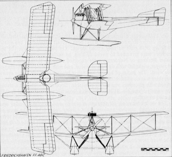
Friedrichshafen FF 53
Twin-engined torpedo aircraft. Three built: Nos. 1663-1665, June 1917. Power units 260 h.p. Mercedes C IVa.
Twin-engined torpedo aircraft. Three built: Nos. 1663-1665, June 1917. Power units 260 h.p. Mercedes C IVa.

Fdh FF53 (1918). This long-range maritime reconnaissance aircraft was developed from the FF.45/FF.61 (Fdh G.III/IV). The first flight took place on Lake Constance on July 30, 1918. A total of three aircraft were delivered.
Friedrichshafen D Type
Built during 1917, this quadruplane (vierdecker) was a purely experimental machine and by no means successful, for it crashed on its first flight. The engine was a 160 h.p. Mercedes D III, and the three-ply skinned fuselage bore unmistakable Albatros resemblance.
Built during 1917, this quadruplane (vierdecker) was a purely experimental machine and by no means successful, for it crashed on its first flight. The engine was a 160 h.p. Mercedes D III, and the three-ply skinned fuselage bore unmistakable Albatros resemblance.
Friedrichshafen N I
Built during 1917, this aircraft came into the new "N" classification for single-engined two-seaters for night bombing duties. It appeared a singularly large and cumbersome aircraft for a single-engined machine. The wings were drastically swept, which resulted in a staggering length of nose for the pilot to see over, and must have been near impossible for landing at night - when the type was intended to operate. Engine, 260 h.p. Mercedes D IVa.
Built during 1917, this aircraft came into the new "N" classification for single-engined two-seaters for night bombing duties. It appeared a singularly large and cumbersome aircraft for a single-engined machine. The wings were drastically swept, which resulted in a staggering length of nose for the pilot to see over, and must have been near impossible for landing at night - when the type was intended to operate. Engine, 260 h.p. Mercedes D IVa.
Friedrichshafen FF 59a, FF 59b
Two versions of the FF 59 with modified tail surfaces, which led eventually to the FF 59c, for details of which see following page, all general details being applicable.
Friedrichshafen FF 59c
Supplied from June 1918 onwards, the FF 59c reverted to the less powerful 200 h.p. Benz engine and was little more than a modified FF 39 fitted with both transmitting and receiving radio equipment. The inboard bracing cables were deleted, thus enabling the gunner to hazard a shot forward between the wings should the necessity arise. Span, 17.8 m. (58 ft. 4 7/8 in.). Length, 11.3 m. (37 ft. 1 in.). Height, 4.25 m. (13 ft. 11 3/8 in.). Area, 71.5 sq.m. (772 sq.ft.). Weights: Empty, 1,588 kg. (3,494 lb.). Loaded, 2,248 kg. (4,946 lb.). Speed, 142 km.hr. (88.75 m.p.h.). Climb, 1,000 m. (3,280 ft.) in 8.9 min., 3,000 m. (9,840 ft.) in 49.7 min. Duration, 5 2/3 hr. Armament, one manually operated Parabellum machine-gun in rear cockpit.
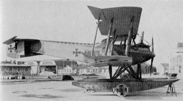
Friedrichshafen FF 59a

Friedrichshafen FF 59c
Friedrichshafen FF 60
Powered with, four 160 h.p. Mercedes D III engines, the FF 60 was a giant experimental triplane, built during 1918, and carried a crew of four. Intended for long-range patrol duties, a defensive armament of three to four Parabellum machine-guns was carried.
Powered with, four 160 h.p. Mercedes D III engines, the FF 60 was a giant experimental triplane, built during 1918, and carried a crew of four. Intended for long-range patrol duties, a defensive armament of three to four Parabellum machine-guns was carried.

Friedrichshafen FF 60
Friedrichshafen FF 63
The only information to be found on this aircraft is that it was a copy of the Brandenburg W 29, although it would appear more true to say that the design was based on the Brandenburg, as it was far from an exact copy.
The only information to be found on this aircraft is that it was a copy of the Brandenburg W 29, although it would appear more true to say that the design was based on the Brandenburg, as it was far from an exact copy.
Friedrichshafen FF 64
Development of the FF 64 was due to the success of the ship-borne Wolfchen. It was especially designed for easy launching, and the wings were arranged to fold for compact shipboard stowage without its structural strength and seaworthiness being affected. Radio transmitter and receiver were installed. Only three aircraft were built and supplied from March 1918. Power unit was 160 h.p. Mercedes D III, and a manually operated Parabellum machine-gun was carried in rear cockpit.
Development of the FF 64 was due to the success of the ship-borne Wolfchen. It was especially designed for easy launching, and the wings were arranged to fold for compact shipboard stowage without its structural strength and seaworthiness being affected. Radio transmitter and receiver were installed. Only three aircraft were built and supplied from March 1918. Power unit was 160 h.p. Mercedes D III, and a manually operated Parabellum machine-gun was carried in rear cockpit.
Friedrichshafen FF 62
No details available of this twin-engined bomber, but probably similar to the G IV, and may possibly have been designated G V
No details available of this twin-engined bomber, but probably similar to the G IV, and may possibly have been designated G V
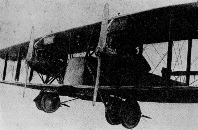
Friedrichshafen FF 62
Geest Single-seat Fighter
Built by Aviatik firm, to designs of Dr. Geest, during the winter of 1916-17. Something of the pre-war Mowe wing profile was perpetuated. Engine, 160 h.p. Mercedes D III. Speed, 160 km.hr. (100 m.p.h.). Climb, 3,500 m. (11,480 ft.) in 17 1/2 min. Armament, probably twin fixed Spandau machine-guns.
Built by Aviatik firm, to designs of Dr. Geest, during the winter of 1916-17. Something of the pre-war Mowe wing profile was perpetuated. Engine, 160 h.p. Mercedes D III. Speed, 160 km.hr. (100 m.p.h.). Climb, 3,500 m. (11,480 ft.) in 17 1/2 min. Armament, probably twin fixed Spandau machine-guns.
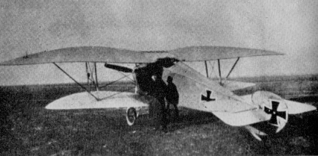
Geest Single-seat Fighter
Germania B 1915
Orthodox wood and fabric aircraft with ply-skinned fuselage. Several aircraft were built and used by the firm's flying school. Engine, 120 h.p. Argus As II.
Orthodox wood and fabric aircraft with ply-skinned fuselage. Several aircraft were built and used by the firm's flying school. Engine, 120 h.p. Argus As II.
Germania Type C
This aircraft, designated Type K.D.D. (Kampf Doppeldecker) by the manufacturers, was little more than a B I fitted with the more powerful 150 h.p. Benz Bz III engine and an elevated gun-ring in the rear cockpit to carry a Parabellum machine-gun. Only one built.
This aircraft, designated Type K.D.D. (Kampf Doppeldecker) by the manufacturers, was little more than a B I fitted with the more powerful 150 h.p. Benz Bz III engine and an elevated gun-ring in the rear cockpit to carry a Parabellum machine-gun. Only one built.
Germania Type JM
This Germania single-seater was built in the spring of 1916 and was to the then popular "Walfisch" (Whale) formula, with deep fuselage completely filling the gap. Construction was orthodox wood and fabric with plywood-skinned fuselage. Engine, 100 h.p. Argus As I. Armament, none.
This Germania single-seater was built in the spring of 1916 and was to the then popular "Walfisch" (Whale) formula, with deep fuselage completely filling the gap. Construction was orthodox wood and fabric with plywood-skinned fuselage. Engine, 100 h.p. Argus As I. Armament, none.
Germania C I
The C I featured unusual interplane bracing and ply-covered vertical fin both above and below the fuselage. There was also a small lifting surface on the axle. Engine, not known but completely cowled (possibly 240 h.p. Maybach). Armament, one fixed Spandau gun forward, one manually operated Parabellum machine-gun in rear cockpit.
The C I featured unusual interplane bracing and ply-covered vertical fin both above and below the fuselage. There was also a small lifting surface on the axle. Engine, not known but completely cowled (possibly 240 h.p. Maybach). Armament, one fixed Spandau gun forward, one manually operated Parabellum machine-gun in rear cockpit.
Germania C II
This was a development of the Germania C I, with reduced gap and staggered mainplanes. Prototype only.
This was a development of the Germania C I, with reduced gap and staggered mainplanes. Prototype only.
Germania C IV 1918
Developed especially as an advanced C (Schulflugzeug) school machine during 1918, this machine unusually featured a single cockpit to accommodate both instructor and pupil. It was otherwise a conventional aircraft of wood and fabric with ply-covered fuselage and vertical fin. Only one machine built. Engine, 120 h.p. Argus As II.
Developed especially as an advanced C (Schulflugzeug) school machine during 1918, this machine unusually featured a single cockpit to accommodate both instructor and pupil. It was otherwise a conventional aircraft of wood and fabric with ply-covered fuselage and vertical fin. Only one machine built. Engine, 120 h.p. Argus As II.
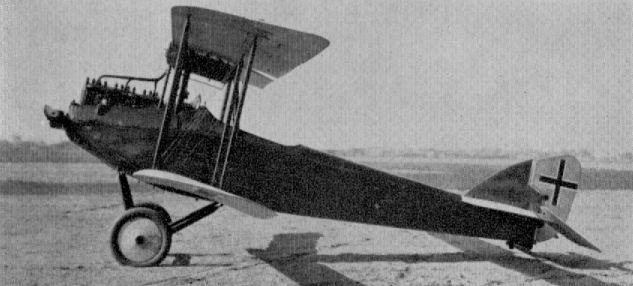
Germania C IV 1918
Goedecker B
This early 1915 type trainer became no more than a prototype. It was a perfectly orthodox wood and fabric machine, built first as a single-bay aircraft and later rebuilt with two-bay wings. Engine, 120 h.p. Mercedes D II.
This early 1915 type trainer became no more than a prototype. It was a perfectly orthodox wood and fabric machine, built first as a single-bay aircraft and later rebuilt with two-bay wings. Engine, 120 h.p. Mercedes D II.
Gotha LE 3
Although the Gotha LE 3 was a pre-war 1914 Taube design, a few saw operational service on scouting duties during the opening months of the var. Engine, 100 h.p. Mercedes D I. Span. 14.5 m. (47 ft. 7 in.). Length, 10.0 m. (32 ft. 9 3/4 in.). Area. 33.5 sq.m. (362 sq.ft.). Weights: Empty, 690 kg. (1,518 lb.). Loaded. 1.026 kg. (2.257 lb.). Speed, 96 km.hr. (60 m.p.h.). Climb, 800 m. (2.624 ft.) in 12 min.
Although the Gotha LE 3 was a pre-war 1914 Taube design, a few saw operational service on scouting duties during the opening months of the var. Engine, 100 h.p. Mercedes D I. Span. 14.5 m. (47 ft. 7 in.). Length, 10.0 m. (32 ft. 9 3/4 in.). Area. 33.5 sq.m. (362 sq.ft.). Weights: Empty, 690 kg. (1,518 lb.). Loaded. 1.026 kg. (2.257 lb.). Speed, 96 km.hr. (60 m.p.h.). Climb, 800 m. (2.624 ft.) in 12 min.
Gotha LD 2
Although similar to the LD la, the LD 2 actually preceded it, having been built in August 1914. It was used at the front for a few months, as were almost any reliable aircraft at this period. Engine, 100 h.p. Mercedes D I. Span, 14.5 m. (47 ft. 7 in.). Length, 7.5 m. (24 ft. 7 3/8 in.). Area. 46 sq.m. (497 sq.ft.). Weights: Empty, 735 kg. (1,617 lb.). Loaded, 1,127 kg. (2,479 lb.). Speed, 105 km.hr. (65.625 m.p.h.). Climb, 800 m. (2,624 ft.) in 12 min. Armament, none.
Although similar to the LD la, the LD 2 actually preceded it, having been built in August 1914. It was used at the front for a few months, as were almost any reliable aircraft at this period. Engine, 100 h.p. Mercedes D I. Span, 14.5 m. (47 ft. 7 in.). Length, 7.5 m. (24 ft. 7 3/8 in.). Area. 46 sq.m. (497 sq.ft.). Weights: Empty, 735 kg. (1,617 lb.). Loaded, 1,127 kg. (2,479 lb.). Speed, 105 km.hr. (65.625 m.p.h.). Climb, 800 m. (2,624 ft.) in 12 min. Armament, none.
Gotha LD 1a
Developed from the pre-war (April 1914) LD 1, the la was built in 1915. It was of orthodox wood and fabric construction except for steel-tube control surfaces. Engine, 100 h.p. Oberursel U I. Span, 14.5 m. (47 ft. 7 in.). Length, 7.4 m. (24 ft. 3 3/8 in.). Weights: Empty, 525 kg. (1,155 lb.). Loaded 917 kg. (2,017 lb.). Speed, 115 km.hr. (71.875 m.p.h.). Climb, 800 m. (2,624 ft.) in 8 min. Armament, none.
Gotha LD 5
Built in November 1914, this diminutive biplane was intended for fast scouting duty (Kavallerie Flugzeug). The undercarriage chassis is of interest, being virtually a single-strut structure with cable bracing forward and a light steel tube to the rear. The arched decking forward of the cockpit, housing the fuel tanks, is also noteworthy. Engine, 100 h.p. Oberursel U I.
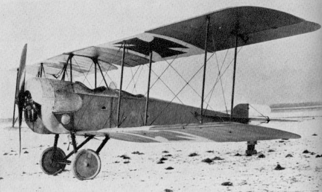
Gotha LD 1a
Gotha WD 1
Although a pre-war design, five WD 1 and 1a aircraft saw service during the early months of the war, on coastal patrol duties. In April 1914 a WD 1 flew from Warnemunde seaplane station to Denmark. Engine, 100 h.p. Gnome. Span, 14.1 m. (46 ft. 34 in.). Length, 10.3 m. (33 ft. 9 5/8 in.). Area, 50 sq.m. (540 sq.ft.). Weights: Empty, 900 kg. (1,980 lb.). Loaded, 1,220 kg. (2,684 lb.). Speed, 90 km.hr. (61.75 m.p.h.). Ceiling, 2,500 m. (8,200 ft.).
Gotha WD 2
Altogether eleven Gotha WD 2s were supplied to the Navy during 1915 and used on reconnaissance and patrol duties. The type was also supplied to Turkey, this version having a machine-gun mounted on top of the centre-section, which the observer stood up to operate. Engine, 150 h.p. Benz III. Span, 15.6 m. (51 ft. 2 1/4 in.). Length, 10.5 m. (34 ft. 5 1/2 in.). Area, 56 sq.m. (605 sq.ft.). Weights: Empty, 1,065 kg. (2,343 lb.). Loaded, 1,630 kg. (3,586 lb.). Speed, 112 km.hr. (70 m.p.h.). Ceiling, 3,000 m. (9,840 ft.). Armament, none.
Gotha Ursinus G.U.H. G I and U.W.D.
This unique aeroplane, to the design of Oskar Ursinus (editor of Flugsport), was built by Gothaer Waggonfabrik A.G., in both land and seaplane versions. The landplane first flew on 27th July 1915 and the seaplane early in 1916. Several of the former version were constructed and designated G I. A crew of three was carried, and the gunner in the front cockpit had an unparalleled field of fire. The idea of raising the fuselage was to enable the engines to be placed as close together as possible - airscrew tips almost touching - in order to retain a good degree of control in asymmetric flight should failure of either engine occur. In both types "handed" airscrews were employed.
Engines, two 150 h.p. Benz Bz III. Span, 20.3 m. (66 ft. 7 1/4 in.). Length. 12.1 m. (39 ft. 8 1/2 in.). Height, 4.0 m. (13 ft. 1 1/2 in.). Area, 82 sq.m. (885.6 sq.ft.). Weights: Empty, 1,860 kg. (4,092 lb.). Loaded, 2,830 kg. (6,226 lb.). Speed, 130 km.hr. (81.25 m.p.h.). Ceiling, 2,750 m. (9,020 ft.) in 34 min. Duration, 4 hr. (G.U.H. G I land machine.)
Armament, two Parabellum machine-guns, both types.
Gotha LD 6a
The LD 6a appeared in March 1915 and was designed (by Rosner) for long-distance reconnaissance and to carry a small bomb load. Of conventional wood and fabric construction, the LD 6a featured balanced tail in faces but plain ailerons. Engine was the 150 h.p. Benz Bz III, with radiators alongside the front (observer's) cockpit. Data was probably similar to that of LD 7.
Gotha LD 7
Another product of March 1915 was the LD 7 designed (by Burkhard) for standard reconnaissance duties. It was the last machine of the LD series. Engine, 120 h.p. Mercedes D II. Span, 12.4 m. (40 ft. 8 1/4 in.). Length, 8.4 m. (27 ft. 6 3/4 in.). Area, 39.5 sq.m. (467 sq.ft.). Weights: Empty, 725 kg. (1,595 lb.). Loaded, 1,125 kg. (2,475 lb.). Speed, 125 km.h (78.125 m.p.h.). Climb, 800 m. (2,624 ft.) in 8 1/2 min.
Gotha WD 3
Built in July 1915, this aircraft was to the twin-boom formula with a central nacelle housing the 160 h.p. Mercedes engine and pusher airscrew. The observer sat in the extreme nose and was armed with a machine-gun; a radio transmitter was also installed. Only a single aircraft (Marine No. 259) was supplied. Engine, 160 h.p. Mercedes D III. Span, 15.6 m. (51 ft. 2 1/4 in.). Area, 54 sq.m. (583 sq.ft.). Weights: Empty, 1,105 kg. (2,431 lb.). Loaded, 1,710 kg. (3,762 lb.). Speed, 100 km.hr. (62.5 m.p.h.). Armament, one manually operated Parabellum machine-gun in nose.
Built in July 1915, this aircraft was to the twin-boom formula with a central nacelle housing the 160 h.p. Mercedes engine and pusher airscrew. The observer sat in the extreme nose and was armed with a machine-gun; a radio transmitter was also installed. Only a single aircraft (Marine No. 259) was supplied. Engine, 160 h.p. Mercedes D III. Span, 15.6 m. (51 ft. 2 1/4 in.). Area, 54 sq.m. (583 sq.ft.). Weights: Empty, 1,105 kg. (2,431 lb.). Loaded, 1,710 kg. (3,762 lb.). Speed, 100 km.hr. (62.5 m.p.h.). Armament, one manually operated Parabellum machine-gun in nose.
Gotha WD 5
There is no record of a Gotha WD 4 and the WD 5 was only a one-off type. It was, in fact, a modified WD 2 and retained the same Marine No. 118. The span was reduced to a two-bay cellule, and a 160 h.p. Mercedes engine replaced the Benz. Of interest are the two narrow strip-type radiators, which were attached to the front centre-section struts. This machine was retained by Capt. Langfeld, C.O. of Haltenau naval air station, as his personal aircraft - even when he was later transferred to Constantinople. Engine, 160 h.p. Mercedes D III. Span, 12.5 m. (41 ft. 0 1/4 in.). Length 10.3 m. (33 ft. 9 5/8 in.). Area, 42.5 sq.m. (459 sq.ft.). Weights: Empty, 900 kg. (1,980 lb.). Loaded, 1,465 kg. (3,223 lb.). Speed, 126 km.hr. (78.5 m.p.h.). Armament, none.
Gotha WD 9
Appearing in February 1916, the WD 9 was largely a development of the WD 5. Only a single machine (fitted with a 160 h.p. Mercedes D III) was supplied to the German Navy. However, several aircraft (with the 150 h.p. Benz) were supplied to the Turkish Government. Engine, 160 h.p. Mercedes D III. Span, 15.0 m. (49 ft. 2 5/8 in.). Length, 9.8 m. (32 ft. 1 7/8 in.) Height, 3.8 m. (12 ft. 5 5/8 in.). Area, 51.3 sq.m. (554 sq.ft.). Weights: Empty, 1,040 kg. (2,288 lb.). Loaded, 1,490 kg. (3,278 lb.). Speed, 136 km.hr. (85 m.p.h.). Climb, 1,000 m. (3,280 ft.) in 10 min. Duration, 3 1/2 hr. Armament, one manually operated Parabellum machine-gun in rear cockpit.
Gotha G II and G III
The Gotha G II and G III of 1916 were the first of Burkhard's twin-engined designs, and differed only in interior detail. A small number was built and used on the Western Front, one unit to be so equipped being Bogohl III at Ghent. Engines, two 260 h.p. Mercedes D IVa. Span, 23.7 m. (77 ft. 9 1/4 in.). Length, 11.79 m. (38 ft. 8 1/4 in.). Area, 89.5 sq.m. (967 sq.ft.). Weights: Empty, 2,182 kg. (4,800 lb.). Loaded, 3 192 kg. (7,022 lb.). Speed, 148 km.hr. (92.5 m.p.h.). Climb, 3,000 m. (9,840 ft.) in 28 min., 4,000 m. (13,120 ft.) in 41 min. Armament, two Parabellum machine-guns for nose and dorsal/ventral positions.
The Gotha G II and G III of 1916 were the first of Burkhard's twin-engined designs, and differed only in interior detail. A small number was built and used on the Western Front, one unit to be so equipped being Bogohl III at Ghent. Engines, two 260 h.p. Mercedes D IVa. Span, 23.7 m. (77 ft. 9 1/4 in.). Length, 11.79 m. (38 ft. 8 1/4 in.). Area, 89.5 sq.m. (967 sq.ft.). Weights: Empty, 2,182 kg. (4,800 lb.). Loaded, 3 192 kg. (7,022 lb.). Speed, 148 km.hr. (92.5 m.p.h.). Climb, 3,000 m. (9,840 ft.) in 28 min., 4,000 m. (13,120 ft.) in 41 min. Armament, two Parabellum machine-guns for nose and dorsal/ventral positions.

Gotha G.III 398/16; differences between the G.II and G.III were slight and only visible from certain viewpoints.
The Gotha G.III was developed from the G.II and like all subsequent operational Gothas used the more powerful 260 hp Mercedes D.IVa six-cylinder engines.
The Germans had been using aircraft for strategic bombing from 1915 and by 1916 a range of new types was available such as this Gotha GIII - although only used in small numbers on the Western Front and with no great measure of success.
Gotha G IV and G V
The Gotha was without doubt the most legendary twin-engined bomber of the First World War. The name came to be applied generically (and inaccurately) to all large enemy aircraft, in much the same way that "Handley Page" was applied to all and sundry Allied twin-engine machines. It was largely through the use of the Gotha in daylight raids on Great Britain that these aircraft became so widely publicized and were mentioned only with apprehension. The Gotha G.IV and G.V became the main production variants, having been developed from the earlier G 11 series of 1916, which were produced only in small numbers. The G.IV and G.V were manufactured by both the parent firm and sundry sub-contractors.
Together with the Friedrichshafen G.III, the Gothas shared the brunt of the long-range bombing attacks from 1917 onwards. An outstanding feature of the G.IV and G.V was the "sting in the tail" whereby the rear gunner was able to fire not only upwards and backwards but downwards too, through a specially designed "tunnel" in the fuselage bottom. This firing position had been tried in the earlier Gotha G.III, but the gun had to be operated by the gunner adopting a prone position and firing through a trapdoor in the fuselage bottom. In the G.IV and G.V the plywood-lined tunnel was aligned with a V-shaped opening in the top decking so that the gun, on a normal mounting, could be sighted and fired through the fuselage, backwards and downwards, through an arc of 25 deg. laterally and 60 deg. vertically, although a prone position could also be adopted. Considerable toll was taken of Allied machines until effective evasive tactics had been evolved.
Apart from this novel firing arrangement, the Gotha G.IV and G.V were quite conventional airframes, and the fuselage, unlike the contemporary Friedrichshafen G.III, was a one-piece wooden structure of spruce longerons and spacers. Although completely plywood-skinned, the basic structure was still braced in all bays with stranded steel cables. A gunner's cockpit was situated in the extreme nose, immediately aft of which sat the pilot on the port side of the fuselage. Beside him was arranged a folding seat for another crew member. Between the pilot's cockpit aft of the wings were located the main fuel tanks, which occupied the full width of the fuselage, preventing any interchange of crew positions in flight. Bulkheads were cut away extensively, however, which points to the fact that initially the design had intended inter-communication.
Of three-bay layout, the upper wings were composed of two panels joined at the center with steel wedges securing interlocking rectangular staples. The lower wings had a center-section portion to which were attached the engine bearers, struts and undercarriage chassis, each side being an independent and separate unit. These sections were plywood-covered on both surfaces. Based on two spruce main-spars of channelled I-section, additionally walled with 4 mm. birch ply and fabric wrapped, the fabric covered wings were swept throughout their length at an angle of 4 deg. Ribs of ply, extensively fretted for lightening purposes, were flanged with solid timber and tacked to the spars. All interplane struts were of steel tube with three-ply fairings attached. Inboard the trailing edges of the wings were all cut back to allow airscrew clearance for the pusher-arranged twin 260 h.p. Mercedes D.IVa engines. Ailerons of welded steel tube were fitted to all four wingtips, those on the upper wing having a large horn balance. They were linked with a strut and actuated by a crank lever attached to the top ailerons.
The complete empennage was fabricated from light-gauge steel tube and fabric covered. Only the rudder was balanced, and its size, compared with the fin, was considerable. Streamlined steel-tube struts rigidly braced the components to the fuselage.
Each separate undercarriage chassis was fitted with two wheels which were attached to the main axle and sprung with long tension springs, unusually mounted inside the main struts. In the Gotha G.Vb a front pair of wheels was added to each chassis, forming an auxiliary attachment to facilitate night landings and prevent nosing over. An extremely rugged tailskid with steel reinforcing spine and shoe completed the undercarriage gear.
Bombs were stowed externally on removable racks, and were arranged and fitted according to their size and the requirements of the operation.
The emergence of the Gotha G.IV in the autumn of 1916 coincided with a realization of the Zeppelin airship's limitations as a raiding weapon, and it made the aeroplane bombing raids on England, for which the "Ostend Carrier-Pigeon" Squadron had been formed as early as November 1914, a practical possibility. Thirty Gotha G.IVs were issued to Heavy Bomber Squadron No. 3, commanded by Hauptmann Brandenburg, in the spring of 1917. They were based at St. Denis Westrem (Flights 13 and 14) and Gontrode (Flights 15 and 16). Two more flights (Nos. 17 and 18) were added in July 1917.
In the daylight raids on England (25th May to 22nd August 1917) the Gothas achieved a remarkable degree of success with, initially, a surprisingly low casualty rate. The reason for this was two-fold. The Gotha's excellent 260 h.p. Mercedes engines enabled it to operate in the region of 15,000 ft. and, as the English defenses lacked adequate early warning facilities, was able to approach and release its bombs before Home defense aircraft could attain the same altitude. By the time such fighters as were then available (modified B.E., Sopwith Pups, Martinsydes, etc.) had laboriously clambered to their ceilings, the raiding aircraft were well on their way back across the North Sea. No significant material damage was achieved, but the effect on the public was such that the Government was forced to withdraw operational fighter squadrons from France, including the famous No. 56 Squadron, to combat the daylight raids. With the subsequent improvement of the warning system and the advent of the Bristol Fighter and Sopwith Camel defense units, daylight raids became impossible without disproportionate losses and the Gothas reverted to night raids from 3rd September 1917 onwards. The night attacks ended in May 1918. Altogether, the Gothas of Bombengeschwader 3 dropped 84,745 kg. of bombs on England in twenty-two raids. Twenty-four Gothas were destroyed by Allied defenses and a further thirty-seven lost in accidents.
Capt. J. B. McCudden, V.C., had a brush with the daylight raiders while serving as an instructor at Joyce Green: strangely enough, it was on 5th July 1917, the day after No. 56 Squadron had returned to France. McCudden had his unarmed instructional Sopwith Pup fitted with a Lewis gun to fire over the airscrew and the under-surfaces of his aircraft painted blue to render it less visible should he be able to get above the Gothas to put in an attack. The warning came about 10 a.m., and McCudden immediately took off and climbed towards the south of the Thames, ultimately arriving over Southend at some 16,000 ft. Flying west along the estuary, attracted by A.A. bursts, he saw some twenty bombers in good formation returning east. Having altitude to spare, he waited for the formation to pass before diving on the rearmost machine firing a complete drum of forty-seven rounds. Misjudging the dive, McCudden had to pull out to avoid the Gotha so suddenly as to break his seat bearers. Pulling up for another attack, he dived to within 300 ft. on the Gotha's starboard quarter, then suddenly changed over to his port rear, closing to 150 ft. and finishing another drum before the enemy gunner could swing his gun to the opposite side. However, neither attack produced any visible effect. Putting on his third and last drum, McCudden again repeated the maneuver of changing from side to side to disconcert the gunner, and this time saw his tracers striking about the fuselage and wings, but was disappointed to achieve no more effect than for the Gotha to shove down his nose a little. Now out of ammunition, he could do no more than fly alongside the bomber at a discreet distance, screened from enemy fire by the Gotha's own wings, in the hope of distracting the attention of the gunners so that some of the other defense machines that had now appeared on the scene might perhaps get in an attack. After 25 minutes his vigilance relaxed, and one of the enemy gunners put a good burst through McCudden's Pup, one bullet smashing the windscreen.
Description: Twin-engined long-range bomber. Crew of three.
Manufacturers: Gothaer Waggonfabrik A.G. Gotha (Go.).
Sub-contractors: Luft Verkehrs G.m.b.H. (G. IV) (Lvg.)
Siemens Schuckert Werke G.m.b.H. 80 a/c (G.IV) (Ssw.)
Power Plant: Two 260 h.p. Mercedes D. IVa 6 cylinder in-line water-cooled engines.
Dimensions:
Span 23.7 m. (77 ft. 9 1/4 in.)
Length 11.86 m. (38 ft. 11 in.)
Height 4.3 m. (14 ft 1 1/4 in.)
Area 89.5 sq.m. (966.6 sq.ft.)
Weights:
Empty 2,400 kg. (5,280 lb.)
Loaded 3,635 kg. (7,997 lb.)
Performance:
Max speed 140 km.h. (87.5 m.p.h.) at 12,000 ft.
Climb to 3,000 m. 28 min.
Ceiling 6,500 m. (21,320 ft.) in 52.5 min.
Range 305 miles.
Armament: Two manually operated Parabellum machine-guns in nose and rear cockpits.
Bomb load varied from 300 to 500 kg. (660 lb. to 1,100 lb.) to suit operational requirements.
Six 50-kg. (110 lb.) bombs were usually carried in the daylight raids on England.
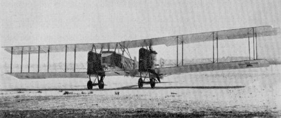
Gotha G IV.
Ursinus Seaplane
Another most interesting design of Ursinus was his seaplane fighter of 1916, with retractable floats designed to lie flat against the lower part of the fuselage when cranked up by the pilot. It was an attempt to overcome the inherent disadvantages of drag and manoeuvrability which attended float planes generally and fighters in particular. To improve manoeuvrability the engine was located on the centre of gravity and the airscrew driven through an extension shaft. The general cleanliness of the aeroplane, for the 1916 period, was remarkable. Unfortunately the prototype was destroyed during trials, and the estimated top speed of 200 km.hr. (124 m.p.h.) had not been achieved by that time. Engine, 150 h.p. Benz Bz III. Span, 9.00 m. (29 ft. 6 3/8 in.). Length, 7.77m. (25ft. 6 1/2 in.). Height, 2.9 m. (9 ft. 6 1/4 in.) floats down; 2.0 m. (6 ft. 6 3/4 in.) floats retracted. Weights: Empty, 749.5 kg. (1,649 lb.). Loaded, 1,002 kg. (2,205 lb.).
Another most interesting design of Ursinus was his seaplane fighter of 1916, with retractable floats designed to lie flat against the lower part of the fuselage when cranked up by the pilot. It was an attempt to overcome the inherent disadvantages of drag and manoeuvrability which attended float planes generally and fighters in particular. To improve manoeuvrability the engine was located on the centre of gravity and the airscrew driven through an extension shaft. The general cleanliness of the aeroplane, for the 1916 period, was remarkable. Unfortunately the prototype was destroyed during trials, and the estimated top speed of 200 km.hr. (124 m.p.h.) had not been achieved by that time. Engine, 150 h.p. Benz Bz III. Span, 9.00 m. (29 ft. 6 3/8 in.). Length, 7.77m. (25ft. 6 1/2 in.). Height, 2.9 m. (9 ft. 6 1/4 in.) floats down; 2.0 m. (6 ft. 6 3/4 in.) floats retracted. Weights: Empty, 749.5 kg. (1,649 lb.). Loaded, 1,002 kg. (2,205 lb.).
Gotha Ursinus G.U.H. G I and U.W.D.
This unique aeroplane, to the design of Oskar Ursinus (editor of Flugsport), was built by Gothaer Waggonfabrik A.G., in both land and seaplane versions. The landplane first flew on 27th July 1915 and the seaplane early in 1916. Several of the former version were constructed and designated G I. A crew of three was carried, and the gunner in the front cockpit had an unparalleled field of fire. The idea of raising the fuselage was to enable the engines to be placed as close together as possible - airscrew tips almost touching - in order to retain a good degree of control in asymmetric flight should failure of either engine occur. In both types "handed" airscrews were employed.
Only a single seaplane (No. 120) was built, and was ultimately used as a school machine for torpedo crews.
Engines, two 160 h.p. Mercedes D III. Span, 20.3 m. (66 ft. 7 1/4 in.). Length, 14.2 m. (46 ft. 7 1/8 in.). Area, 82 sq.m. (885.6 sq.ft.). Weights: Empty, 1,940 kg. (4,268 lb.). Loaded, 2,830 kg. (6,849 lb.). Speed 138 km.hr. (86.125 m.p.h.). Climb, 1,000 m. (3,280 ft.) in 8 min. (U.W.D Seaplane data.)
Armament, two Parabellum machine-guns, both types.
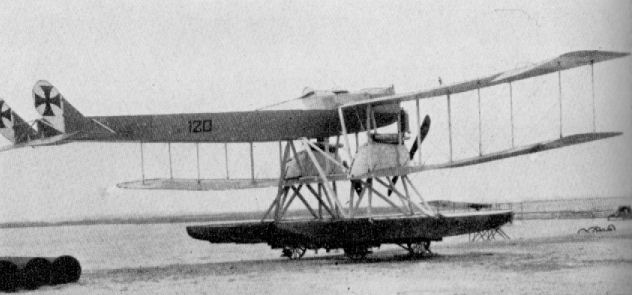
Gotha Ursinus U.W.D.
Gotha WD 7
During 1916, eight twin-engined WD 7s were built and used as school machines on which crews practised torpedo-dropping tactics prior to going on to the larger operational aircraft. Engines, two 120 h.p. Mercedes D II. Span, 160 m. (52 ft. 6 in.). Length, 11.3 m. (37 ft. 1 in.). Height, 3.585 m. (11 ft. 9 1/8 in.). Area, 55.5 sq.m. (599 sq.ft.). Weights: Empty, 1,440 kg. (3,168 lb.). Loaded, 1,970 kg. (4,334 lb.). Speed, 136 km.hr. (85 m.p.h.) Ceiling, 4,000 m. (13,120 ft.).
During 1916, eight twin-engined WD 7s were built and used as school machines on which crews practised torpedo-dropping tactics prior to going on to the larger operational aircraft. Engines, two 120 h.p. Mercedes D II. Span, 160 m. (52 ft. 6 in.). Length, 11.3 m. (37 ft. 1 in.). Height, 3.585 m. (11 ft. 9 1/8 in.). Area, 55.5 sq.m. (599 sq.ft.). Weights: Empty, 1,440 kg. (3,168 lb.). Loaded, 1,970 kg. (4,334 lb.). Speed, 136 km.hr. (85 m.p.h.) Ceiling, 4,000 m. (13,120 ft.).
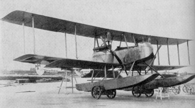
Gotha WD 7
Gotha WD 8
This machine, built in December 1915, was virtually a single-engined version of the WD 7, the same wing cellule, float chassis and tail assembly being used. It was intended for armed reconnaissance, but only a single example (No. 476) was produced. Engine, 240 h.p. Maybach Mb IV. Span, 160 m. (52 ft. 6 in.). Length, 11.2 m. (36 ft. 9 in.). Area, 59 sq.m. (637 sq.ft.). Weights: Empty, 1,250 kg. (2,750 lb.). Loaded. 1,770 kg. (3,894 lb.). Speed, 130 km.hr. (81.25 m.p.h.). Ceiling, 4,500 m. (14,760 ft.). Armament, one manually operated Parabellum machine-gun in rear cockpit.
This machine, built in December 1915, was virtually a single-engined version of the WD 7, the same wing cellule, float chassis and tail assembly being used. It was intended for armed reconnaissance, but only a single example (No. 476) was produced. Engine, 240 h.p. Maybach Mb IV. Span, 160 m. (52 ft. 6 in.). Length, 11.2 m. (36 ft. 9 in.). Area, 59 sq.m. (637 sq.ft.). Weights: Empty, 1,250 kg. (2,750 lb.). Loaded. 1,770 kg. (3,894 lb.). Speed, 130 km.hr. (81.25 m.p.h.). Ceiling, 4,500 m. (14,760 ft.). Armament, one manually operated Parabellum machine-gun in rear cockpit.
Gotha G IV and G V
The Gotha was without doubt the most legendary twin-engined bomber of the First World War. The name came to be applied generically (and inaccurately) to all large enemy aircraft, in much the same way that "Handley Page" was applied to all and sundry Allied twin-engine machines. It was largely through the use of the Gotha in daylight raids on Great Britain that these aircraft became so widely publicized and were mentioned only with apprehension. The Gotha G.IV and G.V became the main production variants, having been developed from the earlier G 11 series of 1916, which were produced only in small numbers. The G.IV and G.V were manufactured by both the parent firm and sundry sub-contractors.
Together with the Friedrichshafen G.III, the Gothas shared the brunt of the long-range bombing attacks from 1917 onwards. An outstanding feature of the G.IV and G.V was the "sting in the tail" whereby the rear gunner was able to fire not only upwards and backwards but downwards too, through a specially designed "tunnel" in the fuselage bottom. This firing position had been tried in the earlier Gotha G.III, but the gun had to be operated by the gunner adopting a prone position and firing through a trapdoor in the fuselage bottom. In the G.IV and G.V the plywood-lined tunnel was aligned with a V-shaped opening in the top decking so that the gun, on a normal mounting, could be sighted and fired through the fuselage, backwards and downwards, through an arc of 25 deg. laterally and 60 deg. vertically, although a prone position could also be adopted. Considerable toll was taken of Allied machines until effective evasive tactics had been evolved.
Apart from this novel firing arrangement, the Gotha G.IV and G.V were quite conventional airframes, and the fuselage, unlike the contemporary Friedrichshafen G.III, was a one-piece wooden structure of spruce longerons and spacers. Although completely plywood-skinned, the basic structure was still braced in all bays with stranded steel cables. A gunner's cockpit was situated in the extreme nose, immediately aft of which sat the pilot on the port side of the fuselage. Beside him was arranged a folding seat for another crew member. Between the pilot's cockpit aft of the wings were located the main fuel tanks, which occupied the full width of the fuselage, preventing any interchange of crew positions in flight. Bulkheads were cut away extensively, however, which points to the fact that initially the design had intended inter-communication.
Of three-bay layout, the upper wings were composed of two panels joined at the center with steel wedges securing interlocking rectangular staples. The lower wings had a center-section portion to which were attached the engine bearers, struts and undercarriage chassis, each side being an independent and separate unit. These sections were plywood-covered on both surfaces. Based on two spruce main-spars of channelled I-section, additionally walled with 4 mm. birch ply and fabric wrapped, the fabric covered wings were swept throughout their length at an angle of 4 deg. Ribs of ply, extensively fretted for lightening purposes, were flanged with solid timber and tacked to the spars. All interplane struts were of steel tube with three-ply fairings attached. Inboard the trailing edges of the wings were all cut back to allow airscrew clearance for the pusher-arranged twin 260 h.p. Mercedes D.IVa engines. Ailerons of welded steel tube were fitted to all four wingtips, those on the upper wing having a large horn balance. They were linked with a strut and actuated by a crank lever attached to the top ailerons.
The complete empennage was fabricated from light-gauge steel tube and fabric covered. Only the rudder was balanced, and its size, compared with the fin, was considerable. Streamlined steel-tube struts rigidly braced the components to the fuselage.
Each separate undercarriage chassis was fitted with two wheels which were attached to the main axle and sprung with long tension springs, unusually mounted inside the main struts. In the Gotha G.Vb a front pair of wheels was added to each chassis, forming an auxiliary attachment to facilitate night landings and prevent nosing over. An extremely rugged tailskid with steel reinforcing spine and shoe completed the undercarriage gear.
Bombs were stowed externally on removable racks, and were arranged and fitted according to their size and the requirements of the operation.
The emergence of the Gotha G.IV in the autumn of 1916 coincided with a realization of the Zeppelin airship's limitations as a raiding weapon, and it made the aeroplane bombing raids on England, for which the "Ostend Carrier-Pigeon" Squadron had been formed as early as November 1914, a practical possibility. Thirty Gotha G.IVs were issued to Heavy Bomber Squadron No. 3, commanded by Hauptmann Brandenburg, in the spring of 1917. They were based at St. Denis Westrem (Flights 13 and 14) and Gontrode (Flights 15 and 16). Two more flights (Nos. 17 and 18) were added in July 1917.
In the daylight raids on England (25th May to 22nd August 1917) the Gothas achieved a remarkable degree of success with, initially, a surprisingly low casualty rate. The reason for this was two-fold. The Gotha's excellent 260 h.p. Mercedes engines enabled it to operate in the region of 15,000 ft. and, as the English defenses lacked adequate early warning facilities, was able to approach and release its bombs before Home defense aircraft could attain the same altitude. By the time such fighters as were then available (modified B.E., Sopwith Pups, Martinsydes, etc.) had laboriously clambered to their ceilings, the raiding aircraft were well on their way back across the North Sea. No significant material damage was achieved, but the effect on the public was such that the Government was forced to withdraw operational fighter squadrons from France, including the famous No. 56 Squadron, to combat the daylight raids. With the subsequent improvement of the warning system and the advent of the Bristol Fighter and Sopwith Camel defense units, daylight raids became impossible without disproportionate losses and the Gothas reverted to night raids from 3rd September 1917 onwards. The night attacks ended in May 1918. Altogether, the Gothas of Bombengeschwader 3 dropped 84,745 kg. of bombs on England in twenty-two raids. Twenty-four Gothas were destroyed by Allied defenses and a further thirty-seven lost in accidents.
Capt. J. B. McCudden, V.C., had a brush with the daylight raiders while serving as an instructor at Joyce Green: strangely enough, it was on 5th July 1917, the day after No. 56 Squadron had returned to France. McCudden had his unarmed instructional Sopwith Pup fitted with a Lewis gun to fire over the airscrew and the under-surfaces of his aircraft painted blue to render it less visible should he be able to get above the Gothas to put in an attack. The warning came about 10 a.m., and McCudden immediately took off and climbed towards the south of the Thames, ultimately arriving over Southend at some 16,000 ft. Flying west along the estuary, attracted by A.A. bursts, he saw some twenty bombers in good formation returning east. Having altitude to spare, he waited for the formation to pass before diving on the rearmost machine firing a complete drum of forty-seven rounds. Misjudging the dive, McCudden had to pull out to avoid the Gotha so suddenly as to break his seat bearers. Pulling up for another attack, he dived to within 300 ft. on the Gotha's starboard quarter, then suddenly changed over to his port rear, closing to 150 ft. and finishing another drum before the enemy gunner could swing his gun to the opposite side. However, neither attack produced any visible effect. Putting on his third and last drum, McCudden again repeated the maneuver of changing from side to side to disconcert the gunner, and this time saw his tracers striking about the fuselage and wings, but was disappointed to achieve no more effect than for the Gotha to shove down his nose a little. Now out of ammunition, he could do no more than fly alongside the bomber at a discreet distance, screened from enemy fire by the Gotha's own wings, in the hope of distracting the attention of the gunners so that some of the other defense machines that had now appeared on the scene might perhaps get in an attack. After 25 minutes his vigilance relaxed, and one of the enemy gunners put a good burst through McCudden's Pup, one bullet smashing the windscreen.
Description: Twin-engined long-range bomber. Crew of three.
Manufacturers: Gothaer Waggonfabrik A.G. Gotha (Go.).
Power Plant: Two 260 h.p. Mercedes D. IVa 6 cylinder in-line water-cooled engines.
Dimensions:
Span 23.7 m. (77 ft. 9 1/4 in.)
Length 11.86 m. (38 ft. 11 in.)
Height 4.3 m. (14 ft 1 1/4 in.)
Area 89.5 sq.m. (966.6 sq.ft.)
Weights:
Empty 2,740 kg. (6,028 lb.)
Loaded 3,975 kg. (8,745 lb.)
Performance:
Max speed 140 km.h. (87.5 m.p.h.) at 12,000 ft.
Climb to 3,000 m. 28 min.
Ceiling 6,500 m. (21,320 ft.) in 52.5 min.
Range 305 miles.
Armament: Two manually operated Parabellum machine-guns in nose and rear cockpits.
Bomb load varied from 300 to 500 kg. (660 lb. to 1,100 lb.) to suit operational requirements.
Six 50-kg. (110 lb.) bombs were usually carried in the daylight raids on England.
Gotha G Vb
Towards the end of the G V production a modified version, the G Va with a compound tail assembly, was introduced, and this type was further modified, by the addition of extra landing wheels to the twin undercarriage chassis, into the G Vb. The type saw service during 1918 in limited numbers, and was the last of the Gotha "classic" twins. Engines, two 260 h.p. Mercedes D IVa. Span, 23.7 m. (77 ft. 9 1/4 in.). Length, 12.4 m. (40 ft. 8 1/4 in.) unconfirmed. Area, 89.5 sq.m. (967 sq.ft.). Weights: Empty, 2,950 kg. (6,490 lb.). Loaded,4,550kg.(10,010 lb.). Speed, 135km.hr.(84.35m.p.h.).

Gotha G V.

Gotha G Vb
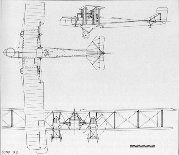
Gotha G VI
Based on the standard Gotha G V wing cellule, the G VI was probably the world's first asymmetric aircraft. The fuselage, offset to port, housed a normally mounted engine in the nose driving a tractor airscrew, the nacelle to starboard housing the other engine driving a pusher airscrew. After some successful flights, the machine was wrecked and was developed no further. Engines, two 260 h.p. Mercedes D IVa. Span, 23.7 m. (77 ft. 9 1/4 in.). Length, 12.4 m. (40 ft. 8 1/4 in.). Area, 89.5 sq.m. (967 sq.ft.).
Based on the standard Gotha G V wing cellule, the G VI was probably the world's first asymmetric aircraft. The fuselage, offset to port, housed a normally mounted engine in the nose driving a tractor airscrew, the nacelle to starboard housing the other engine driving a pusher airscrew. After some successful flights, the machine was wrecked and was developed no further. Engines, two 260 h.p. Mercedes D IVa. Span, 23.7 m. (77 ft. 9 1/4 in.). Length, 12.4 m. (40 ft. 8 1/4 in.). Area, 89.5 sq.m. (967 sq.ft.).
Gotha WD 11
The WD 11 was the next development in the twin-engined torpedo aircraft series after the WD 7. It was a considerably bigger aeroplane, and its engines drove pusher airscrews. Some thirteen aircraft of this type were delivered between March and July 1917. Engines, two 160 h.p. Mercedes D III. Span, 22.51 m. (73 ft. 10 3/8 in.). Length, 13.43 m. (44 ft. 0 7/8 in.). Height, 4.75 m. (15 ft. 1 7/8 in.). Area, 103.4 sq.m. (1,117 sq.ft.). Weights: Empty, 2,437 kg. (5,361 lb.). Loaded, 3,583 kg. (7,883 lb.). Speed 120 km.hr. (75 m.p.h.). Climb, 1,000 m. (3,280 ft.) in 12 min. Armament, torpedo carried under fuselage; one Parabellum machine-gun in nose.
The WD 11 was the next development in the twin-engined torpedo aircraft series after the WD 7. It was a considerably bigger aeroplane, and its engines drove pusher airscrews. Some thirteen aircraft of this type were delivered between March and July 1917. Engines, two 160 h.p. Mercedes D III. Span, 22.51 m. (73 ft. 10 3/8 in.). Length, 13.43 m. (44 ft. 0 7/8 in.). Height, 4.75 m. (15 ft. 1 7/8 in.). Area, 103.4 sq.m. (1,117 sq.ft.). Weights: Empty, 2,437 kg. (5,361 lb.). Loaded, 3,583 kg. (7,883 lb.). Speed 120 km.hr. (75 m.p.h.). Climb, 1,000 m. (3,280 ft.) in 12 min. Armament, torpedo carried under fuselage; one Parabellum machine-gun in nose.
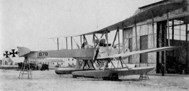
Gotha WD 11
Gotha WD 12
Only a single specimen (No. 944) of this unarmed patrol seaplane was supplied to the German Navy, although other aircraft of this type were built for Turkey. Turkish machines were railed to Herkulesbad in Hungary, erected and flown across Rumania to Lom-Polanka in Bulgaria, where they were again transported to Constantinople. Engine, 160 h.p. Mercedes DIII. Span, 150 m. (49 ft. 2 5/8 in.). Length, 10.0 m. (32 ft. 9 3/4 in.). Height 3.825 m. (12 ft. 6 1/2 in.). Area, 54 sq.m. (583 sq.ft.). Weights: Empty 1,000 kg. (2,200 lb.). Loaded, 1,550 kg. (3,410 lb.). Speed, 141 km.hr (88.125 m.p.h.). Climb, 1,000 m. (3,280 ft.) in 7.5 min. Duration, 5 1/2 hr. Armament, none.
Gotha WD 13
This patrol seaplane was a development of the WD 9. None were used by Germany, those that were built were supplied to the Turkish Government during 1917. Engine, 150 h.p. Benz Bz III. Span, 14.6 m. (47 ft. 10 7/8 in.). Length, 10.068 m. (33 ft. 0 1/2 in.). Height, 3.74 m. (12 ft. 3 1/4 in.). Area, 49 sq.m. (529 sq.ft.). Weights: Empty, 1,061 kg. (2,334 lb.). Loaded, 1.463 kg. (3,219 lb.). Speed, 131.5 km.hr. (82.25 m.p.h.). Climb, 1,000 m. (3,280 ft.) in 9 min. Duration, 3 hr. Armament, one manually operated Parabellum machine-gun in rear cockpit.
Gotha WD 15
Built towards the end of 1917, the WD 15 was little more than an enlarged WD 12 with ply-skinned fuselage and fin. It was the most powerful and also the last single-engined machine to be supplied by Gotha to the German Navy. Only two were built, Nos. 842 and 843. Engine, 260 h.p. Mercedes D IVa. Span, 17.2 m. (56 ft. 5 1/4 in.). Length, 11.2 m. (36 ft. 9 in.). Area, 64.5 sq.m. (697 sq.ft.). Weights: Empty, 1,545 kg. (3,399 lb.). Loaded, 2,300 kg. (5,060 lb.). Speed, 152 km.hr. (95 m.p.h.). Ceiling, 4,200 m. (13,780 ft.). Armament, none.
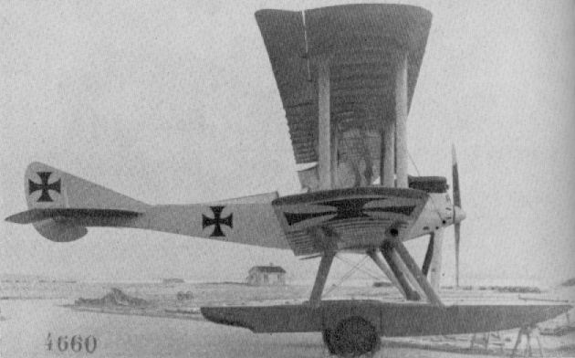
Gotha WD 12
Gotha W.D. 14
Although the Gotha firm was principally famous for its twin-engined bombers, it also produced some eighteen types of twin-float seaplane. The majority were no more than one-off prototypes, and apart from a small production batch of thirteen W.D. 11s, the only seaplane to be produced in any quantity was the twin-engined W.D. 14. This aircraft had been designed as a torpedo attack machine, and some sixty-nine examples were built.
The W.D. 14 was developed from the earlier, and smaller, W.D. 7 and W.D. 11 prototypes and conformed to an orthodox layout. The fuselage was basically a rectangular braced box-girder of spruce longerons and spacers with fabric-wrapped plywood-veneer covering. A rounded decking was incorporated on top of the fuselage forward and also underneath (as far aft as the trailing edge) to partially fair in the torpedo slung under the belly in a special dropping gear. The pilot was located back under the wings, side-by-side with the torpedo-man, who went forward to the nose cockpit to superintend the actual release of the missile. A further gunner's cockpit was located behind the pilot. The long two-step floats were carried on a complex strut chassis, designed without any spreader struts or wires between the floats to allow the torpedo to fall clear. Each float chassis therefore had to be an independent structure.
The angular tailplane was attached to the top longerons and was fitted with a one-piece, unbalanced elevator. Twin fins and twin horn-balanced rudders gave the empennage a distinctive profile; these surfaces were mounted as "end plates" on the extremities of the tailplane, extending both above and below, and were braced with light steel-tube struts. One aircraft also had a centre fin.
The centre-section of the three-bay wing structure embraced the mounting of the two 200 h.p. Benz Bz IV engines which were located directly on the lower wing as normal tractor units. The engines were additionally braced to the wing spars with streamlined steel-tube struts. Large frontal radiators were slung well above the cylinder-heads, and the engines themselves were well cowled in except for the upper part of the cylinders. A generous cutout was made in the upper centre-section in an endeavour to improve the pilot's upward field of vision.
An unusual feature of the outer wing panels, which were arranged to fold from the centre-section, was the taper of some 5° on the leading edge only. The wings themselves were based on the conventional twin main spar structure, the spars also being angled back at some 5° and the spruce-flanged plywood ribs, of a high lift section, were closely spaced to ensure as little aerofoil section loss as possible. The horn-balanced ailerons were hinged to an auxiliary spar parallel to the main spars.
No great success was achieved with torpedo attacks. The W.D. 14s were largely under-powered when loaded, and only pilots of exceptional skill were able to make suitable attack runs and torpedo drops from a height of some 20-30 ft. A long course of training had to be undergone by both pilot and torpedo-man, and eventual results in no way justified the efforts involved. After the first two torpedo attacks from North Sea bases and in the Gulf of Riga, the Allied counter-measures became so effective as to negative much chance of success. As a result, in the last year of the war, torpedo-carrying machines were abandoned, as losses far outweighed results.
In order not to waste useful airframes, torpedo aircraft were modified to undertake long-range reconnaissance duties over the North Sea in an endeavour to find an efficient substitute for the airship, which, during 1917, had become too vulnerable. Jettisonable fuel tanks fitted in the torpedo slings enabled flights of upwards of ten hours to be achieved. The seaplanes were unable to remain airborne on one engine even after the auxiliary fuel tank had been discarded. On having to alight on any surface other than a near flat-calm, they soon broke up. They were also tried in the role of mine-layers without success, but before being given up altogether were employed for a short time as coastal convoy escorts.
TECHNICAL DATA
Purpose: Twin-engined torpedo aircraft.
Manufacturer: Gothaer Waggonfabrik A.G. (Gotha.).
Power Plant: Two 200 h.p. Benz Bz IV 6 cylinder in-line water-cooled engines.
Dimensions: Span, 25.5 m. (83 ft. 8 in.). Length, 14.45 in. (47 ft. 5 in.). Height, 50 m. (16 ft. 4 7/8 in.). Area, 132 sq.m. (1,425.6 sq.ft.).
Weights: Empty, 3,150 kg. (6,930 lb.). Loaded 4,642 kg. (10,212.4 lb.).
Performance: Maximum speed, 130 km.hr. (84.35 m.p.h.). Initial climb, 1,000 m. (3,280 ft.) in 13.1 min.; 1,500 m. (4,920 ft.) in 23 min. Duration, 8 hr.
Armament: One torpedo. Two manually operated Parabellum guns in nose and rear cockpits.
N.B. Data applies to aircraft Marine number 1946.
Gotha WD 20
Only three WD 20s were built (Nos. 1515-1517), and they were, in effect, purely long-range reconnaissance versions of the WD 14, with extra fuel tank carried under the fuselage in place of a torpedo. Engines, two 200 h.p. Benz Bz IV. Span, 25.5 m. (73 ft. 8 1/8 in.). Length, 14.45 m. (47 ft. 5 in.). Height, 5.0 m. (16 ft. 4 7/8 in.). Area, 131.7 sq.m. (1,422 sq.ft.). Weights: Empty, 3,030 kg. (6,666 lb.). Loaded, 4,540 kg. (9,988 lb.). Speed, 126 km.hr. Climb, 1,000 m. (3,280 ft.) in 15 min. Duration, up to 10 hr. Armament, one manually operated Parabellum machine-gun in nose and one aft of wings.
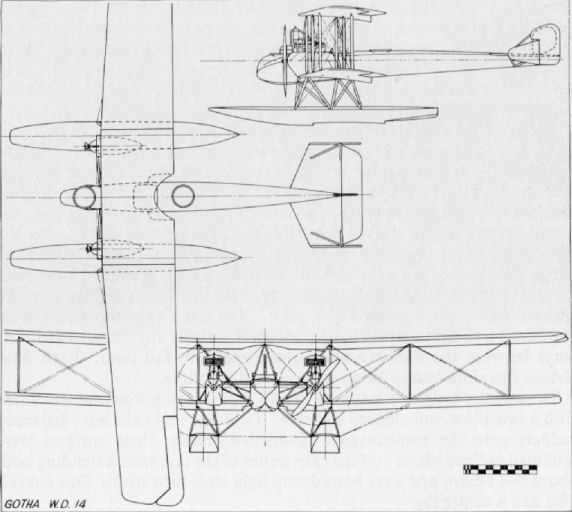
Gotha WD 14
Gotha G IX
The Gotha G IX was not built by the parent firm, but by L.V.G. Little information is available, and it is doubtful if more than one or two machines were built before the war ended. Engines, two 245 h.p. Maybach Mb IV.
Gotha G X
Apart from the fact that it was powered with two 180 h p B M W IIIa engines, no details are available of this small twin-engined machine although it is believed to have been intended as a faster photographic and reconnaissance aircraft.
Gotha G VII (prototype)
During 1918, Gotha developed the twin-engined machine into a smaller, lighter aircraft intended mainly for ultra-long-range photo-reconnaissance duty. Later in the year special units were formed, Reihenbihlzug (Photographic Section), whose establishment consisted of four aircraft. See Gotha G VII (Production) for continuation.
Gotha G VII (production)
As may be seen, the production aircraft bore little resemblance to the prototype G VII. Additional interplane struts were added; there were ailerons at all four wingtips with improved balances; a compound tail nit was incorporated and the wings were slightly swept to compensate the "sawn-off" nose. With the accent on speed, forward armament was deleted, and the consequent shortened nose enabled the engines to be placed closer together, thereby improving asymmetric power characteristics. Engines, two 260 h.p. Mercedes D IVa. Span, 19.27 m. (63 ft. 2 3/4 in.), length. 9.63 m. (31 ft. 7 1/8 in.). Area, 63.8 sq.m. (689 sq.ft.). Weights: Empty, 2,419 kg. (5,322 lb.). Loaded, 3,139 kg. (6,906 lb.). Speed, 180 km.hr. (112.3 m.p.h.). Climb. 6,000 m. (19,680 ft.) in 38 min. Duration. 3 hr. Armament, one Parabellum machine-gun in dorsal position.
Gotha G VIII
Further development of the short-nose twins resulted in the G VIII, which may be seen to resemble the prototype G VII except for the wings of noticeably increased span. A lightened version, designated GL VIII, had a compound tail assembly and auxiliary struts bracing the upper wingtips. Engines, two 245 h.p. Maybach Mb IV. Span, 21.73 m. (71 ft. 3 5/8 in.). Length, 9.79 m. (32 ft. 1 1/2 in.). Height, 3.51 m. (11 ft. 6 1/4 in.). Area, 79 sq.m. (861 sq.ft.). Weights: Empty, 2,676 kg. (5,887 lb.). Loaded, 3,706 kg. (8,153 lb.). Speed, 180 km.hr. (112.5 m.p.h.).

Gotha G VIII
Gotha WD 22
To pursue investigation into long-range reconnaissance and patrol duties, two Gotha WD 22s were built during 1918, Nos. 2133 and 2134. They were powered by four engines tandem mounted in twin nacelles; the forward engines driving tractor airscrews were 160 h.p. Mercedes D IIIs, and the rear engines driving pusher airscrews were 100 h.p. Mercedes D I. They were generally similar to the WD 14s. Span, 26.0 m. (85 ft. 3 3/4 in.) Length, 14.4 m. (47 ft. 3 in.). Area, 147 sq.m. (1,588 sq.ft.). Weights. Empty, 3,800 kg. (8,360 lb.). Loaded, 5,170 kg. (11,374 lb.). Speed. 131 km.hr. (82.19 m.p.h.). Armament, manually operated Parabellum machine-guns fore and aft.
To pursue investigation into long-range reconnaissance and patrol duties, two Gotha WD 22s were built during 1918, Nos. 2133 and 2134. They were powered by four engines tandem mounted in twin nacelles; the forward engines driving tractor airscrews were 160 h.p. Mercedes D IIIs, and the rear engines driving pusher airscrews were 100 h.p. Mercedes D I. They were generally similar to the WD 14s. Span, 26.0 m. (85 ft. 3 3/4 in.) Length, 14.4 m. (47 ft. 3 in.). Area, 147 sq.m. (1,588 sq.ft.). Weights. Empty, 3,800 kg. (8,360 lb.). Loaded, 5,170 kg. (11,374 lb.). Speed. 131 km.hr. (82.19 m.p.h.). Armament, manually operated Parabellum machine-guns fore and aft.
Gotha WD 27
Designed for long-range patrol and bombing duties, three of these colossal machines were built during 1918, Nos. 4326-4328. They truly came into the Rs category (Riesen-Seeflugzeug, Giant Seaplane), and were powered by four 160 h.p. Mercedes D III engines mounted tandem fashion in twin nacelles, driving neatly spinnered tractor and pusher airscrews. Span, 31.0 m. (101 ft. 8 5/8 in.). Length, 17.6 m. (57 ft. 9 in.). Area, 193 sq.m. (2,084 sq.ft.). Weights: Empty, 4,500 kg. (9,900 lb.). Loaded, 6,690 kg. (14,718 lb.). Speed, 135 km.hr. (84.35 m.p.h.).
Designed for long-range patrol and bombing duties, three of these colossal machines were built during 1918, Nos. 4326-4328. They truly came into the Rs category (Riesen-Seeflugzeug, Giant Seaplane), and were powered by four 160 h.p. Mercedes D III engines mounted tandem fashion in twin nacelles, driving neatly spinnered tractor and pusher airscrews. Span, 31.0 m. (101 ft. 8 5/8 in.). Length, 17.6 m. (57 ft. 9 in.). Area, 193 sq.m. (2,084 sq.ft.). Weights: Empty, 4,500 kg. (9,900 lb.). Loaded, 6,690 kg. (14,718 lb.). Speed, 135 km.hr. (84.35 m.p.h.).

Gotha WD 27
Halberstadt B
Other than in its undercarriage, there was little to distinguish the Halberstadt B from its contemporary B types. It is doubtful if more than one or two were built and unlikely that they saw any service other than in a training capacity. Engine, 80 h.p. Oberursel U O.
Other than in its undercarriage, there was little to distinguish the Halberstadt B from its contemporary B types. It is doubtful if more than one or two were built and unlikely that they saw any service other than in a training capacity. Engine, 80 h.p. Oberursel U O.
Halberstadt B I, II and III
In this early 1915 product of the Halberstadt firm may be seen the lines that were to become familiar in their D II to D IV series, which appeared in the opening months of the following year. With a duration of four hours, the B II was a useful reconnaissance aircraft, although the observer, sitting in front, had a poor view. A B III with 120 h.p. Mercedes D II was also built. Engine, 100 h.p. Mercedes D I. Span, 120 m. (39 ft. 4 1/2 in.). Area, 32.0 sq.m. (346 sq.ft.). Weights: Empty, 641 kg. (1,410 lb.), Loaded, 1,047 kg. (2,303 lb.).
Halberstadt C I
This aircraft appears to be a smaller and compact development of the B II with the crew positions reversed and the observer equipped with a defensive machine-gun. The rudder is not braced as formerly, and would appear to have been weak, as bracing struts were revived for the subsequent D types. Engine, unknown, but rotary.

Halberstadt B II
Halberstadt D I
Precursor of the later D II-III series machines, the Halberstadt D I appeared in February 1916. It displayed most of the characteristics perpetuated in the series machines; the delicate, angular, "all-moving" tail surfaces; the two-bay wings; in-line engine. It differed predominantly in having unstaggered wings and the radiators mounted on the fuselage sides. Although not confirmed, dimensional data applicable to D II-III was probably common also to the D I. Engine, 100 h.p. Mercedes D I. Armament, one Spandau machine-gun.
Precursor of the later D II-III series machines, the Halberstadt D I appeared in February 1916. It displayed most of the characteristics perpetuated in the series machines; the delicate, angular, "all-moving" tail surfaces; the two-bay wings; in-line engine. It differed predominantly in having unstaggered wings and the radiators mounted on the fuselage sides. Although not confirmed, dimensional data applicable to D II-III was probably common also to the D I. Engine, 100 h.p. Mercedes D I. Armament, one Spandau machine-gun.
Halberstadt D II and D III
The first single-seat scout product of the Halberstadter Flugzeug-Werke was the 100 h.p. Mercedes-engined D I of late 1915. This was an orthodox slab-sided, two-bay aircraft typical of its period, with a flush-type radiator located in the starboard side of the centre-section panel and a claw brake mounted in the centre of the axle. The D I was subsequently modified by installing a 120 h.p. Argus As II engine which was completely cowled in behind a car-type radiator, with an ungainly exhaust manifold ejecting over the top wing.
In 1916 the aircraft was again re-engined with the 120 h.p. Mercedes D II, and in this form it went into production as the D II to supplement the Fokker D type biplanes, which were then replacing the obsolescent Fokker monoplanes. The Halberstadt D II was a neat little aeroplane and its two-bay wing structure made it exceedingly strong. The fuselage was a normal wooden structure with hollow square-section longerons. The vertical and lateral spacers were kept in place rather ingeniously by small wood blocks tacked to the longerons and the tension of the bracing cables anchored to special angular wiring plates at each corner. At the extreme nose were curved metal panels housing the fore end of the 120 h.p. Mercedes D II. The panels adjacent to the cylinder block - which was left exposed - were also metal. Exhaust systems varied: at first a long exhaust pipe led down the starboard side of the fuselage as far aft as the cockpit; later a chimney-type manifold was fitted, exhausting over the top wing. The curved decking forward of the cockpit and the remainder of the nose was ply covered. Aft of the cockpit was a curved decking built up of formers and light stringers which terminated some distance in advance of the tail, an arrangement that could not have improved the airflow over the control surfaces. To the rear of this decking the fuselage tapered wedge-like to a horizontal knife-edge and, except for the extreme rear panel, which was ply-covered, the rear half of the fuselage was fabric-covered.
There were no fin surfaces in the empennage, which was constructed throughout of light-gauge steel tube. The elevators were of trapezoidal shape, almost identical to those of the contemporary Fokker types. The rudder of approximately triangular profile, was braced by two steel struts, yet it appeared to be a singularly vulnerable structure. Underneath the tail was an inverted steel-tube tripod to which was hinged the wooden tailskid.
The wings, of almost rectangular shape, had a slightly rounded rake to the tips. They were of conventional construction with two I-section spars and built-up ribs with webs and battens. Unusual in German aircraft was the trailing edge, which in this instance was a light wooden member. Ailerons were of steel-tube construction, of constant chord and unbalanced, actuated by a crank in similar fashion to the Albatros scouts. A flush radiator, conforming to the aerofoil section, was fitted in the starboard side of the centre-section. In the opposite side the gravity fuel tank was installed and a deep angular cut-out was made in the centre-section trailing edge. The upper wing was sited close to the fuselage, supported on an inverted pyramid of steel struts at the front spar and an inverted vee at the rear spar. All interplane struts were of steel tube.
A normal vee-type undercarriage chassis with two spreader bars was welded from streamlined steel tube. Short horizontal tubes were welded at the apices of the vees, which also served as anchorages for the elastic-cord shock absorbers.
The Halberstadt D III which followed did not differ radically from the D II. Powered by the Argus As II engine of 120 h.p., it was fitted with a less-cumbersome manifold exhausting sideways to starboard. Ailerons were of increased span, with a considerable area of horn balance at the tips. There was also an alteration to the method of attaching the upper wing, the centre-section struts being vertical instead of meeting on the centre-line. The centre-section cut-out was also revised to a cleaner and near semicircular shape. Apart from these modifications, the D II and D III were virtually identical.
At a later date a 150 h.p. Benz Bz III engine was installed in the D III airframe and two machine-guns were fitted; in this guise the machine was designated D IV, but it cannot be confirmed that many of the type were built. Relatively few D IIs and IIIs were built, though some were constructed under licence by Hannoversche Waggonfabrik. The report of the Inter-Allied Commission after the Armistice recorded that 100 Halberstadt D II and D IIIs were at the Front in January 1917. They were supplied initially to the Kampfeinsitzerkommandos serving with the Fl. Abt. reconnaissance units for protection duties. However, with the formation of the first Jastas in the late summer of 1916 they joined the Fokker D IIIs and D IVs, and some of the first Albatros D Is, to form a motley, composite equipage for these units.
By the end of 1916 the Halberstadt D II and D III had become obsolescent and were largely withdrawn from the Western Front or relegated to quieter sectors. However, while on operations they were able to give a good account of themselves and were certainly respected by their Allied adversaries.
TECHNICAL DATA
Description: Single-seat fighting scout.
Manufacturers: Halberstadter Flugzeug-Werke G.m.b.H. (Halb.).
Sub-contractors: Automobil und Aviatik A.G. (Av.); Hannoversche Waggonfabrik A.G. (Han.).
Power Plant:
One 120 h.p. Mercedes D II 6 cylinder in-line water-cooled engine (D II).
One 120 h.p. Argus As II 6 cylinder in-line water-cooled engine (D III).
Dimensions: Span, 8.8 m. (28 ft. 10 1/2 in.). Length, 7.3 m. (23 ft. 11 1/2 in.). Height, 2.66 m. (8 ft. 9 1/8 in.).
Weights: Empty, 561 kg. (1,234 lb.). Loaded, 771 kg. (1,696 lb.).
Performance: Maximum speed, 145 km.hr. (90 m.p.h.). Initial climb, 1,000 m. (3,280 ft.) in 4 min., 3,000 m. (9,840 ft.) in 15 min. Ceiling, 19,600 ft.
Armament: One fixed Spandau machine-gun forward mounted on port side of fuselage.
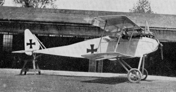
Halberstadt D II of Kampfeinshzer Staffel II.
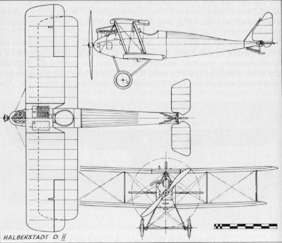
Halberstadt D IV
Penultimate aircraft in the Halberstadt lighter lineage was this D IV of 1917. The neatly spinnered nose and the ply-skinned fuselage shape were characteristics later to be seen in the firm's CL II. The large, balanced ailerons were operated through torque tubes in the upper wing actuated by long external push rods at the centre-section. The neat cowling of the motor is worthy of attention. Engine, 150 h.p. Benz Bz III. Span, 8.8 m. (28 ft. 10 1/2 in.). Length, 7.3 m. (23 ft. 11 1/2 in.). Height, 2.75 m. (9 ft. 0 3/8 in.). Area, 24 sq.m. (259 sq.ft.). Weights: Empty, 525 kg. (1,155 lb.). Loaded, 737 kg. (1,621 lb.). Duration, 1 1/2 hr. Armament, one or two Spandau machine-guns.
Penultimate aircraft in the Halberstadt lighter lineage was this D IV of 1917. The neatly spinnered nose and the ply-skinned fuselage shape were characteristics later to be seen in the firm's CL II. The large, balanced ailerons were operated through torque tubes in the upper wing actuated by long external push rods at the centre-section. The neat cowling of the motor is worthy of attention. Engine, 150 h.p. Benz Bz III. Span, 8.8 m. (28 ft. 10 1/2 in.). Length, 7.3 m. (23 ft. 11 1/2 in.). Height, 2.75 m. (9 ft. 0 3/8 in.). Area, 24 sq.m. (259 sq.ft.). Weights: Empty, 525 kg. (1,155 lb.). Loaded, 737 kg. (1,621 lb.). Duration, 1 1/2 hr. Armament, one or two Spandau machine-guns.
Halberstadt G I
Constructed during the winter of 1915/16, Halberstadt's G I was their sole entry into the twin-engine field. So far as is known only one machine was built. Engines, two 160 h.p. Mercedes D III. Span, 15.5 m.(50 ft. 10 3/8 in.). Length, 9.0 m. (29 ft. 6 3/8 in.). Height, 3.2 m. (10 ft. 6 in.). Weights: Empty, 1,220 kg. (2,684 lb.). Loaded, 1,895 kg. (4,169 lb.). Speed. 152 km.hr. (95 m.p.h.). Climb, 1,000 m. (3,280 ft.) in 7 min. Duration. 4 hr. Armament, one or two Parabellum machine-guns; 200 kg. (440 lb.) bomb load.
Constructed during the winter of 1915/16, Halberstadt's G I was their sole entry into the twin-engine field. So far as is known only one machine was built. Engines, two 160 h.p. Mercedes D III. Span, 15.5 m.(50 ft. 10 3/8 in.). Length, 9.0 m. (29 ft. 6 3/8 in.). Height, 3.2 m. (10 ft. 6 in.). Weights: Empty, 1,220 kg. (2,684 lb.). Loaded, 1,895 kg. (4,169 lb.). Speed. 152 km.hr. (95 m.p.h.). Climb, 1,000 m. (3,280 ft.) in 7 min. Duration. 4 hr. Armament, one or two Parabellum machine-guns; 200 kg. (440 lb.) bomb load.

Halberstadt G I
Halberstadt C III
Built towards the end of 1917, the C III was the first of the Halberstadt standard two-seaters intended for long-range reconnaissance, and formed the basis of the later C V, which was to see series production. It was a conventional machine of wood and fabric with ply-skinned fuselage; its only singular feature was the mounting of the lower wing on a keel to afford an increased gap. According to Idflieg report, six machines were completed. Engine, 200 h.p. Benz Bz IV. Span, 12.2 m. (40 ft. 0 3/8 in.) length, 7.7 m. (25 ft. 3 1/4 in.). Height, 2.95 m. (9 ft. 8 1/8 in.). Weights: Empty. 850 kg. (1.870 lb.). Loaded, 1.310 kg. (2,882 lb.). Speed, ca. 165 km.hr. (103.125 m.p.h.). Armament, one Parabellum and one Spandau machine-gun.
Built towards the end of 1917, the C III was the first of the Halberstadt standard two-seaters intended for long-range reconnaissance, and formed the basis of the later C V, which was to see series production. It was a conventional machine of wood and fabric with ply-skinned fuselage; its only singular feature was the mounting of the lower wing on a keel to afford an increased gap. According to Idflieg report, six machines were completed. Engine, 200 h.p. Benz Bz IV. Span, 12.2 m. (40 ft. 0 3/8 in.) length, 7.7 m. (25 ft. 3 1/4 in.). Height, 2.95 m. (9 ft. 8 1/8 in.). Weights: Empty. 850 kg. (1.870 lb.). Loaded, 1.310 kg. (2,882 lb.). Speed, ca. 165 km.hr. (103.125 m.p.h.). Armament, one Parabellum and one Spandau machine-gun.

Halberstadt C III
Halberstadt CL II
Designed to the new CL (Light C type) specification in 1917, to equip the Schutzstaffeln (Protection Flights), the Halberstadt CL II was built in considerable numbers. Coming into use in the summer of 1917, it was later reinforced by the Hannover CL types, and used mainly as a two seat fighter to escort C type reconnaissance and photographic patrol machines. However, the German High Command had by this time come to appreciate the importance and morale effect of close-support aircraft operating with infantry attacks, and the designation of the Schutzstaffeln was later changed to Schlachtstaffeln (Battle Flights), and the duties accordingly varied to close-support and ground attack When not required to support a specific ground operation the Schlastas resumed their former escort role and chaperoned their C-type comrades.
The Halberstadt CL II, with its distinctive communal single cockpit occupied by both pilot and observer (in similar fashion to the British Bristol Fighter), facilitated improved co-operation between the crew and was admirably suited to its new found close-support fighting role. With the advent of these faster and more nimble light two-seaters the degree of cooperation with the infantry was highly co-ordinated, and from late summer of 1917 a considerable degree of success was achieved. This is evidenced by the fact that the British convened a Court of Inquiry in January 1918 to examine the cause of success of the German counter-offensive of 30th November 1917 during the Battle of Cambrai. The findings recorded the appearance of the close-support aircraft in considerable numbers at altitudes lower than 100 ft., firing into both the Front-Line trenches and the rear positions. The morale effect was reported as being very great and facilitated the German success, British infantry seeming at a loss to counteract the effect of these low-flying machines. One witness stated that firing on them produced no visible effect.
In addition to the machine-gun armament, Halberstadt CL IIs had trays fitted to the outside of the fuselage in which anti-personnel grenades were carried. These were dropped overboard by the observer into trenches and on targets of opportunity.
One of the first successful operations involving the Halberstadt CL II was an attack on the Somme bridges at Bray and St. Christ on 6th September 1917. The Germans had been obliged to evacuate Peronne due to the success of heavy attacks by the British, and the concentration of British reserves on the west bank of the river had been spotted by reconnaissance aircraft. It was planned to attack these troops as they actually crossed the bridges, where it was estimated the greatest havoc might be wrought. Such indeed was the case - the attack was mounted by twenty-four Halberstadts and panic ensued, troops jumping over the parapets of the two bridges in their endeavour to escape the machine-gun fire and grenades coming from the enemy aircraft. The artillery troops and their horses farther in the rear were also attacked, and it was estimated the Halberstadts had disorganized the best part of a division. During the whole period the Halberstadts were assailed by only two Sopwith scouts, one of which was promptly shot down, the other then making off.
Although lightly built, the Halberstadt CL II was a quite strong machine by virtue of its compactness. It was a small aircraft for a two-seater, and its single-bay configuration resulted in neat and elegant proportions. Power was supplied by the ubiquitous 160 h.p. Mercedes D III, and a neatly spinnered propeller imparted a streamlined nose-entry, only the fore part of the cylinder block being exposed above the metal nose-cowling panels. The remainder of the fuselage was a wooden structure covered with thin plywood panelling and tapered to a horizontal knife-edge aft. The fixed tail surfaces, with the vertical fin distinctively mounted well ahead of the tailplane, were of wooden framing, while the one-piece elevator and large balanced rudder were welded steel-tube units, the whole being fabric covered.
In the single-bay wings the upper had a pronounced sweep which, combined with the dihedral in the lower wing only, gave the aircraft a somewhat rakish appearance. Of orthodox wooden construction, based on two spruce main spars and with plywood leading-edges, the wings were fabric covered and mounted at a considerable angle of incidence. On the lower wings this incidence was washed out at the inboard ends to provide a better join with the fuselage and to improve the airflow. The large, fabric-covered, horn-balance ailerons were of typical German design in appearance, but their method of operation was different. Of welded steel-tube framing, they were positively actuated by push-rods connected to cranks mounted on the inboard ends of torque tubes which extended through the wings to the centre-section. The centre-section panel of the upper wing was supported on a rigid system of steel-tube struts which were not cable-braced in any way, and its close proximity to the fuselage afforded the pilot first-class upward and forward vision. Also, in conjunction with his elevated gun-ring, the observer was able to fire upward and forward. The aerofoil-shaped radiator was installed flush in the starboard side of this centre-section panel and the gravity fuel tank was in the port side. Interplane struts were of streamlined section steel tube, and bracing was of steel cable.
The conventional undercarriage had steel-tube vees, a single spreader bar and the axle sprung with multiple spiral springs. The large ash tailskid was hinged immediately under the rudder post and internally sprung.
TECHNICAL DATA
Description: Light two-seat C type, escort and ground attack.
Manufacturers: Halberstadter Flugzeug-Werke G.m.b.H. (Halb.).
Sub-contractor: Bayerische Flugzeug-Werke A.G.
Power Plant: One 160 h.p. Mercedes D III 6 cylinder in-line water-cooled engine.
Dimensions: Span, 10.77 m. (35 ft. 4 in.). Length, 7.3 m. (23 ft. 11 3/8 in.). Height, 2.75 m. (9 ft. 0 1/4 in.). Area, 27.5 sq.m. (297 sq.ft.).
Weights:
Empty, 773 kg. (1,701 lb.). Loaded, 1,133 kg. (2,493 lb.). (Official figures.)
Empty, 796 kg. (1,751 lb.). Loaded, 1,166 kg. (2,565 lb.). (Figures painted on some aircraft.)
Performance: Speed, 165 km.hr. (103.12 m.p.h.) at 5,000 m. (16,400 ft.). Climb, 1,000 m. (3,280 ft.) in 5 min., 5,000 m. (16,400 ft.) in 39.5 min. Ceiling, 16,700 ft. Duration, 3 hr.
Armament: One or two fixed Spandau machine-guns (according to duties) forward and one manually operated Parabellum machine-gun in rear cockpit. Anti-personnel grenades. Four or five 10 kg. (22 lb.) bombs.
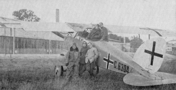
Halberstadt CL II (serial C 6304/17).
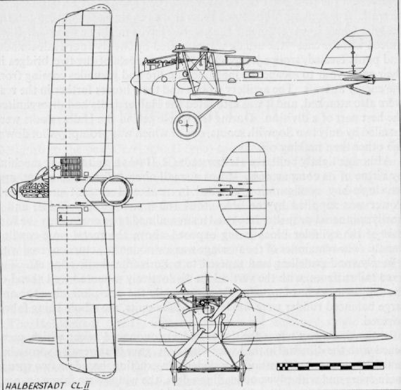
Halberstadt D V
Virtually a standard D III airframe fitted with either Mercedes or Argus engine, and with modified centre-section struts and ailerons. The D V was reputedly delightful to fly. As may be seen from the national insignia of the aircraft illustrated, some examples were supplied to the Turkish Government. Engine, 120 h.p. Mercedes D II or Argus D II. Span. 8.8 in (28 ft. 10 1/2 in.). Length, 7.3 m. (23 ft. 11 1/2 in.). Climb, ca. 1,000 m. (3,280 ft.) in 3 min.
Virtually a standard D III airframe fitted with either Mercedes or Argus engine, and with modified centre-section struts and ailerons. The D V was reputedly delightful to fly. As may be seen from the national insignia of the aircraft illustrated, some examples were supplied to the Turkish Government. Engine, 120 h.p. Mercedes D II or Argus D II. Span. 8.8 in (28 ft. 10 1/2 in.). Length, 7.3 m. (23 ft. 11 1/2 in.). Climb, ca. 1,000 m. (3,280 ft.) in 3 min.
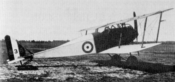
Halberstadt D III captured by the R.F.C. and given British roundels.

Halberstadt D III.
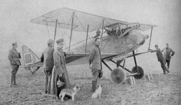
Halberstadt D V
Halberstadt C V
With the implementation of the "America Programme" during the final year of the war and the consequent expansion of most of the German flying units, the Halberstadt C V was scheduled to supplement the photographic Fl. Abt. Unaccountably this type appears to have been overlooked by historians in the past, even though it was produced in considerable numbers and built under licence by at least three sub-contractors.
Designed for high-altitude, long-distance (Fernerkunder) reconnaissance and photographic work, the C V initially appeared in the early months of 1918. It was extensively tested, and one airframe, 1246/18, was critically assessed and finally tested to destruction over the period 26th March to 22nd April 1918, at Adlershof. However, it was mid-summer before the type became operational.
The high-aspect-ratio wings were of considerable span for a two-seater, and contributed to increased efficiency at altitude. The high-compression 220 h.p. Benz Bz IV engine also improved altitude performance.
Superficially, the fuselage and tail surfaces resembled those of the CL IV, but were proportionately larger, and the communal cockpit was abandoned for the more conventional arrangement. Installation of the 220 h.p. Benz motor was similar to the CL IV, with bulbous metal panels at the front and metal panels adjacent to the cylinder block, the fore part of which protruded. The chimney-type manifold exhausted over the upper wing. The remainder of the fuselage was of wooden construction, with slab sides and a rounded top decking which tapered to a horizontal knife-edge aft; it was covered with a thin plywood skin. A sliding "trap door" located in the floor of the rear cockpit moved laterally to allow the camera lens to be exposed when "shooting" was in progress. Fin and tailplane, which was attached direct to upper longerons, were of wooden construction with fabric covering; the balanced rudder and one-piece balanced elevator were of light-gauge steel tube, and likewise fabric covered.
The two-bay high-aspect-ratio wings were of uniform chord, fabric covered and based on two spruce main spars. The front spar was of I-section reinforced with 2 mm. ply between the flanges. The rear spar was a more orthodox hollow box-spar faced with 1.5 mm. ply. The leading edge was a channelled wooden member, and the trailing edge was a light wooden slat. Some of the earlier models had both upper and lower wingtips raked and the aileron balances inset, but in the main production variant only the upper wingtips were raked and the large, horn-balanced ailerons were overhung. Their framework was of steel tubes and actuation was through torque tubes, again in similar manner to the CL types. Supported on splayed steel-tube "N" struts, the wide centre-section of the upper wing had a large V-shaped cut-out to improve the pilot's upward vision: the flush radiator and gravity fuel tank were mounted in the starboard and port sides respectively. In the lower wings the tips were rounded with a compound elliptical profile (reminiscent of the D.F.W. C V), and the roots again featured the characteristic washout to smooth the airflow.
The undercarriage was of conventional vee-type chassis of streamlined steel tube with two spreader bars, sprung with multiple steel springs. The ash tailskid was mounted and hinged to a small under-fin as on the CL IV.
Together with their Rumpler C VII contemporaries, the Halberstadt C Vs performed yeoman service in providing photographic intelligence during the final months of the war. They were obliged to operate under the inordinately difficult conditions of frequent retreat, and in the face of continually increasing Allied fighter opposition.
TECHNICAL DATA
Description: Two-seat photographic reconnaissance.
Manufacturers: Halberstadter Flugzeug-Werke G.m.b.H. (Halb.).
Sub-contractors: Automobil und Aviatik A.G. (Av.); Bayerische Flugzeug-Werke A.G. (Bay.); Deutsche Flugzeug-Werke G.m.b.H. (Dfw.).
Power Plant: One 220 h.p. Benz Bz IV 6 cylinder in-line water-cooled engine fitted with high-compression cylinders.
Dimensions: Span, 13.62 m. (44 ft. 8 3/4 in.). Length, 6.92 m. (22 ft. 8 1/2 in.). Height, 3.36 m. (11 ft. 0 1/4 in.). Area, 43 sq.m. (464.4 sq.ft.).
Weights: Empty, 930 kg. (2,046 lb.). Loaded, 1,365 kg. (2,730 lb.).
Performance: Maximum speed, 170 km.hr. (106.25 m,p.h.). Initial climb, 2,000 m. (6,560 ft.) in 3.2 min.; 5,000 m. (16,400 ft.) in 23 min. Duration, 3 1/2 hr.
Armament: One fixed Spandau machine-gun mounted to port forward and one manually operated Parabellum machine-gun in rear cockpit.
Halberstadt C IX
The C IX was, in effect, yet another C V variant; it was the same airframe with the Austrian 230 h.p. Hiero engine installed. Doubtless it was the intention to supply such machines for use by the Austro-Hungarian Air Force, but it seems unlikely any were delivered. Engine, 230 h.p. Hiero. Data, as for C V. Weights: Empty, 950 kg. (2,090 lb.). Loaded, 1,380 kg. (3.036 lb.). Armament, one Parabellum and one Spandau machine-gun.
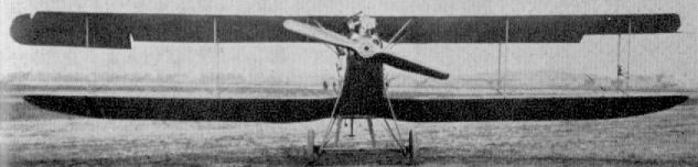
Halberstadt C VII (???)
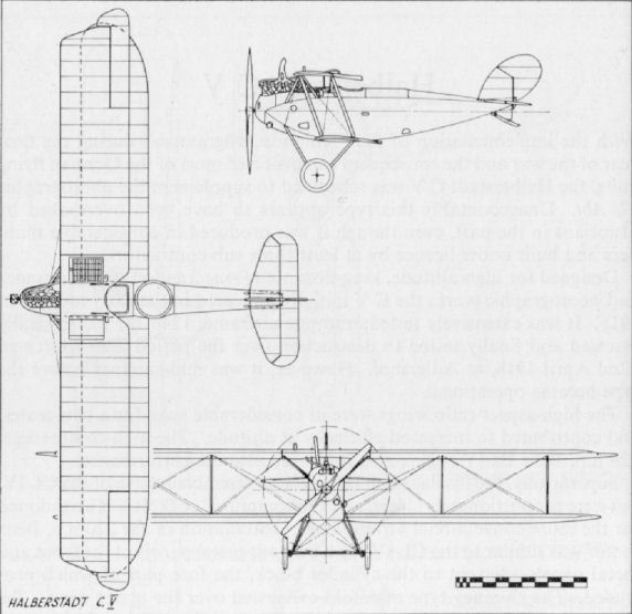
Halberstadt C VII
This aircraft, produced late in 1918, was little more than a standard Halberstadt C V airframe fitted with a 245 h.p. Maybach Mb IV engine. It remained only a prototype, probably a test bed for the subsequent C VIII. Armament, one Parabellum and one Spandau machine-gun.
Halberstadt C VIII
Appearing in the summer of 1918, the C VIII would in all probability have followed the C V into production but for the cessation of hostilities. As it was, only one was built. This machine was type tested on 2nd October 1918. It was a large aircraft for a single-bay layout, and seems to have utilised much of the CL IV tail design. Engine, 245 h.p. Maybach Mb IV. Span, 11.985 m. (39 ft. 4 in.). Length, 7.35 m. (24 ft. 1 3/8 in.). Height, 2.95 m. (9 ft. 8 1/8 in.). Area, 33 sq.m. (356 sq.ft.). Weights: Empty, 928 kg. (2,042 lb.). Loaded, 1.363 kg. (2,999 lb.). Speed, 180 km.hr. (112.5 m.p.h.). Climb, 5,000 m. (16,400 ft.) in 21 min. To ceiling 9,000 m. (29,520 ft.) in 58 min. Duration, 34 hr. Armament, one Parabellum and one Spandau machine-gun.
Halberstadt CL IV
The Halberstadt CL IV was introduced with the vast expansion of the Schlachtstaffeln for the March 1918 offensive to supplement - and eventually supersede - the Halberstadt CL II.
By this period the Schlastas had become highly organised formations and operated with devastating effect in close support of their own infantry or in breaking up Allied counter-attacks. The effective fighting strength of a Schlasta had not to be less than four aircraft; the actual establishment was six. This number was found to be the maximum for efficient command - or co-ordination - once airborne. They were intended for use only at decisive points of attack, and not squandered singly over the whole front of an attack. Less-important sectors had to dispense with their services. Utmost precision in the time of their attack was necessary. To arrive too soon would draw enemy attention prematurely to the point of the attack; if too late they became a danger to their own advancing troops. Consequently, highly detailed and precise orders were compiled by the German Staff. In attack the prior objective of the "Battle Flights" was to fly ahead of the infantry, straffing, and to keep down the fire of the enemy's infantry and their artillery batteries. Each flight was given a specific target, and there were orders not to abandon this for a more favourable one.
In defence, as soon as the enemy's preparations indicated an imminent offensive, the Schlastas were ordered in to relentlessly attack and disorganize assembly points in an endeavour to delay or break up the attack. As the infantry battle swayed to and fro the "Battle Flights" were held in readiness until local reserves could be mustered to mount an organised counterattack, to which the air support could be added.
During the final German onslaught of March 1918 no less than thirty eight Schlachtstaffeln had been formed and were largely equipped with Halberstadt CL II and CL IV aircraft, supplemented by Hannover CL IIIa units. Some twenty-seven of these units were opposed to the British forces.
Although intended as a replacement for the CL II, the Halberstadt CL IV was not unlike its predecessor in concept, and did not offer much improvement in performance other than in manoeuvrability, which, for the duties required, was a prerequisite quality. The same 160 h.p. Mercedes D III power plant was retained, although the airscrew spinner was omitted, and modified bulbous panels encowled the nose, imparting a more aggressive appearance. As before, the wooden fuselage was ply-skinned and still incorporated the communal cockpit with an elevated gun ring for the observer.
Horizontal tail surfaces were considerably redesigned, being of greater span and higher aspect ratio than in the CL II. The one-piece elevator was horn balanced, which, together with the shorter fuselage, afforded a much greater degree of fore-and-aft sensitivity and all-round improvement in manoeuvrability.
The wings were of normal wooden construction as in the CL II, but due to the fuselage being some 3 ft. shorter, it was necessary for them to be repositioned to ensure location of the centre of gravity around the crew compartment. Particular attention was paid to the lower wing/fuselage junction to ensure a smoother airflow over the tail surfaces. No actual fairing was used, but the wing root was washed out, and to achieve this the rear spar had to be both bent and twisted. The upper wing was largely the same as on the earlier machine, with swept outer panels; radiator and gravity fuel tank were located in the starboard and port sides of the centre-section, respectively. The large balanced ailerons were retained at the upper wingtips, operated through torque tubes as before.
Steel-tube vees of streamline section, with two spreader bars, were employed in the undercarriage chassis and the axle sprung with multiple steel springs. The ash tailskid was hinged to a small underfin, which was added to increase directional stability.
Provision was made for the mounting of two fixed forward-firing machine-guns, but only one was usually fitted. Anti-personnel grenades in shallow boxes were carried on the fuselage sides, and rows of Very cartridges were often strapped across the rear fuselage decking.
After the failure of the 1918 offensive when the Allies began to counterattack, the Schlastas came to be used more and more in defensive support of their own infantry instead of in their intended offensive role. Life was indeed very hectic and uncertain in these units and, not being armoured, they had only their manoeuvrability to avoid the small-arms fire to which they were increasingly exposed and to which they so often became victims.
When not on close-support duties they were used as ordinary two-seat fighters on escort work, and were able to give an extremely good account of themselves when attacked by Allied aircraft. They also found employment towards the end of the war on bright moonlight nights when they attempted to intercept and destroy Allied bombing machines as they returned from their missions. Night sorties against Allied billets and aerodromes were also made. Although these lacked the decisiveness of the daylight attacks, they had a considerable nuisance value and caused many casualties.
TECHNICAL DATA
Description: Light two-seat C type, ground attack and escort.
Manufacturers: Halberstadter Flugzeug-Werke G.m.b.H. (Halb.).
Sub-contractor: Luftfahrzeug Gesellschaft m.b.H. (Rol.).
Power Plant: One 160 h.p. Mercedes D III 6 cylinder in-line water-cooled engine.
Dimensions: Span, 10.742 m. (35 ft. 2 7/8 in.). Length, 6.538 m. (21 ft. 5 1/2 in.). Height, 2.67 m. (8 ft. 9 1/8 in.). Area, 27 sq.m. (297 sq.ft.).
Weights: Empty, 728 kg. (1,602 lb.). Loaded, 1,068 kg. (2,349.6 lb.).
Performance: Maximum speed, 165 km.hr. (103.12 m.p.h.). Climb, 5,000 m. (16,400 ft.) in 32 min. Duration, 3-3 1/2 hr.
Armament: One or two fixed Spandau machine-guns forward and one manually operated Parabellum machine-gun in rear cockpit. Anti-personnel grenades and four or five 10 kg. (22 lb.) bombs.
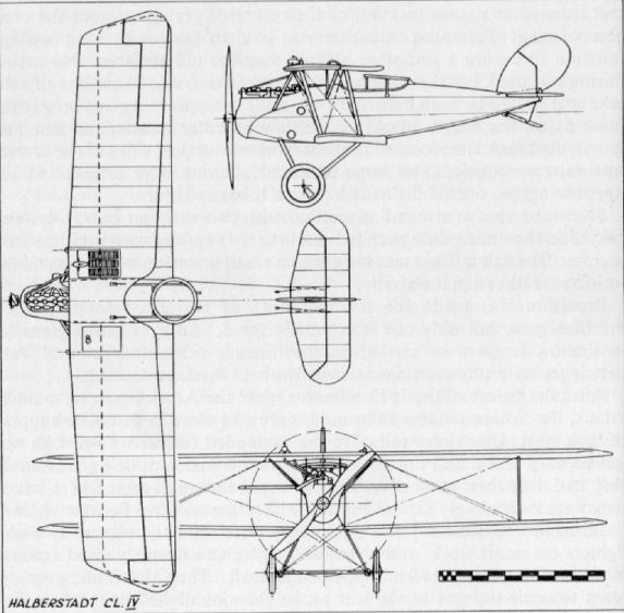
Halberstadt CLS I
Designed to succeed the CL II and CL IV types, the CLS I was even smaller and lighter, and it was also faster. Type tested on 2nd October 1918, it came too late to go into production. But for the absence of curvature in the lower wing roots and the built-up rear cockpit, the CLS I might be confused with the CL IV: construction was almost identical. Further development in the shape of CLS II and CLS X, with 3.5 cm. revolver cannon, remained no more than projects. Engine, 160 h.p. Mercedes D III. Span, 9.7 m. (31 ft. 9 7/8 in.). Length, 6.95 m. (22 ft. 9 5/8 in.). Height, 3.05 m. (10 ft. 0 1/8 in.). Area, 26.4 sq.m. (285 sq.ft.). Weights: Empty, 682 kg. (1,500 lb.). Loaded, 1,102 kg. (2,424 lb.). Speed, 185 km.hr. (115.625 m.p.h.). Climb, 4,500 m. (14,760 ft.) in 36 min. Armament, one Parabellum and two Spandau machine-guns.
Designed to succeed the CL II and CL IV types, the CLS I was even smaller and lighter, and it was also faster. Type tested on 2nd October 1918, it came too late to go into production. But for the absence of curvature in the lower wing roots and the built-up rear cockpit, the CLS I might be confused with the CL IV: construction was almost identical. Further development in the shape of CLS II and CLS X, with 3.5 cm. revolver cannon, remained no more than projects. Engine, 160 h.p. Mercedes D III. Span, 9.7 m. (31 ft. 9 7/8 in.). Length, 6.95 m. (22 ft. 9 5/8 in.). Height, 3.05 m. (10 ft. 0 1/8 in.). Area, 26.4 sq.m. (285 sq.ft.). Weights: Empty, 682 kg. (1,500 lb.). Loaded, 1,102 kg. (2,424 lb.). Speed, 185 km.hr. (115.625 m.p.h.). Climb, 4,500 m. (14,760 ft.) in 36 min. Armament, one Parabellum and two Spandau machine-guns.

Halberstadt CLS I
Hannover CL II, III and IIIa
Hannoversche Waggonfabrik A.G. had long been famous as railway-rolling-stock constructors when in 1915 they were required by the German Government to undertake the construction of aeroplanes. When the aircraft branch was eventually established at Hannover-Linden the first types to be built under licence were the Aviatik C I, Rumpler C Ia and Halberstadt D II. As the production of aircraft got into its stride during 1916, so the drawing office, under the guidance of Hermann Dorner (who was one of the pioneers of German aviation), gave thought to a machine of their own. During 1917 the Flugmeisterei had issued a specification calling for a lighter type of C class two-seater, to be powered by a 160-180 h.p. engine and classified in the new CL category. Instead of the reconnaissance, photographic and artillery-observation duties performed by the standard C types, the CL machines were to act more as two-seat fighters, to be deployed as offensively as possible and to act as escort (Schutzstaffeln) to the C class machines. Later the Schutzstaffeln were redesignated Schlachtstaffeln (Battle Flights) and additionally used to co-operate with the ground troops in low-level straffing and harassing of the opposing infantry lines and rear areas.
To fulfil this specification Dorner produced the Hannover CL II (there was no CL I; having already built Av C I, the next numeral was simply allotted to the CL category) powered with an Argus As III engine of 180 h.p., and developed it, with little modification, into CL III and IIIa. The main difference in the types was in the type of engine and in the wingtips. The prototype CL II had uniform dihedral of 2° in both wings, and the upper tailplane was of angular outline. In the production aircraft the dihedral was differential, and the upper tailplane of familiar (approximately semicircular) shape was standardised. The wingtips had a plainly raked tip and the ailerons were not overhung as in later models.
Modification of the wingtips, together with ailerons incorporating overhung balances, was introduced in the CL III, which also differed in mounting a 160 h.p. Mercedes D III motor. However, as these Mercedes motors were required more urgently for the single-seat fighters, the CL III reverted to the 180 h.p. Argus As III. In this guise the machine was known as the CL IIIa, and this variant saw the greatest quantity production.
The Hannover, as a single-engined aircraft, was unique in having a biplane tail. Such a feature had previously been seen only on multi-engined aircraft. Its purpose was to reduce the tailplane/elevator span, thereby affording a wider field of fire for the observer, an object which was achieved in no small measure. For a two-seater the CL IIIa was a smallish (under 40 ft. span) and compact single-bay aircraft, and was often attacked by Allied scouts in mistake for a single-seater, whereupon they were speedily disabused of their illusion by the hail of fire from the observer's Parabellum machine-gun. Due to the positioning of the upper wing so close to the fuselage, the pilot had an excellent upward field of vision, and the much narrower chord of the lower wing, together with the nature of the stagger, afforded good downward and forward visibility. The compactness of the aeroplane gave excellent manoeuvrability, and it had particularly good lateral control due to the large balanced ailerons.
The fuselage was built on a basic structure of four main longerons with ply formers; forward the section was rectangular, except for the rounded decking; aft of the cockpits the section was developed into a more oval shape. Covering of the fuselage was thin ply sheet covered with doped fabric. Removable panels adjacent to the engine were metal, as was the extreme nose cowling. The deep, roomy fuselage tapered to a vertical knife-edge aft, where the vertical fin was built integral with the structure and was likewise ply and fabric skinned; the lower, deeply cambered tailplane was also similarly covered. The flat-plate section upper tailplane and both sets of elevators were of steel-tube framing and fabric covered; the elevators were connected by a link strut inside the fin and operated by a crank attached to the lower set. Some of the earlier aeroplanes had the two tailplanes connected with a vertical bracing strut, but later the structure was internally strengthened and these struts deleted.
The wings were of conventional wooden construction, based on two box-spars, and had a small degree of sweep, some 1.5°. The lower wings had a pleasantly rounded tip profile, which doubtless contributed to the excellent lateral control. The ailerons were, like the elevators and rudder, of steel-tube framework and fabric covered. All bracing wires were of stranded cables.
Both undercarriage vee struts and interplane struts were of plain circular steel tube with wooden fairings taped on to strengthen and produce a streamlined section. The wheels were sprung with triple coil springs, and the ash tailskid was fastened to the small underfin and sprung with elastic cord.
Hannoveranas - as they were dubbed by the R.F.C. - came into operational use towards the end of 1917, and were, without doubt, formidable opponents. As was the case with most aircraft with ply-covered fuselages, they were immensely strong and could take considerable punishment. In his biography Flying Fury Major J. B. McCudden, V.C., D.S.O., M.C., M.M., wrote:
"I went down to engage him and found that he was a Hannover, a machine which has a biplane tail, and although I fired a lot at him at close range, it had no other effect than to make him dive away, which made me think that perhaps they were armoured. These machines are very deceptive, and pilots are apt to mistake them for Albatros scouts until they get to close range, when up pops the Hun gunner from inside his office."
This was on 1st January 1918; on 26th February 1918 he again reported:
"Then I flew up north, and very soon encountered two Hannovers, whom I fought for some time, but I finally had to leave them, for they were co-operating very well and had started to shoot me about."
Johann Baur, who later in life became personal pilot to Hitler, flew Hannovers for a time and claimed for himself nine victories.
Over a thousand Hannover two-seaters were built for the German Air Force. Of this total, 439 were CL IIs , 80 CL IIIs and 537 IIIas.
TECHNICAL DATA
Description: Light two-seat C type, escort and close support.
Manufacturers: Hannoversche Waggonfabrik A.G. (Han.).
Sub-contractor: Luftfahrzeug Gesellschaft m.b.H. (Rol.). (These aircraft were designated CL IIa.)
Power Plant: One 180 h.p. Argus As III 6 cylinder in-line water-cooled engine (CL III with 160 h.p. Mercedes D III.)
Dimensions: Span, 117m. (38 ft. 4 3/4 in.). Length, 7.58 m. (24 ft. 10 1/2 in.). Height 2.8 m. (9 ft. 2 1/4 in.). Area, 32.7 sq.m. (353 sq.ft.).
Weights: Empty, 717kg. (1,577 lb.); captured aircraft, 1,732 lb. Loaded, 1,081 kg. (2,378 lb.); captured aircraft, 2,572 lb.
Performance: Maximum speed, 165 km.hr. (103.12 m.p.h.) at 5,000 m. (16,400 ft.). Climb, 1,000 m. (3,280 ft.) in 5.3 min. Ceiling, 24,600 ft. Duration, 3 hr.
Armament: One fixed Spandau machine-gun forward and one manually operated Parabellum machine-gun in rear cockpit.
N.B. An example powered with 190 h.p. N.A.G. motor was designated CL IIIb, and an experimental two-bay version was designated CL IIIe.
Hannover CL IIIb
Variant of standard CL IIIa airframe with extended wings of two-bay format. No data as to actual span available. So far as is known, only the single prototype was constructed.
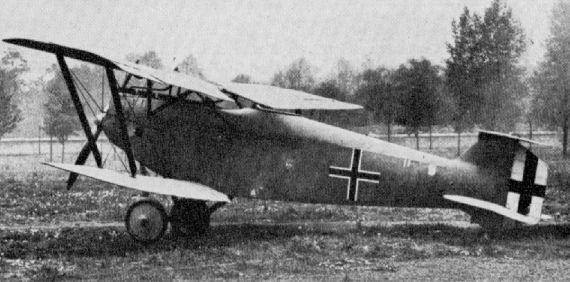
Hannover CL IIIa (serial 7028/18).
The Hannover CL IIIa of 1918 was a relatively minor development of the company's CL II and both used the same 180hp Argus As III. Both the CL II and III series of ground attack and escort fighters endeared themselves to their crews thanks to a number of useful attributes. From the pilot's viewpoint, visibility was excellent both forward and downward, while the quaint biplane tail, with its narrow span and position, provided the observer with an improved rearward arc of fire. Top level speed of the CL IIIa was 103mph at sea level, while the machine had a range of 285 miles. Agile and robust, the first of 439 CL IIs entered service in December 1917, followed by 80 CL IIIs and 537 CL IIIas. Incidentally, the reason for the small number of CL IIIs produced had nothing to do with the aircraft, but rather it was because it used a 160hp Mercedes D III, which was urgently needed to power the Fokker D VII. The standard two-gun armament, one for each crew member, was fitted.
The Hannover CL IIIa of 1918 was a relatively minor development of the company's CL II and both used the same 180hp Argus As III. Both the CL II and III series of ground attack and escort fighters endeared themselves to their crews thanks to a number of useful attributes. From the pilot's viewpoint, visibility was excellent both forward and downward, while the quaint biplane tail, with its narrow span and position, provided the observer with an improved rearward arc of fire. Top level speed of the CL IIIa was 103mph at sea level, while the machine had a range of 285 miles. Agile and robust, the first of 439 CL IIs entered service in December 1917, followed by 80 CL IIIs and 537 CL IIIas. Incidentally, the reason for the small number of CL IIIs produced had nothing to do with the aircraft, but rather it was because it used a 160hp Mercedes D III, which was urgently needed to power the Fokker D VII. The standard two-gun armament, one for each crew member, was fitted.
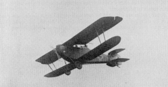
An unusual study of a Hannover CL III returning from a sortie over the lines.
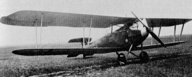
Hannover CL IIIb
Hannover CL.IIIc (1917)
Hannover CL.IIIc (1917)
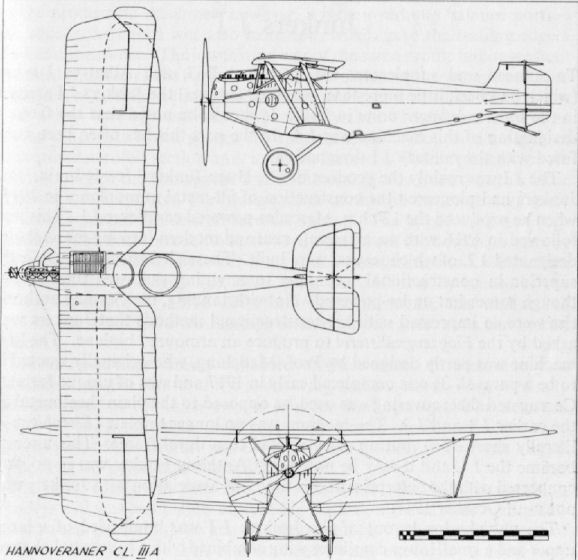
Hannover C IV
Completed early in 1918, the C IV was Hannover's first standard two-seater design. It utilised the 245 h.p. Maybach engine to achieve high-altitude performance, but as this aircraft was no improvement on the Rumpler, it did not go into production. Although fuselage construction was similar to that of the earlier CL series, the singular "I" style interplane and centre-section strut arrangement is of interest. Possibly two prototypes were constructed. The straight-edged patee crosses with their unusually wide outline, on the machine illustrated, were unique. Engine: 245 h.p. Maybach Mb IV. Span, 12.56 m. (41 ft. 2 1/2 in.). Length, 7.8 (25 ft. 7 1/8 in.). Area, 33.6 sq.m. (363 sq.ft.). Weights: Empty, 960 kg. (2,112 lb.). Loaded, 1,395 kg. (3,069 lb.). Speed, 160 km.hr. (100 m.p.h.) at 2,000 m. (6,560 ft.). Climb, 1,000 m. (3,280 ft.) in 4.5 min. Ceiling 9,000 m. (29,520 ft.). Duration, 3 hr. Armament, one Parabellum and one Spandau machine-gun.
Completed early in 1918, the C IV was Hannover's first standard two-seater design. It utilised the 245 h.p. Maybach engine to achieve high-altitude performance, but as this aircraft was no improvement on the Rumpler, it did not go into production. Although fuselage construction was similar to that of the earlier CL series, the singular "I" style interplane and centre-section strut arrangement is of interest. Possibly two prototypes were constructed. The straight-edged patee crosses with their unusually wide outline, on the machine illustrated, were unique. Engine: 245 h.p. Maybach Mb IV. Span, 12.56 m. (41 ft. 2 1/2 in.). Length, 7.8 (25 ft. 7 1/8 in.). Area, 33.6 sq.m. (363 sq.ft.). Weights: Empty, 960 kg. (2,112 lb.). Loaded, 1,395 kg. (3,069 lb.). Speed, 160 km.hr. (100 m.p.h.) at 2,000 m. (6,560 ft.). Climb, 1,000 m. (3,280 ft.) in 4.5 min. Ceiling 9,000 m. (29,520 ft.). Duration, 3 hr. Armament, one Parabellum and one Spandau machine-gun.
Hannover CL V
Hawa produced the CL V late in 1918 in two variants: the first with the characteristic biplane tail and the second with an orthodox empennage. Some fifty airframes were thought to have been completed by the Armistice. Engine, 185 h.p. B.M.W. IIIa. Span, 10.56 m. (34 ft. 7 3/4 in.), biplane tail; 10.49 m. (34 ft. 5 in.), mono tail. Length, 7.1 m. (23 ft. 3 5/8 in.), height, 2.9 m. (9 ft. 6 1/4 in.). Area, 28.5 sq.m. (308 sq.ft.). Weights: Empty, 720 kg. (1,584 lb.). Loaded, 1,080 kg. (2,376 lb.). Speed, 185 km.hr. (115.625 m.p.h.) at 2,000 m. (6,560 ft.). Climb, 1,000 m. (3,280 ft.) in 3.3 min. Ceiling, 9,000 m. (29,520 ft.). Duration, ca. 3 hr. Armament, one Parabellum and one Spandau machine-gun.
Hawa produced the CL V late in 1918 in two variants: the first with the characteristic biplane tail and the second with an orthodox empennage. Some fifty airframes were thought to have been completed by the Armistice. Engine, 185 h.p. B.M.W. IIIa. Span, 10.56 m. (34 ft. 7 3/4 in.), biplane tail; 10.49 m. (34 ft. 5 in.), mono tail. Length, 7.1 m. (23 ft. 3 5/8 in.), height, 2.9 m. (9 ft. 6 1/4 in.). Area, 28.5 sq.m. (308 sq.ft.). Weights: Empty, 720 kg. (1,584 lb.). Loaded, 1,080 kg. (2,376 lb.). Speed, 185 km.hr. (115.625 m.p.h.) at 2,000 m. (6,560 ft.). Climb, 1,000 m. (3,280 ft.) in 3.3 min. Ceiling, 9,000 m. (29,520 ft.). Duration, ca. 3 hr. Armament, one Parabellum and one Spandau machine-gun.
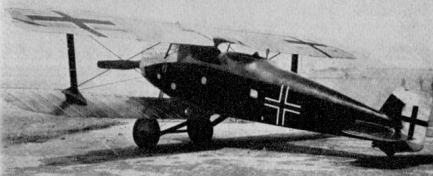
Hannover CL V (second version)
Brandenburg FD (BI)
A development of the type D, this aircraft featured the inward-sloping interplane struts to be seen for so long afterwards in the Austro-Hungarian Brandenburg two-seater C types. The tail surfaces were also considerably revised. Aircraft of this type were operated by the flying school of Hanseatische Flugzeug-Werke, Caspar Hamburg-Fuhlsbuttel, and three aircraft went to Austria. Engine, 110 h.p. Benz III. Span, 13.128 m. (43 ft. 0 7/8 in.). Length, 8.45 m. (27 ft. 8 7/8 in.). Height, 2.96 m. (9 ft. 8 1/2 in.). Area, 43.45 sq.m. (469 sq.ft.).
A development of the type D, this aircraft featured the inward-sloping interplane struts to be seen for so long afterwards in the Austro-Hungarian Brandenburg two-seater C types. The tail surfaces were also considerably revised. Aircraft of this type were operated by the flying school of Hanseatische Flugzeug-Werke, Caspar Hamburg-Fuhlsbuttel, and three aircraft went to Austria. Engine, 110 h.p. Benz III. Span, 13.128 m. (43 ft. 0 7/8 in.). Length, 8.45 m. (27 ft. 8 7/8 in.). Height, 2.96 m. (9 ft. 8 1/2 in.). Area, 43.45 sq.m. (469 sq.ft.).

Brandenburg FD (BI)
Brandenburg D
Some twelve machines of this type were built for the German Army in 1914. It was an orthodox two-seater with the pilot sitting aft. The fuselage structure was of steel tube with ply sheet covering, the remainder of the aircraft was of the usual wood and fabric medium. Engine, 110 h.p. Benz Bz II. Span, 13.128 m. (43 ft. 7/8 in.). Length, 8.455 m. (27 ft. 8 7/8 in.). Height, 2.96 m. (9 ft. 8 1/2 in.). Area, 43.46 sq.m. (469 sq.ft.).
Some twelve machines of this type were built for the German Army in 1914. It was an orthodox two-seater with the pilot sitting aft. The fuselage structure was of steel tube with ply sheet covering, the remainder of the aircraft was of the usual wood and fabric medium. Engine, 110 h.p. Benz Bz II. Span, 13.128 m. (43 ft. 7/8 in.). Length, 8.455 m. (27 ft. 8 7/8 in.). Height, 2.96 m. (9 ft. 8 1/2 in.). Area, 43.46 sq.m. (469 sq.ft.).

Brandenburg D
Brandenburg W
Although actually a pre-war design of 1914, twenty-seven aeroplanes of this type were supplied to the German Navy for reconnaissance and general duties. The crude, dinghy-like appearance of the floats may be noted. Engine, 150 h.p. Benz Bz III. Span, 16.5 m. (54 ft. 1 1/3 in.). Length 9.4 m (30 ft. 10 1/8 in.). Area, 57.85 sq.m. (625 sq.ft.). Weights: Empty, 1,200 kg (2,640 lb.). Loaded, 1,830 kg. (4,026 lb.). Speed, 90 km.hr. (56.25 m.p.h )
Although actually a pre-war design of 1914, twenty-seven aeroplanes of this type were supplied to the German Navy for reconnaissance and general duties. The crude, dinghy-like appearance of the floats may be noted. Engine, 150 h.p. Benz Bz III. Span, 16.5 m. (54 ft. 1 1/3 in.). Length 9.4 m (30 ft. 10 1/8 in.). Area, 57.85 sq.m. (625 sq.ft.). Weights: Empty, 1,200 kg (2,640 lb.). Loaded, 1,830 kg. (4,026 lb.). Speed, 90 km.hr. (56.25 m.p.h )
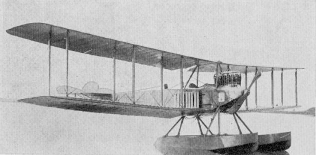
Brandenburg W
Brandenburg FB 1915
Only six examples of this, the first Brandenburg flying-boat, were supplied to the German Navy, which was not enthusiastic about flying-boats. The Austrian Navy, on the other hand, favoured this type and used it in the Adriatic with considerable success. Engine, 165 h.p. Austro-Daimler, Span, 16.0 m. (52 ft. 6 in.). Length, 10.105 m. (33 ft. 1 7/8 in.). Area, 46.0 sq.m. (497 sq.ft.). Weights: Empty, 1,140 kg. (2,508 lb.). Loaded, 1,620 kg. (3,564 lb.). Speed, 140 km.hr. (87.5 m.p.h.). Climb, 1,000 m. (3,280 ft.) in 8.5 min. Armament, one Parabellum machine-gun.
Only six examples of this, the first Brandenburg flying-boat, were supplied to the German Navy, which was not enthusiastic about flying-boats. The Austrian Navy, on the other hand, favoured this type and used it in the Adriatic with considerable success. Engine, 165 h.p. Austro-Daimler, Span, 16.0 m. (52 ft. 6 in.). Length, 10.105 m. (33 ft. 1 7/8 in.). Area, 46.0 sq.m. (497 sq.ft.). Weights: Empty, 1,140 kg. (2,508 lb.). Loaded, 1,620 kg. (3,564 lb.). Speed, 140 km.hr. (87.5 m.p.h.). Climb, 1,000 m. (3,280 ft.) in 8.5 min. Armament, one Parabellum machine-gun.
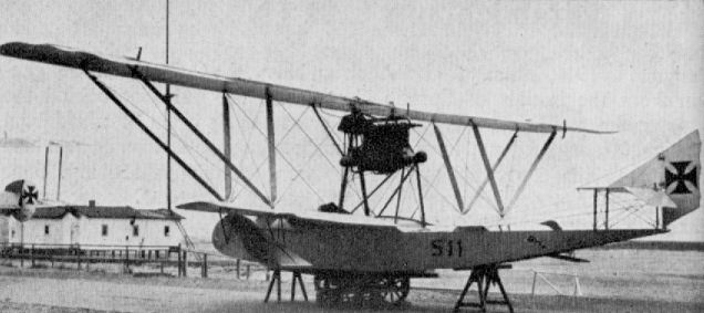
Brandenburg FB 1915
Brandenburg LW
Delivered in May 1916, the only LW built (No. 577) was claimed by Heinkel to be the first reconnaissance seaplane to be designed with a defensive gun, which statement is open to grave doubt. The redoubtable Heinkel claimed most of his designs as being the first, the best or the biggest! From the distinctive stagger and inward rake of the interplane struts, it is obvious the machine stemmed from the C I land machine built for Austro-Hungary. Engine, 160 h.p. Mercedes D III. Span, 12.4 m. (40 ft. 8 1/4 in.). Length, 9.5 m. (31 ft. 2 1/8 in.). Area, 42.6 sq.m. (460 sq.ft.). Weights: Empty, 994kg.(2.187lb.). Loaded, 1,555kg.(3,421 lb.). Speed, 130 km.hr. (81.25 m.p.h.). Climb, 1,000 m. (3,280 ft.) in 12 min. Armament, one Parabellum machine-gun.
Delivered in May 1916, the only LW built (No. 577) was claimed by Heinkel to be the first reconnaissance seaplane to be designed with a defensive gun, which statement is open to grave doubt. The redoubtable Heinkel claimed most of his designs as being the first, the best or the biggest! From the distinctive stagger and inward rake of the interplane struts, it is obvious the machine stemmed from the C I land machine built for Austro-Hungary. Engine, 160 h.p. Mercedes D III. Span, 12.4 m. (40 ft. 8 1/4 in.). Length, 9.5 m. (31 ft. 2 1/8 in.). Area, 42.6 sq.m. (460 sq.ft.). Weights: Empty, 994kg.(2.187lb.). Loaded, 1,555kg.(3,421 lb.). Speed, 130 km.hr. (81.25 m.p.h.). Climb, 1,000 m. (3,280 ft.) in 12 min. Armament, one Parabellum machine-gun.
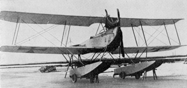
Brandenburg LW
Brandenburg NW
Thirty-two aircraft of this type were supplied to the German Navy during 1915. They were used on reconnaissance patrol duties, radio was carried and some machines were fitted with racks to carry ten 5-kg. bombs. The machine was an improvement of the pre-war W design and bore unmistakable resemblance to Heinkel's three-bay Albatros seaplanes. Engine, 160 h.p. Mercedes D III. Span, 16.5 m. (54 ft. 1 3/4 in.). Length, 9.4 m. (30 ft. 10 1/8 in.). Area, 57.85 sq.m. (625 sq.ft.). Weights: Empty, 1,020 kg. (2,244 lb.). Loaded, 1.650 kg. (3,630 lb.). Speed, 90 km.hr. (56.25 m.p.h.). Duration, 4 hr. Armament, none.
Brandenburg GNW
Further development of the NW saw the construction of sixteen GNWs during 1915 for use as unarmed two-seater patrol seaplanes. Speed was less than that of the NW, but the climb was considerably better. Engine, 160 h.p. Mercedes D III. Span, 16.2 m. (53 ft. 1 7/8 in.). Length. 9.88 m. (32 ft. 5 in.). Height, 2.553 m. (8 ft. 4 1/2 in.). Area, 55.15 sq.m. (596 sq.ft.). Weights: Empty, 1,100 kg. (2,420 lb.). Loaded, 1,743 kg. (3,835 lb.). Speed, 115 km.hr. (71.825 m.p.h.). Climb. 1,000 m. (3,280 ft.) in 9.5 min.
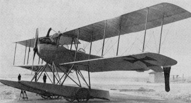
Brandenburg NW
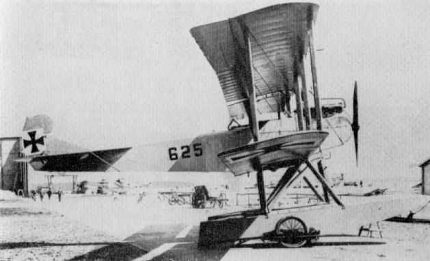
Brandenburg GNW
Brandenburg C.C.
Designed in 1916, initially for the Austrian Navy, the C.C. took its designation from the initials of Camilo Castiglioni, the financier behind the Brandenburg works. It was flown with great success by Lt. Banfield from the Austrian seaplane station at Pola. Some twenty-six machines were also supplied to the German Navy. These were fitted with 150 h.p. Benz engines, the Austrian machines having Hiero or Austro-Daimler power plants. The first machines were fitted with a single machine-gun; later twin guns were installed. Engine, 150 h.p. Benz Bz III. Span, 9.3 m. (30 ft. 6 1/8 in.). Length, 7.69 m. (25 ft. 2 3/4 in.). Height, 3.575 m. Area, 26.52 sq.m. (286 sq.ft.). Weights: Empty, 716 kg. (1,575 lb.). Loaded, 1,031 kg. (2,268 lb.). Speed, 175 km.hr. (109.375 m.p.h.). Climb, 1,000 m. (3,280 ft.) in 5 min. Armament, one or two Spandau machine-guns.
N.B. Data applies to batch "1137/1146".
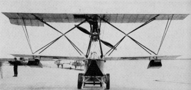
Brandenburg C.C. (No. 1348) Modified version with additional struts to brace wingtips. Note twin Spandau machine-gun installation.
Brandenburg GW
Developed as a torpedo strike aircraft during 1916, a total of twenty-six aircraft were supplied to the German Navy. The prototype had triple vertical tail surfaces, but the production machines had a simplified empennage. In production aircraft the frontal radiators of the prototype were re-located in the wings, and flush. The GW was capable of carrying a torpedo weighing 725 kg. (1,595 lb.), and chiefly operated from the seaplane station at Angernsee in Courland. Engines, two 160 h.p. Mercedes D III. Span, 21.56 m. (70ft.8 7/8in.). Length, 12.57m.(41 ft. 3in.). Height, 4.145 m. (13 ft. 7 1/8 in.). Area, 102.14 sq.m. (1,103 sq.ft.). Weights: Empty, 2,334 kg. (5,135 lb.). Loaded, 3,928 kg. (9,506 lb.). Speed, 102.14 km.hr. (64 m.p.h.). Climb, 1,000 m. (3,280 ft.) in 22 min. Armament, one torpedo, one defensive Parabellum machine-gun.
Brandenburg GDW
With enlarged proportions, this 1916 machine was a development of the GW and was designed to carry a heavier torpedo weighing 1,825 kg. (4,015 lb.). Only a single aircraft was built (No. 746), and it was probably seconded to training duties. Engines, two 200 h.p. Benz Bz IV. Span, 24.5 m. (80 ft. 4 5/8 in.). Length, 15.8 m. (51 ft. 10 1/8 in.). Height, 5.0 m. (16 ft. 4 in.). Area, 134 sq.m. (1,447 sq.ft.). Weights: Empty, 2,936 kg. (6,459 lb.). Loaded, 4,851 kg. (10,672 lb.). Speed, 130 km.hr. (81.25 m.p.h.). Climb, 1,000 m. (3,280 ft.) in 19.5 min.
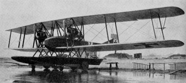
Brandenburg GDW
Brandenburg K.D.W.
During 1916 Ernst Heinkel prepared a design for a single-seat scout for the Austrian Army. Although conventional in most respects, the aircraft featured a novel system of wing bracing in the form of four vee struts joined in the centre of the wing bay by their apices. This arrangement gave a star configuration, and the aircraft was, in fact, dubbed "star strutter". The Brandenburg K.D. (Kampf Doppeldecker), as the type was designated, was license-built by the Austrian factories of Phonix and Ufag as the D I (Hansa Brandenburg D I (Ph) Series 28 and Hansa Brandenburg D I (Ufag) Series 65). Phonix subsequently developed the design on more conventional lines and introduced a more orthodox strut arrangement and empennage. This variant went into further production as their own D II and D III series.
In view of the demand for seaplane-station fighter defence aircraft and his considerable seaplane design experience, Heinkel decided to convert the K.D. to a seaplane fighter type as a stop gap, to reinforce the supply of Albatros W 4 and Rumpler 6BI seaplanes. In actual fact, the prototype adaptation amounted to little more than a slight increase in wingspan and mounting the K.D. airframe on a twin-float chassis. Later, the inclusion of a certain amount of fin area below the rear fuselage was found necessary to compensate the additional keel surface presented by the floats, and ultimately an upper fin was also added. Despite these modifications the K.D.W., like the landplane version, proved very difficult to fly. Due to the blanketing of the small rudder by the deep fuselage, directional stability was extremely poor, and recovery from a spin was more by luck than by any degree of skill.
The prototype (Marine No. 748) and early production models were fitted with the 150 h.p. Benz engine and a car-type radiator; likewise an interim production batch (Nos. 1067-1076), which also had additional outsplayed vee struts to brace the wingtips. All remaining aircraft were fitted with the 160 h.p. Maybach engine and flush-type radiator mounted in the centresection of the top wing to starboard of the centre. Exhaust manifolds were of the chimney type in the Benz-powered aircraft, except on the prototype, which had stub pipes. The Maybach K.D.W.s had a collector manifold with only a single ejector pipe showing on the starboard side.
Engines were neatly faired with hooded metal panels, which curved in from the upper longerons, giving a "head and shoulders" cross-section which afforded the pilot quite good forward vision. The fuselage itself was based on four spruce longerons, with ply formers forward and spruce spacers and transverse diagonal bracing members aft of the cockpit section. There was very little taper in fuselage depth. The curved decking maintained almost the same height as the depth between the longerons and extended right aft to the sternpost. The whole of the fuselage was plywood covered, as were also the vertical fins.
Tail surfaces were framed from steel tube and fabric covered. The rectangular rudder had a small balance portion atop the fuselage, but when the upper fin was introduced on the later models this was deleted. The large triangular tailplane, to which the unbalanced parallel chord elevators were hinged, was mounted directly on the upper longerons and braced to the underside of the fuselage with two streamlined steel struts.
The wings were of straightforward rectangular profile, of equal span and fabric covered. Their conventional wooden construction was based on two main spars, with a further auxiliary spar at approximately two-thirds chord, to which were hinged the unbalanced parallel-chord ailerons. The attachment point for the upper outboard vee of the "star-strut" interplane bracing was located almost at the extreme end of the aileron, and it was found in practice that the considerable overhang portion of the upper wing tended to flex as the ailerons were actuated, reducing the sensitivity of these controls. In consequence, a light steel-tube vee was fitted, splaying outward from the lower strut anchorage, to brace the upper wing more rigidly and make the aileron control more positive. The "star-struts" themselves were basically light-gauge circular steel tubes faired with plywood. Centre-section struts were of plain circular steel tube, like the auxiliary tip struts, and of inverted vee form.
The undercarriage chassis comprised a neat pair of N struts of steel tube faired with ply. The floats themselves, of single-step design, wedge-shaped forward and tapering to a vertical knife-edge at the stern, were wooden and built up on a framework of ply formers and spruce stringers and covered with mahogany ply. They were connected at the strut stations with rigid steel-tube spreaders and the complete chassis braced fore and aft with stranded cables.
An interesting point about the Heinkel K.D. and K.D.W. fighter prototypes is that they were developed structurally and aerodynamically before any thought seems to have been given to the armament. This was especially noticeable on the land aircraft, with guns mounted on the top wing. On the K.D.W.s a single synchronised Spandau machine-gun was mounted on the starboard side of the extreme nose, far beyond the reach of the pilot to correct any stoppage. Only on the final batch of twenty aircraft, delivered between October 1917 and February 1918, were twin Spandau guns fitted, clamped either side of the cockpit. By then the type was obsolescent and was being replaced by the far more efficient and flexible Brandenburg W 12. Altogether a total of 58 K.D.W.s were supplied.
Although these production batches of seaplanes may seem small, they must be viewed in comparison with total aircraft supplies, when by the end of the war a total of some 2,500 seaplanes had been produced, as compared with 44,000 aircraft for land warfare.
TECHNICAL DATA
Description: Single-seat seaplane fighting scout.
Manufacturer: Hansa und Brandenburgische Flugzeug-Werke G.m.b.H.
Power Plant:
One 150 h.p. Benz Bz III 6 cylinder in-line water-cooled engine.
One 160 h.p. Maybach Mb III 6 cylinder in-line water-cooled engine.
Dimensions: Span, 9.25 m. (30 ft. 4 1/4 in.). Length, 8 0 m. (26 ft. 3 in.). Height, 3.35 m. (10 ft. 11 7/8 in.). Area, 20 sq.m. (216 sq.ft.).
Weights: Empty, 940 kg. (2,068 lb.). Loaded, 1,210 kg (2,662 lb.).
Performance: Maximum speed, 170 km.hr. (106.25 m.p.h.). Climb, 1,000 m (3,280 ft.) in 5.9 min. 2,000 m. (6,560 ft.) in 14 min.; 3,000 m. (9,840 ft) in 21 mm. Duration 2 1/2 hr. with 160 litres fuel.
Armament: One fixed Spandau machine-gun forward mounted on starboard of nose. Last twenty aircraft were fitted with twin machine-guns.
Serial Numbers: Fifty-eight aircraft delivered. Marine Numbers: 748, 783, 784, 912-921, 1067-1076, 1380-1394, 1554-1573.
Brandenburg W 11
Built during late 1916, the W 11 was a slightly larger and more powerful version of the series-built K.D.W. single-seat fighter seaplane. Only two machines were built - Nos. 988-989. Engine, 200 h.p. Benz Bz IV. Span, 100 m. (32 ft. 9 3/4 in.). Length, 8.2 m. (26 ft. 10 7/8 in.). Height, 3.32 m. (10 ft. 10 5/8 in.). Area, 31.4 sq.m. (339 sq.ft.). Weights: Empty, 935 kg. (2,057 lb.). Loaded, 1,215 kg. (2,673 lb.). Speed, 176 km.hr. (110 m.p.h.). Armament, two Spandau machine-guns.
Brandenburg KW
Three of these two-seat armed reconnaissance seaplanes were supplied during 1916. Although designed for the 260 h.p. Mercedes D IVa engine, they were fitted with the 200 h.p. Benz Bz IV, in which form they were underpowered and suitable only for training duties. Engine, 200 h.p. Benz Bz IV. Span, 16.4 m. (53 ft. 9 3/4 in.). Length, 11.16 m. (36 ft. 7 3/8 in.). Height, 4.06 m. (13 ft. 3 7/8 in.). Area, 60.4 sq.m. (652 sq.ft.). Weights: Empty, 1,447 kg. (3,183 lb.). Loaded, 2,106 kg. (4,633 lb.). Speed, 134 km.hr. (83.725 m.p.h.). Climb, 1,000 m. (3,280 ft.) in 14.5 min. Duration, 6 hr. Armament, one Parabellum machine-gun.
Three of these two-seat armed reconnaissance seaplanes were supplied during 1916. Although designed for the 260 h.p. Mercedes D IVa engine, they were fitted with the 200 h.p. Benz Bz IV, in which form they were underpowered and suitable only for training duties. Engine, 200 h.p. Benz Bz IV. Span, 16.4 m. (53 ft. 9 3/4 in.). Length, 11.16 m. (36 ft. 7 3/8 in.). Height, 4.06 m. (13 ft. 3 7/8 in.). Area, 60.4 sq.m. (652 sq.ft.). Weights: Empty, 1,447 kg. (3,183 lb.). Loaded, 2,106 kg. (4,633 lb.). Speed, 134 km.hr. (83.725 m.p.h.). Climb, 1,000 m. (3,280 ft.) in 14.5 min. Duration, 6 hr. Armament, one Parabellum machine-gun.

Brandenburg KW
Brandenburg W 11
Built during late 1916, the W 11 was a slightly larger and more powerful version of the series-built K.D.W. single-seat fighter seaplane. Only two machines were built - Nos. 988-989. Engine, 200 h.p. Benz Bz IV. Span, 100 m. (32 ft. 9 3/4 in.). Length, 8.2 m. (26 ft. 10 7/8 in.). Height, 3.32 m. (10 ft. 10 5/8 in.). Area, 31.4 sq.m. (339 sq.ft.). Weights: Empty, 935 kg. (2,057 lb.). Loaded, 1,215 kg. (2,673 lb.). Speed, 176 km.hr. (110 m.p.h.). Armament, two Spandau machine-guns.
Built during late 1916, the W 11 was a slightly larger and more powerful version of the series-built K.D.W. single-seat fighter seaplane. Only two machines were built - Nos. 988-989. Engine, 200 h.p. Benz Bz IV. Span, 100 m. (32 ft. 9 3/4 in.). Length, 8.2 m. (26 ft. 10 7/8 in.). Height, 3.32 m. (10 ft. 10 5/8 in.). Area, 31.4 sq.m. (339 sq.ft.). Weights: Empty, 935 kg. (2,057 lb.). Loaded, 1,215 kg. (2,673 lb.). Speed, 176 km.hr. (110 m.p.h.). Armament, two Spandau machine-guns.
Brandenburg W 13
This comparatively large flying-boat was used only by the Austro-Hungarian Naval Air stations. Although the prototype was German designed (Ernst Heinkel) and built, production machines were built under licence by the Austrian Government factory Oeffag and Hungarian Government factory Ufag. A crew of two was carried. Engine, 350 h.p. Austro-Daimler. Span, 20.4 m. (66 ft. 9 1/4 in.). Length, 13.7 m. (44 ft. 11 3/8 in.). Height, 4.23 m. (13 ft. 10 1/2 in.). Area, 81.2 sq.m. (877 sq.ft.). Weights: Empty, 1,550 kg. (3,410 lb.). Loaded, 2,850 kg. (6,270 lb.). Armament, one Schwarzlose machine-gun. Small tactical bomb load.
This comparatively large flying-boat was used only by the Austro-Hungarian Naval Air stations. Although the prototype was German designed (Ernst Heinkel) and built, production machines were built under licence by the Austrian Government factory Oeffag and Hungarian Government factory Ufag. A crew of two was carried. Engine, 350 h.p. Austro-Daimler. Span, 20.4 m. (66 ft. 9 1/4 in.). Length, 13.7 m. (44 ft. 11 3/8 in.). Height, 4.23 m. (13 ft. 10 1/2 in.). Area, 81.2 sq.m. (877 sq.ft.). Weights: Empty, 1,550 kg. (3,410 lb.). Loaded, 2,850 kg. (6,270 lb.). Armament, one Schwarzlose machine-gun. Small tactical bomb load.
Brandenburg W 16
This single-seat seaplane fighter, designed for station defence, was built during 1916 and was of conventional wood and fabric construction with ply-skinned fuselage and floats. Only three aircraft were built, Nos. 1077-1079. Engine, 160 h.p. Oberursel U III. Span, 9.25 m. (30 ft. 4 1/8 in.). Length, 7.35 m. (24 ft. 13/8 in.). Height, 2.925 m. (9 ft. 7 1/8 in.). Area, 21.35 sq.m. (230.5 sq.ft.). Weights: Empty, 636 kg. (1,399 lb.). Loaded, 896 kg. (1,971 lb.). Speed, 170 km.hr. (106.25 m.p.h.). Climb, 1,000 m. (3,280 ft.) in 5 min., 3,000 m. (9,840 ft.) in 27 min. Duration, ca. 2 hr. Armament, two Spandau machine-guns.
This single-seat seaplane fighter, designed for station defence, was built during 1916 and was of conventional wood and fabric construction with ply-skinned fuselage and floats. Only three aircraft were built, Nos. 1077-1079. Engine, 160 h.p. Oberursel U III. Span, 9.25 m. (30 ft. 4 1/8 in.). Length, 7.35 m. (24 ft. 13/8 in.). Height, 2.925 m. (9 ft. 7 1/8 in.). Area, 21.35 sq.m. (230.5 sq.ft.). Weights: Empty, 636 kg. (1,399 lb.). Loaded, 896 kg. (1,971 lb.). Speed, 170 km.hr. (106.25 m.p.h.). Climb, 1,000 m. (3,280 ft.) in 5 min., 3,000 m. (9,840 ft.) in 27 min. Duration, ca. 2 hr. Armament, two Spandau machine-guns.
Brandenburg L 14
Built in 1917 for assessment by the German Air Force, this single-seater was obviously a development of the Austrian Brandenburg D I. Only a single prototype was produced. Engine, 200 h.p. Hiero. Span, 10.2 m. (33 ft. 5 5/8 in.). Length, 7.05 m. (23 ft. 1 3/4 in.). Area, 25.58 sq.m. (276 sq.ft.). Weights: Empty, 740 kg. (1,628 lb.). Loaded, 940 kg. (2,068 lb.).
Built in 1917 for assessment by the German Air Force, this single-seater was obviously a development of the Austrian Brandenburg D I. Only a single prototype was produced. Engine, 200 h.p. Hiero. Span, 10.2 m. (33 ft. 5 5/8 in.). Length, 7.05 m. (23 ft. 1 3/4 in.). Area, 25.58 sq.m. (276 sq.ft.). Weights: Empty, 740 kg. (1,628 lb.). Loaded, 940 kg. (2,068 lb.).
Brandenburg L 16
This experimental triplane was built during 1917 with differing radiator installations, but remained no more than a prototype. Engine, 185 h.p. Austro-Daimler. Span, 9.0 m. (29 ft. 6 3/8 in.). Length, 7.215 m. (23 ft. 8 in.). Height, 3.7 m. (12 ft. 1 3/4 in.). Area, 33.5 sq.m. (362 sq.ft.). Weights: Empty, 740 kg. (1,628 lb.). Loaded, 935 kg. (2,057 lb.). Speed, 190 km.hr. (118.75 m.p.h.). Armament, two fixed Spandau machine-guns.
This experimental triplane was built during 1917 with differing radiator installations, but remained no more than a prototype. Engine, 185 h.p. Austro-Daimler. Span, 9.0 m. (29 ft. 6 3/8 in.). Length, 7.215 m. (23 ft. 8 in.). Height, 3.7 m. (12 ft. 1 3/4 in.). Area, 33.5 sq.m. (362 sq.ft.). Weights: Empty, 740 kg. (1,628 lb.). Loaded, 935 kg. (2,057 lb.). Speed, 190 km.hr. (118.75 m.p.h.). Armament, two fixed Spandau machine-guns.
Brandenburg W 12
Work was begun on the Brandenburg W 12 in the autumn of 1916, in response to a request from the seaplane stations for a defence fighter equipped with a machine-gun to fire rearwards. Although the single-seat defence fighters (Albatros W 4, Brandenburg K.D.W., etc.) had proved a useful weapon to the naval service, they were completely defenceless against attack from the rear, and a solution to this vulnerability was sought in the design of the W 12. The elevated siting of the rear gun mounting gave an excellent all-round field of fire, including forward over the top wing. In addition, the aircraft itself was technically first class, for in spite of its weight and size, it was in no way inferior to the single-seaters in speed and manoeuvrability. The single-bay wings and absence of interplane bracing cables were a unique feature on a two-seater seaplane, and undoubtedly contributed to the excellent performance.
In January 1917 the prototype was completed at Briest works, but due to the water on the Havel River being frozen, it was shipped to the seaplane test establishment at Warnemunde. The initial test flight was a somewhat hectic affair in which the aircraft proved excessively tail heavy; however, a safe landing was contrived, and overnight modification of the wing structure corrected the centre of gravity and rectified this disconcerting trait. Although this prototype was later written off in an unlucky landing in breakers, the results thus far achieved, both in performance and general flying qualities, inspired sufficient confidence for a first series order to be placed.
The designer of the W 12 was Ernst Heinkel, who had fathered earlier successful designs from the Hansa Brandenburg works and who, a couple of decades later, was to produce the famous bombers from his own factories. As subsequent batches of W 12s were produced, so they differed slightly in detail, as seems to be inevitably the case with the majority of German naval aircraft types. However, the basic airframe remained substantially the same.
The fuselage was based on four main spruce longerons and spacers, with robust multi-ply formers forward of the cockpit supporting the engine bearers. The power-plant was either a 160 h.p. Mercedes D III or a 150 h.p. Benz Bz III according to series batch. Those with Mercedes motors were fitted with leading-edge-mounted radiators while W 12s with the Benz installation had a car-type radiator at the extreme nose. Immediately of the engine bearers, the longerons raked upwards towards the tail to give the elevated position for the gun mounting, which bestowed the improved field of fire. The slab sides tapered to a vertical knife-edge aft, with little or no taper in elevation, resulting in an extremely deep section at the tail end. This additional side area compensated for the float area and lack of vertical fin. The fuselage was plywood covered, and windows were provided in the floors of the cockpits to give improved downward visibility. The wooden cantilever tailplane was much thicker in section at the centre, and because of the resultant increase in airflow disturbance, the steel-tube-framed elevators had to be re-designed with a considerable degree of inverse taper to improve effectiveness. Mounted on top of the fuselage, the tailplane was well clear of the spray when taxi-ing, and the absence of bracing struts enabled the gunner to fire under the tail quite close in to the fuselage. The fabric-covered steel-tube rudder was attached to the fuselage sternpost, the balance portion extending below the fuselage to leave the area above the tailplane unrestricted for firing.
The wing structure was made compact and additionally strong in order to dispense with interplane bracing cables, enabling the gunner to fire through the wings. Construction was orthodox, although a deep aerofoil section was employed to provide the required strength factor. Plywood ribs, flanged with soft timber, were closely spaced on the two spruce main pars; both wings were of constant chord and, after the first batch of six aircraft, had rounded tips. The upper wing was a one-piece structure scured to the centre-section struts; the cut-out was shallow in the first batch, but the reduction of stagger in later series necessitated a much deeper cut-out. Ailerons of welded steel-tube framing were fitted, and control cables were designed to provide independent operation should any combat damage occur. Later batches of aircraft were fitted with four ailerons, connected with a link strut, and the ample aileron area contributed to the W 12's outstanding manoeuvrability.
The floats were supported on a chassis of steel-tube struts, faired with plywood and attached with ball joints. Additional "N" struts braced the floats to the wings at the junction of the interplane struts, lending additional rigidity to the wing cellule. The floats themselves were of wood; a basic framework of formers and stringers being covered with high-grade maritime three-ply.
On entering service with the seaplane stations, the Brandenburg W 12 soon proved itself an excellent weapon against the Allied seaplanes. Particularly pleased to receive the W 12 were the pilots at Zeebrugge, who had suffered at the hands of the large, well-armed, British flying-boats in the North Sea. Oberleutnant Christiansen soon distinguished himself as a capable exponent of the W 12, and probably his most spectacular victory was the shooting down in flames of the British non-rigid airship C 27 on 17th December 1917. A colleague of Christiansen's at this time was a midshipman, von Wyk, who between the wars became famous as the pilot of the giant twelve-engined Dornier Do X.
W 12s were also operated on reconnaissance, often venturing to British coastal waters. When used on such duties one of the forward-firing guns was dispensed with and radio apparatus carried in its stead.
TECHNICAL DATA
Description: Two-seat fighter seaplane.
Manufacturer: Hansa und Brandenburgische Flugzeug-Werke G.m.b.H.
Power Plant:
One 160 h.p. Mercedes D III 6 cylinder in-line water-cooled engine.
One 150 h.p. Benz Bz III 6 cylinder in-line water-cooled engine.
Dimensions: Span, 112m. (36 ft. 9 in.). Length, 9 6 m. (31 ft. 6 in.). Height, 3.3 m. (10 ft. 10 in.). Area, 35.3 sq.m. (381.25 sq.ft.).
Weights: Empty, 997 kg. (2,193.4 lb.). Loaded, 1,454 kg. (3,198.8 lb.).
Performance: Maximum speed, 159.5 km.hr. (100 m.p.h.). Climb, 1,000 m. (3,280 ft.) in 7 min.; 2,000 m. (6,560 ft.) in 18-9 min. Ceiling, 16,400 ft. Endurance, 3 1/2 hrs.
Armament: One or two fixed Spandau machine-guns and one manually operated Parabellum in rear cockpit.
Serial Numbers: One aircraft, Marine No. 2016, was experimentally fitted with vee-eight-type motor, probably 195 h.p. Benz Bz IIIb. 146 aircraft supplied,
Marine numbers:
1011-1016, 160 h.p. Mercedes, two machine-guns.
1178 1187, 150 h.p. Benz, two machine-guns.
1395-1414, 150 h.p. Benz, two machine-guns.
2000-2019, 150 h.p. Benz, two machine-guns (except 2016 above).
2023-2052, 150 h.p. Benz, three machine-guns.
2093-2132, 160 h.p. Mercedes, two machine-guns.
2217-2236, 160 h.p. Mercedes, two machine-guns, also radio fitted.
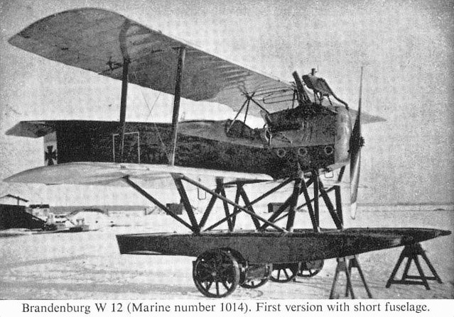
Brandenburg W 12 (Marine number 1014). First version with short fuselage
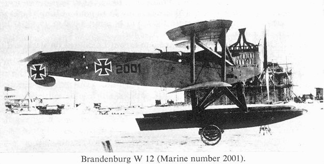
Brandenburg W 12 (Marine number 2001).
Brandenburg W 17
First of the diminutive single-seat flying-boats. No details available, but doubtless data was not greatly dissimilar to that of W 18 which followed. Provision for two Spandau machine-guns.
First of the diminutive single-seat flying-boats. No details available, but doubtless data was not greatly dissimilar to that of W 18 which followed. Provision for two Spandau machine-guns.
Brandenburg W 18
Although only one machine (No. 2138) was supplied to the German Navy in 1917, a slightly modified version powered with 200 h.p. Hiero engine was supplied to the Austro-Hungarian Navy. This single-seat flying-boat fighter was an improvement on the similar C.C. type developed for the Austrians. Engine, 150 h.p. Benz Bz III. Span, 10.7 m. (35 ft. 1 1/4 in.). Length, 8.15 m. (26 ft. 8 7/8 in.). Height, 3.45 m. (11 ft. 3 7/8 in.). Area, 34.38 sq.m. (271 sq.ft.). Weights: Empty, 875 kg. (1,925 lb.). Loaded, 1,145 kg. (2,519 lb.). Speed, 160 km.hr. (100 m.p.h.). Climb, 1,000 m. (3,280 ft.) in 5 min., 3,000 m. (9,840 ft.) in 23 min. Armament, two Spandau machine-guns. (Above aircraft had only one fitted when photographed.)
Although only one machine (No. 2138) was supplied to the German Navy in 1917, a slightly modified version powered with 200 h.p. Hiero engine was supplied to the Austro-Hungarian Navy. This single-seat flying-boat fighter was an improvement on the similar C.C. type developed for the Austrians. Engine, 150 h.p. Benz Bz III. Span, 10.7 m. (35 ft. 1 1/4 in.). Length, 8.15 m. (26 ft. 8 7/8 in.). Height, 3.45 m. (11 ft. 3 7/8 in.). Area, 34.38 sq.m. (271 sq.ft.). Weights: Empty, 875 kg. (1,925 lb.). Loaded, 1,145 kg. (2,519 lb.). Speed, 160 km.hr. (100 m.p.h.). Climb, 1,000 m. (3,280 ft.) in 5 min., 3,000 m. (9,840 ft.) in 23 min. Armament, two Spandau machine-guns. (Above aircraft had only one fitted when photographed.)
Brandenburg W 25
Further development of K.D.W. single-seat seaplane with normal interplane bracing. Only one example was constructed, No. 2258, first with ailerons on top wing only, later (as illustrated) with ailerons at all wingtips connected by a link strut. Engine, 150 h.p. Benz Bz III. Span, 10.4 m. (34 ft. 1 1/2 in.). Length, 8.8 m. (28 ft. 10 1/2 in.). Height, 3.45 m. (11 ft. 3 7/8 in.). Area, 36.53 sq.m. (395 sq.ft.). Weights: Empty, 918 kg. (2,221 lb.). Loaded, 1,182 kg. (2,600 lb.). Speed, 160 km.hr (100 m.p.h.). Climb, 1,000 m. (3,280 ft.) in 6 1/2 min. Duration, 2 1/2 hr. Armament, two Spandau machine-guns.
Further development of K.D.W. single-seat seaplane with normal interplane bracing. Only one example was constructed, No. 2258, first with ailerons on top wing only, later (as illustrated) with ailerons at all wingtips connected by a link strut. Engine, 150 h.p. Benz Bz III. Span, 10.4 m. (34 ft. 1 1/2 in.). Length, 8.8 m. (28 ft. 10 1/2 in.). Height, 3.45 m. (11 ft. 3 7/8 in.). Area, 36.53 sq.m. (395 sq.ft.). Weights: Empty, 918 kg. (2,221 lb.). Loaded, 1,182 kg. (2,600 lb.). Speed, 160 km.hr (100 m.p.h.). Climb, 1,000 m. (3,280 ft.) in 6 1/2 min. Duration, 2 1/2 hr. Armament, two Spandau machine-guns.
Brandenburg W 19
With the expansion and reorganisation of the German Naval flying services in 1917 it was decided to concentrate the fighter establishments mainly at Borkum and Zeebrugge and to use Norderney chiefly as a reconnaissance station. By the end of that year, after the Brandenburg W 12 had been in use some six months, the need was found for a two-seat fighter machine of greater duration, and to serve this requirement the Brandenburg W 19 began operations in January 1918.
Basically similar to the W 12, the W 19 was a considerably larger aircraft, spanning almost 10 ft. more and being about 3 ft. 6 in. greater in length. Increased fuel capacity gave it a greater radius of action. Although so much larger than the W 12, performance was not materially affected due to the installation of the more powerful 260 h.p. Maybach engine, which represented an increase of some 110 h.p. over the W 12. A neat spinner improved the nose-entry lines, and a frontal radiator was fitted adjacent to the centre-section leading edge. The remainder of the fuselage was like that of the W 12, maintaining the same proportions with the characteristic upward rake and plywood covering. The tail assembly differed little, apart from the profile of the tailplane, which was changed to a large semi-circular shape. The parallel-chord wings had their tips modified to a more bluntly rounded shape: the near semicircular centre-section cut-out was maintained. Due to the considerable increase in span, the wings were rigged with two sets of interplane struts and braced in all bays with stranded cables, although on certain aircraft bracing was omitted from the inboard bay to enable the gunner to shoot through the wings. Plain unbalanced ailerons were fitted at all four wingtips and connected with a link strut. The typical Brandenburg float chassis was retained, likewise the wooden floats with wedge bows and knife-edge stern.
In patrol work Brandenburg W 19s would often reconnoitre ahead while their W 12 colleagues waited upon the surface - when conditions were suitable - and would return to collect them should surface or airborne targets be sighted. Frequently one of the large twin-engined F 2a flying-boats patrolling from Felixstowe or Yarmouth would be sighted on the water, having been forced to alight with engine trouble, and would be attacked. During 1918, combats between these big boats and the fighters from Borkum and Zeebrugge became fairly commonplace.
On 4th June 1918 a patrol of live flying-boats made up of aircraft from both Felixstowe and Yarmouth (under command of Capt. Leckie of the latter station) set course for Borkum, and about 10 miles from Terschelling one boat had to alight with engine trouble. The now four-strong flight was soon attacked by some fifteen variously assorted Brandenburg W 12s, W 19s and W 29 monoplanes, and an exceedingly hot combat ensued. The living-boats, maintaining formation to concentrate their fire, managed to cut off three of the Brandenburgs and concentrate their attack upon these seaplanes, one soon succumbing to their fire, side slipping and spinning into the sea. In turn, one of the F 2as was forced down and eventually interned by a Dutch trawler; another boat had to alight with a broken petrol pipe, but after making a temporary repair was able to take off again. After losing another seaplane the Germans retired, and during the flight back to Borkum shot up the first F 2a, which had alighted with engine trouble before the combat took place. The crew of the surfaced flying-boat vigorously returned the fire and managed to bring down a Brandenburg, whereupon another alighted near by to rescue the crew. Shortage of petrol forced the enemy to withdraw, and the F 2a was able to resume taxi-ing towards Terschelling Island. However, when within only a few hundred yards of beaching, it was again attacked by a Brandenburg W 19 - No. 2239 - which at last managed to set it on fire. The crew of three nevertheless managed to get safely ashore.
That chivalry existed between opponents over the North Sea is evidenced by an incident in June 1918 when a Felixstowe boat commanded by Lt.-Col. Robertson was shot down by live seaplanes from Zeebrugge. Crash landing, the boat tore off its wings and turned turtle: eventually Robertson was able to clamber upon the upturned hull. One of the German seaplanes alighted and taxied alongside to tell Robertson that he was near the Allied coast and ask him if he wished to be taken back to Zeebrugge or take a chance on being picked up by an Allied machine or vessel. The doughty colonel elected to remain with his wreck, whereupon his victor took a photograph of him, waved a friendly adieu and flew back to Zeebrugge. However, not a few Allied aircrews owed their lives, after being forced to alight, to being picked up by German seaplanes.
TECHNICAL DATA
Description: Two-seat fighting patrol seaplane (long range).
Manufacturer: Hansa und Brandenburgische Flugzeug-Werke G.m.b.H.
Power Plant: One 260 h.p. Maybach Mb IV 6 cylinder in-line water-cooled engine.
Dimensions: Span, 13.80 m. (45 ft. 3 3/8 in.) Length, 10.65 m. (34 ft. 11 3/8 in.). Height, 4.10 m. (13 ft. 5 1/2 in.). Area, 57.8 sq.m. (624.25 sq.ft.).
Weights: Empty, 1,435 kg. (3,157 lb.). Loaded, 2,005 kg. (4,411 lb.).
Performance: Maximum speed, 150.5 km.hr. (94 m.p.h.). Climb, 1,000 m. (3,280 ft.) in 6.4 min.; 2,000 m. (6,560 ft.) in 18 9 min.; 3,000 m. (9,840 ft.) in 230 min. Endurance, ca. 5 hr.
Armament: First three aircraft had one fixed Spandau machine-gun forward and one manually operated Parabellum machine-gun in rear cockpit. All remaining aircraft fitted twin Spandaus forward.
Serial Numbers: Fifty-five aircraft delivered. Marine numbers 1469-1471, 2207-2216, 2237 fitted experimentally with cannon armament, 2238-2257, 2259-2278, 2537.
Brandenburg W 20
This little single-seat flying-boat was designed during 1917 for carrying aboard U-boats. It could be dismantled in 1 3/4 min. and stowed into space measuring only 20 ft. X 6 ft.; re-assembly took 2 3/4 min. As the type of submarine for which it was intended never went into service, only three examples of the W 20 were built. The first, No. 1551, had no interplane struts; these members were, however, added to the structure of Nos. 1552 - 1553, which also had the lower wing increased in span. Engine, 80 h.p. Oberursel UO. Span, 5.8 m. (19 ft. 0 3/8 in.), "1551"; 6.8 m. (22 ft. 3 3/4 in.), "1552/3". Length, 5.91 m. (19 ft. 4 5/8 in.), "1551"; 5.925 m. (19 ft. 5 1/8 in.), "1552/3". Area, 14.95 sq.m. (161 sq.ft.), "1551"; 15.82 sq.m. (171 sq.ft.), "1552/3". Weights: Empty, 396 kg. (871 lb.). Loaded, 568 kg. (1,250 lb.). Climb, 1,000 m. (3,280 ft.) in 14.9 min. Duration, 1 1/4 hr. Armament, none.
This little single-seat flying-boat was designed during 1917 for carrying aboard U-boats. It could be dismantled in 1 3/4 min. and stowed into space measuring only 20 ft. X 6 ft.; re-assembly took 2 3/4 min. As the type of submarine for which it was intended never went into service, only three examples of the W 20 were built. The first, No. 1551, had no interplane struts; these members were, however, added to the structure of Nos. 1552 - 1553, which also had the lower wing increased in span. Engine, 80 h.p. Oberursel UO. Span, 5.8 m. (19 ft. 0 3/8 in.), "1551"; 6.8 m. (22 ft. 3 3/4 in.), "1552/3". Length, 5.91 m. (19 ft. 4 5/8 in.), "1551"; 5.925 m. (19 ft. 5 1/8 in.), "1552/3". Area, 14.95 sq.m. (161 sq.ft.), "1551"; 15.82 sq.m. (171 sq.ft.), "1552/3". Weights: Empty, 396 kg. (871 lb.). Loaded, 568 kg. (1,250 lb.). Climb, 1,000 m. (3,280 ft.) in 14.9 min. Duration, 1 1/4 hr. Armament, none.
Brandenburg W 26
Designed as a long-range two-seat, patrol seaplane with an endurance of up to eight hours, three W 26s were constructed, Nos. 1739-1741. It was a large machine and seems to have owed something to the Friedrichshafen seaplanes in appearance. Both transmitting and receiving radio apparatus was carried. Engine, 260 h.p. Mercedes, D IVa. Span, 18.8 in. (61 ft. 8 1/4 in.). Length, 13.015 m. (42 ft. 8 3/8 in.). Area, 86.3 sq.m. (932 sq.ft.). Weights: Empty, 1,675 kg. (3,685 lb.). Loaded, 2,490 kg. (5,478 lb.). Speed, 135 km.hr. (84.35 m.p.h.). Duration, 8 hr. Armament, one Parabellum and one or two Spandau machine-guns.
Designed as a long-range two-seat, patrol seaplane with an endurance of up to eight hours, three W 26s were constructed, Nos. 1739-1741. It was a large machine and seems to have owed something to the Friedrichshafen seaplanes in appearance. Both transmitting and receiving radio apparatus was carried. Engine, 260 h.p. Mercedes, D IVa. Span, 18.8 in. (61 ft. 8 1/4 in.). Length, 13.015 m. (42 ft. 8 3/8 in.). Area, 86.3 sq.m. (932 sq.ft.). Weights: Empty, 1,675 kg. (3,685 lb.). Loaded, 2,490 kg. (5,478 lb.). Speed, 135 km.hr. (84.35 m.p.h.). Duration, 8 hr. Armament, one Parabellum and one or two Spandau machine-guns.
Brandenburg W 27
A development of the W 12, the W 27 did not differ drastically from the earlier machine; most noticeable variation was the "I"-type interplane and centre-section struts. Only a single aircraft was built, No. 2202, and it was powered with the comparatively new 195 h.p. Benz Bz IIIb engine, an eight-cylinder vee type. The performance did not warrant a production order, and the W 27 finished its days on training duties. Engine, 195 h.p. Benz IIIb. Span, 11.2 m. (36 ft. 9 in.). Length, 9.23 m. (30 ft. 3 1/2 in.). Height, 3.057 m. (10 ft. 0 1/4 in.). Area, 36.06 sq.m. (389 sq.ft.). Weights: Empty, 1,109 kg. (2,440 lb.). Loaded, 1,619 kg. (3,562 lb.). Armament, one Parabellum and two Spandau machine-guns.
Brandenburg W 32
A still further development of the W 12 two-seat patrol fighter theme was the W 32, in effect a re-engined W 27. Five machines were originally scheduled: Nos. 2282-2286, but No. 2285 and No. 2286 were cancelled in April 1918. Engine, 160 h.p. Mercedes D III. Span, 11.2 m . (36 ft. 9 in.). Length, 9.23 m. (30 ft. 3 1/2 in.). Height, 3.25 m. (10 ft. 7 7/8 in.). Area, 36.06 sq.m. (389 sq.ft.). Weights: Empty, 1,063 kg. (2,339 lb.). Loaded, 1,544 kg. (3,397 lb.). Climb, 1,000 m. (3,280 ft.) in 11.6 min. Armament, one Parabellum and two Spandau machine-guns.
Brandenburg W 29
Without doubt the most notable of Heinkel's designs to come from the Brandenburg factory was the W 29 sea monoplane, which came into operation in April 1918.
In the early days of that year Christiansen had mentioned to Heinkel that a successor to the W 12 would soon be needed to maintain the edge in superiority over the Allied types then being encountered over the North Sea. Within the limits of the engines and material available # not to mention time # Heinkel concluded that only a monoplane, with its reduced drag and frontal area, could achieve the required results.
To conserve valuable time, the Brandenburg W 29 became what was virtually a monoplane version of the W 12. The fuselage, with the 150 h.p. Benz Bz III engine installation and car-type nose radiator, remained practically the same; the exhaust manifold was dispensed with and stub pipes fitted on the port side. As before, the whole of the fuselage raked upwards aft of the engine and remained a ply-covered wooden structure; the whole of the tail assembly, except for a slight alteration in tailplane shape, was the same as the W 12. The flotation gear and chassis arrangement also remained unchanged.
The monoplane wing was increased in span and chord until its area approximated that of the W 12. In plan form it was almost rectangular, there being only 1 1/2° of taper on both leading and trailing edges. The tips were blunt with rounded corners, and the horn-balanced ailerons were set within the contour; there were quadrant cut-outs at the roots of the trailing edges. The wings were rigged with 3° 20' dihedral in each panel and differed in depth and section throughout their length. At the root the section was thin and had some of incidence, the wing section then being gradually thickened until at the point where the float-chassis bracing struts were located it reached its maximum depth and was almost twice as thick as at the root, having been developed from a high-speed to a high-lift section. From then on towards the tip it again reduced in thickness, eventually becoming almost the same as the root section. Construction was conventional in being based on two wooden main spars with the ribs built up of ply and soft wood, the whole being fabric covered.
Armament of the Brandenburg W 29 varied. Of the seventy-eight machines supplied, forty were fitted with only one forward gun but carried radio equipment; the remaining aircraft were fitted with twin Spandaus and dispensed with the radio gear. Christiansen, on testing the prototype at Brandenburg, has been reported as being so pleased with the aircraft that he insisted on flying it back to Zeebrugge the next day for operational use!
Although not possessed of great range, it proved possible to evolve tactics to circumvent this shortcoming. When surface conditions were favourable the W 29 seaplanes would sit upon the waters of the North Sea while aircraft of greater range (W 19s, etc.) scouted ahead and then returned for # or called up # the W 29s as necessary.
A unique victory of the Brandenburg W 29s from Borkum seaplane station was the sinking of three British motor boats on 11th August 1918, the same day that Lt. Cully took off in his Sopwith Camel from a lighter in the North Sea to destroy the Zeppelin L. 53. A patrol of fourteen W 29s returning to Borkum encountered a flotilla of six C.M.B.s (Coastal Motor Boats: the equivalent of M.T.B.s in current nomenclature), which had earlier been lowered from larger surface craft to search for German mine sweepers. The W 29s immediately dived in to attack. The C.M.B.s, capable of some 40 knots, split up in twisting evasive action, but the seaplanes had every advantage, their machine-guns stabbing through the light ply superstructure of the boats with effortless ease. The boats crews returned the fire with their Lewis guns, but with little effect against such devastating odds, and one C.M.B. soon hove to with a silent engine-room. The Brandenburgs instantly concentrated upon this hapless target, literally ripping it apart with their machine-gun fire, so that it rapidly began to founder. Immediately a sister boat crashed alongside, taking off all the crew and wounded. Yet two more of the torpedo boats were destroyed by the seaplanes, the crews being taken off in turn by the surviving boats. A long rearguard action was fought by the three survivors, which, in parlous condition, eventually managed to reach the coast of Holland, where they were interned by the authorities.
Earlier in the year 1918, on the night of 22nd/23rd April, the famous raid on the Zeebrugge Mole by the Royal Navy had taken place. It is of interest to relate how little the seaplane operations from that location were affected. With typical German thoroughness the railway sheds on the Mole had a layer of reinforced concrete laid over them and had been converted into a seaplane station. When not in use the seaplanes were shackled to flat-top railway wagons under this cover, and when required for action the wagons were shunted on to the quay, where quayside cranes offloaded the aircraft directly into the water. A locomotive was constantly kept "in steam" ready to withdraw all aircraft-loaded wagons to the mainland should at any time a Naval assault take place. Consequently, when the Royal Navy raided the Mole and blocked the harbour the seaplanes were all withdrawn to the shore and were able to resume operations almost immediately.
At this time Oblt. R. Christiansen was commanding the Zeebrugge station with some fifty pilots under his control, and was not slow to exact revenge when, two days later, leading a flight of seven W 29s, he attacked two F 2a flying-boats from Felixstowe, shooting one down in flames.
TECHNICAL DATA
Description: Two-seat sea monoplane fighter.
Manufacturer: Hansa und Brandenburgische Flugzeug-Werke G.m.b.H.
Power Plant: One 150 h.p. Benz Bz III six cylinder in-line water-cooled engine.
N.B. Last four aircraft to be built were fitted with uprated Benz Bz IIIa of 185 h.p.
Dimensions: Span, 13.5 m. (44 ft. 3 1/2 in.). Length, 9.36 m. (30 ft. 8 1/2 in.). Height 30 m. (9 ft. 10 1/8 in.). Area, 32.2 sq.m. (347.75 sq.ft.).
Weights: Empty, 1,000 kg. (2,200 lb.). Loaded, 1,494 (3,286.8 lb.).
Performance: Maximum speed, 175 km.hr. (109.375 m.p.h.). Climb, 1,000 m. (3,280 ft.) in 6 min.; 2,000 m. (6,560 ft.) in 13 min.; 3,000 m. (9,840 ft.) in 23 min. Ceiling, 16,400 ft. Endurance, ca. 4 hr.
Armament: Forty aircraft with one fixed Spandau machine-gun forward (on starboard side) and one manually operated Parabellum machine-gun in rear cockpit. Thirty-eight aircraft fitted with additional Spandau forward.
Serials: Marine numbers of the seventy-eight aircraft delivered were: 2203-2206, 2287-2300 (1), 2501-2506(1), 2507-2536, 2564-2583(1), 2584-2587.
(1) One forward gun only.
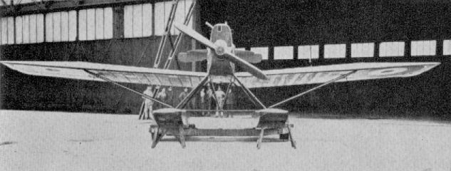
Brandenburg W 33 (W29 ???)
Brandenburg W 33
Twenty-six W 33s had been delivered by the end of the war and were mostly in use at the North Sea air stations, augmenting the W 29, of which the W 33 was a larger and more powerful variant. Although spanning over 50 ft., it was remarkably clean, as may be seen from the illustration. This depicts a machine brought over to the Isle of Grain for evaluation after the Armistice, and the R.A.F. roundels may just be discerned below the wings. Engine, 245 h.p. Maybach Mb IV. Span, 15.85 m. (52 ft. 0 in.). Length, 11.10 m. (36 ft. 5 1/8 in.). Height, 3.37 m. (11 ft. 0 5/8 in.). Area, 44 sq.m. (475 sq.ft.). Weights: Empty, 1,420 kg. (3,124 lb.). Loaded, 2,050 kg. (4,510 lb.). Speed, 173 km.hr. (108.125 m.p.h.). Climb, 1,000 m. (3,280 ft.) in 5.4 min. Armament, one Parabellum and two Spandau machine-guns. One aircraft, No. 2543, fitted with cannon. Naval Nos. 2538-2563.
Twenty-six W 33s had been delivered by the end of the war and were mostly in use at the North Sea air stations, augmenting the W 29, of which the W 33 was a larger and more powerful variant. Although spanning over 50 ft., it was remarkably clean, as may be seen from the illustration. This depicts a machine brought over to the Isle of Grain for evaluation after the Armistice, and the R.A.F. roundels may just be discerned below the wings. Engine, 245 h.p. Maybach Mb IV. Span, 15.85 m. (52 ft. 0 in.). Length, 11.10 m. (36 ft. 5 1/8 in.). Height, 3.37 m. (11 ft. 0 5/8 in.). Area, 44 sq.m. (475 sq.ft.). Weights: Empty, 1,420 kg. (3,124 lb.). Loaded, 2,050 kg. (4,510 lb.). Speed, 173 km.hr. (108.125 m.p.h.). Climb, 1,000 m. (3,280 ft.) in 5.4 min. Armament, one Parabellum and two Spandau machine-guns. One aircraft, No. 2543, fitted with cannon. Naval Nos. 2538-2563.
Hanuschke Monoplane
This 1915 monoplane has been reported as the type on which Fokker based his E I series. Undoubtedly both machines were influenced by the French Morane-Saulnier Type H of pre-war manufacture. Engine was probably 80 h.p. Oberursel rotary.
This 1915 monoplane has been reported as the type on which Fokker based his E I series. Undoubtedly both machines were influenced by the French Morane-Saulnier Type H of pre-war manufacture. Engine was probably 80 h.p. Oberursel rotary.
Hergt Monoplane
This diminutive monoplane was designed and built at F.E.A. 1 Altenburg as a private venture by F. D. Hergt during 1918 and flown by Mario Scherff. Of interest are the ply-skinned wings, which medium also covered the fuselage. The sturdy crash pylon is also noteworthy. Engine, 80 h.p. Gnome. Span, 6.0 m. (19 ft. 8 1/4 in.). Length, 5.2 m. (17 ft. 0 3/4 in.). Speed, 125 km.hr. (78.125 m.p.h.). Armament, none.
This diminutive monoplane was designed and built at F.E.A. 1 Altenburg as a private venture by F. D. Hergt during 1918 and flown by Mario Scherff. Of interest are the ply-skinned wings, which medium also covered the fuselage. The sturdy crash pylon is also noteworthy. Engine, 80 h.p. Gnome. Span, 6.0 m. (19 ft. 8 1/4 in.). Length, 5.2 m. (17 ft. 0 3/4 in.). Speed, 125 km.hr. (78.125 m.p.h.). Armament, none.
Jeannin Taube
Developed by pioneer airman Emil Jeannin, this machine was one of the most elegant of the 1914 Taube types. Fuselage was of steel tube and the flexible, warp-control wings of spruce and ash. Engine, 120 h.p. Argus As II. Span, 13.87 m. (45 ft. 6 1/8 in.). Length, 9.69 m. (31 ft. 9 7/8 in.). Height, 2.97 m. (9 ft. 9 in.). Area, 2.97 sq.m. (233 sq.ft.). Weights: Empty, 705 kg. (1,551 lb.). Loaded. 1,035 kg. (2,277 lb.). Duration, 4 hr. Speed, ca. 100 km.hr. (62.5 m.p.h.).
Developed by pioneer airman Emil Jeannin, this machine was one of the most elegant of the 1914 Taube types. Fuselage was of steel tube and the flexible, warp-control wings of spruce and ash. Engine, 120 h.p. Argus As II. Span, 13.87 m. (45 ft. 6 1/8 in.). Length, 9.69 m. (31 ft. 9 7/8 in.). Height, 2.97 m. (9 ft. 9 in.). Area, 2.97 sq.m. (233 sq.ft.). Weights: Empty, 705 kg. (1,551 lb.). Loaded. 1,035 kg. (2,277 lb.). Duration, 4 hr. Speed, ca. 100 km.hr. (62.5 m.p.h.).
Junkers J 1
First product of the Junkers factory was the J 1, also designated E I. It was an angular, all-metal monoplane of astoundingly advanced appearance. Its first test flight was made by Lt. v. Mallinckrodt at Doberitz on 12th December 1915. The thin sheet iron with which the aircraft was covered gave rise to the "Tin Donkey'" appellation which was applied to this an subsequent Junkers types, although later machines were covered with dural sheet. Only the single J 1 was built. Engine, 120 h.p. Mercedes D II. Span, 12.95 m. (42 ft. 5 5/8 in.). Length, 7.43 m. (24 ft. 4 5/8 in.). Height, 3.13 m. (10 ft. 3 1/4 in.). Area, 24.64 sq.m. (266 sq.ft.). Weights: Empty, 900 kg. (1,980 lb.). Loaded, 1,010 kg. (2,222 lb.). Speed, 160 km.hr. (100 m.p.h.).
First product of the Junkers factory was the J 1, also designated E I. It was an angular, all-metal monoplane of astoundingly advanced appearance. Its first test flight was made by Lt. v. Mallinckrodt at Doberitz on 12th December 1915. The thin sheet iron with which the aircraft was covered gave rise to the "Tin Donkey'" appellation which was applied to this an subsequent Junkers types, although later machines were covered with dural sheet. Only the single J 1 was built. Engine, 120 h.p. Mercedes D II. Span, 12.95 m. (42 ft. 5 5/8 in.). Length, 7.43 m. (24 ft. 4 5/8 in.). Height, 3.13 m. (10 ft. 3 1/4 in.). Area, 24.64 sq.m. (266 sq.ft.). Weights: Empty, 900 kg. (1,980 lb.). Loaded, 1,010 kg. (2,222 lb.). Speed, 160 km.hr. (100 m.p.h.).
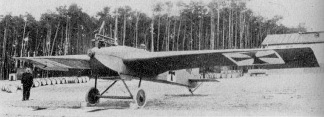
The monoplane was far from being a novelty, when the Junkers J.I was rolled out in early December 1915 and prepared for its inital test hop on the 12th. What was different about this one, however, went beyond the smooth, fully cantilevered exterior and into the all-metal structure and use of the Junkers-devised, thick sectioned, high lift wing. Built purely as a research machine, the two seat 120hp Mercedes D III powered Junkers J.I could accommodate a flight test observer. Military interest in the J.I was quickened by its warlike potential and it was trialled against a Rumpler C I, a machine that was considered the best in its class. Compared with the C I, the Junkers machine was 7mph faster on the level, at 106mph and even faster in a shallow dive. However, being built of steel, the J.I was heavy and, hence, markedly inferior to the Rumpler biplane in terms of climbing performance, earning the nicknames 'Tin Donkey' and 'Flying Urinal'. As with all of Junkers' early machines dealt with here, the actual design work on the J.I was led by Otto Reuter. It must be noted that this J.I was the company's designation, whereas the armoured sesquiplane J I was a later machine that carried the firm's designation J.4.
Junkers J 2
As a development of the J 1, six J 2s (also designated E I) were built in 1916. Serials 250/16 to 255/16 were allocated, 252/16 having the more powerful 160 h.p. Mercedes D III engine fitted. Engine 120 h.p. Mercedes D II. Span, 11 00 m. (36 ft. 1 1/8 in.). Length, 7.3 m. (23 ft. 11 3/8 in.). Height, 3.13 m. (10 ft. 3 1/4 in.). Area, 19.84 sq.m. (214 sq.ft.). Weights: Empty, 1018 kg. (2,240 lb.). Loaded, 1,160 kg. (2,486 lb.). Speed, 145 km.hr. (90.625 m.p.h.). Armament, one Spandau machine-gun.
Junkers J 3
Scheduled as a further development of the E type monoplanes, the J 3 would have been the first machine to be covered with the famous corrugated sheet covering. Although the airframe was never completed, the remains were preserved, as may be seen in the illustration, which also gives a good idea of the tubular basic framework of these Junkers machines. A rotary engine was scheduled for installation, and the span was 11.0 m. (36 ft. 1 1/8 in.).
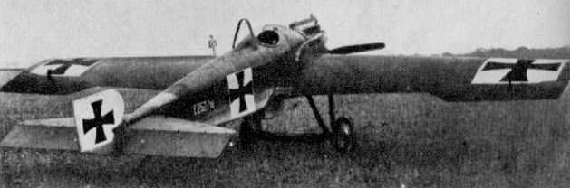
Junkers J 2 252/16
Junkers J I
To succeed and supplement the interim A.E.G. and Albatros J types (which had been little more than modified C types) the Junkers J I arrived in the Infanterieflieger units in 1917. It should be noted that the factory designation of this machine was J 4. In the past this has often been confused with the military J I designation.
The J I was mainly the product of Dr. Hugo Junkers' fertile brain. Dr. Junkers had pioneered the construction of all-metal monoplanes in 1915, when he produced the 120 h.p. Mercedes-powered cantilever J 1. This was followed in 1916 with an extremely neat and modern-looking monoplane, designated J 2, of which several were built. These aircraft were technically superior in constructional technique to anything that was then flying, though somewhat under-powered. Notwithstanding, the German authorities were so impressed with his constructional methods that Junkers was asked by the Flugzeugmeisterei to produce an armoured biplane. The first machine was partly designed by Prof. Madelung, who originally wanted it to be a parasol. It was completed early in 1917 and was of unique format. Corrugated sheet covering was used, as opposed to the plain sheet metal of the earlier J 1 and J 2. The medium was no longer tinplate (Eisenblech - literally sheet iron), but an alloy riveted to a dural frame. This aircraft became the J I, and it may be noted that Anthony Fokker was in no way connected with the enterprise at this time; his association with Junkers was not until October 1917.
The unorthodox layout of the Junkers J I was comprised of a large upper and a small lower cantilever wing combined with a hexagonal-shaped fuselage, bestowing an angular yet curiously racy appearance. A completely armoured nose capsule of 5 mm. chrome-nickel sheet steel enclosed the engine and crew compartment, terminating in a solid bulkhead to give protection from immediately astern. To this was joined the rear half of the fuselage, consisting of an alloy tube frame which was fabric covered, although some of the last production machines had the corrugated skin. The tailplane and split elevators were of near rectangular shape. On the prototype a plain triangular fin and near rectangular-shaped, unbalanced rudder vas fitted, the fin being braced to the upper longerons by steel struts on either side. On production machines the fin was cut down in height and braced alternatively by a vee strut or a single strut on either side, and a horn balance portion was incorporated in the rudder, which was otherwise of parallelogram shape. Again the empennage was a dural-tube frame with corrugated covering.
Of vast proportions, the upper wing was in three roughly equal panels, the centre-section being of constant chord with a large semicircular cut-out. The outer panels had some 5" of sweep on the leading-edge only, and were rounded to graceful rake at the tips. Ailerons of constant chord extended the whole length of the outer panels, and on the prototype were unbalanced. On the production machines, however, a large overhung balance portion was added; the chord was also increased, which gave the trailing edge a cranked appearance. The lower wing was of the same profile but only about one-third the area of the upper wing. Construction of the wings was based on a series of tubular dural spars, as many as eleven at the full chord of the upper wing - five top surface, six bottom surface. To these were riveted tubular diagonals which spaced the spar tubes according to the depth of the required aerofoil section and, in effect, formed a Warren girder-type rib skeleton. When the corrugated 2 mm. dural skin was riveted to this basic framework it completed the triangulation of the rib structure and automatically assumed the desired aerofoil section. The upper wing was supported by four struts on each side, two springing from the bottom longerons and the other two from the lower wing, which was attached to a keel section underneath the fuselage. The lower wing was additionally braced to the bottom longerons by three short centre-section struts; this manner of a ring the wings gave the fuselage a slung appearance, as in the Bristol Fighter.
The undercarriage chassis consisted of three struts on each side, two springing from the centre of the lower wing and the third rising vertically from the apex of the other two to join the leading edge. The axle was sprung by being bound to the chassis with elastic shock cord. The only wooden part of the aircraft was the sturdy ash tailskid, which was hinged on an inverted pylon and internally sprung.
The Benz engine of some 200 h.p. was fitted with high-compression cylinders and was completely enclosed in the armoured capsule, with additional panels encowling the actual cylinder block. These upper panels of armour were hinged at their rear end and swung outwards to allow easy access to the engine for servicing A long narrow radiator was fixed under the centre-section directly in the slipstream. On the earlier production models a vertical-type exhaust manifold curved back towards the top wing, but this was later replaced by a straightforward upright manifold. Most J Is were equipped with a large spinner which certainly helped to soften the angularity of the general lines, but these were frequently removed in the field.
All flight controls were positively operated by direct linkage through a system of cranks and control push-rods, all enclosed within the airframe, and nowhere in the control system were cables used at all. This made for much greater invulnerability to small-arms fire from the ground, to which the J Is were continually subjected.
The Junkers J I began to equip the Ft. Abt. (Inf.) units towards the end of 1917. Once crews had adapted themselves to this revolutionary aeroplane they viewed it with considerable favour, welcoming the measure of protection its armour afforded. Although heavy, cumbersome and difficult to land and take-off from rough ground, the J Is were immensely strong and well suited to their contact patrol duties, which consisted primarily of establishing the course of the Front Line and its alterations. All work was done at low altitude, and usually the observer reported the position to the rear command post by radio, although quite often message bags were dropped. Certainly these reports were the most reliable sources of news to the commanders in battle. Infantry co-operated with the aircraft by laying out cloth-strip ground signals or burning smoke flares to indicate their position. Ammunition and rations were dropped to machine-gun nests, trench systems and outposts that had been cut off and could not otherwise be supplied.
Armament of the J Is was conventional, comprising two synchronized Spandaus firing forward and a Parabellum machine-gun manually operated by the observer. The mounting of twin fixed downward-firing machineguns had been found unsatisfactory due to the impracticability of aiming at ground targets from a low height, owing to the aircraft's speed.
A total of 227 Junkers J Is was built.
TECHNICAL DATA
Description: Close support, armoured two-seater.
Manufacturer: Junkers Flugzeug-Werke A.G. Dessau. (Junk.).
Power Plant: One 200 h.p. Benz Bz IV 6 cylinder in-line water-cooled engine fitted high-compression cylinders.
Dimensions: Span, 160 m. (52 ft. 6 in.). Length, 91 m. (29 ft. 10 3/8 in.). Height, 3.4 m. (11 ft. 1 5/8 in.). Area, 49.4 sq.m. (533.52 sq.ft.).
Weights: Empty, 1,766 kg. (3,885 lb.). Loaded, 2,176 kg. (4,787.2 lb.).
Performance: Maximum speed, 155 km.hr. (96.875 m.p.h.). Climb, 2,000 m. (6,560 ft.) in 32 min. Endurance, ca. 2 hr.
Armament: Two fixed Spandau machine-guns forward and one manually operated Parabellum machine-gun in rear cockpit.

Junkers J I.
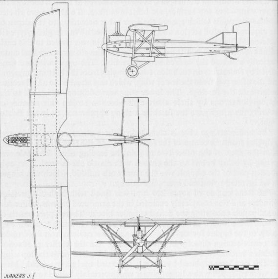
Junkers J 8
This two-seat prototype was developed into the J 10 which went into production as the CL I. There was little visual difference in the two types, and principal J 10 data applies.
Junkers J 10 (CL I)
Virtually a two-seat version of the D I, the CL I was put into production during the later half of 1918 with the intention of replacing the Halberstadt CL types, which were the mainstay of the Schlachtstaffeln. Again an all-metal machine, continuing the usual style of Junkers construction with corrugated dural covering, some forty-seven aircraft had been built by the end of the war. Engine, 180 h.p. Mercedes D IIIa. Span. 12.04 m. (39 ft. 6 in.). Length, 7.9 m. (25 ft. 11 1/8 in.). Height, 2.65 m. (7 ft. 8 1/2 in.). Area, 23.4 sq.m. (253 sq.ft.). Weights: Empty, 710 kg. (1,562 lb.). Loaded, 1,050 kg. (2,310 lb.). Speed, 161 km.hr. (100.625 m.p.h.). Climb, 1,000 m. (3.280 ft.) in 3.9 min. (type test February 1918 figures). Armament, twin fixed Spandau and one Parabellum machine-guns.
Junkers J 7
Built during 1917, this machine was the prototype for the later D.I. Several modified variants existed, the original J 7 did not have orthodox ailerons; instead each complete wing-tip was arranged to swivel. However, these sections were prone to flutter and did not give the pilot sufficient feel in the controls, so ailerons were eventually incorporated. Power plant was the 160 h.p. Mercedes D III, with radiator over cylinder block as illustrated; the modified J 7 with ailerons had a car-type radiate at the nose. The J 7 participated in the second D types Competition in June 1918, when it climbed to 5,000 m. (16,400 ft.) in 23.7 min. at loaded weight of 836 kg. (1,839 lb.).
Junkers J 9 (D I)
This single-seat fighter was ordered into production during 1918, but only a relative handful of machines got to the Front, for operational assessment, before the Armistice. The all-metal D I differed mainly from the J 7 prototype in having a fuselage some 1 ft. 10 in. greater in length and a 185 h.p. B.M.W. engine installed. It participated in the third D types Competition. Span, 9.0 m.(29 ft. 6 3/8 in.). Length,7.25m.(23ft. 9 3/8 in.). Height 2.25 m. (7 ft. 4 1/2 in.). Area, 14.8 sq.m. (159 sq.ft.). Weights: Empty, 654 kg. (1,439 lb.). Loaded, 834 kg. (1,835 lb.). Speed, 185 km.hr. (118.75 m.p.h.). Climb, 1,000 m. (3,280 ft.) in 2.3 min. Armament, twin-fixed Spandau machine-guns.
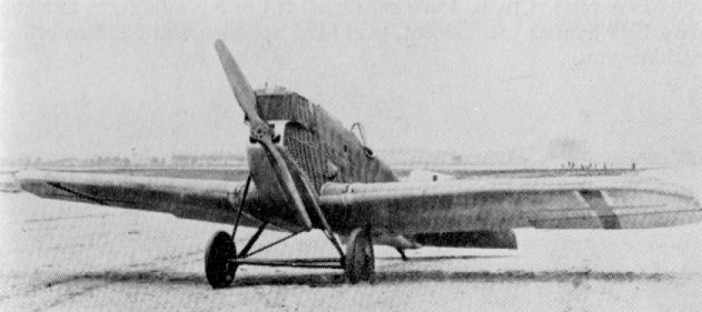
Junkers J 11 (CLS I)
Three machines (Nos. 7501-7503) which were literally seaplane versions of the CL I were delivered to the German Navy during 1918. Apart from the addition of a vertical fin to compensate the additional side area of the floats, the aircraft differed little from its landplane counterpart (apart from the obvious float chassis), although it was marginally larger in dimension. The tail surfaces were never really satisfactory, and after the war a completely new empennage was designed, when the type was used for civil purposes. Engine, 200 h.p. Benz. Span, 12.75 m. (41 ft. 10 in.). Length, 8.95 m. (29 ft. 4 3/8 in.). Height, 2.95 m. (9 ft. 8 1/8 in.). Weights: Empty, 914 kg. (2,011 lb.). Loaded, 1,420 kg. (3,124 lb.). Speed, 180 km.hr. (112.5 m.p.h.). Armament, twin Spandau and one Parabellum machineguns.
Three machines (Nos. 7501-7503) which were literally seaplane versions of the CL I were delivered to the German Navy during 1918. Apart from the addition of a vertical fin to compensate the additional side area of the floats, the aircraft differed little from its landplane counterpart (apart from the obvious float chassis), although it was marginally larger in dimension. The tail surfaces were never really satisfactory, and after the war a completely new empennage was designed, when the type was used for civil purposes. Engine, 200 h.p. Benz. Span, 12.75 m. (41 ft. 10 in.). Length, 8.95 m. (29 ft. 4 3/8 in.). Height, 2.95 m. (9 ft. 8 1/8 in.). Weights: Empty, 914 kg. (2,011 lb.). Loaded, 1,420 kg. (3,124 lb.). Speed, 180 km.hr. (112.5 m.p.h.). Armament, twin Spandau and one Parabellum machineguns.
K.W.
Various two-seater seaplanes were designed and built in ones and twos by the Imperial Naval Yards (Kaiserlicht Werft) as follows: Danzig: Nos. 404-405, 467-470, 1105-1106 and 1650. Kiel: Nos. 463-466. Wilhelmshafen: Nos. 401-403, 461-462, 945 and 947.
Various two-seater seaplanes were designed and built in ones and twos by the Imperial Naval Yards (Kaiserlicht Werft) as follows: Danzig: Nos. 404-405, 467-470, 1105-1106 and 1650. Kiel: Nos. 463-466. Wilhelmshafen: Nos. 401-403, 461-462, 945 and 947.
K.W.
Various two-seater seaplanes were designed and built in ones and twos by the Imperial Naval Yards (Kaiserlicht Werft) as follows: Danzig: Nos. 404-405, 467-470, 1105-1106 and 1650. Kiel: Nos. 463-466. Wilhelmshafen: Nos. 401-403, 461-462, 945 and 947.
Danzig: Data on Nos. 467-470: Engine, 150 h.p. Benz Bz III. Span, 15.68 m. (51 ft. 5 5/8 in.). Length, 9.1 m. (29 ft. 10 3/8 in.). Height, 3.67 m. (12 ft. 0 1/2 in.). Area, 52 sq.m. (562 sq.ft.). Weights: Empty, 1,063 kg. (2,339 lb.). Loaded, 1,632 kg. (3,690 lb.). Speed, 128 km.hr. (80 m.p.h.). Climb, 1,000 m. (3,280 ft.) in 150 min.
Data on Nos. 461-462: Engine, 150 h.p. Benz Bz III. Span, 14.9 m . (48 ft. 3/4 in.). Length, 9.5 m. (31 ft. 2 1/8 in.). Height, 3.9 m. (12 ft. 9 5/8 in.). Area, 52 sq.m. (562 sq.ft.). Weights: Empty, 1,016 kg. (2,235 lb.). Loaded, 1,585 kg. (3,487 lb.). Speed, 143 km.hr. (89.325 m.p.h.). Climb, 1,000 m. (3,280 ft.) in 10.7 min.
K.W.
Various two-seater seaplanes were designed and built in ones and twos by the Imperial Naval Yards (Kaiserlicht Werft) as follows: Danzig: Nos. 404-405, 467-470, 1105-1106 and 1650. Kiel: Nos. 463-466. Wilhelmshafen: Nos. 401-403, 461-462, 945 and 947.
Data on Nos. 1105-1106: Engine, 150 h.p. Benz III. Span, 14.1 m. (46 ft. 3 1/4 in.). Length, 8.85 m. (29 ft. 0 3/8 in.). Height, 3.725 m. (12 ft. 2 5/8 in.).
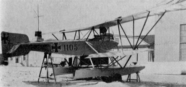
K.W. (Danzig)
K.W.
Various two-seater seaplanes were designed and built in ones and twos by the Imperial Naval Yards (Kaiserlicht Werft) as follows: Danzig: Nos. 404-405, 467-470, 1105-1106 and 1650. Kiel: Nos. 463-466. Wilhelmshafen: Nos. 401-403, 461-462, 945 and 947.
Various two-seater seaplanes were designed and built in ones and twos by the Imperial Naval Yards (Kaiserlicht Werft) as follows: Danzig: Nos. 404-405, 467-470, 1105-1106 and 1650. Kiel: Nos. 463-466. Wilhelmshafen: Nos. 401-403, 461-462, 945 and 947.
K.W.
Various two-seater seaplanes were designed and built in ones and twos by the Imperial Naval Yards (Kaiserlicht Werft) as follows: Danzig: Nos. 404-405, 467-470, 1105-1106 and 1650. Kiel: Nos. 463-466. Wilhelmshafen: Nos. 401-403, 461-462, 945 and 947.
Data on Nos. 1105-1106: Engine, 150 h.p. Benz III. Span, 14.1 m. (46 ft. 3 1/4 in.). Length, 8.85 m. (29 ft. 0 3/8 in.). Height, 3.725 m. (12 ft. 2 5/8 in.).
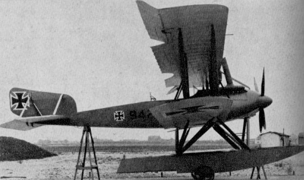
K.W. (Wilhelmshafen) (No. 947) (1917)
Kondor Taube Type H
Used, as were most Taube types, for unarmed reconnaissance and scouting duties, the Type H was built in 1915 and as such was the last Taube type constructed. The cut-out in the wing root was to facilitate observation. Engine, 100 h.p. Mercedes D I. Span, 13.5 m. (44 ft. 3 5/8 in.).
Used, as were most Taube types, for unarmed reconnaissance and scouting duties, the Type H was built in 1915 and as such was the last Taube type constructed. The cut-out in the wing root was to facilitate observation. Engine, 100 h.p. Mercedes D I. Span, 13.5 m. (44 ft. 3 5/8 in.).
Kondor W 1
Appearing in the spring of 1915, this machine was a conventional two-seater with a plywood-covered fuselage. Its interplane bracing was an unusual feature in that the two pairs of struts converged to form a vee when seen in the front view. Engine, 120 h.p. Mercedes D II. Span, 130 m. (42 ft. 7 1/8 in.). Length, 7.95 m. (26 ft. 1 in.). Area, 35 sq.m. (378 sq.ft.). Weight: Loaded 900 kg. (1,980 lb.).
Kondor W 2 C
This design flew in the spring of 1916 and is on record as being the first aircraft to be fitted with the 220 h.p. Mercedes D IV "straight-eight" geared engine. No other details.
Kondor B I
Built for training duties with a large communal cockpit, the Kondor B I was type tested in January 1918. It was a conventional two-bay biplane of wooden construction with a ply-covered fuselage. Large "ear"-type radiators were accommodated on the fuselage sides, and ailerons were fitted at all four wingtips to afford sensitive lateral control. This aircraft pioneered the principles of simple construction: minimum number of parts needed, interchangeability of components and some pre-fabrication. Engine, 120 h.p. Mercedes D II. Weights: Empty, 806 kg. (1,773 lb.). Loaded, 1,150 kg. (2,530 lb.).
Built for training duties with a large communal cockpit, the Kondor B I was type tested in January 1918. It was a conventional two-bay biplane of wooden construction with a ply-covered fuselage. Large "ear"-type radiators were accommodated on the fuselage sides, and ailerons were fitted at all four wingtips to afford sensitive lateral control. This aircraft pioneered the principles of simple construction: minimum number of parts needed, interchangeability of components and some pre-fabrication. Engine, 120 h.p. Mercedes D II. Weights: Empty, 806 kg. (1,773 lb.). Loaded, 1,150 kg. (2,530 lb.).
Kondor D I
Designed by Rethel and Ehrhardt the Kondor D I appeared in the spring of 1918. The wing arrangement followed that of the Albatros, with single-spar lower wing and vee interplane struts. Engine, 110 h.p. Oberursel U II rotary. The D I participated in the second D types Competition in June 1918 at a loaded weight of 568 kg. (1,250 lb.); it climbed to 5,000 m. (16,400 ft.) in 30.6 min.
Kondor D II
A contemporary development of the D I, the D II differed principally in having a more conventional wing structure, and was fitted with ailerons at all four tips, those on the upper wing being balanced. Also competing in the second D types Competition, the D II climbed to 5,000 m. (16,400 ft.) in 33.1 min. at a loaded weight of 554 kg. (1,218 lb.). Engine, 110 h.p. Oberursel U II. Span, 7.59 m. (24 ft. 10 7/8 in.). Length, 4.86 m. (15 ft. 11 1/2 in.). Height, 2.41 m. (7 ft. 10 7/8 in.). Area, 13.3 sq.m. (144 sq.ft.). Weights: Empty, 370 kg. (814 lb.). Loaded, 550 kg. (1,210 lb.). Speed, 170 km.hr. (106.25 m.p.h.). Note unusual painting of cross on fin instead of on the rudder.
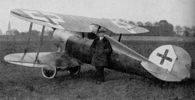
Kondor D II. Co-designer Rethel is standing beside the aircraft.
Kondor D 6
Further development of the D II with an unusual completely cut-out centre-section which sought to achieve maximum pilot visibility. The fuselage was of steel lube and fabric covered and not ply-skinned as it was in the D I and D II. Engine, 140 h.p. Oberursel U III. Span, 8.25 m. (27 ft. 0 3/4 in.). Length, 5.8 m. (19 ft. 0 3/8 in.). Height, 2.53 m. (8 ft. 3 5/8 in.). Area, 13.8 sq.m. (149 sq.ft.). Weights: Empty, 420 kg. (924 lb.). Loaded, 645 kg. (1,419 lb.).
Further development of the D II with an unusual completely cut-out centre-section which sought to achieve maximum pilot visibility. The fuselage was of steel lube and fabric covered and not ply-skinned as it was in the D I and D II. Engine, 140 h.p. Oberursel U III. Span, 8.25 m. (27 ft. 0 3/4 in.). Length, 5.8 m. (19 ft. 0 3/8 in.). Height, 2.53 m. (8 ft. 3 5/8 in.). Area, 13.8 sq.m. (149 sq.ft.). Weights: Empty, 420 kg. (924 lb.). Loaded, 645 kg. (1,419 lb.).
Kondor D 7
Appearing late in 1917, the single-seat lighter D 7 bore unmistakable signs of Albatros influence, although design of the machine is credited to Westphal. Bracing of the wing cellule was novel, as was also the slinging of the ply-skinned fuselage between the wings. The extremely robust undercarriage chassis was attached to the main longerons, which were in the vertical and horizontal centre-line planes. The fuselage, with underslung lower wing, evolved from an earlier triplane design which was a failure. The D 7 also failed to come up to expectation. Engine, 160 h.p. Mercedes D III. Span, 8.5 m. (27 ft. 10 3/4 in.). Length. 6.2 m. (20 ft. 4 1/8 in.). Height, 2.3 m. (7 ft. 6 1/2 in.). Area, 15.7 sq.m. (169.5 sq.ft.). Weights: Empty, 590 kg. (1,298 lb.). Loaded, 785 kg. (1,727 lb.).
Appearing late in 1917, the single-seat lighter D 7 bore unmistakable signs of Albatros influence, although design of the machine is credited to Westphal. Bracing of the wing cellule was novel, as was also the slinging of the ply-skinned fuselage between the wings. The extremely robust undercarriage chassis was attached to the main longerons, which were in the vertical and horizontal centre-line planes. The fuselage, with underslung lower wing, evolved from an earlier triplane design which was a failure. The D 7 also failed to come up to expectation. Engine, 160 h.p. Mercedes D III. Span, 8.5 m. (27 ft. 10 3/4 in.). Length. 6.2 m. (20 ft. 4 1/8 in.). Height, 2.3 m. (7 ft. 6 1/2 in.). Area, 15.7 sq.m. (169.5 sq.ft.). Weights: Empty, 590 kg. (1,298 lb.). Loaded, 785 kg. (1,727 lb.).
Kondor E III and IIIa
A parasol monoplane in two versions was designed by Rethel and Ehrhardt to participate in the third D types Competition in October 1918. The E III was fitted with 140 h.p. Oberursel U III engine and had a cut-away horse-shoe-type cowling; the E IIIa (above) had the 200 h.p. Goebel IIIa, which was enclosed in a circular cowling with louvred vents all round it. Engine, 140 h.p. Oberursel U III (E IIIa), 200 h.p. Goebel IIIa (E IIIa). Span, 9 0 m. (29 ft. 6 3/8 in.). Length, 5.8 m. (19 ft. 0 3/8 in.). Height, 2.745 in. (9 ft. 0 in.). Area, 12.4 sq.m. (134 sq.ft.). Weights: Empty, 465 kg. (1,023 lb.). Loaded, 660 kg. (1,452 lb.). Speed, 195 km.hr. (121.875 m.p.h.), E III; 200 km.hr. (125 m.p.h.), E IIIa. Climb. 5,000 m. (16,400 ft.), 16 min. E III; 11 min. E IIIa.
A parasol monoplane in two versions was designed by Rethel and Ehrhardt to participate in the third D types Competition in October 1918. The E III was fitted with 140 h.p. Oberursel U III engine and had a cut-away horse-shoe-type cowling; the E IIIa (above) had the 200 h.p. Goebel IIIa, which was enclosed in a circular cowling with louvred vents all round it. Engine, 140 h.p. Oberursel U III (E IIIa), 200 h.p. Goebel IIIa (E IIIa). Span, 9 0 m. (29 ft. 6 3/8 in.). Length, 5.8 m. (19 ft. 0 3/8 in.). Height, 2.745 in. (9 ft. 0 in.). Area, 12.4 sq.m. (134 sq.ft.). Weights: Empty, 465 kg. (1,023 lb.). Loaded, 660 kg. (1,452 lb.). Speed, 195 km.hr. (121.875 m.p.h.), E III; 200 km.hr. (125 m.p.h.), E IIIa. Climb. 5,000 m. (16,400 ft.), 16 min. E III; 11 min. E IIIa.
L.F.G. Roland C II
Luftfahrzeug Gesellschaft (L.F.G.) was the successor of the Flugmaschine Wright G.m.b.H., an offspring of the L.F.G. Bitterfeld, which, in turn, had stemmed from the Motorluftschiff Studiengesellschaft founded for airship manufacture at the instigation of Wilhelm II in 1906. The Wright firm at Adlershof went into liquidation in 1912 after losing their patents claim. The firm was then revived by Krupp and other financiers for the manufacture of aircraft, as L.F.G, with Herr Kiefer as chief engineer. It was then that "Roland" was registered as a trade name to avoid confusion with the L.V.G. firm. The factory at Adlershof was gutted by fire on 6th September 1916, due, it is said, to action by the British Secret Service. The factory was then transferred to the exhibition halls at Charlottenburg, where manufacture continued.
One of the most original trends of thought in aircraft design during 1915 was seen in the L.F.G. Roland C II, which had been evolved by Dipl. Ing. Tantzen, who had recently joined Luftfahrzeug Gesellschaft as a design engineer. Earlier the Albatros B I, B II and C I (Rol), which so patently typified current thought on two-seat reconnaissance machines, had been license-built by L.F.G.
Tantzen's ambition was to present a drastically cleaned-up airframe, eliminating as much as possible of the "built-in" drag of interplane, centre-section strut arrangements and attendant bracing. He employed a deep fuselage which had the two-fold objective of eliminating the drag of centre-section struts and, by joining the top wing direct to the fuselage, presenting the crew with an unparalleled all-round field of view. There was some restriction of downward view, but cut-outs in the wing roots and the arrangement of the stagger mitigated this. A further refinement was the simplification of the bracing to a single-bay format and the utilisation of single I-type interplane struts.
An interesting fact about the Roland C II is that the designer foresaw that the deep fuselage might precipitate difficulty in ensuring adequate control, and a series of experiments was conducted with the airframe mounted on a flat-topped railway wagon. Fast runs were made over a long, straight stretch of track between Schoneberg and Juterbog. The prototype appeared in October 1915 and was lost due to engine failure, but a second machine soon under test, and it was found necessary to revise the originally triangular-shaped horizontal fins. Still later it was found that the machine lacked directional stability, tending to hunt and demanding constant vigilance from the pilot; subsequent increase in the vertical fin area improved this shortcoming. The main deficiency of the C II was that the very thin wings tended to distort after any length of time on active service and the climb performance became very poor.
C IIs began to equip the Fl. Abt. units for reconnaissance and also for escort duties by the beginning of 1916. Usually the reconnaissance machines were armed only with a Parabellum gun for the observer, and a radio transmitter also formed part of his equipment. Later a forward-firing Spandau gun was added to the armament.
Eduard von Schleich, who later became well known as C.O. of one of the Bavarian Jagdstaffeln, for a time flew these Roland two-seaters when with Fl. Abt. 4. Frequently C IIs operated in considerable numbers, the reconnaissance machines being protected by the escorts. Capt. Albert Ball, V.C., often reported combats with large numbers of Rolands during the Battle of the Somme in the summer of 1916. Ball's first officially confirmed victory in fact over a Roland C II. Flying a Nieuport scout in company with four F.E. 8s during the late afternoon of the 2nd July, a formation of six Rolands was attacked at 10,000 ft. Immediately the German formation broke up, but after briefly manoeuvring for a favourable position to attack, Ball was able to put in a whole drum of Lewis at almost full deflection. The two-seater was seen to crash on the Mercatel-Arras road, and confirmation subsequently given by a Vickers Gunbus crew which happened to be in the vicinity.
The story is told, probably apocryphal, that when the officials attended upon the trials of the C II one member was heard to remark, "Truly this machine is a whale!" and the type certainly became unofficially known as the Walfisch.
Construction of the fuselage represented a revolutionary departure from standard practice, and was one of the first semi-monocoque structures. The shell was built up on a basic skeleton of ply formers and longerons, with main "key" formers positioned fore and aft of the pilot's cockpit. To this was pinned and glued the thin three-ply covering, which was applied in narrow strips and spirally wound on to the basic frame; this in turn was covered with linen fabric and doped. The root attachment fairings for both upper and lower wings were built integral with the fuselage. The 160 h.p. Mercedes D III engine was almost completely buried in the deep nose, only the first two cylinders being partially exposed. The exhaust pipes were led mostly into an occarina-shaped manifold, and "ear" type radiators were located on the fuselage sides just aft of the engine. Only the section of the fuselage immediately aft of the large spinner was of metal panelling, and this was generously slotted with cooling vents. Hinged metal access panels were fitted where necessary to facilitate servicing. In the vicinity of the cockpit were large celluloid-covered panels which considerably improved visibility. However, it is doubtful if they were large enough to serve as escape hatches, as has often been claimed. The pylon on the centre-section was a safeguard against decapitation of the crew in the event of a capsized crash-landing.
Of composite construction, the empennage featured wooden, fabric-covered fins, while the unbalanced control surfaces were of steel tube with fabric covering. When later the area of the vertical fin was increased it was braced to the tailplane with two light steel struts in addition to the usual struts underneath.
Construction of the wings was orthodox in that they were based on two hollow box-spars - with the rear (main) spar at approximately mid-chord - and three steel-tube compression members to each panel. Ribs were of ply webs, with softwood capping and reinforcing strips. They were interspersed with false ribs, which extended right back to the rear spar. All four panels were of identical span and chord, with angularly raked tips and wire trailing edges which gave the characteristic scalloped profile. The unbalanced ailerons were inversely tapered, and their oblique mounting preserved the straight trailing edge. They were of steel tube construction: actuation was through cables attached to a crank and connected to a torque tube which ran through the forward edge of the lower wing. In a later model this torque tube ran through the top wing. The unique I interplane struts were covered with a double layer of three-ply and connected all four wing spars in ball-and-cup joints.
The conventional undercarriage chassis consisted of streamline steel-tube vees with tubular axle and twin spreader bars. Wheels were sprung with elastic shock cord. On aircraft fitted with radio an airscrew-driven dynamo was attached to the top of the front starboard undercarriage strut. A large hockey-stick type tailskid of ash completed the landing gear.
Although exact figures are not known, several hundred C IIs were built, and the type was also manufactured under licence by the Linke-Hofmann concern.
TECHNICAL DATA
Description: Two-seat reconnaissance and escort duties.
Manufacturers: Luftfahrzeug Gesellschaft m.b.H. Berlin-Charlottenburg (Rol.).
Sub-contractors: Linke-Hofmann Werke A.G. (Li.).
Power Plant: One 160 h.p. Mercedes D III 6 cylinder in-line water-cooled engine.
Dimensions: Span, 10.3 m . (33 ft. 9 1/2 in.). Length, 7.7 m. (25 ft. 3 1/4 in.). Height, 2.9 m. (9 ft. 6 1/8 in.). Area, 26 sq.m. (280.8 sq.ft.).
Weights: Empty, 764 kg. (1,680.8 lb.). Loaded, 1,284 kg. (2,824.8 lb.).
Performance: Maximum speed, 165 km.hr. (103.12 m.p.h.). Climb, 1,000 m. (3,280 ft.) in 6 min., 2,000 m. (6,560 ft.) in 12 min., 4,000 m. (13,120 ft.) in 45 min. Duration, 4-5 hr. according to fuel load carried.
Armament: One manually operated Parabellum machine-gun in rear cockpit. Later a Spandau machine-gun firing forward was additionally fitted.
L.F.G. Roland C III
Development of C II Walfisch with orthodox two-bay wings. All-wooden aircraft with ply-covered fuselage. This machine existed as a prototype only and was destroyed when the Adlershof factory was burnt out on 16th September 1916. Engine, 200 h.p. Benz Bz IV. Armament, one Spandau and one Parabellum machine-guns.

A well-decorated L.F.G. Roland C IIa.
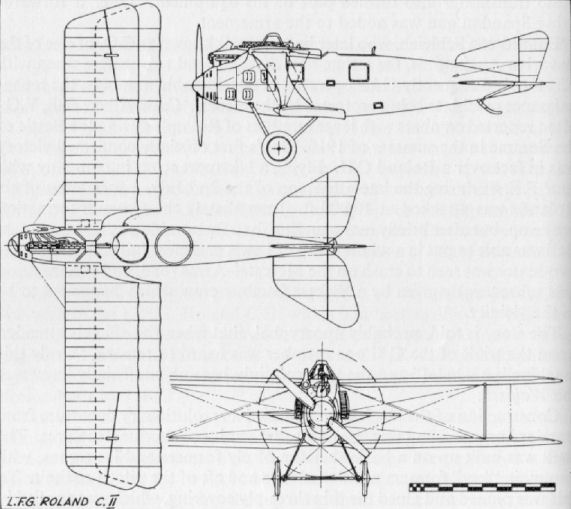
L.F.G. Roland G I
Although designated a G type, which covered twin-engined aircraft, the Roland G I was in fact a single-engined machine with twin pusher airscrews. The engine was buried in the fuselage on the centre of gravity and the airscrews driven through a system of gears and shafts. Only the single prototype, which carried a crew of two, was built. The extra thick tyres of the undercarriage were a noteworthy feature. Engine, 245 h.p. Maybach Mb IV. Span, 30.1 m. (98 ft. 9 1/4 in.). Length 15.9 m. (52 ft. 2 1/8 in.). Weights: Empty, 2,750 kg. (6,050 lb.). Loaded, 4,300 kg. (9,460 lb.). Speed, 160 km.hr. (100 m.p.h.). Armament, one Parabellum machine-gun.
Although designated a G type, which covered twin-engined aircraft, the Roland G I was in fact a single-engined machine with twin pusher airscrews. The engine was buried in the fuselage on the centre of gravity and the airscrews driven through a system of gears and shafts. Only the single prototype, which carried a crew of two, was built. The extra thick tyres of the undercarriage were a noteworthy feature. Engine, 245 h.p. Maybach Mb IV. Span, 30.1 m. (98 ft. 9 1/4 in.). Length 15.9 m. (52 ft. 2 1/8 in.). Weights: Empty, 2,750 kg. (6,050 lb.). Loaded, 4,300 kg. (9,460 lb.). Speed, 160 km.hr. (100 m.p.h.). Armament, one Parabellum machine-gun.
L.F.G. Roland C III
Development of C II Walfisch with orthodox two-bay wings. All-wooden aircraft with ply-covered fuselage. This machine existed as a prototype only and was destroyed when the Adlershof factory was burnt out on 16th September 1916. Engine, 200 h.p. Benz Bz IV. Armament, one Spandau and one Parabellum machine-guns.
Development of C II Walfisch with orthodox two-bay wings. All-wooden aircraft with ply-covered fuselage. This machine existed as a prototype only and was destroyed when the Adlershof factory was burnt out on 16th September 1916. Engine, 200 h.p. Benz Bz IV. Armament, one Spandau and one Parabellum machine-guns.
L.F.G. Roland D I
The D I of 1916 was built in small numbers until superseded by the D II /D IIa. It was very similar in size and construction to the later machine, differing mainly in the less-powerful motor and its attendant "ear"-type radiators. Engine, 100 h.p. Mercedes D I. Although not confirmed, dimensional data probably closely approximated that of D II. Armament, probably only one fixed Spandau machine-gun.
The D I of 1916 was built in small numbers until superseded by the D II /D IIa. It was very similar in size and construction to the later machine, differing mainly in the less-powerful motor and its attendant "ear"-type radiators. Engine, 100 h.p. Mercedes D I. Although not confirmed, dimensional data probably closely approximated that of D II. Armament, probably only one fixed Spandau machine-gun.
L.F.G. Roland D II and IIa
With the success of the Roland C II and quantity production established, thought was given by the L.F.G. design staff, led by Dipl. lng. Tantzen, to the production of a single-seater to a similar formula. The resultant aircraft, the L.F.G. Roland D I, first flown in July 1916, had an unmistakable resemblance to its forebear, although its lines were finer and its general appearance was much slimmer, which, without doubt, gave rise to the name it was given - "Haifisch" (Shark).
As in the C II, the fuselage encompassed the full depth of the gap, but the attachment of the upper wing panels was modified from the shoulder position to a central one, where they joined a low extruded pylon. Some revision of the tail surfaces, with the addition of a blister fin round the tail skid; further cleaning up of the centre-section attachment and replacement of the "ear"-type radiators, brought forth the D II, which first flew in October 1916.
Power unit of both the D I and D II was the 160 h.p. Mercedes D III. Alternative installation of the Argus As III of 180 h.p. in the D II airframe produced the D IIa; there were other minor modifications, mainly in the lightening of the structure. Engines were well buried in the nose, only the upper part of the foremost cylinders protruding above the fuselage shell. Twin Spandau machine-guns were positioned either side of the engine inside the fuselage, and collector manifolds were fitted on the starboard side of the motor exhausting sideways. A large, near hemispherical, metal spinner enclosed the propeller hub, and immediately aft of the airscrew was a metal cowling band extending the full diameter of the fuselage and slotted with characteristic Roland cooling vents. The remainder of the fuselage, with the exception of the metal engine-access panels, was of wooden construction based on very light oval plywood formers with spruce longerons, and spirally wrapped with a double three-ply skin only 1.5 mm. thick, which, in turn, was fabric covered. The vertical fin was also of wooden construction, built integral with the fuselage and surfaced with a plywood skin. Attachment of the wooden trapezoidal-shaped tailplane was unique. The inboard ends of the leading edge were hollowed and embedded on the ends of a timber member which transversed the fuselage and projected about 18 in. either side, thereby ensuring a rigid fixture. Additionally the tailplane was braced to the fin with two light streamlined steel struts. The horn-balanced control surfaces were of steel tube framing with fabric covering.
In the cable-braced wing structure, which was quite conventional, a return made to the more orthodox type of parallel interplane struts, as compared with the C IIs I-struts. The unstaggered wings were of equal chord, the upper of slightly greater span than the lower; they were rigged without dihedral, but had some 1 1/2 ° of sweep. There was only a slight rake to the almost square-cut tips. Based on the usual twin-spar arrangement, the spars were of hollow box construction and braced with four steel-tube compression members to each panel. The ply ribs were fretted with lightening holes and capped with ash flanges. False ribs were positioned between the main ribs and extended as far aft as the rear spar. Fabric-covered ailerons were unbalanced, of parallel chord and actuated by torque tubes running through the wings, which, in turn, were operated by push-rods connected to cranks at the inboard ends. The radiator of aerofoil shape was positioned centrally in the centre-section, and a gravity fuel tank was offset to port in the upper wing panel.
A conventional undercarriage chassis with streamline steel-tube vees was fitted. The axle and twin spreader bars were enclosed in a streamline fairing and the wheels were sprung with elastic cord.
Although cut-outs were made in the upper wing panels, forward view from the cockpit was very poor, a serious disadvantage in a fighter. Despite this, some 300 of the type (including D Is) were eventually built. The majority of these aircraft were constructed under licence by the Pfalz Flugzeug-Werke and not by the parent L.F.G. firm.
In an endeavour to improve forward view, the Roland D III was developed with a conventional centre-section, but saw only limited production, as it was already outclassed by other manufacturers' products. Roland D II and IIas did not usually form the complete establishment of any Jagdstaffeln when they came into service in the early months of 1917. Most seem to have appeared on the French sector of the Western Front, as they do not feature in British combat reports. Several D IIs were on the establishment of Jasta 27 at the time it was commanded by Hermann Goring during 1917 one being regularly flown by Lt. Karl Riehm. One unit that was completely equipped with Roland D IIs in 1917 was Marine Feldjagdstajfel 2. This unit was subsequently destroyed by a British bombardment, whereupon the Staffel was re-equipped with Alb. D IIIs. Jasta 25 in the Balkans in 1917 was also equipped with D IIs prior to receiving Albatroses.
Although having considerable speed, the Roland D IIs were not popular aircraft due to the heaviness of the controls, a considerable disadvantage in a fighter type.
TECHNICAL DATA
Description: Single-seat fighting scout.
Manufacturers: Luftfahrzeug Gesellschaft m.b.H. Berlin-Charlottcnburg (Rol.).
Sub-contractors: Pfalz Flugzeug-Werke G.m.b.H. Speyer am Rhein (Pfal.).
Power Plant:
One 160 h.p. Mercedes D III six cylinder in-line water-cooled engine (D II.)
One 180 h.p. Argus As III six cylinder in-line water-cooled engine (D IIa.)
Dimensions:
Span, 8.94 m. (29 ft. 4 in.). Length, 693 m. (22 ft. 8 7/8 in.). Height, 3.11 m. (10 ft. 2 3/8 in.). Area, 22.8 sq m. (246.25 sq.ft.). (D II.)
Span, 8.9 m. (29 ft. 2 1/2 in.). Length, 6.95 m. (22 ft. 9 5/8 in.). Height, 2.95 m. (9 ft. 8 1/8 in.). Area, 22 sq.m. (237.6 sq.ft.). (D IIa.)
Weights:
Empty, 715 kg. (1,573 lb.). Loaded, 954 kg. (2,098.8 lb.). (D II.)
Empty, 635 kg. (1,397 lb.). Loaded, 795 kg. (1,749 lb.). (D IIa.)
Performance: Maximum speed, 170 km.hr. (105 m.p.h.). Climb, 5,000 m. (16,400 ft.) in 23 min., D II; 5,000 m. (16,400 ft.) in 20 min., D IIa.
Armament: Two fixed Spandau machine-guns firing forward.
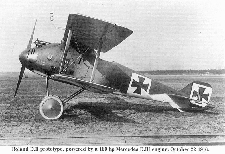
L.F.G. Roland D II prototype, powered by a 160 hp Mercedes D.III engine, October 22 1916.
Improved forward and downward view from the cockpit was offered by the Roland D II.
Improved forward and downward view from the cockpit was offered by the Roland D II.
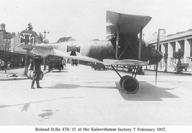
Roland D IIa 478/17 at the Kaiserdamm factory 7 February 1917.
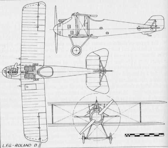
L.F.G. W
Only a single example of the L.F.G. W two-seat reconnaissance seaplane was built, No. 509. It was little more than a modified Albatros C Ia airframe (which machine L.F.G. built under licence) mounted on a float chassis. The floats themselves were unusual in being of basically cylindrical shape with two deep built-on steps. Seaplanes were built at the L.F.G. Bitterfeld plant and did not bear Roland trade mark. Engine, 150 h.p. Benz Bz III.
Only a single example of the L.F.G. W two-seat reconnaissance seaplane was built, No. 509. It was little more than a modified Albatros C Ia airframe (which machine L.F.G. built under licence) mounted on a float chassis. The floats themselves were unusual in being of basically cylindrical shape with two deep built-on steps. Seaplanes were built at the L.F.G. Bitterfeld plant and did not bear Roland trade mark. Engine, 150 h.p. Benz Bz III.
L.F.G. Roland C V
This 1917 two-seater was based upon the D II design as is apparent from the arrangement of the centre-section pylon. Only a single prototype was built. Engine, 160 h.p. Mercedes D III. Armament, one Spandau and one Parabellum machine-guns.
L.F.G. Roland C VIII
This rather ponderous-looking aircraft was the last L.F.G. original design two-seater. It stemmed from the C III, but remained no more than a prototype, as the firm was called upon to build the Albatros C X under licence. Engine, 260 h.p. Mercedes D IVa or 245 h.p. Maybach Mb IV. Armament, one Spandau and one Parabellum machine-guns.
L.F.G. Roland D III
Produced and type tested in October 1916, the D III was intended to succeed the D IIa in service, but no great number was built due to increased production of the superior Albatros lighters. The D III continued the all-wooden construction with ply-covered fuselage, differing from its forebears principally in having reduced chord on the lower wings, resulting in converging interplane struts and the wing carried on conventional centre-section struts. Engine, 180 h.p. Argus As III. Weights: Empty, 717 kg. (1,577 lb.). Loaded, 961 kg. (2,114 lb.). Armament, twin fixed Spandau machine-guns.
Produced and type tested in October 1916, the D III was intended to succeed the D IIa in service, but no great number was built due to increased production of the superior Albatros lighters. The D III continued the all-wooden construction with ply-covered fuselage, differing from its forebears principally in having reduced chord on the lower wings, resulting in converging interplane struts and the wing carried on conventional centre-section struts. Engine, 180 h.p. Argus As III. Weights: Empty, 717 kg. (1,577 lb.). Loaded, 961 kg. (2,114 lb.). Armament, twin fixed Spandau machine-guns.
L.F.G. Roland D IV
Built in 1917, this elegant triplane was the first L.F.G. single-seater to feature the clinker-built fuselage which is described in the main text under L.F.G. D VIb. All control surfaces were unbalanced, and ailerons were fitted to both upper and lower wings. The tailplane was adjustable for incidence, but not during flight. Engine, 160 h.p. Mercedes D III.
Built in 1917, this elegant triplane was the first L.F.G. single-seater to feature the clinker-built fuselage which is described in the main text under L.F.G. D VIb. All control surfaces were unbalanced, and ailerons were fitted to both upper and lower wings. The tailplane was adjustable for incidence, but not during flight. Engine, 160 h.p. Mercedes D III.
L.F.G. Roland D V
Following the original triplane D IV, the L.F.G. D V was a development of the D III and in fact utilised the complete wing cellule of that type. The same type of ply-skinned, semi-monocoque fuselage was used although considerably lined down to slimmer proportions. Only the single prototype was built. Engine, 160 h.p. Mercedes D III.
Following the original triplane D IV, the L.F.G. D V was a development of the D III and in fact utilised the complete wing cellule of that type. The same type of ply-skinned, semi-monocoque fuselage was used although considerably lined down to slimmer proportions. Only the single prototype was built. Engine, 160 h.p. Mercedes D III.
L.F.G. WD
This single-seat seaplane was developed from the D I and intended as a station defence machine. It first flew on 29th June 1917 and remained a solitary prototype. Engine, 160 h.p. Mercedes D III.
This single-seat seaplane was developed from the D I and intended as a station defence machine. It first flew on 29th June 1917 and remained a solitary prototype. Engine, 160 h.p. Mercedes D III.
L.F.G. Roland D IX (first version)
The first of three D IX prototypes, No. 3001/18, was fitted with 160 h.p. Siemens-Halske Sh III geared rotary engine. It competed in the second D types Competition in the summer of 1918. Span, 8.92 m. (29 ft. 3 1/8 in.). Area, 18.48 sq.m. (199.5 sq.ft.). Weights: Empty, 534 kg. (1,175 lb.). Loaded, 754 kg. (1,658 lb.). Climb, 5,000 m. (16,400 ft.) in 16.4 min., 6,000 m. (16,680 ft.) in 23 min. Armament, twin Spandau machine-guns.
L.F.G. Roland D IX (second version)
Differing from the first prototype, this second machine had much larger tail surfaces and unbalanced ailerons. Engine now installed was 210 h.p. Siemens-Halske IIIa. Armament, twin Spandau machine-guns.
L.F.G. Roland D IX (third version)
This third, and final, D IX prototype differed from the second machine in having a large horn-balanced rudder and overhung, balanced ailerons as on the first prototype. Engine, 210 h.p. Siemens-Halske IIIa geared rotary. Armament, twin Spandau machine-guns.
L.F.G. Roland D XIV
Powered with the 170 h.p. Goebel Goe IIIa eleven-cylinder rotary engine, the D XIV (No. 3003/18) was a development of the D IX. Span, 9.0 m. (29 ft. 6 3/8 in.). Area, 23 sq.m. (248 sq.ft.). Armament, twin Spandau machine-guns.
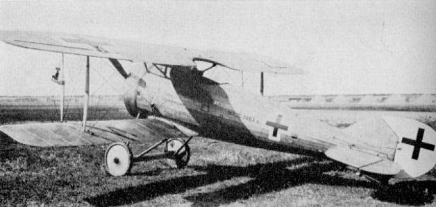
L.F.G. Roland D XIV
L.F.G. Roland D VI (prototype)
From this machine, the 1,000th Roland aeroplane built, was developed the successful D VIb production type. Engine, 160 h.p. Mercedes D III.
L.F.G. Roland D VIa (prototype)
Another of the Roland D VI prototypes, fitted with large horn-balanced rudder and overhung balanced ailerons. Engine, 160 h.p. Mercedes D III. Armament, twin Spandau machine-guns.
L.F.G. Roland D VIb (prototype)
Yet another D VI prototype. A standard D VIb fitted with two-bay wings and "I" interplane struts. Engine, 200 h.p. Benz IIIa. Armament, twin Spandau machine-guns.
L.F.G. Roland D VIa and VIb
First of a long line of some twelve L.F.G. Roland lighters, the D I appeared in 1916 and was developed through to the D V, but only the D II and IIa were built in any quantity. In the D VI series, which followed, the klinkerrumpf style of fuselage construction, first pioneered in the D IV triplane, was again used. The prototype D VI was the 1,000th Roland machine built, and differed from the production variant in having no under-fin and unbalanced ailerons. Various modifications, mainly in the tail surfaces, followed, including one aircraft with double bay I-struts in order to dispense with incidence bracing.
Produced to compete in the 1918 "fighter trials'" held at Adlershof, this elegant-looking aeroplane was first fitted with the 160 h.p. Mercedes D III engine, when it was known as the D VIa, but as supplies of this engine were restricted, it was reworked to take the Benz III of similar power. Although the main production order went to the Fokker D VII, an order was placed for a batch of Roland D VIs as a precaution against Fokker D VII supplies breaking down.
Distinctive features of the D VI were its "clinker"-built fuselage, keel-mounted lower wing and rather "droop snoot" nose. The proportions of the D VI were nicely balanced, and it was of distinctly clean and racy appearance: its performance was good, and it was probably only the somewhat intricate fuselage construction, and consequent production difficulties, that precluded the placing of a larger order.
The fuselage was "clinker" planked after the style of small boat construction. The slightly tapered strips of spruce were wedge-shaped in section and overlapped each other by some two-thirds, thereby giving a smooth internal surface. They were pinned and glued to the light basic structure of spruce longerons and ply formers.
The Benz Bz IIIa engine was cleanly installed, with easily removed metal panels in the immediate vicinity of the cylinder block and aft of the neatly spinnered airscrew. A saxophone-type manifold exhausted to starboard. The main and under fins were both integrally built with the fuselage and covered with plywood. The keel, to which the lower wing panels were fitted, was also part of the fuselage structure. A bucket seat was fitted in the cockpit, the cross bearers of which dropped into spaced slots to afford some degree of adjustment. The control column was of steel tube with a grip top, and had auxiliary throttle adjustment very similar to that of the Fokker Dr I. The main throttle quadrant was on the left-hand side of the cockpit.
A tailplane of inverted aerofoil section and trapezoidal shape carried ovoid steel-tube elevators: it appears that both balanced and unbalanced elevators were fitted. The rudder was also of steel-tube construction, and all these members were fabric covered.
The parallel chord, single-bay wings were based on the orthodox twin main spar formula with steel-tube compression members: the built-up ribs were interspersed with false ribs. The radiator, which conformed to the wing section, was installed in the centre-section, slightly offset to starboard. Ailerons were of welded steel-tube framework and actuated through torque tubes running through the upper wing, as in the Roland D II. Centre-section struts were a welded steel-tube structure flattened at the lower attachment ends, slotted into their fixtures and secured with a bolt. Interplane struts were of wood, and converged slightly, due to the closer spar spacing in the lower wing, which was of narrower chord than the top wing. Some 3° of dihedral was rigged into the lower wing only, the top wing being perfectly flat.
The undercarriage was a conventional vee type of steel tube. The axle and spreader bars were neatly enclosed in a light fairing, and the wheels were sprung with elastic shock cord. The ash tailskid was hinged to the under-fin and sprung at its top with a lashing of elastic cord.
Flight characteristics of the Roland D VI were normal; slight nose heaviness with engines throttled well down and slightly tail heavy at full throttle. Manoeuvrability was assessed above that of the average single-seater, Take-off run was short, and the machine could be landed very slowly, though the somewhat narrow track produced a tendency to pirouette. Visibility from the cockpit was very good, and its roominess afforded considerable freedom of movement for the pilot, which contributed largely to the elimination of blind spots.
Apart from limited use with Jagdstajfeln (mainly Jasta 23), the Roland D VI was issued to the German Navy for seaplane defence duties. Some furteen of these aircraft were found at Barge (the station set up for the defence of Wilhelmshafen) after the Armistice.
TECHNICAL DATA
Description: Single-seat fighter.
Manufacturer: Luftfahrzeug Gesellschaft m.b.H. Charlottenburg (Rol.).
Power Plant: One 200 h.p. Benz Bz IIIa 6 cylinder in-line water-cooled engine, (D VIb).
Dimensions: Span, 9.4m. (30 ft. 10 1/8 in.). Length, 6.322 m. (20ft. 8 3/4 in.). Height, 2.8 m. (9 ft. 2 1/4 in.). Area, 22.13 sq. m. (239 sq.ft.).
Weights: Empty, 650 kg. (1,450 lb.). Loaded, 860 kg. (1,892 lb.).
Performance: Maximum speed, 182.5 km.hr. (114 m.p.h.). Climb, 1,000 m. (3,280 ft.) in 2 1/2 min., 3,000 m. (9,840 ft.) in 9 min., 6,000 m. (19,680 ft.) in 28 min. Endurance, 2 hr.
Armament: Two fixed Spandau machine-guns firing forward.
N.B. Performance figures for a D VIb (with 200 h.p. Benz) tested in the U.S.A. after the war were:
Climb to 6,500 ft. in 6 1/2 min; speed 114 m.p.h.
Climb to 10,000 ft. in 11 1/2 min.; speed 108 m.p.h.
Climb to 15,000 ft. in 24 min.; speed 99 m.p.h.
Climb to 17,400 ft. in 38 1/3 min.; speed 90 m.p.h.; service ceiling, 19,000 ft.
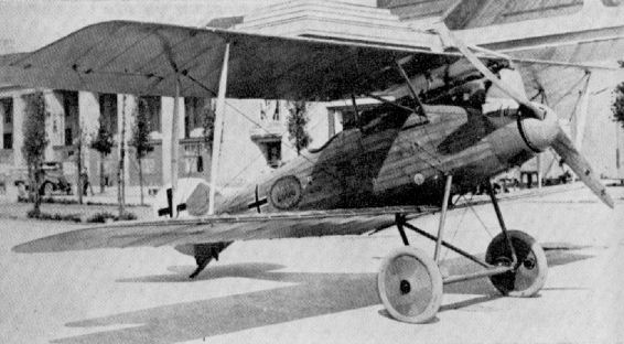
"Юбилейный" D.VI - двухтысячный аэроплан, построенный на фирме LFG.
L.F.G. Roland D Vlb.
L.F.G. Roland D Vlb.
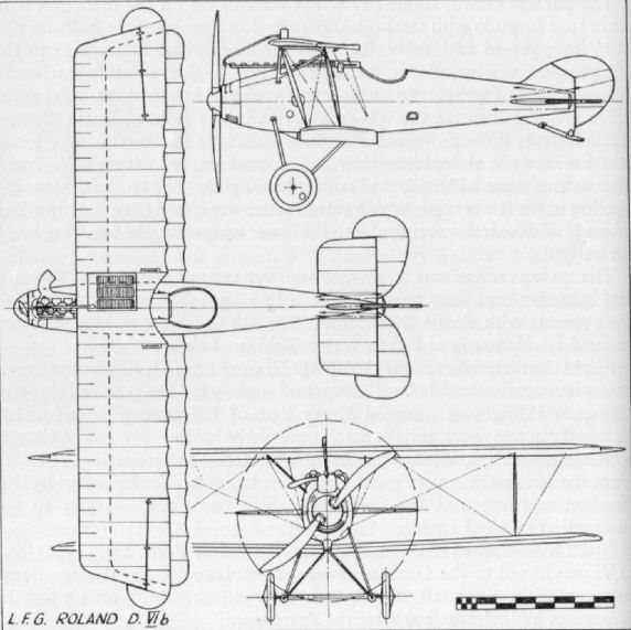
L.F.G. Roland D VII (first version)
First of the D VII prototypes (No. 224/18), this machine was fitted with 195 h.p. Benz IIIb direct-drive engine and participated in the second D types Competition in the summer of 1918. Span, 8.84 m. (29 ft. 0 in.) Area, 20.8 sq.m. (225 sq.ft.). Weights: Empty, 666 kg. (1,465 lb.). Loaded, 885 kg. (1,947 lb.). Climb, 5,000 m. (16,400 ft.) in 26.2 min. Armament, twin Spandau machine-guns.
L.F.G. Roland D VII (second version)
This second of the two D VII prototypes (No. 3910/18), was fitted with the high-speed 195 h.p. Benz IIIb m. engine, which had reduction gears to decrease airscrew speed and resulted in a more pointed nose. Tail surfaces were markedly different from the other prototype, as was also the shape and balance of the ailerons. Armament, twin Spandau machine-guns.

L.F.G. Roland D VII (second version)
L.F.G. Roland D XIII
Next in the long series of Roland prototypes was the D XIII serialled 3002/18, there being no record of D X, XI or XII. This was little more than the second version of the D VII with a 195 h.p. Korting vee-eight engine with reduction gearing. Span, 9 0 m. (29 ft. 6 3/8 in.). Area, 23 sq.m. (248 sq.ft.). Armament, twin Spandau machine-guns.
L.F.G. Roland D XV (first version)
As the first of four D XV prototypes, No. 3004/18 still perpetuated the use of clinker-built fuselage first used on the D IV. The wings had no bracing cables and considerably more stagger than any of the previous prototypes which probably improved forward and downward visibility from the cockpit, but omission of centre-section cut-out could not have given very good upward and forward field of view. Engine, 160 h.p. Mercedes D III. Span, 8.64 m. (28 ft. 4 1/4 in.). Area, 23.8 sq.m. (257 sq.ft.). Weights: Empty, 730 kg. (1,606 lb.). Loaded, 910 kg. (2,002 lb.). Armament, twin Spandau machine-guns.
L.F.G. Roland D XV (second version)
The second D XV prototype. No. 3006/18, was basically a D VI airframe with a new wing cellule braced solely with single I-struts, no cables being used. The top wing was of greater chord while the chord of the lower wing was considerably reduced. This was the last of the Roland fighter series to feature the clinker-planked fuselage. Engine, 180 h.p. Mercedes D IIIa. Span, 9.0 m. (29 ft. 6 3/8 in.). Area, 23 sq.m. (248 sq.ft.). Armament, twin Spandau machine-guns.
L.F.G. Roland D XV (third version)
The third and fourth versions of the D XV were alike except for engine installation. In construction they were very different to their precursors, slab-sided plywood-covered fuselages being used and the wings braced with tubular steel "N" struts. There were no flying or landing wires bracing the wing cellule. This model is said to have been a copy of the Fokker D VII, which may or may not be true. Certainly it was no slavish although a certain similarity of outline must be admitted. Engine, 185 h.p. B.M.W. III (third version), 200 h.p. Benz Bz IIIa V (fourth version). Armament, twin Spandau machine-guns.
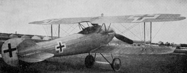
L.F.G. Roland D XIII
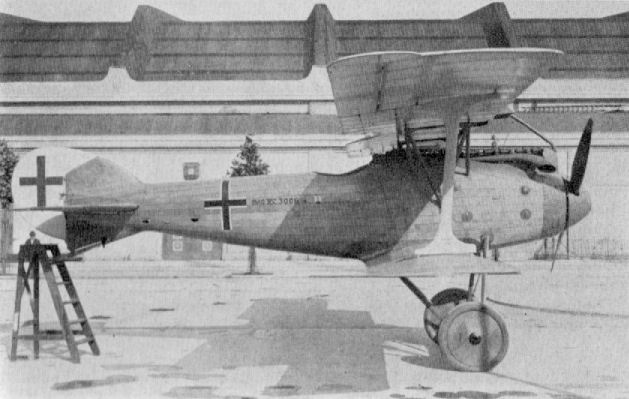
L.F.G. Roland D XV (second version)
L.F.G. Roland D XVI (first version)
The penultimate Roland lighter was this D XVI parasol monoplane, which was doubtless inspired by the success of the Fokker E V/D VIII parasol. In reverse fashion to the Fokker machine, the Roland had a fabric-covered wing and a plywood-sheet-covered fuselage, the sheet being applied with the grain running diagonally. Engine, 160 h.p. Siemens-Halske Sh III geared rotary. Armament, twin Spandau machine-guns.
L.F.G. Roland D XVI (second version)
In addition to having a different engine, the second D XVI prototype differed slightly in the shape of its vertical tail surfaces and in that the ply-sheet covering of the fuselage was no longer applied diagonally. Engine, 170 h.p. Goebel Goe III. Armament, twin Spandau machine-guns.
L.F.G. Roland D XVII
Last of the long line of Roland lighters was this D XVII parasol monoplane. It utilised the same type of fuselage and engine installation as the B.M.W.-powered D XV prototype. Engine, 185 h.p. B.M.W. III. Armament, twin Spandau machine-guns.
Last of the long line of Roland lighters was this D XVII parasol monoplane. It utilised the same type of fuselage and engine installation as the B.M.W.-powered D XV prototype. Engine, 185 h.p. B.M.W. III. Armament, twin Spandau machine-guns.
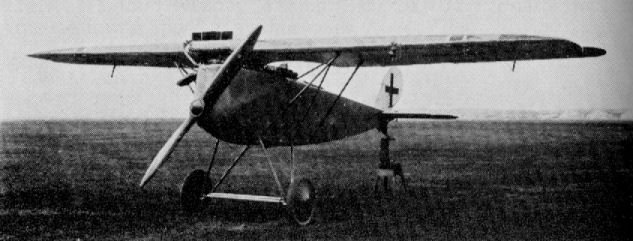
The last of a long line of LFG Roland fighters, their D XVII single seater was fitted with a 185hp BMW IIIa. Little reliable data survives on this machine, which is reported to have taken part in the second of the 1918 fighter trials. Note the position of the radiator, mounted to project forward of the wing centre section leading edge. This allowed the engine to be more smoothly cowled, but whether the radiator's position encroached upon the all-important fighter need for excellent forward pilot visibility is difficult to judge from this image.
L.F.G. Stralsund V 19
Developed at L.F.G. Stralsund during 1918, this sea monoplane was intended to be quickly and easily dismantled and assembled for operation from submarines. However, only a single experimental aircraft was built. Engine, 110 h.p. Oberursel U II.
Developed at L.F.G. Stralsund during 1918, this sea monoplane was intended to be quickly and easily dismantled and assembled for operation from submarines. However, only a single experimental aircraft was built. Engine, 110 h.p. Oberursel U II.
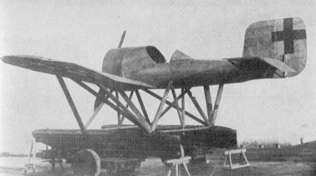
L.F.G. Stralsund V 19
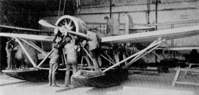
Linke-Hofmann R I
The design of the R I was taken up by the Breslau locomotive firm of Linke-Hofmann under the direction of Paul Stumpf, who became Chief Engineer when he joined them from the A.E.G. concern.
The fuselage design was developed as a result of model tests conducted in the Gottingen laboratory with encouraging results. Unfortunately the promise shown by the model was not realised in the actual aircraft when built. The four Mercedes D IVa engines were housed inside the fuselage and drove twin tractor airscrews through a system of shafts and gears.
Of vast proportions and ungainly appearance the first R I (8/15) made its maiden flight in the spring of 1917, but proved difficult to fly. In May the machine crashed from a low altitude when the wings collapsed and was completely written off, all the crew but one fortunately escaping. One of the flight trials' difficulties was the development of an adequate landing technique as the pilots sat about 20 ft. above the ground and a considerably degree of judgement was necessary.
Towards the end of 1917, R I (40/16) was completed and included necessary modifications highlighted by R 8/15's shortcomings. Both machines were of wooden construction, the multiple tail surfaces being a distinctive feature, and a further unique point was the steel-tyred landing wheels incorporating a multiplicity of steel springs. The first prototype had the fuselage covered with transparent Cellon material, and the ailerons had inset balances. Performance of R 40/16 was still far from satisfactory, although manoeuvrability was improved. It eventually crash landed, nosed over, and was not rebuilt. Engines, 4 x 260 h.p. Mercedes D IVa. Span. 33.2 m. (108 ft. 11 1/4 in.). Length, 15.6 m. (51 ft. 2 1/2 in.). Height, 6.7 m. (21 ft. 11 3/4 in.). Area, 265 sq.m. (2,851 sq.ft.). Weights: Empty, 8,000 kg. (17,640 lb.). Loaded, 11,200 kg. (24,696 lb.). Speed, 130 km.hr. (81.25 m.p.h.). Climb, 3,000 m. (9,840 ft.) in 2 hr. Duration, 5 hr. Armament, none fitted.
Linke-Hofmann R II
The experience gained with the R I prototypes led to the development of the R II which appeared in 1918. It was a considerably larger aeroplane and to an altogether different conception, based on an approximate three times enlargement of an orthodox single-engined biplane. In this machine the four engines were arranged in two pairs side-by-side, the front pair facing rearwards, and all were coupled to a central gearbox which drove the huge airscrew - some 22 ft. 8 in. in diameter - at 545 r.p.m.
Two prototypes were scheduled, R 55/17 and R 58/17, but in the event only the former ever flew and then only after the Armistice. Wooden construction with fabric covering was featured with most of the forward fuselage ply-covered. The undercarriage consisted of a neat steel-tube vee chassis - unusual in so large an aircraft and again steel-shod wheels with multiple steel springs were used.
It proved possible to fly the machine on two engines. The average fuel/payload arrangement gave a flight duration of approximately seven hours, but by careful adjustment of crew and fuel carried an extended duration of 30 hr. at 74 m.p.h. was estimated as being obtainable. Engines, 4 X 260 h.p. Mercedes D IVa. Span, 42.16 m. (138 ft. 4 in.). Length, 20.316 m. (66 ft. 7 7/8 in.). Height, 7.1 m. (23 ft. 3 5/8 in.). Area, 320 sq.m. (3,443 sq.ft.). Weights: Empty, 8,000 kg. (17.640 lb.). Loaded, 12,000 kg. (26,460 lb.). Speed, 130 km.hr. (81.25 m.p.h.). Climb, 1,000 m. (3,280 ft.) in 8 min., 2,000 m. (6,560 ft.) in 20 min. Duration, 7 hr. Armament, provision for two dorsal and one ventral machine-gun positions.
L.T.G. SD 1
Six of these single-seat seaplanes (Seejagdeinsitzer) with some variation of the tail surfaces were constructed by the Luft Torpedo Gesellschaft, Johannisthal, known initially as L.T.G. and whose official abbreviation was "Torp". The aircraft were ordered on 8th February 1917 and delivery completed by 8th March 1918. Marine numbers 1299-1301 and 1518-1520 were allocated. No. 1299 was used solely as an experimental machine and carried out load tests. The engine generally credited to this aircraft is 150 h.p. Benz Bz III, but from photographs it is obvious, from the hand of the airscrew, that some sort of geared motor was installed. Span, 10.0 m. (32 ft. 9 3/4 in.). Length, 9.0 m. (29 ft. 6 3/8 in.). Height, 3.55 m. (11 ft. 7 3/4 in.). Weights: Empty, 895 kg. (1,969 lb.). Loaded, 1,165 kg. (2,563 lb.).
Six of these single-seat seaplanes (Seejagdeinsitzer) with some variation of the tail surfaces were constructed by the Luft Torpedo Gesellschaft, Johannisthal, known initially as L.T.G. and whose official abbreviation was "Torp". The aircraft were ordered on 8th February 1917 and delivery completed by 8th March 1918. Marine numbers 1299-1301 and 1518-1520 were allocated. No. 1299 was used solely as an experimental machine and carried out load tests. The engine generally credited to this aircraft is 150 h.p. Benz Bz III, but from photographs it is obvious, from the hand of the airscrew, that some sort of geared motor was installed. Span, 10.0 m. (32 ft. 9 3/4 in.). Length, 9.0 m. (29 ft. 6 3/8 in.). Height, 3.55 m. (11 ft. 7 3/4 in.). Weights: Empty, 895 kg. (1,969 lb.). Loaded, 1,165 kg. (2,563 lb.).
Lubeck-Travemunde F 1
The Flugzeugwerft Lubeck-Travemunde G.m.b.H. was founded in May 1914 at Travemunde Privall, for the construction of seaplanes. First product was the F 1, a large four-bay two-seater with tapered wings, of which three examples were built, Nos. 282-284. Engine, 160 h.p. Mercedes D III.
Lubeck-Travemunde F 2
A total of eleven F 2s were supplied; comparatively large armed two-seaters with no less than four bays of struts in each wing panel. Radio transmitting equipment was carried, and the observer was armed with Parabellum machine-gun. Engine, 220 h.p. Mercedes D IV 8-cylinder, geared. Span, 19.0 m. (62 ft. 4 1/8 in.). Length, 11.32 m. (37 ft. 1 5/8 in.). Height, 3.575 m. (11 ft. 8 3/4 in.). Area, 86 sq.m. (929 sq.ft.). Weights: Empty, 1,540 kg. (3,388 lb.). Loaded, 2,204 kg. (4,849 lb.). Speed, 136 km.hr. (85 m.p.h.). Climb, 1,000 m. (3,280 ft.) in 10 min. Marine numbers allocated were 677 and 1147-1156. Machines varied slightly in dimensions and weights; data given is for No. 677.
Lubeck-Travemunde F 4
Thirty-four F 4 seaplanes were built in 1917-18 and were used on armed reconnaissance patrol duties. Radio was carried and in the illustration the aerial weight may be seen hanging underneath the fuselage mid-way between tail and wings. Marine numbers were 1971-1973, 2135 and 7001-7030. Engine, 200 h.p. Benz Bz IV. Span, 16.7 m. (54 ft. 9 1/2 in.). Length, 11.3 m. (37 ft. 0 7/8 in.). Height, 4.0 m. (13 ft. 1 1/2 in.). Area. 57.64 sq.m. (731 sq.ft.). Weights: Empty, 1,366 kg. (3,005 lb.). Loaded, 1,998 kg. (4,396 lb.). Speed, 138 km.hr. (86.25 m.p.h.). Climb, 1,000 m. (3,280 ft.) in 9.3 min. Armament, one Parabellum machine-gun in rear cockpit.
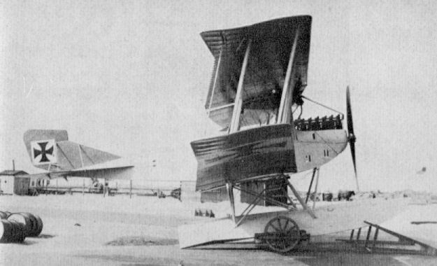
Lubeck-Travemunde F 1
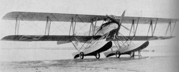
Lubeck-Travemunde F 2
Lubeck-Travemunde
This firm also built a single-seat seaplane. Marine No. 844, powered with a 150 h.p. Benz engine. No other details or photo available.
This firm also built a single-seat seaplane. Marine No. 844, powered with a 150 h.p. Benz engine. No other details or photo available.
L.V.G. B I, II and III
Luft-Verkehrs Gesellschaft m.b.H., located at the Berlin airfield of Johannisthal, became one of Germany's largest aircraft works. It utilized the old Parseval airship shed as a giant erecting shop until it was burned down in 1914. These premises were inherited from the pre-war days when the firm had operated Parseval-type airships on an air-traffic service which they advertised to good effect on the sides of the dirigibles. The airship service in fact gave rise to the firm's name, the literal translation of Luft Verkehrs G.m.b.H. being "Air Traffic Co. Ltd.".
The first aircraft to be manufactured were Farman types until Franz Schneider, a Swiss engineer previously with Nieuport, joined the firm in 1912 and started to produce original designs. His first successful tractor biplane design, the L.V.G. B I, flew before the war started (A and B class designations being used in 1913). It was later put into production, and was then also built under licence by the Otto firm in Munich for supply to the Bavarian Army. In June 1914 six B Is took part in the Ostmarkenflug: all were Mercedes-powered and took the first four places.
With the outbreak of war an excellent general-duties machine was immediately to hand. It was a conventional two-bay aircraft of the period. The fuselage was a simple wire-braced box-girder structure based on four spruce longerons and cross members. A 100 h.p. Mercedes D I engine was the usual power unit, although some machines were fitted with the 110 h.p. Benz. They were simply installed in the nose, with little attention to appearance; the crankcase was more or less enclosed in a curved-sheet metal decking, the cylinder block being starkly unshrouded. The exhaust collector was fitted to the port side of the Benz-engined version, the gases conducted forward and exhausted vertically downward, close by the propeller shaft. The rounded metal-decking panel on top of the fuselage extended to enclose both cockpits, in which the pilot sat aft. Radiators were mounted on the fuselage sides just above the leading edge of the lower wing attachment, and were of the type that could be added to or reduced, according to the temperature conditions. A gravity fuel tank was usually slung from the apex of the front pair of inverted-vee centre-section struts. Aft of the cockpit the fuselage was of perfectly plain rectangular section, fabric covered and tapered to a vertical knife-edge at the sternpost.
Tail surfaces were of welded 20 mm. steel-tube construction, and of flat plate section. The tailplane was a near equilateral triangle with considerable area; elevators were unbalanced and of ovoid profile. A plain triangular vertical fin of low aspect ratio was fitted, to which was hinged the unbalanced rudder.
Wings were an orthodox structure, two-bay and with a slight amount of overhang on the upper wings. Main spars were hollow box-girders of spruce, braced together with wooden compression members and steel cables. Both wings were of constant and equal chord, with slight rounding at the tips, which made for simplicity of manufacture. The ailerons were unbalanced and of rectangular shape, with an unusual "kink" at mid-span where the operating crank was located. This imparted to the outer half of the aileron an extreme washed-out section.
All struts were of wood, including those of the orthodox vee type undercarriage chassis, which included twin spreader bars and an axle sprung with elastic shock cord. The ash tailskid was mounted to a small inverted steel tube tripod at the extreme rear of the fuselage, and was also sprung with elastic shock cord.
<...>
L.V.G. B I
The L.V.G. B I saw service during the early months of the war on unarmed scouting duties and was also used for training purposes. As was usual in B-type machines, the pilot sat aft. The kink in the aileron, which imparted wash-out at the tip, remained a characteristic of the L.V.G. two-seaters up to the C V. The B I was soon replaced by the B II, which became the main production variant. Both machines were, however, very similar in style and construction. Engine, 110 h.p. Benz or 100 h.p. Mercedes. Span, 14.54 m. (47 ft. 8 1/2 in.). Length, 7.81 m. (25 ft. 7 1/2 in.). Height, 3.2 m. (10 ft. 6 in.). Area, 40 sq.m. (432 sq.ft.). Weights: Empty, 765 kg. (1,683 lb.). Loaded, 1,132 kg. (2,490 lb.). Speed, ca. 100 km.hr. (62.5 m.p.h.).
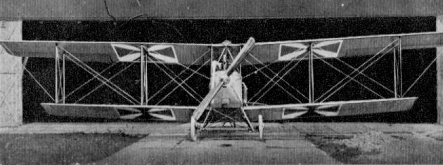
Otto B I (1914)
L.V.G. B I, II and III
<...>
The L.V.G. B II was very similar to the B I, but it had small improvements to obtain better operational efficiency. These did not alter the outward appearance very noticeably, apart from the reduction in wingspan. The main points which distinguished the B II from the B I were the siting of the gravity tank along the apex of the centre-section trestle (those built by Schutte-Lanz were offset slightly to port of the centre-section), the positioning of the rear cockpit farther aft and the introduction of a semicircular cut-out in the upper wing - all with a view to improving pilot visibility. The tailplane was braced to the underside of the fuselage with a single steel-tube strut instead of by two as formerly. Another change was the introduction of the 120 h.p. Mercedes D II, which was almost universally used on the B II, with consequent location of the downswept exhaust on the starboard side.
The L.V.G. B II became the main production model, and from the spring of 1915 it was used on scouting and reconnaissance sorties, but its main use was as a school machine. Production was carried on by both the Otto and Schutte-Lanz factories in addition to the parent firm.
The B II was undoubtedly a good flying machine, and was, in fact, assessed by the Inter-Allied Commission which investigated the German aircraft industry after the Armistice as "an excellent school machine". Naturally the trainer version was fitted with dual controls, and many of the later machines had frontal radiators mounted against the centre-section leading edge.
<...>
TECHNICAL DATA
Description: Unarmed two-seat scout, reconnaissance and training aircraft.
Manufacturers: Luft-Verkehrs Gesellschaft m.b.H. Johannisthal (Lvg.).
Sub-contractors: Otto-Werke G.m.b.H., Luftfahrzeugbau Schutte-Lanz.
Power Plant: One 100 h.p. Mercedes D I or 120 h.p. D II 6 cylinder in-line water-cooled engine.
Dimensions: Span, 12.12 m. (39 ft. 9 1/8 in.). Length, 8.30 m. (27 ft. 2 3/4 in.). Height 2.935 m. (9 ft. 8 in.). Area, 35.42 sq.m. (381.5 sq.ft.).
Weights: Empty, 726 kg. (1,597.2 lb.). Loaded, 1,074 kg. (2,362.8 lb.).
Performance: Maximum speed, 105 km.hr. (65.626 m.p.h.) at 1,000 m. Climb, 1,000 m. (3,280 ft.) in 12 min. Duration, 4 hr. on 173 litres fuel.
Armament: None.
N.B. Above data applies to Schutte-Lanz built B II fitted with 100 h.p. Mercedes D I motor and leading-edge radiator. Trainer version as in drawing.
<...>
The L.V.G. B II was very similar to the B I, but it had small improvements to obtain better operational efficiency. These did not alter the outward appearance very noticeably, apart from the reduction in wingspan. The main points which distinguished the B II from the B I were the siting of the gravity tank along the apex of the centre-section trestle (those built by Schutte-Lanz were offset slightly to port of the centre-section), the positioning of the rear cockpit farther aft and the introduction of a semicircular cut-out in the upper wing - all with a view to improving pilot visibility. The tailplane was braced to the underside of the fuselage with a single steel-tube strut instead of by two as formerly. Another change was the introduction of the 120 h.p. Mercedes D II, which was almost universally used on the B II, with consequent location of the downswept exhaust on the starboard side.
The L.V.G. B II became the main production model, and from the spring of 1915 it was used on scouting and reconnaissance sorties, but its main use was as a school machine. Production was carried on by both the Otto and Schutte-Lanz factories in addition to the parent firm.
The B II was undoubtedly a good flying machine, and was, in fact, assessed by the Inter-Allied Commission which investigated the German aircraft industry after the Armistice as "an excellent school machine". Naturally the trainer version was fitted with dual controls, and many of the later machines had frontal radiators mounted against the centre-section leading edge.
<...>
TECHNICAL DATA
Description: Unarmed two-seat scout, reconnaissance and training aircraft.
Manufacturers: Luft-Verkehrs Gesellschaft m.b.H. Johannisthal (Lvg.).
Sub-contractors: Otto-Werke G.m.b.H., Luftfahrzeugbau Schutte-Lanz.
Power Plant: One 100 h.p. Mercedes D I or 120 h.p. D II 6 cylinder in-line water-cooled engine.
Dimensions: Span, 12.12 m. (39 ft. 9 1/8 in.). Length, 8.30 m. (27 ft. 2 3/4 in.). Height 2.935 m. (9 ft. 8 in.). Area, 35.42 sq.m. (381.5 sq.ft.).
Weights: Empty, 726 kg. (1,597.2 lb.). Loaded, 1,074 kg. (2,362.8 lb.).
Performance: Maximum speed, 105 km.hr. (65.626 m.p.h.) at 1,000 m. Climb, 1,000 m. (3,280 ft.) in 12 min. Duration, 4 hr. on 173 litres fuel.
Armament: None.
N.B. Above data applies to Schutte-Lanz built B II fitted with 100 h.p. Mercedes D I motor and leading-edge radiator. Trainer version as in drawing.
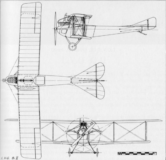
L.V.G. C I
The L.V.G. C I of 1915 was the first German operational two-seater aircraft in which the observer was armed with a machine-gun. Although a quantity of machines were supplied to the Fl. Abt., the main production variant was the C II which was almost identical in size and construction. Engine, 150 h.p. Benz Bz III. Span, 14.5 m. (47 ft. 7 in.). Length, 8.61 m. (28 ft. 3 in.). Height, 3.27 m. (10 ft. 8 3/4 in.). Area. 41.5 sq.m. (448 sq.ft.). Weights: Empty, 835 kg. (1,837 lb.). Loaded, 1,373 kg. (3,021 lb.). Speed, 100 km.hr. (62.5 m.p.h.). Armament, one Parabellum machine-gun.
The L.V.G. C I of 1915 was the first German operational two-seater aircraft in which the observer was armed with a machine-gun. Although a quantity of machines were supplied to the Fl. Abt., the main production variant was the C II which was almost identical in size and construction. Engine, 150 h.p. Benz Bz III. Span, 14.5 m. (47 ft. 7 in.). Length, 8.61 m. (28 ft. 3 in.). Height, 3.27 m. (10 ft. 8 3/4 in.). Area. 41.5 sq.m. (448 sq.ft.). Weights: Empty, 835 kg. (1,837 lb.). Loaded, 1,373 kg. (3,021 lb.). Speed, 100 km.hr. (62.5 m.p.h.). Armament, one Parabellum machine-gun.
L.V.G. C II
When the Allies introduced armed aircraft in 1915 the unarmed B type reconnaissance machines of the German Air Force soon began to suffer a prohibitive casualty rate and the introduction of defensive armament became imperative. This, in turn, made necessary the use of more powerful engines to carry the additional payload of gun(s) and ammunition, and gave rise to the C class designation, which was applied to armed two-seater aircraft of more than 150 h.p.
Franz Schneider of the L.V.G. firm had already experimentally equipped one of his monoplane designs with both a fixed forward-firing machine-gun and a manually operated machine-gun on a ring mounting for the observer, although this machine was unfortunately lost, due to wing failure, while being ferried to the Front in June 1915. Consequently when the demand arose for an armed reconnaissance machine Schneider was quickly able to produce an L.V.G. biplane with a ring-mounted machine-gun for defensive purposes. The machine itself was little more than a strengthened L.V.G. B I airframe fitted with a 150 h.p. Benz Bz III engine, and duly became the C I. It was the first German operational aircraft to be fitted with defensive armament. It passed into limited production until a more specifically designed aeroplane could take its place.
Such a machine, the C II, appeared towards the end of 1915 and came into widespread service with all types of unit, from the Kampfgeschwadern, where it was employed on light bombing duties, to Fl. Abt. units, where it was used upon tactical reconnaissance, photo reconnaissance and general "maid of all work" duties.
The C II bore a considerable degree of similarity to the B II, and the two types are easily confused. Apart from the installation of the 160 h.p. Mercedes D III engine in the nose with only the crankcase covered by the curved metal decking, the C II was almost identical with the less powerful B II. A large collector manifold, which exhausted through a "chimney" pipe over the upper wing, was mounted to starboard. The radiator was now of the frontal type, rectangular in elevation and recessed into a cut-out in the centre-section to be flush with the leading edge. Apart from the curved top decking, which extended aft to encompass the cockpit section, the rest of the aircraft was of plain rectangular cross-section, side and underneath being ply-covered back to the rear cockpit, aft of which the fuselage was fabric covered. The basic fuselage structure was still a cable-braced box-girder of spruce longerons and cross-members, although from the cockpit area forward the longerons were now spliced with ash.
The wings were practically identical to the B II, with the same type of "kinked" ailerons at the upper wingtips. All struts were now of streamlined steel tube including the inverted vee centre-section cabane. The gravity fuel tank, now torpedo shaped, was usually slung underneath the upper wing slightly to port of the centre-section, although sometimes it was attached to the upper surface.
The tail surfaces were much the same as on the B II, except for a degree of curvature on the tailplane leading edges to give some additional area. The undercarriage was an orthodox vee-type chassis of streamlined steel tube with coiled-steel-spring shock absorbers. The tailskid was now hinged on the line of the lower longerons and sprung internally with elastic cord.
Although initially armed with only a Parabellum gun for the observer, L.V.G. C IIs later had their armament strengthened by the addition of a fixed Spandau machine-gun firing forward, as was the case with most of the early C type two-seaters. Production quantities of the C II are not known, but the type was built under licence by both the Ago and Otto firms. According to the Inter-Allied Control Commission figures, some 250 aircraft of both C I and C II types were in service at the Front in the spring of 1916.
TECHNICAL DATA
Description: Two-seat reconnaissance and general duties.
Manufacturers: Luft-Verkehrs Gesellschaft m.b.H. Johannisthal (Lvg.).
Sub-contractors: Ago Flugzeug-Werke G.m.b.H., Otto-Werke G.m.b.H.
Power Plant: One 160 h.p. Mercedes D III 6 cylinder in-line water-cooled engine.
Dimensions: Span, 12.85 m. (42 ft. 2 in.). Length, 8.1 m. (26 ft. 7 in.). Height, 2.93 m. (9 ft. 7 1/4 in.). Area, 37.6 sq.m. (406.1 sq.ft.).
Weights: Empty, 845 kg. (1,859 lb.). Loaded, 1,405 kg. (3,091 lb.).
Performance: Maximum speed, 130 km.hr. (81.25 m.p.h.). Ceiling, 13,120 ft. Endurance, 4 hr.
Armament: One manually operated Parabellum machine-gun in rear cockpit at first; later forward-firing Spandau gun was additionally fitted.
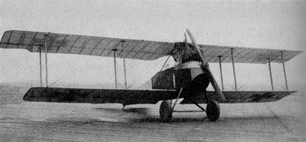
L.V.G. C I (C II ???)
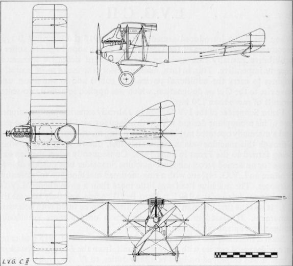
L.V.G. C III
This machine was virtually a standard L.V.G. C II with the observer transferred to the front cockpit, although in dimensions it did differ marginally. It remained only an experimental aircraft, and probably only the one machine was built. Engine, 160 h p . Mercedes D III. Span, 12.7 m. (41 ft. 8 in.). Length, 8.0 m. (26 ft. 3 in.). Height. 3.2 m. (10 ft. 6 in.). Area, 36 sq.m. (389 sq.ft.). Weights: Empty, 845 kg. (1,859 lb.). Loaded, 1,405 kg. (3,091 lb.). Armament, one Parabellum machine-gun in front cockpit.
This machine was virtually a standard L.V.G. C II with the observer transferred to the front cockpit, although in dimensions it did differ marginally. It remained only an experimental aircraft, and probably only the one machine was built. Engine, 160 h p . Mercedes D III. Span, 12.7 m. (41 ft. 8 in.). Length, 8.0 m. (26 ft. 3 in.). Height. 3.2 m. (10 ft. 6 in.). Area, 36 sq.m. (389 sq.ft.). Weights: Empty, 845 kg. (1,859 lb.). Loaded, 1,405 kg. (3,091 lb.). Armament, one Parabellum machine-gun in front cockpit.
L.V.G. 1915
Exact designation of this L.V.G. machine is not certain. It was a derivative of the C I, completed as a single-seat torpedo machine for the Navy, and test flown in June 1915 by Flugmeister Herz. The complicated and robust undercarriage, with the "oversize" tyres, may be seen. The "object" in the carrying cradle is thought to be a mock-up rather than an actual torpedo. Engine, 200 h.p. Benz Bz IV.
Exact designation of this L.V.G. machine is not certain. It was a derivative of the C I, completed as a single-seat torpedo machine for the Navy, and test flown in June 1915 by Flugmeister Herz. The complicated and robust undercarriage, with the "oversize" tyres, may be seen. The "object" in the carrying cradle is thought to be a mock-up rather than an actual torpedo. Engine, 200 h.p. Benz Bz IV.
L.V.G. E I
Designed by Franz Schneider, this L.V.G. monoplane of 1915 was the first German aircraft to be fitted with both a fixed machine-gun for the pilot and manually operated machine-gun on ring mounting for the observer. There was undoubted promise in the design, but unfortunately the prototype was destroyed when being ferried to the Front for operational assessment by Lt. Wentsch. It was later found that the lower wing struts had not been screwed in sufficiently, and as a result the wings collapsed. No further examples were built. Engine, 120 h.p. Mercedes D II. Military Serial No.: E 600/15.
Designed by Franz Schneider, this L.V.G. monoplane of 1915 was the first German aircraft to be fitted with both a fixed machine-gun for the pilot and manually operated machine-gun on ring mounting for the observer. There was undoubted promise in the design, but unfortunately the prototype was destroyed when being ferried to the Front for operational assessment by Lt. Wentsch. It was later found that the lower wing struts had not been screwed in sufficiently, and as a result the wings collapsed. No further examples were built. Engine, 120 h.p. Mercedes D II. Military Serial No.: E 600/15.
L.V.G. G I
Although designated in the G series, this 1915 aircraft was more in the nature of a "Battleplane" (in common with the A.E.G. G I) than a bombing aircraft. As far as is known only a single machine was built. Engines, two 150 h.p. Benz Bz III driving handed airscrews.
Although designated in the G series, this 1915 aircraft was more in the nature of a "Battleplane" (in common with the A.E.G. G I) than a bombing aircraft. As far as is known only a single machine was built. Engines, two 150 h.p. Benz Bz III driving handed airscrews.
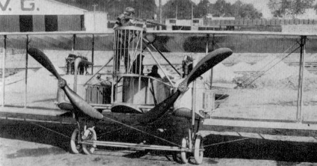
L.V.G. G I
L.V.G. C IV
This 1916 aircraft was a slightly enlarged edition of the C II designed round the straight-eight 220 h.p. Mercedes D IV engine. The reduction gearing enabled the engine to be almost completely buried, and a slow-revolving propeller of massive proportions was fitted. The introduction of a balanced rudder for the first time on an L.V.G. two-seater may be noted. An L.V.G. C IV made the first daylight aeroplane raid on London 28th November 1916. Engine, 220 h.p. Mercedes D IV. Span, 13.6 m. (44 ft. 7 1/2 in.). Length, 8.5 m. (27 ft. 10 3/4 in.). Height, 3.1 m. (10 ft. 2 1/8 in.). Area, 38.2 sq.m. (413 sq.ft.). Weights: Empty, 1,050 kg. (2,310 lb.). Loaded, 1,600 kg. (3,520 lb.). Armament, one Parabellum machine-gun.
This 1916 aircraft was a slightly enlarged edition of the C II designed round the straight-eight 220 h.p. Mercedes D IV engine. The reduction gearing enabled the engine to be almost completely buried, and a slow-revolving propeller of massive proportions was fitted. The introduction of a balanced rudder for the first time on an L.V.G. two-seater may be noted. An L.V.G. C IV made the first daylight aeroplane raid on London 28th November 1916. Engine, 220 h.p. Mercedes D IV. Span, 13.6 m. (44 ft. 7 1/2 in.). Length, 8.5 m. (27 ft. 10 3/4 in.). Height, 3.1 m. (10 ft. 2 1/8 in.). Area, 38.2 sq.m. (413 sq.ft.). Weights: Empty, 1,050 kg. (2,310 lb.). Loaded, 1,600 kg. (3,520 lb.). Armament, one Parabellum machine-gun.
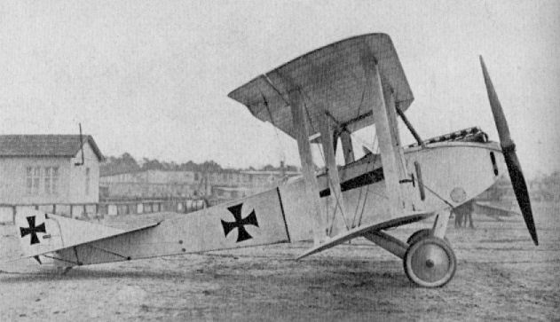
L.V.G. C IV
L.V.G. D 10
Experimental single-seat fighter with wrapped plywood strip fuselage of deep gap-filling Walfisch type. The unique under-fin extending to the axle is one of the many features of this unusual-looking aeroplane which was built during 1916. Engine, 120 h.p. Mercedes D II.
Experimental single-seat fighter with wrapped plywood strip fuselage of deep gap-filling Walfisch type. The unique under-fin extending to the axle is one of the many features of this unusual-looking aeroplane which was built during 1916. Engine, 120 h.p. Mercedes D II.
L.V.G. D II (D 12)
Built at the end of 1916, this single-seat fighter with monocoque-type fuselage and vee interplane strut arrangement was the second in a series of experimental D types. There was no L.V.G. D I as such, the designation being allocated to the Albatros D II, which was licence-built by L.V.G. The L.V.G. D II was fitted with 160 h.p. Mercedes D III. No other data.
Built at the end of 1916, this single-seat fighter with monocoque-type fuselage and vee interplane strut arrangement was the second in a series of experimental D types. There was no L.V.G. D I as such, the designation being allocated to the Albatros D II, which was licence-built by L.V.G. The L.V.G. D II was fitted with 160 h.p. Mercedes D III. No other data.
L.V.G. B I, II and III
<...>
As late as 1917 it was still thought worthwhile to revise the basic design for continued use as a trainer type. This variant was the B III, and practically all that was done was to revise the tail surfaces to more modern and efficient lines and to strengthen the rear fuselage by covering it with ply sheet better to withstand the rough treatment from inexperienced students, this final type was built by both the Schutte-Lanz and Euler firms.
L.V.G. B III (Schul)
Developed in 1917, the L.V.G. B III was used specifically for training. The tail surfaces had been modernised in comparison with the earlier B types, and the fuselage was ply-covered as far aft as the cockpit, as were the rear section and vertical fin for additional strength. Also licence-built by the Schutte-Lanz company, one of whose machines is illustrated. Engine, 120 h.p. Mercedes D II. Span, 12.51 m. (42 ft. 0 1/4 in.). Length, 7.89 m. (25 ft. 10 7/8 in.). Height, 2.89 m. (9 ft. 5 3/4 in.). Area, 32.15 sq.m. (357 sq.ft.). Weights: Empty, 738 kg. (1,785 lb.). Loaded, 1,042 kg. (2,292 lb.). Speed, 120 km.hr. (75 m.p.h.). Climb, 3,000 m. (9,840 ft.) in 28 min. Duration, 2.5 hr.
Euler B III
Built during 1918 for training duties, the B III was a licence-built L.V.G. B III, but differed from the parent machine by the introduction of a considerable degree of stagger, although an unstaggered version first existed. Engine, 120 h.p. Mercedes D II. Span, 12.5 m. (41 ft. 0 1/4 in.). Length, 7.89 m. (25 ft. 10 5/8 in.). Speed, 120 km.hr. (75 m.p.h.).
L.V.G. C V
One of the most successful German two-seaters used during the latter part of the war on reconnaissance and artillery observation duties was the L.V.G. C V, introduced into the Fl. Abt. units during 1917. This machine, although not as powerful as its high-flying Rumpler contemporaries, adequately filled the need for a stable and sturdy "all rounder" for light bombing, artillery observation and medium-range photo-reconnaissance duties. For its power it was a relatively large aeroplane, with a wingspan of nearly 45 ft., being one of the biggest of the German two-seaters.
In spite of its size, the L.V.G. C V was neat and well proportioned and represented a vast improvement upon its C II forebear, both in appearance and construction. In the C V the braced box-girder type fuselage of the earlier machines was discontinued, and in its place was a framework of longerons and bulkheads covered with a thin layer of three-ply, with no internal wire bracing. The 220 h.p. Benz Bz IV engine was neatly installed and mounted on hefty timber bearers of rectangular section. The whole of the cylinder block was enclosed by metal panels, likewise the station between the first two bulkheads and the upper panels of the nose. A large streamlined spinner enclosed the propeller hub and made for a very clean nose-entry, although this was to some extent negatived by the large frontal radiator mounted against the leading edge of the upper centre-section. A "chimney" type manifold exhausted over the top wing. The remainder of the ply-covered fuselage was slab-sided, with rounded top decking, and tapered to a vertical knife-edge aft, where the built-in vertical fins (upper and lower) were also ply-skinned. The oval tailplane was of wooden framing with fabric covering. Reminiscent of the Albatros types, the one-piece balanced elevator and balanced rudder were of welded steel tube and fabric covered.
The fabric-covered, unstaggered two-bay wings were orthodox in construction, but differed from the "run of the mill" in profile. The upper wing was in two panels, of parallel chord, with the tips rounded from the leading edge in a wide radiused curve. The lower wing was of slightly less span and chord, had completely rounded tips and a slight positive curve to most of the trailing edge, giving a dragonfly-wing outline. All wing panels were based on two box-spars with four cable-braced steel-tube compression members, "C" section leading edge and the usual wire trailing edge. Ribs were of ply, unlightened and with softwood capping strips reinforced with glued fabric. False ribs (a mere wooden slat) were interspaced on the upper wing only. Dihedral was differential, with 1° on the upper and 2° on the lower panels. Ailerons, on the upper wing only, were of parallel chord with large overhung balance portions of semicircular shape and were of welded steel-tube framing.
Centre-section struts were of streamlined steel tube welded to form a trestle to which the upper wing panels were attached. These converging centre-section struts, together with the large frontal radiator and the cowling panels enclosing the cylinders, combined to produce poor forward visibility from the front cockpit, a major defect of the C V. The interplane struts were of hollowed wood throughout, a departure from the usual German practice of the period. The vee struts of the undercarriage chassis were again of wood, fabric wrapped for added strength. The axle was encased in a three-ply fairing, but not the spreader bar, which connected the two vees in front of the axle. On aircraft fitted with radio a small propeller-driven generator was mounted at the top of the front undercarriage strut. Shock absorbers were of coiled-steel springs wrapping the axle to the apices of the vees. A sturdy ash tailskid was hinged to the apex of the under-fin and the upper end bound in with elastic shock cord.
By the autumn of 1917 the L.V.G. C Vs were coming into widespread use alongside the contemporary D.F.W. two-seater. On artillery shoots they often fell victims to Allied scouts when their own protection flights were not immediately to hand. However, they were often able to give a good account of themselves, as witness an account by McCudden, who, on 23rd December 1917, was involved in a fight at about 17,000 ft. with two L.V.G. C Vs:
"I at once gave chase and they turned east. I fought them for about five minutes but could not gain a decision for they both co-operated well and soon I left them for I hadn't much more petrol. While I was fighting these two they were both using their front guns as well as the rear, and so I had a fairly warm time."
It is perhaps of interest to point out that earlier McCudden had shot down an L.V.G. C V and had fitted the spinner from it to his S.E.5, and thereby increased the speed by some three miles an hour.
Some L.V.G. C Vs were used by Infanterie Flieger units, and these aircraft had the main fuel tank, which was underneath the pilot's seat, protected by a sheet of armoured steel.
TECHNICAL DATA
Description: Two-seat reconnaissance and artillery observation.
Manufacturers: Luft-Vcrkehrs Gesellschaft m.b.H. Johannisthal (Lvg.).
Sub-contractors: Deutsche Flugzeug-Werke G.m.b.H.
Power Plant: One 200 h.p. Benz Bz IV 6 cylinder in-line water-cooled engine developing maximum 230 h.p.
Dimensions: Span, 13.62 m. (44 ft. 8 1/2 in.). Length, 8.07 m. (26 ft. 5 3/4 in.). Height, 3.2 m. (10 ft. 6 in.). Area, 42.7 sq.m. (464.16 sq.ft.).
Weights: Empty, 1,013 kg. (2,228 lb.). Loaded, 1,533 kg. (5,372.6 lb.). Empty, 2,188 lb. Loaded, 3,141 lb. (Captured aircraft.)
Performance: Maximum speed, 164 km.hr. (103 m.p.h.) at 2,000 m. (6,560 ft.), 150 km.hr. (93.75 m.p.h.) at 4,000 m. (13,120 ft.). Climb, 4,000 m. (13,120 ft.) in 35 min. Duration, ca. 3 1/2 hr. on 249 litres fuel.
Armament: One fixed Spandau machine-gun forward and one manually operated Parabellum machine-gun in the rear cockpit.
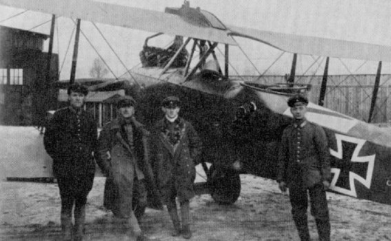
One of the work-horses of the artillery observation flights, the L.V.G. C V, with an interesting insignia displayed on the fuselage.
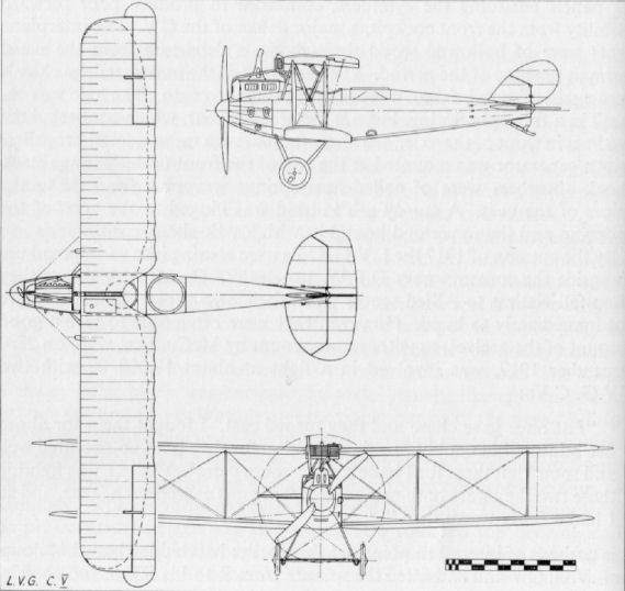
L.V.G. D III
In this 1917 experimental single-seat fighter an attempt at semi-rigid bracing was made in that the landing wires were replaced by struts, although flying wires remained. The gap-filling fuselage of the two previous types was abandoned, although the plywood covering and monocoque-type construction was retained. Wings were of conventional type, with fabric covering, but of considerable span for a single-seater. The lower tips were rounded, the upper tips slightly raked and with horn-balanced ailerons. Engine, 190h.p. N.A.G. III. Span, 10.0 m. (32 ft. 9 3/4 in.). Length, 7.53 m. (24 ft. 8 1/2 in.). Height, 2.92 m. (9 ft. 7 in.). Area, 26.2 sq.m. (283 sq.ft.) Weights: Empty, 816 kg. (1,795 lb.). Loaded, 1,071 kg. (2,356 lb.). Speed, 175 km.hr. (109.375 m.p.h.). Climb, 5,000 m. (16,400 ft.) in 25 min. Duration, 2 hr. Armament, twin Spandau machine-guns. Official type test May-June 1917.
In this 1917 experimental single-seat fighter an attempt at semi-rigid bracing was made in that the landing wires were replaced by struts, although flying wires remained. The gap-filling fuselage of the two previous types was abandoned, although the plywood covering and monocoque-type construction was retained. Wings were of conventional type, with fabric covering, but of considerable span for a single-seater. The lower tips were rounded, the upper tips slightly raked and with horn-balanced ailerons. Engine, 190h.p. N.A.G. III. Span, 10.0 m. (32 ft. 9 3/4 in.). Length, 7.53 m. (24 ft. 8 1/2 in.). Height, 2.92 m. (9 ft. 7 in.). Area, 26.2 sq.m. (283 sq.ft.) Weights: Empty, 816 kg. (1,795 lb.). Loaded, 1,071 kg. (2,356 lb.). Speed, 175 km.hr. (109.375 m.p.h.). Climb, 5,000 m. (16,400 ft.) in 25 min. Duration, 2 hr. Armament, twin Spandau machine-guns. Official type test May-June 1917.
L.V.G. D IV
Continuing the streamlined, ply-covered fuselage trend, the L.V.G. D IV featured a wing cellule similar to that of the earlier D II, with single-spar lower wing and vee interplane struts. The nose, of blunter proportions but still neatly spinnered, housed the vee-eight type, direct-drive, 195 h.p. Benz Bz IIIb engine. The machine participated at the second D types Competition at Adlershof in June 1918. Span, 8.5 m. (27 ft. 10 3/4 in.). Length, 6.28 m. (20 ft. 7 1/4 in.). Height, 2.7 m. (8 ft. 10 1/4 in.). Area, 18.06 sq.m. (195 sq.ft.). Weights: Empty, 680 kg. (1,496 lb.). Loaded, 935 kg. (2,057 lb.). Climb, 5,000 m. (16,400 ft.) in 28 min. at loaded weight of 911 kg. (2,004 lb.).
Continuing the streamlined, ply-covered fuselage trend, the L.V.G. D IV featured a wing cellule similar to that of the earlier D II, with single-spar lower wing and vee interplane struts. The nose, of blunter proportions but still neatly spinnered, housed the vee-eight type, direct-drive, 195 h.p. Benz Bz IIIb engine. The machine participated at the second D types Competition at Adlershof in June 1918. Span, 8.5 m. (27 ft. 10 3/4 in.). Length, 6.28 m. (20 ft. 7 1/4 in.). Height, 2.7 m. (8 ft. 10 1/4 in.). Area, 18.06 sq.m. (195 sq.ft.). Weights: Empty, 680 kg. (1,496 lb.). Loaded, 935 kg. (2,057 lb.). Climb, 5,000 m. (16,400 ft.) in 28 min. at loaded weight of 911 kg. (2,004 lb.).
L.V.G. C VI
Following the L.V.G. C V into service in 1918 came the C VI, of which some 1,000 odd examples were built up to the end of the war. In general, it did not differ greatly from its predecessor, but was lighter and slightly more compact, with the accent on utility and serviceability rather than nicety of line.
The same 200 h.p. Benz Bz IV engine was installed, although without a spinner, and the extreme forward end of the fuselage simply enclosed in bulbous metal panels. The cylinder block was no longer cowled in, and the radiator was of the flush type installed in the revised centre-section panel, which featured a large angular cut-out in the trailing edge. All these factors, coupled with the staggering of the upper wing some 10 in. farther forward, combined to give a much superior view from the front cockpit than was the case with the C V. Although slightly shorter, the fuselage was of the same basic construction and completely plywood covered, except for the metal panels of the nose section. Tail surfaces were also very similar to those of the earlier C V, retaining the wooden-framed fin surfaces, although the profile of the horizontal surfaces was much rounder, resulting in reduced span and increased chord.
The wings again followed the C V style of construction, but with the substitution of wooden compression members for steel tube. The upper panels were slightly raked at the tips, with a large radius curve on the leading edge. Ailerons were of parallel chord and no longer balanced, falling entirely within the tip profile. With the exception of the steel tube crank at mid-span, they were entirely of wooden framing, which seems to indicate the need for economy in the use of steel at this juncture. The lower wing panels presented a different outline from those of the C V, the trailing edge now being straight and parallel to the leading edge and the tips rounded in a near semicircular curve. At the roots were quadrant cut-outs to improve downward visibility.
Undercarriages of both C V and C VI were identical in design and material, including the tailskid; however, in the C VI the under-fin was simplified and strengthened.
Some L.V.G. C VIs were fitted with "ear"-type radiators on the sides of the fuselage, but it has not been possible to establish whether this cooling system was ever standardised.
The figures on captured aircraft showed the loaded weight of the C VI to be 105 lb. (almost 1 cwt.) less than the C V, which factor undoubtedly contributed to its improved performance.
An instance of a typical artillery observation sortie is translated from a report by Frhr von Peckmann, himself an L.V.G. observer.
"At 6 a.m. on a bright June (1918) morning we took off to register targets for a heavy field battery and a 15 cm. gun in the vicinity of Albert.
"An ammunition dump at Becourt-Becordel was earmarked as the primary target. A shoot was also to be carried out on a sugar factory at Ribemont, to subdue a hostile battery that was shelling our line of communication. A message to our battery and the guns were seen to flash. Some 40 seconds later the shells were observed bursting about 200 yards short whereupon the enemy battery ceased firing in an endeavour to conceal its position. We were not deceived, however, and after giving correction the next salvo placed two shells upon the sugar factory and two close by. After half an hour of bombardment the whole factory went up in flames including the ammunition dump of the enemy battery. During this period five enemy fighters appeared but did not attack due to the proximity of a Staffel of triplanes as top cover overhead.
"Our next target was a battery on the outskirts of Hesle on which we registered for nearly two hours, after which period ground signals were laid out for us to proceed to our final target. As we had been airborne some two hours we were anxious to get the job done before our fuel became exhausted. This third target was the most important and difficult; an ammunition dump to the east of Warloy. As our triplane escort had now to depart and was being relieved by a patrol of Albatroses, some Sopwiths attempted to surprise us by diving out of the sun. Before we could get to work we were twice driven well back behind our own lines. Our Albatroses then attacked the enemy scouts and one was soon sent down in flames, whereupon the others retired and work was resumed.
"The first shell dropped in Warloy itself, some 550 yards short of the target but, by good fortune, disorganised a motor transport column which was given a few more shells for good measure. While studying the results through binoculars, supposedly secure in the knowledge of the protective Albatroses overhead, I was rudely awakened by the rattle of machine-gun fire to find two Sopwiths blazing away less than 100 yards distant. The radiator was riddled and with the boiling water streaming past our faces, my pilot put the L.V.G. into a steep spiral. It was only by his skilled manoeuvring that we were able to avoid further bullets from the persistent Englishmen; in fact so steep did our descent become I thought our L.V.G. was really out of control and the pilot badly wounded. However, the engine lasted as far as Montauban before seizing completely. There was no chance to select a landing place for even the shell holes overlapped, but with great skill the machine was put down in a clear patch no more than 15 yards long. Two days later, with a new engine fitted, we were once again about our business."
One surviving example of an L.V.G. C VI is in the hands of the Shuttleworth Collection's air museum at Old Warden, Beds. Shot down 2nd August 1918 by two S.E. 5s of No. 74 Squadron, it later flew at the R.A.F. Hendon Display in 1937. It has recently been refurbished after long storage.
TECHNICAL DATA
Description: Two-seat reconnaissance and artillery observation.
Manufacturer: Luft-Verkehrs Gesellschaft m.b.H. Johannisthal, Berlin (Lvg.).
Power Plant: One 200 h.p. Benz Bz IV 6 cylinder in-line water-cooled engine, developing maximum 230 h.p.
Dimensions: Span, 130 m. (42 ft. 7 3/4 in.). Length, 7.45 m. (24 ft. 5 1/4 in.). Height, 2.8 m. (9 ft. 2 1/4 in.). Area, 34.6 sq.m. (375.68 sq.ft.).
Weights: Empty, 930 kg. (2,046 lb.). Loaded, 1,309 kg. (3,058 lb.). Empty, 2,090 lb. Loaded, 3,036 lb. (Captured aircraft.)
Performance: Maximum speed, 170 km.hr. (106.25 m.p.h.). Climb, 1,000 m. (3,280 ft.) in 4 min., 2,000 m. (6,560 ft.) in 8 min., 3,000 m. (9,840 ft.) in 15 min., 6,000 m. (19,680 ft.) in 40 min. Ceiling, 21,350 ft. Duration, 3 1/2 hr.
Armament: One fixed Spandau machine-gun forward and one manually operated Parabellum machine-gun in the rear cockpit. Light bomb-load, up to 250 lb.
L.V.G. C VIII
Final two-seater to emerge from the L.V.G. factory during the First World War was the C VIII of 1918. Although not vastly different from the C VI, there were larger and shallower cut-outs in the wings and ailerons with a link strut fitted at all four wingtips. The high-compression 200 h.p. Benz IV u. engine developed some 240 h.p. at rated altitude and was fitted with a large car-type radiator on the extreme nose. Only one aircraft was completed. Engine, 200 h.p. Benz Bz IV u. Span, 13.0 m. (42 ft. 7 7/8 in.). Length, 7.0 m. (22 ft. 11 5/8 in.). Height, 2.8 m. (9 ft. 2 1/4 in.). Area, 35.7 sq.m. (386 sq.ft.). Weights: Empty, 975 kg. (2,145 lb.). Loaded, 1,380 kg. (3,036 lb.). Speed, 165km.hr.(103.125 m.p.h.). Duration,4hr. Armament, one Spandau and one Parabellum machine-guns.
Final two-seater to emerge from the L.V.G. factory during the First World War was the C VIII of 1918. Although not vastly different from the C VI, there were larger and shallower cut-outs in the wings and ailerons with a link strut fitted at all four wingtips. The high-compression 200 h.p. Benz IV u. engine developed some 240 h.p. at rated altitude and was fitted with a large car-type radiator on the extreme nose. Only one aircraft was completed. Engine, 200 h.p. Benz Bz IV u. Span, 13.0 m. (42 ft. 7 7/8 in.). Length, 7.0 m. (22 ft. 11 5/8 in.). Height, 2.8 m. (9 ft. 2 1/4 in.). Area, 35.7 sq.m. (386 sq.ft.). Weights: Empty, 975 kg. (2,145 lb.). Loaded, 1,380 kg. (3,036 lb.). Speed, 165km.hr.(103.125 m.p.h.). Duration,4hr. Armament, one Spandau and one Parabellum machine-guns.
L.V.G. D V
Another 195 h.p. Benz-powered prototype, the D V of 1918 reverted to a slab-sided ply-covered fuselage. Most singular feature was the juxtapositioning of the wing surfaces, the lower one being of much broader chord, and the main lifting surface. The narrow-chord upper-wing panels pivoted differentially outboard of the centre-section, the entire surface of both wings acting as "ailerons" to provide lateral manoeuvre.
L.V.G. D VI
Final fighter to emerge from the L.V.G. stable was this aggressive-looking D VI. It had many unique features: chin-type radiator air intake, swept lower wing, metal strap bracing, "I"-type interplane struts and a lifting surface on the axle as featured on Fokker aircraft. The almond-shaped rudder was pivoted on a tubular spar, and would appear to have been a highly vulnerable assembly. Engine, 195 h.p. Benz Bz IIIb.
L.V.G. G III
This huge triplane bomber appeared just before the war ended; it was constructed by L.V.G. to Schutte-Lanz design (Schul G V). It was of wooden construction with plywood-covered, streamlined fuselage and fabric-covered wings. Engines, 2 X 245 h.p. Maybach Mb IV. Span, 24.6 m. (80 ft. 4 3/4 in.). Length, 10.25 m. (33 ft. 7 1/2 in.). Height. 3.9 m. (12 ft. 9 5/8 in.). Area, 115 sq.m. (1,242 sq.ft.). Weights: Empty, 2,960 kg. (5,920 lb.). Loaded, 4,100 kg. (9,020 lb.). Speed, 130 km.hr. (81.25 m.p.h.). Climb, 3,000 m. (9,840 ft.) in 20 min. Duration, 5 1/2 hr. Armament, Parabellum machine-guns in nose and dorsal positions.
This huge triplane bomber appeared just before the war ended; it was constructed by L.V.G. to Schutte-Lanz design (Schul G V). It was of wooden construction with plywood-covered, streamlined fuselage and fabric-covered wings. Engines, 2 X 245 h.p. Maybach Mb IV. Span, 24.6 m. (80 ft. 4 3/4 in.). Length, 10.25 m. (33 ft. 7 1/2 in.). Height. 3.9 m. (12 ft. 9 5/8 in.). Area, 115 sq.m. (1,242 sq.ft.). Weights: Empty, 2,960 kg. (5,920 lb.). Loaded, 4,100 kg. (9,020 lb.). Speed, 130 km.hr. (81.25 m.p.h.). Climb, 3,000 m. (9,840 ft.) in 20 min. Duration, 5 1/2 hr. Armament, Parabellum machine-guns in nose and dorsal positions.
Markische D I
Designed by Hillmann, who is seen standing against the aircraft, this single-seat fighter was an original design built by Markische Flugzeug-Werke. They were mainly sub-contractors and built 700 Rumpler C Is under licence. Engine, 195 h.p. Benz Bz IIIb.
Designed by Hillmann, who is seen standing against the aircraft, this single-seat fighter was an original design built by Markische Flugzeug-Werke. They were mainly sub-contractors and built 700 Rumpler C Is under licence. Engine, 195 h.p. Benz Bz IIIb.
Naglo Quadruplane
Built by Naglo Bootswerft of Spandau, Berlin, in 1918, this experimental single-seater was based on an Albatros D V type fuselage. The manner in which the bottom wing was attached to an extruded keel and braced with splayed struts, completely independent of the three main lifting surfaces, conveys the impression it was added as an afterthought. The machine was listed under serial D 1161/18 as Naglo D II for the second D types Competition at Adlershof in the summer of 1918, but no record of performance figures is available. Design was by Ing. Gradig, who was still with Albatros and, as a result, he was dismissed by that firm. The official type test was undertaken on 24th May 1918, but the machine was rejected at the request of Schubert of Albatros. Engine, 160 h.p. Mercedes D III. Span, 9.0 m. (29 ft. 6 3/8 in.). Area, 22.4 sq.m. (242 sq.ft.). Weights: Empty, 724 kg. (1,593 lb.). Loaded, 914 kg. (2,011 lb.).
Built by Naglo Bootswerft of Spandau, Berlin, in 1918, this experimental single-seater was based on an Albatros D V type fuselage. The manner in which the bottom wing was attached to an extruded keel and braced with splayed struts, completely independent of the three main lifting surfaces, conveys the impression it was added as an afterthought. The machine was listed under serial D 1161/18 as Naglo D II for the second D types Competition at Adlershof in the summer of 1918, but no record of performance figures is available. Design was by Ing. Gradig, who was still with Albatros and, as a result, he was dismissed by that firm. The official type test was undertaken on 24th May 1918, but the machine was rejected at the request of Schubert of Albatros. Engine, 160 h.p. Mercedes D III. Span, 9.0 m. (29 ft. 6 3/8 in.). Area, 22.4 sq.m. (242 sq.ft.). Weights: Empty, 724 kg. (1,593 lb.). Loaded, 914 kg. (2,011 lb.).
N.F.W. B I
Built in 1915 by National Flugzeug-Werke G.m.b.H. Johannisthal, the B I was a conventional trainer type machine. Although not confirmed, the engine appears to be a 120 h.p. Argus As II.
Built in 1915 by National Flugzeug-Werke G.m.b.H. Johannisthal, the B I was a conventional trainer type machine. Although not confirmed, the engine appears to be a 120 h.p. Argus As II.
N.F.W. E I
This small experimental monoplane was built in the spring of 1916 to the plans of Dipl. Ing. Hergt. The twin spars of the ply-covered cantilever wings passed right through the fuselage, the pilot sitting between them. The type was not proceeded with, as the firm found their repair and training school work to be more profitable than aircraft manufacture. Engine, 80 h.p. Oberursel U O. Span, 10.0 m. (32 ft. 9 3/4 in.). Length, 6.5 m. (21 ft. 3 3/4 in.). Area, 15.72 sq.m. (170 sq.ft.). Weights: Empty, 428 kg. (641 lb.). Loaded, 620 kg. (1,364 lb.). Speed, 156 km.hr. (97.5 m.p.h.). Climb, 1,300 m. (4,264 ft.) in 6 min.
N.F.W. Experimental Monoplane
This machine was virtually the E I with revised tail surfaces.
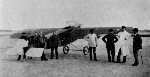
N.F.W. E I
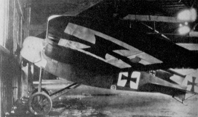
N.F.W. Experimental Monoplane
N.F.W. E II
Built during 1917, again to the designs of Hergt, this all wooden monoplane was identical in construction to the E. I, very similar in appearance and fitted with the 160 h.p. Mercedes engine. Again it remained no more than a prototype. Engine, 160 h.p. Mercedes D III. Span. 120 m. (39 ft. 4 1/2 in.). Area, 170 sq, m. (184 sq.ft.). Weights: Empty, 558 kg (1,228 lb.). Loaded, 768 kg. (1,690 lb.). Speed. 180 km.hr. (112.5 m.p.h.) Climb, 2,900 m. (9,512 ft.) in 6.3 min. No photograph available.
Built during 1917, again to the designs of Hergt, this all wooden monoplane was identical in construction to the E. I, very similar in appearance and fitted with the 160 h.p. Mercedes engine. Again it remained no more than a prototype. Engine, 160 h.p. Mercedes D III. Span. 120 m. (39 ft. 4 1/2 in.). Area, 170 sq, m. (184 sq.ft.). Weights: Empty, 558 kg (1,228 lb.). Loaded, 768 kg. (1,690 lb.). Speed. 180 km.hr. (112.5 m.p.h.) Climb, 2,900 m. (9,512 ft.) in 6.3 min. No photograph available.
Oertz V1 Eindecker
The V1 with a 7-cylinder Gnome of 70 hp was first flown on September 4, 1911 by Ernst Dax. Unfortunately it crashed shortly after on October 21, 1911.
Oertz V2
The Oertz V2 was flown by Wijnmalen on the Luneberger Heide in early February 1912 at the flying field of the Oertz company at Schneverdingen.
Oertz V4
The Oertz V4 (100 hp 14-cylinder Gnome rotary) first flew on March 31, 1912, flown by Henri Wijnmalen. Owing to speed of 172 km/hour that the machine attained on a flight from Bremen to Hamburg (with tailwind !). Wijnmalen got the idea to make a racing variant and to participate in the Gordon Bennett Race in September 1912 in Chicago. Unfortunately there was not enough money for the journey to the USA. So the machine never participated.
The machine was offered to the Prussian Fliegertruppe, but was not bought with the reason that 'the machine was too fast for normal flyers'.
In Chicago Jules Vedrines won the race with a speed of 174 km/hour.
There is a note that one Oertz Eindecker (unknown) type was bought by Krupp for a price of 25,000 DM.
Oertz V5
This machine is designated Max Oertz V5. Machine was powered by a 14-cylinder rotary engine (Gnome) of 100 hp. The first flight of the machine was made in January 1913, piloted by Marchal.
The pictures presented were taken on the flying field Schneverdingen, south of Hamburg in the summer of 1913.
Span: 12,5 meter Lenght: 10 meter Max. speed: 135 - 170 km/hr
Range: 400 - 500 km Climb with fuel for four hours: 15 minutes to 540 meter.
Oertz W 4
A series of twelve living-boats was built by the Hamburg Yacht firm of Oertz: FB 3 a pre-war design which bore the Naval number 46, W 4s 63 and 75 of 1914, W 5s 276-280 of 1916, W 6 Flugschoner 281, W 7s 474-475 and W 8 1157.
All these aircraft featured engines buried in the hull and driving pusher propellers through a system of geared shafts. Dipl. Ing. Max Oertz gave special attention to hull design, providing sufficient beam to give adequate lateral stability on the water with no more than spring-loaded hydrovanes at the wingtips to prevent them submerging. A feature of the earlier machines was that the chord of the lower wing was considerably greater than that of the upper wing; it was also greater in span, with consequent inward rake to the interplane struts. The ailerons were also on the lower wingtips.
Oertz W 5
Engine, 240 h.p. Maybach Mb IV. Span, 180 m. (59 ft. 0 3/4 in.). Length, 11.7 m. (38 ft. 4 5/8 in.). Area, 77 sq.m. (832 sq.ft.). Weights: Empty, 2,018 kg. (4,440 lb.). Loaded, 2,638 kg. (5,804 lb.). Speed, 120-125 km.hr. (75-78.125 m.p.h.). Climb, 1,500 m. (4,920 ft.) in 22 min.
Engine, 240 h.p. Maybach Mb IV. Span, 180 m. (59 ft. 0 3/4 in.). Length, 11.7 m. (38 ft. 4 5/8 in.). Area, 77 sq.m. (832 sq.ft.). Weights: Empty, 2,018 kg. (4,440 lb.). Loaded, 2,638 kg. (5,804 lb.). Speed, 120-125 km.hr. (75-78.125 m.p.h.). Climb, 1,500 m. (4,920 ft.) in 22 min.
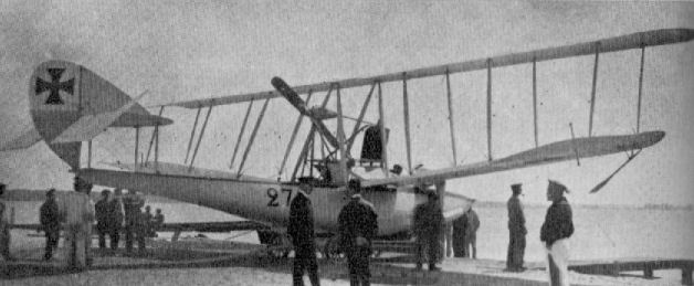
Oertz W 5
Oertz W 6 Flugschoner
Engines, 2 x 240 h.p. Maybach Mb IV. Span, 200 m. (65 ft. 7 1/2 in.). Length, 14.53 m. (47 ft. 8 1/8 in.). Height, 4.78 m. (15 ft. 8 1/4 in.). Area, 162.7 sq.m. (1,757 sq.ft.). Weights: Empty, 3,780 kg. (8,316 lb.). Loaded, 5,030 kg. (11,066 lb.). Speed, 115-118 km.hr. (71.825-73.875 m.p.h.). At a later date mid-wing ailerons were fitted to the rear pair of wings to improve lateral control.
Engines, 2 x 240 h.p. Maybach Mb IV. Span, 200 m. (65 ft. 7 1/2 in.). Length, 14.53 m. (47 ft. 8 1/8 in.). Height, 4.78 m. (15 ft. 8 1/4 in.). Area, 162.7 sq.m. (1,757 sq.ft.). Weights: Empty, 3,780 kg. (8,316 lb.). Loaded, 5,030 kg. (11,066 lb.). Speed, 115-118 km.hr. (71.825-73.875 m.p.h.). At a later date mid-wing ailerons were fitted to the rear pair of wings to improve lateral control.
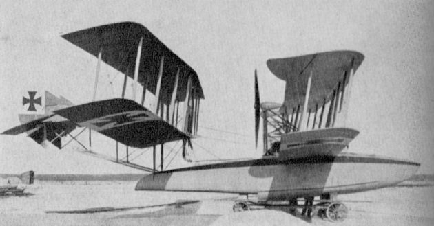
Oertz W 6 Flugschoner
Oertz W 8
After the Flugschoner, which was a tandem wing biplane, more normal wingtip floats were used and the wings themselves of conventional layout. The later aircraft were designed for the 260 h.p. Argus As IV engine, but this never materialised in time, and they were fitted with airship Maybachs of some 240 h.p. and still managed to give a performance in excess of the estimated figures, later in the war the firm was absorbed into the Hansa Brandenburg concern.
Engine, 240 h.p. Maybach Mb IV. Span, 19.6 m. (64 ft. 3 3/4 in.). Length 10.7 m. (35 ft. 1 1/4 in.). Height, 3.54 m. (11 ft. 7 1/8 in.). Area, 70 sq.m. (756 sq.ft.). Weights: Empty, 1,584 kg. (3,484 lb.). Loaded, 2,225 kg. (4,895 lb.). Speed, 136-140 km.hr. (85-87.5 m.p.h.). Climb, 2,000 m. (6,560 ft.) in 21 min.
Otto Pusher Biplane
Although many machines were built by the Otto firm of Munich before the war, Gustav Otto was plagued by ill health and undertook little work after hostilities commenced, except to build some L.V.G.s under licence. The firm was liquidated late in 1916, and its assets were taken over by B.F.W.
Although many machines were built by the Otto firm of Munich before the war, Gustav Otto was plagued by ill health and undertook little work after hostilities commenced, except to build some L.V.G.s under licence. The firm was liquidated late in 1916, and its assets were taken over by B.F.W.

Otto B 100 h.p. Rapp (1914)
Otto C I (1915)
A disused airframe on public display. Note kink in ailerons to give wash-out, as on L.V.G. machines. Engines, 150 h.p. Benz Bz III. Span, 14.5 m. (47 ft. 7 in.). Weights: Empty, 915 kg. (2,013 lb.). Loaded, 1,500 kg. (3,300 lb.). Armament, one Parabellum machine-gun in front cockpit.
A disused airframe on public display. Note kink in ailerons to give wash-out, as on L.V.G. machines. Engines, 150 h.p. Benz Bz III. Span, 14.5 m. (47 ft. 7 in.). Weights: Empty, 915 kg. (2,013 lb.). Loaded, 1,500 kg. (3,300 lb.). Armament, one Parabellum machine-gun in front cockpit.
Otto C II
This machine was the last type built before the firm went into liquidation. It was a conventional two-seater of wood and fabric construction. Engine, 160 h.p. Mercedes D III. Span, 13.4 m. (43 ft. 11 5/8 in.). Weights: Empty, 829 kg. (1,823 lb.). Loaded, 1,329 kg. (2,924 lb.).
This machine was the last type built before the firm went into liquidation. It was a conventional two-seater of wood and fabric construction. Engine, 160 h.p. Mercedes D III. Span, 13.4 m. (43 ft. 11 5/8 in.). Weights: Empty, 829 kg. (1,823 lb.). Loaded, 1,329 kg. (2,924 lb.).
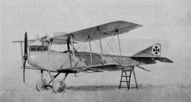
Otto C II
Pfalz A I
Used for reconnaissance purposes during the early months of the war, the parasol-winged Pfalz A I was no more than a copy of the Morane-Saulnier Type L, which had been manufactured under licence before the war. Of interest are the two celluloid panels in the fuselage sides to give added visibility from the cockpit. Engine, 80 h.p. Oberursel U O. Span, 11.2 m. (36 ft. 9 in.). Length, 6.9 m. (22 ft. 7 3/4 in.). Height, 3.4 m. (11 ft. 1 7/8 in.). Area, 18 sq.m. (194 sq.ft.). Weights: Empty, 365 kg. (803 lb.). Loaded 595 kg. (1,309 lb.). Speed, ca. 135 km.hr. (84.35 m.p.h.). Climb, 800 m. (2,624 ft.) in 6 min. Duration, 4 hr.
N.B. A single aircraft, fitted with 100 h.p. Oberursel engine, was designated A II and was developed into E III.
Pfalz E III
The Pfalz E III of 1915 was simply an armed, single-seat version of the A II, a Spandau gun being fitted to fire through the propeller. It is improbable that many were built. Engine, 100 h.p. Oberursel U I. Span, 11.2 m. (36 ft. 9 in.), length, 6.85 m. (22 ft. 5 3/4 in.). Height, 3.4 m. (11 ft. 1 7/8 in.). Area, 18 sq.m. (194 sq.ft.). Weights: Empty, 445 kg. (979 lb.). Loaded, 705 kg. (1,551 lb.). Speed, ca. 150 km.hr. (93.75 m.p.h.). Climb, 1,000 m. (3,280 ft.) in 3 min. Armament, one fixed Spandau machine-gun.
Pfalz E I and E IV
Some time before the First World War the Pfalz Flugzeug-Werke, founded in July 1913, had been financed through the Bavarian Government in an endeavor to ensure it had some control of the equipment its flying services would use. The factory, which was established at Speyer am Rhein, was in the hands of the three Eversbusch brothers, Alfred, Walter and Ernst (until the untimely death of Walter in a flying accident on 1st June 1916), who not only designed but also tested the machines they built.
Initial product of the firm was a pusher biplane, under an Otto license, which was fitted with a 100 h.p. Rapp motor. Subsequently a license was obtained from the French Morane-Saulnier firm to manufacture their type "H" shoulder wing and type "L" parasol monoplanes, which latter type, with the application of the military designation, became the Pfalz A.I fitted with 80 h.p. Oberursel (Gnome license) rotary engine and the A.II when the 100 h.p. Oberursel was installed. These machines were used in 1914 for reconnaissance and photographic work.
The Pfalz E.I was a shoulder-wing monoplane (actually a license-built Morane-Saulnier type "H", slightly modified) with a rotary engine. Helmut Hirth, a well-known figure in German flying circles before the First World War, was nearly court-martialed for refusing to fly it. However, not all pilots held it in such poor esteem, for one who flew it with enthusiasm was the bespectacled Kissenberth. At first the type was used upon unarmed scouting duties (Kavallerie Flugzeug), but with the success of the Fokker synchronizing gear in 1915, a similar installation was tried on this Pfalz built monoplane, which then went into production as the Pfalz E.I. Some sixty examples were constructed before the next variant was produced. This was the Pfalz E.II, which was little more than an E.I with a 100 h.p. Oberursel engine fitted; the armament, consisting of a single machine-gun, remained the same. The E.III, which next appeared, was not strictly in the same lineage, as it was nothing more than the A.II parasol type now fitted with a single forward-firing machine-gun, and very few were built, only four being at the Front in April 1916.
Next of this line of machines to appear was the Pfalz E.IV, in which model the airframe was strengthened and adapted to take the twin-row 160 h.p. Oberursel U.III engine. Only twenty-four machines of this type were built. As was the case with the Fokker E.IV, the engine was not too reliable, and it did not produce the improvement in performance that was anticipated. The E.V was little more than a standard E.II airframe modified to take the 100 h.p. Mercedes D.I engine with a car-type nose radiator. It was a good machine, but became available too late; twenty aircraft were ordered, but it is not certain all were completed.
Pfalz E.Is and E.IIs, which were the main production aircraft, were allocated in twos and threes to the Bavarian Fl. AN. units to protect and escort their less-nimble two-seater brethren. Due to their great similarity in appearance to the Fokker monoplanes, the Pfalz machines automatically became "Fokkers" to their Allied opponents; indeed, it was only through the shape of their steering surfaces that the types could be positively identified; they differed little in size and weight.
In contrast, the Pfalz monoplane differed considerably structurally from the Fokker product, insofar as it had a completely wooden airframe instead of the welded steel-tube fuselage of the Fokker. The fuselage was a simple rectangular-section braced box-girder structure, based on four spruce longerons which tapered to a horizontal knife-edge aft. The forward panels back to the cockpit were covered with plywood sheet, that on the top decking being curved to the same radius as the engine cowling; the remainder of the fuselage was covered with fabric. Engines were mounted with back bearer plates and housed in horse-shoe style cowlings, which were cut away to the bottom longerons to allow free escape of exhaust. On the E.IV, which had the larger two-row engine, the cowling differed in almost completely enclosing the motor, yet being fretted with large ovoid vent apertures.
There were no fin surfaces in the tail assembly. The tubular spar of the balanced elevators served also as the axis and was mounted through the tubular sternpost. The balanced rudder was hinged to the sternpost and to the inverted steel-tube pylon which served as the anchorage for the ash tailskid. All tail surfaces were covered with fabric and were of approximate trapezoidal shape.
The fabric-covered wing was of constant chord, with angularly raked tips and, in view of the warp control, was of necessity a flexible structure. Of conventional two-spar layout, the front spar was rigidly braced by cables running from a pylon in front of the cockpit to the compression tube anchorages, and from the underneath to a similar pylon between, and forming part of, the undercarriage chassis. The warp control cables were connected to actuating cranks at the base of a pylon underneath the cockpit and ran out to the underside of the rear spar. They then ran from the top surface over a pulley wheel in the top pylon, thereby completing the return linkage.
Although apt to look complicated, the undercarriage was a simple vee-type chassis which additionally incorporated the inverted bracing pylon between the front legs where it joined the center of the straight-through axles. The undercarriage was considerably raked forward, even the front legs, which gave the machine good stability when taxiing and dampened any tendency to nose over occasioned by the extremely sensitive elevator control.
As was the case with the Fokker monoplanes, more efficient and powerful biplanes were soon to come into service, and the operational life of the Pfalz E types was comparatively short on the Western Front, although they continued to serve on the Eastern Front and also in a training capacity. An unusual feature in the finish of the Pfalz monoplanes was the painting of the national insignia on all four elevator surfaces in addition to the usual locations, which probably stemmed from the firm's independence of the Flugzeugmeisterei controls.
Description: Single-seat fighting scout.
Manufacturer: Pfalz Flugzeug-Werke G.m.b.H. Speyer am Rhein (Pfal.)
E I E.II E.IV
Power Plant: 80 h.p. Oberursel U.O 100 h.p. Oberursel U.I 160 h.p. Oberursel U. III
9-cylinder rotary engine 9- cylinder rotary engine 14- cylinder rotary engine
Dimensions:
Span 9.26 m. (30 ft. 4 5/8 in.) 10.2 m. (33 ft. 5 5/8 in.) 10.2 m. (33 ft. 5 5/8 in.)
Length 6.3 m. (20 ft. 8 in.) 6.45 m. (21 ft. 2 in.) 6.6 m. (21 ft. 7 7/8 in.)
Height 2.55 m. (8 ft. 4 3/8 in.)
Area 14 sq.m. (151.2 sq.ft.) 16 sq.m. (172.8 sq. ft.) 16 sq.m. (172.8 sq. ft.)
Weights:
Empty 345 kg. (759 lb.) 410 kg. (902 lb.) 471 kg. (1,036 lb.)
Loaded 535 kg. (1,177 lb.) 620 kg. (1,364 lb.) 694 kg. (1,526 lb.)
Performance:
Max speed 145 km.h. (90.6 m.p.h.) 150 km.h. (93.75 m.p.h.) 160 km.h. (100 m.p.h.)
Climb to
800 m. 3 min. 2.75 min. 2 min.
2,000 m. 12 min. 9.75 min. 8.5 min.
Duration 1 hr.
Armament: One Spandau machine-gun One Spandau machine-gun Two Spandau machine-guns
firing forward. firing forward. firing forward.
Pfalz E IV
In every way similar to the Pfalz E types covered in the main text, the E IV differed only in its being fitted with the 160 h.p. two-row Oberursel U III rotary engine. Comparatively few were built, one reliable source putting the number at twenty-four machines. Engine, 160 h.p. Oberursel U III. Span, 10.2 m. (33 ft. 5 5/8 in.). Length, 6.6 m. (21 ft. 7 7/8 in.). Height, 2.55 m. (8 ft. 4 3/8 in.). Area, 16 sq.m. (173 sq.ft.). Weights: Empty, 471 kg. (1,036 lb.). Loaded, 694 kg. (1,527 lb.). Speed, ca. 160 km.hr. (100 m.p.h.) Climb, 800 m. (2,624 ft.) in 2 min. Armament, one or two Spandau machine-guns.
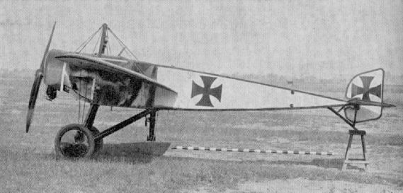
Pfalz E.I (serial 173/15)
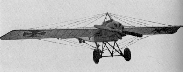
Pfalz E IV
Pfalz D Type
This aircraft was a biplane version of the E V monoplane. It was to the Walfisch format, with deep gap-filling fuselage and car-type radiator at the nose. Although not confirmed, the engine is thought to have been 100 h.p. Mercedes D I. No other data available.
This aircraft was a biplane version of the E V monoplane. It was to the Walfisch format, with deep gap-filling fuselage and car-type radiator at the nose. Although not confirmed, the engine is thought to have been 100 h.p. Mercedes D I. No other data available.
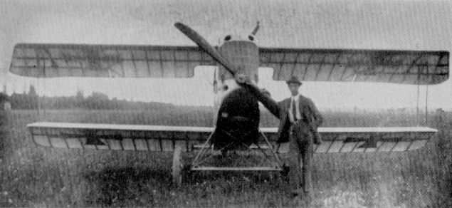
Pfalz E V
Yet another variant of the standard E type airframe, with the 100 h.p. Mercedes engine installed. Some twenty examples were built. Engine, 100 h.p. Mercedes D I. Span, 10.2 m. (33 ft. 5 3/8 in.). Length, 6.6 m, (21 ft. 7 7/8 in.). Height, 2.6 m. (8 ft. 6 3/8 in.). Area. 16 sq.m. (172 sq.ft.). Weights: Empty, 510 kg. (1,122 lb.). Loaded, 696 kg. (1,531 lb.). Speed, ca. 165 km.hr. (103.12 m.p.h.). Duration, 2 hr. Armament, one Spandau machine-gun.
Yet another variant of the standard E type airframe, with the 100 h.p. Mercedes engine installed. Some twenty examples were built. Engine, 100 h.p. Mercedes D I. Span, 10.2 m. (33 ft. 5 3/8 in.). Length, 6.6 m, (21 ft. 7 7/8 in.). Height, 2.6 m. (8 ft. 6 3/8 in.). Area. 16 sq.m. (172 sq.ft.). Weights: Empty, 510 kg. (1,122 lb.). Loaded, 696 kg. (1,531 lb.). Speed, ca. 165 km.hr. (103.12 m.p.h.). Duration, 2 hr. Armament, one Spandau machine-gun.
Pfalz D III and IIIa
With the completion of the E type monoplane orders, the Pfalz factory had no immediate project of their own, so towards the end of 1916 a contract was arranged for the L.F.G. Roland D.I to be built under license. This aircraft was followed in 1917 by construction of the Roland D.II for supply to the Bavarian Jagdstaffeln.
In the meantime the Pfalz design office had given thought to an original fighter which, in the summer of 1917, emerged as the Pfalz D.III powered with the ubiquitous 160 h.p. Mercedes D.III engine. Much of the constructional technique of the Roland fighters was used in this aircraft, although it in no way resembled them in appearance.
As has been mentioned elsewhere, the first Roland fighters had been referred to as "Haifisch" (Shark), but they were in no way as shark-like in profile as was this first original Pfalz design. The Mercedes D.III engine was closely cowled in a decidedly snoutish nose, the contour of which was initiated by the small pointed spinner on the airscrew. With such a sharp profile it was inevitable that most of the cylinder block protruded, but it was encased in removable metal panels. Apart from the metal paneling adjacent to the engine, the remainder of the fuselage was a wooden, semi-monocoque structure. The light basic framework of spruce longerons and oval ply formers was spirally wrapped, in opposing directions, with two layers of ply strip and then fabric-covered and doped. The vertical fin was an integral part of the fuselage. On the earlier production D.III the twin Spandau machine-guns were mounted inside the fuselage, with only the muzzles protruding each side of the cylinder block; later they were mounted on the decking in front of the windscreen in the more usual manner to facilitate servicing.
The angular tailplane was a wooden structure, fabric covered and of an inverted aerofoil section as an aid to more rapid dive recovery. It was undoubtedly the use of this feature that made it possible to fit an unbalanced, one-piece elevator of wooden construction. The rounded and balanced rudder was of welded steel-tube construction with fabric covering.
Of austerely angular outline, the fabric-covered wings owed something to the Nieuport - or Albatros - but without the shortcoming of the single spar lower wing featured in those two types. Although the upper wing was the greater in span and chord, both wings were of the same basic shape, with parallel chord and severely raked angular tips. The upper wing was a one-piece structure without dihedral and based on two box-spars cable braced to the compression members. A unique feature of the box-spars was the insertion of a diaphragm at all rib stations to transmit the sheer stresses across the spar, and might with advantage have been incorporated in all box-spars. Ribs were of three ply, with fretted lightening holes and softwood capping strips, and were interspaced with strip false ribs, which extended as far as the rear spar. The center-section panel, with its curved cut-out, was ply skinned and housed the flush-type Teeves and Braun radiator in the starboard side and a gravity fuel tank in the port side.
Ailerons, with characteristic wash-out, were of parallel chord with triangular balance portions and were, unusually, of wooden framing. They were operated by a crank at mid-span, which in turn was actuated by cables which ran through the lower wing. The bottom wing panels, each with 1 degree dihedral, were of the same style of construction and were joined to extremely carefully fashioned root fairings, which were built integral with the fuselage.
The center-section struts were of wood and of inverted U-pattern; interplane struts, also wood, were vee shaped and wide enough at the base to join both spars of the lower wing. A conventional vee-type undercarriage chassis was fitted and the axle and spreaders encased in a streamlined fairing. The unusual arrangement of the tailskid may be seen from the general arrangement drawing - it was sprung with elastic cord.
It was the autumn of 1917 when the Pfalz D.III got to the Front, mainly going to Bavarian Jastas and often forming a composite establishment with Albatros D.IIIs, D.Vs and Roland D.IIs. It has often been reported that the Pfalz D.III was unpopular with pilots due to inferior performance and maneuverability, but this attitude is not easily understood in the light of an Allied assessment of a D.III (4184/17) which force-landed near Bonnieul on 26th February 1918 and was put into flying trim again. It was reported that view from the cockpit was excellent in all directions, with the possible exception of approach glide, when to some extent the top wing interfered. With regard to flight characteristics, the comment was that the aircraft was stable laterally and unstable directionally and longitudinally, which doubtless meant that general maneuverability was good, although the rate of roll was perhaps not what it might have been. It was also reported as answering well to all controls - "much better than does the Albatros D.V".
In 1918 the D.IIIa, an improved version which competed at the January fighter competition, was introduced. This aircraft was fitted with the Mercedes D.IIIa motor of some 180 h.p. and had a tailplane of increased area and near semicircular profile. The tips of the lower wing were also modified to a more rounded shape to improve efficiency, otherwise the machine was substantially the same as its forebear.
According to the Inter-Allied Control Commission figures, some 600 Pfalz D.III and D.IIIa were supplied altogether, and no less than 350 were still in Front Line service in August 1918.
In being responsible to the Bavarian administration and not the German Flugmeisterei (Directorate of Aircraft Production), the Pfalz firm were often a law unto themselves, as evidenced by the fact that practically the whole of the Pfalz D.III/IIIa production had fuselages finished with aluminum dope.
Description: Single-seat fighter.
Manufacturer: Pfalz Flugzeug-Werke, G.m.b.H. Speyer am Rhein (Pfal.)
Power Plant: D.III 160 h.p. Mercedes D.III 6- cylinder in-line water-cooled engine.
D.IIIa 180 h.p. Mercedes D.IIIa
Dimensions:
Span 9.4 m. (30 ft. 10 1/8 in.)
Length 6.95 m. (22 ft. 9 3/4 in.)
Height 2.67 m. (8 ft. 9 1/8 in.)
Area 22.17 sq.m. (237.75 sq.ft.)
Weights:
Empty 1,532 lb
Loaded 2,056 lb
Performance:
Max speed at
10,000 ft. 102.5 m.p.h.
15,000 ft. 91.5 m.p.h.
Climb to
5,000 ft. 6 min. 55 sec.
10,000 ft. 17 min. 30 sec.
15,000 ft. 41 min. 20 sec.
Ceiling 17,000 ft.
Endurance 2 1/2 hr.
Armament: Two fixed Spandau machine-guns firing forward.
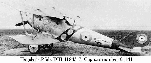
Hegeler's Pfalz D III (serial 4184/17). Capture number G.141
Albatros D V fighters taking off on patrol. A solitary Pfalz D III can also be seen in the background.

Pfalz D VI
There is no record of a D V, and the next Pfalz single-seater to appear was the extremely elegant D VI of 1917. It featured wrapped plywood fuselage technique, as handed down through the L.F.G. D II and Pfalz D III production series, the struts and wing arrangement being reminiscent of the D III also. The D VI participated in the first D types Competition at Adlershof, and when flown by Baierlein on 5th February 1918 achieved the performance figures specified below. Engine, 110 h.p. Oberursel U II. Span, 7.08m. (23 ft. 2 3/4 in.). Area, 13.3 sq.m.(149 sq.ft.). Weights: Empty. 400 kg. (880 lb.). Loaded, 606 kg. (1,334 lb.). Climb, 5,000 m. (16,400 ft.) in 25 min. Service ceiling, 5,600 m. (18,368 ft.).
There is no record of a D V, and the next Pfalz single-seater to appear was the extremely elegant D VI of 1917. It featured wrapped plywood fuselage technique, as handed down through the L.F.G. D II and Pfalz D III production series, the struts and wing arrangement being reminiscent of the D III also. The D VI participated in the first D types Competition at Adlershof, and when flown by Baierlein on 5th February 1918 achieved the performance figures specified below. Engine, 110 h.p. Oberursel U II. Span, 7.08m. (23 ft. 2 3/4 in.). Area, 13.3 sq.m.(149 sq.ft.). Weights: Empty. 400 kg. (880 lb.). Loaded, 606 kg. (1,334 lb.). Climb, 5,000 m. (16,400 ft.) in 25 min. Service ceiling, 5,600 m. (18,368 ft.).
Pfalz D VII
Two versions of the Pfalz D VII were built and differed only in engine installation and cowling arrangement and in that the second machine, with the Oberursel engine, had overhung, balanced ailerons.
Engine, 160 h.p. Siemens-Halske Sh III geared rotary. Span, 7.52 m. (24 ft. 8 1/8 in.). Length, 5.65 m. (18 ft. 6 1/2 in.). Height, 2.85 m. (9 ft. 4 1/8 in.) Area, 17.2 sq.m. (186 sq.ft.). Weights: Empty, 520 kg. (1,144 lb.). Loaded, 715 kg. (1,573 lb.). Speed, 190 km.hr. (118.75 m.p.h.) at 4,000 m. Climb, 6,000 m. (19,680 ft.) in 25.25 min.
Engine, 160 h.p. Oberursel U III rotary. Span, 8.1 m. (26 ft. 7 in.). Length, 5.55 m. (18 ft. 2 5/8 in.). Height, 2.7m. (8 ft. 10 1/4 in.). Area, 17.2 sq.m. (186 sq.ft.). Weights: Empty, 483.5 kg. (1,064 lb.). Loaded, 738 kg. (1,624 lb.). Duration, l 1/2 hr. (both types). Armament, twin Spandau machine-guns (both types).
Pfalz D VIII
No less than three variants of the D VIII existed, powered with 160 h.p. Siemens-Halske, 160 h.p. Oberursel and 140 h.p. Goebel, the latter version differing in having horn-balanced ailerons and "N" format interplane struts. The machines were built early in 1918 and participated in the second D types Competition. A small production order was given for the Siemens-engined variant. A total of forty machines were completed; some nineteen were at the Front by August 1918 undergoing operational assessment with Jastas 29 and 56.
Engine, 160 h.p. Siemens-Halske Sh III, 160 h.p. Oberursel U III, 140 h.p. Goebel Goe III. Span, 7.52 m. (24 ft. 8 1/8 in.). (8.1 m. 157/18). Length, 5.65 m. (18 ft. 6 1/2 in.). Height, 2.75 m. (9 ft. 0 1/8 in.). Area, 17.2 sq.m. (186 sq.ft.). Weights: Empty, 543 kg.(1,195 lb.); loaded,738 kg. (1,624 lb.), Sh III variant. Empty 495.6 kg. (1,090 lb.); Loaded, 685.6 kg. (1,508 lb.), U III variant. Empty, 552.7 kg. (1,216 lb.); Loaded, 722.7 kg. (1,590 lb.), Goe III variant. Climb, 1,000 m. (3,280 ft.) in 1.9 min., 6,000 m. (19,680 ft.) in 25 min., Sh III variant; 1,000 m. (3,280 ft.) in 21 min., 5,000 m. (16,400 ft.) in 25.5 min., U III variant. Duration, 1 1/2 hr. Armament, twin Spandau machine-guns.
Pfalz Dr I
This stocky triplane fighter stemmed from the D VII and in fact was virtually a D VII fitted with triplane wings. Official type test was in October 1917. Reports on the number of these triplanes built vary, but the most reliable figure seems to indicate that no more than ten were constructed. The performance did not offer sufficient improvement over that of the Fokker triplane. Engine, 160 h.p. Siemens-Halske Sh III. Span, 8.55 m. (28 ft. 0 5/8 in.). Length, 5.5 m. (18 ft. 0 5/8 in.). Height, 2.76 m. (9 ft. 0 5/8 in.). Area, 17.2 sq.m. (186 sq.ft.). Weights: Empty, 510 kg. (1,122 lb.). Loaded, 705 kg. (1,551 lb.). Climb, 1,000 m. (3,280 ft.) in 1.7 min., 3,000 m. (9,840 ft.) in 6.2 min. Armament, twin Spandau machine-guns.
This stocky triplane fighter stemmed from the D VII and in fact was virtually a D VII fitted with triplane wings. Official type test was in October 1917. Reports on the number of these triplanes built vary, but the most reliable figure seems to indicate that no more than ten were constructed. The performance did not offer sufficient improvement over that of the Fokker triplane. Engine, 160 h.p. Siemens-Halske Sh III. Span, 8.55 m. (28 ft. 0 5/8 in.). Length, 5.5 m. (18 ft. 0 5/8 in.). Height, 2.76 m. (9 ft. 0 5/8 in.). Area, 17.2 sq.m. (186 sq.ft.). Weights: Empty, 510 kg. (1,122 lb.). Loaded, 705 kg. (1,551 lb.). Climb, 1,000 m. (3,280 ft.) in 1.7 min., 3,000 m. (9,840 ft.) in 6.2 min. Armament, twin Spandau machine-guns.
Pfalz Experimental Triplane
No data is available on this 1917 triplane version of the Pfalz D III, which is reported never to have flown. Engine, 160 h.p. Mercedes D III.
No data is available on this 1917 triplane version of the Pfalz D III, which is reported never to have flown. Engine, 160 h.p. Mercedes D III.
Pfalz Experimental D Type
Although not confirmed, this machine is thought to be the prototype for the D XII. It may be seen to be a combination of D III type fuselage and D XII wing cellule, with ear-type radiators mounted on the fuselage sides between the wings. Engine, 180 h.p. Mercedes D IIIa.
Pfalz D XII
After a fairly long series of prototype single-seaters, both biplane and triplane, the next Pfalz fighter to see anything like quantity production was the D.XII, which appeared at the June 1918 fighter trials at Adlershof, in both Mercedes D.IIIa and B.M.W. III engined models. Its appearance had obviously been influenced by the Fokker D.VII, but in construction it could not have differed more radically. As was the case with all competing machines, the D.XII was flown by crack pilots from the Front Line Jastas. It is known that at least two expressed approval of the Pfalz machine, Ernst Udet and Hans Weiss, and it has been inferred they received some monetary gain from Otto Kahn, who was responsible for the Pfalz finances. This may or may not have been true, nevertheless a production order was placed to bolster Fokker D.VII supplies, which were not available in the required quantities due to the high rate of attrition of fighter aircraft at this late period of the war. Paradoxically, although it differed so drastically in appearance from its precursor, the D.III, in constructional methods it was greatly similar.
Much of the propaganda which had extolled the Fokker product as a "world beater" had led all German fighter pilots into wanting a D.VII. When the practically unheralded Pfalz D.XII began to appear in the Jastas from August in 1918 pilots regarded it askance. Nevertheless it was an extremely good aeroplane, equal to the Fokker D.VII in many respects, and in diving capacity, at least, it was superior. Pilots soon adapted themselves to it, and even began to like it. Unfortunately its double-bay rigging, although ensuring an excellent strength factor, was understandably unpopular with ground crews, due to the additional work it made.
The pleasingly contoured fuselage, like the D.III, was a semi-monocoque based on a framework of spruce longerons and plywood formers. It was spirally wrapped with two layers of three-ply strip about 31 in. wide and applied in opposite directions, being finally covered with fabric and doped. The Mercedes D.IIIa engine was installed with a frontal "car" type radiator and mounted on top of the front end of the engine bearers. The cylinder block was cowled in with metal side panels above engine bearer level, which had adjustable cooling slots punched in them. The collector manifold exhausted sideways to starboard. A small metal chin cowling faired off the underside of the radiator, otherwise the fuselage was all wood, and tapered gracefully to a vertical knife-edge aft.
The fin surfaces of the tail were the opposite of those of the D.III, the vertical fin now being of welded steel tube and fabric covered, while the rounded tailplane was a wooden structure of symmetrical section and covered with a thin plywood skin. The spars went right through the fuselage, and the tailplane could not be adjusted for incidence, neither could it be removed! Control surfaces were all of welded steel tube and fabric covered. The balanced rudder continued the rounded profile of the fin, and the split elevators were generous in area and of approximate rectangular shape, with large overhung horn-balance portions.
Both wings were of equal parallel chord and only slightly raked at the tips; the upper wing was of slightly greater span. Construction was almost identical in detail to that of D.III wings, although an additional solid spruce spar ran through between the rear main spar and the trailing-edge wire. To this the ailerons were hinged on the upper wing; these were of steel-tube framing and of extremely high aspect ratio; overhung balance portions made them light to control and imparted a very good rate of roll to the D.XII. Another addition to the top wing as compared with the earlier machine was the inclusion of additional false rib strips extending only to the front main spar and spaced between the main rib and the false rib strip that extended back to the rear spar. Again the upper wing was a one-piece structure without dihedral and the lower wings were attached to the carefully molded root fairings with 1 1/2 degrees of dihedral.
Bracing of the wing cellule was of great robustness. All struts were of streamlined steel tube, those of the center-section being "M"-shaped and the four sets of slightly splayed interplane struts of "N" pattern. A conventional vee-type undercarriage chassis of streamlined steel tube was fitted, and the axle had spiral steel-spring shock absorbers. A stout, steel-shod, ash tailskid was mounted forward of the sternpost and internally sprung with steel springs.
Rudolph Stark, who commanded the Bavarian Jagdstaffel 35, which together with Jastas 23, 32 and 34 formed the Bavarian Jagdgeschwader IV commanded by Edouard von Schleich, has reported that when Pfalz D.XIIs were received by his unit early in September 1918, to replace the war-weary Albatros D.Vas and Pfalz D.IIIs, they were initially looked upon by the pilots with dismay. He nevertheless goes on to say that when the pilots had thoroughly familiarized themselves with the type-those that survived those hectic days long enough to do so, that is-were able to give a good account of themselves and to cope with the Camels, S.E.s and Dolphins of the British without undue disadvantage.
Undoubtedly the Pfalz D.XII's worst enemy was the eulogistic propaganda that had surrounded the earlier Fokker D VII, coupled with its own unannounced, almost mysterious, debut. While the Fokker product had been lauded to the skies, the Pfalz was a completely unknown quantity to pilots, and therefore at an immediate disadvantage. There is no doubt it was a good machine: well designed and carefully constructed. If the war had lasted longer it would most likely have emerged from the shadow of the Fokker D.VII to stand upon its own merits.
The Pfalz D.XII was supplied to Jastas 23, 32, 34, 35, 64, 65, 66, 77, 78 and 81, as well as to home-defense fighter units. By October 1918. there were 180 Pfalz D.XIIs in service on the Western Front.
Description: Single-seat fighter
Manufacturer: Pfalz Flugzeug-Werke G.m.b.H. Speyer am Rhein (Pfal.)
Power Plant: One 160 h.p. Mercedes D.IIIa 6 cylinder in-line water-cooled engine developing maximum 180 h.p.
Dimensions:
Span 9.0 m. (29 ft. 6 3/8 in.)
Length 6.35 m. (20 ft. 10 in.)
Height 2.7 m. (8 ft. 10 1/4 in.)
Area 21.7 sq.m. (236.3 sq.ft.)
Weights:
Empty 716 kg. (1,571 lb.)
Loaded 897 kg. (1,973.4 lb.)
Performance:
Max speed 170 km.hr (106.25 m.p.h.)
Climb
1,000 m. (3,280 ft.) in 3.4 min, (2.7 min, with B.M.W. III)
5,000 m. (16,400 ft.) in 29.9min. (21.0 min. with B.M.W. III)
Ceiling 18,500ft
Endurance 2 1/2 hr.
Armament: Two fixed Spandau machine-guns firing forward.
Pfalz D XIV
This experimental machine was basically a slightly enlarged D XII with high compression 200 h.p. Benz Bz IV u. motor. It could be distinguished visually from the D XII by the larger vertical fin. Engine, 200 h.p. Benz Bz IV u. Span, 10.0 m. (32 ft. 9 3/4 in.). Length, 6.32 m. (20 ft. 8 3/4 in.). Height, 2.7 m. (8 ft. 10 1/4 in.). Area, 25.43 sq.m. (275 sq.ft.). Weights: Empty, 833 kg. (1,833 lb.). Loaded, 1,032 kg. (2,270 lb.). Speed, 180 km.hr. (112.5 m.p.h.) at 4,000 m. (13,120 ft.). Climb, 1,000 m. (3,280 ft.) in 3 min. 5,000 m. (16,400 ft.) in 26.1 min. Duration, 1 1/2 hr. Armament, twin Spandau machine-guns.
This experimental machine was basically a slightly enlarged D XII with high compression 200 h.p. Benz Bz IV u. motor. It could be distinguished visually from the D XII by the larger vertical fin. Engine, 200 h.p. Benz Bz IV u. Span, 10.0 m. (32 ft. 9 3/4 in.). Length, 6.32 m. (20 ft. 8 3/4 in.). Height, 2.7 m. (8 ft. 10 1/4 in.). Area, 25.43 sq.m. (275 sq.ft.). Weights: Empty, 833 kg. (1,833 lb.). Loaded, 1,032 kg. (2,270 lb.). Speed, 180 km.hr. (112.5 m.p.h.) at 4,000 m. (13,120 ft.). Climb, 1,000 m. (3,280 ft.) in 3 min. 5,000 m. (16,400 ft.) in 26.1 min. Duration, 1 1/2 hr. Armament, twin Spandau machine-guns.
Pfalz D XV
Last of the Pfalz single-seaters was the D XV, which was officially type tested on 4th November 1918. It departed from previous practice in having the ply-skinned fuselage slung between the wings and all flying and landing wires deleted. The Inter-Allied Control Commission tabulation on the Pfalz-Werke credits 180 of these aircraft being built, but the figure seems not to have been substantiated. It seems likely that this was the number initially projected. Both 180 h.p. Mercedes D IIIa and 185 h.p. B.M.W. IIIa engined versions existed. Span, 8.6 m. (28 ft. 2 5/8 in.). Length, 6.5 m. (21 ft. 4 in.). Height, 2.7 m. (8 ft. 10 1/4 in.). Weights: Empty, 745 kg. (1,693 lb.), Merc; 738 kg. (1,624 lb.), B.M.W. Loaded, 925 kg. (2,035 lb.), Merc; 918 kg. (2,020 lb.), B.M.W. Speed, ca. 200 km.hr. (125 m.p.h.). Climb, 1,000 m. (3,280 ft.) in 2 min., 6,000 m. (19,680 ft.) in 22.2 min. Armament, twin Spandau machine-guns.
Last of the Pfalz single-seaters was the D XV, which was officially type tested on 4th November 1918. It departed from previous practice in having the ply-skinned fuselage slung between the wings and all flying and landing wires deleted. The Inter-Allied Control Commission tabulation on the Pfalz-Werke credits 180 of these aircraft being built, but the figure seems not to have been substantiated. It seems likely that this was the number initially projected. Both 180 h.p. Mercedes D IIIa and 185 h.p. B.M.W. IIIa engined versions existed. Span, 8.6 m. (28 ft. 2 5/8 in.). Length, 6.5 m. (21 ft. 4 in.). Height, 2.7 m. (8 ft. 10 1/4 in.). Weights: Empty, 745 kg. (1,693 lb.), Merc; 738 kg. (1,624 lb.), B.M.W. Loaded, 925 kg. (2,035 lb.), Merc; 918 kg. (2,020 lb.), B.M.W. Speed, ca. 200 km.hr. (125 m.p.h.). Climb, 1,000 m. (3,280 ft.) in 2 min., 6,000 m. (19,680 ft.) in 22.2 min. Armament, twin Spandau machine-guns.

Rex Single-Seater 1915
Rex Single-Seat Scout
This dainty little scout-type single-seater was built by the Flugmaschine Rex G.m.b.H. early in 1916 and, as may be seen, was an orthodox aircraft of wood and fabric construction. It is reported as having been based on the British Bristol Scout. As far as is known, only this single machine serialled 6/16, was built. Engine, 80 h.p. Oberursel U O.
This dainty little scout-type single-seater was built by the Flugmaschine Rex G.m.b.H. early in 1916 and, as may be seen, was an orthodox aircraft of wood and fabric construction. It is reported as having been based on the British Bristol Scout. As far as is known, only this single machine serialled 6/16, was built. Engine, 80 h.p. Oberursel U O.
The D 17 is undoubtedly based on the Nieuport formula. It is said to have been built for Lt. Voss and was powered with 100 h.p. Hansen engine.
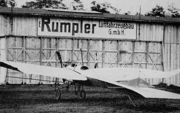
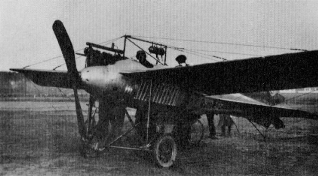
Rumpler Eindecker
Rumpler Eindecker
Although a pre-war design, as were all Taube types, many Rumpler Taubes saw service use during the early months of the war on reconnaissance duties. Not strictly a true Taube, the machine illustrated above was photographed at Karlsruhe in March 1912, and veteran airman Hellmuth Hirth occupies the rear cockpit, with Lt. Schoeller in front. Engine, 100 h.p. Mercedes D I.
Although a pre-war design, as were all Taube types, many Rumpler Taubes saw service use during the early months of the war on reconnaissance duties. Not strictly a true Taube, the machine illustrated above was photographed at Karlsruhe in March 1912, and veteran airman Hellmuth Hirth occupies the rear cockpit, with Lt. Schoeller in front. Engine, 100 h.p. Mercedes D I.
Rumpler 4B 11
Virtually a 4A 13 type land machine mounted on a float chassis and used during 1914 for reconnaissance work. The ungainly size and pontoon shape of the floats may be noted. Aircraft of this type were allocated Navy Numbers 49-51 and 86-90. Engine, 100 h.p. Benz Bz I. Span, 13.0 m. (42 ft. 7 7/8 in.). Length, 9.8 m. (32 ft. 1 7/8 in.). Height, 3.52 m. (11 ft. 6 5/8 in.) Weights: Empty, 810 kg. (1,782 lb.). Loaded, 1,030 kg. (2,266 lb.). Sped, 130 km.hr. (81.25 m.p.h.).
Rumpler 4B 12
A development of the 4B 11 and a seaplane version of the 4A 14. Some eighteen of these aircraft were built and in use in 1915, mainly on reconnaissance and coastal patrol. Navy Numbers: 101-110, 241-243 and 436-440. Engine, 150 h.p. Benz Bz III. Span, 14.5 m. (47 ft. 7 in.). Length, 9.6 m. (31 ft. 6 in.). Height, 3.6 m. (11 ft. 9 3/4 in.). Weights: Empty, 960 kg. (2,112 lb.). Loaded, 1,280 kg. (2,816 lb.).
Rumpler 4B 13 was the same aircraft but powered with 160 h.p. Gnome rotary.
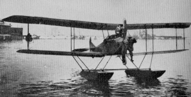
Rumpler 4B 11
Rumpler 4E
This flying-boat was built in 1914. Engine, 120 h.p. Austro-Daimler. Span, 15.7 m. (51 ft. 4 3/4 in.). Length, 8.94 m. (29 ft. 0 in.). Height, 3.4 m. (11 ft. 0 in.).
This flying-boat was built in 1914. Engine, 120 h.p. Austro-Daimler. Span, 15.7 m. (51 ft. 4 3/4 in.). Length, 8.94 m. (29 ft. 0 in.). Height, 3.4 m. (11 ft. 0 in.).
Rumpler B I (4A)
Probably the first Rumpler biplane, the B I was built in 1914 and used for reconnaissance work and training duties. Engine, 100 h.p. Mercedes D I. Span, 13.0 m. (42 ft. 7 7/8 in.). Length, 8.4 m. (27 ft. 6 3/4 in.). Height, 3.1 (10 ft. 2 1/8 in.). Weights: Empty, 750 kg. (1,650 lb.). Loaded, 970 kg (2,134 lb.). Speed, 145 km.hr. (90.625 m.p.h.).
Rumpler 4A 13
Developed from the B I, the 4A 13 differed in having a comma-type balanced rudder and radiators located on the fuselage sides. Engine, 100 h.p. Mercedes D I. Span, 14.5 m. (47 ft. 7 in.). Length, 8.4 m. (27ft. 6 3/4 in). Height, 3.1 m. (10 ft. 6 in.) Weights: Empty, 780 kg. (1,716 lb.). Loaded, 1,064 kg. (2,341 lb.). Speed, 145 km.hr. (90.625 m.p.h.). The Rumpler 4A 14 was a similar machine but powered with 150 h.p. Benz engine which gave loaded weight of 1,130 kg. (2,486 lb.). No photo available.
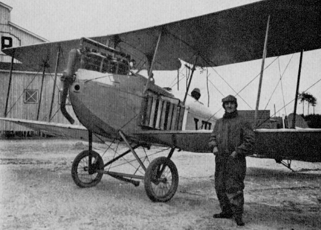
Rumpler 4A 13
Rumpler C I and Ia
One of the most successful and best liked of the newly introduced C type armed two-seaters which appeared during 1915 was the C.I of the Rumpler Flugzeug-Werke. Previously, unarmed B types had been manufactured on a small scale, but the efficiency of the 160 h.p. Mercedes engined C.I on its debut assured production in considerable quantity. At first equipped only with a Parabellum machine-gun for the observer, the armament was later reinforced by the addition of a Spandau machine-gun for the pilot, mounted on the port side firing forward. The Rumpler C.I and la, (the latter machine being no more than a C.I fitted with a 180 h.p. Argus engine) entered widespread service on all Fronts. By October 1916 there were some 250 C.Is and C.Ias in service. They were used as general-purpose types, and when they became outclassed on the Western Front they served in the Salonika, Palestine and Macedonian theatres during the 1917 period. They were also used on training duties in Germany right up to the end of the war. In fact, during 1918 a special trainer version with dual control was developed by the Bayerische Rumpler-Werke. This version was powered with a 150 h.p. Benz engine and did not have a gun-ring installation in the rear cockpit.
In construction the Rumpler C.I was endowed with some novel features, the main one being the compound structural mediums used in the fuselage framework. Installation of the 160 h.p. Mercedes D III engine in the nose was in orthodox fashion: cylinder block protruding; curved metal panels arcing in from the upper longerons to enclose the crankcase; rounded metal nose fairing through which the propeller shaft extended. A largish, streamlined collector manifold was fitted on the starboard side, from which climbed a raked-back "chimney" exhaust pipe which ejected over the top wing. The fuselage was a normal slab-sided, braced box-girder structure with a rounded top decking, tapering to a vertical knife-edge aft. In the structural material used it differed from usual practice. The four longerons were of pine towards the rear and of ash forward, being spliced in the region of the cockpits. Aft of the rear cockpit the vertical and lateral spacers were of ash, but forward of that point steel tube was employed. There was a three-ply sheet panel each side of the nose, extending as far aft as the front center-section strut; the remainder of the fuselage was covered with fabric.
Tail surfaces were of welded steel tube throughout and fabric covered. All fin surfaces, which were braced with light streamlined steel struts, were of triangular profile and of flat plate section. The unbalanced, divided elevators were of inverse taper and rounded off the contour of the tailplane. The rudder, likewise unbalanced, was pleasingly curved and set a pattern which was to remain little altered in the subsequent operational Rumpler two-seaters.
Of two-bay format, the wings were slightly tapered and based on the conventional two-spar system, with cable-braced steel-tube compression members. They incorporated some 5' of sweep on the leading edge and a minute amount (16 mm.) of negative stagger. Both wings were of parallel chord, which differed by something less than 2 in.; tips were angularly raked, with fairly well-rounded corners. Ribs were of ply, with softwood capping strips, and interspaced with false ribs extending back only to the front spar. A solid trailing-edge member was used, hence the Rumpler C.I did not feature a scalloped outline. Unbalanced ailerons of inverse taper and characteristic wash-out were hinged to false spars at the upper wingtips only. They were operated by a mid-span crank lever which was actuated by cables fed through, and then vertically up from, the lower wing. A generous, curved, cut-out in the center-section improved the observer's field of view; likewise cut-outs of identical profile in the lower wing roots. Both wings were rigged with dihedral, and the upper wing, in two panels, was joined to a trestle-type center-section cabane of streamlined steel tube. Rumpler C.Is were one of the first C types to feature the frontal (Stirnkuhler) radiator mounted at the leading edge of the center-section. The Rumpler's installation was exceedingly neat, being recessed into the wing panel so as to lie flush with the leading edge. The semicircular section also made for neatness in appearance and reduced the "blind spot" area, which was a considerable shortcoming with rectangular radiators.
As in the center-section struts, interplane struts were also of streamlined steel tube with cable bracing. A single drag wire ran from the top of the front undercarriage strut to the top of the rear inboard interplane strut. The same medium was used for the undercarriage, which had the normal vee-type chassis. The rear legs were cable braced, and a claw brake was usually fitted to the center of the axle. Wheels were sprung with either spiral springs or elastic cord, according to availability. A cleanly installed ash tailskid, internally sprung and hinged just forward of the sternpost, completed the assembly.
As evidence of the continued usefulness of Rumplers it is on record that eight new C.Is were transported to Damascus in the spring of 1917 and were to play a big part in the battles which took place that year for Gaza. All enemy troop movements were observed by the Rumplers and the General Staff kept constantly informed. C.Is acted almost exclusively as couriers for the Commanding General, von Kress. When the General wished to re-deploy his troops a large white cloth, which he carried in his car, was laid out upon the ground and a Rumpler promptly landed near by and then conveyed the necessary intelligence to the subordinate commanders. In this way the Staff were able to keep the troops well under control. Bombing raids were carried out on Allied cavalry, and captured prisoners testified to the havoc wrought. Special emphasis had to be placed on visual observation in this theatre, and observers became highly skilled. Much photographic reconnaissance was almost impossible due to the deterioration of the photographic plates; the excessive heat affecting the gelatin emulsion.
Description: Two-seat general duties.
Manufacturers: Rumpler Flugzeug-Werke G.m.b.H. Johannisthal, Berlin (Ru.).
Sub-contractors: Germania Flugzeug-Werke (Germ.); Markische Flugzeug-Werke (Mark.); Hannoversche Waggonfabrik (Han.), C.Ia; Bayerische Rumpler-Werke (Bayru.) with BzIII; Albert Rinne Flugzeug-Werke (Rin.).
Power Plant: 160 h.p. Mercedes D.III 6- cylinder in-line water-cooled engine.
150 h.p. Benz Bz.III 6- cylinder in-line water-cooled engine in Bayru. C.I.
180 h.p. Argus As.III 6- cylinder in-line water-cooled engine in C.Ia.
Dimensions:
Span 12.15 m. (39 ft. 10 3/8 in.)
Length 7.85 m. (25 ft. 9 in.)
Height 3.06 m. (10 ft. 1/2 in.)
Area 35.7 sq.m. (385.6 sq.ft.)
Weights:
Empty 793 kg. (1,744.6 lb.)
Loaded 1,333 kg. (2,866.6 lb.)
Performance:
Max speed 152 km.h. (95 m.p.h.)
Ceiling 16,600 ft.
Endurance 4 hr. on 240 liters fuel (200 main, 40 gravity)
Armament: One fixed Spandau machine-gun on port side forward,
and one manually operated Parabellum machine-gun in the rear cockpit.
Small bomb load as tactically required, not exceeding approximately 100 kg.
Rumpler 5A 4
This machine, built during winter 1915/1916, was an obvious link between the C I (5A 2) and the C III (6A 5). There was a C II (5A 3) scheduled but no record of it having been built. Engine, 160 h.p. Mercedes D III. Weights: Empty, 640 kg. (1,408 lb.). Loaded, 1,120 kg. (2,464 lb.).
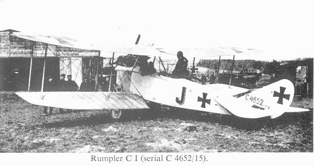
Rumpler C I (serial C4652/15).
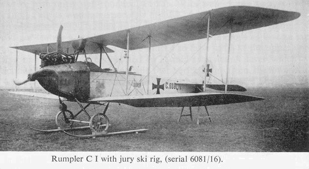
Rumpler C I with jury ski rig, (serial 6081/16).
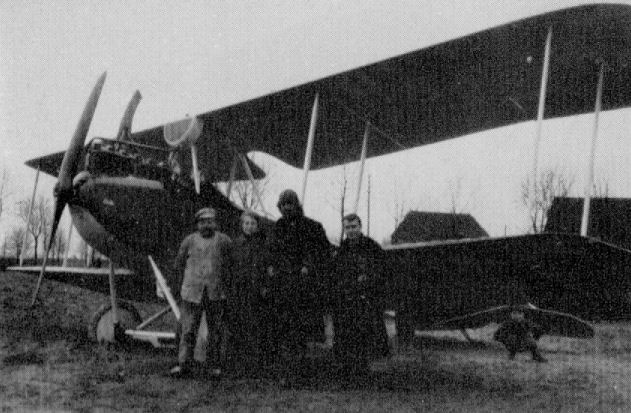
Rumpler 5A 4
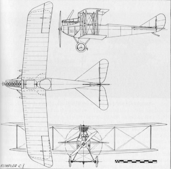
Rumpler 4A 15
This first Rumpler Grossflugzeuge appeared in March 1915 and became the prototype for the later G I. The machine made a test climb, carrying ten personnel, to an altitude of 3,200 m. on 15th March 1915, and later the same day attained a height of 1,800 m. while carrying sixteen personnel. On 17th April 1915 this prototype was destroyed. Engines, two 150 h.p. Benz Bz III. Span, 18.75 m. (61 ft. 6 1/4 in.). Length, 11.8 m. (38 ft. 8 5/8 in.).
Rumpler G I (5A 15)
The Rumpler G I went into small-scale production in 1915 after the tail surfaces had been revised. It was of conventional wood and fabric construction, and a crew of three was carried. The twin engines, which drove pusher airscrews, were neatly encased with fairings extending right down to the lower wing. Car-type radiators were mounted on the forward end of the engine nacelles. Engines, two 160 h.p. Mercedes or 150 h.p. Benz. Span, 19.28 m. (63 ft. 3 1/8 in.). Length, 11.8 m. (38 ft. 8 5/8 in.). Height, 4.0 m. (13 ft. 1 1/2 in.). Area, 78.68 sq.m. (850 sq.ft.). Weights: Empty, 1,998 kg. (4,396 lb.). Loaded, 2,938 kg. (6,574 lb.). Speed, 145 km.hr. (90.625 m.p.h.). Climb, 800 m. (2,624 ft.) in 7 min., 4,000 m. (13,120 ft.) in 2 hr. Duration, ca. 4 hr. Armament, one Parabellum machine-gun in nose cockpit.
Rumpler G II (5A 16)
This machine differed little from the G I and, as far as can be ascertained, was virtually the same aircraft fitted with more powerful 220 h.p. Benz Bz IV engines. Armament, one Parabellum machine-gun in nose cockpit and one aft of wings.
Rumpler G III (6G 2)
Final development of the Rumpler twin-engined bombers, the G III followed the previous trend, but now had the engine nacelles considerably cleaned up and mounted well clear of the lower wing. Lateral control was improved by the introduction of horn-balanced ailerons. Engines, two 260 h.p. Mercedes D IVa. Span, 19.30 m. (63 ft. 3 7/8 in.). Length, 1200 m. (39 ft. 4 1/2 in.). Height, 4.50 m. (14 ft. 9 1/4 in.). Weights: Empty, 2,295 kg. (5,049 lb.). Loaded, 3,620 kg. (7,964 lb.).
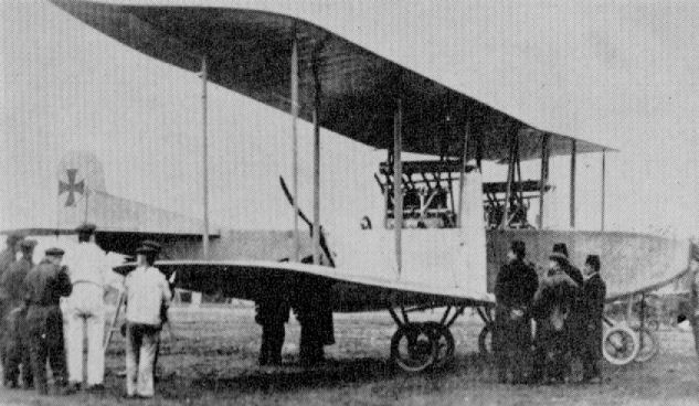
Rumpler 4A 15
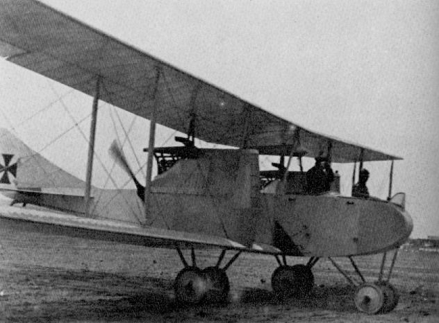
Rumpler G I (5A 15) (first version)

Rumpler G II (5A 16)
Rumpler 6A 2
This experimental two-seater of August 1916 was intended as a two-seat fighter. Early in 1917 normal struts were substituted for the original X struts and strengthened wings fitted. At a later date the machine was fitted with a geared 8 cylinder Mercedes. However, excessive vibration problems arose and the experiment was abandoned. Engine, 160 h.p. Mercedes D III. Span, 10.20 m. (33 fl. 4 5/8 in.). Loaded weight, 1,260 kg. (2,772 lb.).
This experimental two-seater of August 1916 was intended as a two-seat fighter. Early in 1917 normal struts were substituted for the original X struts and strengthened wings fitted. At a later date the machine was fitted with a geared 8 cylinder Mercedes. However, excessive vibration problems arose and the experiment was abandoned. Engine, 160 h.p. Mercedes D III. Span, 10.20 m. (33 fl. 4 5/8 in.). Loaded weight, 1,260 kg. (2,772 lb.).
Rumpler 6B 1
This single-seat seaplane of 1916 was developed from the Rumpler C I and was used for seaplane station defence purposes. Construction was identical to that of the C I. A later version, known as the 6B 2, differed only in having the wing-nut profile tailplane of the C IV. Navy Numbers allotted: 6B 1 751, 787 788, 890 899, 1037 1061. 6B 2 1062-1066, 1188-1207, 1434-1458. Engine, 160 h.p. Mercedes D III. Span, 12.20 m. (40 ft. 0 3/8 in.). Length, 9.05 m. (29 ft. 8 3/8 in.). Height. 3.5 m. (11 ft. 5 7/8 in.). Area, 36 sq.m. (389 sq.ft.). Weights: Empty, 790 kg. (1,738 lb.). Loaded, 1,140 kg. (2,508 lb.). Endurance, ca. 4 hr. Armament, one fixed Spandau machinegun.
This single-seat seaplane of 1916 was developed from the Rumpler C I and was used for seaplane station defence purposes. Construction was identical to that of the C I. A later version, known as the 6B 2, differed only in having the wing-nut profile tailplane of the C IV. Navy Numbers allotted: 6B 1 751, 787 788, 890 899, 1037 1061. 6B 2 1062-1066, 1188-1207, 1434-1458. Engine, 160 h.p. Mercedes D III. Span, 12.20 m. (40 ft. 0 3/8 in.). Length, 9.05 m. (29 ft. 8 3/8 in.). Height. 3.5 m. (11 ft. 5 7/8 in.). Area, 36 sq.m. (389 sq.ft.). Weights: Empty, 790 kg. (1,738 lb.). Loaded, 1,140 kg. (2,508 lb.). Endurance, ca. 4 hr. Armament, one fixed Spandau machinegun.
Rumpler C III (6A 5)
Appearing in 1916, the Rumpler C III differed little from the C IV, into which it was developed. It was chiefly distinguished by the comma rudder and the large angular balances on the ailerons. The decking aft of the rear cockpit had a peculiar compound curvature, but this was later modified to an orthodox decking and the designation 6A 6 allocated. Engine, 220 h.p. Benz Bz IV. Span, 12.66 m. (41 ft. 6 1/2 in.). Weights: Empty 953 kg. (2,097 lb.). Loaded, 1.470 kg. (3,234 lb.).
Rumpler C V
This type was virtually a C III (6A 5) airframe fitted with a 260 h.p Mercedes D IVa engine. Apart from the tail surfaces, construction was identical to the C IV. Armament, one Spandau and one Parabellum machine-guns.
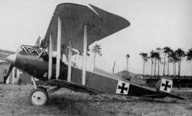
The Rumpler C III two seater was a development of the widely used C I with the one major difference that it lacked any form of fixed fin. In the event, this deletion was to be the design's downfall. Using a 220hp Benz Bz IV, the C III entered service in early 1917, but was withdrawn from operations within a month or so following a spate of crashes, attributed to the machine's lack of adequate latitudinal, or yawing control at low speed. It is reported that around 75 C IIIs had been delivered by Rumpler prior to the type's withdrawal from service.
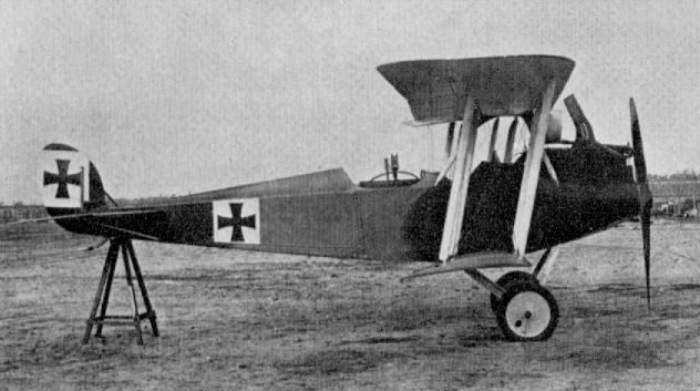
Rumpler C V
Rumpler C.IV
It was the intention of the Rumpler Werke to replace the C.Is with the neater and cleaner C.III type powered with the 220 h.p. Benz motor. However, this machine became no more than a development, for with the availability of considerably more powerful engines the next Rumpler aircraft to go into quantity production during 1917 was the C.IV, which had the 260 h.p. Mercedes installed.
Constructional technique did not differ much from that used in the C.I and C.Ia, yet the airframe presented a more refined appearance, possibly due to a certain elan imparted by the stagger and sweep of the wings. The Rumpler C.IV was received with enthusiasm by its crews; it had an excellent performance, and there were few Allied scouts that could catch it at altitudes exceeding 15,000 ft.
The engine installation was designed to give a clean nose-entry, and a large spinner was fitted to the airscrew. The first station of the fuselage was covered with a metal fairing, as were the nose panels, including the cylinder-block-fairings. Inevitably there were exceptions to the rule, and some C.IVs appeared without spinners, having simply a bulbous metal nose panel through which the propeller shaft protruded. Extending to a vertical knife edge at the rear, the fuselage was slab-sided, with a deeply curved decking forward of the cockpits and a shallower decking aft. Longerons were of ash forward of the cockpit area.. splicing into spruce in the rear half; spacers were of steel tube and ash in the fore and rear halves of the fuselage, respectively, and cables braced all bays. Covering was of fabric except for the ply decking between cockpits and engine, the side nose panels and the belly decking extending to the rear cockpit. A trap-door opening was made in the floor of the rear cockpit to facilitate photography.
Horizontal tail surfaces were of much improved pattern over the C.I types, although the vertical surfaces were little altered. On the C.IV the tailplane and divided elevators were of the curved "wing-nut" profile which became characteristic of the Rumplers. All tail surfaces were of steel tube with the exception of the tailplane ribs, which were of a reverse section to assist dive recovery. Light steel struts braced the fin to the tailplane, and similar struts braced the tailplane to the lower longerons, the struts raking forward from the hinge line to their attachment just below the leading edge.
The two-bay wing cellule was eminently graceful: it was also efficient. Without doubt it was the wing section and profile that made the major contribution to the Rumpler C.IV's excellent climb and altitude performance. All four wing panels were rigged with some 2 1/2 degrees of sweep, the top 2 panels being of parallel chord with angularly raked tips. Twin box spars (ash in the upper wing, spruce in lower) with steel-tube compression members and cable bracing formed the basis of the wing structure.
Ribs were built up of lightened plywood webs with softwood capping strips, and were interspaced with strip false ribs. Unbalanced ailerons of steel-tube framing and of inverse taper were hinged to a false spar at the upper wingtips and operated by a mid-span crank lever, from which the actuating cables ran vertically down and through the lower wing. The trailing edge was of flattened tube, to which the ends of the ribs were riveted. The lower wing was of unusual profile, being of "Libellen-Form" (dragonfly), which idea came from Mr. F. Budig, who was flying-research engineer in the Rumpler factory. Such was its efficiency that its shape was retained for all subsequent C types, as well as D and G.III types that were built.
The center-section cabane was a welded streamlined steel-tube trestle to which the upper wing panels were attached. It also supported the semicircular radiator, which, due to its now greater depth of section, was only partially recessed into the leading edge. Interplane struts were of plain steel tube encased in wooden fairings and braced with steel cables. A drag wire ran from the top of the front undercarriage strut to the top of the inboard front interplane strut, while another ran from the front former to the base of the front strut.
Rumpler C.IVs were mainly-used in strategic roles on long-range reconnaissance and photography missions, often probing deep behind the Allied lines and relying upon the high-altitude performance to elude hostile fighters.
Description: Two-seat reconnaissance and photographic duties.
Manufacturers: Rumpler Flugzeug-Werke G.m.b.H. Johannisthal (Ru.).
Sub-contractors: Bayerische Rumpler-Werke G.m.b.H. (Bayru.)
Pfalz Flugzeug-Werke G.m.b.H. (built as Pfalz C.I)
Power Plant: 260 h.p. Mercedes D.IVa 6 cylinder in-line water-cooled engine.
Dimensions:
Span 12.66 m. (41 ft. 6 1/2 in.)
Length 8.405 m. (27 ft. 7 in.)
Height 3.25 m. (10 ft. 8 in.)
Area 33.5 sq.m. (361-8 sq.ft.)
Weights:
Empty 1,080 kg. (2,376 lb.)
Loaded 1,530 kg. (3,366 lb.)
Performance:
Max. speed 106 m.p.h. at 1,640 ft.
Climb to
500 m. 2.00 min.
1,000 m. 3.75 min.
2,000 m. 8.4 min.
3,000 m. 14.25 min.
4,000 m. 21.75 min.
5,000 m. 38.00 min
Ceiling 21,000 ft.
Duration 3 1/2 - 4 hr.
Armament: One fixed Spandau machine-gun forward
and one manually operated Parabellum machine-gun in the rear cockpit.
Occasionally a light "nuisance value" bomb load of four 25 kg. (total 220 lb.) bombs
was carried on external racks on shorter-range sorties.
Rumpler Experimental C Type
This machine was a Rumpler C IV airframe experimentally fitted with a 350 h.p. Austro-Daimler vee-twelve engine. So far as is known, only the single example existed.
Pfalz C I
Although designated Pfalz C I, this 1917 machine was in reality a licence-built Rumpler C IV with small refinements added by the Pfalz Flugzeug-Werke. The main distinction of the Pfalz-built machine was the fitting of ailerons at all four wingtips and additional struts bracing the fin to the tailplane. Engine, 260 h.p. Mercedes D IVa. Span, 12.56 m. (41 ft. 2 1/2 in.). Length, 8.25 m. (27 ft. 0 3/4 in.). Height, 3.335 m. (10 ft. 11 5/8 in.). Area, 39.32 sq.m. (425 sq.ft.). Weights: Empty, 1,123 kg. (2,471 lb.). Loaded, 1,703 kg. (3,747 lb.). Speed, 175 km.hr. (109.375 m.p.h.). Climb, 1,000 m. (3,280 ft.) in 3 min., 5,000 m. (16,400 ft.) in 38 min. Duration, 3 1/2 hr. Armament, one Spandau and one Parabellum machine-guns.
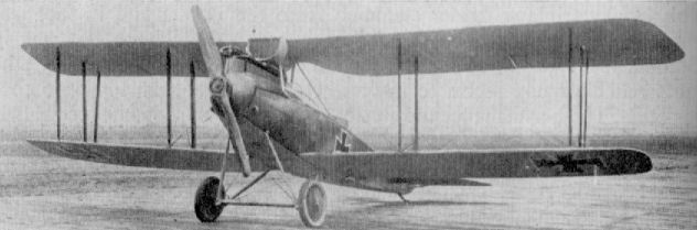
Pfalz C I
Rumpler C IX (7C 1) (first version)
This experimental two-seater appeared late in 1917. C IV wing panels were used with single 'T'-type interplane struts. The oval, multi-stringered fuselage had pleasing lines, but the pivoted, "all-moving" rudder was a particularly vulnerable component, and was subsequently modified. It was intended the type should be a two-seat fighter, but the machine could not have been successful, as it did not go into production. Engine, 160 h.p Mercedes D III.
Rumpler C IX (second version)
Although the trailing edge of the rudder is unfortunately clipped in this illustration, the general revision of the tail surfaces to include a fin may be seen.
Rumpler C VII and Rubild
Development of the highly successful Rumpler C IV resulted eventually in the appearance, in late 1917, of the C VII, with still further improved altitude performance. This aircraft was fitted with the "super compressed" (high-compression) 240 h.p. Maybach engine. Although the actual horsepower rating was lower than that of the 260 h.p. Mercedes, the power fall-off at extreme altitudes was much lower, and it was at such heights that the power ratio was seen to advantage. The intermediate C V was actually a development of the C III, and there appears to be no record of a C VI.
Two versions of the Rumpler C VII existed; the standard machine was used for long-distance reconnaissance and fitted with radio and normal armament of one fixed and one manually operated machine-gun. A special photo-reconnaissance version was known as the C VII (Rubild) and was fitted with specialised camera equipment for most advantageous use at peak altitudes. This model dispensed with the forward gun and ammunition, and all extraneous equipment was kept to a minimum. It was the Rumpler C VII (Rubild) that was the really high-flying Rumpler which often featured in Allied combat reports, and which proved almost impossible to intercept. Its ceiling was in the region of 24,000 ft., and even at 20,000 ft. a speed of 100 m.p.h. could be maintained a superb performance for the period.
In construction the C VII was almost identical to the C IV and differed only in detail. It was marginally smaller in overall dimensions than the CIV, but the only certain visual identification was by the exhaust manifold, which exhausted sideways to starboard and not upwards as on the earlier machine. The fuselage, as in the C IV, had a basic structure of timber with steel-tube spacers in the forward half of the fuselage. Nose-entry was not so sleek, as spinners were not fitted to C VIIs, simply a bulbous metal panel immediately behind the airscrew. Tail surfaces were of steel-tube framing and retained the earlier profile with the distinctive "wing-nut" profile horizontal surfaces. The reverse camber was still featured, and plain elevators were fitted instead of balanced as formerly.
Again the wings were as the C IV, but with a reduction of just over 4 1/4 in. in span, a slight increase in chord, however, gave a net increase in area of 1 sq.ft.! Unbalanced ailerons of steel-tube framing were fitted, and all interplane struts and centre-section cabane were interchangeable with those of the C IV. A slightly longer undercarriage chassis gave an increase in height of about 5 1/4 in., which permitted the fitting of airscrews of increased diameter.
Instances of the efficient performance of these Rumpler machines are cited in reports by Major J. B. McCudden, V.C., 15th December 1917:
"I dived on him from 19,800 feet for the Hun was at 19,000 feet. I closed on him and opened fire, but as I had mis-judged my speed and was overshooting, I had to turn to avoid running into him. I caught up with him again, but could not defeat him for the pilot was good and gave his gunner every opportunity, and I had to leave him very soon."
Again on 23rd December 1917:
"After 15 minutes I got up to his level at 18,200 feet over Peronne. He now saw me and climbed for a little while trying to outclimb me, but he could not for my machine was still going up well; but had we both been at 19,000 feet he could have done so for the Rumplers at 20,000 feet are extremely efficient with their heavily cambered wing, whereas the S.E. 5 at that height, although it is fast, has not much climb on account of its flat wing section. However I was now up at the Rumpler's height and he tried to run for it.
"I soon got into position but found he was every bit as fast as I was although I was able to keep up with him because he swerved to allow his gunner to fire at me and lost a certain amount of speed. I fought him down from 18,000 feet to 8,000 feet and he tried hard to save his life but after a final burst from both my machine-guns his right hand wings fell off and I very nearly flew into them."
As may be seen from the first combat, success did not always attend McCudden, and he again failed to get a Rumpler at 19,500 ft. on 3rd January 1918, reporting:
"I encountered a Rumpler over Bullecourt and fought him a long way east of his lines, but he was an old hand and saved his height instead of losing it and at last I had to leave him for we were now over Douai at 18,000 feet. Here I turned back, for a lucky shot from him might have disabled my engine and have caused me to come down."
The general immunity of the Rumplers to attack above 18,000 ft. is reflected in the comment by Major McCudden:
"I expect some of those Huns got a shock when they came over at 18,000 feet a n d were dived upon by an S.E. from above, for in winter it was an exception to the rule to see an S.E. above 17,000 feet, which was the ceiling of the average 200 h.p. S.E. with its war load. My machine had so many little things done to it that I could always go up t o 20,000 feet whenever I liked, and it was mainly the interest I took in my machine which enabled me to get up so high."
TECHNICAL DATA
Description: Long-range reconnaissance and photo-reconnaissance in Rubild model.
Manufacturer: Rumpler Flugzeug-Werke G.m.b.H. Johannisthal (Ru.).
Power Plant: One 240 h.p. Maybach Mb IV 6 cylinder in-line water-cooled engine.
Dimensions: Span, 12 55 m. (41 ft. 2 1/8 in.). Length, 8.2 m. (26 ft. 10 7/8 in.). Height, 3.39 m. (11 ft. 1 3/8 in.). Area, 33.6 sq.m. (363 sq.ft.).
Weights: Empty, 1,050 kg. (2,310 lb.). Loaded, 1,485 kg. (3,267 lb.).
Performance: Climb, 1,000 m. (3,280 ft.) in 2.3 min., speed 175 km.hr. (109.375 m.p.h.); 2,000 m. (6,560 ft.) in 4.3 min.; 3,000 m. (9,840 ft.) in. 8.0 min.; 4,000 m. (13,120 ft.) in 130 min.; 5,000 m. (16,400 ft.) in 21.5 min.; 6,000 m. (19,680 ft.) in 33.0 min, speed 160km.hr. (100 m.p.h.); 7,000 m. (22,960 ft.) in 50.0 min.; Service ceiling 23,944 ft. Duration, ca. 3 1/2 hr.
Armament: One fixed Spandau machine-gun forward and one manually operated Parabellum machine-gun in rear cockpit. C VII (Rubild) had no forward armament fitted.
Latest information (Feb. 1970) researched by Peter Grosz from Rumpler documents obtained from the late A. R. Weyl collection would indicate that the Rubild was, in fact, the C VI. There was no outward means of identification.

Rumpler C VII.
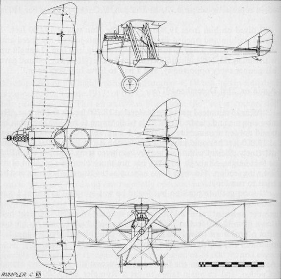
Rumpler C VIII
Although included in the C type category, the Rumpler C VIII had been developed with the intention of providing a good operational trainer for aircrews nearing the completion of their training. Previously, little equipment had been available other than the low-powered B type two-seaters and obsolete C types. The C VIII was provided to give training with emphasis on the observer's curriculum - including gunnery, observation, radio and photography - on an aircraft approaching more nearly operational standards, yet with ability to be operated economically, largely due to the installation of a 180 h.p. Argus engine.
Undoubtedly the spotlight fell upon the Jagdstaffeln, but it was the two-seater Fl. Abt. that did the donkey work in the German Air Force. With the approach of the final year of the war and the planned ultimate offensive on the Western Front for March 1918, it was hoped by the improvement and intensification of training of two-seater crews to achieve superior results, especially with more adequate protection from the Jastas and Schlachtsta formations. To facilitate this higher standard of training, the Rumpler C VIII came into use towards the end of 1917 with the F.E.A. (Flieger Ersatz Abteilungeri) "Flying Training Units".
The C VIII underwent its official Type Test at Johannisthal in November 1917, and some examples were also sold to the Dutch Government for use with their flying services.
In construction, the C VIII continued the style of its predecessors. Fuselage longerons were of ash forward, spliced into spruce in the rear half; spacers were of steel tube forward and spruce aft. The fore part of the fuselage was ply covered, except for the rounded nose panel of metal and the metal panels fairing the cylinder block; these now being much squarer than formerly. The rear part of the fuselage was fabric covered. Tail surfaces were all interchangeable with those of the C IV and C VII, with steel-tube framing and unbalanced control surfaces. The tailplane was of reversed camber section.
The wing surfaces reverted to the C I type in general shape, with both wings having angularly raked tips and being of parallel chord. The lower wing had long shallow cut-outs at the root to improve downward vision from the rear cockpit, while the upper wing had a narrow, rounded, centre-section cut-out. Conventional twin hollow box-spar construction was followed, with fretted ply ribs capped with softwood and false ribs spaced between the main ribs. Ailerons were unbalanced and of steel-tube framing. The upper wings were supported on a typical Rumpler trestle-type centre-section cabane, to which was also fixed the semicircular radiator. Both wings were swept at an angle of some 2 1/2°.
A streamlined steel-tube undercarriage chassis was fitted, and the wheels were sprung with spiral-steel springs. An orthodox steel-shod, ash tailskid was hinged to and internally sprung within the rear bay of the fuselage.
TECHNICAL DATA
Description: Two-seat operational trainer.
Manufacturer: Rumpler Flugzeug-Werke G.m.b.H., Johannisthal, Berlin (Ru.).
Engine: 180 h.p. Argus As III 6 cylinder in-line water-cooled engine.
Dimensions: Span, 12.18 m. (39 ft. 11 1/2 in.). Length, 8.02 m. (26 ft. 3 3/4 in.). Height, 3.2 m. (10 ft. 6 in.). Area, 36.2 sq.m. (391 sq.ft.).
Weights: Empty, 874 kg. (1,923 lb.) . Loaded, 1,374 kg. (3,023 lb.).
Performance: Maximum speed, 140 km. hr. (875 m.p.h.). Climb, 1,000 m . (3,280 ft.) in 4.25 min., 2,000 m. (6,560 ft.) in 11.0 min., 3,000 m. (9,840 ft.) in 21.0 min., 4,000 m. (13,120 ft.) in 37.5 min. Duration, ca. 4 hr.
Armament: One fixed Spandau machine-gun forward and one manually operated Parabellum machine-gun in the rear cockpit.
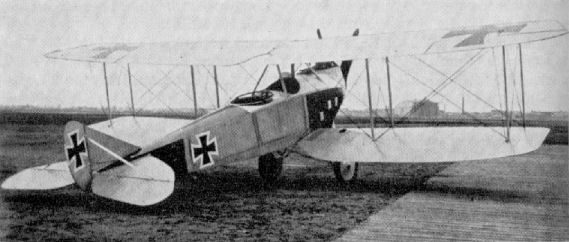
Rumpler C VIII.
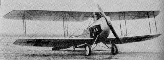
Rumpler C VIII.
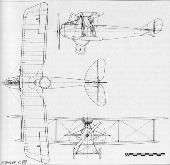
Rumpler 7D 1
This aircraft was the first of a series of experimental single-seat fighters which led eventually to the D I in 1918. The wooden, multi-stringered, streamlined fuselage was ply-skinned, then wrapped with doped fabric. The wings were orthodox, the upper wing being of parallel chord, the lower with a curved (dragonfly profile) trailing-edge. The engine was neatly cowled and combined with an extrusion of the fuselage to support the upper wing, which was not "gulled" as has been reported in the past. A flush radiator was mounted in the upper wing to port of the centre-line. Wide chord interplane struts of I-section braced the wing cellule. Engine, 160 h.p. Mercedes D III.
Rumpler 7D 2
Another prototype in the Rumpler D 1 evolution, the 7D 2 had the fuselage ply-skinned only fore and aft, the centre portion being simply fabric covered. It was also made deeper, and the lower wings built into it with smaller fairings. The upper wing, now with centrally mounted radiator, was supported on a more orthodox centre-section, found necessary to improve view from the cockpit. For this reason too the wide I-struts were replaced by more conventional twin struts. Engine, 160 h.p. Mercedes.
Rumpler 7D 4
Next development in this prototype series was the replacement of the twin interplane struts with single struts of "C" section in an endeavour to reduce drag. The radiators were now of the frontal "ear" type, placed low on the fuselage sides adjacent to the leading edge of the lower wings. They undoubtedly negatived any drag saving that had been effected by the revised wing-bracing system. Engine, 160 h.p. Mercedes. As far as can be ascertained, the 7D 5 did not differ visibly from the 7D 4.
Rumpler 7D 7
The Rumpler 7D 7, which followed a quadruplane project (7D 6), appeared to differ very little from the 7D 4, the only apparent variation being the encasement of the bracing cables in streamline casings. Engine fitted was now the more powerful 180 h.p. Mercedes D IIIa. Armament, twin Spandau machine-guns.
Rumpler D I (8D 1)
As may be seen, the eventual Rumpler D I did not differ markedly from its immediate prototypes. The introduction of balanced, overhung, ailerons may be noted; also the modification of the vertical tail surfaces to an exact triangular profile. The machine was said to have good flight characteristics except for sharp turns, when it too easily went into a spin. Two of these machines, 1552/18 and 1553/18, participated in the mid-summer D types Competition. Another, re-engined with the 185 h.p. B.M.W., took part in the third Competition in the autumn of 1918. Engine, 180 h.p. Mercedes IIIa. Span, 8.42 m. (27 ft. 7 1/2 in.). Length, 5.75 m. (18 ft. 10 3/8 in.). Height, 2.56 m. (8 ft. 4 3/4 in.). Area, 16 sq.m. (173 sq.ft.). Weights: Empty, 615 kg. (1,353 lb.). Loaded, 805 kg. (1,771 lb.). Speed, 180 km.hr. (112.5 m.p.h.) at 5,000 m. (16,400 ft.). Climb, 5,000 m. (16,400 ft.) in 26.5 min. and in 17.2 min. when fitted with high-compression engine. Duration, ca. 2 hr. Armament, twin Spandau machine-guns.
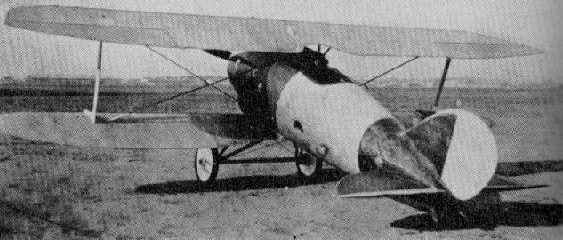
Rumpler 7D 7
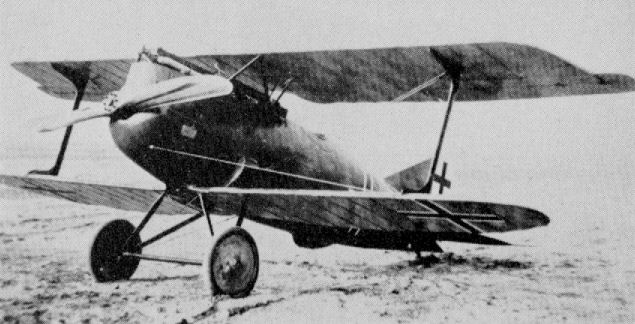
Rumpler D I (8D 1)
Rumpler C X (8C 14)
This progressive two-seater of 1918 featured the usual Rumpler wing profile, but with single bay "X" struts, which obviated the necessity for incidence bracing. Only a single aircraft was built, and when this was extensively damaged in a collision on the ground the type was not proceeded with. Engine, 240 h.p. Maybach Mb IV. Span, 10.5 m. (34 ft. 5 1/2 in.). Length, 6.9 m. (22 ft. 7 3/4 in.). Height, 3.12 m. (10 ft. 3 1/4 in.). Area, 29 sq.m. (313 sq.ft.). Weights: Empty, 950 kg. (2,090 lb.). Loaded, 1,385 kg. (3,047 lb.). Speed, 195 km.hr. (121.875 m.p.h.). Climb, 6,000 m. (19,680 ft.) in 27 min. Duration, 3 1/2 hr. Armament, one Spandau and one Parabellum machine-guns.
This progressive two-seater of 1918 featured the usual Rumpler wing profile, but with single bay "X" struts, which obviated the necessity for incidence bracing. Only a single aircraft was built, and when this was extensively damaged in a collision on the ground the type was not proceeded with. Engine, 240 h.p. Maybach Mb IV. Span, 10.5 m. (34 ft. 5 1/2 in.). Length, 6.9 m. (22 ft. 7 3/4 in.). Height, 3.12 m. (10 ft. 3 1/4 in.). Area, 29 sq.m. (313 sq.ft.). Weights: Empty, 950 kg. (2,090 lb.). Loaded, 1,385 kg. (3,047 lb.). Speed, 195 km.hr. (121.875 m.p.h.). Climb, 6,000 m. (19,680 ft.) in 27 min. Duration, 3 1/2 hr. Armament, one Spandau and one Parabellum machine-guns.
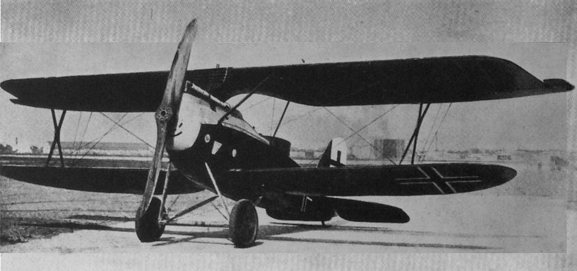
The Latest Rumpler C.X Type Two-seat Biplane. (240 h.p. Mercedes Mb IV.) Note the crossed interplane struts - a fashion now becoming prevalent in Germany. Prototype of 1918 only.
Sablatnig SF 1
Only a single example of this two-seat seaplane was built, and it was accepted by the Navy in October 1917. Engine, 160 h.p. Mercedes D III. Span, 191 m. (62 ft. 8 1/8 in.). Height, 4.35 m. (14 ft. 3 1/4 in.). Weights: Empty, 1,015 kg. (2,233 lb.). Loaded, 1,650 kg. (3,630 lb.). Speed, 125 km.hr. (78.125 m.p.h.). Climb, 1,000 m. (3,280 ft.) in 10 min. Armament, none.
Sablatnig SF 2
The Sablatnig SF 2 was a conventional wood and fabric seaplane used for reconnaissance and coastal patrol. A radio transmitter was carried, but no armament. Some twenty-six aircraft were delivered from August 1916 onwards, and were allocated Navy Numbers 580-585, 609-618, 705-714. Nos. 791-800 were built by L.V.G. (Koslin) and were probably SF 2s. Engine, 160 h.p. Mercedes D III. Span, 18.53 m. (60 ft. 9 5/8 in.). Length, 9.525 m. (31 ft. 3 in.). Height, 4.25 m. (13 ft. 11 1/4 in.). Area, 56 sq.m. (605 sq.ft.). Weights: Empty, 1,078 kg. (2,372 lb.). Loaded, 1,697 kg. (3,733 lb.). Speed, 130 km.hr. (81.25 m.p.h.). Climb, 1,500 m. (4,920 ft.) in 18 min. N.B. Data applies to aircraft 609, each batch often differing slightly from each other.
Sablatnig SF 5
A development of the earlier SF 2, the SF 5 was a conventional reconnaissance seaplane. Radio transmitter only was carried, and no armament. Altogether 101 aircraft of this type were delivered from March 1917 onwards, and it was only lack of sufficient data that prevented the type being dealt with in the main text. Navy Numbers allotted: 791-800 (L.F.G. built), 968-987, 1017-1036 (L.V.G. built), 1214-1223 (L.V.G. built), 1224-1233, 1352-1371, 1459-1468 (L.F.G. built), 1514. Engine, 150 h.p. Benz Bz III. Span, 17.3 m. (56 ft. 9 1/8 in.). Length, 9.6 m . (31 ft. 6 in.). Height, 3.55 m. (11 ft. 7 3/4 in.). Area, 50.5 sq.m. (545 sq.ft.). Weights: Empty, 1,052 kg. (2,314 lb.). Loaded, 1,605 kg. (3,531 lb.). Speed, 148 km.hr. (92.5 m.p.h.). Climb, 1,000 m. (3,280 ft.) in 11.6 min., 2,000 m. (6,560 ft.) in 21.8 min. N.B. Data applies to aircraft No. 1361, each batch often differing slightly from the other.
Sablatnig SF 6 (B I)
This machine was no more than an SF 5 fitted with an orthodox land undercarriage chassis and was intended for training duty. Only a single aircraft is thought to have been built. Engine, 150 h.p. Benz Bz III. Span, 17.3 m. (56 ft. 9 1/8 in.). Length, 8.3 m. (27 ft. 2 3/4 in.).
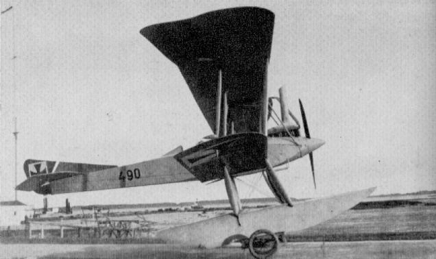
Sablatnig SF 1
Sablatnig C I
Built during 1917, the Sablatnig C I was a conventional C type two-seater of wood and fabric construction. At least two aircraft were built, Nos. 7700/17 (illustrated) and 7702/17, which served as prototypes for the subsequent N 1 type. The vee cut-outs in the trailing edge of the lower wings are usual - and unexplained. The lights built into the leading edge of the upper wing should be noted. Six 50 kg. bombs could be carried. Engine, 180 h.p. Argus As III. Span, 160 m. (52 ft. 6 in.). Length, 8.7 m. (28 ft. 6 1/2 in.). Weights: Empty, 1,050 kg. (2,310 lb.). Loaded, 1,540 kg. (3,380 lb.). Speed, 120 km.hr. (75 m.p.h.). Climb, 1,000 m. (3,280 ft.) in 9 min., 2,000 m. (6,560 ft.) in 20 min. Armament, one Parabellum machine-gun.
Sablatnig C II
Built round the 240 h.p. Maybach engine during 1918, the Sablatnig C II remained only an experimental prototype. The wings were braced with two bays of I-struts, and the fuselage and vertical fin were ply-covered. In many respects the machine favoured the SF 7 seaplane, the inboard wing bay being braced in identical manner. Engine, 240 h.p. Maybach Mb IV. Span, 12.5 m. (41 ft. 0 1/4 in.). Length, 8.3 m. (27 ft. 2 3/4 in.). Height, 3.2 m. (10 ft. 6 in.). Weights: Empty, 1,070 kg. (2,354 lb.). Loaded, 1,600 kg. (3,520 lb.). Speed, 150 km.hr. (93.75 m.p.h.). Climb, 1,000 m. (3,280 ft.) in 4.5 min., 5,000 m. (16,400 ft.) in 30 min. Range, 525 km. (328 miles). Armament, one Parabellum and one Spandau machine-guns.
Sablatnig Experimental C Type
These two machines were variants of the C II machine in an obvious endeavour to compare the advantages of the more normal parallel strut arrangement (above) with the I-strut system of the C II. For further comparison the X-strut cellule (below) was tried, this machine also differing in having overhung balanced elevators. Although not confirmed, dimensions were doubtless largely the same as those for the C II. Engine, 245 h.p. Maybach Mb IV.
Sablatnig N I
Built during 1918 to the N specification (which was first devised in August 1917), calling for a single-engined two-seat night bomber, the Sablatnig N I bore more than a passing resemblance to the C I. Probably a short series was constructed, as Serial Nos. 7729/17 and 7730/17 have been noted in addition to 7745/17 (illustrated above). Engine, 220 h.p. Benz Bz IV. Span, 16.0 m. (52 ft. 6 in.). Length, 8.7 m. (28 ft. 6 1/2 in.). Height, 3.2 m. (10 ft. 6 in.). Weights: Empty, 1,190 kg. (2,618 lb.). Loaded, 1,860 kg. (4,092 lb.). Speed, 125 km.hr. (78.125 m.p.h.). Climb, 1,000 m. (3,280 ft.) in 10 min., 4,000 m. (13,120 ft.) in 59 min. Armament, one Parabellum and one Spandau machine-guns.
Sablatnig SF 3
Designed as a two-seat seaplane fighter for escort and offensive patrols, only the single aircraft (No. 619) was built. It was a neat-looking machine with ply-covered fuselage. Engine, 220 h.p. Benz Bz IV. No other data available.
Sablatnig SF 7
Developed from the SF 3, again as a two-seat fighter seaplane, the SF 7 was fitted with the powerful 240 h.p. Maybach motor. Three aircraft were built, Nos. 1475-1477, and accepted by the Navy in September 1917. The I-type interplane struts are noteworthy, also the inboard wire-less bay braced by rigid diagonal struts from the top longerons. Engine, 240 h.p. Maybach Mb IV. Weight: Loaded, 2,120kg. (4,664 lb.). Speed, 162 km.hr. (101.25 m.p.h.). Climb, 1,000 m. (3,280 ft.) in 8 min., 3,000 m. (9,840 ft.) in 36 min. Armament, one Spandau and one Parabellum machine-guns.
Sablatnig SF 4
Ordered on 17th July 1916, the SF 4 was not delivered until 17th February 1917. Only the single example of this single-seat seaplane station defence fighter was built. No. 900. A triplane version was also constructed, No. 901. Engine, 150 h.p. Benz III. Span, 120 m. (39 ft. 4 1/2 in.). Length, 8.33 m. (27 ft. 4 in.). Height, 3.73 m. (12 ft. 2 7/8 in.). Area, 28.26 sq.m. (300 sq.ft.). Weights: Empty, 798 kg. (1,756 lb.). Loaded, 1,078 kg. (2,372 lb.). Speed, 158 km.hr. (98.75 m.p.h.). Climb, 1,000 m. (3,280 ft.) in 5.5 min., 2,000 m. (6,560 ft.) in 14 min. Armament, one Spandau machine-gun forward. N.B. The triplane variant spanned 9.25 m. (30 ft. 4 1/8 in.) and was 28.38 sq.m. (306 sq.ft.) in area.
Ordered on 17th July 1916, the SF 4 was not delivered until 17th February 1917. Only the single example of this single-seat seaplane station defence fighter was built. No. 900. A triplane version was also constructed, No. 901. Engine, 150 h.p. Benz III. Span, 120 m. (39 ft. 4 1/2 in.). Length, 8.33 m. (27 ft. 4 in.). Height, 3.73 m. (12 ft. 2 7/8 in.). Area, 28.26 sq.m. (300 sq.ft.). Weights: Empty, 798 kg. (1,756 lb.). Loaded, 1,078 kg. (2,372 lb.). Speed, 158 km.hr. (98.75 m.p.h.). Climb, 1,000 m. (3,280 ft.) in 5.5 min., 2,000 m. (6,560 ft.) in 14 min. Armament, one Spandau machine-gun forward. N.B. The triplane variant spanned 9.25 m. (30 ft. 4 1/8 in.) and was 28.38 sq.m. (306 sq.ft.) in area.
Sablatnig C III
Although no data on this interesting machine is available, it appears to have been based on the same ply-covered fuselage and tail surfaces as the C II. The low wing was of parallel chord and fitted with overhung, balanced ailerons. It was cable braced to the top of the fuselage, and underneath the cables were anchored to an additional pylon incorporated in the undercarriage chassis. A large lifting surface, as in the Fokker D VII, faired in the axle and spreaders. Engine, 245 h.p. Maybach Mb IV (probably).
Although no data on this interesting machine is available, it appears to have been based on the same ply-covered fuselage and tail surfaces as the C II. The low wing was of parallel chord and fitted with overhung, balanced ailerons. It was cable braced to the top of the fuselage, and underneath the cables were anchored to an additional pylon incorporated in the undercarriage chassis. A large lifting surface, as in the Fokker D VII, faired in the axle and spreaders. Engine, 245 h.p. Maybach Mb IV (probably).
Sablatnig SF 8
Designed purely as a dual-control school seaplane, the first SF 8 was delivered on 17th January 1918. A total of forty-one aircraft was ordered, Nos. 2020-2022 and 6001-6038, but it is not certain that all were delivered. Engine, 150 h.p. Benz Bz III. Span, 160 m. (52 ft. 6 in.). Length, 10.2 m. (33 ft. 5 5/8 in.). Height, 3.8 m. (12 ft. 5 5/8 in.). Area, 54.6 sq.m. (590 sq.ft.). Weights: Empty, 1,183 kg. (2,603 lb.). Loaded, 1,574 kg. (3,465 lb.). Speed, 130 km.hr. (81.25 m.p.h.). Climb, 1,000 m. (3,280 ft.) in 14.7 min., 2,000 m. (6,560 ft.) in 24.8 min. N.B. Data applies to aircraft "2021".
Designed purely as a dual-control school seaplane, the first SF 8 was delivered on 17th January 1918. A total of forty-one aircraft was ordered, Nos. 2020-2022 and 6001-6038, but it is not certain that all were delivered. Engine, 150 h.p. Benz Bz III. Span, 160 m. (52 ft. 6 in.). Length, 10.2 m. (33 ft. 5 5/8 in.). Height, 3.8 m. (12 ft. 5 5/8 in.). Area, 54.6 sq.m. (590 sq.ft.). Weights: Empty, 1,183 kg. (2,603 lb.). Loaded, 1,574 kg. (3,465 lb.). Speed, 130 km.hr. (81.25 m.p.h.). Climb, 1,000 m. (3,280 ft.) in 14.7 min., 2,000 m. (6,560 ft.) in 24.8 min. N.B. Data applies to aircraft "2021".
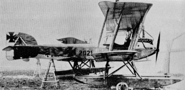
Sablatnig SF 8
Schneider Fighter
Flugmaschine Fabrik Franz Schneider G.m.b.H. was founded by Franz Schneider in 1917 for repair and servicing of Albatros. D.F.W. and L.V.G. aircraft. Before the war Schneider had been associated with the French manufacturer Edouard Nieuport, and later was responsible for some of the best L.V.G. designs. In 1918 he produced the single-seater illustrated here. No details are available, but its resemblance to the Nieuports is unmistakable. The placing of the ailerons at the lower wingtips was unusual. Engine, 200 h.p. Goebel Goe III. Armament, twin Spandau machine-guns.
Flugmaschine Fabrik Franz Schneider G.m.b.H. was founded by Franz Schneider in 1917 for repair and servicing of Albatros. D.F.W. and L.V.G. aircraft. Before the war Schneider had been associated with the French manufacturer Edouard Nieuport, and later was responsible for some of the best L.V.G. designs. In 1918 he produced the single-seater illustrated here. No details are available, but its resemblance to the Nieuports is unmistakable. The placing of the ailerons at the lower wingtips was unusual. Engine, 200 h.p. Goebel Goe III. Armament, twin Spandau machine-guns.
Schutte-Lanz C I
Originally founded in 1909 for the manufacture of dirigible airships, Luftfahrzeugbau Schutte-Lanz also undertook the construction of aircraft during the war. Ago and L.V.G. two-seaters were built in some numbers under licence, as were a few Staaken Giants. None of the firm's own designs progressed beyond the prototype stage. First original design was this pusher, twin-boom (Gitterschwanz) two-seater C I of 1915. With the nacelle mounted direct to the upper wing, the gunner in the nose cockpit was afforded a good all-round field of fire. Only the single machine was built. Engine, 160 h.p. Mercedes D III. Armament, one Parabellum machine-gun.
Originally founded in 1909 for the manufacture of dirigible airships, Luftfahrzeugbau Schutte-Lanz also undertook the construction of aircraft during the war. Ago and L.V.G. two-seaters were built in some numbers under licence, as were a few Staaken Giants. None of the firm's own designs progressed beyond the prototype stage. First original design was this pusher, twin-boom (Gitterschwanz) two-seater C I of 1915. With the nacelle mounted direct to the upper wing, the gunner in the nose cockpit was afforded a good all-round field of fire. Only the single machine was built. Engine, 160 h.p. Mercedes D III. Armament, one Parabellum machine-gun.
Schutte-Lanz D I
This type appeared in 1915, and apart from the absence of vertical fin and modified undercarriage chassis - note the unusual forward rake - the type appears to have been copied from the Sopwith Tabloid. Engine, 100 h.p. Gnome. Span, 7.5 m. (24 ft. 7 3/8 in.). Length, 5.4 m. (18 ft. 8 5/8 in.).
This type appeared in 1915, and apart from the absence of vertical fin and modified undercarriage chassis - note the unusual forward rake - the type appears to have been copied from the Sopwith Tabloid. Engine, 100 h.p. Gnome. Span, 7.5 m. (24 ft. 7 3/8 in.). Length, 5.4 m. (18 ft. 8 5/8 in.).
Schutte-Lanz G I
This experimental twin-engined machine was to the original K (Kampfflugzeug) specification for large fighting aircraft, but the designation was later changed to "G" for twin-engined machines. This aircraft had a slab sheet-covered fuselage of quintagonal section, the top being flat, the sides tapered in "tumblehome" fashion and the two bottom surfaces met at an angle at the centre-line. The engines were mounted well forward on the lower wings, with the pusher airscrews driven through extended shafts to clear the trailing edge. The triangular tailplane extended almost half the length of the fuselage, and by comparison the comma rudder seemed ridiculously small. Engines, 2 X 160 h.p. Mercedes D III. Span, 22 m. (72 ft. 2 1/4 in.). Length, 12 m. (39 ft. 4 1/2 in.). Height, 4.2 m. (13 ft. 9 3/8 in.). Area, 100 sq.m. (1,080 sq.ft.). Weights: Empty, 1,850 kg. (4,070 lb.). Loaded, 3,100 kg. (6,820 lb.). Speed, 125 km.hr. (78.125 m.p.h.). Duration, 6 hr. Armament, one Parabellum machine-gun in nose.
This experimental twin-engined machine was to the original K (Kampfflugzeug) specification for large fighting aircraft, but the designation was later changed to "G" for twin-engined machines. This aircraft had a slab sheet-covered fuselage of quintagonal section, the top being flat, the sides tapered in "tumblehome" fashion and the two bottom surfaces met at an angle at the centre-line. The engines were mounted well forward on the lower wings, with the pusher airscrews driven through extended shafts to clear the trailing edge. The triangular tailplane extended almost half the length of the fuselage, and by comparison the comma rudder seemed ridiculously small. Engines, 2 X 160 h.p. Mercedes D III. Span, 22 m. (72 ft. 2 1/4 in.). Length, 12 m. (39 ft. 4 1/2 in.). Height, 4.2 m. (13 ft. 9 3/8 in.). Area, 100 sq.m. (1,080 sq.ft.). Weights: Empty, 1,850 kg. (4,070 lb.). Loaded, 3,100 kg. (6,820 lb.). Speed, 125 km.hr. (78.125 m.p.h.). Duration, 6 hr. Armament, one Parabellum machine-gun in nose.
Schutte-Lanz D III
Built towards the end of 1917, this neat but conventional fighter participated in the first D types Competition at Adlershof. It was flown by von Arnim, and at a loaded weight of 900 kg (1,980 lb.) on 25th January 1918 recorded climb performance of 1,000 m. (3,280 ft.) in 3 min. and 5,000 m. (16,400 ft.) in 31.9 min., which, as may be seen, was far from spectacular. An unusual feature was the use of fairly long, downturned, individual exhaust pipes to each cylinder. The machine was of orthodox wood and fabric construction. Dihedral was rigged in the upper wing but not in the lower wing. Engine, 160 h.p. Mercedes D III. Armament, twin Spandau machine-guns.
Built towards the end of 1917, this neat but conventional fighter participated in the first D types Competition at Adlershof. It was flown by von Arnim, and at a loaded weight of 900 kg (1,980 lb.) on 25th January 1918 recorded climb performance of 1,000 m. (3,280 ft.) in 3 min. and 5,000 m. (16,400 ft.) in 31.9 min., which, as may be seen, was far from spectacular. An unusual feature was the use of fairly long, downturned, individual exhaust pipes to each cylinder. The machine was of orthodox wood and fabric construction. Dihedral was rigged in the upper wing but not in the lower wing. Engine, 160 h.p. Mercedes D III. Armament, twin Spandau machine-guns.
Schutte-Lanz D IV
Unfinished airframe of D IV shows ply-covered fuselage. It has not been established if the aircraft was ever completed.
Schutte-Lanz D VII
Completed during 1918, the D VII was the last of the Schutte-Lanz fighters. A development of the D III, the wing cellule was largely the same, with the same dihedral arrangement. Ailerons were now additionally fitted to the lower wingtips to improve lateral control. The radiator was a car-type component fitted on the extreme nose of the plywood-covered fuselage. This machine competed in the mid-summer D types Competition and, piloted by Nestler, at a loaded weight of 926.3 kg. (2,038 lb.) it climbed 1,000 m. (3,280 ft.) in 3.1 min. and 5,000 m. (16,400 ft.) in 34.8 min. Engine, 180h.p. Mercedes D IIIa. Armament, twin Spandau machine-guns.
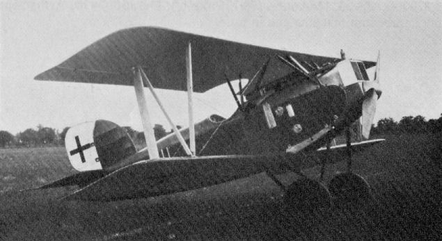
Schutte-Lanz D.VII (1918)
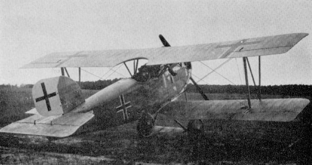
Schutte-Lanz D VII
Schutte-Lanz Dr I
This machine was simply a triplane version of the D III. Engine, 160 h.p. Mercedes D III.
This machine was simply a triplane version of the D III. Engine, 160 h.p. Mercedes D III.
Schutte-Lanz D VI
After the projected D V, which was not built, the next Schutte-Lanz original production was the D VI, an interesting parasol monoplane. The parallel struts which braced the wings were covered for most of their length with an airfoil section fairing to form an additional lifting surface. Unfortunately the aircraft crashed on its first flight on 29th May 1918 and was not rebuilt. Engine, 160 h.p. Mercedes D III.
After the projected D V, which was not built, the next Schutte-Lanz original production was the D VI, an interesting parasol monoplane. The parallel struts which braced the wings were covered for most of their length with an airfoil section fairing to form an additional lifting surface. Unfortunately the aircraft crashed on its first flight on 29th May 1918 and was not rebuilt. Engine, 160 h.p. Mercedes D III.
Schwade Single-seater
The two aircraft illustrated are the only known wartime products of the Schwade Flugzeug und Motorenbau of Erfurt. Unfortunately no data is available, although it is obvious they were extremely diminutive machines with a span roughly between 6 and 7 m. (19 ft. 8 1/4 in. to 22 ft. 11 5/8 in.). The earlier machine had tubular outriggers supporting the tail, and the second machine what appears to be ply-covered booms. A single-seat triplane was also built, but no photograph has been traced. Engine, 80 h.p. Oberursel (1914 machine), 110 h.p. Oberursel (1916 machine).
The two aircraft illustrated are the only known wartime products of the Schwade Flugzeug und Motorenbau of Erfurt. Unfortunately no data is available, although it is obvious they were extremely diminutive machines with a span roughly between 6 and 7 m. (19 ft. 8 1/4 in. to 22 ft. 11 5/8 in.). The earlier machine had tubular outriggers supporting the tail, and the second machine what appears to be ply-covered booms. A single-seat triplane was also built, but no photograph has been traced. Engine, 80 h.p. Oberursel (1914 machine), 110 h.p. Oberursel (1916 machine).
Siemens-Schuckert "Bulldog"
Based on a pre-war design that had been constructed for Prince Friedrich Sigismund of Prussia, these two "Bulldog" monoplanes differed only in engine installation. They were completed early in 1915, but were declined by the authorities owing to their poor performance and handling qualities. Engine, 100 h.p. Siemens-Halske Sh I, 100 h.p. Mercedes D I.
Based on a pre-war design that had been constructed for Prince Friedrich Sigismund of Prussia, these two "Bulldog" monoplanes differed only in engine installation. They were completed early in 1915, but were declined by the authorities owing to their poor performance and handling qualities. Engine, 100 h.p. Siemens-Halske Sh I, 100 h.p. Mercedes D I.
Siemens-Schuckert B
This two-seat machine was designed by Steffen and built during 1915 for unarmed tactical reconnaissance. A novel feature in construction was the use of tubular steel wing spars. The aircraft was delivered to the Brieftauben Abteilungen at Ostend at the express request of the Commanding Officer, where it crashed. Usable parts were shipped back to the S.S.W. factory and subsequently used in construction of the E II. Engine, 100 h.p. Siemens-Halske Sh I. Span, 12.4 m. (40 ft. 8 1/4 in.). Length, 6.2 m. (20 ft. 4 3/8 in.). Speed achieved on test, 153 km.hr. (95.625 m.p.h.).
This two-seat machine was designed by Steffen and built during 1915 for unarmed tactical reconnaissance. A novel feature in construction was the use of tubular steel wing spars. The aircraft was delivered to the Brieftauben Abteilungen at Ostend at the express request of the Commanding Officer, where it crashed. Usable parts were shipped back to the S.S.W. factory and subsequently used in construction of the E II. Engine, 100 h.p. Siemens-Halske Sh I. Span, 12.4 m. (40 ft. 8 1/4 in.). Length, 6.2 m. (20 ft. 4 3/8 in.). Speed achieved on test, 153 km.hr. (95.625 m.p.h.).

Siemens-Schuckert B (1915)
Siemens-Schuckert D D5
This single-seat biplane, of which only a single example was built, bore a strong resemblance to the earlier Type B. It was built in 1916 and featured tapered wings with steel tube spars and a ply-covered fuselage similar to the E I-III. It was presented to Idflieg for acceptance trials, during which it was rejected on grounds of poor aerodynamic qualities and restricted visibility from the cockpit. Engine, 110 h.p. Siemens-Halske Sh I. Armament, one Spandau machine-gun.
This single-seat biplane, of which only a single example was built, bore a strong resemblance to the earlier Type B. It was built in 1916 and featured tapered wings with steel tube spars and a ply-covered fuselage similar to the E I-III. It was presented to Idflieg for acceptance trials, during which it was rejected on grounds of poor aerodynamic qualities and restricted visibility from the cockpit. Engine, 110 h.p. Siemens-Halske Sh I. Armament, one Spandau machine-gun.
Siemens-Schuckert E I
Following its appearance in the autumn of 1915, a small batch of twenty of these aircraft was ordered. The prototype is illustrated. It was of conventional construction, with ply-covered fuselage and fabric-covered wings, with warp control instead of ailerons; production machines did not feature the pointed spinner of the prototype. Engine, 100 h.p. Siemens-Halske Sh I. Span, 100 m. (32 ft. 9 3/4 in.). Length, 7.1 m. (23 ft. 3 5/8 in.). Weights: Empty, 473 kg. (1,041 lb.). Loaded, 673 kg. (1,481 lb.). Duration, 1 1/2 hr. Armament, one Spandau machine-gun.
The Siemens-Schuckert E III. built in 1916, was virtually an E I with a 100 h.p. Oberursel U I engine. One Spandau gun was fitted. Only six machines were built.
Siemens-Schuckert E II
Only a single E II was built, similar in most respects to the E I, but with an in-line engine instead of a rotary. The machine was completed early in 1916, but destroyed in June of that year when being demonstrated at Doberitz by Franz Steffen, who was killed in the crash. Engine, 120 h.p. Argus As II. Armament, one Spandau machine-gun.
Siemens Forssman (first version)
Designed by Forssman, this four-engined machine was obviously influenced by Russian Sikorsky bombers. Construction commenced in October 1914, and completion was in spring of 1915, but although a speed of 115 km.hr. (71.8 m.p.h.) was attained on test, the aircraft was generally under-powered and modifications were put in hand. In its very first appearance the aircraft had no nose turret; this was added later to give better weight distribution. Engines, four 110 h.p. Mercedes. Span, 24 m. (78 ft. 9 in.). Length, 16.5 m. (54 ft. 1 3/4 in.). Area, 140 sq.m. (1,512 sq.ft.). Weights: Empty, 3,250 kg. (7,150 lb.). Speed, 115 km.hr. (71.825 m.p.h.).
Siemens Forssman (final version)
After extensive modification, this version first flew in September 1915. The nose had been converted to an enclosed, streamlined cabin, the inner engines were now eight-cylinder 220 h.p. Mercedes D lVs, and the outer engines were suspended between the wings. The machine was finally accepted by Idflieg (Inspectorate of Flying Troops) in April 1916 for training purposes only. Further development was discontinued, as the type was by then obsolescent. Engines, two 110 h.p. Mercedes, 2 x 220 h.p. Mercedes. Span, 24 m. (78 ft. 9 in.). Length, 16.5 m. (54 ft. 1 3/4 in.). Area, 140 sq.m. (1,512 sq.ft.). Weights: Empty, 4,000 kg. (8,800 lb.). Loaded, 5,200 kg. (11,400 lb.). Speed, 120 km.hr. (75 m.p.h.). Climb, 2,000 m. (6,560 ft.) in 29 min.
Siemens-Schuckert Steffen R I
In December 1914 Siemens-Schuckert began construction of a series of seven "fork-tail" three-engined Giants designed by Bruno and Franz Steffen. All machines were generally similar, differing mainly in engine installation and wing span, as reference to data below will show. The fork-tail feature was to allow a clear field of fire to the rear. All three engines were mounted inside the nose, with facilities for minor repairs during flight; power was transmitted to two tractor airscrews through a series of shafts and gears.
R I. Serial R 1/15. Engines, three 150 h.p. Benz Bz III. Span. 28 m. (91 ft. 10 1/2 in.). Length, 17.5 m. (57 ft. 5 1/8 in.). Height, 5.2 m. (17 ft. 3/4 in.). Area, 138 sq.m. (1,490 sq.ft.). Weights: Empty, 4,000 kg (8,800 lb.). Loaded, 5,200 kg. (11,440 lb.). Speed, 110 km.hr. (68.75 m.p.h.). Climb, 2,000 m. (6,560 ft.) in 35 min. Duration, 4 hr. Notes: First flew May 1915, accepted July 1915. Tried at the Front, but not operational. Trainer only.
<...>
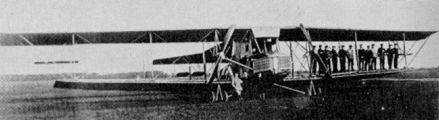
Siemens-Schuckert Steffen R I
Siemens-Schuckert Steffen R I
In December 1914 Siemens-Schuckert began construction of a series of seven "fork-tail" three-engined Giants designed by Bruno and Franz Steffen. All machines were generally similar, differing mainly in engine installation and wing span, as reference to data below will show. The fork-tail feature was to allow a clear field of fire to the rear. All three engines were mounted inside the nose, with facilities for minor repairs during flight; power was transmitted to two tractor airscrews through a series of shafts and gears.
<...>
R II. Serial R 2/15. Engines, three 260 h.p. Mercedes D IVa. Span, 38 m. (124 ft. 8 1/4 in.). Length, 18.5 m. (60 ft. 84, in.). Height, 4.6 m. (15 ft. 1 1/8 in.). Area, 233 sq.m. (2,516 sq.ft.). Weights: Empty, 6.150 kg. (13,530 lb.). Loaded, 8,460 kg. (18,612 lb.). Speed, 110 km.hr. (68.75 m.p.h.). Climb, 2,000 m. (6,560 ft.) in 23 min. Duration, 4 hr. Notes: First flew end of 1915, when original Maybach engines had been replaced by Mercedes. Span increased. Accepted 26th June 1917. Trainer only.
R III. Serial R 3/15. Engines, three 220 h.p. Benz Bz IV. Span, 34.33 m. (112 ft. 7 3/4 in.). Length, 17.7 m. (58 ft. 0 7/8 in.). Height, 4.6 m. (15 ft. 8 1/8 in.). Area, 177 sq.m. (1,912 sq.ft.). Weights: Empty, 5,400 kg (11,880 lb.). Loaded, 6,820 kg. (15,004 lb.). Speed, 132 km.hr. (82.5 m.p.h.). Climb, 2,000 m. (6,560 ft.) in 35 min. Duration, 4 hr. Notes: Benz engines substituted for original Maybachs. Span decreased. Accepted December 1916. Training duties only.
R IV. Serial R 4/15. Engines, three 220 h.p. Benz Bz IV. Span, 37.6 m. (123 ft. 4 1/2 in.). Length, 18 m. (59 ft. 0 3/4 in.). Height, 4.6 m. (15 ft. 1 1/8 in.). Area, 201 sq.m. (2,171 sq.ft.). Weights: Empty, 5,450 kg. (11,990 lb.). Loaded, 6,900 kg. (15,180 lb.). Speed, 130 km.hr. (81.25 m.p.h.). Climb, 2,000 m. (6,560 ft.) in 36 min. Duration, 4 - 5 hr. Armament, four machineguns. Notes: Benz engines substituted for original Maybachs. Span increased. Crew, four. Accepted August 1916. Operational with Rfa 501 at Vilna on Russian Front. Used for radiator experiments.
R V. Serial R 5/15. Engines, three 220 h.p. Benz Bz. IV. Span, 34.33 m. (112 ft. 7 3/4 in.). Length, 17.7 m. (58 ft. 0 7/8 in.). Height, 4.6 m. (15 ft. 1 1/8 in.). Area, 177 sq.m. (1,912 sq.ft.). Weights: Empty, 5,300 kg. (11,600 lb.). Loaded, 6,766 kg. (14,885 lb.). Speed, 132 km.hr. (82.5 m.p.h.). Climb, 2,000 m. (6,560 ft.) in 36 min. Duration, 4 hr. Armament, four machineguns. Notes: Benz engines substituted for original Maybachs. Decreased span. Accepted August 1916. Crew,six. Operational with Rfa 501 at Vilna.
R VI. Serial R6/15. Engines, three 220h.p. Benz Bz IV. Span, 33.36m. (109 ft. 5 5/8 in.). Length, 17.7 m. (58 ft. 0 5/8 in.). Height, 4.6 m. (15 ft. 1 1/8 in.). Area, 171 sq.m. (1,847 sq.ft.). Weights: Empty, 5,250 kg. (11.550 lb.). Loaded, 6,800 kg. (14,960 lb.). Speed, 132 km.hr. (82.5 m.p.h.). Climb, 2,000 m. (6,560 ft.) in 36 min. Duration, 4 - 6 hr. Armament, four machineguns. Notes: Benz engines substituted for original Maybachs. Decreased span. Crew six. Operational with Rfa 501 at Vilna.
R VII. Serial R7/15. Engines, three 260 h.p. Mercedes D IVa. Span, 38.44 m. (126 ft. 1 1/2 in.). Length, 18.5 m. (60 ft. 8 1/2 in.). Height, 4.6 m. (15 ft. 1 1/8 in.). Area, 210 sq.m. (2,268 sq.ft.). Weights: Empty, 5,700 kg. (12,540 lb.). Loaded, 7,960 kg. (17,512 lb.). Speed, 130 km.hr. (81.25 m.p.h.). Climb, 2,000 m. (6,560 ft.) in 27 min. Duration, 4 hr. Armament, four machine-guns. Notes: Benz engines substituted for original Maybachs. New wings and rib section of increased span. Crew six. Accepted February 1917. Operational with Rfa 501 at Vilna.
Siemens-Schuckert D I
Siemens-Halske O.H. was founded in 1847 to manufacture telegraphic equipment. It was not until 1873 that the more famous Siemens-Schuckert Werke title was adopted on the merging with the Schuckert works of Nurnberg to form the giant electrical combine.
The firm made a tentative excursion into the aircraft manufacturing field in 1907, when a non-rigid military airship was constructed at the request of the German General Staff. From 1909 to 1911 three original aircraft were built, the last bearing a close resemblance to the Bleriot monoplanes. Interest in aircraft manufacture then ceased until 1914, when, in response to urgent requests for aeroplanes from the German military forces, the aircraft department was reopened on a new footing under the direction of Dr. Walter Reichel, assisted by Dr. Hugo Natalis, Wolff, the Steffen brothers (Franz and Bruno) and Forssman.
Initially "Giant" R (Riesenflugzeug) aircraft were designed and built, apart from the "Bulldog" monoplane, but towards the end of 1915 appeared the S.S.W. E 1, a neat shoulder-wing monoplane. It was accepted by Idflieg (Inspectorate of Flying Troops), and a small batch was built to bolster supplies of Fokker and Pfalz monoplanes. At this time the first French Nieuport scouts were enjoying a considerable success on the Western Front, and as there was no immediate prospect of Germany having a superior machine forthcoming, Idflieg requested the Albatros, Euler and S.S.W. firms to produce quickly an improved copy of the Nieuport as a means of obtaining parity with their opponents. Captured Nieuports were supplied to the firms as models, but Albatros did not make such a close copy of the French machine as did Siemens-Schuckert. Their machine closely resembled the Nieuports XI and XVII, differing noticeably only in the engine installation and, later, the tailskid arrangement. In October 1916 Bruno Steffen climbed to an altitude of 5,000 m. in 45 min. on the prototype Siemens-Schuckert D.I.
The D.I was accepted for production, and on 25th November 1916 an initial order for 150 machines was placed. Production was somewhat tardy, airframes being held up for their engines-which were by way of being something new in geared rotaries-and a later order (21st March 1917) for 100 machines was cancelled, as it was found that by mid 1917 performance of the S.S.W. D.I was no longer up to requirements. Eventually only 95 aircraft of the original order were completed; 22 by the Berlin factory and 73 at Nurnberg. A further 55 uncovered airframes were delivered to Adlershof.
Power unit of the D.I was the Siemens-Halske Sh.I geared rotary, which had been developed by yet another branch of the Siemens combine. This was an engine of considerable mechanical ingenuity, in which the crankcase rotated in one direction at about 900 r.p.m. and the crankshaft in the opposite direction at the same speed, thereby achieving a virtual engine speed of 1,800 r.p.m. for an airscrew speed of only 900 r.p.m. This resulted in greater propeller efficiency. The engine was mounted in an open-fronted horse-shoe-type cowling, which incorporated a front bearer spider and was cut away almost completely in the lower half to allow free escape of exhaust. The fuselage, based on four main longerons, was a slab-sided braced box-girder. The top decking was rounded both fore and aft of the cockpit, with light formers and stringers. With the lower longerons being set closer together than the upper pair, the sides tapered in, exactly as in the Nieuport model The foremost bay of the fuselage sides was covered with slightly bulged metal panels, which were embossed with large vertical ventilation louvers, the remainder was fabric covered.
Tail surfaces were all of steel-tube framing and fabric covered, the trapezoidal tailplane and unbalanced elevators being mounted directly on top of the top longerons. The balanced rudder was hinged to the sternpost and was of flattened comma profile. At a later date the underside of the tailplane was braced to the lower longerons with two steel-tube struts on either side.
The sesquiplane layout and swept-wing plan form of the original French machine was retained, although the center panel of the upper wing was simplified somewhat and the four center-section struts were vertical in both side and front views. The wings were a normal braced structure based on two (upper) and one (lower) box spars; ribs in the upper wing panels being strengthened where necessary to act also as compression members. Ailerons were of light-gauge steel tube and of inverse taper; they were operated through a torque tube connected to bell cranks in the center section. Both interplane and center-section struts were of steel tube enclosed with wooden fairings.
A conventional vee-type undercarriage chassis was fitted, made up from streamlined steel tube and with the axle sprung with elastic shock cord. A hockey-stick type tailskid, pivoted about the lower longerons and internally sprung, was fitted to the first machines. Later the arrangement was modified and the tailskid attached to an inverted steel-tube pylon.
A further modification to the later production aircraft was the enclosing of the airscrew hub in a large pointed spinner, which considerably enhanced the lines of this already elegant aeroplane even though it did not materially improve its performance.
The only subsequent development of the S.S.W. D.I was a single D.Ia D3768/16, which had an increased wing area totaling 15.7 sq.m. Of the two D.Ibs which had one-piece upper wings, D1230/17 had a further increase in total area to 16.2 sq.m., and D1231/17 was fitted with a high compression Sh I engine, developing about 140 h.p. Area was again increased, to 19.2 sq.m., in an endeavor to achieve a good climb and altitude performance.
Many of the S.S.W. D.Is were used by the flying schools, although small numbers appeared on the Western Front with Jastas 1-5 and 7, 9, 11 and 14. Two machines were delivered to the "Armee-Flugpark Sud"
Description: Single-seat fighter.
Manufacturer: Siemens-Schuckert Werke G.m.b.H. Siemensstadt, Berlin und Nurnberg (Ssw.).
Power Plant: One 110 h.p. Siemens-Halske Sh I 9 cylinder geared rotary engine.
Dimensions:
Span 7.50 m. (24 ft. 7 3/8 in.)
Length 6.0 m. (19 ft. 8 1/4 in.)
Area 14.4 sq.m. (155.52 sq.ft.)
Weights:
Empty 430 kg. (946 lb)
Loaded 675 kg. (1,485 lb.)
Performance:
Max speed 155 km.h. (96.875 m.p.h.)
Climb to
1,000 m. 3.5 min
2,000 m. 8.0 min.
3,000 m. 14.5 min.
4,000 m. 24.3 min.
Duration 2 1/3 hr.
Armament: One fixed Spandau machine-gun firing forward.
Later twin machineguns were fitted.
Siemens-Schuckert D Ia
This machine differed little from the production D I, and when orders for that machine were cancelled development of the D Ia was discontinued. Only one was built, No. 3768/16. It had reduced gap and increased area as compared with the D I; the undercarriage differed slightly and the tailskid arrangement noticeably. Engine, 110 h.p. Siemens-Halske Sh I. Span, 7.5 m. (24 ft. 7 3/8 in.). Length, 6.0 m. (19 ft. 8 1/4 in). Area, 15.7 sq.m. (169 sq.ft.). Weights: Empty, 430 kg. (946 lb.). Loaded, 640 kg. (1,408 lb.). Speed, 140 km.hr. (87.5 m.p.h.). Climb, 4,000 m. (13,120 ft.) in 25 min. Duration, 14 hr. Armament, twin Spandau machine-guns.
Siemens-Schuckert D III (Short)
This short-span D III prototype (serial 7550/17) first flew on 22nd October 1917. It was one of a series of tubby, rounded-fuselage prototypes that eventually led to the D III and D IV production series. The airframe is seen here undergoing static load testing of the wing structure after the flight test programme had been completed. Engine, 160 h.p. Siemens-Halske Sh III. Span, 8.5 m. (27 ft. 10 3/4 in.). Length, 6.0 m. (19 ft. 8 1/4 in.). Area, 19.4 sq.m. (209 sq.ft.). Weights: Empty, 500 kg. (1,100 lb.). Loaded, 750 kg. (1,650 lb.). Climb, 6,000 m. (19,680 ft.) in 26.2 min. Duration, 2 hr. Armament, twin Spandau machine-guns.
Siemens-Schuckert D III (Long)
Another D III prototype (serial 7551/17), with wings of longer span but narrower chord, which resulted in the machine having less wing area than the short-span D III. This prototype was again modified and competed in first D types Competition. Engine. 160 h.p. Siemens-Halske Sh III. Span, 9.0 m. (29 ft. 6 3/8 in.). Length, 6.0 m. (19 ft. 8 1/4 in.). Area, 18.02 sq.m. (195 sq.ft.). Weights: Empty, 500 kg. (1,100 lb.). Loaded, 750 kg. (1,650 lb.). Climb, 5,000 m. (16,400 ft.) in 17.5 min. Duration, 2 hr. Armament, twin Spandau machine-guns.
Siemens-Schuckert D III
Although dealt with in the main text, this illustration is included here to show the continuous development of a single airframe (7551/17). Modified from the D III (long), the cowling arrangement may now be seen to be less austere and that ailerons have been additionally located at the lower wingtips. It first flew in this form on 20th December 1917, and then crashed while at Adlershof for first D types Competition in January 1918. Data as for D III (long).
Siemens-Schuckert D III and D IV
Ultimate successor of the S.S.W. D I was the D.III/ D.IV series, which appeared almost a year later, after development through a series of D.II prototypes, and represented a line of advanced and original thought from the drawing-board of Dipl. Ing. Harald Wolff (who was appointed chief designer after Steffen was killed) and his assistant, a young engineer named Hauck.
With the relative success of the various D.II prototypes a pre-production order for 20 D.IIIs was placed by Idflieg during the last weeks of 1917; followed by an order for 30 more in February 1918. During April and May some 41 S.S.W. D.IIIs were channeled to the Western Front for operational trials. Most were received by Jagdstaffel 15 of the Jagdgeschwader 11 commanded by Haupt. Rudolph Berthold. A good deal of trouble was experienced with piston seizure, and it became obvious the Siemens-Halske Sh.III engine with which these D.IIIs were fitted was not yet ready for operational service. This shortcoming was seized upon by opponents of the D.III, one of whom had been Hermann Goring, in an endeavor to discredit it completely and have it condemned. Berthold none the less had achieved several victories on the D.III and saw its potentialities; it was largely through his intelligent and objective report on the type that development continued.
The Siemens-Halske Sh.III engine was a more powerful, eleven-cylinder development of the earlier Sh.I engine, retaining the same characteristic of crankshaft rotating in one direction at 900 rpm. and the crankcase and cylinders rotating in the reverse direction also at 900 rpm., thereby achieving an actual engine speed of 1,800 rpm. Although advantageous in some respects, this system had its disadvantages. Being a more powerful and bigger engine than the Sh I, the Sh III tended to run a lot hotter, and this effect was magnified by the slow speed at which the cylinders rotated, compared with a normal rotary, resulting in a considerable reduction in the amount of air cooling. Coupled with the low-grade castor oil available to the Germans at this period of the war, recurrent piston seizure after some seven to ten hours running seemed inevitable. The redeeming feature of the engine was that its power did not drop off at high altitude and held good prospects. The D.IIIs were withdrawn from the Front during May 1918 for the fitting of improved engines and some airframe modifications.
One such re-engined D.III, with a Rhemag built Sh IIIs, was piloted by the Siemens test pilot Rodschinka, to the extraordinary height of 8,100 m. (26,568 ft.) in exactly 36 min. These aircraft were then returned to operational service during July 1918, when, by virtue of their superb climbing powers, they were used mainly as interceptors by Kampfeinsitzer Staffeln 4a, 4b, 5, 6 and 8 for defense of the Fatherland.
Fritz Beckhardt, a friend of the late A. R. Weyl, flew Siemens-Schuckert fighters to good account with Kest (the abbreviated Kampfeinsitzer Staffel) 5, his aircraft being characterized by the painting on the fuselage sides of a large Hakenkreuze (swastika). On a single sortie during September 1918 he managed to shoot down a pair of French Breguet B 14s operating at a height of more than 23,000 ft. The Breguets were by no means sitting ducks, as Ernst Udet was able to testify when he had been shot down by one earlier in the year and was only saved by his parachute.
When in December 1917 Idflieg gave the first D.III order, it also requested development of the D.IV and placed an order for three prototypes. A D.V development was similarly requested, but as this was virtually a two-bay version of the D.IV, and offered no improvement, it proceeded no further. Although the S.S.W. D.III had excellent climbing abilities, its maximum level speed was not comparable, being only about 180 km.h. (112-5 m.p.h.). In an endeavor to achieve improved performance a redesigned top wing of new section and reduced chord was experimentally fitted, and in this guise the aircraft was re-designated D.IV. There was also some revision to the cowling arrangement, in which the lower half was almost completely cut away to give additional cooling to the cylinders. The spinner was also impressed with four cooling louvers in order to scoop cooling air on to the crankcase. Apart from these modifications, the two types differed little. In performance an immediate increase in level speed to 118 m.p.h. was obtained and the rate of climb substantially improved. By March 1918 a production order had been given for the D.IV, but it was not until August of that year that it became operational; first deliveries went to Jasta 14 and to the Marine Jagdgeschwader commanded by Osterkamp. Later Kest 2 and Jasta 22 received some D.IVs, but production rate was largely controlled by engine availability, and by the Armistice not all the 280 machines that had been ordered had been delivered. Not even the famous Richthofen Geschwader (after an initial antipathy) had been able to get its belated request for the type fulfilled.
The D.III/ D.IV fighter series, the first-and last-S.S.W. original rotary engined design to see service with the German Air Force, differed radically in appearance from all previous production fighters. Its stocky, barrel-like fuselage was of considerable strength and continued the circular section dictated by the engine throughout its length. In the initial production machines the Sh.III engine was completely enclosed in a close-fitting circular cowl, and the four-bladed propeller - of fairly coarse pitch - was fitted with a large diameter spinner. This combination left an insufficient aperture for the entry of cooling air, and later the cowling was drastically cut away in the lower half, thereby exposing the front engine-bearer spider frame. The fuselage consisted of a basic structure of spruce longerons and circular plywood bulkheads additionally reinforced with diagonally mounted ply formers, which, when the three-ply skin was attached, resulted in an extremely strong structure. The panel between the front undercarriage legs was of sheet metal liberally endowed with louvers to allow the exhaust to escape; the top panel between the center-section struts was similarly covered. Handgrips adjacent to the cockpit and tail plane were fashioned by the simple expedient of cutting away a small rectangle of the plywood skin and exposing the longeron, which could be grasped. All fin surfaces were of wooden framing and constructed integrally with the fuselage, and were likewise plywood skinned. The vertical fin was of asymmetrical section, which helped to counteract a tendency to swing on take-off as a result of the considerable torque moment of the big engine. The balanced, angular rudder and the one-piece balanced elevator were of welded steel-tube construction and covered with fabric.
In the D.III the upper wing was of considerably greater chord than the lower. Both were based on twin hollow box-spars, and the plywood ribs with pine capping strips were closely spaced and, with the plywood sheeting of the leading edge back to the front spar, dispensed with the necessity for false ribs to preserve the aerofoil section. In the D.IV an improved aerofoil section was introduced and the upper wing reduced in chord to 1 m.: the same as the lower wing. Overhung, horn-balanced ailerons, of parallel chord (those of the D.IV were slightly tapered towards the tips) were fitted at all four wingtips and imparted a brisk rate of roll to the machine. They were operated through torque tubes in all wing panels by a positive linkage which made it unnecessary for them to be linked externally by either struts or wires. As in the steering surfaces, they were of welded steel tube and covered with fabric.
A conventional vee-type undercarriage was fitted, although the vee struts were fabricated from alloy tube instead of the more usual steel tube, and were wrapped with alloy sheet fairings. The wheels were sprung with spiral steel springs. A substantial ash tailskid was hinged to the under fin and bound at its upper end with elastic cord. Interplane struts were of wood and wrapped with fabric for additional strength, as were also the center section struts.
Flight characteristics of the series were such as to demand constant vigilance from the pilot; there was no stall warning and a spin rapidly developed. Nevertheless, although with such a powerful engine the torque was considerable, it could be handled by any pilot of good average skill. The counter-rotation of the crankshaft and cylinders did nothing to lessen torque (as has been supposed), but did compensate the gyroscopic reaction. This was extremely beneficial, as it gave no fore-and-aft change of trim between right- and left-hand turns, as was normally the case with rotary-engined fighters.
Without doubt these Schuckert machines were the best German fighters to reach operational status, yet they were probably the least known. For some odd reason, manufacture of the type did not cease until the summer of 1919, and one D.IV survived in Germany until as late as 1926.
Description: Single-seat fighter.
Manufacturer: Siemens-Schuckert Werke G.m.b.H. Siemensstadt, Berlin and Nurnberg (Ssw.).
D.III D.IV
Power Plants: One 160 h.p. Siemens-Halske Sh III and IIIa 11 cylinder geared rotary engine.
Dimensions:
Span 8.43 m. (27 ft. 7 3/8 in.) 8.35 m. (27 ft. 4 3/4 in.)
Length 5.7 m. (18 ft. 8 1/2 in.) 5.7 m. (18 ft. 8 1/2 in.)
Height 2.8 m. (9 ft. 2 1/4 in.) 2.72 m. (8 ft. 11 in.)
Area 18.82 sq.m. (203.5 sq.ft.) 15.12 sq.m. (163.25 sq.ft.)
Weights:
Empty 534 kg. (1,175 lb.) 540 kg. (1,190 lb.)
Loaded 725 kg. (1,595 lb.) 735 kg. (1,620 lb.)
Performance:
Max speed 180 km.h. (112.5 m.p.h.) 190 km.h. (118.75 m.p.h.)
Climb to:
1,000 m. 1.75 min. 1.9 min.
2,000 m. 3.75 min. 3.7 min.
3,000 m. 6.0 min. 6.4 min.
4,000 m. 9.0 min. 9.1 min.
5,000 m. 13.0 min. 12.1 min.
6,000 m. 20.0 min. 15.5 min.
Ceiling 8,000 m. 8,000 m.
Duration 2 hr. 2 hr.
Armament: Two fixed Spandau machine guns firing forward.
Siemens-Schuckert D IV
This photograph continues the evolution of the 7551/17 airframe. After the crash at Adlershof in January 1918 the machine was rebuilt with a new serial (7554/17) and the type redesignated D IV. Again the aircraft crashed, as may be seen above, and was yet again rebuilt, this time with reduced span, and designated D IVa. Engine, 160 h.p. Siemens-Halske Sh III. Span, 9.0 m. (29 ft. 6 3/8 in.). Length, 6.0 m. (19 ft. 8 1/4 in.). Weight: Loaded, 695 kg. (1,529 lb.). Climb, 6,000 m. (19,680 ft.) in 18 min. Duration, 2 hr. Armament, twin Spandau machine-guns. When rebuilt as D IVa, span was reduced to 7.5 m. (24 ft. 3 3/8 in.), and climb to 6,000 m. took 30 min.
Siemens-Schuckert D IIe
Yet another airframe with a long and complicated history. The D IIe (serial 7553/17) was originally built with dural-girder wing spars and unbraced wings. The I-type interplane struts may be noted, which help to distinguish from the other S.S.W. prototypes. On test flight the wings were found to flex considerably and bracing cables were then added. Eventually the machine was rebuilt to D IV standards and sent to Geschwader II in spring of 1918 for operational assessment; it was again returned to factory, modified and reengined and ferried back to Geschwader II again in July 1918. Engine, 160 h.p. Siemens-Halske Sh III. Span, 8.2 m. (26 ft. 10 7/8 in.). Length, 60 m. (19 ft. 8 1/4 in.). Area, 154 sq.m. (166 sq.ft.). Weight: Empty, 500 kg. (1,100 lb.). Duration, 2 hr. Armament, twin Spandau machine-guns.
Siemens-Schuckert D V
Although no photograph has been traced, details are included for completeness. The S.S.W. D V was a development of the D II/D IV series with two-bay wing bracing. Three prototypes were scheduled (7556-7558/18) and completed by August 1918: 7557/18 competed in the second D types Competition, was flown by Muller with climb figures quoted below: Engine, 160 h.p. Siemens-Schuckert Sh III. Span, 8.86 m. (29 ft. 0 7/8 in.), length, 57 m. (18 ft. 8 3/8 in.). Area, 15.1 sq.m. (163 sq.ft.). Weights: Empty, 514 kg. (1,131 lb.). Loaded, 734 kg. (1,615 lb.). Climb, 1,000 m. (3,280 ft.) in 1.8 min., 3,000 m. (9,840 ft.) in 7.3 min. 6.000 m. (19,680 ft.) in 28.8 min. Armament, twin Spandau machine-guns.

Yet another airframe with a long and complicated history. The D IIe (serial 7553/17) was originally built with dural-girder wing spars and unbraced wings. The I-type interplane struts may be noted, which help to distinguish from the other S.S.W. prototypes. On test flight the wings were found to flex considerably and bracing cables were then added. Eventually the machine was rebuilt to D IV standards and sent to Geschwader II in spring of 1918 for operational assessment; it was again returned to factory, modified and reengined and ferried back to Geschwader II again in July 1918. Engine, 160 h.p. Siemens-Halske Sh III. Span, 8.2 m. (26 ft. 10 7/8 in.). Length, 60 m. (19 ft. 8 1/4 in.). Area, 154 sq.m. (166 sq.ft.). Weight: Empty, 500 kg. (1,100 lb.). Duration, 2 hr. Armament, twin Spandau machine-guns.
Siemens-Schuckert D. Dr I
This extremely unusual triplane fighter was built during 1917 and powered by two high-compression Sh I engines giving 120 h.p. The engines were mounted fore and aft of the central nacelle in "push-pull" fashion, and the tail assembly was carried on tubular outrigger booms. Aerodynamic problems were not fully appreciated or understood, and this interesting prototype crashed on its maiden flight in November 1917; it was not rebuilt. Engines, 2 x 120 h.p. Siemens-Halske Sh I. Span, 10.9 m. (39 ft. 9 1/4 in.). Length, 5.8 m. (19 ft. 0 3/8 in.). Area, 30 sq.m. (324 sq.ft.). Weights: Empty, 680 kg. (1,496 lb.). Loaded, 910 kg. (2,002 lb.). Armament, twin Spandau machine-guns.
This extremely unusual triplane fighter was built during 1917 and powered by two high-compression Sh I engines giving 120 h.p. The engines were mounted fore and aft of the central nacelle in "push-pull" fashion, and the tail assembly was carried on tubular outrigger booms. Aerodynamic problems were not fully appreciated or understood, and this interesting prototype crashed on its maiden flight in November 1917; it was not rebuilt. Engines, 2 x 120 h.p. Siemens-Halske Sh I. Span, 10.9 m. (39 ft. 9 1/4 in.). Length, 5.8 m. (19 ft. 0 3/8 in.). Area, 30 sq.m. (324 sq.ft.). Weights: Empty, 680 kg. (1,496 lb.). Loaded, 910 kg. (2,002 lb.). Armament, twin Spandau machine-guns.
Siemens-Schuckert L I (G III)
Of unusual twin-fuselage format, the design of this machine was commissioned by Idflieg early in 1918 to be based upon the successful designs of the Italian Caproni bombers. Originally the designation was G III (G I and G II were projects only), but was later changed to L I, a completely new classification falling between the G and R categories. Three machines were completed, but saw no operational service. Two engines were mounted tractor fashion in the twin fuselages, the third engine driving a pusher airscrew at the rear of the central nacelle. There were gun positions in both fuselages aft of the wings and another position in the nose of the nacelle. Engines, three 240 h.p. Maybach Mb IV. Span, 32 m. (105 ft. 0 in.). Length, 14.65 m. (47 ft. 2 3/4 in.). Area, 169 sq.m. (1,825 sq.ft.). Weights: Empty, 4,400 kg. (9,680 lb.). Loaded, 6,400 kg. (14,080 lb.). Speed, 125 km.hr. (78.125 m.p.h.). Duration, 5 1/2 hr. Armament, three Parabellum machine-guns.
Of unusual twin-fuselage format, the design of this machine was commissioned by Idflieg early in 1918 to be based upon the successful designs of the Italian Caproni bombers. Originally the designation was G III (G I and G II were projects only), but was later changed to L I, a completely new classification falling between the G and R categories. Three machines were completed, but saw no operational service. Two engines were mounted tractor fashion in the twin fuselages, the third engine driving a pusher airscrew at the rear of the central nacelle. There were gun positions in both fuselages aft of the wings and another position in the nose of the nacelle. Engines, three 240 h.p. Maybach Mb IV. Span, 32 m. (105 ft. 0 in.). Length, 14.65 m. (47 ft. 2 3/4 in.). Area, 169 sq.m. (1,825 sq.ft.). Weights: Empty, 4,400 kg. (9,680 lb.). Loaded, 6,400 kg. (14,080 lb.). Speed, 125 km.hr. (78.125 m.p.h.). Duration, 5 1/2 hr. Armament, three Parabellum machine-guns.
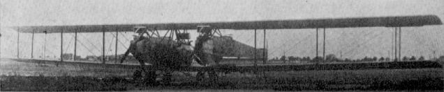
Siemens-Schuckert L I (G III)
Siemens-Schuckert D VI
Last of the S.S.W. fighters, the D VI parasol was due to replace the D IV on the production line, but only two machines (3054 and 3055/17) were completed. The strut-braced wing carried overhung balanced ailerons and, peculiarly, increased in depth of section from centre-section outwards to about mid span of each panel, then decreased in depth again towards the tips. A jettisonable fuel tank underneath the fuselage was a unique feature of this aeroplane. Flight trials were carried out from February to May 1919, during which period one machine was destroyed, but not before very encouraging climb and speed figures had been achieved. Engine, 160 h.p. Siemens-Halske Sh IIIa. Span, 9.37 m. (30 ft. 8 7/8 in.). Length, 6.5 m. (21 ft. 4 in.). Area, 12.46 sq.m. (135 sq.ft.). Weights: Empty, 540 kg. (1,188 lb.). Loaded, 710 kg. (1,562 lb.). Speed, 220 km.hr. (137.5 m.p.h.). Climb, 6,000 m. (19,680 ft.) in 16 min. Duration, 2 hr.
Last of the S.S.W. fighters, the D VI parasol was due to replace the D IV on the production line, but only two machines (3054 and 3055/17) were completed. The strut-braced wing carried overhung balanced ailerons and, peculiarly, increased in depth of section from centre-section outwards to about mid span of each panel, then decreased in depth again towards the tips. A jettisonable fuel tank underneath the fuselage was a unique feature of this aeroplane. Flight trials were carried out from February to May 1919, during which period one machine was destroyed, but not before very encouraging climb and speed figures had been achieved. Engine, 160 h.p. Siemens-Halske Sh IIIa. Span, 9.37 m. (30 ft. 8 7/8 in.). Length, 6.5 m. (21 ft. 4 in.). Area, 12.46 sq.m. (135 sq.ft.). Weights: Empty, 540 kg. (1,188 lb.). Loaded, 710 kg. (1,562 lb.). Speed, 220 km.hr. (137.5 m.p.h.). Climb, 6,000 m. (19,680 ft.) in 16 min. Duration, 2 hr.
Siemens-Schuckert R VIII
After completion of the R I to R VII series of three-engined bombers, the S.S.W. design team applied their knowledge to producing plans for the ambitious, six-engined R VIII. Construction was begun in February 1918 on two of these colossal machines, R 23/16 and R 24/16, but only the first aircraft was ever completed, and even that never flew. During ground trials early in 1919 the transmission gear failed, a propeller flying to pieces and extensively damaging the airframe, which was never rebuilt, due to the restrictions of the Armistice. Engines, six 300 h.p. Basse and Selve BuS IV. Span, 48 m. (157 ft. 6 in.). Length, 21.7 m. (71 ft. 2 3/8 in.). Height, 7.4 m. (24 ft. 3 3/8 in.). Area, 440 sq.m. (4,752 sq.ft.). Weights: Empty, 10,500 kg. (23,100 lb.). Loaded, 15,900 kg. (34,980 lb.). Speed, 125 km.hr (78.125 m.p.h.) estimated. Ceiling, 4,000 m. (13,120 ft.), estimated. Duration, 8 hr., estimated.
After completion of the R I to R VII series of three-engined bombers, the S.S.W. design team applied their knowledge to producing plans for the ambitious, six-engined R VIII. Construction was begun in February 1918 on two of these colossal machines, R 23/16 and R 24/16, but only the first aircraft was ever completed, and even that never flew. During ground trials early in 1919 the transmission gear failed, a propeller flying to pieces and extensively damaging the airframe, which was never rebuilt, due to the restrictions of the Armistice. Engines, six 300 h.p. Basse and Selve BuS IV. Span, 48 m. (157 ft. 6 in.). Length, 21.7 m. (71 ft. 2 3/8 in.). Height, 7.4 m. (24 ft. 3 3/8 in.). Area, 440 sq.m. (4,752 sq.ft.). Weights: Empty, 10,500 kg. (23,100 lb.). Loaded, 15,900 kg. (34,980 lb.). Speed, 125 km.hr (78.125 m.p.h.) estimated. Ceiling, 4,000 m. (13,120 ft.), estimated. Duration, 8 hr., estimated.
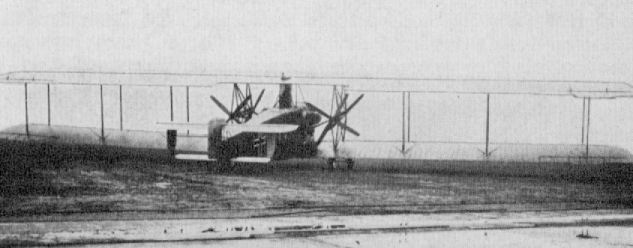
Siemens-Schuckert R VIII R23/16
Zeppelin C I and C II (Ja)
These two two-seaters were designed by Paul Jaray and constructed at the Zeppelin airship factory at Friedrichshafen during the autumn of 1917. Only two C Is were built. These were wooden machines with fabric covering. The C II was virtually the same aircraft, except that the balances on the tail surfaces were dispensed with and now constructed with a metal frame. Six were completed during the winter of 1917-18. Twenty C IIs had been completed by the Armistice, and their destruction was ordered by the Allied Control Commission, but their sale to Switzerland was tacitly permitted. They were flown by the Swiss Air Force until 1928 and were well liked by their crews.
Engine, 240 h.p. Maybach Mb IV. Span, 120 m. (39 ft. 4 1/2 in.). Length, 7,925 m. (26 ft. 0 in.). Height, 3.585 m. (11 ft. 9 in.). Weights: Empty, 987.5 kg. (2,173 lb.). Loaded, 1,455 kg. (3,201 lb.). Speed ca. 200 km.hr. (125 m.p.h.). Climb to 5.000 m. (16,400 ft.) in 33 min.
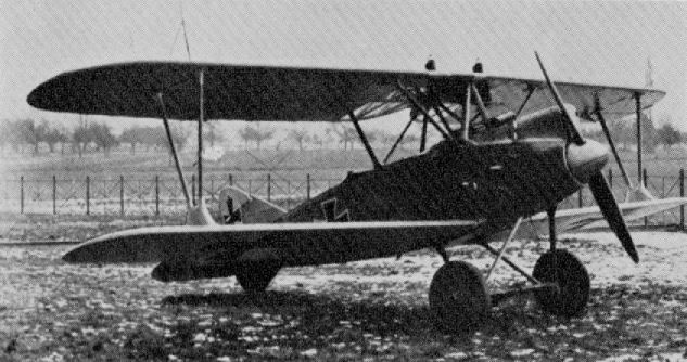
Zeppelin C I
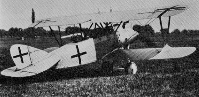
Zeppelin C II
Zeppelin-Lindau (Dornier) Rs I
This gigantic flying-boat was conceived by Claude Dornier before the First World War. Count von Zeppelin was so impressed with this young engineer's latent brilliance that he authorised special facilities for him to develop his ideas at Friedrichshafen. Dornier's research eventually produced encouraging results, which were looked upon more as essays in techniques from which valuable lessons could be learned rather than designs suitable for production aircraft.
Construction on Rs I was started in January 1915, and the machine was launched in October of that year. The three engines were buried in the hull and drove three pusher airscrews through shaft and bevel-gear transmission. Hull longitudinals and wing spars were of high-tensile steel, the lower part of the hull covering being alloy sheet and the wing covering of fabric. Ribs were of metal, as were the Warren truss arranged interplane struts. These struts converged upon the centre spar of the lower wing, around which the whole cellule could be rotated to adjust the incidence. The Rs I was wrecked before flight trials began, but results thus far obtained were sufficiently encouraging to proceed on the Rs II development.
Engines, three 240 h.p. Maybach Mb IV. Span, 43.5 m. (142 ft. 8 7/8 in.). Length, 29 m. (95 ft. 1 7/8 in.). Height, 7.2 m. (23 ft. 7 1/2 in.). Area, 328.8 sq.m. (3,551 sq.ft.). Weights: Empty, 7,500 kg. (16,500 lb.). Loaded, 10,500 kg. (23,100 lb.).
Zeppelin-Lindau (Dornier) Rs II
Dornier's Rs II differed considerably from his first machine. Construction began in December 1915, and the first flight was made on 30th June 1918. The lower wings were now no more than rudimentary, and this flying-boat was, in effect, a monoplane. The shortening of these wings obviated the tendency for the tips to "dig in", as had been experienced with the Rs I when anything like a swell was running. It had been found, after initial trials, that the widened hull of the Rs II had ample lateral buoyancy of itself. The hull, which was mainly metal skinned except for some of the decking, which was fabric, was also drastically shortened and the tail surfaces carried on tubular steel outriggers. Initially these were of biplane format, but were later modified to monoplane surfaces with twin fins and rudder, both above and below the tailplane.
Engine arrangements were originally as in the first machine, but later power was increased to four engines, and these were mounted in tandem pairs in two power-eggs between the wing and fuselage. Two massive pairs of steel vee struts on each side braced the fabric-covered wing, with its horn-balance ailerons, to the top longeron.
After its trial programme was completed this flying-boat (No. 1433) was dismantled in order that resources might be devoted to the Rs III.
Engines, three 240 h.p. Maybach Mb IV. Span, 33.2 m. (108 ft. 11 1/4 in.). Length, 23.88 m. (78 ft. 4 1/4 in.). Area, 257 sq.m. (2,776 sq.ft.). Weights: Empty, 7,100 kg. (15,620 lb.). Loaded, 9,300 kg. (20,460 lb.).
After modification: Engines, four 240 h.p. Maybach Mb IV. Span. 33.2 m. (108 ft. 11 1/4 in.). Length, 21.7 m. (71 ft. 2 3/8 in.). Area, 257 sq.m. (2,776 sq.ft.). Weights: Empty, 7,180 kg. (15,796 lb.). Loaded, 10,000 kg. (22,000 lb.). Speed, 130 km.hr. (81.25 m.p.h.).
Zeppelin-Lindau (Dornier) V 1
This interesting pusher biplane was built during 1916, and first flew in November of that year. The sesquiplane wing format was unusual, as was the comparatively narrow gap. Tail booms and struts were of steel, and the large egg-like nacelle was fabricated from aluminium sheet. Wing and tail surfaces were fabric covered, but spars and ribs were of metal in uniformity with Dornier's other machines.
Engine fitted was a 160 h.p. Maybach Mb III. Span, 10.55 m. (34 ft. 5 1/2 in.).
Zeppelin-Lindau (Dornier) C I
Another of Dornier's designs which appeared in 1917 was this C I, which was built to test his theory of stressed-skin construction, the fuselage being an all-metal structure with the sheet alloy skin bearing part of the load stresses. The wings were orthodox fabric-covered structures but with aluminium box-spars; in the first version a flush radiator was fitted in the centre-section: in the second version a car-type nose radiator was fitted.
Although the machine failed to meet the performance specifications when officially type tested on 18th March 1918, it provided Dornier with the information he required for his Rs IV fuselage.
Engine, 160 h.p. Mercedes D III. Span, 10.5 m. (34 ft. 5 1/2 in.). Length, 7.42 m. (24 ft. 4 1/8 in.). Height, 2.76 m. (9 ft. 0 3/4 in.). Area, 25.82 sq.m. (279 sq.ft.). Weights: Empty, 728 kg. (1,712 lb.). Loaded, 1,068 kg. (2,350 lb.). Speed, ca. 150 km.hr. (93.75 m.p.h.). Climb, 1,000 m. (3,280 ft.) in 4.5 min., 3,000 m. (9,840 ft.) in 18 min., 5,000 m. (16,400 ft.) in 60.4 min. Armament, one Spandau and one Parabellum machine-guns.
Zeppelin-Lindau (Dornier) Rs III
Built between April and November 1917, this third flying-boat of Dornier's was a pure monoplane which incorporated the lessons learned from its two precursors. Tail booms were now replaced by a square-section fuselage of steel longitudinals and alloy frames with fabric covering, mounted on top of the wing.
The short, wide, shallow-draught hull supported the two power eggs, in which the tandem-mounted engines were installed, upon a system of stout steel struts. Further struts, springing from the power eggs, supported the massive wing, which was now braced with cables only. Flettner-type servos now assisted aileron operation. A cumbersome biplane tail assembly was featured which had undergone various modifications during development.
Maiden flight of Rs III (No. 1431) was on 21st October 1917, and a delivery flight from Friedrichshafen to Norderney was made in approximately 7 hours on 19th February 1918, where it underwent further trials at that station and also at Warnemunde. The aircraft survived the war, but whether it made any operational sorties has not been established; it is recorded as having made one flight of at least 10 hours' duration.
Engines, four 245 h.p. Maybach Mb IVa. Span, 37 m. (121 ft. 4 7/8 in.). Length, 22.75 m. (74 ft. 7 3/4 in.). Height, 8.2 m. (26 ft. 10 7/8 in.). Area, 226 sq.m. (2,441 sq.ft.). Weights: Empty, 7,200 kg. (15,840 lb.). Loaded, 10,670 kg. (23,474 lb.). Speed, 135 km.hr. (84.35 m.p.h.). Climb, 2,000 m. (6,560 ft.). Duration, 10 hr. Armament, three machine-guns.
Zeppelin-Lindau (Dornier) CS I
This experimental two-seat seaplane was built during 1918. It was of all-metal construction except for the fabric-covered wing and cruciform tail surfaces. Ailerons were fitted with Flettner-type servos. The machine was fitted with vee-type eight-cylinder Benz engine, and both nose and side radiator installations were tested. Engine, 195 h.p. Benz Bz IIIb. Span, 13.18 m. (43 ft. 2 7/8 in.). Area, 29.8 sq.m. (322 sq.ft.). Weights: Empty, 960 kg. (2,112 lb.). Loaded, 1,479 kg. (3,254 lb.). Speed, 150 km.hr. (93.75 m.p.h.). Armament, one Spandau and one Parabellum machine-guns.
This experimental two-seat seaplane was built during 1918. It was of all-metal construction except for the fabric-covered wing and cruciform tail surfaces. Ailerons were fitted with Flettner-type servos. The machine was fitted with vee-type eight-cylinder Benz engine, and both nose and side radiator installations were tested. Engine, 195 h.p. Benz Bz IIIb. Span, 13.18 m. (43 ft. 2 7/8 in.). Area, 29.8 sq.m. (322 sq.ft.). Weights: Empty, 960 kg. (2,112 lb.). Loaded, 1,479 kg. (3,254 lb.). Speed, 150 km.hr. (93.75 m.p.h.). Armament, one Spandau and one Parabellum machine-guns.
Zeppelin-Lindau (Dornier) D I
This single-seat fighter was another of Claude Dornier's research essays, this time into the realm of cantilever-wing construction. About two-thirds of the wings were aluminium sheet-covered, over alloy ribs and spars, forming a torsion-box structure. The remainder of the wings, from the rear spar to trailing edge, were fabric-covered, as were also the unbalanced ailerons. The fuselage was an all-metal, stressed-skin assembly, incorporating the vertical fin, all other tail surfaces being fabric-covered. Other unique features were the - apparent - single-leg undercarriage and the streamlined jettisonable fuel tank slung underneath the fuselage.
Although not listed in the official list of types participating in the second D types Competition at Adlershof in the summer of 1918, the Zeppelin D I was among several other types submitted for evaluation by Front Line pilots, as an adjunct to the D Competition. The machine was then fitted with Mercedes D III engine, and when being flown by Oblt. Reinhard in July 1918 it shed a top wing with fatal results. Another aircraft, with B.M.W. engine installed, competed in the third D types Competition (which was for B.M.W.-powered aircraft only). Performance was disappointing, and in speed the Zeppelin fighter was surpassed by seven other types. Bongartz' succinct report said: "Does not possess characteristics of a modern fighter. Ailerons too heavy."
Engine: 185 h.p. B.M.W. IIIa. Span, 7.8 m. (25 ft. 7 1/8 in.). Length, 6.37 m. (20 ft. 11 in.). Area, 18.7 sq.m. (202 sq.ft.). Weights: Empty, 710 kg. (1,562 lb.). Loaded, 890 kg. (1,958 lb.). Armament, twin Spandau machine-guns.
N.B. Two Zeppelin D Is were taken to the U.S.A. after the war and evaluated by the Army and Navy respectively.
Zeppelin-Lindau (Dornier) Rs IV
Last of the war-time Dornier flying-boats, the Rs IV was launched in October 1918, construction having started the previous January. In cross-section the hull was much narrower than formerly, and lateral stability on the water was achieved by lifting-cum-flotation surfaces, which were later to become a famous Dornier flying-boat characteristic, in use right up to the Second World War and later termed sponsons. The high-slung fuselage was now metal skinned, and a much simplified tail assembly of cruciform pattern was designed.
With the narrower hull, the power eggs perforce were closer together and were slightly staggered to allow maximum-diameter airscrews to be used. This feature improved asymmetric flight characteristics. After the Armistice No. 8801, which was Rs IV's Naval No., was dismantled during 1919.
The lessons learned by Dornier from this four-year research programme were culminated in the many successful commercial flying-boats built between the two World Wars.
Engines, four 245 h.p. Maybach Mb IVa. Span, 37 m. (121 ft. 4 7/8 in.). Length, 22.3 m. (73 ft. 2 in.). Height, 8.55 m. (28 ft. 0 5/8 in.). Area, 226 sq.m. (2,441 sq.ft.). Weights: Empty, 7,000 kg. (15,400 lb.). Loaded 10,700 kg. (23,540 lb.). Speed, 145 km.hr. (90.625 m.p.h.).
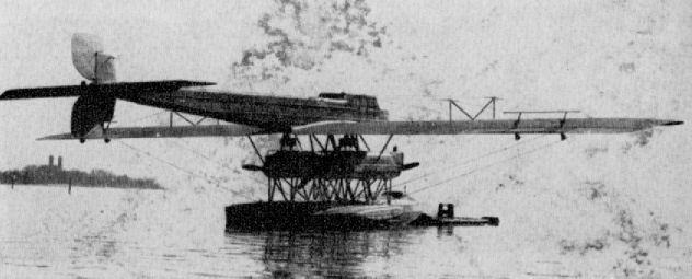
Zeppelin-Lindau (Dornier) Rs IV
Zeppelin-Staaken V.G.O. I
First of the Zeppelin "Giants", the V.G.O. I (Versuchs Gotha Ost) made its first flight on 11th April 1915. It was a three-engined machine - two pusher, one tractor - with gun positions at the front end of each engine nacelle. The machine set a standard of size and construction that was maintained throughout the "Giant" series, except for detail refinements, reference to which may be found in the main text. Built for the German Navy, the machine bore the serial R.M.L. 1 and served on the Eastern Front; it was later returned to Staaken and two additional engines were fitted in the nacelles. In this guise the aircraft crashed at Staaken while under test, two crew members, Vollmoller and Klein, being killed.
Engines, three 240 h.p. Maybach Mb IV. Span, 42.2 m. (138 ft. 5 5/8 in.). Length, 24 m. (78 ft. 9 in.). Height, 6.6 m. (21 ft. 7 7/8 in.). Area, 332 sq.m. (3,586 sq.ft.). Weights: Empty, 6,520 kg. (14,344 lb.). Loaded, 9,520 kg. (20,944 lb.). Speed, 110 km.hr. (68.75 m.p.h.). Climb, 2,000 m. (6,560 ft.) in 39 min. Armament, four machine-guns.
Data after modification to five 245 h.p. Maybachs. Weights: Empty, 7,450 kg. (16,390 lb.). Loaded, 11,485 kg. (25,267 lb.). Speed, 130 km.hr. (81.25 m.p.h.). Climb, 3,000 m. (9,840 ft.) in 60 min.
N.B. The V.G.O. II was a virtually identical aeroplane, also to the three-engined formula. Serialled R 9/15, it was used on the Eastern Front and later used as a trainer.

V.G.O. I. Attendant personnel lend scale showing how collossal these machines really were.
Zeppelin-Staaken R V
Fifth of the "Giant" prototypes, the R V again rung the changes in the engine arrangement. All five motors were 240 h.p. Maybachs, with reversion to a single power plant in the nose and tandem-mounted engines, now arranged to drive four-blade tractor airscrews, outboard. The nacelles housing the outboard engines were experimentally built of wood and covered in ply-sheet, and due to the tractor propeller arrangement, the machine-gun positions were necessarily transferred to the rear. An additional machine-gun emplacement was provided in a streamlined nacelle, also of plywood, positioned in the centre of the top wing and known as the Schwalbenest (Swallow's nest). This machine, serialled R 13/15, saw service on the Western Front. Engines, five 240 h.p. Maybach Mb IV. Span, 42.2 m. (138 ft. 5 5/8 in.). Length, 230 m. (75 ft. 5 5/8 in.). Height, 6.8 m. (22 ft. 3 3/4 in.). Area, 332 sq.m. (3,586 sq.ft.). Weights: Empty, 9,450 kg. (20,790 lb.). Loaded, 13,010 kg. (28,622 lb.). Speed, 135 km.hr. (84.35 m.p.h.). Climb, 3,000 m. (9,840 ft.) in 46 min. Armament, five machine-guns.
Fifth of the "Giant" prototypes, the R V again rung the changes in the engine arrangement. All five motors were 240 h.p. Maybachs, with reversion to a single power plant in the nose and tandem-mounted engines, now arranged to drive four-blade tractor airscrews, outboard. The nacelles housing the outboard engines were experimentally built of wood and covered in ply-sheet, and due to the tractor propeller arrangement, the machine-gun positions were necessarily transferred to the rear. An additional machine-gun emplacement was provided in a streamlined nacelle, also of plywood, positioned in the centre of the top wing and known as the Schwalbenest (Swallow's nest). This machine, serialled R 13/15, saw service on the Western Front. Engines, five 240 h.p. Maybach Mb IV. Span, 42.2 m. (138 ft. 5 5/8 in.). Length, 230 m. (75 ft. 5 5/8 in.). Height, 6.8 m. (22 ft. 3 3/4 in.). Area, 332 sq.m. (3,586 sq.ft.). Weights: Empty, 9,450 kg. (20,790 lb.). Loaded, 13,010 kg. (28,622 lb.). Speed, 135 km.hr. (84.35 m.p.h.). Climb, 3,000 m. (9,840 ft.) in 46 min. Armament, five machine-guns.
Zeppelin-Staaken V.G.O. III
Due to the V.G.O. I and II not being powerful enough, the V.G.O. III was powered with six engines; two mounted side-by-side in the nose and two in each nacelle mounted tandem fashion driving a single pusher airscrew. Serialled R 10/15, the machine was sometimes known as R III and used by Rfa 500 on the Eastern Front. Engines, six 160 h.p. Mercedes D III. Span, 42.2 m. (138 ft. 5 5/8 in.). Length, 24.5 m. (80 ft. 4 3/4 in.). Height, 6.8 m. (22 ft. 3 3/4 in.). Area, 332 sq.m. (3,586 sq.ft.). Weights: Empty, 8,600 kg. (18,920 lb.). Loaded, 11,600 kg. (25,520 lb). Speed, 120 km.hr. (75 m.p.h.). Climb, 2,000 m. (6,560 ft.) in 29 min. Armament, five machine-guns.
Zeppelin-Staaken R IV
This machine was the first of the Staaken "Giants" to bear the official R designation. It was similar in most respects to the V.G.O. III, adhering to the same six-engined formula, but with the more powerful 220 h.p. Benz engines fitted in the nacelles, driving single four-bladed airscrews. Serialled R 12/15, this aircraft saw service on both Eastern and Western fronts. Engines, six - two 160 h.p. Mercedes D III in nose, four 220 h.p. Benz Bz IV in nacelles. Span, 42.2 m. (138 ft. 5 5/8 in.). Length, 23.2 m. (76 ft. 1 1/2 in.). Height, 6.8 m. (22 ft. 3 3/4 in.). Area, 332 sq.m. (3,586 sq.ft.). Weights: Empty, 8,772 kg. (19,298 lb.). Loaded, 13,035 kg. (28,677 lb.). Speed, 125 km.hr. (78.125 m.p.h.). Climb, 3,000 m. (9,840 ft.) in 89 min. Duration, 6-7 hr. Armament, six or seven machine-guns.
0 min. Armament, five machine-guns.
Zeppelin-Staaken R VII
The R VII was a development of the R IV, and differed very little visibly from that machine. The same engine arrangement was adhered to, but there was some alteration in the system of bracing struts between the tailplanes. Serialled R 14/15, the R VII crashed while on a delivery flight to the Front. Engines, two 160 h.p. Mercedes D III in nose, four 220 h.p. Benz Bz IV in nacelles. Span, 42.2 m. (138 ft. 5 5/8 in.). Length, 22.1 m. (72 ft. 6 1/4 in.). Height, 6.8 m. (22 ft. 3 3/4 in.). Area, 332 sq.m. (3,586 sq.ft.). Weights: Empty, 8,923 kg. (19,741 lb.). Loaded, 12.953 kg. (28,497 lb.). Speed, 130 km.hr. (81.25 m.p.h.). Climb, 3,000 m. (9,840 ft.) in 50 min. Armament, five machine-guns.
Zeppelin-Staaken Type "L" Seaplane
This machine, which was allocated the Naval No. 1432, was virtually an R VI type mounted upon massive duralumin floats some 13 m. (42 ft. 7 7/8 in.) in length, divided into twelve water-tight compartments. The aircraft was wrecked during trials. Engines, four 260 h.p. Mercedes D IVa. Span, 42.2 m. (135 ft. 5 5/8 in.). Length, 22.2 m. (72 ft. 10 3/8 in.). Height, 7.38 m. (24 ft. 2 5/8 in.). Area, 360 sq.m. (3,888 sq.ft.). Weights: Empty, 8,400 kg. (18,480 lb.). Loaded, 11,800 kg. (25,960 lb.). Speed, 125 km.hr. (78.125 m.p.h.). Climb, 1,780 m. (5,839 ft.), in 60 min. Ceiling, 2,500 m. (8,200 ft.). Duration, 10 hr. Armament, four machine-guns.
This machine, which was allocated the Naval No. 1432, was virtually an R VI type mounted upon massive duralumin floats some 13 m. (42 ft. 7 7/8 in.) in length, divided into twelve water-tight compartments. The aircraft was wrecked during trials. Engines, four 260 h.p. Mercedes D IVa. Span, 42.2 m. (135 ft. 5 5/8 in.). Length, 22.2 m. (72 ft. 10 3/8 in.). Height, 7.38 m. (24 ft. 2 5/8 in.). Area, 360 sq.m. (3,888 sq.ft.). Weights: Empty, 8,400 kg. (18,480 lb.). Loaded, 11,800 kg. (25,960 lb.). Speed, 125 km.hr. (78.125 m.p.h.). Climb, 1,780 m. (5,839 ft.), in 60 min. Ceiling, 2,500 m. (8,200 ft.). Duration, 10 hr. Armament, four machine-guns.
Zeppelin Staaken R VI
Without doubt the most remarkable aircraft built by the Germans during the First World War were the "R" (Riesenflugzeug) type giant machines with four, five or six engines. The eventual degree of reliability that was attained was a noteworthy achievement when it is considered that everything connected with these unique aircraft had to be developed and produced from scratch. There was no previous experience in the design of aircraft of such gargantuan proportions. As an example of just one of the many difficulties, which had to be faced, that of engine failure may be instanced. Many of the first engines fitted in the Giants had been used with excellent reliability in airships, but in the aircraft they blew up (often literally) with monotonous regularity. This failure was eventually discovered to be due to the fact that the engines were called upon to produce upwards of 1,200 r.p.m. for considerable periods on take-off and climb, whereas in airship installation they were never-or rarely-called upon for more than a steady 800 r.p.m.
Undercarriage problems too were a constant headache, again due to there being no previous material of this size to draw upon and the fact that stressing problems were not fully understood. However, mainly trial and error and "guestimated" experiments brought a degree of reliability. A.E.G., D.F.W., Linke-Hofmann, S.S.W. and Zeppelin Staaken all built original designs, but it was only the latter firm's machine that was developed into a series production type, this being the R VI. All others remained prototypes, but the majority of these also saw operational service in varying degrees.
The Zeppelin Staaken R types had been developed, with varying engine permutations, from the V.G.O. I, which first flew in April 1915, to the R VI, in which production version it had four 245 h.p. Maybach or 260 h.p. Mercedes engines mounted in tandem pairs. The Zeppelin Fluzeugbau had moved to Staaken, near Berlin, in the summer of 1916, having transferred from Gotha-Ost, and it was there the majority of the building and development work was carried out.
Of the eighteen R.VIs completed (R 25-39 and R 52-54), six were built by Aviatik, seven by Schutte Lanz and four by O.A.W. All except R 30, which was an experimental supercharged model, saw operational service with Riesenflugzeugabteilungen 500 and 501 on the Western Front and operated from the Ghent area.
Construction of these monster machines, which spanned almost 140 ft., was a complicated and lengthy process, and the total number of man-hours must have been prodigious. A brief technical description follows, but for truly comprehensive coverage of these aircraft the serious student is referred to The German Giants, by Haddow and Grosz.
The fuselage was of wooden construction and basically a fabric-covered, braced, box-girder. The upper longerons were in a horizontal plane on a level with the airscrew axis for almost the whole of their length. The lower longerons were parallel as far back as the gun position, where they swept up in a straight taper to join the upper longerons in a horizontal knife-edge. A gun position was provided in the extreme nose, and in this cockpit the bomb- release gear was located. Aft of this position the two pilots sat side by side with dual wheel controls, followed by the radio operator's and navigator's compartments. On a level with the leading edges of the wings, provision was made for a mechanic, who was mainly responsible for controlling the emptying of the eight cylindrical fuel tanks so that trim was not upset. The spacious dorsal cockpit accommodated two gunners, who were also able to fire below the fuselage through a ventral position in the floor. The section of space for stowage of eighteen 100 kg. bombs with a through passageway in order to communicate with the fore part of the fuselage.
Of vast proportions, the wings were otherwise of orthodox construction and based on two main spars, which were of double box-girder section. The center panel of both wings extended as far as the engine nacelles and was without dihedral, as was the whole of the upper wing. The outer panels of the lower wing had marked dihedral. Taper on the wings was slight and on the leading edges only. Steel-tube compression members were positioned at interplane strut locations. The ribs were closely spaced and built-up lattice-girder structures, with top and bottom spruce flanges held together by double-lath web strips disposed zig-zag fashion. Ailerons were of steel-tube framework and, being unbalanced, must have demanded considerable muscle power-small wonder two pilots were required. All wing surfaces were fabric covered.
Streamlined engine nacelles of alloy stringers and panels were supported by twin "A" frames of steel tube located at the spar stations, to which, in turn, the engine bearers were attached by a complex frame of sheet steel and wood. The tandem-mounted engines were fitted with gear-boxes, and the airscrews of the rear engines were driven through extension shafts. A small cockpit was located between the engines wherein the flight mechanic endured his lonely vigil. All struts were of circular-section steel tube faired off with three-ply sheet.
An unusual feature of the Zeppelin Staaken R.VI was the wide use of aluminum in the construction of the tail. This was a huge biplane structure, the size of a single-seat fighter, with a swept leading edge to the tailplanes and inverse taper at the tips of the unbalanced elevators. The tailplane section was of a reverse camber. The triple rudders were the only control surfaces to be balanced, and all were fitted with fixed fin surfaces.
Although no less than eighteen wheels were used in the undercarriage, all three chassis were relatively simple vee-type structures. The axles of the main chassis, located immediately under the engine nacelles, were thicker than those of a railway wagon and supported two pairs of twin wheels each end, which must have caused considerable drag. Axles were bound to the steel-tube vees with elastic cord. The tailskid was a conventional component fabricated from a single piece of ash and shod with steel.
June 1917 saw the delivery of the first Staaken R.VI "R 25", soon to be followed by "R 26" in July. Many and varied were the sorties made by these Giant aeroplanes, including a considerable number of attacks on England, the first being on 17th September 1917, and even a raid on Le Havre, which involved a round trip of some 800 km. For a raid of this length a reduced bomb load was carried, probably in the nature of 750 kg. All bomb loads were in direct proportion to the fuel carried, which again was related to the range required. For raids of short duration 2,000 kg. of bombs could be carried, but the average load for a long-range sortie was about half that weight. The 100 kg. bombs were stowed internally, but the larger 300 and 1,000 kg. bombs (which were the largest bombs to be dropped from any aeroplane during the First World War) were carried under the belly, only partially enclosed.
The R 25, the first of the Staaken R.VIs to be supplied, made an intrepid solo raid upon London during the night of 17th/ 1 8th February 1918, and with considerable skill scored a direct hit upon St. Pancras railway station. R 26 succeeded in making no less than twenty varied sorties, during which a total of some 26,000 kg. of bombs was dropped.
The R.VI, R 39, was one of five Giants raiding England on the night of 16th - 17th February and dropped the first 1,000 kg. bomb on Britain, hitting the Royal Hospital, Chelsea. The same aircraft dropped the second 1,000 kg. bomb on the night of 7th - 8th March 1918, destroying houses in Warrington Crescent, Maida Vale.
Rfa 501 made a total of eleven raids on England between 18th December 1917 and 20th May 1918. They dropped 27,190 kg. of bombs (compared with 84,745 kg. dropped by Gothas in twenty-two raids) and lost no aircraft due to Allied action.
A seaplane variant of the R.VI was built for the Navy.
Description: Multi-engined giant bomber. Crew of seven.
Manufacturers: Zeppelin Werke Staaken G.m.b.H. Staaken bei Berlin (Staak.).
Sub-contractors: Automobil und Aviatik A.G., Leipzig-Heiterblick
Ostdeutsche Albatros Werke G.m.b.H.,
Schneidemuhl Luftfahrzeugbau Schutte-Lanz, Mannheim.
Power Plant: Four 245 h.p. Maybach Mb IV 6-cylinder in-line water-cooled engines.
or
Four 260 h.p. Mercedes D.IVa, 6-cylinder in-line water-cooled engines.
Dimensions
Span 42.2 m. (138 ft. 5 5/8 in.)
Length 22.1 m. (72 ft. 6 1/4 in.)
Height 6.3m. (20 ft. 8 in.)
Area 332 sq.m. (3,595 sq.ft.)
Weights
Empty 7,921 kg. (17,426 lb.)
Loaded 11,848 kg. (26,066 lb.)
Performance:
Max speed 135 km.hr. (84.35 m.p.h.)
Climb 3,000 m. (9,840 ft.) 43 min
Ceiling 4,320 m. (14,170 ft.)
Duration 7-10 hr.
Armament: Four manually operated Parabellum machine-guns in nose,
dorsal and ventral positions.
Various bomb loads carried to suit tactical or strategic requirement.
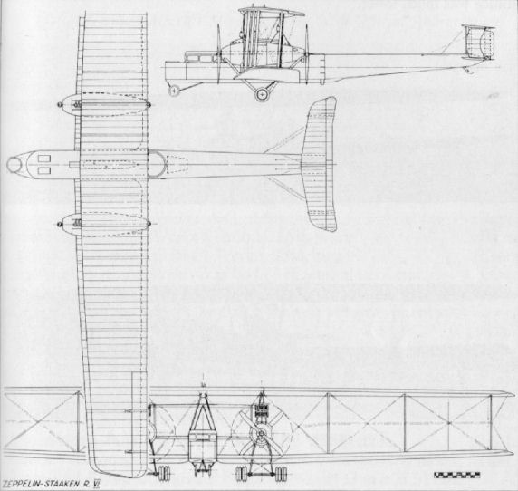
Zeppelin-Staaken R XV
Development of the Staaken "Giants" continued in the R XIVs and R XVs of 1918, which, as far as can be ascertained, appeared not to differ. Three R XIVs were built, R 43/16-R 45/16, of which the first numbered machine was shot down by Capt. Yaille of 151 Squadron R.A.F. R 45/16 was used for experiments with control positions. The R XVs were serialled R 46/16-R 48/16, but were probably completed too late to see any service use. All machines were five-engined "Giants" and differed from previous aircraft in each engine having its own individual airscrew, making three tractors and two pushers, and in consequence the abandonment of gun positions in the nacelles. A large central fin was now included in the tail assembly in similar manner to the later R VIs. Engines, five 245 h.p. Maybach Mb IV. Span, 42.2m. (138 ft. 5 5/8 in.). Length, 22.5 m. (73 ft. 10 in.). Height, 6.3 m. (20 ft. 8 in.). Area, 334 sq.m. (3,607 sq.ft.). Weights: Empty, 10,350 kg. (22.770 lb.). Loaded, 14,450 kg. (31,790 lb.). Speed, 130 km.hr. (81.25 m.p.h.). Climb, 3,000 m. (9,840 ft.) in 70 min. Armament, five machine-guns.
Development of the Staaken "Giants" continued in the R XIVs and R XVs of 1918, which, as far as can be ascertained, appeared not to differ. Three R XIVs were built, R 43/16-R 45/16, of which the first numbered machine was shot down by Capt. Yaille of 151 Squadron R.A.F. R 45/16 was used for experiments with control positions. The R XVs were serialled R 46/16-R 48/16, but were probably completed too late to see any service use. All machines were five-engined "Giants" and differed from previous aircraft in each engine having its own individual airscrew, making three tractors and two pushers, and in consequence the abandonment of gun positions in the nacelles. A large central fin was now included in the tail assembly in similar manner to the later R VIs. Engines, five 245 h.p. Maybach Mb IV. Span, 42.2m. (138 ft. 5 5/8 in.). Length, 22.5 m. (73 ft. 10 in.). Height, 6.3 m. (20 ft. 8 in.). Area, 334 sq.m. (3,607 sq.ft.). Weights: Empty, 10,350 kg. (22.770 lb.). Loaded, 14,450 kg. (31,790 lb.). Speed, 130 km.hr. (81.25 m.p.h.). Climb, 3,000 m. (9,840 ft.) in 70 min. Armament, five machine-guns.
Zeppelin-Staaken R XVI (Av)
Early in 1918 the new Benz Bz VI developing 530 h.p. became available, and Aviatik were chosen to fit these engines to the basic Staaken R VI airframe. This was due partly to the parent firm being otherwise fully committed and partly to Aviatik's experience in the building of six R VI machines under licence.
Three aircraft with the Benz engines were ordered, R 49 to R 51, designated Staaken R XVI (Av) and were the ultimate Staaken development. R 49 was completed in October 1918 but smashed its landing gear on a test flight and rebuilding cannot be confirmed. R 50 was finished after the war as a civil machine, but was soon dismantled. Although R 51 was well advanced in construction, it was never completed.
Engines, two 220 h.p. Benz IVa and two 530 h.p. Benz VI driving tractor and pusher airscrews in two nacelles. Spinners were fitted, a refinement not seen on "Giants" built by the parent firm. Span, 42.2 m. (138 ft. 5 1/2 in.). Length, 22.5 m. (73 ft. 10 in.). Height, 6.5 m. (21 ft. 4 1/4 in.). Speed, 130 km.hr. (80.8 m.p.h.). Ceiling, 3,710 m. (12,172 ft.) in 76.5 min.
Zeppelin-Staaken Type 8301 Seaplane
Three seaplanes of this type were completed, Naval Nos. 8301, 8303 and 8304; the completion of 8302 is not confirmed. Although an R VI type wing cellule was used, with balanced ailerons, a completely new fuselage was designed and suspended almost midway between the wings. The tail surfaces employed were as those on the R XIV and R XV land machines. Engines, four 260 h.p. Mercedes D IVa. Span, 42.2 m. (138 ft. 5 5/8 in.). Length, 21 m.(68ft. 10 7/8 in.). Height, 6.8 m. (22 ft. 3 3/4 in.). Area, 340.5 sq.m. (3,677 sq.ft.). Weights: Empty, 9,000 kg. (19,800 lb.). Loaded, 12,500 kg. (27,500 lb.). Speed, 130 km.hr. (81.25 m.p.h.). Climb, 3,000 m. (9,840 ft.) in 54 min. Duration, 10 hr. Armament, five machine-guns.
Zeppelin-Staaken Type 8301
Naval seaplane No. 8301 underwent flight trials fitted with land undercarriage chassis. Engines, four 260 h.p. Mercedes D IVa. Dimensions were same as for seaplane except for height, which would naturally be less, and wing area was the same. No other data available.