
Книги
Putnam
J.Cynk
Polish Aircraft 1893-1939
70
J.Cynk - Polish Aircraft 1893-1939 /Putnam/
Warchalowski System Biplanes
Autobiplan Warchalowski System Type I and Type II. The most successful and active among the Polish aviation engineers before 1914 was Adolf Warchalowski, who worked in Vienna and played a prominent part in the early history of flying in Austria. After graduating in 1909, in October of the same year Adolf Warchalowski was sent to France to collect a Henri Farman biplane, which was ordered by Werner & Pfleiderer, an Austrian engineering concern managed by his older brother August.
Receiving the Farman on 20 November, 1909, Adolf made a few ground runs and a short flight, at the end of which the machine was slightly damaged on landing. The biplane was subsequently dismantled and transported to Wiener-Neustadt aerodrome where it was repaired and reassembled by Autoplan-Werke, a newly formed division of the Werner & Pfleiderer company which also acquired the licence for the model. Beginning systematic training on the Farman from Wiener-Neustadt on 24 January, 1910, Adolf Warchalowski soon became the best known and respected pilot in Vienna and achieved one success after another. On 17 February, with a passenger on board, he stayed in the air 25 min 22 sec while circling the aerodrome ten times. As this flight was not observed officially, two days later he repeated the duration attempt, winning the Gerngross Prizes for the first 15-minute and the first passenger-carrying five-minute flights in Austria and establishing the first two officially recognized Austrian national records. On 1 March he stayed in the air for 1 hr 2 min 4 sec, a new Austrian record; on 5 March he won the Austrian Aeroclub Prize for the first 10 km (6.2 mile) cross-country flight; and on 22 April he was granted Austrian Pilot's Certificate No. 1.
Upon his return from France Adolf Warchalowski had begun work on his own development of the Henri Farman biplane. Laying the main emphasis on safety and ease of handling rather than on speed, he invented an ingenious landing gear (Austrian Patent No. 50,756) consisting of a system of curved, flexible wooden rods which could absorb very strong impacts without damage, and evolved special flexible Zanonia-shaped wingtips which improved control and stability. These two novel features became the hallmarks of all future Warchalowski System designs, and the landing gear, proving vastly superior to the existing rigid undercarriage designs, was also employed on the Autoplan-built Farmans.
At the beginning of 1910 Autoplan-Werke began construction of Pischof's monoplane, which was named the Vindobona I, and two of Warchalowski's biplanes, this latter model being initially referred to as the Vindobona II. The Vindobona biplanes, both powered by 50 hp Gnome seven-cylinder rotary engines driving pusher airscrews, soon became widely known as the Autobiplan Warchalowski System Type I and Type II. On 9 May, 1910, the Type I with Adolf Warchalowski at the controls took-off for the first time from Wiener-Neustadt aerodrome and despite unfavourable weather made three short but completely successful flights that day, thus becoming the first aeroplane designed by a Pole to achieve a sustained and fully controlled flight. The Type II followed it into the air on 29 May, this machine differing from its predecessor in having revised wingtips, modified wings with two narrow bays (instead of a single, wider one) on each side of the fuselage frame to improve the rigidity of the structure, and the new, Warchalowski-designed controls. These comprised a central T-shaped control stick (which operated control surfaces on the wing and elevators) and a normal rudder bar, and replaced the more complicated Farman system employed on the Type I. The machine frequently flew with a detachable, miniature basket-type nacelle which protected the pilot's legs.
Various refinements were progressively introduced to both models. Available photographs indicate that the Type I was provided with a single additional interplane strut in the middle of the wing-bay leading edge. This was later supplemented by another interplane strut connecting the rear spars, which complemented the division of the original single bays into two. It appears that both aircraft were subsequently fitted with improved rear fuselage frames and their wingtips and tail surfaces underwent some alterations.
In the summer and autumn of 1910 the Warchalowski Types participated in a number of contests and meetings showing remarkably creditable performance. Although at that time Poland was not recognized as a separate state (the southern regions of the partitioned country were incorporated into the Austro-Hungarian Empire), Adolf Warchalowski entered for the great international Budapest Meeting (held 5-17 June, 1910) as the representative of Poland, as recorded in the official competitors list which was published in Fhigsport 1910, No. 10, p. 313. The fact that the holder of the Austrian Pilot's Certificate No. 1 was to appear at Budapest in Polish colours, with all the political implications that entailed, could not have pleased the Austrians. Warchalowski evidently yielded to various pressures, for during the meeting he was officially referred to only as an Austrian. In passing, it is worthy of note that Poles played an important role in the creation of the Austrian flying movement and held several important positions in the Austrian Aeroclub, the Polish influence being reflected by the fact that the Austrian pilots' certificates, printed in six languages, included Polish.
During the Budapest Meeting, which attracted 49 contestants, from Austria, France, Germany, Hungary, Italy and Russia, and included such names as Illner, Chavez, Latham and Paulhan, Adolf Warchalowski (Competitor No. 37) flying one of his biplanes (both of which were in Budapest at his disposal) won a number of heats and in the final results gained three third places (for distance, slow-flying and take-off) and one fourth place (for endurance). At the end of the meeting the Grand Duchess Augusta and the Grand Duke Josef of Austria had their first flying experiences as passengers with Adolf Warchalowski on his Autobiplans, and during the following months various members of the Emperor's family and court and other prominent personages were given flights by him.
In July 1910, during the Wiener-Neustadt Meetings, Adolf Warchalowski took several prizes, including the first prize for a total endurance of 1 hr 42 min 25 sec; the first prize for a maximum speed of 63.4 km/h (39.49 mph) over a 5 km (3.1 mile) course; the first prize for a passenger flight; and the second prize for greatest height. At the same time his brother Karol, who was learning to fly under Adolf's supervision, mainly on the Type I, distinguished himself in the beginner pilots' class. On 27 July Karol received Austrian Pilot's Certificate No. 8 and four days later won the first prize for a height of 112.71 m (369.78 ft).
On Emperor Franz Josefs birthday, 18 August, 1910, Adolf Warchalowski piloting the Type II biplane made an epic flight, the first over the heart of Vienna, which completely captured the imagination of the Austrian public and was widely reported internationally. Taking-off from Wiener-Neustadt after five o'clock in the morning, he rapidly attained a height of 200 m (656 ft) and still climbing headed for the capital city. He was soon over the Imperial castle at Laxenburg and, crossing the Danube, made for the Cathedral of St Stephen which he circled at a height of 700 m (2,296 ft). Then he started off on the journey home, reaching Wiener-Neustadt airfield some 1 1/2 hr after the take-off. During this brilliant cross-country flight, covering some 110 km (68 miles) and completely eclipsing all previous Austrian achievements, Warchalowski bettered a number of existing records, but the lack of approved observers prevented official recognition. He was congratulated by the Emperor and his fine effort was commemorated by a special poster which appeared in the streets of Vienna.
At the end of August 1910, Warchalowski re-engined the Type II with the new 65-70 hp Daimler four-cylinder inline water-cooled engine equipped with a direct-drive Lohner airscrew, and his machine became the fastest on the Wiener-Neustadt airfield. The day of the Emperor's review, 18 September, 1910, was of the greatest significance in the history of Austria's fledgling aviation. The Daimler-powered Type II, decorated with trophies received after the famous Vienna flight, was among the 23 machines massed at Wiener-Neustadt for the occasion. During the flying display which followed the review, Warchalowski made a spectacular dash for the height prize and reached an altitude of 460 m (1,509 ft) above the take-off point (742 m = 2,434 ft absolute), which was duly approved as a new national record, and came second in the out-and-return race. In October Adolf Warchalowski demonstrated the Type II in a number of towns including Moravska Ostrava, Opava and Brno.
The Type I was destroyed on 8 September, 1910, when Adolf Warchalowski was flying just above it; the aircraft, flown by his brother Karol, was caught in the slipstream of Adolf's aircraft and fell to the ground out of control, seriously injuring its pilot. The Type II came to grief on 10 June, 1911, when its airscrew broke away in flight, injuring Josef Sablatnig, who was flying the machine.
Construction: The Autobiplan Warchalowski System Type I and Type II, which in general layout resembled the 1909 Henri Farman model, were two-seat open-frame unstaggered biplanes. The aircraft featured unequal-span wings, with the top plane spanning 11 m (36 ft 1 1/4 in) and the bottom one 8.5 m (27 ft 11 in) in the case of the Type I and 8.8 m (28 ft 10 1/2 in) in the case of the Type II. Except for the flexible Zanonia-shaped upper wingtips, the rearward extensions of which fulfilled the function of ailerons, both wings possessed a constant chord of 2 m (6 ft 7 in). The elevator surface in front of the aircraft had a span of 2.5 m (8 ft 2 3/4 in) and a chord of 1 m (3 ft 3 1/2 in). The lifting tail bay at the rear of the open fuselage frame, with a span of 2.3 m (7 ft 6 3/4 in), consisted of two horizontal surfaces and two rudders. Its top surface (later extended in span to 3.5 m = 11 ft 6 in) was provided with a supplementary elevator which operated in conjunction with the front one. The combined gross area of all lifting surfaces (wings and tail) was 47 sq m (505.9 sq ft). All lifting and control areas were wooden structures covered on both surfaces with rubber-proofed fabric, and the airframe was a composite structure of steel tubing and wooden members, lavishly wire braced. A passenger could be accommodated behind the pilot. Each unit of the patented Warchalowski landing gear, the general principle of which was described earlier, incorporated twin-wheels with a long skid in between. The wheels were attached to the skid with rubber cord so that when they made contact with the ground they drifted back, this having a braking effect. Overall dimensions included a span of 11 m (36 ft 1 1/4 in) and a length of 13.7 m (44 ft 11 1/2 in), while maximum loaded weight was about 450 kg (992 lb). Performance included a maximum speed of about 65 km/h (40.4 mph) and 80 km/h (49.7 mph) for the Gnome- and the Daimler-powered variants respectively.
Autobiplan Warchalowski System Type III, Type IV and Type V. From the time the Warchalowski System biplanes first appeared, the military authorities began to show interest in the design, and the Autoplan-Werke were soon given a contract to train the first military pilots. Adolf Warchalowski having overall responsibility for the programme. Realizing that the Army would soon require a machine suitable for its needs, Adolf Warchalowski began work on a more advanced development of his previous models, which, although closely resembling the Type II, was based upon a 65-70 hp Daimler four-cylinder inline water-cooled engine and possessed an improved powerplant installation and control system and a stronger airframe. The new biplane was finished at the end of October 1910. As the official designation of this and the subsequent Warchalowski designs is not clearly apparent from contemporary descriptions, the author decided to continue with the original designation sequence, the new aircraft becoming accordingly the Type III.
The last day on which pilots could claim the Lower-Austria Prize for duration and distance flights from Wiener-Neustadt was 31 October, 1910, and both Illner and Adolf Warchalowski took-off for their final attempts to win it. Unfortunately, the Type III, which had not yet been properly tested, developed some control and engine difficulties and Warchalowski was forced to interrupt the flight after 57 min 15 sec. On 9 November the Type III was demonstrated to the Chief of the Imperial General Staff and other high-ranking Austrian officers, and this led to an official contract being placed with Autoplan-Werke for a special Military Type. On 27 December the Type III, flown by Warchalowski with Lieut Aztalos on board, made history by flying for 2 hr 16 min 59 sec. a new officially recognized national duration record. The aeroplane, taking-off with a load of 213 kg (470 lb) (two people and fuel) and covering some 180 km (111.8 miles) at an average speed of some 80 km/h (49.7 mph), beat the previous duration record of Illner, which had been established without a passenger and with a load little more than half of that carried by the Type III. A few days later Adolf Warchalowski was acclaimed the best pilot in Austria in 1910 and awarded the Grunhat Prize.
The Warchalowski System Autobiplan Type IV, built to an army specification, was evolved from the Type III. The aircraft, powered by a similar 60 hp Daimler engine, was adapted to carry bigger loads and was provided with a small nacelle protecting the pilot and with wheel-type controls. The Type IV, sometimes officially called the Warchalowski Military Type I, took-off on its first flight on 19 March, 1911, from Wiener-Neustadt airfield with Adolf in the cockpit and that day made seven short flights including one with two passengers. On 1 May, during the official army acceptance trials, the machine, carrying one passenger, remained in the air 2 hr 2 min and reached a height of 380 m (1,246 ft) above the take-off point, the greatest ever reached in Austria with a passenger. The speed test revealed a maximum average speed of 82 km/h (50.9 mph).
On 8 May the biplane, which took-off with a load of 300 kg (661 lb), comprising the pilot (Adolf Warchalowski), two officers and fuel, circled in the air for 2 hr 15 min at a height of 300 m (984 ft). With the successful passing of this last, load-carrying and endurance test the Type IV became the first Austrian aeroplane to complete the full official acceptance trials and to enter service with the Army, its performance exceeding all the specified figures.
In the spring of 1911 Warchalowski evolved a new biplane, the Type V, powered by a 60 hp Daimler four-cylinder inline water-cooled engine and equipped with wheel-type controls, which was specially adapted for high-performance and competition flying. The machine, sometimes referred to as the Warchalowski Racing Type and the last in the line of his first-generation designs, was a progressive development of the Type IV and, in addition to various other refinements, featured a new streamlined 'racing' nacelle, which was furnished for the first time with a few flight instruments, and a single rudder in the centre of the tail bay (instead of the twin-rudders used on all previous Warchalowski models).
At least two Type V biplanes were completed by Autoplan-Werke early in June 1911, the first making its maiden flight on 7 June in the hands of Karol Warchalowski, who, after his accident, had returned to flying two months earlier. Both aeroplanes were ready in time to take part in the first Wiener-Neustadt Meeting of 1911, held 11-18 June, but due to very bad weather conditions the performance achieved was rather disappointing. In the final classification Karol and Adolf on the Type Vs came second and third respectively in the endurance test (Karol's best time being 49 min 14 sec) and in the height test Karol was also placed second.
Later the Type V was involved in a number of impressive cross-country flights. On 26 July, 1911, Sablatnig flew one of these aircraft with Hutter as passenger from Wiener-Neustadt to Fischamend (some 45 km = 28 miles) and returned the same evening. On 6 August, he flew with the same passenger to Bruck a/d Leitha and started the return journey on the same day, spending the night in Gramatneusiedl, the total distance covered being some 120 km (75 miles). On 8 August he carried out a passenger out-and-return flight to Neunkirchen and Odenburg. In the evening of the next day Sablatnig's aeroplane, fitted with four headlights (two on the forward elevator outriggers and two on the undercarriage framework), took-off with Sablatnig and Hutter as crew for a night cross-country flight to Fischamend near Vienna, combining with this the first night flight over the capital city. The aircraft reached en route a height of 700 m (2,296 ft), but a strong headwind forced it down, out of fuel, a few miles short of the destination. Refuelled, the night journey was continued, with the landing at Fischamend nine minutes later. The flight back began the same night, Wiener-Neustadt being reached at dawn.
Later the Type V was extensively used for the training of military and civil pilots and served in this capacity for some time.
Construction: The Autobiplan Warchalowski System Type III, Type IV and Type V were essentially very similar to the previously described Type I and Type II, but, except for the details indicated above, no exact structural and performance data appertaining to these models are available.
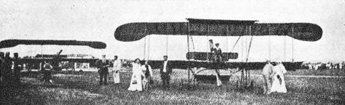
The Vindobona II aeroplanes. The Autobiplan Warchaiowski System Type I, with Karol Warchalowski at the controls, in the foreground and, behind, the Type II, photographed in July 1910 during the Wiener-Neustadt Meeting. Note the single inner interplane struts and differently shaped wingtips of the Type I.

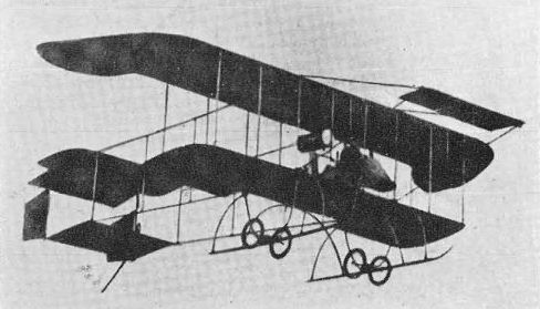
The Autobiplan Warchalowski System Type II in its early form and with the miniature basket-tyrpe nacelle attached.
Adolf Warchalowski and his improved, Gnome-powered Type II are greeted and decorated with a laurel wreath upon landing after the historic flight on the day of the Emperor of Austria's birthday over the centre of Vienna on 18 August, 1910. The Autoplan-Werke emblem can be seen on the front elevator and the Austrian national colours on the top wing.

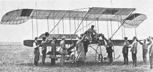
The Daimler-powered Warchalowski System Type III, photographed in front of the Autoplan-Werke factory after the establishment of a new national duration record on 27 December, 1910. Adolf Warchalowski and his passenger, Lieut Aztalos, are standing in the middle of the group.
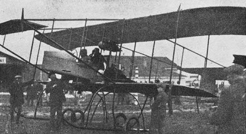
The Warchalowski Military Type I (Warchalowski System Type IV) with Daimler water-cooled inline engine, during its extremely successful flight trials early in the spring of 1911.
Autobiplan Warchalowski System Type VI to Type X. In the middle of August 1911, a new Warchalowski System biplane, the Type VI, emerged from the Autoplan factory, its debut marking the birth of a new generation of Warchalowski aircraft. The basic change from the previous practice was that in the new model the C.G. was moved forward and the tail surfaces no longer contributed to the lift.
It appears that the Autoplan-Werke undertook quantity production of this new basic airframe, and contemporary press reports indicate that at least nine or ten (and presumably more) examples, differing mainly in the various powerplants installed, were delivered in the last five months of 1911. At least three Type VIs, all powered by a 60 hp Daimler four-cylinder inline water-cooled engine, were completed, two in the middle of August and one in September. The first two Type Vis were followed about a week later by the single Type VII biplane, which featured a modified nacelle equipped with more flight instruments together with some minor refinements and was fitted with a more powerful 80 hp Anzani six-cylinder radial air-cooled engine. In September and October at least three Type VIIIs, an improved edition of the Type VII adapted for a 70 hp Gnome seven-cylinder rotary engine, left the factory. At the beginning of October a new development, the Type IX, with a slightly revised nacelle, a new 85 hp Werner & Pfleiderer Hieronimus four-cylinder inline water-cooled engine and increased load-carrying capabilities, made its public appearance.
The Type X, a further development of the previous model, designed to make the maximum use of the potentialities of the new Hieronimus engine and lift even heavier loads, began trials in the latter half of December 1911. On the 21st of that month this machine, with Josef Sablatnig in the cockpit, made six flights, one of them with a passenger and an additional ballast load (bags of sand) of 280 kg (617 lb) on board. Later, the same pilot accomplished a few short flights with five passengers on board, one sitting behind him and two on each side of the nacelle on the wings. The longest flight with five passengers lasted about 15 min. The empty and maximum loaded weights of the Type X were in the region of 500 kg (1,102 lb) and 950 kg (2,094 lb) respectively.
The new Warchalowski System Autobiplans figured prominently in all major Austrian aviation events of the latter part of 1911 and enhanced the reputation of their designer. One Type VI was used by Josef Sablatnig for his attempt to win the Niederosterreichische Rundflug (Tour of Lower Austria). On 17 August, flying with Hutter in the passenger seat, Sablatnig made a test and training flight from Wiener-Neustadt to Neunkirchen, achieving an average speed of 106 km/h (65.8 mph). Two days later the same crew took-off at dawn on the real prize flight. However, a strong wind caused a shortage of fuel and a forced landing between stages which ended in a crash and very serious damage to the machine. Undeterred, Sablatnig renewed his attempt at dawn on 24 August on the brand-new and not yet properly tested Type VII biplane equipped with an Anzani radial. This time luck was on his side. Following the specified 345 km (214 mile) route in stages in accordance with the contest rules, he landed at Wiener-Neustadt 36 hr 41 min after take-off, the shortest time achieved by any competitor, and won the close-fought and highest-ever Austrian money prize of 20,000 Korons. The average flying speed was over 110 km/h (68.3 mph).
While Sablatnig was fighting for victory in the Rundflug, Adolf Warchalowski was in the news because of his exploits as a reconnaissance pilot during large-scale Austrian army manoeuvres. On 16 August his new Type VI made its proving flights and three days later the machine and its field hangar arrived at Virovitica and were established at a base close to the HQ of a cavalry group with which Warchalowski was to co-operate. The morning of 22 August marked the first use of an aeroplane for operational purposes in Austria. Warchalowski spotted the 'hostile' cavalry formations and returned with a complete report of their dispositions and plans. Two more reconnaissance flights on the same day brought further important information and permitted his own force to take counter-action. Two reconnaissance missions were flown the next day with similar results. Two other aircraft took part in the same exercise, but none of the crews matched the skill of Warchalowski, whose convincing demonstration of the military potential of air reconnaissance made a great impression. Flying as a civil pilot, Adolf was engaged on two more series of military manoeuvres, one at the beginning of September in the Komorn area and another in November.
Four Autobiplans, two Daimler-powered Type VIs and two Gnome-powered Type VIIIs, with three pilots, Adolf and Karol Warchalowski and Josef Sablatnig, were entered for the First Austrian Aviation Week championships held in the first week of October 1911. In the opening phase of this event Sablatnig's Type VI caught fire in flight, but, although the machine was completely burned out after a forced landing, the pilot and his passenger escaped unharmed.
In the contest the Warchalowski biplanes proved once again their superiority over most other competitors, winning an impressive number of prizes and several leading places. Adolf, on the Type VI, won the first race from Wiener-Neustadt to Neunkirchen and back (32 km = 19.9 miles in 24 min 36 sec) and was placed second in the final race classification. Karol, on the Type VIII, received two days' flight prizes and gained the third and fourth places in the height competition. Sablatnig, on another Type VIII, took three days' prizes (for the opening flight, endurance and height) and second place in the overall height classification (933 m = 3,061 ft absolute height).
On 7 October, in the closing stages of the championships, the new Type IX, powered by the equally new and untried Hieronimus engine, joined the Autobiplan team. Taken by Sablatnig for a race, the aeroplane suffered engine trouble and the flight had to be interrupted. Early the next morning, Sunday, 8 October. Adolf Warchalowski took-off on the Type IX for an attempt on the world endurance record established by Fourny some five weeks earlier, but he was forced to land after 3 hr 17 min 20 sec because of mechanical trouble, his consolation being the day's endurance prize.
On 30 October, 1911, Adolf Warchalowski flying the Hieronimus-powered Type IX made a record-breaking flight from Wiener-Neustadt, with three passengers on board, which lasted 45 min 46 sec, exceeding by a handsome margin the previous achievement by Busson (31 min 23 sec), and this was soon homologated as the new world endurance record with three passengers. During the flight Hutter sat behind the pilot in the passenger seat and two mechanics lay on the wings, one on each side of the nacelle, the total load carried (people and fuel) amounting to 310 kg (683 lb) and the total loaded weight of the aircraft being some 800 kg (1,764 lb).
Earlier, on 21 October, on the occasion of the marriage of Archduke Karl Franz Josef to Princess Zita of Bourbon-Parma, Adolf flew from Wiener-Neustadt to Schwarzau Castle, where the wedding took place, with a silver sculpture representing a figure carrying a Warchalowski Autobiplan in flight, which he presented to the bride as a wedding gift. By the end of 1911 Adolf Warchalowski was counted among the most outstanding and experienced pilots in Austria, having to his credit a combined total (for 1910 and 1911) of 550 flights, including 196 with passengers, in over 125 flying hours.
At least two Type IXs were completed, and these aeroplanes and one of two earlier Warchalowski models competed in some aviation events in 1912, including the great International Aviation Week championships in the last week of June, in which 43 contestants from ten countries took part, but they did not achieve major successes. Several of the Warchalowski second-generation types were used for a considerable time for the training of military and civil pilots.
Construction: The Autobiplan Warchalowski System Type VI to Type X were two-seat open-frame unstaggered single-bay biplanes, which basically followed structural methods similar to those employed on the previously described Warchalowski types. Although these aeroplanes retained a generally similar layout, their powerplants, fuel and oil tanks and other heavy parts and installations were moved forward to bring the C.G. within the wings, and a number of aerodynamic and structural improvements were introduced. The wings, featuring the characteristic Warchalowski tips, were single-bay structures of unequal span (with the lower wing spanning 8.8 m = 28 ft 10 1/2 in) and their gross area was 42 sq m (452.1 sq ft). The tail unit, which fulfilled the normal function of a stabilizing and control device (no longer contributing to the lift), was of monoplane type, with the tailplane attached to the rear ends of the fuselage upper longerons, and a central single rudder below the tailplane. The overall span quoted for the Type IX was 12 m (39 ft 4 3/4 in) and the length, estimated from photographs, was about 13 m (42 ft 7 3/4 in). It appears that all the Warchalowski aircraft of the new series (Type VI to X) had very similar overall dimensions. Empty and loaded weights of the Type VI, VII and VIII were 400-450 kg (882-992 lb) and 650-700 kg (1,433-1,543 lb). Performance included a maximum speed of 110-120 km/h (68.3-74.5 mph) and maximum normal endurance of 3 hr (for aircraft flown with one passenger).

The Warchalowski System Type VII with 80 hp Anzani six-cylinder radial engine flown by Josef Sablatnig in his successful bid to win the Niederosterreichische Rundflug.
The Hieronimus-powered Type IX before taking off for its record-breaking flight with three passengers on board and Adolf Warchalowski in the pilot's seat, on 30 October, 1911.
Autobiplan Warchalowski System Type XI. In the autumn of 1911 Adolf Warchalowski conceived a design for a seaplane to a requirement of the Austrian Naval Command. Construction of the single example of this floatplane (Type XI) began in November of the same year and the machine was finished just in time to be shown at the IFA (International Aviation Exhibition), which was staged in Vienna from 18 May to 23 June, 1912. Displayed in the centre of the exhibition hall on a specially provided pool, the floatplane stole the show, and another Warchalowski Autobiplan, the Hieronimus-powered military biplane, presumably Type IX, displayed with it, also received a fair share of attention.
The Type XI Hew for the first time on 25 July, 1912, from Wiener-Neustadt airfield with Adolf Warchalowski at the controls, its floats being provided with wheels for the flight trials, and two days later it made its first flights with passengers. On 7 August, in the course of the official acceptance trials, the Type XI took-off with the maximum specified load of 260 kg (573 lb), comprising a pilot, observer, fuel and sand ballast, and stayed in the air for 30 min at a height of 200 m (656 ft). On 10 August the machine, carrying the same load, took-off in less than 150 m (492 ft), half of the specified distance, and during the speed test recorded an average speed of 70 km/h (43.5 mph). Later the same day the aircraft made a duration flight of 1 hr 3 min during which it climbed to 700 m (2,296 ft). After completing all its trials with flying colours the Type XI was delivered to the naval base at Pola, becoming the second seaplane to go into service with the Austrian Navy.
The Type XI was the last aircraft to be developed by Adolf Warchalowski. Early in 1912 the Austrian authorities decided to convert Wiener-Neustadt aerodrome into a military aviation centre after which civilians were to be excluded. On 21 March, 1912, Adolf Warchalowski, who, as a Pole, was presumably regarded as a potential security risk, announced his intention of leaving the Autoplan-Werke after completion of the Type XI seaplane and of establishing a factory for agricultural machinery in partnership with his brother Jozef. Several weeks earlier the design work on a new biplane, begun to meet an Austrian War Office specification for a 'Normal-type' (Standard-type) military aircraft, which had been issued in December 1911, passed from Adolf Warchalowski to Josef Sablatnig (this machine, known as the Sablatnig Military Biplane, making its first flight on 1 May, 1912). Autoplan-Werke, which had to vacate their Wiener-Neustadt premises, intended to move to a civil airfield, but this plan was eventually abandoned and in September 1912 the firm merged with Etrich and Lohner to form one large concern, which began the development and quantity production of military aircraft to Austrian Government contracts.
Construction: The Autobiplan Warchalowski System Type XI was a two-seat open-frame unequal-span twin-float naval biplane of composite construction. The wings, fabric-covered two-spar wooden structures with a total gross area of 48 sq m (516.7 sq ft), comprised a wide centre section and single-bay outer sections, the outer panels of the lower wing being set at a pronounced dihedral angle. The crew nacelle, housing an engine in front and side-by-side seats for a pilot and observer behind, was attached under the lower wing in order to bring the C.G. as close to the waterline as possible. The open-type rear fuselage frame carried the tail unit, which was of monoplane type and consisted of a single rudder, tailplane, and elevator. The float gear comprised two main flat-bottomed wooden floats, which were carried on a metal-tube framework, and a small single float under the tail. Power was supplied by one 85-90 hp Werner & Pfleiderer Hieronimus four-cylinder inline water-cooled engine, installed in the nose of the nacelle and offset to starboard, which drove a two-blade pusher airscrew through a system of transmission shafts and gears. Overall dimensions included a span of 15 m (49 ft 2 3/4 in) and a length of 10 m (32 ft 9 3/4 in). Empty and maximum loaded weights were 650 kg (1,433 lb) and 910 kg (2,006 lb).
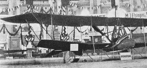
The Warchalowski System Type XI twin-float seaplane for the Austrian Navy, as shown at the IFA exhibition in Vienna in 1912.
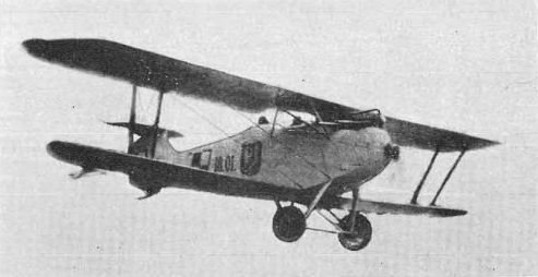
The C.W.L.-built development of the Hannover-Roland CL II, the Daimler-powered Slowik biplane, during its fatal flight on 23 August, 1919.
Torpedo Monoplane
The second of the Plage designs, which he evolved jointly with the German engineer Court, and acclaimed by the contemporary German press as one of the most interesting and advanced aircraft to appear in Germany in 1911, was called the Torpedo Monoplane because of its exceptionally clean shape. It was constructed in the Max Leuchner Kuhlsteins Wagenbau catbody factory and completed in October 1911.
The machine, a two-seater intended for military purposes as well as for cross-country and high-performance flying, represented a new concept in aerodynamic and structural design. With the greatest emphasis laid upon the reduction of drag and upon protection of the crew in case of a crash landing, careful thought was given to every small detail. On the score of elegance and beauty of line the resulting aircraft had no equal among its contemporaries. The German army authorities expressed considerable interest in the machine, which at their request was delivered to Doberitz for military trials. Unfortunately, nothing further was heard of the Torpedo Monoplane after the very favourable initial press reports.
Construction: The Torpedo Monoplane was a two-seat military or high-performance machine of wooden construction. The wing, of cambered aerofoil section and with an area of 26 sq m (279.9 sq ft), was attached to the fuselage upper longerons and braced with steel wires to a steel-tube pyramid on top of the fuselage and below to the undercarriage framework. The wing was a divided multi-spar structure, both the spars and the ribs being made of ash, and was covered with fabric which was doped with glue. Each wing panel, with a rounded tip and slightly increased chord at the root, had a span of 5.5 m (18 ft 0 3/4 in) and a basic chord of 2.6 m (8 ft 6 3/4 in), and was set at a pronounced dihedral angle. Each wing was provided with a window between the spars at the root to permit the pilot to see the ground during landing. The wing could be completely detached in 10-12 min.
The fuselage, a streamlined structure of ash, was built-up of four longerons and a number of circular frames, its rear section tapering to a fine point. Its forward section, up to the radiators, was covered with duralumin panels, which were hinged to permit easy inspection of the engine and its installations. Aft of the radiators the fuselage was covered with fabric. The raised pilot's seat was situated in the centre and the passenger's cockpit under the wing-bracing pyramid, some distance in front, at the C.G. The wing warping and the elevator were operated by a steering column with a steering wheel, and the rudders by a rudder bar. Dual controls could be fitted. The tail unit, of cruciform configuration, comprised two identical fin and rudder surfaces above and below which were attached to a vertical steel tube filled with solid wood for strength, a divided tailplane and a one-piece elevator with an area of 4.5 sq m (484 sq ft). All the tail surfaces could be quickly detached for transport. The landing gear, of very simple and neat divided design, incorporated two mainwheels and a tailskid.
Power was supplied by a 70 hp Argus four-cylinder inline water-cooled engine, carried on a steel-tube mounting and driving a two-blade tractor airscrew with a diameter of 2.6 m (8 ft 6 3/4 in). The airscrew was provided with a large-diameter spinner which formed the aerodynamic extension of the fuselage nose contour. The two Windhoff aluminium radiators, weighing with water a mere 16 kg (35 lb), were specially designed for the machine and inset into the fuselage sides (under the wing) so as to provide the maximum cooling area with the minimum of drag. A very advanced fuel system incorporated two fuel tanks with a total capacity of 110 litres (24.1 Imp gal), one in front of the passenger seat on top of the fuselage and the other inside between the pilot's and passengers seats, and a small 8 litre (1.7 Imp gal) reserve tank which gave the pilot time to look for a suitable landing ground when the fuel gauge showed 'tanks empty'. The Torpedo Monoplane had an overall span of 11.6 m (38 ft 0 3/4 in), a length of 9.7 m (31 ft 10 in) and a wing area of 29 sq m (312.15 sq ft). Its estimated maximum speed was 130 km h (80.7 mph) and range 500 km (311 miles). No other data are available.
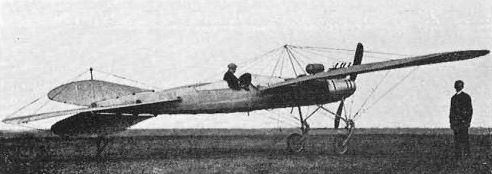
The exceptionally clean and advanced Argus-powered Torpedo Monoplane in October 1911.

Another view of the Torpedo Monoplane, with Plage and Court standing in front.
Kuhlstein Torpedo monoplane with 70hp Argus. [1911]
Kuhlstein Torpedo monoplane with 70hp Argus. [1911]
Babinski's Gliders
Zbigniew Babinski was a close friend of Wladyslaw Zalewski. They both lived in Milanowek near Warsaw and shared an active interest in aeronautics. Following his friend's example. Babinski built a man-carrying glider in the first half of 1912. The design, a huge boxkite-type biplane, was evolved to the ideas and instructions contained in the book How to Build a Glider by Michal Krol.
The glider was first tested in June 1912, three friends, Babinski, Zalewski and Woyna, being involved in this exercise. Zalewski recollected: 'We set off at dawn for the small hills in the meadows on the outskirts of Grzedow, which lay between the Krolewska highway and the railway line. Despite its huge size, the machine was very light and the three of us carried it tail up without too much effort. We made our gliding attempts in a very light westerly wind of only about 2 m/sec (4.4 mph). The lifting capability of the design was very great; when two of us holding the tips of the bottom wing let them go after a brief run and the third lifted his feet up, the aircraft made a pleasant glide at an even height above the very gentle slope of the hill, covering some 30 to 40 m (98 to 131 ft) at a stretch. Babinski glued in new sheets of tissue-paper, repairing the pieces torn during landings and each of us took his turn at making glides. After about two hours I and Woyna had to leave, and Babinski stayed behind alone with the aircraft.'
With the help of a few shepherd boys, Babinski continued to fly his glider as a kite, without a pilot, launching it higher and higher. During these operations the aircraft, which rose to some 40 m (131 ft), was suddenly caught in a strong wind and one of the wires by which it was being pulled slipped loose from the hands of the boy holding it. The glider lost its equilibrium and was completely wrecked on hitting the ground.
The glider was an equal-span biplane constructed of wood and trussed with steel wires. The airframe consisted of two-bay wings, which were covered on the bottom surfaces with gauze pasted over with tissue-paper, a simple open frame fuselage and a cellular tail bay. A cambered aerofoil section was employed and the lifting surface area exceeded 40 sq m (430.5 sq ft). The pilot, with his armpits supported by special fittings, hung in the uncovered centre section of the lower wing and controlled the balance by movements of his body. No other data are available.
In 1913 Babinski built a smaller glider (less than half the lineal size of the previous machine), which, whilst employing a flat, instead of cambered, aerofoil section, was in all other respects exactly similar to the earlier design. However, with the flat wing and small supporting surface, this aircraft was far less stable and more difficult to fly. In spite of this the designer and his friends, including Zalewski, carried out several short glides on it, 14-year-old Kazimierz Wasiutynski, small and light, making by far the largest number of successful flights. The overall span of this second glider was 6.8 m (22 ft 4 in) and its empty weight was 25 kg (55 lb).
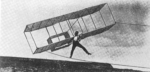
Babinski's second glider at the moment of launching, with its pilot desperately trying to maintain balance.
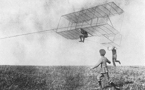
Kazimierz Wasititynski on the second Babinski glider during a perfect launch sometime in 1913.
Barters Gliders
From boyhood, Ryszard Bartel was absorbed with the problems of flight. Passionately studying all the available literature on the subject, he constructed his first flying model in 1909. This was an ornithopter-type machine powered by a clock mechanism, with wings like Venetian blinds which shut during the downward beat. Later he built larger wings, which were constructed on the same principle and had a span of 1.5 m (4 ft 11 1/2 in). They were hinged to a light frame carried on the shoulders and strapped to the body. Bartel tried a few jumps with this device.
During the later period he evolved a number of model aircraft, some of which were powered by ingenious compressed-air engines of his own design. The problems of longitudinal and lateral stability attracted his particular attention and by conducting tests with his models and observing their behavior he gained a considerable knowledge of the principles of mechanical flight.
In 1911, inspired by descriptions in aviation publications of Tanski's works and experiments, Bartel designed a tail-first man-carrying glider, which resembled in general layout some of Tanski's projects. The machine, which was to be operated in the same manner as the Lotnia (its pilot had to hold it in his hands and run against the wind), proved too heavy for the then only 14-year-old boy to handle. Later in 1911 Bartel extensively revised the design. The new glider, while retaining the wings and tail unit of its predecessor, was of conventional configuration and embodied a completely new, very light and simple fuselage frame, built up of a minimum amount of wood and well trussed by steel wires. However, this frame was too fragile and broke during the first attempt at flight. The young designer then devised an improved reinforced frame, and the glider in this form was first tested flying as a kite and carrying a small boy 1-2 ft above the ground.
Bartel subsequently made a number of short jumps with the glider from the hill slopes of the Renard quarry at Sielec near Sosnowiec in Silesia. These usually ended with one wingtip coming in contact with the ground, but without damage to the craft. The very short duration of each jump did not allow the pilot to make use of the controls with which the aircraft was provided. The experiments were interrupted when the Bartel family moved from Silesia to central Poland. In spite of its great simplicity, the Bartel glider was an ingenious and purposeful design. During its development and improvement the young constructor was advised by his older friend Aleksander Stephan, then a student at the Lwow Technical University.
The Bartel glider was a very simple open-frame monoplane of wooden construction. The whole airframe was glued and nailed together and all fixtures were made of thick wire. The single-surfaced wing, with an area of 14 sq m (150.7 sq ft) and chord of 2 m (6 ft 7 in), was covered with fabric impregnated with starch, the fabric being nailed to the framework. The fuselage consisted of two longerons trussed with steel wires and carried a movable tail unit, which comprised a pivoting one-piece horizontal surface with a rudder on top. The seat was a canvas cushion filled with straw, and hung under the wing on ropes. The control stick above the pilot's seat provided means of control, devised to follow the automatic reflexes of the pilot. The fore and aft movements of the stick controlled longitudinal stability in the manner opposite to the conventional system (forward for nose up and aft for nose down attitude), and sideways movements, which operated the rudder, combined with the natural movements of the pilot's body, controlled the lateral and directional stability. According to the designer's data, the span of the glider was 7 m (22 ft 11 3/4 in) and the length 4.75 m (15 ft 7 in).
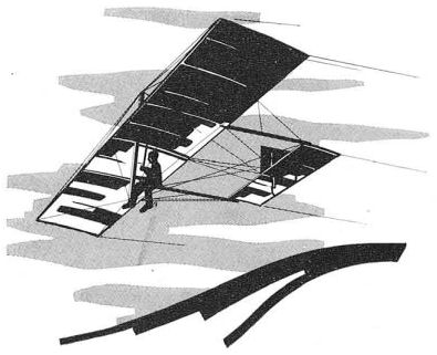
The Bartel open-frame glider.
Chlebowski Brothers' Triplane
The brothers Wladyslaw, Henryk and Stefan Chlebowski were counted among the best-known and most active aviation enthusiasts and proponents working in Lodz. In the years 1909-10 they evolved a study for a triplane and in 1910 constructed a detailed quarter-scale flying model of the proposed aircraft.
The model, a structure of bamboo covered with fabric, was powered by an unspecified French-made two-cylinder vee engine driving a tractor airscrew. The output of this engine was given in the contemporary Polish press as 10 hp, but this could hardly be correct and perhaps the figure of 2 hp would be more realistic. On 30 August, 1910, the model made a successful free flight. The machine, which was equipped with a special device of the Chlebowskis' design to maintain lateral stability, climbed to some 10 m (33 ft) and stayed in the air for three minutes, making large circles. Encouraged by this success, the brothers intended to begin immediately the construction of the full-size aircraft, but financial difficulties put an end to this plan. In any case a study of photographs of the model reveals certain deficiencies in the design and lack of expertise on the part of the designers (e.g. incorrect positioning of the struts supporting the uppermost wing) and it seems rather doubtful that their full-size triplane would have been structurally sound.
Some Polish historians have confused the Chlebowski brothers' triplane model with the Montgolfier monoplane, which the brothers bought on an instalment basis towards the end of 1910 or early in 1911. This monoplane, a development of Santos-Dumont's Demoiselle, was constructed in France early in 1910 by an Austrian, Lieut Heinrich Bier, who named it the Montgolfier and took it with him to Wiener-Neustadt. The Montgolfier monoplane was shown by the Chlebowski brothers together with their triplane model at the Aviation Exhibition in Helenow Hall in Lodz, which was open for two weeks in the second half of March 1911, As the brothers were unable to keep up the payments, the Montgolfier monoplane was sequestrated by a court order in August 1911.
The general configuration of the Chlebowski brothers' proposed triplane is apparent from the photograph of the model. No details about the project are available.
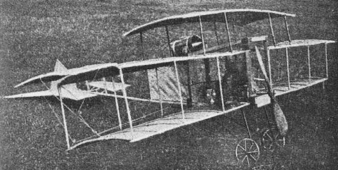
Flying model of the Chlebowski brothers' triplane. The structurally unsound positioning of the top interplane struts is apparent from this picture.
Glider of the Chrzanowski Secondary School Students
Students of the Chrzanowski Secondary School in Warsaw, inspired by the first flight attempts of Legagneux in their city, formed an 'Aviation Circle' in the latter part of 1909 and began to construct flying models. Its most active members, Waclaw Jedrzejewicz, Leonard Mozdzehski, Waclaw Niwinski and Lech Niemojewski (who voluntarily helped Zbieranski and Cywinski to built their biplane in the Aviata hangar) evolved a rudimentary man-carrying biplane glider, the design of which was based upon Michal Krol's book How to Build a Glider.
The glider was constructed in Jeziorna near Warsaw, in a shed belonging to a paper factory which was put at the disposal of young enthusiasts free of charge, and tested from the slopes of the small hills in Klarysew during the 1912 summer holidays. The craft, which made a number of steady glides, appeared to be one of the most successful devices in its class in Poland in this early era. Jedrzejewicz, who was the lightest of the four students, covered on occasions distances of 200-300 m (656-984 ft) at a stretch, gliding sometimes to a height of some 20 m (65 ft). Unfortunately, during the last of these flights, a bamboo rest supporting the pilot snapped, the glider lost stability and crashed. Jedrzejewicz received cuts and heavy bruises and the aircraft was never rebuilt.
Construction: The glider was an equal-span biplane constructed of bamboo and trussed with wires. The wings and cellular-type tail bay were of single-surfaced type, a cambered aerofoil section being employed. A single, open vertical frame formed the fuselage. The pilot hung in the uncovered centre section of the lower wing and controlled the balance by swinging his suspended body. The craft had a span of 7.6 m (24 ft 11 1/2 in) and its empty weight was 25 kg (55 lb).
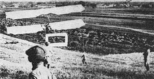
The glider of the Chrzanowski Secondary School students during one of its successful flights in Klarysew in the summer of 1912.
Glowinski's Monoplane
In May 1911, the Lwow press informed its readers about a successful flying demonstration of Glowinski's monoplane. The machine, designed by Bronislaw Glowinski in 1910 and constructed and flown by him in Tarnopol, should therefore be regarded as the first Polish aeroplane to achieve a controlled and sustained flight in Poland.
Modelled to a certain extent on the lines of Bleriot Type No. XI, but embodying several original and imaginative features, the machine made a number of short flights over an improvised airfield near Tarnopol in the late spring and summer of 1911. Unfortunately, the designer was unable to obtain the required materials and was forced to use heavier substitutes. This increased the weight of the airframe beyond the anticipated figure, and a weary Anzani engine, overhauled and modified by Glowinski, did not provide the desired power and reliability. As a result the monoplane was rather underpowered and this, combined with frequent breakdowns on the part of the capricious powerplant, severely limited its capabilities and performance and prevented Glowinski from attempting any flights beyond the area of the improvised landing field. His ambition to undertake prize flights in Lwow was never realized.
The condition of the engine deteriorated quickly and some of the parts soon became worn beyond repair. The designer could not afford another engine, and, as the expected help from ZASPL never materialized, he dismantled his machine towards the end of 1911 and had to abandon flying altogether. Later, for a time, he attended the Lwow Technical University, and the forward section of his aircraft was displayed at the Second Aviation Exhibition in Lwow, which opened on 16 February, 1913. Unable to overcome financial difficulties and disenchanted with the unfulfilled promises of support from aviation organizations, he eventually left Poland before the 1914-18 War to work on the construction of railway lines in Asia, but came back after the end of hostilities. Parts of his monoplane, stored in various places, survived until the 1939-45 War.
Construction: Giowiriski's aircraft was a single-seat braced monoplane of composite construction. The wing, a two-spar wooden structure of double-surfaced type covered with fabric, was built in two sections. Each wing panel, carried immediately above the main fuselage frame on an inverted twin-V cabane, was attached to the base of the cabane and braced to its top by wires, and to a low cabane under the second fuselage frame and the landing-gear framework. To maintain lateral stability wing warping was employed. The fuselage, an open brass-welded metal-tube structure trussed by wires, was of rectangular section forward and triangular section aft, terminating in a vertical knife-edge at the tail. The landing-gear frame and all supporting cabanes were built of metal tubes integral with the fuselage. The pilot's seat was situated at the rear of the rectangular fuselage section. The control system consisted of a conventional control stick and rudder bar, the controls being by cable, except for the elevator system which was by push-rod to the back of the rectangular fuselage section and thence by cable. The tail unit, a wooden structure covered with fabric, consisted of a rudder, a tailplane and Bleriot-type full-chord elevators, the tailplane being wire-braced to the fuselage top longerons and supported by a cabane under the rear end of the fuselage. The landing gear, of neat design, comprised two outwardly-splayed side Ns, supported by a pair of struts and coupled by two transverse tubes. A pair of long wooden skids was attached to this framework. A cross-axle, carrying two wheels, was attached by rubber shock-absorber cords to the skids. The tailwheel fork was provided with a spring shock-absorber. Power was supplied by the 25 hp Anzani three-cylinder air-cooled semi-radial engine directly driving a two-blade tractor airscrew. The fuel tank was attached to the wing-carrying cabane. The monoplane had a span of 10.2 m (33 ft 6 in). No other data are available.
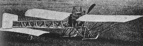
Glowiriski's monoplane, which in May 1911 was the first Polish aircraft to achieve a sustained flight in Poland.
Gold's Monoplane
The third full-size aircraft to appear at the First Aviation Exhibition in Lwow, which opened on 1 September, 1910, was the monoplane designed by Willibald Gold. The machine, of very light and simple construction, was built by the Witold Tranda Mechanical Workshop in Lwow in the summer of 1910. However, a close study of the only available photograph reveals certain design errors and nothing is known about any flight attempts or the subsequent fate of the aircraft.
Construction: Gold's aircraft was a light single-seat wire-braced high-wing monoplane. The machine embodied a single-surfaced fabric-covered wing with an area of 13.5 sq m (145.3 sq ft) and an open fuselage frame with a general configuration reminiscent of Weber's biplane. The wing appeared to be provided with pivoting wingtips for lateral stability control. The design seemed to be of the lifting-tail variety and featured a forward elevator which was carried on outriggers in front of the wing. Power was to be supplied by a 15 hp engine, of unspecified type and make, driving a pusher airscrew. The overall span was 6.75 m (22 ft 2 in) and length 8 m (26 ft 3 1/4 in). Net weight of the airframe less engine was 50 kg (110 lb). No other details are available.
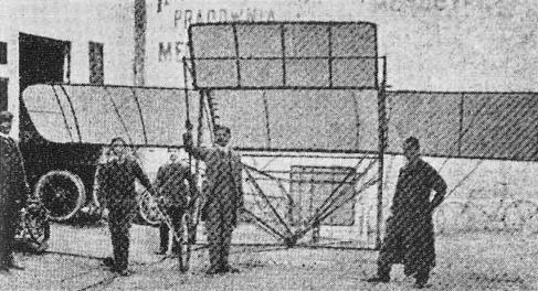
The engine-less Gold ultra-light monoplane in front of the Witold Tranda Mechanical Workshop in Lwow in 1910.
Joachimczyk's Aircraft
Alfred Marceli Joachimczyk, a Polish engineer working in Berlin, evolved an aircraft of his own design in 1910. The machine, completed in the early spring of 1911, featured three sets of wings in tandem, a monoplane wing forward, the main multi-bay cellular biplane wing in the centre and another monoplane wing at the rear, and was propelled by two sets of contra-rotating pusher airscrews. These were driven by a water-cooled engine installed within the fuselage. The general configuration of the aircraft is apparent from the photograph, but details regarding its design and dimensions are lacking. As far as is known the aeroplane was not successful.
Alfred Marceli Joachimczyk, a Polish engineer working in Berlin, evolved an aircraft of his own design in 1910. The machine, completed in the early spring of 1911, featured three sets of wings in tandem, a monoplane wing forward, the main multi-bay cellular biplane wing in the centre and another monoplane wing at the rear, and was propelled by two sets of contra-rotating pusher airscrews. These were driven by a water-cooled engine installed within the fuselage. The general configuration of the aircraft is apparent from the photograph, but details regarding its design and dimensions are lacking. As far as is known the aeroplane was not successful.
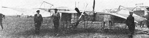
One of the most complicated and ungainly aircraft to be evolved by a Polish designer, the unsuccessful Joachimczyk machine with two sets of pusher contra-rotating airscrews, photographed in Berlin in the spring of 1911.
Kolousek's Biplane
Another Krakow designer, Stanislaw Kolousek, (whose name was later frequently mis-spelled as Koluski), evolved a detailed study for a tractor biplane and early in 1910 built an elaborate quarter-scale flying model of the proposed aircraft. The model, true in every detail, was powered by a single-cylinder petrol engine of unspecified make and output. The powerplant system, which incorporated a battery, and the fuel installation were also fully representative of the full-size project.
During several flight attempts in the early spring of 1910, the model, carrying an appropriate load, achieved encouraging results. After a ground run of 20-30 m (65-98 ft), the aircraft climbed to a height of 3-4 m (10-13 ft) and flew over a distance of 50-60 m (164-197 ft), until it ran out of fuel, and then landed correctly. The model was displayed in Krakow in May 1910, and later appeared at the First Aviation Exhibition in Lwow, which opened on 1 September that year. The full-size machine was never built.
Kolousek's proposed aircraft was a single-seat unequal-span two-bay biplane of wooden construction. The machine featured an open-frame rectangular-section fuselage, a biplane-type tail unit, and conventional landing gear consisting of a cross-axle with two mainwheels, two side Vs and a tailwheel. No other details are available.
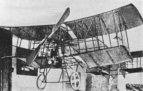
Kolousek's biplane as exhibited in Krakow in May 1910.
Kozlowski's Biplane
Stefan Kozlowski, a young Polish automobile enthusiast in his early twenties, became increasingly interested in aeronautics and in the autumn of 1909 went to Germany to study aircraft engineering at the Fachschule fur Flugtechnik in Zahlbach and to learn to fly. While at this school, Kozlowski, consulting the Czech designer Skopik, evolved a detailed study for a tractor biplane, which, except for the powerplant arrangement reminiscent of the Wright system and the wing structure resembling Bleriot practice, was original in concept and layout.
Kozlowski returned to Warsaw on 25 January, 1910, and, with financial backing from Fraczkowski, at the beginning of the following month began construction of his biplane in the Wilczynski timber yard in Czerniakowska Street. With four craftsmen to help him, Kozlowski worked very quickly. In the middle of March the designer took delivery of an Anzani engine, airscrews, rubber-proofed fabric, wheels, tyres and other accessories from abroad, and by the end of that month all wooden assemblies and metal fixtures were ready. At the same time work began on a hangar in the nearby Siekierki meadows, and the airframe was moved there for final assembly early in April.
On 27 April, 1910, initial engine runs were made, and next day came the first taxi-ing run with Kozlowski in the pilot's seat but this revealed some shortcomings in the alignment of the wings. The fault was rectified and ground trials recommenced a few days later. Early in May. during the first take-off attempt, one of the transmission chains broke and the machine went back to the hangar for modifications, which included the replacement of the chains by specially impregnated hemp ropes, revision of the transmission system and engine mounting, exchange of the original pine interplane struts for stronger glued ash struts and improvement of the wing bracing in order to ensure better rigidity of the structure.
The improved machine, free from the vibration experienced earlier, resumed ground runs at the end of May, and early in June made its first short jump. During some 30 take-off attempts that followed, Kozlowski made six brief flights in a straight line, and according to his own statement these covered distances in excess of 30 m (98 1/2 ft) at a height of some 3 m (9.8 ft). However, the aircraft appeared to be tail-heavy and on occasions its tailwheel refused to leave the ground. Kozlowski intended to redesign the tail and add a tailplane and fin, but as his aircraft was to appear at the Aviation Day exhibition on Mokotow aerodrome in Warsaw on 26 June, he postponed this work until later.
Before transporting his biplane to Mokotow, the designer decided to make one more take-off attempt. This proved disastrous. The machine hit a dip in the ground and was severely damaged, while its pilot received cuts and bruises. This accident led to a row with his sponsors, who had hoped to profit by the aircraft's appearance at the exhibition and other future events and refused to provide funds for repairs. In the early autumn of 1910 Kozlowski advertised his biplane for sale, and financial difficulties forced him to abandon further aviation activities.
Despite its shortcomings and lack of satisfactory controllability, Kozlowski's biplane has a place of honour in the history of Polish design endeavour as the first indigenous aircraft to leave the ground under its own power in Poland.
Construction: Kozlowski's aircraft was a single-seat equal-span unstaggered multi-bay biplane of wooden construction. The wings, with a total gross area of 40 sq m (430.5 sq ft), were frameworks of pine, which consisted of three spars and curved lattice ribs, and were covered on both surfaces with Continental rubber-proofed fabric. The undivided upper wing was carried above the fuselage on two struts and connected with the lower wing by five single interplane struts on either side. The lower wing was attached to the fuselage lower longerons. Hinged flaps, which were mounted halfway between the planes on the two outermost struts on each side, acted differentially to operate as ailerons or independently (on one side only) to provide directional control. The rectangular-section main fuselage frame consisted of four longerons and nine frames, the whole trussed by diagonal wires with strainers, and its rear portion was covered with fabric. The pilot's seat was situated at the front of the frame. The forward nacelle, which was attached to the fuselage lower longerons at the front end of the main fuselage frame, carried the fuel tank, flight controls and a steel-tube cross-axle with two mainwheels, the axle being provided with rubber-cord shock-absorbers. The tail, supported by a castoring tail-wheel, consisted of elevators only. Power was supplied by an Anzani six-cylinder W-type air-cooled engine, with a maximum output of 60 hp at 1,300 rpm, which was fitted at the head of the main fuselage frame, above and ahead of the pilot's seat. Two Chauviere tractor airscrews, with a diameter of 2 m (6 ft 7 in), were driven in opposite directions by hemp-rope gearing from the engine shaft, one rope being crossed in a similar manner to that adopted on the Wright biplane. Data regarding the biplane, as supplied to the author by the designer, included a span of 10 m (32 ft 9 3/4 in), a length of 9 m (29 ft 6 3/4 in) and a loaded weight of 300 kg (661 lb).

Kozlowsky's biplane of 1910. the first Polish powered aircraft to leave the ground in Poland.

Kozlowski's biplane at the Siekierki meadows in Warsaw, in the spring of 1910.
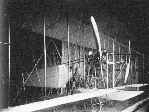
This night photo of the Kozlowski biplane with the designer at the controls shows to advantage a number of structural details.
Mono-biplan I
There can be little doubt that Dipl Ing Edmund Libanski was one of the most outstanding figures among the leading pioneers of aviation in Poland. He was the source of inspiration for the Lwow aeronautical activities in the pioneering era of the first years of the 20th century and his inexhaustible energy and drive turned that city into the most dynamic and enterprising aviation centre in Poland, overshadowing even Warsaw. With the publishing of his popular work, the Conquest of Atmosphere, (in 1905), and several articles and the delivery of numerous lectures, Libanski succeeded in bringing aviation to the notice of the public and stimulated Lwow Technical University with enthusiasm for flying. The increased general interest in aeronautics provided Libariski with the right climate for the creation of the first important aviation organization in Lwow, the Galicyjski Zwiazek Techniczno-Lotniczy 'Awiata' (Galician Aviation-Technique Association, the 'Awiata'), which was formed in the autumn of 1909 and had over 100 members. The 'Awiata', which became the Polish branch of the Austrian Aviation-Technique Association, was to operate over the entire region of the Galicia (the southeastern part of Poland then under Austrian occupation), and its broad aims included the propagation and support of all aviation undertakings and the preparation of a basis for the development of indigenous aircraft designs and industry. The 'Awiata' soon found an ardent ally in another, even bigger organization, the Zwiazek Awiatyczny Sluchaczow Politechniki we Lwowie (Aviation Association of Technical University Students in Lwow, which became known as ZASPL from the first letters of its full title). This came into being in November 1909, with the aim of promoting scientific research into the problems of aeronautics and aircraft construction and the creation of a faculty of aviation engineering at the University.
Organizing the aviation movement was not enough for Libanski; he undertook the development of his own aircraft. The design crystallized in 1909, and construction of the airframe began towards the end of that year. The machine, called by the designer the Mono-biplan I, was the first Polish composite design and the first to use steel tubes in the structure. Apparently inspired by the French Obre aeroplane of 1908, it employed an unusual configuration which embodied a main monoplane wing with a short-span supplementary wing on top.
The Mono-biplan I was built in the workshops of one of Lwow's largest locksmiths, and the airframe was ready in May 1910. The aircraft was equipped with an indigenous 48 hp four-cylinder air-cooled radial engine, constructed in Lwow, and drove, by means of chain transmission, a two-blade sheet-aluminium tractor airscrew with a diameter of 2.4 m (7 ft 10 1/2 in). Some parts of the engine were made by Zieleniewski Machine Factory in Krakow and only the cylinders were ordered from abroad, from the 'Kabel' Steelworks in Germany.
Libanski obtained permission to use the Lwow military exercise field and erected a hangar there, but the first flight attempt, undertaken by him about June 1910, ended in a mishap. During the take-off one of the cylinders exploded and the Mono-biplan I fell back on the ground, breaking both wheels. The front of the fuselage frame and the forward elevator were also damaged by the explosion, but the pilot escaped injury. Libanski then thought about fitting the machine with a Daimler or Korting engine, but came to the conclusion that the whole structure was rather fragile and not rigid enough, and he abandoned the Mono-biplan I completely. In the autumn of 1910 he began work on a vastly superior design, which later became known as the Jaskolka. His damaged Mono-biplan I, less its forward outrigger structure, was displayed at the First Aviation Exhibition in Lwow, which was open from 1 September until 15 October, 1910.
Construction: The Mono-biplan I was a single-seat multi-bay sesquiplane of the open-frame, lifting-tail variety. The airframe was a composite structure, all supporting areas being of wood, and the fuselage and landing gear framework, of welded steel tubing. The main wing, a divided two-spar structure with a chord of 2.5 m (8 ft 2 3/4 in), was attached to the upper fuselage framework at a slight dihedral angle and provided with pivoting wingtips, which controlled lateral stability. The straight one-piece supplementary wing, with a span of 4 m (13 ft 1 1/2 in) and chord of 2.5 m (8 ft 2 3/4 in), was carried above the main wing on four pairs of struts, the interplane gap being 1.6 m (5 ft 3 1/4 in). Both wings were covered with fabric on both surfaces. The combined gross area of all lifting surfaces (wing and tail) was given as 40 sq m (430.5 sq ft). The fuselage consisted of a rectangular-section forward part, which merged into a single vertical frame at the rear, the engine being mounted at the front of the fuselage and the pilot's seat situated at the rear of the rectangular section. All controls were operated by a steering wheel on a steering column. The tail unit, of biplane type, consisted of two similar horizontal surfaces, having a span of 3 m (9 ft 10 1/4 in) and chord of 1.5 m (4 ft 11 1/2 in), and a single rudder in between. The lower horizontal surface was fixed, while the top movable surface was linked with the forward elevator which was carried on outriggers in front of the wings and operated in conjunction with it to control longitudinal stability. The rear rudder was also linked with two movable vertical surfaces, one between the arms of each forward outrigger, which acted as supplementary rudders. The landing gear comprised a pair of mainwheels and a tailwheel. The whole airframe could be easily dismantled into large sections for transport. The overall span of the Mono-biplan 1 was 11 m (36 ft 1 1/4 in) and the overall length (estimated) 9.5 m (31 ft 2 1/4 in). The basic weight of the airframe less engine was 170 kg (375 lb). The loaded weight was 300-320 kg (661-705 lb) and wing loading 8 kg/sq m (1.6 lb/sq ft).
(Except for the overall length, which is estimated from photographs, all the above details and dimensions are taken from a comprehensive technical description of Libanski's aircraft in contemporary Austrian sources recently unearthed by the author).
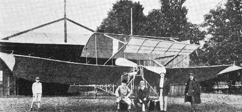
Libariski's damaged Mono-biplan 1 after its unsuccessful flight attempt in the middle of 1910, photographed in front of its hangar.
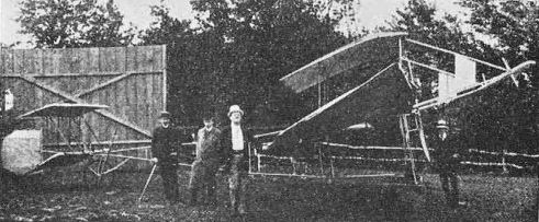
The Mono-biplan I damaged by the explosion of one of its cylinders. Note the missing front wheels and the pilot's seal, which can be seen under the trailing edge of the main wing.
Jaskolka (Swallow)
Edmund Libanski evolved a study for his second aircraft in the autumn of 1910. The machine, a two-seater believed to be initially designated the Mono-biplan II, was generally much more advanced and incorporated some startling features. Its main wing was swept back to 'increase speed and improve stability', and the machine was to operate either with or without its detachable short-span wing, which was carried on struts above the main wing and, in contrast to the Mono-biplan I, was provided with a movable flap to lower the speed of descent during landing. Because of its sweptback wing the aircraft was eventually named the Jaskolka (Swallow).
In December 1910, Libanski hired a disused hall from the Lwow town council and began construction of the Jaskolka with the help of Witold Rumbowicz. The airframe was completed in the late spring and slightly modified in the middle of 1911, and. presumably to ensure good airfield facilities and an experienced pilot, the designer offered the machine for tests to the Austrian military authorities. The Jaskolka was transported to Wiener-Neustadt airfield and assembled there in one of the military hangars under Libanski's supervision. In August 1911, the Jaskolka in its true monoplane form made the first successful, sustained, and controlled flights at Wiener-Neustadt, thus becoming the second machine (after the Glowihski monoplane) built in Poland to do so.
The fate of the aircraft is obscure and it has to be presumed that the supplementary top wing was never tested in the air. Although the Libanski flap gear was a very primitive device and was apparently never used, it was nevertheless a brilliant example of ingenuity and technical foresight on the part of its inventor and served as the inspiration for several Austrian designers. An essentially identical device was described by von Jirotka in the Osterreichische Flug-Zeitschrift of August 1911, in connection with proposals for his own aircraft (which generally resembled Libanski's Jaskolka), and a month later the same magazine printed photographs of the Jaskolka and recognized that the credit for the 'braking' flap should go to Edmund Libanski, who evolved it almost a year earlier. The efforts of other Austrian designers (including Karl Bombard, whose machine, also called the Mono-biplan, was test-flown at Wiener-Neustadt in January 1912, by Adolf Warchalowski) were also inspired by the Libanski-system wing concept, this being the first instance of an aircraft design evolved in Poland exercising an impact upon international aviation development.
It is obvious that the well-known Jaskolka formed a most formidable challenge to Zbieranski's claim to the title of the first and only successful Polish aircraft designer of that era. Zbieranski published the following statement on p. 101 of his book O narodzinach lotnictwa poiskiego (see Zbieranski and Cywinski biplane): 'The photograph depicting this aircraft, allegedly made by Ing Libanski and Rumbowicz in Wiener-Neustadt, was shown in Z. Dekler's "Aero-Office" in 1911 as the product of an Austrian T. Flieger from Vienna, anyway who with whom built this aeroplane is of secondary importance; the important thing is that the aircraft never found itself on Polish territory and cannot be included in Polish aviation. It had nothing to do with the birth of aviation in Poland.'
In the interest of historical truth it must be made clear that: 1) Tomasz Flegier (not Flieger) was always referred to as a Polish pilot, and as such gave a number of flight demonstrations in various foreign towns, including Riga (as evident from Swiat, 1911, No. 14, p. 13 and other press reports of the period); 2) there is not a shred of evidence to connect Tomasz Flegier with the design or building of the Jaskolka in any way (at that time he was in Russia); 3) not only Polish but also all contemporary Austrian documents and publications acknowledge without reservation that the sole designer and inventor of the Jaskolka and all its features was Edmund Libanski (Rumbowicz only helped him to build the machine in Lwow); 4) as already stated (on the evidence of Polish press reports of the period, e.g. Swiat, 1911, No. 35, p. 14) the Jaskolka was built in Lwow and taken to Wiener-Neustadt only for tests. In view of the above facts, Zbierariski's statement that the machine 'had nothing to do with the birth of aviation in Poland' is astonishing.
When Libanski went to Wiener-Neustadt with his Jaskolka, Witold Rumbowicz and Tomasz Flegier evolved jointly a design for their own monoplane project, which was derived from the Jaskolka. Construction of this machine, referred to as the Rumbowicz-Flegier system monoplane, was undertaken by the Warsaw 'Aero-Office' (the ownership of which passed at that time from Dekler to Stepowski and Rumbowicz) in the autumn of 1911. The airframe, built by Stepowski and Rumbowicz, was almost finished in 1912, but nothing is known about its final completion or subsequent fate and no technical details are available.
Construction: The Jaskolka was a two-seat braced sesqui-/monoplane, built of wood, except for the landing gear. The main wing, featuring a very pronounced sweepback, was a divided two-spar double-surfaced structure and was provided with ailerons. The wing panels, set at a coarse dihedral angle, were attached to the upper fuselage framework and braced to the cabane on top of the fuselage, and below to the fuselage and landing gear framework. The detachable supplementary short-span wing, equipped with the movable "braking" flap, was carried high above the main wing on two pairs of struts. The main fuselage frame, trussed by wires, was of rectangular section and was partly covered with fabric. The pilot's cockpit, equipped with a steering wheel on a control column which effected all controls, was situated immediately behind the cabane. Provision for another seat was made behind the pilot. The tail unit, a conventional monoplane structure covered with fabric, consisted of a triangular fin and rudder, tailplane and one-piece elevator. The tailplane, carried on struts below the rear end of the fuselage, was braced by struts and wires. The landing-gear framework, built up of metal tubes, was attached to the first fuselage frame and supported by a system of struts. The landing gear consisted of two front wheels provided with spring shock-absorbers and a tailskid. The Jaskolka was powered by a 28 hp Delfose three-cylinder rotary engine, mounted in front of a two-blade tractor airscrew. The span of the aircraft was 10.6 m (34 ft 9 1/2 in). The empty weight was 240 kg (529 lb) and the maximum loaded weight, as a two-seater, 450 kg (992 lb).
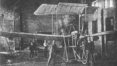
Libanski's Jaskolka in its original form, incorporating a detachable short-span wing with a movable flap, photographed in a Lwow hall immediately after completion.
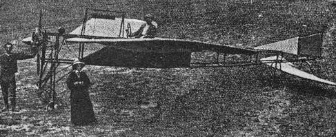
The Jaskolka, with the designer at the controls, seen here after modifications, as a pure monoplane, on Wiener-Neustadt aerodrome in the late summer of 1911.
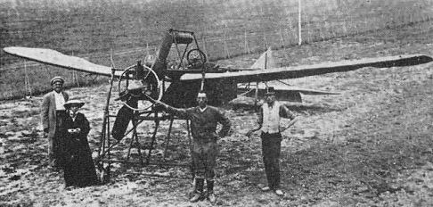
Another view of the Jaskolka in its final form on Wiener-Neustadt aerodrome.
Lipkowski's Helicopter
Jozef Lipkowski, a Polish engineer and inventor working in France and Russia, designed a huge helicopter-type flying machine in Russia at the end of 1904. According to descriptions in the contemporary press, the proposed aircraft featured two vertical co-axial shafts of steel tubes, to which two gigantic contra-rotating 'screws' (rotors) were attached. Each 'screw' consisted of two half-circular 'wings' (blades) which were supported by a long steel tube and comprised a wooden 'felloe' and steel 'spokes' covered with doped silk. A nacelle, accommodating the aviators and two engines, one for vertical and the other for horizontal flight, was mounted beneath. A rudder and a propulsive airscrew on a horizontal shaft were attached to the nacelle and provided means of control.
Early in 1905 the Pitulovskie Establishments in Petersburg constructed one complete rotor for the proposed aircraft for tests which were aimed at determining whether a vertical ascent would be possible. Ground trials with the gigantic rotor device, driven by an electric motor, yielded remarkably interesting results, confirming in full the designer's calculations. An official report, dated 16 March, 1905, and signed by Prof N. L. Shtchukin, who was appointed to witness and supervise the experiment, stated that Lipkowski's rotor, consisting of two 'half-wings' with an overall diameter of 16 m (52 ft 6 1/4 in) and a combined gross area of 200 sq m (2,153 sq ft), which were powered by a 35 hp (electric) motor, lifted 778 kg (1,715 lb) at 40 rpm, this indicating a lift/power ratio of 22.22 kg (53.35 lb)/hp (or more than twice as good as the then best achievements).
For these initial tests the half-circular blades were set at a very efficient angle of incidence of 3 1/2 deg. Later Lipkowski made further trials with the blades set at various angles from 5 to 8 deg. Allowing for unforeseen contingencies and the possible loss of rotor efficiency in a complete machine, the designer accepted a lift/power ratio of 12.5 kg (27.55 lb)/hp as the basis for his final calculations. Estimated weights of various elements of his giant helicopter included: two rotors 2,000 kg (4,409 lb); nacelle, steering and transmission systems 1,000 kg (2,205 lb); crew and fuel 1,000 kg (2,205 lb); two engines 4,500 kg (9,920 lb); the estimated gross weight of the machine being 8,500 kg (18,739 lb). Lipkowski proposed using a 700 hp engine for vertical movement and a 150 hp engine for horizontal flight. In later years he went to France to see whether he could obtain the required engines, but impressed with Wrights' and Bleriot's flights, he came to the conclusion that the future of flying belonged to fixed-wing aircraft and abandoned work on his pioneering project.
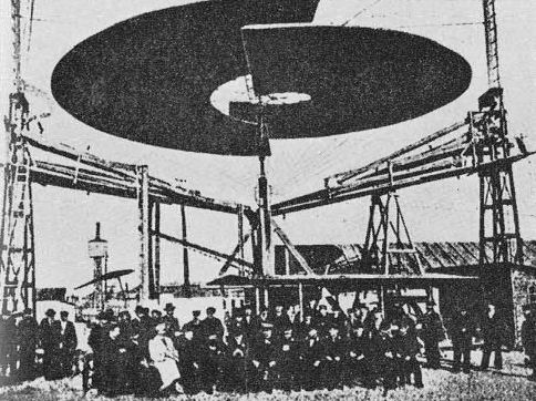
One rotor of Lipkowski's giant helicopter in a test rig at the Pitulovskie Establishments in Petersburg in March 1905.
Stibor Aircraft
Adam Ostoja-Ostaszewski, from Wzdow near Sanok, doctor of philosophy, lawyer and agriculturalist, was one of the very first aviation pioneers in Poland, beginning work in this field just before Tanski. A brief description of these experiments by the designer himself seems to be the main source of information about his designs to survive up to the present time and was until recently completely forgotten. This very inadequate and limited material, containing hardly any intelligible technical details, does not permit assessment of Ostoja-Ostaszewski's achievements and reveals the designer's considerable ignorance of the basic principles of mechanical flight. Because of this and the fact that his efforts remained very little known and had no bearing on the general development of flying in the country, one cannot attach too much significance to Ostoja-Ostaszewski's work, nor credit him with any 'firsts' in the history of early Polish aviation.
Ostoja-Ostaszewski mentioned that in 1908 he prepared a memorandum about his aeronautical activities for the Royal Society of London, but, in spite of extensive search, the author has not been able to find any trace of this document in London. The information about his designs quoted hereafter is based mainly upon his own statements.
Stibor No. 1. In 1892 the Krakow mechanic and pyrotechnist Mondrzykowski constructed under the direction of Ostoja-Ostaszewrski and at his expense a small flying model aircraft. The machine was propelled by 'a mechanism similar to the device which moves the firework called the Catherine-wheel.' The designer wrote: 'this aircraft, the Stibor No. 1, convinced me of the possibility of take-off from the ground by a heavier-than-air machine. I am convinced that this aeroplane was the first to takeoff under power of a combustion engine, the fuel for which also included petrol ... I also tested with Mondrzykowski a model of a different design. It rose to a height of about 100 m (328 ft) and remained in the air for a long time above the houses in the Krakow suburbs.' This latter model was obviously launched as a kite.
Stibor No. 2. Designed and constructed by Ostoja-Ostaszewski in Wzdow in 1908, the Stibor 2 was a full-size rotary-wing ornithopter-type flying device. The machine basically consisted of a large-diameter four-blade rotor, whose fiat-section blades were made to rotate and flap, and a vertical mast. The aircraft was powered by the muscle power of hands and feet, employment of the 'bicycle-type' transmission system being mentioned by the designer, who also envisaged the possible application of a light Antoinette engine as a supplementary source of power. On the evidence of the available photograph, however, the rigidity of the rotor blades appears to have been extremely poor, and the ideas behind the project, explained by the designer himself, were so naive and simple by the prevailing standards that they throw doubt on the competence of the whole concept.
Stibor No. 3. About 1908 Ostoja-Ostaszewski began construction of another aircraft, the Stibor 3, which he called the 'pneumatic aeroplane'. From the designer's very confused and rather incomprehensible remarks regarding this project, one could only deduce that this was an ornithopter provided with some sort of a compressed-air (or compressed-gas) system, aimed at improving the efficiency of its lifting surfaces. There is no evidence to suggest that this machine was ever completed in full-size form.
In March 1909, Ostoja-Ostaszewski entered for the world's first aviation meeting at Monaco as competitor No. 17 and was officially listed as an Austrian, but nothing is known about his participation in this event. However, the daily Dziennik Cieszyhski of 14 August, 1909, referring apparently to a model of the Stibor 3 or a similar machine launched as a kite, printed the following news item: 'Mr Ostaszewski from Wzdow recently left for Paris with an aeroplane of his own design to contend for the London Prize. Trials conducted with it permitted Mr Ostaszewski to achieve substantial results. Last time it stayed in the air for over an hour. The aircraft of Mr Ostaszewski is a biplane, its engine is driven by gas and the coupling of the wings with the engine permits full control of the kite.' He applied for patents to cover the design, but as far as is known these were never granted.
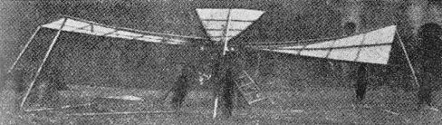
The Stibor No.2 rotary-wing ornithopter-type machine being prepared for tests in Wzdow.
Glider of the Piotrkow School Students
Five schoolboys from a secondary school in Piotrkow Trybunalski, Jan Gorzyriski, Lucjan Koenig, Waclaw Konarzewski, Stefan Laskowski and Jan Strahler, showed a great interest in aviation. Construction of kites was their favourite pastime. Their kite designs progressively improved and on some occasions were launched with a cat as passenger.
News about the first achievements of the early pioneers of flying excited the imagination of the young enthusiasts and encouraged them to undertake more ambitious tasks. They decided to build a man-carrying glider. Their design was based on the book by Michal Krol How to Build a Glider, which they obtained in Warsaw, but when they wanted to order 80 m (262.5 ft) of bamboo, which had to be imported from Japan, and other necessary materials they found they could not possibly afford the expense. They postponed their plans, but did not abandon them. For three years they patiently saved all the money they could until the required sum of 50 roubles (about ?5) was raised.
Then the materials were bought and construction of the glider began. Due to lack of tools and experience, the work progressed slowly and was frequently held up by the difficulties encountered. The original design was extensively modified, ailerons, rudders and elevators, which were absent from the glider proposed in Krol's book, being added. The craft was easy to dismantle and its components were kept in a small shed hired by the students, which also served as the workshop during construction of the glider. When the aircraft was finally completed, three and half years after the students first decided to construct it, a new difficulty arose. To fly it, special permission from the Russian governor had to be obtained. The whole matter was referred to officials in Petersburg and it took them three months to decide the issue. At last permission was granted on condition that the flights should be made from a pre-arranged place (this was the race track at Piotrkow) and that six mounted Cossacks and two policemen must be present during the tests.
In the last days of June 1913, the first flight was attempted. The mounted Cossacks proved useful, as they helped with the launch. The glider, piloted by Strahler, flew a distance of some 10 m (33 ft) and then due to lack of response to the aileron controls crashed to the ground. Strahler escaped with a few scratches. The glider was only slightly damaged and on the following day was ready to resume its tests, but on safety grounds the authorities banned all further attempts to fly it. The five students tried to continue their work in secret and intended to fly the glider from the lonely hills near their town, but the outbreak of World War 1 prevented this.
Construction: The glider was an equal-span biplane. The whole structure, including interplane struts, was built of bamboo and trussed with steel-wire ropes with strainers. All the fittings were made of sheet zinc by the students. The slightly cambered wings, with a total area of 26 sq m (279.9 sq ft), were covered with fabric. Ailerons were fitted to the lower wing only. A single, open vertical frame formed the fuselage. The pilot hung from his armpits supported by rests on the framework of the uncovered centre section of the lower wing and controlled the flight by hand-levers operating the ailerons, elevators and rudders. The cellular tail bay consisted of tailplanes, two full-chord elevators, which were mounted at the tips of the lower tailplane, and twin rudders. The rudimentary landing gear consisted of two wheels from a Farman biplane and a tailskid. The span of the glider was 10 m (32 f t 9 3/4 in).

The glider constructed by five determined schoolboys from Piotrkow Trybunalski.
Plage's Biplane
Emil Plage, the son of one of the founders of E. Plage and T. Laskiewicz Engineering Establishment in Lublin, studied aircraft engineering in Germany. In the first half of 1910, while under instruction with Rumpler, he evolved his own development of the Henri Farman biplane. The machine was completed at the beginning of July 1910, but, flown by the designer, crashed on 7 July on its first flight, at Berlin-Johannisthal aerodrome. The pilot escaped injury but the aircraft was wrecked.
Plage's biplane, of wooden construction with a lifting tail bay, was essentially similar to the Farman biplane. The elevator and ailerons were operated by the control stick, while both rudders, incorporated in the tail bay, were operated by the rudder bar. The machine was powered by a 50 hp Rumpler Aeolus eight-cylinder vee water-cooled engine. Dimensions included a span of 10.54 m (34 ft 7 in), length of 13.66 m (44 ft 9 3/4 in) and height of 3.64 m (11 ft 11 1/2 in).
Rosenman-Rozewski's Tandem Coleopter
Early in 1910, Dipl Ing Rosenman-Rozewski, from Lwow, evolved a study for a very interesting and unconventional design, which embodied two coleopter-type wings in tandem with a tractor airscrew inside each wing. According to the inventor, this configuration was to ensure excellent stability in flight and minimize damage to the lifting and control surfaces of the machine in case of a mishap.
A flying scale-model of the proposed aircraft was constructed in the spring of 1910 in Vienna, where Rosenman-Rozewski worked, and successfully tested in the air. The airscrews of the model were powered by rubber cords. The contemporary press reports seem to indicate that both coleopter wings could vary their angle of incidence for effective longitudinal stability control. No full-size machine was built and no details regarding the design are available. The Rosenman-Rozewski tandem coleopter model was shown at the First Aviation Exhibition in Lwow.
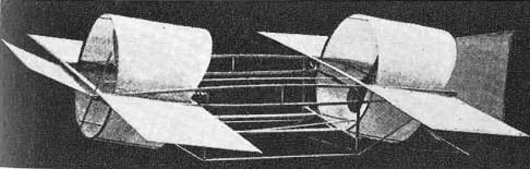
A flying model of the Rosenman-Rozewski coleopter-wing aircraft.
Rozum and Becheny's Monoplane
In Krakow, where no proper aeronautical organizations existed, the development of aviation activities was far more limited than in Warsaw and Lwow. However, a handful of Krakow pioneers and enthusiasts, undeterred by popular indifference, established close links with the ZASPL (Aviation Association of Technical University Students in Lwow) and 'Awiata' organizations in Lwow and secured understanding and moral support for their work from the Krakow Technical Society.
The first and only full-size aircraft to be built in Krakow before the First World War was a clean and pleasant looking monoplane, evolved by two Krakow technicians, Rozum and Becheny, the latter being of Czech extraction. The machine, somewhat influenced by the Bleriot Type No. XI, was designed in 1909 and completed at the Rudawski & Co workshop in April 1910. The aircraft was powered by a 50 hp four-cylinder radial engine driving a two-blade tractor airscrew, the engine and airscrew being designed also by Rozum and Becheny. According to contemporary press reports, engine trials proved highly successful, and the airscrew indicated a great tractive capability.
The monoplane, exhibited in one of the large halls in Krakow in May 1910, was the first powered fixed-wing aircraft to be completed in Poland and the first to be equipped with an indigenous aero-engine. No information is available about any flight attempts or the fate of the machine after its public display.
Construction: Rozum and Becheny's aircraft was a single-seat braced monoplane of wooden construction. The wing, a divided double-surfaced structure with an area of 16 sq m (172.2 sq ft), was attached to the fuselage longerons and lavishly braced by wires to the inverted V cabane on top of the fuselage and to the fuselage lower frame. Lateral stability was controlled by the wing-warping system. The fuselage, a rectangular-section open framework of ash, consisted of a deep forward section, extending under the wing, and a slim rear section. The forward section carried the engine, fuel and two-wheel landing gear, the pilot's seat being situated at the head of the frame under the engine. The tail unit consisted of a tailplane, elevators, and a fin which was attached to the end of the fuselage frame. Dimensions included a span of 8 m (26 ft 3 in) and length of 7 m (22 ft 113/4 in). The empty weight was 260 kg (573 lb).
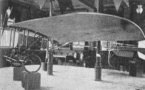
Rozum and Becheny monoplane on show in Krakow in May 1910.
Rudlicki Gliders
Jerzy Rudlicki began experimenting with large kites at the age of 15, while still at school in Odessa, in 1908. These activities led him to the construction of man-carrying gliders, the first of which, Glider No. 1, completed early in 1909, was not much more than a man-carrying kite with flat-section biplane wings, a single vertical frame and fixed vertical and horizontal tail surfaces. On 3 March of that year Rudlicki was launched, by two of his friends pulling the ropes, from open land near the Odessa park and became airborne for the first time. Unable to maintain balance, the young constructor realized, only when actually in the air, that some means of control was necessary to continue the flight successfully. However, by then it was too late to do anything about it and after a brief flight the aircraft crashed. Rudlicki received superficial bruises and the remnants of his glider were quickly taken apart by souvenir hunters.
Undaunted by these rough beginnings, Rudlicki immediately proceeded with the construction of an improved glider incorporating rudimentary controls. In 1909 and 1910, altogether he completed nine gliders, their designs progressing from very simple structures, in which the pilot hung in the uncovered centre section of the wing and landed on his own feet, to sophisticated powerless aircraft equipped with comprehensive control systems and landing gear. In search of the best solutions he experimented with a number of layouts and produced a variety of configurations, which revealed an enquiring and adventurous mind and a fertility of ideas on the part of the young designer, who thus gained the distinction of becoming one of the most creative Polish constructors of this early era. Launching methods were also improved and, later, horse traction was used, but all gliding took place from flat ground in Odessa. In the later stage of his work on gliders Rudlicki was joined by Dobrowolski.
In view of the limited amount of documentary material available, not all of the Rudlicki gliders can be described. Glider No. 2 had equal-span two-bay biplane wings, a forward elevator on two outriggers in front of the wing, and a single vertical frame, which carried at its rear end a rudder and horizontal stabilizer, the pilot's body being suspended from the centre section of the lower wing. Its gross lifting area was 20 sq m (215.3 sq ft) and the span 7.5 m (24 ft 7 1/2 in). Glider No. 3 was generally similar, but incorporated a superior control system which included ailerons, a rudimentary seat for the pilot and various other refinements. Another early type was a tandem-wing monoplane featuring a main wing, which accommodated the pilot in the centre section, a smaller supplementary wing in front and an elevator surface at the rear. This glider had a total lifting area of 15 sq m (161.5 sq ft) and a span of 7.5 m (24 ft 7 1/2 in), while its basic weight was about 25 kg (55 lb). All these 'first-generation' models employed single-surfaced wings, with cotton fabric loosely attached to the framework of ribs laid across transverse spars.
Progressive improvements introduced to each successive type led Rudlicki to the development of the 'second-generation' designs, which embodied aileron, elevator and rudder controls. His last three gliders, Nos. 7, 8 and 9, were all unequal-span single-bay biplanes with a forward supplementary elevator carried on outriggers in front of the single-surfaced cambered wings. Gliders Nos. 7 and 8, which were essentially similar and featured double fuselage frames and triangular twin rudders, differed from each other only in detail, the latter employing a wheel undercarriage. Glider No. 9, spanning 9 m (29 ft 6 3/4 in), was a two-seater and incorporated a single vertical rear fuselage frame. This last type was displayed in the aviation hall of the Industry and Commerce Exhibition, held in Odessa from the end of 1910 until the spring of 1911, which was illuminated at night by lights carried by four large kites constructed by Rudlicki. These kites were later bought for the court of the Shah of Persia.
In appreciation of these aviation activities, Rudlicki was awarded a special diploma by the Odessa Branch of the Tsarist Russian Technical Association, which, commended his contribution to the advancement of aeronautical knowledge.

Rudlicki's glider No.1, flown by the designer, during its first and only brief flight in Odessa on 3 March, 1909.
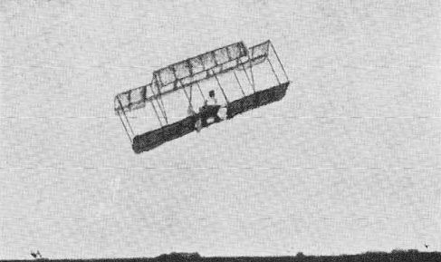
Glider No.2, designed and flown by Rudlicki in 1909.
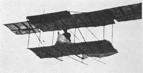
The Rudlicki glider No.7 in flight.

The improved Rudlicki glider No.8 with a wheel landing gear.
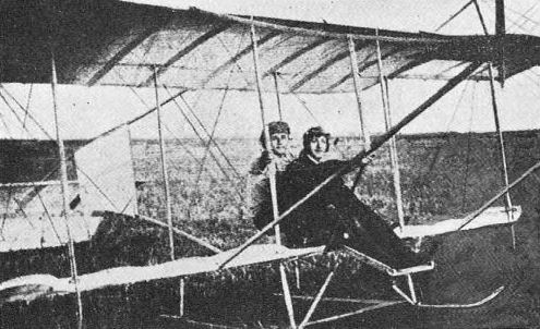
The last of the series of the early Rudlicki gliders, the two-seat No.9, with Rudlicki in front and Dobrowolski behind him.
Rudlicki R-I
In 1912-13 Jerzy Rudlicki prepared a study for his first powered design, a small tractor monoplane, which was retrospectively designated R-I. Construction of the airframe, undertaken by Rudlicki and Dobrowolski, began in Odessa towards the end of 1913, being assembled in the post-exhibition aviation hall, and the Odessa Flying Club, which helped the enthusiasts, supplied a 25 hp Anzani three-cylinder air-cooled semi-radial.
The machine was completed in the late summer of 1914 and was test-flown at the outbreak of war, during Rudlicki's absence, by his friend, Capt Grekov of the Combat Maritime Battalion. The aircraft is believed to have made three or four flights, but was subsequently damaged during an emergency landing after the failure of the unreliable Anzani engine.
Meanwhile Rudlicki evolved two developments of the basic R-I design adapted for more powerful engines, the R-II with a superior double-surfaced wing equipped with ailerons, and the R-III, which in addition to the improvements embodied in the R-II, was to dispense with the forward elevator, but neither of these projects progressed beyond the drawing-board stage. During the war, the designer, who distinguished himself in service with the Russian Imperial Flying Service first as an observer and then as a pilot, evolved proposals for revised developments of the Spad A4 (which had the observer's cockpit in front separated from the pilot's cockpit by the airscrew). These were to have been the R-IV with a rotary engine and the R-V with a water-cooled engine, but neither was constructed.
Construction: The R-I was a light single-seat wire-braced monoplane of wooden construction. The wing, with an area of 15 sq m (161.5 sq ft), was a two-spar structure with cambered ribs covered with fabric on the upper surface only. The wing, attached to the fuselage upper longerons and braced by wires to the cabane on top of the fuselage and to the landing gear framework, was provided with a warping system. The fuselage, with a quadrilateral forward section and triangular rear section, was covered with plywood and fabric. The forward elevator, operating in conjunction with the rear elevator, was carried on sledge-shaped outriggers in front of the airscrew, and the tail unit was a conventional braced monoplane structure incorporating a fin, rudder, tailplane and elevator. The undercarriage comprised a cross-axle and two mainwheels attached by shock-absorbing rubber cords to the sledge-shaped outrigger structure. The overall dimensions of the R-I included the span of 9 m (29 ft 6 3/4 in) and length also of 9 m (29 ft 6 3/4 in). Its loaded weight was 230 kg (507 lb).
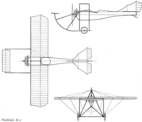
Rudlicki R-I
Aquila Monoplane
In 1909 the brothers Rudolf and Wincenty Schindler of Krakow evolved a study for a multi-seat tractor high-wing monoplane of very advanced concept. At the end of October of that year a flying scale-model of the proposed aircraft, powered by a rubber-cord driven airscrew, was displayed by the brothers in the Technicians' House in Krakow. The model, which aroused considerable interest, made a successful flight inside the exhibition hall, taking-off from the floor under its own power. The Schindler brothers came into contact with Henryk Brzeski, the Polish engine inventor working in Vienna, who agreed to help them with the development of the machine and to design a powerplant for it. Early in 1910 the project, which became known subsequently as the Aquila, was revised by the Schindler brothers and Brzeski working together, the changes introduced including the replacement of the normal control method and tail unit by an unconventional control system which dispensed with the vertical tail surfaces. Construction of the aircraft began in Vienna.
Henryk Brzeski was the creator of a reaction-free bi-rotary engine, in which the cylinders and crankcase rotated one way and the crankshaft the other. The first of his experimental engines built on this principle appeared in 1907 and soon the rights to a number of his engine patents and designs were purchased by Gnome and Siemens and later also by Daimler. For the Aquila monoplane Brzeski evolved the 50 hp 'Iskra' ('Spark') seven-cylinder bi-rotary engine (believed to be privately built by Brzeski in the Siemens factory), which drove huge contra-rotating two-blade airscrews.
The Aquila, equipped with the unique Brzeski powerplant and one of the first in the world to employ contra-rotating propellers, was rolled out on Wiener-Neustadt aerodrome for the first time on 18 September, 1910, on the occasion of the Imperial review of Austrian aviation by the Emperor Franz Josef. The machine, provided with three seats and very well built, was described by the contemporary press as one of the most impressive among the 23 aircraft assembled for the review. The Emperor showed particular interest in it and, talking to Brzeski, expressed satisfaction that Poles had begun work in the field of aeronautics and wished them every success. Some days later the Aquila monoplane began its trials. Unfortunately it was destroyed in a crash soon after take-off on its first flight, the complicated and ineffective control system being presumably the cause of this mishap. It is believed that the Schindler brothers and Brzeski evolved further aircraft projects at the time, but details of these are lacking.
After the war Brzeski continued his work on bi-rotary engines in Poland. During the 'twenties he designed a few experimental power units of this type, and a prototype of his 120-125 hp radial engine, which had five parallel cylinders mounted horizontally and was of exceptionally small overall diameter, was completed by the Pocisk factory in Warsaw in 1926. The engine ran successfully on a test stand for many hours and showed great promise. The Polish Skoda Works contemplated its quantity manufacture, but lack of orders prevented this.
Construction: The Aquila was a three-seat open-frame wire-braced high-wing monoplane of bamboo construction. The wing, of elliptical planform, was a fabric-covered double-surfaced multi-spar structure and incorporated a warping system which controlled lateral stability. The wing was attached to the top of the fuselage frame and heavily braced with wires to cabanes above and below the wing and to the fuselage frame. The triangular-section open bamboo frame constituted the fuselage and carried three seats in tandem, the first seat being equipped with an inclined steering wheel. The positioning of the seats, situated unusually far aft, and of the fuel tank, which was carried under the fuselage frame between the first and second seat, was rather surprising as it was bound to result in a very considerable C.G. movement. An oil tank, with a small pump beneath, was attached to the top frame under the wing. The tail unit consisted of a one-piece horizontal stabilizer, the design and bracing of which was very similar to those of the wing and which also embodied a warping system. The wing- and tail-warping systems were linked together, and various combinations of movements of these surfaces were to provide the means of control in all three planes. The landing gear, reminiscent of that of the Bleriot Type No. XI, consisted of two front wheels and a tailwheel, all wheels being provided with spring shock-absorbers. Overall dimensions included a span of 10 m (32 ft 9 3/4 in) and a length of 10 m (32 ft 9 3/4 in). Estimated emptv and maximum loaded weights were in the region of 300 kg (661 lb) and 550 kg (1,212 lb).
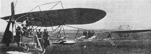
The Aquila monoplane photographed on Wiener-Neustadt aerodrome during the Imperial review of Austrian aviation, on 18 September, 1910. Note positioning of seats.
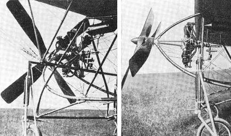
Two views of the revolutionary Brzeski-designed powerplant of the Aquila monoplane, the 50 hp 'Iskra' seven-cylinder bi-rotary engine driving contra-rotating airscrews.
Monoplane of the 'Three'
Three Lwow teenage students, Aleksander Sokalski, Kazimierz Baszniak and Wlodzimierz Semiula, built an exceedingly primitive tractor monoplane in the second half of 1910. The airframe was completed in November of that year and stored in the Rubczynski garage in Lwow for the winter. The young designers hoped to equip their machine with an engine and begin trials during the following spring, but this never happened.
The aircraft of the 'Three' was a light single-seat open-frame wire-braced high-wing monoplane. Its framework was built entirely of wood and its controls appeared to consist of a rudder and movable horizontal tail surfaces, which acted either in unison like elevators, or differentially, like ailerons. No details regarding the structure are available, but the general configuration and salient features of the design are apparent from the photograph reproduced here.
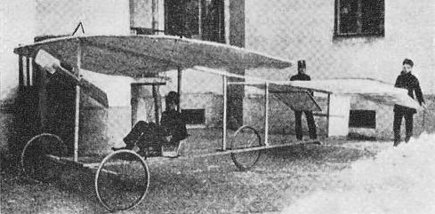
The very primitive monoplane of the "Three', constructed by Lwow teenage students in 1910.
Lotnia Gliders. Taking his favourite bird, the stork, as the master pattern, Tanski began developing a primitive man-carrying glider almost at the same time as his work on flying models. The machine, which was progressively improved and tested in three versions, became known as the Lotnia. According to his own account, Tanski began construction of the glider in Janow Podlaski in 1894 with the help of a carpenter.
Work on the Lotnia seemed to have progressed rather slowly. The first attempts to fly it were made in June 1896, in Janow Podlaski, but these proved the inadequacy of the device and its operating technique. The glider, consisting only of a crude frame and a stork-like wing, had to be held by its 'pilot' with his hands above his head. The 'pilot', imitating a heavy bird, had to run quickly against the wind, bounce his feet off the ground and become airborne. During the first tests the original Lotnia proved unstable and uncontrollable; in spite of several attempts Tanski was unable to hold it at the desired angle and during his last run he lost his grip on the machine and it crashed upside down. The damaged glider was repaired and improved, modifications including the addition of a small adjustable horizontal tail to improve stability. Realizing the futility of his efforts to lift from the flat ground, Tanski built a 3.5 m (11 ft 6 in) high wooden scaffold, but jumps from it were also inconclusive.
The first and second variants of the Lotnia possessed a divided 'stork-type' monoplane wing with an area of 7 sq m (75.3 sq ft), which consisted of the leading-edge limewood spar and osier ribs and supplementary stiffeners. The single-surface wing, covered with silk gauze pasted over with tissue-paper, was attached to the top frame longerons and braced by short inverted V struts to the lower part of the frame. Each wing panel, easily detachable, was set at a pronounced dihedral angle. The 'fuselage' frame was a sledge-like structure built up of lime and aspen. One triangular vertical surface on each side at the rear of the frame, and the horizontal plane above them, were covered with gauze for stabilizing purposes. The second variant of Lotnia was provided with an adjustable fan-shaped flat-section tailplane. The approximate span of the glider was 8.6 m (28 ft 2 3/4 in), the length (with the tail added) 3.2 m (10 ft 6 1/4 in) and the basic weight 18 kg (40 lb).
Due to frequent damage in various crashes and accidents the Lotnia was constantly repaired and rebuilt, and in the years 1897-98 Tanski evolved and constructed a considerably revised third version of the design. Coming to the correct conclusion that the original wing was too small to support him, he enlarged its area to 12 sq m (129.2 sq ft) and, to improve stability, lengthened the whole structure, adding the bigger horizontal tail, which had an area of 1 sq m (10.8 sq ft). He also covered two forward vertical areas of the frame (one on each side) with gauze, in addition to the rear areas. According to Uminski's contemporary articles and estimates from photographs, the span of the third Lotnia version was about 10.8 m (35 ft 5 1/2 in) and overall length 3.8 m (12 ft 6 in). Its basic weight was about 25 kg (55 lb).
In 1898 the improved Lotnia made numerous gliding attempts from the previously mentioned scaffold, as well as from a flat meadow in Janow Podlaski, several of them being witnessed by the designer's friends, Kocent-Zielinski and Lukawski. About the tests from fiat ground, Tanski wrote himself: 'From the moment of the first step forward the machine became lighter and during my run I not only did not feel its weight, but on occasions became supported by it. Running against the wind long jumps were possible. I had the proof of how difficult this operation really was, when two of my friends, Zielinski and Lukawski, came to visit me. None of them could hold the machine in his hands even in light wind' and the device 'either overturned or hit the ground with its fore end'. During one of these prolonged jumps in 1898 Tanski was said to have reached a height of some 2 m (6 1/2 ft) and covered a distance of some 30 m (98 1/2 ft), this being claimed as the world's first ascent by a man from flat ground without assistance from any source of power.
Describing his jumps from the scaffold, Tanski said: 'I mounted the scaffold by a ladder, holding my machine above my head. The main difficulty was to gather speed and position the machine correctly. The platform was short and not very secure ... Moments of jump and descent very short ... However, further experiments gave me the chance to feel and utilize the lifting force of my big wings. Some jumps became longer and descent was markedly slower.' These flights, although very short and inadequate, were nevertheless a great pioneering achievement and the first in Poland on a heavier-than-air device to be historically documented.
At that time Tanski was thinking about transferring his experiments to hilly regions and began to evolve the design for a new, more advanced glider, which was to be provided with twin pusher airscrews driven by the pilot's feet, but a disastrous financial situation forced him to postpone these projects and concentrate on painting so as to repair his resources. During the next five years (1899-1904), living in Warsaw, Paris (1901-02), and then again in Warsaw, where he settled permanently, Tanski devoted most of his time to painting. However he soon turned part of his Warsaw studio into an aviation workshop and in 1904-05 resumed design work on a man-carrying glider.
Experimenting with the general concept for the new project with the help of models, he prepared a study for a full-size tail-first machine and for a muscle-powered foot-operated propulsion system driving two pusher airscrews, which was later to be installed in it. It is interesting to note that, contrary to the common practice of contemporary designers of the muscle-powered aircraft, Tanski intended to use muscle power only to propel the airscrews and never to flap the wings. About the same time he became progressively interested in the helicopter idea, but as his limited funds did not permit him to build both machines, he eventually abandoned the tail-first glider in favour of the latter.
News items about the Lotnia and Tanski's glider experiments inspired Ryszard Bartel (later a well-known aircraft designer) to follow in Tanski's footsteps, and in 1911, at the age of 14, he evolved his first glider, which in certain respects resembled Tanski designs.
In 1956, on the 60th anniversary of Tanski's first pioneer gliding attempts in Poland, the Aeroclub of the Polish People's Republic established the Tanski Medal, which is awarded yearly to a Polish glider pilot for the most outstanding gliding achievement of the year.
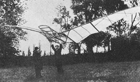
A documentary photograph of the Lotnia I during its early unsuccessful tests in Janow Podlaski in 1896.
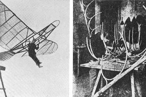
Left, a documentary photograph showing Tariski on his Lotnia III during one of its short glides from the scaffold, presumably in 1898. Right, Tariski's workshop at Mazowiecka Street in Warsaw with work in progress on blades for a large full-size helicopter.
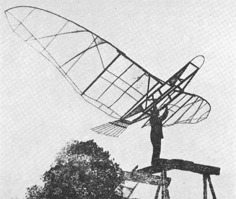
A dramatic photograph of Czeslaw Tanski and his Lotnia III before a gliding jump from a scaffold, presumably taken in 1898.
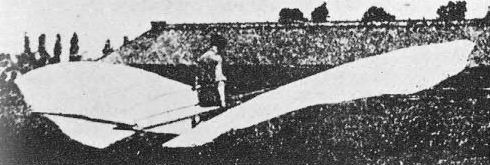
The improved Lotnia III being taken for another series of gliding attempts in 1898.
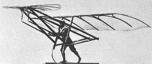
A scale-mode! of the proposed tail-first glider which was to be later developed into a muscle-powered aircraft.
Tanski's Helicopter. During 1905-07 Tanski concentrated on the development of a helicopter. After tests with models, which were used to study the stability and lift values of helicopter-type designs, he began construction of a full-size helicopter. This was built in his workshop at Mazowiecka Street and completed in 1907. It consisted of a metal-tube mast composed of two co-axial shafts to which two two-blade rotors, rotating in opposite directions and set one above the other, were fixed, a very progressive configuration by the then standards (on the other hand the machine did not possess any means of control and was designed simply to rise and descend vertically). The rotor blades, with leading-edge limewood spars and osier ribs, were covered with silk gauze pasted over with tissue-paper on the upper surface only. Each blade was braced with two struts to the metal mast above. The 'pilot' was attached to the mast by a special belt harness and operated a hand-driven gearbox propelling the rotors. The approximate overall span of each rotor was 8 m (26 ft 3 in) and the overall height of the mast (including its harness extension fixture) 2 m (6 ft 7 in).
Tests indicated that the pilot's muscle power gave a maximum lift of only about 12 kg (26 lb) which was not nearly sufficient to raise the machine and its operator. In 1909 Tariski adapted the machine for a 2 1/2 - hp Anzani two-cylinder vee engine, but this powerplant also proved inadequate and, according to the designer, the cylinders of the engine became red hot after a short while because of the complete lack of cooling. Later, Tanski was thinking of installing a small, light but more powerful engine, and in the autumn of 1910 he asked his son, who was in France, to look for a suitable powerplant. His helicopter survived as a museum piece until the last war and was displayed at the Lwow Aviation Exhibition in 1938.
During the inter-war era Tanski returned to the problem of vertical flight and in 1927 built and tested four experimental helicopter models. This work, however, did not seem to offer a sound basis for a practical full-size machine and appeared to be limited only to the study of a primitive rotor concept. In 1934 a special commission of I.B.T.L. (The Institute of Aviation Technical Research) investigating his helicopter proposals said in an official statement: 'The works of Mr C. Tanski from the period of the beginnings of world aviation, because of the era when they were accomplished and their successful form, are today of great historic importance for Poles. They can be regarded as the first successful efforts in corresponding fields in world aviation. Mr Tanski's collaboration in the field of helicopters now offered would be of no use at the present time.'
Early in 1939 Tanski again proposed undertaking work on an experimental helicopter and asked L.O.P.P. for a subsidy for the project. In April 1939, the L.O.P.P. Central Committee replied that it could not grant such a subsidy before examination and approval of detailed calculations and project design drawings, but these were never submitted.

An original photograph of Tanski's full-size helicopter with a hand-operated mechanism. The machine is seen here soon after completion, in the courtyard of 2 Mazowiecka Street, Warsaw, where Tanski had his workshop.
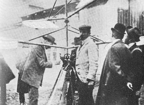
Tanski's helicopter fitted with a 2 1/2 hp Anzani two-cylinder vee engine, with the designer (in white jacket) standing beside the machine, photographed in the courtyard at 2 Mazowiecka Street.
Latka Monoplane. In 1909 Tanski had completed a study for a single-seat monoplane named the Lattka (Libellula), which incorporated an extraordinary feature: the angle of incidence of its entire wing could be varied in flight. A very large drawing of this project was prominently displayed at the 'Exhibition of Czeslaw Tanski's model flying machines' in December 1909, which was intended to raise some money towards the cost of building the aeroplane (estimated at 3,500 roubles or some ?370), and construction of its first components began before the year was over.
Due to the cramped conditions in his Mazowiecka Street workshop and various other difficulties, work on the Latka, for which Tanski managed to obtain a 25 hp Anzani three-cylinder air-cooled semi-radial engine, progressed at a very slow rate, and as time went by the design was modified and improved. Counting on the possibility of getting a 50 hp Gnome rotary engine, the designer strengthened the structure. Frequent failures of contemporary undercarriages led him to pay particular attention to the development of a strong and safe landing gear, which was continuously revised and eventually materialized as a conventional and very heavy structure. Its final configuration appeared to be an unfortunate choice, inferior to the previous highly original, flexible and lighter design.
By the early autumn of 1910 Tanski completed the airscrew, landing gear and a large part of the fuselage, but limited space prevented him from constructing the wings. He had to find larger premises and considered moving either to the Aviata factory in Mokotow or outside Warsaw. On 8 October, 1910, he transported all the parts of his machine from the Mazowiecka Street workshop to the Aviata hangar No. 2 and in the middle of that month began constructing the wings. At the end of 1910 he transferred his workshop to the Aviata hangar No. 7, which he liked better. During the winter, work on the Latka almost came to a halt, and the aircraft, fitted with the 25 hp Anzani engine driving the Tanski two-blade airscrew, was eventually finished only in the autumn of 1911.
Taxi-ing trials and take-off attempts were made at Mokotow aerodrome mainly by Stanislaw Supniewski and on one or two occasions by one of the earliest and best-known Polish pilots, Michal Scipio del Campo. The latter, referring to the 'only interesting feature' of the design, the variable angle of incidence of the wing, wrote: The engineering solution of this idea consisted of a system of pulleys connected by an ordinary hemp rope. One could imagine how this would function in the air. By the grace of providence this contraption never left the ground, otherwise a disaster would have been unavoidable. Looking back at this, I had to be very foolhardy to attempt to fly it.'
After the first unsuccessful take-off attempts the Latka was provided, in 1912, with a triangular fin and rudder, but this did not persuade it to leave the ground, and the aircraft proved to be a total failure.
Construction: The Latka was a single-seat wire-braced monoplane of wooden construction. The elliptical wings, attached to the fuselage top longerons by means of short, heavy main spars around which they pivoted to vary the angle of incidence, were built up of three light spars and curved lattice ribs. The high aspect ratio wing panels, of the double-surfaced fabric-covered variety, were braced by steel wires to the inverted V cabane on top of the fuselage and below to undercarriage frame members. Wing warping was used to maintain lateral stability. The fuselage consisted of a rectangular wooden forward section, which carried the engine, undercarriage frame and pilot's seat, and a triangular rear section constructed of bamboo sticks. The tail unit initially consisted of a one-piece movable horizontal surface only, but later the fin and rudder were added. Each unit of the divided landing gear consisted of a pair of wheels attached to a skid, and twin bamboo tailskids under the tail. Dimensions, estimated from Tanski's own drawings, included an overall span of 14.4 m (47 ft 3 1/4 in) and overall length of 9.4 m (30 ft 10 1/4 in). Weights are not known.
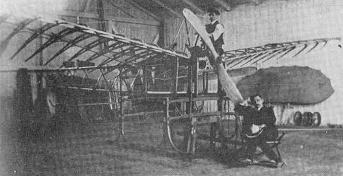
The Latka monoplane under construction in the Aviata hangar No. 7, with the blades of the helicopter, standing in a corner of the hangar, visible in the background.
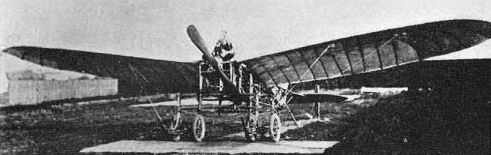
The unsuccessful Latka monoplane in its final form, with triangular fin and rudder, photographed in the Aviata factory premises in 1912.

Structural details of the Latka monoplane, showing the interesting design of the wing and a sideview of the forward fuselage and varying angle of incidence of the mainplane, as drawn by the designer presumably in 1910.
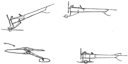
Tanski's sketches depicting studies for the Latka monoplane with an interesting, light and flexible landing gear, and a heavy landing gear which was eventually used.
Weber's Biplane
In the winter of 1909-10 Dipl Ing Jan Weber, lecturer at the Lwow Technical University, began studies for a completely original two-seat open-frame pusher biplane. The design, developed with the assistance of Prof Zygmunt Sochacki, was the first Polish project to have the overall concept and all details calculated mathematically and fully investigated theoretically before construction began.
Building of the airframe, which incorporated various changes and refinements as compared with the original study, was delayed by lack of necessary capital, but in June 1910, the Aircraft Building Share-holders Company was established (staff and students of the Lwow Technical University forming the major proportion of its members) and this company provided financial backing for the enterprise and launched a subscription fund. The partially completed machine was displayed at the First Aviation Exhibition in Lwow, which was staged at the University from 1 September to 15 October, 1910.
Powered by a 50 hp Korting four-cylinder water-cooled inline engine driving a two-blade pusher Drzewiecki airscrew, Weber's biplane was ready for its first flight in the late autumn of 1910. The attempt, which presumably took place in November, was undertaken by the designer (who had no experience as a pilot) in Blonia Janowskie in the presence of a large group of students from the Machine Building Faculty who helped with the construction work, but this ended in a mishap. The aircraft left the ground, but seconds later collided with a tree and was severely damaged, its pilot escaping with cuts and bruises. It was decided to defer further trials until the following spring, and the repaired airframe was stored in a shed for the winter. Unfortunately, the shed collapsed under the weight of snow and the machine was completely crushed.
Construction: Weber's aircraft was a two-seat unequal-span two-bay biplane, built mainly of ash with the addition of certain steel-tube elements. The wings, of double-surfaced type, had an area of 40 sq m (430.5 sq ft). The top wing, with a chord of 1.8 m (5 ft 11 in), featured coarsely dihedralled tips. The bottom wing had a span of 10 m (32 ft 9 3/4 in) and chord of 2 m (6 ft 7 in), with its leading edge projecting forward of that of the top wing. Two aileron surfaces were carried on wires in front of the top wing. The fuselage was an open framework trussed with wires. The pilot's position, equipped with a control wheel and rudder bar, was situated between the wings, the passenger sitting behind the pilot. The engine, mounted on struts, was further aft. The tail unit consisted of a rudder and a fixed tailplane with a span of 5 m (16 ft 5 in) and chord of 1.2 m (3 ft 11 1/2 in). The elevator, of the same overall span including its fixed tips, was carried on forward outriggers in front of the top wing. The landing gear comprised two mainwheels, attached by rubber cords to wooden skids, and a tailwheel. Overall dimensions included a span of 12 m (39 ft 4 3/4 in), length of 11.5 m (37 ft 9 in) and height of 3.5 m (11 ft 6 in). Empty and maximum loaded weights were 310 kg (683 lb) and 500 kg (1,102 lb).
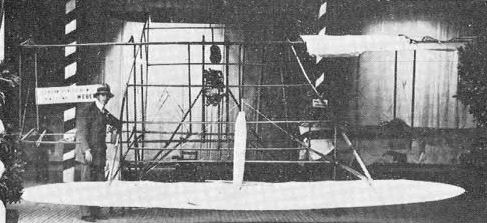
The partially-completed Weber biplane at the First Aviation Exhibition in Lwow. A comparison of this photograph with the drawing of the original study reveals a number of changes which were introduced to the design.
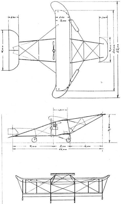
An original drawing of Weber's biplane from the early part of 1910, believed to be the oldest contemporary three-view drawing of a Polish-designed powered aircraft in existence. Dimensions on the drawings are in metres.
Wrobel's Monoplane
A Pole named Wrobel from Opole in Silesia (then belonging to Germany) completed a monoplane of his own design in the late spring of 1910. The machine was among the ten aircraft displayed at the Silesian Flying Club Exhibition, which was held in Wroclaw between 19 and 23 June, 1910. According to contemporary press reports, Wrobel's monoplane, described as 'a very competent design, had already made some flights before appearing at the exhibition (Flugsport, 1910). Wrobel should therefore be regarded as the second Polish designer (after Warchalowski) to develop a successful and controllable aeroplane.
The machine was a single-seat wire-braced high-wing monoplane of conventional configuration and featured a multi-spar wing based on natural forms. The pilot's seat, with a steering wheel in front, was situated under the wing. The powerplant consisted of a 25 hp Wunderlich three-cylinder semi-radial water-cooled engine driving a two-blade tractor airscrew.
No details concerning the structure or the subsequent fate of the aircraft are available.
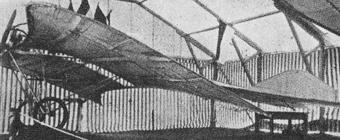
The Wrobel monoplane as it appeared at the Silesian Flying Club Exhibition in Wroclaw in June 1910.
Zalewski W.Z.II
Wladyslaw Zalewski was determined to begin flying at the earliest opportunity, and as the work on his W.Z.I biplane absorbed more and more time and the completion of the machine had to be put back year by year, the young constructor grew impatient and decided to find simpler and cheaper ways to satisfy his desire to fly. Early in 1912 he designed a primitive monoplane glider, retrospectively designated W.Z.II, and with the help of his brother Boleslaw built this aircraft in Milanowek in three weeks in the spring of 1912, at a total expense of only 24 roubles (some ?2.50).
The design was completely original, but initial tests conducted in 1912 revealed some shortcomings in the structure. After modifications, which included the additional stressing of the fuselage frame with extra wires, to improve rigidity, and the slight revision of the vertical tail surfaces, the results of the flight attempts became more satisfactory, and, as the designer gained experience in handling the glider, they grew progressively better. All the gliding was carried out from small hills in the Milanowek area in winds of 6-8 m/sec (13-17 mph). The glider was launched by means of two ropes pulled by Zalewski's friends, and the pilot had to bounce his feet off the ground a few times to become airborne. At first, 'hops' of some 30 m (98 ft) were made at a height of about 1 m (3 ft), but in 1913, when four or six people, instead of two, worked the ropes, longer distances were covered. The aircraft, which proved to be stable and quite easy to control, was frequently pulled by young boys at a leisurely run for 50-100 m (164-328 ft) and then began a short free glide.
The W.Z.II was damaged on a number of occasions, but never seriously and its pilot was never hurt. Only once was it involved in a more severe mishap, when the wooden lever operating the wing-warping control broke away in the air. Zalewski intended to replace it by a steel device, but circumstances prevented him from finishing this modification and he had to abandon further flights. The craft could be dismantled quickly to facilitate storage and for easy transport to suitable gliding sites.
Construction: The W.Z.II was a single-seat braced high-wing monoplane glider of wooden construction. The wing, with an area of 9.5 sq m (102.3 sq ft), was built up of a main spar, two auxiliary spars (the front one forming the leading edge), and curved ribs, and was covered with fabric on the lower surface only. The wing panels, which were individually braced by a kingpost system, were attached to the longerons of the fuselage frame, the trussing of the wing and the fuselage being arranged from a supporting cabane on top of the forward fuselage frame. To maintain lateral stability a wing-warping system was employed. The fuselage consisted of the rectangular horizontal frame with a reinforced forward portion, to which the inverted V cabane and two transverse Vs, carrying a long single landing skid, were attached. A bicycle-type saddle was carried on wires under the main fuselage frame. The frame longerons rested on the pilot's shoulders and were secured to them by straps. The cruciform monoplane tail unit, a wooden structure with fabric covering, consisted of a fin, a divided rudder and an undivided hinge-mounted elevator, which was attached to the rear of the fuselage frame. The top part of the rudder was operated jointly with the wing-warping system by movements of a hand-lever, the elevator being operated by another hand-lever, while the lower part of the rudder was operated independently by a rudder bar. The shock-absorbing skid, used for landing in the case of greater impact resulting from a steep descent, was below the pilot's knees. Dimensions included a span of 7.5 m (24 ft 7 1/2 in) and a length of 4.8 m (15 ft 9 in). Empty weight was 24 kg (53 lb).
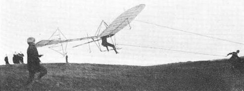
The W.Z.II glider, piloted by Wladyslaw Zalewski, being launched on one of its successful glides in the Milanowek area in 1912.
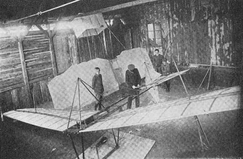
The W.Z.II glider in the Milanowek theatre hall in 1913. Babinski's second glider is resting against a wall.
Zalewski W.Z.I
Wladyslaw Zalewski began his design career while still a young student at the Wawelberg Technical College in Warsaw. In 1908, at the age of 16, he designed and built two rubber-cord driven model monoplanes based on natural forms. One of these was of a heavily loaded type, while the other was a 'light' model. Both models were tried in the air with good results, but the lighter machine performed best, on occasions covering distances in excess of 60 m (197 ft). Studying the behaviour of his models in the air, Zalewski gained knowledge and experience which enabled him to undertake work on full-size aircraft.
In 1909 Zalewski conceived a full-size light pusher biplane, which in general features resembled a scaled-down Henri Farman machine. Construction of this elaborate aircraft began in December 1909, and was continued in a disused village theatre near the designer's home in Milanowek near Warsaw. Due to lack of sufficient time and funds, this work progressed at a very slow pace and was frequently interrupted, various modifications and improvements meanwhile being introduced to the structure. Zalewski originally intended to power his biplane with a 25 hp two-cylinder rotary engine of his own design, but as he was unable to find a contractor willing to cast the necessary parts of the engine, this idea had to be abandoned, and eventually a 28 hp Delfose three-cylinder rotary engine was to be used. The engine was to be mounted in the cut-out at the rear of the lower wing and drive a pusher airscrew.
By 1913 the airframe reached the final stages of assembly, but by that time all aeronautical activities in Russian-occupied Polish territory were banned, and the aircraft, which was later retrospectively designated W.Z.I, in Zalewski's personal designation sequence, was never completely finished. Various parts and materials for the biplane, stored at Milanowek, were used 12 years later in the construction of the W.Z.XI Kogutek I.
Construction: The W.Z.I was a single-seat unequal-span two-bay biplane of Henri Farman configuration and wooden construction. The wings, with a total area of 22.5 sq m (242.2 sq ft), were built up of curved lattice ribs on two laminated spars, the front spar forming the leading edge, and were covered with rubber-proofed fabric on both surfaces. The top wing had dihedral extensions outboard of the outermost struts. Lateral stability was controlled by ailerons. Two elevators were used, the front one being hinged to outriggers attached to the main fuselage frame. The rear elevator formed part of the top surface of the biplane tail bay and was moved jointly with the front elevator. The fore-and-aft movement of the control lever operated the elevators, whilst lateral motion controlled the ailerons. Two rudders were fitted and were operated by a rudder bar. The landing gear consisted of two skids forming part of the framework to which was attached a cross-axle with pneumatic-tyred wheels. Overall dimensions included a span of 8 m (26 ft 3 1/4 in), a length of 8.6 m (28 ft 2 3/4 in) and a height of 2.5 m (8 ft 2 3/4 in). Estimated loaded weight was 240 kg (529 lb).
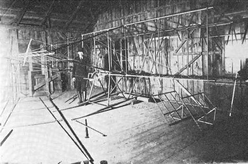
The skeleton of Zalewski's W.Z.T biplane in the Milanowek theatre hall in 1913, with the designer standing beside the machine.
Zbieranski and Cywinski Biplane
Zbieranski's book O narodzinach lotnictwa polskiego (About the Birth of Polish Aviation), already referred to at some length under the 'Czeslaw Tanski' heading, was devoted mainly to the development and description of the Zbieranski and Cywinski biplane, which was built in 1910-11 in Warsaw. Unfortunately the history of this interesting project, as told by Zbieranski, having his memory as the only source of reference, is at variance with the known facts. The book established one valid point, however: namely that Tanski was in no way connected with the development of the Zbieranski and Cywinski biplane, as erroneously suggested in interwar publications and repeated by several writers, including the author of this work in some of his early articles, after the war.
According to Zbieranski's own account, at one of the meetings of the Aviators' Circle in Warsaw, held after the 'first demonstration in Poland of a heavier-than-air machine and its attempts at flight, which took place in the summer of 1909' and was undertaken 'by the French pilot Guyot on the Bleriot Cross-Channel Type' (p. 8 of Zbieranski's book), someone suggested that one of the Circle's members should build an indigenous Polish aeroplane. Zbieranski took up the challenge and went abroad to get acquainted with current design trends. Upon his return, he outlined to the Circle a proposal for a tractor biplane constructed of ash and based upon the 40 hp E.N.V. eight-cylinder vee engine driving a Chauviere airscrew. One of the members, Edward Krzeminski, the owner of a lamp factory, offered to buy the engine, and Zbieranski, having this most expensive item assured, decided to construct the aircraft and went abroad again to purchase the necessary materials.
Zbieranski went first to Paris, where he saw a Voisin biplane built from steel tubes. The simplicity of this solution appealed to him greatly and induced him to change his design from wood to steel tubing. He travelled to Germany and purchased from Deutz a selection of cold-drawn steel tubes, which were not yet on the market. When Zbieranski returned to Warsaw, Krzeminski backed out of his promise to supply the engine, only helping him to hire a shed next to his factory in Solec Street and letting him use his workshop machinery after working hours. Lacking funds for the engine, Zbieranski took a partner with capital, Stanislaw Cywinski, whom he 'immediately despatched to Paris' to purchase the selected French-built E.N.V. engine (p. 12). 'After a few months of disagreeable work in the shed at 103 Solec Street, where rain water poured down on [my] head', he moved the fuselage framework to Hangar No. 1 of the Aviata factory.
Writing on p. 13 about another candidate for the partnership, Mieczyslaw Glowacki, who shortly left the enterprise, Zbieranski stated that in the spring of 1910 the work on the aeroplane was already being done in the hangar and 'the engine and all materials' were delivered, and on pps. 14 and 125 that his 'partner and friend Stanislaw Cywinski did not hold out to the end' in construction of the aircraft. According to p. 20, the building of the machine was finished in the early autumn of 1910, the first unofficial test took place in the autumn of 1910, and the first official test, in public, in the summer of 1911.
So much for Zbieranski's post-war revelations; now let us look at facts. The 'first demonstration in Poland of a heavier-than-air machine and its attempts at flight' took place on 15-19 September, 1909, the pilot and aircraft involved being Georges Legagneux on a Voisin biplane (the second was Baron de Caters also on a Voisin), and not Guyot. Guyot displayed his Bleriot in Warsaw only at the beginning of April 1910, and even borrowed the Anzani engine from Tanski, because his own engine developed trouble (see contemporary press reports in Swiat, Kurier Warszawski, Lotnik i Automobilista, etc). Even if it could be accepted that Zbieranski forgot the name of the pilot and had the first demonstration in mind, the meeting of the Circle was held some time after that and later Zbieranski went abroad.
This means that the study for the aircraft proposed by him could have been conceived only in the winter of 1909-10 at the earliest (by which time Tanski, Libanski and other Polish pioneers were already hard at work on their aeroplanes). Then Zbieranski went abroad again to examine more aircraft and search for materials (to France and Germany), which had to be delivered to Warsaw, and this took time. It took him 'a few months' to build the fuselage at the Solec Street shed. In fact he could not possibly have moved to Aviata earlier than September 1910, because the hangars had not been finished. Tanski was offered accommodation in one of the hangars as soon as they were ready and moved in without delay on 8 October, 1910. By this date only two of the eight hangars were occupied, one of them, No. 1, by Zbieranski. and these apparently went into use only a few weeks, if not days, earlier. Writing to his son Tadeusz, who was studying in France, Tanski said in a letter of 9 October. 1910: 'Zbieranski is doing absolutely nothing, he has no room and no money for the engine'; and later, in a letter dated 10 November, 1910: 'At Zbieranski's (hangar) work is going on in spite of the cold, Cywinski works most.' This contemporary private correspondence establishes three points: that in the late autumn of 1910 the Zbieranski and Cywinski biplane was far from being ready; its designers were still without the engine; and Cywinski was working on the airframe before he went for the engine.
While Cywinski was alive (he was killed by a German shell in September 1939, while fighting the fires of burning Warsaw), Zbieranski described his participation in the project rather differently. During an interview with a reporter from Ilustrowany Kurier Codzienny, published on 17 July, 1938, he stated: 'As a partner and companion in my work I invited Ing Stanislaw Cywinski. We had great difficulties in our work, because the price of materials which were not yet on the market, or not even in existence, could not be estimated... The whole of the aircraft was made with my own and Cywinski's funds.' This clearly proved that Cywinski was closely associated with the development of the project before Zbieranski purchased the steel tubes from Deutz and before the actual construction of the machine began. That the financial considerations in inviting Cywinski 'as a partner' were not the only ones becomes apparent from the fact that towards the middle of 1910 Zbieranski bought for himself the Bleriot Type No. XI monoplane, which was previously used by Pierre Grand, the French pilot giving flying demonstrations in Poland.
Stefan Kozlowski, designer of the first Polish aircraft to leave the ground, in Warsaw, wrote as follows to the author of this work on 30 January, 1961: 'Ing Cywinski visited me in my hangar a few times (in the late spring of 1910) bringing with him some drawings of his aircraft project; we discussed this subject and I shared with him the experience which I had already acquired in this field. It looked to me as if he was evolving the design alone. At this period I did not know Zbieranski.' Similar statements were made by members of the Cywinski family and his surviving friends, who confirmed that Cywinski was passionately absorbed in the preparation of the design and drawings for the biplane, on which he apparently worked alone.
In view of these conflicting statements, the question as to who was really the designer of the biplane will presumably always remain a matter of controversy. However, while it is possible that the initiative to develop the aircraft and its initial sketches did originate with Zbieranski, a businessman who throughout his life showed great interest in various engineering enterprises, there can be no reasonable doubt that Cywinski, who remained an aircraft designer until his death, was involved in the project right from its inception and played a substantial and vital part in the development of the design. The available evidence also establishes that the project was evolved in the spring of 1910, the fuselage built at Solec Street in the summer, presumably during June-September 1910, and the machine completed about a year later, in the spring of 1911.
Zbieranski mentioned more than once in his book the 'unofficial' flight attempt, but discreetly omitted the identity of the pilot involved and any details regarding the results of the trial. In fact, the test, which presumably took place in May 1911 (according to Zbieranski, after the Lodz Aviation Exhibition, where his E.N.V. engine was shown), was made by none other than Stanislaw Cywinski. There are confused reports as to what really happened during that attempt, Zbieranski disclosing only that the biplane 'received minor damage because of a fire which resulted from faulty connection of the cables'. A number of eye witness reports (including the testimony of Karol Milobedzki, prepared specifically for Zbieranski's book and printed there on p. 27) clearly indicated that the aircraft made on that occasion a short flight which ended in a minor mishap. Again, contrary to Zbieranski's statements (pps. 14 and 125), the fact "that Cywinski worked on the machine right until its final completion and test is beyond dispute. Indeed, Zbieranski himself, somewhat shattered by the hot reception which his book received in Poland, admitted this in his article in Skrzydlata Poiska in 1960 (Nos. 43 and 44).
The first wholly successful flight of the Zbieranski and Cywinski biplane was carried out from Mokotow aerodrome by one of the best-known and respected pilots, Michal Scipio del Campo. According to Zbieranski this unfortunate take-off for Moscow' and his aircraft thus became 'the second flying prototype of steel in Europe and the first Polish aeroplane to meet all the principles required from the heavier-than-air machine, i.e. which could freely take-off from the ground and be freely controlled by man in the air' (p. 23). It is easy to establish from the study of contemporary materials that 'Scipio del Campo's unfortunate flight' (to Petersburg and not to Moscow) began on 26 September, 1911. The Zbieranski and Cywinski aircraft was therefore tested on 25 September (in any case Scipio del Campo began to fly in Warsaw only on 13 August, 1911, and this test was made some weeks later).
Apart from the Polish designs evolved abroad (Warchalowski Wrobel), the Zbieranski and Cywinski biplane was not the first Polish aeroplane to make a sustained and controlled flight. Libanski's Jaskolka, built in Lwow and tested in Wiener-Neustadt, successfully flew in August 1911, and the Glowinski monoplane, built and flown in Tarnopol, achieved a similar distinction sometime in the spring of 1911. Sensing the challenge to his claim from the Jaskolka, Zbieranski eliminated it with an astonishing fabrication that the machine was the work of 'an Austrian' (see Jaskolka). The Glowinski monoplane was not favoured with any mention in his book. Furthermore, the biplane was not 'of steel', but of composite construction, only its fuselage being of steel tubing, and this was not uncommon (Libanski built a steel fuselage a year earlier).
The September flight of the Zbieranski and Cywinski biplane was a complete success. The machine circled Mokotow aerodrome four times, covering a distance of 15-20 km (9.3-12.4 miles) at a height of 50-60 m (164-197 ft) and achieving a speed of about 70 km/h (43.5 mph). Michal Scipio del Campo described the test as 'exceeding his expectations'. The biplane 'took-off at the first attempt, was manoeuvrable, fast, and docile in landing. It had ... some minor, easily curable, shortcomings, i.e. indicated a tendency to drop its nose. Its main fault was the unsuitable engine, too heavy and weak for its own and the aircraft's weight.' As the designers did not have another powerplant, Scipio del Campo offered to lend the 50 hp Gnome rotary from his Morane monoplane. The engine was installed in the biplane, but Scipio del Campo recollected: 'circumstances beyond my control prevented me from making a test flight with this new engine... This I regret even now, as results could have been outstanding.'
In the autumn of 1911, because of misunderstandings arising from financial arrangements, and presumably also from disagreements regarding the use of the aircraft (Cywinski, inexperienced as a pilot, was believed to have been stopped by Zbieranski from further flight attempts), Cywinski decided to withdraw from the partnership. As Zbieranski was unable to repay Cywinski's share, the latter accepted the E.N.V. engine, which he sold to someone for installation in a motorcar. Towards the end of the year the Aviata factory required its hangar No. 1 for its own use and asked Zbieranski to vacate it. Having nowhere to go, Zbieranski offered his aircraft to ZASPL and in 1912, at ZASPL initiative, the engineless machine was transported by rail from Warsaw to Krakow. The biplane was displayed in Krakow for a long time in order to raise funds for its upkeep and transport to Lwow. However, it never left Krakow and was completely burned out in the first days of World War 1 when the building in which it was stored was accidentally set on fire.
The aircraft in question was outstandingly advanced in overall concept and design and the most successful among the machines constructed in Poland at that time. It was also the first Polish aircraft to achieve a fully sustained and controlled flight in Poland's capital city. On these grounds it should have a lasting place in the history of Polish aviation.
In view of the conflicting evidence as to who really designed the biplane, any honest historian must allot the credit equally between Cywinski and Zbieranski. The author decided to retain the designation 'Zbieranski and Cywinski Biplane', as this was used in most contemporary publications, Zbieranski's name being then mentioned first because of his handling of all commercial transactions (such as purchases of materials, hiring of the shed and hangar, etc) associated with the building of the machine.
Construction: The Zbieranski and Cywinski aircraft was a single-seat unequal-span two-bay biplane of composite construction. The wings, with a total area of 31 sq m (333.7 sq ft), were conventional wooden frameworks of double-surfaced type, and the interplane struts were of steel tubing. The lower wing, with a span of 9 m (29 ft 6 3/4 in), featured slight dihedral, the interplane gap reducing from 1.85 m (6 ft 1 1/4 in) in the centre to 1.6 m (5 ft 3 1/4 in) at the tip. Chord of the top wing was 1.75 m (5 ft 9 in) and of the lower wing 1.6 m (5 ft 3 1/4 in). Ailerons were fitted only to the upper wing. The open fuselage frame, of triangular section, was built up of cold-drawn steel tubes, the smaller diameter tubes being filled with solid wood for strength. No welding was used, the whole frame being assembled with the help of connecting joints and steel screws. The pilot's position, behind the engine, was provided with a conventional control stick and rudder bar. The tail unit, of biplane configuration and structure similar to that of the wings, embodied full-chord tip elevators and twin rudders. The landing gear, incorporating special rubber shock-absorbers, consisted of two wheels and two skids, the skids being lowered on first contact of the wheels with the ground and supporting the machine during landing. Power was supplied by the E.N.V. Type D eight-cylinder upright vee water-cooled engine developing 40 hp at 1,700 rpm and driving the 2.25 m (7 ft 4 3/4 in) diameter Chauviere airscrew. The whole airframe could easily be dismantled into four major sections for transport. Dimensions included a span of 10 m (32 ft 9 3/4 in) and length of 8.5 m (27 ft 11 in). The loaded weight was 340 kg (749 lb).
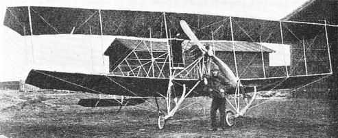
Zbieranski and Cywinski biplane, ihe most promising machine among early aircraft constructed in Poland, which successfully flew in September 1911.
S.Z. Quadruplane Nos. 1 and 2 (Zalewski W.Z.III and IV)
When World War 1 broke out Wladyslaw Zalewski joined the Imperial Russian Air Service and was eventually posted to the 2nd Aircraft Park at Warsaw. The head mechanic there, Vladimir Savieliev, who had previously worked on the assembly of the famous 'giants' Ruski Vitaz and Ilia Muromets at the Russo-Baltic Wagon Works, gave much thought to the problems associated with construction of large aircraft and came to the conclusion that such aeroplanes should have five or six wings, since by this means overall dimensions and structural weight could be appreciably reduced and the efficiency of the design improved. In the summer of 1915 Savieliev, who had no design experience, asked Zalewski to prepare a study for a multi-plane heavy bomber.
As a first step, the Pole suggested the development of a small single-engine quadruplane. This was agreed upon and in November 1915, the project - known, from the names of Savieliev and Zalewski, as the S.Z. Quadruplane No. 1 - was submitted to the C-in-C of the Air Service for approval. Development was authorized immediately and construction was undertaken by the workshops of the 2nd Aircraft Park, which had by then moved to Smolensk. To speed up the building of the machine, parts from other types of aircraft were used, including a Morane G's engine bearers, cowling, flying controls, wheels and elevators (a Morane elevator was also used to serve as the rudder), various Farman fittings and the tailskid of a shot-down Albatros. So that the quadruplane could be used either as a single- or two-seater, the observer's cockpit was located at the C.G., in front of the pilot's cockpit.
Taxi-ing trials began on 23 April, 1916, with Col Jungmeister at the controls. On one of the first runs the machine lifted itself into the air unexpectedly and so the pilot carried on to make a very successful first flight. Manoeuvrability proved to be exceptional (the quadruplane could turn inside a Nieuport Bebe fighter) and the handling qualities delightful. Col Jungmeister, highly impressed with the machine, requested its immediate release for reconnaissance duties, but Zalewski, intent on improving its performance, obtained official permission to carry out extensive modifications and developed the aircraft into the S.Z. Quadruplane No. 2, which began tests in October 1916.
As modified, the machine featured redesigned increased-span wings with less camber and a reduced angle of incidence. A more powerful, 100 hp Gnome Monosoupape rotary was fitted and the observer was provided with a light machine-gun, installed on a pyramid structure in front of the forward cockpit and arranged to fire above the airscrew. Trials indicated improved all-round performance and manoeuvrability, even better than that of the earlier model. Early in November 1916, the S.Z. Quadruplane No. 2 was delivered to the 4th Squadron, 4th Wing of the Imperial Russian Air Service, based near Mir in the Baranowice region, at the request of Col Jungmeister who was its CO.
Its operational career was rather short. After a few reconnaissance sorties, Jungmeister was forced down when his engine seized up over enemy lines. Landing in the immediate vicinity of the front, the pilot did not notice field telephone cables, and the machine struck them on touchdown and nosed over. Its white-painted underside attracted the attention of German aircraft, which attacked the field and dropped a few bombs. In spite of all this, the quadruplane was not seriously damaged. It was taken for repairs to Lebedev factory in Petersburg, but because of the revolutionary disorders of the time these were never carried out. For the same reason plans for quantity manufacture of the type never progressed beyond the first aircraft. Later Zalewski allocated to the S.Z. Quadruplane Nos. 1 and 2 the numbers W.Z.III and IV respectively in his personal designation sequence.
The quadruplane story has an interesting postscript. In 1959 the Frunze Central Aviation House in Moscow received certain material regarding the S.Z. aircraft from Savieliev, who claimed to have been mainly responsible for the design of the machines. He stated that they were known from his own initials as the SV quadruplanes. However, the photographs of the aircraft available to the author distinctly show the letters S.Z. (in the Russian alphabet) on the engine cowling. After the war Savieliev evolved a modified copy of the S.Z. Quadruplane No. 2, which was completed in Russia in 1923.
Construction: The S.Z. No. 1 and No. 2 were two-seat diminishing-span single-bay reconnaissance quadruplanes constructed of wood except for the tail unit. The wings of the Quadruplane No. I, with 18 deg stagger and a gross area of 24 sq m (258.3 sq ft), were two-spar fabric-covered structures, the spars being of the hollow, laminated variety. Based on Prof Bauman's theories, they employed the arch-type aerofoil section with deep undercamber and had 4 deg of incidence. The diminishing wing panels were connected by two pairs of parallel interplane struts of solid pine on either side. The bottom wing, spanning 5.5 m (18 ft 0 3/4 in), had up-turned tips. Hinge-mounted ailerons, operated by cables, were fitted to the two upper wings only. In order lo facilitate access to the cockpits, the centre section of the second wing from the top was not covered and was free of ribs, small fences flanking the gap. The S.Z. Quadruplane No. 2 featured increased-span wings of less cambered aerofoil section, which had an area of 26 sq m (279.9 sq ft) and incidence of 3 deg. In all other respects its wings were essentially similar to those of the earlier model.
The fuselage was a wire-braced wooden box-girder structure covered with three-ply and accommodated two seats in tandem, the pilot's cockpit, at the rear, being slightly raised. The monoplane tail unit consisted of a welded-steel tubular frame with fabric covering, and incorporated a braced tailplane and unbalanced rudder and elevators. The landing gear consisted of a through axle, attached by rubber cords to tubular-steel Vs on either side of the fuselage. The S.Z. No. 1 was powered by a partly-cowled 80 hp Gnome seven-cylinder rotary engine, driving a two-blade tractor airscrew which was designed by Zalewski to Stefan Drzewiecki's theories. The S.Z. No. 2 was equipped with the 100 hp Gnome Monosoupape seven-cylinder rotary, which drove a new Zalewski airscrew.
Overall dimensions of the S.Z. Quadruplane No. 1 included a span of 8.5 m (27 ft 11 in), a length of 6 m (19 ft 8 1/4 in) and a height of 3.3 m (10 ft 10 1/4, in). Empty and maximum loaded weights were 360 kg (794 lb) and 660 kg (1,455 lb). Performance included a maximum speed of 115 km/h (71.5 mph). The S.Z. Quadruplane No. 2 had an overall span of 9.3 m (30 ft 6 1/4 in), its length and height remaining the same. The maximum loaded weight rose to 750 kg (1,653 lb) and maximum speed to 135 km/h (83.9 mph).
S.Z. Quadruplane No. 3 (Zalewski W.Z.V)
In September 1916, Savieliev was issued with the War Department specification for a three-seat army co-operation reconnaissance bomber with a 220 hp engine, either Renault or Salmson, a useful load of 550 kg (1,213 lb) and a maximum speed of not less than 140 km/h (86.9 mph). Wladyslaw Zalewski immediately began studies for the required machine, selecting the 220 hp Renault eight-cylinder upright vee water-cooled engine in preference to the Salmson radial. The new project, originally known as the S.Z. Quadruplane No. 3 and retrospectively designated the W.Z.V, was a larger and heavier derivative of the previous S.Z. models.
The study, prepared in Smolensk, was completed in February 1917, and a prototype was to be built in Kiev, but due to the German advance towards that city it was necessary to transfer this work deeper into Russia. At that time Zalewski met one of the organizers of the Central Experimental Aerodrome in Kherson on the Black Sea who became very interested in the design and offered to construct the machine at this new establishment. Preliminary work on the prototype was being undertaken in the early spring, but revolutionary troubles soon brought it to a complete halt.
In the winter of 1916-17 Zalewski evolved proposals for a giant heavy quadruplane bomber designed around four 215 hp Sunbeam Arab or 220 hp Renault water-cooled engines. The aircraft, designated the W.Z.VI, was to be heavily armed with Scarff-mounted machine-guns and able to carry up to 700 kg (1,543 lb) of bombs, its estimated empty and maximum loaded weights being 4,500 kg (9,920 lb) and 7,000 kg (15,432 lb). It was intended to build a prototype in the workshops of the Central Experimental Aerodrome at Kherson, but this plan also came to nothing because of the revolution.
Construction: The S.Z. No. 3 was a three-seat diminishing-span single-bay reconnaissance bomber quadruplane of wooden construction. The wings, with a total area of 60 sq m (645.8 sq ft), were aerodynamically and technologically larger replicas of those of the previously described S.Z. Quadruplane No. 2, except for the bottom wing, with a span of 8.8 m (28 ft 10 1/2 in), which dispensed with the up-turned tips. All wing panels were of equal, 1.3 m (4 ft 3 1/2 in), chord and the interplane gap was 1.2 m (3 ft 11 1/2 in). The ply-covered fuselage accommodated two side-by-side seats with dual controls for two pilots, with a fixed synchronized gun on the port side, and the observer's cockpit with a Scarff ring for a single or twin Lewis gun behind. Zalewski originally intended to place the fuselage between the two lower wings, but later abandoned that idea, settling for a layout similar to that of the earlier S.Z. Quadruplanes, and except for the main landing-gear units, which featured twin wheels, the machine was in all other respects basically similar to those aircraft. Overall dimensions included a span of 148 m (48 ft 6 3/4 in), a length of 9.2 m (30 ft 2 1/4 in) and a height of 4.6 m (15 ft 1 1/4 in). Estimated empty and maximum loaded weights were 1,180 kg (2,601 lb) and 1,750 kg (3,858 lb) respectively, and wing loading 29.2 kg/sq m (6 lb/sq ft). Estimated performance in the fully loaded condition included a maximum speed of 148 km/h (91.9 mph) at sea level and 140 km/h (86.9 mph) at 2,000 m (6,561 ft), and a service ceiling of 3,700 m (12,139 ft).
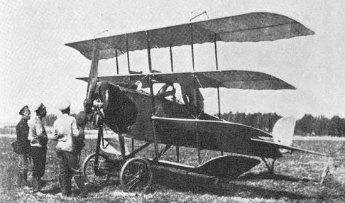
The S.Z. Quadruplane No.1 (W.Z.III) with 80 hp Gnome rotary engine during early tests at Smolensk in the spring of 1916.
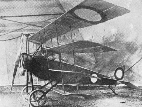
The S.Z.Quadruplane No. 2 (W.Z.IV) in a tent at Mir, while operating with the 4th Squadron, 4th Wing, Imperial Russian Air Service, in November 1916.
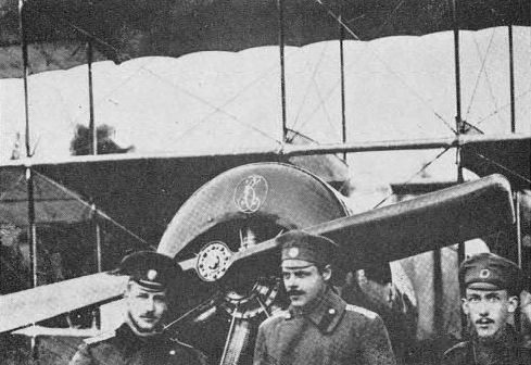
Right to left: Wladyslaw Zalewski, Vladimir Savieliev and Col Jungmeister, in front of the S.Z.Quadruplane No. 1. The Cyrillic letters S.Z. are clearly visible o n the engine cowling.
Bronislawski System Aircraft
In the years 1910-11 Boleslaw Bronislawski, a Polish doctor of science working in France, invented a new method of control for aircraft, called the Bronislawski stabilizing system, which was claimed not to infringe any Wright patents and to offer substantial advantages over the conventional concept. Concentrating mainly on the development and perfection of his novel control system, Bronislawski decided to test it first on existing aircraft rather than on a machine of his own design and selected Henri Farman biplanes for this purpose.
His first machine was a modification of the Farman lifting-tail biplane with front elevator. The aircraft was adapted to incorporate the early version of the Bronislawski stabilizing system, which consisted of five stabilizing planes on each side, and was successfully tested at Juvisy near Paris around the middle of 1911, the trials being conducted by the designer's brother, who helped generally to perfect the system. This aeroplane represented only the interim experimental medium intended to try out the overall feasibility of the idea and confirm findings of the theoretical research, its wings retaining the original ailerons as the secondary means of lateral control.
Bronislawski's second aircraft was a conversion of the Farman Racing Type of 1911 with a 50 hp Gnome seven-cylinder rotary engine and embodied the revised and improved Bronislawski stabilizing system, which incorporated only two stabilizing planes on each side. In view of the encouraging results with the earlier type, the later machine completely dispensed with ailerons, relying entirely on the new method of control. This Gnome-powered model, completed in the autumn of 1911, was displayed at the 1911 Exposition Aeronautique in Paris, featuring fabric covering over the extensions of the top wing, which were originally left uncovered. The machine was extensively tested in 1912 and in the autumn of that year was re-engined with the novel 65-70 hp Burlat eight-cylinder rotary air-cooled engine.
The Bronislawski stabilizing system could be used not only on biplanes but on aircraft of all types and configurations, and in 1912 a special company was formed for the promotion and production of aeroplanes with Bronislawski controls. However, the sponsors of the venture apparently failed to convince prospective customers of the advantages of the new system, and the interesting idea eventually vanished into obscurity.
As exemplified by the second aircraft, the Bronislawski stabilizing system consisted of a pair of cambered planes, each 1.5 m (4 ft 11 1/2 in) long and 0.45 m (1 ft 6 in) deep, which were set at a positive angle of incidence and rigidly mounted on a rotating vertical steel-tube mast supported from the front and rear spars of the top and bottom wings by skeleton extension pieces of oval steel tubing. One of these units was situated at the end of each outer wing bay.
In normal flight these supplementary planes were arranged in end-on aspect to the relative air flows, but as soon as the machine was tilted out of the horizontal in a lateral sense, these planes were rotated about their vertical axes by means of wires passing from the pilot's control lever to a drum attached to the bases of their respective masts. By their rotation, the planes became incident to the relative wing and thus lifted or depressed according to whether their incidence was positive or negative. Both sets of planes at either end of the main supporting surfaces worked in conjunction, thus forming a righting couple. One of the most important features of the system was that in the action of restoring balance the position of the centre of resistance of the machine as a whole was not altered, so that there was no need to bring the rudder into action.
Bronislawski stabilizing planes combined the functions of ailerons and elevator. The system was claimed to be very easy to operate and to make flying much simpler, the movements of the control lever being adapted to the instinctive reactions of the pilot's body to maintain balance.

The first Bronislawski conversion of a Farman biplane with the early Bronislawski stabilizing system, comprising five stabilizing planes on each side,
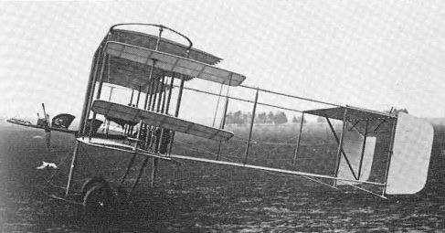
The second Bronislawski system aircraft, with two stabilizing planes on each side and a Gnome rotary engine.
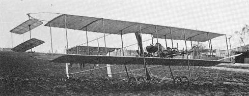
Previously unpublished view of the second, Gnome-powered Bronislawski system aircraft during tests in 1912.
Drzewiecki's Aircraft
Stefan Drzewiecki, grandson of a Polish Napoleonic legionary (born in Kunka in Podole on 26 December, 1844), holds a unique place in the history of aeronautics as the first Polish aviation theorist and scientist of international standing. A brilliant and versatile railway and marine engineer with various inventions and pioneering work in the field of submarine development to his credit, he became one of the principal contributors to the early art of aviation science and exercised a profound influence upon the shaping of ideas on heavier-than-air flying machines. Although some historians credit him with the design of an 'aerovelocyped' (or aerovelocipede), which was a muscle-powered helicopter-type device with two airscrews, in 1875, there is no documentary evidence in existence to connect him with such a machine.
His documented aeronautical activities date back to the early 1880s. In 1882 he was elected to the post of vice-president of the Aerial Navigation Branch of the Tsarist Russian Technical Association in Petersburg, and in a lecture on the theme of dynamic flight, delivered to that association on 13 April, 1885, Drzewiecki put forward his theory on the subject. During the same year he began to publish scientific articles, treatises and books, mainly in Russian and French, which expanded and explained his theory of flight and contained very advanced and original thoughts and observations. He declared himself against the lighter-than-air class of designs and decisively in favour of a fixed-wing aeroplane (as opposed to ornithopter and helicopter-type aircraft), advocating such a machine as the most efficient and rational type of flying device. In his book Aeroplany w prirodie (Aeroplanes in Nature), Petersburg, 1887, he set out the idea of an aeroplane provided with an engine and airscrew. During the same year he repeated his views in Paris, causing a major controversy and gaining the friendship of such pioneers as Chanute, Mayer and Mouillard, whose ideas largely coincided with his own.
Drzewiecki's greatest contribution to the development of aviation was his pioneering work in the field of airscrews. His airscrew theory, sometimes known as the Drzewiecki Elemental Blade Theory, which was published in its initial form in Petersburg and Paris in 1892, became the first comprehensive, scientific work on the subject and described, for the first time in world technical literature, practical methods of mathematical calculations for the design of airscrews. His original airscrew theory, later amended and supplemented by him and other scientists and better known as the Froude-Drzewiecki general airscrew theory, was closely studied by such pioneers as Chanute and the Wright brothers, providing one of the foundations of modern aeronautics. Extensive research in this field led Drzewiecki to the publication of his classic major works Des Helices Aeriennes (Paris, 1909) and Theorie Generale de l'Helice (Paris, 1920).
Quantity manufacture of airscrews to Drzewiecki designs was undertaken by Pierre de Ratmanoff Compagnie of Paris, in 1909, these being marketed throughout Europe under the trademark Helice Normale. The Normale airscrews were used by a number of great pioneers, including Bleriot, Illner (Taube), Labouchere, Latham (Antoinette) and Paulhan, and several world records and outstanding nights were accomplished on aircraft equipped with them. After the war, during the years 1926 to 1929, Drzewiecki developed a constant-speed airscrew, which was made in prototype form.
Drzewiecki understood better than most people the need for scientific research in aeronautics and in 1909 launched a public campaign, writing a booklet and various articles calling for the creation of extensive aviation laboratory and research facilities. He advocated that wind-tunnel experiments should form the basis for all the work in this field and outlined proposals and designs for such a tunnel. His appeals met with good response, Count Henri Deutsch de la Meurthe subscribing the equivalent of some $10,000 towards the provision of such research facilities, and helped to speed up the completion of the famous St Cyr Aerodynamic Institute.
In the first years of the 20th century Drzewiecki showed increasing interest in the problem of aircraft stability and flight safety. Inspired by Joessel Law in hydrodynamics, he adapted Law's theories to aerodynamics, and an extensive study of the relationship between the wing incidence and the centre of pressure and gravity led him to ideas for automatically-stable aircraft. In France, in December 1909, and March 1910, he patented his first proposals for such a machine. As a result of further theoretical and practical investigations, he developed completely revised proposals for an automatically-stable aeroplane later in 1910. The Drzewiecki automatic (or natural) stability principle in its ultimate form was based upon the utilization of the difference in air pressure arising from the employment of different aerofoil sections in a design of tandem-wing configuration.
The machine's smaller and more lightly loaded, movable front wing was of a specially developed Eiffel aerofoil section (No. 8), in which the lift increased comparatively slowly between 5 deg and 18 deg, the lift coefficient being 0.058 and normal angle of incidence 8 deg, whilst the larger fixed rear wing was of conventional section (Eiffel No. 13bis or Bleriot XIbis), having a lift coefficient of 0.041 and being set at an angle of 5 deg. Loading of the front wing was in the region of 40 kg/sq m (8.2 lb/sq ft) as against the 22 kg/sq m (4.5 lb/sq ft) of the rear wing. Thus, when the equilibrium was disturbed and the aircraft became tail down, the lift of the rear wing increased more rapidly than that of the front wing and a restoring couple was set up. Conversely, in a dive, the lift of the rear wing decreased more quickly and produced a restoring couple in the opposite sense. In this way longitudinal stability was maintained automatically, and climb and descent could be effected by an increase or decrease in the engine power, without the pilot touching the flight controls. In addition, exceptional safety was claimed for the aircraft, which, with the C.G. in the centre between the two wings, could not nose-over during landing and was as stable on the ground as in the air.
The selection of the most suitable combination of wing sections was made after protracted wind-tunnel experiments in the Eiffel aerodynamic laboratory, which were conducted in 1910 and 1911. A 1:10 scale-model of the machine underwent further wind-tunnel tests with particular reference to its reaction to C.G. movements and changes in the angle of incidence of the wings. The Drzewiecki tandem-wing monoplane was therefore one of the world's first designs to undergo comprehensive wind-tunnel trials. The aircraft, constructed in the Pierre de Ratmanoff factory in Paris, was completed in the autumn of 1912 and shown on the Ratmanoff stand at the 1912 Exposition Aeronautique in Paris. The machine, powered by a 70 hp Labor four-cylinder inline water-cooled engine, which was installed in the fuselage and drove a pusher two-blade Drzewiecki airscrew with a diameter of 2.6 m (8 ft 6 3/4 in) via an extension shaft, was universally acclaimed as the only real novelty and the most interesting design in the show.
After some slight alterations to the landing gear, the aircraft began flight trials at Chartres airfield early in 1913 and proved satisfactory from the outset. In the course of the year the machine made several flights during which it fulfilled the designer's expectations and perfectly maintained automatic stability, fully confirming that Drzewiecki's principle worked in practice exactly as anticipated. However, because of the troublesome powerplant, which was liable to malfunction, pilots did not like flying the machine, and the designer, then already 69, could not fly it himself.
In view of the engine difficulties and the fact that the weight of the airframe considerably exceeded the original estimate, the inventor began research on an improved, lighter development of the basic design in the latter part of 1913. He intended to submit this aeroplane for the design contest for the safest aircraft. The new project differed from its predecessor principally in having a more powerful 80 hp Gnome Monosoupape seven-cylinder rotary engine, which was mounted at the rear of the fuselage, obviating the need for an extension shaft, and its front wing was moved higher up and attached above the fuselage to a steel-tube cabane. A number of minor structural and aerodynamic refinements were also introduced. The machine had an overall span of 9 m (29 ft 6 3/4 in) and its total wing area was 24.9 sq m (268 sq ft), 16.4 sq m (176.5 sq ft) for the rear and 8.5 sq m (91.5 sq ft) for the front wing. Its normal maximum loaded weight (as a two-seater and with fuel for 5 hr) was 625 kg (1,377 lb) and estimated maximum speed was given as 110 km/h (68.3 mph). A scale-model of this development was fully tested in the Eiffel wind-tunnel and construction of the aircraft began in the spring of 1914, but nothing is known about its completion. Presumably the outbreak of World War 1 prevented its being built.
Although working abroad, Drzewiecki showed a keen interest in the development of flying in his native country and publicly emphasized his Polish nationality on several occasions. He became an honorary member of the Lwow 'Awiata', helping this association in various ways, and sent his airscrews as exhibits for the First Aviation Exhibition in Lwow in 1910. Remaining in France after the war, where in spite of his age he was still conducting scientific research (his last work being on the kinetic theory of gases), he made a very substantial donation to L.O.P.P. towards the building of the Warsaw Aerodynamic Institute. He died in Paris in April 1938, leaving in his will all his works, scientific documentation and tremendous library to Poland. Unfortunately, they were entirely destroyed in Warsaw during the war. His outstanding contribution to the world of science was widely recognized, and he was honoured by several nations, including Russia, France, Great Britain and Poland, with decorations, diplomas and tributes, among them a Commendation of the Academy of Science in Paris, a British diploma of Naval architecture, and the third honorary membership of L.O.P.P. to be awarded (after the first two awarded to the Polish heads of state. President Moscicki and Marshal Pilsudski).
Construction: The Drzewiecki aircraft was an experimental two-seat wire-braced tandem-wing monoplane of wooden construction. The rear, fixed wing, having an area of 18 sq m (193.8 sq ft) and a chord of 2.4 m (7 ft 10 1/2 in) at the root, slightly tapering towards the tips, was a two-spar double-surfaced structure covered with fabric. It was attached to the upper portion of the rear fuselage and braced by wires to a cabane incorporating the fin and to the fuselage and rear landing-gear framework. It was normally set at a 5 deg angle of incidence, but this could be adjusted on the ground, the limit of adjustment being 3 deg. The front wing, wire-braced to the cabane in front of the pilot's seat and to the front undercarriage members, had a span of 5.6 m (18 ft 4 3/4 in), a constant chord of 1.5 m (4 ft 11 1/2 in) and an area of 8 sq m (86.1 sq ft), the total area of both wings being 26 sq m (279.9 sq ft). Each half of the front wing, a single-spar double-surfaced structure pivoting round a horizontal tube which ran across the fuselage just above its lower longerons, moved independently, being in no way connected with one another. Each half was operated by a which could be adjusted on the ground in accordance with the loading. Acting differentially, the front wing halves assumed the function of ailerons; operated together, they acted as elevators, permitting the pilot to control longitudinal stability, which was otherwise maintained automatically. The fin was mounted centrally over the rear end of the fuselage and directional control was effected by two pivoting rudders, one on each tip of the rear wing. Each rudder was operated independently by a foot pedal and rotated outwards with its broadside towards the direction of flight, forming an air brake.
The fuselage was a rectangular-section structure covered with fabric, except for the underside below the engine, which was covered with sheet metal. Two open seats in tandem, with the pilot in front, were situated at the front of the fuselage, with the fuel and oil tanks in the centre and the engine further aft. The undercarriage comprised two separate units. The front unit consisted basically of two steel-tube side Vs. a cross-axle and a central skid, the upper ends of the rear arms of the Vs being attached to a horizontal oleo-pneumatic shock-absorber which was mounted under the fuselage. On landing, the wheels receded and the central skid came into contact with the ground. The rear landing unit featured two strong wooden trailing skids and two small-diameter wheels on leaf-spring shock-absorbers. All four wheels were additionally sprung with rubber cords. Overall dimensions included a span of 9 m (29 ft 6 3/4 in) and a length of 8 m (26 ft 3 in). Empty and normal maximum loaded weights (as a two-seater and with fuel for 5 hr) were 500 kg (1,102 lb) and 750 kg (1,653 lb). Cruising and maximum speeds were 95 km/h (59 mph) and 105 km/h (65.2 mph).
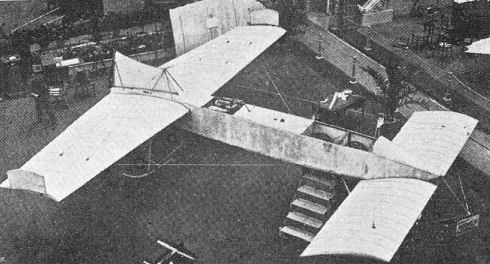
Drzewiecki's Labor-powered tandem-wing monoplane at the 1912 Paris Salon,

Drzewiecki tandem-wing monoplane with the designer in the cockpit at Chartres early in 1913.
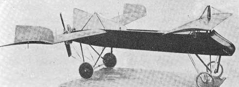
A wind-tunnel model of the improved Drzewiecki tandem-wing monoplane with a Gnome Monosoupape rotary engine, developed for the design contest for the safest aircraft.
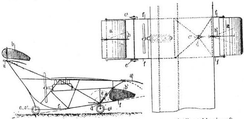
Patent drawings of Drzewiecki's first ideas for an automaticaliy-stable aircraft, December 1909 - March 1910.