
Книги
Putnam
D.James
Westland aircraft since 1915
35
D.James - Westland aircraft since 1915 /Putnam/

D1773, the 57th D.H.4 built by Westland.
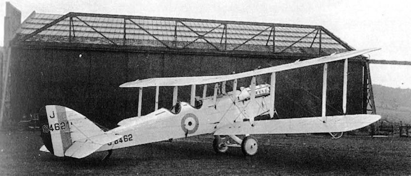
A late production Liberty engined D.H.9A converted to dual trainer by the Westland Aircraft Works at Yeovil in 1928.
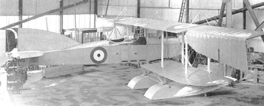
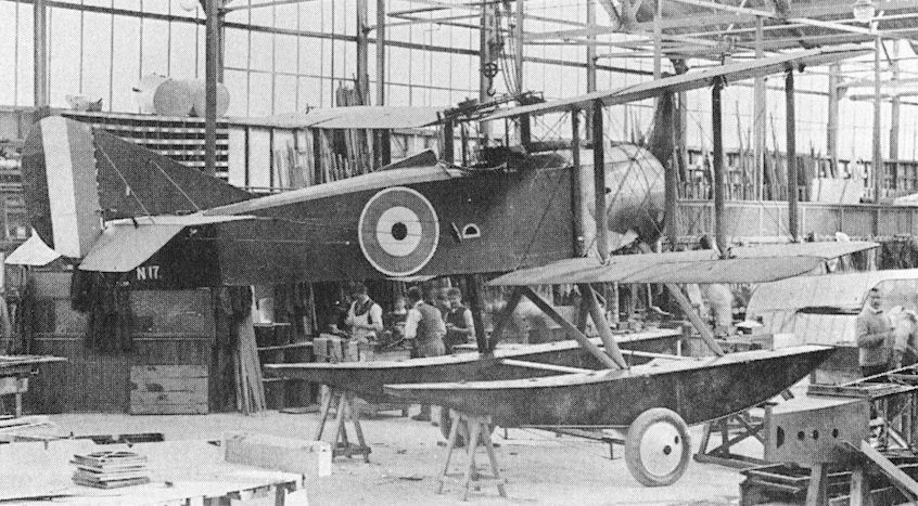
The first Westland-built Short 166 floatplane, 9751, in the Yeovil factory, with the Salmson radial engine of another aircraft visible at the left of the photograph.
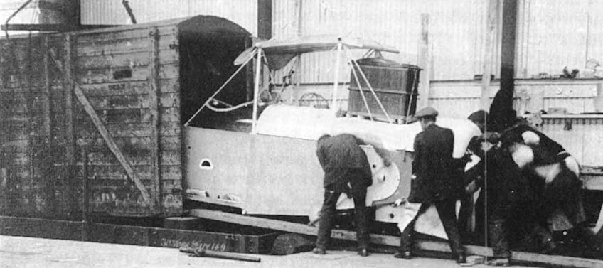
The fuselage of a Short 166 being loaded into a railway wagon in the siding of Westland's despatch department in 1916.

A horse-drawn cart takes Short 166 wings and centre-sections from the factory to Yeovil's Great Western Railway junction.
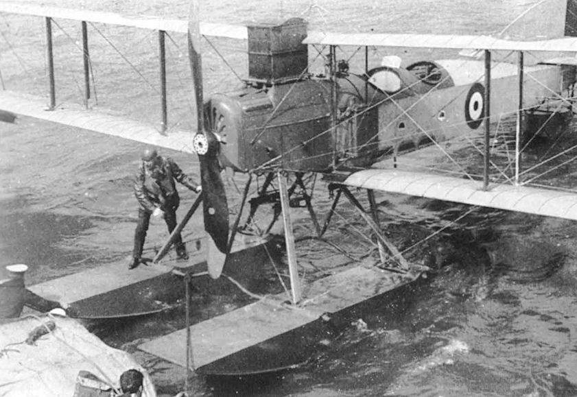
A Short 184 floatplane of the type built by Peller's Westland Aircraft Works during 1915-16.
Sopwith 1 1/2 Strutters being built in Westland's factory in 1916.

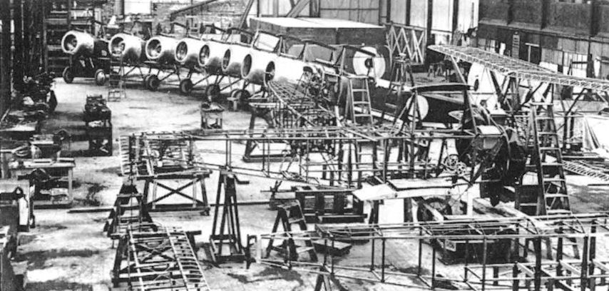
Six Vickers Vimys, with H5080 and H5081 nearest the door of the 140 ft span new 'Vimy hangar' at Yeovil.
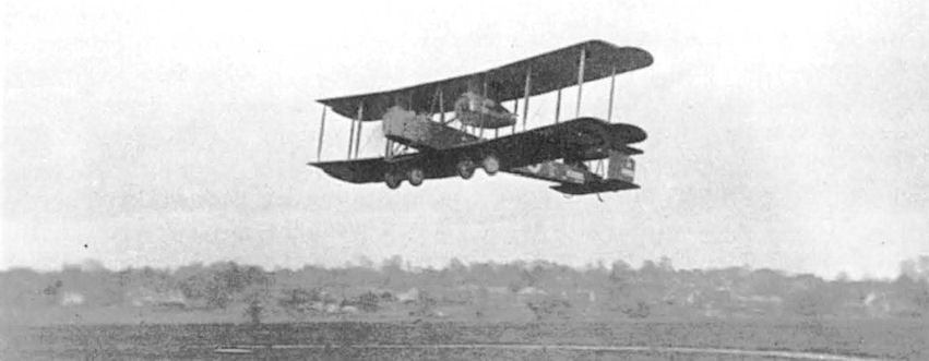
Vimy H5080 taking off from the Yeovil aerodrome.
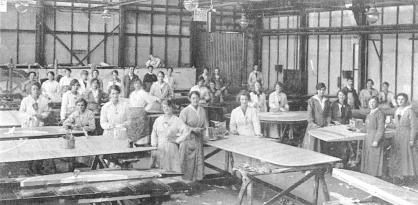
Westland's covering shop where the deft fingers of girl fabric workers were halted for this photograph of Vimy control surfaces being covered.
N.1B
In 1916, with a growing number of Royal Navy ships capable of carrying and launching aircraft with wheeled undercarriages or floats, the Air Department of the Admiralty was examining the potentialities of single-seat fighters. It was also considering the means whereby such an aircraft could be designed and produced to meet naval requirements. Thus the Air Department N.1B requirement was for a single-seat shipboard float plane or flying-boat fighter having a speed of 95 knots (110 mph) at 10,000 ft and a ceiling of at least 20,000 ft. This latter requirement was particularly exacting, bearing in mind the comparatively low power/weight ratios and levels of reliability of the engine available at that time.
Three aircraft manufacturers prepared designs to meet this requirement; they were the Blackburn Aeroplane and Motor Co, the Supermarine Aviation Works and Westland Aircraft Works. Both the Supermarine and Blackburn designs were pusher biplane flying-boats but the other design, the first to emanate from the Westland Aircraft Works, was a more conventional tractor biplane floatplane. Contracts for the construction of a total of eight prototypes, all designated N.1B, were placed with the three companies; three each by Blackburn and Supermarine and two by Westland.
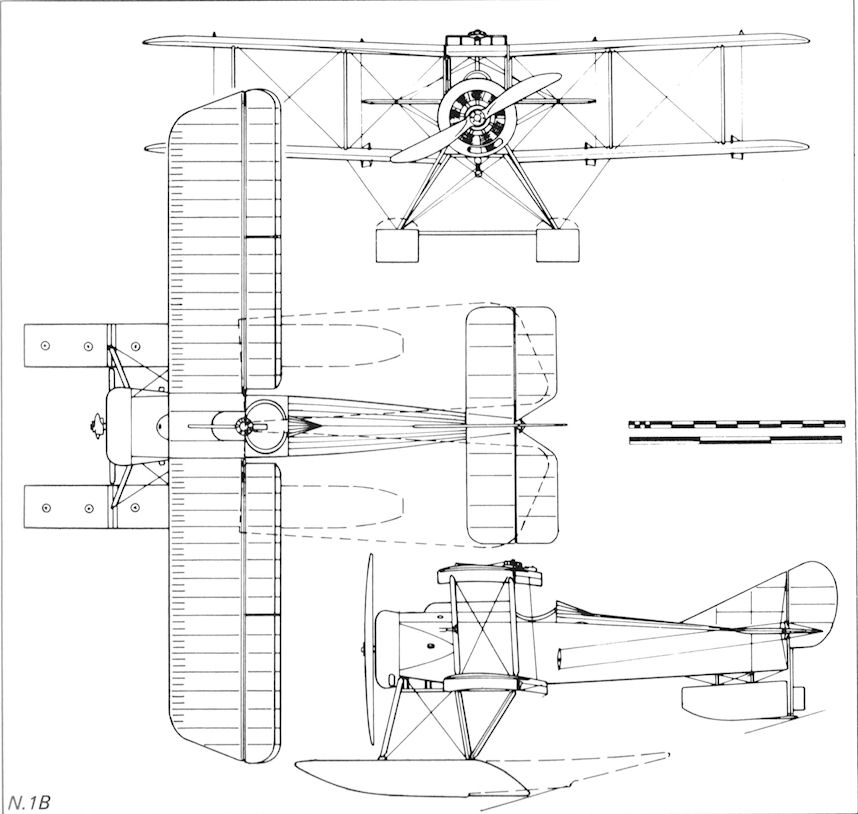
The design of the two Westland N.1B was the work of Robert Bruce and Arthur Davenport, the company's manager and chief draughtsman respectively. The construction, understandably, followed the standard pattern of that era. The fuselage was a conventional rectangular-section structure with four longerons and internal wire-braced frames of spruce with steel end fittings, the front ends of the longerons carrying the mounting for the 150 hp Bentley AR.1 (for Admiralty Rotary) rotary engine. Wooden formers on the upper longerons provided a rounded top surface to the fuselage. The cockpit surround was of leather-edged ply and had a small head fairing. The entire tail unit was an externally wire-braced wooden structure. The constant chord two-bay biplane wings were built up around two ash main spars with wire-braced spruce struts and ribs, and spruce interplane struts. Ailerons and trailing-edge flaps, described as a 'wing camber-changing device patented by Robert Bruce', were fitted on all four wings. The wings were designed to fold back against the fuselage sides for shipboard stowage without requiring a jury strut to be fitted at the front spar root-end fittings. Wire-braced spruce alighting gear struts carried two rectangular-section floats, each with a number of watertight compartments. Control wires to the elevators and rudder were run externally from the cockpit but those to the ailerons and flaps were routed inside the wings. The airframe was fabric-covered with a metal engine cowling and top and side panels at the forward end of the fuselage. Armament was a fixed forward-firing Vickers .303 in machine-gun, synchronised to fire through the propeller disc and mounted in a metal 'hump' fairing on top of the fuselage in front of the cockpit, plus a Lewis .303 in gun on a swivel mounting on the upper centre-section above the cockpit. A cross-bar on the centre-section leading-edge appeared to serve the dual purpose of preventing the gun from being fired through the propeller arc and serving as a front mounting for the gun fixed to fire either slightly to port or starboard. In addition two 65 lb bombs could be carried in tandem on tubular carriers attached on the aircraft's centre-line under the fuselage.
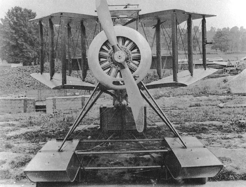
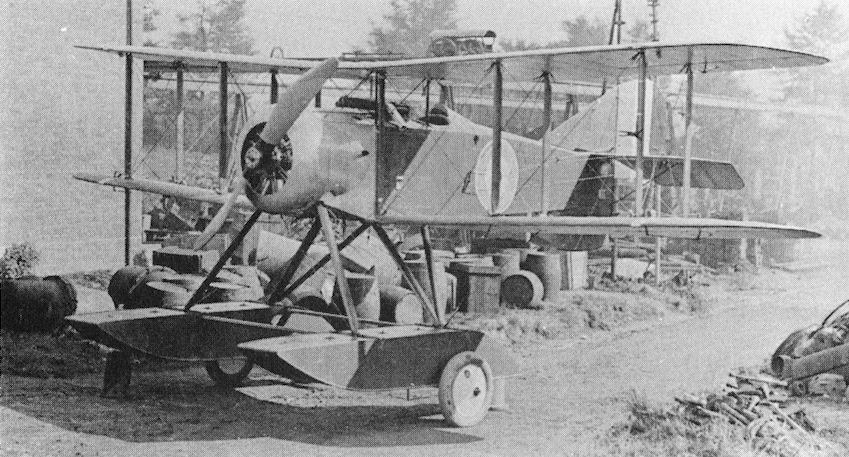
Two N.1Bs were built by Westland with some minor differences between them. The first, 16, was fitted with 11 ft long Sopwith main floats and a 5 ft long tail float carrying a water rudder which was moved by a vertical shaft extending down from the aircraft's rudder. In N17, the second aircraft, these were replaced by Westland-designed floats 17 ft 6 in in length with swept-up aft ends which made the tail float unnecessary. Some reports indicate that these floats could be fitted with a through axle carrying two wheels to enable the N.1B to take-off and land on suitably equipped vessels at sea, but no evidence of this design feature can be traced. The wheels which are shown in photographs are almost certainly those of a ground-handling trolley.
Completed during the summer of 1917, in August the renowned Harry Hawker flew N16 on its first flight from Yeovil. In October at least one Westland N.1B, N16 - and possibly both aircraft - went to the Royal Naval Air Service Experimental Construction Depot at Port Victoria on the Isle of Grain for evaluation where it was flown by Sqn Cmdr J W Seddon who, in 1913, as a young Lieutenant RN flying instructor, had had as a pupil the fledgling aviator and the First Lord of the Admiralty, Mr Winston Churchill. The reports of its evaluation against the PV.2, built by the Royal Naval Air Service Depot at Port Victoria, showed that the Westland N.1B performed well and exhibited good handling characteristics; however, before the type could be developed, a change of policy ensued. Landplane single-seat fighters, such as the Sopwith Pup and Camel, had demonstrated their ability to take-off and land on vessels underway at sea, thus removing the need for the carriers to heave to and either drop or pick-up seaplanes. Because of this change of emphasis, further production and development of the Blackburn, Westland and Supermarine N.1Bs was abandoned after cancellation of the contracts in 1917.
Description: Single-seat floatplane fighter. All-wood construction with metal and fabric covering.
Accommodation: Pilot in open cockpit.
Powerplant: One 150 hp Bentley AR.1 nine-cylinder air-cooled normally-aspirated rotary engine driving a 9 ft diameter wooden propeller.
Armament: One Vickers .303 in machine-gun firing forward and one Lewis .303 in machine-gun on a swivel mounting on the upper centre-section. Two 65 lb bombs carried in tandem under the fuselage.
Dimensions: Span 31 ft 31/2 in; length 26 ft 5 1/2 in; height 11 ft 2 in; wing area 278 sq ft.
Weights: Empty (N16) 1,504 lb, (N17) 1,513 lb. Loaded (N16) 1,978 lb, (N17) 1,987 lb.
Performance: Maximum speed (N16) 108.5 mph, (N17) 107 mph at sea level; alighting speed 50 mph; climb to 5,000 ft in 10 min.
Production: Two prototypes built by Westland Aircraft Works, Yeovil, Somerset, during 1916-17.
In 1916, with a growing number of Royal Navy ships capable of carrying and launching aircraft with wheeled undercarriages or floats, the Air Department of the Admiralty was examining the potentialities of single-seat fighters. It was also considering the means whereby such an aircraft could be designed and produced to meet naval requirements. Thus the Air Department N.1B requirement was for a single-seat shipboard float plane or flying-boat fighter having a speed of 95 knots (110 mph) at 10,000 ft and a ceiling of at least 20,000 ft. This latter requirement was particularly exacting, bearing in mind the comparatively low power/weight ratios and levels of reliability of the engine available at that time.
Three aircraft manufacturers prepared designs to meet this requirement; they were the Blackburn Aeroplane and Motor Co, the Supermarine Aviation Works and Westland Aircraft Works. Both the Supermarine and Blackburn designs were pusher biplane flying-boats but the other design, the first to emanate from the Westland Aircraft Works, was a more conventional tractor biplane floatplane. Contracts for the construction of a total of eight prototypes, all designated N.1B, were placed with the three companies; three each by Blackburn and Supermarine and two by Westland.
The design of the two Westland N.1B was the work of Robert Bruce and Arthur Davenport, the company's manager and chief draughtsman respectively. The construction, understandably, followed the standard pattern of that era. The fuselage was a conventional rectangular-section structure with four longerons and internal wire-braced frames of spruce with steel end fittings, the front ends of the longerons carrying the mounting for the 150 hp Bentley AR.1 (for Admiralty Rotary) rotary engine. Wooden formers on the upper longerons provided a rounded top surface to the fuselage. The cockpit surround was of leather-edged ply and had a small head fairing. The entire tail unit was an externally wire-braced wooden structure. The constant chord two-bay biplane wings were built up around two ash main spars with wire-braced spruce struts and ribs, and spruce interplane struts. Ailerons and trailing-edge flaps, described as a 'wing camber-changing device patented by Robert Bruce', were fitted on all four wings. The wings were designed to fold back against the fuselage sides for shipboard stowage without requiring a jury strut to be fitted at the front spar root-end fittings. Wire-braced spruce alighting gear struts carried two rectangular-section floats, each with a number of watertight compartments. Control wires to the elevators and rudder were run externally from the cockpit but those to the ailerons and flaps were routed inside the wings. The airframe was fabric-covered with a metal engine cowling and top and side panels at the forward end of the fuselage. Armament was a fixed forward-firing Vickers .303 in machine-gun, synchronised to fire through the propeller disc and mounted in a metal 'hump' fairing on top of the fuselage in front of the cockpit, plus a Lewis .303 in gun on a swivel mounting on the upper centre-section above the cockpit. A cross-bar on the centre-section leading-edge appeared to serve the dual purpose of preventing the gun from being fired through the propeller arc and serving as a front mounting for the gun fixed to fire either slightly to port or starboard. In addition two 65 lb bombs could be carried in tandem on tubular carriers attached on the aircraft's centre-line under the fuselage.
Two N.1Bs were built by Westland with some minor differences between them. The first, 16, was fitted with 11 ft long Sopwith main floats and a 5 ft long tail float carrying a water rudder which was moved by a vertical shaft extending down from the aircraft's rudder. In N17, the second aircraft, these were replaced by Westland-designed floats 17 ft 6 in in length with swept-up aft ends which made the tail float unnecessary. Some reports indicate that these floats could be fitted with a through axle carrying two wheels to enable the N.1B to take-off and land on suitably equipped vessels at sea, but no evidence of this design feature can be traced. The wheels which are shown in photographs are almost certainly those of a ground-handling trolley.
Completed during the summer of 1917, in August the renowned Harry Hawker flew N16 on its first flight from Yeovil. In October at least one Westland N.1B, N16 - and possibly both aircraft - went to the Royal Naval Air Service Experimental Construction Depot at Port Victoria on the Isle of Grain for evaluation where it was flown by Sqn Cmdr J W Seddon who, in 1913, as a young Lieutenant RN flying instructor, had had as a pupil the fledgling aviator and the First Lord of the Admiralty, Mr Winston Churchill. The reports of its evaluation against the PV.2, built by the Royal Naval Air Service Depot at Port Victoria, showed that the Westland N.1B performed well and exhibited good handling characteristics; however, before the type could be developed, a change of policy ensued. Landplane single-seat fighters, such as the Sopwith Pup and Camel, had demonstrated their ability to take-off and land on vessels underway at sea, thus removing the need for the carriers to heave to and either drop or pick-up seaplanes. Because of this change of emphasis, further production and development of the Blackburn, Westland and Supermarine N.1Bs was abandoned after cancellation of the contracts in 1917.
Description: Single-seat floatplane fighter. All-wood construction with metal and fabric covering.
Accommodation: Pilot in open cockpit.
Powerplant: One 150 hp Bentley AR.1 nine-cylinder air-cooled normally-aspirated rotary engine driving a 9 ft diameter wooden propeller.
Armament: One Vickers .303 in machine-gun firing forward and one Lewis .303 in machine-gun on a swivel mounting on the upper centre-section. Two 65 lb bombs carried in tandem under the fuselage.
Dimensions: Span 31 ft 31/2 in; length 26 ft 5 1/2 in; height 11 ft 2 in; wing area 278 sq ft.
Weights: Empty (N16) 1,504 lb, (N17) 1,513 lb. Loaded (N16) 1,978 lb, (N17) 1,987 lb.
Performance: Maximum speed (N16) 108.5 mph, (N17) 107 mph at sea level; alighting speed 50 mph; climb to 5,000 ft in 10 min.
Production: Two prototypes built by Westland Aircraft Works, Yeovil, Somerset, during 1916-17.
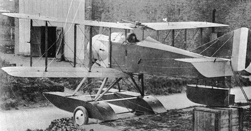
N16, the first N.1B, with a tail float and a humped cowl over the Vickers machine-gun.
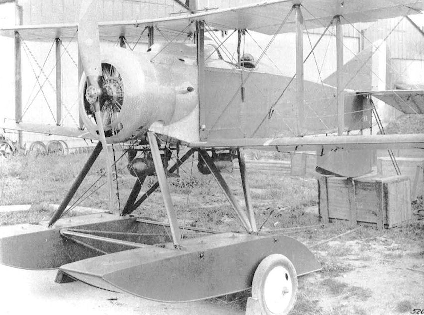
This close up of Westland N16 shows the engine cowling's fine finish, 'hump' for Vickers gun, the gun port in its cowl, two 65 Ib bombs under the fuselage and Lewis gun over centre-section. The pistol grip and spade grip of the Lewis gun are seen above the cockpit.
N16 with wings folded and carrying a 65 Ib bomb under the fuselage. Note the slotted engine cowling and absense of jury struts.
Longer float on N17 allowed the tail float to be removed.
N17, the second N.1B, had a modified engine cowling and an uncowled Vickers gun.
N.1B
Wagtail
Although the Royal Air Force had not been founded until 1 April, 1918, during the last few months of the 1914-18 War a number of new single-seat fighters designed to meet the RAF Type I Specification were nearing completion. Among those companies producing prototypes was Westland whose small design team, led by Robert Bruce and Arthur Davenport, had been considering the design of a small fighter during the latter half of 1917. One of the requirements of the outline Type I Specification for a light fighter was that it should have an engine delivering 50 hp more than the 130 hp Clerget rotary engine in the Sopwith Camel. This increase in power, plus the smaller size implicit in the 'light fighter' description, was aimed at producing a performance which would exceed that of the Camel, both in terms of maximum speed and rate of climb, with improved handling characteristics.
At about the time when this specification was issued the Air Board was examining a recently-introduced experimental seven-cylinder air-cooled radial engine. Designed by Granville Bradshaw who had founded ABC Motors, the successor to ABEC (All British Engine Company), it weighed 290 lb, was of 657 cu in capacity and produced 170 hp. Named Wasp, it was engineered throughout for easy production; however, one of its design features, which was the use of copper-plated steel cooling fins on the cylinders, was to contribute to its future unreliability. It was this engine which the Westland design team had in mind for possible use in its private venture light fighter, provisionally known as the Hornet, and which was to power it when built as the Wagtail.
Of conventional external appearance and construction, the Wagtail had a wooden girder type fuselage. rectangular in section for most of its length, with light wood fairings to provide shape. Spruce longerons of square-section were employed with staggered vertical and horizontal spacer struts tapering to fit into square cups in light steel fittings bolted to the longerons. These fittings also carried attachment lugs for the swaged rods which braced each bay of the fuselage structure. The braced tailplane and fin were of similar wooden construction while the elevators and rudder were of metal. The rear fuselage aft of the cockpit, which was located under the upper wing trailing-edge, was fabric covered and removable fabric covered panels enclosed the cockpit and the forward fuselage, wire-braced engine mounting ring with four attachment plates was carried on inwardly curved extensions of the longerons with the entire nose and engine having removable metal top and side panel and a metal cowling through which the Wasp's seven cylinders protruded. Inverted-V main undercarriage legs of spruce carried a cross-axle with bungee rubber shock absorbers and a curved tailskid was mounted below the tailplane leading-edge. The main spars of the constant-chord single-bay wings were of ash with cross-braced drag struts and the spruce ribs of RAF 15 aerofoil section were built up from three-ply webs with spruce capping strips.
The Type I Specification stressed the need for a good all-round view for the pilot; thus the flat wide-span upper centre-section - a feature to minimise the spar bending moment - had a large trailing-edge semi-circular cut-out above the cockpit, and was supported on two pairs of outwardly-canted struts. Constant-chord wide-span ailerons were carried on both the upper and lower wings which, in the prototype Wagtail, C4291 , had the same 2 1/2 deg dihedral and were wire-braced. The wings and tail unit were fabric-covered. In this aircraft too the fin had a long dorsal extension well in front of the tailplane leading-edge. Control wires to the ailerons and rudder ran inside the wings and fuselage but were carried externally to the elevator. Fuel was carried in a 26 gal fuselage-mounted tank in front of the cockpit, two synchronised Vickers .303 in guns were mounted on top of the fuselage and oxygen equipment was located in the cockpit.
Originally six Wagtails were ordered by the Air Board and allocated the serials C4290-96 but the contract was later reduced to three aircraft, C4291-93. Construction of the first Wagtail airframe was completed by the end of February 1918 with production of two more, C4292 and 4293, well in hand; however C4291's Wasp engine was still awaited from the manufacturer. During this period Capt F Alexander, Royal Flying Corps, was attached to Westland Aircraft Works to fly the Wagtail. With operational experience he believed that the cut-out in the prototype's centre-section should be larger. Because a modification at that stage would have delayed the first flight, a re-designed centre-section was first fitted, as a trial installation, to the incompleted third aircraft. The three central rib aft of the front spar and the centre-section trailing-edge were removed leaving a wide aperture spanned only by the nosing and the rear spar. This new centre-section was mounted six inches lower than on the prototype and in order to use the same length faired tubular steel interplane struts and bracing wire, the lower wings were re-rigged flat and the upper wings given 5 deg dihedral. While the modified centre-section improved the pilot's view, what was not quantifiable or immediately recognisable was the effect the loss of wing area had upon wing lift and air flow disturbance.
The first flight date of 4291 has not been established; however, it is known that it took place early one morning in April 1918, and that the Wagtail's handling characteristics were such that they inspired apt Alexander to execute a loop. This test flight also suggested that there was insufficient rudder area to counteract the nose-down effect of the fin in a side-slip; in order to minimise the time and cost involved in building a larger rudder, it was decided to cut back the fin to about half of its length. Meanwhile, work on fitting the modified centre-section and fin to the second and third aircraft was in progress.
Within a week or so the first of many engine snags, which were to plague the Wasp, were encountered and it was removed from C4291 for return to the manufacturer. Much of the trouble stemmed from valve and cylinder design and cooling. When C4291 's engine was returned to Yeovil it was fitted to the second Wagtail, C4292, which had the modified centre-section and wings and was nearer completion than the third airframe. With this engine test flying was resumed on 29 April; but soon afterwards this Wagtail was badly damaged while in a canvas Bessoneaux hangar at Yeovil which had caught fire when an employee had been endeavouring to prove that he could extinguish a lighted cigarette in a can of petrol!
With the arrival of two more Wasp engines the third Wagtail was quickly completed, enabling it to fly early in March, and work on modifying the prototype's centre-section and fin was pressed forward. On 8 May C4293 was flown to the Aircraft Experimental Establishment at Martlesham Heath for 'fighter trials' with a number of different propellers. Unfortunately, after a badly executed landing on 18 May, the Wagtail nosed over on rough ground damaging the engine and undercarriage. After repairs this aircraft was transferred to the Royal Aircraft Factory at Farnborough on 27 May, only a few days before it was renamed Royal Aircraft Establishment, a name it was to retain for the ensuing 70 years. There it was used by the RAE and ABC to investigate the source of the Wasp's problems; but the programme was short-lived for two weeks later all trials of Wasp-powered aircraft - which included the Sopwith Snail and the BAT Bantam - were halted. However, it is recorded that, in July 1918, C4293 was at Martlesham Heath for 'motor trials' but for how long is not known.
The prototype Wagtail, meanwhile, had been re-engined and the airframe modifications had been embodied. It flew again at about the same time that Wasp investigations ceased; nevertheless it went to the RAE thereafter and is recorded as having been at Martlesham Heath during August for evaluation against other fighters, presumably the Camel, Snail and Bantam. Then, on 6 November it went to the Aircraft Armament and Gunnery Experimental Establishment at Orfordness for gun firing trials. By this time not only was the War finished but all flying trials with Wasp-powered light fighters had been terminated and production of this engine been cancelled. Nevertheless, like Charles II, the Wagtail/Wasp combination was 'an unconscionable time dying' and on 29 January, 1919, the rebuilt airframe of the second aircraft, C4292, arrived by road at Martlesham Heath where it was to remain at least until 1920.
In spite of numerous problems with the Wasp, ABC continued to develop this engine and one of the Wagtails is reported to have flown with a 200 hp Wasp II. But this was not the end of Wagtail production for in 1920 two more Wagtails were ordered, powered by the new 150 hp Armstrong Siddeley Lynx seven-cylinder air-cooled radial engine. Serialled J6581 and J6582, airframe modifications included shortening the fuselage by removing the metal-panelled bay aft of the engine to maintain the centre of gravity with the heavier Lynx, changing the shape of fin and rudder to a 'comma' shape and fitting a stronger main undercarriage to suit the increased all-up weight. These two aircraft were flown at the RAE and at Martlesham Heath until about 1922, some record indicating that at least one, J6582, having also been powered by a Wasp II.
Description: Single-seat light biplane fighter. Wood/metal construction with fabric and metal covering.
Accommodation: Pilot in open cockpit.
Powerplant: One 170 hp ABC Wasp seven-cylinder air-cooled normally-aspirated radial engine driving a two-blade 7 ft 4 in diameter wooden propeller.
Armament: Two fixed synchronised Vickers .303 in machine-guns mounted on top of the fuselage, with 1,000 rounds of ammunition.
Dimensions: Span 23 ft 2 in: length 18 ft 11 in; height 8 ft 0 in; wing area 190 sq ft.
Weights: Empty 746 lb; loaded 1,330 lb.
Performance: Maximum speed at 10,000 ft 125 mph; landing speed 50 mph; climb to 5,000 ft in 3.5 min, to 17,000 ft in 17 min; service ceiling 20,000 ft.
Production: Five Wagtail built by Westland Aircraft Work, Yeovil, Somerset, during 1917-20.
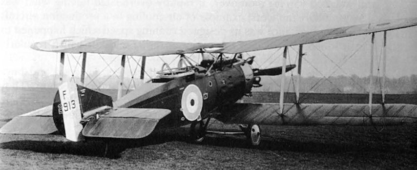
The third Wagtail, C4293, with the flat lower wing and increased dihedral on the upper wing. Retouching has removed the tailskid.
Developed to meet the RAF's Type I Specification for a 180hp engined, single seat fighter replacement for the Sopwith Camel, the attractively proportioned Westland Wagtail appears to have been a sound enough airframe design, let down by a totally undeveloped engine in the shape of the 170hp ABC Wasp. First flown during April 1918, the twin Vickers gunned Wagtail, like its its rivals, the BAT FK 23 Bantam and Sopwith Snail, was quietly left to wither away, following the official abandonment of the Wasp towards the close of 1918. Top level speed of the Wagtail was a useful 125mph at 10.000 feet, while it took a mere 3 minutes 30 seconds to reach an altitude of 5.000 feet. Interestingly, both of these performance figures are superior to those of the Sopwith Snipe with its far more powerful 230hp rotary. Only three Wagtails were to be completed, the last, serial no C 4293 being seen here.
Developed to meet the RAF's Type I Specification for a 180hp engined, single seat fighter replacement for the Sopwith Camel, the attractively proportioned Westland Wagtail appears to have been a sound enough airframe design, let down by a totally undeveloped engine in the shape of the 170hp ABC Wasp. First flown during April 1918, the twin Vickers gunned Wagtail, like its its rivals, the BAT FK 23 Bantam and Sopwith Snail, was quietly left to wither away, following the official abandonment of the Wasp towards the close of 1918. Top level speed of the Wagtail was a useful 125mph at 10.000 feet, while it took a mere 3 minutes 30 seconds to reach an altitude of 5.000 feet. Interestingly, both of these performance figures are superior to those of the Sopwith Snipe with its far more powerful 230hp rotary. Only three Wagtails were to be completed, the last, serial no C 4293 being seen here.
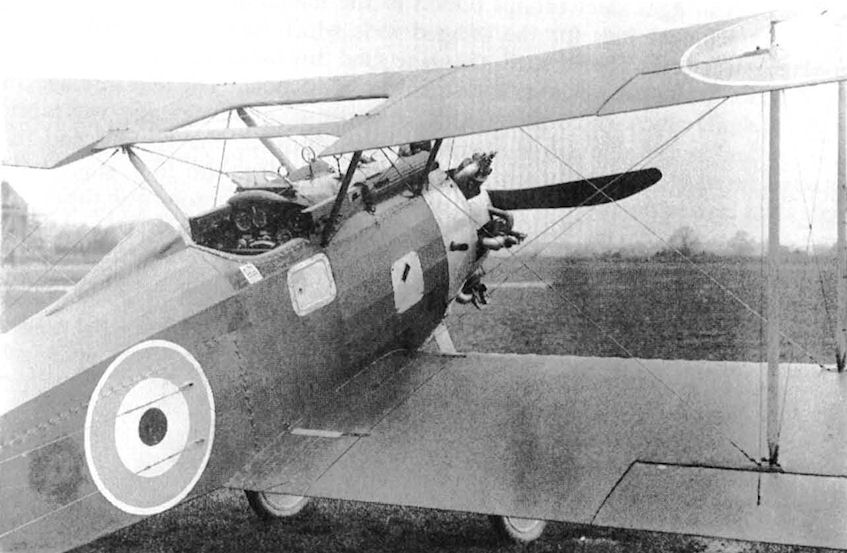
Wagtail showing the twin Vickers guns, ring-and-bead sight, brackets and perforated windscreen for Aldis sight, centre-section configuration and case chute in side panel.
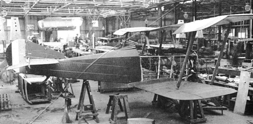
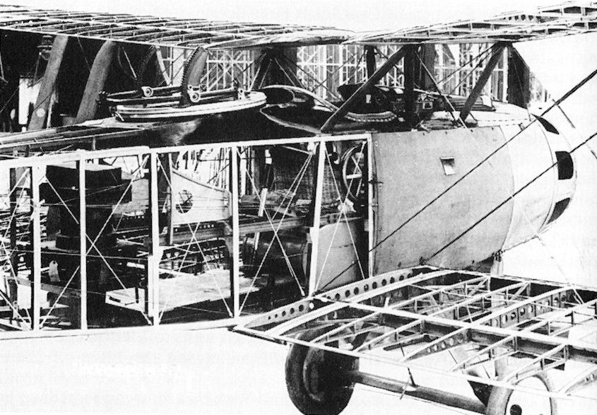
Wagtail C4291 under construction, with broad-chord fin extending forward of the tailplane, equal dihedral wings and reverse taper on inboard sections of the upper wings.
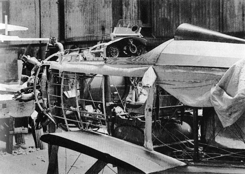
A Wagtail under construction. The elevator control system, wing aerofoil section and fuel tank locations are notable features.
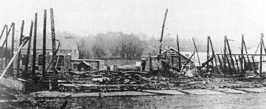
A burnt out Bessoneaux hangar and a badly damaged Wagtail was the result of an employee's experiment with a cigarette and a tin of petrol.
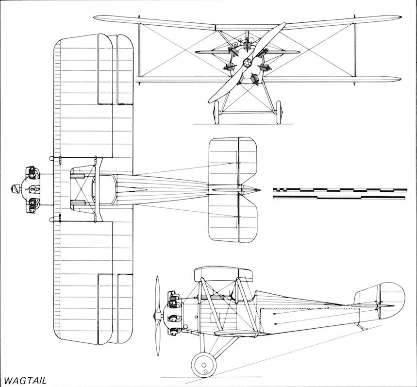
Wagtail
Weasel
During the final months of the 1914-18 War the Air Ministry was already giving thought to its postwar aircraft requirements and preparing some detailed specifications. Among these was RAF Type IIIA for a two-seat fighter-reconnaissance aircraft. It was intended as a replacement for the highly effective Bristol F.2B Fighter - the 'Brisfit' - which was still a comparatively new design having entered service with the Royal Flying Corps in April 1917. The Type IIIA specification called for a much improved performance, particularly in the time-to-height and service ceiling; however, the armament remained the same as the F.2B, being two fixed forward-firing guns and one gun on a Scarff ring mounting in the rear cockpit. The most unfortunate aspect was the preferred use of the ABC Dragonfly engine, a nine-cylinder radial engine designed, like the earlier Wasp which powered the Wagtail, by Granville Bradshaw. The Dragonfly proved to be a disaster in almost every way. It was claimed to produce 340 hp and weigh 600 lb but never, at any stage, delivered more than 295 hp and weighed 656 lb; moreover, it rapidly overheated having what was described as 'probably the worst example of air cooling in a production aircraft engine’. Of most importance was its designed running speed which happened to be the critical torsional vibration frequency of the crankshaft which regularly broke after a few hours running.
It was around the Dragonfly that three manufacturers designed and built prototypes, in various quantities, to meet the Type IIIA requirement. They were the Austin Motor Co which produced the Greyhound, Bristol Aeroplane Co with the Badger and Westland which scaled up its earlier single-seat Wagtail to create the two-seat Weasel.
Designed by Robert Bruce and Arthur Davenport, the Weasel was of similar construction to the Wagtail having a wooden girder type fuselage of rectangular cross-section with spruce longerons and spacer struts, the latter being tapered to fit into square steel cups bolted to the longerons. This structure was internally wire braced. Forward of the front cockpit the fuselage was plywood covered with fabric covering on the remainder; however, a small rectangular area on each side of the observer' cockpit was left uncovered to provide a 'window'. The strut-braced tail unit, which had the Westland-patented variable-incidence tailplane gear, was of similar wire-braced wooden construction and also was fabric covered. The engine mounting ring was carried on an extension of the longerons which was internally wire braced, while the complete nose section of the fuselage had removable metal panels to provide access to the engine and to the fuel and oil tanks. The engine's cylinder heads protruded through holes in the nose cowl and the Dragonfly turned a 9 ft 9 in diameter two-blade fixed-pitch wooden propeller. The fabric-covered two-bay biplane wings were built up around two ash spars with cross-braced drag struts and three-ply cut-out ribs with spruce flanges. The eight interplane struts were of streamline section spruce and, like the four centre-section support struts, were all wire cross-braced. Constant-chord ailerons were fitted to each of the four wings. As in the Wagtail, although the centre-section was smaller in span, there was an angular cut-out in its trailing edge and in that of the lower wings' trailing edge; in addition five ribs were omitted in the centre-section aft of the main spar leaving an uncovered opening above the pilot's cockpit. The two fixed forward-firing synchronised Vickers .303 in machine-guns were carried in troughs in the top of the front fuselage, with provision for one, or two, Lewis guns of similar caliber to be carried on a Scarff ring mounting in the observer's cockpit. Spruce V main undercarriage legs with a cross-axle having enclosed bungee rubber shock absorbers were used with a tailskid. A wind-driven generator was mounted on the port rear main leg. An unusual visual feature of the Weasel was the manner in which the upper and lower wings appeared to be splayed away from each other; in fact, the upper wing had 5 deg dihedral from the flat centre-section while the lower wing had no dihedral. Oxygen bottles with some 3 hours supply for the two crew and electrical heating equipment were carried in the fuselage.
An order for three Weasel prototypes was placed in April 1918 with construction starting almost immediately, but forthcoming events cast their shadows over the work with the first of a number of delays in delivery of the engine. In 'the event the war was ended when the first Weasel, serialled F2912, was flown for the first time by Capt Stuart Keep during late November 1918.
Preliminary flight trials were punctuated by continuous problems with the engine, both on the ground and in the air. One incident, which could have had serious results for Westland, occurred when Stuart Keep was flying the Weasel with Robert Bruce in the observer's cockpit and the engine failed a long way from the aerodrome. Bruce immediately leaned out of the cockpit and cranked the starter magneto which was fitted on the starboard side of the fuselage, but the Dragonfly refused to start. Fortunately, the Weasel had sufficient altitude to glide back to the aerodrome, brushing through the top of the boundary hedge en route to a dead-stick landing. While company trial with this first prototype continued into the early months of 1919, construction of the second and third aircraft proceeded at a steady pace. During May F2912 went to the AEE at Martlesham Heath for 'airframe and Dragonfly motor' tests. These included some handling checks during which the lateral control was criticised. Meanwhile, as a result of the failures of the Dragonfly, it was decided to replace it with a 350 hp Armstrong Siddeley Jaguar II engine, the first airframe to be modified being the third prototype F2914 which went to Martlesham Heath during June 1922. Among airframe modifications was the fitting of horn-balanced ailerons and rudder.
While construction of the second and third Weasels had been proceeding, in August 1919, Westland received an order for a fourth aircraft to be powered by a Jaguar II. By this time all development testing of the disastrous Dragonfly had been abandoned and the production of military aircraft cut to a trickle; thus, Westland was aware that a production order for Weasel was unlikely to be placed. Nevertheless, flying with the four prototypes continued at Yeovil and at Martlesham Heath, at which latter location the Weasels made appearances until November 1924, when F2914, the third prototype was there. During November 1919 F2912, the first prototype, caught fire in the air while allegedly powered by an Armstrong Siddeley Lynx; however, it pilot, Flt Lt A H Orlebar, managed to sideslip to the ground and crash land where the fire was extinguished, the aircraft being written off charge in the following March.
By mid-summer of that year, all the Weasels had been handed over to the Royal Aircraft Establishment at Farnborough where they were being used for flight testing engine and various equipment. Although this work may have appeared mundane compared with operational flying, there was the interest of fitting and flying, in J6577, the exciting new Bristol Jupiter II radial engine which, in September 1921 was the first engine to pass the Air Ministry's type-test by delivering 400 hp at 1,625 rpm. However, there were installation problems, particularly with the Jupiter' valve gear which not only had some teething problems with its push rod which had automatic compensation for cylinder expansion, but also proved vulnerable to icing which topped the engine when tested in climbs to altitude during the winter month. To overcome this latter snag the RAE made some wind-tunnel investigations with a number of different shaped 'helmets' to fit over the Jupiter's exposed cylinder heads, and later test flew the Weasel with this modified cowling. There were moment of glory too, the first on 24 June, 1922, when the Jupiter-powered Weasel appeared in the New Types Park at the third Royal Air Force Pageant at Hendon. However, on 11 July J6577 caught fire in the air while at AEE, crashed and burnt out. F2914 was a 'New Type' at Hendon on 30 June, 1923, but, with F2913, flew at the RAE until written off charge in 1925 and 1924 respectively.
Description: Two-seat biplane fighter. Wood/metal construction with fabric, wood and metal covering.
Accommodation: Pilot and observer/gunner in open cockpits.
Powerplant: One 340 hp ABC Dragonfly nine-cylinder air-cooled normally-aspirated radial engine driving a 9 ft 9 in diameter two-blade wooden propeller (F2912). One 350 hp Armstrong Siddeley Jaguar II fourteen-cylinder two-row normally-aspirated air-cooled radial engine (F2912 and F2914). One 400 hp Bristol Jupiter II nine-cylinder normally-aspirated air-cooled radial engine (F2913 and J6577).
Armament: Two fixed synchronised Vickers .303 in forward-firing machine-gun in troughs in the top of the front fuselage with Aldis and ring-and-bead sights, and one, or two, Lewis .303 in machine-gun on a Scarff mounting in the rear cockpit.
Dimensions: Span 35 ft 6 in; length 24 ft 10 in; height 10 ft 1 in; wing area 36 sq ft.
Weights: Empty 1,626 lb; loaded 3,046 lb.
Performance: Maximum speed 120 mph at sea level; landing speed 56 mph; service ceiling 22,100 ft.
Production: Four Weasel built by Westland Aircraft Work, Yeovil, Somerset, during 1918-19.

The second Weasel, F2913, shows off its neatly cowled Jupiter engine and wide-span wings, the apparent splaying of which is an optical illusion.
This view of F2913 shows the large aperture in the upper centre-section, the cut-away wing roots and the generous size of the rudder and elevators.
Thi retouched photograph of the Weasel's structure reveals a full-chord wing root without a cutout. The pilot's basket-work seat is noteworthy, as are the neat decking around the cockpit and the Scarff ring.
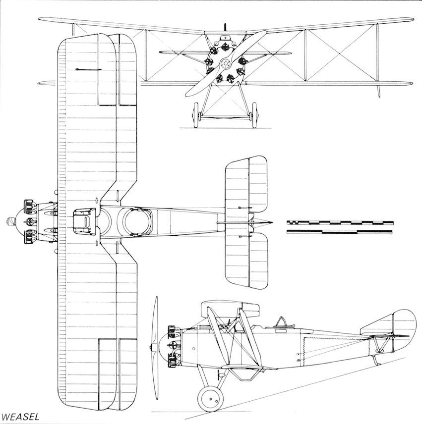
Weasel
Limousine
With the cessation of hostilities in November 1918, Arthur Davenport was already looking to the needs of postwar civil air services. Rather than attempt to produce Westland's first commercial aeroplane by modifying a proven military type, he struck out boldly with a completely new design with the declared intention of combining in a modern aeroplane all the best points of a high-class motor car with the principal advantage of an aeroplane: speed.
The outcome was the Limousine I, a single-engined two-bay biplane of wooden construction with fabric and wood covering. Although there were few, if any, new designs of engine available, Davenport chose the 275 hp Rolls-Royce Falcon III. This was a twelve-cylinder water-cooled vee engine - only the second of its configuration to be produced by Rolls-Royce - which had given high reliability service in several of the Bristol F.2B Fighter variants. Its installation in the Limousine I and II was reminiscent of that in the Fighter in that it also used the oval-fronted radiator employed in Bristol's renowned wartime two-seater.
The fuselage was built up in separate modules: a steel tube overhung-type engine mounting, the cabin section and the rear fuselage. The engine had metal cowling panels and was fitted with very long exhaust pipes which terminated more than half way along the fuselage to minimise exhaust noise in the cabin. The engine mounting structure was bolted directly to the cabin front bulkhead which had an asbestos layer between two multi-ply panels. This 'power egg' could be easily removed if an engine change was required or if an alternative type of engine was to be fitted.
To provide an unobstructed cabin the spruce and ash structure was covered with a three-ply skin which was reinforced around the door, the window and pilot's cockpit cut-out. In addition, the door, which was secured by an internal bar, had longitudinal reinforcing for additional rigidity. It was mounted on the starboard side, which had two windows, a single window being provided on the port side. A 50 gal fuel tank was carried immediately aft of the cabin front bulkhead. The rear fuselage was built up from a wood girder structure and was fabric-covered. It carried a fabric-covered tail unit, with small area vertical surfaces, of wood construction. To compensate for differing numbers and weights of passengers and their luggage, a tailplane trimming device was embodied in the design. The tailplane front spar was hinged to the top longerons and carried a hanging triangular frame inside the rear fuselage. The upper corners of the frame were attached to the two tailplane spars while the third lower corner was moved fore and aft in a rack and pinion type gear operated by a hand-wheel and Bowden cables from the pilot's position. The wings were of the traditional ash spars with spruce ribs and struts, the entire structure being internally wire-braced and fabric-covered. Ailerons of similar construction were carried on upper and lower wings and bumper bars were fitted below the two outboard pairs of interplane struts. A pair of spruce V undercarriage members carried a bungee-sprung through-axle and a tailskid was fitted.
The seating arrangement for the passengers and pilot certainly broke new ground. The pilot sat at the rear of cabin on the port side, his seat being raised 30 in above those of the passengers so that his head protruded through a hole in the cabin roof, a small windscreen being mounted in front of it. One wonders why Davenport placed the pilot behind the passengers. Was he influenced by a similar feature of the BAT FK.26, in which Fritz Koolhoven is reputed to have located the pilot as far aft in the fuselage as possible in order to give him the best chance of surviving a crash and thus being able to render an accurate and intelligent report on it? One passenger was seated on his lower right facing forward, a second immediately in front of him also facing forward, while the third passenger sat on the starboard side, facing aft, with a small folding table between him and the passenger behind. The reason for this seating configuration was that Davenport and Bruce saw the Limousine as an executive type aircraft in which meetings could take place and letters be dictated and typed ready for instant despatch when it landed. Thus, a secretary could fly, with her back to the engine, and a typewriter fixed to the table. It was later recorded that when the Limousine I prototype had become engaged in demonstration and sales flights, Westland's commercial manager. R J Norton, was 'ever ready to take up a secretary to demonstrate dictation in the air'.
The prototype, K-126 was completed and ready for its first flight by the end of July 1919, for which Stuart Keep was the pilot. During August, by which time the permanent civil registration G-EAFO had been allocated to this prototype, it went to the Aeroplane Experimental Establishment at Martlesham Heath for what were described as 'C of A performance trials' for the issue of its Certificate of Airworthiness on 21 August. Keep's initial reports indicated that there was some small amount of manageable longitudinal instability but that engine noise was low. This latter point was emphasised when passengers were carried, for a great deal of attention was paid to noise reduction in the cabin. The walls and roof were lined, the floor was carpeted and the luxurious grey, upholstered seats were thick and soft. All these and other measures helped to produce both a draught-free environment and noise level in flight no greater than that in a railway carriage. Flight reported Lady passengers may travel in this machine in the most delicate frocks without fear of getting them spoiled by oil'!
Production of a second airframe, the Limousine II, was completed in October 1919. Registered G-EAJL, it also had a 275 hp Falcon III but with a larger rectangular radiator and a redesigned fin and rudder of increased area. Demonstration and test flying continued during the ensuing six months and included a period at Martlesham Heath for evaluation of handling characteristics with the revised tail unit. Following a demonstration of the Limousine I at an air meeting organised by the Bournemouth Aviation Co at Winton racecourse on 1 May, 1920, this aircraft went to Croydon where G-EAJL was on loan to Air Post of Banks Ltd. From there both aircraft were used for experimental services to Paris, the fastest being recorded in September with a time of 1 hr 52 min. The chief pilot of this company was Frank T Courtney, a renowned freelance pilot but, like so many small aviation enterprises of its era. Air Post soon closed and both Limousines were returned to Westland.
Meanwhile a second Limousine II, G-EAMV, was built and was first flown in April 1920. It was intended as a test bed for the new 400 hp Cosmos Jupiter nine-cylinder radial engine designed by Roy Fedden and L F G Bunny' Butler. However, the Cosmos Engineering Co, based at Fishponds, Bristol, went into liquidation early in February 1920 and was not taken over by the Bristol Aeroplane Co until August. Thus it is surprising to find that the Limousine, rather than a Bristol aeroplane, was used for this work and, in the event, G-EAMV reverted to standard. A further three Limousine IIs were built, G-EARE, 'RF and 'RG, the first two, which had flown in October 1920, being leased to the new Instone Air Line, a company formed by the steamship-owning Einstein brothers, Samuel and Alfred, who had changed their name by deed poll. These two aircraft, fitted with 300 hp Hispano-Suiza 42 engines, flew regular Instone services on the routes to Brussels and Paris. In addition to a change of engine, the standard fuselage-mounted fuel tank, which was removed from its position aft of the engine where it was screened from the cabin by an asbestos-filled double-skinned wood bulkhead, was replaced by a streamlined external tank, under the port top wing, carrying 58 gal. The removal of the fuselage tank provided additional cabin volume making it even more spacious and luxurious. During 1922 Limousine IIs G-AEJL, 'MV and ‘RG were overhauled for their Certificate of Airworthiness renewal and were shipped to Newfoundland, the first two in July and the third in November, (see LimousineIII)
When the rules for the Commercial Aeroplane Competition, sponsored by the Air Ministry, were announced, they were such as to inspire Robert Bruce and Davenport to build a much larger six-passenger version, the Limousine III, powered by a 450 hp Napier Lion II engine. This was almost a new aircraft type having a 5 ft 6 in longer fuselage, three-bay wings increased in span by more than 16 ft, and a redesigned tail unit without a central fin, this being replaced by two small finlets on the tailplane. To meet the short-field landing reqirements of the Competition's rules, wheel brakes were fitted and twin nosewheels were mounted on struts attached to the bottom longerons and the undercarriage. These were to prevent the aircraft from going onto its nose if heavy braking was required during the short-landing trials. These involved landing over a 50 ft obstacle and coming to a stop within a circle marked on the ground. Sideslip landings were not permitted. As with the Hispano-Suiza-engined Limousine IIs, the fuel tanks were carried externally under the lower wings which reduced the fire-risk and permitted smoking in the cabin, where all seats faced forward.
The prototype Limousine III, G-EARV, construction of which was accelerated by using the rear fuselage of Limousine II G-EARH, work on which was abandoned, was first flown by Stuart Keep during June 1920 and made ready for the flight to Martlesham Heath for the Competition. Here, in August, with silver painted wings and an eau-de-Nile fuselage, the Limousine III won the ?7,500 first prize in the small commercial aircraft section, narrowly beating the Sopwith Antelope into second place on a technicality. When Harry Hawker, the Sopwith pilot, landed the Antelope in the trials, he did so with the brakes on, which burst both tyres of the main undercarriage, and one of the forward pair. The Antelope thus produced an unmatched short-distance landing, which was not officially recognised as the aircraft was not intact! However, it received second prize of ?3,000. Westland's victory in this section of the Competition, sadly, did not bring a rush of orders even though the Limousine III showed remarkable economy and stability - enabling Keep to leave his seat and join his passengers in flight - and was, undoubtedly, ahead of its time. Such was the state of the commercial aircraft market that only one more Limousine III was built, which was acquired by the Air Council in April 1921 having been allocated the serial J6851, but this was not taken up. Subsequently, it was loaned to Instone Air Line, registered G-EAWF, as part of a Government scheme for approved operators, where it became a reserve aircraft in company with the Limousine IIs G-EARE and ‘RF, until all three were withdrawn from service in 1923.
Having taken first place, G-EARV was used by Westland for some development flying until January 1921 when it was sold to FS Cotton's Aerial Survey Company and moved to Newfoundland in a pioneering role in fishery and seal spotting operations. Flown by T Ê Breakell it was fitted with both ski and wheel undercarriage and was later used in the Stag Bay gold rush. By the end of 1923 RV had logged a substantial number of flying hours carrying passengers, cargo and mail to remote communities. It was then acquired by Laurentide Air Service Ltd, with whom it was to have been registered G-CAET. However, upon arriving at Lac a la Tortue, Laurentide's maintainance base, for an overhaul and inspection, part of the Limousine's wooden structure was found to be rotted and it was scrapped in 1924.
Description: Three/five-seat commercial biplane. Wood construction with fabric and wood covering.
Accommodation: Pilot and three or five passengers.
Powerplant:
One 275 hp Rolls-Royce Falcon III twelve-cylinder water-cooled normally-aspirated vee engine driving a two-blade wooden propeller. (Limousine I and II).
One 300 hp Hispano-Suiza 42 eight-cylinder water-cooled normally-aspirated vee engine driving a two-blade wooden propeller (Limousine II).
One 410 hp Cosmos Jupiter III nine-cylinder air-cooled normally-aspirated radial engine driving a two-blade wooden propeller (Limousine II).
One 450 hp Napier Lion 1A twelve-cylinder water-cooled normally-aspirated geared broad-arrow engine driving a 7 ft 10 in four-blade wooden propeller (Limousine III).
Dimensions: Span 38 ft 2 in (Limousine I), 37 ft 9 in (Limousine II); length 27 ft 9 in; height 10 ft 9 in; wing area 440 sq ft (Limousine I and II). Span 54 ft 0 in; length 33 ft 6 in; height 12 ft 6 in; wing area 726 sq ft (Limousine III).
Weights: (Limousine I) (Limousine II) (Limousine III)
Empty 2,183 lb 2,010 lb 3,823 lb
Loaded 3,383 lb 3,800 lb 5,850 lb
Performance:
Maximum speed 100 mph 100 mph 118 mph
Cruising speed 85 mph 90 mph 90 mph
Sea level
climb 600 ft/min 650 ft/min 600 ft/min
Service ceiling 17,000 ft 17,000 ft 12,300 ft
Range 290 miles 400 miles 520 miles
Production: A total of eight Limousines was built by Westland Aircraft Works, Yeovil, Somerset, during 1919-21 as follows: One prototype Limousine I. Five Limousine II production aircraft. Two Limousine III production aircraft.
(The Limousine I's initial registration K-126 was carried in accordance with the provisions of the United Kingdom Air Navigation Regulations, which came into force on 20 April, 1919, requiring all British civil aircraft to carry registration markings. The International Air Navigation Convention did not come into force until 22 July, 1919, and, during the interim period, the Air Ministry introduced a system of temporary markings. It required all aircraft newly constructed or built from spares to be registered in a sequence beginning at K-100. A total of 175 such registrations were allocated during the system's short life, although K-169 was the highest K-number known to have been used. Thereafter British aircraft carried a four-letter registration group prefixed by the letter G).
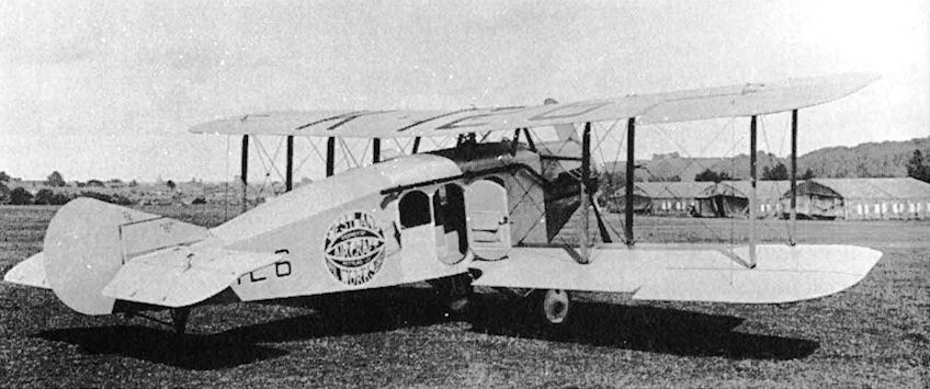
The Limousine I, K-126, seen at Yeovil in July 1919, has an oval nose radiator for its Falcon III engine. Visible are the windscreen of the offset cockpit, the very long exhaust pipe and the small fin and rudder.
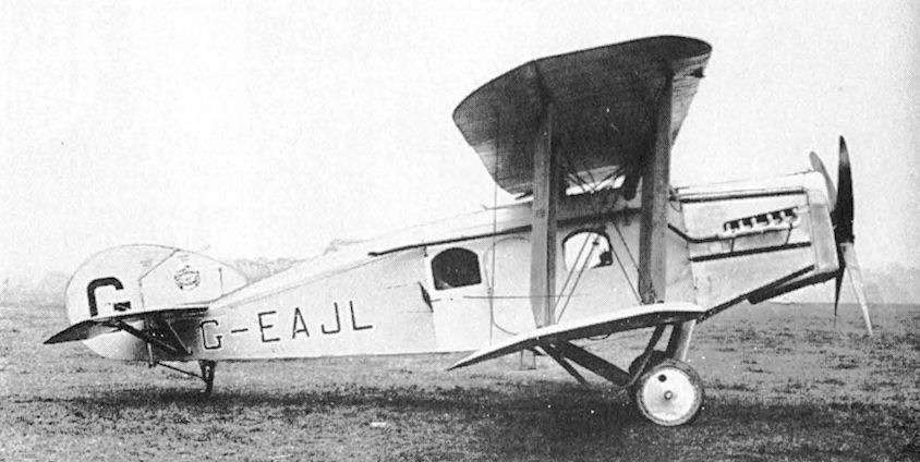
G-EAJL, the first Limousine II, appeared in October 1919 with an enlarged rectangular radiator and increased area fin and rudder.

G-EAJL, the Limousine II was exhibited at the 1921 Paris Aero Show in Ihe Grand Palais.
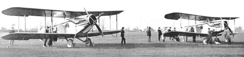
The Limousine I K-126 (left) and Limousine II G-EAJL being prepared for demonstration flights. Note the different radiators and four-blade propellers.

The prototype Limousine III at Yeovil in June 1920. The two small finlets on the tailplane, the large rudder and absence of a central fin were unusual features.
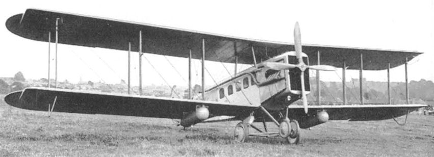
The Lion-powered Limousine III with underwing fuel tanks, twin-nosewheel undercarriage and three-bay wings.

G-EAWF was the second of two Limousine IIIs to be built. It flew with the Instone Air Line at Croydon as reserve aircraft.
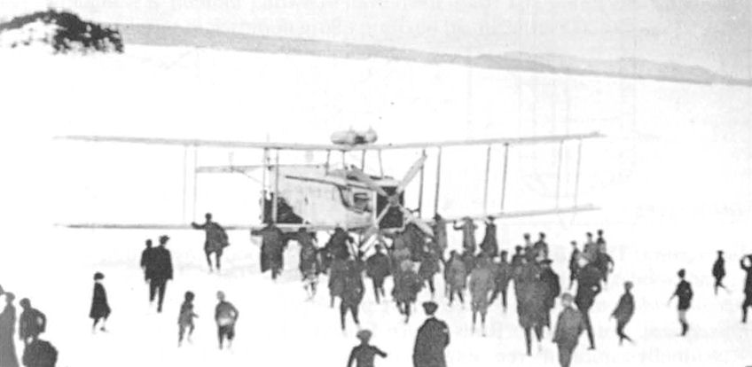
Sidney Cotton's Limousine III G-EARV being prepared for a seal-spotting flight at Botwood, Newfoundland, in 1921. It has overwing fuel tanks.
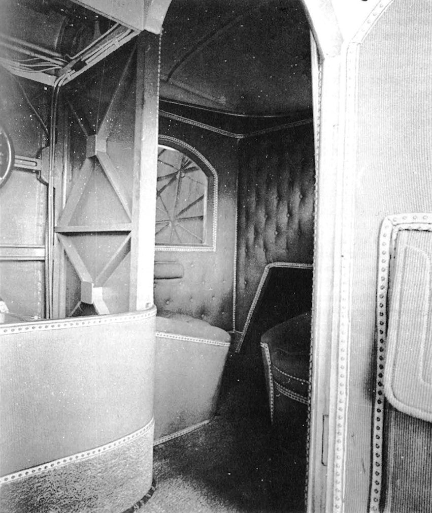
Luxury was the keynote of the passenger cabin, which was button-back lined, carpetted and fitted with thick upholstered seats. The more austere pilot's cockpit is on the left.