
Книги
Centennial Perspective
J.Herris
Zeppelin-Staaken Aircraft of WW1. Vol 1: VGO.1 - R.IV R.29/16
317
J.Herris - Zeppelin-Staaken Aircraft of WW1. Vol 1: VGO.1 - R.IV R.29/16 /Centennial Perspective/ (47)
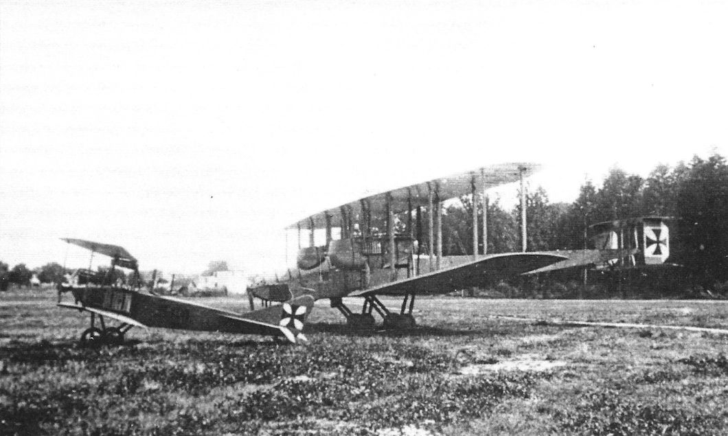
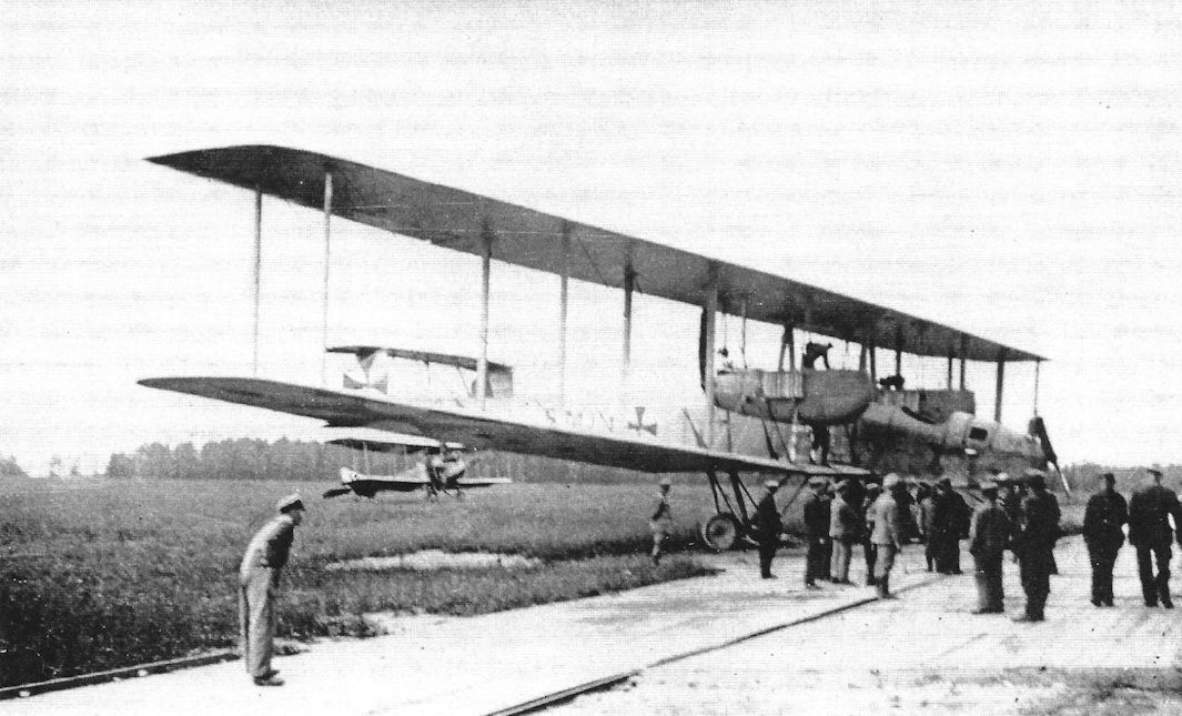
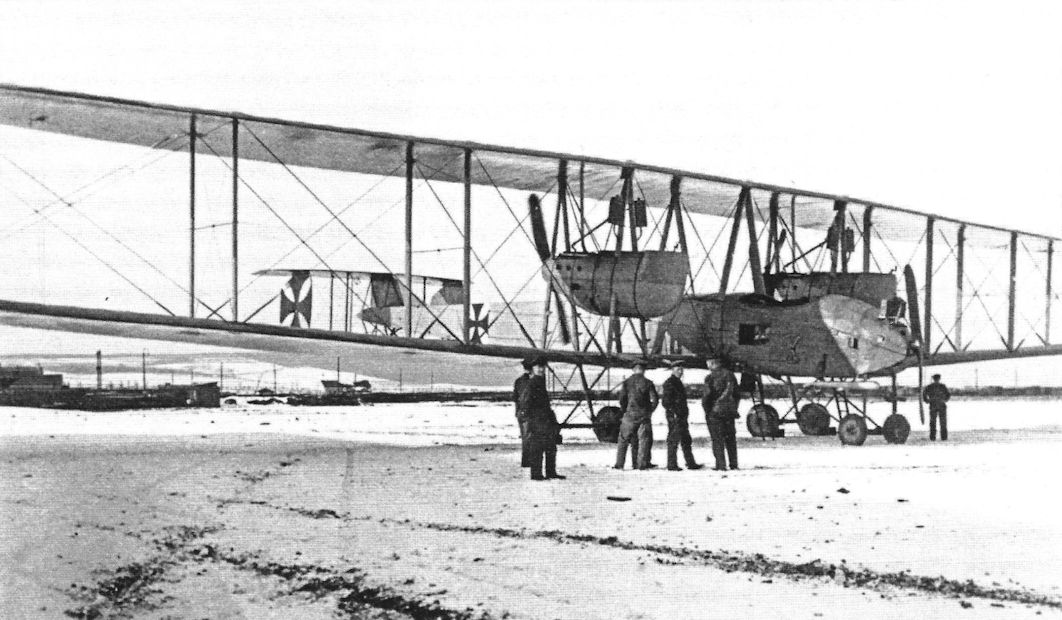
The V.G.O.I after modifications. There are now two tall fins and rudders. An Albatros B.II is in left foreground. (Peter M. Grosz collection/STDB)
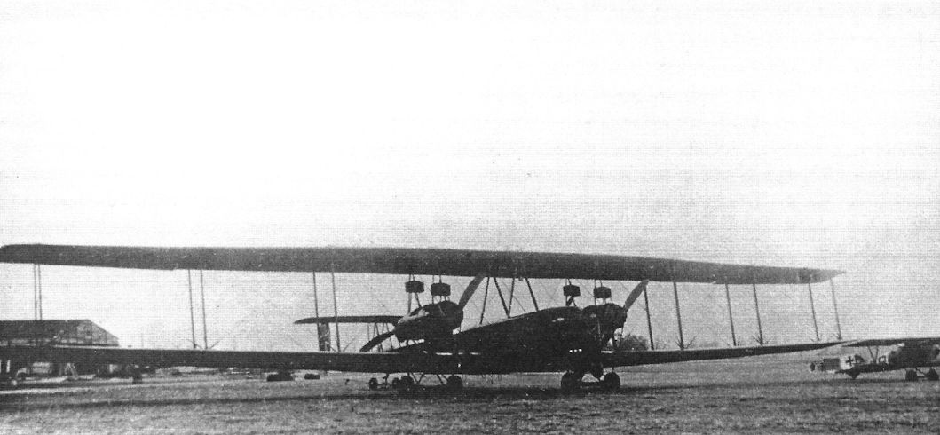
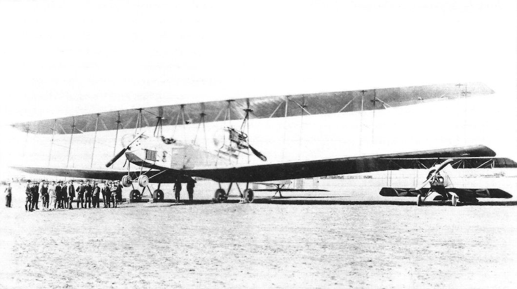
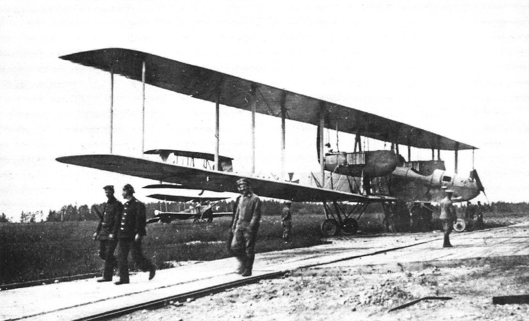
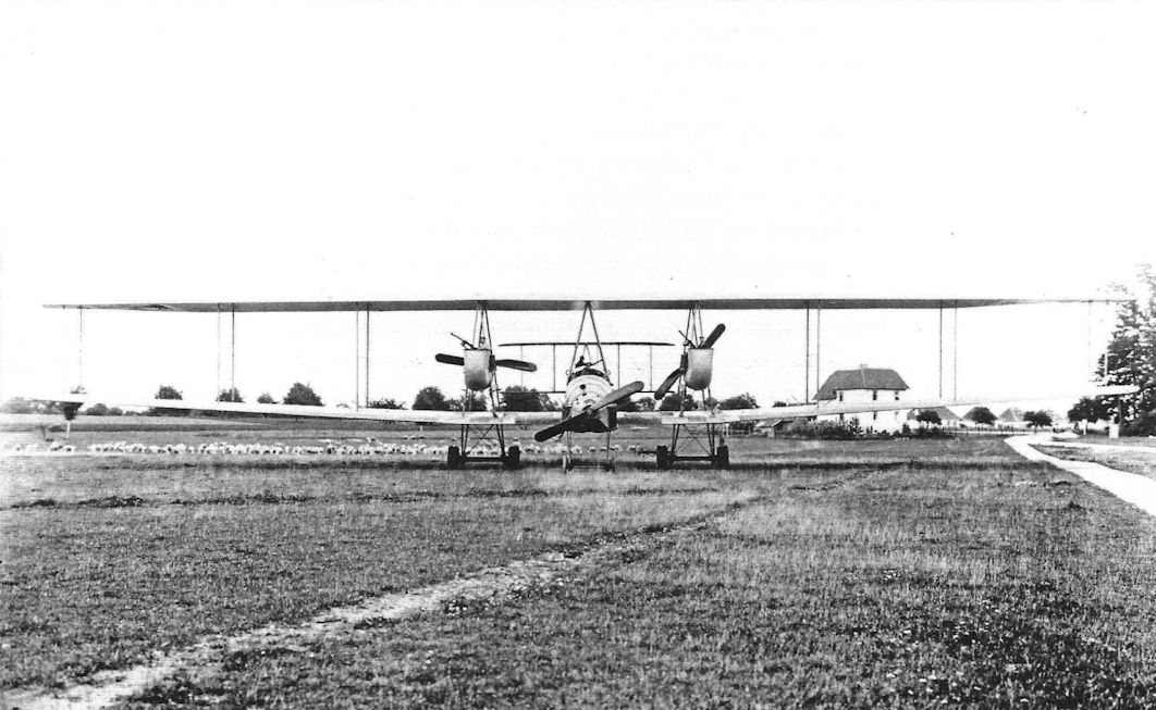
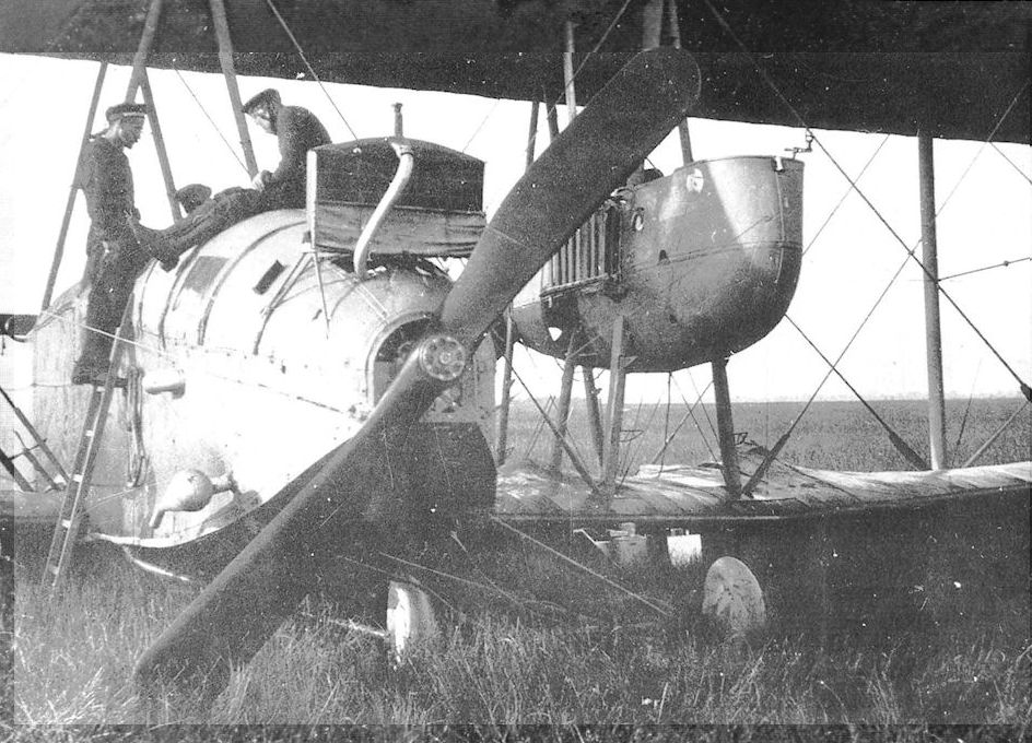
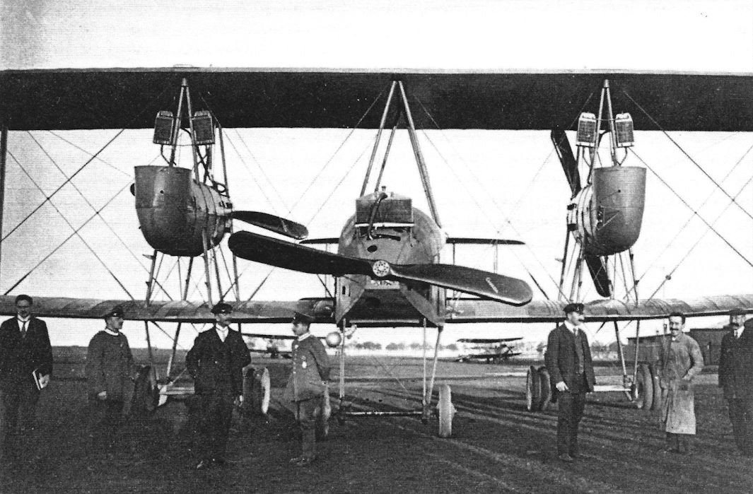
Front view of a Staaken R.VI on its field with Albatros D.V at right. (Peter M. Grosz collection/STDB)
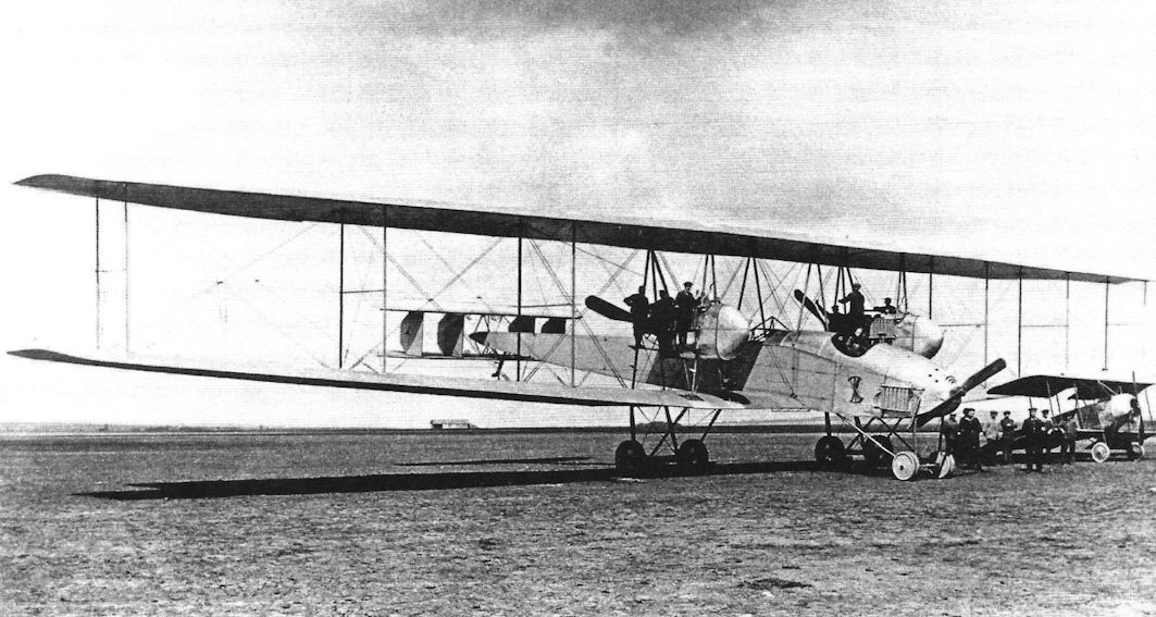
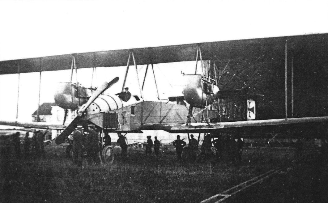
Staaken's first R-plane (R for Reisenflugzeug, or Giant airplane), the VGO.I in its original configuration; a Halberstadt B.I at right and the men give scale to the aircraft.The basic configuration, the wings, and the horizontal tail remained basically unchanged for Staaken bombers throughout the war. Note the four short fins and rudders. Amazingly, design of this aircraft began in December 1914, just 11 years after the first flight of the Wright brothers. Its wing span of 138.5' exceeded the 120' distance of the Wright's first flight. Each of its three propellers was powered by a 240 hp Maybach HS engine. Designed for airships, the HS engines were unreliable in airplanes due to the higher average power airplanes needed. (Peter M. Grosz collection/STDB)
VGO.I (R.M.L.I)
As war approached, Count Zeppelin turned his interest to heavy bombers as he realized the airship was a vulnerable and fragile weapon whose main use would be for reconnaissance. Two paths were chosen to move forward, wood construction and metal construction. Development of large metal bombers was entrusted to designer Claude Dornier and spun off to the Lindau facility.
To get a bomber in the air as fast as possible, conventional wood construction was pursued at another facility owned by Zeppelin. A new company called Versuchsbau G.m.b.H. Gotha-Ost (VGO - Experimental Works Gotha-East) was founded by Zeppelin and Bosch and buildings were rented on the Gotha airfield for space to assemble the wooden bomber. Remarkably, work on the new bomber was started in September 1914, less than eleven years after the Wright's first flight. The new giant bomber was a private venture and such was the urgency to complete it that its design had not been completed before construction began. In fact, construction had to be suspended in January 1915 pending arrival of the new 240 hp Maybach HS engines. Derived from airship engines, the new engines proved unsuccessful in the more demanding role as aircraft engines.
In addition to the design not being completed until December 1914, two months after the start of construction, there were other challenges. The Prussian War Office was not happy with the concept of a private venture and was not supportive of Zeppelin's effort. The start of the war in August caused serious shortages of skilled labor in all industries and raw materials were difficult to procure. Exacerbating all these issues was the bomber's unprecedented size. Despite these challenges, the VGO.I first flew on April 11, 1915.
Notwithstanding the aircraft's 1914 inception, the basic size, construction, and configuration of the VGO.I were successful enough that they were retained by Staaken designs throughout the war - and the Staaken designs were the most successful Giant bomber family designed in Germany.
Flight testing revealed an often under-appreciated challenge; the aircraft was so large and noisy, and the crew were so spread out, that crew coordination was a serious difficulty that impeded flight operations and sometimes compromised flight safety.
The VGO.I was an enormous biplane of conventional wood construction. It had three engines; one with tractor propeller in the nose and one in a nacelle between the wings on each side mounted in as a pusher. The VGO.I differed most noticeably from typical designs in its biplane tail surfaces, nose-wheel under-carriage, and huge size; smaller biplanes of the time almost invariably used a tail-skid instead of nose wheels and typically did not have biplane tails. However, a tail-skid was fitted in case of rough landings.
In accordance with its design role, the VGO.I had a bomb bay at its center of gravity large enough to carry a 1,000 kg bomb and provision was made for flexible defensive machine guns above and below the fuselage and in the front of the engine nacelles. The nacelle guns were to be fitted for the engine mechanics; to enable in-flight repairs thought to be necessary to sustain dependable high-endurance flight given the modest reliability of engines of the time. Provision for mechanics to move to the engine nacelles and spend time there was essential.
The VGO.I had good flying qualities. However, its new Maybach HS engines were a constant source of problems and slowed development of the R-plane programs using it, including that of the VGO.I. Until that engine, Maybach had focused on airship engines. These are not as highly stressed as airplane engines and in airships normally need to produce full power for relatively short periods on time. In contrast, aircraft engines need to provide maximum power for takeoff and the prolonged climb to cruise altitude, and in cruise flight have to produce a higher percentage of rated power than airship engines. Learning these lessons, then addressing the problems successfully, was a difficult, time-consuming process and Maybach was not able to fully achieve this with the HS engine.
As a result of the engine development problems, the VGO.I did not have HS engines that were reliable enough to attempt the Navy's reliability tests. On December 15, 1915, while returning to Gotha, two of the three oil lines to the engines failed during a snowstorm. With only one engine running, a forced landing was inevitable. With great skill the pilots were able to land the VGO.I in a forest clearing; the aircraft was badly damaged but were no injuries to the crew.
The VGO.I was rebuilt after this accident and a number of improvements were added during this process, including enlarging and balancing the rudders for more rudder control authority. The VGO. II, which had already been completed by this time, already embodied many of these improvements. Unfortunately, one item not changed was the unreliable engines. The Maybach HS was still the most powerful aircraft engine available at the time and apparently a desperate hope its problems could be solved was still alive. Unfortunately, this hope was unfounded.
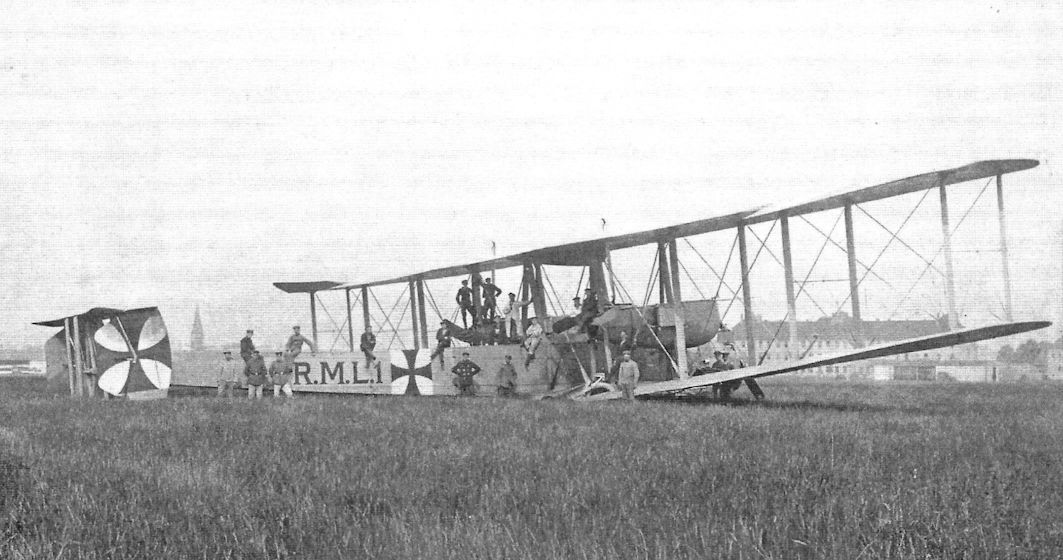
The re-built VGO.I was accepted by the Navy and given the designation RML.I for Reichs Marine Landflugzeug I (Reich Navy Landplane I). It left Gotha for Alt-Auz in June 1916 and its delivery flight, normally a three-day flight, turned into a two-month tragicomedy of errors. Some time in August the RML.I finally arrived at its destination and its first bombing raid was performed on August 15, 1916, after an aborted attempt on the 13th. According to the War Diary there were four bombing raids in all. By 1 September the VGO.I had been damaged by a crash when two of its three engines failed on take-off. The aircraft was saved from complete destruction by being cushioned by the trees of a pine forest.
The wings were destroyed but the fuselage was salvaged. Again the VGO.I, aka RML.I, was rebuilt. The untrustworthy Maybach HS engines were the root causes of the two crashes and were finally replaced. Because the VGO.I had been underpowered even when the HS engines were running, during the rebuild they were replaced with no less than five engines, in this case five 245 hp Maybach Mb.IVa engines. One was fitted in the nose and two were installed in each nacelle geared to drive a single four-bladed propeller. The tailplane was raised higher on the fuselage and the entire fuselage and tail were covered in transparent cellon in an experiment to produce stealth aircraft.
Although made by the same manufacturer, the new engines were far more reliable than their worthless predecessors and were the first overcompressed engines developed for high-altitude performance in Germany.
The rebuilt VGO.I, still under the control of the navy, was first flown on 10 March 1917. As it was circling the Staaken airfield after a smooth takeoff, there was a major explosion in the left nacelle and the propeller stopped. The pilots executed an excellent engine-out landing on the field. Unfortunately, the rudders jammed, a fault noticed three days previously but inexplicably not repaired before the flight, and when the power was cut on the remaining engines the airplane turned right on the runway and crashed into the airship shed. The pilot was killed instantly and another crewmember died of injuries within a few hours. The third time was a charm; after its third crash the VGO.I was finally destroyed and its story ended. Two days earlier Count Zeppelin had died.
VGO.II
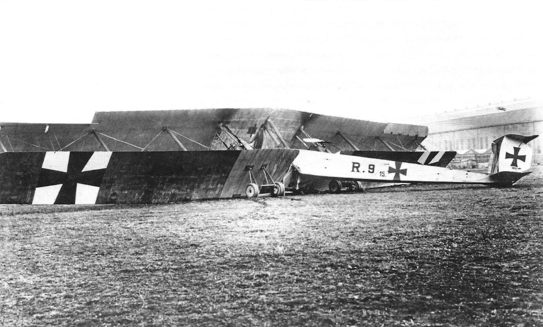
Construction on VGO.II began in December 1914, the same month that design of the VGO.I was completed. The VGO.II was completed in August and first flew on 25 October 1915. It was the first Staaken accepted by the Army (the Navy had accepted VGO.I) on 28 November and given Idflieg serial number R.9/15.
The VGO.I has not yet flown when construction on VGO.II began, so without flight-test experience it is not surprising that the VGO.II closely resembled the earlier aircraft. There were a number of detail differences, such as the radiators, but the most visible was a modest redesign of the tail surfaces. The horizontal tail surfaces remained the same but the gap between these biplane surfaces was greatly increased and taller rudders were fitted, but the number of rudders was reduced to two instead of four. Later a central fin was added for more stability.
The same type of engines were installed, the ill-fated Maybach HS engines that caused so much trouble in the VGO.I. However, because that aircraft had not yet flown the problems with the HS engines were still in the future.
Machine-gun positions were installed in the nose of the engine nacelles and additional defensive machine guns were fitted aft of the wings above and below the fuselage; these were present in subsequent Staakens.
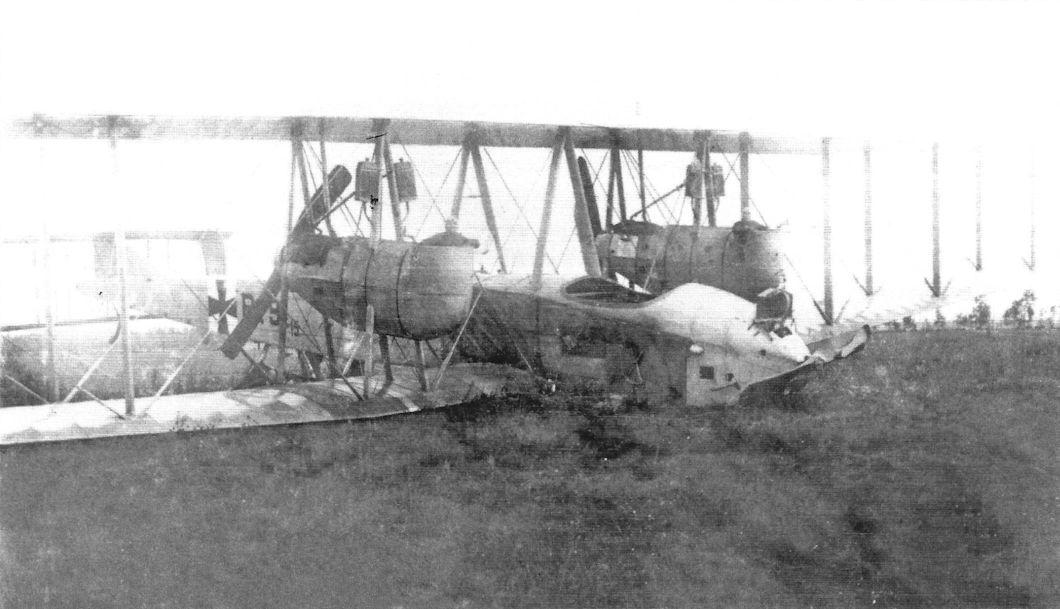
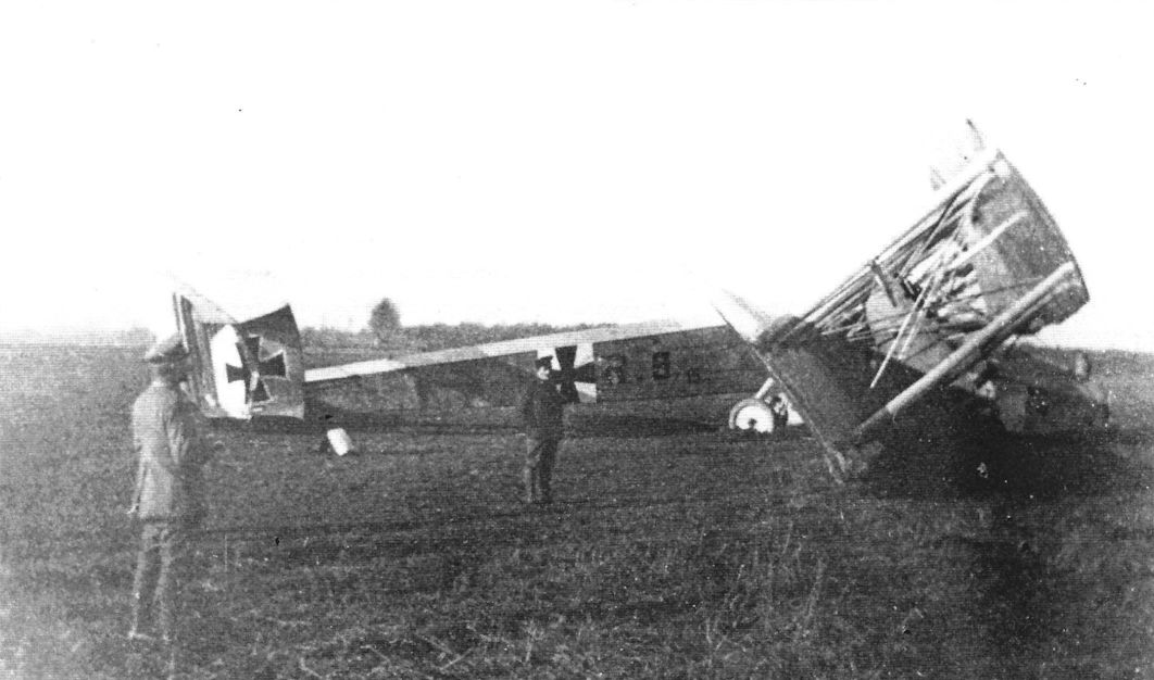
In February 1916 the R.9 was flown from Doberitz to Rfa 500 at Alt-Auz via Konigsberg. This time the delivery flight was successful; the R.9 flew the 900 km in 7 1/2 hours despite occasional snow showers and low overcast that forced it down to 100 m for much of the flight. Once at Rfa 500, Off-stv. Selmer piloted the VGO.II on a number of operational test flights. He claimed VGO.II bombed Russian targets as early as March 1916, but there is no substantiating documentation. The first known operational flight was on 13 August 1916, when VGO.II successfully bombed the rail junction at Schlok. On that flight VGO.II carried a useful load of 2,296 kg and reached an altitude of 2,500 m. Other missions followed. In late 1916 strong headwinds developed while VGO.II was returning home from a bombing mission and its fuel ran out 40 km short of its airfield. Fortunately, VGO.II was able to land safely on a small fighter airfield near Mitau. However, as it rolled to a stop it ran into a ditch, tearing off the undercarriage. Despite this mishap, the VGO.II was not damaged other than one broken strut! Within a few days repairs were completed and the crew flew the aircraft back to base.
Sikorski's Ilya Mourometz is known as the first bomber with a tail turret. However, a trial was flown with a gunner in the tail of VGO.II. This ended badly; the fuselage was too flexible. As a result the tail oscillated badly and the gunner experienced severe air-sickness.
Another trial was installation of a downward-firing 130 mm cannon. There was more than one desired result. First, it was expected that the high speed of the shell would result in more accuracy than just dropping bombs. Second, it was hoped that the cannon could penetrate the deck armor on British battleships. Unfortunately, test-firings from 800 meters above the surface resulted in a typical miss distance of 40-45 m, hardly the pin-point accuracy hoped for. At least recoil was demonstrated to be insignificant, the VGO.II absorbing it easily after its airframe was strengthened.
As newer Staaken bombers were delivered, the VGO.II was retired from active service to become a training aircraft. In that role it gave good service until it crashed in the summer of 1917.
Staaken Specifications
Type V.G.O I (R.M.L.1) V.G.O I (5 Eng. Ver.) V.G.O. II
Engines 3x240 Hp Maybach HS 4x245 Hp Maybach Mb.IVa & 2 160 Hp Mercedes D.III OR 5x245 Hp Maybach Mb.IVa 3x240 Hp Maybach HS (or Mb.IV)
Span 42.2 m (138' 5 1/2") 42.2 m (138' 5 1/2") 42.2 m (138'5 1/2")
Chord (inner) - - 4.6 m (15' 1")
Chord (outer) - - 3.6 m (11' 10")
Length 24 m (78'9") 24 m (78'9") 23.78 m (78'0")
Height 6.6 m (21' 7 1/2”) 6.6 m (21'7 1/2") 6.8 m (22' 3 1/2")
Tail span - - 9 m (29' 6")
Wing Area 332 m2 (3,572 ft2) 320 m2 (3,443 ft2) 332 m2 (3,572 ft2)
Wt. Empty 6,520 kg (14,377 lb.) 7,450 kg (16,427 lb.) 6,637 kg (14,635 lb.)
Wt. Fuel - - 1,126 kg (2,483 lb.)
Wt. Payload - - 2,440 kg (5,380 lb.)
Wt. Loaded 9,520 kg (20,992 lb.) 11,485 kg (25,325 lb.) 10,203 kg (22,498 lb.)
Max Speed 110 km/h (68.4 mph) 130 km/h (80.8 mph) -
Climb 2,000 m 39 minutes - -
Ceiling 3,000 m 79 minutes 60 minutes -
As war approached, Count Zeppelin turned his interest to heavy bombers as he realized the airship was a vulnerable and fragile weapon whose main use would be for reconnaissance. Two paths were chosen to move forward, wood construction and metal construction. Development of large metal bombers was entrusted to designer Claude Dornier and spun off to the Lindau facility.
To get a bomber in the air as fast as possible, conventional wood construction was pursued at another facility owned by Zeppelin. A new company called Versuchsbau G.m.b.H. Gotha-Ost (VGO - Experimental Works Gotha-East) was founded by Zeppelin and Bosch and buildings were rented on the Gotha airfield for space to assemble the wooden bomber. Remarkably, work on the new bomber was started in September 1914, less than eleven years after the Wright's first flight. The new giant bomber was a private venture and such was the urgency to complete it that its design had not been completed before construction began. In fact, construction had to be suspended in January 1915 pending arrival of the new 240 hp Maybach HS engines. Derived from airship engines, the new engines proved unsuccessful in the more demanding role as aircraft engines.
In addition to the design not being completed until December 1914, two months after the start of construction, there were other challenges. The Prussian War Office was not happy with the concept of a private venture and was not supportive of Zeppelin's effort. The start of the war in August caused serious shortages of skilled labor in all industries and raw materials were difficult to procure. Exacerbating all these issues was the bomber's unprecedented size. Despite these challenges, the VGO.I first flew on April 11, 1915.
Notwithstanding the aircraft's 1914 inception, the basic size, construction, and configuration of the VGO.I were successful enough that they were retained by Staaken designs throughout the war - and the Staaken designs were the most successful Giant bomber family designed in Germany.
Flight testing revealed an often under-appreciated challenge; the aircraft was so large and noisy, and the crew were so spread out, that crew coordination was a serious difficulty that impeded flight operations and sometimes compromised flight safety.
The VGO.I was an enormous biplane of conventional wood construction. It had three engines; one with tractor propeller in the nose and one in a nacelle between the wings on each side mounted in as a pusher. The VGO.I differed most noticeably from typical designs in its biplane tail surfaces, nose-wheel under-carriage, and huge size; smaller biplanes of the time almost invariably used a tail-skid instead of nose wheels and typically did not have biplane tails. However, a tail-skid was fitted in case of rough landings.
In accordance with its design role, the VGO.I had a bomb bay at its center of gravity large enough to carry a 1,000 kg bomb and provision was made for flexible defensive machine guns above and below the fuselage and in the front of the engine nacelles. The nacelle guns were to be fitted for the engine mechanics; to enable in-flight repairs thought to be necessary to sustain dependable high-endurance flight given the modest reliability of engines of the time. Provision for mechanics to move to the engine nacelles and spend time there was essential.
The VGO.I had good flying qualities. However, its new Maybach HS engines were a constant source of problems and slowed development of the R-plane programs using it, including that of the VGO.I. Until that engine, Maybach had focused on airship engines. These are not as highly stressed as airplane engines and in airships normally need to produce full power for relatively short periods on time. In contrast, aircraft engines need to provide maximum power for takeoff and the prolonged climb to cruise altitude, and in cruise flight have to produce a higher percentage of rated power than airship engines. Learning these lessons, then addressing the problems successfully, was a difficult, time-consuming process and Maybach was not able to fully achieve this with the HS engine.
As a result of the engine development problems, the VGO.I did not have HS engines that were reliable enough to attempt the Navy's reliability tests. On December 15, 1915, while returning to Gotha, two of the three oil lines to the engines failed during a snowstorm. With only one engine running, a forced landing was inevitable. With great skill the pilots were able to land the VGO.I in a forest clearing; the aircraft was badly damaged but were no injuries to the crew.
The VGO.I was rebuilt after this accident and a number of improvements were added during this process, including enlarging and balancing the rudders for more rudder control authority. The VGO. II, which had already been completed by this time, already embodied many of these improvements. Unfortunately, one item not changed was the unreliable engines. The Maybach HS was still the most powerful aircraft engine available at the time and apparently a desperate hope its problems could be solved was still alive. Unfortunately, this hope was unfounded.
The re-built VGO.I was accepted by the Navy and given the designation RML.I for Reichs Marine Landflugzeug I (Reich Navy Landplane I). It left Gotha for Alt-Auz in June 1916 and its delivery flight, normally a three-day flight, turned into a two-month tragicomedy of errors. Some time in August the RML.I finally arrived at its destination and its first bombing raid was performed on August 15, 1916, after an aborted attempt on the 13th. According to the War Diary there were four bombing raids in all. By 1 September the VGO.I had been damaged by a crash when two of its three engines failed on take-off. The aircraft was saved from complete destruction by being cushioned by the trees of a pine forest.
The wings were destroyed but the fuselage was salvaged. Again the VGO.I, aka RML.I, was rebuilt. The untrustworthy Maybach HS engines were the root causes of the two crashes and were finally replaced. Because the VGO.I had been underpowered even when the HS engines were running, during the rebuild they were replaced with no less than five engines, in this case five 245 hp Maybach Mb.IVa engines. One was fitted in the nose and two were installed in each nacelle geared to drive a single four-bladed propeller. The tailplane was raised higher on the fuselage and the entire fuselage and tail were covered in transparent cellon in an experiment to produce stealth aircraft.
Although made by the same manufacturer, the new engines were far more reliable than their worthless predecessors and were the first overcompressed engines developed for high-altitude performance in Germany.
The rebuilt VGO.I, still under the control of the navy, was first flown on 10 March 1917. As it was circling the Staaken airfield after a smooth takeoff, there was a major explosion in the left nacelle and the propeller stopped. The pilots executed an excellent engine-out landing on the field. Unfortunately, the rudders jammed, a fault noticed three days previously but inexplicably not repaired before the flight, and when the power was cut on the remaining engines the airplane turned right on the runway and crashed into the airship shed. The pilot was killed instantly and another crewmember died of injuries within a few hours. The third time was a charm; after its third crash the VGO.I was finally destroyed and its story ended. Two days earlier Count Zeppelin had died.
VGO.II
Construction on VGO.II began in December 1914, the same month that design of the VGO.I was completed. The VGO.II was completed in August and first flew on 25 October 1915. It was the first Staaken accepted by the Army (the Navy had accepted VGO.I) on 28 November and given Idflieg serial number R.9/15.
The VGO.I has not yet flown when construction on VGO.II began, so without flight-test experience it is not surprising that the VGO.II closely resembled the earlier aircraft. There were a number of detail differences, such as the radiators, but the most visible was a modest redesign of the tail surfaces. The horizontal tail surfaces remained the same but the gap between these biplane surfaces was greatly increased and taller rudders were fitted, but the number of rudders was reduced to two instead of four. Later a central fin was added for more stability.
The same type of engines were installed, the ill-fated Maybach HS engines that caused so much trouble in the VGO.I. However, because that aircraft had not yet flown the problems with the HS engines were still in the future.
Machine-gun positions were installed in the nose of the engine nacelles and additional defensive machine guns were fitted aft of the wings above and below the fuselage; these were present in subsequent Staakens.
In February 1916 the R.9 was flown from Doberitz to Rfa 500 at Alt-Auz via Konigsberg. This time the delivery flight was successful; the R.9 flew the 900 km in 7 1/2 hours despite occasional snow showers and low overcast that forced it down to 100 m for much of the flight. Once at Rfa 500, Off-stv. Selmer piloted the VGO.II on a number of operational test flights. He claimed VGO.II bombed Russian targets as early as March 1916, but there is no substantiating documentation. The first known operational flight was on 13 August 1916, when VGO.II successfully bombed the rail junction at Schlok. On that flight VGO.II carried a useful load of 2,296 kg and reached an altitude of 2,500 m. Other missions followed. In late 1916 strong headwinds developed while VGO.II was returning home from a bombing mission and its fuel ran out 40 km short of its airfield. Fortunately, VGO.II was able to land safely on a small fighter airfield near Mitau. However, as it rolled to a stop it ran into a ditch, tearing off the undercarriage. Despite this mishap, the VGO.II was not damaged other than one broken strut! Within a few days repairs were completed and the crew flew the aircraft back to base.
Sikorski's Ilya Mourometz is known as the first bomber with a tail turret. However, a trial was flown with a gunner in the tail of VGO.II. This ended badly; the fuselage was too flexible. As a result the tail oscillated badly and the gunner experienced severe air-sickness.
Another trial was installation of a downward-firing 130 mm cannon. There was more than one desired result. First, it was expected that the high speed of the shell would result in more accuracy than just dropping bombs. Second, it was hoped that the cannon could penetrate the deck armor on British battleships. Unfortunately, test-firings from 800 meters above the surface resulted in a typical miss distance of 40-45 m, hardly the pin-point accuracy hoped for. At least recoil was demonstrated to be insignificant, the VGO.II absorbing it easily after its airframe was strengthened.
As newer Staaken bombers were delivered, the VGO.II was retired from active service to become a training aircraft. In that role it gave good service until it crashed in the summer of 1917.
Staaken Specifications
Type V.G.O I (R.M.L.1) V.G.O I (5 Eng. Ver.) V.G.O. II
Engines 3x240 Hp Maybach HS 4x245 Hp Maybach Mb.IVa & 2 160 Hp Mercedes D.III OR 5x245 Hp Maybach Mb.IVa 3x240 Hp Maybach HS (or Mb.IV)
Span 42.2 m (138' 5 1/2") 42.2 m (138' 5 1/2") 42.2 m (138'5 1/2")
Chord (inner) - - 4.6 m (15' 1")
Chord (outer) - - 3.6 m (11' 10")
Length 24 m (78'9") 24 m (78'9") 23.78 m (78'0")
Height 6.6 m (21' 7 1/2”) 6.6 m (21'7 1/2") 6.8 m (22' 3 1/2")
Tail span - - 9 m (29' 6")
Wing Area 332 m2 (3,572 ft2) 320 m2 (3,443 ft2) 332 m2 (3,572 ft2)
Wt. Empty 6,520 kg (14,377 lb.) 7,450 kg (16,427 lb.) 6,637 kg (14,635 lb.)
Wt. Fuel - - 1,126 kg (2,483 lb.)
Wt. Payload - - 2,440 kg (5,380 lb.)
Wt. Loaded 9,520 kg (20,992 lb.) 11,485 kg (25,325 lb.) 10,203 kg (22,498 lb.)
Max Speed 110 km/h (68.4 mph) 130 km/h (80.8 mph) -
Climb 2,000 m 39 minutes - -
Ceiling 3,000 m 79 minutes 60 minutes -
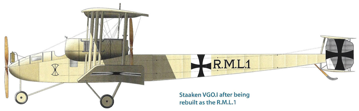
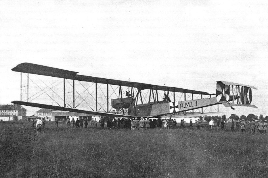
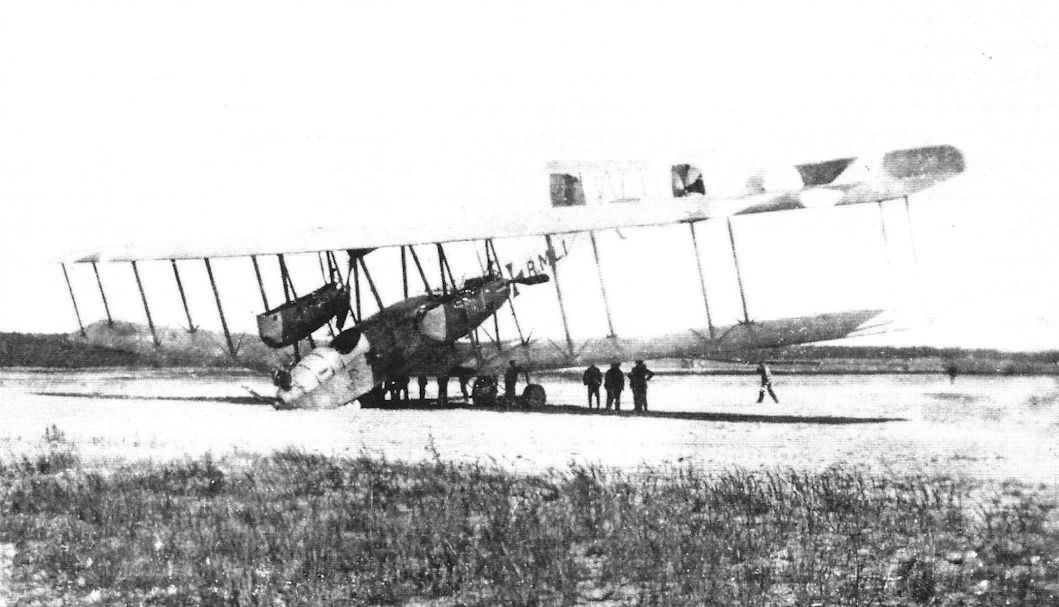
Staaken VGO.I after being rebuilt as the R.M.L.1

Staaken VGO.I in final configuration with partial Cellon covering.
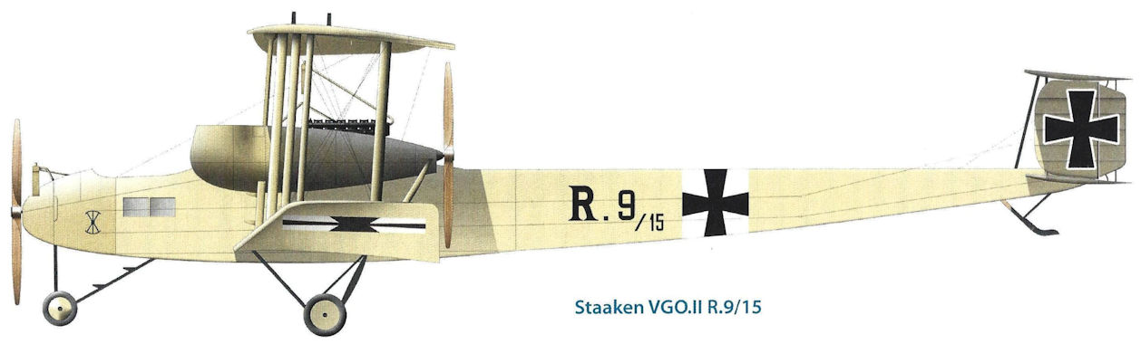
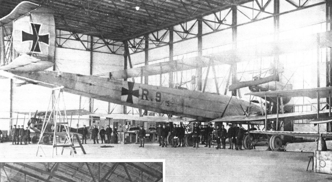
Staaken VGO.II R.9/15
Staaken's first R-plane (R for Reisenflugzeug, or Giant airplane), the VGO.I in its original configuration; a Halberstadt B.I at right and the men give scale to the aircraft.The basic configuration, the wings, and the horizontal tail remained basically unchanged for Staaken bombers throughout the war. Note the four short fins and rudders. Amazingly, design of this aircraft began in December 1914, just 11 years after the first flight of the Wright brothers. Its wing span of 138.5' exceeded the 120' distance of the Wright's first flight. Each of its three propellers was powered by a 240 hp Maybach HS engine. Designed for airships, the HS engines were unreliable in airplanes due to the higher average power airplanes needed. (Peter M. Grosz collection/STDB)
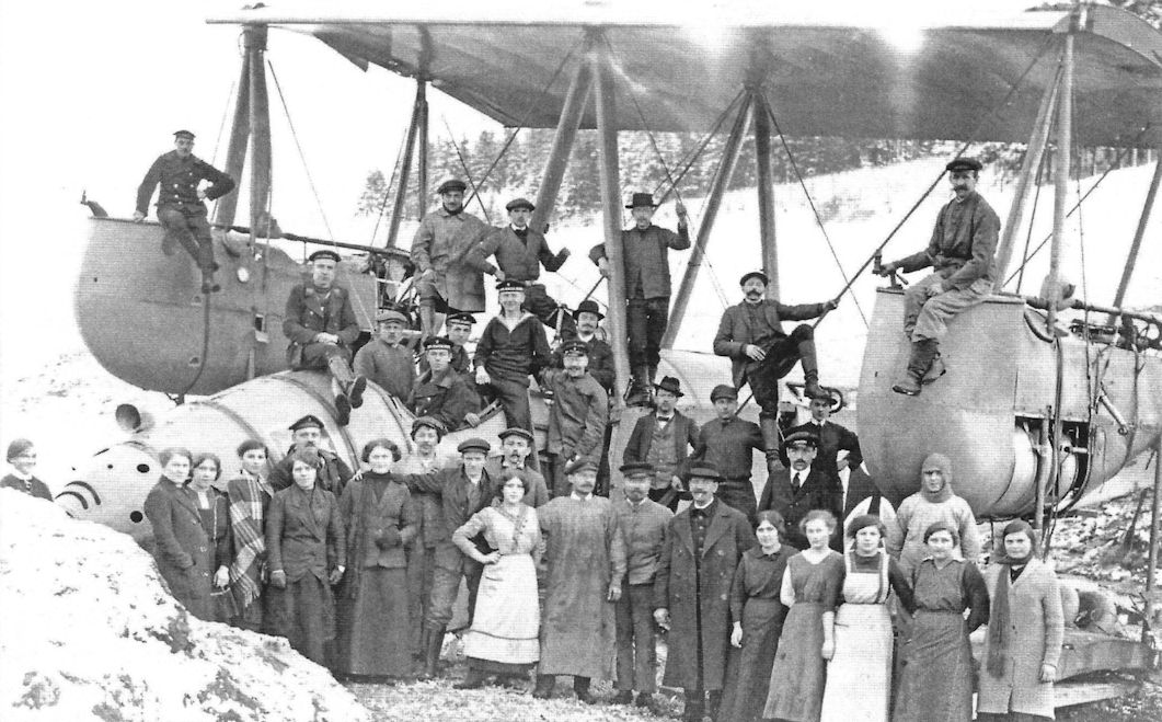
All three VGO aircraft have been built at Versuchsbau Gotha Ost. Here is shown the VGO.I before reconstruction. Later, as "R.M.L.1", it got movable machine guns in the engine nacelles operated by the mechanics. A series of crash landings, due to the too weak and overtaxed engines resulted in a series of rebuilds. Instead of three 240 hp Maybach HS engine the improved VGO.I had 4 245 hp Maybach Mb.IVa and two 160 hp Mercedes D.III engines in the nose. Finally, after a brief service at the front in 1916 as a naval bomber, the VGO.I was reengined by five 245 hp Maybach Mb.IVa. During the first flight after the final rebuild on March 10,1917, the left engine failed. Vollmoller had to push hard on the rudder, which jammed in the final position, and the aircraft turned to the right toward the hangar. Karl Kuring, another test pilot, had already complained days before that the lateral control was not working properly, recognized the danger and tried to pull the pedal into the normal position with his hands, but too late, the plane crashed into the hangar, testpilots Vollmoller and Gustav Klein were dead.
All three VGO aircraft have been built at Versuchsbau Gotha Ost. Here is shown the VGO.I before reconstruction. Later, as "R.M.L.1", it got movable machine guns in the engine nacelles operated by the mechanics. A series of crash landings, due to the too weak and overtaxed engines resulted in a series of rebuilds. Instead of three 240 hp Maybach HS engine the improved VGO.I had 4 245 hp Maybach Mb.IVa and two 160 hp Mercedes D.III engines in the nose. Finally, after a brief service at the front in 1916 as a naval bomber, the VGO.I was reengined by five 245 hp Maybach Mb.IVa. During the first flight after the final rebuild on March 10,1917, the left engine failed. Vollmoller had to push hard on the rudder, which jammed in the final position, and the aircraft turned to the right toward the hangar. Karl Kuring, another test pilot, had already complained days before that the lateral control was not working properly, recognized the danger and tried to pull the pedal into the normal position with his hands, but too late, the plane crashed into the hangar, testpilots Vollmoller and Gustav Klein were dead.
Staaken's first R-plane, the VGO.I. The overall configuration was conventional, if very large, for its time. The double interplane cables are faired without first being drawing together as they were on all later types. VGO engineers are standing in front of the aircraft; from left to right they are Hans Baumeister, Philipp Simon, and Foreman Hungs. (Peter M. Grosz collection/STDB)
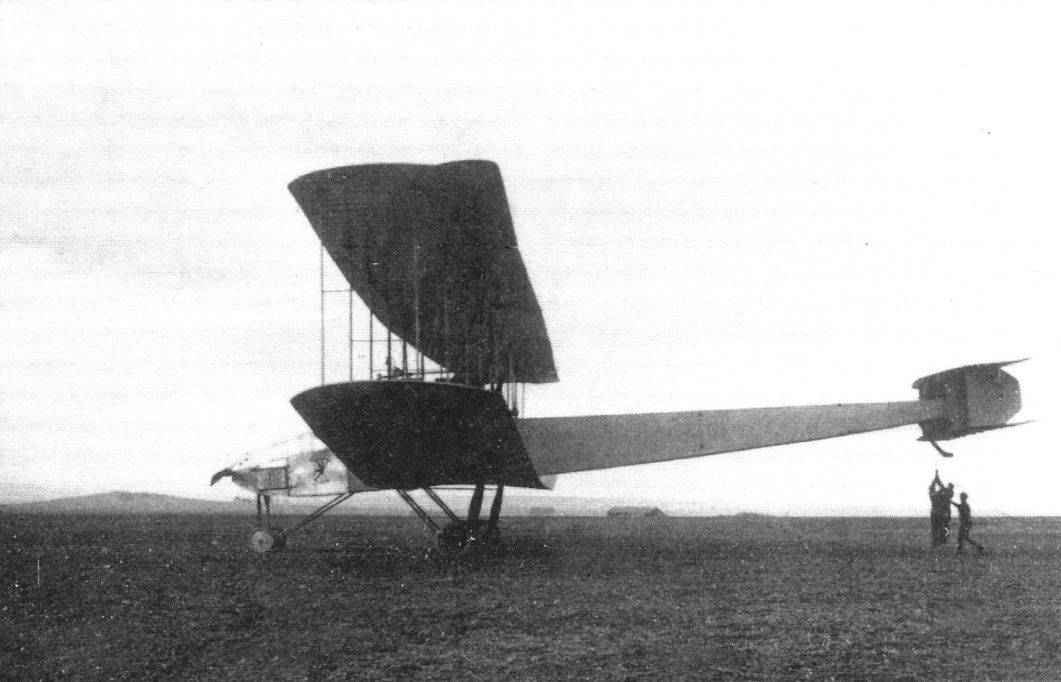
Staaken's first R-plane, the VGO.I. The V.G.O. It normally operated on its nose landing gear but it also had a tail skid in case it needed one, as shown here. (Peter M. Grosz collection/STDB)
Staaken's first R-plane, the VGO.I in its original configuration; the men give scale to the aircraft. The basic configuration, the wings, and the horizontal tail remained basically unchanged throughout the war. The aft engine cowling panels are not yet fitted. (Peter M. Grosz collection/STDB)
Staaken's first R-plane, the VGO.I. The V.G.O. It normally operated on its nose landing gear but it also had a tail skid in case it needed one, as shown here. (Peter M. Grosz collection/STDB)
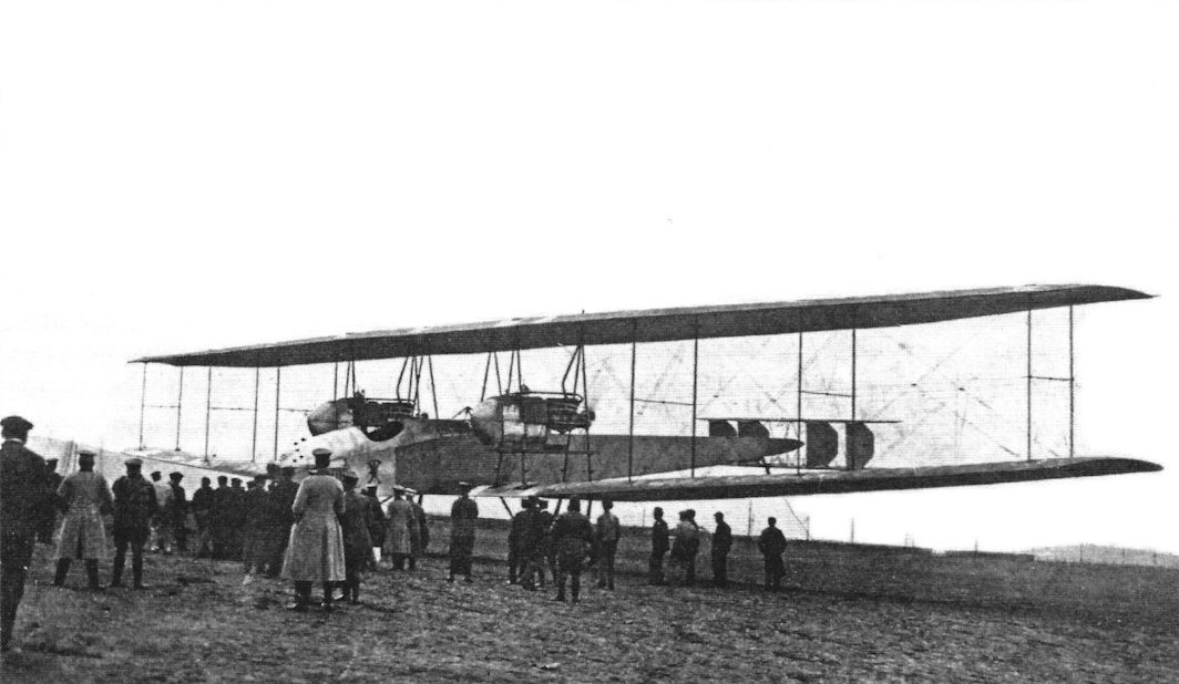
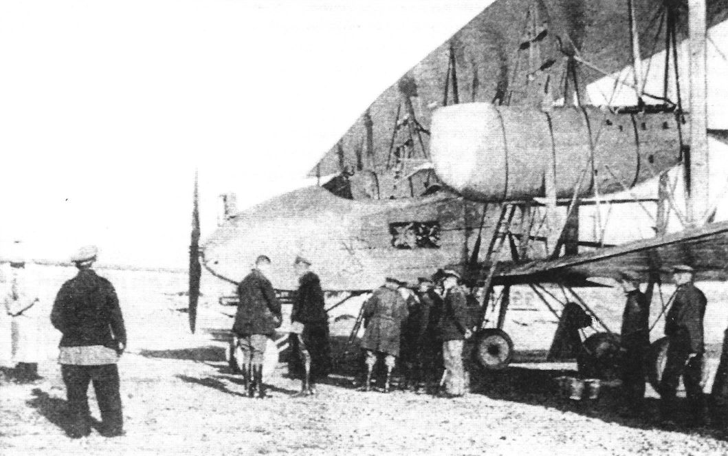
Staaken's first R-plane, the VGO.I under inspection by a group of men, probably VIPs. (Peter M. Grosz collection/STDB)
Staaken's first R-plane, the VGO.I. The 240 hp Maybach HS engines fitted were the most powerful aeroengines available in Germany at the time, but they were very unreliable and significantly hindered R-plane development. (Peter M. Grosz collection/STDB)
Staaken's first R-plane, the VGO.I. The tail configuration included four small fins and rudders. Here the wing-mounted engines are running without their aft cowlings, making the engines visible. (Peter M. Grosz collection/STDB)
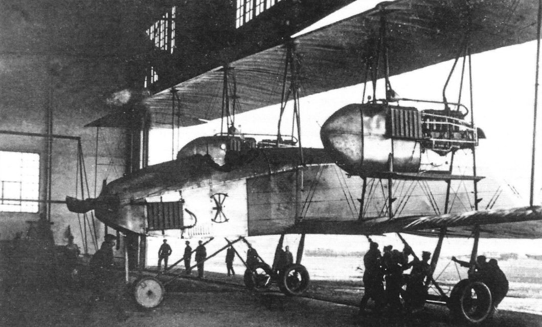
Staaken's first R-plane, the VGO.I in the hangar in its original configuration without aft engine cowlings. (Peter M. Grosz collection/STDB)
Staaken's first R-plane, the VGO.I, in its initial configuration with four short fins and rudders and missing aft engine cowlings. (Peter M. Grosz collection/STDB)
Staaken's first R-plane, the VGO.I. The 240 hp Maybach HS engines fitted were the most powerful aeroengines available in Germany at the time, but they were very unreliable and significantly hindered R-plane development. (Peter M. Grosz collection/STDB)
Staaken's first R-plane, the VGO.I in its original configuration; the men give scale to the aircraft. The basic configuration, the wings, and the horizontal tail remained basically unchanged throughout the war. The aft engine cowling panels are not yet fitted. (Peter M. Grosz collection/STDB)
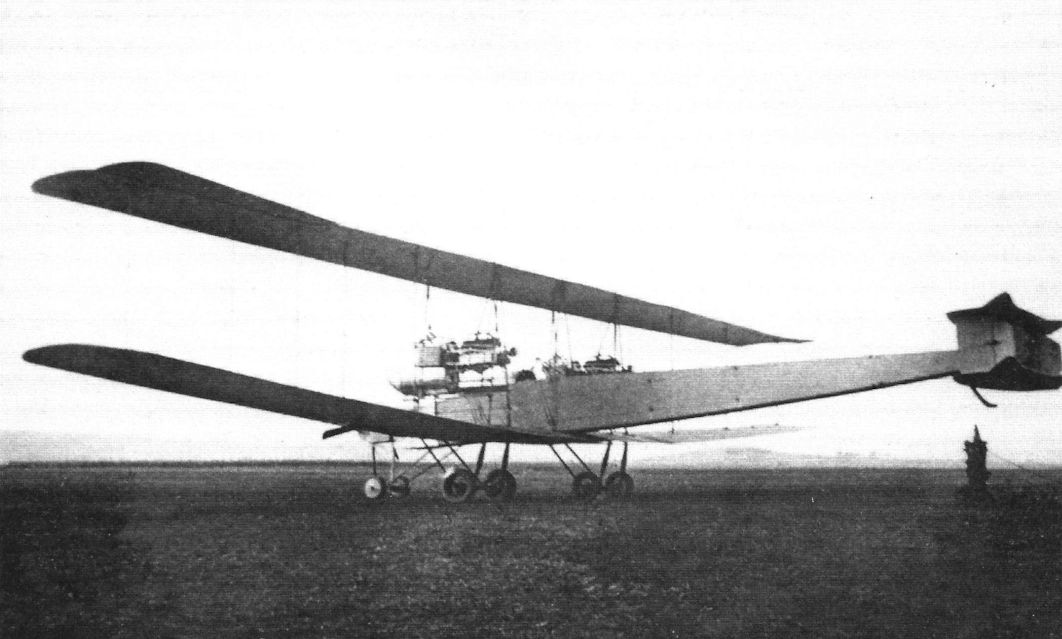
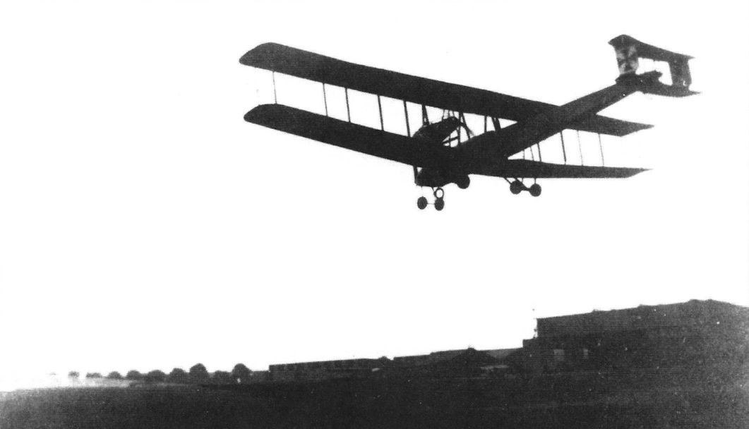
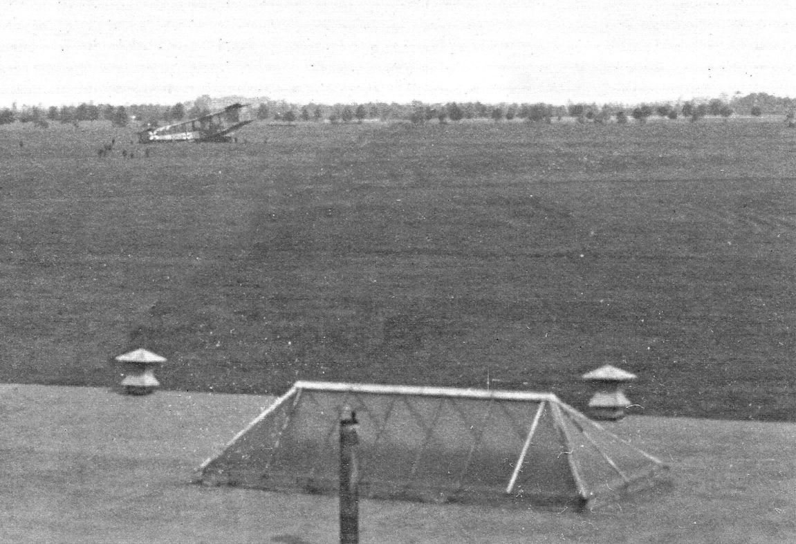
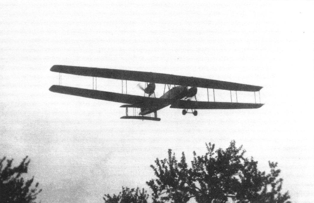
Staaken's first R-plane, the VGO.I, on its maiden flight on April 11, 1915. (Peter M. Grosz collection/STDB)
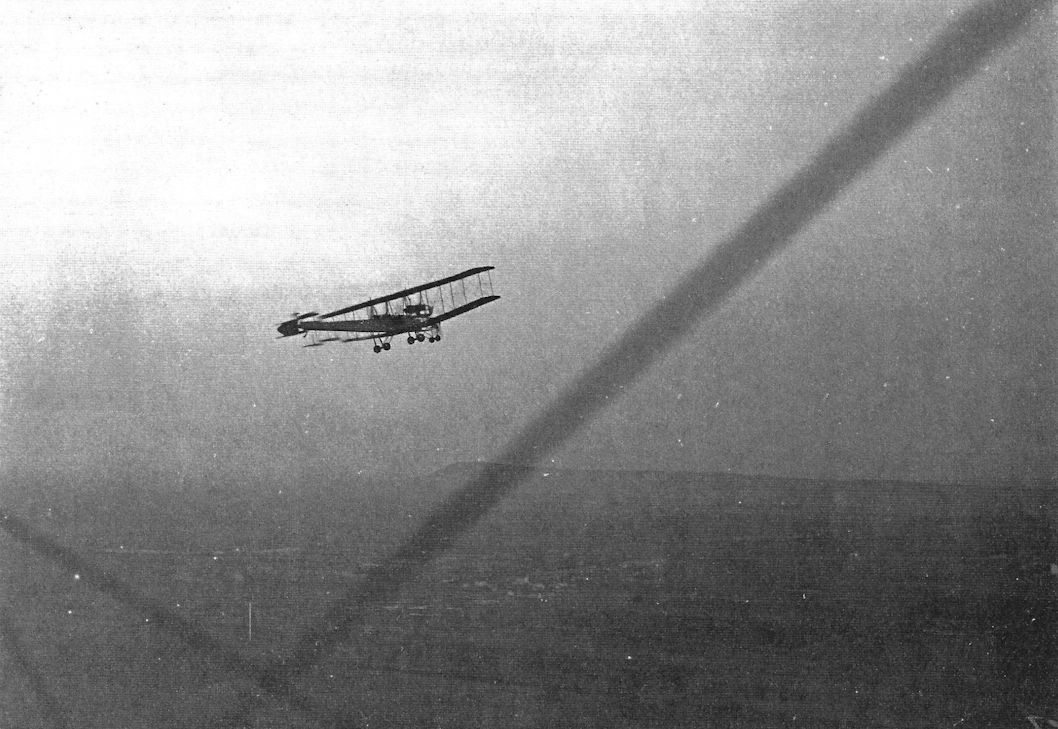
Staaken's first R-plane, the VGO.I photographed in flight from another aircraft. (Peter M. Grosz collection/STDB)
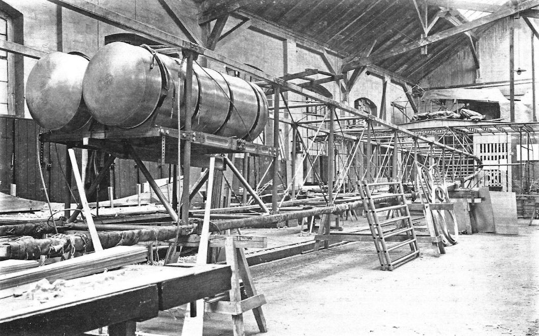
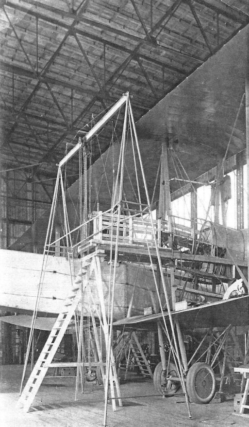
The V.G.O. I being modified in the factory. (Peter M. Grosz collection/STDB)
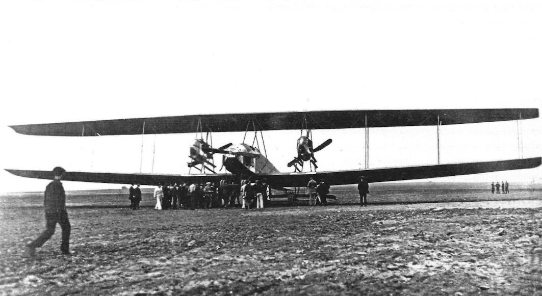
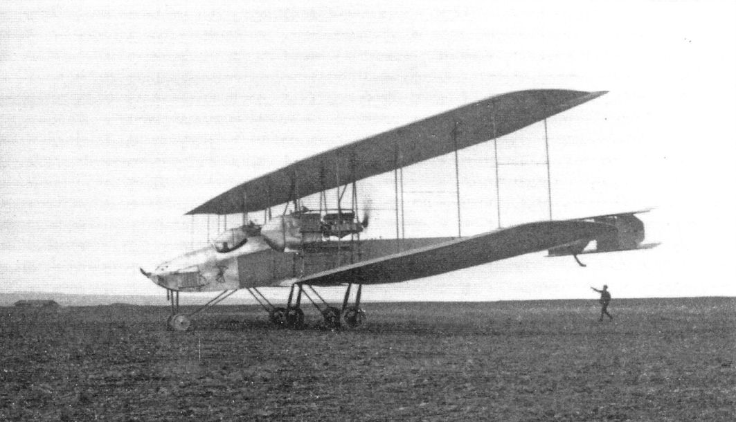
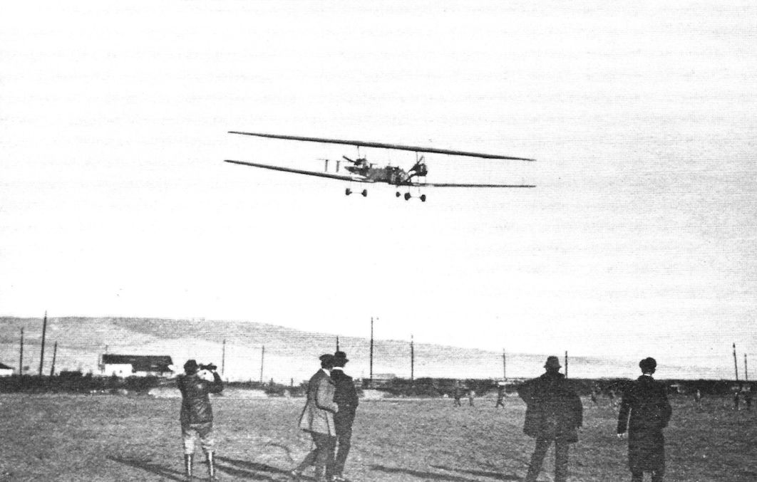
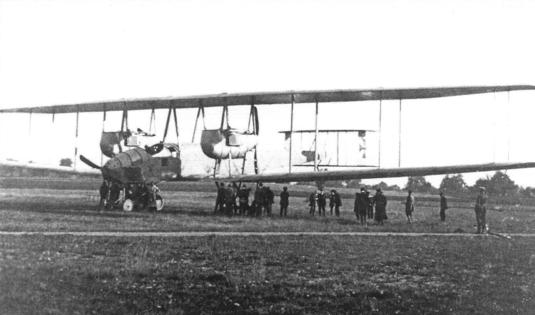
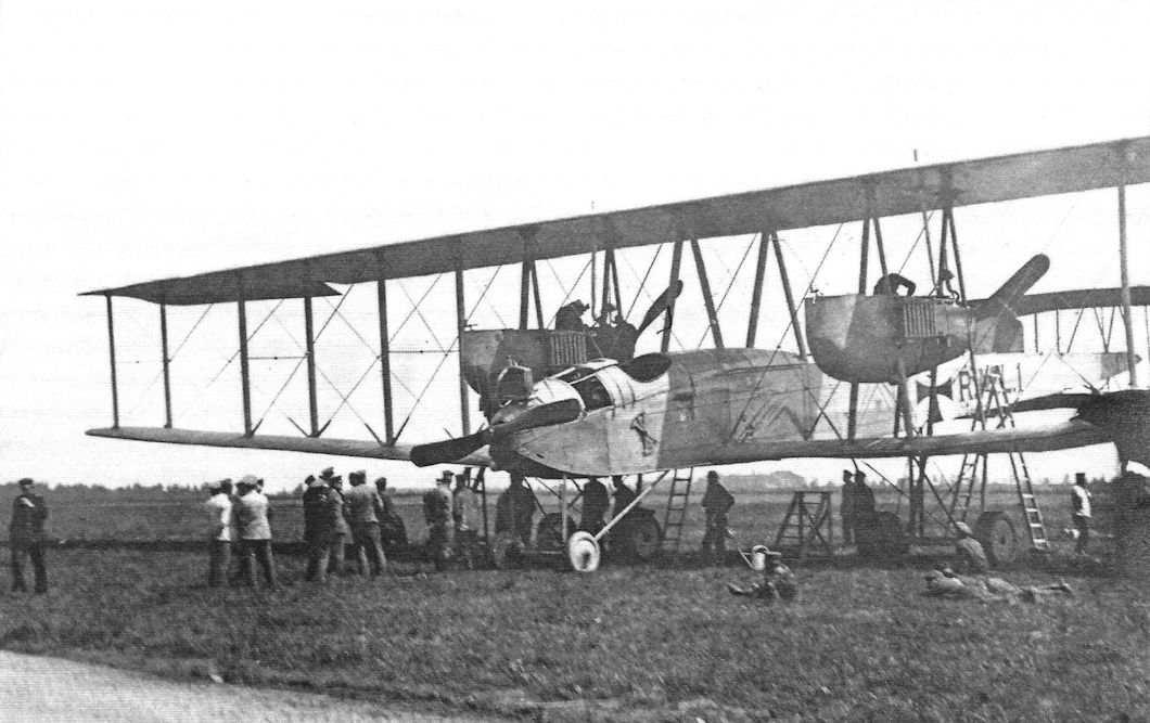
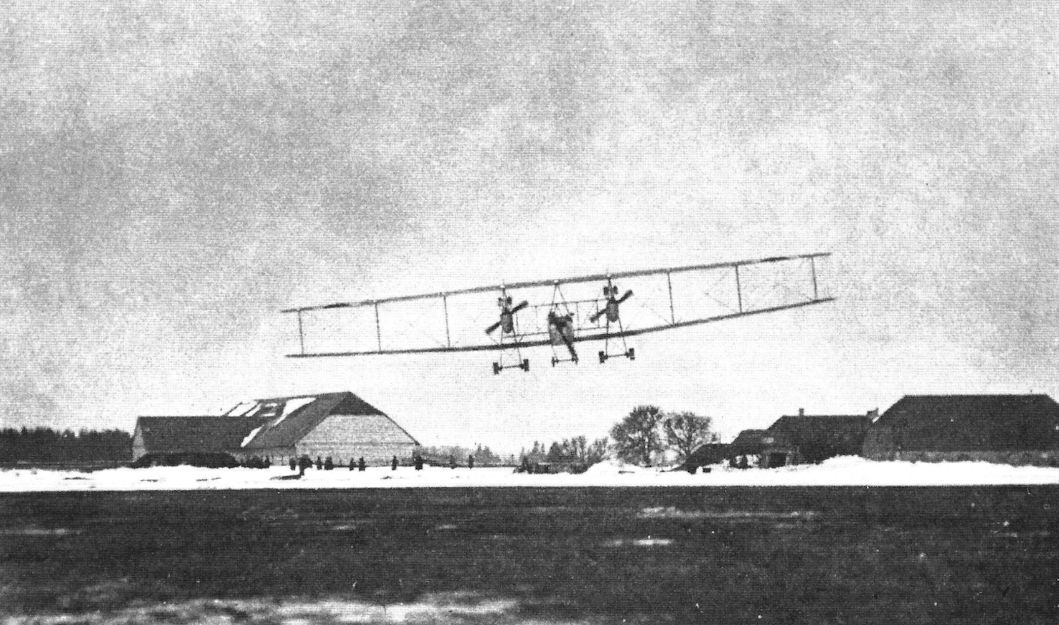
The VGO.I in the autumn of 1915 after the engine nacelles were modified and the four short fins and rudders replaced by two tall fins and rudders. (Peter M. Grosz collection/STDB)
The VGO.I in the autumn of 1915 after the engine nacelles were modified and the four short rudders and fins replaced by two tall fins and rudders. (Peter M. Grosz collection/STDB)
The VGO.I in the autumn of 1915 after the engine nacelles were modified and the four short fins and rudders replaced by two tall fins and rudders. (Peter M. Grosz collection/STDB)
The VGO.I in the autumn of 1915 after the engine nacelles were modified and the four short fins and rudders replaced by two tall fins and rudders. (Peter M. Grosz collection/STDB)
The VGO.I in the autumn of 1915 after the engine nacelles were modified and the four short fins and rudders replaced by two tall fins and rudders. (Peter M. Grosz collection/STDB)
The V.G.O.I after modifications. There are now two tall fins and rudders. An Albatros B.II is in left foreground. (Peter M. Grosz collection/STDB)
The VGO.I in the autumn of 1915 after the engine nacelles were modified and the four short fins and rudders were replaced by two taller fins and rudders. (Peter M. Grosz collection/STDB)
The VGO.I in the autumn of 1915 after the engine nacelles were modified and the four short fins and rudders were replaced by two taller fins and rudders. (Peter M. Grosz collection/STDB)
The VGO.I in the autumn of 1915 after the engine nacelles were modified and the four short fins and rudders were replaced by two taller fins and rudders. (Peter M. Grosz collection/STDB)
The V.G.O.I after modifications. (Peter M. Grosz collection/STDB)
The VGO.I after it crashed in the Thuringen Forest on 15 December 1915. (Peter M. Grosz collection/STDB)
The VGO.I after it crashed in the Thuringen Forest on 15 December 1915. The crash severely damaged the aircraft but there were no injuries to the crew. (Peter M. Grosz collection/STDB)
The VGO.I after it crashed in the Thuringen Forest on 15 December 1915. The crash was caused by failure of two engines after their oil lines failed during a severe snowstorm. Unable to maintain altitude on one engine, pilots Hans Vollmoller and Flugmaat Willy Mann skillfully landed in a small forest clearing with no injuries to the crew. (Peter M. Grosz collection/STDB)
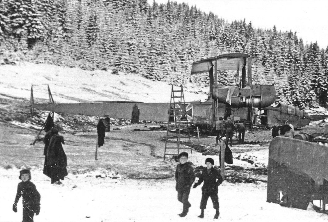
The VGO.I after it crashed in the Thuringen Forest. Here it is being dismantled to move the parts back to the factory to rebuild the aircraft. (Peter M. Grosz collection/STDB)
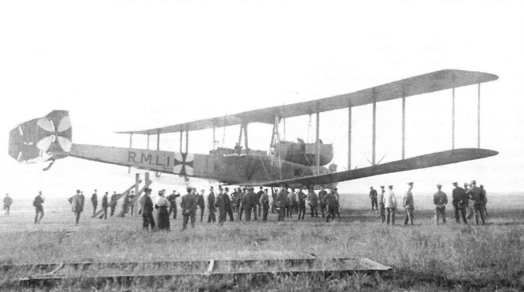
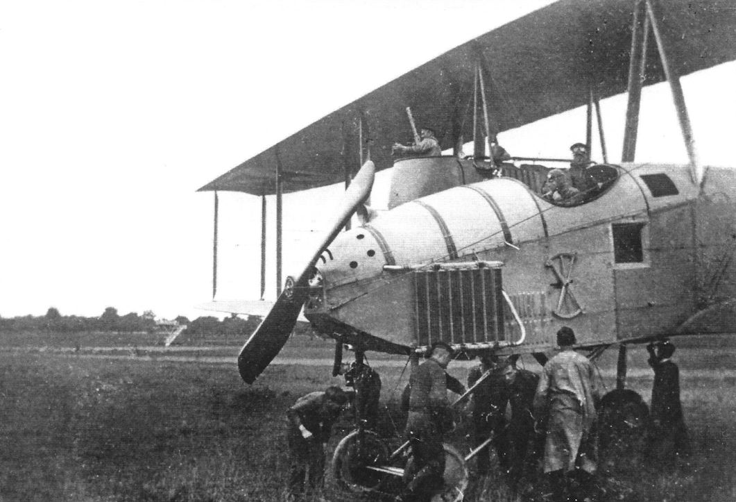
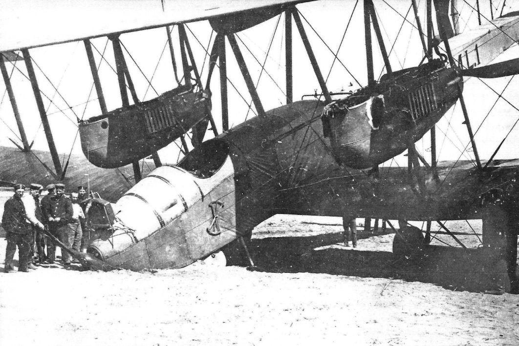
The VGO.I was rebuilt after it crashed in the Thuringen Forest. It included some modifications that had already be applied to the VGO.II, which had been completed by this time. The rebuilt VGO.I was assigned to the Navy as the R.M.L.1 (Reichs Marine Landflugzeug 1 = Reich Navy Landplane 1).The designation was painted on both sides of the fuselage in large characters. The rebuilt VGO.I now featured flexible machine gun positions in the forward part of the rebuilt engine nacelles. A large gravity fuel tank was added to the underside of the upper wing and became a feature of later Zeppelin-Staaken designs. The fins were enlarged and the rudders were aerodynamically balanced. (Peter M. Grosz collection/STDB)
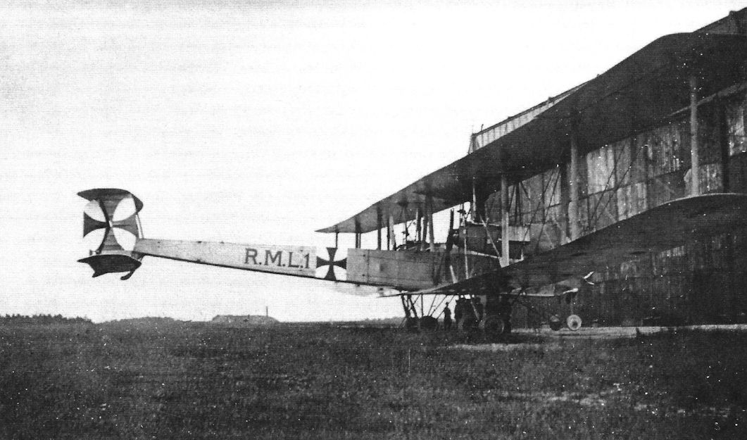
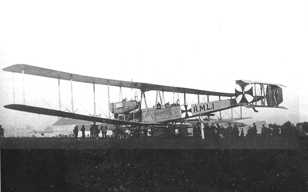
The VGO.I after being rebuilt as the R.M.L.1. (Peter M. Grosz collection/STDB)
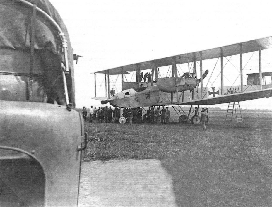
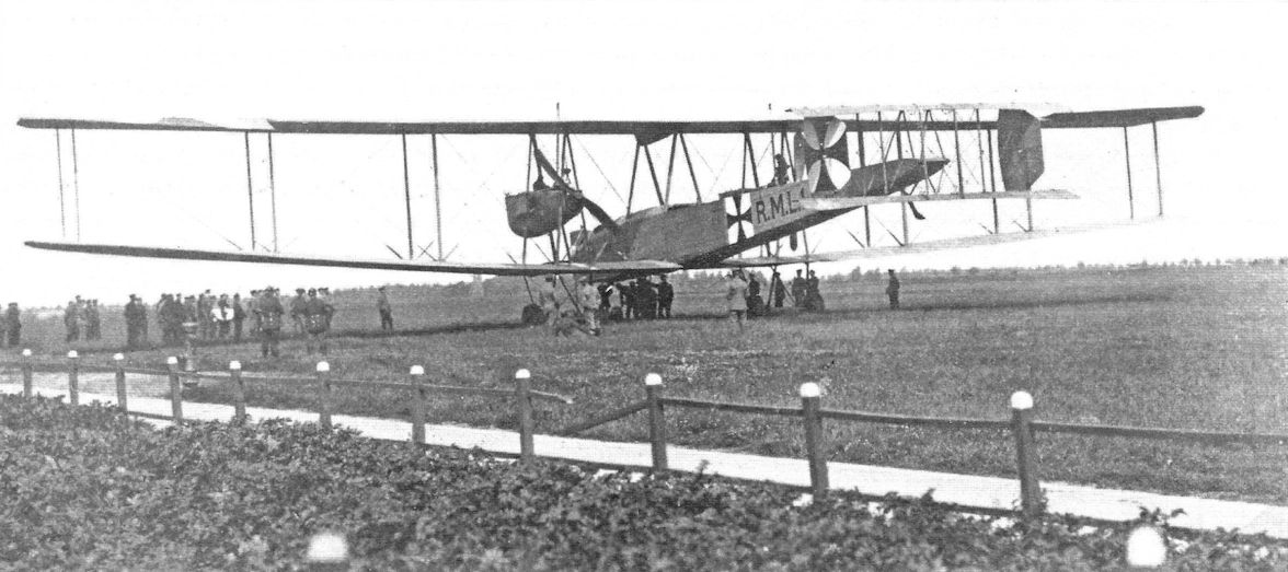
The VGO.I/R.M.L.1 on an airfield. (Peter M. Grosz collection/STDB)
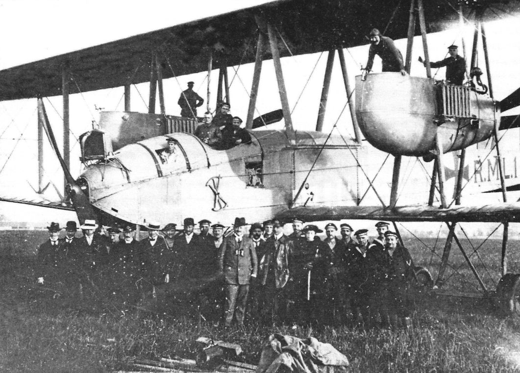
The VGO.I after being rebuilt as the R.M.L.1. (Peter M. Grosz collection/STDB)
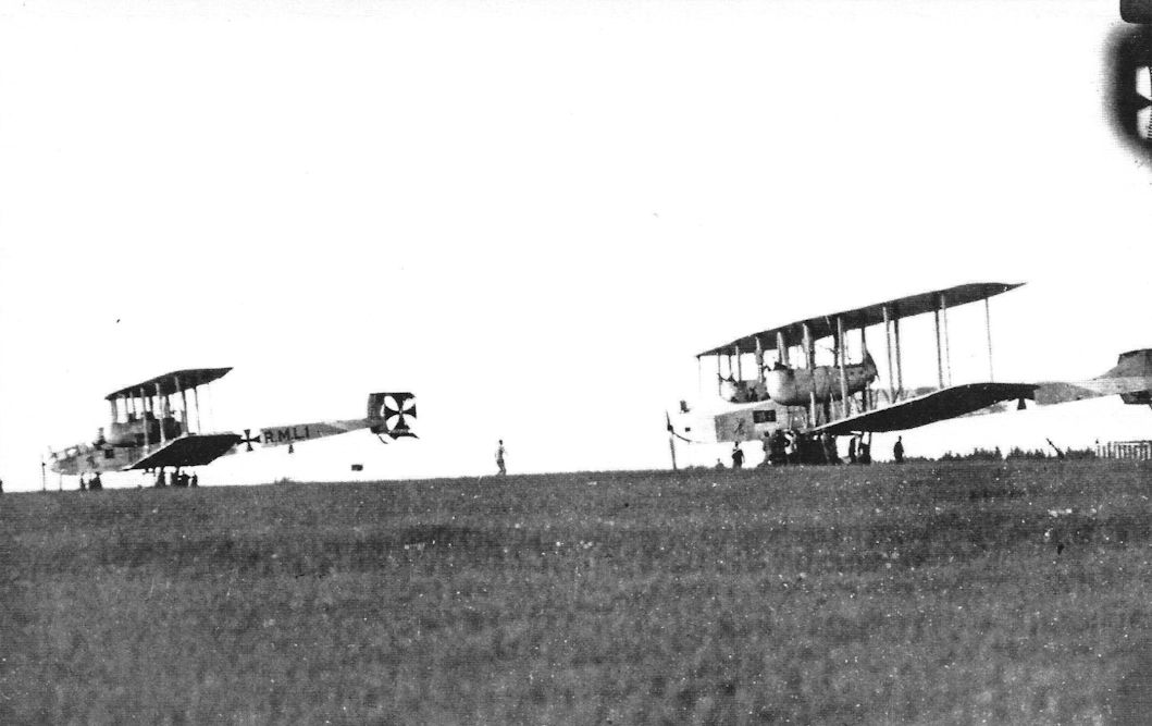
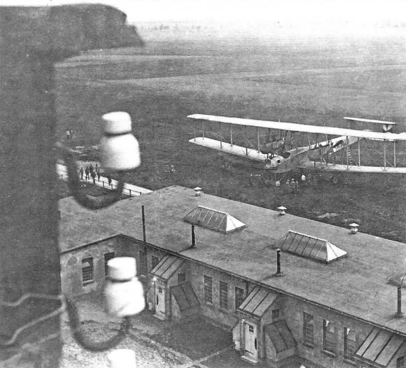
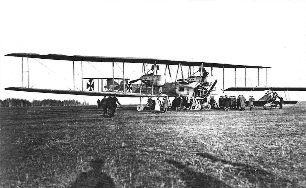
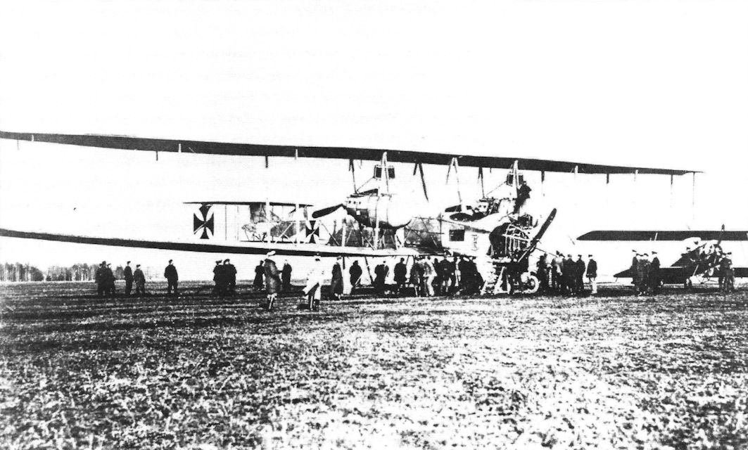
The VGO.II (R.9/15) at right and the R.M.L.1 on the airfield together.The location is probably Alt-Auz on the Eastern Front. (Peter M. Grosz collection/STDB)
The VGO.I after being rebuilt as the R.M.L.1. (Peter M. Grosz collection/STDB)
The RML.I as used on operations over the Eastern Front.
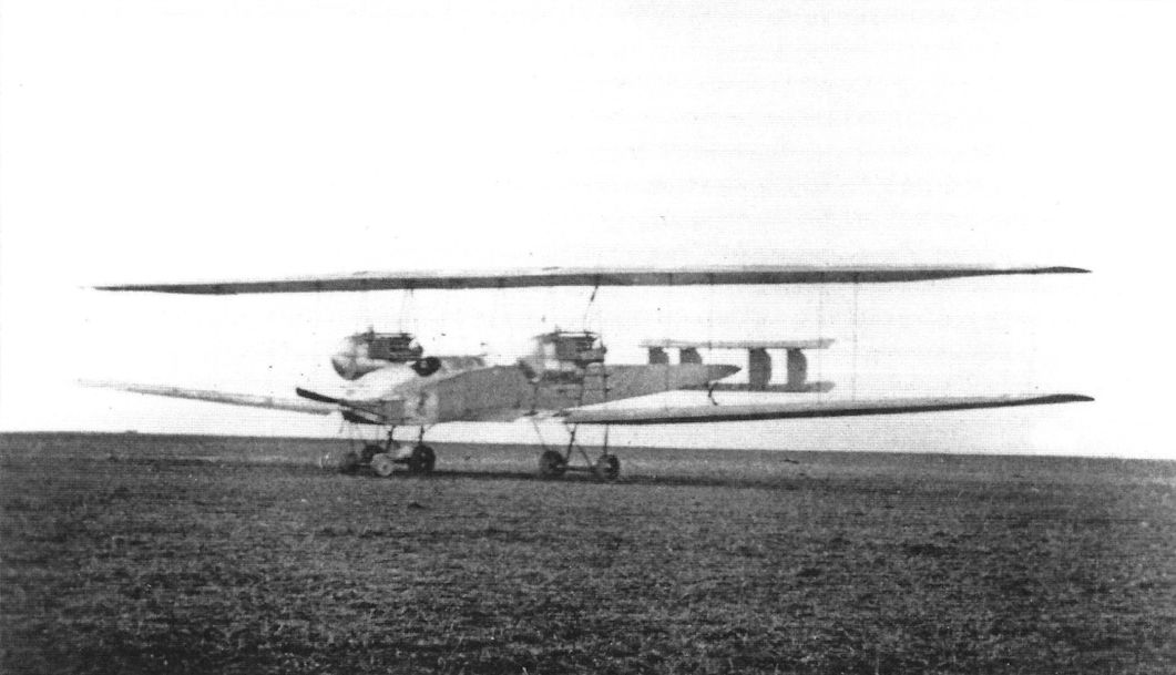
The VGO.I after its final rebuild with two 245 hp Maybach Mb.IVa engines in each wing nacelle. (Peter M. Grosz collection/STDB)
The VGO.I/R.M.L.1 has experienced a taxi accident. (Peter M. Grosz collection/STDB)
The VGO.I/R.M.L.1 after the nose gear collapsed at Schneidemuhl on the journey to Alt-Auz, June 1916. (Peter M. Grosz collection/STDB)
Mishap with the rebuilt VGO.I (RML.I), during the take-off at Schneidemuhl for the journey to Alt-Auz, June 1916
A further mishap to the RML.I en route to the Front. Undercarriage failure on the airfield at Konigsberg.
The VGO.I/R.M.L.1 suffered a landing gear collapse at Konigsberg enroute to the front. (Peter M. Grosz collection/STDB)

The VGO.I/R.M.L.1 suffered a landing gear collapse at Konigsberg enroute to the front. (Peter M. Grosz collection/STDB)

The VGO.I/R.M.L.1 suffered a landing gear collapse at Konigsberg enroute to the front. (Peter M. Grosz collection/STDB)
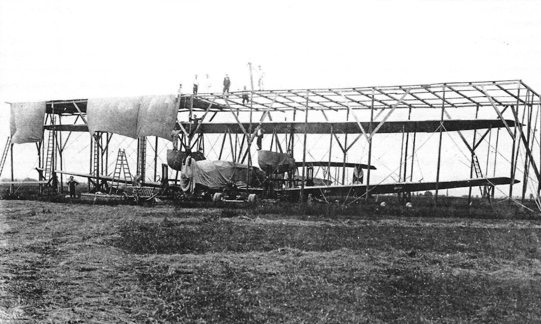
Temporary shelter being erected over the VGO.I/R.M.L.1 while under repair at Konigsberg. (Peter M. Grosz collection/STDB)
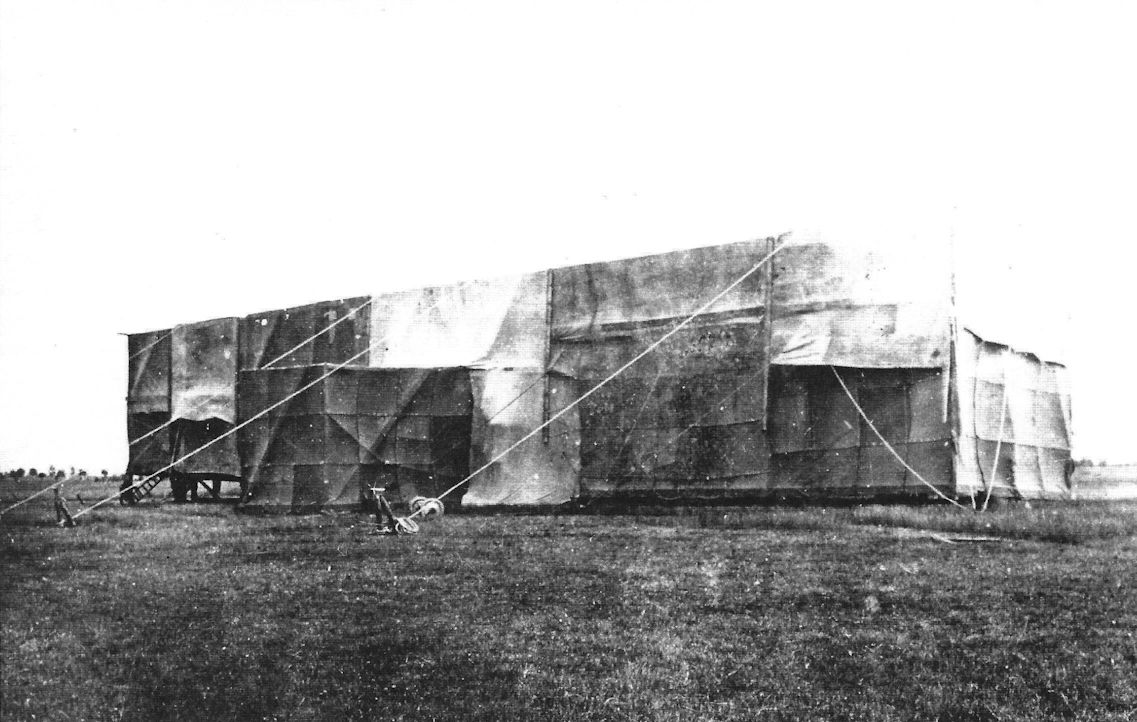
VGO.I/R.M.L.1 under repair in the temporary shelter at Konigsberg. (Peter M. Grosz collection/STDB)
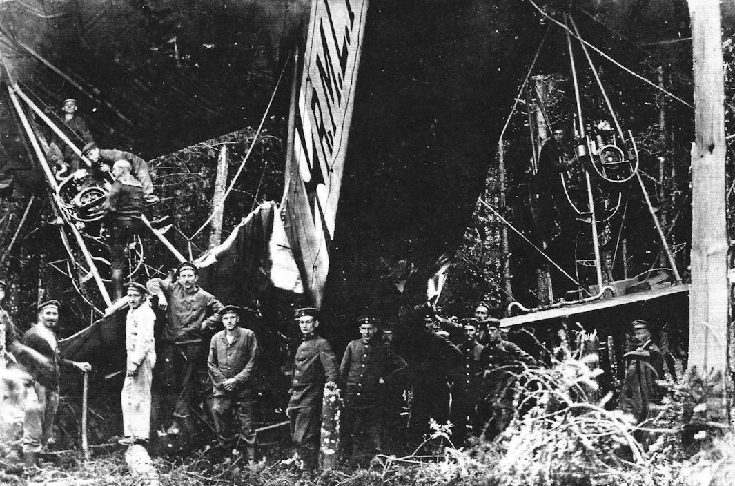
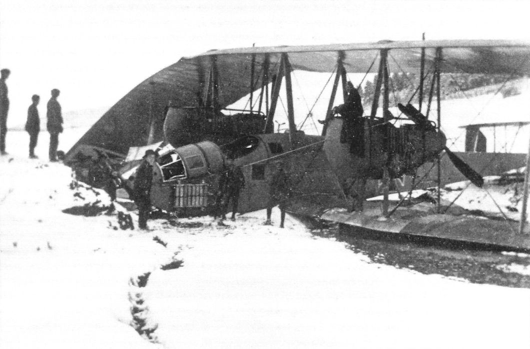
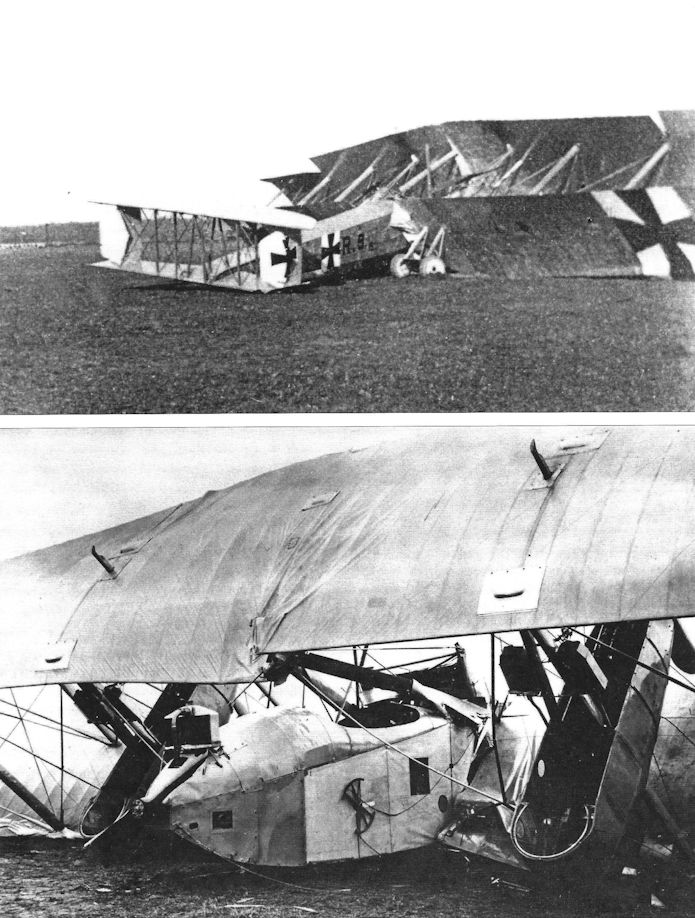
The land-based Riesenflugzeug (Giant Aeroplane) was evaluated as a possible addition to the naval airship for bombing and long-range scouting purposes. However, experience with RML1 (Reichs Navy Landplane 1) was plagued with difficulties. Engine troubles and structural failures of undercarriage assemblies were eventually overcome and the aircraft participated in some bombing operations on the Eastern Front, until, on a fully loaded night take-off late in August 1916, a double engine failure resulted in this crash into a Russian forest.
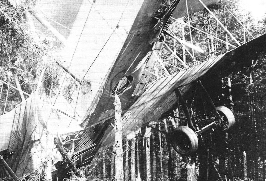
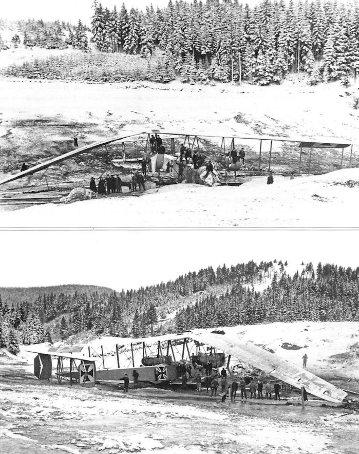
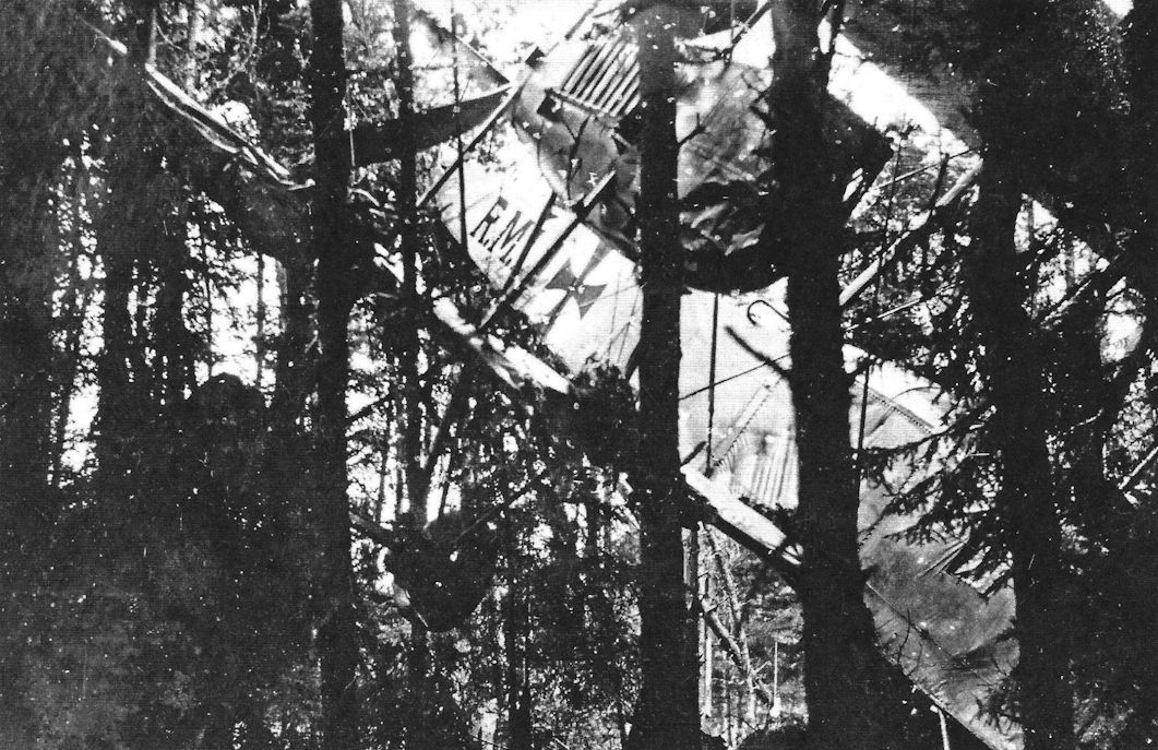
The crash of the R.M.L.1 into a pine forest. The R.M.L.1 had just taken off at night with a full load of fuel and bombs when, at 50 meters altitude, two engines "exploded". The pilots Kuring and Mann guided the plane into the pine forest where it sheared off 69 trees, cushioning the crash and preventing fire. (Peter M. Grosz collection/STDB)
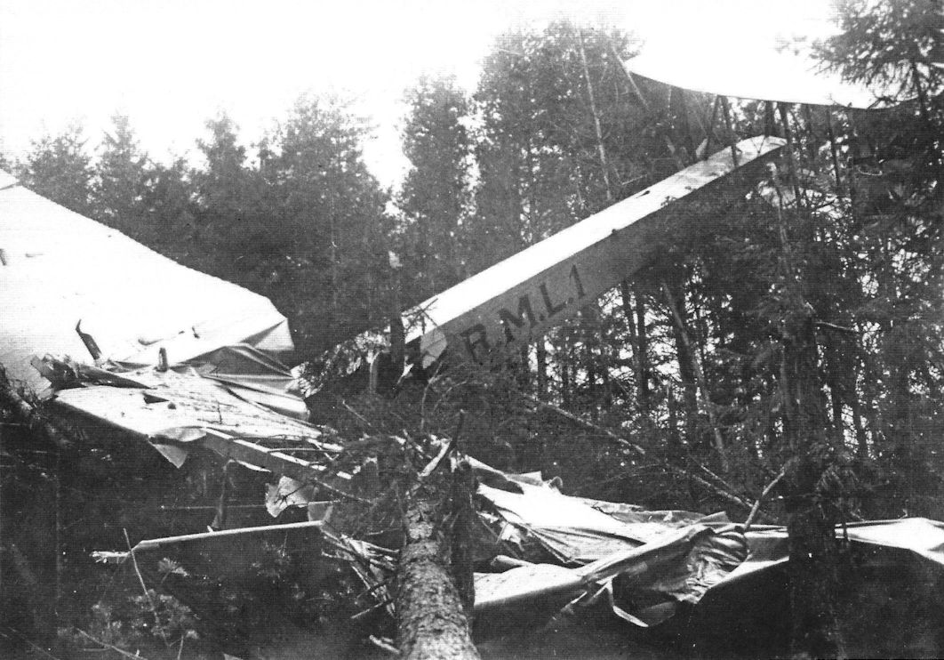
The crash of the R.M.L.1 into a pine forest. The fuselage was salvaged and sent back to Staaken where it was again rebuilt, with new wings and engines. The three unreliable HS engines were replaced with five new 245 hp Maybach Mb.IVa engines, one in the nose and two in each nacelle. (Peter M. Grosz collection/STDB)
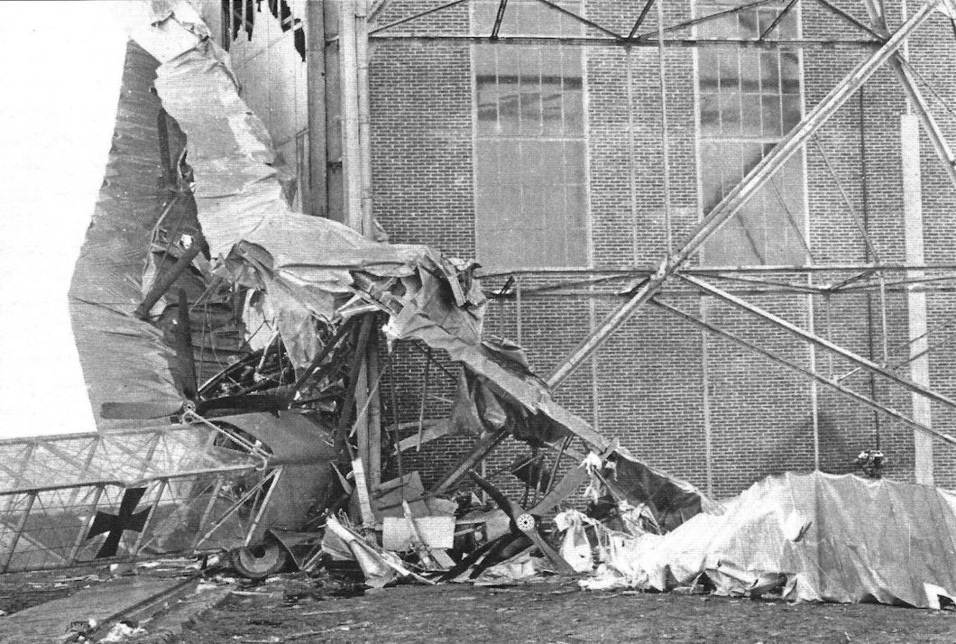
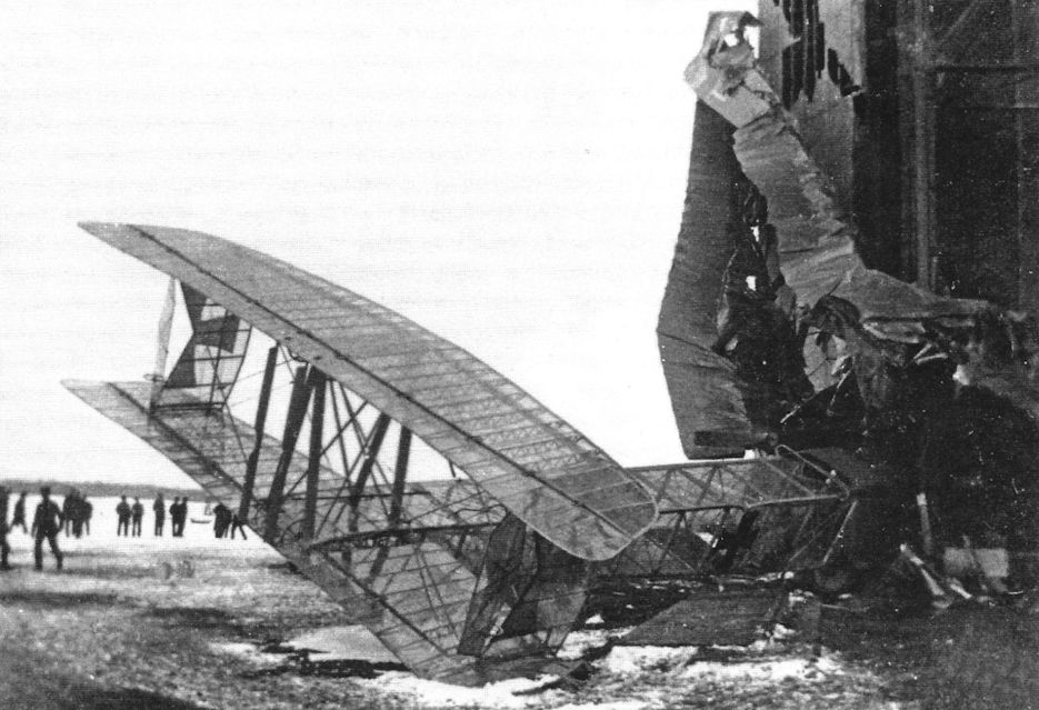
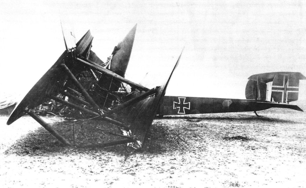
View of the final crash of the final version of the VGO I at Staaken on March 10, 1917. This was the maiden flight of the final rebuild of the aircraft. The take-off went smoothly but as the aircraft was circling the field, an explosion was heard from the left nacelle and the left propeller stopped. The pilots corrected with hard right rudder and the VGO I responded by flying in a straight line to enable it to land parallel to the airship sheds. While familiarizing himself with the controls three days earlier, Kuring, the usual second pilot, had discovered and reported that the rudder controls were networking normally. In a hard-over position the rudder pedals jammed and could not be returned to the neutral position for landing. This problem had not been repaired and the crew's pre-flight inspection had not been thorough enough to rediscover it. As Vollmoller reduced power to land, the rudder remained jammed in the hard-right position and the plane started to turn right. Kuring immediately unfastened his safety belt and crept under the instrument panel to pull the rudder pedals over from their jammed position. He was not able to do this in time and the VGO I smashed head-on into the door of the airship shed. First pilot Hans Vollmoller was killed instantly and acting second pilot Gustav Klein died after a few hours. Kuring was thrown out by the impact and suffered severe head injuries. However, eventually he was able to rejoin his unit, Marine Jasta 2, and enjoyed a long aeronautical career. However, the VGO I was a total loss and was not rebuilt. When the VGO I was rebuilt for the final time, the new fuselage and tail were covered in transparent Cellon in an early attempt to make the airplane partly invisible and this is seen in the crash photos on these pages. A top secret report showing with pictures that Cellon covering greatly reduced visibility of aircraft in the air but the fragility and water absorption of Cellon covering make it unusable in operational conditions. The Unsichtbare Flugzeug (Low Visibility Aircraft) program for giant bombers was discontinued after tests. The Linke-Hofmann R.I 8/15 was also tested with extensive Cellon covering as part of this program. (Peter M. Grosz collection/STDB)
View of the final crash of the final version of the VGO I at Staaken on March 10, 1917. This was the maiden flight of the final rebuild of the aircraft. The take-off went smoothly but as the aircraft was circling the field, an explosion was heard from the left nacelle and the left propeller stopped. The pilots corrected with hard right rudder and the VGO I responded by flying in a straight line to enable it to land parallel to the airship sheds. While familiarizing himself with the controls three days earlier, Kuring, the usual second pilot, had discovered and reported that the rudder controls were networking normally. In a hard-over position the rudder pedals jammed and could not be returned to the neutral position for landing. This problem had not been repaired and the crew's pre-flight inspection had not been thorough enough to rediscover it. As Vollmoller reduced power to land, the rudder remained jammed in the hard-right position and the plane started to turn right. Kuring immediately unfastened his safety belt and crept under the instrument panel to pull the rudder pedals over from their jammed position. He was not able to do this in time and the VGO I smashed head-on into the door of the airship shed. First pilot Hans Vollmoller was killed instantly and acting second pilot Gustav Klein died after a few hours. Kuring was thrown out by the impact and suffered severe head injuries. However, eventually he was able to rejoin his unit, Marine Jasta 2, and enjoyed a long aeronautical career. However, the VGO I was a total loss and was not rebuilt. When the VGO I was rebuilt for the final time, the new fuselage and tail were covered in transparent Cellon in an early attempt to make the airplane partly invisible and this is seen in the crash photos on these pages. A top secret report showing with pictures that Cellon covering greatly reduced visibility of aircraft in the air but the fragility and water absorption of Cellon covering make it unusable in operational conditions. The Unsichtbare Flugzeug (Low Visibility Aircraft) program for giant bombers was discontinued after tests. The Linke-Hofmann R.I 8/15 was also tested with extensive Cellon covering as part of this program. (Peter M. Grosz collection/STDB)
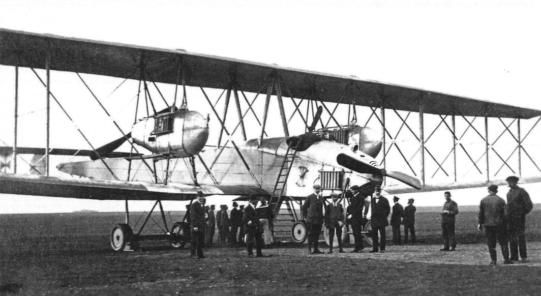
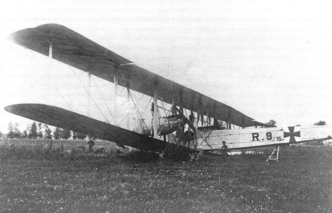
The VGO.II (R.9/15) probably taken at Dobertiz prior to its service on the Eastern Front. (Peter M. Grosz collection/ STDB)
The VGO.II (R.9/15) probably taken at Dobertiz prior to its service on the Eastern Front.. (Peter M. Grosz collection/STDB)
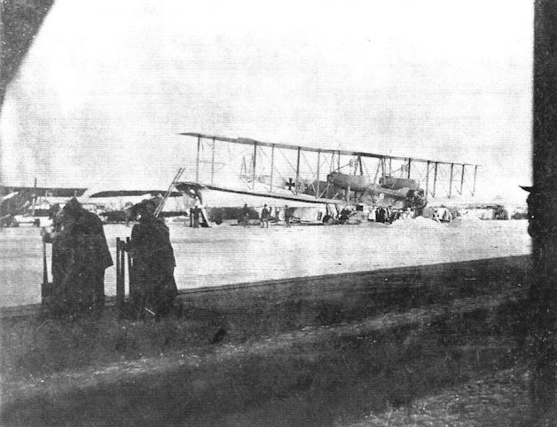
The VGO.II (R.9/15) in service in the snow. (Peter M. Grosz collection/STDB)
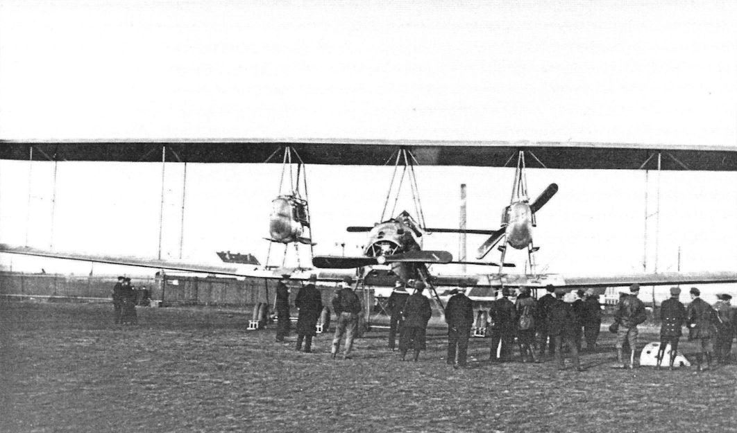
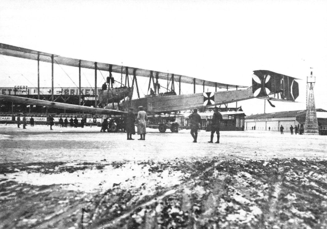
The VGO.II being admired by VIPs. (Peter M. Grosz collection/STDB)
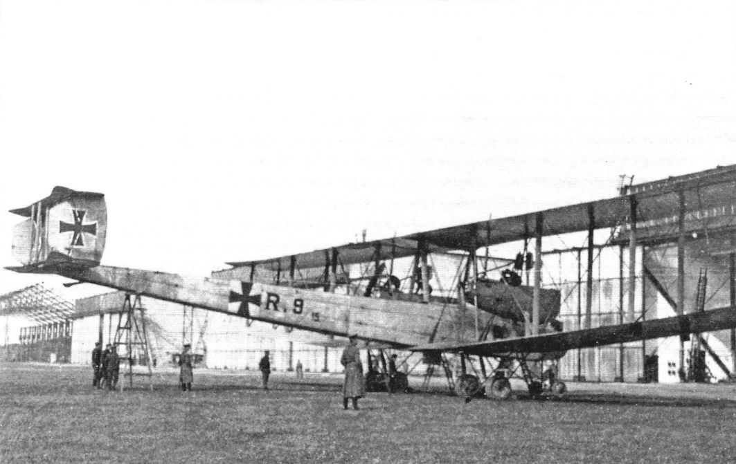
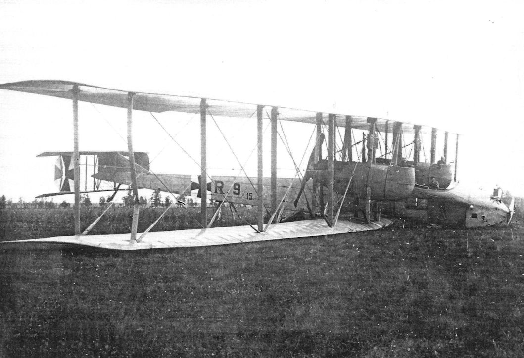
The VGO.II (R.9/15) on its airfield after modification with fixed fin. The cabin has also been modified. (Peter M. Grosz collection/STDB)
The VGO.II (R.9/15) on its airfield after modification with fixed fin. (Peter M. Grosz collection/STDB)
The VGO.II (R.9/15) in service on the Eastern Front. (Peter M. Grosz collection/STDB)
The VGO.II on the Adlershof airfield. (Peter M. Grosz collection/STDB)
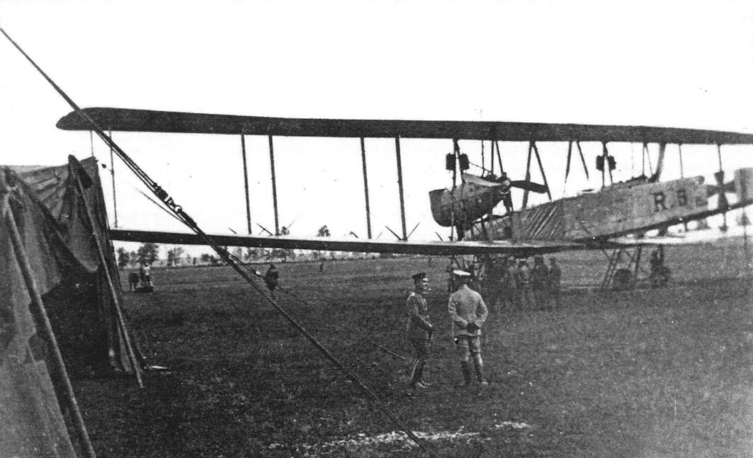
The VGO.II (R.9/15) in service on the Eastern Front. (Peter M. Grosz collection/STDB)
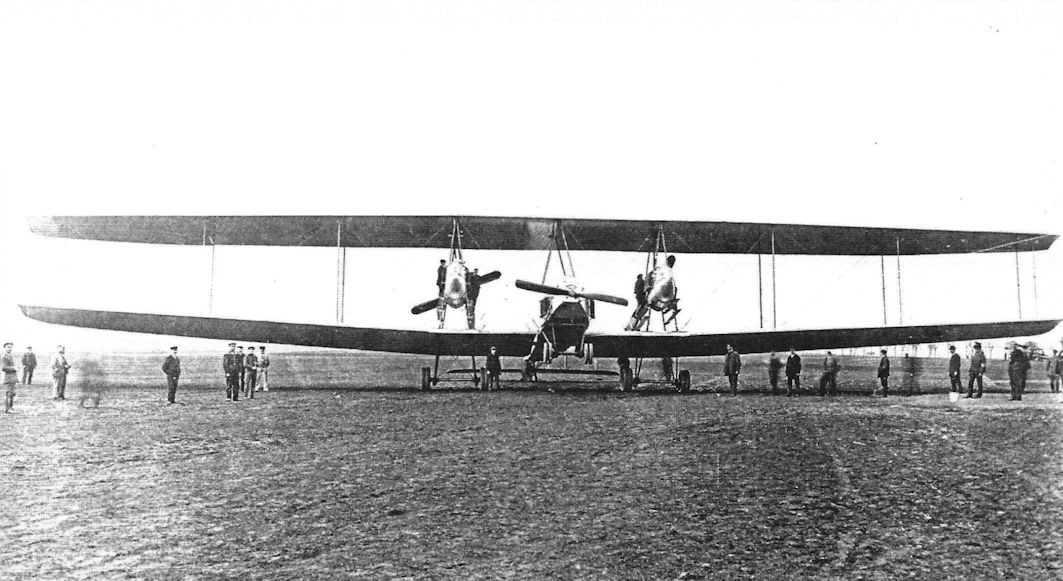
VGO.II at the factory. The fixed fin is not visible which indicates the aircraft is in its original as-built condition. (Peter M. Grosz collection/STDB)
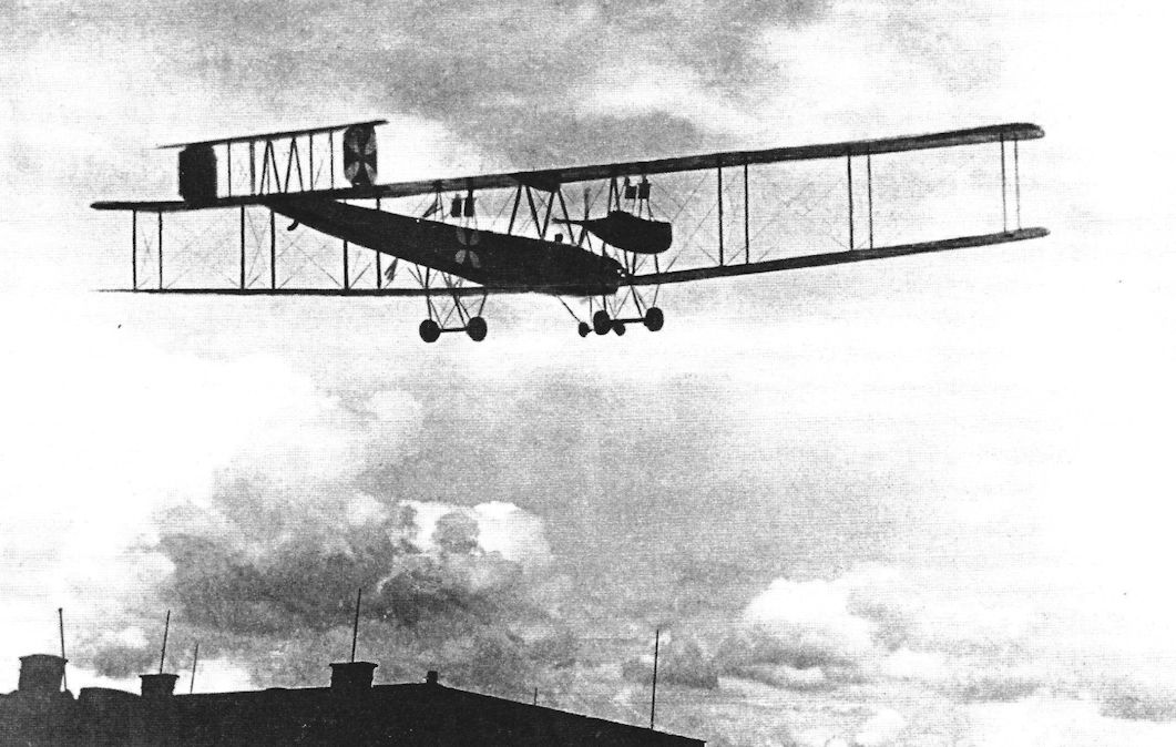
VGO.II in flight at the factory, perhaps after takeoff. (Peter M. Grosz collection/STDB)
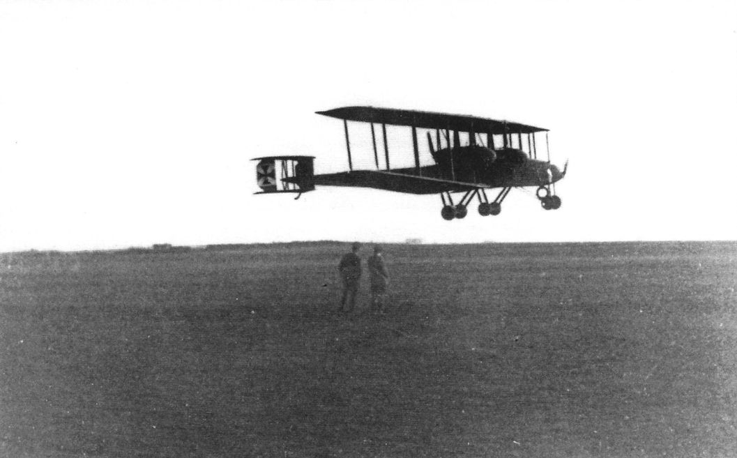
The massive VGO.II (R.9/15) in flight. (Peter M. Grosz collection/STDB)
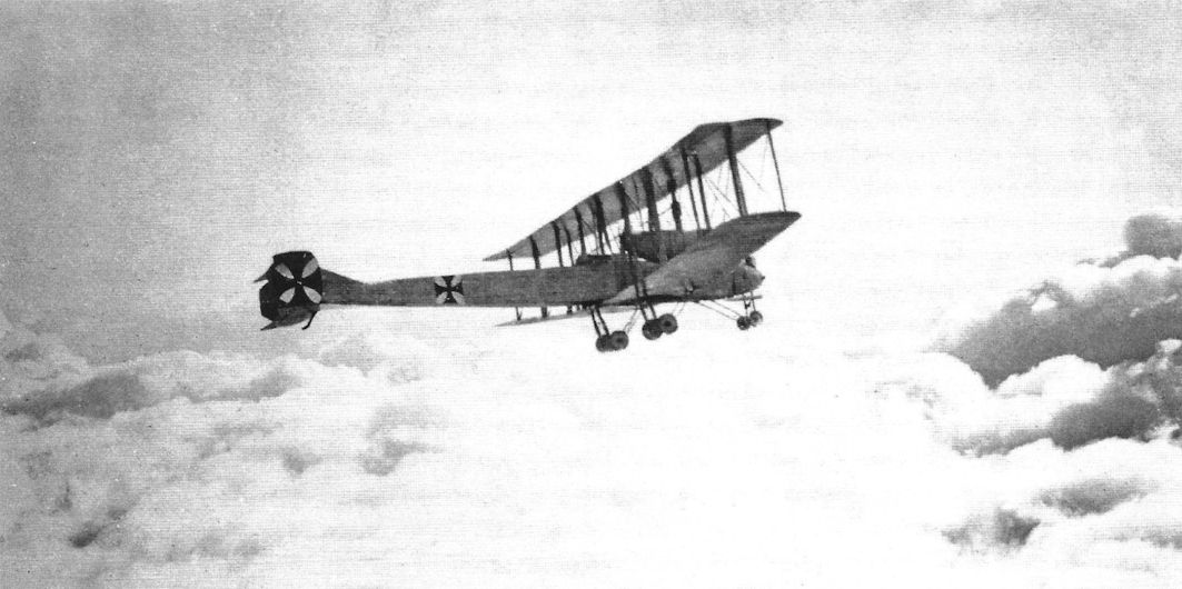
The massive VGO.II (R.9/15) in flight November 5, 1915. (Peter M.Grosz collection/STDB)
The VGO.II (R.9/15) in flight in its original configuration without fixed fin. (Peter M. Grosz collection/STDB)
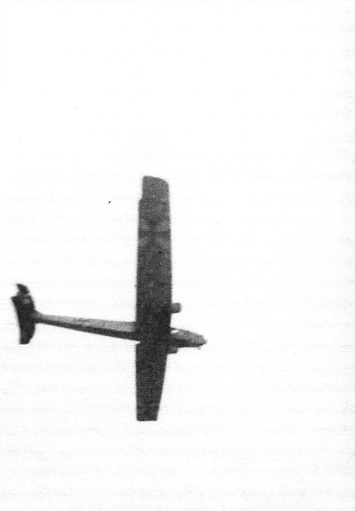
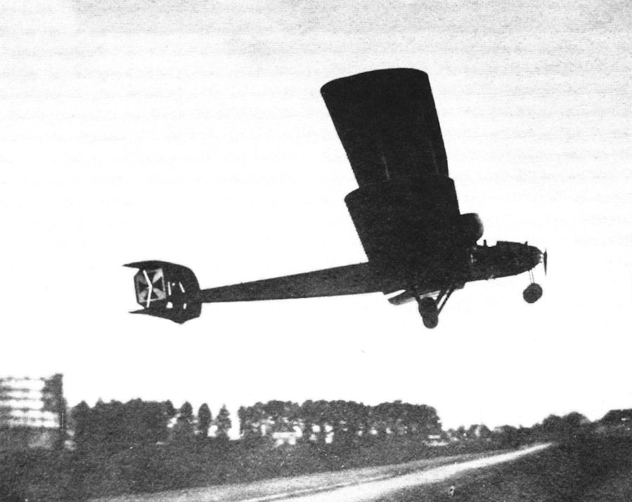
The VGO.II (R.9/15) in flight photographed from the ground. (Peter M. Grosz collection/STDB)
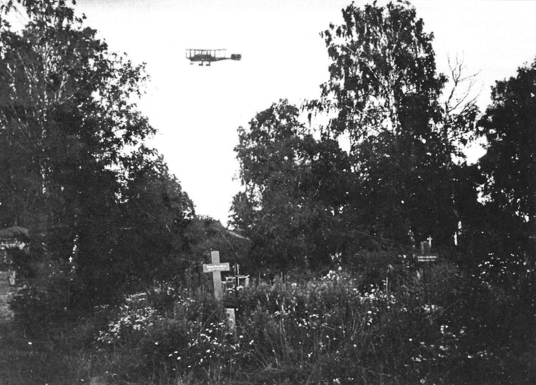
The VGO.II (R.9/15) in flight with a cemetery in the foreground. Perhaps the composition of the photograph represented the photographer’s opinion of aviators' fate. (Peter M. Grosz collection/STDB)
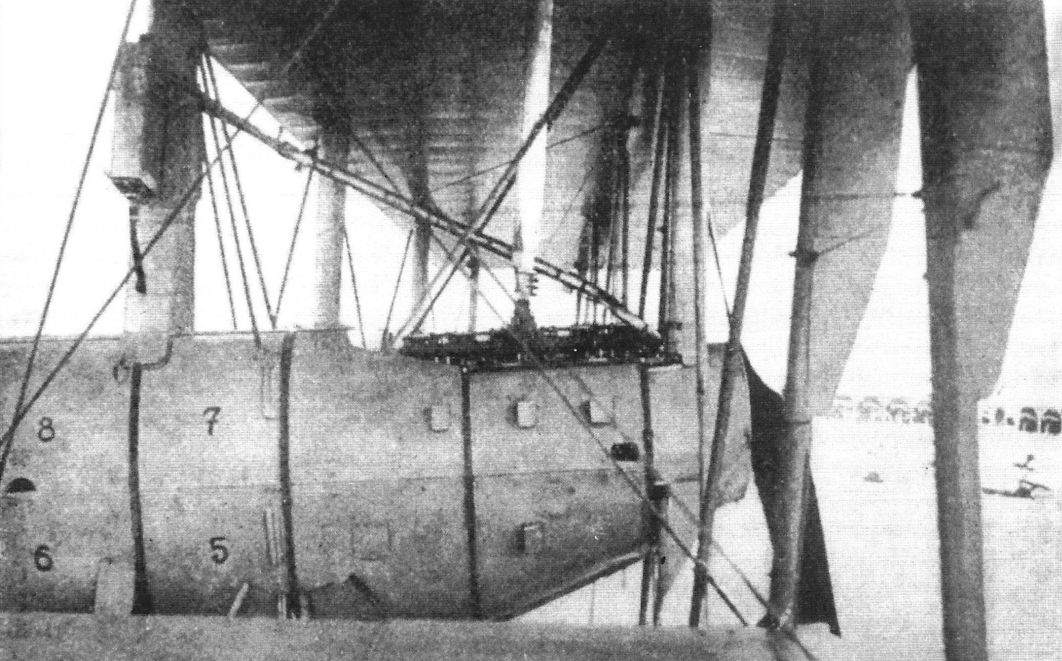
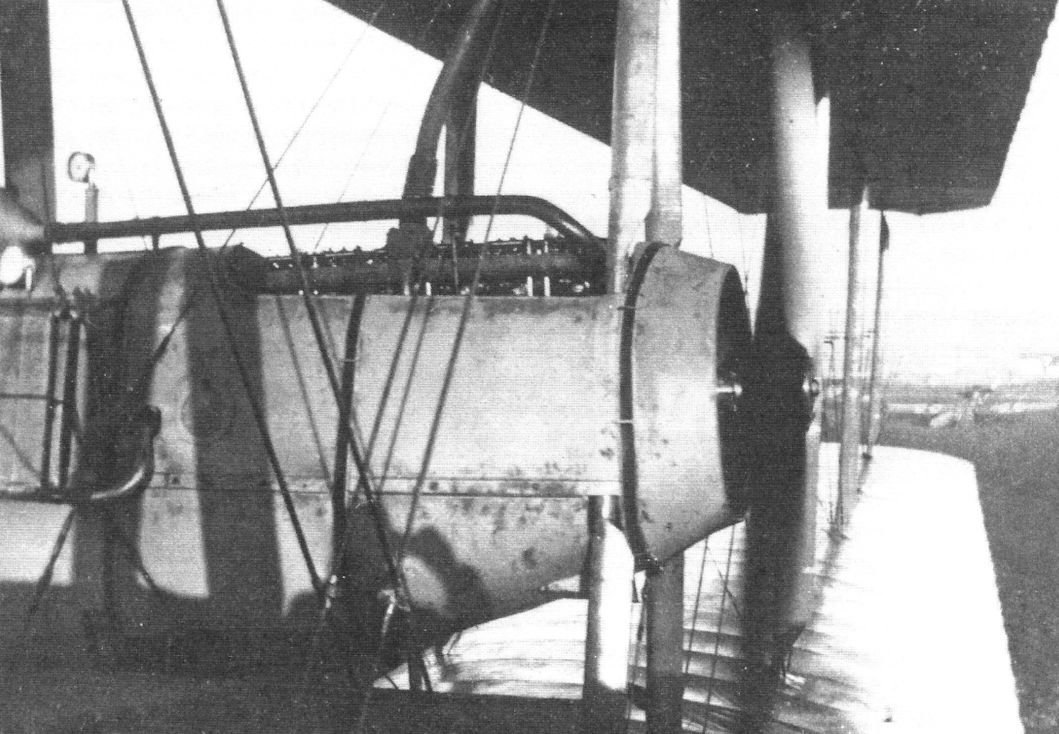
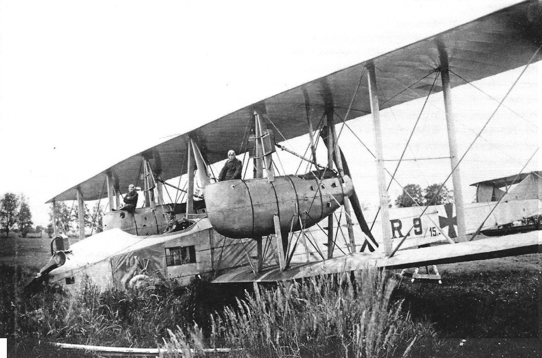
The starboard engine nacelle of the VGO.II with its Maybach HS. (Peter M. Grosz collection/STDB)
The VGO.II (R.9/15) in flight photographed from its cockpit. (Peter M. Grosz collection/STDB)
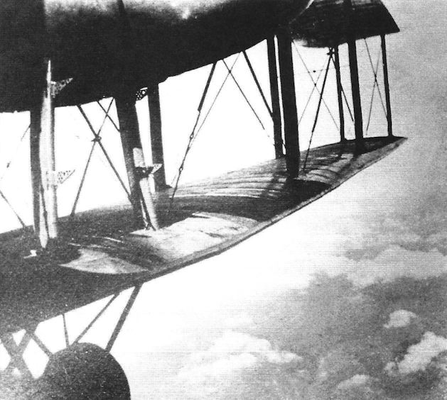
The port outer wing photographed from the cockpit in flight. (Peter M. Grosz collection/STDB)
In-flight photo taken from the left nacelle of the VGO.II. (Peter M. Grosz collection/STDB)
The VGO.II (R.9/15) photographed from its cockpit while in flight. (Peter M. Grosz collection/STDB)
The VGO.II (R.9/15) after cabin modification in flight photographed from the port nacelle. (Peter M. Grosz collection/STDB)
The VGO.II (R.9/15) under construction at the factory. The fixed fin was not present at this stage. (Peter M. Grosz collection/STDB)
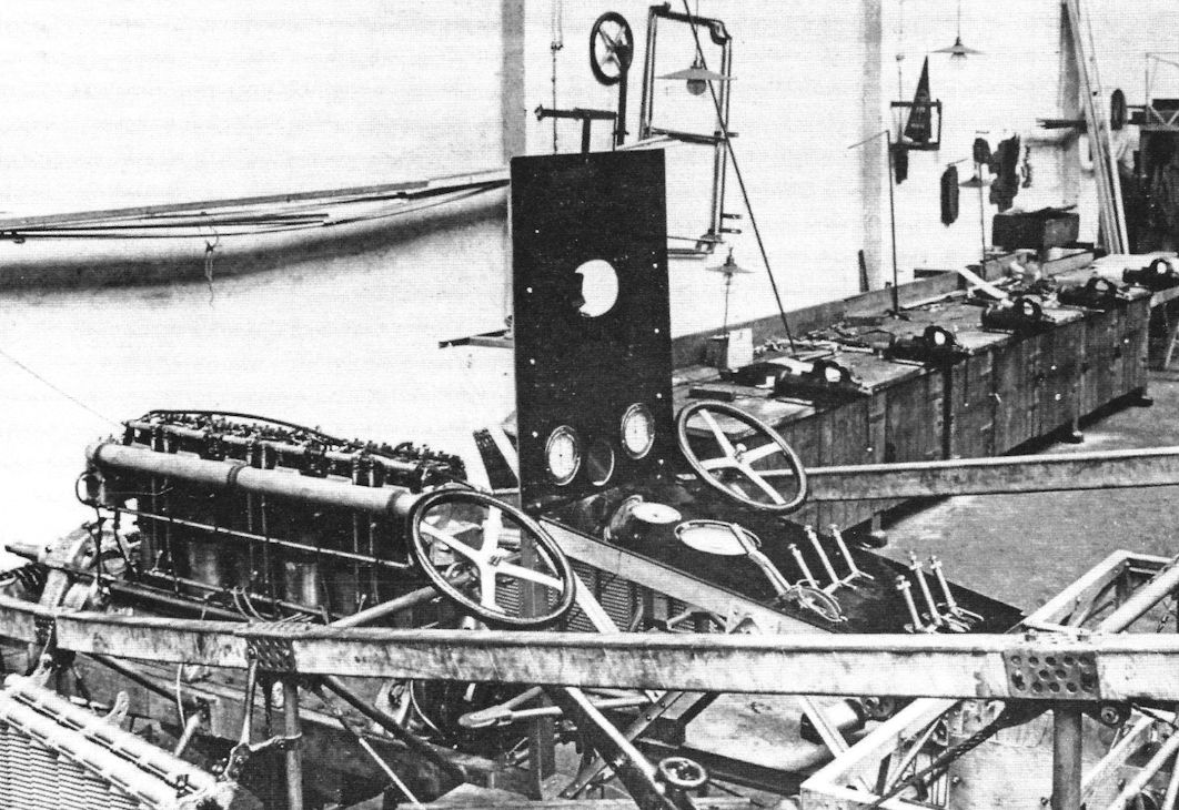
The cockpit and nose of the VGO.II being built. (Peter M. Grosz collection/STDB)
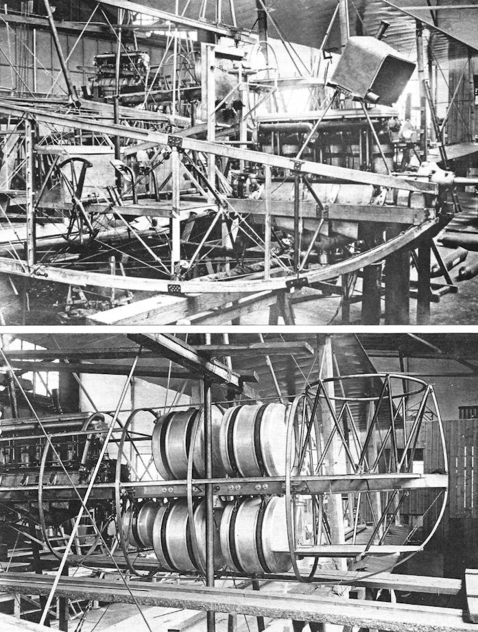
The VGO.II (R.9/15) under construction at the factory. The fixed fin was not present at this stage. (Peter M. Grosz collection/STDB)
The VGO.II undergoing maintenance after an accident involving landing gear failure.
The VGO.II (R.9/15) after a landing accident at Paulsgnade in late 1916. Fuel exhaustion due to a strong headwind returning from a bombing mission forced the plane down at a fighter field and it rolled into a ditch at the end of the runway. (Peter M. Grosz collection/STDB)
The VGO.II (R.9/15) after a landing accident at Paulsgnade near Mitau in late 1916. Fuel exhaustion due to a strong headwind returning from a bombing mission forced the plane down at a fighter field and it rolled into a ditch at the end of the runway. (Peter M. Grosz collection/STDB)
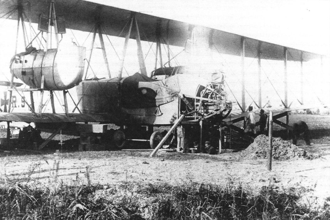
VGO.II under repair at Paulsgnade after its accident. Repairs took only a few days. (Peter M. Grosz collection/STDB)
Assigned the military serial number R.9/15, here is the VGO.II after its last landing in the summer of 1917. It was assigned as a trainer at the Rea in Doberitz on January 1, 1917. The records do not indicate any fatalities and the photo shows the aircraft did not catch fire when it crashed, so there were no known casualties. Note the raised tail surfaces. (Peter M. Grosz collection/STDB)
Staaken R.V
The Staaken R.V utilized the same basic airframe as the R.IV and earlier VGO predecessors, although its fuselage was shortened behind the wings, but its engine arrangement distinguished it from them. The R.V used five Maybach Mb.IV engines of 245 hp, making it the most powerful R-plane yet built. One engine replaced the coupled engines in the nose of the R.IV, and coupled Maybachs replaced the slightly less powerful coupled Benz engines. However, unlike previous aircraft in the VGO/Staaken series, the nacelle engines were mounted as tractors, not pushers. Thanks to that and the gunners position installed at the rear, this gave the R.V a distinctive appearance.
The more powerful engines created greater stresses in the clutches and gearboxes that reduced reliability, and these problems took some time to solve. This delayed Army acceptance until September 29, 1917, although the R.V was completed in 1916.
The engine nacelles were semi-monocoque, with plywood skin over wood frames. The result was good strength and streamlining at the cost of more labor required to construct; this precluded its use on subsequent Staaken aircraft. However, the strength greatly reduced vibration. The bottoms of the nacelles were left somewhat open to vent oil and fuel leaks. Another feature was installation of flexible gun positions with fields of fire to the rear. Together with the dorsal and ventral machine guns this gave the R.V a formidable rearward-firing armament.
To provide defense to the front, a 'swallow's nest' nacelle was added to the center section of the upper wing leading edge. This small nacelle housed the gravity tank and a gunner and flexible machine gun with all-around field of fire.
Interestingly, the R.V had a pneumatic-tube message system with six stations for sending and receiving. This worked but the simpler electric telegraph was a better solution.
Apparently the R.V was the last R-plane built at VGO. Dipl.-Ing. Lt. Otto Reichardt was transferred to Gotha to command the R.V and its large, 11-man crew. R.V was accepted at Staaken and joined Riesenflugzeug-Abteilung 501(Rfa 501) at Ghent on 23 December 1917. Its first bombing mission was January 25, 1918 against the Calais and Dunkirk. According to the Suntrop-Chronik, Koln, the R.V completed 18 combat missions bombing targets such as London, Calais, Dunkirk, Ostende, Ypres, Abbeville, St.Omer, Dieppe, Rouen, and Gravelines. In all 46 flights during the aircraft's service, "Thirteen" was lucky for its crew.
On October 18 the R.V was ordered to Dusseldorf - Lohausen. When fog was encountered during the flight, Lt. Pickerott, the new aircraft commander, ordered the pilots to make an emergency landing, much against their better judgment. The R.V was nearly destroyed in the attempt, although only Pickerott was injured with a broken ankle.
Vzfw. Heinrich Schmitz writes in his memories the aircraft was disassembled and returned to Staaken for repair, but the end of the war stopped it.
Staaken Specifications
Type V.G.O. Ill R.IV R.V
Engines 6x160 Hp Mercedes D.III 2x160 Hp Mercedes D.III 4x220 Hp Benz Bz.IV 5x245 Hp Maybach Mb.IVa
Span 42.2 m (138'5 1/2") 42.2 m (138'5 1/2") 42.2 m (138' 5 1/2")
Chord (inner) - 4.6 m (15' 1") 4.6 m (138' 5 1/2")
Chord (outer) - 3.6 m (11' 10") 3.6 m (11' 10")
Length 24.5 m (80' 4 1/2") 23.2 m (76' 1") 23 m (75' 5 1/2")
Height 6.8 m (22' 3 1/2") 6.8 m (22' 3 1/2") 6.8 m (22'3 1/2")
Tail span - 9 m (29' 6") -
Wing Area 332 m2 (3,572 ft2) 332 m2 (3,572 ft2) 332 m2 (3,572 ft2)
Wt. Empty 8,600 kg (18,963 lb.) 8,772 kg (19,342 lb.) 9,450 kg (20,837 lb.)
Wt. Fuel - 2,140 kg (4,719 lb.) -
Wt. Payload - 2,123 kg (4,681 lb.) 3,560 kg (7,850 lb.)
Wt. Loaded 11,600 kg (25,578 lb.) 13,035 kg (28,742 lb.) 13,010 kg (28,687 lb.)
Max Speed 120 km/h (75 mph) 125 km/h (77.5 mph) 135 km/h (83.9 mph)
Climb 1,000 m 16 minutes 10 minutes 10 minutes
Climb 2,000 m 29 minutes 35 minutes 22 minutes
Climb 3,000 m 56 minutes 89 minutes 34 minutes
Ceiling 3,000 m 3,700 m 4,500 m
Duration 6 hours 6-7 hours -

Staaken R.V R.13/15 in early camouflage.

Staaken R.V R.13/15 in late camouflage.

The R.V crew pre-flighting the aircraft for the next night combat mission. On the wing, near the cabin is standing 1st pilot Vizefeldwebel Heinrich Schmitz. May 1918 Schweldewindeke airfield. Note the 'Swallow nest' gun ring mounted at upper wing fuel tank. This mount is a German copy of British Scarf ring. The R.V is fully camouflaged for night operations. According to intelligence reports the day-time camouflage was over-painted by a matt blue lacquer mixture, with dark Prussian blue and ultramarine pigment. (Peter M. Grosz collection/STDB)

Close-up of R.13 showing details.

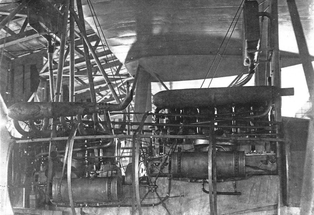
Photo taken shortly after the propeller was changed from two-bladed to four-bladed Garuda.The small spinner is not yet mounted. The small oil radiator is visible at the bottom of the nacelle. Here was cooling oil for both engines and the gear box which drove the Garuda aircrew. Two Hans Window radiators are mounted on the nacelle struts. The front engine is mounted lower and the rear is higher. (Peter M. Grosz collection/STDB)

Close-up of the R.V showing the 'swallow's nest' gun nacelle in the upper wing. (Peter M. Grosz collection/STDB)

R.13 warming up all engines, before take-off. The whole aircraft is painted with hexagonal night camouflage. Colors were very probably: green, dark ruby, Prussian blue and yellow, over-painted by matt dark blue lacquer. (Peter M. Grosz collection/STDB)

Staaken R.V 13/15. The engines are being tested in preparation for a night mission from Scheldewindeke in 1918. At this time all propellers had two blades; later the nacelle propellers had four blades. (Peter M. Grosz collection/STDB)

The R.13 with all propellers fitted with four blades. (Peter M. Grosz collection/STDB)

The R.13 during preparation for its next night combat mission. (Peter M. Grosz collection/ STDB)

The R.13 during continued preparation for its next night combat mission. (Peter M. Grosz collection/ STDB)

The massive R.V being readied for another mission. (Peter M. Grosz collection/STDB)

Flight engineer in his gunner's position.

Crewman in the 'swallow's nest'. This had a flexible machine gun with 360° field of fire above the wing.

View taken from right nacelle showing the gunner's position at the rear of the nacelle giving the R.V great firepower to the rear. On the gun ring is a Parabellum 14/17 with enlarged drum magazine. The side ladder mounted at the nacelle side is clearly seen. (Peter M. Grosz collection/STDB)

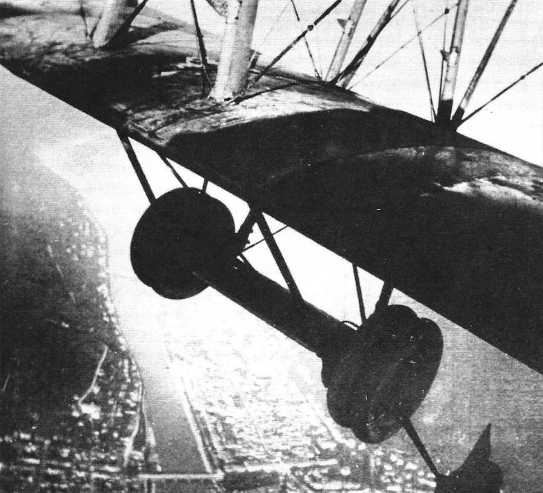
In-flight photos taken from the starboard engine nacelle. (Peter M. Grosz collection/STDB)

Another view taken from the right nacelle showing the dorsal gun position. Guns are not mounted, suggesting the flight is not a combat mission. (Peter M. Grosz collection/STDB)

In-flight view taken from the right nacelle gunner position showing the characteristic Staaken tail unit on the R.V. The third rudder was never added to this (Staaken R.13) aircraft. (Peter M. Grosz collection/STDB)


In-flight photos taken from the starboard engine nacelle. (Peter M. Grosz collection/STDB)

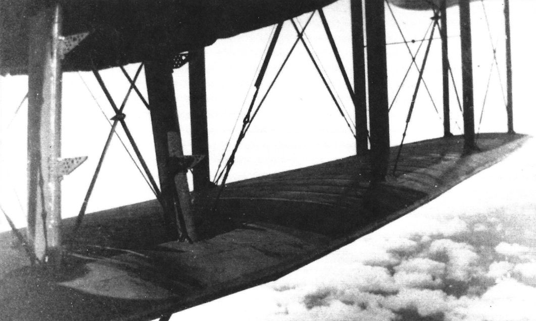
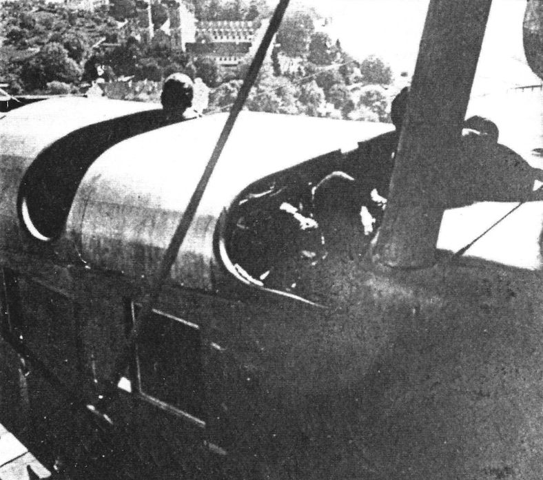
THE ZEPPELIN GIANT AEROPLANE. - Looking down from the machine gunner's nest at the two pilots, the observer, and the commander.
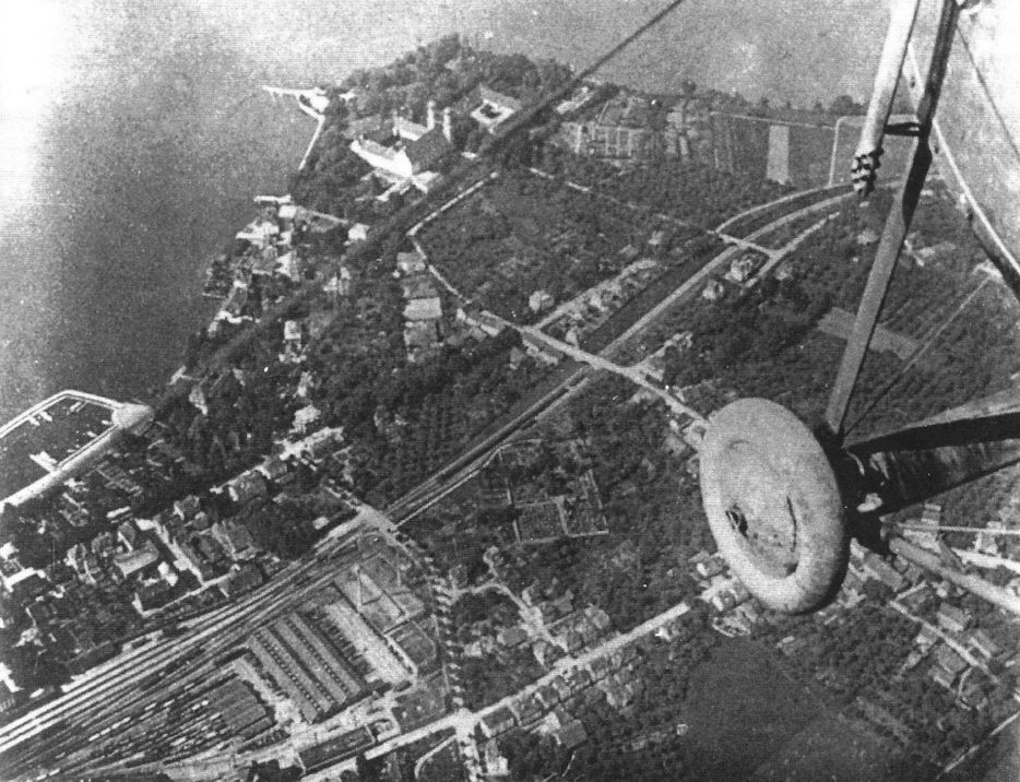
View taken from the 'swallow's nest' of the pilots cockpit and front engine room. Ghent, Belgium is seen in the background. In the cabin are pilots Schmitz and Roeder and behind them is Lt. Pickerott, the aircraft commander, and Reichardt. (Peter M. Grosz collection/ STDB)
View taken from the 'swallow's nest' of the pilots cockpit and front engine room. Ghent, Belgium is seen in the background. In the cabin are pilots Schmitz and Roeder and behind them is Lt. Pickerott, the aircraft commander, and Reichardt. (Peter M. Grosz collection/ STDB)


View aft from the "swallows nest" on the R.V.

The Staaken R.V and its eleven crew photographed prior to its crash in October 1918. The aircraft commander Lt. Ernst Pickerott, first pilot Vizefeldwebel Heinrich Schmitz, second pilot Waldemar Roeder. Note the "Kathchen" Paulus Systeme parachute belts worn by some aviators. At this time, the R.V had eleven members: aircraft commander, two pilots, one observer officer, one flight engineer responsible for gasoline distribution, one radio operator, two mechanics, and three gunners. The crew strength varied from eight to 14 members according to the mission type. (Peter M. Grosz collection/STDB)

Right nacelle photographed during maintenance. The bottom panels are removed and the inner wood frames of the nacelle structure are clearly seen. The brush-painted matt dark blue colored lacquer application is visible. (Peter M. Grosz collection/STDB)

Nacelle during aircraft maintenance. The nacelle construction can be seen under the dismounted bottom panels. At the lower wing root is a four-bladed wind propeller powering the fuel pump. (Peter M. Grosz collection/STDB)

R.V cockpit under construction.

In-flight view of the inside of the engine nacelle. (Peter M. Grosz collection/STDB)

Antenna wheel located at the radio operator's position. (Peter M. Grosz collection/STDB)
The wreck of Zeppelin Staaken R.V (R.13/15) that crashed near Heistern, 3 October 1918 (18 October in other sources). After flying in heavy rain and fog all engines started to run badly and the new aircraft commander ordered the pilots to make an emergency landing. This was against their better judgment and the results showed why; the R.V was basically destroyed in the landing. Fourteen crew members and passengers were fortunate; only one person (Lt. Pickerott, the aircraft commander) was injured. Note the Balken cross painted at rudder. (Peter M. Grosz collection/ STDB)

Another view of the crashed R.V. The fuselage cross shows were the old cross was scraped off and the new cross was painted on. Note the partially opened, nacelle gunner's parachute (probably a Kathchen Paulus Systeme) laying along the right nacelle. From 1917 the Rfa unit started to mount and test parachutes from two Systeme. First: Kathchen Paulus. The life saving parachute (Rettungsfallschirm) type"K. P." primary was used at early LZ, SL, and PL type Airships and observation balloons. Second: The Heinecke parachute system, designed for fighters and two-seater aircraft. Finally after tests the system Heinecke was chosen for Riesenflugze. But probably from an insufficient supply of parachutes, both types were used. (Peter M. Grosz collection/STDB)

View of the upper wing of the crashed R.V (R.13/15) bomber. Note the night camouflage (dark blue color) overpainted the lozenge pattern and the scraped crosses. The lozenges on the wing undersides are brighter than on the fuselage and upper side so must be not darkened by dark bluish lacquer. (Peter M. Grosz collection/STDB)


Pneumatic tube system in Staaken R-planes.

Diagram of the R.V engine nacelles.

Staaken R.V R.13/15 early & late camouflage.
VGO.III
Construction of the VGO.III began in October 1915 at VGO. By now the bitter experience with the Maybach HS engines had motivated the design team to find more reliable alternatives to power the aircraft. Their solution was the proven reliable Mercedes D.III; however, that engine produced only 160 hp, so the team used six of them. This also raised the aircraft's total power to 960 hp from the 720 hp of the earlier aircraft.
The designers chose a creative way to mount the engines. To enable the new aircraft to retain the basic design of its predecessors, the six engines were mounted in three pairs, with two engines coupled together to drive each of the three propellers. In the nose, two engines were mounted side by side, and their crankshafts were coupled to a common gearbox via clutch assemblies and short extension shafts. The clutch assemblies enabled a failed engine to be decoupled from the propeller gearbox, allowing the other engine to continue powering the propeller. One of the engineering challenges with the engine coupling design was vibration; at some engine revolutions standing waves could be seen in the extension shafts.
In the wing-mounted engine nacelles, the leading engine was mounted low and the aft engine was mounted higher, enabling the extension shaft from the leading engine to pass beneath the aft engine. Again, both extension shafts drove the propeller via clutches and a gearbox. As with the nose-mounted engines, individual engines could be decoupled from the gearbox and started or stopped independently. The engines were tended by flight mechanics who also manned flexible machine guns mounted at the front of the nacelle.
The rest of the VGO.III aircraft was nearly identical to the VGO.II, including the airframe and flexible guns mounted in dorsal and ventral positions in the fuselage, although the pilots' cockpit was moved farther aft and fin area was slightly increased. A new feature was addition of a long-range gravity tank mounted at the junction of the center-section struts. Another new feature evaluated in flight testing was separate aileron balances mounted between the wings in an attempt to reduce aileron control forces. These were later removed and not tried again by Staaken. Addition of 2 cm Becker cannon to the defensive armament was also considered but not actually tried.
The crew was seven men, including a radioman (known as a wireless operator at the time) who operated a Siemens-Schuckert transmitter and Telefunken receiver which were powered by an AEG generator driven by a two-cylinder Bosch gas engine. Attempts to eliminate the necessity for the Bosch engine by driving the generator directly by the engines or a small propeller driven by the slip-stream did not succeed.
The date of the maiden flight is not known, but the VGO.III flew from Gotha to Friedrichshafen on June 13, 1916 for tests on the propeller reduction gearing. VGO.III was accepted by Idflieg on August 28, 1916 and delivered to Rfa 500 on the Eastern Front on September 8. There it completed seven bombing missions against strategic targets like railway installations and troop bivouacs near Riga. One of those missions was on September 22; the mission duration was 3 hours and 10 minutes, the altitude reached was 3,000 m, and the useful load was 3,310 kg.
An unfortunate milestone by the VGO.III was the first fatal accident in an R-plane, which occurred on January 24, 1917. VGO.III was returning from a training mission to land at Alt-Auz when it was caught in a downdraft; touching down prematurely, VGO.III hit a snow-covered obstacle after about 10 m landing run. The front wheels broke off, the main under-carriage then collapsed, the fuselage broke in two, and the lower wings were torn off. Fuel lines were broken and sprayed fuel over the hot exhaust stacks in the nose. VGO.III was burned up in the resulting fire and half the crew were killed.
Staaken R.IV
Zeppelin moved their R-plane works to Staaken near Berlin in early 1916. This move was motivated by a desire to avoid potential Allied bombing raids by moving out of range of Allied aircraft. The VGO works was officially moved to Staaken from Gotha on August 1, 1916 and re-named Flugzeugwerft GmbH. An additional benefit was to release space for more production at Gotha; at the same time Staaken had more facilities for expansion.
Construction of the fourth Staaken R-plane at VGO started in February 1916 and it completed its maiden flight on August 16, 1916. By the time it was delivered to the Army the company transfer to Staaken was official; therefore the new aircraft was the first R-plane to be given a Staaken designation, the Staaken R.IV.
The Staaken R.IV, serial R.12/15, was very similar in layout to the VGO.III. The airframe remained essentially the same, as did the nose engine installation and two engines driving pusher propellers in each nacelle. The horizontal tail surfaces were moved to the top of the rear fuselage to prevent damage when landing.
The desire for more power drove the installation of the new 220 hp Benz Bz.IV engines in the engine nacelles, replacing the 160 hp Mercedes used in the VGO.III. The large, 4-bladed propellers made by Garuda rotated in opposite directions to minimize asymmetric thrust and improve flying qualities. Initially, the nacelle radiators were mounted like those in the VGO.III. However, the more powerful engines needed more cooling and the original radiators were replaced by larger ones arranged differently. Instead of mounting the radiators side by side, they were mounted on the front and rear struts and the front radiator was mounted higher than the rear to avoid obstructing air-flow to the rear radiator.
Defensive armament was improved in the R.IV. Machine-gun positions were added into the upper wings above the engine nacelles and behind the rear wing spar. These were reached by a ladder from the nacelle and offered a 360° field of fire above the wings. A platform gave the gunner a place to stand and could be folded out of the way to enable the gunner to climb up and down, and sliding panels above and below the wing surfaces reduced drag when the gun was not deployed. The armament then consisted of seven flexible guns; one above each nacelle, one in the front of each nacelle, two guns in the dorsal position, and another gun in the ventral position. This gave the gunners wide fields of fire, much of it overlapping, and was formidable for the time.
Partly due to the assignment of well-trained and experienced flight crew, the R.IV was able to be thoroughly flight-tested, modified, and maintained. Coupled with its proven airframe and more powerful, reliable engines, the result was that the R.IV was the single most successful R-plane in service. It was accepted by the Army on May 5, 1917 and served operationally longer than any other R-plane; it was the only R-plane to serve operationally on both the Eastern and Western Fronts and served until the end of the war.
On 12 June 1917 the R.IV started its delivery flight to join Rfa 500 on the Eastern Front. There it completed a number of raids in June and July. Then it was transferred to the Western Front. During the transfer, it flew from Gotha to Alt-Auz to Metz without incident. Both of these flights were made at night without being ordered to do so, a reflection of the crew's confidence in the aircraft.
On the Western Front the R.IV was assigned to Rfa 501 based at Ghent in Belgium. From there the R.IV flew bombing missions against London among numerous other targets.
Staaken Specifications
Type V.G.O.Ill R.IV R.V
Engines 6x160 Hp Mercedes D.III 2x160 Hp Mercedes D.III 4x220 Hp Benz Bz.IV 5x245 Hp Maybach Mb.IVa
Span 42.2 m (138'5 1/2") 42.2 m (138'5 1/2") 42.2 m (138' 5 1/2")
Chord (inner) - 4.6 m (15' 1") 4.6 m (138' 5 1/2")
Chord (outer) - 3.6 m (11' 10") 3.6 m (11' 10")
Length 24.5 m (80' 4 1/2") 23.2 m (76' 1") 23 m (75' 5 1/2")
Height 6.8 m (22' 3 1/2") 6.8 m (22' 3 1/2") 6.8 m (22'3 1/2")
Tail span - 9 m (29' 6") -
Wing Area 332 m2 (3,572 ft2) 332 m2 (3,572 ft2) 332 m2 (3,572 ft2)
Wt. Empty 8,600 kg (18,963 lb.) 8,772 kg (19,342 lb.) 9,450 kg (20,837 lb.)
Wt. Fuel - 2,140 kg (4,719 lb.) -
Wt. Payload - 2,123 kg (4,681 lb.) 3,560 kg (7,850 lb.)
Wt. Loaded 11,600 kg (25,578 lb.) 13,035 kg (28,742 lb.) 13,010 kg (28,687 lb.)
Max Speed 120 km/h (75 mph) 125 km/h (77.5 mph) 135 km/h (83.9 mph)
Climb 1,000 m 16 minutes 10 minutes 10 minutes
Climb 2,000 m 29 minutes 35 minutes 22 minutes
Climb 3,000 m 56 minutes 89 minutes 34 minutes
Ceiling 3,000 m 3,700 m 4,500 m
Duration 6 hours 6-7 hours -
Staaken Specifications
Type R.VII R.VIII & R.IX 8307
Engines 2x160 Hp Mercedes D.III 4x220 Hp Benz Bz.IV 8x260 Hp Mercedes D.IVa OR 8x245 Hp Maybach Mb.IVa 4x530 Hp Benz Bz.VI
Span 42.2 m (138'5 1/2") 55 m (180'5") -
Length 22.1 m (72' 6") 30 m (98'5") -
Height 6.8 m (22' 3 1/2") 8.8 m (28' 10") -
Wing Area 332 m2 (3,572 ft2) - -
Wt. Empty 8,923 kg (19,675 lb.) - -
Wt. Fuel 2,140 kg (4,719 lb.) - -
Wt. Payload 1,890 kg (4,167 lb.) - -
Wt. Loaded 12,953 kg (28,561 lb.) - -
Max Speed 130 km/h (80.8 mph) - -
Climb 1,000 m 12 minutes - -
Climb 2,000 m 25.5 minutes - -
Climb 3,000 m 50 minutes - -
Ceiling 3,850 m - -
The Staaken R.VIII, R.IX, and 8307 were unbuilt projects. The 8307 was a seaplane for the Navy.
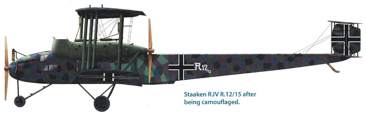
Staaken R.IV R.12/15 after being camouflaged.
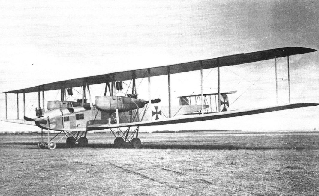
The VGO.III R.10/15 was nearly identical in appearance to the earlier Staaken aircraft but with a simplified tail with no fixed fin. However, the engines were updated to the reliable 160 hp Mercedes mounted in pairs for each propeller.
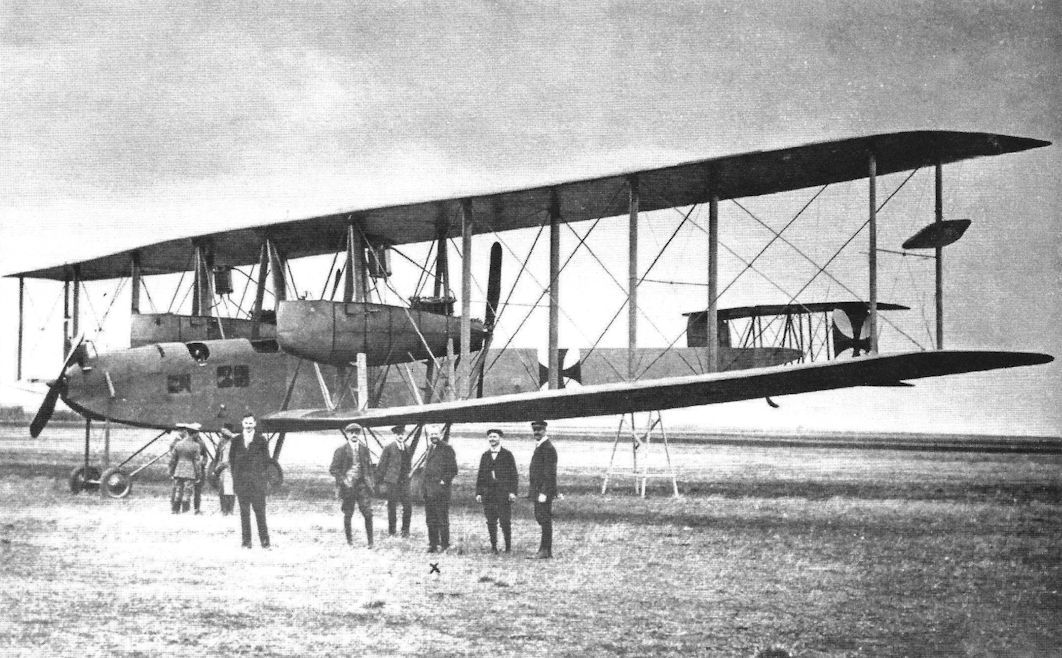
During flight testing the VGO.III was fitted with an auxiliary aileron balance on the rear outer interplane struts. These surfaces were designed to reduce aileron control forces to improve aileron response and reduce pilot fatigue. The surfaces were hinged aft of their center and connected to the ailerons. Similar methods of aileron balancing were tried by Gotha and Brandenburg seaplanes. However, the surfaces were removed from the VGO.III and not used on other Staaken aircraft. (Peter M. Grosz collection/STDB)
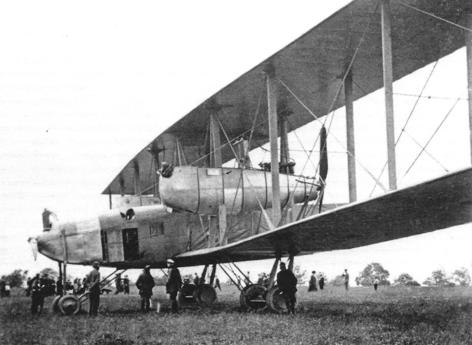
The VGO.III being admired by a group of VIPs and guests. These views show the aircraft's details and massive size. (Peter M. Grosz collection/STDB)
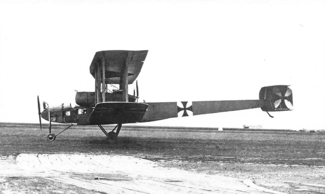
More views of the VGO.III R.10/15. It was a very large, impressive for the time. The overall configuration was conventionally similar to smaller biplanes. The aircraft's size and engine arrangement were the aspects that distinguished it from more common aircraft. (Peter M. Grosz collection/STDB)
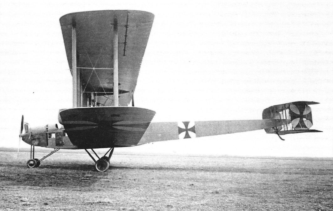
Powered by six engines, the Zeppelin-Staaken VGO III was the first of the strategic bombers' produced by this company. The aircraft saw operational service with RFa 500 on the Eastern Front in the early days of 1915; although its top speed was only 75mph (120kph) and its ceiling only 6,560ft (2,000m) it was defended by five machine guns.
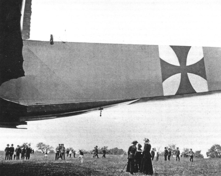
The VGO.III being admired by a group of VIPs and guests. These views show the aircraft's details and massive size. (Peter M. Grosz collection/STDB)
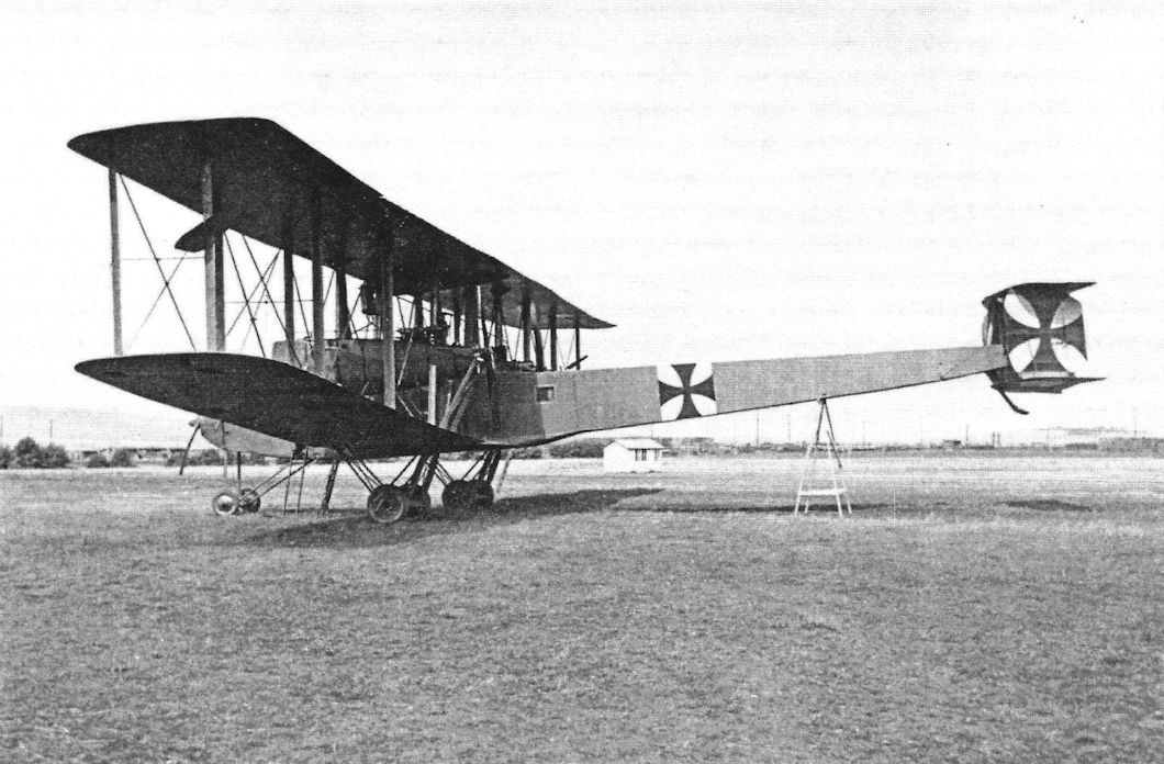
During flight testing the VGO.III was fitted with an auxiliary aileron balance on the rear outer interplane struts. These surfaces were designed to reduce aileron control forces to improve aileron response and reduce pilot fatigue. The surfaces were hinged aft of their center and connected to the ailerons. Similar methods of aileron balancing were tried by Gotha and Brandenburg seaplanes. However, the surfaces were removed from the VGO.III and not used on other Staaken aircraft. (Peter M. Grosz collection/STDB)
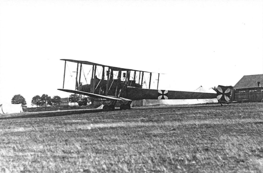
Side view of the VGO.III shows its basic configuration is essentially the same as the earlier VGO.I and VGO.II. (Peter M. Grosz collection/STDB)
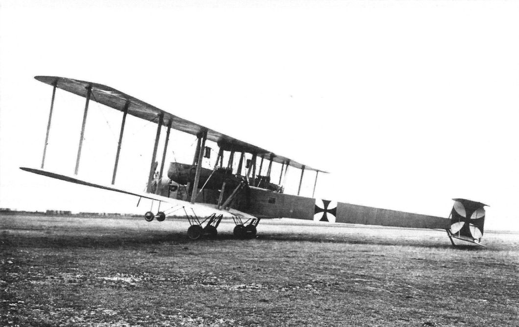
The VGO.III is here shown resting all its tailskid; the more normal attitude was for it to rest on its nose wheels with the tail high.
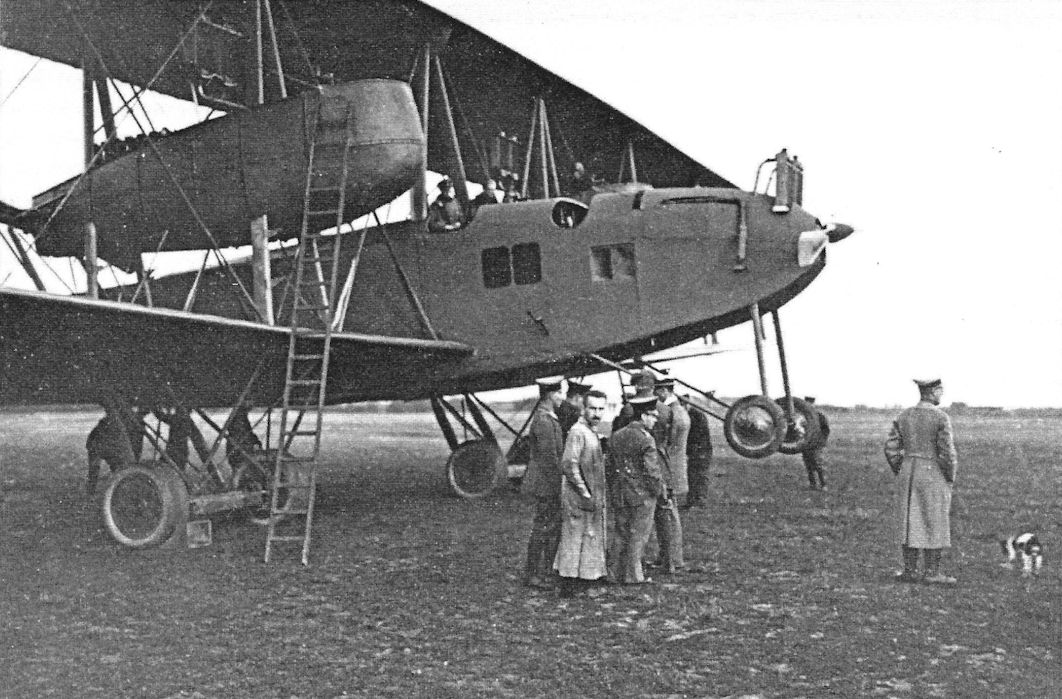
More views of the VGO.III R.10/15. It was a very large, impressive for the time. The overall configuration was conventionally similar to smaller biplanes. The aircraft's size and engine arrangement were the aspects that distinguished it from more common aircraft. (Peter M. Grosz collection/STDB)
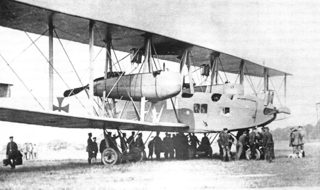
More views of the VGO.III being admired by a group of VIPs and guests. These views show the aircraft's details and massive size. (Peter M. Grosz collection/STDB)
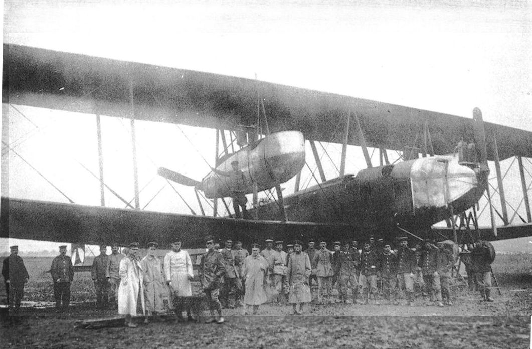
The VGO.III, 8 September 1916 on delivery to Rfa 500.
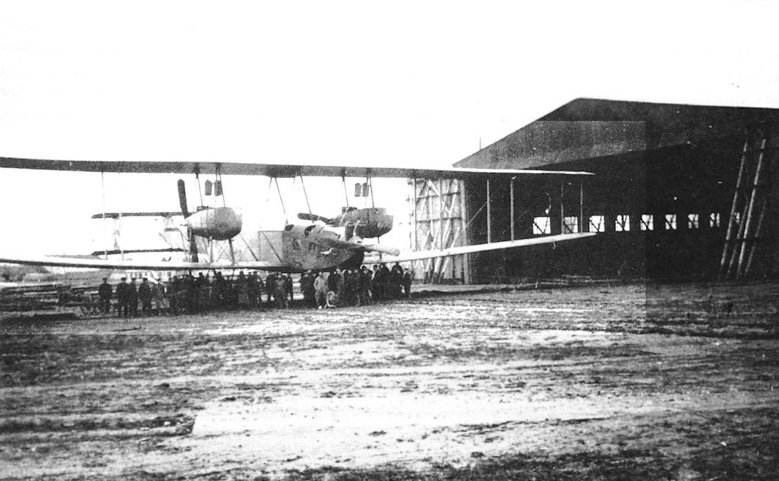
The VGO.III on the tracks outside its hangar at Alt-Auz, summer 1916.
The VGO.III being admired by a group of VIPs. (Peter M. Grosz collection/STDB)
The VGO.III being admired by a group of VIPs. (Peter M. Grosz collection/STDB)
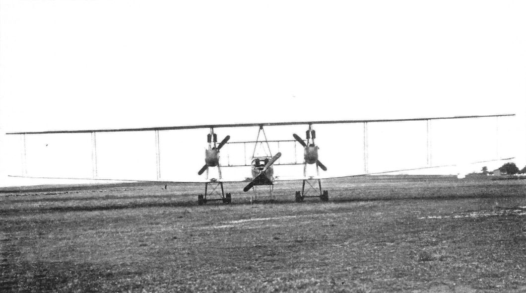
This full front view of the VGO.III shows the six radiators for the six 160 hp Mercedes D.III engines. (Peter M. Grosz collection/STDB)
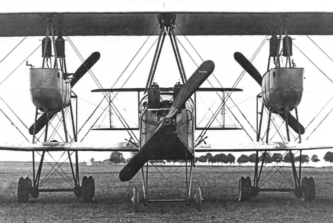
This front view of the VGO.III shows the six radiators for the six 160 hp Mercedes D.III engines. This change in engines was to improve reliability by replacing the Maybach HS engines that caused so many problems. The radiators exhibit a great deal of flat-plate area, creating a lot of drag. The central fixed fin of the VGO.II was replaced by enlarged fins attached to the rudders. Other than these detail changes, the VGO.III closely resembled the earlier VGO aircraft. (Peter M. Grosz collection/STDB)
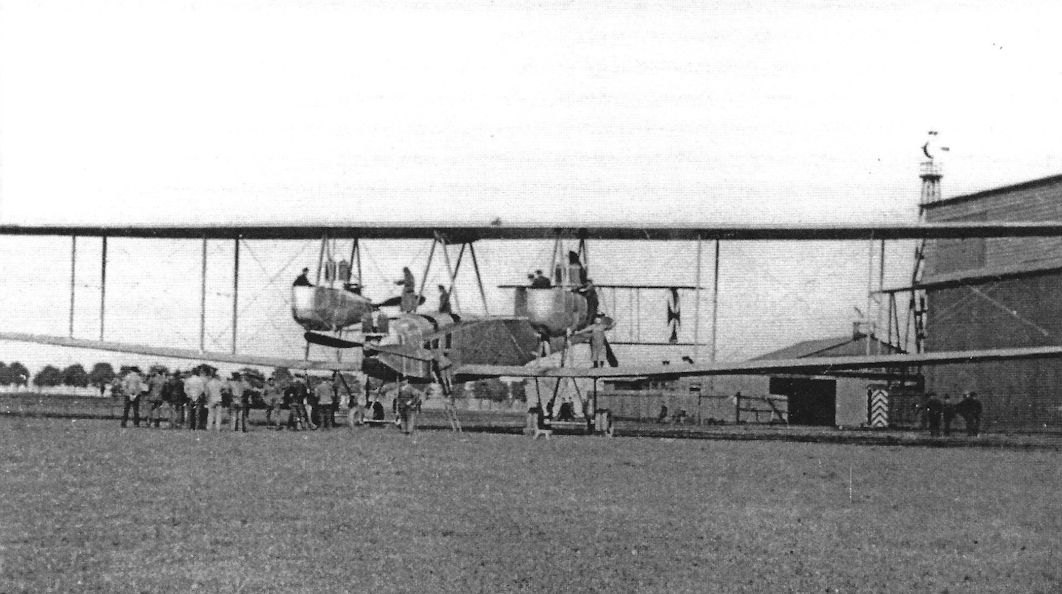
The VGO.III being admired by a group of VIPs and guests. These views show the aircraft's details and massive size. (Peter M. Grosz collection/STDB)
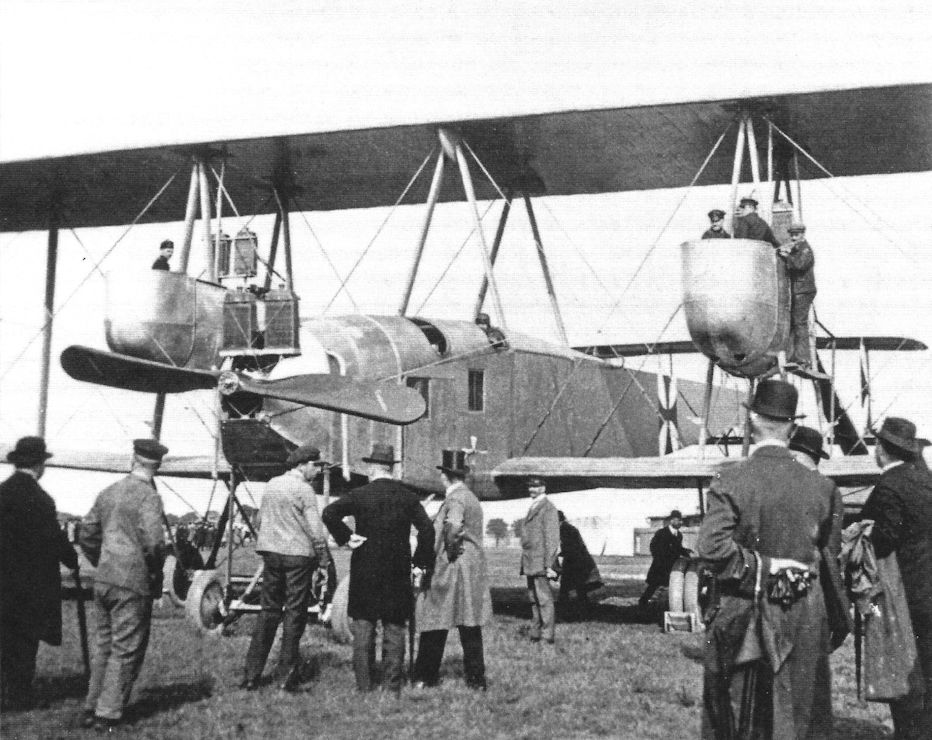
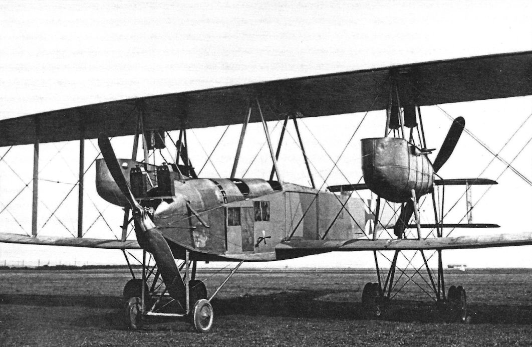
More views of the VGO.III being admired by a group of VIPs and guests. These views show the aircraft's details and massive size. (Peter M. Grosz collection/STDB)
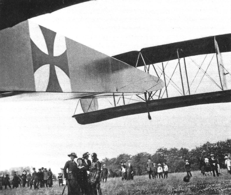
The VGO.III being admired by a group of VIPs and guests. These views show the aircraft's details and massive size. (Peter M. Grosz collection/STDB)
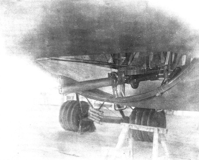
The ventral gun position on a Staaken. From the VGO.II all Staaken bombers had this defensive gun mounting. The British Lewis aircraft machine gun as shown here was very popular in giant bomber crews. (Peter M. Grosz collection/STDB)
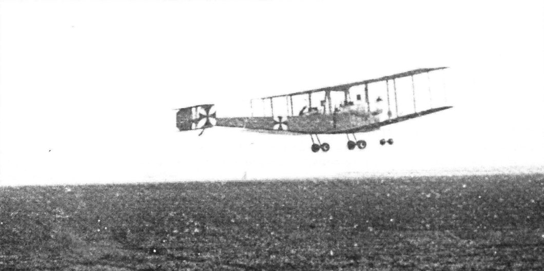
The VGO.III R.10/15 takes off an another flight. (Peter M. Grosz collection/STDB)
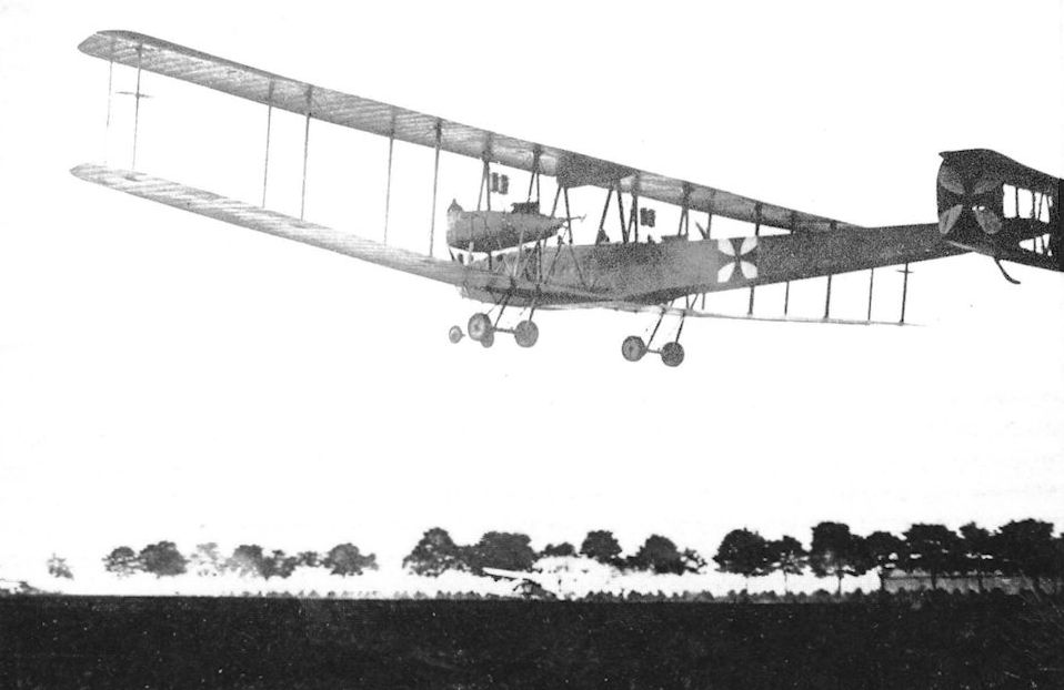
VGO.III 10/15 taking off from Gotha to fly to Doberitz, August 1916
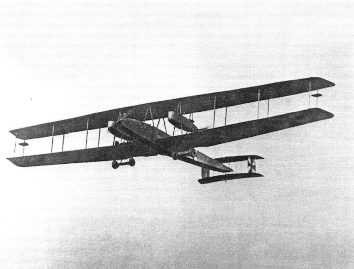
During flight testing the VGO.III was fitted with an auxiliary aileron balance on the rear outer interplane struts. These surfaces were designed to reduce aileron control forces to improve aileron response and reduce pilot fatigue. The surfaces were hinged aft of their center and connected to the ailerons. Similar methods of aileron balancing were tried by Gotha and Brandenburg seaplanes. However, the surfaces were removed from the VGO.III and not used on other Staaken aircraft. (Peter M. Grosz collection/STDB)
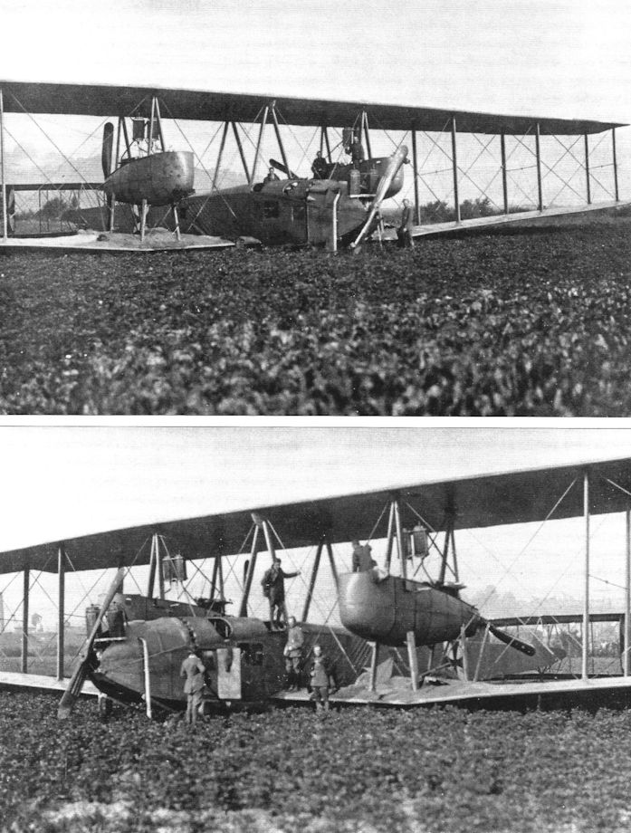
The VGO.III R.10/15 after its landing gear collapsed on landing. (Peter M. Grosz collection/STDB)
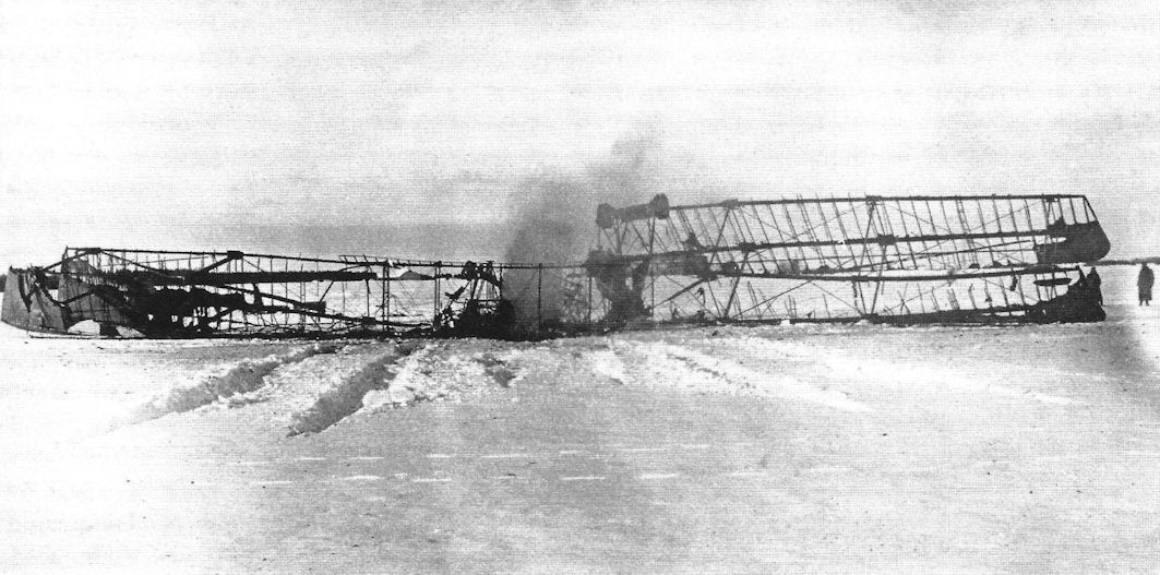
The charred remains of VGO.III after it crashed and burned on landing on January 24, 1917 at Alt-Aus on the Eastern Front. This was the first fatal accident in an R-plane. (Peter M. Grosz collection/STDB)
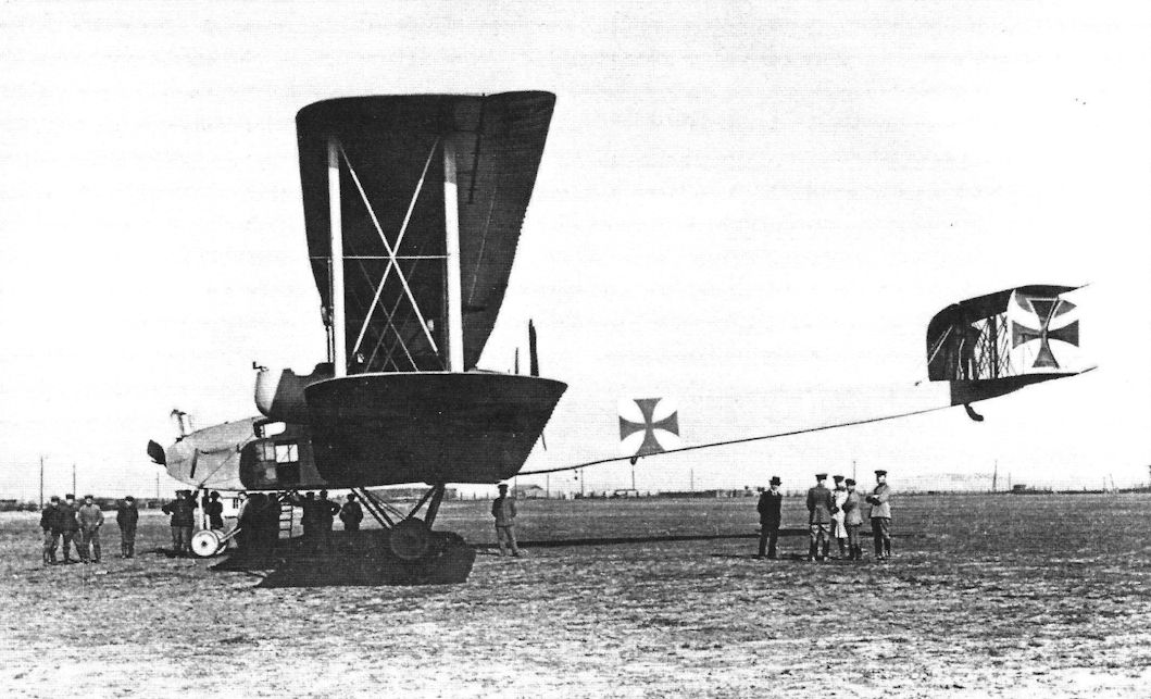
Photo showing Staaken R.IV freshly delivered to Rfa 500 on the Eastern Front. After the fuel tanks were full the aircraft sat on its front wheels. At this point the R.IV did not have its upper wing guns. Note the small cooling openings at the front of the nacelles. (Peter M. Grosz collection/STDB)
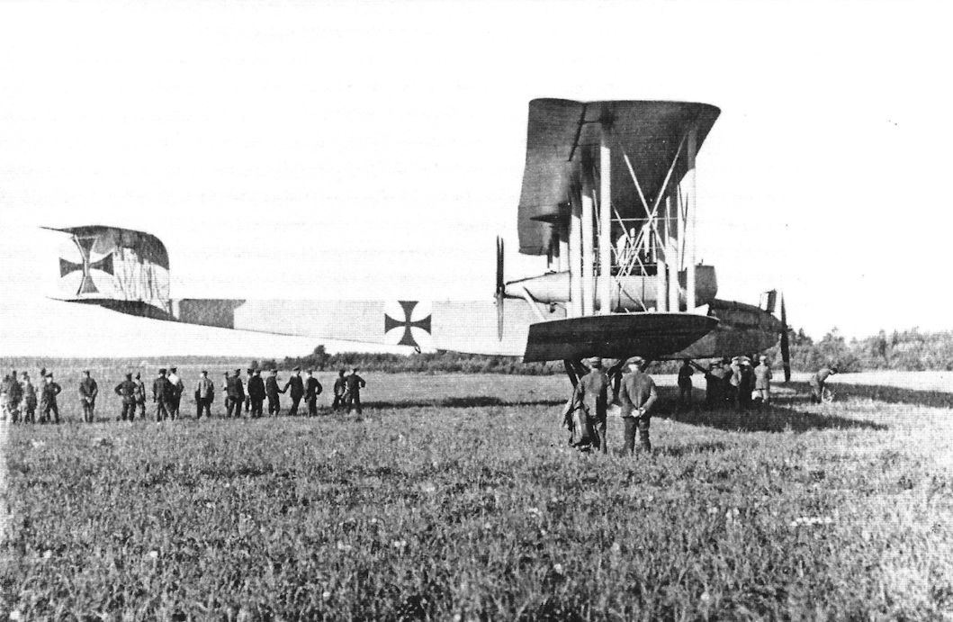
Staaken R.IV 12/15, here seen at Alt-Auz early in its long operational career.
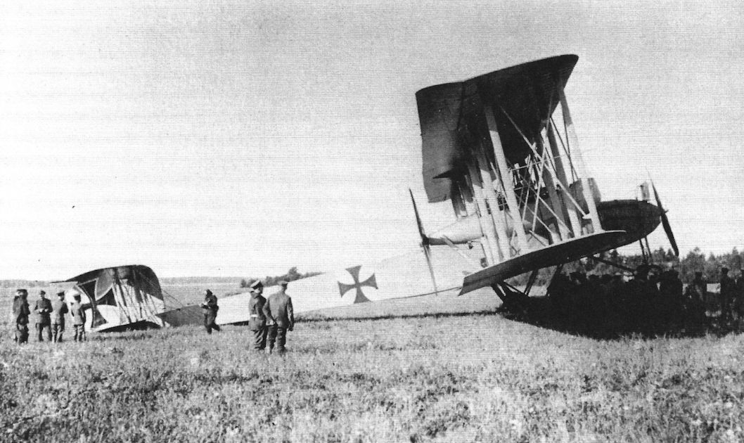
Photo showing Staaken R.IV freshly delivered to Rfa 500 on the Eastern Front. The personnel exercise in the massive aircraft's shadow. (Peter M. Grosz collection/STDB)
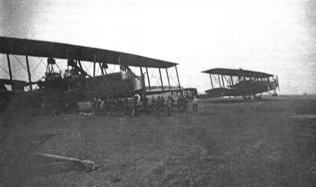
Staaken R.VI R.25 at the left together with another Staaken, probably R.12, on the airfield. (Peter M. Grosz collection/STDB)
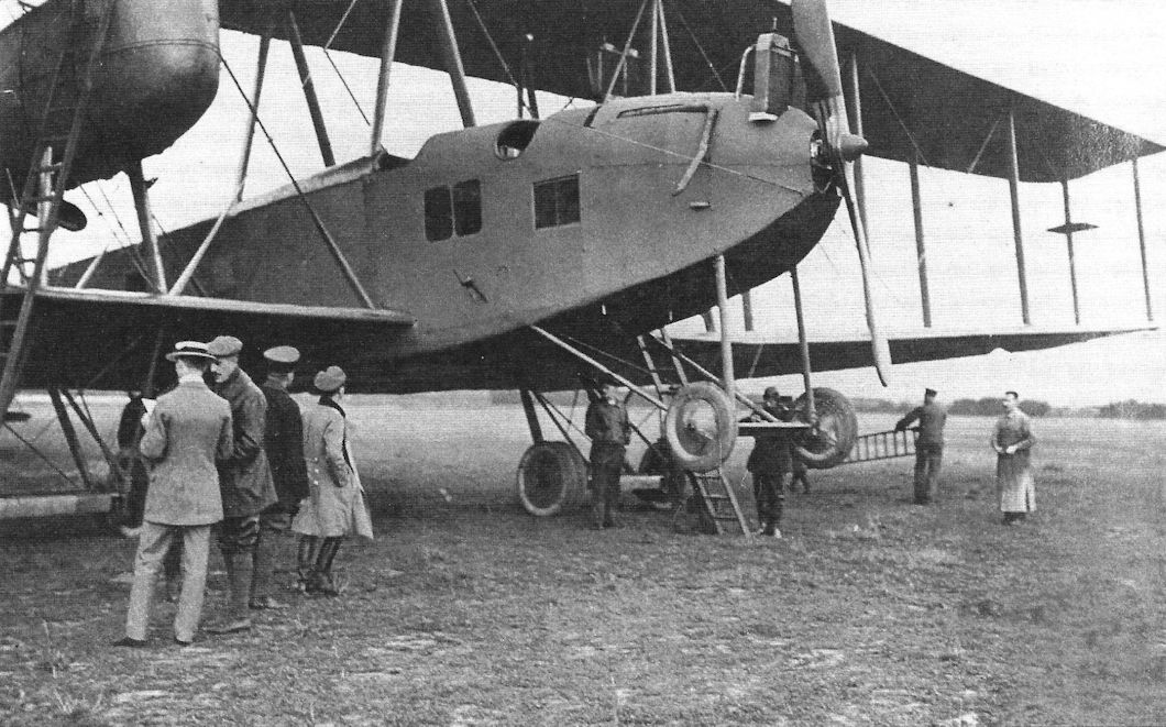
The R.12 being admired by guests before camouflage was applied. (Peter M. Grosz collection/STDB)
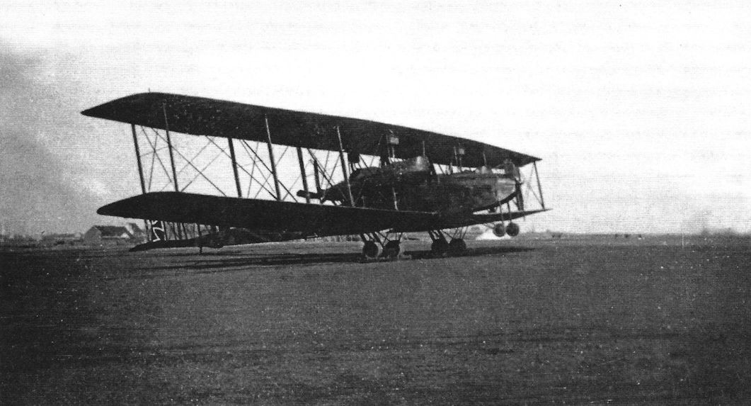
R.12 during service with Rfa 501 on the Western Front at Schweldewindeke airfield. R.12 previously served with Rfa on the Eastern Front, then was upgraded with wing gun positions, parachutes, and over-painted with night camouflage white outlined patee crosses in the normal positions. (Peter M. Grosz collection/STDB)
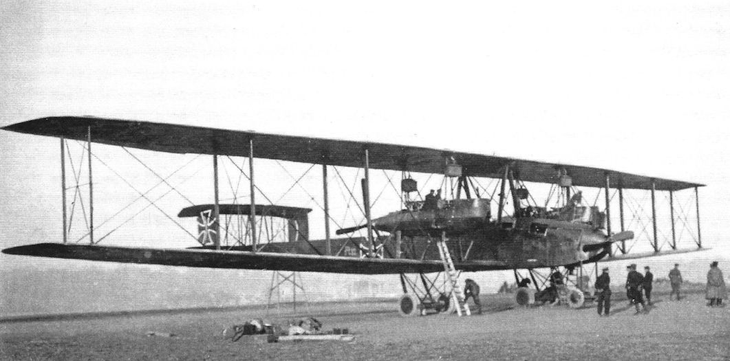
Staaken R.IV R.12/15 was the single most successful R-plane; here its crew pre-flights it for another mission at Schweldewindeke airfield. R.12 wears night camouflage with white outlined patee crosses and light painted R.12/15 on fuselage side. R.12 is shown prior parachute mounting. (Peter M. Grosz collection/STDB)
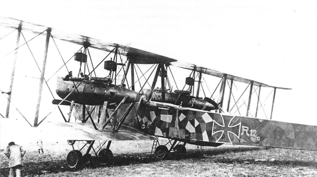
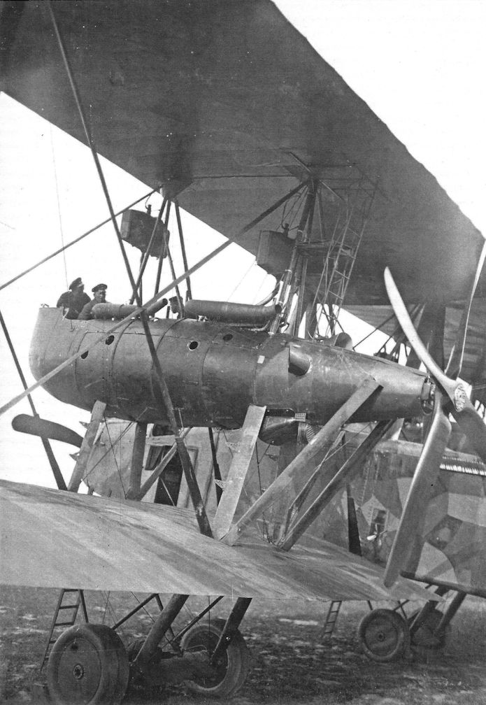
R.12 after parachutes were mounted; the parachute lines are visible on the fuselage side. The nacelle gunners and mechanics also appear to have parachutes in the fuselage. Tractor propellers prevented parachute use from the nacelles. Two big exhaust silencers direct the exhaust out of the engine. (Peter M. Grosz collection/STDB)
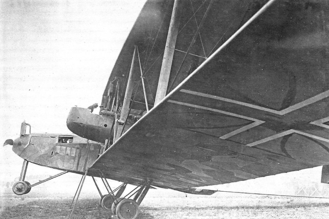
Staaken R.lV 12/15. The only R-plane to see action on both the Eastern and Western Fronts.
R.12 after parachute mounting and new camouflage. The antenna wire seen near bottom machine gun platform show that radio room was located just behind the bomb bay and main fuel tanks. Note the old patee crosses over-painted by black and new Balkenkreuze that were applied. (Peter M. Grosz collection/STDB)
R.12 after parachute mounting and new camouflage. The antenna wire seen near bottom machine gun platform show that radio room was located just behind the bomb bay and main fuel tanks. Note the old patee crosses over-painted by black and new Balkenkreuze that were applied. (Peter M. Grosz collection/STDB)
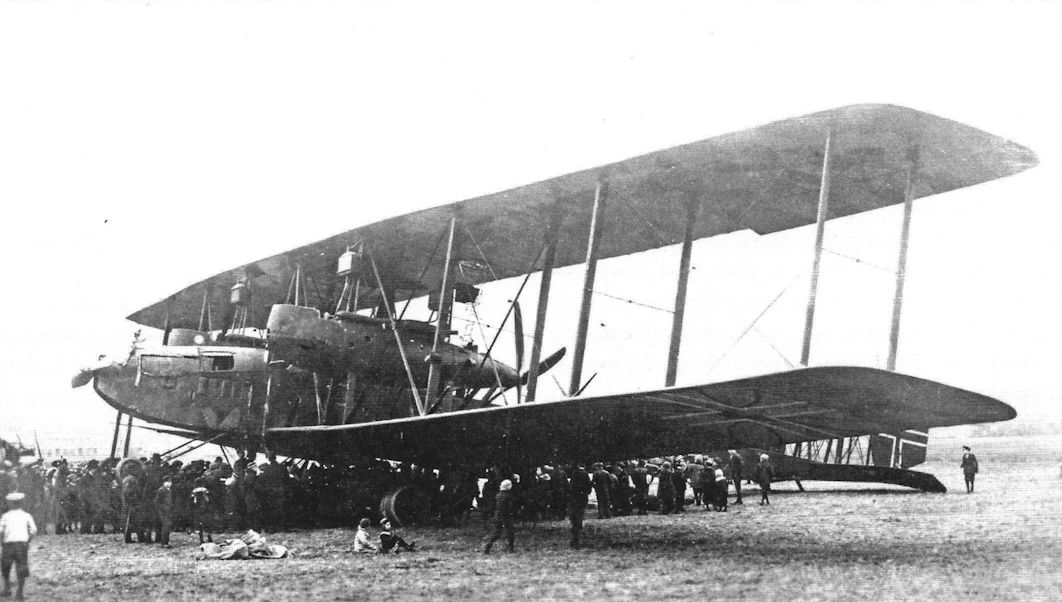
The Staaken R.IV was nearly identical in layout to the VGO.III, although the 160 hp Mercedes engines in the nacelles were replaced by more powerful 220 hp Benz Bz.IV engines. However, the aircraft looks different in this post-war photo due to its dark camouflage for night bombing at Western Front and the late-war style national insignia. (Peter M. Grosz collection/STDB)
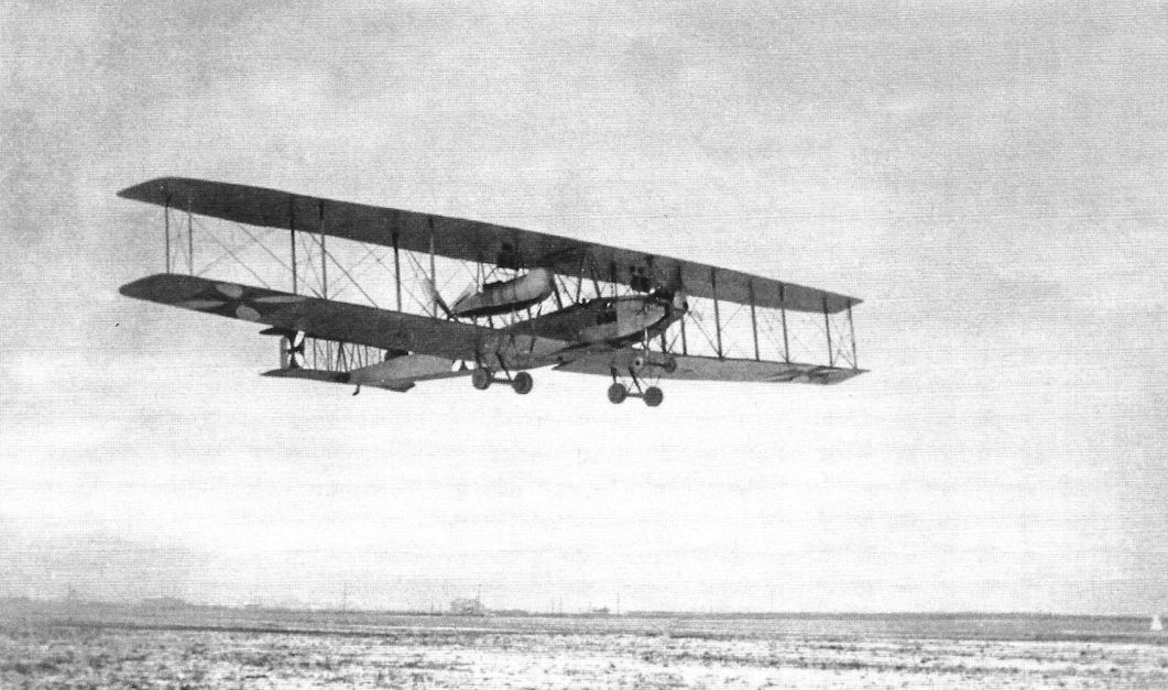
Staaken R.IV 12/15 during service with Rfa 500 on the Eastern Front. It is in its initial construction form without camouflage and with painted black patee crosses on white squares. (Peter M. Grosz collection/STDB)
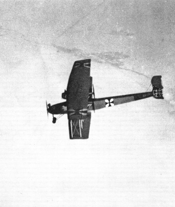
The R.12 in flight. (Peter M. Grosz collection/STDB)
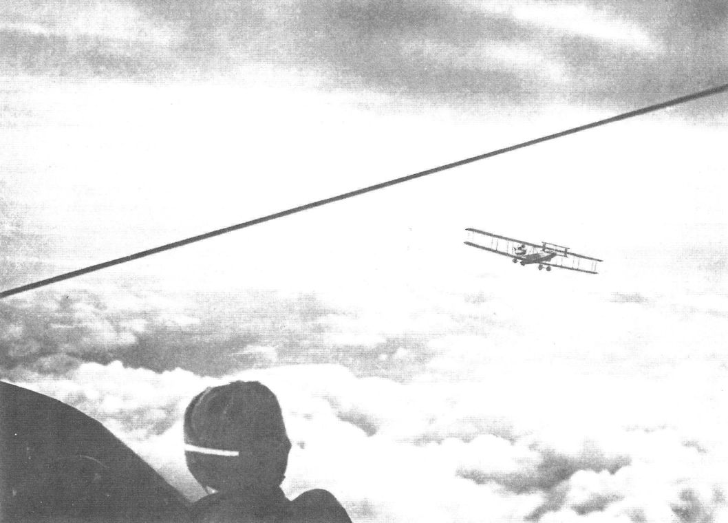
Another Staaken photographed from the Staaken R.IV in flight. (Peter M. Grosz collection/STDB)
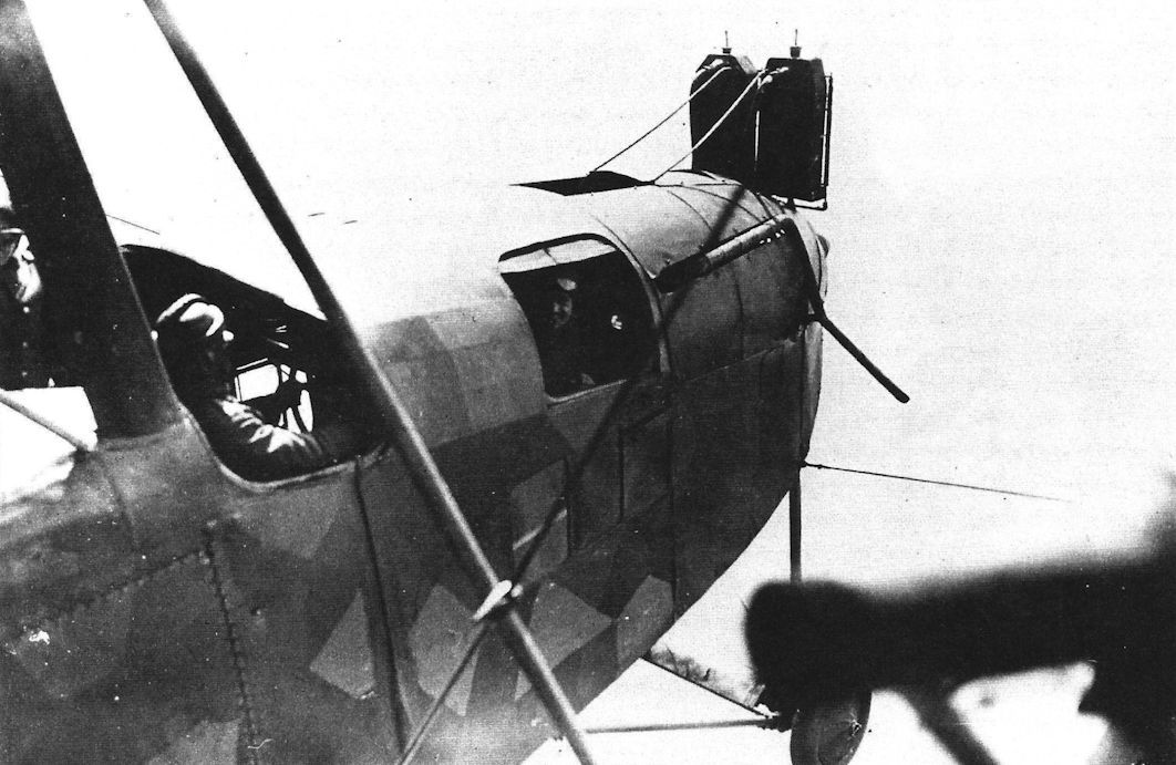
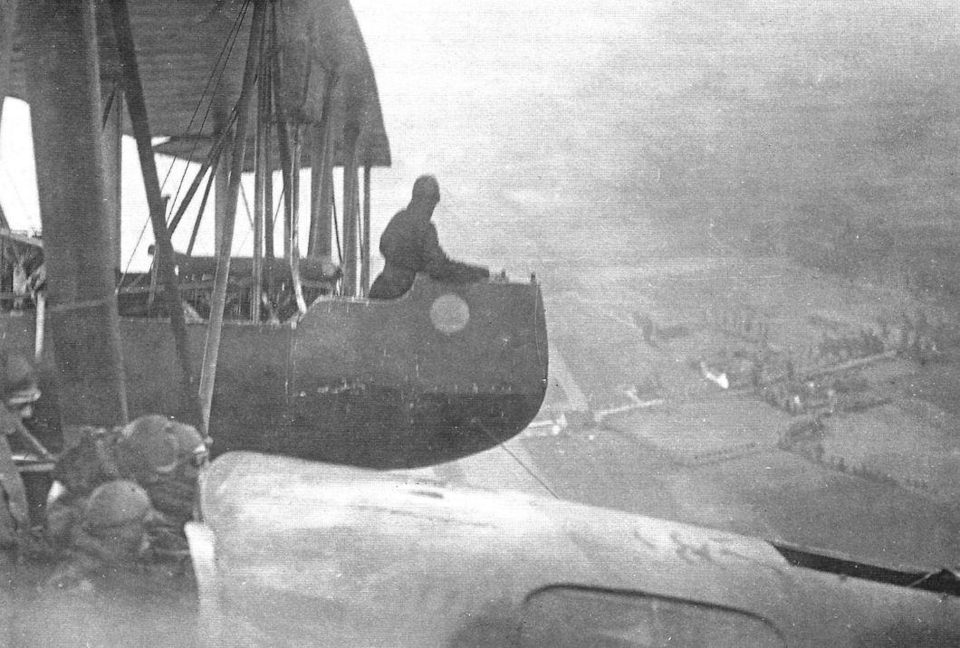
In-flight views of R.12 taken from the starboard nacelle gun position. (Peter M. Grosz collection/STDB)
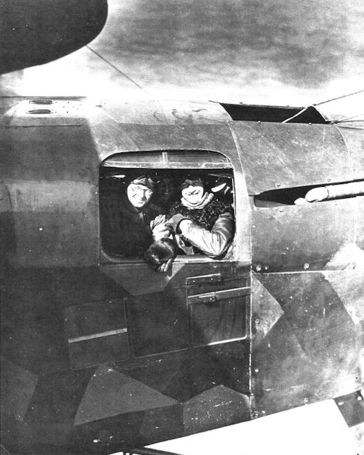
In-flight view of the R.12 taken from the starboard nacelle gun position. (Peter M. Grosz collection/STDB)
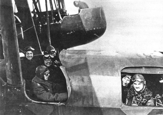
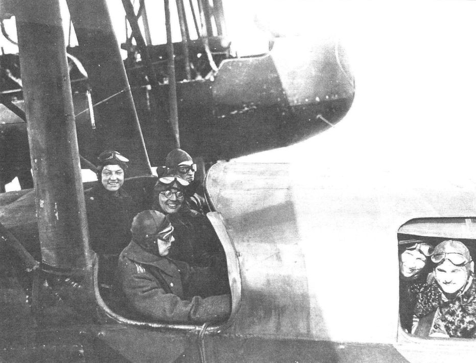
In-flight view of the R.12 taken from the starboard nacelle gun position. (Peter M. Grosz collection/STDB)
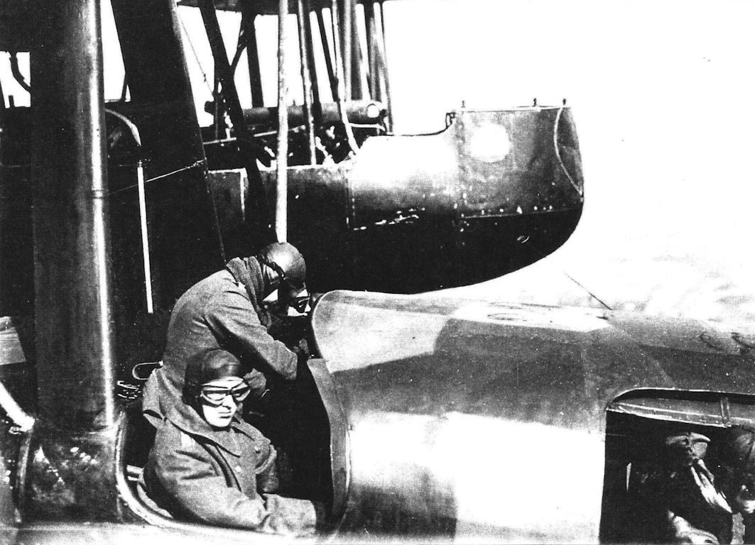
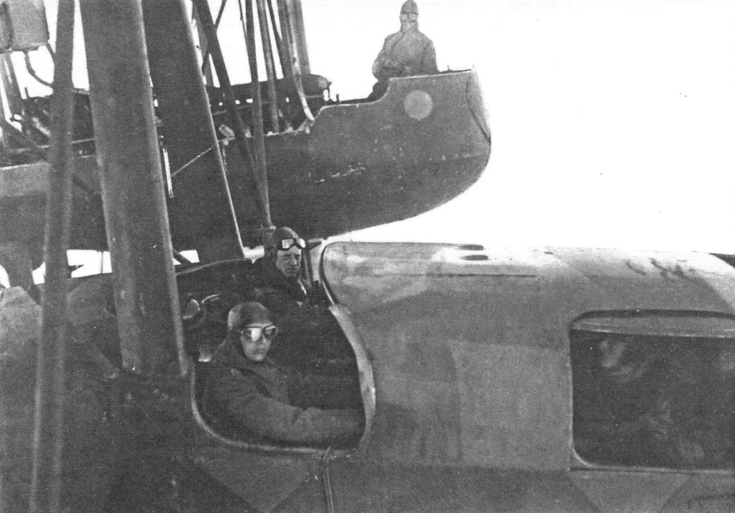
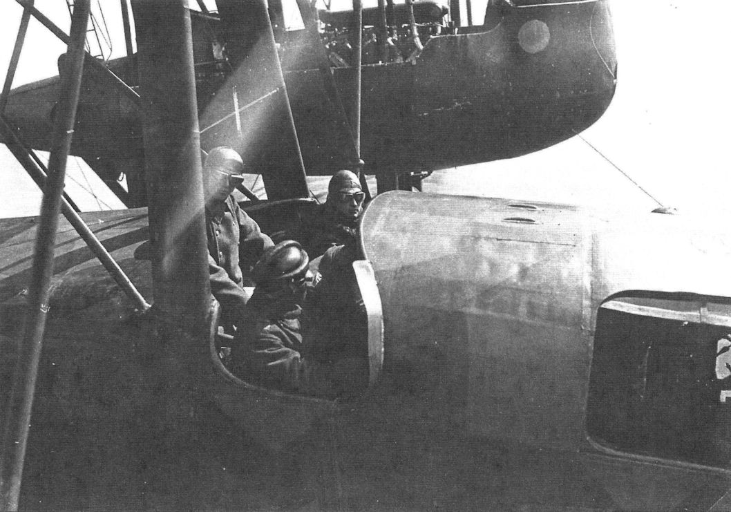
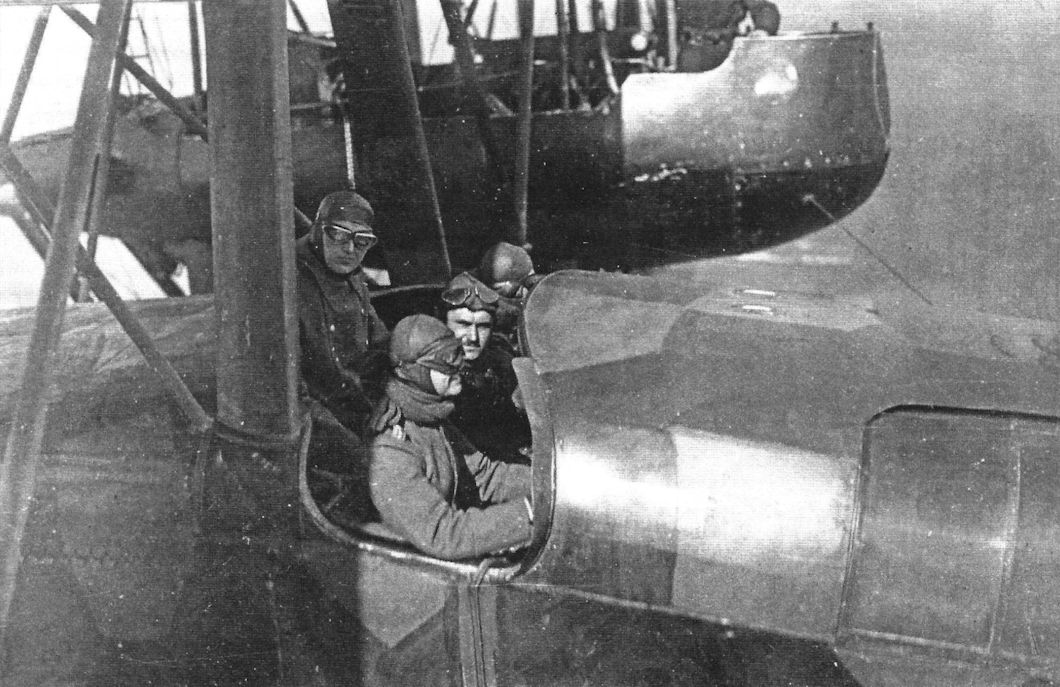
In-flight views of R.12 taken from the starboard nacelle gun position. The photo shows the pilots and plane commander; the static line for a parachute is visible sewn to the fuselage side. (Peter M. Grosz collection/STDB)
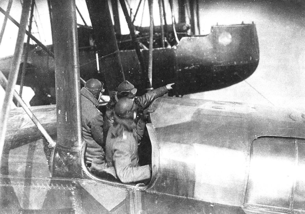
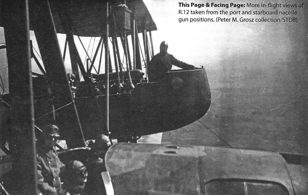
More in-flight views of R.12 taken from the port and starboard nacelle gun positions. (Peter M. Grosz collection/STDB)
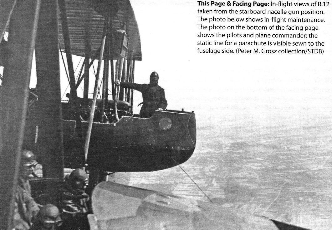
In-flight views of R.12 taken from the starboard nacelle gun position. (Peter M. Grosz collection/STDB)
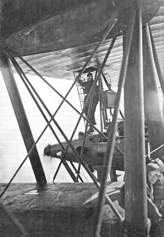
In-flight view of a gunner climbing up to the port over-wing gun position in the R.12. (Peter M. Grosz collection/STDB)
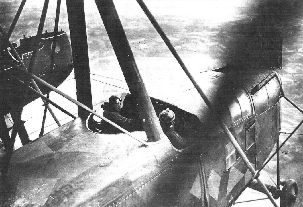
THE NOSE OF A GERMAN GIANT AEROPLANE. - Photograph taken from the port engine nacelle.
In-flight view of the R.12 taken from the starboard nacelle gun position. (Peter M. Grosz collection/ STDB)
In-flight view of the R.12 taken from the starboard nacelle gun position. (Peter M. Grosz collection/ STDB)
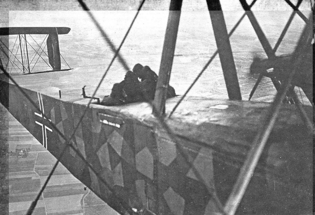
ON BOARD A GERMAN GIANT AEROPLANE. - Photograph showing view looking aft from the port engine nacelle.
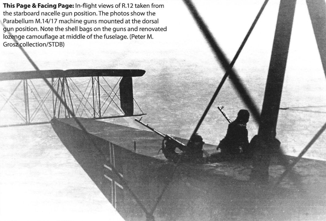
In-flight views of R.12 taken from the starboard nacelle gun position. The photos show the Parabellum M.14/17 machine guns mounted at the dorsal gun position. Note the shell bags on the guns and renovated lozenge camouflage at middle of the fuselage. (Peter M. Grosz collection/STDB)
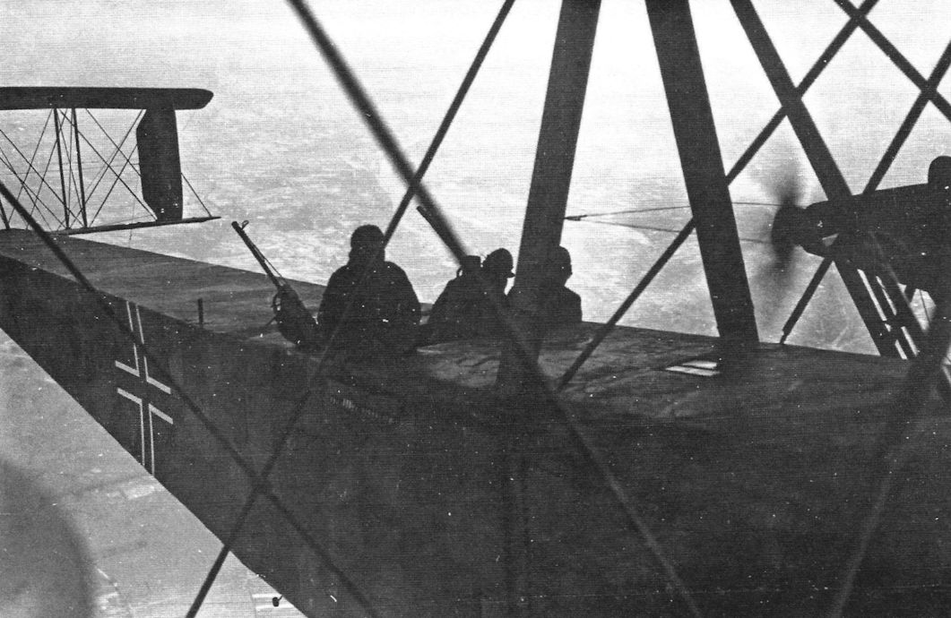
More in-flight views of R.12 taken from the starboard nacelle gun position. (Peter M. Grosz collection/STDB)
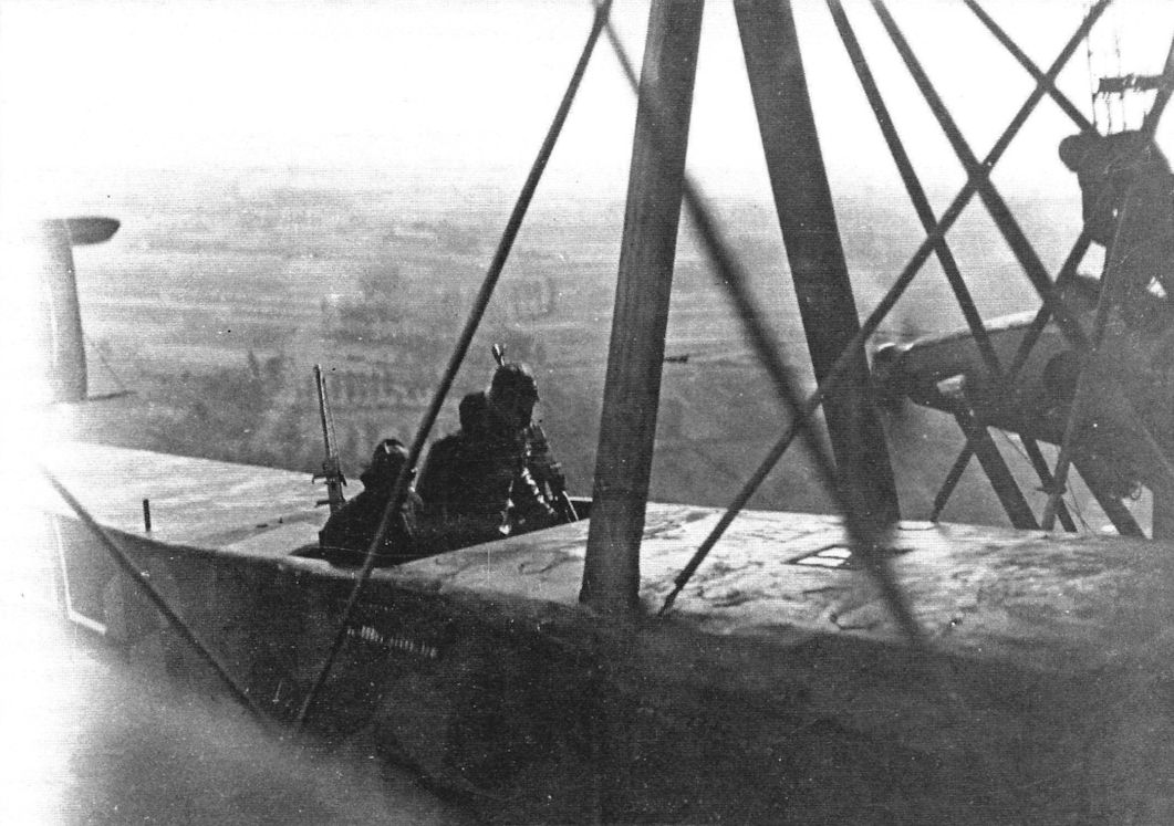
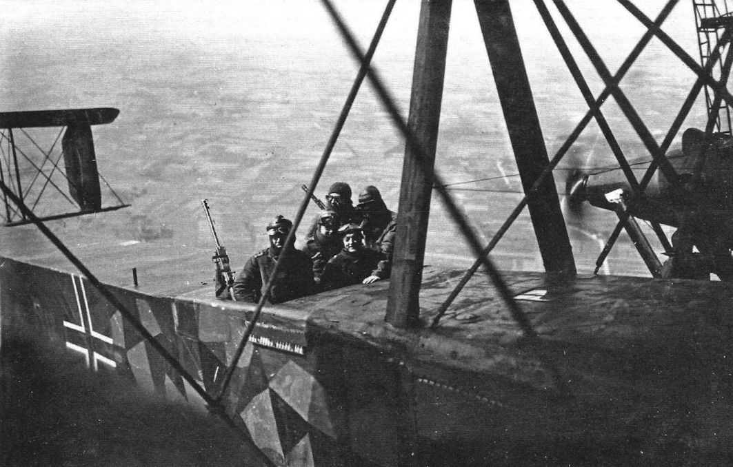
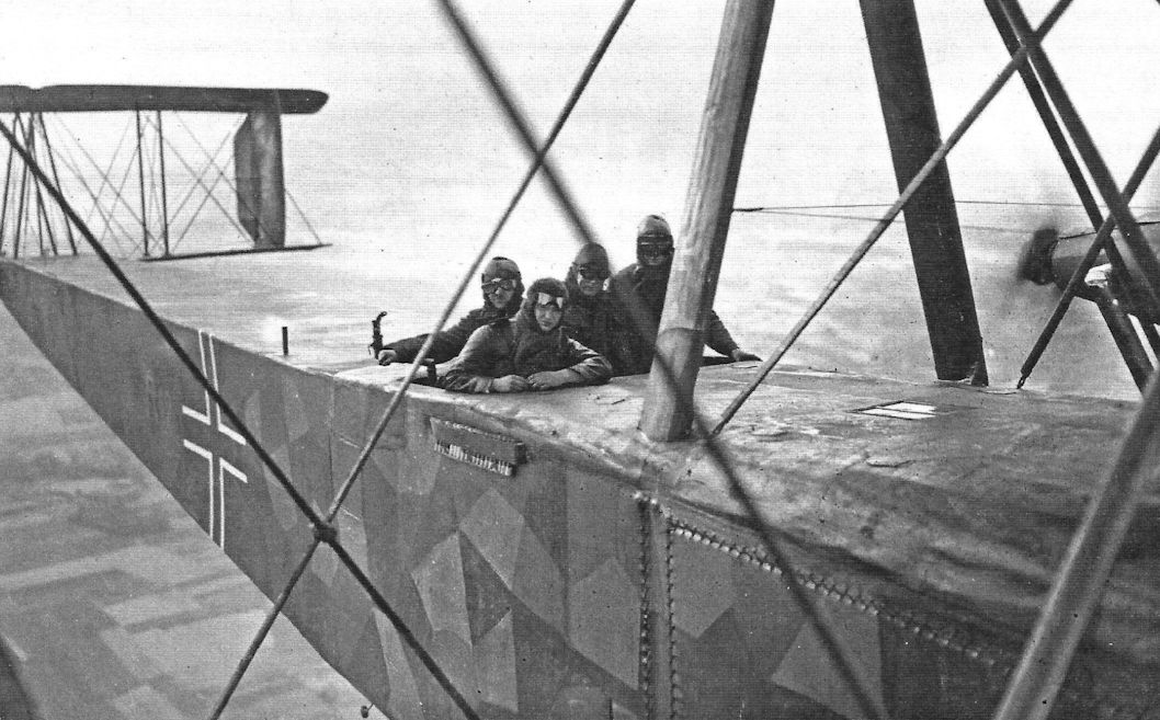
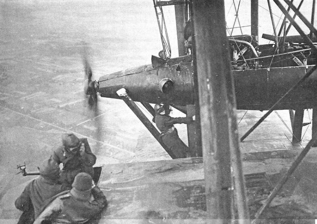
ON BOARD A GERMAN GIANT AEROPLANE. - The mechanic is repairing an oil pump defect during flight. The photograph was taken from the port engine nacelle.
In-flight views of R.12 taken from the starboard nacelle gun position. The photo shows in-flight maintenance. (Peter M. Grosz collection/STDB)
In-flight views of R.12 taken from the starboard nacelle gun position. The photo shows in-flight maintenance. (Peter M. Grosz collection/STDB)
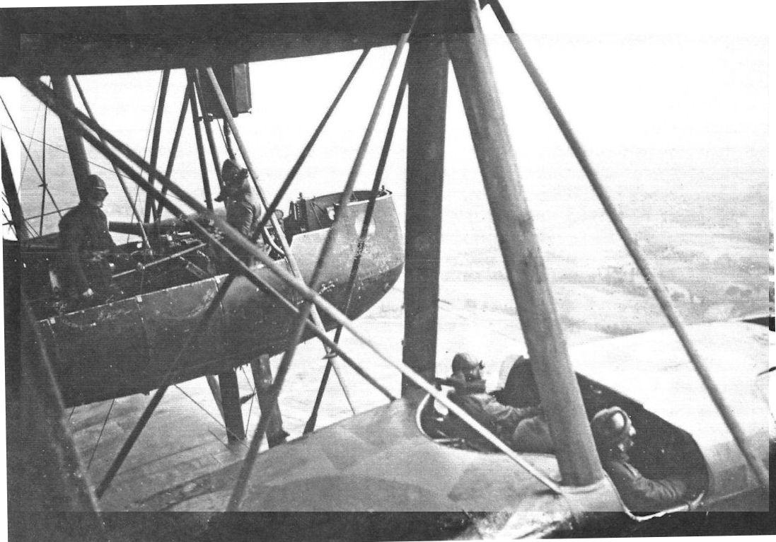
In-flight views of the R.12 taken from the starboard nacelle gun position. (Peter M. Grosz collection/STDB)
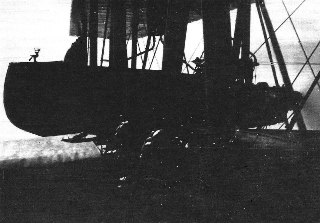
More in-flight views of R.12 taken from the port and starboard nacelle gun positions. (Peter M. Grosz collection/STDB)
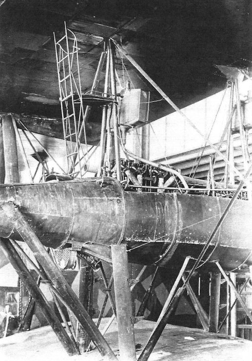
The over-wing gun position on R.12 and the ladder to climb to it. (Peter M. Grosz collection/STDB)
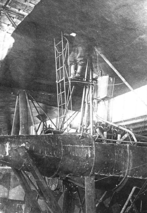
Right wing upper gun platform. (Peter M. Grosz collection/STDB)
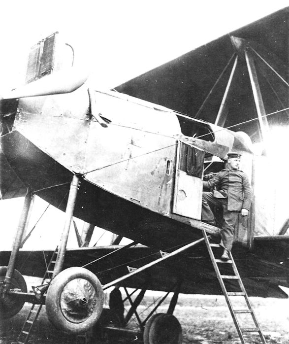
A ZEPPELIN GIANT. - The photograph shows how the fuselage is entered through a door in the side.
Crewman pauses at the R.12 entry door. (Peter M. Grosz collection/STDB)
Crewman pauses at the R.12 entry door. (Peter M. Grosz collection/STDB)
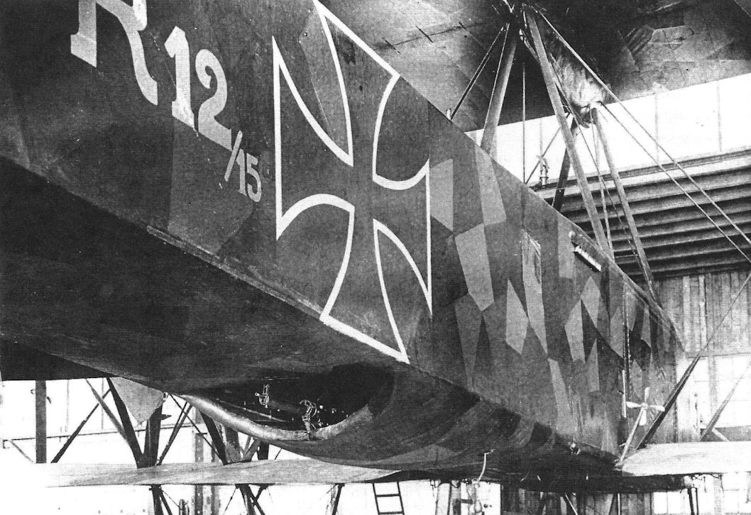
The camouflaged Staaken R.IV in the hangar.The ventral gun position with British Lewis machine gun is clearly shown. (Peter M. Grosz collection/STDB)
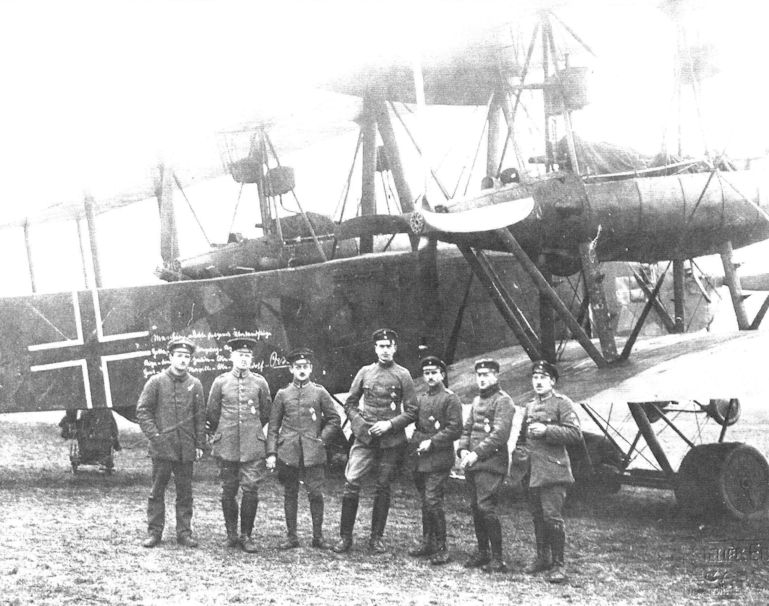
Staaken R.IV R.12/15 was the single most successful R-plane. In this postwar image the crew is photographed with the aircraft at Kassel; the targets, dates of the raids, and total weight of bombs are chalked on the fuselage.
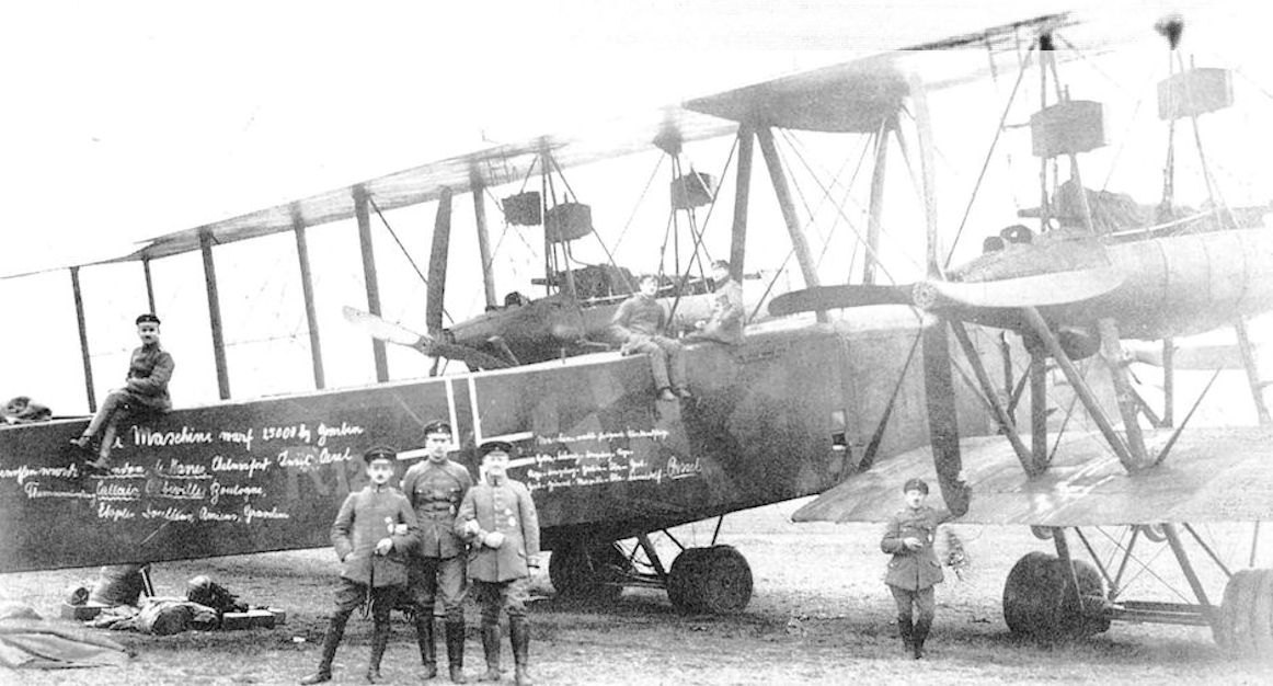
The Staaken R.IV and its crew at Kassel after the war. The targets attacked, the total weight of bomb dropped and places flown to have been chalked on the fuselage side.
The Staaken R IV 12/15 had the longest operational career of any machine in the R category, and was the only one to be flown on both the Eastern and Western Fronts, from May 1917 until the Armistice. It survived a collision with a balloon cable over London in February 1918 and dropped a total of 25,000kg of bombs. It is seen at Kassel in April 1919 with its fuselage inscribed with the names of the main targets attacked (including London, Harwich, Chelmsford, Oesel Island (Baltic), Calais, Abbeville, Boulogne, Etaples, Doullens and Amiens) and the routeing of several long-distance flights occasioned by ferrying from one theatre of operations to another; eg, Gotha-Doeberitz-Koenigsberg-Riga.
The Staaken R IV 12/15 had the longest operational career of any machine in the R category, and was the only one to be flown on both the Eastern and Western Fronts, from May 1917 until the Armistice. It survived a collision with a balloon cable over London in February 1918 and dropped a total of 25,000kg of bombs. It is seen at Kassel in April 1919 with its fuselage inscribed with the names of the main targets attacked (including London, Harwich, Chelmsford, Oesel Island (Baltic), Calais, Abbeville, Boulogne, Etaples, Doullens and Amiens) and the routeing of several long-distance flights occasioned by ferrying from one theatre of operations to another; eg, Gotha-Doeberitz-Koenigsberg-Riga.
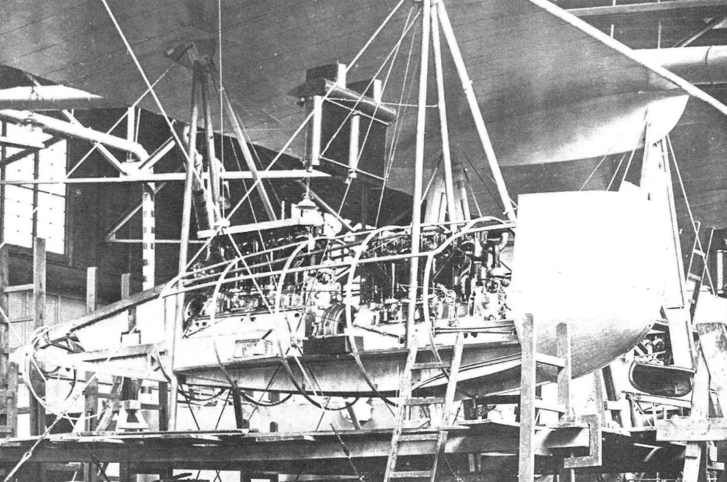
R.IV during assembly. At front or the picture not completed engines nacelle. Note the characteristic for Staaken nacelles, wooden bed for two engines coupled in one gearbox with light aluminium rib structure holding aluminum covers. Initial of radiators are visible, after first flights these were changed for better Hans Window type. (Peter M. Grosz collection/STDB)
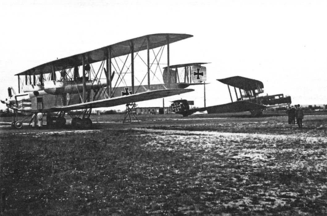
Staaken R.26/16 at right and R.VII R.14 on the left. (Peter M. Grosz collection/STDB)
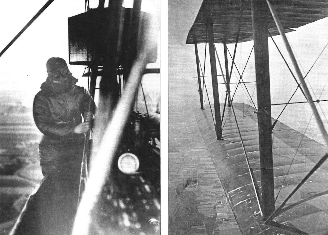
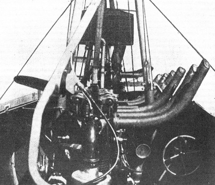
Engine nacelle of a Staaken bomber.
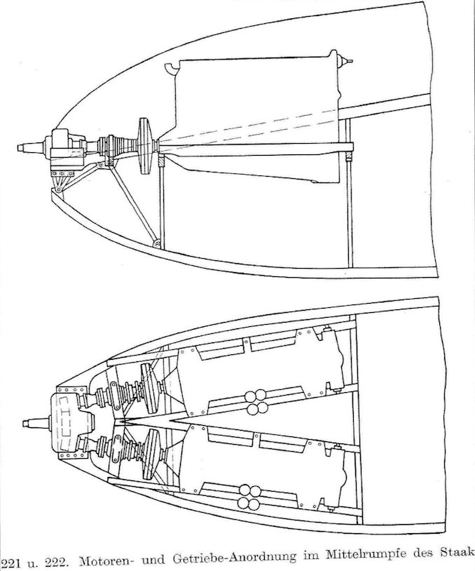
Drawing of the nose engines installed in the Staaken R.IV.
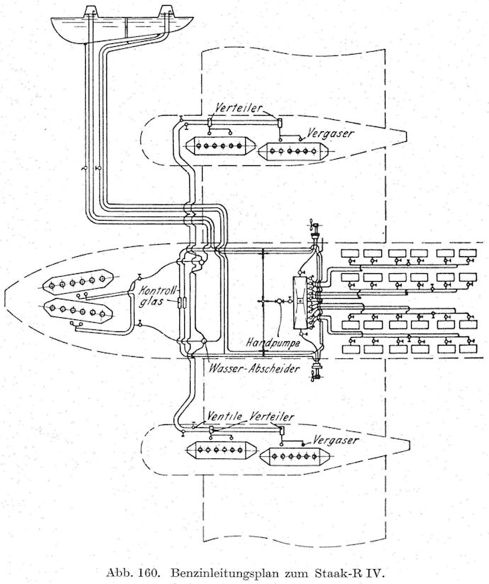
Diagram of the fuel system of the Staaken R.IV.
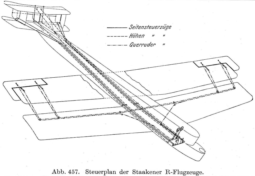
Diagram of the control system of the Staaken R.IV.
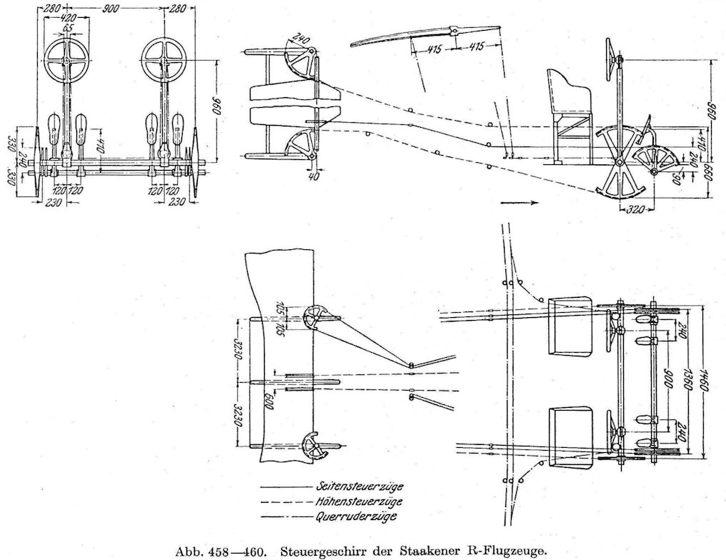
Diagram of the control system details of the Staaken R.IV.
Staaken Specifications
Type R.XVI L 8301 & 8303
Engines 2x500 Hp Benz Bz.VI 2x220 Hp Benz Bz.FV 4x260 Hp Mercedes D.IVa 4x260 Hp Mercedes D.IVa
Span 42.2 m (138' 5 1/2") 42.2 m (138' 5 1/2") 42.2 m (138'5 1/2")
Chord (max.) - 4.53 m( 14' 10") -
Gap (max.) - 4.55 m (14' 11") -
Length 22.5 m (73' 10") 22.2 m (72' 10") 21 m (68' 10 1/2")
Height 6.5 m (21'4") 7.38 m (24' 2 1/2") 6.8 m (22'3 1/2")
Wing Area 340 m2 (3,658 ft2) 360 m2 (3,874 ft2) 340.5 m2 (3,663 ft2)
Wt. Empty 10,400 kg (22,932 lb.) 8,400 kg (18,522 lb.) 9,000 kg (19,845 lb.)
Wt. Fuel - 2,445 kg (5,391 lb.) -
Wt. Loaded 14,650 kg (32,303 lb.) 11,800 kg (26,019 lb.) 12,500 kg (27,563 lb.)
Max Speed 130 km/h (80.8 m/h) 125 km/h (77.7 m/h) 130 km/h (80.8 m/h)
Climb 1,000 m - 23.7 minutes (full load) -
Climb 1,780 m - 60 minutes -
Ceiling 3,710 m 2,500 m -
Duration - 10 hours -
The Staaken L & 8301/8303 were naval floatplanes derived from the R.VI. The 8301 & 8303 could climb to 3,000 m in 54 minutes.
Staaken R.VI
The military situation required more R-planes. Simultaneously, R-plane development coupled with operational experience had resulted in more mature R-plane technology, especially within the Staaken R-plane family. These trends combined with the development of the R.VI to enable mass production of the type, which was the only R-plane design mature enough to justify mass production at the time.
The Staaken R.VI retained the basic airframe of its predecessor, the R.V, and again was distinguished by a different engine arrangement. The R.VI was also distinguished by being built in quantity instead of remaining a single aircraft; this made the R.VI the largest aircraft type to be placed in mass production during WWI. Excluding the seaplane versions, 18 R.VI aircraft were produced during the war, 12 of them under license by other manufacturers.
The most visible difference between the R.VI and the Staaken R-planes that came before it was the elimination of the nose engine or engines and associated propeller and engine nacelles with both pusher and tractor engines and propellers. This change had been dictated by operational experience. The nose-mounted propeller required a tall nose landing gear, and that increased the chances of nosing over during hard landings or on rough fields. Moreover, after the crash of VGO.III, a nose engine was thought to increase the likelihood of fire during a mishap due to the proximity of the nose engine to the fuel tanks in the fuselage. Elimination of the nose propeller allowed a shorter nose landing gear that was safer during landing. The shorter nose landing gear enabled a shorter, more robust main landing gear to be used. However, its normal ground attitude of the R.VI was to rest on its tail skid.
The use of both pusher and tractor propellers in the same engine nacelle was driven by the need to eliminate the cost, weight, and complexity (and its associated reliability issues) of the earlier power transmission systems of gearboxes and clutches. Reducing cost, weight, and complexity were necessary to make the improvements required to enable effective mass production. Moreover, maintaining the complex drive system during operation required highly-skilled flight crews, and this became more of a problem as engines of higher power were installed. Eliminating the complex power transmission systems alleviated these issues and drove the design team to choose the simplest power transmission system possible. The disadvantage was that the fixed-pitch propellers available could not be feathered to reduce the drag of a wind-milling propeller in case of engine failure. This was the problem that had driven most R-plane design teams to create centralized power systems that enabled the flight mechanic to de-couple failed engines from the propellers, but engine reliability had also improved.
For the engine nacelles, the R.VI design abandoned the wood semi-monocoque structure of the R.V that, despite its advantages, was costly to produce, especially in skilled labor. The R.VI engine nacelles were made of aluminum stringers covered by aluminum panels; the resulting structure was light and strong.
R.25, the first R.VI, was probably completed it late 1916 and was extensively test-flown before delivery to the air service on June 8, 1917. R.26 was delivered on July 20, 1917, very quickly after the delivery of R.25. The success of the R. VI during the evaluations flights enabled license-production contracts to Aviatik, Schutte-Lanz, and OAW (Ostdeutsche Albatroswerke).
Needing a lot of reliable power, the R.VI had four 260 hp Mercedes D.IVa engines. These newly-available engines were the most powerful, reliable engines available at the time. In addition to the Mercedes, the R.VI could also be powered by four 245 hp Maybach Mb.IVa engines. The Maybach Mb.IV was one of the first over-compressed production engines; it was designed to give its full power at 2,000 m altitude by increasing its compression ratio. Below 2,000 m the Maybach could not be run at full power due to detonation (premature ignition) that would quickly damage the engine. To produce 245 hp at 2,000 m a regular engine would need to be able to produce 300 hp at sea level. The Maybach was slightly less powerful than the Mercedes at low altitude but produced more power at higher altitudes where the missions were flown.
Although mounted separately and driving separate propellers, each engine was still geared down to produce lower propeller RPM, so the complex drive system used in prior designs was not completely eliminated. However, the new gearboxes were smaller and lighter than before. The engines and gearboxes were separated by a leather-metal coupling to reduce vibration and accommodate any misalignment. The propeller shaft of the rear engines was longer than those on the front engines to give the rear propellers enough clearance from the trailing edges of the wings. To provide cooling for the gearbox oil, each had a small radiator that extended into the slip-stream. Most propellers were made by Garuda; these were of spruce and ash laminations covered by a thin covering of plywood. Aviatik-built R.VI aircraft had propeller spinners.
Each engine had its own radiator mounted on the nacelle struts, with the radiators for the rear engines mounted higher than those for the front engines. The engines had self-starters because swinging the propellers by hand was not practical.
Fuel tanks were built into the fuselage. There were eight or ten of these, of 245 liters each. The tanks were suspended by steel bands from the upper fuselage structure, which was reinforced by welded steel tubes at this location to support the weight. A gangway enabled the crew to move along the fuselage and inspect the fuel tanks. Two propeller-driven fuel pumps mounted on either side of the fuselage decking near the wing roots pumped fuel into a 155 liter gravity tank located under the upper wing between the cabane struts. A quick-emptying valve on each main fuel tank enabled fuel to be jettisoned in an emergency. A crewman was assigned to maintain the fuel levels essentially equal in all main fuel tanks to preserve the aircraft's balance.
R.VI aircraft had ailerons on the upper wings only and normally were unbalanced. The Aviatik-built R.VI aircraft had ailerons with extended balance areas and the R.30 used ailerons of the R.XIV type. Initially the tail assembly did not have a central fin and rudder, but later this was added to improve control and stability.
Elimination of the engine and propeller in the nose enabled a flexible machine gun to be fitted there. The aircraft commander could also use the nose position to guide the aircraft during bombing runs. Other gun positions were fitted to the dorsal (two guns) and ventral positions like earlier types and some R.VI aircraft had the upper wing positions over the engine nacelles like the R.IV. However, folding panels replaced the sliding panels to fair the wing surfaces of the R.IV. The official equipment table for R-planes specified three Lewis guns as the normal armament for the R.VI; the captured Lewis guns were lighter than comparable German guns.
The central bomb bay was configured to carry 18 100 kg bombs in three rows, and 300 kg and 1,000 kg bombs could also be carried. However, the larger bombs protruded outside the aircraft. The typical bomb load was 1,000-1,200 kg, although a bomb load of 2,000 kg was possible if a reduced fuel load was carried. Typical flight duration was 7 hours; additional fuel tanks could be installed to stretch that to 10 hours. The longest missions were 800 km and the maximum operational range was 900 km with a reduced bomb load of 750 kg.
The typical crew was seven men; a commander/navigator, two pilots, a radioman (then called a wireless operator), two flight mechanics, and a fuel attendant (today the nomenclature for these last three would be flight engineer). Additional gunners could be carried if thought necessary but this was rare.
The R.VI was used from its introduction to the end of the war. Many were destroyed in operational accidents; 7 of the 18 built were destroyed in crash-landings, one was lost due to engine failure during take-off, and one was lost due to extreme flight maneuvers the airframe was not designed for. Aviation technology, procedures, and navigational aids were early in their development and the larger R-planes were as susceptible to these dangers as smaller aircraft.
Only two R-planes were shot down in combat. In both cases, the aircraft were being used for short-range missions just behind the lines, making them easier for the defending night fighters to find. These missions were undertaken late in the war when the longer-range missions the R-planes were designed for were abandoned for tactical missions due to the increasingly desperate situation on the ground. No R-plane was shot down during the long-range night bombing missions the R-planes were designed to perform.
Staaken R.VI Details (Table 1 of 4)
Serial Manufacturer Engines Rudders Propellers Exhaust
R25 Staaken Mercedes 2 Two-bladed Garuda All in engine to one large exhaust header
R26 Staaken Mercedes 2 Four-bladed Garuda All in engine to one narrow Pipe
R27 Schutte-Lanz Mercedes 2 Two-bladed Garuda 6 narrow pipes in engine
R28 Schutte-Lanz Maybach 2, then 3 Two-bladed Garuda, small spinners 6 into one pipe
R29 Schutte-Lanz Maybach 3
R30 Staaken Mercedes 2, then 3 Two-bladed Garuda, small spinners 6 narrow pipes in engine
R31 Staaken Mercedes Two-bladed
R32 Staaken Maybach 2, then 3 Four-bladed Schwartz, small spinners 6 narrow pipes in engine
R33 Aviatik Mercedes 2 Two-bladed Garuda, spinners All in engine to one large exhaust header
R34 Aviatik Mercedes 2 Two-bladed Garuda, spinners All in engine to one large exhaust header
R35 Aviatik Mercedes
R36 OAW Mercedes Two-bladed Garuda, spinners 6 narrow pipes in engine
R37 OAW Maybach 3 Two-bladed
R38 OAW Mercedes 3
R39 Staaken Maybach 2 Two-bladed 6 into one
R52 Aviatik Maybach Two-bladed, spinners 6 into one
R53 Aviatik Maybach
R54 Aviatik Maybach
Mercedes = 260 hp Mercedes D.IVa; Maybach= 245 hp Maybach Mb.IVa
Staaken R.VI Details (Table 2 of 4)
Serial Nacelle Struts Special Features
R25 All wide
R26 Top and bottom outside thin, bottom inside wide
R27 All thin
R28 Top and bottom outside thin, bottom inside wide Upper wing guns
R29 Upper wing guns
R30 Top and bottom outside thin, bottom inside wide Upper wing guns, Supercharger
R31
R32 Top and bottom outside thin, bottom inside wide
R33 Top and bottom outside thin, bottom inside wide White outlined Eisern crosses only. White "Der Laurige Hund" badge on nose
R34 Top and bottom outside thin, bottom inside wide
R35 Supercharger?
R36 Top and bottom outside thin, bottom inside wide
R37
R38
R39 Top and bottom outside thin, bottom inside wide
R52
R53
R54
Staaken R.VI Details (Table 3 of 4)
Serial Paint Paint & Construction Changes
R25 Hand painted, four colors, darken from top and bottom by dark blue paint(?) Extra wireless dynamo mounted on the LH front centre-section strut
R26 Hand painted, four colors, darken from top and bottom by dark blue paint(?) Different propellers, two 300 kg bomb carriers
R27 Hand painted, four colors, darken from top by transparent black paint, bottom wings without Extra wireless dynamo mounted on the RH front centre-section strut
R28 Hand painted, four colors, darken from top by transparent black paint, bottom wings without
R29
R30 All canvas printed five colors, night pattern lozenge Extra windows on the fuselage sides, Helix controllable pitch propellers
R31 Extra window on the front of the roof, two 300 kg bomb carriers
R32 Hand painted, four colors, darken from top and bottom by dark blue paint(?)
R33 Hand painted, four colors, darken from top by transparent blue paint, bottom wings without Extra wireless dynamo mounted on the RH front centre-section strut, front headers tube dismounted, extra windows
R34 Hand painted, four colors, darken from top and bottom by dark blue paint(?) Extra window on the front of the roof
R35
R36 All canvas printed five colors, night pattern lozenge Balanced ailerons, extra windows on the fuselage sides
R37 Hand painted, four colors, darken from top by transparent blue paint, bottom wings without Extra windows on the fuselage sides, two 300 kg bomb carriers
R38
R39 Hand painted, four colors, darken from top and bottom by black paint)?) Extra wireless dynamo mounted between the centre-section struts, two 300 kg bomb carriers
R52 All canvas printed five colors, night pattern lozenge "Glass house" cabin, new BuS.IVa engines, extra balanced ailerons
R53 All canvas printed five colors, night pattern lozenge
R54 All canvas printed five colors, night pattern lozenge
Staaken R.VI Details (Table 4 of 4)
Serial Lost Fate
R25 ? ?
R26 9/10 May 1918 Crash landed in fog and burnt at Scheldewindecke
R27 7/8 March 1918 Crash landed due to frozen fuel lines in Belgium, destroyed by enemy artillery after that
R28 1918 Crashed on take off, due to engine failure
R29 9/10 May 1918 Crashed into trees while landing in fog at Scheldewindeke
R30 - Survived the war
R31 15/16 Sept.1918 Crashed in flames at Beugny, possibly due to enemy fire
R32 9/10 May 1918 Crash landed in fog at Scheldewindeke and was destroyed by the bombs exploding ...
R33 ?
R34 20/21 April 1918 Crashed after possible enemy action,remains with one air mechanic body discouverd by Mr. Piet Steen at Poelkapelle mud field.
R35 ? Probably fitted with a supercharger March 1918
R36 7/8 March 1918 Dismanteld after a crash landing
R37 1/2 June 1918 Forced landing near Betz (France) after hits from French AA- fire, burned
R38 6-May-18 Crashed on a ferry flight near Heisingen (Germany) after loosing orientation
R39 - Survived the war, possibly the most successful R-plane, dropping 26,000 Kg of bombs in 20 raids
R52 11/12 Aug. 1918 RFA 500, Crashed and burnt at Villers la Tour (France)
R53 - Discovered in 1919 by ICCIA at Staaken/Doberitz, Helle 12
R54 -
Staaken Specifications
Type R.VI R.VI R.VI 30/16
Engines 4x260 Hp Mercedes D.IVa 4x245 Hp Maybach Mb.IVa 2x160 Hp Mercedes D.III 4x220 Hp Benz Bz.IV
Span 42.2 m (138'5 1/2") 42.2 m (138' 5 1/2") 42.2 m (138'5 1/2")
Chord (inner) 4.6 m (138' 5 1/2") 4.6 m (138'5 1/2") 4.6 m (138' 5 1/2")
Chord (outer) 3.6 m (11' 10") 3.6 m (11' 10") 3.6 m (11' 10")
Length 22.1 m (72' 6") 22.1 m (72'6") 22.1 m(72'6")
Height 6.3 m (20' 8") 6.3 m (20' 8") 6.3 m (20' 8")
Tail span 9.0 m (29' 6") 9.0 m (29' 6") 9.0 m (29' 6")
Wing Area 332 m2 (3,572 ft2) 332 m2 (3,572 ft2) 332 m2 (3,572 ft2)
Wt. Empty 7,680 kg (16,934 lb.) 7,921 kg (17,465 lb.) 8,772 kg (19,342 lb.)
Wt. Fuel 1,980 kg (4,366 lb.) - 2,140 kg (4,719 lb.)
Wt. Payload 1,800 kg (3,969 lb.) - 2,123 kg (4,681 lb.)
Wt. Loaded 11,460 kg (25,269 lb.) 11,848 kg (26,125 lb.) 13,035 kg (28,742 lb.)
Max Speed 130 km/h (80.8 mph) 135 km/h (83.9 mph) 160 km/h (99.4 mph)
Climb 1,000 m 11 minutes 10 minutes 10 minutes
Climb 2,000 m 27 minutes 23 minutes 24 minutes
Climb 3,000 m 55 minutes 43 minutes 35 minutes
Ceiling 3,800 m 4,320 m 5,900 m (in 102 minutes)
Duration 7-8 hours 7-10 hours -

Staaken R.VI in night camouflage.


Staaken R.VI R.25/16; note the factory hand painted camouflage, primarily for daytime use without bluish over-painting. (Peter M. Grosz collection/STDB)

First flown in mid-1917, the Zeppelin-Staaken R VI, with 18 examples built, was to be by far the most numerous of the giant, long ranged R-planes. Powered either by four 245hp Maybach Mb IVs, or four 260hp Mercedes D IVa engines, mounted back to back in twin nacelles to drive two pusher and two tractor propellers, the R VI's top level speed was 84.4mph, while its normal range with a 2,200lb bomb load was around 550 miles. Delivered to Rf Abt 501, by now transferred to the Western Front, the RVIs sometimes operated alongside their smaller G type bretheren in raids against the English mainland and more distant French ports and cities. The Navy operated a sole, float-equipped example of this bomber under the designation Zeppelin-Staaken Type L, serialled 1432.

Staaken R.VI R.25/16 on its airfield. (Peter M. Grosz collection/STDB)

Staaken R.VI R.25/16 being manhandled by a large ground crew. (Peter M. Grosz collection/STDB)

Staaken R.VI R.25/16 being manhandled by a large ground crew. (Peter M. Grosz collection/STDB)

Staaken R.VI R.25/16 on its field. The photo shows R.25/16 after its top and side fuselage camouflage and nacelles were darkened. (Peter M. Grosz collection/STDB)

Staaken R.VI R.25/16 with crew on board ready to launch. (Peter M. Grosz collection/STDB)

Staaken R.VI R.25/16 draws and admiring crowd. (Peter M. Grosz collection/STDB)

Staaken R.VI R.25 at the left together with another Staaken, probably R.12, on the airfield. (Peter M. Grosz collection/STDB)


Staaken R.VI R.25/16 on its airfield. (Peter M. Grosz collection/STDB)

Staaken R.VI R.25/16 in their flight gear ready for a winter mission. (Peter M. Grosz collection/STDB)

Crew of R.25/16 with other Rfa 500 and 501 unit personnel. (Peter M. Grosz collection/STDB)

Mechanic in an starboard engine nacelle. Note the fairing on the struts. (Peter M. Grosz collection/STDB)

Mechanics work on Staaken R.VI R.25/16. (Peter M. Grosz collection/STDB)

Rear view of R.25/16 emphasizing its night camouflage. (Peter M. Grosz collection/STDB)

Tail details of Staaken R.VI R.25/16. (Peter M. Grosz collection/STDB)

Front of Staaken R.VI R.26/16 when fitted with 4-bladed propellers. A Zeppelin flies overhead. (Peter M. Grosz collection/ STDB)

Views of Staaken R.26/16 after completion. (Peter M. Grosz collection/STDB)

Staaken R.26/16 with 4-bladed propellers ready to start engines. (Peter M. Grosz collection/STDB)

Cockpit of Staaken R.VI R.26/16. (Peter M. Grosz collection/STDB)

Front view of Staaken R.VI R.26/16 with hand painted camouflage. Here it has 4-bladed propellers. The engine nacelles were probably over-painted with translucent light-blue lacquer. (Peter M. Grosz collection/STDB)


Staaken R.VI R.26/16 with 4-bladed propellers. (Peter M. Grosz collection/STDB)

Staaken R.26/16 under inspection by factory personnel. Two-bladed propellers are fitted (Peter M. Grosz collection/ STDB)

Staaken R.VI bombers on the Rfa 500/501 airfield in Belgium with R.26/16 in the foreground. (Peter M. Grosz collection/STDB)
Staaken R.26/16 at right and R.VII R.14 on the left. (Peter M. Grosz collection/STDB)

In flight view of R.26/16 showing its cockpit and port engine nacelle and pipe for its throttle controls. (Peter M. Grosz collection/ STDB)

Staaken R.VI R.26/16 in flight with view of the port engine nacelle. (Peter M. Grosz collection/STDB)

In flight view of R.26/16 showing its port engine nacelle and pipe for its throttle controls. (Peter M. Grosz collection/STDB)

Staaken R.26/16 forward propeller gear oil cooler in port nacelle. (Peter M. Grosz collection/STDB)

Staaken R.26/16 bomb bay. (Peter M. Grosz collection/STDB)

Staaken R.VI (Schul) 27/16 Photo dated 17 October 1917.

Views of the Staaken R.VI R.27, R.28, and R.29 aircraft. (Peter M. Grosz collection/STDB)

Views of Staaken R.VI production aircraft from the R.27-R.29 batch. The Garuda propellers all have two blades. (Peter M. Grosz collection/STDB)

Views of Staaken R.VI production aircraft from the R.27-R.29 batch. The Garuda propellers all have two blades. (Peter M. Grosz collection/STDB)

Staaken R.VI R.27/16 being viewed by military personnel. (Peter M. Grosz collection/STDB)


Staaken R.VI R.28/16. The propellers all have two blades and it is painted on all surfaces by dark bluish-gray for the final version of the camouflage. (Peter M. Grosz collection/STDB)
Staaken R.VI(Schul) 28/16. Although eight-wheeled undercarriages were deemed adequate for hard surfaces, operation on sandy airfields required doubling the number of wheels to sixteen. Photo dated 5 February 1918.
Staaken R.VI(Schul) 28/16. Although eight-wheeled undercarriages were deemed adequate for hard surfaces, operation on sandy airfields required doubling the number of wheels to sixteen. Photo dated 5 February 1918.

Staaken R.VI (Schul) 28/16. Fitted with upper wing gun position. Photo dated 18 May 1918.
The Staaken R.VI differed from earlier designs in its engine arrangement. For the first time the nose engine was deleted to reduce the danger of fire from a crash-landing and the nacelle engines were mounted in a push-pull configuration; one engine was mounted as a tractor and the other as a pusher. Each engine had its own propeller. The R.VI was put into production to become the largest production aircraft of the war. Production was also spread to other manufacturers under license; R.28 shown here was the first R-plane built by Schutte-Lanz. It wears dark night-bomber camouflage and dwarfs the men around it.
The Staaken R.VI differed from earlier designs in its engine arrangement. For the first time the nose engine was deleted to reduce the danger of fire from a crash-landing and the nacelle engines were mounted in a push-pull configuration; one engine was mounted as a tractor and the other as a pusher. Each engine had its own propeller. The R.VI was put into production to become the largest production aircraft of the war. Production was also spread to other manufacturers under license; R.28 shown here was the first R-plane built by Schutte-Lanz. It wears dark night-bomber camouflage and dwarfs the men around it.

Nose of Staaken R.VI R.30 with crewmen. Five-color printed night camouflage fabric covered the fuselage. A similar, brush repeated pattern covered the fuselage parts not covered with canvas. (Peter M. Grosz collection/ STDB)
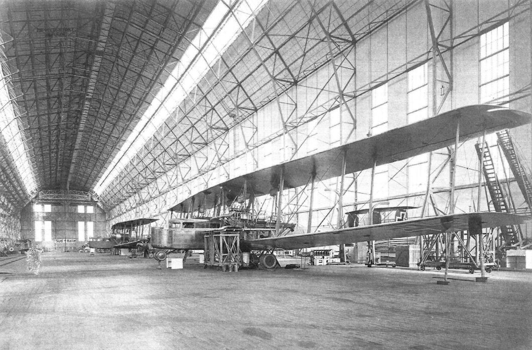
Staaken R.VI 30/16 being fitted with supercharger in the Staaken airship hangar. In the background is the Staaken R.XIV 43/17.
A Staaken R.VI R.30/16 under repair after an engine fire; Staaken R.XIV 43/17 is in the background without engines. Like other Staaken bombers, these types differed primarily by engine configuration; the R.VI had four engines in pusher/tractor configuration and the R.XIV added a fifth engine in the nose. (Michael Schmeelke)
A Staaken R.VI R.30/16 under repair after an engine fire; Staaken R.XIV 43/17 is in the background without engines. Like other Staaken bombers, these types differed primarily by engine configuration; the R.VI had four engines in pusher/tractor configuration and the R.XIV added a fifth engine in the nose. (Michael Schmeelke)

Staaken landing gear detail views.

Staaken R.VI tail skid.

Staaken R.VI photographed with its crew.

Front view of a Staaken R.VI on its field with onlookers giving scale to the aircraft. A parachute installation is visible at the side of the fuselage. (Peter M. Grosz collection/STDB)

Staaken R.VI on its field. Note the enlarged number of wheels used at airfields that are not reinforced. (Peter M. Grosz collection/STDB)

Front view of a Staaken R.VI on its field with onlookers giving scale to the aircraft. Note the standard number of wheels used with a reinforced runway. (Peter M. Grosz collection/STDB)

Staaken R.VI production aircraft from the R.27-R.29 batch. (Peter M. Grosz collection/STDB)
Front view of a Staaken R.VI on its field with Albatros D.V at right. (Peter M. Grosz collection/STDB)

Staaken R.VI bomber in night bomber camouflage runs up its engines. Camouflage is night 5-color printed canvas. Nose, roof, and fuselage bottom are not canvas and are painted. (Peter M. Grosz collection/STDB)

Staaken R.VI covered with dark, night camouflage and unpainted aluminum nacelles, running up its engines. (Peter M. Grosz collection/STDB)

A Staaken R.VI bomber undergoing maintenance. Note the camouflage pattern on the underside of the upper wing. (Peter M. Grosz collection/STDB)

Staaken R.VI bomber on its airfield. (Peter M. Grosz collection/STDB)

Staaken R.VI bombers on the factory airfield. Printed five-color night camouflage fabric was used to cover the fuselage. (Peter M. Grosz collection/STDB)

Staaken R.VI bombers on the factory airfield. Printed five-color night camouflage fabric was used to cover the fuselage. (Peter M. Grosz collection/STDB)

Staaken R.VI of the R.27-R.29 batch under construction (in an airship hall ???). (Peter M. Grosz collection/STDB)

Staaken R.VI production aircraft from the R.27-R.29 batch. (Peter M. Grosz collection/STDB)

Staaken R.VI bomber with crewmen. (Peter M. Grosz collection/STDB)

A Staaken R.VI production aircraft from the R.27-R.29 batch. (Peter M. Grosz collection/STDB)

A Staaken R.VI bomber on its airfield. It is covered with 5-color printed fabric. Note the small windows for the ventral gunner in the center fuselage and unpainted engine nacelles. (Peter M. Grosz collection/STDB)

Mechanics study the forward port engine of a Staaken R.VI bomber in its hangar. (Peter M. Grosz collection/STDB)

The large size of the Staakens required large airfields as illustrated here. (Peter M. Grosz collection/STDB)

Staaken R.VI bomber wearing night bomber camouflage in flight over the countryside. (Peter M. Grosz collection/ STDB)

Staaken R.VI bomber wearing night bomber camouflage in flight over the countryside. (Peter M. Grosz collection/ STDB)

Aerial view of the tail of the Staaken R.VI bomber. (Peter M. Grosz collection/STDB)

Views of the Staaken R.VI R.27, R.28, and R.29 aircraft. The in-flight photos were taken during an initial flight before camouflage was applied. (Peter M. Grosz collection/STDB)

Two mechanics in the starboard engine nacelle. (Peter M. Grosz collection/STDB)

Staaken R.VI bomber photographed inflight. (Peter M. Grosz collection/STDB)

Landing gear detail of a Staaken R.VI bomber. (Peter M. Grosz collection/STDB)

Detail view of an engine bed and oil cooler in a Staaken R.VI. (Peter M. Grosz collection/STDB)

Staaken R.VI R.26/16 radiator. (Peter M. Grosz collection/STDB)

View toward the tail of the fuselage interior of a Staaken R.VI bomber. The shadows of the 5-color night camouflage pattern on the exterior show on the inside of the fabric. (Peter M. Grosz collection/STDB)

Staaken R.VI under construction at the factory with 245 liter fuel tanks at left. (Peter M. Grosz collection/STDB)

Staaken R.VI final aerodynamically balanced tail assembly.

In flight photo of a copilot flying a Staaken R.VI bomber. (Peter M. Grosz collection/STDB)

Cockpit and radio position of R.25/16. (Peter M. Grosz collection/STDB)

Cockpit of Staaken R.VI R.26/16. (Peter M. Grosz collection/STDB)

Cockpit of Staaken R.VI.

Staaken inclinometer control panel.

Gyro inclinometer installed in Staaken bombers.

Staaken R.VI internal views showing fuel tanks and engineers station. (Peter M. Grosz collection/STDB)

Radio room of a Staaken R.VI. (Peter M. Grosz collection/STDB)

Two views of the wireless transmitter/ receiver station used in Staaken bombers.

Two views of the Bosch unit in the Staaken R-planes.

German magazine partial cutaway drawing of a Staaken R.VI. (Peter M. Grosz collection/STDB)

Fuel distribution in an R.VI with supercharger; only the R.30 had this installation.

Fuel distribution schematics for an R.VI with gravity tank.

Fuel distribution schematics for an R.VI with gravity tank.

Construction of the fuel tanks in Staaken bombers.

Schematics of Staaken R-plane construction


R.VI pilots' flight control console.


Structural details of the center of the front spar of the Staaken upper wing.

Drawing of a Staaken R.VI from a French intelligence report. (Peter M. Grosz collection/STDB)

Internal construction of the wings of the R.VI.

Internal construction of the nose of the R.VI.

Drawings of the Staaken R.VI showing the internal structure and fuel tanks. The fuel tanks were located over the center of gravity so the center of gravity could be maintained as the fuel was burned. The flight engineer was responsible to use the fuel from the tanks in such a way as to keep the center of gravity within limits.

Drawings of the Staaken R.VI.
Staaken Specifications
Type R.XIV R.XIVa R.XV
Engines 5x245 Hp Maybach Mb.IVa 5x245 Hp Maybach Mb.IVa 5x245 Hp Maybach Mb.IVa
Span 42.2 m (138' 5 1/2") 42.2 m (138'5 1/2") Similar to R.XIV
Chord (inner) 4.6 m (15' 1") - Similar to R.XIV
Chord (outer) 3.6 m (11' 10") - Similar to R.XIV
Length 22.5 m (73' 10") 22.5 m (73' 10") Similar to R.XIV
Height 6.3 m (20' 8") 6.3 m (20' 8") Similar to R.XIV
Tail span - - Similar to R.XIV
Wing Area 334 m2 (3,594 ft2) 332 m2 (3,572 ft2) Similar to R.XIV
Wt. Empty 10,350 kg (22,822 lb.) 10,000 kg (22,050 lb.) -
Wt. Fuel - - -
Wt. Payload - 5,000 kg (11,025 lb.) -
Wt. Loaded 14,450 kg (31,862 lb.) 14,250 kg (31,421 lb.) -
Max Speed 130 km/h (80.8 m/h) 135 km/h (83.9 m/h) -
Climbing Spd 100 km/h (62.1 m/h) 95 km/h (59 m/h) -
Climb 1,000 m - 7 minutes -
Climb 3,000 m 70 minutes (with load) 45 minutes -
Ceiling 3,700 m 4,500 m -
Range (1,000 kg bombs) 1,300 km (808 miles) 1,300 km (808 miles) -
Staaken R.VI 30/16 being fitted with supercharger in the Staaken airship hangar. In the background is the Staaken R.XIV 43/17.
A Staaken R.VI R.30/16 under repair after an engine fire; Staaken R.XIV 43/17 is in the background without engines. Like other Staaken bombers, these types differed primarily by engine configuration; the R.VI had four engines in pusher/tractor configuration and the R.XIV added a fifth engine in the nose. (Michael Schmeelke)
A Staaken R.VI R.30/16 under repair after an engine fire; Staaken R.XIV 43/17 is in the background without engines. Like other Staaken bombers, these types differed primarily by engine configuration; the R.VI had four engines in pusher/tractor configuration and the R.XIV added a fifth engine in the nose. (Michael Schmeelke)
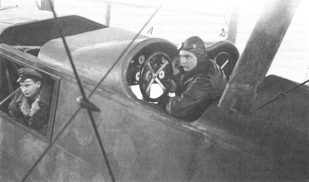
The cockpit of a Staaken R.XIVa showing its night camouflage. (Piotr Mrozowski collection)
Staaken Specifications
Type R.VII R.VIII & R.IX 8307
Engines 2x160 Hp Mercedes D.III 4x220 Hp Benz Bz.IV 8x260 Hp Mercedes D.IVa OR 8x245 Hp Maybach Mb.IVa 4x530 Hp Benz Bz.VI
Span 42.2 m (138'5 1/2") 55 m (180'5") -
Length 22.1 m (72' 6") 30 m (98'5") -
Height 6.8 m (22' 3 1/2") 8.8 m (28' 10") -
Wing Area 332 m2 (3,572 ft2) - -
Wt. Empty 8,923 kg (19,675 lb.) - -
Wt. Fuel 2,140 kg (4,719 lb.) - -
Wt. Payload 1,890 kg (4,167 lb.) - -
Wt. Loaded 12,953 kg (28,561 lb.) - -
Max Speed 130 km/h (80.8 mph) - -
Climb 1,000 m 12 minutes - -
Climb 2,000 m 25.5 minutes - -
Climb 3,000 m 50 minutes - -
Ceiling 3,850 m - -
The Staaken R.VIII, R.IX, and 8307 were unbuilt projects. The 8307 was a seaplane for the Navy.
Staaken Specifications
Type R.XVI L 8301 & 8303
Engines 2x500 Hp Benz Bz.VI 2x220 Hp Benz Bz.FV 4x260 Hp Mercedes D.IVa 4x260 Hp Mercedes D.IVa
Span 42.2 m (138' 5 1/2") 42.2 m (138' 5 1/2") 42.2 m (138'5 1/2")
Chord (max.) - 4.53 m( 14' 10") -
Gap (max.) - 4.55 m (14' 11") -
Length 22.5 m (73' 10") 22.2 m (72' 10") 21 m (68' 10 1/2")
Height 6.5 m (21'4") 7.38 m (24' 2 1/2") 6.8 m (22'3 1/2")
Wing Area 340 m2 (3,658 ft2) 360 m2 (3,874 ft2) 340.5 m2 (3,663 ft2)
Wt. Empty 10,400 kg (22,932 lb.) 8,400 kg (18,522 lb.) 9,000 kg (19,845 lb.)
Wt. Fuel - 2,445 kg (5,391 lb.) -
Wt. Loaded 14,650 kg (32,303 lb.) 11,800 kg (26,019 lb.) 12,500 kg (27,563 lb.)
Max Speed 130 km/h (80.8 m/h) 125 km/h (77.7 m/h) 130 km/h (80.8 m/h)
Climb 1,000 m - 23.7 minutes (full load) -
Climb 1,780 m - 60 minutes -
Ceiling 3,710 m 2,500 m -
Duration - 10 hours -
The Staaken L & 8301/8303 were naval floatplanes derived from the R.VI. The 8301 & 8303 could climb to 3,000 m in 54 minutes.
Staaken Specifications
Type E.4/20
Engines 4x245 Hp Maybach Mb.IVa
Span 31.0 m (101'8")
Length 16.5 m (54' 1")
Height 4.5 m (14'9")
Wing Area 106 m2 (1,141 ft2)
Wt. Empty 6,072 kg (13,389 lb.)
Wt. Loaded 8,500 kg (18,743 lb.)
Max Speed 225 km/h (139.8 m/h)
All-metal, 4-engine transport monoplane. Built starting in May 1919, completed 30 Sept. 1920.