В.Кондратьев Самолеты первой мировой войны
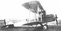
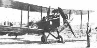
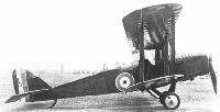
ДЕ ХЭВИЛЛЕНД DH.4 / DE HAVILLAND DH.4
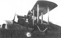
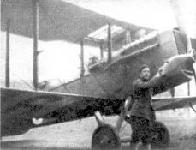
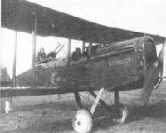
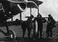
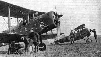
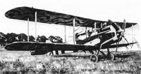
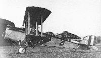
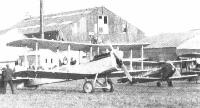
Цельнодеревянный двухстоечный биплан с полотняной обшивкой. Разработан известным английским летчиком и авиаконструктором, владельцем фирмы Эйркрафт Мэньюфэктуринг Компани Лимитед (Эйрко) сэром Джефри Де Хэвиллендом. В августе 1916 года самолет под управлением своего создателя совершил первый полет. Летные данные были признаны обнадеживающими, и DH.4 рекомендовали к принятию на вооружение с заменой 160-сильного мотора "Бердмор" на более мощный Сиддли "Пума" или Роллс-Ройс "Игл III".
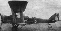
В январе 1917-го первые серийные аппараты вышли из цехов завода фирмы Эйрко в Хендоне. А в марте первый дивизион, оснащенный DH.4 прибыл на, западный фронт. До конца 1918 года в Великобритании построено 1449 экземпляров машины. Еще около 2500 выпущено по лицензии в США. На американские DH.4 ставили местные двигатели "Либерти". В 1920-21 годах московский завод ГАЗ №1 (бывший "Дукс") построил по английским чертежам 20 самолетов с итальянскими двигателями "Фиат" A-12 в 240 л.с.
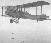
DH.4 хорошо проявил себя в качестве фронтового бомбардировщика и фоторазведчика. Высокая скорость и большой потолок делали его малоуязвимым для зенитного огня и вражеских истребителей. Характеристики машины, особенно скороподъёмность, еще более улучшились с установкой форсированного мотора "Игл" VIII. Около 70 "Де Хэвиллендов" с этими двигателями англичане использовали в качестве ночных истребителей для отражения налетов "Цеппелинов" на Британские острова. Единственным недостатком самолета считались далеко разнесенные по фюзеляжу кабины пилота и летнаба, из-за чего было невозможно взаимодействие между членами экипажа в полете.
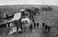
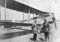
DH.4 с успехом применялся до окончания первой мировой войны на всех фронтах, где воевали английские Королевские ВВС, а также в составе американского экспедиционного корпуса в Европе. По окончании боевых действий несколько десятков машин закупили Греция, Испания, Бельгия и Япония. Отдельные экземпляры служили до середины двадцатых годов в различных гражданских авиакомпаниях, перевозя пассажиров и почту. Кроме того самолет состоял на вооружении белых армий Деникина и Врангеля, участвуя в боях на Волге и на юге России. В 1919 году 10 машин с двигателями "Либерти" и 2 с "Иглами" были захвачены красными.
ДВИГАТЕЛЬ
Сиддли "Пума" (230 л.с.) или Роллс-Ройс "Игл"III (270 л.с.) или "Игл"VIII (375 л.с.) или "Либерти" (400 л.с.).
ВООРУЖЕНИЕ
1 синхр. "Виккерс" и 1-2 турельных "Льюиса", до 210 кг.бомб. Американцы вместо "Виккерса" устанавливали 2 "Мерлина".
Показать полностью
А.Шепс Самолеты Первой мировой войны. Страны Антанты
Де Хевилленд D.H.4 1917 г.
Боевые действия на Западном фронте выявили острую потребность в разведчике и легком бомбардировщике, способном не только нести значительную бомбовую нагрузку, но и противостоять атакам вражеских истребителей. К тому же, для решения оперативных задач возникла потребность в машинах, способных действовать в группах. Существующие машины, переоборудованные из учебных самолетов и разведчиков, не имели необходимых тактико-технических данных. Кроме того, они несли большие потери, потому что не имели достаточного вооружения.
Построенный к началу 1917 года фирмой "Де Хевилленд Лимитед" двухместный двухстоечный биплан классической схемы отвечал всем требованиям военных и был сразу же запущен в серию под маркой D.H.4.
Самолет цельнодеревянной конструкции с каркасом из профилированных брусков и растяжками из стальной ленты. Задняя часть фюзеляжа обтянута полотном, а передняя обшита 3-4-мм фанерой. Капот двигателя выполнялся из алюминиевых листьев. Двигатель крепился к клепанной металлической раме. За двигателем размещалась кабина пилота, за ней - топливный бак, а за ним - кабина наблюдателя с турельной установкой пулемета "Льюис".
Крылья двухлонжеронные, из профилированного в форме двутавра бруса (у P-1 - коробчатые на консолях) с нервюрами из бруска и фанеры, обшитые полотном, пропитываемом затем лаком. Стойки деревянные с растяжками из стальной ленты. Элероны на верхнем и нижнем крыле. Стабилизатор обычной конструкции с изменяемым в полете углом установки. Вертикальное оперение обычной конструкции с килем перед рулем поворота. Управление рулями тросовое, от ручки управления и педалей. Шасси обычной конструкции с каркасом из соснового бруса, сквозной осью и резиновой амортизацией.
Двигатели различались в зависимости от модификации, но в основном это были либо рядные, либо V-образные жидкостного охлаждения, 8- и 12-цилиндровые. Радиаторы либо сотовые на передней кромке центроплана, либо трубчатые по бокам фюзеляжа, либо сотовые лобовые, устанавливаемые перед двигателем. Винт в основном четырехлопастной с небольшим коком.
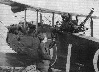
Стрелковое вооружение самолета состояло из синхронного пулемета 7,69-мм "Виккерс" и турельного 7,62-мм "Льюис". Под центропланом подвешивались бомбы калибра от 5,4 до 56 кг общей массой до 227 кг. В кабине наблюдателя устанавливался бомбовый прицел Дорана Ларайя.
Модификации
D.H.4a - первоначальный вариант с 12-цилиндровым V-образным двигателем жидкостного охлаждения в 253 л. с. и лобовым сотовым прямоугольным радиатором. Двигатель фирмы "Роллс-Ройс".
D.H.4b - развитие предыдущего, с двигателем Роллс-Ройс "Игл" мощностью 360 л. с. с лобовым радиатором овальной формы. Летные данные значительно улучшились.
D.H.4 "Сиддли-Пума" - было выпущено несколько машин, из-за нехватки двигателей "Роллс-Ройс" с рядными двигателями "Сиддли-Пума" (220л. с.).
D.H.4 "Либерти" - в США по лицензии несколько фирм строили самолеты D.H.4 для авиации США с американским 12-цилиндровым V-образным двигателем жидкостного охлаждения "Либерти" (400 л. с.).
DH-4 "Дукс" - в конце 1917 года российский завод "Дукс" получил чертежи D.H.4 и начал освоение этой машины. Подготовка производства продолжалась и в годы Гражданской войны. С 1921 года самолет стал выпускаться небольшими сериями с различными двигателями под марками Р-I и Р-II. Ставились разные двигатели: "Фиат-12" (240 л. с.), "Сиддли-Пума" (220 л. с.) или "Даймлер" (260 л. с.). На одном самолете поставили стойки из стальных каплевидных труб, на другом - трофейный двигатель "Майбах" (260 л. с.). Всего построено около 20 машин, причем все они имели либо трубчатые боковые радиаторы, либо сотовые над центропланом.
ЛЕТНО-ТЕХНИЧЕСКИЕ ХАРАКТЕРИСТИКИ
D.H.4 D.H.4a D.H.4b D.H.4 "Фиат"
1917г 1917г 1921г
Размах, м 12,92 12,92 12,95 13,04
Длина, м 9,35 9,35 9,05 9,40
Высота, м 3,05 3,05 3,05
Площадь крыла, кв.м 40,30 40,30 39,70 39,50
Сухой вес, кг 1082 1082 1050 1160
Взлетный вес, кг 1576 1503 1515 1585
Двигатель Игл III "Роллс-Ройс" "Фиат" А12
мощность, л. с. 253 360 240
Скорость максимальная, км/ч 188 188 193 188
Время набора высоты, м/мин 1800/7
Дальность полета, км 560 600 600
Потолок,м 4870 4870 6000 6200
Экипаж, чел. 2 2 2
Вооружение 2 пулемета 2 пулемета 2 пулемета 2 пулемета
227кг бомб 254кг бомб 350 кг бомб
Показать полностью
В.Шавров История конструкций самолетов в СССР до 1938 г.
Самолет DH-4 с двигателем "Фиат" A-12 в 240 л. с. Это был двухместный биплан деревянной конструкции с полотняной обтяжкой крыльев. Кабина летчика размещалась под центропланом, за ней был бензобак и далее кабина летнаба (в последующем типе DH-9 под центропланом находился бензобак, а за ним были обе кабины- размещение более совершенное). Расчалки коробки крыльев были тросовые. Радиаторы - трубчатые вертикальные - располагались по бокам фюзеляжа или же один сотовый на передней кромке центроплана. Общее выполнение было несколько грубым. Самолеты выпускались заводом ГАЗ № 1 (бывший "Дукс"), в 1920-1921 гг. было сделано 20 таких самолетов. На одном самолете были поставлены стойки - стальные трубы каплевидного сечения (в 1923 г.), на другом - двигатель "Майбах" в 260 л. с., но особых преимуществ это не дало. В том же году В. В. Калинин и В. Л. Моисеенко поставили на одном самолете крылья более толстого профиля. Испытания этого самолета, проведенные в начале 1924 г., показали некоторое улучшение летных качеств, но по соображениям серийного производства измененные крылья приняты не были.
Самолет|| DH-4/DH-4/DH-4
Год выпуска||1917/1918/1921
Двигатель , марка||//
мощность, л. с.||360/400/240
Длина самолета, м||9,05/9,2/9,4
Размах крыла, м||12,95/12,95/13,04
Площадь крыла, м2||39,7/40,5/39,5
Масса пустого, кг||1050/1290/1160
Масса топлива+ масла, кг||231/225/175+25
Масса полной нагрузки, кг||465/510/425
Полетная масса, кг||1515/1800/1585
Удельная нагрузка на крыло, кг/м2||38,2/44,5/40,1
Удельная нагрузка на мощность, кг/лс||4,2/4,5/6,5
Весовая отдача,%||30,7/28,4/26,8
Скорость максимальная у земли, км/ч||193/188/151
Скорость посадочная, км/ч||?/?/80
Время набора высоты 1000м, мин||?/?/8
Время набора высоты 2000м, мин||8/8/18
Время набора высоты 3000м, мин||14/14/34
Время набора высоты 4000м, мин||?/?/62
Потолок практический, м||6000/6200/4000
Продолжительность полета, ч.||3,5/3,5/3
Дальность полета, км||600/600/450
Показать полностью
A.Jackson De Havilland Aircraft since 1909 (Putnam)
De Havilland D.H.4
The Airco D.H.4 day bomber, the prototype of which was numbered 3696 and first flew at Hendon in August 1916, was without question one of the outstanding aeroplanes of the First World War. Its fabric covered, wire braced, spruce and ash structure was typical of the day but the front fuselage, housing the cockpits and main fuel tanks, was strengthened with a plywood covering. Mainplanes and tailplane followed the usual two spar layout but the spars were lightened by spindling between the ribs and the tailplane was fitted with variable incidence gear. Rubber cord suspension was used in the undercarriage (two 6 ft. 9 in. lengths wound into nine turns for each wheel), and the fin and rudder conformed to the de Havilland family shape first used on the D.H.3. Standard armament consisted of one synchronised forward firing Vickers gun mounted on top of the fuselage, single or twin Lewis guns on a Scarff ring for the observer, and two 230 lb. and four 112 lb. bombs were carried in racks under the fuselage and wings respectively.
The prototype was fitted with a 230 h.p. B.H.P. six cylinder watercooled engine and was unique in having rear centre section struts which raked sharply forward. Production D.H.4s had the rear struts shortened and made parallel to the front and were powered by a variety of engines, including the 200 h.p. R.A.F. 3A, 230 h.p. Siddeley Puma, 250 h.p. Rolls-Royce III and 260 h.p. Fiat. Pilots were warned not to damage the airscrew by taking off with the tail too high, so that when more powerful engines such as the 375 h.p. Rolls-Royce Eagle VIII were developed and larger airscrews were needed, it was necessary to fit a taller undercarriage and this eventually became standard on all D.H.4s. The incidence was also increased to shorten the landing run. All these engines were cooled by frontal radiators except the Fiat, first installed in A7532, the radiator for which was between the front undercarriage legs, permitting the use of close fitting engine cowlings in the manner of the later D.H.9. In addition to the modified undercarriage, late production D.H.4s also had the rear Scarff ring raised to improve the field of fire and the rear decking was made fiat. Orders were placed with Airco and six sub-contractors for some 1,700 D. H.4s, of which 1,449 were actually delivered.
Pilots who flew the D.H.4 were unanimous in praise of its fine handling qualities, wide speed range and a performance which made it almost immune from interception. No previous aeroplane had had so wide a speed range (45-143 m.p.h. On the Eagle VIII version) and pilots' notes emphasised its slow speed docility, recommending that the approach be made at 60 and the touch down at 50 m.p.h. Operating at heights above 15,000 ft. the D.H.4 could outfly contemporary single seat fighters but if caught was usually an easy victim because the cockpits were so far apart that in the noise of battle Gosport tubes were useless as a means of coordinating defence and the aircraft went down in flames when bullets punctured the 60 gallon fuel tank between the seats. Late in 1917 fire hazards were much reduced when the pressurised fuel system was replaced by two wind driven pumps on top of the fuselage behind the pilot.
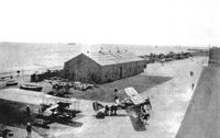
The first D.H.4s in France, delivered by air to No. 55 Squadron on March 6, 1917, were first used operationally at Valenciennes on April 6. As an R.A.F. Squadron at the end of the war, it bombed munitions factories at Frankfurt, Mannheim and Stuttgart but French and Belgian based D.H.4s were not entirely employed as day bombers but also made high level photographic reconnaissance flights, fighter sweeps and anti-Zeppelin and submarine patrols. The majority of naval D.H.4s were among 150 built under sub-contract by the Westland Aircraft Works. They were Eagle powered and fitted with twin, instead of single front guns and also a raised Scarff ring mounting for the rear gunner, but increases in weight and parasitic drag somewhat impaired their performance. The first D.H.4 to be built at Yeovil was flight tested by B. C. Hucks in April 1917 and delivered in France the next morning. Coastal patrols were also undertaken by R.N.A.S. Squadrons and at least one D.H.4 was experimentally fitted with twin floats for this task. No. 202 Squadron also took a complete set of oblique and vertical photographs of Zeebrugge in preparation for the historic raid of April 22-23, 1918 during which the Mole was bombed with great daring by Wg. Cdr. Fellowes flying a D.H.4. To No. 217 Squadron fell the honour of sinking the German submarine U.B.12 on August 12, 1918. R.N.A.S., Great Yarmouth, was armed with D.H.4s, one of which was ditched in the North Sea on September 5, 1917 after an unsuccessful attack on the Zeppelin L.44, the crew being picked up by flying boat. On August 5, 1918 however, A8032 piloted by Major Egbert Cadbury shot down L.70 when 41 miles N.E. of base, from a height of over 16,000 ft. The Home Defence D.H.4s were operated far over the North Sea and efforts were made at the M.A.E.E., Isle of Grain, to equip them with flotation gear or as an alternative, hydrovanes and wing tip floats for use after the undercarriage was jettisoned. These devices were developed and test flown by Harry Busteed using D.H.4s A 7457 and D1769. The latter was also used for trailing mine experiments and hydrovanes were also fitted to an American built DH-4 at McCook Field, Dayton, Ohio. Two D.H.4s, one of which was numbered A2168, were fitted with H pounder Coventry Ordnance Works quick firing anti-Zeppelin guns. In 1917-18 the type was used overseas in small numbers as shown on page 67, while in the period 1919-21 many went as Imperial Gifts to assist the formation of air forces in Canada (12 aircraft) and South Africa (e.g. serials 26 and 401). Airco-built D.H.4s A7893 and A7929, taken to New Zealand in 1919 by Col. A. V. Bettington. were stationed at Sockburn and A7893, piloted by Capt. T. Wilkes and L. M. Isitt was the first aircraft to fly over Mt. Cook.
As an engine test bed the D.H.4 made a major contribution to Allied technical superiority and among the several experimental installations were those of the 300 h.p. Renault 12Fe in A2148, the 400 h.p. Sunbeam Matabele in A8083, the 353 h.p. Rolls-Royce G and the Ricardo-Halford inverted supercharged engine. One of the new American 400 h.p. Liberty 12 engines was fitted into a British built D.H.4 delivered at McCook Field in August 1917. It first flew with the Liberty on October 29th of that year and heralded the mass production of the D.H.4 in America. By the Armistice 3,227 had been constructed, 1,885 of which were shipped to France and by the end of 1918 the total of American built DH-4s had risen to 4,587, or more than three times the British production of 1,449. Eventually, the three American contractors delivered 4,846 examples of the DH-4, but after the war they were disposed of in considerable numbers to the Nicaraguan and other Latin American army air services.
Financial depression virtually stopped the procurement of new American aircraft during the postwar years but maintenance funds permitted a considerable rebuilding programme. This gave rise to over 60 DH-4 variants, many of which remained on the active list for nearly a decade. The majority of such variants received an American-style hyphenated model number, commencing with DH-4A, applied to the single Dayton-Wright DH-4 which was fitted in July 1918 with an improved fuel system by the Engineering Division of the Army's Department of Aircraft Production. This aircraft should not be confused with the British cabin conversion designated D.H.4A. In October 1918, more extensive modifications by the Engineering Division produced the DH-4B in which the pilot's cockpit was moved back next to that of the gunner. One DH-4B, piloted by Lt. Maynard, won the New York-Toronto Aerial Derby on August 25, 1919 in a flying time of 7 hours 45 minutes. The total of such conversions made in 1918-24 reached 1,540 when the two final rebuilds were made by the de Havilland Aircraft Co. Ltd. to the order of Maj. Davidson for the use of Naval and Military Attaches of the U.S. Embassy in London. These aircraft, c/n 138 and 139, were test flown by Hubert Broad in August 1926 and based at Kenley and Stag Lane respectively in full U.S. military markings until replaced by a D.H.60 Moth in 1927.
American conversions fell into two main categories - specialized versions for military purposes, the surviving designations for which are listed in an accompanying table, and experimental conversions of the early DH-4B, mainly as engine testbeds or trial installations aircraft. Military models included the DH-4B-2 trainer, sometimes known as the Blue Bird, the DH-4B-5 two passenger Honeymoon cabin transport devised by the Engineering Division of the Bureau of Aeronautics, and ambulance versions for one or two stretchers. Two of the last named, U.S. Marine serials A5811 and A5883, were used in 1922 in the island of Haiti, starting point of the longest flight in U.S. history up to that time, made in 1924 by two U.S. Army DH-4Bs which successfully covered the 10,953 miles to San Francisco and back.
DH-4 variants remained in military service with the U.S. Army, Navy and Marines until 1929, one DH-4B-3 being re-engined with a Packard 2A-1500 by the U.S. Navy at Quantico in 1926, but the last of the major variants had already appeared in 1924. They were built for the Corps Observation role, three by the Boeing company and one by Atlantic. The Boeings were ungainly sesquiplanes using steel DH-4M-1 fuselages and thick section wings of new design. The first, designated XCO-7, became the XCO-7A when fitted with a wide track undercarriage but crashed and was replaced by the XCO-7B, a similar machine powered by a 420 h.p. Liberty V-1410 experimental inverted engine. These prototypes scarcely resembled the DH-4B at all but the origins of the remaining Corps Observation conversion, XCO-8, could hardly be mistaken, being a reproduction of an undesignated conversion made in 1922 by the Gallaudet Aircraft Corporation which fitted a standard Liberty powered DH-4B with the mainplanes and N type interplane struts from a Loening COA-1 amphibian. The true XCO-8 was an exactly similar conversion made two years later by the Atlantic company.
Steel tube fuselages were built by the Boeing and Atlantic companies in 1920-25 to extend the useful lives of these veterans under the designations DH-4M, DH-4M-1 and DH-4M-2, 186 of which were by Boeing and at least 135 by Atlantic. Considerable interest was aroused when two reworked and specially modified DH-4s took off from Rockwell Field, San Diego, California on June 27, 1923 to conduct one of the first flight refuelling experiments. Lts. Lowell Smith and Paul Richter remained airborne for 6 1/2 hours, during which time they were refuelled twice by hose from the DH-4 flown by Lts. Hine and Seifert. After minor adjustments they kept aloft for 37 1/4 hours on August 27-28th and landed only when fog prevented further contact with the tanker. On December 13, 1923 a DH-4 with supercharged Liberty, piloted by Lt H. Harris and carrying a passenger, climbed to an altitude of 27,000 ft. over McCook Field, increased later to 30,500 ft., reached in 69 minutes in a special DH-4B, N.A.C.A. 8, fitted with a Roots type supercharger behind the engine. In 1927 a DH-4M-2, N.A.C.A. 25, with Model II Roots blower, reached 26,500 ft. in 51 minutes using camera recorded automatic observer equipment in an enclosed rear cockpit.
SPECIFICATION AND DATA
Manufacturers:
The Aircraft Manufacturing Co. Ltd., Hendon, London, N.W.9
F. W. Berwick and Co. Ltd., Park Royal, London, N.W.10
Glendower Aircraft Co. Ltd., 54 Sussex Place, South Kensington, London, S.W.7
Palladium Autocars Ltd., Felsham Road, Putney, London, S.W.15
The Vulcan Motor and Engineering Co. (1906) Ltd., Southport, Lanes.
Waring and Gillow Ltd., Cambridge Road, Hammersmith, London, W.6
Westland Aircraft Works, Yeovil, Somerset
SABCA, Haren Airport, Brussels, Belgium (15 built in 1926 for Belgian Air Force)
Atlantic Aircraft Corporation, Teterboro, New Jersey, U.S.A.
Boeing Airplane Company, Seattle, Washington, U.S.A.
The Dayton-Wright Airplane Co., Dayton, Ohio, U.S.A. (3,106 built)
The Fisher Body Corporation, U.S.A. (1,600 built)
Standard Aircraft Corporation, Elizabeth, New Jersey, U.S.A. (140 built)
Power Plants:
One 200 h.p. R.A.F. 3A
One 230 h.p. B.H.P.
One 230 h.p. Siddeley Puma
One 250 h.p. Rolls-Royce Mk. III or M k. IV
One 260 h.p. Fiat
One 275 h.p. Rolls-Royce Eagle VI
*One 300 h.p. Renault 12Fe
*One 300 h.p. Wright H
*One 300 h.p. Packard 1A-1116 o r 1A-1237
*One 320 h.p. Armstrong Siddeley Jaguar I
One 325 h.p. Rolls-Royce Eagle VII
*One 353 h.p. Rolls-Royce G
One 375 h.p. Rolls-Royce Eagle VIII
*One Ricardo-Halford supercharged engine
One 400 h.p. Liberty 12
*One 400 h.p. Sunbeam Matabele
*One 420 h.p. Liberty V-1410
One 435 h.p. Liberty 12A
*One 435 h.p. Curtiss D-12
*One 525 h.p. Packard 2A-1500
* Experimental installation
Dimensions, Weights and Performances:
(a) British
B.H.P. Puma Rolls III Eagle VIII RAF. 3A Fiat Liberty 12
Span 42 ft. 4 5/8 in. 42 ft. 4 5/8 in. 42 ft. 4 5/8 in. 42 ft. 4 5/8 in. 42 ft, 4 5/8 in. 42 ft. 4 5/8 in. 42 ft. 6 in.
Length 30 ft. 8 in. 30 ft. 8 in. 30 ft. 8 in. 30 ft. 8 in. 29 ft. 8 in. 29 ft. 8 in. 30 ft. 6 in.
Height 10 ft. 1 in. 10 ft. 1 in. 10 ft. 5 in . 11ft. 0in, 10 ft. 5 in. 10 ft. 5 in. 10ft. 3 5/8 in.
Wing area 434 sq. ft. 434 sq. ft. 434 sq. ft. 434 sq. ft. 434 sq. ft. 434 sq. ft. 440 sq. ft.
Tare weight 2,197 lb. 2,230 lb. 2,303 lb. 2,387 lb. 2,304 lb. 2,306 lb. 2,391 lb.
All-up weight 3,386 lb. 3,344 lb. 3,313 lb. 3,472 lb. 3,340 lb. 3.360 lb. 4,297 lb.
Maximum speed 108 m.p.h. 106 m.p.h. 119 m.p.h. 143 m.p.h. 122 m.p.h. 114 m.p.h. 124 m.p.h.
Initial climb 700 ft./min. 1,000 ft./min. 925 ft./min. 1,350 ft./min. 800 ft./min. 1,000 ft./min.
Ceiling 17,500 ft. 17,400 ft. 16,000 ft. 22,000 ft. 18,500 ft. 17,000 ft. 17,500 ft.
Endurance 4 1/2 hours 4 1/2 hours 3 1/2 hours 3 3/4 hours 4 hours 4 1/2 hours 3 hours
(b) American
DH-4B DH-4M-1 DH-4M-2 XCO-7 XCO-7A XCO-7B XCO-8
Engine Liberty 12A Liberty 12A Liberty 12A Liberty 12A Liberty 12A Liberty V-1410 Liberty 12A
Span 42 ft. 5 1/2 in. 42ft. 5 1/2 in. 42 ft. 5 1/2 in. 45 ft. 0 in. 45 ft. 0 in. 45 ft. 0 in. 45 ft. 0 in.
Length 29ft. 11 in. 29 ft. 11 in. 29ft. 11 in. 30ft. 4 in. 30ft. 4 in. 30ft. 11 in. 30ft. 0in.
All-up weight 4,600 lb. 4,595 lb. 4,595 lb. 4,798 lb. 4,800 lb. 4,652 lb. 4.680 lb.
Maximum speed 124 m.p.h. 118 m.p.h. 118 m.p.h. 130 m.p.h. 122 m.p.h. 130 m.p.h.
De Havilland D.H.4 (Civil)
Several million pounds worth of war surplus aircraft, including hundreds of D.H.4s, the majority brand new from the Airco and Waring and Gillow factories, were acquired by Handley Page Ltd. in 1919-20 and later reconditioned by the Aircraft Disposal Co. Ltd. at Croydon to become the postwar equipment of the air forces of Spain (14 aircraft), Belgium, Greece, Japan and other small nations. With few exceptions these were powered by the 375 h.p. Rolls-Royce Eagle VIII engine and those for Spain and Belgium were flown out in the autumn of 1921 under temporary civil marks by many well known pilots of the day, including F. T. Courtney, H. Shaw, E. D. Hearne, F. J. Ortweiler, C. D. Barnard, E. L. Foot and Norman Macmillan. In Spain the D.H.4 formed the main equipment of the Air Force training establishment at Cuatros Vientos and was used extensively in the Moroccan War.
Two Eagle powered D.H.4s were also used in a purely civil capacity on the Continental services of Aircraft Transport and Travel Ltd. late in 1919 as temporary crash replacements and two others were shipped to Australia by C. J. de Garis and there fitted with cockpits for two passengers behind the pilot. One of them, F2691/G-AUCM was erected and test flown at Glenroy on November 27, 1920 and piloted by F. S. Briggs with the owner as passenger, arrived at Perth on December 2nd after making the first Melbourne-Perth flight in two days. A week later it made the first Perth-Sydney flight, also in two days, and on January 16, 1921 became the first aircraft to fly from Brisbane to Melbourne in one day. Again piloted by F. S. Briggs it left Melbourne on September 9, 1921 to survey the route of the proposed North-South railway and covered 3,000 miles in exactly one month, becoming the first aircraft ever to land at Alice Springs. From August 1924 it carried mail on the Adelaide-Sydney service of Australian Aerial Services Ltd. with the name "Scrub Bird" and was still flying miners and supplies between Port Moresby and Lae, New Guinea for Bulolo Goldfields Ltd. in 1927.
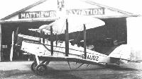
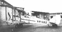
C. J. de Garis sold the other D.H.4, F2682/G-AUBZ to R. J. P. Parer who flew it to victory in the first Australian Aerial Derby on December 28, 1920 at 142 m.p.h. It was then used for joyriding and other pioneering work until delivered to QANTAS at Longreach by rail on August 12, 1922. In the last two months of the year it covered over 5,000 air miles, mainly on the Charleville-Cloncurry mail service but was extensively damaged when it struck telephone wires while landing at Gilford Park station, south west of Longreach, on June 6, 1923. During repairs the two open passenger cockpits were roofed over to make an open-sided cabin and it first flew in this form in May 1924. It opened the extension service between Cloncurry and Camooweal on February 7,1925 piloted by Capt. L. J. Brain but, when ousted by the new D.H.50s at the end of 1927, was sold to Matthews Aviation Ltd. at Essendon Aerodrome, Melbourne where the fuselage was modified for joyriding with no less than four separate passenger cockpits behind the pilot. At this stage it was named "Cock Bird" on the fin but in 1930 it returned to taxi work with a full D.H.4A-style cabin with sliding windows as "Spirit of Melbourne". It was last in service with Pioneer Air Services who acquired it in September 1934.
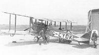
In Canada, all 12 Imperial Gift D.H.4s were equipped with air to ground W/T sets for use on forestry patrol work by the Air Board Civil Operations Branch and in 1921 one of these aircraft made the first recorded geological reconnaissance flight piloted by F/Lt. A. W. Carter. From August 1920 their pilots spotted hundreds of forest fires and helped save millions of dollars worth of timber, operating mainly from an airstrip at High River, Alberta where the D.H.4's performance alone could combat wind ridden skies near the Rockies. Special skis were designed for winter flying and as late as 1924 these veterans continued to give photographic coverage of the district but by that time showed such deterioration that they were permanently grounded at the end of the season. The one exception, G-CYDM, still airworthy in 1927, was reworked to D.H.4B standard with underslung radiator and observation panels in the lower wing roots.
The D.H.4's greatest contribution to the embryo air transport industry however, was made in Europe by four machines supplied by Handley Page Ltd. to the Belgian concern Syndicat National pour l'Etude des Transports Aeriens (SNETA). In company with a number of D.H.9s, they ran spasmodically on the Brussels-London, Brussels-Paris and Brussels-Amsterdam services in 1920-21, and although their normal London terminal was Croydon, many flights terminated at Cricklewood for convenience of servicing. After the departure to Brussels of D.H.4 O-BABI on January 15, 1921, Cricklewood was used no more and the D.H.4's commercial life ended soon afterwards in two major crashes and the destruction of most of the SNETA fleet in a disastrous hangar fire at Brussels on September 27, 1921. An accompanying table lists all the civil D.H.4s for which records still exist.
Apart from two machines employed by Aircraft Transport and Travel Ltd. as temporary replacements for crashed D.H.4As, the standard D.H.4 saw little civilian service in England. On June 21, 1919 however, Marcus D. Manton came third at an average speed of 117-39 m.p.h. in the Aerial Derby at Hendon in K-142, a new aircraft with Rolls-Royce Eagle VIII, specially demilitarised by the Aircraft Manufacturing Co. Ltd. It competed against a 'one-ofF racing version registered K-141 and designated D.H.4R to signify D.H.4 Racer. This monster was built in ten days by an enthusiastic team led by F. T. Hearle who fitted a 450 h.p. Napier Lion with chin radiator, clipped the lower mainplane at the first bay and braced the overhanging portion of the upper wing by slanting struts. Without stagger and with the rear cockpit faired over, it was scarcely recognisable as a D.H.4 derivative but Airco test pilot Capt. Gerald Gathergood flew it twice round London in 1 hour 2 minutes and set up a British closed circuit record of 129-3 m.p.h. This was indeed a creditable day's flying by two machines which had left the ground for the first time only that morning! The one other British civil example was G-EAMU acquired by the shipping firm of S. Instone and Co. Ltd., primarily for the fast carriage of ship's papers but also accommodating two passengers in the open rear cockpit. With Capt. F. L. Barnard as pilot and appropriately named "City of Cardiff', it emulated the Aerial Derby machines by making its first flight on the morning of October 13, 1919, a return flight to the Welsh capital in the afternoon and its maiden trip to Paris the next day. During 1920 several trips were made to Paris, Brussels, Nice, and on one occasion, to Prague.
In America DH-4s with Liberty 12 motors went into regular service with the United States Postal Department on August 12, 1918 and from June 1919 onwards a considerable number of DH-4Bs and DH-4Ms were converted for the carriage of 400 lb. of mail in a watertight compartment that had once been the front cockpit. The aircraft was thereafter flown from the rear as a single seater. In addition, thirty machines were reconstructed by the Lowe, Willard and Fowler Engineering Company to have increased span, two 200 h.p. Hall-Scott L-6 watercooled engines outboard and a large mail compartment in the nose. One normal DH-4B, No. 299, was given a special fuselage having a cargo hold for 800 lb. of mail between the undercarriage legs. New wings of modified section were built by the Aeromarine Company and in 1922 No. 299 carried a record load of 1,032 lb. from New York to Washington at its economical cruising speed of 68 m.p.h. Other important and unusual DH-4 mailplanes included one fitted with Wittemann-Lewis unstaggered wings and strengthened centre section as well as several rebuilt by G. I. Bellanca with new, single bay, sesquiplane wings braced by his patent inclined lift struts. Pioneer mail pilots, not the least of whom was Charles Lindbergh, flew the DH-4s night and day in any weather between New York, Washington, Cleveland, Chicago and Omaha, finally linking the East and West coasts when the final section to San Francisco was opened in August 1920. The bass Liberty voice of the veteran DH-4s spanned the continent until 1927, by which time many had been equipped with large belly tanks giving incredible range, and enormous cone shaped floodlights for night landings in rough pasture at small townships en route. Surviving in the U.S.A. in 1987 were N249B (rebuilt 1961 68 with parts and engine recovered from its 1922 crash site in Utah) at the National Air and Space Museum. Washington; N489 at the Dayton U.S.A.F. Museum; and the Aireo-built A2169 (once used in films as NX3258). The last, formerly part of the 'Wings and Wheels' Collection was sold to a private owner from Georgia in 1981.
SPECIFICATION AND DATA
Manufacturers: The Aircraft Manufacturing Co. Ltd., Hendon, London, N.W.9, and the sub-contractors.
Power Plants:
(D.H.4) One 375 h.p. Rolls-Royce Eagle VIII
(DH-4) One 400 h.p. Liberty 12
(D.H.4R) One 450 h.p. Napier Lion
Dimensions, Weights and Performances:
D.H.4 DH-4 D.H.4R
Span 42 ft. 4 5/8 in. 42 ft. 5 3/4 in. 42 ft. 4 5/8 in.
Length 30 ft. 6 in. 30 ft. 6 in. 27 ft. 5 in.
Height 11ft. 0 in. 10 ft. 3 5/8 in. 11ft. 0 in.
Wing area 434 sq. ft. 440 sq. ft.
Tare weight 2.387 lb.** 2,391 lb. 2,490 lb.
All-up weight 3,472 lb. 4,297 lb. 3,191 lb.
Maximum speed 143 m.p.h. 120 m.p.h.* 150 m.p.h.
Landing speed 50 m.p.h. 60 m.p.h.*
Initial climb 1,300 ft./min. 1,000 ft./min.*
Ceiling 23.500 ft. 19,500 ft.
Endurance 3 3/4 hours 3 hours
* No. 299 modified: 115 m.p.h., 50 m.p.h., 800 ft./min. respectively.
** G-AUBZ with cabin: 2,403 lb. Cruising speed. 85 m.p.h.
Показать полностью
F.Manson British Bomber Since 1914 (Putnam)
Airco D.H.4
Captain Geoffrey de Havilland's superb D.H.4 has been called 'the Mosquito of the First World War', a by no means superficial observation for, implicit in the comparison was recognition of classic attributes, and all that is suggested by that much-bandied adjective - superiority of performance, efficient structure, good cost-efficiency and, probably most important of all, popularity among its aircrews. The comparison survives further examination; both were produced under the aegis of de Havilland, both were of predominantly wooden construction, both were designed as light bombers yet both were as fast as or faster than the best fighters of their respective periods of service. Equally significant was the fact that both aeroplanes were powered by Rolls-Royce engines (though not exclusively in the instance of the D.H.4), in each case the engines selected being themselves arguably the best powerplants extant in their respective ages.
When first conceived in 1915 by Geoffrey de Havilland at the Aircraft Manufacturing Company, the Airco D.H.4 was envisaged as being powered by the 160hp Beardmore, an engine which Maj Frank Bernard Halford had evolved from the 120hp version, without the penalty of a proportionate increase in power/weight ratio. However, having been favourably impressed by examination of the Hispano-Suiza engine's use of cast aluminium monobloc cylinders with screwed-in steel liners, Halford obtained the co-operation of Sir William Beardmore and Thomas Charles Willis Pullinger to design a new version of the Beardmore along similar lines and, in so doing, produced the 230hp BHP engine, achieving a 40 per cent increase in power at a power/weight increase of only 12 per cent. This achievement must be seen in retrospect as being one of the important landmarks in the development of British aero engines during the First World War.
This engine was therefore selected for the prototype D.H.4, No 3696, the prototype bench example of the new BHP being installed for flight trials which began in August 1916 at Hendon. The airframe was of all-wood construction, the fuselage being a wire-braced box-girder built in two sections; the forward, ply-covered portion was joined to the rear, fabric-covered component by steel fishplates immediately aft of the observer's rear cockpit.
The moderately staggered, parallel-chord, two-bay, fabric-covered wings featured upper and lower pairs of ailerons, and were built up on two spruce main spars, spindled out between the compression struts to economise in weight. The wooden, fabric-covered tail unit included a variable-incidence tailplane, and the horn-balance rudder was of the shape by then becoming characteristic of de Havilland's designs.
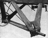
The undercarriage was of plain wooden V-strut configuration with the wheel axle attached to the strut apices by stout rubber cord binding. Early aircraft featured fairly short undercarriage struts, and there was some risk of damaging the big propeller if the tail was raised too high during take-off. Later, as engine power increased sharply and propellers were accordingly enlarged, the undercarriage V-struts were lengthened, and this design came to be adopted in production, no matter what engine was fitted.
The D.H.4's bomb load varied between four 100 or 112 lb bombs and a pair of 230 lb weapons, normally carried on racks under the lower wings but occasionally under the fuselage; there were occasions when eight 65 lb bombs were carried, although these were considered to be a waste of limited resources when they could be carried by corps reconnaissance aircraft. In truth, the D.H.4 was the RFC's first truly effective, purpose-designed bomber and its operations tended to be confined to set-piece raids against targets behind the German lines.
For all the promise shown by the prototype BHP engine, its introduction into production was far from straightforward, and demanded extensive simplification and redesign. Indeed, these changes delayed the first production deliveries for almost a year. However, de Havilland was already aware that Rolls-Royce had successfully bench-run a promising vee-twelve, water-cooled engine as long ago as May 1915, but production examples of this had been earmarked for naval aircraft, not least the Handley Page O/100.
By the end of 1916, when the extent of modifications required by the BHP became known, the production rate of 250hp Rolls-Royce Mk III engines (now named the Eagle III) had reached the stage at which adequate quantities could be allocated to production D.H.4s. An initial order for fifty aircraft was therefore placed with Airco for urgent delivery to the RFC, and the first reached No 55 Squadron at Lilbourne, replacing F.K.8s, in January 1917, and was taken to its base at Fienvillers in France on 6 March. (No 55 Squadron continued to fly D.H.4s until January 1920.)
As further production contracts were raised with Airco, and sub-contracts placed with Westland, F W Berwick and Vulcan, No 55 Squadron remained the only operational RFC D.H.4-equipped unit during 'Bloody April' and in the Battle of Arras. The Squadron's first operational sortie was a bombing attack against Valenciennes railway station by six aircraft on 6 April. Possessing excellent performance and tractable handling qualities the D.H.4, unlike the R.E.8 and F.K.8, was usually able to make good its escape when confronted by enemy fighters, simply by using its superior climb and speed margin; it was, after all, primarily a bomber and was armed with no more than a single forward-firing Vickers gun and a Scarff-mounted Lewis in the rear.
If there was one criticism of the D.H.4, it was that the two cockpits were placed too far apart, the pilot being located well forward so as to possess a good field of view downwards over the lower wing leading edge, and the observer well aft to combine a wide field of view with an effective field of fire if attacked. It was therefore almost impossible for the two crew members to communicate, as the speaking tube between them was of little value in a dogfight.
The heavy losses suffered by so many other RFC squadrons during April 1917 lent further urgency to continue reequipping and, during the following month, Nos 18 and 57 Squadrons received Airco-built D.H.4s, followed by No 25 Squadron in June. By the end of the year six squadrons were fully equipped with the aircraft.
Meanwhile, as development of the Rolls-Royce Eagle was continuing apace, much work was being done to examine alternative powerplants. The BHP eventually appeared in production form and joined the aircraft assembly lines, as did the Factory's 200hp R.A.F.3A - this version serving with No 18 Squadron in France and No 49 at home - and the 200hp Fiat. The last-named engine had been selected for a consignment of D.H.4s intended for supply to Russia in the late summer of 1917, but the Revolution intervened, taking that nation out of the War. As a result the Fiat D.H.4s were diverted to the Western Front. The other engine that came to be fitted in production D.H.4s was the 230hp Siddeley Puma, but none of these alternative engines could match the excellent 375hp Eagle VIII which, by the end of 1917, powered the majority of frontline D.H.4s.
****
From the outset the Admiralty expressed an interest in acquiring D.H.4s, with which to equip RNAS light bomber squadrons in France and elsewhere, and a total of about 90 is thought to have been built to naval requirements by Westland, the majority of them powered by Eagle and BHP engines; about 16 others, with Eagles and R.A.F 3As, were also transferred from War Office production.
The naval D.H.4s differed from the RFC version in being armed with a pair of front Vickers guns, and the observer's gun ring, instead of being recessed into the rear fuselage decking, was raised so as to be level with the top decking profile.
RNAS D.H.4s began equipping No 2 (Naval) Squadron at about the same time as the RFC squadrons began bombing raids in April 1917, and No 5 (Naval) Squadron also re-equipped during the summer of that year. In all, eight operational RNAS squadrons flew D.H.4s, of which four were based in Italy and the Aegean during 1918, their role being to mount long-range bombing attacks over the Balkans.
It may be a matter of interest to note that, although fewer D.H.4s were produced than the much inferior F.K.8 tactical reconnaissance bomber, the D.H. enjoyed far greater operational utilisation, yet actually began to decline in numbers with the RFC from the spring of 1918. This was principally on account of the hopes pinned on the D.H.9, a direct development of, and similar in most respects to the D.H.4.
At the time when an independent bombing force was being assembled, during the winter of 1917-18 when it was designated the 41st Wing of the RFC and commanded by Lt-Col Cyril Louis Norton Newall (later Marshal of the RAF Lord Newall GCB, OM, GCMG, CBE, AM), Maj-Gen Hugh Trenchard scornfully deprecated the use of such aircraft as the F.E.2B and D.H.4 as already being obsolescent. The widespread belief that the D.H.9 would constitute a significant advance over the D.H.4 prompted the War Office prematurely to initiate contracts for the D.H.9 before it became apparent that much work needed to be done before that aircraft was fully ready for service.
Thus it was that by mid-1918 there were still only nine RAF D.H.4 bomber squadrons in France (including four recently transferred from the former RNAS). Eight further squadrons, employed on home defence and training duties, were based in Britain.
Many D.H.4s came to be employed for experimental purposes, including use as test beds for other engines such as the Eagle VI (in A7401), the 300hp Renault 12Fe (in A2148), the R.A.F.4D (A7864), and the 400hp Sunbeam Matabele (A8083); another D.H.4 was flown in 1919 with an experimental Rolls-Royce Type G engine.
And while the War Office (and later the new Air Ministry) decided to replace the D.H.4 with the D.H.9, the United States, having laid plans in May 1917 to adopt the former in large quantities, persisted with this intention, and eventually produced a total of 3,227 aircraft. The original contracts, placed with three large American manufacturers, were ultimately increased to cover no fewer than 9,500 aircraft - even before the American engine, the 400hp Liberty 12, had been built and bench run.
The first flight by a D.H.4 with the Liberty was made on 29 October 1917, yet during the next twelve months 1,885 US-built examples had been shipped to France for use by the American Expeditionary Force. The D.H.4A, as it was designated, became the only British type built in the USA to give operational service during the War. There was to be an ironic twist of fortune when, after the Armistice, the widely criticised D.H.9 gave way to much-improved D.H.9As, many of which were to be fitted with the American Liberty 12 engine!
Type: Single-engine, two-seat, two-bay biplane light bomber.
Manufacturers: The Aircraft Manufacturing Co Ltd, Hendon, London NW9; F W Berwick & Co Ltd, Park Royal, London NW10; Palladium Autocars Ltd, Putney, London SW15; Waring and Gillow Ltd, Hammersmith, London W6; Westland Aircraft Works, Yeovil, Somerset; Vulcan Motor and Engineering Co (1906) Ltd, Crossens, Southport, Lancashire. (Production of D.H.4B undertaken by five manufacturers in America.)
Powerplant: Prototype. One 230hp B.H.P. water-cooled in-line engine driving four-blade propeller. Production aircraft. 230hp B.H.P., 230hp Puma, 250-375hp Rolls-Royce Eagle (various versions), 200hp R.A.F. 3A and 260hp Fiat. Experimental installations included 300hp Renault 12Fe, 400hp Sunbeam Matabele and 353hp Rolls-Royce 'G', American-built version with Liberty 12A engines.
Structure: Wire-braced wooden structure, fabric- and ply-covered; two spruce wing spars; wooden V-strut undercarriage with rubber cord-sprung wheel axle.
Dimensions: Span, 42ft 4 5/8in; length (B.H.P. and Eagle engines), 30ft 8in; height, (Puma) 10ft 1in, (Eagle VIII) 11ft 0in; wing area, 434 sq ft.
Weights: Puma. Tare, 2,230 lb; all-up, 3,344 lb. Eagle VIII. Tare, 2,387 lb; all-up, 3,472 lb.
Performance: Puma. Max speed, 108 mph at sea level, 104 mph at 10,000ft; climb to 10,000ft, 14 min; service ceiling, 17,400ft; endurance, 4 1/2: hr. Eagle VIII. Max speed, 143 mph at sea level, 133 mph at 10,000ft; climb to 10,000ft, 9 min; service ceiling, 22,000ft; endurance, 3 3/4 hr.
Armament: Max bomb load, 460 lb, comprising combinations of 230 lb or 112 lb bombs on external racks. Gun armament comprised one synchronized forward-firing 0.303in Vickers machine gun on nose decking (two guns on some Westland-built aircraft); observer's cockpit fitted with either Scarff ring or pillar mounting(s) for either one or two Lewis machine guns.
Prototype: One, No 3696, first flown by Capt Geoffrey de Havilland at Hendon in August 1916.
Production: A total of 1,449 aircraft built in Britain for the RFC and RNAS: Airco, 960 (A2125-A2174, A7401-A8089, B1482, C4501-C4540, D8351-D8430, D9231-D9280 and F2633-F2732); Berwick, 100 (B2051-B2150); Vulcan, 100 (B5451-B5550); Westland, 167 (B3954-B3970, B9476-B9500, D1751-D1775, N5960-N6009 and N6380-N6429); Palladium, 100 (F5699-F5798); Waring and Gillow, 46 (H5894-H5939). Of the above total production, twelve were delivered into store and eventually reached the civil register, and twelve N-registered Westland-built aircraft were re-numbered in the B3954-B3970 batch. Some aircraft were also rebuilt during repair and rc-allocatcd different numbers.)
Summary of RFC and RNAS Service: D.H.4s served with Nos 18, 25, 27, 49, 55 and 57 Squadrons, RFC and RAF on the Western Front; Nos 30 and 63 Squadrons, RFC and RAF, in Mesopotamia; Nos 223, 224, 226 and 227 Squadrons, RAF in the Aegean; and with the Russian contingent at Archangel. D.H.4s served with Nos 5, 6 and 11 Squadrons, RNAS (later Nos 205, 206 and 211 Squadrons, RAF) on the Western Front; Nos 2, 5 and 17 Squadrons, RNAS (later Nos 202, 205 and 217 Squadrons, RAF) on Coastal Patrol, based in Britain; and at RNAS Stations, Great Yarmouth, Port Victoria and Redcar (becoming Nos 212 and 273 Squadrons, RAF). D.H.4s also served on Nos 31 and 51 Training Squadrons, RFC, Air Observers' Schools, the Reconnaissance School at Farnborough and various armament schools.
Показать полностью
P.Lewis British Bomber since 1914 (Putnam)
Another two-seat bomber making its debut in 1916, but one which was destined to make its mark among the most successful and significant British aircraft of the 1914-18 War was Geoffrey de Havilland’s outstanding D.H.4, to the design of which A. E. Hagg made a considerable contribution.
By this period the basic requirements of performance had brought a fairly definite degree of rationalization and standardization in bomber layout, and the new Airco product followed without deviation the two-seat tractor biplane formula in meeting the requirement for a new advanced day bomber. The disappointment felt at the lack of progress made towards acceptance of the D.H.3 was quickly forgotten in the certain knowledge that in the D.H.4 the team at Hendon were evolving a winner. An excellent appearance characterized the well-proportioned machine which made its initial flight piloted by Geoffrey de Havilland, accompanied by Maj. G. P. Bulman, in the middle of August, 1916.
The 160 h.p. Beardmore was scheduled in the first instance as the D.H.4’s engine, but advantage was taken of the new unit being developed simultaneously by F. B. Halford and which emerged as the 230 h.p. Beardmore-Halford-Pullinger. The new B.H.P. was installed in the prototype D.H.4, but delays in production of the six-cylinder inline B.H.P. led to the more powerful and first-class twelve-cylinder vee 250 h.p. Rolls-Royce Eagle being used for the early production D.H.4s.
The basic design earned high praise in its official trials, those of the prototype being conducted from 21st September, 1916, until 12th October, 1916, by the Central Flying School’s Testing Flight. In every way, the D.H.4 justified the high hopes of its creators and was taken to France on 6th March, 1917, for its first active service with No. 55 Squadron, R.F.C. No time was lost in developing the basic design through minor airframe modifications and in fitting engines of progressively higher power. Eventually, with the 375 h.p. Eagle VIII, the D.H.4’s top speed reached 133-5 m.p.h. at 10,000 ft., and an absolute ceiling of 23,000 ft. was achieved. Apart from its virtues in allied roles, the D.H.4 was unrivalled as a day bomber in its time and played a great part in taking the war to the enemy. Armament generally comprised a pilot’s Constantinesco-synchronized .303 Vickers mounted to port on the decking and a .303 Lewis on a Scarff No. 2 ring for the observer. The basic offensive load, in racks beneath the lower wings, consisted of two 230 lb. or four 112 lb. bombs or their equivalent. Very successful use of the D.H.4 was made also by R.N.A.S. squadrons.
Показать полностью
J.Bruce British Aeroplanes 1914-1918 (Putnam)
de Havilland 4
IN the D.H.4, Captain de Havilland produced one of the truly great aeroplanes of its day, one which had no peer among aircraft of its class in any of the combatant air forces, Allied or enemy. It was designed in response to an official request for an aeroplane to be used for day-bombing duties, and was the first British aircraft to be specifically designed for that purpose.
The power unit originally specified for the D.H.4 was the 160 h.p. Beardmore. That engine had been developed from the 120 h.p. Beardmore by F. B. Halford, and it was thanks to his skill that the 33 1/3 per cent increase in output was achieved. By the time when the D.H.4 design was being prepared, Halford had secured the cooperation of Sir William Beardmore and T. C. Pullinger in the design and manufacture of a new engine, the 230 h.p. B.H.P., or Beardmore-Halford-Pullinger.
The B.H.P. was similar to the Beardmore, for it was an upright six-cylinder in-line engine. It had, however, cylinders of cast aluminium monobloc construction with steel liners. In the adoption of this form of construction Halford had been inspired by the Hispano-Suiza engine, an example of which he had seen in France in 1915.
The first B.H.P. engine was running in June, 1916, and gave good results. After successfully completing its bench tests, it was installed in the prototype D.H.4 instead of the specified 160 h.p. Beardmore. It was a taller engine than the Beardmore, a fact which doubtless accounted for the “step” in the top line of the engine cowling of the aeroplane. With the B.H.P. engine the D.H.4 appeared at Hendon in August, 1916. Difficulties were encountered in the quantity production of this engine, however; in fact, the first production B.H.P.s did not appear until the middle of 1917.
Fortunately, an excellent alternative power unit was available: it was the 250 h.p. Rolls-Royce liquid-cooled vee-twelve engine which came to be known as the Eagle. This engine had originally been made for installation in seaplanes, but development and production had proceeded steadily from the time of the first bench test in May, 1915. The production Rolls-Royce engines had been coming off the lines since October, 1915, and by the end of 1916 sufficient quantities were available to enable the first production D.H.4s to be fitted with this type of engine.
Tests of the D.H.4 with both the B.H.P. and Rolls-Royce engines were highly successful, and the happy union with the latter motor enabled sufficient machines to be produced to equip No. 55 Squadron, R.F.C., before it went to France on March 6th, 1917. Later marks of the superb Eagle engine were fitted to the D.H.4 as development of the motor progressed; and with the Eagle VIII, which delivered 375 h.p., the aircraft had a better performance than most contemporary fighters.
The basic structural design of the D.H.4 was typical of its period. It was almost entirely made of wood, with wire cross-bracing and fabric covering. The fuselage was a conventional box-girder, but was made in two portions which were connected by fishplates immediately behind the observer’s cockpit; the forward portion was covered with plywood, which increased its strength considerably. The wings had two spruce spars, spindled out between the compression ribs, and the balance cables which interconnected the upper ailerons ran externally above the upper wing. The tailplane was also a wooden structure, and its incidence could be adjusted in flight by the pilot. The undercarriage was simple and strong: it consisted of two substantial wooden vees, to the apices of which the axle was bound by rubber cord.
As the power of the engine was successively increased, larger airscrews were fitted, and it was found that the original undercarriage did not give sufficient ground clearance. A taller undercarriage was therefore fitted and became standard on all later production D.H.4s, regardless of the type of engine installed in the machine.
The B.H.P.-powered prototype had its rear centre-section struts inclined forwards in side elevation; this arrangement did not appear in any production D.H.4s. There was a rather unsightly step-down in the top line of the engine cowling; the exhaust manifold terminated in a vertical stack which led the exhaust gases above the upper wing; and the engine drove a four-bladed airscrew.
The B.H.P. engine had to be modified in several ways to make it suitable for large-scale production. An unfortunate result of these modifications was that when the first batch of engines was delivered to the Aircraft Manufacturing Co. in July, 1917, it was found that they would not fit the D.H.4s: the engine mountings in the aircraft had been designed from early drawings of the B.H.P. engine. The airframes had to be returned to the shops for modification, and production was delayed. The machines which emerged had a much neater engine installation than the B.H.P.-powered prototype; some had stack exhausts, but quite a number had a simple horizontal manifold.
The various marks of Rolls-Royce Eagle had an exhaust manifold on each side of the engine: in many cases these manifolds were led up into twin stacks in front of the leading edge of the upper wing, but the stack extensions were not fitted to late production D.H.4s.
Other alternative power units which were fitted to production D.H.4s were the 200 h.p. R.A.F. 3a vee-twelve, the 260 h.p. Fiat, and, as a natural alternative to the B.H.P. engine, the 230 h.p. Siddeley Puma. The R.A.F. 3a installation was characterised by a single central exhaust stack, a radiator which tapered slightly from top to bottom, and a four-bladed left-hand airscrew. This version of the D.H.4 was used by Squadrons Nos. 18 and 49.
The installation of the Fiat engine made the nose of the D.H.4 resemble that of the later D.H.9; and this was the only production version of the machine which did not have a flat frontal radiator immediately behind the airscrew. The first installation was made in A.7532.� The history of the Fiat-powered D.H.4s is of unusual interest. At the beginning of September, 1917, a hundred Russian pilots were receiving flying training in England, and fifty D.H.4s were under construction for the Russian Government. For these machines Russia had bought Fiat engines in Italy. At this time, however, the British War Cabinet decided to initiate a campaign of bombing raids on German towns in retaliation for the Gotha raids on London which had begun in September. In consequence of this decision it became imperative to augment the British bomber forces in France, and Russia was asked to forgo delivery of her fifty D.H.4s on the understanding that she would receive seventy-five in their place in the spring of 1918. Winter was approaching and operations on the Russian Front would be brought to a standstill by the weather, so the Russian Government agreed to the British request. On October 2nd, 1917, twenty of these D.H.4S were completed and crated for despatch to Russia, but as a result of the bargain they were diverted to the Western Front.
No Fiat-powered D.H.4s were used operationally by the 41st Wing (the forerunner of the Independent Force), but the diversion of the Russian D.H.4s to other duties on the Western Front released Rolls-Royce D.H.4s for the independent bombing operations.
A purely experimental engine installation in an early D.H.4 was that of a 300 h.p. Renault: this was probably made in France.
Early production D.H.4s had the observer’s Scarff ring-mounting immediately on top of the upper longerons and below the level of the fuselage top-decking. With the gun-ring at this level, the decking interfered with the free movement of the gun and was rather low for comfort. In later D.H.4s the gun-ring was raised to the level of the top of the decking, thereby increasing the effectiveness of the observer’s weapon. The decking aft of the rear cockpit was flat-topped in these later machines.
The early Westland-built D.H.4s supplied to the R.N.A.S. differed slightly from the standard machine. The Rolls-Royce Eagle was fitted, usually without radiator shutters, and in some machines the rocker-heads were cowled over. Twin Vickers guns were provided for the pilot in place of the customary single gun, and the observer’s gun-ring was built up to the top of the fuselage decking; the decking retained its rounded form right down to the tail, however. The weight of the additional Vickers gun and interrupter gear, and the drag of the externally mounted gun reduced the performance somewhat.
In the air, the D.H.4 handled well for a two-seater, and the Central Flying School reported on it in the following glowing terms:
“Stability. - Lateral very good; longitudinal very good; directional very good. Control. - Stick. Dual for elevator and rudder. Machine is exceptionally comfortable to fly and very easy to land. Exceptionally light on controls. Tail-adjusting gear enables pilot to fly or glide at any desired speed without effort.”
That report related to the prototype, but the D.H.4 retained its good handling characteristics throughout its development. A later report on the version with the Eagle VIII engine notes that the machine tended to be tail-heavy at full speed and nose-heavy with engine off, but that the manoeuvrability remained very good.
In performance the D.H.4 surpassed all contemporary aeroplanes in its class, and bettered most of the fighting scouts then in service. Its high ceiling particularly commended it to the bomber pilots of its day, and this desirable combination of speed, climb and tractability would at first glance seem to make the D.H.4 well-nigh invincible. More than once its speed and ceiling enabled it to escape from enemy fighters, but if it were intercepted and forced to fight it sometimes proved to be a comparatively easy victim. This vulnerability was attributed to the considerable distance which separated the pilot and observer.
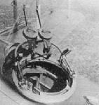
The cockpits were arranged to give the pilot a good forward and downward view for bombing, and the observer a good field of fire for his Lewis gun. Thus the pilot’s cockpit was situated immediately under the centre-section, and the observer was several feet further aft; the main fuel tanks occupied the intervening space. This arrangement succeeded in its original object, but the distance between the cockpits prevented that close and immediate cooperation between pilot and observer which was so essential in combat. The speaking-tube which connected the cockpits was of little practical use, and the fighting efficiency of the aeroplane suffered considerably from the separation of its crew. The observer had full dual control, with duplicated altimeter and air-speed indicator; his control column was detachable.
No. 55 Squadron, R.F.C., took the first D.H.4s to France on March 6th, 1917, and from that day until the Armistice twenty months later the machine served with the R.F.C., R.N.A.S. and R.A.F. as a day-bomber, fighter-reconnaissance, photographic, anti-Zeppelin and anti-submarine aeroplane. No. 55 Squadron arrived in time to take part in the Battle of Arras, and made their first operational sortie on April 6th, 1917, when six D.H.4s attacked Valenciennes railway station. Valenciennes was attacked several times by the squadron, and on May 3rd the D.H.4s bombed the railway junctions at Busigny and Brebieres. Machines of this unit also carried out long-range photographic reconnaissances: these missions were flown by single D.H.4S at heights between 16,000 and 21,000 feet.
No. 57 Squadron began to re-equip with D.H.4s in May, 1917, and was able to participate in the Battle of Ypres in company with No. 55 Squadron. In June, 1917, No. 18 Squadron was re-equipped with D.H.4s; No. 25 followed suit in July; No. 49 Squadron arrived in France on November 12th equipped with the type; and in the same month No. 27 Squadron began to replace their Martinsyde Elephants with D.H.4s. The four last-named squadrons were in action during the Battle of Cambrai, and in the period preceding the great German offensive of March, 1918, the D.H.4s of Nos. 25 and 49 Squadrons were employed on photographic reconnaissance.
During the offensive itself, the D.H.4s of No. 5 (Naval) Squadron joined the day-bomber force, and all units were actively employed against the advancing enemy forces. Until March 25th, four days after the beginning of the enemy offensive, the D.H.4s had bombed from heights of 14,000 to 16,000 feet, and the effect of their bombs had been more moral than destructive. This height was adhered to because of an order issued in August, 1917, when D.H.4s were scarce, which stated that the type was not to be used below 15,000 feet. By March 25th, 1918, the situation had become so critical that Major-General J. M. Salmond had ordered the squadrons of the 9th Wing to make low-flying attacks; all risks were to be taken. This order concerned Squadrons Nos. 25 and 27, and on the following day No. 5 (Naval) Squadron was placed under similar orders. Despite unfavourable weather, these units carried out their orders to the letter, and played a leading part in harassing enemy troops. Low-flying attacks were also made by Nos. 18 and 49 Squadrons, but by March 31st the D.H.4s were able to resume bombing from more comfortable altitudes.
When the German forces were beaten back throughout the summer and autumn of 1918, the D.H.4s again gave of their best. They acquitted themselves with more distinction than the D.H.9s, which were then coming into service and were replacing the D.H.4 in several squadrons. No. 205 Squadron, R.A.F. (as No. 5 Naval had become on April 1st, 1918), distinguished itself in repeated attacks on strategic bridges, and during four days in August, 1918, the D.H.4s of this unit flew for 324 hours 13 minutes and dropped a total of 16 tons of bombs.
At the beginning of October, 1917, No. 55 Squadron had been withdrawn from the British front, and became one of the three units composing the 41st Wing: the two others were No. too (F.E.2b) Squadron and No. 16 (Naval) Squadron, which had Handley Page O/100s. These squadrons formed the nucleus of what was successively named the VIII Brigade and, on June 6th, 1918, the Independent Force, R.A.F. From their base at Ochey they carried out the first organised programme of strategic bombing.
On October 17 th, 1917, eight of the D.H.4s of No. 55 Squadron made their first raid after joining the 41st Wing. The objective was Saarbrucken, which was revisited many times by No. 55 in the course of the ninety-four further sorties made by the squadron before the Armistice. Other towns in which the D.H.4s made the lot of the munition workers an unhappy one were Mannheim, Metz-Sablon, Kaiserslautern, and Frankfurt. Raids on Frankfurt, Duren and Darmstadt extended the D.H.4s to the limit of their maximum endurance of five and a half hours, and there was no safety margin for combat. In Cologne, a minor panic followed an attack by six D.H.4s on May 18th, 1918, for the town had been attacked only twice before. That was not the only occasion on which No. 55 Squadron bombed Cologne, however.
These operations cost No. 55 Squadron sixty-nine D.H.4s. Eighteen were missing and fifty-one wrecked.
The R.N.A.S. began to receive D.H.4s in the spring of 1917, and the first overseas unit to receive the type was No. 2 (Naval) Squadron at St Pol, followed by No. 5 (Naval): the latter unit had completely replaced its Sopwith 1 1/2-Strutters by the middle of August, 1917. In addition to day-bombing attacks, these R.N.A.S. D.H.4s did much useful coastal patrol work. The D.H.4s of No. 202 Squadron spent weeks in taking photographs of the whole area and defence system around Zeebrugge before the naval attack of April 22nd/23rd, 1918.
For anti-submarine patrol, No. 17 (Naval) Squadron was formed with D.H.4s on January 13th, 1918; and 1918 saw the former Naval fighting squadrons Nos. 6 and 11 revived and initially equipped with D.H.4s. The submarine U.B.12 was sunk on August 12th, 1918, by four D.H.4s of No. 217 (formerly No. 17 Naval) Squadron. Captain K. G. Boyd scored direct hits with his two 230-lb bombs.
R.N.A.S. units in England received D.H.4s for anti-Zeppelin patrols. Great Yarmouth air station received its first D.H.4 in August, 1917, and welcomed it as an overdue replacement for the B.E.2c’s which had been the unit’s best night-flying aeroplane up to that time. On August 26th two D.H.4s of unusual interest arrived at Great Yarmouth. These were special long-range machines, powered by the R.A.F. 3a engine and fitted with tanks which would give them an endurance of about fourteen hours.
The long-range D.H.4s had been specially modified to make a photographic reconnaissance of the Kiel Canal. The take-off was to have been made from Bacton, whence the machines were to fly across the North Sea, take their photographs, and land at Dunkerque. These D.H.4s were specially camouflaged with matt dope of fawn and blue. They were flown to Bacton on August 9th, 1917, but a few days later the Admiralty decided not to proceed with the plan, and the D.H.4s were sent to Great Yarmouth for anti-Zeppelin duties.
On September 5th, 1917, one of the Great Yarmouth D.H.4s collaborated with the Curtiss H.12 flying-boat No. 8666 in attacking the Zeppelin L.44. The airship escaped, but the D.H.4 developed engine trouble and had to ditch. The port engine of the flying-boat was not running well, but Flight-Lieutenant R. Leckie went down at once and rescued Flight-Lieutenant A. H. H. Gilligan and Lieutenant G. S. Trewin from the wreckage of their D.H.4. This early attempt at air-sea rescue nearly ended in disaster, for the flying-boat was unable to take off again. Leckie taxied towards England until his fuel ran out, and the six men were not picked up until September 7th when they were sighted by H.M.S. Halcyon.
These R.N.A.S. D.H.4s had no flotation gear of any kind, but experiments with the Grain Flotation Gear were carried out at the Marine Experimental Aircraft Depot, Isle of Grain. D.H.4s with Siddeley Puma and R.A.F.3a engines were used; one of the Puma-Fours was tested with flotation gear in January, 1918. Tests were also carried out with D.H.4s which had a biplane hydrovane mounted ahead of the undercarriage: the wheels were jettisoned by means of compressed air before alighting. Inflatable canvas bags were attached to the lower longerons and small stabilising floats were fitted under the lower wingtips.
A twin-float version of the D.H.4 existed, and may have been an attempt to provide a patrol seaplane with a worthwhile performance. The D.H.4 seaplane had a Rolls-Royce Eagle engine, and its floats resembled those of the Wight seaplanes; there was no tail float.
A D.H.4 from Great Yarmouth shot down the Zeppelin L.70 on August 5th, 1918. On board the airship was Fregattenkapitan Peter Strasser, the Commander-in-Chief of the Imperial German Naval Airship Service, and his death was a severe blow to the enemy. The D.H.4, A.8032, was flown by Major Egbert Cadbury, and his gunner was Captain Robert Leckie, D.S.O., D.S.C. Cadbury attacked the airship from ahead and slightly to port at a height of 16,400 feet about forty miles north-east of Yarmouth. Leckie’s Lewis gun was loaded with Z.P.T. ammunition which instantly set fire to the Zeppelin, and Cadbury later estimated that the whole ship was consumed by the flames in about three-quarters of a minute. Cadbury then turned on the L.65, which was accompanying the L.70, but Leckie’s gun jammed and the airship escaped.
At the time, it could not be known that the night of the L.yo’s end marked the last of the Zeppelin raids on the United Kingdom, and work continued on various means of overcoming the Zeppelin menace. It was thought that the Coventry Ordnance Works 1 1/2-pounder quick-firing gun would be an effective weapon for anti-airship work, and two D.H.4s were specially modified to carry a gun of this type: one of these machines was A.2168. In these D.H.4s the gun was fixed to point upwards at an acute angle; the breech was close to the floor of the rear cockpit, and the muzzle protruded through the upper centresection, which had to be covered with sheet metal to withstand the blast. The gun was aimed in a fashion similar to that adopted on Home Defence Bristol Fighters. The pilot had a sight mounted parallel to the C.O.W. gun, and this he aligned with the target by careful use of the. elevators, whereupon he gave the gunner the signal to fire.
The airframes of the D.H.4s had to be extensively strengthened to withstand the recoil of the gun; consequently they were overloaded and rather unpleasant to fly. An added discomfort for the pilot was the firing of the gun immediately behind his head.
By the time the C.O.W.-gun D.H.4s were ready, Zeppelin raids on the United Kingdom had ceased. A night test over the enemy lines was ordered, but the Armistice was signed a few days after the machines arrived in France, and they saw no operational service.
The D.H.4 was used in experiments with the provision of parachutes for aircrew. A Puma-powered D.H.4 was tested with two Guardian Angel parachutes in November, 1918.
Further experimental engine installations were tested in 1918. One was the 400 h.p. Sunbeam Matabele, which was flown in the D.H.4 numbered A.8083. The engine was a vee-twelve with cylinders of the same bore and stroke as those of the Sunbeam Saracen, an earlier six-cylinder in-line engine.
Of much greater significance was the installation in a D.H.4 of the experimental Ricardo-Halford Inverted Supercharger engine. F. B. Halford first met H. R. (later Sir Harry) Ricardo early in 1916, and soon became his enthusiastic disciple and collaborator. Ricardo did a prodigious amount of inspired work in the design of aircraft engines and the development of their fuels, but his pioneering efforts have received comparatively little recognition.
In 1918 Ricardo and Halford, working independently of the Royal Aircraft Factory’s experiments with supercharged engines, collaborated in the design of the Ricardo Supercharger, one of the first engines to be designed from the start as a supercharged power unit. When it was completed, the engine was unusually tall, and it would have been difficult to devise an installation which did not block the pilot’s view. Halford conceived the idea of inverting the engine, and did much of the design work connected with the necessary modifications. The Ricardo-Halford Inverted Supercharger was installed in a D.H.4 and was successfully flown at Farnborough.
The first D.H.4s to reach Mesopotamia were two which were allotted to No. 30 Squadron. Neither survived for long: one received a direct hit by an anti-aircraft shell and blew up in the air on January 21 st, 1918, and the second caught fire at 1,000 feet during a raid on Kifri on the night of January 25th/26th. The latter machine landed in time to enable its crew to escape.
Later, a few D.H.4s were on the strength of “A” Flight of No. 72 Squadron, which had arrived at Basra on March 2nd.
The R.N.A.S. units on the Aegean Islands of Imbros, Lemnos, Mitylene and Thasos used D.H.4s. The unit known as “C” Squadron moved to a new aerodrome at Gliki, on Imbros, in October, 1917; and during the following month the two D.H.4s which had been sent to reinforce the squadron began a series of attacks on the main Sofia-Constantinople railway.
On January 20th, 1918, the D.H.4s of the R.N.A.S. began a sustained attack on the German cruiser Goeben when she had run aground in the Narrows after coming out of the Dardanelles. The attacks continued by day and night until January 24th, but no hits were scored, and the Goeben returned to Constantinople on the 27th. A watch was kept on her as she lay at her moorings in Stenia Bay by D.H.4s specially fitted with long-range tanks to ensure an endurance of seven hours.
One of the D.H.4s from Mudros went to the aerodrome at Amberkoj on September 24th, 1918, to assist No. 17 Squadron in its attacks on the retreating Bulgars.
The Italian-based D.H.4s of the 66th and 67th Wings made several attacks on the enemy submarine bases at Cattaro and Durazzo. Attacks on Cattaro entailed a flight of 400 miles over the sea.
Among the machines which went to northern Russia with the R.A.F. contingent in May, 1918, were eight D.H.4s with R.A.F. 3a engines: these operated with a special force which was sent to Archangel. Later in the campaign some Fiat-powered D.H.4s joined the R.A.F. contingent. After the Armistice was signed, the R.A.F. remained on active service in Russia, and another unit was set up at Baku in January, 1919, to support British naval forces in the Caspian Sea. The equipment of this unit included D.H.4s which carried out bombing raids on Astrakhan and other ports until October, 1919, when the R.A.F. unit was recalled. At least one D.H.4 was used by the Red aviation service after it had been captured intact.
Of all the British aeroplanes which were selected for production in America, only the D.H.4 was produced in substantial numbers. It was the only American-built British type to see operational service in France.
Even before the Liberty engine was designed, the original procurement programme of 7,375 aeroplanes presented to the Secretaries of the War and Navy Departments on May 25th, 1917, included 1,700 D.H.4s. The fact that the D.H.4 was obviously capable of using the American-designed Liberty 12 engine made it highly desirable in American eyes.
The first D.H.4 to be flown in America was a British-built machine which had been delivered, without engine, to Dayton, Ohio, on August 15th, 1917. Ten days later the first Liberty 12 successfully completed a fifty-hour bench run, and was rated at 314 h.p. By October, 1917, the power output had been raised to 395 h.p., and on the 29th of that month the engine was flown in the D.H.4 for tbe first time.
Contracts for the production of the D.H.4 were placed with the Dayton-Wright, Fisher Body and Standard concerns, from whom a total of 9,500 machines were ordered; and by the time of the Armistice these manufacturers had produced a total of 3,227 Liberty-powered D.H.4s. The first production aircraft were delivered by Dayton-Wright in February, 1918. Before the end of the war, 1,885 American-built D.H.4s were despatched to France for the use of the American Expeditionary Force, and the type was used operationally by twelve squadrons. The first American-built D.H.4 joined the A.E.F. on May 11 th, 1918.
Development proceeded in America, and in July, 1918, the Engineering Division of the Bureau of Aircraft Production installed a revised fuel system in a D.H.4, which was thereupon re-designated D.H.4A (but should not be confused with the British post-war commercial D.H.4A). The second modification of the D.H.4, made in October, 1918, by the Engineering Division, was the D.H.4B. This was the D.H.4A with the positions of the pilot and fuel tanks interchanged.
American production ceased with the Armistice, when seven contracts for a total of 7,502 D.H.4s were cancelled; but during the period 1919-23 many hundreds of D.H.4s were converted to D.H.4Bs: 1,538 were modified by ten different contractors from February, 1919, onwards, and many others were similarly converted by air depots. The type survived for many years in America, and scores of variants of the basic design appeared over the years. In 1923-24, some 285 D.H.4s and D.H.4Bs were given steel tube fuselages by the Atlantic and Boeing concerns: these machines were re-designated D.H.4M, D.H.4M-1 and D.H.4M-2. Numbers of surplus D.H.4s were taken over by the Post Office Department in 1919, and were modified to carry air-mail: in this capacity the type served until 1927. This version of the D.H.4 was not particularly pleasant to fly and was not popular with its pilots. The first twelve machines converted by the L.W.F. Engineering Co. were fitted with a rain-proof compartment for 500 lb of mails in what was originally the front cockpit. The machine was flown from the rear seat, and a steel tube undercarriage was fitted.
At home, the post-war use of the D.H.4 was almost wholly commercial in character, beginning with its use by the R.A.F. Communications Wing during the 1919 Peace Conference, when a London-to-Paris service was operated. In that year a cabin version, designated D.H.4A, appeared: there was accommodation for two passengers. Another post-war version was the drastically modified D.H.4R racer with clipped lower wings and a 450 h.p. Napier Lion engine. The D.H.4R won the 1919 Aerial Derby, and was capable of 150 m.p.h.
In July, 1919, a D.H.4 was used to test an experimental Rolls-Royce engine known as the Experimental G. This power unit gave 353 h.p. at 1,800 r.p.m.
After the end of the war, D.H.4s were sold to Greece and Spain, and individual machines went as far afield as Japan, New Guinea and Australia. In Canada, the type was used as a forestry patrol aircraft for several years.
SPECIFICATION
Manufacturers: The Aircraft Manufacturing Co., Ltd., Hendon, London, N.W.
Other Contractors: F. W. Berwick & Co., Ltd., Park Royal, London, N.W.10. Westland Aircraft Works, Yeovil, Somerset. Vulcan Motor and Engineering Co. (1906), Ltd., Crossens, Southport.
American Contractors: The Dayton-Wright Airplane Co., Dayton, Ohio; The Fisher Body Corporation; Standard Aircraft Corporation, Elizabeth, New Jersey.�
For conversions to D.H.4B: The Aeromarine Plane and Motor Co., Keyport, New Jersey; Gallaudet Aircraft Corporation, East Greenwich, Connecticut; The L.W.F. Engineering Co., College Point, New York; Thomas-Morse Aircraft Corporation, Ithaca, New York.
Power: 230 h.p. P.H.P. (both Galloway and Siddeley-made); 230 h.p. Siddeley Puma; 250 h.p. Rolls-Royce Mk. Ill (Eagle III); 275 h.p. Rolls-Royce Mk. II (322 h.p. Eagle VI); 275 h.p. Rolls-Royce Mk. Ill (325 h.p. Eagle VII); 375 h.p. Rolls-Royce Eagle VIII; 353 h.p. Rolls-Royce Experimental G engine; 200 h.p. R.A.F. 3a; 400 h.p. Sunbeam Matabele; 260 h.p. Fiat; 300 h.p. Renault; 400 h.p. Liberty 12; Ricardo-Halford Inverted Supercharger.
Dimensions: Span: 42 ft 4 5/8 in. (American-built D.H.4: 42 ft 5 3/4 in.). Length: 29 ft 8 in. with R.A.F. 3a and Fiat engines, 30 ft 8 in. with Rolls-Royce and Puma engines, 30 ft 5 61/64 in. with Liberty. Height: 10 ft 1 in. with B.H.P., Puma and Rolls-Royce G engines; 10 ft 3 20/32 in. with Liberty; 10 ft 5 in. with R.A.F. 3a, Eagle III and Fiat engines; 11 ft with Eagle VIII engine. Chord: 5 ft 6 in. Gap: 5 ft 6 in. Stagger: 12 in. Dihedral: 30. Incidence: 30. Span of tail: 14 ft (American-built D.H.4: 13 ft 7 in.). Wheel track: 6 ft. Airscrew diameter: B.H.P. and Eagle III, 8 ft 9 in.; Fiat, 8 ft 11 in.; R.A.F. 3a, 10 ft; Eagle VIII, 10 ft 2 in.
Areas: Wings: upper 223 sq ft, lower 211 sq ft, total 434 sq ft. Ailerons: each 20-5 sq ft, total 82 sq ft. Tailplane: 38 sq ft. Elevators: 24 sq ft. Fin: 5-4 sq ft. Rudder: 13-7 sq ft.
Tankage (in gallons):
Petrol Oil Water
230 h.p. B.H.P. 62 1/2 5 1/2 6
250 h.p. Rolls-Royce 65 4 1/2 -
Rolls-Royce Eagle VIII 65 3/4 5 1/2 9
R.A.F. 3a 65 1/2 4 1/2 -
Fiat 65 5 8
Liberty 88 - -
Armament: Standard armament consisted of one fixed forward-firing Vickers machine-gun mounted on top of the fuselage to port of centre and synchronised by Constantinesco gear; the observer had either a single Lewis gun or a double-yoked pair on the Scarff ring-mounting on the rear cockpit. The Westland-built D.H.4s for the R.N.A.S., some of which were diverted to the R.F.C., had twin Vickers guns for the pilot, and some R.N.A.S. machines had Lewis guns on separate pillar-type mountings in the rear cockpit instead of the Scarff mounting. American-built D.H.4s had two fixed Marlin machine-guns and twin Lewis guns for the observer. Bomb racks were fitted under the fuselage and each lower wing: the bomb load consisted of two 230-lb, four 112-lb bombs, or their equivalent. Depth charges could be carried instead of bombs.
British Production and Allocation: Production of D.H.4s totalled 1,449. Of these, 1,170 were delivered to the R.F.C. and R.A.F.; presumably the remainder went to the R.N.A.S. and into store. 664 went to the Expeditionary Force in France; ninety-one to the Independent Force; eighteen to the Middle East Brigade; one to the Mediterranean in 1918; sixty-seven to the 5th Group in 1918 for anti-submarine patrol (Squadrons Nos. 202 and 217); one to a Home Defence unit in 1917; and 328 to training units.
On October 31st, 1918, the R.A.F. had on charge 548 D.H.4s; 373 with Rolls-Royce engines, seventy-two with R.A.F. 3a, ninety-eight with B.H.P., and five with Fiat. These were distributed as follows:
Rolls-Royce R.A.F. 3a B.H.P. Fiat
With E.F. in France 120 25 12 1
Independent Force 70 - - 2
5th Group 37 - - -
In transit to Middle East - 4 - -
Mesopotamia - 9 - -
Mediterranean 2 4 20 -
Attached to Grand Fleet 4 - - -
11th (Irish) Group - 3 3 -
Training units - - 17 -
Sundry home units 27 17 44 2
Aeroplane Repair Depots 75 6 1 -
With contractors 15 4 1 -
In store 23 - - -
Totals 373 72 98 5
Service Use: Western Front: R.F.C. Squadrons Nos. 18, 25, 27, 49, 55 and 57; R.N.A.S. Squadrons Nos. 5, 6 and 11 (later Nos. 205, 206 and 211, R.A.F.); American units, 8th, nth, 20th, 50th, 85th, 100th, 135th, 155th, 166th, 168th, 278th and 354th Aero Squadrons. The 96th Aero Squadron had a few D.H.4S. Some were used by the U.S. Naval Northern Bombing Group. Coastal Patrol: R.N.A.S. Squadrons Nos. 2, 5 and 17 (later Nos. 202, 205 and 217, R.A.F.), No. 212 (part only), No. 273 (part only), R.N.A.S. Stations Port Victoria and Redcar. Home Defence: R.N.A.S. Great Yarmouth (later No. 212 Squadron, R.A.F.). Mesopotamia: No. 30 Squadron had two D.H.4s; No. 72 Squadron, “A” Flight. Macedonia: one D.H.4 from Mudros (probably No. 223 Squadron) attached to No. 17 Squadron. Aegean: “C” Squadron, Imbros. “D” Squadron, Stavros. R.N.A.S. Station, Mudros. 62nd and 63rd Wings (Squadrons Nos. 220, 221, 222 and 223). Adriatic: 66th and 67th Wings (Squadrons Nos. 224, 225, 226 and 227). Russia: R.A.F. contingent at Archangel (May, 1918) had eight D.H.4s with R.A.F. 3a engines. Fiat-powered D.H.4s were later used in northern Russia. Training: No. 51 Squadron. Air Observers’ Schools at Mansion, New Romney and Eastchurch. School of Photography, Maps and Reconnaissance, Farnborough. Schools of Navigation and Bomb-dropping, Andover, Stonehenge and Thetford. Aerial Fighting Schools at Turnberry, Marske and Sedgeford. No. 10 Training Depot Squadron, Harling Road. No. 31 Training Squadron, Wyton. American version used at Ford junction, Sussex.
Serial Numbers:
Serial No. Contractor Contract No.
3696 Aircraft Manufacturing Co.
A.2125-A.2174
A.7401-A.8089 Aircraft Manufacturing Co. 87/A/496
B.1482
B.2051-B.2150 F. W. Berwick & Co., Ltd.
B.3957-B.3960 Westland-built R.N.A.S.-type D.H.4s, probably renumbered from N series
B.5451-B.5550 Vulcan Motor Co.
B.9476-B.9500 Westland Aircraft A.S.29679
C.4501-C.4540 Aircraft Manufacturing Co. A.S.24960
D.1751-D.1775 Westland Aircraft A.S.29679
D.8351-D.8430 Aircraft Manufacturing Co. A.S.37726
D.923I-D.9280 Aircraft Manufacturing Co.
Between, and about
F.2635-F.2704 -
Between and about
F.5715-F.5828 -
About F.7597 -
N.5960-N.6009 Allotted for D.H.4s to be built by Westland Aircraft, but only the following were delivered: N.5960-N.5990, N.5992, N.5996, N.5997, N.6000, N.6001, N.6004, N.6005, N.6007, N.6009.*
N.6380-N.6399 Allotted for D.H.4s, but N.6393 and N.6397 were not delivered with N. serials.*
N.6400-N.6429 Westland Aircraft
* The missing D.H.4s in these batches may have been delivered to the R.F.C. and renumbered; e.g. B.3957.
Notes on Individual Machines: Used by No. 5 (Naval) Squadron, later No. 205 Squadron, R.A.F.: A.7518, A.7573, A.7620, A.7644, A.7664, A.7739, A.7742, A.7811, A.7908, A.7939, A.7964, A.8071, A.8084, D.9232, D.9238, D.9241, D.9243, N.5962, N.5967, N.5968, N.5971, N.5974, N.5977, N.5978, N.5982, N.5996, N.6000, N.6001, N.6004, N.6005, N.6008, N.6009. Used by No. 17 (Naval) Squadron, later No. 217 Squadron, R.A.F.: A.7772, A.7773, A.7846, A.7863, A.7867, A.7870, A.7875, A.7925, A.7935, A.7964, A.8013, A.8022, A.8050, A.8056, A.8059, A.8067, A.8072, D.8353, D.8366, D.8370, D.8393. Used at R.N.A.S. Station, Mudros: N.6410, N.6411, N.6420. Used by “C” Squadron, R.N.A.S., Gliki, Imbros: N.5975, N.5976. Used by No. 18 Squadron, R.F.C.: A.7550 (R.A.F. 3a engine), A.7594, A.7614, A.7653, A.7815, A.7907, A.8000, A.8041. Used by No. 25 Squadron: A.7442 (“B”), A.7477, A.7479, A.7482, A.7486, 7489, A.7505. Used by No. 27 Squadron: A.7677, B.2077. Used by No. 51 Squadron: A.2134, A.2138, 3960. Used by No. 55 Squadron: A.2130, A.2144, A.2145, A.2150, A.2159, A.2161, A.7418, A.7421, A.7469, A.7791. Used by No. 57 Squadron: A.2138, A.2174, A.7424, A.7492, A.7510, A.7554, A.7555, A.7563, A.7564, A.7568, A.7904, D.8419, D.8425, D.9262, F.2635, F.5828. Used at No. 1 School of Navigation and Bomb-dropping, Stonehenge: A.2136, A.7871, B.5483. Other machines: A.7483, “Australia No. 5, N.S.W. No. 4. The F. J. White, Saumarez and Baldblair”. A.7488, “Australia No. 18, N.S.W. No. 17, Government”. A.7559, became prototype D.H.9. A.7864, “Felixstowe”, R.A.F. 3a engine. A.8083, experimental installation of Sunbeam Matabele engine. D.8380, “The Women of Malaya, Malaya No. 27”. N.5984: “D” Squadron, R.N.A.S., Stavros. N.5985: No. 2 (Naval) Squadron. N.6404, R.N.A.S. Port Victoria; 230 h.p. B.H.P. engine.
Costs:
D.H.4 airframe (for R.A.F. 3a engine) without engine, instruments and armament £1424 10s.
R.A.F. 3a engine £1,210 0s.�
American Production and Deliveries:
Contracts:
Contractor Order No. Quantity ordered Number delivered Notes
Dayton-Wright 20038-A 4,000 3,098
20038-4 7 7 Remodelling order
20038-44 1,000 None
20529-1 6 6
Fisher Body 20207-A 4,000 1,600
Standard 20516 500 None Order cancelled
20516-A 500 140
As at November 11th, 1918:
Total U.S. production 3,227
Despatched by sea 1,885
Received overseas (unassembled) 1,185 in France
Assembled overseas 1,025
Put into service 984
In service at the Front 628
In commission at the Front 457
Показать полностью
H.King Armament of British Aircraft (Putnam)
D.H.4. The year 1916 saw the momentous advent of this progenitor of, and paragon among, fast bombers. Arguably the most significant of all British war machines, this was the true precursor of the Fairey Fox and - blood will out - the Mosquito also. It is, perhaps, not widely realised that the pilot did the bombing, while the observer, some feet astern of him, had a purely defensive function. The field of fire was a commanding one, and a speaking tube provided intercommunication, but sheer physical distance lent anything but enchantment, and crew co-ordination suffered.
The pilot's Vickers gun was carried externally to port ahead of him. Six hundred rounds of ammunition were provided and the gun was fitted, latterly at least, with a Cox Type D loading handle. Westland-built RNAS examples had two front guns, port and starboard. Constantinesco gear was standard; indeed the first Service application of this gear was on this aeroplane. The trigger motor was at first Type A, later type B. Gun installations varied in detail, but typically there was an ejection chute far down in the fuselage side. One or two Lewis guns were carried on the rear Scarff ring-mounting, which on early-production D.H.4s was attached to the upper longerons, below the top-line of the decking. It was later raised to improve the field of fire. The original machines had a single pillar mounting, and a few examples for the RNAS had two separate pillar-mounted Lewis guns. The twin-gun combination increased the drag and weight, decreasing in proportion the gunner's stamina, though, as will later be seen, it was sometimes preferred. Usually six, but occasionally as many as ten, double drums of ammunition were stowed in the gunner's cockpit, ahead of which there was a windscreen.
Bombs were carried under the fuselage and wings, eight or twelve 20-lb, two or four 112-lb or two 230-lb being known combinations. It will later be shown that the 40-lb Phosphorous bomb was another type carried.
Although the D.H.4 did not achieve its full potential until the Rolls-Royce Eagle VIII engine became available, it was a remarkable aircraft from the beginning; yet, bearing the heading 'Headquarters, RFC, 20th October 1916' and signed 'H. Trenchard', a letter came for Capt de Havilland to this effect:
"... on the subject of the de Havilland 4. As a reconnaissance fighter I think it will be a first rate machine, but I do not think it is entirely suitable for bomb dropping. For a large machine it is extremely handy to fly. It is quick on turns with very sensitive fore and aft controls and has a very large range of speed. The criticisms I have made have been sent home to General Brancker.'
For over-water patrol the load was typically two 230-lb bombs, adapted for anti-submarine work.
A particularly ferocious anti-aircraft installation was made in two machines, which, though they flew to France, were never to see action. Firing forward and upward, with its breech extending down almost to the bottom of the rear cockpit, was a 14-pdr Coventry Ordnance Works gun. The barrel projected through the upper centre-section, and, such was the blast, although the muzzle was well clear, that a covering of sheet metal was applied. Likewise deemed prudent was local airframe stiffening. The gun was aimed by the pilot with a bead sight mounted parallel to the gun, and the gunner fired upon the pilot's command. Some ten years were to pass before this basic concept was revived. One anti-Zeppelin aircraft had two Lewis guns on the top centre-section.
To the glory of the D.H.4 and the crews who proved worthy of it, the present writer appends this most vivid account of preparations for a daylight bombing sortie. The unknown author manned a rear seat at the turn of 1917. He recounted:
'The pilots went to their machines and got their engines running to warm up the oil, etc., while the observers went to the armoury and got out their guns and fired the usual twenty rounds into the gun-pit to see that everything was O.K. I was one of the few observers who always swore by two Lewis guns for the defence of my tail, while, of course, my pilot had his Vickers for forward work.
'Everything now being O.K., we carried our guns to our machines, where we fixed them on to the mounting and adjusted the rubber shock absorbers on the brackets. I then got out of the machine to see that the three bombs, namely a 112 lb bomb under each bottom plane and a 40 lb phosphorus bomb under the fuselage were secure. Having satisfied myself that the safely devices had been removed from the bombs, thus allowing the wind vanes to rotate immediately they were released from the rack, I got back into my cockpit.
'Our armourers meanwhile were assisting by carrying out drums of ammunition (usually six drums of 94 rounds each per observer), and as they were handed up to us we placed them on the racks provided...
'I will now describe the inside of my cockpit fixed up fur this long raid. Firstly, of course, comes my "music stool", which I sit on for taking off etc., but as I cannot see below or over the sides of my machine while seated I have a special "gadget" fixed up for a seat. This is part of a safety belt fixed on each side of my cockpit and joined in the middle by a safety device so that I can undo it when scrapping. This patent seat is fixed much higher than the "music stool" so that I can rest by sitting down and yet can see everything that is going on all around and below. When scrapping I naturally have to stand up to use my guns to advantage.
'While sitting down facing over the tail I have my maps on either side, held by a piece of shock absorber; my "L-type" camera is fixed in the fuselage under the magazines with the lens just poking through the floor... I have four of the magazines for my Lewis guns in the racks above the camera, the other two drums on the guns... On the left of the Lewis magazines is my automatic pistol with spare magazines in case of emergencies. Behind this again is my Very pistol...'
Airborne, and heading for the target:
'I fire a few rounds from both guns into space to make certain that the oil in the recoil portions is not frozen and my pilot looks round with a yell down the telephone "Huns?". I soon put him at his ease, after which I hear "rat-tat-tat-tat". He has followed suit...'
Having examined specimens of the D.H.4 a German authority reported:
'The machine is provided with complete dual control. The control lever for the observer is removable. In the observer's cockpit are placed a speed indicator, a throttle and a switch for night illumination. Observer's and pilot's cockpits are placed far apart on account of the main fuel tanks being placed between them. For communication between the occupants there is a speaking tube on the right, and on the left an endless cable passing over rollers in the two cockpits. The control of the fixed machine-gun is accomplished hydraulically by a control mechanism placed immediately behind the airscrew. For loading there is either a lever on the gun or a cable running over a roller, provided with a grip. A telescopic sight is placed in front of the rectangular windscreen.
'The bomb gear, judging from the makeshift way in which the release gear is built, appears to have been added as an afterthought. Bomb racks, either arranged for four smaller or one large bomb, are placed under the lower wings and under the body. The release is accomplished from the pilot's seat by means of Bowden cable. The cables are either joined at the right of the seat or arranged separately on the outside of the body. A sighting arrangement is built in to the body immediately behind the rudder bar. It consists of a square plane-concave glass plate, 13/16 in thick at the edges and 0.2 in thick at the centre. Underneath this are three wire rods soldered at right angles to a fourth rod lying in the direction of flight. Further down about 6 1/2 in is another longitudinal rod, and a transverse rod working in longitudinal slots, and which can be locked in place by screws.'
[This was the Negative Lens sight, the installation of which in the pilot's cockpit of the D.H.4 will be illustrated by official drawings in Volume 2.]
Armament modifications and innovations on the American-built D.H.4s are not fittingly detailed here (eight machine-guns were fitted experimentally), but there is justification for including the following items covered at a conference on 8 April. 1918:
'Wimperis bomb sight, oil lead to synchronising generator, synchronizing reservoir, cartridge chutes, magazine rack for Lewis gun, interphone box. Scarff mount, negative lens in gunner's cockpit, clothing-heating plug, gunner's seat, bomb-dropping lever, gun brackets, front and rear windshields, negative lens in pilot's cockpit, bomb-dropping rails'.
Four Marlin guns were fitted as standard to the American D.H.4s.
Показать полностью
O.Thetford Aircraft of the Royal Air Force since 1918 (Putnam)
de Havilland DH 4 (Airco)
This two-seat day bomber was introduced on the Western Front in March 1917. By April 1918 it was still serving with Nos 18, 25, 55, 57, 125, 202, 211, 212, 217, 226, 227 and 273 Squadrons of the RAF. It was last in service with No 55 Squadron in France in January 1919. One 375hp Rolls-Royce Eagle. Loaded weight, 3,472lb. Max speed, 136mph at 6,500ft; initial climb, 1,040ft/min; endurance, 3hr; service ceiling, 20,000ft.
Показать полностью
O.Thetford British Naval Aircraft since 1912 (Putnam)
de Havilland 4
The D.H.4 was the first British aeroplane ever designed specifically for day-bombing duties. In this role it excelled, and it remained to the end of the First World War one of the truly outstanding aircraft of its day.
The prototype (No.3696) of 1916 had a BHP engine, but the first production aircraft, which went to the RFC, were powered by the Rolls-Royce Eagle. In the RNAS, D.H.4s first saw service with squadrons in 1917, going to NO.2 (Naval) Squadron at St Pol in March and to No.5 (Naval) Squadron at Coudekerque at the end of April. No.2 Squadron specialised in reconnaissance, and spotted for the guns of naval monitors. On 1 April 1918, No.2 became No.202 Squadron, and its D.H.4s photographed the entire defensive system of Zeebrugge and Ostend before the Royal Navy's blocking operations of 22/23 April. Meanwhile, No.5 Squadron's D.H.4s had from July 1917 operated exclusively on day bombing raids, attacking naval targets as well as German Air Force bases at Ghistelles, Houtave and elsewhere.
D.H.4s also served with distinction at RNAS coastal air stations. Great Yarmouth received its first D.H.4 in August 1917 and a year later, on 5 August 1918, a D.H.4 from this station, A8032 flown by Major E Cadbury and Capt R Leckie, shot down the Zeppelin L70 in flames. A few days later, on 19 August 1918, four D.H.4s of No.217 (formerly NO.17 (Naval) Squadron) sank the submarine UB-12. In the Aegean, Naval D.H.4s bombed the Sofia-Constantinople railway and the cruiser Goeben.
UNITS ALLOCATED
Nos.2, 5. 6,11 and 17 (Naval) Squadrons (later Nos.202, 205. 206. 211 and217, RAF) in Belgium and Nos.212, 233 and 273 at coastal air stations. 'C' Squadron at Imbros and 'D' Squadron at Stavros, NO.220 (Mudros). NO.221 (Stavros), No.222 (Thasos). No.223 (Mitylene, Stavros and Mudros) and Nos.224, 226 and 227 (Italy).
TECHNICAL DATA (D.H.4)
Description: Two-seat day bomber, reconnaissance or anti-Zeppelin patrol aircraft. Wooden structure, fabric covered.
Manufacturers: Aircraft Manufacturing Co Ltd, Hendon, London. Subcontracted by F W Berwick & Co Ltd, Westland Aircraft (N5960 to 6009 and N6380 to 6429), and Vulcan Motor & Engineering Co Ltd.
Power Plant: Variously one 200 hp RAF 3a; 230 hp BHP; 250 hp Rolls-Royce Eagle III, 322 hp Eagle VI, 325 hp Eagle VII or 375 hp Eagle VIII.
Dimensions: Span, 42 ft 4 3/4 in. Length, 30 ft 8 in. Height, 10 ft 5 in. Wing area, 434 sq ft. ,
Weights (with 250 hp Eagle): Empty, 2,303 lb. Loaded, 3,313 lb.
Performance (with 250 hp Eagle): Maximum speed, 119 mph at 3,000 ft. Climb, 1 min 5 sec to 1,000 ft; 46 min to 16,500 ft. Endurance, 3 1/2 hr. Service ceiling, 16,000 ft.
Armament: Twin, synchronised Vickers forward and one Lewis aft. Bomb load: two 230 lb or four 112 lb, or depth charges.
Показать полностью
G.Swanborough, P.Bowers United States Military Aircraft Since 1909 (Putnam)
The de Havilland 4 “Liberty Plane”
Since the United States had no acceptable military aircraft at the time of her entry into World War I in April 1917, a decision was made to produce proven European types in American factories rather than lose precious time in designing new types without benefit of combat experience. Of several British and French designs selected by the famous Bolling Commission, only one, the de Havilland 4, was built in true production quantities. The British DH-4 was a large all-wood two seater used primarily for observation and light bombing, but its performance with alternative installations of B.H.P. and Rolls-Royce engines was such as to make it an effective two-seat fighter.
A sample British airframe arrived in the U.S. on August 15, 1917, and was rushed by rail to McCook Field, Dayton, Ohio, to test its compatibility with the brand new 400 h.p. Liberty engine which had been developed for it. With the Liberty installed, it first flew at Dayton on October 29, 1917. Following extensive detail redesign to accommodate American production methods, the DH-4, renamed “Liberty Plane” in keeping with the mood of the times (German Sauerkraut had been renamed “Liberty Cabbage” and patriotic citizens were investing their money in “Liberty Bonds”), was placed in production at the Standard Aircraft Corporation of Patterson, New Jersey, the Dayton-Wright Company of Dayton, Ohio, and the Fisher Body Division of General Motors at Cleveland, Ohio. Between them, these plants turned out 4,846 Liberty Planes by the Armistice, comprising 3,106 by Dayton-Wright, 1,600 by Fisher and 140 by Standard. An additional 7,502 on order with these and other firms were cancelled at the end of hostilities.
The American aviation programme of World War I was grossly mis-managed, and there was much public hue and cry, investigation and reorganization. One of the major questions was why an obsolescent model such as the DH-4 should have been selected in the first place. When, after many delays, the Liberties began to arrive in Europe (the first one flying at Romarantin on May 17, 1918, six days after arrival), a new cry arose that America was sending her sons to war in “Flaming Coffins”. This term was originally applied to the Liberty Plane, but was eventually used to designate any obsolete, deficient or outclassed aeroplane.
The American Expeditionary Force in France flew its first sortie over enemy territory with the DH-4 on August 2, 1918, and the Squadrons equipped with the type in France comprised Nos. 8, 11, 20, 50, 85, 96, 100, 135, 155, 166, 168, 278 and 354.
Combat deficiencies of the American model soon became apparent, notably the tendency of the machine to catch fire in the air without assistance from the enemy and the exposed position of the supposedly self-sealing fuel tank, located, as on the British model, between the pilot and observer. With the heavy tank behind him, the pilot was an almost certain fatality in any crash. Another undesirable characteristic was a tendency to nose over during landings on soft or muddy fields. Some intrepid observers took effective countermeasures by leaving their seats and crawling aft on top of the fuselage during landings to decrease the nose heaviness. Effective as this method was, it became the subject of severe official criticism in reports of Liberty Plane performance.
Some of the complaints were heard in the right places, and extensive redesign resulted in the DH-4B, featuring a re-located landing gear and revised cockpit arrangement with the pilot behind the tank and close to the observer as in the newer British DH-9. Fuselage construction was changed to one continuous unit instead of the three-section structure of the original, and the sides were covered with plywood for the full length in place of the fabric between cockpit and tail of the “Liberty Plane”. While 1,213 Liberty Planes were delivered to France, no DH-4Bs were shipped over before the Armistice. With the new model available at home, Army officials saw no point in shipping the notorious “Flaming Coffins” back to America after the Armistice, so those remaining in France were stacked and burned, along with the obsolete observation and trainer types purchased from the French. The resulting “Billion Dollar Bonfire” raised still another hue and cry about American military aircraft procurement policies.
By the end of 1918, an Americanized version of the later British DH-9A was being prepared for production after 13 pilot models had been started by the Army Engineering Division and Dayton-Wright as USD-9 and 9A. Production was cancelled by the Armistice and post-war requirements were met by existing DH-4s and 4Bs.
While even the revised DH-4B was obsolete in the early post-war years, there were no funds available for the development or procurement of new types. However, “maintenance” funds were available, and these, carefully distributed, kept the struggling American aircraft industry alive during the critical post-war years through extensive modification and rebuilding, starting with the conversion of Liberty Planes to DH-4Bs. This programme, in which at least ten companies and Army depots participated, culminated in the Atlantic (Fokker) and Boeing-built DH-4Ms of 1923/24. These utilized the wings, tails, power plants and other hardware of existing DH-4Bs but featured new fuselages of welded steel tube construction as developed by Fokker during the war. The “M” in the designation stood for “modernized”.
By the time the Ms were built, new designs had become available, but the old biplanes were kept in service because an enormous investment had been made in them and the taxpayers would not stand for any more bonfires just because the aeroplanes were obsolete. As a result, the last DH-4M-2P was not retired from Army service until 1932.
Because of their carefully recorded performance and ready availability, the DHs were widely used for experimental and test flying at McCook Field, Headquarters of the Air Service Engineering Division, for several years after the War. All sorts of in-line and radial power plants were installed, new wings of various sizes and airfoils were tried, and some of the open-cockpit designs were converted to cabin types.
A number of DH-4Bs were fitted experimentally with Loening COA-1 wings and placed in limited service status. Attempts to extend the service utilization of the basic DH-4 through the use of new wings culminated in the Boeing XCO-7, XCO-7A and XCO-7B (24452/24454) which were standard DH-4M1 fuselages fitted with entirely new thick- section tapered wings, enlarged horizontal tail surfaces, and divided oleo-pneumatic landing gear. The XCO-7B was the most distinctive, featuring an experimental inverted air-cooled Liberty engine. The performance improvement was not sufficient to justify manufacture of the new wings.
An Atlantic-built DH-4M2 became XCO-8 (23163) when fitted with the Loening wings and achieved a degree of fame when used by Captain O. A. Stevens for experiments in high-altitude and long-range photography through 1930. Flight refuelling trials were made in 1923 with a DH-4 receiver, carrying an extra fuel tank, with a large filling point, in the rear fuselage; and the DH-4B-1 tanker which trailed a 50 ft. length of hose with a quick-acting shut-off valve. The first successful contacts were made on June 27, 1923, and on August 27/28, the receiver remained airborne for 37 hours 15 minutes in the first conclusive demonstration of flight refuelling.
While the Liberty Planes and DH-4Bs were originally identified only by their DH-4/DH-4B designations regardless of various minor modifications or change of mission, the original manufacturer’s model designation was treated as an official type number after adoption of the letter-and-number system in 1920. Originally, suffix letters were added to indicate straight sequence of design development but other letter-and-number suffixes were added to indicate special purpose modifications or usage of the aeroplanes. In the normal course of reassignment and modification, it was not unusual for one airframe to have carried several different designations throughout its service life. The DHs are impossible to keep track of by serial number, partly because of the incompleteness of the early records and partly because of the practice, not followed consistently, of assigning a new serial number at the time an aeroplane was rebuilt. Some DHs are known to have carried as many as four, the latest being two assigned in 1926 (DH-4BK, 26-29/30).
The following is a partial listing of “Standard” designations officially assigned to DH-4 variants between 1920 and 1925 and includes a few of the purely experimental designations assigned to various research and development models at McCook Field.
DH-4, DH-4B VARIANTS
DH-4 Basic Americanized “Liberty Plane” of World War I.
DH-4A Single Liberty with revised fuel system, 110 gallon tank; British three-seater.
DH-4Amb-1, Amb-2 One and two-litter ambulance conversions, respectively.
DH-4Ard Dual-control cross-country version, 165 gallon tank, 7 hour fuel supply as modified at Ardmont Repair Depot, Montgomery, Alabama.
DH-4B Major redesign of DH-4; 88 gallon main tank, 8 gallon reserve.
DH-4B1 110 gallon main tank, 8 gallon reserve.
DH-4B2 76 gallon leak-proof tank, 8 gallon reserve.
DH-4B3 135 gallon main tank, 8 gallon reserve.
DH-4B4 Airways Version, 110 gallon main tank, 8 gallon reserve.
DH-4B5 “Honeymoon Express”, 2-seat cabin behind pilot as British DH-4A.
DH-4BD Standard DH-4B equipped for crop dusting.
DH-4BG Gas Barrage conversion with chemical smoke tanks.
DH-4BK Standard DH-4B equipped for night flying.
DH-4BM Messenger with rear seat and rear baggage compartment only.
DH-4BM1 Dual-control transport version of DH-4BM, with 110 gallon main tank.
DH-4BM2 As DH-4BM1 Transport version with 135 gallon main tank.
XDH-4BP Experimental single-seat photo plane - cameras in front cockpit.
DH-4BP1 Peacetime photo plane for vertical mapping, oblique and motion pictures.
XDH-4BP2 Experimental photo plane - 135 gallon tank, USD-9 A wings.
DH-4BP3 Similar to DH-4BP1, 110 gallon main tank.
XDH-4BS Experimental DH-4B with supercharger, 88 gallon main tank.
DH-4BT DH-4B modified as dual control trainer with instruments in rear cockpit.
DH-4BW Test bed for 300 h.p. Wright-Hispano “H” engine.
DH-4C DH-4B test bed for 350 h.p. Packard 1A-1237 engine, modified fuselage.
XDH-4L Cleaned-up cross-country racer, 185 gallon, 9 hour fuel supply.
DH-4M VARIANTS
DH-4M “Modernized” DH-4/DH-4B with new steel tube fuselage. 53 built by Boeing.
DH-4M1 Boeing-built DH-4M, 76 gallon main tank, arc-welded fuselage. 97 built.
DH-4M1K DH-4M1 equipped as target tug.
DH-4M1T Dual-control trainer version.
DH-4M2 Atlantic-built (Fokker) DH-4M, 110 gallon main tank, gas-welded fuselage. 135 built.
DH-4M2A Equipped for operation on airways.
DH-4M2K Target tug.
DH-4M2P Photo plane with 110 gallon main tank.
DH-4M2S Supercharged engine, 88 gallon main tank.
DH-4M2T Dual control trainer, no armament or radio.
Another line of DH-4 development was started by the U.S. Post Office Department in cooperation with the Engineering Division of the Air Service. The DH-4B was standardized for mail service in 1919, and entered service with little modification other than pilot control from the rear cockpit and a 400 lb. capacity mail compartment replacing the forward cockpit. Standard Air Service colouring, markings, and serial numbers were used to about 1923. The Airmail DH-4 soon developed into a standardized postal configuration, however, with modified landing gear, enlarged rudder, clear-varnished plywood-sided fuselage, and a rounded turtledeck similar to that of the Army “Airways” DH-4B. This configuration was to remain standard for virtually all U.S. civil mailplane designs through the Northrop “Gamma” of 1932, prototype of the Army YA-13/XA-16 attack models.
When the government abandoned the airmail routes to private operators in July 1927, 15 airmail DH-4s in the Post Office serial number range of 328/427 were turned over to the Army. Useless for normal military purposes, they were reconverted to two-seaters and used for the Air Corps forest fire patrols in the western states. Since they were not standard purchases, they did not acquire 1927 fiscal serial numbers but merely added the prefix A.C. to the Post Office number, a safe enough procedure since earlier Army models in that serial range were long gone. Standard Army colouring was not applied, either, and the patrol models flew with the airmail silver wings and varnished fuselages. The only markings were U.S. Army and the serial number on the fuselages. These repossessed DHs remained in service until 1931.
The most distinctive of all the many DH-4 variants was the twin-engine model developed in 1919 by Lowe, Willard, and Fowler (L.W.F.) for the Post Office. The single Liberty was removed in favour of increased mail capacity and two 200 h.p. Hall-Scott L-6 engines were installed between the wings. Two extra rudders were required because of the altered air-stream. Twenty were built for the Post Office, and ten more for the Army. Other modifications such as Loening and Bellanca wings, increased wingspans, deep-belly fuselages, etc., were tested on airmail DH-4s at McCook Field but were not adopted.
TECHNICAL DATA (DH-4)
MANUFACTURER: (DH-4): Dayton-Wright Co., Dayton, Ohio; Standard Aircraft Corp., Patterson, N.J.; Fisher Body Division of General Motors, Cleveland, Ohio. (DH-4M): Boeing Airplane Co., Seattle and Atlantic Aircraft Corp., Teterboro, N.J. TYPE: Observation and day bomber.
ACCOMMODATION: Pilot and observer in tandem.
Показать полностью
G.Swanborough, P.Bowers United States Navy Aircraft Since 1911 (Putnam)
De Havilland DH-4 Series
The two-seat De Havilland 4 'Liberty Plane' was the only American-made landplane to see service with US Naval forces in France in World War I. An American adaptation of the original British D.H.4 day bomber of 1916, the Liberty Plane was the major war-time product of the United States military aircraft programme. In spite of the really amazing rate of production achieved after the initial redesign and manufacturing problems were overcome, few DH-4s reached France, and their effectiveness was practically nil.
All of the scandals of politics in procurement, deficiencies in design and armament, suicidal war missions, and even the 'Billion Dollar Bonfire' in which most DHs overseas were piled and burned rather than being returned to the States after the Armistice, were directed at the Aircraft Production Board and the War Department. Historians have virtually ignored the fact that 51 of 145 Liberty Planes built by Dayton-Wright, and transferred from the Army to the Navy, served with US Navy and Marines in France. Most of these were with the 9th and 10th Marine Squadrons of Northern Bombing Wing based at Dunkirk. Independent American operations with DH-4s were initiated against German installations in Belgium on October 14, 1918.
The original Liberty Plane had many shortcomings, and an improved version, the DH-4B, which borrowed many features of the later British D.H.9, notably the relocation of the pilot's cockpit and the main fuel tank to lessen the chance of pilot fatality in even a minor crash, was in production by the war's end. The fuselage, mostly fabric-covered on the Liberty Plane, was completely covered with plywood on the DH-4B. Forty-two DH-4Bs were transferred to the Navy from the War Department and an additional 80 were rebuilt as DH-4Bs from surplus Liberty Planes by the Naval Aircraft Factory. A further improved version, the DH-4B-1, had the fuel capacity increased from 96 to 118 US gal and other minor refinements. Fifty of this model were also transferred from the War Department to the Navy.
In 1923 the Army instigated the use of welded steel-tube fuselage construction for more rebuilt DHs to be known as the DH-4M, for DH-4 Modernized. The initial work under this programme was accomplished by the Boeing Airplane Company, which used a new arc-welding process that it had developed. Thirty of these DH-4M1s, as they were known to distinguish them from the later Atlantic-Fokker DH-4M2s with gas-welded fuselages, were released from the Army contract and made available to the Navy, which bought them for the US Marine Corps. Although the Navy normally identified older aircraft by the designations in use before the adoption of standardized Naval designations in 1922, the DH-4M1s were given a new designation, O2B-1, to identify them as observation types built by Boeing. An earlier OB-1 amphibian was not reassigned. The O2B-1s delivered in 1925 were indistinguishable from the DH-4Bs except by a return to fabric covering on the fuselage and a more forward location of the landing wheels.
The postwar Navy-Marine DH-4Bs and Ms were initially used in the observation and day bomber roles and were gradually down-graded to training and utility work. A degree of late fame was achieved by these aircraft in the US Marine Corps action against the Nicaraguan bandits in 1927. A few remained in service with the Marines into 1929. The last Army models were not retired until 1932.
TECHNICAL DATA (DH-4B-1)
Manufacturer: Dayton-Wright Company, Dayton, Ohio; Standard Aircraft Corporation, Patterson, NH; Fisher Body Division of General Motors, Cleveland, Ohio; Naval Aircraft Factory, Philadelphia, Penn; Boeing Airplane Company, Seattle, Washington (O2B).
Type: Observation, day bomber and general purpose biplane.
Accommodation: Pilot and observer in tandem.
Power plant: One 400 hp Liberty.
Dimensions: Span, 42 ft 5 1/2 in; length, 30 ft 1 3/4 in; height, 10 ft 6 in; wing area, 440 sq ft.
Weights: Empty, 2,647 lb; gross, 4,214 lb.
Performance: Max speed, 122.5mph at sea level; initial climb, 6.8min to 5,000ft; service ceiling, 14,000 ft; range, 550 st miles.
Armament: Two fixed forward-firing 0.30-in guns; two flexible 0.30-in guns on Scarff ring.
Serial numbers:
DH-4B (War Department): A5809-A5814; A5834-A5839; A5870-A5884; A5982-A6001.
DH-4B (NAF): A6113-A6192; A6514.
DH-4B-1: A6352-A6401.
O2B-1: A6898-A6927.
Показать полностью
P.Bowers Boeing Aircraft since 1916 (Putnam)
MODEL 16 (de Havilland 4 Series, O2B-1) - In the early postwar years, the Army Air Service initiated a modernization programme for the original production models of the Liberty Plane, the British-designed de Havilland 4 of 1916 which had been put into large-scale production in the United States in 1918 after being redesigned to take the Liberty engine and conform to American production standards. The modernization job was turned over to the aircraft industry, and early models were rebuilt to the later de Havilland 4B standard. Later, after the Army had studied German designs taken to the United States after the armistice, it was greatly impressed by the strength and maintenance efficiency of the welded steel tube fuselage of the Fokker D.VII. As a result, another DH-4 modernization programme was initiated, this time to incorporate steel tube fuselages in rebuilt models to be known as DH-4M. Altogether, Boeing rebuilt 354 DH-4s from 1920 to 1925. Since weights and performance were similar for all versions, a single technical listing has been made for all.
TECHNICAL DATA - DH-4
Type: Observation/bomber/trainer
Accommodation: 2 in tandem
Power plant: Liberty
Span: 42 ft 5 in
Length: 29 ft 11 in
Height: 9 ft 8 in
Wing area: 440 sq ft
Empty weight: 2,939 lb
Gross weight: 4,595 lb
Max speed: 118 mph
Cruising speed: 104 mph
Climb: 760 ft/min
Service ceiling: 12,800 ft
Range: 330 miles
Armament: Two fixed, two flexible .30 cal MG, one 400 lb bomb
Model C/ns Army serial numbers
DH-4B 88/198 (111) 63461/63507, 63936, 63761/63823
412/461 (50) 22-1000/22-1049 (Rebuilt from above)
XDH-4M-1 515/517 (3) 68590/68592
DH-4M-1 462/511 (50) Random original numbers
515/517(3)
519/618 (100)
O2B-1 (Navy) 619/648 (30) A-6898/6927 (6924/6927 to O2B-2)
DH-4 Mail 652 Civil Registration 489
Cuban DH-4B 653/658 (6)
DH-4B - One hundred and eleven Liberty aircraft were delivered to Boeing for conversion to DH-4B, and all were redelivered to the Army between March 6 and July 1, 1920. The major improvement involved interchanging the positions of the fuel tank and the pilot's cockpit. The original between-cockpits location of the tank had done much to earn the Liberty aircraft its wartime nickname of 'Flaming Coffin'. Other changes involved moving the undercarriage forward slightly and minor equipment revisions. The DH-4Bs were given new Army serial numbers at the time of was common Army practice at the time, and some DH-4 airframes carried as many as four different military serial numbers between first flight and final salvage. Fifty of the original Boeing DH-4s were returned to Boeing in 1923 for further remodelling (still as DH-4Bs) and were given still another set of Army serial numbers as well as new Boeing serial numbers. Colouring was the standard olive drab all over.
XDH-4M-1 - Under a contract signed in February 1923, Boeing undertook to equip three DH-4s with steel tube fuselages, using the Boeing-developed arc welding process, as XDH-4M-1. The letter M stood for Modernized. The machines were originally to have been plain DH-4M, but the prefix X was added later in Army records and the suffix designation -1 was added to distinguish the Boeing-built steel fuselages from those built by Fokker in his new American factory, the Atlantic Aircraft Corp. The Fokker-Atlantic models were DH-4M-2, and used the gas welding process. Outwardly, the DH-4Ms were indistinguishable from the earlier B model except for the fact that the fuselage was covered with fabric instead of plywood. Although produced on an earlier contract, the three XDH-4M-1s carried c/ns and Army serial numbers at the end of a later contract. The modification programme on the three prototypes cost $15,163.69
DH-4M-1 (O2B-1) - Two additional contracts were received by Boeing for DH-4 modernization, one for 50 in June 1923 and one for 133 in July 1923. The sums involved were $157,000 and $263,300, respectively, and the machines were intended primarily for photographic purposes. Later, 22 were converted to dual-control trainers at Army depots and redesignated DH-4M-1T. Although the Army had adopted a standard designation system for aircraft well before the DH-4B and DH-4M orders, aircraft in existence before adoption of the system retained their original designation to the end of the service life of the type. In 1924, when the practice of painting the manufacturer's name on the rudder of Army aeroplanes began, and in 1927, when it appeared in the type designation on the side of the fuselage, the name Boeing DH-4M or DH-4M-1 was applied to the rebuilt aeroplanes just as though Boeing were the original manufacturer. Army DH-4M-1s were originally olive drab all over. Those in service after 1927 had wings and tail surfaces changed to orange-yellow.
The DH-4M-1s were delivered between January 21 and September 12, 1924. One Boeing DH-4M-1 was still flyable in 1989.
O2B-1 - The last 30 DH-4M-1s were diverted to the US Marine Corps in Naval colouring and were redesignated O2B-1 under the prevailing Naval aircraft designating system (OB-1 had been assigned to a Navy-designed amphibian to have been built by Boeing. While the two aeroplanes, Navy serial number 6882 and 6883, were not built, the designation and serial numbers were not reassigned). The O2B-1s were delivered between March 10 and 31, 1925. Colour was all silver with orange-yellow upper surfaces on top wing and horizontal tail.
O2B-2 - The last four O2B-1s (A-6924/6927) were converted by the Navy to cross-country configuration similar to Army Airways DH-4s, with lights, radio, flares, and generally more comfortable crew accommodation, and were given the designation of O2B-2.
Показать полностью
L.Andersson Soviet Aircraft and Aviation 1917-1941 (Putnam)
De Havilland D.H. 4, D.H.9, R-1 and variants
First flown in August 1916, the de Havilland D.H.4 became regarded as one of the best reconnaissance and bomber aircraft of the First World War. It was a two-seat two-bay biplane of wire-braced wooden construction covered with plywood and fabric. The fuselage was of rectangular cross-section with four longerons and connecting struts braced by steel wires, strengthened with plywood covering. The cockpits were located rather far apart with the main fuel tanks between the seats, the pilot being seated right below the upper wing. Standard armament consisted of one synchronised forward-firing Vickers machine-gun mounted on top of the fuselage, a single or twin Lewis gun on a Scarff ring for the observer, and 410kg of bombs carried on racks under the fuselage and wings. A variety of water-cooled inline engines were fitted in production aircraft including the 230hp Siddeley Puma, the 200hp RAF 3A, the 250hp Rolls-Royce III, the 260hp Fiat, the 375hp Rolls-Royce Eagle VIII and the 400hp Liberty 12.
The staggered two-spar wings were of parallel chord and equal span. The spars were lightened by spindling between the ribs. A gravity fuel tank was located in the centre section of the upper wing. The ailerons were unbalanced. The tailplane was fitted with variable-incidence gear and the fin and rudder were of typical de Havilland shape with horn-balanced rudder and unbalanced elevators. The undercarriage was of normal type with a one-piece axle and rubber shock absorbers. A total of 1,449 D.H.4s was built in Great Britain and the American aviation industry produced another 4,846, which were later rebuilt and converted into a large number of different versions.
Fifty D.H.4s powered by the 240hp Fiat engine had been ordered by the Russian Government from Great Britain. They were never delivered but drawings were provided for licence production in 1917 and arrived at the Duks factory in Moscow, later GAZ No. 1, in the autumn of that year. A Royal Air Force flight of eight D.H.4s supported the Allied landing at Murmansk in June 1918 and Fiat-powered D.H.4s were later used in North Russia and at Baku. More than 160 D.H.9s and D.H.9As were used by the British Expeditionary Forces in North and South Russia or supplied to the White Russians.
In 1918, after the Revolution, N N Polikarpov was assigned the task of preparing manufacture of the D.H.4 in Moscow, but production could not start until suitable engines had become available in the form of 240hp Fiat A 12s. Two machines, almost certainly the first two, were completed by GAZ No. 1 in 1920 and flown on 2 June (c/n 2262) and 15 June (c/n 2293). In 1921 a first batch of at least twenty- one aircraft was built (c/ns including 2301-2321, probably 2294-2321), followed by a second batch of forty (c/ns 2397-2436) in 1922-23. The construction numbers 2437-2470 were probably reserved for D.H.4s, too, as plans existed in 1922 to produce during the next year thirty-five D.H.4s with Maybach engines in addition to thirty-nine with Fiats.
The Fiat-powered D.H.4s were the only examples of this model not having a frontal radiator, permitting the use of a close fitting engine cowling, not unlike the one designed for the D.H.9. On British-built aircraft the radiator was usually located between the front undercarriage legs, but the GAZ No. 1 version had two radiators attached to the sides of the forward fuselage, or a single radiator fitted above the centre section of the upper wing. Skis could be fitted in place of wheels for winter operations. One aircraft was modified in 1923 with streamlined steel-tube interplane struts. In 1924 another was fitted with wings of thicker aerofoil section designed by V V Kalinin and V L Moiseenko, and one was tested with a 260hp Maybach engine. Little influence on performance was noticed and production switched to the D.H.9 instead.
The RKKVF captured at least five American-built Liberty-engined DH-4Bs, including four numbered 63893, 63934, 63945 and 63954. In 1921 most of the ten or fifteen D.H.4s in service were moved from the Ukraine to Tambov. In 1922 Aviaeskadra No. 2 and the 2nd otryad of the DVK had D.H.4s, and a few were used by the School of Military Pilots in Moscow and the Military School of Observers at Leningrad. After additional aircraft had been produced the D.H.4 also served with the 3rd Otdel'nyi razvedi-vatel'nyi aviaotryad at Gomel' and the 13th Otdel'nyi razvedivatel'nyi aviaotryad at Luga, but most were transferred to the 16th Otdel'nyi razvedivatel'nyi aviaotryad (later 8th) at Irkutsk in 1924. The 1st, 3rd and 5th Otdel'nye razvedivatel'nye aviatsionnye eskadrilii, the 1st, 5th, 12th, 15th and 17th Otdel'nye razvedivatel'nye aviaotryady and the VVS headquarters of the Leningrad Military District also had small numbers of D.H.4s, as did the NOA/NII VVS.
When the D.H.4 was relegated to the training role in 1925 most aircraft were handed over to the 1st Higher School of Military Pilots in Moscow, the Strel'bom school at Serpukhov, later Orenburg, the Training Eskadril'ya, later Akademiya VVS, and a few other VVS training establishments. The last of the DH-4Bs (c/n 63954) was used as a trainer by the VVS Headquarters of the Leningrad Military District and it was written off in 1929. The last Soviet-built D.H.4 was also in service until 1929. This was c/n 2408, which apparently was tested with a 180hp Fiat engine at the Nil VVS before being scrapped. D.H.4s were handed over to Aviakhim at Kursk in 1925 and Irkutsk in January 1926, but these examples were no longer airworthy.
D.H.4 - GAZ No. 1-built
240hp Fiat A-12
Span 13.04m; length 9.4m; height 3.2m; wing area 39.5 m2
Empty weight (early production) 1,160 (1,056) kg; loaded weight 1,585 (1,550) kg
Maximum speed 151km/h; landing speed 80km/h; climb to 1,000m in 8min; ceiling 4,000m; endurance 3hr; range 450km
Показать полностью
A.Jackson British Civil Aircraft since 1919 vol.1 (Putnam)
De Havilland D.H.4 and Variants
Capt. Geoffrey de Havilland built the first D.H.4 two-seat day bomber at Hendon in August 1916, and by the end of the First World War many hundreds had seen operational service. The D.H.4 was a conventional two-bay biplane of wire-braced, fabric-covered, wooden construction powered by a variety of engines in the 200-300 h.p. range. After the war a considerable number were offered for civilian purchase, some of which were brand-new machines still in the factories. Between June 1919 and October 1921 30 of these reached British civil status.
Three main types of civil conversion were carried out on the demilitarized airframe, two of which made their public debut in the Aerial Derby Race at Hendon on 21 June 1919. Both were owned by Aircraft Transport and Travel Ltd., founded by George Holt Thomas to operate a pioneer air service with machines built by the Aircraft Manufacturing Co. Ltd. (‘Airco’ - later the de Havilland Aircraft Co. Ltd.). Their first entrant, K-142, powered by a 350-h.p. Rolls-Royce Eagle VIII water-cooled engine, merely had the Scarff ring removed to form a conventional cockpit. The other, K-141, with a 450-h.p. Napier Lion, had the lower wing clipped at the first bay and the top-wing overhang supported by inclined struts in the same manner as the B.A.T. Bantam K-125, with which it was competing. The rear cockpit was faired over, and with the heavy uncowled Lion and chin radiator on a shortened front fuselage it was scarcely recognizable as a D.H.4 derivative. It was therefore known as the D.H.4 racer, or D.H.4R. Ingenuity was rewarded when Capt. Gerald Gathergood made the two circuits of London in 1 hour 2 minutes to win the race at an average speed of 129-3 rn.p.h. and set up a world’s record for speed in a closed circuit. Marcus D. Manton, flying the standard D.H.4 came third at an average speed of 117-39 rn.p.h. A very creditable performance by two machines which left the ground for the first time on the morning of the race!
<...>
SPECIFICATION
Manufacturers: The Aircraft Manufacturing Co. Ltd., Hendon, London, N.W. (R.A.F. serials prefixed A and F). Waring and Gillow Ltd., Cambridge Road, Hammersmith, London, W.6. (R.A.F. serials prefixed H.)
Power Plants:
(D.H.4 and 4A) One 350-h.p. Rolls-Royce Eagle VIII.
(D.H.4R) One 450-h.p. Napier Lion.
D.H.4 D.H.4A D.H.4R
Span 42 ft. 4 5/8 in. 42 ft. 4 5/8 in. 42 ft. 4 5/8 in
Length . 30 ft. 6 in. 30 ft. 6 in. 28 ft. 1 in.
Height . 11 ft. 11 ft. 11 ft.
Wing area 434 sq. ft. 434 sq. ft. -
Tare weight 2,387 lb. 2,600 lb. 2,490 lb.
All-up weight 3,472 lb. 3,720 lb. 3,191 lb.
Maximum speed 143 m.p.h. 121 m.p.h. 150 m.p.h.
Initial climb 1,300 ft./min. - -
Ceiling 23,500 ft. - -
Range 3 3/4 hours - -
Показать полностью
Журнал Flight
Flight, June 20, 1918.
THE DE HAVILLAND IV BIPLANE.
300 H.P. ROLLS-ROYCE ENGINE.
THIS large aeroplane, employed for long distance reconnaissance and for bomb dropping, is chiefly built by the Aircraft Manufacturing Co., Ltd. The different machines show minor differences in construction and outfitting according to the time of construction. Both wings of the two strutter biplane, which have distinctly rounded tips, have a span of 12.93 metres and a chord of 1.67 metres. The stagger is 0.32 metres. There is no sweep-back, but the upper and lower planes are attached respectively to a centre section 0.7 metre wide and direct to the body, at a dihedral angle of 174#. The pilot, whose seat is right under the top plane centre section, has a good view forward. The centre section and wings have their trailing portions cut away in the centre to give a better view backwards. The angle of incidence is 3# at the body and at the top plane centre section. Both main spars, which are of spruce, are of one section, left solid where occur the compression ribs. At these points and where fittings occur the spars are not only left solid but are reinforced by mahogany pieces glued and screwed on. At a point between the inner inter-plane struts and the commencement of the wing flaps the main wing spars are spliced (see Fig. 2) and bound with fabric.
The wing ribs are only very slightly cambered on the under surface. Leading and trailing edges are slightly raised. Into grooves in the two flanges, which measure 13 mm. in width and 4.5 mm. in thickness, are glued and tacked with brass tacks the three-ply webs, which are provided with large lightening holes. The ribs at the struts and in the middle of each bay have flanges as wide as 37 mm. and the web between them is solid spruce between the spars. Between every two ribs, which are spaced 310 to 400 mm. apart, there is a false rib extending from the leading edge to the front spar. The internal wing bracing, which is of thick-ended wire, is in duplicate up to the middle of the outer bay. The wing covering is of a yellowish-white colour, and is sewn to the ribs in such a way that the stitches surround the whole rib. In front of the trailing edge, which is in the form of a strip of wood, eyelets are incorporated in the under surface, which serve to equalise pressure and to drain out moisture.
The crank levers of the wing flaps, which in all the planes are hinged direct to the rear spars, are made of 1.5 mm. sheet aluminium, which is reinforced on either side by facings of wood riveted on. The same construction is employed for the elevator and rudder cranks. At their outer end, where the control cables are attached, the aluminium cranks are doubled over. The very simply arranged wing bracing consists of stream line wire, while the external drift bracing takes the form of cables.
The wing fittings are, as in so many other English machines, very simply carried out. 3 mm. thick sheet steel plates at the outer plane struts, and 3 mm. and 2 mm. at the inner struts, having lugs bent to the angle of the bracing wires, are secured to the wing spars by two bolts. A large forked bolt passes through the centre of the spar while a second smaller one passes down the outside of the spar. The interplane struts, which are made of spruce, are of stream line section, and the inner struts are kept stronger than the outer ones. On the ends of the struts are short sheet steel shoes into which are riveted aluminium packing pieces hollowed out in the centre. Through these are passed 8 mm. steel bolts, which rest in the forked end of the spar bolts, the bracing wires keeping the struts in place. The struts for the top plane centre section are similarly attached.
The fuselage is covered with ply wood up to a point behind the gunner's cockpit, this part being built up without the use of diagonal bracing. The longerons are of spruce and the engine bearers of ash. The formers as well as supports for controls and machine guns are made of ply-wood, some of which is 13-ply and as much as 26 mm. thick. The fittings for the attachment of the lift wires are each connected with two 8 mm. through-bolts. The after portion of the fuselage is carried out in the usual manner as a girder, and the longerons are spliced. This does not apply to the extreme rear part underneath the tail plane, which is covered with ply-wood 3 mm. thick. In the front the fuselage has a rounded top. From the observer's seat vertical formers gradually carry the top into the rectangular section at the beginning of the tail plane.
The undercarriage (Figs. 9, 10 and 11) is very light in proportion to the heavy machine. It weighs 54 kg. Each pair of struts is of solid wood and is not bound with fabric. Screwed to the struts are vertical strut-shoes of wood, which carry, in addition to the wheel axle, horizontal tubes for the attachment of the rubber shock absorbers. The axle rests between two cross-struts of wood, which are shaped to a fair shape and connected at the bottom by 3 mm. three-ply. (See upper left-hand corner of Fig. 10.) In order to cause no eddies during flight the axle is fitted into the stream line casing thus formed by covering its upper side with a layer of wood suitably hollowed out and secured to it with a wrapping of fabric. In order to better guide the axle in the slots in the struts this casing of wood is left square at this point, and entirely surrounds the axle. It is covered with sheet metal. The diagonal bracing of the undercarriage is in the form of stream line wire, and is only placed in the bay of the front chassis struts. In addition there is a horizontal tension wire running in front of the stream line cross-strut.
The tail-plane, which is of rectangular plan form with rounded corners, is so attached to the body that its angle of incidence can be varied from the pilot's seat, during flight, from + 2· to + 5·, as in the Sopwith. For this purpose its front spar is so mounted as to be free to rotate, while the rear spar with its bracing is secured to a vertical tube placed in front of the stern post (see Fig. 13). This tube carries a thread engaging with an internally threaded bobbin, bolted to the stern post but free to rotate, operated by a hand wheel and cables, and forcing by its rotation the thread, and with it the vertical tube, up or down. The two elevator flaps, hinged to the tail plane, are not connected to one another. The rudder has a balanced portion as do many German machines.
The 12 cylinder Rolls-Royce motor develops, according to the firm's plate on it, 300 h.p. at 1,650 r.p.m., when the hourly consumption is 105 litres of petrol and 4.5 litres of oil. The speed is not to exceed 1,800 r.p.m. In general arrangement the engine is similar to older types of the same make, but it has four carburettors. The exhaust is either carried over the top plane or direct through short collectors slanting outwards from the body. The nose of the fuselage is formed by a radiator fitted with shutters over its upper part. Through an opening in the centre of the radiator projects the reduction gear of the engine, which reduces the speed of the airscrew to 900 r.p.m.
Under the front of the body is placed transversely the oil tank, which has a capacity of 21 litres. The main petrol tank, which is arranged for air pressure, has a capacity of 256 litres and is placed behind the pilot's seat. A gravity tank holding 28 litres is placed under the left top plane. Sufficient fuel is carried for a flight of about 2 3/4 hours' duration. In another machine there is an additional tank holding 76 litres, which brings the capacity up to about 3 3/4 hours.
More recent machines have, instead of the one pressure tank, and mounted in the same place, two tanks placed side by side, each of which is provided with a supply pump driven by a small propeller. With this arrangement a spring-loaded valve is provided inside the tank, which returns any surplus of petrol to the tank. The two leads from the main tanks and that of the gravity tank are joined at the engine to an omnibus tube, to which is attached a manometer for controlling the tanks.
The machine is provided with complete dual control. The control lever of the observer is removable (see Fig. 16). The wing flaps are inter-connected. Their cables run on the outside of the wings along the leading edge. Each wing flap has two crank levers. The upper and lower flaps are connected by two stream line wires. In the same manner the elevator and rudder cables run on the outside of the fuselage. The rudder cables are in duplicate, while each of the elevator flaps has single control cables.
The equipment of the pilot's and observer's cockpits differs in individual machines. On an instrument board in the former, provided with illumination for night flying, are the following instruments: Speed indicator, revolution counter, altimeter, thermometer, clock, hand pressure pump, inclinometer, map board and compass. To the left of the pilot the various petrol pipes are so arranged that the different cocks are within easy reach. On the same side are arranged oil and petrol pressure indicators, a pressure pump fed from the gravity tank, and also on a common axis the throttle, spark advance lever, and mixture regulator for altitude work.
On the throttle rods a catch lever is so arranged that when the throttle is closed the lever for regulating the mixture at altitudes will return with it. To the right of the pilot are arranged the cables controlling the radiator shutters, the switch for night illumination, and shelf for signal cartridges. Petrol level indicators are not fitted.
In the observer's cockpit are placed: Speed indicator, altimeter, throttle and switch for night illumination. Observer's and pilot's cockpits are placed far apart on account of the main petrol tanks being placed between them. For communication between the occupants there is a speaking tube on the right, and on the left an endless cable passing over rollers in the two cockpits. Behind the observer's seat is the mounting for the camera with adjoining shelves for the slides. The presence of a wireless outfit could not be ascertained in any of the machines. The armament consists of two interconnected machine guns mounted on a turntable in the observer's cockpit, and of a fixed machine gun for the pilot mounted on the left of the top covering of the body. The control of the fixed machine gun is accomplished hydraulically by a control mechanism placed immediately behind the airscrew. This mechanism is driven off a pinion on the hub of the airscrew, and releases two shots for each revolution of the airscrew. Firing of the gun is accomplished from the control lever. A spring-controlled hand pump for filling the leads is mounted on the floor of the pilot's cockpit. For loading there is either a lever on the gun or a cable running over a roller, provided with a grip. A telescopic sight is placed to the right under the gun, in front of the rectangular wind screen. As the observer's seat is placed rather far aft a good field of fire is also obtained from here in an outward and forward direction.
The bomb gear, judging from the makeshift way in which the release gear is built, appears to have been added as an after-thought. Bomb racks, either arranged for four smaller or for one large bomb are placed under the lower wings and under the body. The release is accomplished from the pilot's seat by means of Bowden cable. The cables are either joined at the right of the seat or arranged separately on the outsides of the body. A sighting arrangement is built into the body immediately behind the rudder bar. It consists of a square plano-concave glass plate, 15 mm. thick at the edges and 5 mm. thick in the centre (see Fig. 12). Underneath this are three wire rods soldered at right angles to a fourth rod lying in the direction of flight. 17 cm. further down is another longitudinal rod, and a transverse rod working in longitudinal slots, and which can be locked in place by screws.
The weight of the machine empty, but including cooling water, was ascertained to be 1,110 kg. If the maximum useful load is assumed to be 590 kg. we obtain a total weight of 1,700 kg. As the area is 40.3. sq. m., the loading is 1,700:40.3 =42 kg./sq. m. The load per h.p. 1,700:300 = 5.7kg./h.p.
Weights.
Kilogs.
Motor 390.0
Exhaust pipes 15.0
Radiator and water 76.9
Airscrew 42.0
Petrol tanks 28.0
Oil tank 4.5
Engine accessories,
leads, &c 19.6
Body with cowl 175
Tail plane-
Incidence gear 2.5
Body accessories -
Seats, &c. 8.0
Undercarriage 54.0
Tail skid 5.0
Controls 9.5
Wings 209.0
Bracing 31.0
Armament supports 40.0
Total 1110.0
Loads
Kilogs.
Crew 150.0
Armament 73.6
12 bombs, about 144.0
Photographic outfit 10.0
Wireless arrangement 5.0
Fuel 205.0
Estimated useful load 590 Kilogs.
Weight of wings 5.2 kg. sq.m.
Flight, January 9, 1919.
"MILESTONES"
THE DE HAVILLAND, OR "AIRCO," MACHINES
The D.H. 4
The next design to leave the drawing-table of Capt. de Havilland was a two-seater tractor, D.H. 4. The power of the engine available had by then increased considerably, and it was possible to hope for much better performances from two-seaters than had hitherto been the case. This was the object of the D.H. 4. So as to give the gunner a better chance to use his machine-gun, his seat was placed far aft in the body, where he is well clear of the wings. The first D.H. 4 to make its appearance at Hendon was fitted with a B.H.P. engine of about 200 h.p., but later on engines of other makes were installed with great success. An examination of the accompanying tables will show the performance of the machine with the various engines that have been fitted from time to time. The high efficiency of the D.H. 4 has enabled the Royal Air Force to use it for nearly every purpose for which aeroplanes are used. It has done long-distance reconnaissance, bombing, photography, fighting, etc., and has also been extensively used for long-distance passenger carrying. According to the engine fitted the machine has varied a little from time to time, but the alterations have not been great. For instance, some D.H. 4's have had their exhaust collectors swept upwards so as to carry the fumes away over the top of the upper plane. Also the shape of the nose when fitted with a vertical B.H.P. engine has naturally been somewhat different from the nose of the R.-R. engined one. No fundamental changes have, however, been made. It might be mentioned, as it is not shown in the table, the figures of which refer to the standard performance - that a D.H. 4 with a 200 h.p. B.H.P. engine has actually been flown at speeds varying from 42 to 127 m.p.h., which is "some" speed range. As shown in the accompanying photograph, the covering of the fore part of the body of the D.H. 4 is of three-ply wood, which was a somewhat unusual feature in a British machine at that time. In our issue of June 20th, 1918, we published a translation of a description of the D.H. 4, which had appeared in a German aviation journal. This article was illustrated with a number of detailed drawings and photographs, from which it was possible to form a very good idea of the general construction, and which form a valuable supplement to the particulars given in the accompanying tables and illustrations.
Flight, June 26, 1919.
THE AERIAL DERBY
THE MACHINES
No. 7. - The Airco (de H.) 4R., 450 h.p. Napier Lion
In connection with racing it is customary to speak of "dark horses," and one of the dark horses of the Derby was the Airco 4 R., piloted by Capt, G. Gathergood. This machine was not, we believe, finished until the day before the race, and she was, therefore, somewhat of an unknown quantity. As will be seen from the accompanying illustrations, the machine is a de H. 4, with the bottom plane cut down to a minimum, with a consequent re-arrangement of the strutting. The large extensions of the top plane are supported by long sloping struts, while the fact that the greater part of the wing area is included in the top plane has rendered it necessary to get the thrust line placed higher than it is in the standard machine. This is accomplished by placing the Napier engine on the top of the nose of the fuselage, the radiator being placed below the engine, across the nose. Judging from the speed of the machine this arrangement seems to have been successful ae regards performance, although the uncovered engine and the flat nose cannot be said to have improved the appearance. The whole thing gave the impression of a compromise, hurriedly carried out, having for its object the obtainment of speed by piling on power and cutting down wing surface. In so far as winning the race is concerned, this object was attained, but the machine should be looked upon from that point of view only.
No. 8. - The Airco (de H.) 4, 375 h.p. Rolls-Royce Eagle
This machine, piloted by Mr. M. D. Manton, is a standard Airco (de H.) 4, with the passenger's seat covered in so as to reduce resistance. In its time this type was one of the most successful two-seater fighters of the War. It has been fully described in FLIGHT, and for particulars of it we would refer our readers to the Airco "Milestones" series in our issue of January 9, 1919, and to a detailed description published on June 20, 1918. In one form and another this type has already done much commercial work since the signing of the Armistice; as, for instance, the Airco 4A (with enclosed cabin for the passenger) which has been regularly employed in carrying Peace Delegates to and from Paris. A later edition, the Airco 16, is very similar to the 4A, but carries four passengers.
Показать полностью


