P.Lewis British Aircraft 1809-1914 (Putnam)
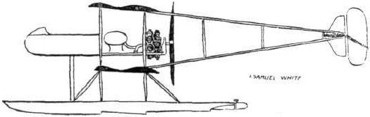
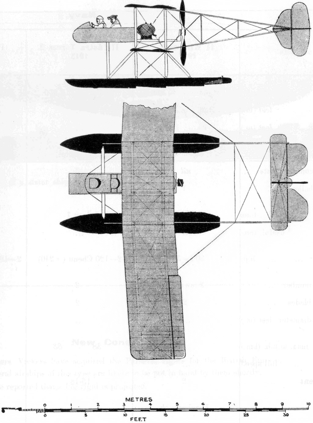
Wight Double-camber No. 1 Seaplane
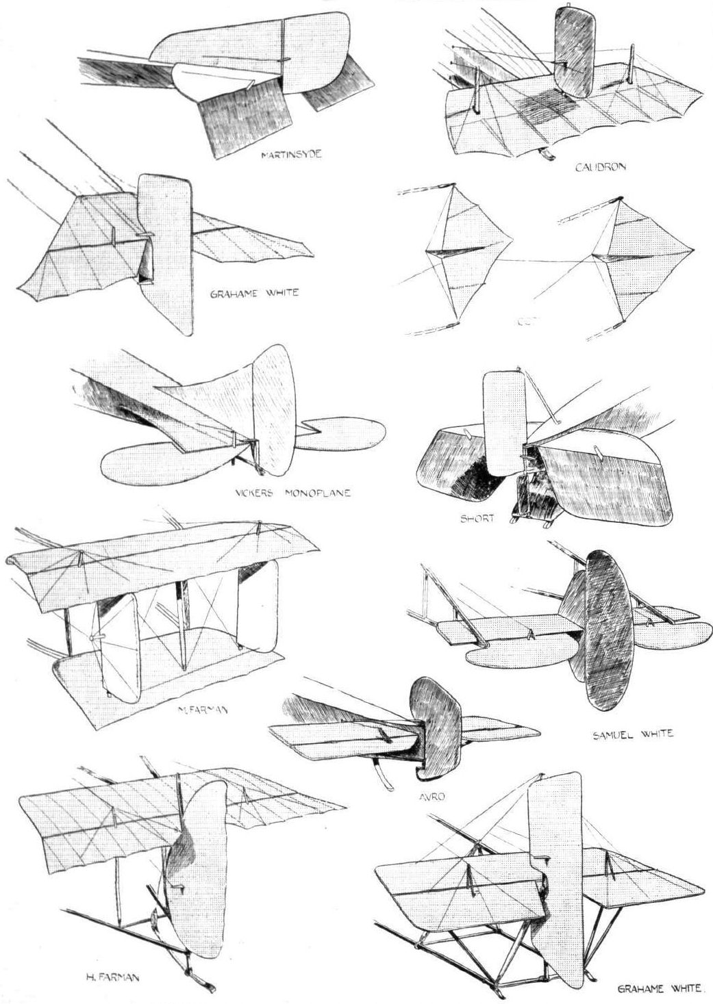
During 1912 Howard T. Wright joined J. Samuel White and Co., of East Cowes, Isle of Wight, and his first design for them was the Mo. 1 Seaplane, which appeared in 1913. The machine was a conventional pusher mounted on twin floats, and seated two in tandem in the nacelle. Its unusual feature was the designer's original wing section with a "double-camber". Ailerons of the Curtiss type were fitted between the wings, and the engine was the two-row 160 h.p. Gnome.
Показать полностью
M.Goodall, A.Tagg British Aircraft before the Great War (Schiffer)
Deleted by request of (c)Schiffer Publishing
J. SAMUEL WHITE & Co. Ltd. (East Cowes, Isle of Wight)
This old established shipbuilding company appointed Howard T. Wright as manager and chief designer of their Aviation Dept. in November 1912, and he immediately began the design of their first type. This was a seaplane and although some landplanes were built, the company concentrated principally on seagoing aircraft, mainly for the Admiralty under the Wight name.
WIGHT No.I seaplane
This aircraft was built with some urgency, in order to appear at the Aero Show at Olympia opening on 14 February 1913. There was insufficient time and the machine was incomplete when displayed. After the Show it was returned to Cowes and was completed in the following May.
On the thirteenth of May Howard Wright attempted his first flight as a seaplane pilot, but crashed on takeoff. The remains were rebuilt with some minor changes.
The rebuilt machine was ready on 10 July 1913 and F.P. Raynham was the pilot, but was also involved in an accident causing less damage. The machine was again rebuilt, but this time greater changes were made, resulting in a change of identity to No.2.
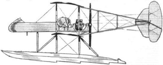
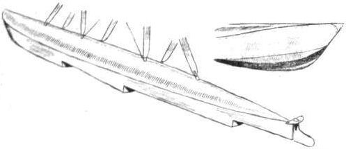
Wight No. 1 was a two-seat pusher biplane, with the nacelle mounted in the gap and carrying its tail unit on booms, which tapered to a point at the tail in elevation, but were parallel in plan. The machine was built with a broad center section, the outboard ends of which were connected by pairs of interplane struts, which continued below to the floats. These struts were only part of the complex of struts, connected to the center section and nacelle, which comprised the chassis for the long narrow floats with three steps.
The two bay wings, outboard of the center section, were slightly swept back and the top wing had greater span by a small amount. The ailerons were mounted on the interplane struts at midgap. The wings had an aerofoil section incorporating 'double camber', covered under patent No.24822/1912, which aimed to improve lift, but not without a penalty, for drag was increased. The tailplane fitted inside the vee of the booms and overhung slightly each side.
The elevator was divided by a tall rudder of symmetrical shape, hinged to the fin, which also extended symmetrically above and below the tailplane.
The nacelle was an elongated enclosure of shallow depth, with the pilot in front, protected by a raised decking; the passenger behind was unprotected, and both crew were rather exposed by the low cockpit sides. The engine at the rear was completely exposed, as was the forty gallon fuel and fourteen gallon oil tanks just behind the crew.
Neither the first nor rebuilt second version was acquired by the Admiralty.
Data:
Span top 44ft
Span bottom 40ft
Chord top 6ft 6in
Chord bottom 5ft 6in
Area 500 sq. ft
Length 30ft
Height 10ft
Floats 21ft long by 2ft 6in beam
Weight 1,350lb.
Weight allup 2,000lb.
Speed 70 mph
Price ?2,500
Показать полностью
Журнал Flight
February 8, 1913.
WHAT THERE WILL BE TO SEE AT OLYMPIA.
THE MACHINES.
Messrs. J. Samuel White and Co., Ltd.
On the stand of this famous firm of Government contractors and shipbuilders, who have lately opened an aviation department under the control of Mr. Howard T. Wright, will be shown a two-seater hydro-biplane driven by a 160-h.p. Gnome motor. From our silhouette it will be seen that this interesting machine is devised somewhat on Farman lines. Unlike that machine, however, its main planes are of a special design, patented by Mr. Howard Wright, and are arranged at a slight dihedral angle. The planes are retarded and have negative tips, while double-acting ailerons are employed to correct lateral roll. The main feature of the special type of aerofoil that is used on this machine is that it gives a wide speed range, and that its centre of pressure does not vary more than two per cent, for angles of incidence between such a wide range as 3° and 15°. The machine is supported on two floats, built in accordance with Messrs. J. S. White & Co.'s patents covering their construction and design. Each has three steps, and each is provided with a rudder at the rear extremity, so that the machine may be easily guided over the surface of the water. The weight of the machine fully loaded is 2,000 lbs., and it has a supporting area of 500 sq. ft. It has been designed to have a speed range of from 34 to 70 miles an hour. A non-lifting tail is used, supported by triangular outriggers.
Flight, February 22, 1913.
SOME MORE AEROPLANES AT OLYMPIA.
J. SAMUEL WHITE AND CO.
On their stand, to the left of the main entrance, this firm is showing a high-powered hydro-biplane. Unfortunately, through a lack of sufficient space, it was found impossible to assemble the whole machine. However, although the outer sections of the planes are not fitted, quite a good idea of the machine as it appears when in flying trim, can be gathered from wash drawings that are shown on the stand. This hydro-biplane has been built to the designs of Mr. Howard T. Wright, who, as most people interested in aviation know, is in charge of the aeronautical department of the above well-known firm of naval Government contractors. He has devised and constructed a machine which he claims will have a speed range of from 30 to 70 miles an hour, which will be capable of alighting on and starting off from rough water, and which will be easy to fly.
Wing construction. - The most notable point regarding the wing construction is the original cross-section that is employed. On the under-surface of the planes there is a single camber, but on the top surface two distinct cambers are noticeable. Mr. Howard T. Wright has taken out patents on this particular aerofoil cross-section, and, it having been tested by Eiffel in Paris, it has been found to give an exceptionally wide speed range. Further, it has the property that the location of its centre of pressure travels but little for wide variations in the angle of incidence. At its maximum speed, the planes are designed and adjusted so that they will fly at a slight negative angle. At the lowest speed, 30 miles an hour, they fly positively incident to the wind at 15. The planes are built about two main spars, which arc of box cross-section and which have spruce sides and elm strips top and bottom. Where struts are carried to the spars, and where the alighting gear is attached, the hollow spars are cored with solid elm. Most of the ribs which give the shape to the plane are of I-section spruce.
Sixteen struts of spruce separate the planes, the eight centre ones being solid, while the remainder are of hollow construction. Compensating ailerons are used for balancing.
Float construction. - The machine rests on the water on two long torpedo-shaped floats, built according to Messrs. J. Samuel White's patents covering their design and method of construction. They each have three steps, the two forward ones being arranged immediately below the two vertical struts that take the main weight of the machine. On the under side they are convex, a shape which makes them particularly suitable for open-sea work. Their interior construction is mostly of three-ply wood and elm, while they are covered with very fine three-ply cedar, a selection of materials which gives enormous strength with quite light weight. Although these floats are of considerable size they only weigh 100 lbs. each complete with their fittings.
The body, which proceeds forward from the main plane, so that the occupants may have a good clear view all around them, is a lattice girder of the usual type with elm longitudinal members and spruce cross pieces, covered with fabric. It seats two persons in tandem, the pilot taking the front seat where he controls the machine by means of a vertical universally jointed lever for fore and aft attitude and balancing, and a foot-bar for the rudder. The big 160-h.p. rotary Gnome motor is mounted between two heavy flanged Steel plates at the rear end of the body, and drives a large diameter Chauviere propeller with armoured tips. Fuel is stored in a large 40-gallon tank, from which the petrol and oil feed down to the engine by gravity.
The tail, supported by a pair of triangular outriggers, carries vertical and horizontal fixed stabilising surfaces, two elevator flaps, and an unbalanced rudder.
Показать полностью