J.Wegg General Dynamics Aircraft and Their Predecessors Since 1912 (Putnam)
T-2
The first design by B Douglas Thomas for Thomas Brothers was based on the Model J he had designed for Curtiss. Work started at Bath then moved to Ithaca, New York, on 7 December, 1914, and the first flight was made soon after arrival there. Powered by a 90hp Austro-Daimler, the T-2 had two-bay wings and was rated as the best performing aircraft of its day achieving a maximum speed of 83mph and climbing with one passenger and a 1,000 lb payload to 3,800ft in ten minutes.
A British purchasing commission tested it and placed orders for twenty four for the RNAS in 1915 in two batches of twelve (3809-3820, 8269-8280) powered by 90hp Curtiss OX-5 engines. Reportedly, there were no additional orders because of a growing shortage of the Curtiss OX.
A single main float development with a three-bay wing and enlarged fin and rudder was the SH-4 of which fifteen were ordered by the Navy (A-134/136, 395/406) in 1916.
Span 36ft; length 26ft; wing area 350sq ft.
Weight empty 1,075 lb; gross weight 1,972 lb.
Maximum speed 83mph; climb with full load 3,800ft/10 min.
Показать полностью
O.Thetford British Naval Aircraft since 1912 (Putnam)
THOMAS T.2
This two-seat biplane was produced by the Thomas Bros. Aeroplane Company of the USA and designed by an Englishman, B D Thomas, who bore no relationship to the American proprietors. Twenty-four were ordered by the Admiralty for the RNAS in 1915; they were in two batches of 12 numbered 3809 to 3820 and 8269 to 8280. One 90 hp Curtiss OX-5 engine. Maximum speed, 83 mph. Climb, 10 min to 3.800 ft.
Показать полностью
Jane's All The World Aircraft 1919
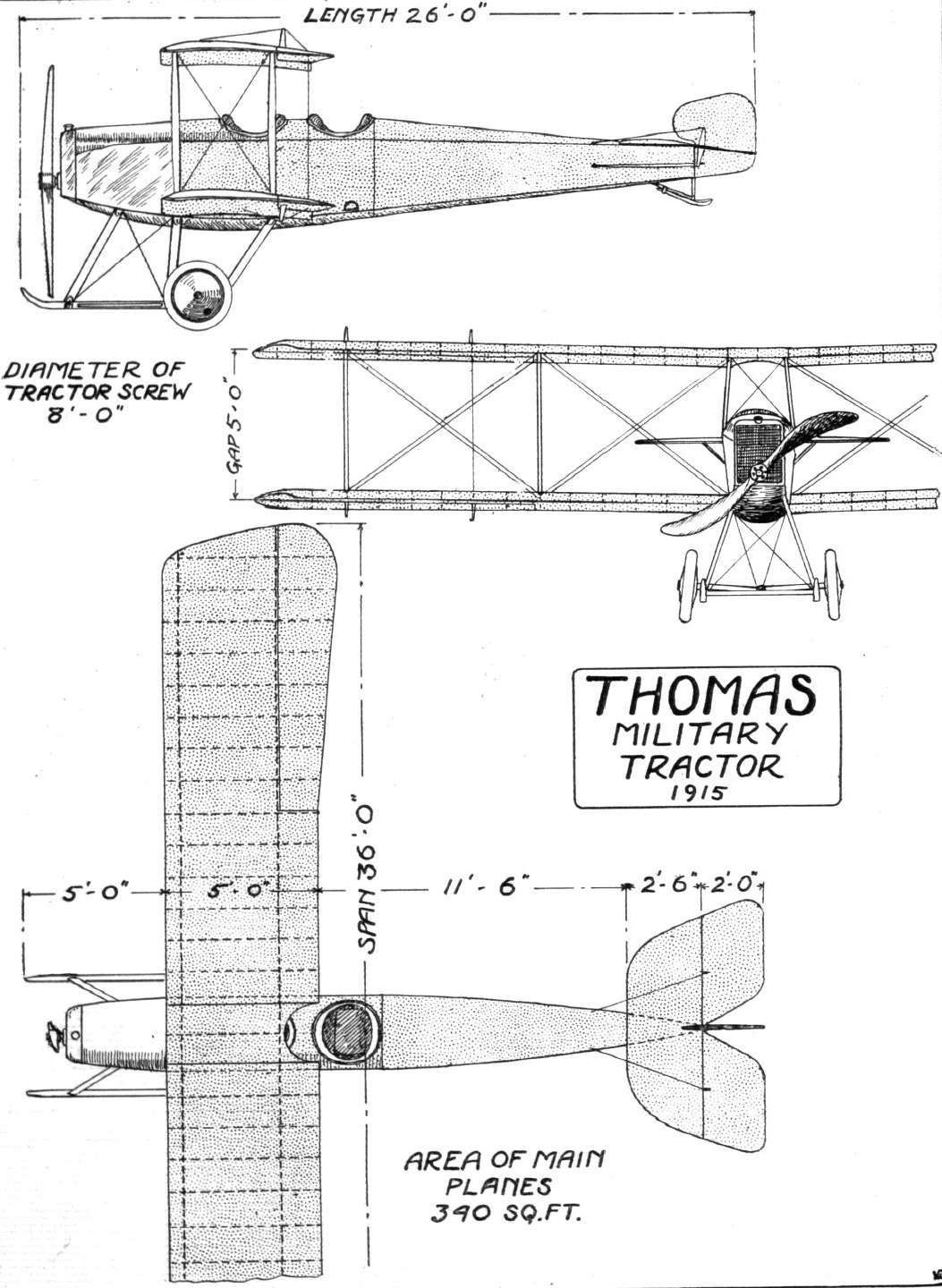
THOMAS MILITARY TRACTOR, Type T2. 80-90 horse power.
1. Minimum head resistance and maximum efficiency. Especially adapted to all-round military work-scouting, reconnaissance, range spotting, messenger service, etc
2. Carries pilot and observer, fuel for four hours, and 285 lbs. (130 kgs.) additional (total useful load is 897 lbs. (405 kgs.) Speed range is 38-82 m.p.h. (60-130 km) Weight (empty) is 1075 lbs. (437 kgs.) Climb with full load is 4,000 feet (1,220 m.) in 10 minutes, 800 feet (245 m.) in first minute.
3. Overall length, 28 feet (8 50 m,), span, 36 feet (11.00 m.), chord, 5 feet (1.50 m), gap. 5 feet (1.50 m.) wing area, 350 sq. feet (33 m2), loading, 5.3 lbs. sq. feet.
4. Entirely new model, developed for military purposes,
Показать полностью
Журнал Flight
Flight, April 23, 1915.
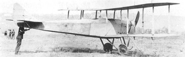
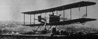
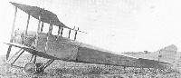
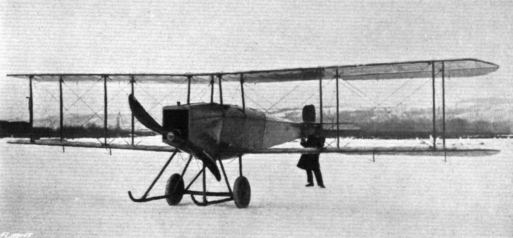
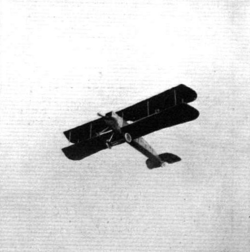
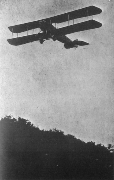
THE THOMAS MILITARY BIPLANE.
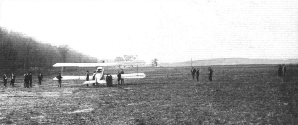
ONE of the several new American machines which have recently been produced, is the tractor biplane, shown in the accompanying illustrations, designed and constructed by Messrs. Thomas Brothers, of Ithaca, N.Y., with a view to meeting the requirements of the U.S. military authorities. Nothing very startling is claimed for this new biplane by its designers, but it is a sound serviceable machine, built on what might be termed standard lines, and incorporating in its construction many novel features. Briefly the Thomas military tractor is a two-seater biplane with a fuselage of good streamline form, and fitted with a stationary engine - in the case of the test machines we believe the engine was a 90 h.p. Austro-Daimler. The over-all length is 26 ft., the span 36 ft., chord 5 ft., gap 5 ft.; weight, empty, 1,075 lbs.
During the test flights the following results were obtained:-
U.S. Army Requirements. Result of Tests.
Speed 70 m.p.h. 81.1 m.p.h.
Useful load 750 lbs. 800 lbs.
Climb fully 4,000 ft. in 10 mins. 1800 ft. in first min.
loaded 14,000 ft. in 10 mins.
Slow speed 40 m.p.h. 38m.p.h.
Propeller efficiency 70 per cent. 75 per cent.
The full load consisted of pilot, two passengers, and four hours' fuel.
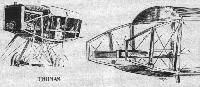
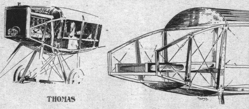
As regards constructional details, the fuselage, which is of rectangular section in front, gradually tapering to a section, having its sides sloping inwards, counting from top to bottom, is built up of ash longerons connected with spruce struts. Both longerons and struts are lightened by being milled out to an I section, and are connected by means of steel plates bolted to the longerons in such a manner that the bolts pass through the neutral axis of these members.
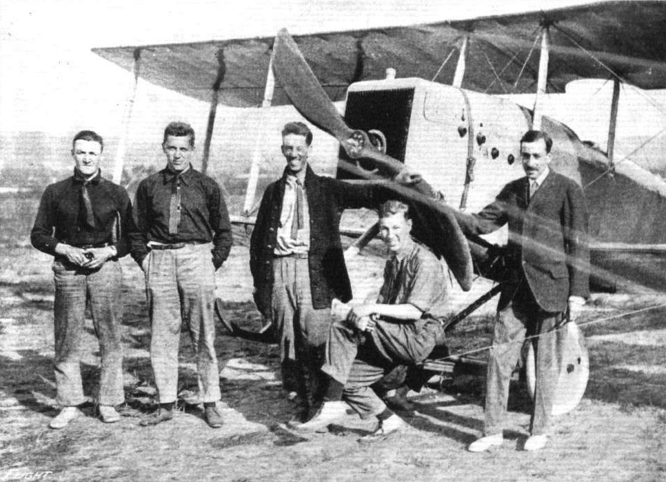
In the extreme nose of the fuselage is the engine, mounted on two very stout ash bearers, which are in turn carried on two transverse members of the fuselage. Immediately in front of the engine is mounted the radiator, which is provided with an opening through which passes the propeller shaft. Behind the engine is a transverse panel, to which is secured the petrol service tank, whence fuel is fed to the engine by gravity. A larger tank containing 20 gallons of petrol rests on the lower longerons, and above this main tank is placed the observer's seat. As the fuel in the service tank is consumed, it is replenished from the main tank by means of a hand-operated pump placed in the pilot's cockpit.
To the rear of the observer's seat is a second transverse panel, which serves as an instrument board, with the following instruments let in, so that the dials are flush with the board: Petrol pressure gauge. "Tel" revolution indicator, inclinometer, clock, barograph, air speed indicator, switch, petrol cut-off cock and spark advance lever. The controls in front of the pilot are of the wheel and column type, the wheel operating the rudder, whilst a to-and-fro movement actuates the elevator. Lateral control is at present effected by means of a shoulder yoke operating through flexible cables the double acting ailerons, but if desired a more orthodox form of lateral control can be substituted. A turtle back, formed in front by the aluminium bonnet over the engine and in the rear by stringers covered by fabric, tops the fuselage, which is also provided with a curved "belly" formed in the same manner as the turtle back.
In front the fuselage is enclosed in a covering of light gauge sheet metal, whilst the rear part is covered in the usual way with fabric.
The tail planes, which are built up entirely of steel tubing, consist of the usual members, i.e., a flat, non-lifting stabilising plane - to which the elevator is hinged - and of a partly balanced rudder. A small skid mounted on a continuation of the rudder post protects the tail planes against contact with the ground.
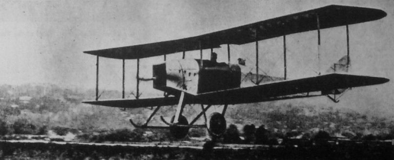
A chassis of the wheel and skid type takes the weight of the machine when on the ground. The two ash skids are carried on six chassis struts of the same wood coming down from the lower longerons of the fuselage. The first pair of these struts are attached to the fuselage approximately under the centre of the engine, and the second pair run to the point where the rear engine bearer is secured to the fuselage. The rear pair of struts are attached to the fuselage longitudinals at the point where these meet the rear spars of the lower main plane. The stub axles are secured at their inner ends by a pin passing through the two transverse chassis members connecting the skids and between which the axles work. Rubber shock absorbers passing round the axles and secured to the skids provide the necessary springing. Cross wiring of the chassis is effected by stranded cables of ample proportions. The two disc wheels are of 26 ins. diameter, and fitted with 4 in. tyres.
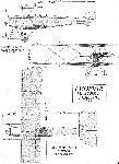
In plan view the main planes are of a form that is rapidly becoming popular with a number of aeroplane designers both in this and other countries, that is to say having their trailing edge slightly longer than the leading edge, a form which is generally considered to minimize end losses. Both upper and lower planes are built in right and left hand pairs, the two halves of the upper plane being attached to a centre section mounted on four short struts coming from the upper longitudinals of the body. In order to give a better view in an upward direction, the trailing edge of this centre section has been cut away.
The wings are built up of silver spruce spars, milled out to an I section, except where are attached the interplane struts. The ribs are also of I section, having thin spruce webs and being fitted with flanges. At the point of attachment of the interplane struts the ribs are of the box type.
All the internal wood-work is painted with a water-proof preparation. The various bays in the wings are internally cross braced with solid steel wire. It is stated by the designers that the factor of safety is nowhere less than 7, which figure is exceeded in many places. Double acting ailerons are hinged to both upper and lower planes, so that there should be ample lateral control. In order to render the ailerons still more effective, their trailing edge projects some little distance behind that of the main planes.
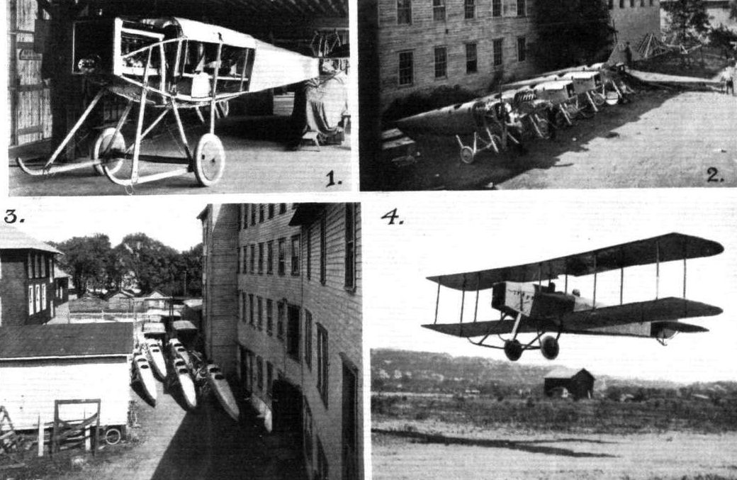
Special attention has been given to demountability and accessibility of all important parts. Such fittings as wing stay fastenings and strut connections can be very quickly assembled and again taken down.
At their new works at Ithaca, N.Y., to which locality they moved some little time ago, Messrs. Thomas Brothers have facilities for turning out machines at a rate to satisfy Government demands, and on Lake Cayuga a 40-miles stretch of water is available for testing waterplanes, of which this firm have produced several types, while adjoining the lake is a good size aerodrome, where the land machines are put through their trials.
Показать полностью