Описание
Страна: Россия
Год: 1915
Варианты
- Сикорский - Илья Муромец - 1913 - Россия
- Сикорский - Илья Муромец поплавковый - 1914 - Россия
- Сикорский - Илья Муромец серии Б - 1914 - Россия
- Сикорский - Илья Муромец серии В - 1915 - Россия
- Сикорский - Илья Муромец серии Г - 1915 - Россия
- Сикорский - Илья Муромец серии Д - 1916 - Россия
- Сикорский - Илья Муромец серии Е - 1916 - Россия
- М.Маслов Русские самолеты Первой Мировой (Эксмо)
- В.Шавров История конструкций самолетов в СССР до 1938 г.
- В.Кондратьев Самолеты первой мировой войны
- А.Шепс Самолеты Первой мировой войны. Страны Антанты
- H.Nowarra, G.Duval Russian Civil and Military Aircraft 1884-1969
- A.Durkota, T.Darcey, V.Kulikov The Imperial Russian Air Service (Flying Machines)
-

A.Durkota, T.Darcey, V.Kulikov - The Imperial Russian Air Service /Flying Machines/
Sikorsky Il'ya Muromets Type V (S.23 series, ship #2).
-

D.Mechin - Foreign Fronts of the French Air Force 1914-1919 /Aeronaut/
Ilya Murometz type V no 10 commanded by Poruchik (lieutenant) A. M. Konstenchik and on which served Feldwebel (sergeant-major) Marcel Plat, making on April 8, 2, 3 and 26, 1916 three flights on board the aircraft whose precise registration possibly painted on the fuselage is not known.
-
А.Шепс - Самолеты Первой мировой войны. Страны Антанты
Дальний разведчик/бомбардировщик С-23 "Илья Муромец" тип В N 150 Эскадры воздушных кораблей (1914г.)
-
-

М.Маслов - Русские самолеты Первой Мировой /Эксмо/
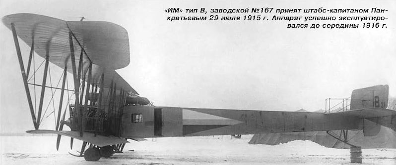
«ИМ» тип В, заводской №167 принят штабс-капитаном Панкратьевым 29 июля 1915 г. Аппарат успешно эксплуатировался до середины 1916 г.
-
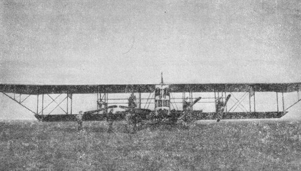
М.Маслов - Русские самолеты Первой Мировой /Эксмо/
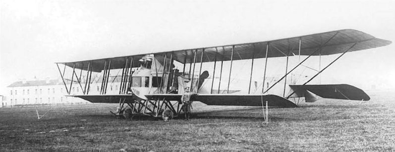
Воздушный корабль «Илья Муромец» серии В на аэродроме в Старой Яблонне под Варшавой летом 1915 г.
-
М.Маслов - Русские самолеты Первой Мировой /Эксмо/
«ИМ» тип В, предположительно заводской №150, на якорной стоянке в Старой Яблонне летом 1915 г.
-
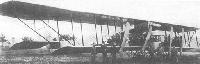
В.Кондратьев - Самолеты первой мировой войны
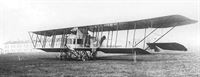
"Илья Муромец В" в полете, весна 1915г.
The Il'ya Muromets Korabley Kievskiy the first flying over Yablonna in 1915. Bashko was deputy commander and later commander of this aircraft, which was a type 'B' or 'Veh.' It was equipped with four Argus engines; two were 125hp and two were 140hp. These were the same engines used on the machine Igor Sikorsky flew from St. Petersburg to Kiev. That plane was a type '6' or 'Beh,' and also was named Kievskiy. -
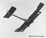
М.Маслов - Русские самолеты Первой Мировой /Эксмо/
«ИМ» №150 в воздухе
-
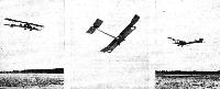
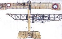
Журнал - Flight за 1919 г.
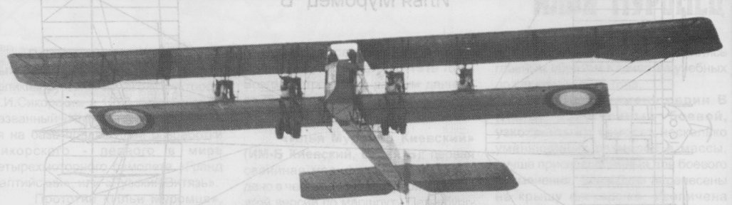
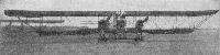
Three views of a four-engined Sikorsky biplane in flight
-

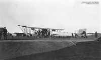
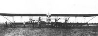
A.Durkota, T.Darcey, V.Kulikov - The Imperial Russian Air Service /Flying Machines/
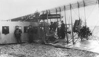
The V-nosed IM-2, with its Sunbeam engines. The location is possibly Yablonna, shortly after testing the new motors in June, 1915, but may also be either Bialystok or Lida in late July, 1915, after the retreat from the Polish salient. The occasion is unknown, but appears to be an inspection of some importance due to the size of the crowd gathered.
-

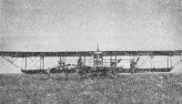
A.Durkota, T.Darcey, V.Kulikov - The Imperial Russian Air Service /Flying Machines/
The Kievskiy after its return from the mission of March 31, 1915, over East Prussia. On this flight, the crew photographed enemy troop positions to verify information received by the Russian 1st Army. The information was proven false.
-

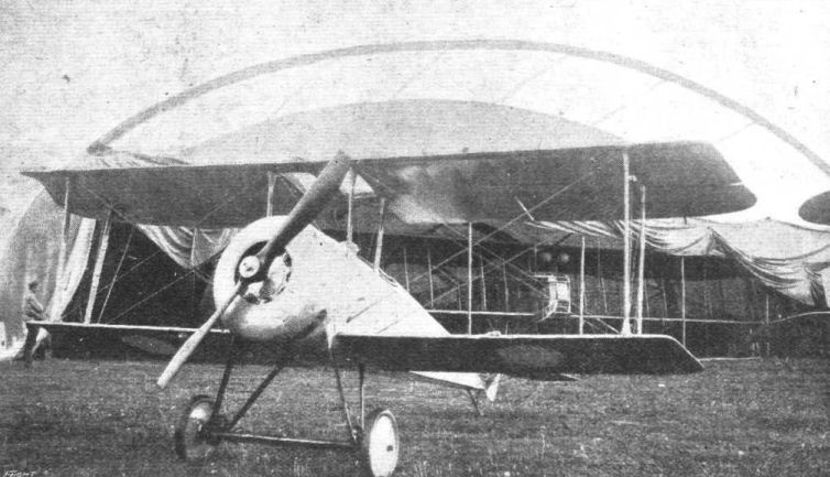
Журнал - Flight за 1918 г.
THE SIKORSKY SCOUT. - Three-quarter front view of this machine fitted with 110 h.p. Le Rhone engine.
An S-20 shown at the front in late 1916 Directly behind the S-20 is a large portable cloth hangar; extending out is the nose of an Il'ya Muromets bomber (type "V").Другие самолёты на фотографии: Сикорский С-20 - Россия - 1916
-
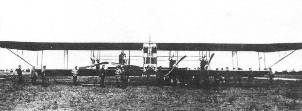
M.Schmeelke - Zeppelin-Lindau Aircraft of WW1 /Centennial Perspective/ (42)
The first "giant aircraft" were built by Igor Sikorski in Russia in 1913.
-
В.Шавров - История конструкций самолетов в СССР до 1938 г.
Самолет "Илья Муромец" серии В с ("корабль Киевский")
-

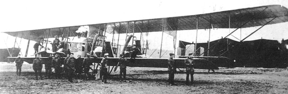
A.Durkota, T.Darcey, V.Kulikov - The Imperial Russian Air Service /Flying Machines/
The Il'ya Muromets (Ship 1) with crew members of the EVK, based at Yablonna, near Warsaw, 1915.
-

A.Durkota, T.Darcey, V.Kulikov - The Imperial Russian Air Service /Flying Machines/
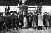
The Il'ya Muromets II, at Lida, July 1915, on the occasion of testing the dummy 25-pud (880 lb.) bomb. From left to right in the front are R-BVZ engineer Kireyev, Stabs-Kapitan Nikolsky (deputy commander of the IM-2), Igor Sikorsky, and Stabs-Kapitan Pankrat'yev. General-Maior Shidlovsky, commander of the EVK, is to the right of the bomb, with long dark overcoat and white beard. The port inboard 150hp R-BVZ-6 engine has the Hazet radiator, while the starboard inboard engine and the two outboard engines still have the Salmson box-type radiator.
-
Журнал - Flight за 1919 г.
A 1,000-lb. bomb in front of a Sikorsky biplane
-

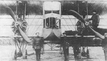
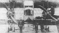
A.Durkota, T.Darcey, V.Kulikov - The Imperial Russian Air Service /Flying Machines/
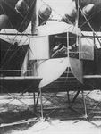
An Il'ya Muromets (type V), shows two of its four Argus engines. The flat glassed nose of the V type distinguished it from the earlier type B and Kievskiy models.
-

A.Durkota, T.Darcey, V.Kulikov - The Imperial Russian Air Service /Flying Machines/
Standing in front of the blunt-nosed type 'Veh' Kievskiy at the Kresty Farming School, near Pskov, September 1915, are left to right, Serednitskiy (deputy commander). Kapitan Bashko (commander). Poruchik Lavrov (mechanic), and Constantin N. Finne, the EVK's senior physician. Bashko and his crew soon left this location and became members of the Second Muromets Detachment at Zegewold, east of Riga. If this machine is a Kievskiy, it appears to be a later model 'Veh,' because of the different nose. This aircraft was actually the third Klevskly and most likely used the Argus engines salvaged from the Kievskiy which crashed July 19, 1915.
-

A.Durkota, T.Darcey, V.Kulikov - The Imperial Russian Air Service /Flying Machines/
The Kievskiy while at Yablonna, spring 1915, being inspected by Major-General Shidlovsky (bearded officer, third from right), commander of the EVK. Notice the v-shaped nose of the Kievskiy, the first 'Veh' model. It allowed the pilot much greater visibility.
-

A.Durkota, T.Darcey, V.Kulikov - The Imperial Russian Air Service /Flying Machines/
The Il'ya Muromets "Kievskiy" at Yablonna, near Warsaw, in 1915.
-
H.Nowarra, G.Duval - Russian Civil and Military Aircraft 1884-1969
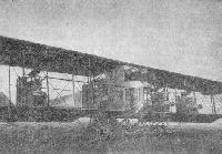
Sleeping giant - an ‘Ilya Muromets’ with canvas covers over engines and propellers.
-

A.Durkota, T.Darcey, V.Kulikov - The Imperial Russian Air Service /Flying Machines/
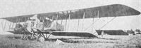
Il'ya Muromets type V (serial no. 21), 1915. This machine is equipped with four 150hp R-BVZ engines.
-

G.Haddow, P.Grosz - The German Giants /Putnam/
Sikorsky I.M. V, one of several aircraft that bore the name "Kievsky". Igor Sikorsky is seen second from the right.
-
В.Шавров - История конструкций самолетов в СССР до 1938 г.
Самолет "Илья Муромец" серии В с двигателями РБЗ-6 с подвешенной 25-пудовой бомбой
-

A.Durkota, T.Darcey, V.Kulikov - The Imperial Russian Air Service /Flying Machines/
The Il'ya Muromets II, factory number 167. This machine was a blunt-nosed type 'Veh' and is seen here in July, 1915, being fitted with the R-BVZ-6 150hp engines. These engines increased the speed of the Il'ya Muromets to 75 mph and the ceiling to more than 9750 feet. Salmson box-type radiators have been fitted to three engines, as seen on the starboard inboard motor, while one engine was equipped with the Hazet radiator. When this aircraft was stationed in Pskov in August, 1915, the three Salmson radiators were replaced by the Hazet model, which not only gave better streamlining, but was also easier and simpler to install and maintain. The starboard outboard engine shows the R-BVZ logo cast into the underside of its block.
-

A.Durkota, T.Darcey, V.Kulikov - The Imperial Russian Air Service /Flying Machines/
«ИМ» №167 в июле 1916 г. при отправке в тыл. На борту надпись, свидетельствующая о боевых успехах: «Воздушный корабль Илья Муромец 2-й. Налетал около 10 000 верст, сброшено 300 бомб, общим весом до 400 пудов»
The crew of the IM-2, with the fuselage on a flat car. Left to right are, Poruchik Smirnov, temporarily assigned; Stabs-Kapitan Pankrat'yev, commander; Stabs-Kapitan Nikolsky, deputy commander; Poruchik Federov, military pilot; and Poruchik Pavlov, military pilot and gunner, Date and location unknown, although the aircraft is most likely a type 'Veh.' -

A.Durkota, T.Darcey, V.Kulikov - The Imperial Russian Air Service /Flying Machines/
Bombs being loaded onto an Il'ya Muromets. Depending on fuel and defensive armament loads, the bomb load of an Il'ya Muromets varied between 1,150 and 2,200 pounds. The upper machine gun position is visible near the fuel tanks.
-
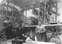
М.Маслов - Русские самолеты Первой Мировой /Эксмо/
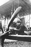
Ремонт двигателя «Аргус» на «ИМ» №150 ведет механик Лавров
-
М.Маслов - Русские самолеты Первой Мировой /Эксмо/
Монтаж двигателей РБВЗ-6 в Старой Яблонне на «ИМ» №167
-

A.Durkota, T.Darcey, V.Kulikov - The Imperial Russian Air Service /Flying Machines/
Pankrat'yev standing on the far left, in front of his Sunbeam-powered IM-2. His deputy commander, Stabs-Kapitan Sergei N. Nikolsky, is standing fifth from the left, next to the woman wearing the light-colored jacket. This machine was the early type 'Veh' with a V-nose. With the four 150 hp Sunbeam motors, performance was slightly improved over that of the Salmson engines. The top speed was 62 to 69 mph and the endurance was about 4 1/2 to 5 hours, providing a range of about 275 miles. The ceiling was improved, up to 9000 feet, but was not up to the standards of the Argus-powered Muromets. The large car-type frontal radiators created excessive drag.
-
-

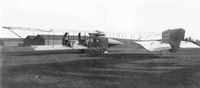
A.Durkota, T.Darcey, V.Kulikov - The Imperial Russian Air Service /Flying Machines/
A type V equipped with four 150hp Sunbeam engines. The Cyrillic letter Б (Beh) is pronounced like the English letter B and denotes a type "B" aircraft. The Cyrillic letter B (Veh) is pronounced like the English letter V and denotes a type "V" aircraft.
-

A.Durkota, T.Darcey, V.Kulikov - The Imperial Russian Air Service /Flying Machines/
Il'ya Muromets type V (serial no. 19), summer 1915. The Russian letter B (shown on the rudder) is pronounced as "Veh." Thus this type is referred to as a type "Veh."
-

A.Durkota, T.Darcey, V.Kulikov - The Imperial Russian Air Service /Flying Machines/
Officers of the EVK, including many ship commanders, at Lida, July, 1915. From left to right are mechanic Sirotin; Starshi Leitenant (Naval Lieutenant) G.I. Lavrov, commander IM-1; Stabs-Kapitan A.V. Pankrat'yev, commander IM-2; Poruchik G.V. Alekhnovich, Commander IM-5; Stabs-Kapitan Chechulin; Poruchik A.V. Konstenchik, deputy commander IM-5, later commander IM-10; Poruchik Krzhichkovskiy; Poruchik Lukinskiy; mechanic Kisel, official assigned to the IM-5; Stabs-Rotmistre A.V. Serednitskiy, later commander IM-18; Igor Sikorsky; and Poruchik Loiko, deputy commander IM-5. Behind them is a Sunbeam-powered Muromets.
-
-

A.Durkota, T.Darcey, V.Kulikov - The Imperial Russian Air Service /Flying Machines/
Grand Duke Alexander Mikhailovich (second from right), was appointed by Nicholas II to head Russian military aviation in World War One. The grand duke is pictured here inspecting the Il'ya Muromets (ship No.1) at Yablonna in 1915. To the left of the grand duke is General M. V. Shidlovskiy, commander of the EVK.
-
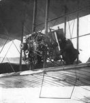
М.Маслов - Русские самолеты Первой Мировой /Эксмо/
Опробывание двигателей «Сальмсон». Примерно так механик мог проделать операцию по обслуживанию двигателя в полете. Видны специальные поручни между стойками крыльев, за которые следовало держаться, выходя на крыло
-
М.Маслов - Русские самолеты Первой Мировой /Эксмо/
Двигатель «Сальмсон» на «ИМ» №143. В полете вырвало один цилиндр, который повредил крыло
-
В.Шавров - История конструкций самолетов в СССР до 1938 г.
Самолет "Илья Муромец" серии В учебный с двумя двигателями "Санбим" по 225 л. с. с тянущими винтами
-

A.Durkota, T.Darcey, V.Kulikov - The Imperial Russian Air Service /Flying Machines/
An Il'ya Muromets type V (ship No.6), equipped with two Salmson engines, was used as a trainer. This particular machine was destroyed in a training flight at Yablonna in February 1915.
Early Spring IM-6 still on skis -
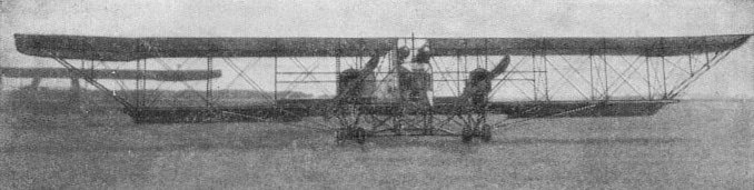
М.Маслов - Русские самолеты Первой Мировой /Эксмо/
«ИМ» тип В №157, оснащенный двумя двигателями «Сальмсон» с толкающими воздушными винтами на аэродроме в городе Лида
-

A.Durkota, T.Darcey, V.Kulikov - The Imperial Russian Air Service /Flying Machines/
The IM-2 loaded on a flat car ready for transport. The location is possibly Zegevold, December, 1915, when Pankrat'yev and his crew were transferred to the Galician Front as part of the First Muromets Combat Detachment. Pankrat'yev is on the far left, against the flat car, while his deputy commander, Stabs-Kapitan Nikolsky, is second from the right with the bandaged head.
-
М.Маслов - Русские самолеты Первой Мировой /Эксмо/
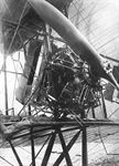
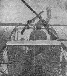
Носовая часть «остроносого» «ИМ» №150 с открытыми передними стеклами. За штурвалом капитан Горшков, впереди видна рамка для прицеливания при бомбометании
-

A.Durkota, T.Darcey, V.Kulikov - The Imperial Russian Air Service /Flying Machines/
The Kievskiy's glazed flooring, illustrated in this photograph, gave the ship's pilot a great advantage in navigating.
-

М.Маслов - Русские самолеты Первой Мировой /Эксмо/
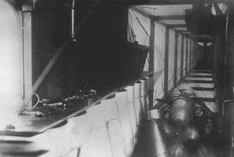
Бомбовый груз на «ИМ» №150 в виде штатного вооружения в специальной кассете по правому борту фюзеляжа. Дополнительные бомбы сложены и увязаны в центре салона. Темные пятна в правой верхней части снимка не что иное, как подвешенные шлемы экипажа
-

A.Durkota, T.Darcey, V.Kulikov - The Imperial Russian Air Service /Flying Machines/
The interior of the Muromets, showing the bomb racks on the left and the straps for fastening the bombs lying on the floor. Secured to the right is a Moisin-Nagant carbine. Its caliber was 7.62mm and it had a magazine of five rounds. This type of rifle and a Madsen light machine gun were the only weapons on board the Kievskiy when it was attacked by three enemy aircraft on July 19, 1915.
-
В.Шавров - История конструкций самолетов в СССР до 1938 г.
Стрелковая установка в центроплане на "Муромцах" серии В. На переднем лонжероне пулемет "Люис", на заднем - ружье-пулемет " Мадсен"
-

A.Durkota, T.Darcey, V.Kulikov - The Imperial Russian Air Service /Flying Machines/
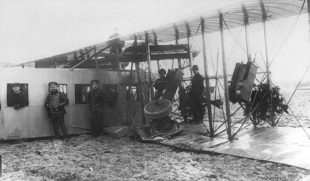
An unknown gunner demonstrating the upper gun position on an Il'ya Muromets. This was Pliat's station when the IM-10 was hit by antiaircraft fire over Daudzevas.
-

A.Durkota, T.Darcey, V.Kulikov - The Imperial Russian Air Service /Flying Machines/
The IM-10 after its emergency landing from the mission over Daudzevas, April 26, 1916.
-
М.Маслов - Русские самолеты Первой Мировой /Эксмо/
В результате грубой посадки этот «ИМ» №143 поручика Алехновича снес шасси
-

М.Маслов - Русские самолеты Первой Мировой /Эксмо/
Авария «ИМ» №137 поручика Головина в Старой Яблонне 30 апреля 1915 г.
-
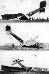
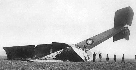
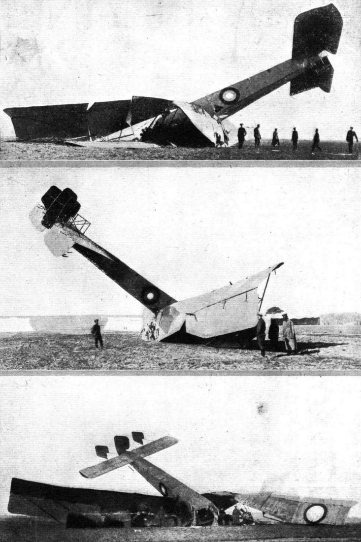
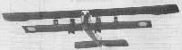
Журнал - Flight за 1919 г.
Three views of one of the early Sikorsky biplanes, fitted with two 250 h.p. Salmson engines, which side-slipped from about 20 metres during the retreat from Warsaw
-

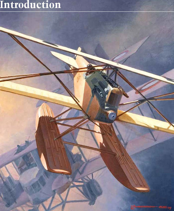
J.Herris - German Seaplane Fighters of WWI /Centennial Perspective/ (2)
Lt. d.RMi Fritz Hammer, flying the KDW prototype, Marine Number 748, from the German naval air station at Angernsee, downs a Russian four-engine Sikorski Il'ya Mouromets reconnaissance-bomber on 23 September 1916. Sikorski IM-6 crash-landed at its base with 293 bullet holes and three of its four crewmen wounded. This was one of only three air-to-air victories scored over these tough bombers during the war.
Другие самолёты на фотографии: Hansa-Brandenburg KDW - Германия - 1916
-

A.Durkota, T.Darcey, V.Kulikov - The Imperial Russian Air Service /Flying Machines/
Based on the "V" type Il'ya Muromets, the cabin was divided into the pilot's cabin and the observer-artillery cabin. The pilot's cabin contained the pilot's seat, the copilot's seat, and all the instruments required. The observer-artillery cabin was located just behind the pilot's cabin and was separated from it only by guy wires and supports. The general plan of the two cabins was as shown in the upper sketch.
The pilot's cabin was arranged as follows: A=Pilot's seat; B=Assistant pilot's seat; C=Small vertical latter to roof and gun position; D = Two compressed air tanks. They were charged by wind-driven generators while in flight and were used to restart a motor while flying if necessary. E=Small compass, mounted on the floor. F=Two ratchet controls for feet, which controlled the rudders. G=A large steel arch, hinged at its two ends, which controlled the stabilizer. H=Four revolution indicators, one for each of the engines. K=Control wheel, set on the arch G, which controlled the warping of the wings. M=Barometer and watch, set on springs and hung from the wall of the cabin. N=Speed indicator, which looked like a thermometer. Filled with liquid, the level would change with changes in speed. R=Direction indicator - a simple needle which moved over an arc showing degrees to right and left. S=Lateral stability indicator - a ball in a glass tube. T=Switch board indicator, connecting with the artillery officer. It was a simple signal board, arranged with buttons and small lights (18 total), each button and light indicated a prearranged signal, such as "bomb dropped." V=Small red light, indicating that a bomb had been dropped. -

A.Durkota, T.Darcey, V.Kulikov - The Imperial Russian Air Service /Flying Machines/
Sikorsky Il'ya Muromets Type V (S.23 series, ship #2).
-
В.Кондратьев - Самолеты первой мировой войны
"Илья Муромец" В
-
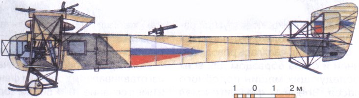
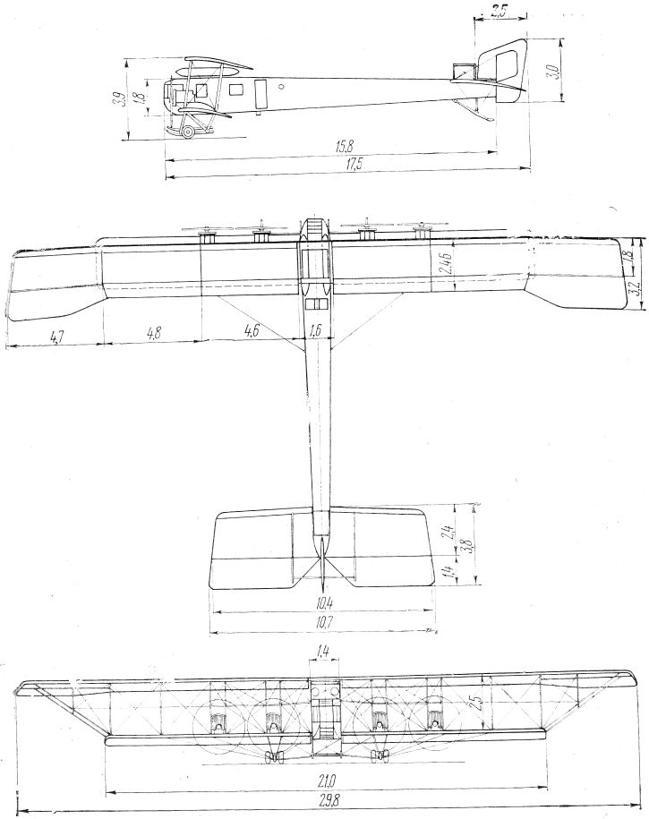
В.Шавров - История конструкций самолетов в СССР до 1938 г.
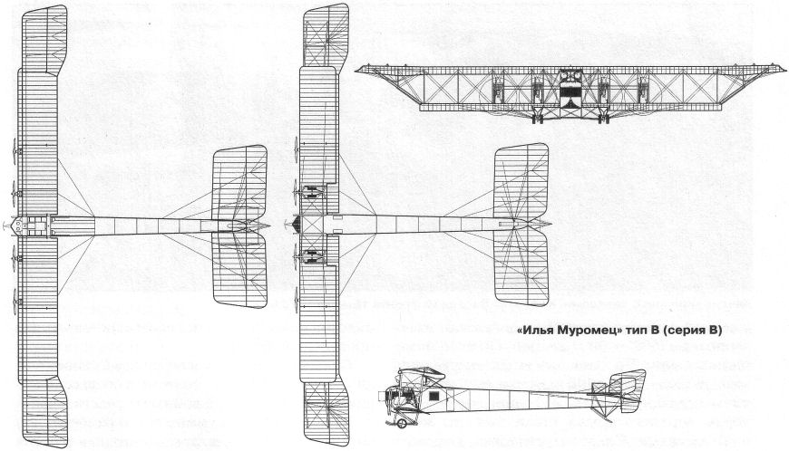
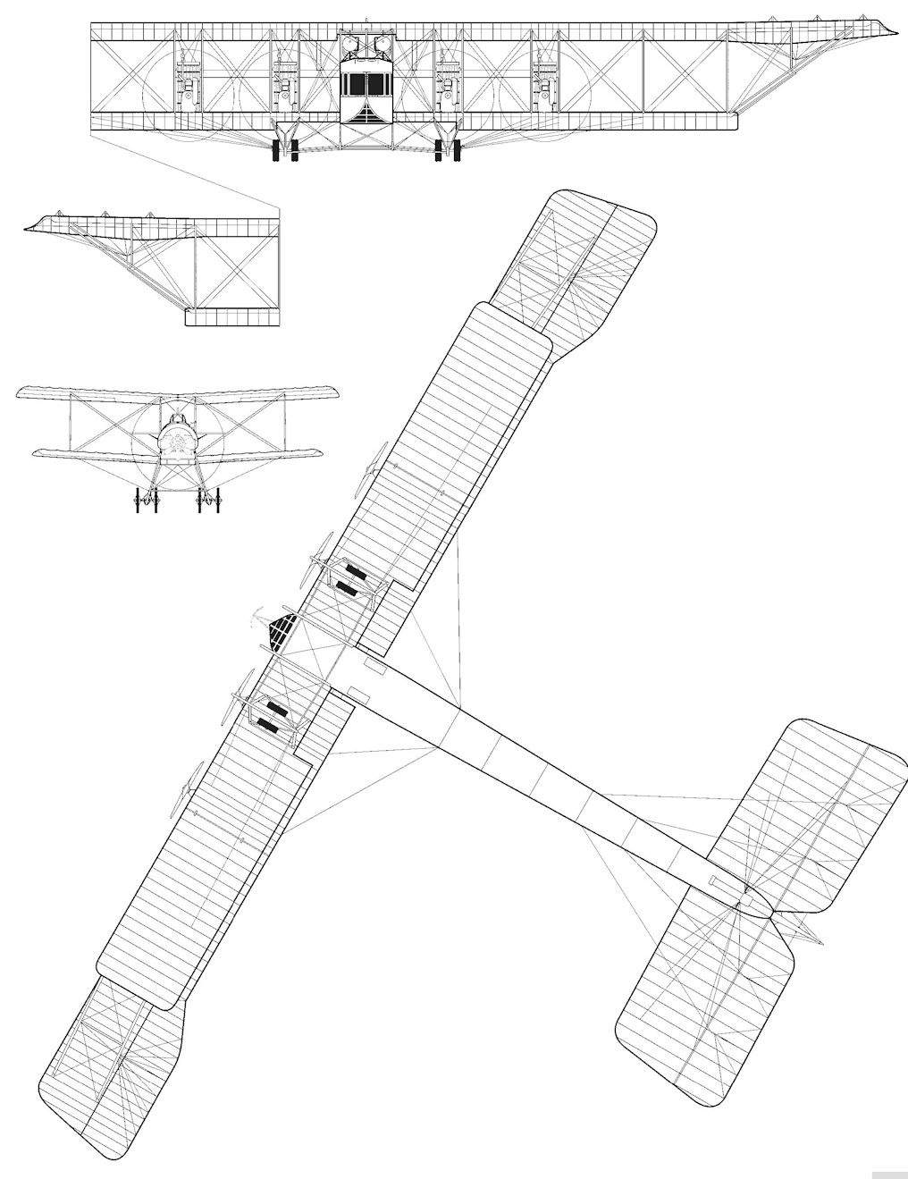
Схема самолета "Илья Муромец" , тип В, 1915 г.
-
-
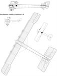
М.Маслов - Русские самолеты Первой Мировой /Эксмо/
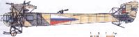
«Илья Муромец» серии В и истребитель С-16
-

-

-

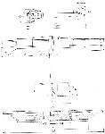
A.Durkota, T.Darcey, V.Kulikov - The Imperial Russian Air Service /Flying Machines/
1. Plywood foot panels. 2. Aluminum sheet. 3. Altimeter (barometric type). 4. Bank indicator (ball in glass tube). 5. Fuel indicator gauge (one each side). 6. Front windscreen (which pivoted on centerline). 7. Tachometer (rev. counter), two each side. 8. Rudder pedal frame. 9. Point at which elevator cables enter semi-circular structure. Full details of subsequent run of cables to 'Deperdussin' type frame not yet ascertained, so this detail is omitted. 10. Engine switches, four mounted on plate, starboard side, position varied. 11. Run of elevator cables from tail through channel pieces. 12. Wooden pilot's seat, wire braced and fixed to floor. No seat belt seen on any photograph. 13. Starboard access panel to wing walks to enable crew member (usually mechanic if carried) to leave fuselage and climb out on to wings to repair or service engines or subdue fires. There was a similar panel on the port side. 14. Fire extinguisher at usual position on starboard side. 15. Upper bomb rack rail (wooden) along starboard side. Second rail below. 16. Rack for Madsen machine gun or rifle. Position varied, it was sometimes situated further aft, on port side. 16A. Compressed air cylinder used for starting Sunbeam engines after forced landing. Enough air carried to start one or possibly two motors only. The position of this cylinder varied, on one machine it was clamped to rear of pilot's seat. It is seen here on port side. 17. Rack, or 'cassette,' carrying 5x2 pud (70lb. or 32 kg.) HE bombs of Granovsky pattern. The rack could be fitted with a support of tubular steel enabling them to be carried free-standing as on port side (see 25). 18. Wheel for aileron control. 19. 'Deperdussin'-type frame for aileron and elevator control. 20. Metal ladder to upper observation position and gun post. 21. Bomb sight (Sikorsky pattern). 22. Stand for machine gun or rifle (port). 23. Hatch cover or bomb bay, also used to take vertical photographs. Hatch cover was presumably lifted out but may have been hinged on one side. 24. Sliding door on port side only on this model. Door was a slim wooden framework covered in plywood and slid between split vertical members and double bracing wires. Handles were fitted on both sides. 25. Bomb rack with support frame to allow free-standing storage. When carrier on side rails was empty it was lifted off and a full rack hooked on to rails. (See side view at CC.) 26. The upper surface here was covered with plywood under fabric to provide support for men adjusting tail bracing or while assembling tailplane. 27. Dotted line shows true shape of aileron tip without wash-out. 28. Plan and side view of cabin area of fuselage. Note upper hatch with wooden plank firestep and position of fuel tanks. Actual position of fuel pipes from tanks into fuselage not known but photographs suggest that they connect with a pump fitted to top cross bracing member, then to engines along the horizontal struts between inner interplane struts. Upper shape of cabin was formed by fabric over light stringers. The lower drawing shows the basic wooden structure of cabin area. Behind the metal framed, aluminum and reinforced glass of the nose area, the cabin was lined with 3mm plywood with a fabric outer skin. The floor was of 10mm plywood and extended only as far as the fuselage former behind the door.
-

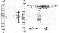
A.Durkota, T.Darcey, V.Kulikov - The Imperial Russian Air Service /Flying Machines/
29. View of starboard lower wing inner section (shown in vertical projection). The left engine is an R-BVZ-6 engine as fitted to Ship II later in its career, with Hazet radiators (note angle). The right engine shows appearance of original 150hp Sunbeam as fitted when Ship II was built. The run of the tachometer cables (actually, Bowden type) is shown over the rear spar. The line near leading edge shows position of compressed air tubes to Sunbeam engines when fitted. 30. Side view of inner R-BVZ-6 engine showing position of oil tank and its supports. Note anti-vibration cables from tanks to interplane struts. Similar cables were fitted to the water expansion tanks over engines. 31. Appearance of Sunbeam motor (outboard) when fitted. The engine mounts were wooden framed and plywood covered. Metal facings were attached under engine bedding lugs. 32. Sketch of cabin showing crew positions in flight. The normal crew for the IM type B (Veh) was four but could vary according to mission. A mechanic could be included as well as a photographer and special observers on occasions. The sketch depicts Ship II while assigned to the 1st Otryad (First Muromets Combat Detachment) based at Kolodziyevka (near Tarnopol) in Galicia, Spring 1916. In May of 1916, the crew were as shown, pilot and Commander, Stabs-Kapitan A. V. Pankrat'yev; at the upper gun position is Podporuchik G. V. Pavlov, who was an assistant pilot; at the bomb sight on the floor is the Deputy Commander, Stabs-Kapitan S. N. Nikolsky acting as artillery officer; operating the bomb carrier is Poruchik K. Smirnov, assistant artillery officer. 33. 25 pud (410kg - 904lb.) HE bomb, one of several developed by a team under Professor N. Ye. Zukhovsky at the Moscow Technical High School in 1915. It was suspended under the center of gravity of the Il'ya Muromets by a strap and cable release inside fuselage. 34. Scrap view of intermeshing strapping of ribs to strengthen structure. A common form of support during early years of airplane construction. 35. Scrap view of undercarriage member reconstructed from a technical description and a study of photographs. The inverted 'V' was a metal tube supported by cables which prevented the skid from bowing upwards during landing pressures. 36. Structure of double wheel. There were two separate rims joined by a circular flange. The outer cover was of leather stitched like a football (soccer ball) case. It is presumed that the wheels with deflated tires then inflated through rim valves and valve flaps. The case was closed with substantial lacing as shown. 37. Roundel and fuselage pennant. 38. Scrap view of standardized metal fitting for fuselage assembly. Note that the side, top and bottom wires were all doubled while the interior transverse wires were single. 39. Scrap view of diagonal fitting with pulleys through which elevator cables passed. 40. Rear view showing position of the two drag wires on both sides. 41. Scrap view of 'Deperdussin'-type frame with wheel control for ailerons. The frame moved fore and aft for elevator control, however, exact method of transmission is not yet known. The strip on the right arm of the frame held finger-push switches to enable the commander to make light signals to his crew. The rudder pedal frame is also shown but the exact run of the cables from the pedal bottoms to the rear is not yet known. 42. Diagrammatic view of bracing wires attached to leading spars. 43. Ditto for rear spars. 44. Key to wiring diagrams: The thin line indicates single wires, the middle dotted line double wires, while the thick line represents triple wiring for load-bearing areas. 45. Scrap view illustrating how multiple wires were assembled, (3-3.5mm piano wire was used). The sketch shows a triple wire example with strips of wood 20mm wide inserted between the wires and the whole bound with tape. This created a streamlined effect as well as ensuring some support if one or even two of the wires were severed. The double wires were of course made the same way. 46. Schematic view of Hazet-type radiators used with R-BVZ engines and occasionally with others. At least one Sunbeam-powered IM had Hazet radiators preferred by the Russians because they offered less head resistance despite their weight and vulnerability to damage from gunfire. The radiators were copied from an early German design which the originators were replacing by mid-1916. Hot water from the engine rose up into the overhead expansion tank, it then drained down into the twin radiators and was drawn off at the bottom rear into pipes which led into the water pump on the engine. The radiators are shown here as parallel but in fact they were always fitted at an angle to the center-line to allow an unimpaired flow of air through the cells. In plan view the radiators were arranged in a shallow arrow form (see 29).
Additional notes:
It should be noted that the IM was supplied with several instruments and items on which information is, at present lacking. In consequence, rather than fictionalize them they have been omitted from the drawings. There was a compass (possibly two) fitted within the pilot's sight and probably on the floor as the compass was also needed by the artillery officer while using the bomb sight. The actual position is not known, neither is the position of the throttles. A throttle for each engine was provided as well as a multiple control (Avtolog) to throttle down all engines simultaneously. The throttles were not operated by the pilot but by the mechanic or the deputy commander on instructions from the pilot.
Other items known to be fitted to Ship II were an arrow indicator operated by the artillery officer which resembled a ship's engine room telegraph in a way, he turned it and the action was repeated on a similar arrow in the pilot's sight. A stand was also provided for the camera. Extra bombs of smaller caliber could be carried in and held with leather straps until required for use. These smaller bombs and missiles could be hand dropped through the bomb hatch or thrown out of the open door. The angular frame fitted on the nose (centrally in the case of Ship II but offset to port on other machines) was a simple artificial horizon devised by Igor Sikorsky. It had small horizontal strips fitted which helped the pilot to judge approach angles while landing, a critical period as far as handling the IM was concerned.
М.Маслов Русские самолеты Первой Мировой (Эксмо)
«Илья Муромец» тип В (серия В)
В конце 1914 г. на РБВЗ строили аппараты «ИМ» серии В, которые отличались уменьшенными размерами и меньшим полетным весом (на 600-700 кг) и, соответственно, более высокими полетными данными. С двигателями «Санбим» и «Аргус» скорость достигала 120 км/ч, «Сальмсоны», в сочетании с радиаторами охлаждения, обладали столь большим воздушным сопротивлением, что даже их значительная мощность не позволяла разгоняться в воздухе более 100 км/ч. Из 14 построенных экземпляров тип В два аппарата оснастили двигателями «Сальмсон» (2x200 л.с), три - «Аргус» (4x150 л.с.), шесть - «Санбим» (4x150 л.с.), два - «Санбим» (2x255 л.с.) и один «ИМ», серийный №167, имел четыре двигателя РБВЗ-6. Визуально эти аппараты также отличались: часть из них имела остекление пилотской кабины с плоским лобовым участком по типу Б, другая часть, называемая «остроносыми», имела клинообразную форму передней части фюзеляжа.
Первый боевой вылет совершил «ИМ» №150 14 февраля 1915 г. В марте в строй вошел «ИМ» №151 - таким образом, до наступления лета 1915 г. в интересах Северо-Западного фронта использовалось два таких воздушных корабля. В начале июля количество боеспособных «Муромцев» увеличилось до пяти единиц. В этот период Эскадра воздушных кораблей перебазировалась в район города Лида, затем в район Пскова. В октябре 1915 г. из состава эскадры выделили боевой отряд в количестве 5-6 машин, которые до конца года базировались под Ригой (станция Зегевольд) и действовали в интересах Северного фронта. Две машины отправили на Юго-Западный фронт с базированием в Колодзиевке.
«ИМ» тип В достаточно активно использовались в 1915 г., одна машина была потеряна в аварии в феврале 1915 г., две другие совершили аварийные посадки после встречи с немецкими истребителями. На начало 1916 г. в составе эскадры числилось 10 экземпляров, которые в течение ближайших месяцев в основном вышли из строя по причине изношенности. Один экземпляр - серийный N“169 - окончательно списали лишь в начале 1917 г. За 1915 г. воздушные корабли эскадры выполнили около 100 боевых полетов, сбросив при этом 1220 пудов бомб.
Летные и технические характеристики «ИМ» тип В
заводской № 150 167
Размах верхнего крыла (м) 28,0 29,8
Размах нижнего крыла (м) 19,2 21,0
Длина (м) 17,1 17,5
Площадь крыльев (м2) 120 125
Вес пустого (кг) 2700 3500
Полетный вес (кг) 3500 5000
Полетная скорость (км/ч ) 100 120
Потолок (м) - 3500
Продолжительность полета (час) - 4,5
Суммарная мощность двигателей: 560 л.с. 600 л.с.
«Аргус» 140 л.с. 4 -
РБВЗ-6 150 л.с. - 4
Описание: