P.Lewis British Aircraft 1809-1914 (Putnam)
Edwards Rhomboidal
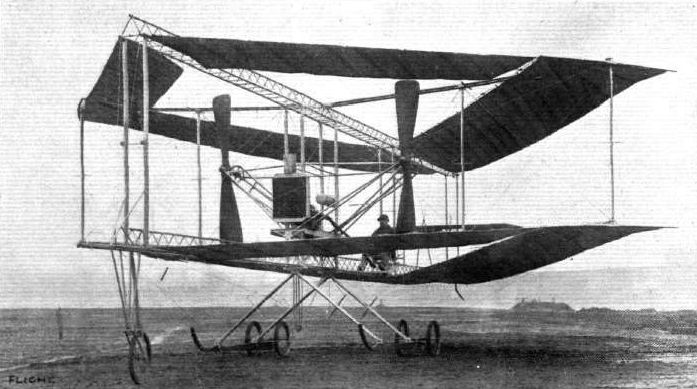
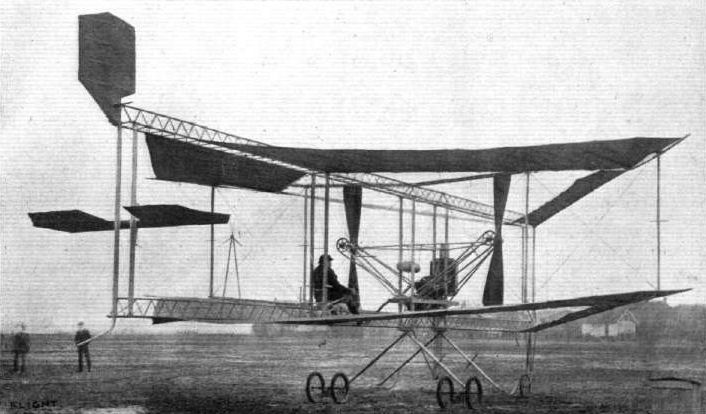
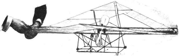
The extremely unorthodox Rhomboidal was tested at Brooklands during 1911. It was an annular biplane in principle, but less refined in execution than the Lee-Richards Biplane. The two main planes, both of which were of the same size and shape, were composed of single fabric surfaces having curved ribs in pockets, similar to the battens of a sailing-yacht, lying parallel to the direction of flight. The "spars" of these surfaces were tension cables stretched between the ends of two central longitudinal compression girders, with pin-jointed struts extended laterally so that the whole of the wings' plan-form was that of a hollow diamond, the rear surfaces having three times the chord of those forward. The trailing-edges also were cables, but these were less strained and permitted a considerable degree of flexibility, with the intention of equalizing the air loads throughout the surface. The upper and lower wings were connected by vertical struts, and the whole machine was rigged with a dihedral angle of about 8°.
The 50 h.p. Humber engine was mounted on the lower main girder in the centre of the hollow of the wings and drove a pair of tractor propellers through chains. The pilot sat farther aft on the same girder and was provided with orthodox single elevator and single rudder controls; as the rudder was mounted above the upper wings and was out of the slipstream it can hardly have been effective. The machine rested on a chassis of two skids, each of which carried a pair of wheels in the Farman fashion, with a single castoring wheel at the front of the lower wings and a spring skid at the back. There is no record of the Rhomboidal having left the ground, and it is possible that it was wrecked and abandoned in favour of the more orthodox Walton and Edwards Colossoplane. Span 38 ft. Length, 48 ft. Wing area. 1.200 sq. ft. Weight empty, 1,600 lb.
Показать полностью
M.Goodall, A.Tagg British Aircraft before the Great War (Schiffer)
Deleted by request of (c)Schiffer Publishing
EDWARDS Rhomboidal biplane. (Walton & Edwards Aeroplane Co., Shed 37, Brooklands)
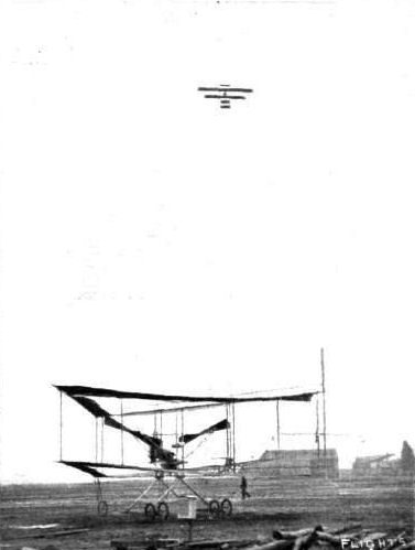
First described in Flight on 5 February 1910 (p.87-90), and reported to be backed by a large automobile firm, believed to be Humber, the Rhomboidal made its first appearance at Brooklands on 11 March 1911. It was not until June that attempts to taxi or to fly were made. On 27 June 1911 the pilot, named Martin Rucker, lost control and ran across a ditch onto the racing track, causing severe damage to the machine. There were no further reports and it was apparently not repaired.
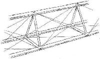
This most unusual form of annular biplane was built around two triangular section longitudinal girders, built up from wooden sections, and was wire braced. The lower girder provided the mounting for the engine and seat for the pilot, and rested on splayed struts, which were the main undercarriage members. These were wire braced and carried twin skids and two pairs of wheels. A nose wheel was mounted at the extreme front and a skid at the rear end.
The wings, in plan, were in the form of a rhomboid or open diamond shape. The structure for these consisted of builtup spars of streamlined section, at top and bottom, and at right angles to the main girders, with interplane struts between. The shape of the wings was maintained by tension cables along the leading edges and curved battens across the chord, but the trailing edges were allowed to remain flexible. Bracing wires from the top and bottom wingtips were taken down to the undercarriage structure. The twin tractor propellers were mounted on shafts on outriggers and were extensively braced by cables to the main structure.
Elevators and a rudder were mounted at the tail, but reliance was placed on wing dihedral for lateral balance.
Power:
50hp Humber four-cylinder inline, water-cooled driving by chains twin tractor 8ft diameter propellers.
60hp Green, four-cylinder inline, water-cooled from June 1911.
Data
Span 38ft
Chord 3ft front areas 9ft rear areas
Area 1,200 sq ft
Length 48ft
Height 14 ft 11 in (16ft 10in to top of rudder)
Weight 1,600lb
Dihedral 8 degrees
Показать полностью
Журнал Flight
Flight, February 5, 1910
AN ORIGINAL ALL-BRITISH AEROPLANE.
PARTICULAR interest attaches to the machine concerning which we are now enabled to give comparatively full general particulars, inasmuch as it is not only novel to a very unusual extent as aeroplanes have heretofore gone, but is of British conception, British design, and British manufacture in its entirety. It is, in fact, one of the numerous machines upon which a great amount of work and thought have been bestowed during the past year or so in this country in a quiet and unobtrusive manner, which cannot fail before long to assure for this country the position that it ought to take in aeronautic matters in the eyes of the civilised world. At the moment we are debarred from giving it a name, inasmuch as those associated with its development prefer to remain in the background until actual success has been achieved, or at any rate until the machine has been brought out to undergo its trials in the full light of day. At the present time it is receiving its finishing touches in readiness for an early test, and consequently the time is ripe when details of a broad character may be made public.
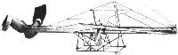
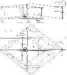
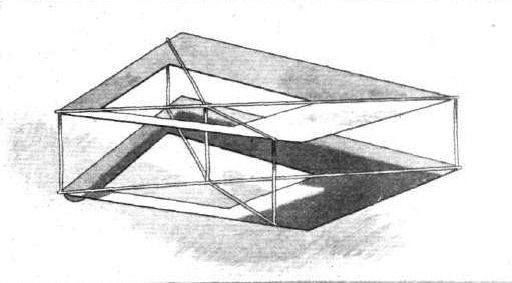
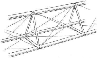
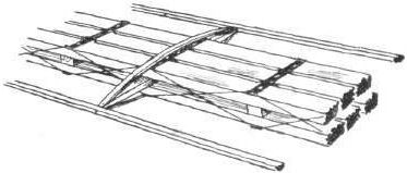
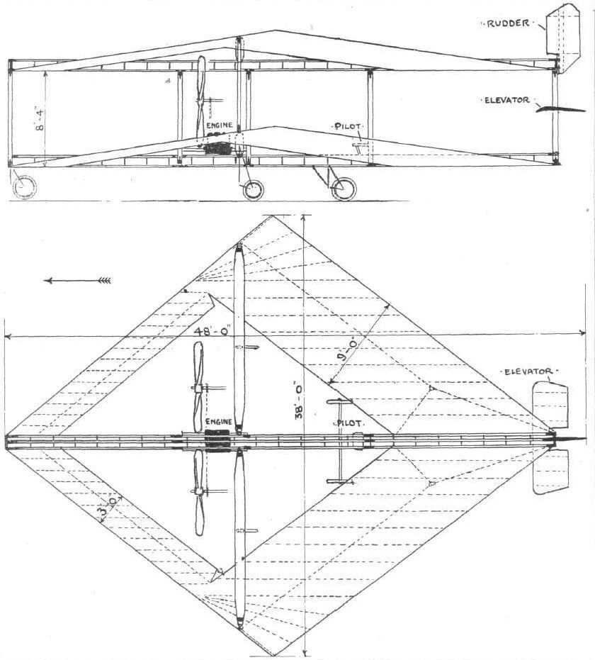
Apart from that we may only add that, as far as the preliminary arrangements of a commercial character are concerned, the enterprise has been backed by a large and very well known firm which is closely connected with the automobile industry. Our illustrations are amply sufficient for the immediate purpose that we have in view. The first of them gives a diagrammatic idea of the principle of construction as applied to a biplane, and is virtually a view of a small paper gliding model that can easily be made by anyone desirous of observing the upshot of that particular form of construction for an aeroplane. Similarly, briefly referring to the other illustrations, the third is reproduced from a photograph of a monoplane model with which numerous experiments were carried out during the initial stages, and with which some very remarkable results - which we ourselves had the pleasure of witnessing - were obtained. And then our large full-page scale drawings include a side elevation and a plan of the big biplane that is now nearing completion, while the two remaining sketches show the details of construction of the two principal members of this big machine.
Essentially the shape of the planes is rhomboidal, with a similarly rhomboidal opening that causes the two front surfaces to be considerably narrower than the two rear surfaces, as may be seen in several of the illustrations. The fore and aft axis lies diagonally across between the two more acute angles of the rhombus, and from either side of this axis the surfaces slope upwards slightly to give the familiar dihedral angle form of construction, the advantages of which most of our readers already know. All that need be added on general principles is that the leading edges of the narrower front, and of the wider back planes are rendered rigid, while all trailing edges are not only made flexible but are given a normal downward trend; for these are the features upon which reliance is placed for giving unusual stability for the machine, and carrying the load centrally in such a way that its weight is equally distributed without any undue concentration of strain at any one place. We do not propose at the moment to go into the question of the why and wherefore for the automatic stability which is apparently obtained, but it will of course be observed that the large central aperture essentially tends that way, and that a compactness is obtained which differentiates the design from any other machines that are at all well known.
Passing direct to the large biplane that is now nearing completion, we may say at once that there are two very marked reasons why considerable interest is demanded by it. Firstly, there is, of course, this new principle on trial, affecting the form of the planes, but also, even apart from that, many of the constructional details that have been introduced are valuable contributions to the constructional development that is now going on all round. The inventor and designer has in this way displayed a degree of constructional skill which is far above the average in a first machine of this kind; and certainly haste to put his ideas to the practical test on a large scale has not been allowed to interfere with the thorough soundness of the job. The new biplane is ambitious in proportions, for it is intended to carry a very considerable weight, representing at least two or three persons, in addition to the comparatively heavy engine that is being installed. An extraordinary degree of strength has been secured with a remarkably low total weight, by the use of wood and of steel wire in a very special way. Thus has a net result been obtained of a total spread of about 1,200 square ft of surface with a total weight of about 1,600 lbs., including 500 lbs. for the 50-h.p. engine.
As a backbone, two main girders are employed, one above the other, 8 ft. 4 ins. apart and some 45 ft. long. Each of them is triangular in shape, built as shown in our separate detailed sketch, some 1 ft. deep and built up of 1 1/4 in. diameter spars with short 1 in. struts and with diagonal wires that run spirally around them and are soldered where they pass over the screw heads that hold the struts to the spars. These long girders are, moreover, made in three separate lengths and are readily jointed together for erection; and the girders when in place are coupled up by five pairs of vertical tie-bars, disposed as shown in our drawing, and of a square cross-section chamfered off fore and aft to reduce their wind resistance.
Universally-jointed on either side of each of these girders is a transverse spar that slopes upwardly outwards and serves to carry the main planes by means of steel cables passing between its extremities and those of the girder to which it is attached. Each pair of transverse spars lies approximately on the level of each of the planes, and these spars are tied together by diagonals that render them comparatively rigid in spite of their ball-and-socket joints. Each spar is built up in the manner shown in our final sketch with six wooden members having a cross-section of 1 3/8 in. by 1/2 in., with intermediate steel wire diagonals soldered to steel straps. Special wire strainers are used during the process of construction of this central portion, and an immensely strong member results. Finally, the completed spar, as illustrated in our sketch, is covered with fabric, and then its cross-section,, which is oval in shape, is approximately 1 ft. in width by 2 3/4 in. maximum depth. As will be observed from the plan, moreover, these spars are about 16 ft. in length.
The planes themselves are of fabric and are carried by steel cables stretched between the ends of the girders and the ends of the spars as already mentioned. The fabric forms a single surface upon bent wood ribs that lie longitudinally through it and are pocketed against it, these ribs tapering off rearwardly and thus giving the desired flexibility to the trailing edge that projects behind the stretched cable. For the front planes, the ribs lie about 1 ft. apart, while at the rear they are situated about 18 ins. apart. The camber of the planes is in the neighbourhood of 4 ins.
Our scale drawings show the position of the engine and of the two 8 ft. wood propellers that lie about 9 ft. 6 ins. apart and almost centrally between the planes. As will be observed, the engine lies just forward of the spars, where it rests on a channel steel frame, and is therefore right in front of the pilot's seat and of the seats which may be provided for passengers. A framing of steel tube is employed for carrying the propellers, which are driven by a pair of chains, one of which is crossed, and are geared in the ratio of about 3 to 1, giving a normal speed of some 600 revs, per min.
Concerning the control, the exact position of the rudder or rudders is not fully determined, provision having been made whereby it can either be fixed at the back as seen in our drawings, or in front immediately behind the fore pair of uprights. It and the elevator form the sole means of control, and both are to be operated by a single universally jointed lever. The idea is to move this lever in one direction for elevating and in the other direction for lateral steering. Finally it will be observed that the machine is provided with five supporting wheels, all of which are spring suspended; and with this we may leave the subject of an unusually interesting machine for the moment, until the next stage in development has been completed. Needless to say, everybody in this country, at any rate, will wish its inventor the success which he deserves, if only because of his originality and obvious inventive ability.
Показать полностью