P.Lewis British Aircraft 1809-1914 (Putnam)
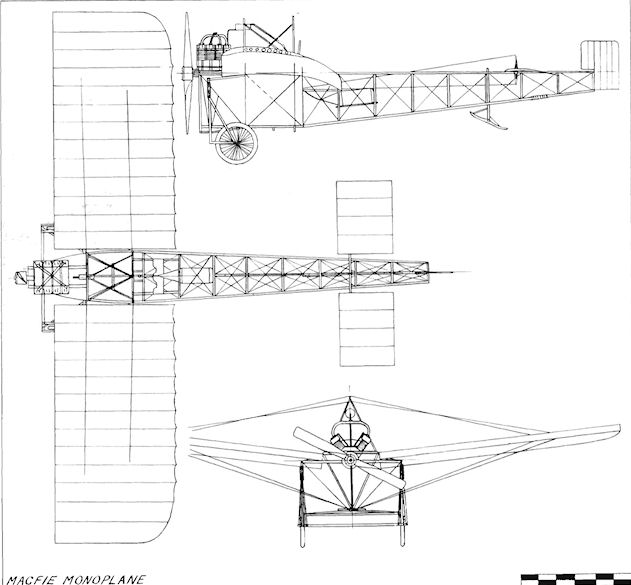
Macfie Monoplane
Robert Francis Macfie was born in San Francisco, California, U.S.A., on 11th November, 1881, and became interested in the problems of flight while in Chicago from 1902 until 1904. Some five years later he came to England and started the construction of his own aeroplane at Fambridge, Essex, on 2nd August, 1909.
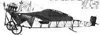
The machine was a single-seat tractor monoplane, of which the fuselage consisted of an open, wire-braced wooden structure of triangular section. An unusual method of building the framework was used. The longerons were connected by cross-pieces, which were butt-jointed to them direct without the use of mortice joints, the system comprising steel angle plates, which were lashed and glued with fine Irish linen tape to keep the members in place. The fuselage was strong and was built quickly.
Parallel-chord wings with curved tips at the rear were mounted on the pair of upper longerons, which also provided the anchorage for the pivot of the elevators in the absence of a fixed tailplane. There was no fixed fin, the rudder forming the extreme rear of the machine. Lateral control was by the popular system of warping. The undercarriage was a simple but sturdy steel tubing unit on the lines of the Bleriot, with a sprung tail-skid supporting the rear of the monoplane. An eight-cylinder air-cooled 35 h.p. J.A.P. engine had been ordered and was delivered on 5th September, a 6 ft. 6 ins. propeller being fitted to use its power.
After six weeks work the machine was completed on 16th, September, having been almost completely hand-built. Trials commenced at Fambridge on the same day and continued for a month until 19th October. Successful flights were achieved after various alterations had been made, following four crashes on the unsuitable field. From 20th October until 10th November, Macfie searched for a better flying ground in Essex and Lincoln, finally selecting Maplin Sands at Shoeburyness, Essex. The monoplane was removed there on 11th November, 1909, and from that date the story of his attempts to fly the machine is one of bad luck and frustration, despite his unfailing determination to succeed with it. Bad weather set in and the aircraft crashed twice; the final blow was dealt by the War Office, who ordered the pioneer off the Sands. During the night of 28th-29th November, the crossing was made from Foulness Island in continuous rain, the machine being deposited in the Kursaal at Southend-on-Sea.
Still undaunted, Macfie set off once again to search for a suitable flying-ground, touring Hampshire, Kent, Surrey, Lincolnshire and the Midlands without success from 1st until 14th December. France appeared to be more receptive to flyers, and he decided to go to Pau, receiving confirmation on 14th December, on which day the machine left Southend for the London Docks, arriving there the following day. Pau was reached on 22nd December, but, on arrival, Macfie was refused permission to fly there.
After a few days rest over Christmas he left for Croix d'Huis, where he stayed from 27th December, 1909, until 3rd January, 1910, but found that the ground was useless for his purpose. On 19th January Macfie returned to London after spending two weeks searching for a suitable flying-field in France, having found either the grounds or the terms imposed for their use unsuitable for his requirements. While awaiting the arrival of the monoplane, he tried once again from 20th until 30th January to find a ground in England, to be told at the end of the month that the machine had been lost in transit in the floods in Paris. It eventually arrived at Blackfriars on 2nd February, 1910, but was by then a complete wreck.
SPECIFICATION
Description: Single-seat tractor monoplane. Wooden structure, fabric covered.
Manufacturer: R. F. Macfie, Fambridge, Essex.
Power Plant: 35 h.p. J.A.P.
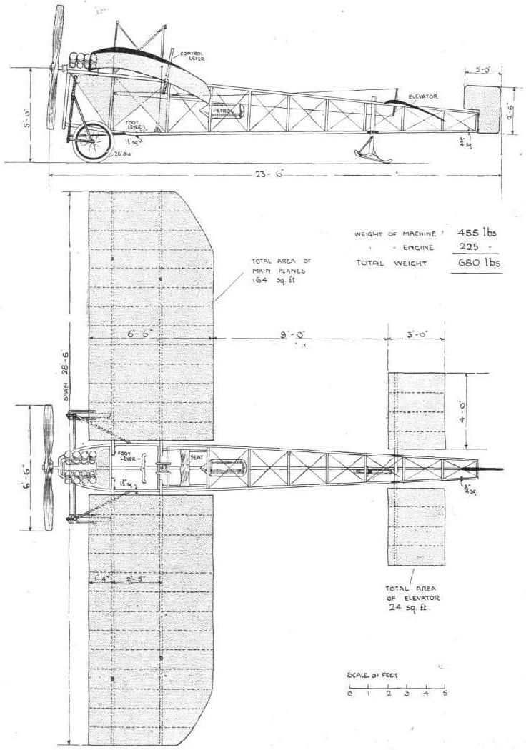
Dimensions: Span, 28 ft. 6 ins. Length, 23 ft. 6 ins. Wing area, 164 sq. ft. Weights: Empty, 680 lb.
Показать полностью
M.Goodall, A.Tagg British Aircraft before the Great War (Schiffer)
Deleted by request of (c)Schiffer Publishing
MACFIE monoplane (Robert Francis Macfie, Fambridge and Maplin Sands, Essex)
Macfie came from San Francisco to England in 1909, and began construction of the monoplane at Fambridge on 2 August 1909. Trials commenced on 16 September 1909 and flight was achieved in the period to 19 October 1909, after various modifications and repair of damage. Fambridge was unsuitable as a flying ground, and on 11 November 1909, the monoplane was taken to Maplin Sands, but was removed by the end of the month after damage, bad weather and a War Office order to move. Unable to find a suitable field in the Southeast and Midlands, Macfie took the aircraft to France, but was refused permission to fly at Pau, and Croix d'Hins was considered unsuitable. When the machine was received back in London on 2 February 1910 it was beyond repair.
The monoplane was a single-seat tractor with a triangular section fuselage consisting of a tapering ash girder, made with butt joints, reinforced with steel fittings, bound by tape, and glued. The whole structure was braced by wires and was mainly uncovered. The castering undercarriage was made of steel tubing and was sprung, as was the tail-skid.
The wing had a marked camber and small dihedral and incorporated a warping trailing edge portion. Two triangulated pylons above the fuselage provided anchorages for bracing wires and the warping control.
Power: 35hp JAP eight-cylinder air-cooled vee driving a 6ft 6in diameter propeller.
Data
Span 28ft 6in
Chord 6ft 6in
Height 5ft to center prop boss
Area 164 sq ft
Area elevators 24 sq ft
Area rudder 4 sq ft
Weight 680 lb
Показать полностью
Журнал Flight
Flight, March 5, 1910
THE MACFIE BRITISH AEROPLANE.
SOME little time ago, as our readers may remember, flight experiments were carried out on the Maplin Sands by Mr. Macfie, who succeeded in making a few long jumps before the military authorities in charge of the gunnery range at Shoeburyness caused these promising trials to be temporarily abandoned. Mr. Macfie transferred his machine to France in the hope of finding a satisfactory trial ground, but meeting with considerable difficulty in arranging for what he considered to be reasonable conditions under which he could continue his experiments, he has once more returned to England, and is now about to conduct further trials over home soil.
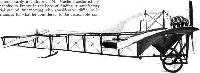
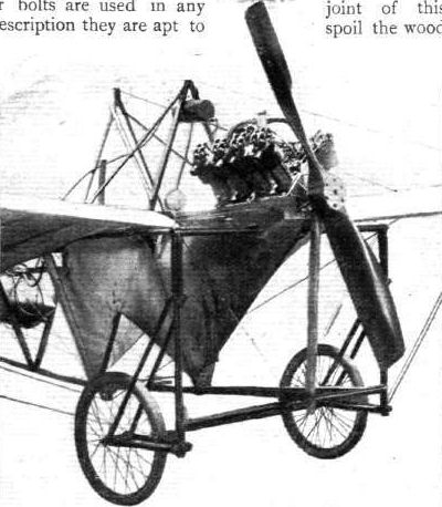
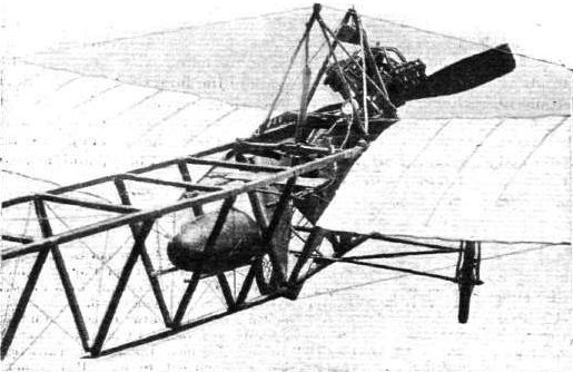
The Macfie aeroplane is interesting as an almost entirely home-made machine, and also because it embodies several ingenious features in the details of its construction. As a type it resembles at first sight the Bleriot monoplane, but the wings have a dihedral angle like the Antoinette. They are fastened to a frame that is built of wood and wire and forms a V-section lattice girder of tapering section. In front, the frame is mounted on a wheeled chassis, and behind it rests upon a skid. The rear part of the frame carries a pivoted tail and a rudder. In front, immediately above the chassis, is the engine, which drives a two-bladed tractor-screw. The pilot's seat is between the wings, and the control, which includes wing-warping, is effected by a single vertical lever and a pedal.
The Frame.
The frame of the machine is a light V-section ash girder measuring about 3 ft. deep at the forward end and 12 ins. deep at the tail. The bottom member lies horizontal when the machine is on the ground, and the two top members, therefore, have a gradual slope from the tail to the forward end of the machine. The front extremity of the frame is formed by a kind of prow that is specially constructed as a support for the engine, pains having been taken to try and reduce the effect of vibration as much as possible.
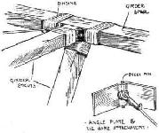
The two upper members of the frame are spaced about 2 ft. 6 ins. apart at the widest point, which is immediately between the wings, and they likewise taper together towards the tail, where they terminate 12 ins. apart. At intervals the longitudinal members are stayed by cross-pieces, and the fastening of these is one of those peculiarities, it might almost be said curiosities, in the constructional detail of the Macfie aeroplane. An accompanying sketch shows exactly how the joints are made.
The girder struts abut flat and true against the bearer spars, but they do not make any sort of a mortice joint. Their fastening is effected by the use of steel angle-plates that are lashed to the different members by strips of fine Irish linen tape. The tape is previously soaked in a solution of glue and water and is bound in place while wet so that the binding contracts tight and hardens while drying. This very original method of bracing a frame Mr. Macfie claims to have found extremely satisfactory, especially for an experimental machine. He also found it to be a very expeditious method of building up a frame, and ascertained as the result of much hard usage that the joints would withstand strains very well indeed. Moreover, if one should loosen it is a simple matter to remake it, for the component parts, with the exception of the binding, are intact. When screws or bolts are used in any joint of this description they are apt to spoil the wood so much if they work loose that it is difficult to remake the joint in exactly the same place. This is, of course, one of the principal claims that Mr. Macfie makes for his system of construction.
An incidental feature associated with this method of jointing is the anchorage that it provides for the diagonal tie-wires used to complete the trussing of the frame. Close inspection of the accompanying sketch already referred to will show that the steel angle-plate is indented at the corner, so as to receive a steel pin. The angle-plate is also drilled so that the centre of the pin, which is cranked, can project through to the front, where it forms an eye for the anchorage of the tie-wire.
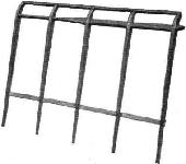
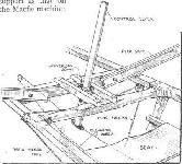
The same system of binding, it may be remarked, is also employed for joining together the two lengths that compose each of the longitudinal spars of the main frame. In front the frame is supported on a wheeled chassis constructed of steel tubing. The details of this chassis are sufficiently clearly shown by one of the accompanying photographs to need no special description.
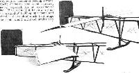
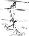
It will be observed that, in the main, it consists of a rectangular frame, to the upright members of which the two wheels are attached by swivel brackets. There are two forked brackets to each wheel, and one of them abuts against a helical compression spring situated near the top of the vertical member in the chassis frame. These springs form the suspension members of the machine, and enable the wheels to rise and fall vertically without interfering in any way with the swivelling movement. She hubs of the wheels are connected by a light axle that is hinged at each end. At the rear the frame is supported on a light shoe or skid shown in the sketch above.
(To be concluded.)
Flight, March 12, 1910
THE MACFIE BRITISH AEROPLANE.
(Concluded from page 154.)
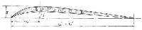
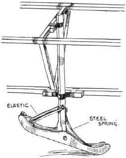
THE skid was specially designed for use on the sand over which the first experimental trials were carried out. It is very light and is provided with a combination of elastic and steel springs, as shown in one of the accompanying sketches. The shoe itself is pivoted to a vertical wood column that is free to rotate in its supporting brackets.
The Wings, Elevator and Rudder.
The wings of the Macfie monoplane have a span of 28 ft. 6 ins., and a chord of 6 ft. 6 ins., which gives an aspect ratio of 4.4. They are set at a dihedral angle and are double surfaced. A feature in connection with their plan form is the removal of their trailing corners for a distance of about 3 ft. from the extremities along the trailing edge.
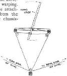
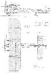
The surface material, for which Continental fabric No. 100 B has been used, is laid on a skeleton framework consisting of two main spars and a set of shaped ribs in each wing. The main spars are of I-section, those in front being rigidly bolted to the frame of the machine, while those behind are each so fastened by a single bolt that they possess a certain amount of hinge action, which is employed for purposes of warping. The details of the attachment of the rear spars to the main frame of the machine is shown in one of the accompanying sketches.
The ribs are spaced along the spars at intervals of about twelve inches, and each rib consists of a built-up member representing the camber of the wing section. The details of this construction are also shown in an accompanying sketch, where the principal dimensions of the rib are given and also the method by which it has been made as light as possible. Further light is also thrown on these details of construction by an accompanying photograph, which shows a portion of the skeleton framework of the elevator tail. There are some differences between the actual details of this member and of the main frame, but the same system is followed in both cases. The ribs, it will be noticed, project beyond the front spar, and their extremities mortice into a kind of U-section member that forms a rigid leading edge along the front of each wing. The ribs also overlap the rear spar, and in this case form a flexible trailing edge. In the construction of the tail there is no rear spar, properly speaking, but it will be observed from the photograph aforementioned that the ribs are tied together near their extremities by a light lath. Attention should also, perhaps, be drawn to the shape of the main spar in the photograph of the tail framework, as this member has a different section to that employed for the main wings. For its span, a much more massive spar is employed in the tail, owing to the fact that it is so mounted as to be capable of rocking in its supporting brackets, the tail being used as an elevator as is the case on most monoplanes.
In applying the surface fabric, a system is adopted of stretching the material on a kind of former in advance. The former is so constructed that it is possible to transfer the stretched fabric direct to the machine without releasing the tension. This method was, we understand, found to be not only very satisfactory in its result, but also a great time-saver, the surfacing of an aeroplane being commonly one of the longest jobs in its construction compared with the apparent amount of work that it involves.
After the surface material has been applied, the wings are braced by the attachment of tie-wires and bars. Flat strip steel is used for bracing the forward main spars to the chassis-frame, but elsewhere steel wire is employed, mainly on account of the movement necessitated by warping. In connection with the attachment of the tie-bars from the forward spars to the chassis frame, it should be pointed out that these slope backwards as well as upwards from their anchorage, in order, according to the designer, to give the spars additional rigidity in overcoming head resistance.
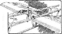
In addition to the tie-wires beneath the wings, there are others above, which pass, between corresponding points in the main spars, over a central triangular framework that projects as a strut above the centre of the machine. In the case of the tie-wire between the rear main spars a pulley wheel is provided for its support on the strut, owing to the movement that takes place when the wings are warped. Details of this attachment are illustrated in one of the accompanying photographs, which shows the position of the pilot's seat.
The rudder is an interesting example of the use of Venesta wood. It consists of two panels, fastened to a light skeleton frame, and each panel consists of three layers of wood, of which the individual thickness is only one twenty-fifth of an inch. This form of construction produces a smooth rigid surface that is not easily damaged and is reasonably light. It seems particularly suited to a rudder that is as much over-hung in its support as that on the Macfie machine.
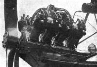
The Engine.
The engine installed on the Macfie aeroplane is a 35-h.p. 8-cyl. Jap. The cylinders are arranged V-fashion and are air-cooled. The engine is situated right up in the bows of the frame and is carried on two timber bearers that are rigidly attached to an extension of the main-frame of the machine. The tractor-screw, which is a two-bladed design constructed in solid teak, is mounted direct on the end of the crank-shaft. It has a diameter of 6 ft. 6 ins. and a pitch that is calculated to produce a flight speed of 40 miles an hour at 1,200 r.p.m., after allowing for a 30 per cent. slip. Close inspection of some of the accompanying photographs illustrates an obvious cutting-away of the trailing edge of the propeller, a modification from its original form that was found to result in a considerable improvement in the tractive effort.
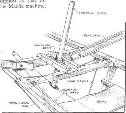
The Control.
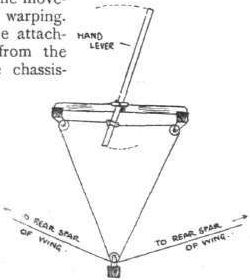
The control of the Macfie aeroplane is accomplished by means of a universally pivoted lever, and also by the aid of a pivoted foot-rest that serves the purpose of a pedal. The pedal controls the action of the rudder; and is independent of all other connections. The lever Is mounted vertically and directly in front of the pilot; its position and method of attachment is very clearly illustrated by the accompanying sketch and also by the various photographs. It can be moved in any direction and with either or both hands as the operator may find most convenient. Its lower extremity carries the wires that operate the elevator-tail and near the lower end of the lever are attached the wires that produce the wing warping. The connections of these latter wires and the manner in which they are "reversed" by the aid of pulleys attached to the main frame, forms the subject of a separate diagrammatic sketch.
This use of a single universally pivoted lever for the double purpose of warping the wings and working the elevator - in a manner that corresponds to the Bleriot control - must not be confused with the Wright system, wherein a similar lever is employed for the dual purpose of warping and steering. The arrangement on the Macfie machine is not associated with any particular system of control, it is merely a device for reducing the number of levers that would otherwise be necessary.
On the Macfie machine warping and the manipulation of the elevator can be carried out by the use of a single lever, but this does not imply that there is necessarily any purpose in the interconnection other than that associated with the pilot's convenience.
Moving the lever to and fro operates the elevator, moving it from side to side warps the wings. Warping or the manipulation of the elevator can be accomplished independently with the lever in any position; that is to say, supposing the pilot happens to be holding the lever forward of the neutral position for the purpose of setting the elevator, he can instantly warp the wings by a sideways movement without in any way upsetting the elevator adjustment, and vice versa. The manipulation of the rudder, which is commonly necessary in connection with any wing warping operation, is independently accomplished by the use of a pivoted foot-rest to which the rudder is directly connected.
Показать полностью