A.Jackson De Havilland Aircraft since 1909 (Putnam)
De Havilland Biplane No. 1
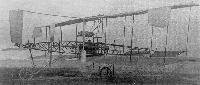
This was a single seat biplane of cotton covered, white wood construction with a fixed tailplane, front elevator, uncompensated ailerons, a large rudder above the tailplane but no fixed fin. It was braced with piano wire and mounted on an undercarriage of bicycle tubing with four bicycle wheels. The pilot sat in a wicker chair with a lever on the left which controlled the elevator, one on the right which moved the rudder, and a footbar connected to the ailerons.
The four cylinder, horizontally opposed, water-cooled engine, designed by Geoffrey de Havilland and made by the Iris Motor Company at Willesden, developed 45 h.p. at 1,500 r.p.m. It weighed 2 cwt. and was mounted at right angles to the direction of flight in order to drive two pusher propellers with adjustable aluminium blades through steel shafting and bevel gears.
There were no working drawings but the aircraft was completed from rough sketches early in 1909 in a rented workshop off Bothwell Street, Fulham, London, with the assistance of F. T. Hearle and of Mrs. De Havilland who sewed on the cotton covering. In May 1909 it was taken on a Commer lorry to Seven Barrows near Newbury, Berks, but over six months elapsed before undercarriage, propeller drive, engine and control adjustments were finished so that fast taxying could be attempted whenever the wind was calm.
It flew for the first and only time in December 1909 after a downhill takeoff into wind. Without pilot training and deprived of instinctive control by his complex system of levers, de Havilland overcorrected when he felt himself airborne and pulled the nose up so steeply that the wing spars failed and the aircraft broke up when it crashed from a height of 15 ft. The designer was uninjured and the engine was salvaged.
SPECIFICATION AND DATA
Construction: By G. de Havilland and F. T. Hearle at Bothwell Street, Fulham, London, S.W.6
Power Plant: One 45 h.p. de Havilland / Iris
Dimensions:
Span 36 ft. 0 in. Length 29 ft. 0 in.
Wing area 408 sq. ft.
Weights: All-up weight 850 lb.
Показать полностью
M.Goodall, A.Tagg British Aircraft before the Great War (Schiffer)
Deleted by request of (c)Schiffer Publishing
De HAVILLAND biplane No.l (Geoffrey de Havilland, Bothwell Rd., Fulham & Newbury)
The design and manufacture of this machine began in 1908 and continued throughout 1909 at Fulham until November, when it was moved to a shed at Seven Barrows near Newbury on Lord Carnarvon's estate for final assembly. This was completed and initial tests were carried out by December, when, during a fast run, de Havilland attempted to take off. This resulted in complete failure of the wing spars, made from weak pinewood. de Havilland was assisted with the construction by FT. Hearle, later a director of the DH company, and his wife.
The design was a three bay biplane with twin pusher propellers. The fuselage was an open girder tapering to the front, which mounted a divided elevator, and to the rear where the rudder was pivoted between the girder and a boom mounted on the top wing. Single acting ailerons on the top wing provided lateral control. The undercarriage had front and rear wheels in addition to the main pair, supplemented by wingtip skids.
The engine was also designed by Geoffrey de Havilland and was made for him for ?250 by the Iris Motor Co. of Willesden, where his elder brother Ivor had been chief designer before his early death.
Power: 45hp Iris four-cylinder horizontally opposed water-cooled driving two aluminum adjustable pitch propellers through shafts and gearing.
Data
Span 36ft
Chord 6ft
Gap 6ft
Area 408 sq ft
Area elevators 36 sq ft
Tailplane 25 sq ft
Rudder 7 sq ft
Length 29ft
Height 10ft
Weight 850 lb
Показать полностью
P.Lewis British Aircraft 1809-1914 (Putnam)
De Havilland No. 1
In 1908, Geoffrey de Havilland started to build his first aeroplane, and was assisted in both the design and construction by his friend F. T. Hearle. The machine was completed in a shed at Fulham during early 1910, and was powered by a four-cylinder, horizontally-opposed engine which developed 45 h.p. Owing to the lack of suitable aero engines of light weight, de Havilland designed his own power-plant and engaged the Iris Motor Company of Willesden to construct it. Water-cooling was employed, the radiator being mounted in the centre-section of the upper wings.
The lay-out adopted was that of a pusher biplane, with an adjustable tailplane and movable rudder at the rear and elevators at the front. The non-staggered three-bay wings, with a 6 ft. gap, were fitted with inverse-tapered ailerons on the upper tips. The fuselage consisted of an uncovered, wooden-girder structure, braced with wire, in which was mounted the engine behind the pilot's seat. Two aluminium propellers of adjustable pitch were mounted between the wings, and transmission to them was effected through shafts and bevel gearing.
Upon completion, the de Havilland No. 1 was taken to Crux Easton, Hants., for testing. The first test flight was made early in April, 1910, with Geoffrey de Havilland as pilot. The machine left the ground, but after flying for about 35 yds. the port wings collapsed and the aircraft crashed, fortunately without harm to its pilot.
SPECIFICATION
Description: Single-seat canard pusher biplane. Wooden structure, fabric covered.
Manufacturers: G. de Havilland and F. T. Hearle, Fulham, London, S.W.
Power Plant: 45 h.p. Iris.
Dimensions: Span, 36 ft. Length, 29 ft. Wing area, 408 sq. ft.
Weights: Empty, 850 lb.
Показать полностью
Журнал Flight
Flight, April 9, 1910
ANOTHER ALL-BRITISH BIPLANE.
DETAILS OF THE DE HAVILLAND MACHINE.
UNFORTUNATELY, the actual machine with which we are concerned in the present article was one that proved to have a very short life, although it is none the less interesting on that account, for two distinct reasons. On the one hand, it is now being replaced by a second machine designed and constructed in the light of the knowledge gained from it; and in the second place, there is much to be learned from the mere fact that this initial attempt at aeroplane building resulted somewhat disastrously. Fortunately for the British industry, Mr. G. de Havilland, its designer and builder, is a man of the type whose enthusiasm and determination is apt to increase rather than diminish after any preliminary setback; while equally fortunate is it for readers of FLIGHT that he should be willing to place much of the experience that he has just gained at the disposal of fellow British workers in the interests of the aeronautic movement.
The machine of which we are, by his courtesy, now enabled to give a fully illustrated description, was built entirely by himself and by his assistant, Mr. F. T. Hearle. And they it is who are now alone busily engaged with an exceedingly promising "Havilland No. II," although possibly, for the sake of accelerating matters, Mr. de Havilland would feel disposed to consider the advisability of arranging for some other would-be pioneer to join him if the right man were to come forward to help him bear the burden of the undertaking. Needless to say, the expense of building preliminary machines like these is considerable if the task is shouldered, as it has been in Mr. de Havilland's case up till now, by one man only.
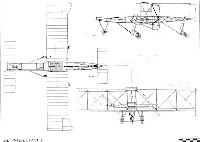
Briefly stated the machine in question was a 36-ft. span biplane, having a front mono-elevator, an adjustable mono-tail, a rear vertical rudder, and hinged wing-tips mounted near the extremities of the upper main planes. It was supported on three wheels - one beneath the tail - and was provided with an additional front wheel beneath the elevator, as well as with skids below the ends of the lower main planes. Also it should be mentioned in advance that it was propelled by a pair of bevel-driven screws situated behind and between the main planes on either side of the central girder.
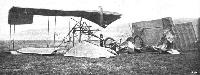
And then it should be added that the past tense has advisably been used in the foregoing paragraph, inasmuch as the first free flight of the machine terminated in almost complete wreckage. The first time that it left the ground it did so after travelling some 40 yards on a downward slope under its own power; it then rose at rather a steep angle, which was corrected by the pilot; and almost immediately afterwards - about 35 yards from the take-off - the left main plane doubled up, causing the machine to fall heavily forward and to the left. Luckily, Mr. de Havilland himself was not hurt, but it will be observed from some of the photographs which we reproduce that the machine as such, apart from the propelling mechanism, the rudder, and the tail, was, for all practical purposes, virtually annihilated by the fall.
As will be observed from what now follows, some important and original features are embodied in this machine, although in general principles there is no radical departure from systems that have proved successful in other cases hitherto. Also, the student of details would do well to bear in mind that this particular machine showed itself to be insufficiently strong for its purpose, thereby, by the way, indicating not only the inadequacy of the cross sections employed, but also the great difficulty that there is in selecting suitable woods for aeroplane construction. To a large extent a form of American whitewood was chosen by Mr. de Havilland, chiefly in order to obtain a good straight grain, but the subsequent fractures indicate an internal softness which was not apparent previously, and we understand that the very much stronger machine now in hand will have silver spruce, ash and hickory in place of the whitewood.
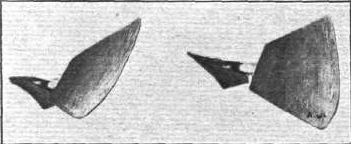
Referring to the special features of Mr. de Havilland's design, it should briefly be mentioned here that these include a neat form of bevel drive for the two propellers in conjunction with the 4-cylinder horizontal opposed engine that also owes its origin to this same designer; while even the propellers themselves are unlike those on other flyers, inasmuch as the aluminium blades are adjustable as to pitch, and as to twist.
Our Illustrations.
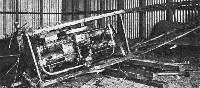
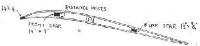
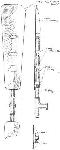
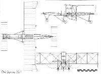
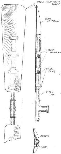
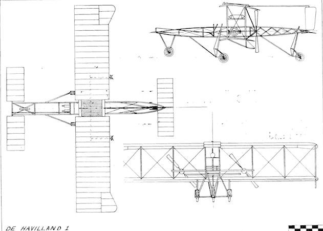
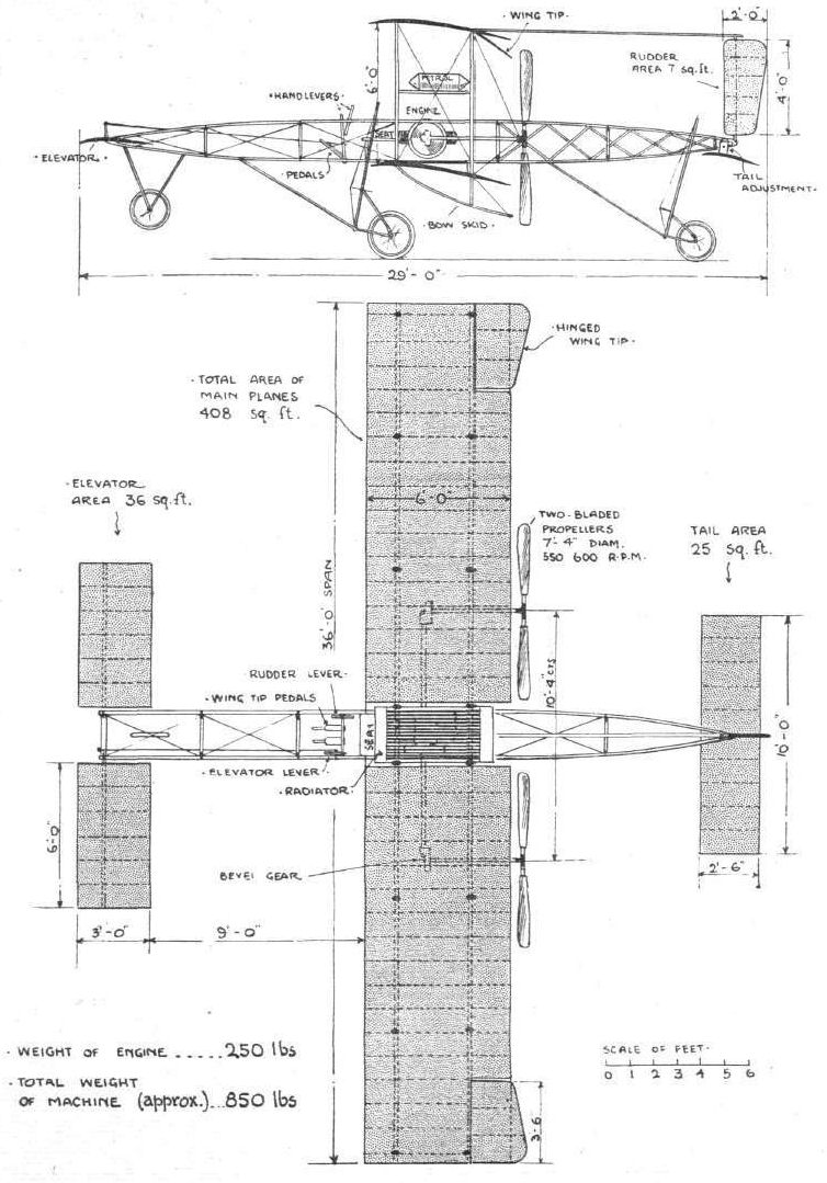
Concerning the photographs that we reproduce herewith, it will be observed that one of these only shows the "Havilland No. I" complete and prior to the accident, while two others were taken from the wreck. The first of these is sufficiently clear to be self-explanatory in very large measure, while the other two repay inspection for the light that they throw upon the whole matter. The remaining photograph includes two views of the propeller, and demonstrates the manner and extent to which the blades are adjustable; while among the line drawings will be found detailed sketches showing the construction of the main girder, of the principal planes, and of the propeller, in addition to the full page that contains scale drawings of the kind that we have made peculiarly our own. Wherever possible, dimensions have been added to these line drawings, and hence it is unnecessary to repeat this extremely valuable information in the text.
(To be concluded)
Flight, April 16, 1910
ANOTHER ALL-BRITISH BIPLANE.
DETAILS OF THE DE HAVILLAND MACHINE.
(Concluded from page 268.)
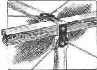
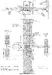
The Central Girder.
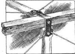
RUNNING from end to end, and causing the entire propelling mechanism to form a single unit with the elevator in front and with the tail and rudder behind, the large girder is built up of wood with metal clips and steel wires as indicated in our illustrations. The longitudinal members have a cross-section of 1 1/2 in. by 1 1/2 in. at the thickest part, and each is made in two parts, lap jointed at the centre, while beneath these members in the immediate neighbourhood of the engine are fitted angle-steel stiffening members, each of which is about 3 ft. 6 ins. long. At the widest place this girder is 2 ft. 4 in. wide by 2 ft. deep, while the lattice members at the rear (which are added subsequently to original intentions) are 1 1/4 in. wide by 1/4 in. in depth. For carrying the propellers with their bevel gear, tubular members are employed branching out on either side of the main girder, and here it may be observed that the engine lies snugly with its comparatively short crank-shaft at right angles to the direction of travel, while continuation shafts are carried from both its ends to the bevel gear-boxes into which the longitudinal propeller-shafts also pass. A very compact substitute is thus obtained for the more usual chain drive, and an engine of the de Havilland type is thus caused to stow very snugly away.
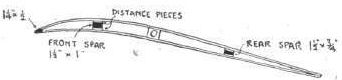
The Main Planes.
These are built up in four parts, each pair of which is bolted together by means of flitch-plates and is then secured by bolts to the engine frame. Wooden spars are employed of the dimensions given in our separate sketch, and it will be observed that distance pieces are fitted between the ribs and the spars in order to give the latter a greater depth where the ribs are attached, and thus to prevent the fabric from sagging down between the ribs and assuming an ugly shape by resting on the spars. The arrangement of the thin webs between the two surfaces will also be noted, and, of course, it will be understood that a double fabric surface is obtained. Incidentally, we are told that a good deal of trouble was experienced with this particular fabric, owing to its tendency to contract in damp weather, even to the extent of distorting the planes, and to hang in festoons when the atmosphere was dry.
Eight pairs of vertical struts are arranged between the upper and the lower main planes, the distance between these planes being 6 feet, as may be observed from the drawing.
Also it may be added that the leading edge of the lower plane stands about 4 feet from the ground under normal conditions. As regards the wing tips on the upper planes, the plane which we give shows precisely the manner in which these are hinged, so as to be operated from the pedals that are situated in front of the pilot's seat.
Elevator, Rudder, and Tail.
Each of these three members - the elevator, the rudder, and the tail - is formed with spars of steel tubing. The area and shape of each is clearly marked on the drawings, and it will be observed, moreover, that provision is made whereby the angle of the tail can be altered if necessary. For controlling the machine the elevator is coupled up to a hand lever on the left, while the rudder can be actuated from a lever on the right.
The Chassis.
Normally when the machine is resting upon the ground or is running along, it rests upon the three spring-suspended wheels that are anchored to the main frame by guide-rods and by forwardly mounted radius-rods. The two front wheels are, of course, arranged together in a kind of tubular frame of their own, and it is they that take the bulk of the weight initially. The details of this chassis are likely to be altered very considerably indeed in Mr. de Havilland's next machine, for he found the present scheme of arranging clumsy and otherwise unsatisfactory. We have already mentioned the additional front wheel and the supplementary side skids that are used.
The Propelling Mechanism.
Details of the engine will be found in a separate article, for which we hope to find room in FLIGHT very shortly; but it must suffice here to say that it weighs about 250 lbs., and that its four 4 1/2 in. bore by 4 3/4 in. stroke cylinders develop about 45-h.p. at 1,500 revs, per min. We are told that it ran with an entirely satisfactory absence of vibration on t he "Havilland No. I" and in fact that it, with the whole propeller drive, fully came up to all expectations. In the machine a radiator built up of 3/4 in. tubes was fixed at an angle of 1 in 6 between and beneath the two parts of the upper main plane, and natural circulation took place through large aluminium pipes coupling it up with the jackets.
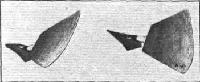
Concerning the propellers, our illustrations show very clearly how four clips are used for securing each of the sheet aluminium blades to the single steel tube which passes unbroken right through the T - shaped hub, and it will readily be understood how these clips permit the angle of the blade with the tube to be adjusted at each of those four points, and thus permits the twist as well as the pitch to be varied. Centrifugal force is guarded against by the thrust washers, and the whole of the back of the blade is neatly covered in with a stiff millboard casing in order to provide a smooth rear surface.
One advantage of this form of propeller construction is that a considerable amount of strength is ensured at the root of each blade where it passes into the hub. This is so not only because the steel tube is continuous from end to end, but also because its central portion is wood filled. On "Havilland No.I" the two-bladed propellers have a diameter of 7 ft. 4 in., and each propeller weighs about 14 lbs.
Показать полностью