P.Lewis British Aircraft 1809-1914 (Putnam)
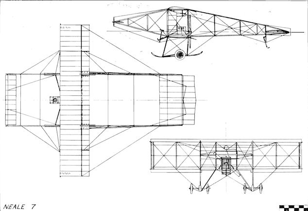
Neale 7 Biplane
Following his monoplanes of 1909, John V. Neale produced in 1910 a single-seat pusher biplane with a patented special system of lateral control. At that time Wilbur and Orville Wright were taking legal action against infringements of their system of patented wing warping, and the Neale Biplane was designed with particular attention to its lateral controls to avoid any trouble arising from litigation.
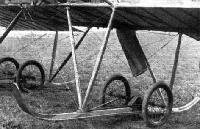
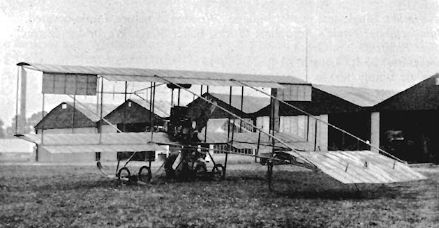
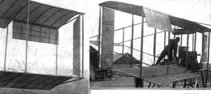
Apart from its controls, the machine was a straightforward design of the popular and successful - if rather uncomfortable - boxkite type. A four-cylinder 35 h.p. Green engine supplied its power to a two-bladed propeller of very generous area. Elevators were provided in front of and behind the main planes, but the usual type of centrally-disposed vertical rudder was replaced by one at each wing-tip, hinged to an additional interplane strut set just inside that on the front at the tip. Ailerons also were incorporated on the upper wings. The machine's undercarriage consisted of the normal combination of two pairs of wheels with their attendant skids.
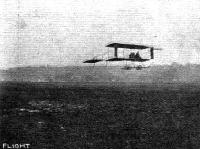
The first flight of the Neale 7 was made on 1st August, 1910, testing being carried out by Neale and Bertie Rippin. During the trials at Brooklands the unusual wing-tip rudders were found to be so effective that the ailerons were discarded. It was claimed that a deflection of 5° of the rudders was sufficient to turn the aircraft in its own length, the theory behind the new system being that a conventional rear-mounted rudder tended to force the nose into wind, while side rudders could undertake the functions of both steering and lateral control.
SPECIFICATION
Description: Single-seat pusher biplane. Wooden structure, fabric covered.
Manufacturers: Neale's Aeroplane Works, Baker Street, Weybridge, Surrey.
Power Plant: 35 h.p. Green.
Dimensions: 33 ft. Length, 41 ft.
Weights: Empty, 800 lb.
Performance: Maximum speed, 41 m.p.h.
Показать полностью
M.Goodall, A.Tagg British Aircraft before the Great War (Schiffer)
Deleted by request of (c)Schiffer Publishing
NEALE VII biplane (J.V. Neale, Neale's Aeroplane Works, Baker St., Weybridge)
Neale had by now acquired a works in Weybridge, but continued to fly at Brooklands He brought out the biplane from his shed on 8 August 1910, taxied it for the first time and flew it soon after. Its origin and ownership became the subject of some controversy, with a pupil pilot named Rippin, who damaged it at the end of September, after which only Neale seems to have handled the machine until flying ceased in November.
The machine was designed with a control system to avoid problems over the Wright patent for lateral control. Although different from the methods of control in general use, its originality was contested from as far afield as America and Australia in letters to the press.
This was Neale's last design, although in November, he was proposing the construction of a large dirigible, for which he was seeking funds. It is believed that the Neale biplane was dismantled and the parts used in a machine by another hopeful constructor.
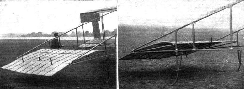
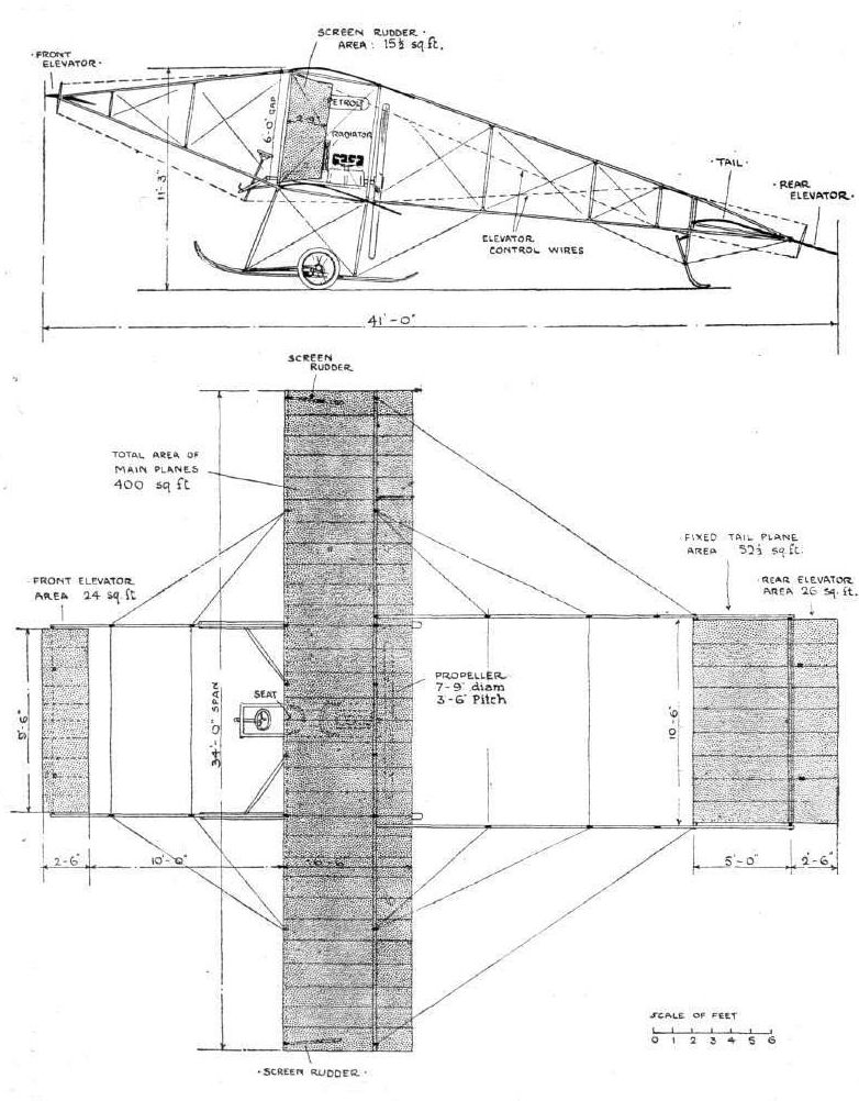
The layout was of a conventional, equal span pusher biplane of the period, with front and rear elevators carried on booms, which were parallel in plan. A special feature was the omission of a rudder at the tail, this being replaced by rudders at each wing tip. These were of single acting type and were hinged on posts just behind the front outer interplane struts, where they not only provided directional control, but caused a 'screened area' over the top wing tip and aileron. Lift was thereby lost on one side, sufficient to make the ailerons redundant, and these were disconnected.
Power: 35hp Green four-cylinder inline water-cooled driving a 7ft 9in diameter propeller
Data
Span 34ft
Chord 6ft 6in
Gap 6ft
Area 400 sq. ft
Area tailplane 52 1/2 sq. ft
Area rear elevator 26 sq. ft
Area front elevator 24 sq. ft
Area screen rudder 15 1/2 sq. ft each
Length 41ft
Weight 800 lb.
Max speed 41mph
Показать полностью
Журнал Flight
Flight, October 8, 1910
THE NEALE BIPLANE.
A NEW PRINCIPLE OF CONTROL DESIGNED TO AVOID THE WRIGHTS' PATENTS.
THOSE who have paid the merest superficial attention to the principles of modern aeroplane control are aware that lateral stability is maintained either by twisting the wings or by using independent horizontal planes (ailerons) as balancers. Those who have interested themselves still more deeply in the subject are probably also aware that the principle of wing warping constitutes one of the great claims in the Wright patent, and that, moreover, the Wright brothers regard machines fitted with any form of horizontal balancers to be infringements of their claim. It should not therefore be difficult for anyone to appreciate the significant importance of a system of control that is fundamentally different to this standard practice of the day.
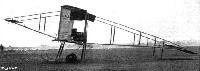
The Neale biplane, with which, as our readers know, experiments have for a long time been conducted on the Brooklands flying ground, is a machine that certainly does embody a method of control that is, so far as we are aware, quite original, and there is little doubt it constitutes one of the most interesting developments in aeroplane construction that is at present on trial. This machine is steered and balanced by movable vertical planes that are hinged to the outermost forward struts of the main planes, and these vertical planes, in conjunction with the fore and aft elevators, constitute the sole controlling organs. Balancing planes were originally fitted to the trailing edges of the upper main plane as a precaution during the initial stages of experiment; but the vertical planes having been found to be entirely satisfactory in their operation, the horizontal balancers were duly abandoned, and the machine now flies with the mechanism for operating them disconnected.
The Neale biplane never possessed a rear rudder, and this peculiarity is the starting point from which the development of the machine in question should be studied; for it may be quite frankly admitted that the principle of control as it now stands, although something of a basic idea, was actually a discovery resulting from practical experiment with the machine. The inventor's fundamental intention was to design an aeroplane that should be an easier machine to fly across the wind than are the majority of modern aeroplanes, which tend to head up into the breeze by the automatic leverage of the rudder in its capacity as a vertical tail. Early gliders employed fixed vertical tail planes for this very purpose, in order to keep them automatically head-on to the wind without any "attention on the part of the pilot; but in a power-driven flyer this particular quality is no longer required, and if evidenced to any marked degree becomes a distinct interference with the control. The original idea out of which the Neale biplane in its present form was evolved may, therefore, be summed up by saying that it was to be a machine without a rear rudder or any sort of vertical tail surface.
The next step was, obviously, to introduce some form of steering apparatus capable of taking the place of a rear rudder, and it was solely for this purpose that the hinged vertical planes were originally placed in the gap between the main planes.
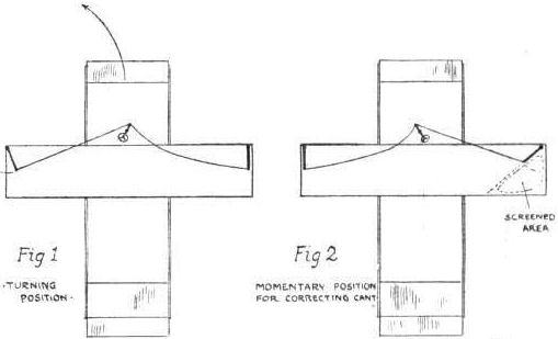
There are two alternative methods of steering an aeroplane in flight, one being to exercise a lateral pressure by means of a rudder, on the end of a long lever such as an outrigger, while the other is to "put the brake on" at one of the extremities of the main planes. It is the latter system that is employed on the Neale biplane. Any plane set at an angle to the line of flight offers resistance, and will, therefore, serve as a brake; the hinged vertical planes in the gap of the Neale biplane are, therefore, primarily brakes. Normally, they are quite free to adjust themselves edge on to the wind, but if either of them is forced into an oblique position the machine slows up on that side and the other extremity wheels round until the pilot once more allows the deflected plane to hang free. Up to the time of writing, these planes, or screen rudders as we have called them for reasons that will be presently obvious, have had a chord of 1 ft. 8 ins., and it has been found in practice that a deflection of 5° has been sufficient to make the machine turn in its own length.
At first these planes were used only as rudders, but it was found by experience that various other effects could be produced by them, and that, in short, they constituted a complete system of lateral control. If one of the planes was smartly deflected to an angle of about 45#, and then as suddenly released, it was found that the machine would heel over without altering its course, and the action was so sure that it was finally adopted as the sole means of balancing, although up to that time horizontal balancers had been inter-connected with the control lever in case of emergency.
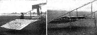
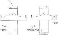
The theory associated with this balancing action is extremely interesting, and is illustrated diagrammatically in one of the accompanying sketches. It is supposed that the sudden deflection of the vertical plane temporarily screens off a very appreciable area of the main plane from the lifting effect of the wind, thus concausing the machine to drop on that side. The success of this manoeuvre depends essentially on the rudder being released immediately after it has been deflected, for if it is held in that position air would be drawn in on the other side and the desired effect neutralised, if not reversed. Should a single operation of the screen be insufficient to entirely restore lateral equilibrium, the operation is repeated in quick succession as often as may be necessary, but inasmuch as it appears to be possible to make the machine heel over to about 45# by a single operation of the screen if properly executed, it is not often that any situation should call for a repetition of the action.
There is yet one other interesting feature associated with the use of these screen rudders. If the action of putting the rudder hard over is performed very quickly indeed, which necessitates quite a strong pull on the control lever, the machine has been found to shift bodily sideways through the air without either canting or swerving. It would appear, therefore, as if this very simple device has quite a number of important possibilities in connection with aeroplane control, and there is no doubt that the further development of the Neale biplane will be watched with the greatest interest in all quarters.
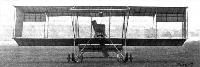
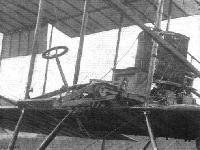
Not unnaturally the features already mentioned overshadow others of a less sensational if nevertheless important character. The Neale biplane itself in its broader characteristics has the appearance of a Farman, and it is mounted on a Farman type wheel and skid chassis. The horizontal tail is a monoplane, and is cambered to carry weight; its trailing portion is hinged and constitutes the rear elevator. This member is interconnected with the front elevator, and is so arranged that its effect is always the superior force. To a certain extent, therefore, these elevators operate automatically, inasmuch as the wind pressure on the rear member serves to adjust the attitude of that in front. The control of the elevators and of the screen rudders is also effected on the Farman principle by a universally-pivoted lever, which in this machine happens to be provided with a wheel, because, in the initial experiment, the rudders were operated by a rotary movement and the horizontal balancers by the sideways action.
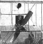
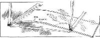
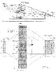
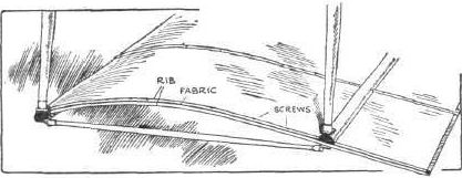
The machine is fitted with a 35-h.p. Green engine, and many tests have been made with different propellers of Mr. Neale's own design, until at last one has been constructed of adequate efficiency to give satisfaction with this comparatively low-powered plant. The propeller in question has a diameter of 7 ft. 9 ins., and an apparent pitch represented by the chord angle of 3 ft. 6 ins. The difficulty has been, as it is in all wooden propellers, to obtain an efficient section through the blade with sufficient strength to prevent warping under pressure. Of the other details of construction we have space only to mention one that forms the subject of the sketch below, showing the method of bracing the fore and aft main transverse spars by straight struts that give the requisite rigidity to the framework to allow very light ribs to be used for cambering the planes. The construction of the planes is also an ingenious method of using a single surface, for each rib consists of two semi-circular sections screwed together with the fabric sandwiched between their flat faces.
Показать полностью