P.Lewis British Aircraft 1809-1914 (Putnam)
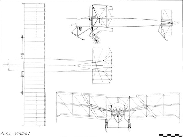
Aeronautical Syndicate Ltd. Viking 1
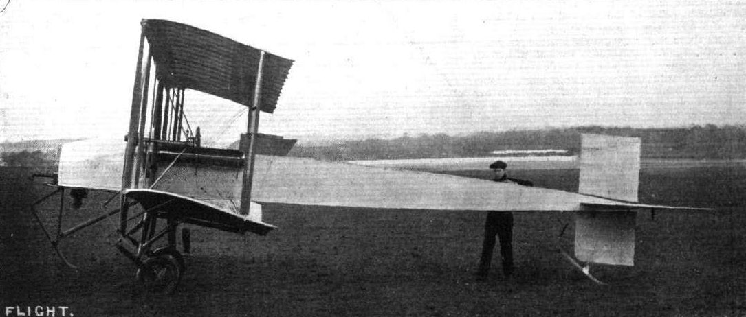
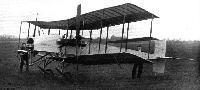
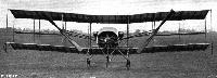
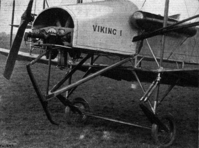
The Viking 1 was designed by Horatio Barber and built by his Aeronautical Syndicate Ltd. at Hendon at the beginning of 1912. The machine was another attempt at producing an aeroplane with two propellers driven from a single fuselage-mounted engine by chains. Power was provided by a 50 h.p. Gnome which was fitted in the nose and which was connected to a pair of large-diameter 8 ft. 6 ins. propellers placed half-way between the wings and about 14 ft. apart. This arrangement necessitated the use of long chains of light weight to transmit the power.
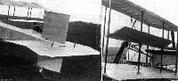
The fuselage was a simple structure of rectangular section with a curved upper decking over the nose portion from the engine back to the cockpit with its side-by-side seating for the two passengers. Parallel-chord wings of three-bay type were used and the fuselage was suspended between them. Several other unusual features were evident in the design, and among them were the 8 ft. 6 ins. x 2 ft. ailerons, which were mounted mid-way between the planes across the three outermost rear interplane struts. The fin was fixed below the rear of the fuselage, and above it was the rudder of almost equal area. Behind the vertical tail surfaces came the one-piece elevator. When on the ground, the Viking was maintained in a near-horizontal position by the long tailskid fitted below the fin. Protection for the nose was provided by a similarly-sprung skid mounted on struts below the engine bay, while smaller skids at the wing-tips served to prevent damage to the propellers in a heavy landing.
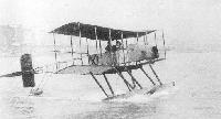
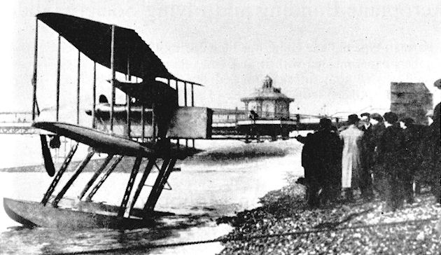
The Viking, known to its designers and others as "Mrs. Grundy", flew well although the twin-propeller arrangement was not a very practical one. It was the last of Barber's designs as, in April, 1912, he decided to retire from active designing and building owing to the cost of keeping up with the rate of progress being made in aviation. He became an aeronautical consultant at 59 Pall Mall, London, S.W.I, and the Aeronautical Syndicate was wound-up, the Viking being sold to Hamilton Ross, the Manager of the Chanter Flying School at Shoreham. On arrival there, it was fitted with floats and the two propellers were replaced with one mounted direct on to the engine in the nose.
SPECIFICATION
Description: Two-seat tractor biplane. Wooden structure, fabric covered.
Manufacturers: Aeronautical Syndicate Ltd., Hendon, London, N.W.9.
Power Plant: 50 h.p. Gnome.
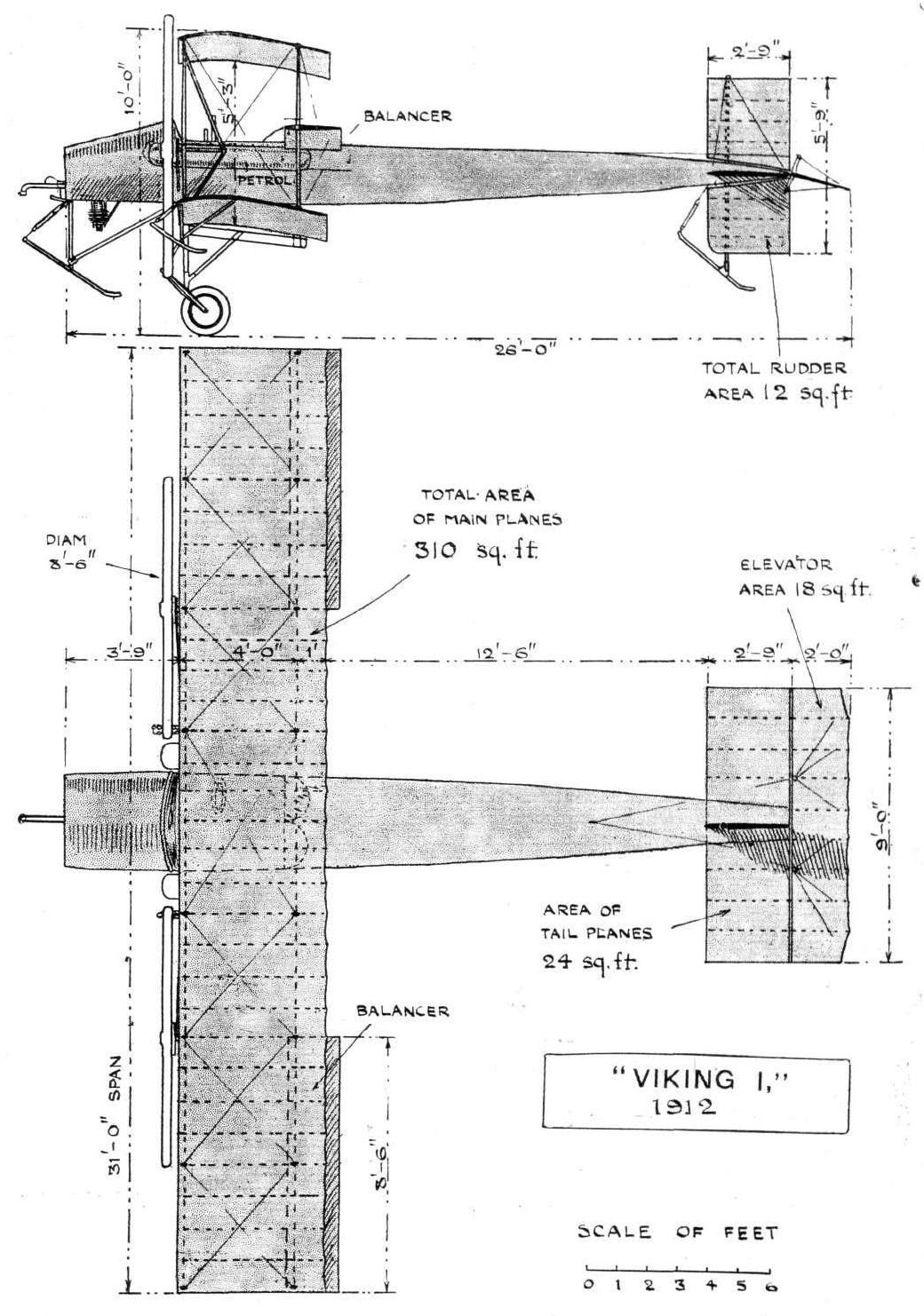
Dimensions: Span, 31 ft. Length, 26 ft. Height, 10 ft. Wing area, 310 sq. ft.
Weights: Empty, 800 lb.
Performance: Cruising speed, 55 m.p.h. Endurance, 6 hrs.
Показать полностью
M.Goodall, A.Tagg British Aircraft before the Great War (Schiffer)
Deleted by request of (c)Schiffer Publishing
ASL VIKING 1 biplane
This was the last design by Horatio Barber and was constructed at Hendon towards the end of 1911. It flew in January 1912 shortly before the closure of the company in April. The pilot and passenger were seated side-by-side behind the rotary engine, which drove the two tractor propellers through chains. Fuel was supplied from two external tanks alongside the cockpit and one in the rear fuselage. The rubber-sprung main undercarriage was supplemented by sprung nose, tail and wing tip skids. The ailerons were mounted on three rear interplane struts. The rudder was above, and the fin below the fuselage.
The first flight was at Hendon on 18 January 1912. The Viking was sold to the Chanter Aviation School at Shoreham, where it was converted into a seaplane. At the same time the twin propeller system was discarded and replaced by a single conventional tractor propeller.
Power: 50hp Gnome driving two 8ft 6in diameter propellers through chains.
Data
Mainplane span 31 ft
Tailplane span 9 ft
Elevator span 9 ft
Mainplane chord 4 ft 6 in
Tailplane chord 2 ft 9 in
Elevator chord 2 ft
Mainplane area 310 sq ft
Foreplane area 24 sq ft
Elevator area 18 sq ft
Length 29 ft 6 in
Cruising speed 55 mph
Endurance 6 hrs
Weight 800 ib
Показать полностью
Журнал Flight
Flight, January 20, 1912.
"VIKING I."
"VIKING I" is a biplane, the first of that type to materialise from the ever-active brain of Mr. H. Barber. Although he has been so long connected with the single-deck type, the germ of this conception was sown long since in the days before he left Salisbury Plain to continue his experimental work in the north of London.
That he should have seen fit to produce such a machine at the present time is yet more evidence of the clearness with which he grasps the ever-changing aspect of the development of aviation in this country, for it is evident to all students that the leading constructors of the world are now concentrating their attention on the development of two types of aeroplanes rather than identifying themselves with a single speciality.
"Viking I" differs from his previous productions in that it flies head first, also it is characterised as a biplane, by the possession of a definite fuselage or covered-in body, which has the engine in front and the pilot's seat just between the main planes. In its detail construction there is that same careful attention to minor matters and sound principle that has given the workmanship of the Aeronautical Syndicate, Ltd., who carry out all Mr. Barber's constructive work in addition to that of their numerous other clients, a leading place in the industry of aeroplane construction. Nor can two opinions exist as to the soundness of the design, whether viewed from the purely aerodynamical standpoint, whether examined in the light of ability to comply with the exacting requirements, or whether considered from the point of view of the pilot's safety.
Consequent with the adoption of the fuselage is the distinctly sound practice of disposing the engine in front of the pilot, a system which was originated in this country and the advantages of which are just becoming apparent to our foreign confreres.
The main body is constructed throughout of silver spruce excepting in the region of the engine, where, in view of the extra strains that are placed upon it, ash is employed. Mounted at its forward extremity, with its inlet pipe extending towards the direction of advance, is the motor, a 50-h.p. Gnome. By means of a short propeller shaft and twin chains arranged Wright-fashion the power is transmitted to the two A.S.L. tractors, that transform into effective thrust the rotary motion of the engine.
A well formed torpedo front of sheet aluminium is arranged over the engine and this together with a slanting screen of the same material at the rear, protects the pilot and passenger from any oil or exhaust fumes thrown off by the motor. Apart from being used for these screens and for the construction of the novel balancers with which the machine is equipped, aluminium has been absolutely discarded as a medium of construction, its place being taken by sheet steel. Throughout its whole length the fuselage is covered in, at the forward end by the metal torpedo front and at the rear by fabric, so that its passage through the air may give rise to a minimum of disturbance.
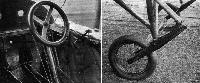
Directly underneath the top surface is the cock-pit, about four feet in length by three feet in width, where are accommodated side by side, the pilot and passenger. The former, who sits on the right-hand side, has before him a vertical wheel, mounted on a vertical column which latter is pivoted at its base so that it can be moved away from or towards the operator. Rotation of the wheel laterally controls the inter-connected balancers on either side, and a to-and-fro movement of the column as a whole controls the attitude of the aeroplane in flight. Placed forward and on either side of the control column is a pair of pedals operating the vertical rudder. In full view of both pilot and passenger is a dashboard where are arranged an altimeter, a compass, a revolution indicator, a watch, and oil and petrol gauges to aid in cross-country work, while, convenient to the right-hand of the pilot are the engine controls. On the control wheel itself is a subsidiary switch by which the engine may be cut off or started again.
Not the least feature of note regarding this section of the machine is the comfort that is afforded the human complement. Constructors, in the midst of abstruse calculations and constructional problems, are apt to overlook such secondary points as this. Not so the Viking engineer, he provides the most comfortable of bucket seats, and completes the snug appearance of the cock-pit by upholstering it in leather, and covering the floor with a square of Turkey carpet.
Tanks for the storage of enough fuel to keep the Gnome motor in operation for six hours are arranged on either side of the body, and glass gauges proceeding from them into the interior keep the pilot well informed as to the actual state of his supply. Feed is by gravity.
At the rear end of the body is disposed the tail-unit whereby control over the machine in the two dimensions of direction and altitude is maintained. Hinged to the rear of a horizontal surface of streamline section, 9 ft. in span by 2 ft. 9 in. in width, is a flap, that serves the function of elevator.
A noticeable feature regarding the design of the tail is that the elevator may be removed by the mere unscrewing of a nut and locknut, and the withdrawal of a single thin steel rod that serves as a common core to the several hinges from which this organ depends. Each side of the flat tail surface is applied to the body much in the same fashion as a monoplane wing, its two booms fitting into sockets, while it is held in correct position by four steel wires. This system commends itself in that the whole of the tail unit can, when necessary, be dismantled in a minimum of time with a minimum of trouble.
Mounted at right angles to the horizontal tail surface is the directional rudder, half above and half below the fuselage. This is pivoted at its average centre of pressure and is operated by means of a crank arranged in the interior of a covered-in body. A small wooden skid, swivelling about the base of the rudder mast and connected to the body at its upper end by means of a shock absorber affords protection for the tail unit against contact with the ground.
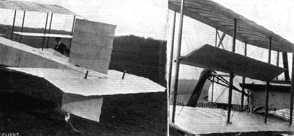
The cellule, 31 ft. in span is composed of two super-imposed single-surfaced planes, separated by a gap of 5 ft. 3 ins. Viewed from the front, its centre section, of 6 ft. span, is horizontal, while the two end sections, each of 12 ft. 6 ins. in span are given a characteristic arched dihedral angle, the horizontal end projection of which is approximately nine inches. Two triangular skeletons of steel tubing, securely mounted between the planes and braced thereto by steel tension wire, support the two tractors, their centres being separated by a distance of 14 ft.
Both planes are perfectly rigid except for a small degree of flexibility that is allowed the trailing edge by virtue of its overhang. Probably the most novel and interesting feature of the machine is the system of balancing employed. The balancers, being arranged at ever-changing angles of incidence, according to the will of the pilot and the conditions of the machine in flight, automatically and simultaneously assume a camber best suited to the angle of incidence at which they are at the moment working. The surfaces of these organs are formed of an aluminium alloy reinforced with spring steel ribs, a clever but simple sliding arrangment allowing for the alteration in the length of the top surface according to whether it is concave or convex. Its conception is so extremely simple that until one remembers that it is usually the most simple things that are the most difficult to discover, one is surprised that it has not been thought of before. The advantages that this system possesses on the score of its efficiency are undoubted. As regards the undercarriage, not only is it of novel design but possesses the attributes of simplicity, adaptability and strength, combined with a low factor of head resistance. Each wheel, as can be seen from one of the photographs, is mounted between a pair of cantilevers, constructed from heavy gauge sheet and channel steel. These latter are universally jointed at their centres to an enormously strong forged steel fitting, to which are assembled the ash chassis struts proceeding from the lower plane. The upper end of each cantilever is anchored to the body of the machine by a pair of rubber shock absorbers. Uniting the two wheels is a tie rod, and diagonal wires carrying miniature shock absorbers are intoduced to keep them parallel to the geometrical axis of the machine. To prevent any damage resulting from too steep a landing a skid is fitted to the extreme nose of the body and two similar skids, but of smaller dimensions, are arranged at each end of the cellule to protect the wing tips. These are allowed universal motion and are governed by shock-absorbers.
Weighing 800 lbs., the machine has been designed for a speed of 55 miles per hour, and to carry its double human load for a non-stop flight of six hours. In the matter of speed, the intentions of the designer have been more than realised, for in practical tests that have recently taken place, this 55 miles has been handsomely exceeded. The Viking biplane undoubtedly represents a considerable advance en the admittedly sound work of the A.S.L. establishment, and if sheer merit goes for anything these days, it should pave the way for an exceedingly prosperous business year.
Показать полностью