P.Lewis British Aircraft 1809-1914 (Putnam)
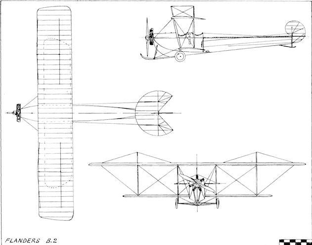
Flanders B.2
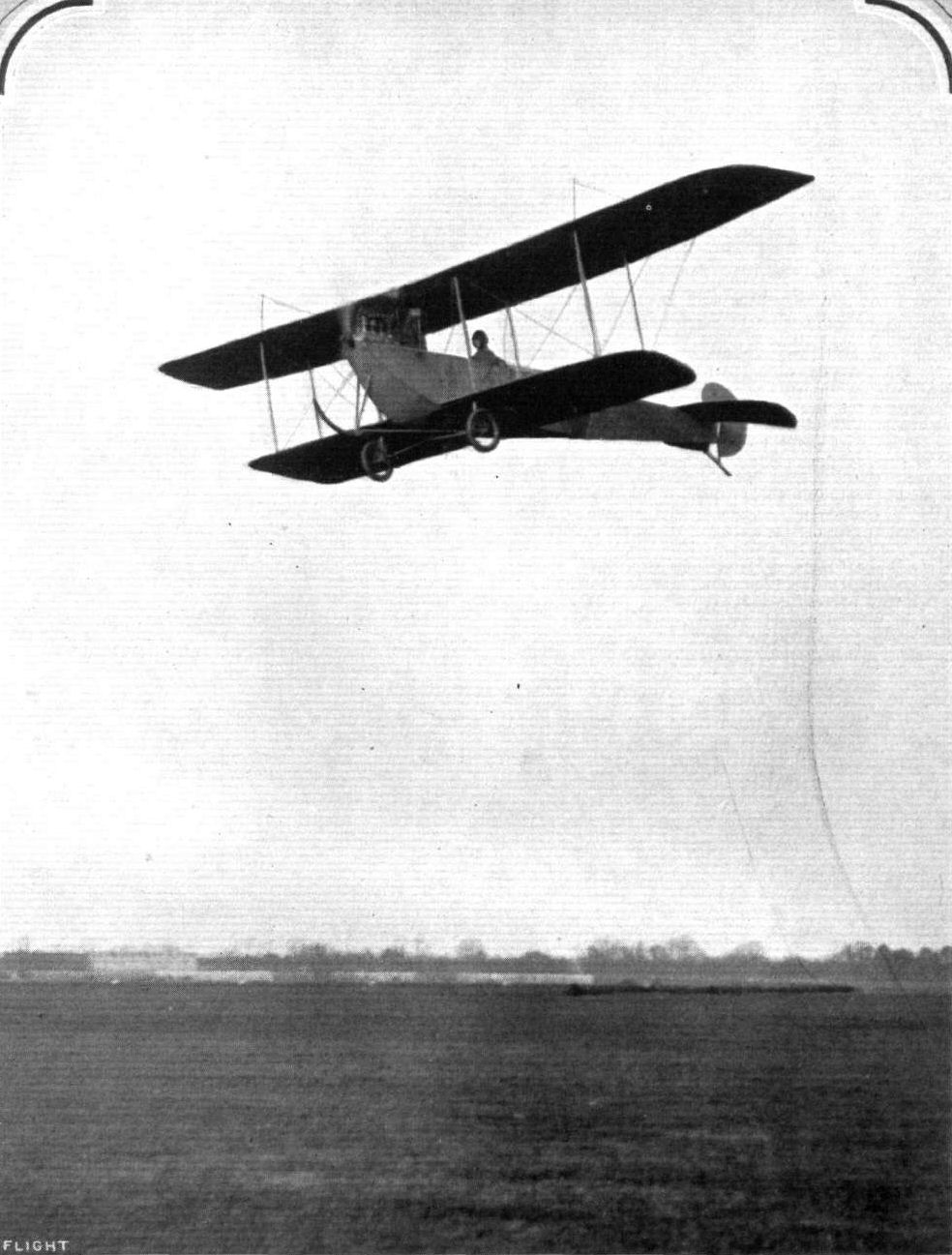
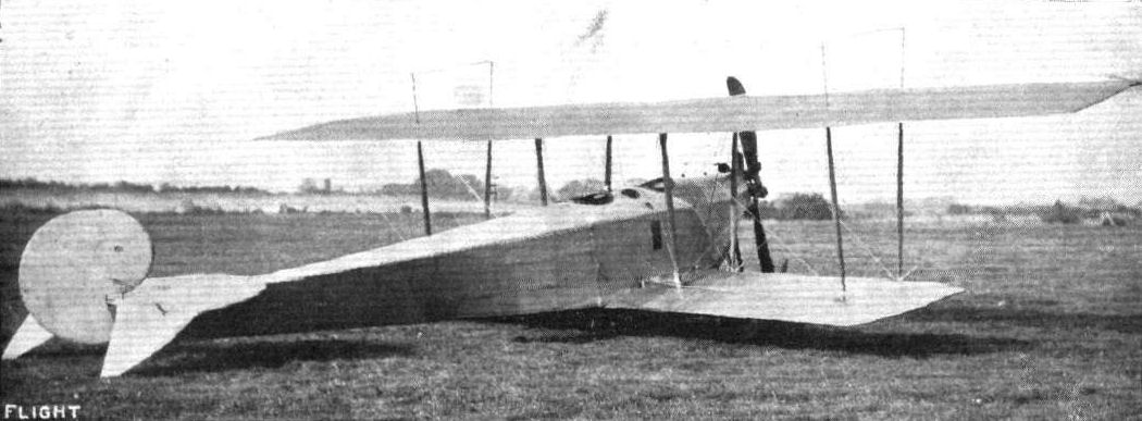
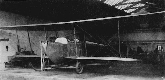
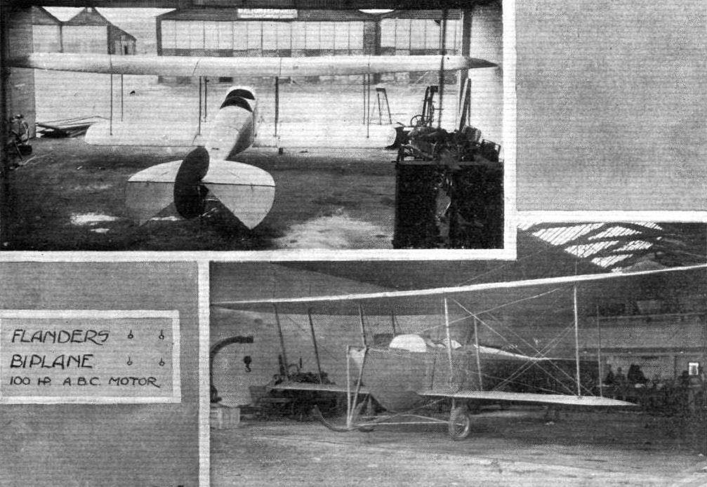
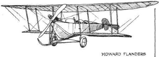
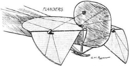
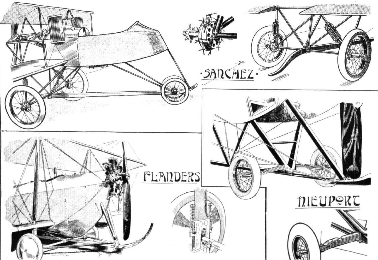
A tractor biplane design was drawn up by R. L. Howard Flanders for participation in the 1912 Military Trials. The power plant chosen was the eight-cylinder 100 h.p. A.B.C., coupled to an 8 ft. 6 ins. diameter Regy propeller. The machine possessed pleasingly clean lines, and was characterized by the depth of its fuselage about the cockpit area and by the shortness of its undercarriage, which was brought about by the high thrust-line, all of which combined to give a very low-set appearance on the ground. The fore-portion of the fuselage was of pentagon section, surmounted by a curved decking; mid-way along the body, the section changed from rectangular to triangular as the fuselage tapered towards the tail. The deep cockpits made the machine very comfortable, as the heads only of the occupants were exposed; the pilot sat in the rearmost of the pair of tandem seats.
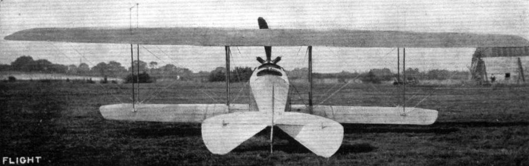
The wing bays were unconventional in that they were formed by upper and lower wings connected by four pairs of parallel interplane struts, centre-section struts being omitted. Dihedral also was lacking, but washout was applied at the tips, and prominent king-posts supported the overhang of the 43 ft. span upper wings.
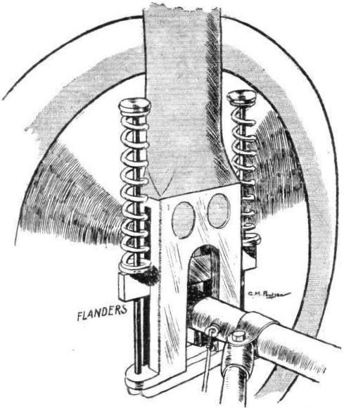
The undercarriage supported the machine in a near-horizontal position on the ground, shock-absorbing being taken by vertical movement of the neat coil springs on the main upright legs. The wheels were mounted on a transverse axle, and a curved skid afforded protection to the propeller.
F. P. Raynham was nominated to fly the Flanders Biplane at the Trials, in which it was entry No. 16, but was unable to do so, as the machine arrived without its engine owing to delay in delivery of the eight cylinder 100 h.p. A.B.C. with which it was to be fitted. After one short hop at the Trials it was taken back to Brooklands, where, some four months later, a 40 h.p. A.B.C. was installed on 21st December, 1912. On 22nd of the month the aircraft was test-flown by Raynham, who also coaxed it into the air quite happily with A. Dukinlield-Jones and C. Lavzell-Apps on board at the same time. A week later, on 29th December, the biplane ran into a fence and damaged its wings. Its designer had already decided to replace them by an improved set, and this was done accordingly.
The new wings were of a shorter upper span of 41 ft. and were reduced in area from 400 sq. ft. to 395 sq. ft. The upper tips had their outward rake reduced, while the lower wings' square-cut tips were tapered inwards. The interplane struts were altered to splay outwards at the top, and although ailerons had been scheduled in place of warping to reduce spar fatigue, warping was still embodied in the design.
Raynham continued to fly the machine during the spring of 1913, and for a short time early in the year an experimental rudder was fitted which was divided vertically into two surfaces hinged to the post, both halves being opened from the cockpit sideways across the airflow so that they operated as air-brakes. The scheme was not successful, and the original rudder was re-installed.
It was decided that the biplane could use extra power, so, in October, 1913, the A.B.C. was removed and its place was taken by a seven-cylinder 60 h.p. Isaacson radial driving an 8 ft. 6 ins. diameter Lang propeller. Maximum speed was increased by nearly 10 m.p.h. from 56 m.p.h. with the 40 h.p. A.B.C. to 65 m.p.h. with the new engine. A. Dukinfield-Jones often piloted the machine at Brooklands. and found it to be a very pleasant aeroplane to handle.
In May, 1914, Lt. R. E. B. Hunt was reported to have bought the Flanders B.2, and in June of the same year another change of engine was made when yet more power was added with the fitting of the seven-cylinder 70 h.p. Gnome rotary complete with a cowling. The tail unit was revised to incorporate a fin. In this form, the Flanders B.2 was bought by the Admiralty at the commencement of the 1914-18 War, and was used as No. 918 at Great Yarmouth by the R.N.A.S.
SPECIFICATION
Description: Two-seat tractor biplane. Wooden structure, fabric covered.
Manufacturers: L. Howard Flanders, Ltd., Richmond and Brooklands, Surrey.
Power Plant: 100 h.p. A.B.C., 40 h.p. A.B.C., 60 h.p. Isaacson, 70 h.p. Gnome.
Dimensions:
(40 h.p. A.B.C.) Span, 43 ft. Length, 31 ft. 6 ins. Wing area, 400 sq. ft.;
(60 h.p. Isaacson) Span, 41 ft. Length, 31 ft. 10 ins. Wing area, 395 sq. ft.;
(70 h.p. Gnome) Span, 40 ft. Length, 31 ft. Wing area, 390 sq. ft.
Weights:
(40 h.p. A.B.C.) Empty, 670 lb. Loaded, 1,100 lb.;
(60 h.p. Isaacson) Empty, 1,000 lb. Loaded, 1,571 lb.;
(70 h.p. Gnome) Empty, 1,050 lb. Loaded, 1,650 lb.
Performance:
(40 h.p. A.B.C.) Maximum speed, 56 m.p.h. Landing speed, 38 m.p.h.;
(60 h.p. Isaacson) Maximum speed, 65 m.p.h. Landing speed, 40 m.p.h.;
(70 h.p. Gnome) Maximum speed, 68 m.p.h. Landing speed, 40 m.p.h. Endurance, 4*5 hrs.
Показать полностью
M.Goodall, A.Tagg British Aircraft before the Great War (Schiffer)
Deleted by request of (c)Schiffer Publishing
FLANDERS B.2 biplane
The ABC engine intended for the biplane built for the Military Trials of August 1912, was not ready in time to be fitted, so the machine was towed, without its power unit to Larkhill. The undercarriage of the machine, No. 14 in the trials, was damaged on the way. After repairs, the aircraft took part in the assembly test and subsequently the engine was fitted. After a brief test, mechanical trouble developed, described as a 'tied-up camshaft' caused by a stripped timing gear, and the aircraft was withdrawn.
The bottom of the fuselage was basically of triangular section with a full-length keel, changing to rectangular in the forward area, to a position behind the rear cockpit, where the bottom longerons joined to the central keel. A rounded decking ran the full length of the top.
The wings were of two bays with top wing overhang, braced by cables to kingposts above the outer interplane struts. The front inboard struts were of strong ash to carry the loads from the undercarriage, which was mounted immediately below. The axle was sprung and moved in slots in the vertical members, being restrained by a tubular member with a pivot on a vee strut below the engine, which also served to mount a long curved central skid.
Lateral control by warping of both top and bottom wings was operated by cables and pulleys. A conventional tail unit included an aerodynamically balanced rudder of comma shape.
Subsequently a 40hp ABC was installed and the machine flew with this for the first time on 22 December 1912, piloted by Raynham, and later also with two passengers in its capacious fuselage. On 29 December 1912 the aircraft was damaged and the wings were then replaced with ones of slightly less span and altered tip shape. A split rudder to serve as an air brake was tried in the spring of 1913, but was soon discarded. In October 1913 a 60hp Isaacson radial replaced the ABC and an improved performance resulted.
A further engine change was made in June 1914, after it was reported that Lt. R.E.B. Hunt RN had bought the machine, with the fitting of a 70hp Gnome in a circular cowling, with cutaway lower portion. A fin and new rudder were also fitted. The Flanders biplane was taken over by the Admiralty at the outbreak of war, becoming serial No.918 in the RNAS until deleted in January 1915.
Power:
(1) 100hp ABC eight-cylinder, water-cooled vee driving a 8ft 6in dia Regy propeller.
(2) 40hp ABC four-cylinder inline, water-cooled.
(3) 60hp Isaacson seven-cylinder, air-cooled radial driving a 8ft 6in dia Lang propeller
(4) 70hp Gnome seven-cylinder, air-cooled rotary.
Data Version (1) (2) (3) (4)
Span top 43ft 43ft 41ft 40ft
Span bottom 27ft 27ft 27ft 27ft
Chord top 6ft 7in 6ft 7in 6ft 7in 6ft 7in
Chord bottom 5ft 1in 5ft 1in 5ft 1in 5ft 1in
Area wings 400 sq ft 400 sq ft 400 sq ft 400 sq ft
Area tailplane 28 sq ft 28 sq ft 28 sq ft
Area elevators 14 sq ft 14 sq ft 14 sq ft
Length 31ft 6in* 31ft 6in 31ft 10in 31ft
Weight 1,250 lb 670 lb 1,000 lb 1,050 lb
Weight allup 2,000 lb 1,100lb 1,571lb 1,650 lb
Speed (mph) 65 (est.) 38-56 40-65 40-68
* The Aero reported 30ft 6in
Показать полностью
J.Bruce British Aeroplanes 1914-1918 (Putnam)
Flanders B.2
L. HOWARD FLANDERS was one of Britain’s pioneer aircraft constructors. In November, 1909, . he joined J. V. Neale as manager, and gained valuable practical experience with the early Neale aircraft. In 1911 he designed and built a handsome monoplane powered by a 60 h.p. Green engine; this machine was quite successful. In 1912 the War Office ordered four Flanders monoplanes of an improved type, powered by the 70 h.p. Renault engine. These machines were complete and about to be handed over to the R.F.C. when the infamous “monoplane ban” came into force.
The British Military Trials were held on Salisbury Plain in 1912, and one of the entrants was a biplane of Flanders design. Unfortunately, the biplane did not receive its engine, a 100 h.p. A.B.C., in time to enable it to compete in the flying tests. It was later fitted with a 40 h.p. A.B.C. engine, and flew well despite the small amount of power available. The designed speed of the Flanders biplane with the 100 h.p. engine was 83 m.p.h., and it caused a minor sensation by flying at 55 m.p.h. with three people on board when fitted with the 40 h.p. engine.
In the autumn of 1913 the aircraft was fitted with the 60 h.p. Isaacson seven-cylinder radial engine, which proved to be a very satisfactory power unit. In this form the Flanders B.2 flew frequently and well in the hands of A. Dukinfield-Jones.
The Flanders biplane had several unusual structural features. As the illustration shows, the fuselage was remarkably deep. It had a single central longeron forming a kind of keel along its underside; behind the cockpits the fuselage tapered to a triangular cross-section at the tail. All the longerons in the nose were of hickory, and in the rear portion of the fuselage they were of ash. The passenger occupied the front cockpit, from which he had a good view in forward and downward directions.
The central skid of the undercarriage was made of hickory, and was spliced to the keel of the fuselage. Each wheel was on a separate half-axle hinged at its inner end to the central skid. Independent springing was provided by means of twin coil springs in compression on each leg of the undercarriage.
The wings were of unequal span and chord, and were characterised by the absence of any conventional centre-section bracing. The spars of the wing panels were spruce, whilst those of the centre-section were of ash. Lateral control was by wing-warping.
The tailplane was a semi-circular surface, and the rudder was strikingly similar to that of the Avro 504.
By June, 1914, the Flanders B.2 had been fitted with yet another engine. The new power unit was a 70 h.p. Gnome rotary which had been modified to have the valves of an 80 h.p. Gnome.
On the outbreak of war the machine was bought by the Admiralty and was allocated to the R.N.A.S. station at Great Yarmouth. The delivery flight was punctuated by a series of forced landings, after one of which the machine was dismantled with more vigour than care, and was delivered at Yarmouth in pieces.
It was intended to scrap the Flanders, but Lieutenant R. J. Bone ordered the machine to be rebuilt. New spars were fitted to the wings and new fabric was applied, and the aircraft was rigged by reference to a photograph which showed it in its original state. Lieutenant Bone tested the Flanders, but it proved to be tail-heavy. A new and larger tailplane was therefore designed and made in the station workshop, and with it the machine was passed as fit for use. There is no record that the Flanders biplane was ever flown in any operational capacity, however.
SPECIFICATION
Manufacturer: L. Howard Flanders, Brooklands, Byfleet.
Power: 40 h.p. A.B.C.; 60 h.p. Isaacson; 70 h.p. Gnome.
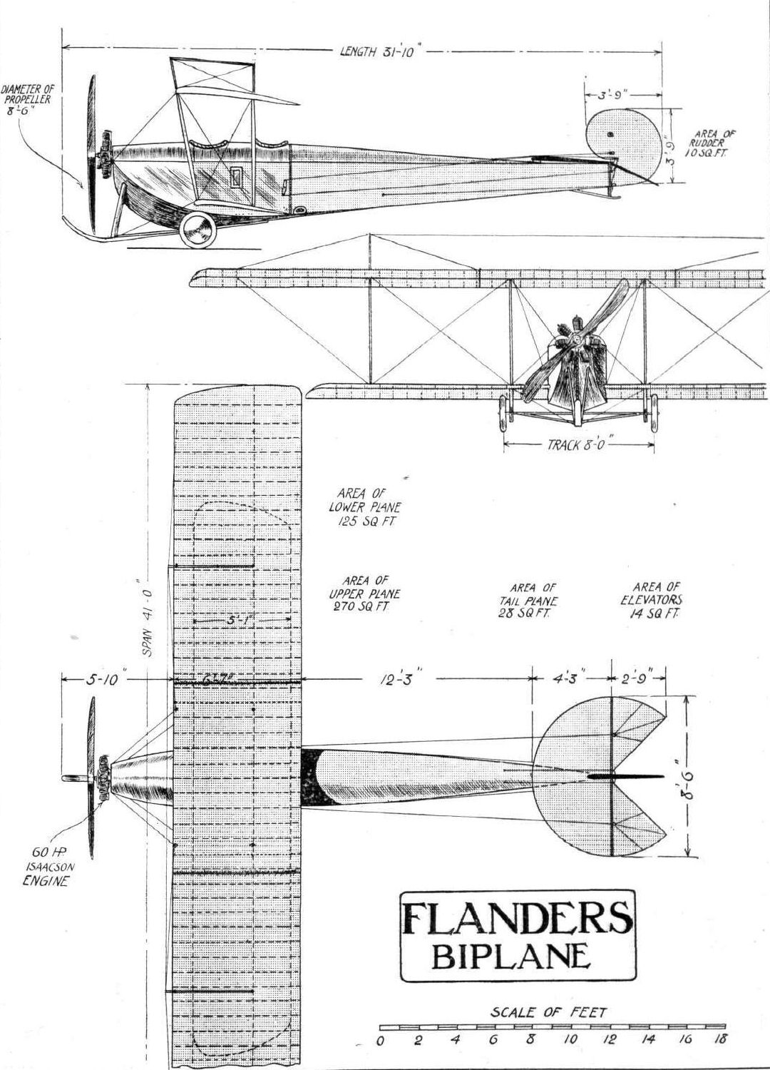
Dimensions: Span: upper 41 ft, lower 29 ft. Length: 31 ft 10 in. Chord: upper 6 ft 7 in., lower 5 ft 1 in. Dihedral: nil. Span of tail: 8 ft 6 in. Wheel track: 8 ft. Airscrew diameter: 8 ft 6 in.
Areas: Wings: upper 270 sq ft, lower 125 sq ft, total 395 sq ft. Tailplane: 28 sq ft. Elevators: 14 sq ft. Rudder: 10 sq ft.
Weights: 40 h.p. A.B.C. - Empty: 670 lb. Loaded: 1,110 lb. Isaacson - Empty: 1,000 lb. Loaded: 1,571 lb.
Performance: 40 h.p. A.B.C. - Maximum speed: 56 m.p.h. Initial rate of climb: 200 feet per minute. Isaacson - Maximum speed: 65 m.p.h. Endurance: 4 1/2 hours.
Tankage: Main (pressure) tank: 15 gallons; service (gravity) tank: 7 gallons; total: 22 gallons.
Service Use: Flown at R.N.A.S. Station, Great Yarmouth.
Serial Number: 918.
Показать полностью
Jane's All The World Aircraft 1913
HOWARD-FLANDERS. L. Howard-Flanders, Ltd., 31, Townsend Terrace, Richmond, Surrey. School: Brooklands. Established February, 1912, by Howard-Flanders, whose connection with aviation dates from the pioneer days. Richmond Works opened April, 1912. Capacity of the works at end of 1912 was sufficient to turn out from 25 to 35 machines a year.
F 4 1912. B 2 1912. S 2 1913. F 5 1913. B 3 1913.
2-seater 2-seater single-seat 2-seater 2-seater
military biplane. monoplane. monoplane. biplane.
monoplane.
Length...feet(m) 31? (9.50) 31? (9.50) 28 (8.50) 31 (9.45) 31 (9.45)
Span....feet(m) 40 (12) 40 (12) 35 (10.70) 39 (11.90) 40 (12)
Are..sq.ft.(m?) 240 (22) 390 (36) 190 (17.75) 250 (30) 390 (36)
Weight,total...
.......lbs.(kgs) 1850 (839) 1500 (680) 1180 (585) 1600 (726) 1650 (748)
Weight, useful...
......lbs.(kgs) 500 (227) 450 (204) 350 (159) 600 (272) 600 (272)
Motor......h.p. 70 Renault 40 A.B.C. 80 Gnome 80 Gnome 80 Gnome
Speed, max...
.....m.p.h.(km) 67 (108) 56 (90) 82 (132) 70 (115) 68 (110)
Speed, min...
.....m.p.h.(km) 41 (66) 38 (61 ) 45 (73) 42 (68) 40 (65)
Number built
during 1912 4 1 - - -
Remarks.--F 4 climbing speed 1000 feet (305 m.) in 3? minutes, 1500 in 5? mins., 2000 in 8 mins. B 2 climbing speed 200 feet (61 m.) per minute.
The four F 4 type were bought by the British Army during 1912.
Показать полностью
Журнал Flight
Flight, August 3, 1912.
THE MILITARY AEROPLANE COMPETITION.
THE MACHINES.
THE FLANDERS BIPLANE.
A BIPLANE built by one of our manufacturers who has hitherto been known only by monoplanes of his construction must of necessity be interesting. Although in details it bears some resemblance to the monoplanes, in general ideas it is naturally dissimilar.
The first feature one would notice is the fuselage. This, in the front, is of great depth, extending down to the axle of the landing gear. In shape it is rather difficult to describe, consisting of a square whose topside is converted into a semi-circle, and on whose bottom side there stands a triangle. This section continues until about half way to the tail, when it is simply triangular. In front the semi-circular portion is, of course, cut away into gaps, from which the pilot's and passenger's heads protrude. The end of the lower triangular portion is coincident with the continuation of the front skid, which is of great length and extends half-way down the fuselage. The bottom of the square portion acts as a floor for the interior of the machine.
The planes, of which the top one is the larger (42 ft. as against 27 ft.), are decale or staggered, but for no aerodynamic reasons. The planes have been so arranged from purely constructional motives. Amongst other reasons is the fact that it enables one of the inter-plane struts to be continued as a vertical strut for the landing-chassis, and it also means that the passenger has an excellent view of the ground beneath him.
The pilot and passenger sit in tandem, and as regards width of fuselage there is no reason why there should not be two passengers if occasion arose.
Both planes are capable of being warped, though the higher one has the greater effect, both because it is of greater span, and because in its plan form it is longer at the trailing edge than it is at the leading edge.
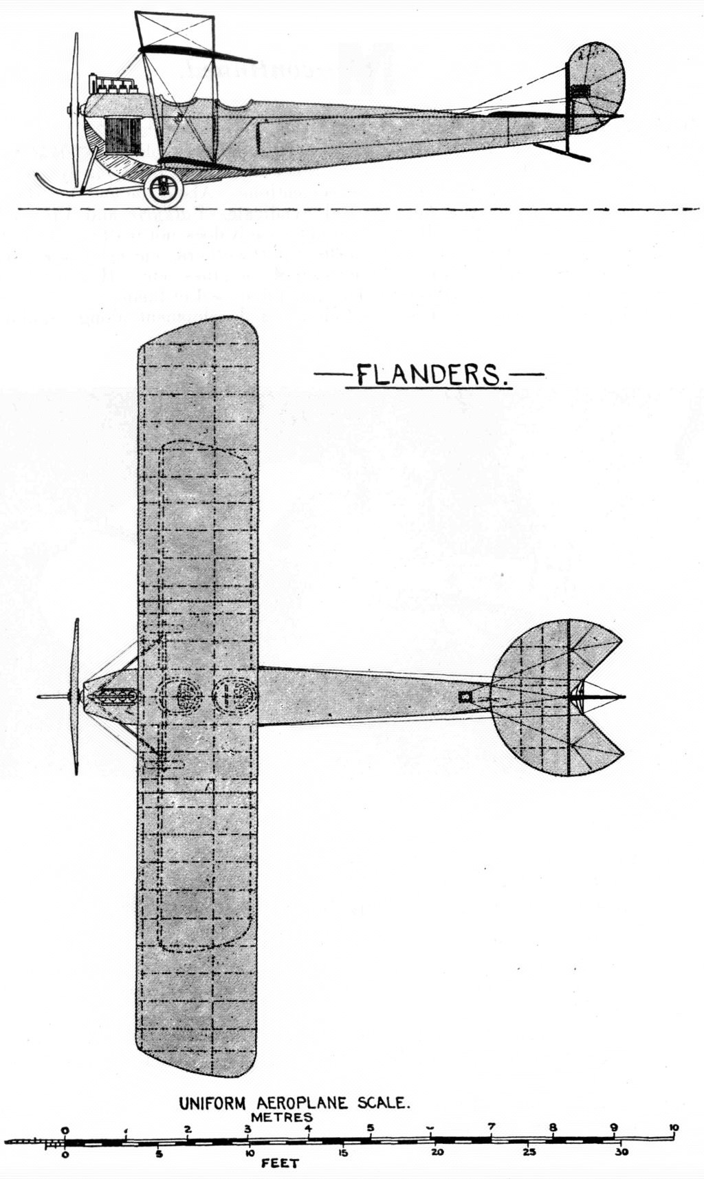
The tail and empennage, as can be seen from the photograph, are the same as those previously employed in the monoplanes, consisting of a non-lifting tail, cambered on the top surface, and a balanced rudder.
The landing chassis is of the simplest kind, consisting as it does of a long skid extending far back, a pair of internal vertical struts, and another pair of vertical struts beyond the fuselage and adjacent to the propeller. The cross axle carries a pair of wheels with tyres of a large size, and is pivoted to the middle of the skid. Sideways and vertical movement is corrected by a pair of compression springs. When these are strained to the maximum there is still a clearance of twelve inches between the lower plane and the top of the wheel. The engine is a 100-h.p. A.B.C. If this engine does as well as its smaller prototype (the 40-h.p. on the Burgess-Wright) the whole machine should be a great success.
Flight, October 25, 1913.
THE FLANDERSJBIPLANE.
AFTER a number of delays, due to no inherent fault in the machine itself, the Flanders biplane has proved that it possesses all the good qualities looked for in a machine, which is the product of so able a designer as Mr. L. Howard Flanders, whose name has in the past been more generally associated with the construction of monoplanes. Unfortunately Mr. Flanders cannot be present to witness the excellent flying now done by the machine of his creation, as he has been ordered by his doctor to go for a six months' trip to Australia, in order to recuperate after his recent motor smash. We feel certain that all our readers will join us in wishing Mr. Flanders a speedy recovery.
As for the machine itself, one of the first characteristics noticed is the extremely deep fuselage. On closer inspection the shape of that member is rather unusual, being of pentagonal section in the front portion and tapering away to a triangular cross section at the rear. The lower longeron or keel of the fuselage runs right through from bow to stern, as do also the two upper longerons. The lower longerons starting from the nose of the machine curve down abruptly to form the sides of the rectangular portion of the fuselage, and form a spliced joint with the keel about six feet to the rear of the pilot's seat. The longerons are of hickory in the front portion where the weight is concentrated, and where consequently the greatest strength is required, whilst in the rear the longerons are made of ash. The struts and cross members are of ash in front and of spruce behind, the whole being made rigid in the usual way by diagonal cross wiring. A turtle back formed by longitudinal stringers, and having its highest point in the neighbourhood of the pilot's seat, from where it gradually flattens out towards the tail plane, gives a neat appearance to the top of the fuselage as well as affording protection against the flow of air, as only the pilot's and passenger's heads project above the turtle back.
Another point which characterises this interesting machine is the peculiar arrangement of the main planes, the upper one of which is of considerably greater chord than the lower one, and being furthermore staggered forward. It will be noticed that this is obtained by having the rear struts at right angles to the line of flight whilst the front struts slope forward.
From the front elevation of the machine it will be seen that there is a considerable overhang to the upper plane, the weight of which, when the machine is on the ground, is taken by top bracing wires carried over king posts. Both top and bottom planes are straight, i.e. there is no dihedral angle, but the angle of incidence diminishes towards the tips of the planes, thus forming a pronounced "wash out." With the exception of the two inner plane struts, which serve to support the chassis struts and therefore are made of ash, the plane struts are all made of solid spruce. The wings are built up of spars of I section, ash being the material employed in the centre portion, while the outer part is made of spruce. The ribs have webs of white pine with flanges of ash, the whole being bound with fabric to prevent the wood from splitting. In the present machine wing warping is employed for maintenance of lateral stability, but the next machine will be fitted with ailerons, which has the advantage of doing away with the constant twisting of the wing spars, which may in time cause fatigue.
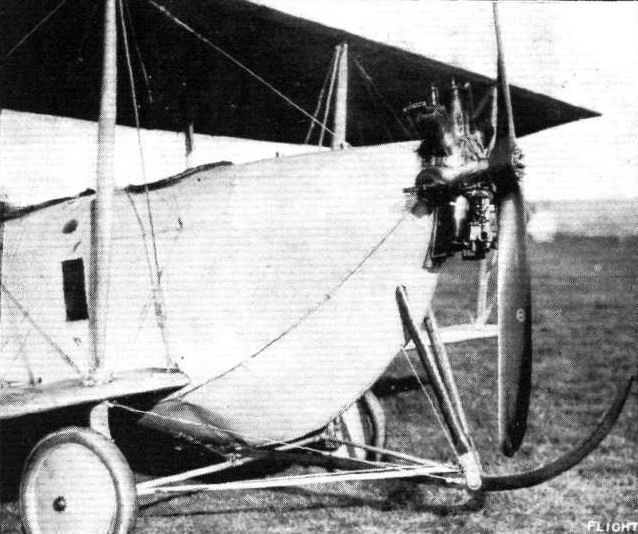
A hickory skid secured to the keel of the fuselage and running parallel to it is supported in front by a pair of V struts sloping down from the upper longerons of the fuselage. Anchored to the keel are the two portions of the divided axle, which carries on its extreme ends the two landing wheels. The method of springing these is shown in one of the accompanying sketches, which is, we think, self-explanatory. It will be noticed that the whole landing chassis is extremely simple, and offers a minimum of head resistance, while at the same time it is quite efficient. Owing to the proximity of the lower plane to the ground there is a certain cushioning effect in landing which greatly facilitates that operation.
Mounted on the rear of the fuselage are the tail planes which are of the same type as those characteristic of the Flanders monoplane and consisting of a fixed tail plane of semi-circular shape to the trailing edge of which are hinged the elevator planes, and of a rudder composed of, roughly speaking, two semi-circular surfaces of which the upper and smaller one is in front of the pivoting point. Double stranded cables pass from the crank levers on the rudder and elevators to the control levers in front of the pilot's seat. A tail skid of very simple construction prevents the tail planes from coming in contact with the ground.
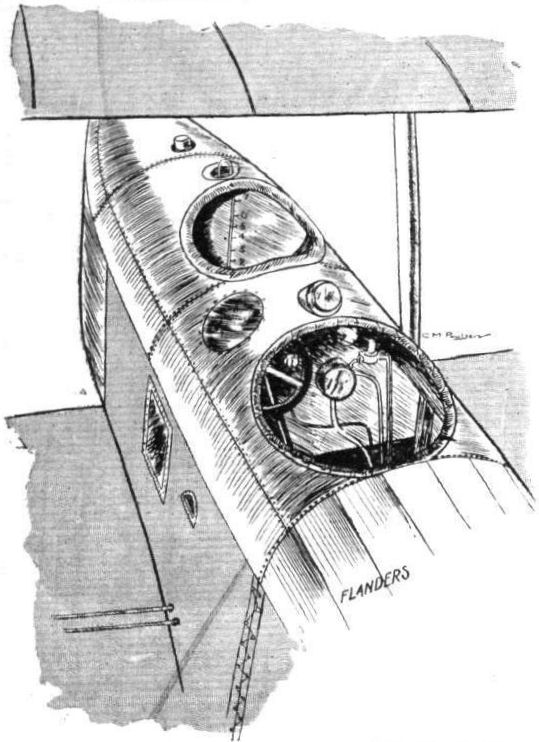
Inside the very deep fuselage are the pilot's and passenger's seats, arranged tandem fashion, the passenger occupying the front seat, from where he has an exceptionally fine view of the ground below, situated as he is well out in front of the lower plane. In front of him is a petrol service tank with a capacity of 7 gallons, or sufficient for a flight of an hour and a half. Under the passenger's seat is another tank with a capacity of 15 gallons, petrol being transferred from this to the service tank by means of a pressure pump. On a dash in front of the pilot are mounted the revolution indicator, oil pressure gauge, petrol pressure gauge, tell-tale oil glass, air-speed indicator, clock and compass, while on top of the fuselage is mounted an altimeter.
Secured to the nose of the fuselage is the overhung engine, a 60 h.p. Isaacson radial stationary motor, driving directly a Lang propeller of 8 ft. 6 ins. diameter, 5 ft. 6 ins. pitch. After having been overhauled at the Isaacson works at Leeds, this engine is now giving entire satisfaction, having apparently been cured of all the little troubles always experienced in a new engine, and judging from the way it takes the biplane off the ground after a very short run it develops at least all its rated horse power. Certainly, as fitted to the Flanders biplane, it is entirely satisfactory, and it is to be hoped that it will soon gain the popularity that it certainly deserves.
In the hands of Mr. A. Dukinfield Jones, the Flanders biplane is now flying extremely well, getting off in a remarkably short space and climbing at a very steep angle, while her flying speed must be in the neighbourhood of 60 miles per hour. The weight of the machine empty is 1,000 lbs.
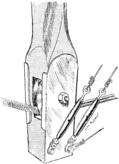
An interesting point in connection with the warping of the wings is the fact that the warping cable passes right through from wing to wing, a branch cable being joined to the main cable outside the fuselage and terminating in short lengths of chain which pass round sprockets on the control wheel, operating the warp, so that should these branch cables break, the main cable will still be carrying its load, and the pilot would have a chance of being able to glide down safely, although he would not, of course, be able to use his warp.
Duralumin has been used in the construction of the machine for radius rods, wing-spar clips, rudder and elevator crank levers, and most of the strut joints. The planes are covered with Hewittson's fabric and doped with Cellon.
Flight, October 29, 1915.
CONSTRUCTIONAL DETAILS.-VIII.
<...>
Somewhat unusual in arrangement was the undercarriage of the old Flanders biplane shown in one of our sketches. This chassis, it will be seen, is extremely simple, and offers a minimum of head resistance. The body is very deep in front and of pentagonal section, so that the hickory skid can be fastened directly to the lower fuselage member. Anchored to the keel are the two stub axles that carry the wheels. The method of springing is shown in the detail sketch, which is, we think, self-explanatory.
<...>
Показать полностью