P.Lewis British Aircraft 1809-1914 (Putnam)
Parsons Biplane
The Parsons Biplane was designed and built by P. M. Muller specially to make use of an automobile engine the greater weight of which, compared with the light-weight aero engines, normally militated against its use in an aeroplane, where every pound was a consideration.
A two-seat tractor constructed early in 1913, the Parsons Biplane was fitted with the four-cylinder 40 h.p. Aster car engine, which had been lightened slightly and which drove an 8 ft. 2 ins. diameter Normale propeller.
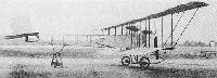
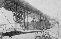
The design embodied several original features in the hope that stability would thereby be improved. Among them was the extended flexible trailing-edge of the upper wings with considerable overhang of the lower planes. Another was that the fore-part only of the fuselage was covered, in support of the theory that the open framework at the rear would render the rudder more effective. The interplane struts were set close together towards the leading-edge of the wings, thus helping towards the flexing of the rear portion of the chord in the supposed interests of lateral stability. The undercarriage was a straightforward unit of a pair of wheels and twin skids.
The machine was tested at Brooklands by John Alcock and Jack Humphreys, making a cross-country flight at 2,000 ft. from the aerodrome during May, 1913, when piloted by Alcock.
Another odd device tried out on the biplane was the J. G. Parsons Pendulum Stabilizer, which consisted of a pair of paddle-wheels, one being suspended in the gap between each pair of wing-tips. The Aster engine installation was not found to be successful and was replaced by a conventional aero engine, the 70 h.p Gnome. In September, 1913, the Parsons Biplane was bought by Noel Pemberton Billing, some of its components forming later part of the Gaskell-Blackburn Biplane of 1914.
SPECIFICATION
Description: Two-seat tractor biplane. Wooden structure, fabric covered.
Manufacturer: P. M. Muller.
Power Plant: 40 h.p. Aster, 70 h.p. Gnome.
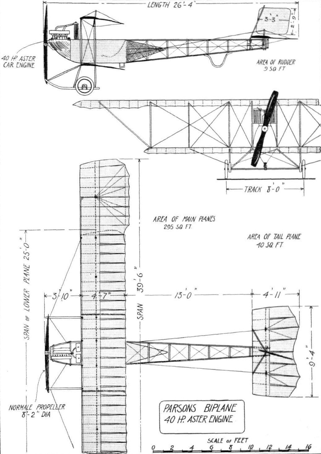
Dimensions: Span, 39 ft. 6 ins. Length, 26 ft. 4 ins. Wing area, 295 sq. ft.
Показать полностью
M.Goodall, A.Tagg British Aircraft before the Great War (Schiffer)
Deleted by request of (c)Schiffer Publishing
PARSONS biplane (J.G. Parsons and Percy Maxwell Muller, Shed No.6, Brooklands)
P.M. Muller, who later became manager of Vickers at Brooklands in wartime, designed and built this biplane primarily for testing the Parsons Pendulum Paddle-Wheel Stabilizer. The machine was flown in May 1913, by John Alcock, later of Atlantic crossing fame, and also by Jack Humphries, without the stabilizer fitted; although using a heavy car engine weighing 400 lb. with radiators, the machine flew well reaching 1500 feet in twenty minutes. The stabilizers, which were mounted in the gap between each wingtip, were presumably tried and found wanting, as was the Aster engine, for it was replaced in August by a Gnome.
Alcock was involved in a collision on the ground with the Champel biplane on 4 August 1913, in spite of which he started soon after in a race, but was soon forced to land. In September the machine was sold to a recent pupil of the Bristol School named Boger, who crashed it on 11 December 1913 at Ripley, when attempting to land there to breakfast at the Talbot Hotel. The remains were bought by Pemberton Billing and some parts were used in the construction of the Gaskell-Blackbum biplane.
Some features of the Caudron were embodied in the Parsons. The wing structure in particular employing closely spaced interplane struts and a similar system of warping of the top outer wing panels. Flexing of the tailplane for control, instead of a separate elevator, was also similar to the Caudron.
The fuselage was an ash and spruce girder, fabric covered in the area of the pilot's seat with the fabric tapering to a cone shape inside the structure, which was open back to the tail. The main undercarriage had a wide track and consisted of six ash struts and twin skids with a rubber cord sprung axle. The tail was supported by a cane, hoop-shaped tail skid. The engine was cooled by two radiators mounted behind, partially in the fuselage, behind which were fuel and oil tanks, followed by the pilot in his hammock type seat.
Power:
40hp Aster four-cylinder inline water-cooled driving a 8ft 2in diameter Normale propeller
70hp Gnome seven-cylinder air-cooled rotary from July 1913
Data
Span top 39ft 6in
Span bottom 25ft
Chord 4ft 7in
Area 295 sq. ft
Area tailplane/elevator 40 sq. ft
Area rudder 9 sq. ft
Length 26ft 4in
Показать полностью
Журнал Flight
Flight, June 21, 1913.
THE PARSONS BIPLANE.
QUITE apart from the interest attaching to this biplane from the fact that it is the machine on which the Parsons pendulum paddle-wheel stabilizer is going to be tried out, the Parsons biplane is in itself very interesting, as its designer and constructor, Mr. P. Muller, has managed to incorporate in it several new ideas. This, too, in spite of the fact that he was handicapped from the start by having to face the problem of designing a machine which could be flown with a 40 h.p. Aster car engine. To design an aeroplane that will fly with a proper aviation motor is, perhaps, not such a difficult matter, but to have designed a machine that flies - and flies well - with a heavy car engine is no mean achievement.
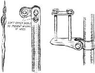
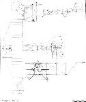
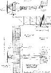
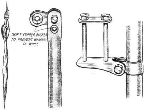
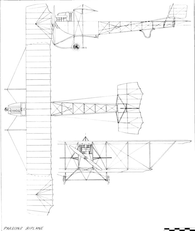
From the accompanying scale drawings it will be seen that the machine is a biplane of the tractor type with a monoplane fuselage. Although the main planes resemble in their general appearance those of the Caudron biplane, with which our readers are familiar, they differ from that well-known design in several details. For instance, the planes are not warped for maintenance of lateral stability, this function being carried out by flexing the trailing edge of the outer part of the upper plane. From the rear spar to the trailing edge the ribs in that portion of the wing consist of steel tape instead of the usual wood construction, the object being to obtain greater flexibility without the risk of breakage. Running parallel to the trailing edge, and some six inches in front of it, is another steel tape, to which are secured the wires by means of which the trailing edge is flexed. These wires are attached at their other end to a tubular lever pivoted on the rear spar and operated through stranded cables from the controls. In order to obtain greater efficiency the cord of the flexing portion of the wing is made slightly wider than that of the rest of the wing. The main planes are built in three sections for ease of dismantling, and the fabric is laced together at the joints. In order to minimise stresses on the fabric the cords are passed through an aluminium strip, instead of through eyelets in the fabric as is usually done, and the result is an extremely neat joint.
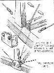
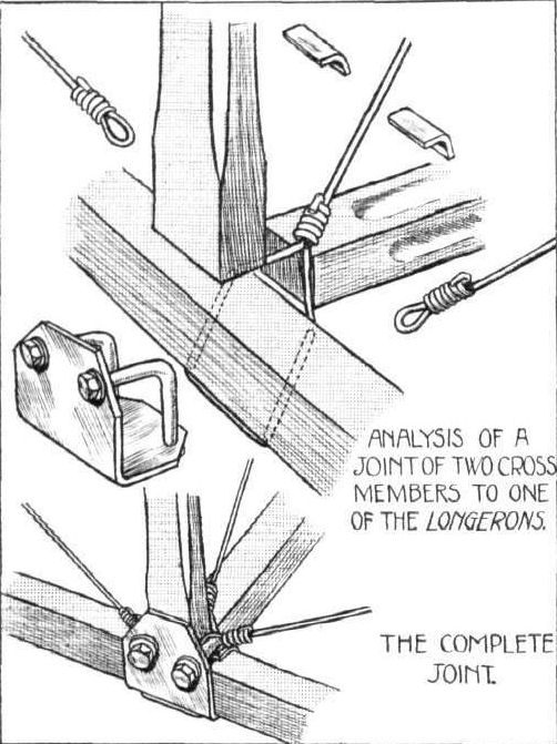
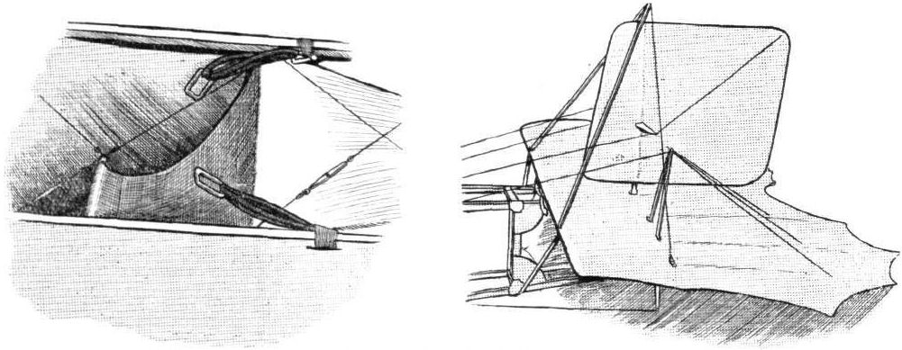
The fuselage, which is of rectangular section, is built up in the usual way, with ash longerons connected by struts and cross members of spruce, the whole being made rigid by diagonal cross-wiring. One of our sketches shows the very neat and inexpensive steel clip which forms the anchorage for these wires, and it will be seen that, with the exception of two small holes just large enough to accommodate one of the wires, the longerons are not pierced. With a view to obtaining greater rigidity against twisting strain, the fuselage does not taper to a knife's edge, but maintains its rectangular section to the rear end. Attached to the fuselage by four long bolts and four steel tubes is the tail plane, which is similar in construction to the main plane, the rear portion of it being flexed up and down for elevation and depression. Steering in a horizontal plane is effected by means of a rudder situated wholly on top of the tail plane, and pivoted on a steel tube approximately on its centre of pressure. One of the accompanying sketches will give a good idea of the arrangement of the tail planes.
A skid of malacca cane protects the tail from contact with the ground, whilst the chassis consists of two ash skids placed widely apart and connected to the lower main plane by six struts of English ash, the whole structure being made rigid by suitable cross-wiring. A single axle carrying two wheels is sprung from the skids by means of rubber shock-absorbers. To prevent this axle from bending in a heavy landing, wires are carried from the centre of it to the lower plane. A rubber shock-absorber is introduced in the wires in order to take up any slack due to the upward travel of the axle. Mounted on transverse tubular bearers is the engine, which, as has already been said, is a 4-cyl. Aster car engine which has been slightly lightened for flying purposes. It is cooled by two radiators placed immediately behind it inside the fuselage. It drives a Normale propeller of 8 ft. 2 in. diameter, 4 ft. 2 in. pitch, at 1,100 r.p.m.
Petrol and oil are carried in a tank in front of the pilot's seat, which consists of a piece of canvas slung from two transverse steel tubes inside the cockpit. It will be noticed that the fabric covering only extends a few feet behind the pilot's seat, terminating in a pyramidal stream lining, as it has been found that the rudder is more effective when the rear portion of the fuselage is left uncovered.
The controls are of the usual type, and consist of a central lever, which is moved from side to side for lateral balance and forwards and backwards for elevation and depression. A foot bar operates the rudder.
Flown by Mr. Jack Alcock, the machine has shown itself capable of very good work, and its performances to date include that of climbing to an altitude of 2,000 ft. At the present moment the Parsons pendulum paddlewheel stabilizer is being fitted, and tests of this interesting device will be carried out in the near future.
Показать полностью