Описание
Страна: Франция
Год: 1914
Варианты
- Breguet - 3 - 1910 - Франция
- Breguet - G.4 / AG.4 - 1914 - Франция
- J.Davilla, A.Soltan French Aircraft of the First World War (Flying Machines)
- J.Davilla Italian Aviation in the First World War. Vol.2: Aircraft A-H (A Centennial Perspective on Great War Airplanes 74)
- L.Opdyke French Aeroplanes Before the Great War (Schiffer)
-
L.Opdyke - French Aeroplanes Before the Great War /Schiffer/
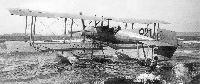
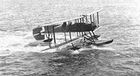
Breguet G-4, No 147, hydro. There, is clearly no relation between the G-3 (in text) and the G-4, except for the engine.
-
J.Davilla - Italian Aviation in the First World War. Vol.2: Aircraft A-H /Centennial Perspective/ (74)
Breguet HU 3 floatplane in Italian naval service. (Roberto Gentilli)
-

J.Davilla, A.Soltan - French Aircraft of the First World War /Flying Machines/
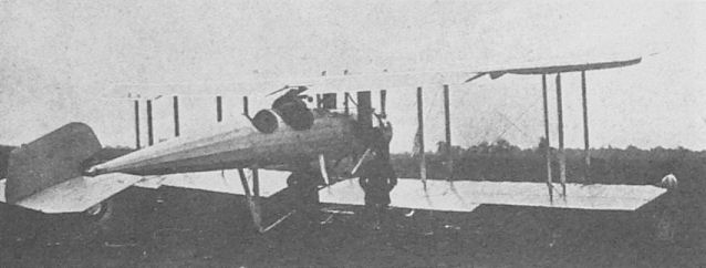
Breguet type 1914 (U2) with 130-hp Gnome piloted by Paul Derome.
-

Jane's All The World Aircraft 1919 /Jane's/
Military 2-seater. 1914 type with rigid wings and ailerons. Used for reconnaissance at start of war by French, British and Italian services. RFC nickname "Tin Whistle". 110 h.p. Salmson-Canton-Unne radial engine, offering 68 mph.
-

J.Herris - Weird Wings of WWI /Centennial Perspective/ (70)
Breguet AG 4 serial BR.53. It was based at Bourget in 1914.
The Breguet AG 4 of 1914 was a two-seat fighter; the observer had a flexible gun but there was no gun for the pilot. Despised by its crew when tried in combat, fortunately only two were built. -

J.Davilla, A.Soltan - French Aircraft of the First World War /Flying Machines/
Breguet AG 4; this airplane was fitted with a 160-hp Gnome.
-

J.Davilla, A.Soltan French Aircraft of the First World War (Flying Machines)
Breguet 13/X/AG 4
The Breguet 13 first appeared in 1913 (hence the "13" designation which was bestowed by the aviation press). It was powered by a 100-hp Gnome 9J and had a tractor layout. It was tested at Reims in September 1913 but was not adopted for military service. A second version, powered by a 160-hp Gnome engine, was named the Type "X" by Breguet. The press thought the X was a roman numeral so labeled it the Type 10. It was this variant that led to the AG 4.
Louis Breguet had a new design under construction in 1914: it had a 160-hp Gnome and, as mentioned above, appears to have been a development of the preceding Type X . The new plane was a two-bay tractor biplane with wings of equal span, ailerons on both the upper and lower wings, and a four-wheel undercarriage. The end of the fuselage was a steel tube on which the elevator and rudder were carried. There was a small rudder located at the end of the fuselage, and a large fin extended below the fuselage. Because of the lower fin a skid had to be placed in the middle of the fuselage to prevent damage to the fin during landing.
During the German advance on Paris, Breguet moved this machine to Villacoublay and made a voluntary reconnaissance flight during which he detected a change in the advance of the German troops as they turned to the east of Paris. This information was confirmed by aircraft of REP 15 and MF 16, and the 6th Armee attacked the German flank. This resulted in the Battle of the Marne, a major victory for the Allies. Perhaps because of this historic mission, the French officially adopted Breguet's new plane later in 1914. It was later designated the AG 4, which stood for A (tractor), G (Gnome) 4 (160-hp engine). It was given the serial BR 52. Modifications to the aircraft included fitting a much larger fin and rudder. These modifications were carried out by Rene Moineau and were intended to improve directional control. In addition to these changes, a rack to carry flechettes was mounted on the rear cockpit, and the aircraft was armed with a Hotchkiss machine gun fired by the observer (who sat in the rear cockpit). The aircraft was assigned to BR 17 in September 1914.
A second version of the new tractor was built and given serial BR 53. It, too, was armed with a Hotchkiss machine gun. BR 52 had been struck off charge before the end of 1914; BR 53 made air defense patrols from Le Bourget until it crashed on 26 December 1914.
The AG 4 (serial BR 52) was despised by those who flew it. A letter dated 25 October 1914 from the commander of BR 17 (Capitaine Benoist) stated that the BR 52 was unusable. He cited the fact that the engine had to have five cylinders replaced alter only three hours flying time. Bares responded on 20 October 1914 by reassuring the pilots of BR 17 that assigning the type to the unit was an "unfair experiment" and promised the aircraft would be replaced. A letter to Bares from Louis Breguet stated that he believed that the AG 4 project could be salvaged if it were fitted with a new 200-hp engine, and possibly by replacing the wing. It is not known if Breguet carried out these modifications, but no further AG 4s were purchased by the military.
Breguet AG 4 Two-Seat Fighter with 160-hp Gnome
Span 15.35 m: length 8.25 m; height 3.30 m
Empty weight 950 kg; loaded weight 1,350 kg.
Maximum speed: 100 km/h; climb to 500 m in 12 minutes; ceiling 1,500 m
Armament one Hotchkiss machine gun and flechettes
Two built
Описание: