Описание
Страна: США
Год: 1913
Журнал Flight
Flight, January 17, 1914.
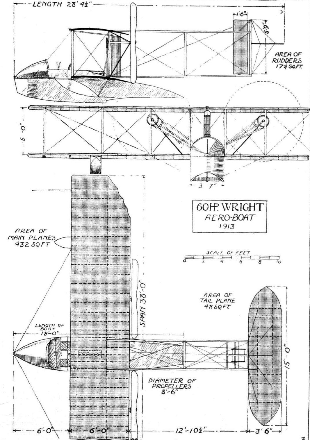
THE 60 H.P. WRIGHT AERO-BOAT.
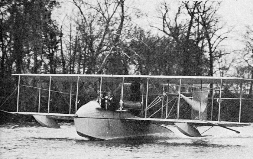
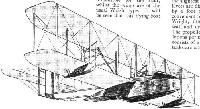
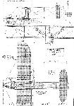
THE popularity of the "flying-boat" type of hydroaeroplane in America is emphasized by the fact that the Wright Co. has now listed a machine of this type, known as model G. An interesting point in connection with this machine is that it is the result of the collaboration of two pioneers: Orville Wright, of course, being responsible for the aeroplane, while Grover C. Loening - one of the earliest experimenters with the flying boat - has contributed his share of the design in respect to the latter. Although this new Wright model is of the flying-boat type, it really possesses one or two of the characteristics of the single-pontoon type of machine - like, for instance, the Wright hydro-biplane described in FLIGHT for September 6th last. It is, in fact, a combination of both systems, possessing, it is claimed, the advantages of each without the disadvantages of either. This will readily be appreciated by a glance at the accompanying scale drawings, for it will be seen that the boat differs from the usual type in that, instead of stern-tapering to the tail planes, it is comparatively short, like a pontoon, yet at the same time the seaworthiness of the boat system is retained and the tendency of the pontoon to dive under water is reduced to a minimum. Again, the pilot and passenger are not in such close proximity to the water as in other boats, for they sit on the deck and are thus in a somewhat safer position in case of the boat being swamped by a wave. The boat consists of an alloy metal hull, built up on a strong wooden framework. It is 18 ft. long, with a maximum depth of nearly 3 ft. and a beam amidships of 3 ft. 7 ins. The bow is pointed and the stern tapers to a horizontal knife-edge. It is fitted with a single hydroplane step and the curvature of both fore and aft surfaces has been very carefully worked out. The boat is divided up into six watertight compartments and weighs, complete with engine-bed, seats and "cabin," only 305 lbs. The outer surface of the metal hull is specially treated to resist the action of sea water, &c. Two auxiliary floats, also of metal, are mounted on the leading edge of, and below the lower planes, one on either side of the boat, midway between the latter and the wing-tips. Mounted on the deck of the boat amidships are the main planes and the engine, and just forward of the leading edge of the lower plane are the two seats for pilot and passenger, side by side, whilst right in front is a cowl forming a cockpit. The main planes, as with the rest of the aeroplane component, follow the usual design of the Wright land machines, being built up of hollow spars and spruce ribs, the front spars forming the leading edges. Extending back from the rear spars is the orthodox Wright tail outrigger carrying a flexing elevator, somewhat larger than usual, mounted in front of which are the twin rudders. It will be seen that the engine is not mounted alongside the seats as in former models, but behind them, exactly in the centre of the lower plane. The power plant consists of one of the latest 60 h.p. 6-cyl. Wright motors (water-cooled), 4 3/8 ins. by 4 1/2 ins. bore and stroke, which drives a pair of propellers by chains in the conventional style. The propellers are placed a little higher in order to clear the water, and a corresponding alteration has been made to the elevator so that it comes level with the line of thrust. A foot throttle as well as a hand lever on the instrument board is provided for controlling the engine. The engine may be started by means of a hand crank situated just behind the seats, or a self-starter can be fitted if desired, whilst provision has been made for the fitting of a silencer. The machine is controlled in the air from either seat by the usual Wright system of levers, whilst the steering of the machine when hydroplaning is facilitated by two paddles mounted on the lower wing tips and operated from the cockpit. No front "blinkers" are employed, and instead of using a piece of string to indicate the machine's attitude, a small flag is carried by a mast in the bow, which, besides serving its useful purpose, adds to the appearance of the aero-boat. The total weight of the machine empty is 1,200 lbs., and the useful load is about 600 lbs. During the past few months Orville Wright has been carrying out some exhaustive tests with one of these aero-boats with entirely satisfactory results, a speed varying from 38 to 60 m.p.h. being obtained with two up. It rises from the water after a run of not more than 200 ft., and it is very stable in high winds.
Flight, March 7, 1914.
SOME AMERICAN FLYING BOATS.
Wright Flying Boat.
The Wright flying boat is the result of the collaboration of the Wright Company and Mr. Grover C. Loening, Mr. Loening being responsible for the boat, whilst the wings are of the usual Wright type. It will be seen that this flying boat differs considerably from those previously described, the main characteristics of this machine being the comparatively short boat, which does not carry the tail planes. These are carried on tail booms in a similar way to that employed in the usual Wright machine.
Perhaps the most interesting part of this machine is the boat hull itself, which is of novel design and construction. The hull is V-bowed, and the hydroplaning bottom consists virtually of two hydroplane surfaces, both presenting their most efficient angle to the water, while at the same time allowing for the best lifting angle of the planes, and the best thrust line combination. The rear plane has been studied with great care, since the angle of this plane for its highest efficiency requires consideration of the wave action induced by the front hydroplaning surface. The hull is of alloy metal, precaution being taken to make it impervious to the action of salt water by a special surface treatment. The hull, which is 3 ft. deep, 18 ft. long and 43 in. wide, weighs, fully equipped with engine bed, seats, dashboard and hood, 305 lbs. The hull is divided by bulkheads into six watertight compartments, and, since the motor and seats are set above the top of the watertight portion, the hull itself is really a sealed pontoon.
The seats are arranged side by side in front of the lower wings, inside a very neat cockpit, the arrangement of which is reminiscent of motor car practice. On a very neat dash in front of the seats is a complete set of instruments. Entrance to the cockpit is by side doors, and the upswept deck in front of the occupants' seats forms a very effective shield for the protection against wind and water spray. Instead of the usual "string" fitted on all Wright machines, a small flag is fitted at the bow, which serves to indicate the slightest tendency of the machine to side-slip. Double control levers are disposed in front of the seats, and the engine is controlled by a foot throttle combined with a hand lever throttle placed convenient to either operator. The engine, a 6-cylinder 60 h.p. Wright, fitted with an electric self-starter, is set low behind the seals and drives two propellers in the customary Wright fashion. The propellers are 8 ft. 6 ins. in diameter, and revolve at 600 revolutions per minute, at full throttle. The hand starting mechanism consists of a safety starter geared up from the engine. The fuel tanks are situated in a separate compartment in front of the engine. The aeroplane part of this machine follows standard Wright lines, the wings being built up in the usual way, of ribs with spruce flanges, and web blocks over hollow spars. As usual, the front spar forms the entering edge of the main plane. The usual Wright control is fitted, wing warping being employed for the maintenance of lateral stability. The elevator, which is of the usual Wright flexing type, has been raised approximately to the thrust line, and has an area of 48 sq. ft. The vertical rudders and elevator are carried by the conventional Wright tail-outriggers, which are tapered and hollowed out for lightness.
In addition to the main float or boat, two auxiliary floats are fitted. These are also of an alloy metal, and weigh 11 lbs, each. In order to facilitate manoeuvring while on the water, a curious paddle control system has been applied. The paddles are hinged to the front spars near the lower wing tip, and are operated by a separate system of wires running from the cockpit. When it is desired to turn to the left, the left-hand paddle is lowered and, causing a drag on the left side, turns the boat in that direction, whilst the opposite procedure is followed for making a right-hand turn. The characteristics of the Wright flying boat, of which scale drawings appeared in our issue of January 17th, are :-
Span of boat planes 38ft.
Length overall 28 ft. 4 1/2 in.
Chord 6 ft.
Gap 5 ft .
Total lifting surface 432 sq. ft.
Total weight 1,200 lbs.
Speed . 38to 60 m.p.h.
Flight, August 7, 1914.
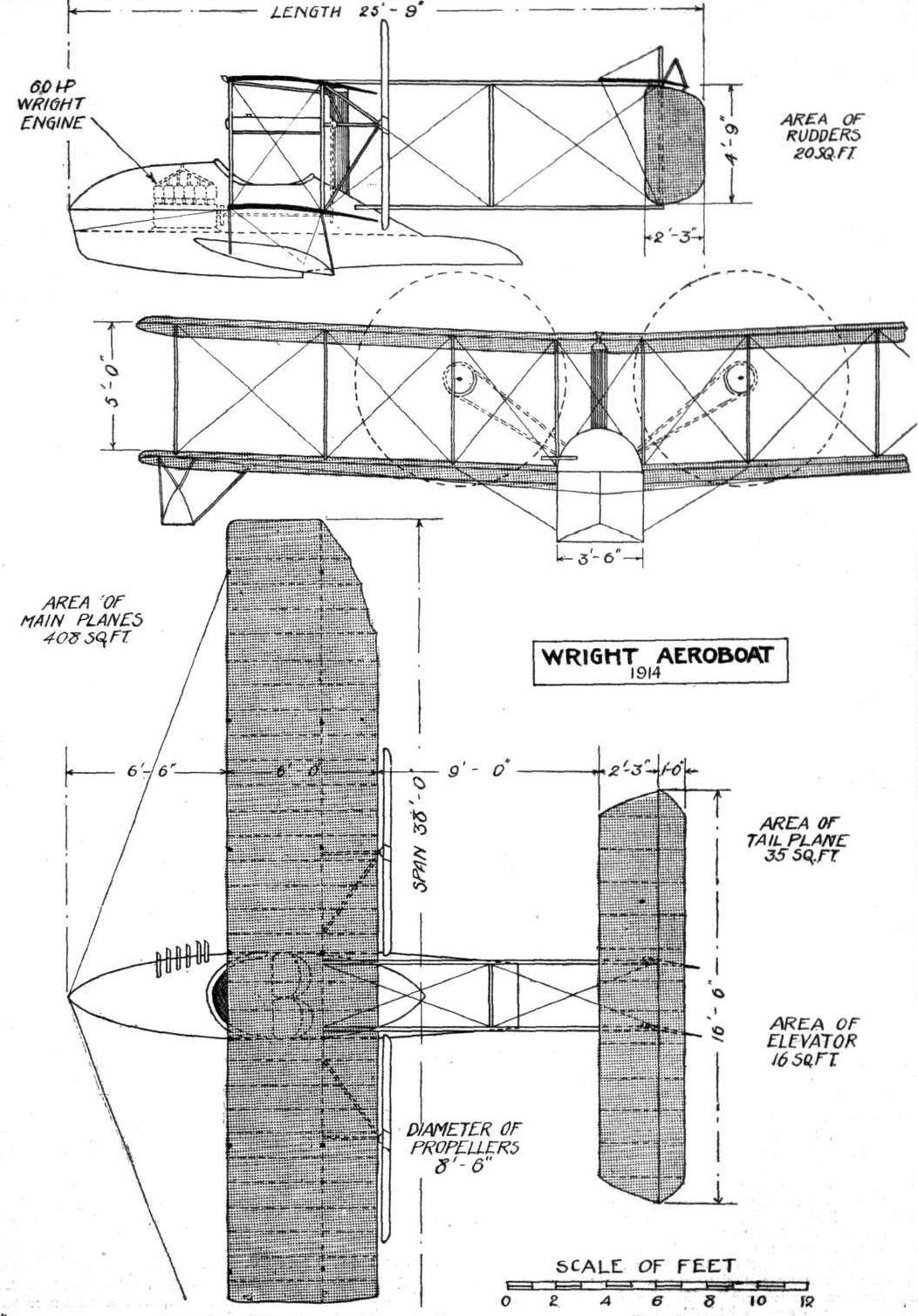
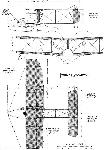
THE LATEST WRIGHT FLYING BOAT,
THE subject of our scale drawings this week is a development of the Wright flying boat which was illustrated and described in our issue of January 17th last. A comparison of the scale drawings and other illustrations of the two machines will reveal that two main alterations have been effected in this latest product of the Wright Company. In the earlier model the engine was placed behind the pilot's and passenger's seats, whilst in the new machine it is mounted in the nose of the boat. Another innovation is to be found in the arrangement of the tail planes, which now follows more or less standard lines.
An interesting point in connection with the construction of the boat, and one which is not apparent from the illustrations, is the fact that this structure consists of two parts. The lower portion of the boat forming the hydroplane surfaces and step is virtually a sealed pontoon, the deck of which is shown by the dotted line in the side elevation of the scale drawings. The second part of the hull is formed by extending the sides of the pontoon upwards to form an enclosed body for the engine and occupants, protecting them very effectively from water spray. Constructionally, the boat is built up of an exceedingly strong framework of ash and spruce, covered with a thick metal sheeting, which has been carefully treated both inside and out to protect it against the deteriorating action of sea water. The streamline hood over the engine and around the seats has been made stronger than usual, and is now built up of a combination of metal and double planking of wood covered with fabric. Air is admitted to the step of the float by means of tubes running from the deck in the vicinity of the seats, through the watertight pontoon, and out at the step. These tubes serve not only to ventilate the step but drain the cockpit, in which the seats are located, of any water shipped in bad weather, in a similar manner to that employed in self-bailing lifeboats. With this provision there is no danger of flooding the cockpit, as the water will immediately flow off either through the tubes or out to the rear along the water-tight deck.
The engine - a six-cylinder 60 h.p. Wright - is mounted on top of the watertight deck and in front of the seats. Transmission is by means of a central shaft passing under the seats and thence by chains to the two propellers, which are, as usual, situated behind the main planes. As customary in Wright practice, one of the driving chains is crossed in order to make the propellers revolve in opposite directions. As in the land machines, the propellers are geared down and rotate at approximately 580 r.p.m., but in the reverse directions customary in previous Wright models.
A refinement not usually found on aeroplanes has been introduced in the transmission system by incorporating shock absorbers in the coupling between the engine and the driving shaft.
The metal covering over the engine is made in the form of two large sliding hatches, which, when removed, give access to the engine, and when closed serve as a practically watertight covering. As we have already mentioned, this covering has been considerably strengthened in the new machine, so that it is possible for the boat to plunge head on into a large wave without any danger of having the water flood the "engine room" with detrimental effect to the running of the engine, whilst the large removable hatches allow minor adjustments being made with the engine running.
As will be seen from the accompanying scale drawings, the main planes are of the same plan form as previous models, but differ considerably from previous Wright practice in that they are set at a slight dihedral angle, and have a section of much greater thickness than has been previously employed. The ribs are now made of solid I-section, and the depth of the spars has been considerably increased, resulting in a much stronger wing construction. The very highest grade of steel wire is used throughout, and wire strainers and other joints, apt to become loosened, have been almost entirely eliminated, and all the important lift wires, as well as the control cables, are in duplicate.
Under the tips of the lower wing are mounted auxiliary floats, attached to the wing spars by strong steel braces. In the previous model, it will be remembered, paddles were fitted to the wing tips for the purpose of steering the machine on the water, but as these were found to be unnecessary they have not been used in the new machine, which answers the rudders well when taxying.
One of the features which have characterised Wright machines has disappeared, i.e., the flexing tail plane. In its stead is fitted a fixed tail plane bolted to the upper tail booms, to the trailing edge of which is hinged the elevating plane. Below the tail planes, and pivoted around two steel tubes, forming at the same time the rear struts of the tail outrigger, are the twin rudders, which also differ in shape from those of earlier Wright machines.
Dual control is fitted, and provision has been made for mounting either standard Wright controls or the new Wright wheel control.
The weight of the machine empty is 1,300 lbs., and the speed variation ranges from 40 to 60 m.p.h.
- Журнал Flight
Фотографии
-

G.Loening - Takeoff into Greatness /Putnam/
Orville Wright tests the Model G flying boat on the narrow Miami River.
-
Журнал - Flight за 1914 г.
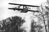
A view of the Wright aero-boat in flight.
-
Журнал - Flight за 1914 г.
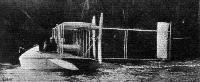
The new Wright aero-boat, as seen from the side.
-
Журнал - Flight за 1914 г.
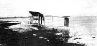
The Wright flying boat on the beach.
-

Журнал - Flight за 1914 г.
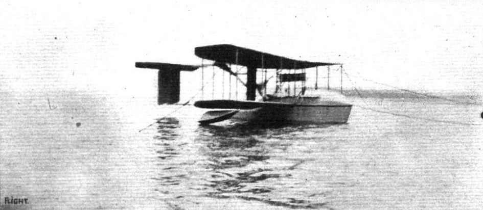
The latest Wright flying boat at its moorings.
-
Журнал - Flight за 1914 г.
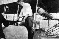
Photograph showing how admittance to the pilot's cockpit is gained through a small side door similar to those of a motor car.


-
Журнал - Flight за 1914 г.
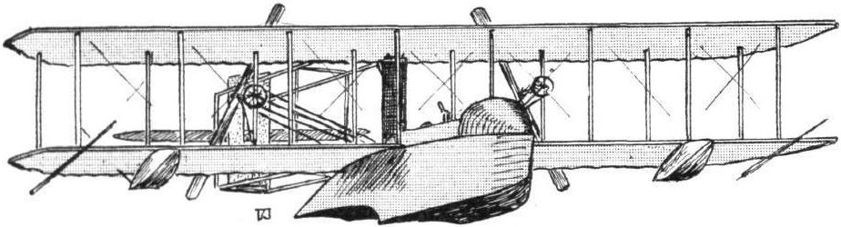
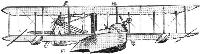
Sketch of the Wright aero-boat.
-
Журнал - Flight за 1914 г.
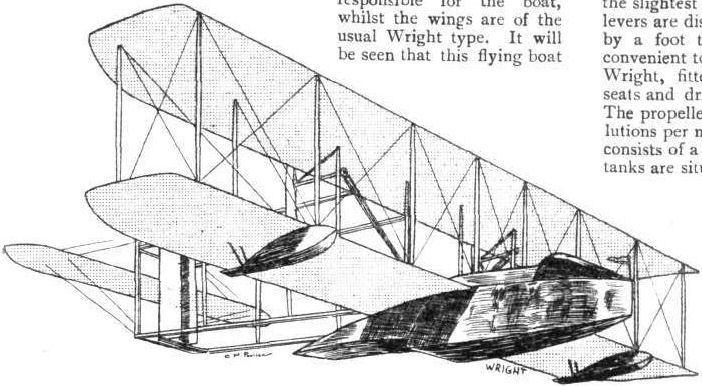
The Wright flying boat.
-
Журнал - Flight за 1914 г.
THE NEW WRIGHT AERO-BOAT. - Plan, side and front elevation to scale.
-
Журнал - Flight за 1914 г.
THE WRIGHT AEROBOAT. - Plan, front and side elevations to scale.