


Описание
Страна: Великобритания
Год: 1914
(проект)
Журнал Flight
Flight, January 24, 1914.
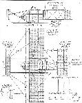
The Collins-Hancock Monoplane.
THIS machine was designed especially as a military scout.
It can be easily dissembled for road transport, the wings folding against the front skids, thus making the overall dimensions 20 ft. by 7 ft.
If necessary, the fuselage and nacelle, which are built up together, can be detached and fitted nacelle first in between the front skids, the tail plane and elevator being hung under the front elevator, thus reducing the length to approximately 15 ft.
The only controls which would need attention are the front elevator and ailerons.
The ailerons are controlled by rods and links, being absolutely rigid.
Referring to the drawing, the ailerons are hinged on to rods, B and B1, which are fixed inside the planes, so that they can revolve freely. These rods have links, A and A1, attached at their inside ends, which are connected to a rocking bar inside the nacelle, which rocks up or down according to the movement of the control lever.
When the rocking bar is working, it pushes link A up and pulls link A1 down, or vice versa, thus revolving the rods B and Bl in opposite directions, so that one aileron attains a positive and the other a negative angle of incidence.
The propeller revolves on the top member of the triangular fuselage, and is driven by bevel gears.
The twin rudders are connected together by a rod, the control wires being taken from the ends of the rod.
The pilot has a clear view below.
It is essentially a speed machine, and will land at high speeds, but the landing chassis is one which has been proved satisfactory for large and heavy machines, so should be amply strong for this machine.
#A.L.C.
Описание:
- Журнал Flight
- M.Goodall, A.Tagg British Aircraft before the Great War (Schiffer)
Фотографии
-
M.Goodall, A.Tagg - British Aircraft before the Great War /Schiffer/
Collins-Hancock monoplane. A design for a lightweight military scout.