Описание
Страна: Германия
Год: 1916
Fighter
A.Weyl Fokker: The Creative Years (Putnam)
THE BEGINNING OF THE PLATZ ERA
Reinhold Platz, the welder, was born on January 16, 1886, at Cottbus, in the province of Brandenburg, not far from Berlin. He possessed the quiet, matter-of-fact mentality of the Berliner, with a sense of reality and an awareness of his own limitations. Yet he could not have known the weight of odds against him when he assumed responsibility for the design and development of modern fighter aeroplanes at a time when the amateur designer had virtually ceased to exist and the academically trained specialist in aeronautical engineering had taken his place.
If Platz had known the scope of the design offices and experimental departments of Fokker’s competitors - such as, for instance, those of the Albatros works - and had met the experts working in them, he might well have abandoned any thought of playing David against these Goliaths. But Platz could not know, for he had spent all his time since 1913 with Fokker at Schwerin. And yet, had he known, he might not have cared much; he had the Berliner’s reaction towards things put up to make one afraid: “Bange mache, gilt nicht!”
At this time Platz had little grounding in aircraft design, although he had gained some experience in his work with Kreutzer and in the development of the Fok. D.V from the basis of Kreutzer designs. Platz was an expert craftsman and had learned to be a production engineer; he had acquired the ability economically to organize batch production under adverse conditions. But he had no training in design engineering. The elements of statics were beyond his ken. He had no knowledge of design stressing: as he has pointed out, even the basic Euler formulae for struts remained unknown to him years after he had designed the most advanced aeroplanes. Of aerodynamics his knowledge was at best elementary, even for those days: he had never heard of Eiffel’s work. Goettingen was, for him, a pleasant little town near the Harz; the investigations of the aerodynamics school there were mysteries to him until long after the war. He knew nothing about wind tunnels. Fokker believed only in free-fiight testing, not in the “nonsense” of scientists, whom he disliked and distrusted as much as qualified engineers. Text-books counted for nothing with Fokker: they did not fly.
However, Platz had two valuable qualities often conspicuously lacking in qualified engineers: vision, and a flair for design. Moreover, he paid attention to details, and had an insatiable curiosity for learning more about the problems he was dealing with and for finding the answers to these problems by experiment. Like Fokker, he firmly believed in simplifying the flying machine as much as possible. But whereas Fokker’s belief arose from technical ignorance and the fact that simple aeroplanes were more likely to pay greater profits, Platz preferred simplicity because his experience had taught him that the simplest mechanism was always the safest and often enough the most efficient.
Platz proved to be a born engineering designer, something rather different from a trained one: he was creative by instinct, not by methods taught at a college. He possessed an extraordinary “feel” for the stresses in a structure, which was born of careful observation and ample workshop experience. It was a natural asset in design stressing, which he had to develop on his own because of his engineering ignorance. He had to develop his own methods for dimensioning vital structural members in airframes. These methods were based on systematic strength experiments; though primitive, they were effective.
The methods evolved and used by Platz were not only original but - as flying experience and later investigations by expert stress analysts showed - highly reliable. At a later period, remarkable proof of the accuracy of Platz’s methods came to fight. He had beaten the stressmen without knowing any basic theory and without knowledge of the relevant mathematics. It was as if a man of exceptional eyesight and a logical mind had discovered the life of microbes, without a microscope.
When Platz took over design work at the Fokker Works, he had new ideas. Kreutzer’s Morane-cum-Halberstadt configuration had obviously come to the end of its usefulness, and Platz gathered from Fokker that something considerably better was wanted. To him, this was a challenge to develop a really simple aeroplane. All that he had seen and done before seemed far too complicated, with so many struts and bracings, requiring much rigging and adjustment. Platz was convinced that it should be possible to make more rigid components of integral construction. Experiments had shown that it could be done without undue weight.
There was one extraordinary aspect of the conditions under which Platz had to work at Schwerin; it obliged him to grope his way towards better designs single-handed. For some incomprehensible reason, Fokker never passed on to his designer any of the engineering documents or technical information that should have reached him. Platz was never allowed to see any official design guides, specifications, test reports, type-test memoranda, or any vital information of that kind that was specifically intended for designers. Fokker would never allow him to be present at any official type test, although the IdFlieg desired designers to attend the discussions on their products. Fokker did not even tell Platz the results of type tests or strength examinations. There can be no doubt that Fokker wanted to shine as the designer of the aircraft bearing his name, and was afraid that the man who did the actual work might learn too much and might himself become known.
This attitude of Fokker’s made Platz bitter when he learned later that he had been denied so much that was essential for his work. Various engineering departments of the German Flying Corps were continually issuing secret technical information for the guidance of designers of Army aircraft, making known the requirements and views of the Army Flying Corps and passing on experience. The Technische Berichte of the Flugzeugmeisterei was a valuable secret periodical. The Technische Mappe contained detailed information on German and Allied Service aircraft, with engineering details, weapon installations, undercarriage development, details of new engines, type-test records, and so on. Another series of volumes contained comprehensive instructions for stress analysis of airframes ; this was compiled by the foremost German authorities on aircraft statics, and was finally issued in the condensed form of reference sheets for easy use without recourse to advanced mathematics. All this was kept from Platz; nor was it read or digested by Fokker himself, who never liked literature, aeronautical or otherwise.
Apart from these, there was the Bau und Liefer-Vorschriften fur Heeresflugzeuge, or BLV, the German designer’s bible. Platz was unaware of its existence, and remained so throughout the war. He was amazed to come across the various editions in mint condition when he cleared out the safe of the Fokker firm’s commercial manager Burgsdorf after the war. He had designed all Fokker aircraft since 1916 without being aware of the basic requirements governing their design.
It could be argued, of course, that Burgsdorf might have thought it his patriotic duty to withhold these secret documents even from Fokker: after all, Fokker was, or had been, an alien, and the documents contained a warning of the penalties awaiting anyone who disclosed their contents to unreliable people such as aliens. Platz is convinced, however - and former engineering officers of the German Flying Corps concur - that the commercial manager withheld the documents at Fokker’s express behest.
That Fokker was allowed to get away with this till the end of the war is the fault not least of the Bauaufsicht at Schwerin and possibly of the engineering departments at Adlershof. Roland Betsch, the permanent technical officer of the Bauaufsicht, for instance, knew Platz well and knew that he designed the Fokker aircraft. He must have deduced from Platz’s various queries that Platz was completely in the dark about basic technical information and the contents of test reports on his aircraft, all of which ought to have reached him. One would have thought it Betsch’s duty, as the officer responsible for technical liaison between the IdFlieg and the firm, to report Fokker's odd practices to his superiors and to propose appropriate action for dealing with a situation that was detrimental to the war effort and must have hampered him in effectively discharging his duties. But he appears not to have done so.
The engineering specialists seem to have suspected at an early stage that Fokker’s engineering knowledge could not be extensive; it would have been logical for them to wonder who was designing his aeroplanes. One would have thought that it was their duty to track down this mysterious designer and contact him, instead of listening to Fokker’s silly replies to technical questions. Although they were, as G. Madelung assures us, much annoyed by the flippant and evasive answers that they got from Fokker, none of them demanded that the designer of the aeroplanes should be present during the type tests and sand-loading experiments.
Yet there was one occasion when the Adlershof engineers met the Fokker designer in the flesh. A few questions might have established his identity, but all that these enlightened people did was to take no notice of his presence and to misspell his name. This was late in the war, when Fokker was threatened with criminal proceedings and needed a scapegoat; he then saw fit to take Platz along. It was Platz’s only visit to Adlershof during the entire war.
Platz himself hungered for technical information: there could be no doubt about that, and Fokker must have known. Platz would have been glad to see, for instance, any specimen stressing for an aeroplane. He would also have liked to know precisely what those Army authorities wanted. The officers of the Bauaufsicht whom he approached could give him only scanty information; they do not seem to have been very interested. All he could wheedle out of Roland Betsch were the load factors that airframe structures were expected to have. Platz was also anxious to know how his designs fared during their structural testing and in the official type tests, but Fokker evaded all these matters and merely exhorted Platz to carry on and do better.
In spite of all this, the collaboration between Platz and Fokker was otherwise good. Platz had never flown, and he had a great respect for those who not only flew but assessed the qualities of aeroplanes by throwing them about in the air as Fokker did; consequently Platz approached his work with humility and an awareness of his own limitations. The more he progressed in aircraft design, the more modest he became. He never claimed to know best, never thumped the table, rarely objected or contradicted. Fokker’s suggestions were always carefully considered and put into effect even when Platz did not agree with them. It was better to let the boss come a cropper with absurd ideas than to tell him he was wrong.
Fokker liked Platz’s humility and compliant nature and exploited them; the circumstances suited him perfectly. So Platz the self-taught designer and Fokker the first-rate experimental pilot complemented each other surprisingly well.
Experimental and developmental flying demands two main qualities of the pilot: first, he must know how to handle aircraft and have well-developed senses to note his experiences and interpret them correctly; secondly, his interpretations should suggest and facilitate remedial conclusions or improvements in the engineering domain. The latter quality is a matter of patience as well as of adequate engineering knowledge; it implies trying and trying again, making modifications until the optimum handling qualities for the aircraft in question are attained.
Fokker unquestionably satisfied the first of these requirements. He was able to fly any aeroplane safely, even when its flying qualities were poor; and he had an exceptionally fine feeling for the behaviour of an aircraft. He could also interpret his sensations correctly. But until his closer cooperation with Platz he completely lacked the patience and engineering knowledge to report his findings constructively and to undertake methodical development. In many cases when he found that a new type was “bad” he simply abandoned it. This is not the way of an experimental pilot or of an aircraft designer. Most aircraft had deficiencies of one kind or another when they were first flown; they had to be developed by patient test flying and modification. This is what Fokker now came to appreciate more and more from observing the tidy and methodical way in which Platz approached the task of designing advanced aeroplanes embodying completely new features.
From this collaboration arose Fokker the superb experimental pilot. Several examples of his achievements in this sphere occur in the pages that follow; but they were many, and most of his feats in developing new types are forgotten today. A typical example was his quick conversion of a potentially dangerous aeroplane into the Fok. D.VII, making it one of the most satisfactory aeroplanes ever flown; so much so that systematic investigation and experiments conducted at a later stage and by other pilots failed to reveal the need for further modifications.
It is a matter for reflection what the consequences for aeronautics might have been if Platz had received all the technical information that the other German designers got, and had had the advantage of the advice and suggestions given verbally to technicians in the industry when they attended the Adlershof centre. Platz himself feels it would have eased his work considerably: he would have produced his new types more quickly and more efficiently. This might have been so, but it could equally well be argued that the technical isolation in which he worked drove him to original solutions that might not have occurred to him if he had had a store of technical information available to him.
It is important to note how little thought the technical departments of the IdFlieg must have given to the question of maintaining direct personal contact with the design engineers of major aircraft firms. If they had had an effective liaison it could not have happened that the man who directed the technical design and development of an important aircraft firm remained unknown to them.
The new aircraft designed by Platz was to be verspannungslos', that is to say, it had no external bracing system of struts and cables. Hence it was named the V type; and, as the first such design, its full designation was V.1. During the war and the year or so that followed the Armistice, Platz designed forty-five V aircraft. Not all of them were verspannungslos, however, and the V came to signify Versuchsflugzeug - experimental aeroplane. Not all of the forty-five designs reached the flying stage: some were abandoned during construction or at the drawing-board stage, having been superseded by more promising ideas.
A number of the V series participated in the official comparative trials (Vergleichsfliegen) at Adlershof, but only a few went into production as Service types.
All the V types designed during the war were intended for use by the Army, and most of them were single-seat fighters. None was expressly designed for the Navy or for Austria.
The V.1 biplane was completed for flight five weeks after Platz had become chief designer. This was quick work. Fokker liked quick results; Platz liked to work fast, and he and his men had worked like demons. Fokker claims to have done “everything”, but it seems that he spent less time in Schwerin than in Berlin, bewailing the A.E.G. contract and trying to get more profitable orders.
Platz had been told that previous Fokker fighters had not been fast enough. He was convinced that performance depended greatly on clean design, and that a good aeroplane should, and could, be clean as well as simple. He was also convinced of the feasibility of making cantilever wings, and Fokker favoured the idea. Platz had been told that only biplanes were wanted, so the V.1 embodied his ideas as well as any biplane could.
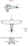
The V.1 had full-cantilever wings: it had no interplane struts. Each wing was an integral structure consisting of wooden box spars and wooden ribs, covered entirely with plywood. To obtain the necessary strength, Platz used an aerofoil section of unusual thickness: it was 20% of the chord at a time when the customary thickness was about 5% or 6%. A wing of such thickness was a revolutionary development at Schwerin. Platz was not aware, at that time, that aircraft with similar wings had already been flown elsewhere. Fokker knew, but seems not to have told him.
The box spars of the wings were unusual features. They were, of course, deep and fairly wide, to resist bending and shear loads. The top and bottom members (flanges) of each spar were laminated from several laths of pine, each 0-4 in. thick; this arrangement made it simple to vary the thickness of the flanges along the span in proportion to the local stress. The upper and lower flanges of each spar were joined by webs of plywood. These webs had the outer grain of the three-ply running normal to the spar axis.
These features were new for the Fokker firm. Previously, wing spars had always been spindled out of rectangular lengths of wood and planed down to fit the slots in the wing ribs. The skinning of the V.1 wings with plywood instead of the more conventional fabric had previously been unheard of at the Fokker works.
Little use had been made of plywood in the past. Platz introduced it to an ever-increasing extent, although he came from the metal-working side and had originally had little to do with the production of wooden wings before he came to be Kreutzer’s right-hand man in the design department. Platz found in plywood a highly suitable and adaptable material that was available in fair quantities in Germany during the war. Thin birch three-ply was at times much easier to get than good linen and dope for conventional covering. Towards the end of the war, all fabric and dopes became poor-quality ersatz, and scarce at that.
Ply-covered wings had the further advantage of requiring no internal drag bracing between the spars. Such wings had good torsional strength and rigidity, as Platz’s strength tests proved conclusively. All struts, wires, turnbuckles and fittings could be dispensed with; inside the wings, the only necessary fittings were at the wing-attachment pick-up points; in the upper wing, those for the aileron bearings and controls had to be added.
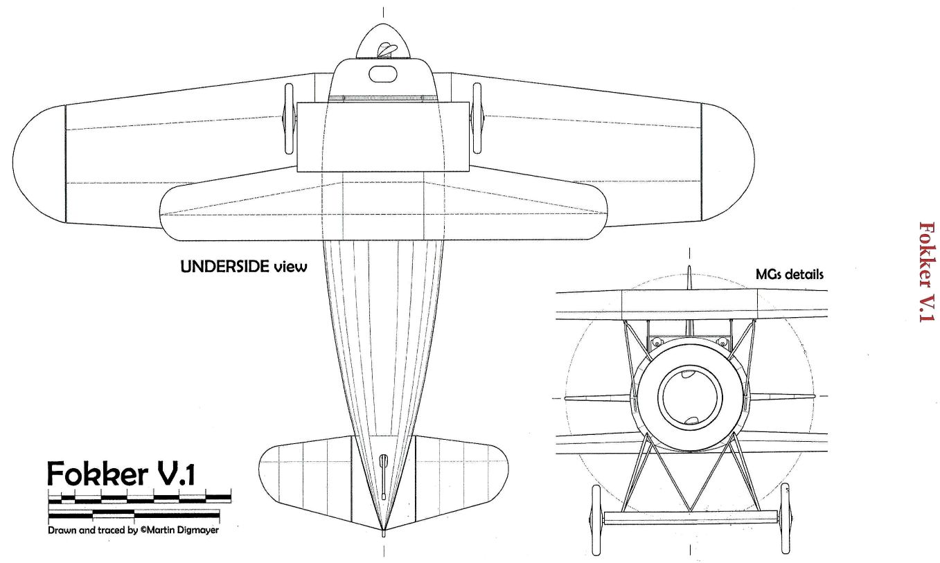
In the lower wing, the spars converged to meet at the wing tip, forming a triangular structure. There was a reason for this. Fokker had got wind of the L.V.G. D.10 project, designed by W. Rethel and P. G. Ehrhardt: this was a biplane with a retractable undercarriage in which a triangular disposition of the lower-wing spars was adopted in order to provide a convenient housing for the retracted wheels. Fokker suggested that the V.1 should also have a retractable undercarriage, consequently its wing spars were disposed in similar fashion to those of the L.V.G. D.10. The retractable undercarriage was not developed, however, and Platz dropped the complication of triangulated spars as soon as he could. In the V.1 upper wing, as in those of all subsequent Platz designs, the spars were parallel.
The design of the control surfaces was unorthodox. Instead of the conventional trailing-edge ailerons, the tip portions of the upper wing rotated. Bleriot had employed this method on his Libellule nine years earlier. In 1926, G. T. R. Hill was to demonstrate, with his Pterodactyl aircraft, that rotating wing tips provided better control at high angles of attack than conventional ailerons.
The rudder and elevators of the Fokker V.1 were similarly designed as movable extensions of the fin and tailplane. All control surfaces were aerodynamically balanced.
The unusual control surfaces seem to have proved satisfactory in flight. Fokker found no reason for changing them, though representatives of the Air Corps may have been less convinced. Service pilots in general were never enthusiastic about radical innovations, and it is still doubtful whether anyone but Fokker (and perhaps de Waal) ever tried the V.1 or the V.2. Fokker’s account is silent upon this point; Platz does not know; and no officer still living can remember seeing more than photographs of the two aircraft.
However, the new control arrangement not only led to greater simplicity in the design, but also ensured that the control surfaces were unaffected by the airflow over wing, tailplane or fin. They should therefore have been effective even at the stall.
The experimental Junkers J.7 single-seat fighter of October 1917 had lateral controls similar to those of the Fokker V.1. The suggestion may have come from Fokker.
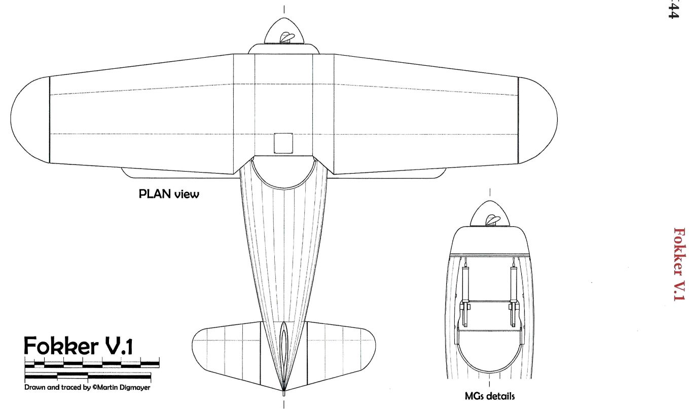
Another feature of the V.1 that was unusual for that period was the burying of all control-actuating members inside the wing or fuselage. No control horns or cables protruded into the airflow: Platz had achieved his clean aeroplane.
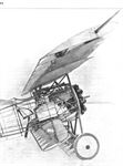
The upper wing, about 10-7 sq. m. (116 sq. ft.) in area, had slight taper without effective sweep-back. An odd problem arose for Platz, who had devised a new type of aerofoil section: what should its correct angle of incidence be? As he had no wind-tunnel facilities he lacked guidance in this problem. On Fokker’s advice, it was decided to find out by experiment with the V.1 itself. For this purpose the incidence of the upper wing was made adjustable in flight: a crank in the cockpit actuated a lever that raised or lowered the attachment of the main spar.
Fokker made the test in his accomplished manner. He found that the aircraft flew best when the angle between the flat undersurface and the direction of flight was zero. This meant that the geometric incidence of the mean camber line was 3° 50'. The subsequent V types were designed in the light of the knowledge thus gained.
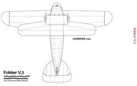
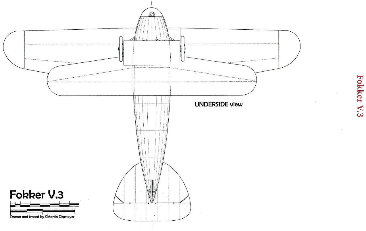
The lower wing, about 3 sq. m. (32 sq. ft.) in area, had more pronounced taper, with a swept-back leading edge and a straight trailing edge; its convergent spars have already been described. Platz disliked taper: constant-chord wings were much simpler to build. He asserted his views more firmly in the V.3 and in all subsequent biplanes and triplanes; sweep, taper and dihedral were avoided, with a few exceptions expressly demanded by Fokker. In monoplanes taper could not be avoided without incurring a heavy structure-weight penalty.
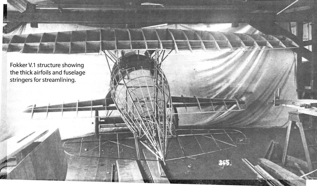
The basic fuselage structure differed little from that of earlier Fokker aeroplanes. This was understandable: Platz had contributed substantially to the development of Fokker fuselages and there was no need for a drastic change. The basic structure was faired out to a good streamline shape by means of wooden hoops and stringers, much as on the Fok. D.V; the whole was covered with fabric.
The pilot sat rather low in the fuselage. His field of vision was not particularly good: the downward view was restricted by the fairing of the fuselage and the lower wing; upwards and forwards the great thickness of the upper wing obscured a considerable area.
The engine installation and fuel system were also reminiscent of the Fok. D.V. The engine - chosen by Fokker, as the new owner of the Oberursel concern - was the 100-h.p. Oberursel. Platz cannot recall why this rather inefficient engine was chosen; he thinks it may simply be that it happened to be available. Whatever the reason, the choice was not a wise one: it prejudiced any chance of the V.1 being adopted for the Service. The engine was closely cowled and a large spinner was fitted to the airscrew. The V.1 was flown with various spinners, and with none at all, in attempts to achieve optimum performance and engine cooling.
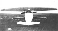
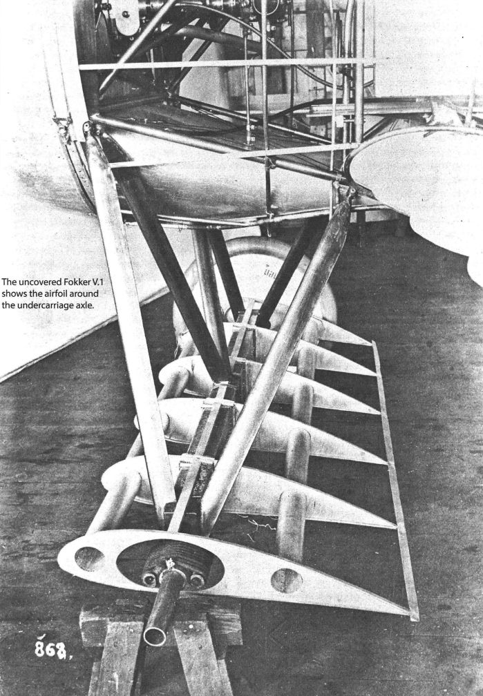
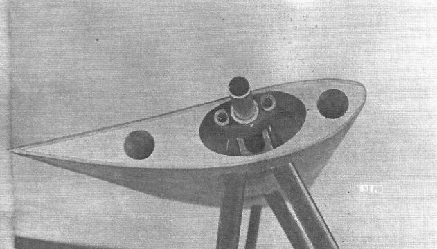
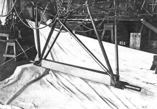
The undercarriage axle and spreader bars were faired over by a wing-like structure, which had the same aerofoil section as the mainplanes.
Air-speed indicators were not usually fitted to German aircraft at the time when the V.1 appeared. Fokker had one installed on the experimental machine; doubtless his primary object was to check the V.1's performance, but he may have felt it to be a necessity in view of the absence of the whistling of the airstream through the rigging of a wire-braced aircraft. The V.1 originally had a cup-type anemometer mounted above the lower starboard wing but this was subsequently replaced by a more suitable pressure-tube instrument. The pressure head was carried on a light pylon above the upper wing, to port and clear of the slipstream.
Tony Fokker was very pleased with the V.1. Unfortunately, however, it failed to meet the official requirements for fighter aircraft and was apparently turned down without even a type test or a structural test. There is no record of the V.1 nor its successor, the V.2, in the official files. No former member of the IdFlieg now alive can recall these two aircraft, nor can anyone remember anything about the mysterious “commission” which, according to Fokker’s book, appeared at Schwerin to admire the aircraft but turned it down flatly. Platz knows nothing more than that the first two aircraft of his design were not accepted. But neither the official records nor anyone of the IdFlieg circle can tell us anything about such a visit, and one wonders whether the official visitors of whom Fokker wrote so bitterly may not have been from the IdFlieg at all: they may have been merely officers from operational units whom Fokker wished to impress before submitting the V.1 to Adlershof. That this may be the explanation is suggested by the events during the introduction of the Fokker triplane.
Fokker implies that the V.1 was too far advanced for those whom he had asked to come and inspect it, that it was too unconventional for the military, and that the technical experts were biased against him.
These accusations sound hollow. Those levelled against the engineering specialists of the IdFlieg are particularly unreal. These men had seen many novel designs from other firms and had already shown deep, interest in the possibilities of cantilever wings and similar advanced ideas. Had they been present at Fokker’s demonstration of the V.1 they would not have rejected it out of hand merely because it was unconventional: they would have investigated it thoroughly and determined its strength by structural testing.
All this makes it the more likely that the visitors were officers from the front, and that they realized the new aeroplane would be of no use for operational purposes, and told Fokker so.
Platz was left to guess why and by whom the V.1 and V.2 were rejected. He was not inquisitive about such things, and he knew that Fokker would not tell even when pressed. For Platz it was enough to know that something better had to be created.
One is consequently left to surmise why such a progressive aircraft was rejected. Two obvious deficiencies have already been mentioned: the unfortunate choice of engine and the limited field of view. It is likely that the V.1 had proved to be rather heavy, and that its rate of climb was consequently poor. Platz had taken great care to ensure adequate structural strength; such safety in his first cantilever venture entailed additional weight. The plywood-skinned wings were heavier than fabric- covered surfaces; the formers and stringers of the fuselage added weight.
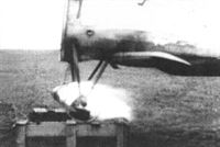
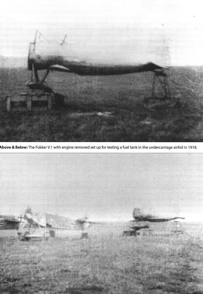
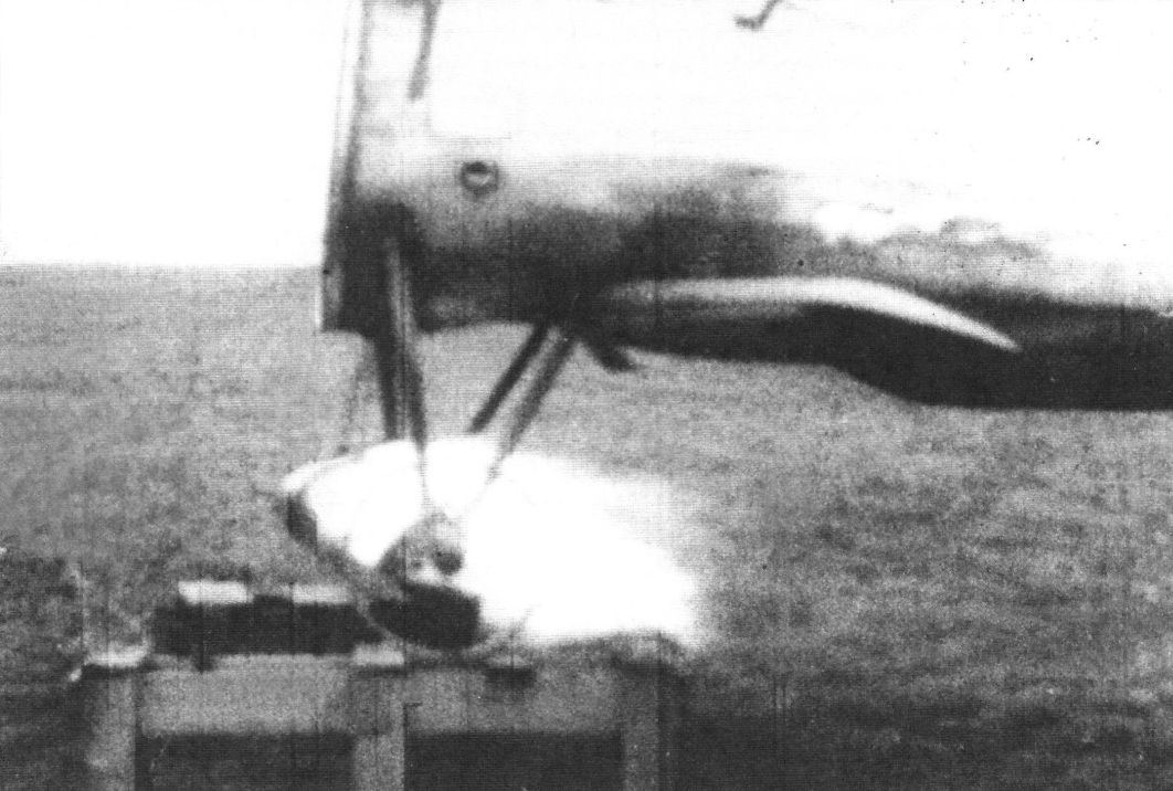
The fuselage at least survived until the summer of 1918, when Fokker used it to demonstrate the safety of his undercarriage fuel tank when leaking or set on fire in combat. Even these incendiary efforts of Fokker’s did not put an end to Platz’s revolutionary effort, however.
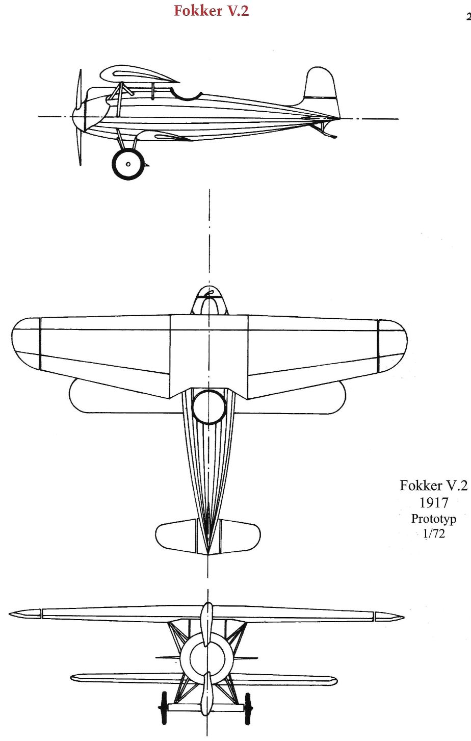
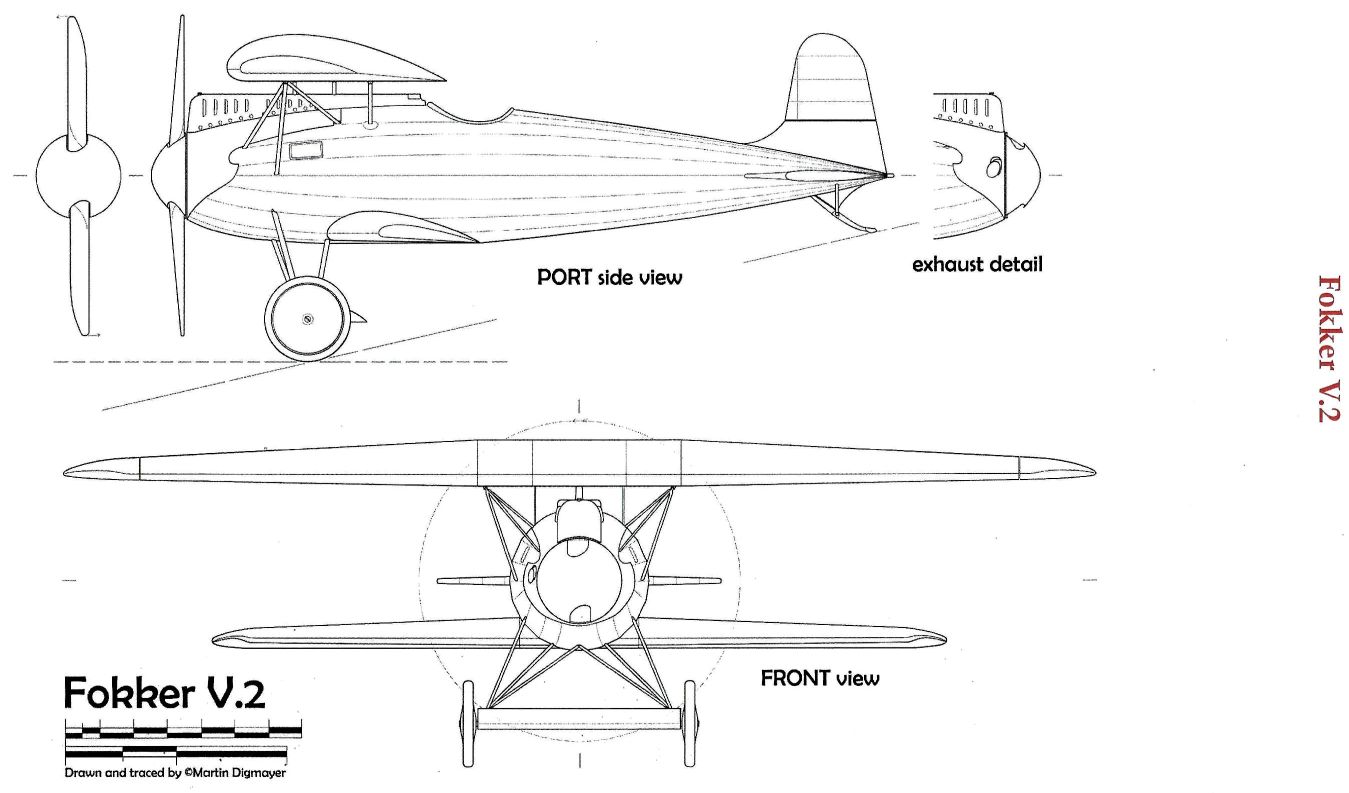
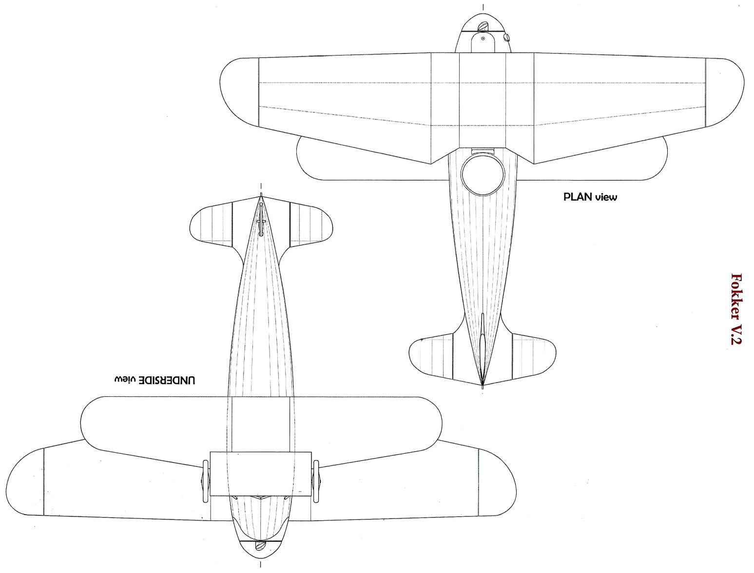
The Fokker V.2
Fokker had pursued the policy of parallel development of experimental prototypes, one with a rotary engine, the other with a water-cooled engine. This may account for the construction of the V.2, which had a 120-h.p. Mercedes engine.
It is not clear why Fokker chose an engine that was operationally obsolete. Platz believes that availability alone decided Fokker’s choice of engines for experimental aircraft. (But surely Fokker would not have hesitated to “borrow” one of the 160-h.p. Mercedes allotted for Fok. D.IVs for a period long enough to cover the testing and demonstration of the new prototype ?)
In general appearance and design features, the V.2 resembled the V.1. It was slightly larger: the total wing area was about 19 sq. m. (205 sq. ft.), or some 4 sq. m. more than that of the V.1. The additional wing area was provided because the Mercedes was heavier than the Oberursel, and Platz believed in having the same wing loading in his parallel prototypes.
The V.2 underwent more extensive modification than its predecessor. At first the upper wing was fairly close to the fuselage, and the field of view forward cannot have been good. The wing was later raised higher above the fuselage; a clumsy radiator was let into the leading edge, where it interfered with the airflow over the wing. The view from the cockpit was still poor, and on the whole the V.2 was less impressive than the V.1.
These two cantilever biplanes had one feature that was to characterize all later biplanes and parasol monoplanes designed by Platz: the structure supporting the upper wing incorporated two splayed-out tripods of steel tubing that were attached to the front spar.
In later Platz designs, maximum weight-saving and simplification were aimed at. The fairing of the fuselage was abandoned; conventional hinged control surfaces were used; wings were covered with fabric, except on monoplanes where the need for torsional stiffness required a plywood skin.
Описание:
- A.Weyl Fokker: The Creative Years (Putnam)
- J.Herris, T.Phillips Fokker Aircraft of WWI. Vol.4: V.1-V.8, F.I & Dr.I (A Centennial Perspective on Great War Airplanes 54)
- O.Thetford, P.Gray German Aircraft of the First World War (Putnam)
- W.Green, G.Swanborough The Complete Book of Fighters
Фотографии
-
J.Herris, T.Phillips - Fokker Aircraft of WWI. Vol.4: V.1-V.8, F.I & Dr.I /Centennial Perspective/ (54)
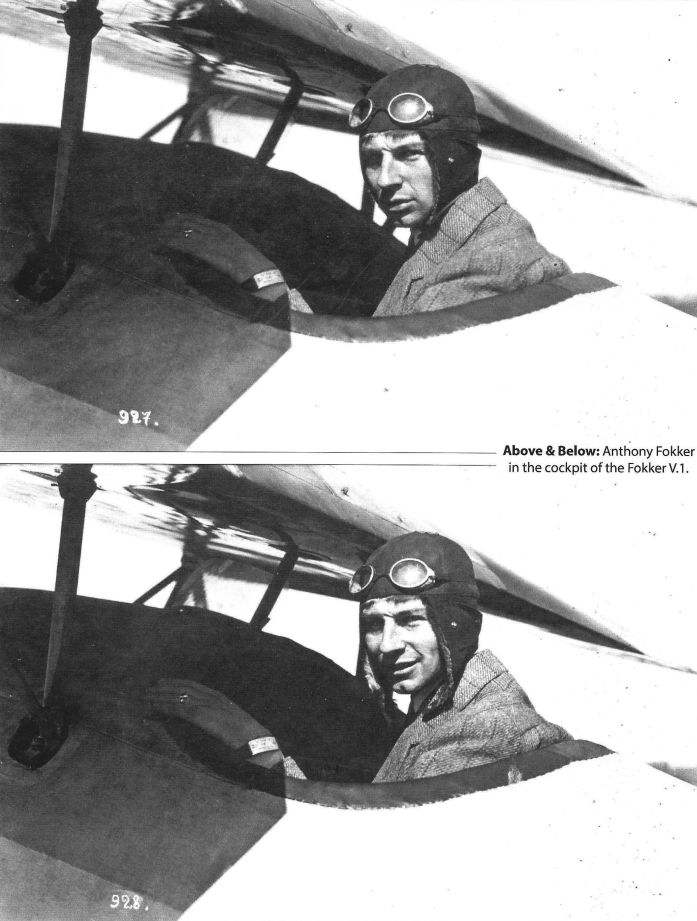
Fokker in the Fokker V.1 showing the variable angle of incidence of its lower wing.
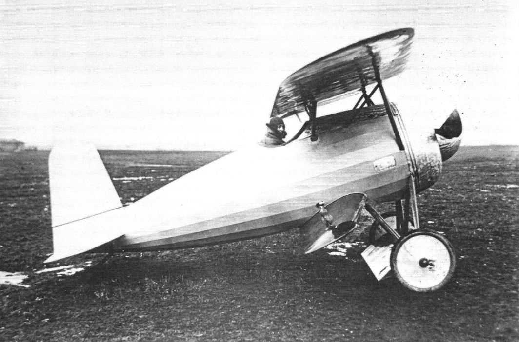
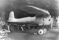
The V 1 was a radical cantilever sesquiplane, designed by Reinhold Platz, which began its flight test programme in December 1916. -
J.Herris, T.Phillips - Fokker Aircraft of WWI. Vol.4: V.1-V.8, F.I & Dr.I /Centennial Perspective/ (54)
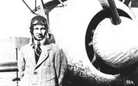
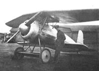
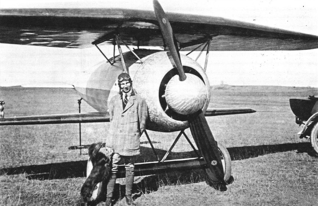
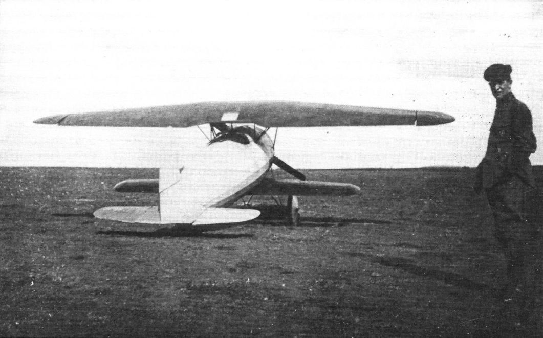
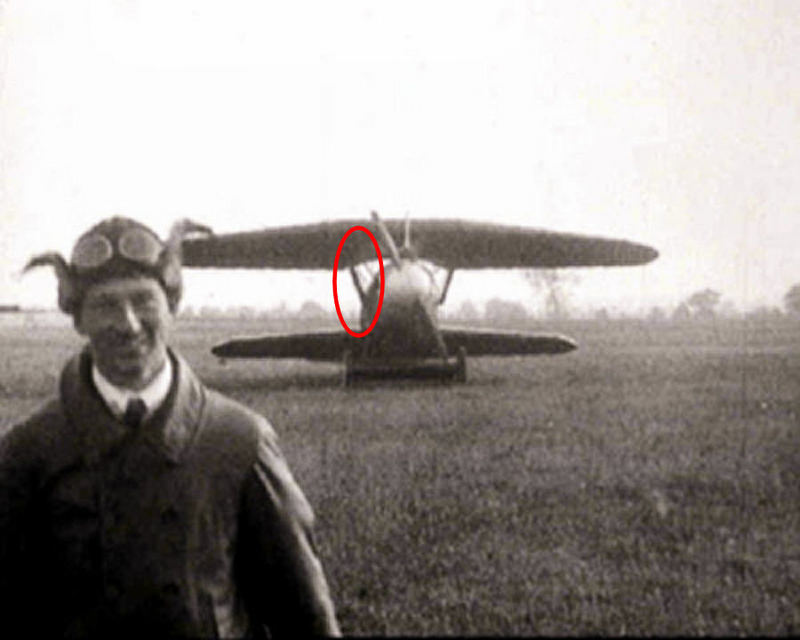
Anthony Fokker stands in front of the first version of the Fokker V.1.
-
J.Herris, T.Phillips - Fokker Aircraft of WWI. Vol.4: V.1-V.8, F.I & Dr.I /Centennial Perspective/ (54)
Closeup photo of Anthony Fokker in front of the first version of the Fokker V.1.
-
J.Herris, T.Phillips - Fokker Aircraft of WWI. Vol.4: V.1-V.8, F.I & Dr.I /Centennial Perspective/ (54)
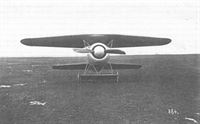
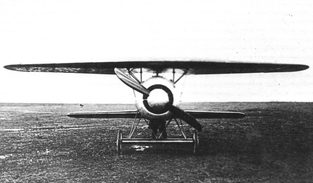
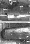
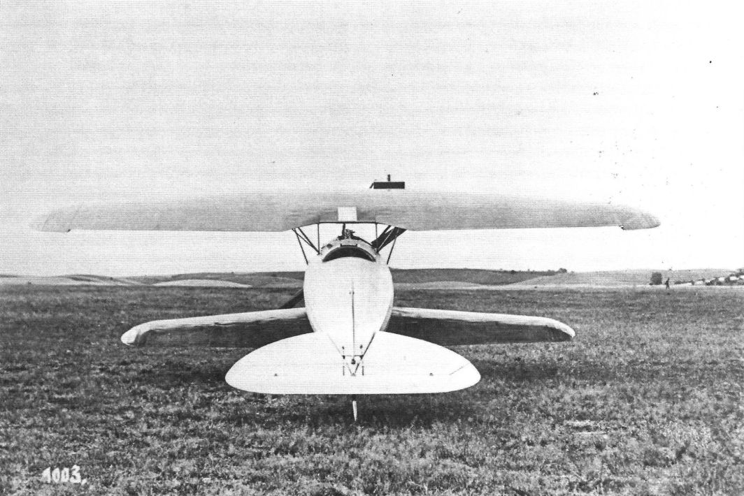
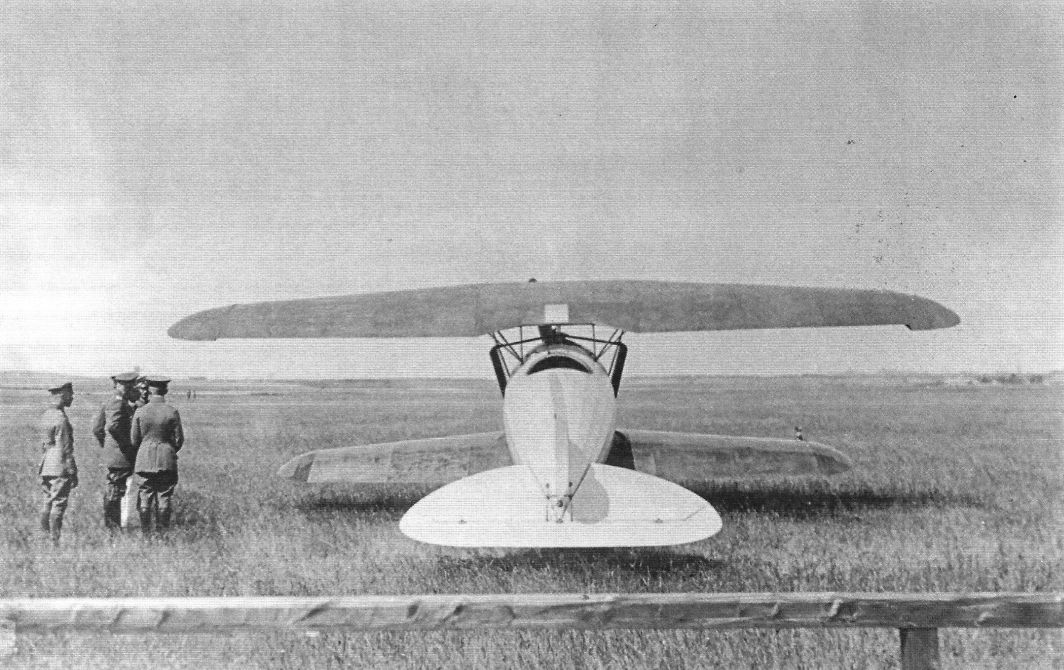
Front view of the Fokker V.1 shows the airfoil around the undercarriage axle.
-
J.Herris, T.Phillips - Fokker Aircraft of WWI. Vol.4: V.1-V.8, F.I & Dr.I /Centennial Perspective/ (54)
Front view of the Fokker V.1 shows its streamlining.
-

J.Herris, T.Phillips - Fokker Aircraft of WWI. Vol.4: V.1-V.8, F.I & Dr.I /Centennial Perspective/ (54)
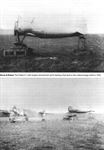
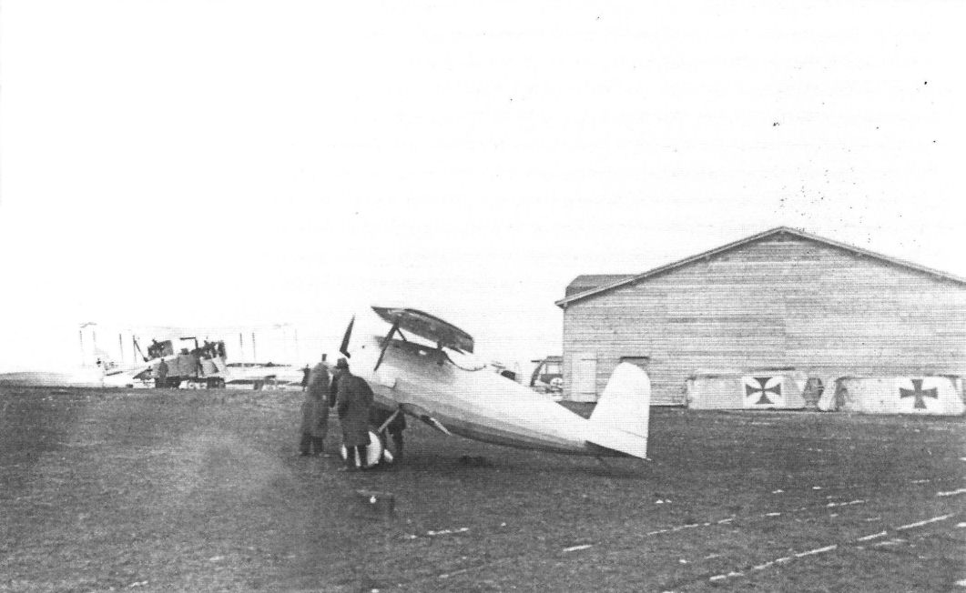
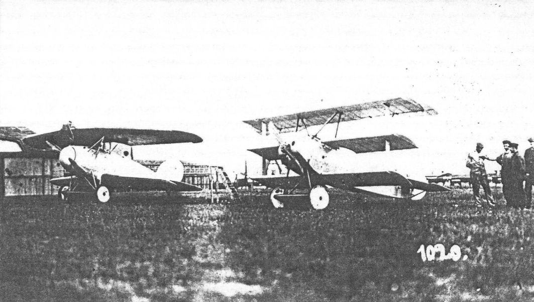
The Fokker V.1 on the Fokker airfield; the Rumpler G.I 15/15, the first Rumpler G.I bomber is in the background.
Другие самолёты на фотографии: Rumpler G.I/G.II/G.III - Германия - 1915
-
J.Herris, T.Phillips - Fokker Aircraft of WWI. Vol.4: V.1-V.8, F.I & Dr.I /Centennial Perspective/ (54)
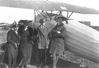
Anthony Fokker and guests stand in front of the first version of the Fokker V.1.
-
J.Herris, T.Phillips - Fokker Aircraft of WWI. Vol.4: V.1-V.8, F.I & Dr.I /Centennial Perspective/ (54)
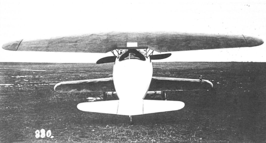
Rear view of the Fokker V.1 emphasizes the streamlined fuselage and small lower wings
-

J.Herris, T.Phillips - Fokker Aircraft of WWI. Vol.4: V.1-V.8, F.I & Dr.I /Centennial Perspective/ (54)
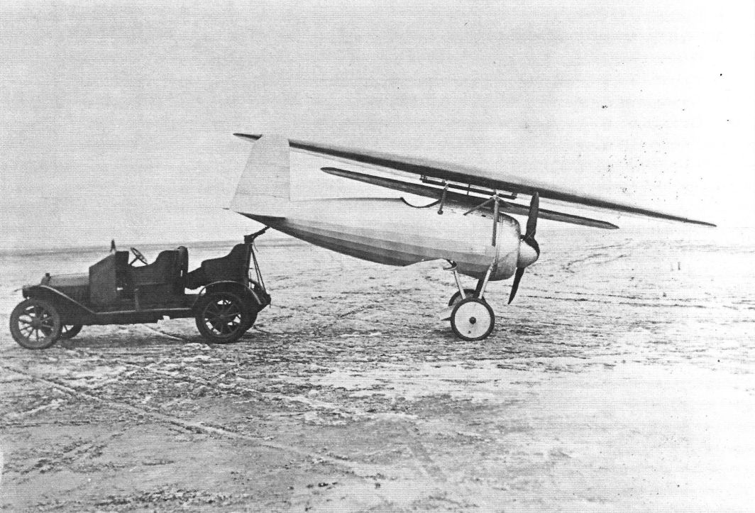
The Fokker V.1 disassembled for towing showing its one-piece lower wing.
-

J.Herris, T.Phillips - Fokker Aircraft of WWI. Vol.4: V.1-V.8, F.I & Dr.I /Centennial Perspective/ (54)
Antony Fokker in the cockpit of the Fokker V.1.
-
J.Herris, T.Phillips - Fokker Aircraft of WWI. Vol.4: V.1-V.8, F.I & Dr.I /Centennial Perspective/ (54)
Fokker V.1 second version with revised rudder.
-

J.Herris, T.Phillips - Fokker Aircraft of WWI. Vol.4: V.1-V.8, F.I & Dr.I /Centennial Perspective/ (54)
The Fokker V.1 on the airfield.
-

J.Herris, T.Phillips - Fokker Aircraft of WWI. Vol.4: V.1-V.8, F.I & Dr.I /Centennial Perspective/ (54)
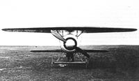
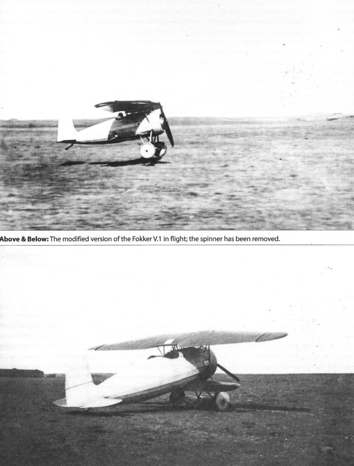
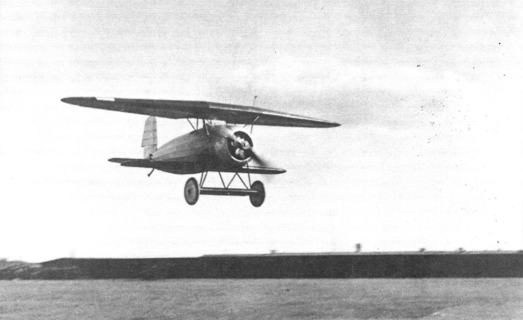
The modified version of the Fokker V.1 in flight; the spinner has been removed.
-

J.Herris, T.Phillips - Fokker Aircraft of WWI. Vol.4: V.1-V.8, F.I & Dr.I /Centennial Perspective/ (54)
The modified version of the Fokker V.1 in flight; the spinner has been removed.
-
J.Herris, T.Phillips - Fokker Aircraft of WWI. Vol.4: V.1-V.8, F.I & Dr.I /Centennial Perspective/ (54)
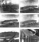
The Fokker V.1 with engine removed set up for testing a fuel tank in the undercarriage airfoil in 1918.
Другие самолёты на фотографии: Fokker D.VII / V11 / V18 / V22 / V24 - Германия - 1917
-
J.Herris, T.Phillips - Fokker Aircraft of WWI. Vol.4: V.1-V.8, F.I & Dr.I /Centennial Perspective/ (54)
The Fokker V.1 (without engine) and its airfoil fuel tank alight in the propeller blast of the D.VII without wings.
-
J.Herris, T.Phillips - Fokker Aircraft of WWI. Vol.4: V.1-V.8, F.I & Dr.I /Centennial Perspective/ (54)
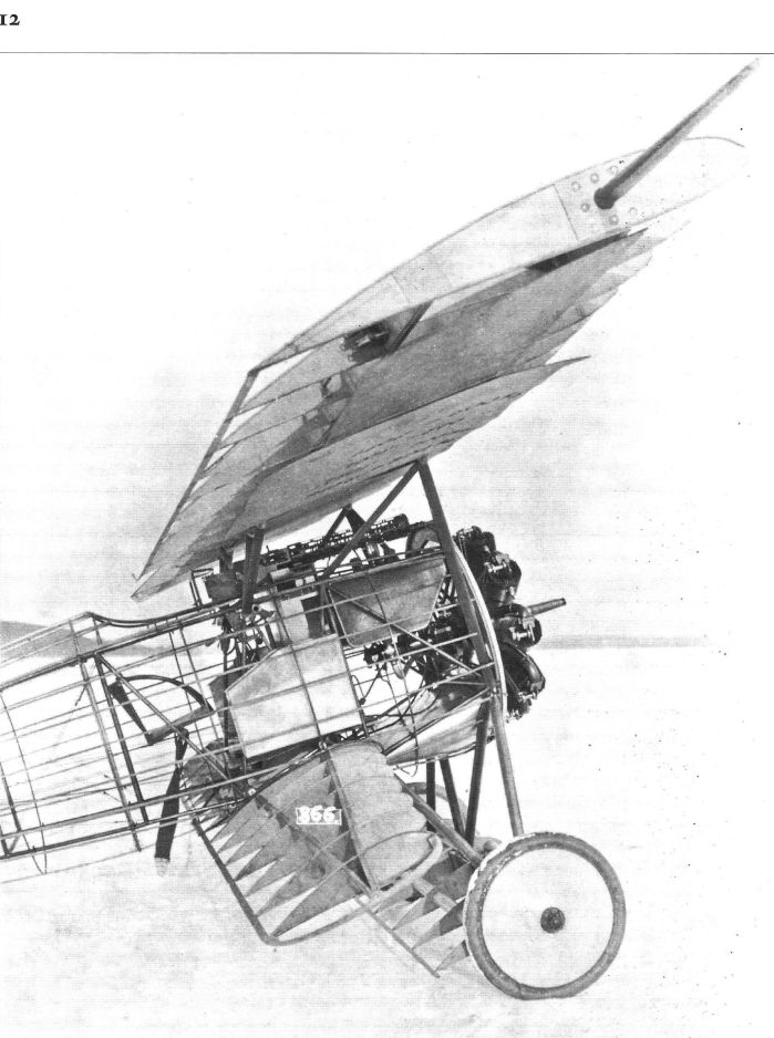
The Fokker V.1 without covering shows its simple structure, including the thick wings. Twin guns are installed.
The Fokker V1 was the first Fokker prototype with a cantilever wing. It had Fokker's welded steel tube fuselage and the first generation thick airfoil cantilever wings covered with plywood. Unusual rotating wingtips were used for roll control; these were replaced by conventional ailerons in subsequent Fokker designs. -
J.Herris, T.Phillips - Fokker Aircraft of WWI. Vol.4: V.1-V.8, F.I & Dr.I /Centennial Perspective/ (54)
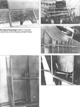
Uncovered Fokker V.1 structure showing the thick airfoils and twin machine guns.
-
J.Herris, T.Phillips - Fokker Aircraft of WWI. Vol.4: V.1-V.8, F.I & Dr.I /Centennial Perspective/ (54)
The uncovered Fokker V.1 shows the airfoil around the undercarriage axle.
-

J.Herris, T.Phillips - Fokker Aircraft of WWI. Vol.4: V.1-V.8, F.I & Dr.I /Centennial Perspective/ (54)
The Fokker V.1. Two LMG.08/15 machine-guns were fitted at this stage, but were later removed.
Fokker V.1 structure showing the thick airfoils and fuselage stringers for streamlining. -

J.Herris, T.Phillips - Fokker Aircraft of WWI. Vol.4: V.1-V.8, F.I & Dr.I /Centennial Perspective/ (54)
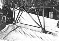
Detail of the Fokker V 1 landing gear showing the airfoil.
-
J.Herris, T.Phillips - Fokker Aircraft of WWI. Vol.4: V.1-V.8, F.I & Dr.I /Centennial Perspective/ (54)
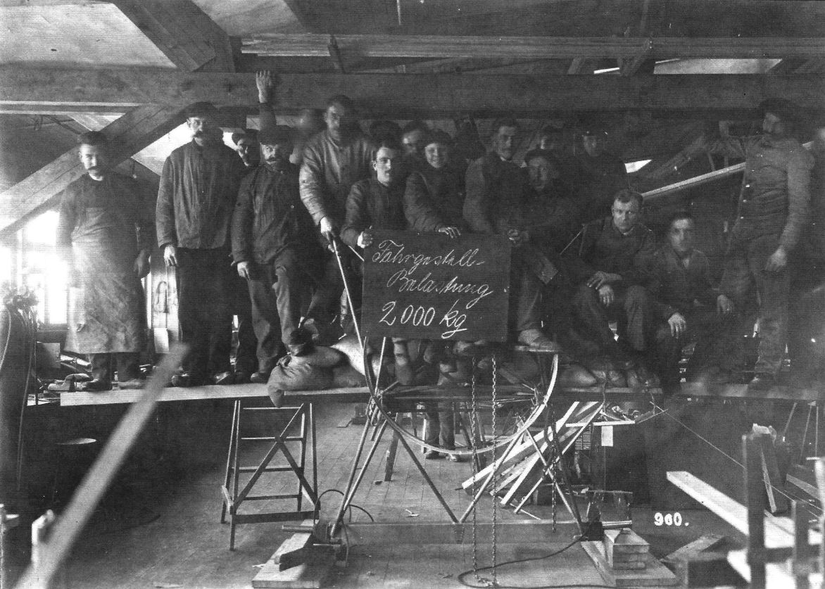
Fokker factory load testing of the Fokker V 1 landing gear.
-

J.Herris, T.Phillips - Fokker Aircraft of WWI. Vol.4: V.1-V.8, F.I & Dr.I /Centennial Perspective/ (54)
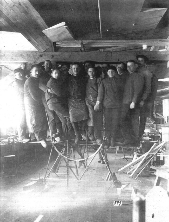
Fokker factory photo #899 shows load testing of the Fokker V 1 landing gear.
-

J.Herris, T.Phillips - Fokker Aircraft of WWI. Vol.4: V.1-V.8, F.I & Dr.I /Centennial Perspective/ (54)
Fokker factory photo #900 shows load testing of the Fokker V 1 landing gear. No doubt Fokker was keen to document the strength of his latest design after the failures of the D.I-D.IV quartet. In addition to the usual human load, numerous sandbags come into use as well. As a consequence, the total load of two tons was written onto the chalk board.
-
J.Herris, T.Phillips - Fokker Aircraft of WWI. Vol.4: V.1-V.8, F.I & Dr.I /Centennial Perspective/ (54)
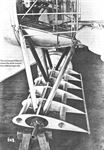
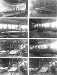
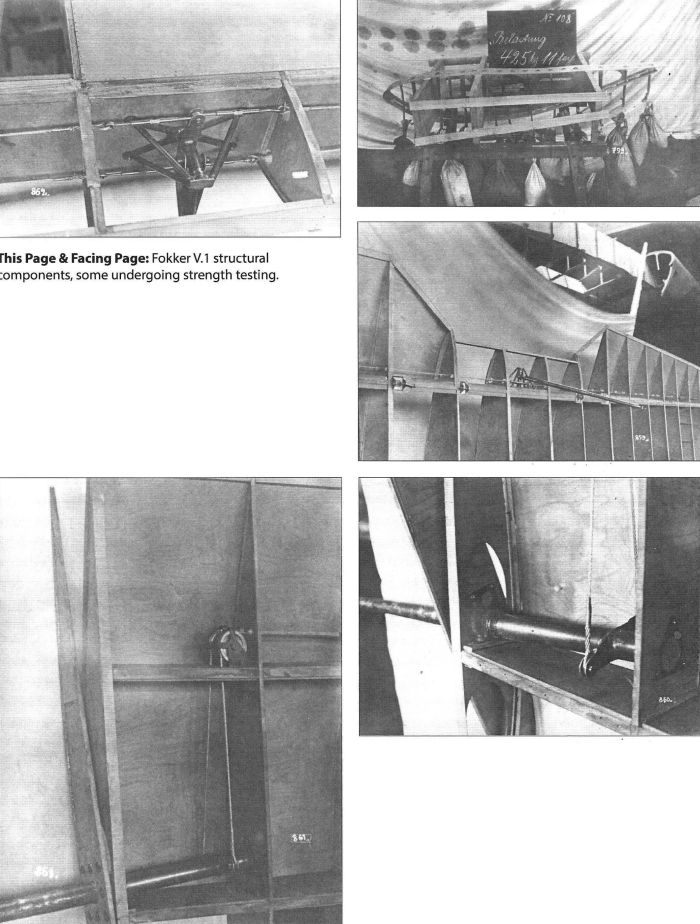
Fokker V.1 structural components, some undergoing strength testing.
-
J.Herris, T.Phillips - Fokker Aircraft of WWI. Vol.4: V.1-V.8, F.I & Dr.I /Centennial Perspective/ (54)
Fokker V.1 structure, some components undergoing strength testing.
-
J.Herris, T.Phillips - Fokker Aircraft of WWI. Vol.4: V.1-V.8, F.I & Dr.I /Centennial Perspective/ (54)
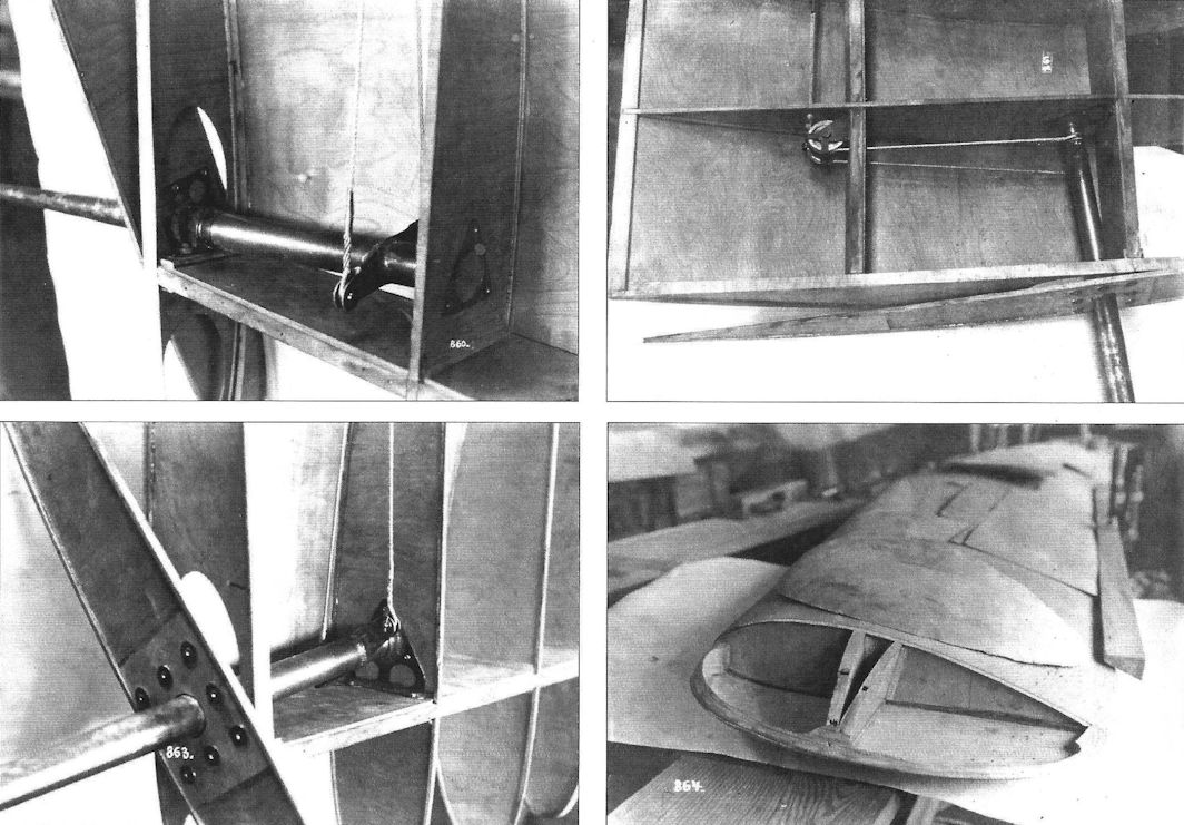
Fokker V.1 structural components, some undergoing strength testing.
-

J.Herris, T.Phillips - Fokker Aircraft of WWI. Vol.4: V.1-V.8, F.I & Dr.I /Centennial Perspective/ (54)
Fokker V.1 structure details.


-
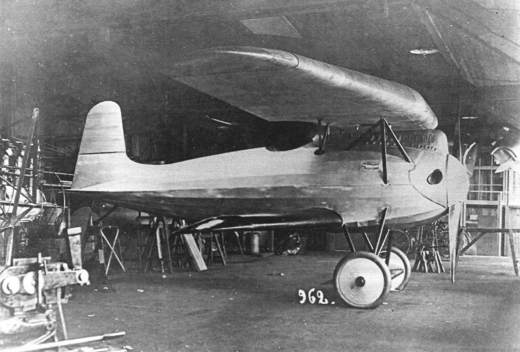
Форум - Breguet's Aircraft Challenge /WWW/
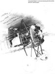
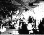
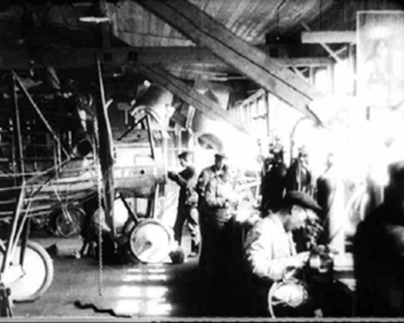
This is (an enlarged) still of the start of a movie shot in the experimental section of the Schwerin works of Fokker. At the right can be seen the craftsmen, probably the best of the Fokker factory. At the left in front you see the uncovered nose of the Fokker V.2 with in the background the covered fuselage of the Fokker V.1.
-
J.Herris, T.Phillips - Fokker Aircraft of WWI. Vol.4: V.1-V.8, F.I & Dr.I /Centennial Perspective/ (54)
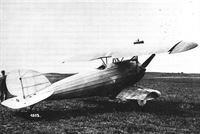
The Fokker V.2 was developed from the earlier V.1 but used the more powerful 160 hp Mercedes inline engine. It was larger and heavier than the V.1; despite its greater power the overall performance did not improve.
The Fokker V.2 in its original form, with low-set upper wing and rudder like that of the V.1. -
J.Herris, T.Phillips - Fokker Aircraft of WWI. Vol.4: V.1-V.8, F.I & Dr.I /Centennial Perspective/ (54)
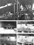
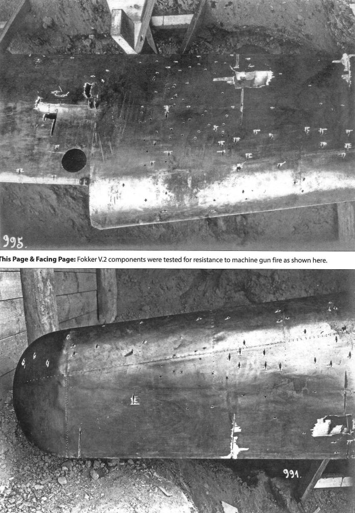
Fokker V.2 components were tested for resistance to machine gun fire as shown here.
-
J.Herris, T.Phillips - Fokker Aircraft of WWI. Vol.4: V.1-V.8, F.I & Dr.I /Centennial Perspective/ (54)
Fokker V.2 components were tested for resistance to machine gun fire as shown here.

-
J.Herris, T.Phillips - Fokker Aircraft of WWI. Vol.4: V.1-V.8, F.I & Dr.I /Centennial Perspective/ (54)
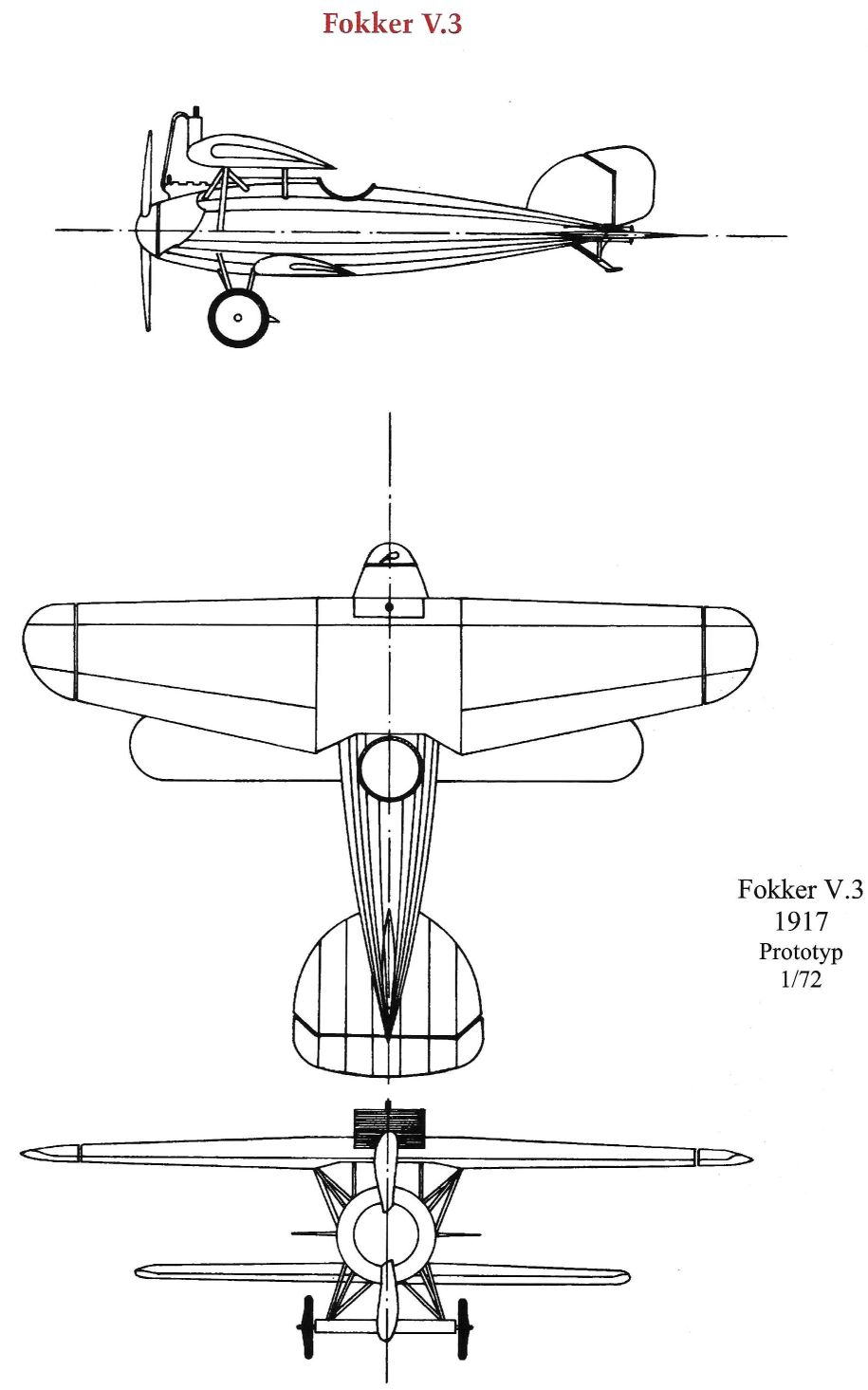
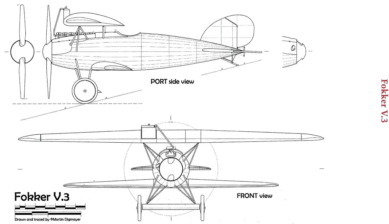
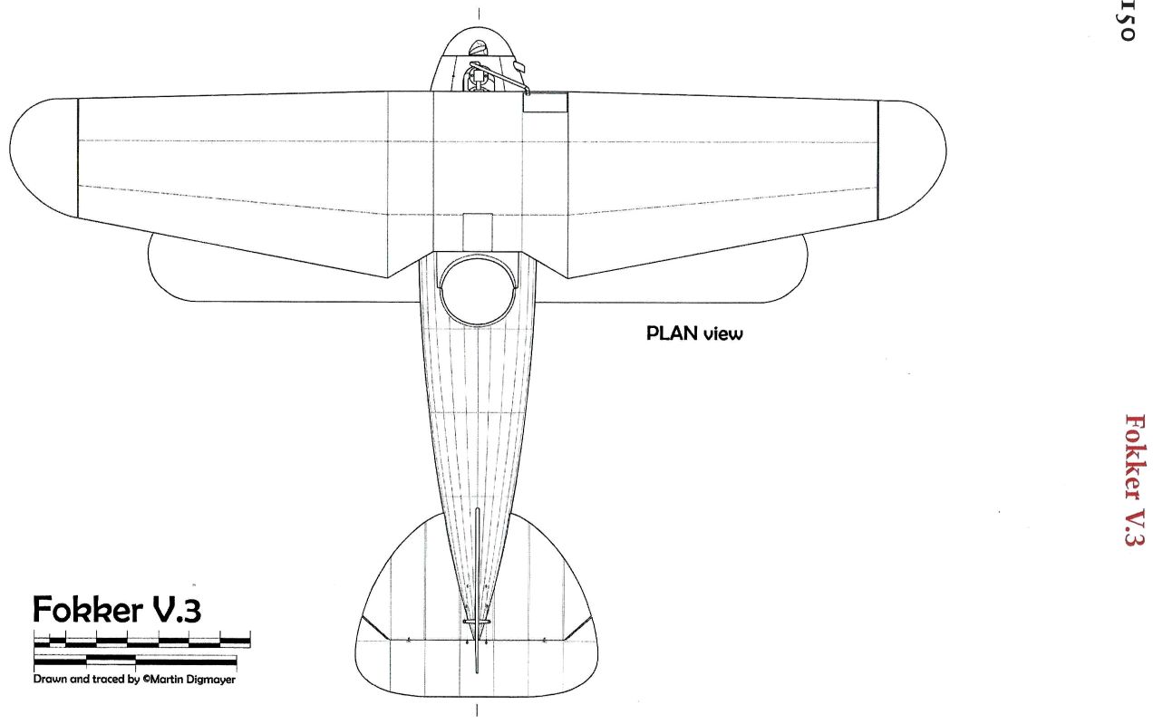
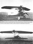
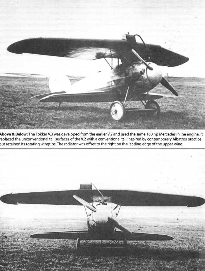
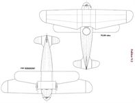
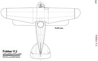
The Fokker V.3 was developed from the earlier V.2 and used the same 160 hp Mercedes inline engine. It replaced the unconventional tail surfaces of the V.2 with a conventional tail but retained its rotating wingtips.
-
J.Herris, T.Phillips - Fokker Aircraft of WWI. Vol.4: V.1-V.8, F.I & Dr.I /Centennial Perspective/ (54)
The Fokker V.3 was developed from the earlier V.2 and used the same 160 hp Mercedes inline engine. It replaced the unconventional tail surfaces of the V.2 with a conventional tail inspired by contemporary Albatros practice but retained its rotating wingtips. The radiator was offset to the right on the leading edge of the upper wing.
-
J.Herris, T.Phillips - Fokker Aircraft of WWI. Vol.4: V.1-V.8, F.I & Dr.I /Centennial Perspective/ (54)
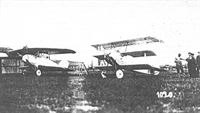
The Fokker V.3 on the left and the radically different V.5 Triplane, WN 1697, on the right.
Другие самолёты на фотографии: Fokker Dr.I (Fokker Dreidecker) / V4 / V5 / V7 - Германия - 1917
-
J.Herris, T.Phillips - Fokker Aircraft of WWI. Vol.4: V.1-V.8, F.I & Dr.I /Centennial Perspective/ (54)
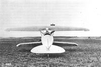
This rearview of the Fokker V.3 shows its rotating wingtips, Albatros-style tail, and bulbous streamlining.
-
J.Herris, T.Phillips - Fokker Aircraft of WWI. Vol.4: V.1-V.8, F.I & Dr.I /Centennial Perspective/ (54)
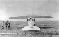
This view of the Fokker V.3 shows it now fitted with two external radiators mounted on the fuselage that significantly reduced its aerodynamic qualities. It still retained its rotating wingtips that were never used on a production Fokker.
-


-
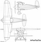
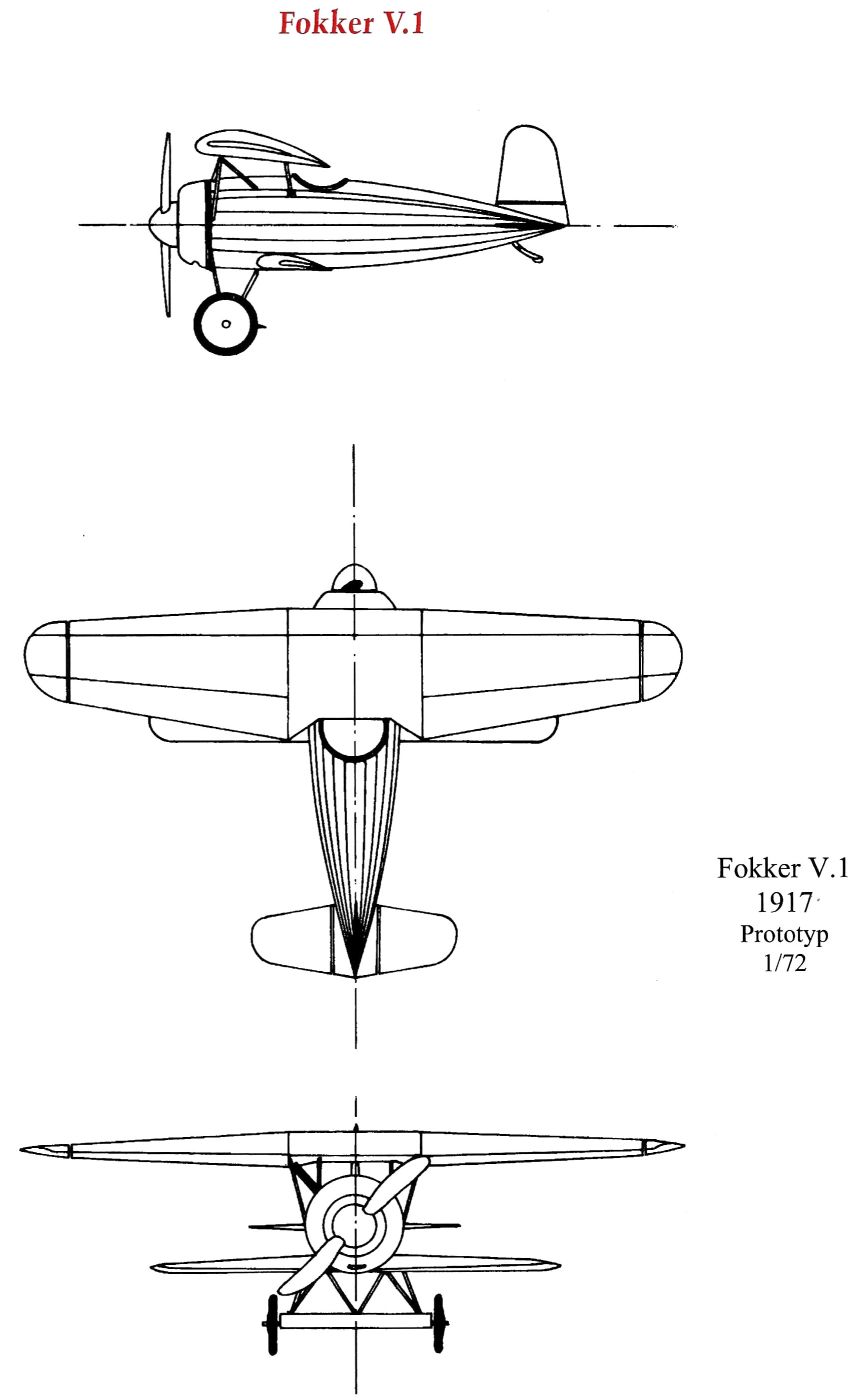
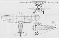
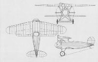
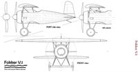
A.Weyl - Fokker: The Creative Years /Putnam/
Fokker V.1
-
-
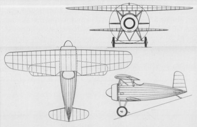
W.Green, G.Swanborough - The Complete Book of Fighters
The V 1 was a radical cantilever sesquiplane, designed by Reinhold Platz, which began its flight test programme in December 1916.
-
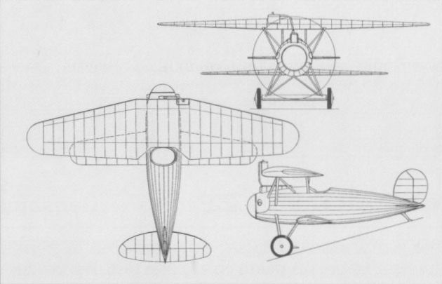
W.Green, G.Swanborough - The Complete Book of Fighters
Utilising experience gained with the V 1 and V 2, the V 3 allegedly possessed handling characteristics "too difficult" for frontline pilots.
-

-

-
-

-

-

-
-

-
-