P.Lewis British Aircraft 1809-1914 (Putnam)
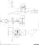
White and Thompson Single-engine Flying-boat
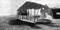
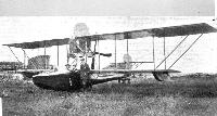
Among the nine entrants in the 1914 Daily Mail Circuit of Britain Contest, the two White and Thompson machines were unique as flying-boats, the remainder being floatplanes.
Entered as No. 6 in the race, for piloting by Captain Ernest C. Bass, the single-engined flying-boat was designated Seaplane No. 2 by the Company and was fitted with a 120 h.p. Beardmore-built Austro-Daimler on loan, which was mounted as a pusher. The design was based broadly on the American Curtiss type of flying-boat, for which White and Thompson had been granted the rights in the United Kingdom. Various modifications were made to the original Curtiss design, and among the less obvious of these was a change in wing section to one close in profile to R.A.F.6.
The two-bay wings were mounted on a hull 24 ft. long which was constructed by S. E. Saunders Ltd., at Cowes, Isle of Wight, and consisted of an ash and spruce frame covered with their Consuta skin composed of mahogany plywood sewn with copper wire. The crew of two were seated side-by-side, and the fuel was pumped to the engine from a tank situated in the hull. A cut-out was made in the upper wings to accommodate the four-bladed propeller, and the lower wings carried rectangular-section tip floats fitted with springboard protectors. Lateral control surfaces consisted of ailerons on the upper planes, on the centre section of which was fixed a single central fin which was carried in addition to the main tail fin which extended forward well along the hull. The rudder was metal-covered at its base and was used in the water for taxying.
The advent of the 1914-18 War caused the cancellation of the Circuit of Britain for which the machine was intended, but the flying-boat was completed and flown successfully on 9th August, 1914, proving that it possessed a brisk performance and good flying qualities. Few subsequent modifications were called for, and the prototype was bought by the Admiralty, later production versions seeing service with the R.N.A.S. as the White and Thompson No. 3, armament consisting of a Lewis gun for the observer. On the first production batch of six, the single fin above the wings was replaced by a pair of surfaces of lower aspect ratio which were mounted above the inboard interplane struts. On the next batch, these two fins were moved outboard so that they were over the outer wing-struts.
SPECIFICATION
Description: Two-seat pusher biplane flying-boat. Wooden structure, fabric covered.
Manufacturers: White and Thompson, Co. Ltd., Middleton-on-Sea, Bognor, Sussex.
Power Plant: 120 h.p. Beardmore-built Austro-Daimler.
Dimensions: Span, 45 ft. Length, 27 ft. 6 ins. Wing area, 400 sq. ft.
Weights: Empty, 1,600 lb. Loaded, 2,400 lb.
Performance: Maximum speed, 85 m.p.h. Endurance, 6 hrs.
Показать полностью
M.Goodall, A.Tagg British Aircraft before the Great War (Schiffer)
Deleted by request of (c)Schiffer Publishing
W&T: CURTISS type flying boats
Initially acting as an agency for the Curtiss-made boats, White and Thompson imported a few (possibly two machines), for sale and for setting up a flying training school at Middleton. The experience with the demonstration machine revealed shortcomings in design and construction which the firm decided could be improved upon. The emphasis thus became more on building improved English boats, rather than importing from America.
Changes were also incorporated in the demonstration machine, particularly the replacement of the seat back yoke for lateral control with a more conventional system. This machine was sold to Ernest Bass and taken to the south of France in the spring of 1914, but was crashed badly and returned to Middleton for rebuilding. This work included replacing the Curtiss type wings, fitted with midgap ailerons, with improved units of a new section and with ailerons in the top wings. A 100hp Anzani engine, instead of the Curtiss OX, was fitted and the machine, then referred to as the Bass-Curtiss Airboat, showed a marked improvement in performance.
White and Thompson constructed their first machine incorporating changes, and this was flown on the 27 March 1914 by J.C. Porte at Middleton. The hull had provision for four people ahead of the lower wing, in the wide forward portion, which tapered aft to a vertical knife edge. The underside was flat tapering to a vee bottom at the single step, behind which the hull bottom was flat. The top of the hull was raised in front of the crew, for protection against wind and spray. The structure was an ash framework covered with two layers of mahogany planking, with the addition of a waterproofed canvas interlayer in the planing bottom. Bulkheads were arranged to provide watertight compartments. Dual controls were fitted.
The wings were divided into two bays, outboard of the center section struts, and the top wing had overhang braced by a strut, cables and kingposts. A large cutout for clearing the propeller was provided in the top wing. Ailerons, whose area extended mostly behind the wing trailing edge, were fitted in the top wing only.
Flatsided metal wing tip floats were fitted flush to the underside of the wing and had a ski-shaped springboard to cushion the shock of alighting on water. A tail skid served to protect the hull when the boat was being moved on land, and the main hull was fitted with an external keel for similar protection.
The engine was positioned on a mounting of struts high in the gap, and was also braced forward by a strong diagonal member. The main fuel tank was under the rear seat, the fuel being raised by an engine driven pump.
The tail unit consisted of a long triangular fin and partly balanced rudder, which was reinforced and covered with copper sheet to form a water rudder. The triangular tailplane was set at a negative angle to offset the high thrust line and was raised above the hull on a steel tube mounting and carried a divided elevator.
Power: 100hp Curtiss OX5 eight-cylinder water-cooled vee driving a 8ft diameter two-bladed propeller.
Data
Span top 41ft
Span bottom 30ft
Chord top 5ft 3in
Chord bottom 5ft
Area 378 sq. ft
Area tailplane 27 sq. ft
Area elevators 24 sq. ft
Area fin 10 sq. ft
Area rudder 13 sq. ft
Gap 5ft 6in
Length 27ft 4in
Max speed 60 mph
Curtiss type F 'The Bass-Curtiss Airboat' (W&T reconstruction)
Power: 100hp Anzani six-cylinder air-cooled radial.
Data
Span 41ft 8in
Chord 5ft 6in
Gap 5ft 6in
Length 26ft
WHITE & THOMPSON flying boat 'Seaplane No.2'
This single-engined machine built in 1914 was also entered for the Seaplane Circuit of Britain which was abandoned. It carried entry No.6 on the rudder and 'Seaplane No.2' on the fin. As with No.I, it was taken over by the Admiralty under Contract No.CP53624/I4 for ?2,400, becoming serial No.882. The aircraft first flew on 1 August 1914 and, after service at various stations, was wrecked on 8 June 1915.
Although basically of Curtiss design, a number of modifications were made. The wings, of RAF 6 section with squarecut tips, were transferred from the Bass-Curtiss Airboat. The top wing carried a new rounded fin on the centerline, serving also as a king post for bracing wires; the outboard kingposts and bracing wires were deleted. Conventional ailerons were fitted to the top wing only. The hull, built by S.E. Saunders & Co. of Cowes, was covered with two skins of mahogany with an interlayer, and was sewn by the 'Consuta' method. At the front the decking was rounded, the greater width at the top tapering down to a vee bottom, which continued to the step. Aft of this, the hull was of round section with a flat top. No tail skid was fitted and detachable wheels were provided for ground handling. There was a general scaling up of dimensions and more power was provided.
Power: 120hp Austro-Daimler built by Beardmore driving a four-bladed propeller.
Data
Span top 45ft
Span bottom 34ft
Chord 5ft 6in
Gap 5ft 9in
Area 400 sq. ft
Area tailplane 30 sq. ft
Area elevators 27 sq. ft
Area fin 12 sq. ft
Area rudder 16 sq. ft
Length 27ft 6in
Weight 1,600 lb.
Weight allup 2,400 lb.
Max speed 70 mph
Endurance 6 hr
Показать полностью
Журнал Flight
Flight, April 11, 1914.
THE 100 H.P. CURTISS FLYING BOAT,
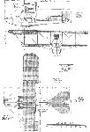
WE have from time to time had occasion to describe various types of Curtiss flying boats. The subject of our scale drawings this week is the 100 horse-power English Curtiss flying boat, the rights for which, it will be remembered, are held by Messrs. White and Thompson, of Bognor. Since his return from the States, Lieut. J. Porte has, we understand, been testing this machine, and she appears to be well up to the usual high standard of sea air worthiness which has made these machines so popular in America. The boat itself is of the usual well-known Curtiss type, having a rather wide nose and tapering to a short vertical knife's edge at the stern. In the nose the bottom of the boat is perfectly flat, running gradually into a V bottom at the step, whilst the rear portion of the hull behind the step is flat. The sides of the boat slope outwards in the front portion, and there is an unusually high freeboard, which protects the occupants against water spray. From the nose of the boat a super-structure forming a wind shield runs back to a point just in front of the pilot's seat.
Constructionally the boat is built up over a framework of ash, spaced on three-inch centres, mortised at the corners, fitted with copper corner straps and each frame securely fastened with sixteen copper rivets. Longitudinal ribs or battens of one-inch square ash are run throughout the whole length of the hull. The sides of the boat are covered with a planking consisting of two layers of mahogany, whilst the bottom is triple-sheathed with first a planking of 5/16 in. mahogany, then a covering of heavy canvas set in marine glue and an outer planking of 1/4 in. mahogany. This planking runs diagonally, and extends back to the step only, the rear portion of the hull taking only a slight part of the load in rising and alighting. Eight bulkheads divide the boat into watertight compartments, so that it is practically unsinkable, for any two of the compartments are claimed to possess sufficient buoyancy to keep the entire machine afloat.
The workmanship as well as the finish of the boat is of a very high quality, and one regrets that Messrs. White and Thompson could not find the time to exhibit the machine at the recent Olympia Aero Show, where it would certainly have attracted a great deal of attention.
Two sets of seats are provided - one set for the pilot, or rather pilots, arranged side by side in front of the leading edge of the lower main plane, and another set between the leading edge and the rear spar at the lower main plane. The pilot's cockpit is unusually roomy and comfortable, and the view obtained from there is practically unobstructed in all directions. Dual control is fitted, and consists of two rotatable hand wheels, each mounted on a short forked arm which joins the vertical tubular column. This in turn is mounted on a transverse rocking-shaft projecting outside the sides of the boat, where are carried the crank levers from which cables run to the elevator. The rudder is operated by means of a pivoted footbar.
The lower plane is bolted to the gunwales of the boat from which it is stayed by means of cables. Six pairs of inter-plane struts of spruce separate the main planes, of which the upper one possesses a considerable overhang, the weight of which is taken, when the machine is at rest, partly by a steel tube running from the lower end of the outer rear strut to the end of the extension and partly by cables passing over a king post above and on the front spar of the wing.
It will be remembered that the usual Curtiss lateral control consists of two ailerons mounted on the struts in the gap between the planes. In this machine ailerons of a more orthodox type are fitted to the trailing edge of the outer portion of the upper main plane. From the accompanying scale drawings of the machine it will be seen that the two main spars are set very far apart, the front one forming the leading edge whilst the rear one is placed very close to the trailing edge of the wing.
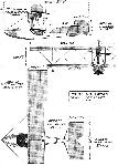
Metal floats of the shape shown in one of the accompanying sketches prevent the wing tips of the lower main plane from cutting under. The bottom of these floats is protected against too harsh a contact with the water by means of a spring board which is secured to the nose of the float, but the rear end of which is allowed a certain amount of play in the manner shown in the sketch.
An extension of the stern post of the hull serves as a support for the partly-balanced rudder and the vertical fixed tail fin. The lower portion of the rudder is covered with wood and copper bound in order to allow of steering the machine at low speed on the water. A tail skid or skeg protects the tail planes when the machine is being beached. The fixed tail plane, which is triangular, as seen in plan, is carried on a structure of steel tubes secured to the rear portion of the hull, and to its trailing edge is hinged the divided elevator.
An outside keel in the form of a wooden strip runs along the entire length of the boat, thus protecting the bottom when running the machine up on the beach, and it is even possible, we understand, to run the machine from the hangar down to the beach by taxying along the grass on this keel.
The engine, a 100 h.p. 8-cylinder V type Curtiss, is mounted on two longitudinal ash bearers supported on a structure of welded steel tubing between the main planes. It drives directly a Curtiss propeller situated immediately behind the rear spar of the upper plane, the trailing edge of which has been cut away to provide clearance for the propeller. A very stout oblique strut runs from the engine bearers down to the bottom of the forward portion of the boat, the purpose of this strut obviously being to transmit the momentum of the engine to the boat on alighting.
The main petrol tank is situated in the boat under the rear pair of seats, whence it is forced to a small service tank between the radiator and engine by means of a small pump driven off the engine. The radiator is mounted immediately in front of the engine on extensions of the longitudinal engine bearers, a rd projecting in front of it is a starting-handle by means of which the engine can be started from the pilot's seat. It should be noted that this starting-handle does not clear the oblique strut, as it would not be possible from the pilot's seat to give the starting-handle a whole turn. For starting the engine the handle is simply put in a position slightly above the horizontal and pulled down smartly, an operation which is generally sufficient to get an explosion in one of the cylinders.
The speed of the machine with full load is about sixty miles per hour, whilst we understand it is possible to taxy it along the water at any speed up to forty miles per hour.
When taxying at this speed only a small portion of the hull just in front of the step is in contact with the water.
Flight, September 11, 1914.
THE "ROUND BRITAIN" MACHINES.
THE machine numbered 6 in the Circuit of Britain, and which was to have been piloted by Capt E. C. Bass, is
The White and Thompson Curtiss Flying Boat.
This machine, although following standard Curtiss practice in its general lay out, differs in numerous details from the American-built Curtiss boats. One of the innovations incorporated, which is apt to be overlooked by the casual observer, but which is nevertheless of the greatest importance, is the new wing section. Instead of the usual Curtiss section, one like the R.A.F. 6 has been chosen, and appears to have several advantages over the original Curtiss. The wings are rectangular, as seen in plan, and the top plane is of considerably greater span than the lower one, the weight of the extensions being taken, when the machine is at rest, by steel tubes sloping downwards and inwards to the lower extremities of the outer inter-plane struts. Interconnected balancing flaps are hinged to the rear spar of the upper plane, and not, as in the original Curtiss machines, to the plane struts.
A vertical fin is fitted above the upper main plane in order, no doubt, to counteract the comparatively large side area of the boat. Six pairs of spruce struts separate the main planes, the whole wing structure being made rigid by diagonal cross bracing.
Mounted on strong ash bearers resting on a structure of steel tubes sloping upwards from the lower main spars is the engine - a 120 h.p. Beardmore A.D. - which drives a four-bladed propeller situated behind the planes, the trailing edge of which has been cut away in the centre to provide the necessary clearance. The main petrol tank is placed inside the boat, whence petrol is pumped by means of a pressure pump to a smaller service tank mounted on the bearers in front of the engine. The capacity of the petrol tank is 60 gallons, or sufficient for a flight of about six hours' duration.
The boat, which has been constructed by Messrs. Saunders of Cowes, is a beautiful piece of work, as is to be expected from a firm of such standing. It is built up of two skins of mahogany, copper sewn, over a framework of ash and spruce. In front the boat is of roomy proportions, and affords ample accommodation for pilot and passenger, who sit side by side inside a very comfortable cockpit. From the nose to the step, which is placed a short distance behind the front spar of the wings, the boat has a Vee bottom and outward sloping sides. To the rear of the step the section may be described as being circular with a flat top. In front of the occupants the boat is covered with a curved deck, which allows any water that may wash over the top to run off easily, whilst just in front of the cockpit the deck is swept upwards to form a wind screen.
As dual controls are fitted, pilot and passenger may direct in turn, a feature which should be of great value for long flights. The controls consist of rotatable hand wheels operating the ailerons and elevator, and foot bars for the rudder. A transverse rocking shaft runs across the boat and projects on each side, where it carries the crank levers whence cables are taken to the elevator.
Mounted under the lower wing tips, to which they are attached by steel clips, are two metal floats of rectangular section and having flat bottoms, which are protected by spring boards of wood, screwed to the front of the floats and having their rear ends free to move slightly up and down.
The tail planes are of the usual Curtiss type, and consist, as will be seen from the accompanying illustrations, of a large vertical fin screwed to the top of the rear portion of the boat and braced by steel tubes, a partly balanced rudder, a fixed stabilizing plane mounted on top of the fin, and a divided elevator. The lower portion of the rudder is covered with metal and serves as a water rudder when taxying.
The weight of the machine empty is 1,600 lbs., and with full load, including pilot, passenger, and six hours' fuel, the weight is 2,400 lbs., giving a loading of 6 lbs. per sq. ft. The actual speed is not known, but judging from previous Curtiss boats and making allowance for the higher horse-power and new wing section, it is probably about 70 m.p.h.
Показать полностью


