J.Bruce British Aeroplanes 1914-1918 (Putnam)
London and Provincial School Biplane Type No. 4
THE London and Provincial Aviation Co. operated a flying school at Hendon aerodrome from 1914 onwards. The company built some training machines of the Caudron type for use at their school.
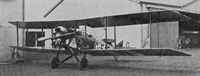
In 1916, A. A. Fletcher left the Martinsyde concern to join the London and Provincial company, and he designed two trainer aircraft for his new firm. The first of these was a small and thoroughly conventional little two-bay biplane, powered by a 50 h.p. Gnome rotary engine, and known as the London and Provincial Type No. 4.
The London and Provincial concern later moved to their own aerodrome at Edgware, and it was there that the machine was flown.
After the Armistice, the London and Provincial company tried to market the little Gnome-powered biplane as a cheap aeroplane powered by an engine which was easily obtainable. Unfortunately, the Gnome’s lack of dual ignition led to the A.I.D.’s refusal to approve the aircraft, and production could not be undertaken.
SPECIFICATION
Manufacturers: The London and Provincial Aviation Co., Edgware, London, N.
Power: 50 h.p. Gnome.
Dimensions: Span: 32 ft 6 in. Length: 25 ft 3 in. Height: 8 ft gin. Chord: 4 ft 74 in. Gap: 5 ft. Span of tail: 10 ft 6 in. Airscrew diameter: 7 ft.
Areas: .Wings: 280 sq ft. Ailerons: each 10 sq ft, total 40 sq ft. Tailplane: 24-75 sq ft. Elevators: 16-25 sq ft. Fin: 3 sq ft. Rudder: 6 sq ft.
Weights: Empty: 655 lb. Loaded: 1,070 lb.
Performance: Maximum speed at ground level: 60 m.p.h. Climb to 5,000 ft: 20 min. Endurance: 11 1/2 hours.
Tankage: Petrol: 8 gallons. Oil: 4 gallons.
London and Provincial School Biplane
DEVELOPED from the Gnome-powered London and Provincial Type No. 4 was the larger two-seater with the 80 h.p. Anzani radial engine: it appeared in the middle of 1916. The later machine displayed several characteristics which combined to produce a certain likeness to Fletcher’s earlier design, the Martinsyde Elephant.
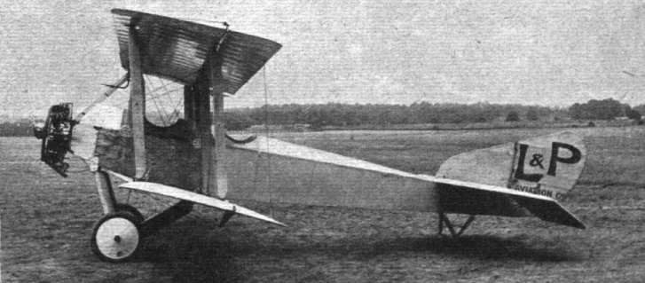
In construction, the Anzani-powered London and Provincial biplane was typical of its period. The fuselage was basically of rectangular section with ash longerons; the forward portion had diagonal spruce struts for bracing and was covered with ash plywood, and the rear portion was cross-braced by wire in conventional fashion. A rounded top-decking was fitted.
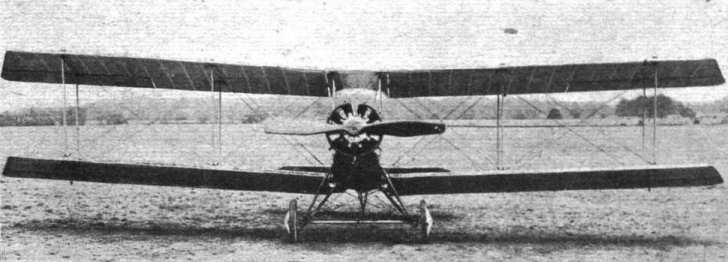
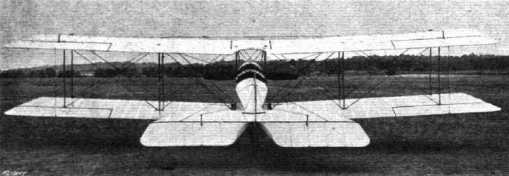
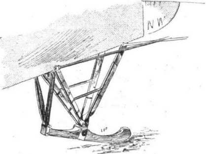
The equal-span wings were also of wooden construction and had sharply-raked tips: ailerons were fitted to upper and lower mainplanes. The tail surfaces were of generous area and conventional construction. The undercarriage was a simple vee structure consisting of two faired steel tube vees connected by two steel tube spreader-bars between which the axle lay. The wheel track was unusually wide, presumably to ensure ground stability in an aeroplane intended for use as a trainer.
The type was built in small numbers by the London and Provincial Aviation Co. for use at their own school, and the machine proved to have good flying qualities. It was quite manoeuvrable, and in the hands of G. Smiles set up a number of looping records at Hendon in 1916.
For experimental purposes, one of the London and Provincial machines was flown with a set of S.E.5 mainplanes strapped to the underside of its own lower wings. Presumably this was done to test the feasibility of transporting spares in this way; it is recorded that the London and Provincial biplane flew satisfactorily with its unusual load.
Later, the type was used in parachute experiments, and many jumps were made with “Guardian Angel” Parachutes. On July 10th, 1918, W. L. Wade, wearing one of these parachutes, made a live drop from an L. and P. Anzani biplane flying at 400 feet. The aeroplane was flown by Captain R. Payze, R.A.F.
Five London and Provincial biplanes came on to the British Civil Register after the Armistice. The machine which became G-EAQW was fitted with a 100 h.p. Anzani instead of the original 80 h.p. engine.
SPECIFICATION
Manufacturers: The London and Provincial Aviation Co., Edgware, London, N.
Power: 80 h.p. Anzani; 100 h.p. Anzani.
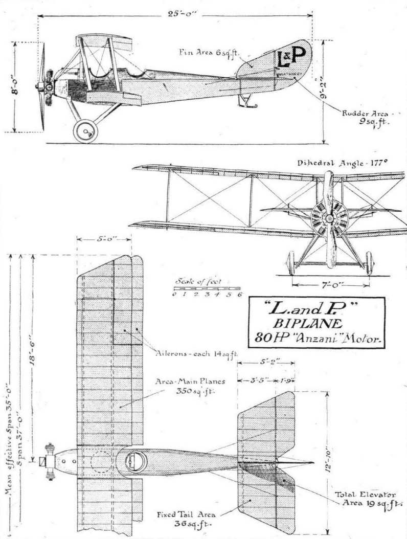
Dimensions: Span: 37 ft. Length: 25 ft. Chord: 5 ft. Gap: 5 ft. Dihedral: 1° 30'. Span of tail: 12 ft 10 in. Wheel track: 7 ft. Airscrew diameter: 8 ft.
Areas: Wings: 350 sq ft. Ailerons: each 14 sq ft, total 56 sq ft. Tailplane: 36 sq ft. Elevators: 19 sq ft. Fin: 6 sq ft. Rudder: 9 sq ft.
Weights (with 80 h.p. Anzani): Loaded: 1,400 lb.
Performance: Endurance: 3 hours.
Показать полностью
A.Jackson British Civil Aircraft since 1919 vol.3 (Putnam)
L. and P. Biplane
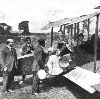
Two seater powered by one 50 h.p. Gnome, designed by A. A. Fletcher, built at Hendon 1916 by the London and Provincial Aviation Company as Type No.4 for their own flying school. After the 1914-18 war, five were registered for use at Stag Lane, Edgware: K-117/G-EABQ, c/n E121; K-118/G-EABR, c/n E120; K-119/G-EABS, c/n D147, all registered 20.5.19, broken up 8.19 when A.I.D. approval was refused. K-138/G-EADT, c/n E122, registered 11.6.19, crashed 10.20. Improved version G-EAQW, 100 h.p. Anzani (illustrated), no c/n, used during the 1914-18 war for parachuting experiments, registered to R. A. Whitehead 6.2.20, later sold to J. Coe and scrapped.
Span, 37 ft. 0 in. Length, 25 ft. 0 in. Duration 3 hours.
Показать полностью
Журнал Flight
Flight, July 27, 1916.
THE NEW L. AND P. FUSELAGE BIPLANE.
A VERY neat and clean design. This is the first impression received when viewing the new biplane built by the London and Provincial Aviation Co., of Hendon, and, as in so many other cases, closer acquaintance confirms the first impression. The designer of the machine, Mr. Fletcher, who previous to joining the L. and P. firm was associated with Messrs. Martin and Handasyde of Brooklands, has managed to incorporate into a very graceful outline design a number of cleverly thought out details, and the result is a machine combining everywhere the required, and in many places a greater, factor of safety with a minimum of weight. In this connection it might be pointed out that throughout the machine all fittings are so designed as to avoid piercing any of the important members subjected to stress, such as main wing spars, body rails, &c. It is by this means that it has been possible to cut down weight without sacrificing strength, and so well have the various fittings been thought out that nowhere has the designer had to resort to a clumsy, ungainly job to get around the objectionable drilling.
From the accompanying photographs and scale drawings a good idea can be formed of the general arrangement of the new L. and P. biplane, while some of the constructional details are shown in the various sketches. The body, which is of rectangular section, is probably of as good a streamline form as it is possible to obtain without the use of formers and stringers. It is built up of ash rails, tapering and spindled out towards the rear, and connected by vertical and horizontal struts. In the rear portion the bracing is effected by wiring, while in front where, as will be seen, the covering consists of three-ply ash bracing takes the form of diagonally placed spruce struts. The wiring plates connecting the struts to the rails in the rear part of the body are some of the most ingenious we have seen, being made up of three pieces of very light gauge, the three pieces being held together by the copper eyelets in the holes for the bracing wires. The fitting is quickly and cheaply made, being, as already mentioned, of very light gauge, and by making it in two standard sizes it can be employed irrespective of the taper of the body rails.
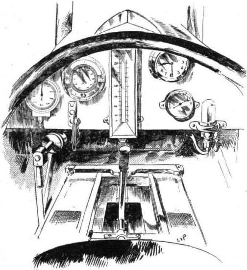
In front a number of the metal fittings take the form of large Duralumin plates serving a variety of purposes. Several of these plates can be seen in the illustrations. A turtle back, consisting in front of three-ply wood, and at the rear of formers and stringers, tops the body and helps to give the necessary depth for effectively enclosing the occupants, of whom nothing but the heads are seen when the machine is flying. The pilot occupies the back seat, and has in front of him a neatly fitted dashboard with all the usual instruments, including engine revolution counter, altimeter, air speed indicator, clock, petrol pressure gauge, telltale oil glass, &c. In front of the pilot, and in a separate cockpit, is installed the passenger, whose seat is placed on top of the main petrol tank, which in turn rests on the bottom of the body. From this tank the fuel is forced by means of a pressure pump to a smaller service tank in the nose of the body. The controls consist of a central lever of wood mounted on a longitudinal rocking shaft, and of a foot bar for the rudder.
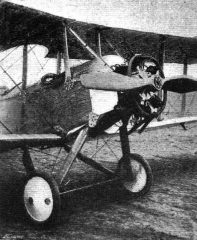
The engine - an 80 h.p. Anzani - is mounted in the usual manner on a capping plate bolted to the rails of the body. In order to further stiffen the mounting, two tubes are taken from the bolts of the crank-case to the top of the inner inter-plane struts. Just behind the engine the body is covered with aluminium plates, that of the top being neatly curved to form a better entry for the air.
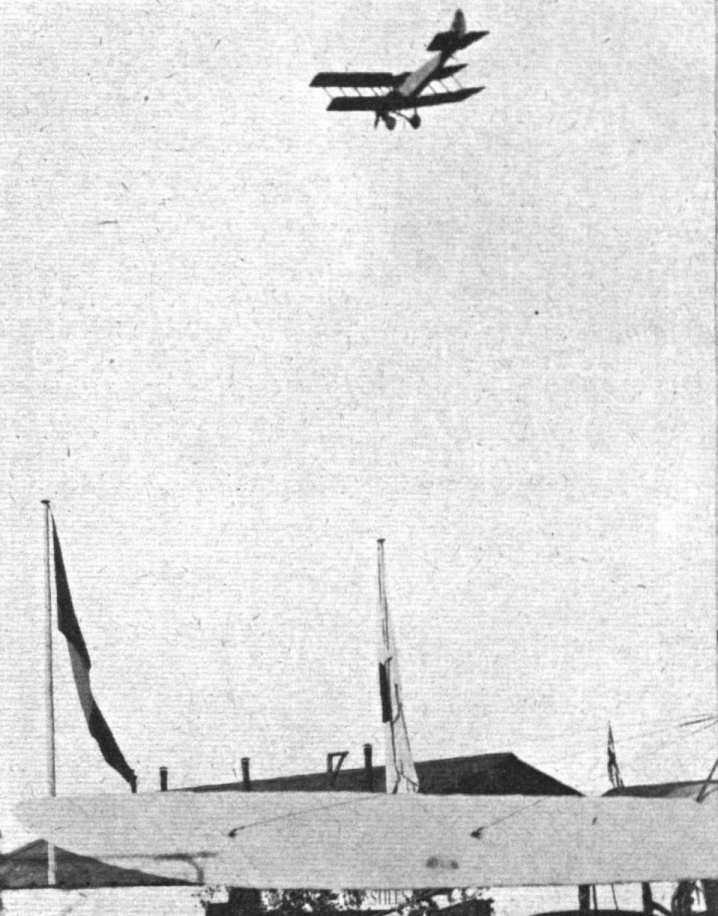
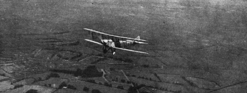
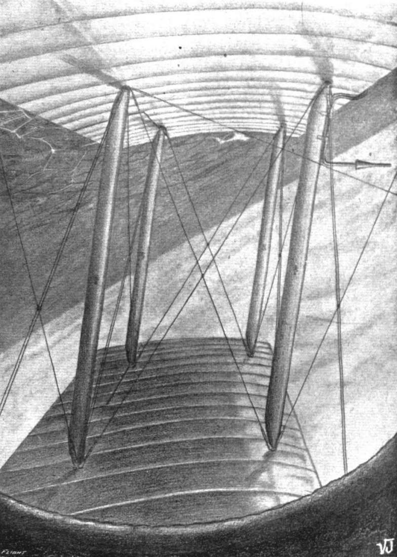
The main planes, which are of a section somewhat similar to the R.A.F. 6, with the exception that the lower surface is slightly more cambered, 2 1/2 in. to be exact, are characterised by heavily raked tips which tend to give the machine a "racy" appearance, and which perform the more useful function of decreasing end losses and increasing the effectiveness of the ailerons. The latter are fitted to both top and bottom planes, with the result that the machine has an ample margin of lateral control, as demonstrated a few days ago, when Mr. G. Smiles, accompanied by a passenger, put up some alarming banked turns, during which the wings were repeatedly in a vertical position.
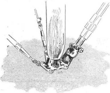
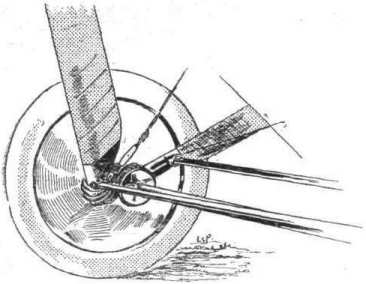
One of our sketches illustrates the attachment of the lower wing spars to short spars passing under the body.
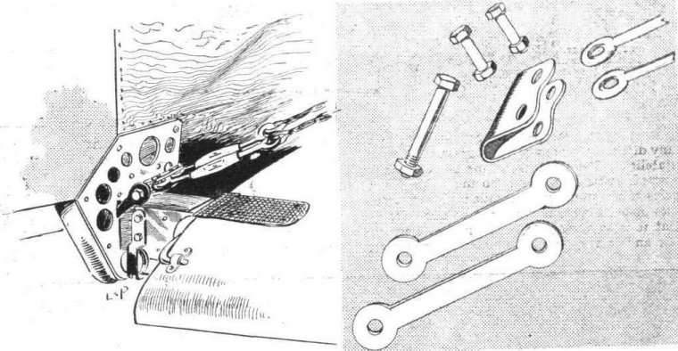
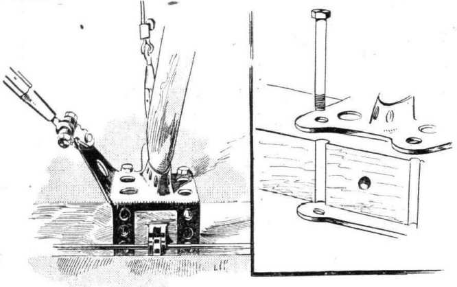
Let into each side of the centre spars is a plate, semi-circular at its outer end and angular at the inner end. Four bolts pass through each plate and through the spar. On the inner ends of the main wing spars are two similar plates, bolted to the spars in the same manner. These latter pass outside the plates on the centre spars, and a hinged joint is formed by a long hinge-pin passing through the central hole in the end of the plates from back to front spars. One end of this pin is bent over at right angles, and is prevented from coming adrift by a small aluminium clip passed over the bent end and screwed to the inner rib of the wing. In the same sketch is shown the anchorage for the lift cables. Two magnified chain-links are secured to the spars of the centre section of the lower plane by a sturdy bolt, and as the spars themselves are at this point of generous proportions, the stresses are adequately dealt with. Another point in favour of this method of passing the spars right underneath the body is that the final point of anchorage for the lift cables is immediately below the bottom rails of the body, so that no twisting strain is imposed on the rails. At the outer ends of the chain-links referred to above is another stout bolt around which passes a plate receiving the ends of the wire strainers in the manner shown in the sketch.
One of the features of the new L. and P. biplane is the type of wiring plate and inter-plane strut socket employed. One form of these consists of a rectangular plate to which the socket is welded, provided with the necessary lips for attachment of bracing cables. At each corner of this plate is a hole for a bolt passing through the wing and through a similar plate on the other side of the spar, minus the socket, of course. The four bolts on being tightened up cause the two plates to grip the spars, and the plates are further prevented from sliding along the spars on account of the obliquity of the bracing cables by letting the bolts, into the sides of the spars to the extent of half their diameters. The fitting used for the outer struts is similar, except that here only two bolts are employed, the place of the other two being taken by two strips, of the wiring plate itself bent around the side of the spar.
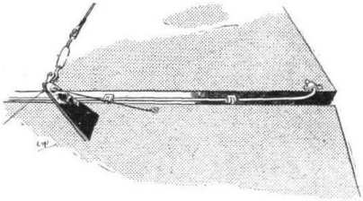
The hinge for the ailerons is formed by forked eye-bolts passing through the spars, and ordinary eyebolts in the leading edge of the aileron. A long wire bolt runs right through all the eyebolts, thus doing away with the ordinary short bolt and nut for each hinge, which would be somewhat inaccessible in the narrow slot between the rear spar and the aileron. An exactly similar hinge is employed for the rudder and elevators. Regarding the various members of the tail these give the impression of being unusually large, but from the severe tests of stability carried out recently it would appear that the control organs, while being large enough to ensure that any tendency to pitching or yawing is effectively stopped, are not so large as to cause any difficulty in the way of too great or weathercock stability. The fixed tail plane is of the nonlifting type in so far as it is set at no angle of incidence to the axis of the propeller, but while its lower surface is flat its upper surface is cambered to allow for the fact that it is working in the slip stream from the propeller and in the down draft from the wings. A small swivelling skid mounted on a pyramid of steel tubes, streamlined with wood fairings, protects the tail planes against contact with the ground.
When looking casually at the machine, the chassis appears to consist of four streamline wood struts supporting the axle, but on closer examination it is found that the struts are in reality steel tubes encased in a fairing of wood. Two transverse steel tubes connect the lower apices of the Vees formed by the chassis struts, and the Duralumin tubular axle is slung from the tubular struts by rubber cord.
Altogether the London and Provincial Aviation Co. are to be congratulated on their first machine of original design. The workmanship is such as no large firm would need be ashamed of, in fact it would be difficult to improve on it, and the designer, Mr. Fletcher, has good cause to be proud of the machine from an aerodynamical as well as from a constructional point of view, seeing that it has already done some very excellent performances, including looping with two up, although the engine was far from being in concert trim, ticking, in fact, over at somewhere in the neighbourhood of 900 r.p.m. instead of the regulation 1,250. Even so the speed was something like 75 m.p.h., and when the new Lang propeller ordered for the machine arrives, this figure is expected to be considerably exceeded. The total weight "all up," including pilot, passenger, and three hours' fuel, is 1,400 lbs., which is very light for a machine of this size. We have no official figures regarding the gliding angle, but it appears to be extraordinarily good, probably in the neighbourhood of 1 in 10.
Показать полностью