Описание
Страна: Германия
Год: 1916
Варианты
- Albatros - C.V - 1916 - Германия
- Albatros - C.VII - 1916 - Германия
- В.Кондратьев Самолеты первой мировой войны
- O.Thetford, P.Gray German Aircraft of the First World War (Putnam)
- J.Herris Albatros Aircraft of WWI. Vol 2: Late Two-Seaters (A Centennial Perspective on Great War Airplanes 25)
- Журнал Flight
-

J.Herris - Albatros Aircraft of WWI. Volume 2: Late Two-Seaters /Centennial Perspective/ (25)
Albatros C.V/16 C.1176/16 of Flieger-Abteilung 2. Although shown as plain fabric, the upper wing surfaces were possibly in the three-tone scheme.
-

J.Herris - Albatros Aircraft of WWI. Volume 2: Late Two-Seaters /Centennial Perspective/ (25)
Albatros C.V/16 C.1220/16 flown by Lt. Albert Dossenbach & Oblt. Hans Schilling, FFA 22, September 1916.
-

J.Herris - Albatros Aircraft of WWI. Volume 2: Late Two-Seaters /Centennial Perspective/ (25)
Albatros C.V/16 C.1257/16, unit unknown. Although shown with dark stained fuselage, this aircraft may have had the fuselage painted in camouflage colors. The serial was repeated on the nose in white and is assumed to be on the fin.
-

J.Herris - Albatros Aircraft of WWI. Volume 2: Late Two-Seaters /Centennial Perspective/ (25)
Albatros C.V/16 of Flieger-Abteilung 2. The upper wing surfaces appear to be painted in the three-tone scheme.
-

J.Herris - Albatros Aircraft of WWI. Volume 2: Late Two-Seaters /Centennial Perspective/ (25)
Albatros C.V/16 of Flieger-Abteilung (A) 261. Flown by Vzfw. Fritz Kosmahl, the unit mechanics fitted a captured Vickers machine gun in addition to the standard fixed Spandau. The upper wing surfaces are depicted in the three-tone scheme but may have been in plain finish.
-

J.Herris - Albatros Aircraft of WWI. Volume 2: Late Two-Seaters /Centennial Perspective/ (25)
Albatros C.V/16, unit unknown. Although shown as plain fabric finished, the upper wing surfaces were possibly in the three-tone scheme.
-

J.Herris - Albatros Aircraft of WWI. Volume 2: Late Two-Seaters /Centennial Perspective/ (25)
Albatros C.V/16, unit unknown, circa 1917.
-

J.Herris - Albatros Aircraft of WWI. Volume 2: Late Two-Seaters /Centennial Perspective/ (25)
Albatros C.V/16 of Flieger Abteilung 270Lb. Photographed on its nose, the aircraft was a uniform color under its wings and tail and a darker uniform color on upper surfaces, depicted here as feldgrau above with light blue below. The fuselage marking was black and white.
-
В.Обухович, А.Никифоров - Самолеты Первой Мировой войны
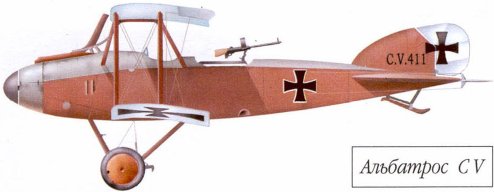
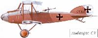
Альбатрос C.V
-

J.Herris - Albatros Aircraft of WWI. Volume 2: Late Two-Seaters /Centennial Perspective/ (25)
Albatros C.V/17 1371/17 of Flieger-Abteilung 7 with that unit's distinctive arrow markings on the fuselage sides and upper surface. Tactical number '6' was applied forward of the arrow.
-

J.Herris - Albatros Aircraft of WWI. Volume 2: Late Two-Seaters /Centennial Perspective/ (25)
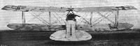
The streamlined Albatros C.V was the first of the second-generation Albatros C-type designs to reach the front. It was also the only C-type without a six-cylinder engine; the C.V used the 220 hp Mercedes D.IV, a straight-eight cylinder engine created by adding two more cylinders to the 160 hp Mercedes D.III.The propeller reduction gear raised the thrust line of the propeller, enabling the engine to be fully cowled. The reduction gear also reduced propeller speed, enabling a large, slow-turning propeller to befitted for maximum efficiency and greater speed. This aircraft was one of the three C.V prototypes from the batch C3593-3595/15 and was photographed in front of the Albatros factory in March/April 1916. The external, over-wing gravity tank was not fitted to production aircraft.
-

J.Herris - Development of German Warplanes in WWI /Centennial Perspective/ (1)
Like the LVG C.IV, the Albatros C.V was powered by the 220 hp Mercedes D.IV straight-eight engine, was faster than Allied fighters when it reached the front, and was used for photo reconnaissance.
-

J.Herris - Albatros Aircraft of WWI. Volume 2: Late Two-Seaters /Centennial Perspective/ (25)
A prototype Albatros C.V in front of the Albatros factory at Johannisthal illustrates the characteristic features. The prototypes had a wingspan of 12.2 meters; production aircraft had a longer, 12.78 meter span. The exhaust stack has a different shape than production aircraft, and there is no fixed gun for the pilot.There is also an external gravity tank over the upper wing that was not present in production aircraft and the observer's gun ring is recessed. (Peter M. Bowers Collection/The Museum of Flight)
-

J.Herris - Albatros Aircraft of WWI. Volume 2: Late Two-Seaters /Centennial Perspective/ (25)
Albatros C.V prototype 3595/15 after a poor landing.
-

J.Herris - Albatros Aircraft of WWI. Volume 2: Late Two-Seaters /Centennial Perspective/ (25)
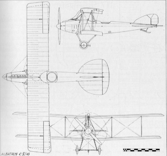
Albatros C/16 1176/16 was the second production aircraft; it was photographed during a quiet moment in the field at FliegerAbteilung 2. The aircraft has the early production series features of squared wingtips on the lower wings, ear radiators, and coolant header tank over the engine. The large (3.4 meter diameter), slow-turning propeller used with the geared Mercedes D.IV was also a distinctive C.V characteristic.
-

J.Herris - Albatros Aircraft of WWI. Volume 2: Late Two-Seaters /Centennial Perspective/ (25)
C.V/16 1176/16 of FA 2 before the wheel covers were painted shows its massive engine and nose details.
-

J.Herris - Albatros Aircraft of WWI. Volume 2: Late Two-Seaters /Centennial Perspective/ (25)
Albatros C.V/16 C.1176/16 assigned to FliegerAbteilung 2 runs up its engine. (Courtesy Bruno Schmaling)
-

J.Herris - Albatros Aircraft of WWI. Volume 2: Late Two-Seaters /Centennial Perspective/ (25)
C.V/16 1176/16 of FliegerAbteilung 2 flying low shows off its newly-decorated wheel covers. The characteristic Albatros semi-monocoque fuselage made of plywood shows up nicely.
-

J.Herris - Albatros Aircraft of WWI. Volume 2: Late Two-Seaters /Centennial Perspective/ (25)
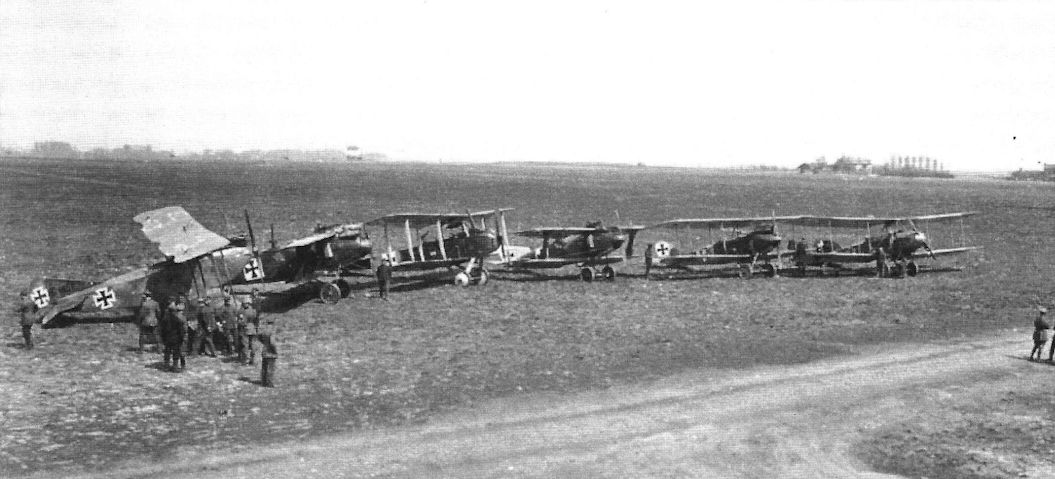
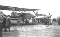
FliegerAbteilung 3b photographed with a captured Nieuport fighter. The dark Albatros C.V/16 at left may be C.1177/16 and second in line is C.V/16 C.1262/16 followed by three unidentified Albatros C.VII two-seaters. The occasion appears to be an awards ceremony, and the position of the Nieuport indicates the ceremony may be related to its capture. (Courtesy Bruno Schmaling)
Другие самолёты на фотографии: Albatros C.VII - Германия - 1916Nieuport Nieuport-17bis/24/27 - Франция - 1917
-

J.Herris - Albatros Aircraft of WWI. Volume 2: Late Two-Seaters /Centennial Perspective/ (25)
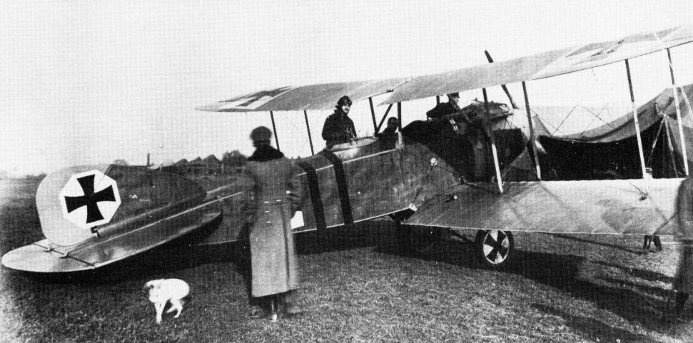
Albatros C.V/16 C.1179/16 of Feld FliegerAbteilung 1 photographed with aircrew. In contrast to many anonymous Albatros C.V aircraft, the serial is clearly painted on both the fuselage and fin. (Courtesy Bruno Schmaling)
-

J.Herris - Albatros Aircraft of WWI. Volume 2: Late Two-Seaters /Centennial Perspective/ (25)
Albatros C.V/16 C.1179/16 of Feld FliegerAbteilung 1 with three men aboard and engine running. The tail is up on a trestle and too many men are aboard for flight; is this maintenance in progress? (Courtesy Bruno Schmaling)
-

J.Herris - Albatros Aircraft of WWI. Volume 2: Late Two-Seaters /Centennial Perspective/ (25)
Albatros C.V/16 1180/16 of Feld-Flieger Abteilung 25. The observer, Oblt. Graf von Schaesburg-Thannheim, has a row of signal flares next to his cockpit for immediate use. Uffz. Wilhelm Hubener is the pilot; he moved to the USA after the war, and these photos are from his album. Feld-Flieger Abteilung 25 was the first unit of Hermann Goring and Bruno Loerzer, and Hubener knew both of them.
-

J.Herris - Albatros Aircraft of WWI. Volume 2: Late Two-Seaters /Centennial Perspective/ (25)
"Альбатрос" C-V
Albatros C.V/16 1180/16 of Feld-Flieger Abteilung 25 photographed in a warmer season while getting ready for a mission. -

J.Herris - Albatros Aircraft of WWI. Volume 2: Late Two-Seaters /Centennial Perspective/ (25)
The photo captures a moment of levity with Albatros C.V/16 1183/16.
-

J.Herris - Albatros Aircraft of WWI. Volume 2: Late Two-Seaters /Centennial Perspective/ (25)
The end of Albatros C.V/16 1185/16 reveals some of its structural details. (Courtesy Bruno Schmaling)
-

J.Herris - Albatros Aircraft of WWI. Volume 2: Late Two-Seaters /Centennial Perspective/ (25)
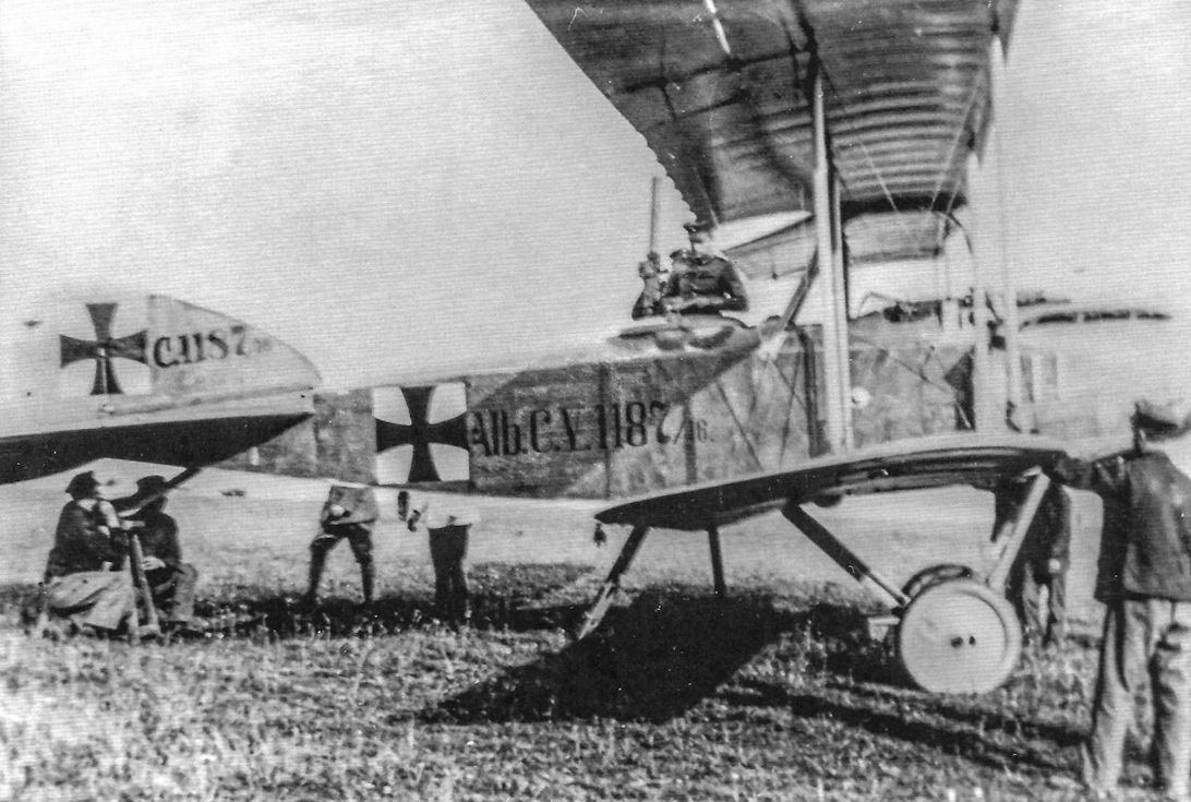
Albatros C.V/16 C.1187/16 being readied for another mission. (Peter M. Grosz Collection/STDB)
-

J.Herris - Albatros Aircraft of WWI. Volume 2: Late Two-Seaters /Centennial Perspective/ (25)
Albatros C.V/16 1187/16.
-

J.Herris - Albatros Aircraft of WWI. Volume 2: Late Two-Seaters /Centennial Perspective/ (25)
Albatros C.V/16 C.1187/16 of FliegerAbteilung (A) 217 with a second, unidentified C.V/16 in the background. (Courtesy Bruno Schmaling)
-

J.Herris - Albatros Aircraft of WWI. Volume 2: Late Two-Seaters /Centennial Perspective/ (25)
Albatros C.V/16 C.1189/16 at rest. (Peter M. Grosz Collection/STDB)
The unusual Mercedes D IV straight-8 engine was quickly developed from the D III 6-cylinder as an interim measure pending availability of the D IVa 6-cylinder. The D IV was subject to failure in twin-engine bombers but was successful in the Albatros C.V (shown) and LVG C.IV reconnaissance aircraft, where its geared propeller gave it excellent efficiency and it could be fully cowled, reducing drag. These types were as fast as Allied fighters when they reached the front, allowing them to avoid interception. -

J.Herris - Albatros Aircraft of WWI. Volume 2: Late Two-Seaters /Centennial Perspective/ (25)
Oblt. Behrla of FA 44 in Albatros C.V/16 1211/16 highlights the damage the fuselage could withstand. On 24 May 1917 Behrla and Vzfw. Rosengart were flying this aircraft at 4,500 meters when Rosengart put the C.V into a spin upon seeing enemy fighters. After a drop of 400 meters, Rosengart leveled the C.V and Behrla stood up when the C.V hit turbulence and Behrla found himself floating three meters above the aircraft! Behrla then fell onto the fuselage, creating the hole illustrated. Although Behrla could not climb back into his cockpit, Rosengart still landed the C.V safely. (Peter M. Bowers Collection/The Museum of Flight)
-
J.Herris - Albatros Aircraft of WWI. Volume 2: Late Two-Seaters /Centennial Perspective/ (25)
Feld-Flieger Abteilung 25 lineup has an Aviatik C.III in the left foreground with Albatros C.V/16 1212/16 in the center background. The wet, muddy airfield conditions were harsh on both men and machines.
Другие самолёты на фотографии: Aviatik C.III - Германия - 1916
-

J.Herris - Albatros Aircraft of WWI. Volume 2: Late Two-Seaters /Centennial Perspective/ (25)
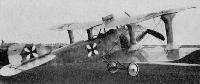
Wearing his Pour le Merite, Albert Dossenbach stands in front of his heavily-armed Albatros C.V/16.
-

J.Herris - Albatros Aircraft of WWI. Volume 2: Late Two-Seaters /Centennial Perspective/ (25)
Albert Dossenbach, wearing his Pour le Merits, stands in front of his Albatros C.V/16. Dossenbach was an aggressive pilot and modified his C.V to carry a synchronized Vickers machine gun in addition to the standard synchronized Spandau mounted on the right side. The pointed spinner is also non-standard. The massive propeller used by the C.V/16 is prominent.
-

J.Herris - Albatros Aircraft of WWI. Volume 2: Late Two-Seaters /Centennial Perspective/ (25)
Albert Dossenbach, wearing his Pour le Merits, stands in front of his Albatros C.V/16 C.1220/16.
-

J.Herris - Albatros Aircraft of WWI. Volume 2: Late Two-Seaters /Centennial Perspective/ (25)
"Franz und Emil" pose with their mount, Albatros C.V/16 C.1257/16, in the field. Of all the Albatros two-seater designs, the C.V was the only one that offered clearly superior performance in addition to robust practicality.
-

J.Herris - Albatros Aircraft of WWI. Volume 2: Late Two-Seaters /Centennial Perspective/ (25)
Albatros C.V/17 C.1371/17 marked with the arrow insignia of FliegerAbteilung 7. It is tactical '6' of that unit. (Peter M. Grosz Collection/STDB)
-

J.Herris - Albatros Aircraft of WWI. Volume 2: Late Two-Seaters /Centennial Perspective/ (25)
This Albatros C.V/16 has an interesting white/dark/white band around the engine cowling. The aircraft was assigned to FliegerAbteilung (A) 288. Unfortunately, the name on the nose is not legible. (Courtesy Bruno Schmaling)
-

J.Herris - Albatros Aircraft of WWI. Volume 2: Late Two-Seaters /Centennial Perspective/ (25)
Albatros C.V/16 awaits its next mission.
-

J.Herris - Albatros Aircraft of WWI. Volume 2: Late Two-Seaters /Centennial Perspective/ (25)
Crew of an Albatros C.V/16 assigned to FliegerAbteilung (A) 217 prepares for a mission. (Courtesy Bruno Schmaling)
-

J.Herris - Albatros Aircraft of WWI. Volume 2: Late Two-Seaters /Centennial Perspective/ (25)
Anonymous C.V/16 with black and white 'X' marking. The canvas propeller cover is being removed in preparation for flight. (Peter M. Grosz Collection/STDB)
-

J.Herris - Albatros Aircraft of WWI. Volume 2: Late Two-Seaters /Centennial Perspective/ (25)
The crew gets this unidentified Albatros C.V/16 ready for another reconnaissance sortie. Two dark bands are painted around the fuselage but no serial number is visible. The plywood semi-monocoque fuselage shows up well.
-

A.Imrie - German Bombers /Arms & Armour/
First London night bomber. Flying an aircraft of this type (Albatros C V), Offizierstellvertreter Klimke and his observer. Oberleutnant Leon, from Flieger Abteilung 19 based on Handzaeme aerodrome in Belgium, undertook a voluntary attack on the capital during the night of 6/7 May 1917, dropping five 12.5kg P.u.W. bombs which fell in a line from Hackney to Holloway. Despite their offensive spirit, a severe reprimand was forthcoming, since Kagohl III was being readied for just such work at this time, and it was considered that the Klimke/Leon action had unnecessarily alerted the British defences to such a possibility. They were transferred to Kagohl III and took part in several raids against Britain flying the unwieldy Gotha G IV, which was, as Klimke later said 'not as much fun as our own effort!'
-

J.Herris - Albatros Aircraft of WWI. Volume 2: Late Two-Seaters /Centennial Perspective/ (25)
The streamlined Albatros C.V/16 was the first of the second generation Albatros C-types. The eight-cylinder Mercedes was completely enclosed by the cowling, the key C.V recognition feature. The tail surfaces and fuselage strongly resembled contemporary Albatros fighters. Bruno Loerzer (in sweater) stands in front of this C.V/16(OAW) of Kampfstaffel Metz; Hptm. Schmickaly is in the front cockpit.
-

J.Herris - Albatros Aircraft of WWI. Volume 2: Late Two-Seaters /Centennial Perspective/ (25)
Bruno Loerzer (in sweater, back to camera) stands in front of this C.V/16(OAW) of Kampfstaffel Metz; Hptm. Schmickaly is in the front cockpit. The Albatros C.V/16 was an excellent aircraft for its time and was faster than opposing Allied fighters when it reached the front. Subsequent Albatros two-seater designs did not approach its level of success.
-

J.Herris - Albatros Aircraft of WWI. Volume 2: Late Two-Seaters /Centennial Perspective/ (25)
This C.V/16(OAW) appears to be the same aircraft; the apparent difference in fuselage color is likely due to the different angle of the photograph.
-

J.Herris - Albatros Aircraft of WWI. Volume 2: Late Two-Seaters /Centennial Perspective/ (25)
This Albatros C.V/16 looks tired; the finish is warn and repaired and there are bullet holes in the tail that have not been repaired. A circular device, probably a mirror, is suspended from the upper wing in front of the pilot. A light tactical number '5' was applied over a dark background on the rear fuselage turtledeck. (Peter M. Grosz Collection/STDB)
-

J.Herris - Albatros Aircraft of WWI. Volume 2: Late Two-Seaters /Centennial Perspective/ (25)
Airmen of an unknown unit photographed with an unidentified Albatros C.V/16. The elevator control cable was carefully streamlined with a fitting when exiting the rear fuselage. (Courtesy Bruno Schmaling)
-

J.Herris - Albatros Aircraft of WWI. Volume 2: Late Two-Seaters /Centennial Perspective/ (25)
"Franz und Emil" pose with their Albatros C.V/16. One cowling panel has been removed and the fixed gun, claw brake, and general finish are well shown. (Courtesy Reinhard Zankl)
-

J.Herris - Albatros Aircraft of WWI. Volume 2: Late Two-Seaters /Centennial Perspective/ (25)
This Albatros C.V/16 served at Cappy bei Amiens in France. The national insignia on the vertical tail was painted over an octagonal white background, a feature thought to be associated with OAW-built aircraft.
-

J.Herris - Albatros Aircraft of WWI. Volume 2: Late Two-Seaters /Centennial Perspective/ (25)
Albatros C.V/16 of FliegerAbteilung 6b with a black and white unit marking but no visible serial number. (Courtesy Bruno Schmaling)
-

J.Herris - Albatros Aircraft of WWI. Volume 2: Late Two-Seaters /Centennial Perspective/ (25)
Two views of an Albatros C.V/16 of Bavarian FliegerAbteilung 2. It appears to carry a checkerboard marking in front of the national insignia.
-

J.Herris - Albatros Aircraft of WWI. Volume 2: Late Two-Seaters /Centennial Perspective/ (25)
Albatros C.V assigned to Feld-Flieger Abteilung 23. Hptm. Hermann Palmer, the unit's commanding officer, is facing the camera.
-

J.Herris - Albatros Aircraft of WWI. Volume 2: Late Two-Seaters /Centennial Perspective/ (25)
"Franz und Emil" bundled up for flight in front of their Albatros C.V/16 of Bavarian FliegerAbteilung 2.
-

J.Herris - Albatros Aircraft of WWI. Volume 2: Late Two-Seaters /Centennial Perspective/ (25)
An Albatros C.V/16 of FliegerAbteilung (A) 261 to which unit mechanics have fitted a captured Vickers machine gun and synchronized it to fire through the propeller arc. The aircraft, flown by Vzfw. Fritz Kosmahl, has a dark (black?) band around the nose; the small cross in circle indicates where it was hit by enemy fire. (Peter M. Grosz Collection/STDB)
-

J.Herris - Albatros Aircraft of WWI. Volume 2: Late Two-Seaters /Centennial Perspective/ (25)
Portrait of a pilot and his Albatros C.V/16.
-

J.Herris - Albatros Aircraft of WWI. Volume 2: Late Two-Seaters /Centennial Perspective/ (25)
Scenes of Feld FliegerAbteilung 3b and a well-maintained Albatros C.V/16 assigned to the unit. In the group photo the early Axial logo is visible on both propeller blades. This unit was later re-designated Flieger Abteilung 46b and flew both the Albatros C.X and the Albatros C.XII. (Courtesy Bruno Schmaling)
-

-

J.Herris - Albatros Aircraft of WWI. Volume 2: Late Two-Seaters /Centennial Perspective/ (25)
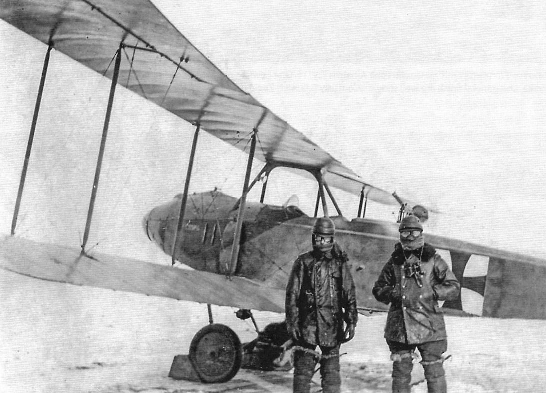
Albatros C.V/16 ready to take off on another mission in the winter of 1916/1917.
-
J.Herris - Albatros Aircraft of WWI. Volume 3: Bombers, Seaplanes, J-types /Centennial Perspective/ (26)
The sole Albatros G.II prototype under test at Johannisthal. An Albatros C.V is in the background. (Peter M. Grosz Collection/SDTB)
Другие самолёты на фотографии: Albatros G.II/G.III - Германия - 1916
-
J.Herris - LVG Aircraft of WWI. Volume 2: Types C.II-C.V /Centennial Perspective/ (35)
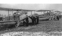
German two-seater units often had a variety of different aircraft types for different missions, and FAA 292b's aircraft line up is shown here. From left to right the aircraft are AEG C.IV, Roland C.II, LVG C.IV, another Roland C.II, a DFW C.V, and an Albatros C.V. This photo was taken at the same time as the other FAA 292b photos above. (Bruno Schmaling)
Другие самолёты на фотографии: AEG C.IV/C.IVA/C.V/C.VI - Германия - 1916DFW C.V - Германия - 1916LFG Roland C.II - Германия - 1915LVG C.IV - Германия - 1916
-

J.Herris - Halberstadt Aircraft of WWI. Volume 2: CL.IV-CLS.I & Fighters /Centennial Perspective/ (45)
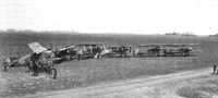
Three Halberstadt D.III fighters are at the far end of this lineup at Grand Metz, ready for action. In this case, it is training action. At left is an Albatros C.III with an Albatros C.V second from left and two Fokker Eindeckers in the middle. (Peter M. Grosz Collection/STDB)
Другие самолёты на фотографии: Albatros C.III - Германия - 1916Fokker E.I / E.II / E.III / M.14 - Германия - 1914Halberstadt D.II/D.III - Германия - 1916
-

J.Herris - Albatros Aircraft of WWI. Volume 2: Late Two-Seaters /Centennial Perspective/ (25)
Unlike most German two-seater units that had a wide variety of types, Flieger Abteilung 2 appears fully equipped with Albatros C.V/16 reconnaissance planes.
-

J.Herris - Albatros Aircraft of WWI. Volume 2: Late Two-Seaters /Centennial Perspective/ (25)
Albatros C.V/16 of Flieger Abteilung 2.
-

J.Herris - Albatros Aircraft of WWI. Volume 2: Late Two-Seaters /Centennial Perspective/ (25)
Details of 220 hp Mercedes D.IV number 25412 in an unidentified Albatros C.V/16.
-

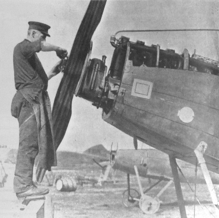
Jane's All The World Aircraft 1919 /Jane's/
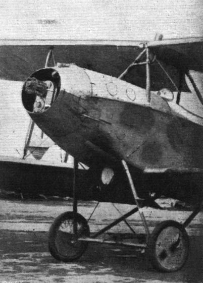
A nose-piece of an Albatros with 8-cylinder 250 h.p. Mercedes engine, and geared-down airscrew.
-

M.Dusing - German & Austro-Hungarian Aero Engines of WWI. Vol.2 /Centennial Perspective/ (65)
Mercedes D IV installed in an Albatros C.V.
-

J.Herris - Albatros Aircraft of WWI. Volume 2: Late Two-Seaters /Centennial Perspective/ (25)
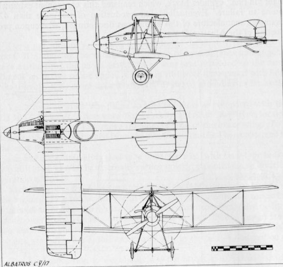
Albatros C.V/17 1371/17 shows its refined airframe with airfoil radiator in place of the ear radiators of the C.V/16. The header tank above the engine on the C.V/16 is no longer needed, so the exhaust and fixed Spandau are the only blemishes on the streamlined engine cowling. The upper surfaces of the wings are painted in the three-color camouflage scheme used by later C.V and C.VII aircraft. The fuselage appears to be stained in a dark color and the arrow insignia of FliegerAbteilung 7 is just barely visible against the dark fuselage color. The typical signal flare cartridges are mounted alongside the observer's cockpit. (Peter M. Grosz Collection/STDB)
-

J.Herris - Albatros Aircraft of WWI. Volume 2: Late Two-Seaters /Centennial Perspective/ (25)
Albatros C.V/17 C.1380/17 has experienced a rough landing and the lower wings were damaged as well as the landing gear.
-

J.Herris - Albatros Aircraft of WWI. Volume 2: Late Two-Seaters /Centennial Perspective/ (25)
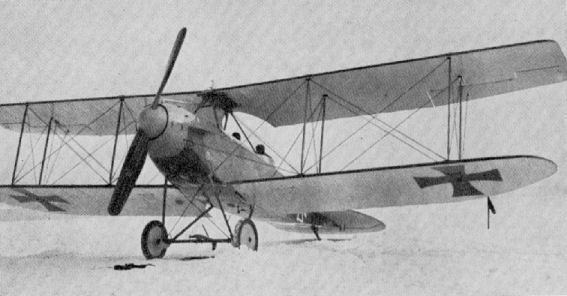
Albatros C.V/17 photographed on the snow-covered Johannisthal airfield during the winter of 1916/1917. Elimination of the ear radiators in this batch improved its streamlining. (Peter M. Bowers Collection/The Museum of Flight)
-

O.Thetford, P.Gray - German Aircraft of the First World War /Putnam/
Albatros C V/17, with curved lower wing and balanced control surfaces.
-

J.Herris - Albatros Aircraft of WWI. Volume 2: Late Two-Seaters /Centennial Perspective/ (25)
"Franz und Emil" pose in front of their Albatros C.V/17. Axial made the propeller as indicated by the decal.
-

J.Herris - Albatros Aircraft of WWI. Volume 1: Early Two-Seaters /Centennial Perspective/ (24)
A snowy celebration; an Albatros C.V/17 is decorated as the 2,500th aircraft built by Albatros.
-

-
Журнал - Flight за 1918 г.
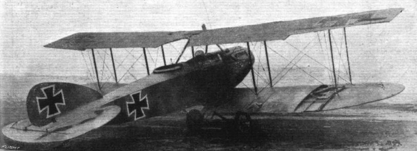
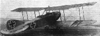
Three-quarter rear view of the Albatros biplane.
-

Журнал - Flight за 1918 г.
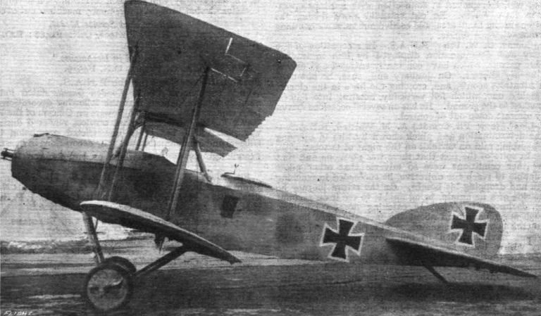
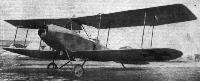
Side view of the Albatros biplane.
-

-
Журнал - Flight за 1918 г.
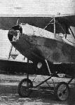
Three-quarter front view of the Albatros biplane.
-
Журнал - Flight за 1918 г.
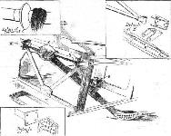
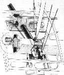
THE ALBATROS C.V-TYPE BIPLANE. - The chassis and engine, showing the gearing to the tractor screw.
-

-

J.Herris - Albatros Aircraft of WWI. Volume 2: Late Two-Seaters /Centennial Perspective/ (25)
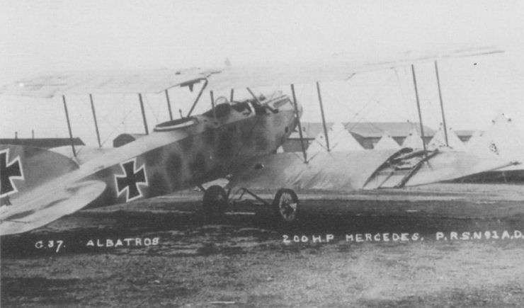
Albatros C.V/17 1394/17 of FliegerAbteilung 18 showing the unusual camouflage applied to the upper surfaces. This aircraft was shot down on 12 May 1917 by 45 Squadron, RFC and assigned G.37 as its captured German aircraft number. It was extensively examined by the British and the engineering analysis was published by Flight in 1918. It featured a three-color camouflage scheme that may have been unique to this aircraft.
-
Журнал - Flight за 1918 г.
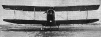
Front view of the Albatros biplane.
-

-
Журнал - Flight за 1918 г.
Rear view of the Albatros biplane.
-

M.Dusing - German Aviation Industry in WWI. Volume 1 /Centennial Perspective/ (84)
Alb. C.V/17; airfoil radiator, rounded lower wingtips.
During its takeoff an Albatros C.V/17 of FliegerAbteilung 2 displays its elegant streamlining. -

J.Herris - Albatros Aircraft of WWI. Volume 2: Late Two-Seaters /Centennial Perspective/ (25)
An Albatros C.V/17 in flight reveals its graceful lines.
-

J.Herris - Albatros Aircraft of WWI. Volume 2: Late Two-Seaters /Centennial Perspective/ (25)
Albatros C.V/17 C.1420/17 was photographed in November 1917 while testing a 2cm Becker cannon installation. Unusually, the pilot was relocated to the rear cockpit and the Becker cannon was also located there, no doubt making for cramped quarters. The Becker was located on the left side of the cockpit and mounted to fire downward and forward. The magazine was loaded from the front cockpit, which was also unusual, as was the bomb sight at right in the aft cockpit. Two triggers on the control wheel fire the Becker and the fixed pilot's machine gun.
-

-

-

J.Herris - Albatros Aircraft of WWI. Volume 2: Late Two-Seaters /Centennial Perspective/ (25)
This experimental C.V was likely one of the three prototypes. The I-struts reduced drag; however, they also obstructed the crew's field of view somewhat and that made them unpopular. Moreover, the stress calculations for the I-struts were still only approximate and the engineers were reluctant to proceed with them.This aircraft also had the ear radiators installed with a louvered panel to reduce drag, a feature that was not used in production. The observer's gun run has not yet been installed and an external gravity tank was fitted above the upper wing.
-

-
O.Thetford, P.Gray - German Aircraft of the First World War /Putnam/
Albatros C V Experimental
-

J.Herris - Albatros Aircraft of WWI. Volume 2: Late Two-Seaters /Centennial Perspective/ (25)
This Albatros C.V/16 of Feld-Flieger Abteilung 270Lb has suffered a bad landing. It carries an interesting marking in front of the national insignia and displays under-fuselage details.
-
Журнал - Flight за 1918 г.
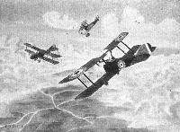
CORNERED. - An Albatros C5 caught by a couple of British machines.
-
Журнал - Flight за 1918 г.
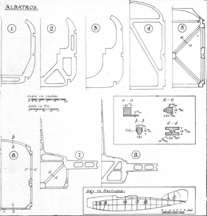
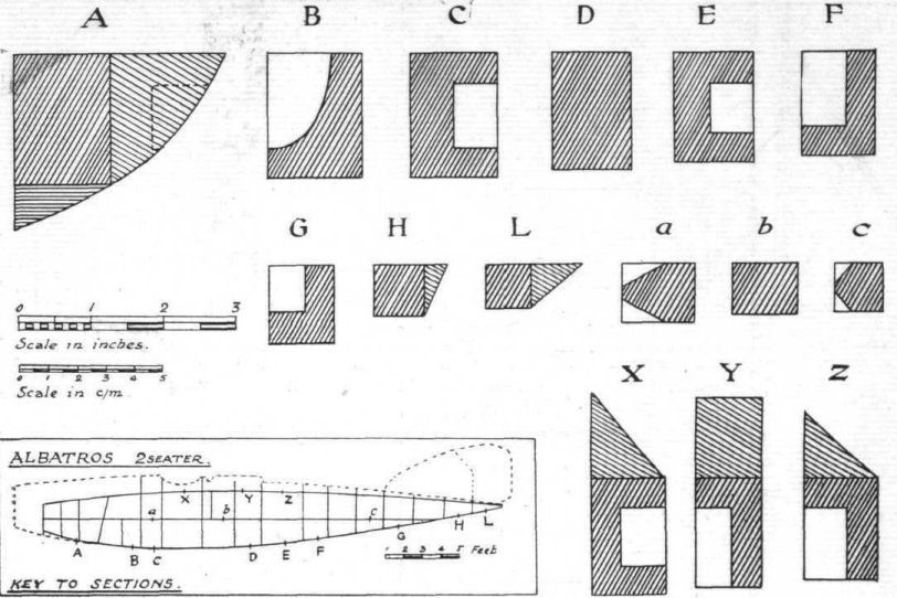
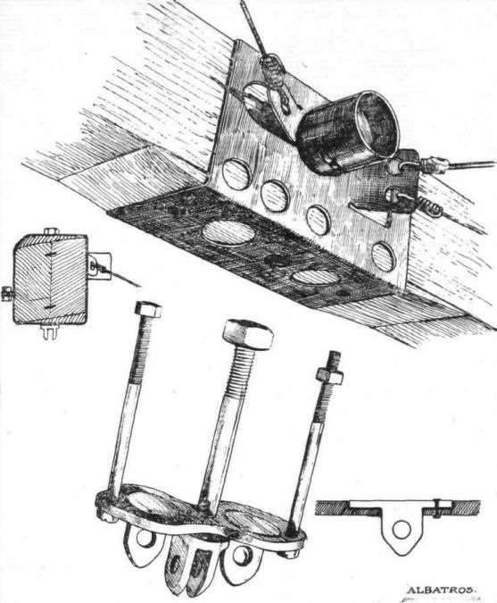
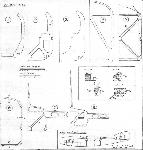
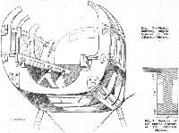
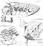
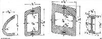
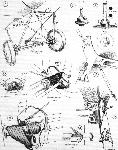
Fig. 1. - Half sections of some of the more important bulkheads of the Albatros fighting biplane. Inset, dimensions of some of the members.
-
Журнал - Flight за 1918 г.
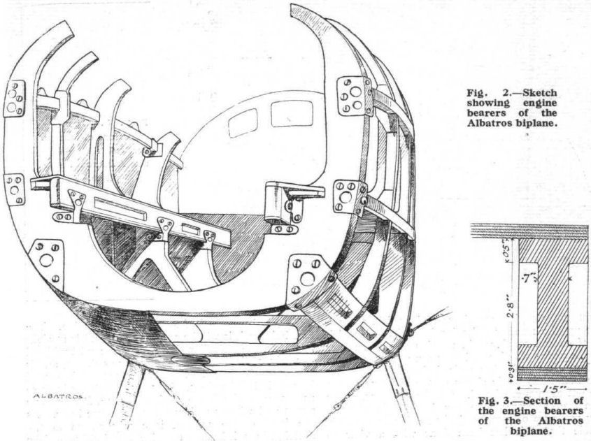
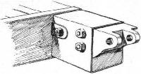
Fig. 2. - Sketch showing engine bearers of the Albatros biplane.
Fig. 3. - Section of the engine bearers of the Albatros biplane. -

Журнал - Flight за 1918 г.
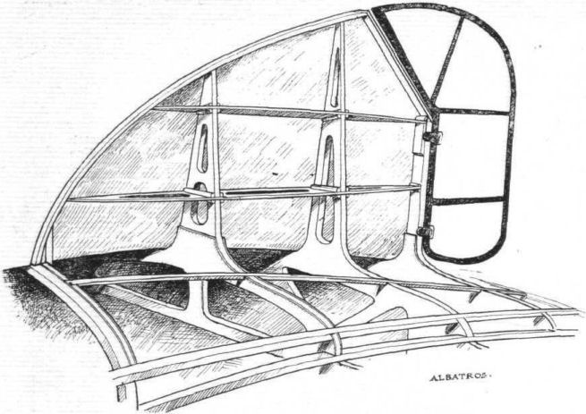
Fig. 4. - Construction of the vertical fin on the Albatros biplane.
-
Журнал - Flight за 1918 г.
Fig. 5. - The tail skid and its attachment on the Albatros biplane. Inset, upper right-hand corner, details of the skid pivot. Upper left-hand corner, the collar which prevents the rubber cord from slipping along the tube. These collars are apparently made up of two stampings - bowl-shaped - welded together along their peripheries. In the bottom left-hand corner is shown the bracket attaching the cross tube to the ply-wood bulkhead.
-
Журнал - Flight за 1918 г.
Fig. 6. - Sections and dimensions of the longerons of the Albatros biplane.
-
Журнал - Flight за 1918 г.
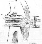
Fig. 7. - Sketch showing turnbuttons securing engine cowl to upper longerons. The bulkhead is prevented from shifting by a wood screw going through the longeron into the bulkhead.
-
Журнал - Flight за 1918 г.
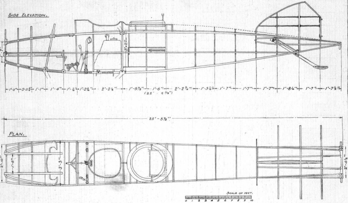
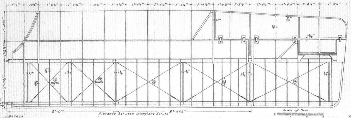
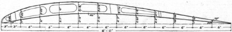
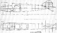
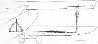
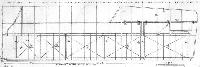
Fig. 8. - General arrangement of the Albatros body. Side elevation and plan to scale.
-
Журнал - Flight за 1918 г.
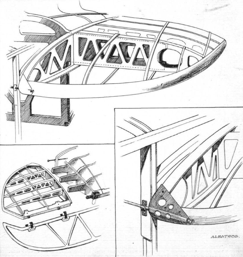
Fig. 9. - Sketches of the tail plane and its attachments on the Albatros biplane.
-
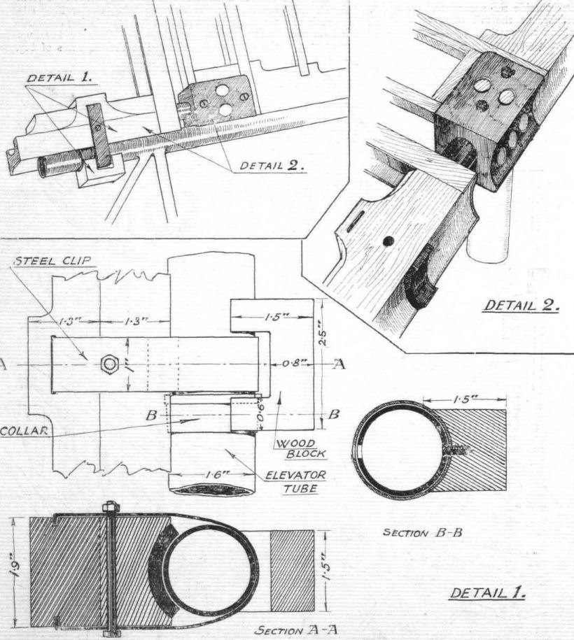
Журнал - Flight за 1918 г.
Fig. 10. - Details of the tail plane and elevator attachment on the Albatros biplane. In the upper left hand corner a view from above of the fuselage stern post, the tail plane trailing edge, and the elevator tube. In the upper right hand corner is shown the attachment of the trailing edge to the fuselage. Bottom: details of the steel clip bearings for the elevator tube; also the wood block to which the elevator fabric is attached around the hinge. The attachment of this wood block must be attended with some difficulty, as the wood screw and screw driver have to be inserted through a hole in the opposite wall of the steel tube. Probably a special tool is employed.
-
Журнал - Flight за 1918 г.
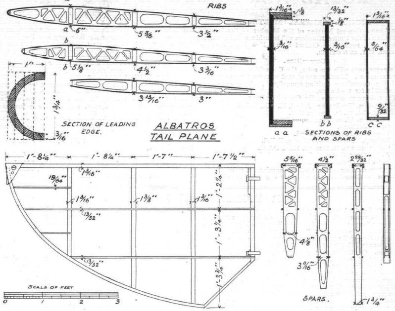
Fig. 11. - General arrangement and dimensions of the members of the tail plane on the Albatros biplane.
-
Журнал - Flight за 1918 г.
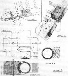
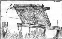
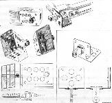
Fig. 12. - The main petrol tank of the Albatros biplane. The pilot's seat is placed in the recess, and is prevented from sliding about by the steel clips shown. On the right is shown a section of the tank, with the internal bracing rods and baffle plates. The insets show the brackets supporting the tank, and the arrangement for tightening the straps that hold the tank.
-
Журнал - Flight за 1918 г.
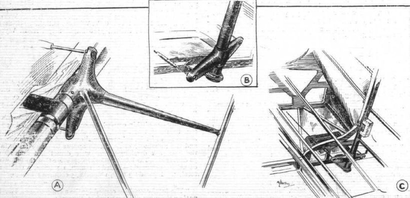
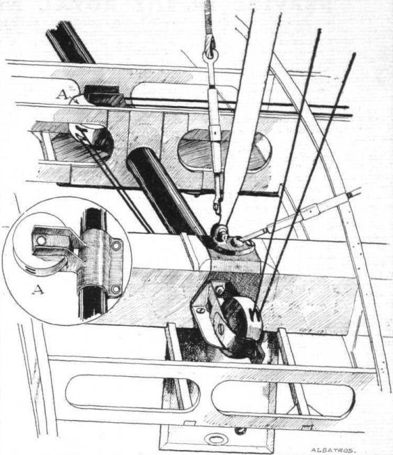
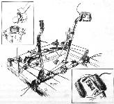
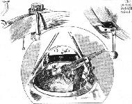
Fig. 13. - The controls of the Albatros biplane. Insets show the ball and socket joint for the control lever locking arrangement, and the hand grip with the gun trigger on the main control lever.
-

Журнал - Flight за 1918 г.
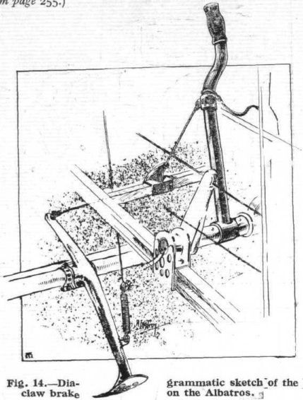
Fig. 14. - Diagrammatic sketch of the claw brake on the Albatros.
-

Журнал - Flight за 1918 г.
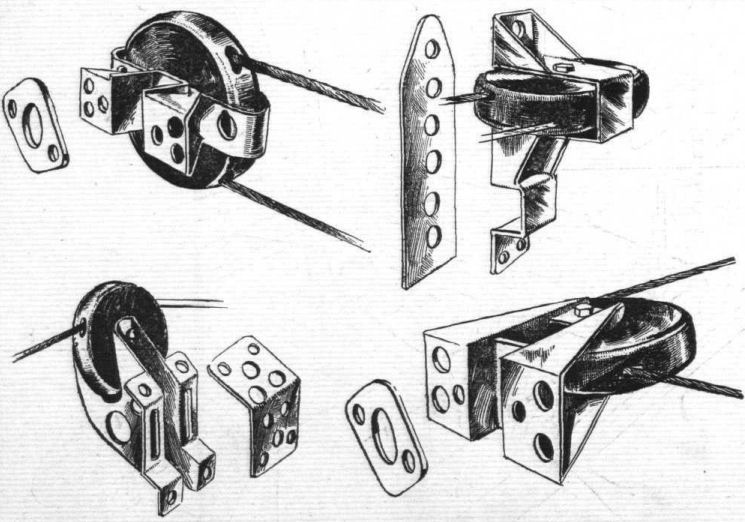
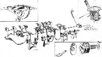
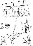
Fig. 15. - The brackets supporting the pulleys over which pass the control cables are of a somewhat complicated nature. In the top left-hand corner is shown the pulley over which the elevator cable passes after leaving the crank lever on the rocking shaft (see Fig. 13). The pulley in the top right-hand corner is bolted to the middle longeron just ahead of the tail plane, and serves to guide the elevator cable. In the bottom left-hand corner is shown the pulley mounted on the top longeron in front of the tail plane, over which passes the elevator control cable, and the pulley shown in the bottom right-hand corner guides the rudder cable in front of the foot bar, where its direction changes from a lateral to a longitudinal one.
-
Журнал - Flight за 1918 г.
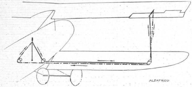
Fig. 16. - Diagram of the aileron control system of the Albatros.
-
Журнал - Flight за 1918 г.
Fig. 17. - The elevator and rudder crank levers on the Albatros biplane. A shows the elevator crank lever with its ball and socket joint for the turnbuckle. In C is shown the mounting of the rudder, and in B the bottom rudder bracket and crank lever.
-
Журнал - Flight за 1918 г.
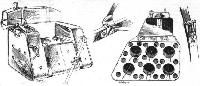
Fig. 18. - The machine gun and its mounting on the Albatros Fighter. The bag for the spent cartridges should be noted. When not in use the butt of the gun rests in the clip shown. The two insets show the locking devices for the gun pivot and gun ring respectively.
-
Журнал - Flight за 1918 г.
Fig. 19. - So as to be out of the way when the gunner is firing from a standing position, the seat on the Albatros Fighter is hinged and sprung as shown in this sketch.
-
Журнал - Flight за 1918 г.
Fig. 20. - Details of the bomb gear on the Albatros biplane.
-
Журнал - Flight за 1918 г.
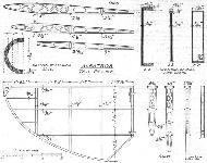
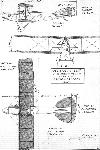
Fig. 21. - General arrangement of the upper left-hand wing of the Albatros biplane, to scale.
-

Журнал - Flight за 1918 г.
Fig. 22. - Sheet steer spar box and socket for compression tube of the upper plane of the Albatros biplane. The bottom sketch shows the attachment of the terminals for the interplane cables and struts.
-
Журнал - Flight за 1918 г.
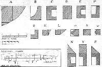
Fig. 23. - Sections, to scale, of the leading edge, main spars, and false spar of the Albatros biplane.
-

Журнал - Flight за 1918 г.
Fig. 24. - The wing section of the Albatros biplane.
-
Журнал - Flight за 1918 г.
Fig. 25. - The spar box and its attachment to the fuselage of the Albatros fighting biplane.
-
Журнал - Flight за 1918 г.
Fig. 26. - The wing flap and some wing details of the Albatros fighting biplane.
-

Журнал - Flight за 1918 г.
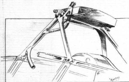
Fig. 27. - The cabane supporting the radiator and upper plane of the Albatros biplane. Note the manner of carrying the water tube through one of the cabane legs.
-
Журнал - Flight за 1918 г.
Fig. 28. - Sketch showing lugs on root of upper main wing spars of the Albatros.
-
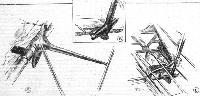
Журнал - Flight за 1918 г.
Fig. 29. - Some details of the undercarriage of the Albatros. 1. General arrangement of the undercarriage. 2 and 3. Detail of cable terminal. 4. Steel strip passing under body, to which is welded the front chassis strut socket. 5. Attachment of rear chassis strut to body. 6. Lower attachment of chassis struts and shock absorbers. 7, 8, and 9. Details of same.
-
Журнал - Flight за 1918 г.
Fig. 30. - Arrangement of wing flap control cable pulleys in bottom wing of the Albatros. After passing over pulleys on rear spar, the control cables pass through the spar horizontally.
-

Журнал - Flight за 1917 г.
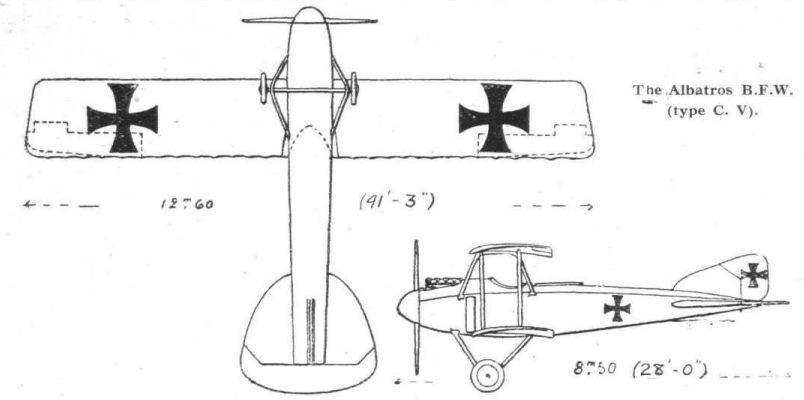
The Albatros B.F.W. (type C. V).
-

Jane's All The World Aircraft 1919 /Jane's/
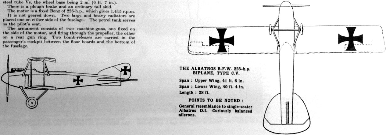
The Albatros B.F.W. 225-h.p. biplane, type C.V.
-

-

-
Журнал - Flight за 1918 г.
THE ALBATROS BIPLANE. - Plan, front and side elevation to scale.
В.Кондратьев Самолеты первой мировой войны
АЛЬБАТРОС C-V / ALBATROS C-V
В 1915 году Эрнст Хейнкель перешел на фирму Ганза-Бранденбург. Дальнейшие разработки фирмы Альбатрос велись под руководством инженеров Шуберта и Телена. В начале 1916-го они спроектировали разведчик "Альбатрос" C-V, в целом аналогичный ранним аэропланам Хейнкеля.
Основные отличия состояли в более мощном моторе и улучшенной аэродинамике. Установлен капот обтекаемой формы и округлый кок винта. Самолет выпускался серийно, но из-за не вполне надежного двигателя он не получил широкого распространения.
К концу года машину слегка модернизировали, снабдив руль высоты и элероны роговой аэродинамической компенсацией. Штурвал пилота заменили ручкой управления. Усовершенствованный аппарат получил обозначение C-V/17. Максимальное одновременное количество C-V во фронтовых эскадрах никогда не превышало 65 экземпляров.
ДВИГАТЕЛЬ
"Мерседес"D.IV, 220 л.с. (C-V).
ВООРУЖЕНИЕ
Стрелковое: 1 х 7,92-мм синхронный пулемет "Шпандау" 08/15 и 1 х 7,92-мм турельный пулемет "Парабеллум"
ЛЕТНО-ТЕХНИЧЕСКИЕ ХАРАКТЕРИСТИКИ
C-V
Размах, м 12,6
Длина, м 8,9
Площадь крыла, кв.м 43,4
Сухой вес, кг 1069
Взлетный вес, кг 1585
Скорость максимальная, км/ч 170
Время набора высоты, м/мин 1000/8
Потолок, м 4800
Описание: