A.Jackson British Civil Aircraft since 1919 vol.1 (Putnam)
CENTRAL CENTAUR 2A (Open model)
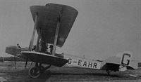
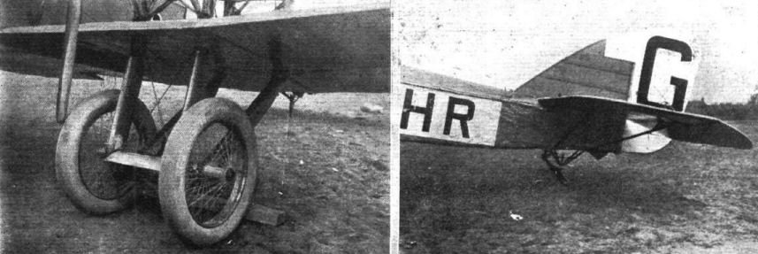
Three-bay biplane seating two pilots and six passengers in open cockpits, powered by two 160-h.p. Beardmore engines, designed by J. S. Fletcher and built by the Central Aircraft Company at Kilburn 1919. One aircraft only: K-170 G-EAHR, c/n 101, first flown 7.19 by F. T. Courtney. Destroyed in crash following take-off with crossed elevator cables, Northolt 7.20. Span, 63 ft. 8 in. Length, 39 ft. 3 in. Tare wt., 4,996 lb. A.U.W., 7,250 lb. Max. speed, 90 m.p.h. Cruise, 65 m.p.h.
CENTRAL CENTAUR 2A (Cabin model)
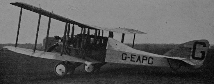
Improved version with cabin for seven passengers, built at Kilburn 1920. One aircraft only: G-EAPC, c/n 102, first flown at Northolt by F. T. Courtney 5.20, C. of A. issued 30.6.20. Took part in Air Ministry commercial aeroplane competition, Martlesham 8.20, won no award, but achieved a speed range of 89-48 m.p.h. Spun in with the loss of six lives, including that of the pilot, Lt. F. P. Goodwin-Castleman, at Sharvel Lane, Hayes, Middlesex, 25.9.20. Specification similar to open model.
Показать полностью
Журнал Flight
Flight, March 6, 1919.
PEACE TIME AEROPLANES
<...>
The third model to which reference has been made is a twin-engine machine, designed as a passenger carrier seating eight passengers. This machine is of very pleasing appearance, and the engine power being comparatively low, two Beardmore engines of 160 h.p. each, should not prove excessively expensive to run. The cabin will have non-splintering windows of Triplex glass, and will be electrically heated, thus providing for the comfort of the passengers. If desired, the machine can be used for carrying half a ton of goods or mails instead of the passengers. With three hours' fuel on board the speed range is expected to be 40 to 90 m.p.h. This machine is now in course of construction.
The Central Aircraft Co. will be pleased to give further information relating to delivery and prices of their various types upon application to their offices at 179, High Road, Kilburn. We might add that there is one more type coming through, of which we are not, however, permitted to give any particulars at present, but it is hoped to prove the last word in performance. This machine may be expected to go through its trials in the coming spring.
Flight, September 25, 1919.
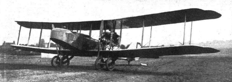
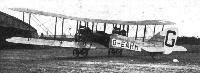
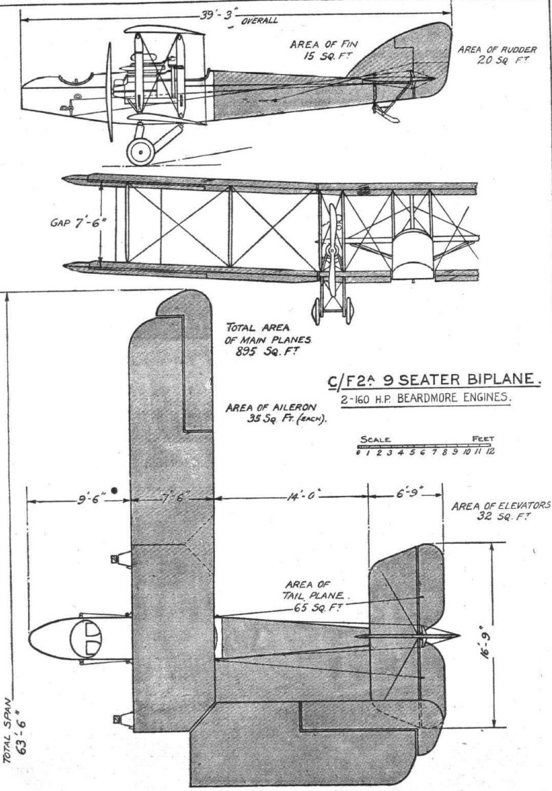
THE CENTRAL AIRCRAFT CO.'S 9-SEATER BIPLANE
Two 160-h.p. Beardmore Engines
IN our issue of March 6, 1919, we referred briefly to a twin-engined passenger carrier which the Central Aircraft Co., Ltd., of 179, High Road, Kilburn, then had in contemplation. This machine is now an accomplished fact, having passed her initial tests at the Northolt aerodrome of this firm. In the issue referred to an illustration was published showing the machine as she would appear in flight. A comparison between this illustration and the photographs and drawings published herewith will show that some minor alterations from the original design have been made. Thus it was originally intended to enclose the engines and to place the radiators in the nose of the engine nacelles. As actually built, the radiators are placed behind the engines, which at present are left uncovered. Another respect in which the actual machine differs from the original design is in the matter of passenger accommodation. The intention was to provide a cabin for the passengers, while the pilots were to be in an ordinary open cockpit. In the first machine built, however, the cabin has been omitted, the passengers sitting in two open cockpits. There are two ways of designing an aeroplane - as there are of doing many other things - one, is to design the machine as an aeroplane first and to add the desired amount of refinement afterwards. This is the plan followed by Mr. "Tony" Fletcher, chief designer of the Central Aircraft Co. The other is to design the upholstery first and then to build the machine around it.
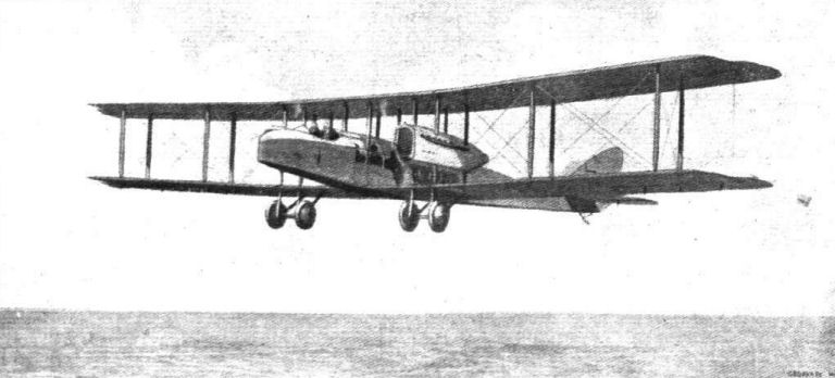
By keeping everything simple the initial expense of the first experimental machine - and in spite of our considerable knowledge of the subject, experimental machines are not yet entirely superfluous - is kept down to a reasonable figure, while quite as much can be learned from such a simplified aeroplane as from the highly-finished article. Having then by experiment and experience discovered the aerodynamic and structural qualities, it is time enough to commence thinking about the upholstery. This is, we believe, approximately the reasoning which has led the Central Aircraft Co. to keep their first twin-engined machine as simple as possible, and as the accompanying illustration will testify, the procedure has by no means spoilt the lines, which, as a matter of fact, are very pleasing to the eye. Bearing in mind, then, that the machine is an experimental one, and judging it from this point of view, we may proced to an examination of its various features.
Generally speaking, the C/F 2A, which is the series number of the machine, is an ordinary fuselage biplane with the engines placed on the wings. In general arrangement standard practice is followed, and the machine is, in fact, a straightforward, commonsense production, designed to be built at reasonable cost, and of sturdy construction to withstand hard wear. If there is anything unusual about the design it is mainly a matter of aerodynamic efficiency, which will allow a good load to be carried with a reasonably low engine power - 320 h.p. to carry nine people, including the pilot, at 90 m.p.h. - must be considered fairly good economy as aeroplane transport goes.
The fuselage is constructed, as regards its front portion, of four longerons cross-braced with X struts of wood and covered with three-ply wood. The rear part, from the cockpit to the stern, also has four longerons, but is cross-braced by vertical and horizontal struts and bracing wire. The two top longerons run straight through, forming an excellent datum line for trueing up the fuselage. The three-ply covering of the front part of the body is extremely neatly done, especially the nose. A trap door in the floor of the fuselage gives access to the back of the instrument board, while the pilots' cockpit is reached via steps mounted on a tube suspended from the body. When the machine is in flight these steps are drawn up, the tube lying along the bottom with the steps projecting through slots in the floor. The two pilots are seated side by side and dual controls are provided. The rudder controls are in the form of foot bars, while elevator and aileron controls are by wheel mounted on a tubular column. All the usual instruments are fitted.
Immediately behind the pilots' cockpit, separated from it by a bulkhead, is the petrol tank, which has a capacity of about 50 gallons, or sufficient for a flight of two hours at full throttle or two and a-half to three hours when flying throttled down. The oil tanks are mounted above the engines on the inter-plane engine struts.
Behind the petrol tank are the passengers' cockpits, or, rather, there is one cockpit divided by a horizontal strut in the top of the body. The front part of this cockpit accommodates four passengers, each sitting in a corner, so that two face forward and two face aft. The rear portion of the cockpit seats three passengers, two facing forward and one facing aft. Just at present the seats are not over-comfortable, but it should be pointed out that the arrangement is a temporary one, and that when a cabin is fitted the seating arrangements will be given further consideration.
The main planes, which consist of straight centre sections and end sections -set at a dihedral angle of 4 deg., have a span of 63 ft. 6 ins. and a chord and gap of 7 ft. 6 ins. There is no stagger. As already mentioned, the engines - 160 h.p. Beardmore's are mounted between the planes. The ash engine bearers are carried on stout transverse beams resting in slots in the inter-plane engine struts. The whole structure is well cross-braced and gives an impression of great strength. It was originally intended to have the engines cowled in and to place the radiators in the nose of the engine nacelles, but the present machine has the radiators placed between the rear pair of engine struts, and no cowling is fitted. Cowls may still be fitted if desired, as the exhaust collectors could be passed out through the openings left for this purpose in the radiators. In that case louvres in the cowls would have to be provided. Two instruments are fitted direct on the engine bearers and are placed at a slight angle, so as to be more easily seen from the pilots' cockpit. These are revolution indicators and radiator thermometers. The petrol leads, as well as the engine controls, pass out to the engines from the fuselage through fairings.
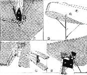
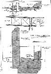
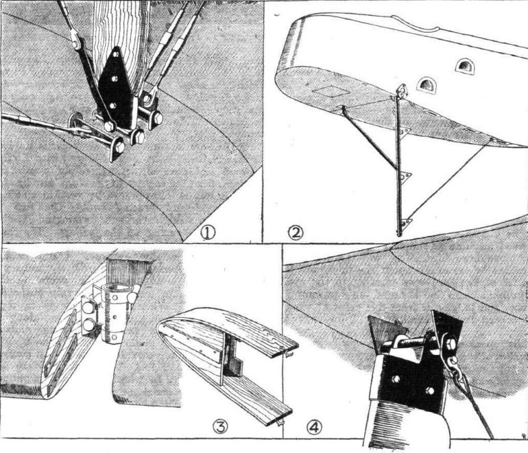
As the machine is of somewhat large span the wings are made to fold back, in which position the overall width of the machine is reduced to about 27 ft. The hinge joints in the wings are of a simple but substantial type, as shown in one of the accompanying sketches. The space in front of the front spar joints is covered by an easily removable false portion of the leading edge, as shown in the sketch. All the inter-plane struts are of spruce, streamline, of course, and the wing bracing is in the form of stranded cables, duplicated in the case of the lift cables and single for the anti-lift cables. The attachment of these cables and of the pin-jointed interplane struts is shown in one of our sketches. Ailerons are fitted to both upper and lower planes, and in order not to upset the aileron control cables when the wings are folded, these are passed from the body to a pulley on the rear spar hinge, which forms the pivot for folding the plane, and hence outward and forward again to a pulley on the front spar, from which the cable passes to the aileron crank lever. The elevator cables are placed outside the fuselage, while the rudder control cables pass inside the body, where they are protected, in the space occupied by the passengers, by aluminium casings.
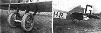
The tail planes are of conventional type and do not call for any comment except to point out that the symmetrical tail plane is mounted on four brackets and is adjustable, although not during flight. The tail skid is mounted externally on a pyramid of steel tubes.
Each of the two undercarriages consists of two vees of wood, attached to the lower wing spars immediately under the engines. The following is the specification of the Central Aircraft Co.'s nine-seater :- Span, 63 ft. 6 ins. (with wings folded, 27 ft.); length o.a., 39 ft. 3 ins.; height, 12 ft. 6 ins.; weight empty, 3,850 lbs.; weight fully loaded, 5,850 lbs.; weight/sq. ft., 6.6 lbs; weight/h.p., 16-7 lbs.; engines, two Beardmore, 160 h.p. each; petrol consumption about 25 galls, per hour; oil consumption, 2 galls, per hour; speed range, 40-90 m.p.h.; duration, 2-3 hours.
Показать полностью