A.Jackson British Civil Aircraft since 1919 vol.1 (Putnam)
B.A.T. F.K. 26
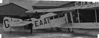
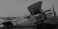
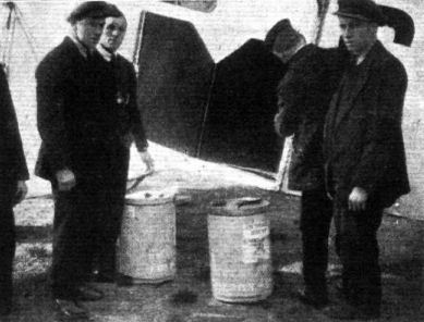
The unnamed F.K.26, designed by Frederick Koolhoven and built by the British Aerial Transport Co. Ltd., was the first purely civil transport aeroplane built after the First World War and the designs are said to have been put in hand on Armistice Day 1918. It was of orthodox appearance and construction, with a wooden, fabric covered airframe, two bay wings and a single Rolls-Royce Eagle VIII water-cooled engine. Four passengers were carried in a glazed cabin 8 ft. long and the pilot sat in an open cockpit in the rear fuselage. The prototype K-102/G-EAAI was built at Hythe Road, Willesden, flown at Hendon in April 1919 and later used experimentally on the Hounslow-Paris route. Probably the most discussed detail of the new aircraft was the placing of the pilot’s cockpit aft of the cabin, and Koolhoven’s intention was, it is said, to give the pilot a good chance of surviving a crash, as he was the only occupant likely to give an intelligent account of it. The second aircraft, K-167/G-EAHN, was flown to the First Air Traffic Exhibition at Amsterdam in July 1919 by Christopher Draper. A third, G-EANI, appeared in the October, was exhibited at the Olympia Aero Show as the 'B.A.T. Commercial Mk. I’ in July 1920, and during the rest of the summer was used for passenger flights at Hendon in place of ’HN, which had crashed. The reduction in Lord Waring’s aviation interests forced the closure of the B.A.T. concern, and G-EAPK, built in November 1919, was the firm’s last product. It was sold to S. Instone and Co. Ltd. in August 1920, and went to Croydon for continental charter work and scheduled services to Paris.
When the British Aerial Transport Co. Ltd. closed down, Koolhoven returned to Holland, and a number of machines, including the F.K.26S G-EAAI and ’NI, were sold to Ogilvie Aircraft. They were stored in the Company’s works at 437 High Road, Willesden, for many years, during which their markings were obliterated. In April 1937 Koolhoven purchased ’Al for £300 and shipped it to Holland, where it was erected and exhibited without markings at that year’s Netherlands Aero Show.
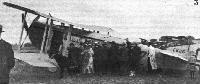
With the removal of Ogilvie Aircraft to Primrose Garages, Watford, the one remaining specimen found a new last resting-place. This irreplaceable historical aircraft was unfortunately demolished during the Second World War, when a contractor’s lorry backed into it, thereby depriving the nation of what would today have been a valuable museum piece.
SPECIFICATION
Manufacturers: The British Aerial Transport Co. Ltd., Willesden, London, N.W. Power Plant: One 350-h.p. Rolls-Royce Eagle VIII.
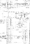
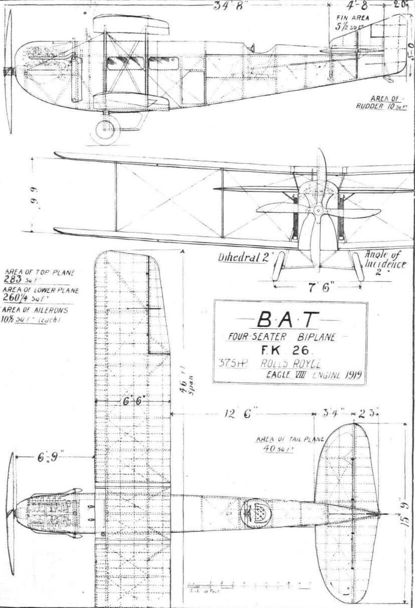
Dimensions: Span, 46 ft. Length, 34 ft. 8 in. Height, 11 ft. 3 in.
Weights: All-up weight, 4,500 lb.
Performance: Maximum speed, 122 m.p.h. Initial climb, 1,000 ft./min. Ceiling, 8,000 ft. Range, 600 miles.
Показать полностью
Журнал Flight
Flight, April 17, 1919.
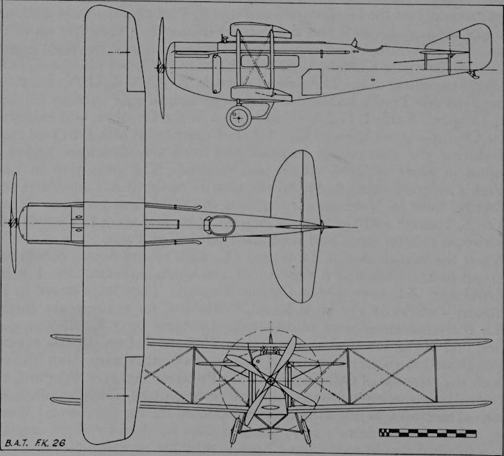
THE B.A.T. FOUR-SEATER BIPLANE
ONE of the first, if not the first, post-War "commercial" aeroplanes has just been completed by the British Aerial Transport Co., Ltd., at their works at Willesden. By postwar commercial aeroplane, we mean a machine that has been designed since the Armistice, specially for commercial work - either passenger, mail or goods - and not a war machine converted for this purpose. In this particular case, the B.A.T. F.K. 26 has been designed either for passenger work or for carrying mails, there being accommodation for four passengers, besides the pilot in the former case, whilst for the latter purpose it is merely a question of adapting the passenger cabin to meet the requirements for this kind of work. Mr. Frederick Koolhoven, the designer of this machine, is to be congratulated on having succeeded in producing a machine that is original in many respects, but is at the same time of absolutely straightforward design, free from "cranky" features.
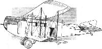
F.K. 26 is a single-engined tractor biplane, and as may be seen from the accompanying scale drawings, the general lay-out of the "weight items" is efficient and well thought out. The position of the pilot, well aft of the main planes, is such that it enables him to have an excellent view in all directions.
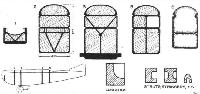
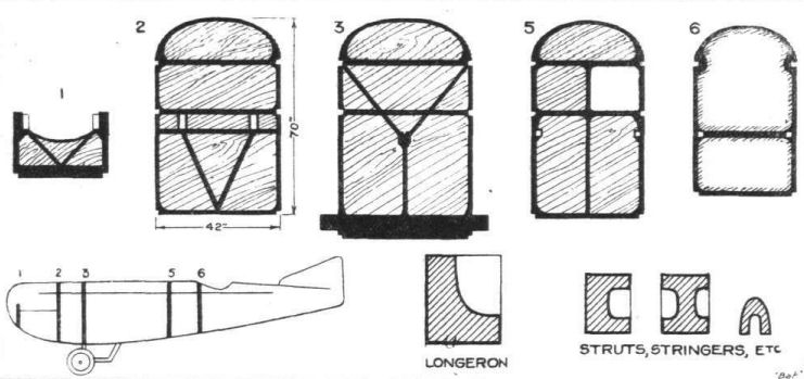
The fuselage, which is 30 ft. 10 in. in length, is of rectangular section, very deep near the wings and tapering to a vertical knife-edge at the rear. Two different forms of construction are employed in the fuselage, the front half, from the nose to the end of the passenger cabin, being built up of three-ply and formers in a similar manner to that obtaining in the German Albatross machines, whilst the rear half is of the conventional girder construction. Both systems, however, have many interesting features. There are four main longerons, of about 1 1/2 by 1 1/4 in. L-section (solid where necessary), running from end to end, and one additional longeron of similar section in the front half situated between the upper and lower longerons on each side, level with the line of thrust. These longerons are of ash in front and spruce in rear portions. In all there are five transverse formers in the front half of the fuselage, built up mainly of H-section members reinforced by three-ply, and varying in shape and structure as shown in one of the accompanying diagrams. There are also diagonal H-section struts between each former, on t he sides of the fuselage, and an outer covering of three-ply tacked to the formers and struts completes the construction. There is no wire bracing whatever in this portion of the fuselage. The first and second formers carry the strong ash engine bearers, the third and fourth are placed in line with the front and rear wing spars respectively - the fourth former being in the centre of the passenger's cabin is, therefore, left open, i.e., it has no cross members except at the top and bottom. The fifth former serves as the end wall of the cabin, and between this and the fourth former is what might be termed a false former of light construction. The engine and fuel compartments have a single outer covering of three-ply, whilst the cabin portion has a double (inner and outer) covering. Three separate compartments or bulkheads are thus formed, the first being the "engine room," the second housing the large fuel tanks (six hours), and the third the passenger's cabin.
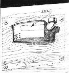
The latter is exceptionally roomy, measuring roughly, 3 ft. in width, 8 ft. in length, and just over 5 ft. in height. For passenger work, therefore, it affords great possibilities in the way of a luxuriously fitted-up and comfortable "saloon," with armchairs, tables, etc. In the present model there will be three armchairs and one folding seat, the latter being opposite the door, which is at the rear of the cabin on the port side. Windows, with sliding Triplex glass, are cut in the sides of the cabin between the top and middle longerons, three on the starboard, and two on the port sides, whilst portholes will also be let into the turtledeck roof at various points.
The cabin is equally suitable for mail work, and one can easily visualise this roomy compartment fitted up with pigeon-holes and benches, with a P.O. clerk busy at work sorting out letters, depositing them in their respective parachute bags, and dropping them overboard above their destination!
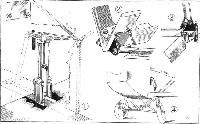
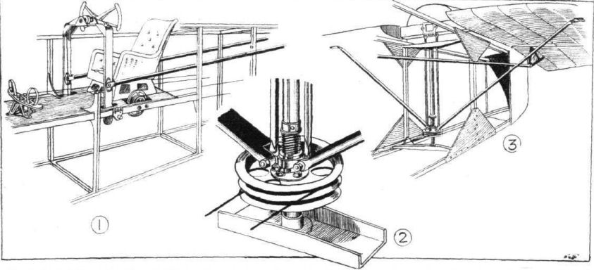
Aft of the cabin the fuselage is a girder of six bays, the first set of cress members being built up on the fines of the formers in the front half, as shown by No. 6 in the accompanying diagram. The other cross members are of the usual H-section, reinforced here and there by three-ply. With the exception of the last one, all the bays are braced with flat "streamfine" steel cable; the last bay, however, has H-section diagonal struts and a three-ply covering. The pilot and control are located in the second bay, being supported fairly high up in the fuselage by two channel-section bearers on a three-ply floor. This rear portion of the fuselage is covered with fabric, except for the. top, which has a three-ply turtledeck. At the end of the third bay a steel tube passes across the fuselage through the lower ends of the vertical struts and projects a few inches on either side of the fuselage, thus providing a means for lifting the tail.
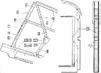
The control is similar to the well-known "Dep." type, and consists of a wooden n-bridge pivoted to the previously mentioned bearers, carrying at its upper end the peculiar shaped "wheel" shown in one of the accompanying sketches. The elevators are operated positively by flat elliptical-section steel tubes, anchored at the forward ends to each side member of the bridge and connected at the rear to a strong single crank arm on the underside of each elevator flap. The aileron cables are led from the "wheel" over pulleys down the arms of the bridge to its base, whence they pass down to pulleys a t the end of the cabin, just below the floor, under which they proceed to pulleys at a point just behind the front spar, where they are taken at right angles out of the fuselage through the lower plane to pulleys just beyond the outer interplane struts. From here they pass out underneath the plane to cranks on the underside of the ailerons. The upper and lower ailerons are connected by steel cables, and the upper port and starboard ailerons are connected by a balance cable passing along inside the top plane. The rudder is operated direct by cables from a wooden foot-bar reinforced by sheet aluminium. Except for the aileron and rudder cables, all other control connections (engine, etc.), are steel or aluminium tubing - all shafts or cranks being mounted in ball bearings. The engine control rods (aluminium) pass out from the cockpit through the turtle deck and pass along on top of the latter to the "engine room." The switches are mounted outside the cockpit on the port side of the turtle-deck.
The angle of incidence of the tail plane can be adjusted whilst in flight by means of an aluminium wheel, at the pilot's left just below the seat, which operates through cables a screw and nut gear as shown in one of the accompanying sketches. The rear spar of the tail plane is hinged, so that the front of the tail is raised or lowered.
The main planes are of equal span, and are made of four interchangeable sections and a centre section to which the upper planes are attached. The centre section is mounted on two pairs of steel struts sloping outwards from formers three and four. Each pair of struts is laterally cross-braced by flat, oval section steel wires. A steel strip also connects the lower ends of the port and starboard struts and takes some of the load from the landing wires which are taken from the base of the centre section struts to the lower plane. The lower plane is attached to short centre sections projecting from the sides of the fuselage, giving the same overall width as the top centre section. The centre section spars pass through the fuselage and are built integral with the respective former. In the front one the ends are cut short for the passage of the chassis strut, which passes through a welded steel box which replaces the cut away portion of the spar. The end of this box also forms the wing attachment fitting which is the same on all spars, and which is shown in one of the illustrations. Constructionally, the planes present nothing unusual, except, perhaps, in the tips. They have what might be described as a lateral washout, that is, the under surface curves up to meet the top surface which is level right to the tip. The spars of laminated I-section, solid where necessary, and the ribs are built up as usual of spruce webs and flanges. Each wing has four bays, the compression members being of the box type, and located at the interplane struts with a third in between. The internal bracing is of piano wire, the outer bay having a diagonal strut. Top and bottom planes are separated by two pairs of tubular steel s:ruts aside, and the whole of the external bracing is by streamline wire. Ailerons are fitted to both top and bottom planes, and these taper from root to tip.
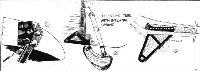
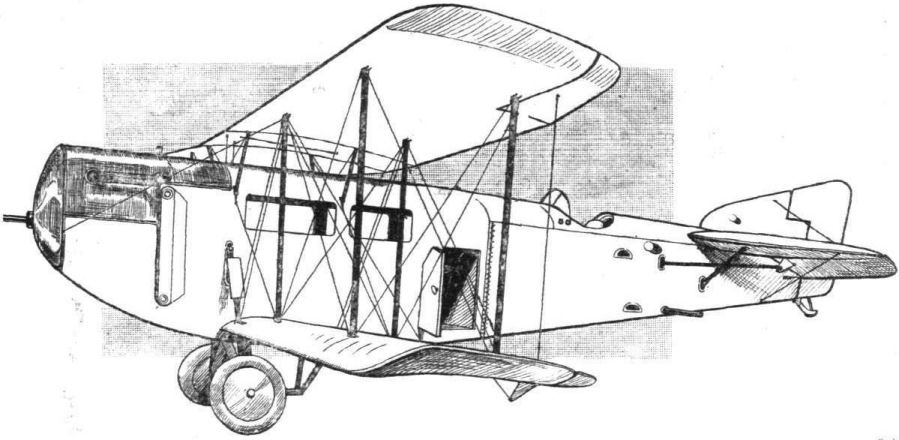
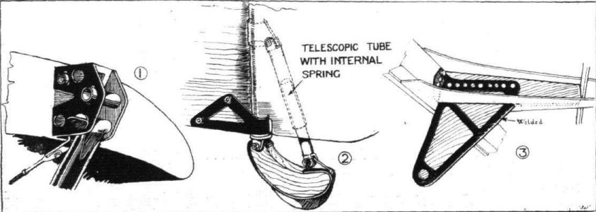
The tail plane is of high aspect ratio, and has a symmetrical streamline section. It is built in one piece and mounted just above the top longerons. The rudder is balanced, the vertical fin being cut away to receive the balanced portion. By far and away the most interesting feature of the F.K 26 is the landing chassis and its shock-absorbing arrangement. As may be seen from our illustrations, the wheels are each hinged by two stub axles to a cabane, consisting of a pair of V struts connected by a longitudinal member, mounted on the bottom of the fuselage. The front pair of these stub axles lies at right angles to longitudinal axis of the machine, and the other pair is inclined back to the rear V of the cabane. Extending upwards from each outer extremity of this "axle-Vee" is a steel tube which is connected at its upper extremity to the end of a lever projecting through the sides of the fuselage and hinged at its other end to the centre of the fuselage-former. Near the outer extremity of this lever is a lug from which connection is made to an oleo shock-absorber and to a pair of ordinary elastic shock-absorbers. There is a similar gear on each side of the fuselage. Thus, on landing, as the wheels rise, they also lift the levers against the action, first, of the oleo, and then of the elastic absorbers. The levers above referred to are of welded steel box construction, and it will be noticed that the wheels are splayed, so that when in flight they point inwards in a down direction, and when on the point of landing they are more or less horizontal, and when the machine is at rest, with its full weight on the wheels, they point inwards in an up direction. The general arrangement and construction of this landing gear is clearly shown in our illustrations.
Another interesting feature is in the tail skid. This is of the steerable type, and consists of a short steel-shod wooden skid anchored at its upper end to a tube passing up through, and secured to, the rudder post. The "head" of the skid is connected to a lug some distance up the rudder post by two telescopic tubes passing up through the rudder, and containing a steel spring, which absorbs the shocks on striking the ground.
The engine is a Rolls-Royce Eagle VIII, mounted, as previously stated, on two strong ash bearers between the first and second formers. It is enclosed by an aluminium bonnet, whilst a "manhole" in the bottom of the fuselage gives access to the engine from underneath.
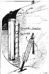
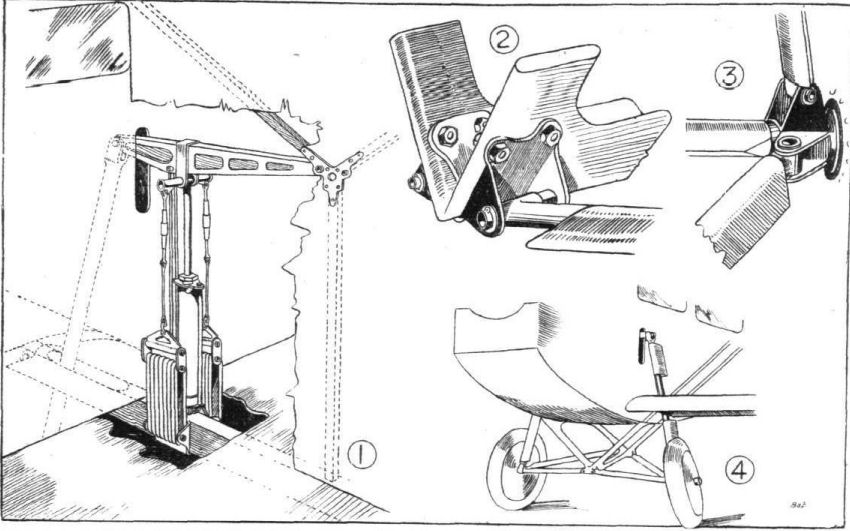
The cooling system is very efficiently carried out, and is made up of two long streamline-shaped "honeycomb" radiators, mounted, one on each side of the fuselage. They are connected top and bottom to two tanks within the fuselage, as indicated in one of the accompanying sketches. On the back of each radiator is a shutter, which can be opened or closed from the pilot's cockpit. A neat and simple oil-cooling radiator is also fitted; this is shown in one of our sketches, and consists of an extension of the oil tank next to the engine projecting through the starboard side of the fuselage, and having a series of tubes passing through it from front to rear. This projection also carries the oil filter and filling-cup. As previously mentioned, the fuel tanks are located in the compartment between the engine and the cabin. Petrol is delivered direct from the main tank to the carburettor through the agency of two windmill pumps mounted above the turtle deck and the tanks. There is, however, a small service tank, for emergency, let into the leading edge of the top centre section.
The estimated maximum speed of the B.A.T. F.K. 26 is 110 m.p.h., whilst the landing speed is about 40 m.p.h.
Показать полностью