A.Jackson British Civil Aircraft since 1919 vol.2 (Putnam)
GRAHAME-WHITE G.W.E.7
Luxury transport with folding wings designed by M. Boudot to seat four passengers in the cabin in the nose and the pilot in a glazed compartment between the centre section struts. One aircraft only, G-EALR, c/n G.W.E.7, powered by two 320 h.p. Rolls-Royce Eagle V, built at Hendon by The Grahame-White Aviation Co. Ltd. 8.19, damaged beyond repair in forced landing in 1919, burned 1920. Span, 60 ft. 0 in. Length 309 ft. 0 in. Tare wt., 5,785 lb, A.U.W.,.7,047 lb, Max. speed, 116 m.p.h. Cruise, 104 m.p.h.
Показать полностью
Журнал Flight
Flight, September 11, 1919.
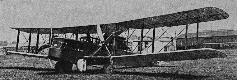
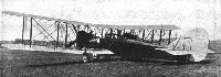
THE GRAHAME-WHITE "AERO-LIMOUSINE"
WHAT may be described as the first item on the post-War programme of the Grahame-White Co. has made its appearance, and looks like making a success of the future before it. We refer to the "Aero-Limousine," which has just successfully emerged from its initial trials at Hendon, and which is illustrated and described herewith.
Although in general design and construction it presents nothing of a startling nature, a close inspection reveals a careful consideration of every detail that makes for efficient and thorough design. The ultimate use to which this machine is to be put has been borne in mind in the design of each detail throughout. It has been the aim of the designer, M. Boudot, to produce in this machine the safety, combined with the comfort, of the passengers, and reliability rather than mere performance, and the question of weight has not been allowed to predominate over strength, utility and comfort.
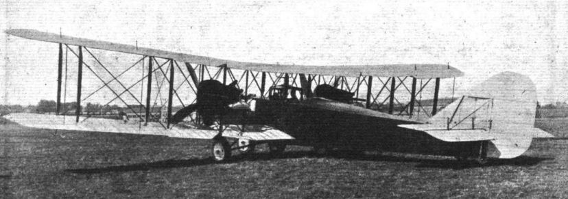
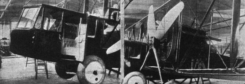
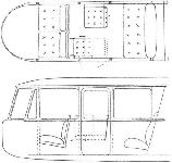
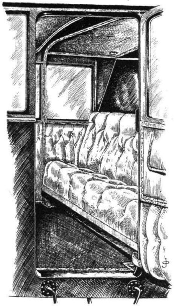
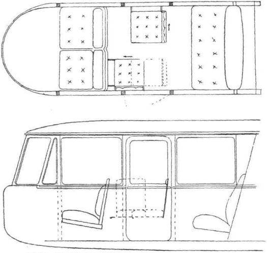
The "Aero-Limousine" is a fuselage biplane fitted with two engines, one mounted between the upper and lower planes on each side of the fuselage, driving direct four-bladed tractor screws. The passenger's cabin, which is in the extreme nose of the fuselage, is, so far, the most comfortable and luxuriously fitted one we have seen. It is apparent that the Grahame-White Co.'s experience in motor car body work - which, by the way, has been one of the firm's "side-lines" for some time back - has come in useful. The whole cabin, in fact, is exactly similar to a first-class motor-car body, even to the outside finish. In this first model provision is made for four passengers, seated in pairs tandem fashion, the left-hand front seat being hinged so as to swing back and give access to the front seats. In future models, however, it is proposed to lengthen the cabin and provide two additional tip-up seats giving a seating accommodation for six passengers on the lines indicated by one of the accompanying drawings. The whole of the interior of the cabin is upholstered in a neat grey Bedford cord, whilst large Triplex windows, extending completely round the sides and front of the cabin, give plenty of light and afford an excellent view in every direction. A large door on the port side of the cabin - well clear of the tractor screw - and a strong foot-step allow of easy access. There is an adjustable ventilator in the nose of the cabin, and two air-outlets in the rear of the roof for ventilation, whilst the temperature can be regulated by means of an electrically heated carpet. Communication can be made with the pilot by means of a speaking tube, and an air speed indicator and altimeter are fitted in front of the cabin.
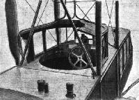
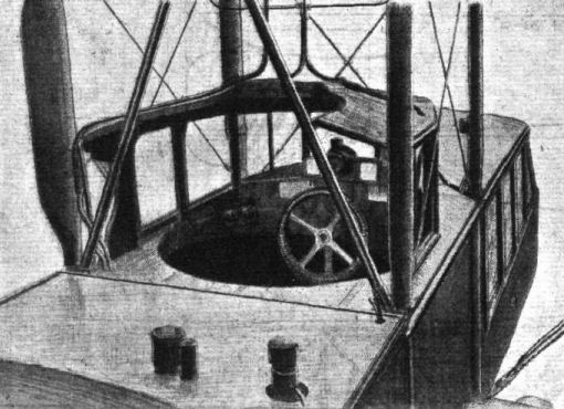
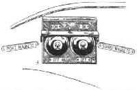
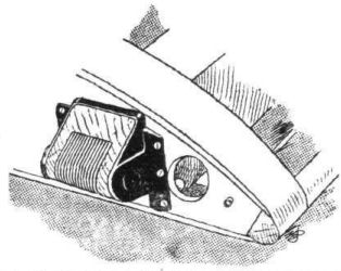
The pilot's cockpit is situated at the rear of and immediately above the cabin. It is exceptionally roomy and comfortable, and ample protection is provided by means of a sort of conning tower. The view, too, from the pilot's cockpit is quite good. All the instruments are neatly disposed around the cockpit, and the engine and petrol controls are located on the right and left-hand sides respectively. The engine switches, which can be operated either separately or simultaneously, are mounted slightly forward on the left-hand side of the pilot.
The control is of the wheel and rudder bar type, the arrangement of the rudder bar being most noteworthy. In this the bar is mounted below the cockpit floor, in which are cut two slots having their edges reinforced on the top by steel plates. Working in these slots, and sliding on the plates, are the foot pedals, which are connected to the rudder bar by a spindle extending below each and working in a slot in the rudder bar. The rudder bar is of wood reinforced by steel plates with lightening holes. On the left of the pilot's seat is a hand-wheel operating the tail plane incidence gear, which is of the usual nut and worm type.
In construction the fuselage follows more or less standard practice, the rear portion aft of the cabin being of wire-braced girder construction with square section longerons and channel-section struts, the last bay being braced laterally by three-ply. The fore portion of the fuselage is built up on hoop-formers of ash reinforced with three-ply, thus giving a "straight-through" construction with no wire cross-bracing. Where the formers are exposed to view inside the cabin, they are covered with a thin veneer of mahogany, which, when polished, gives a neat finish to the decoration of the cabin. The outer covering is three-ply and fabric for the cabin, and doped fabric for the rear portion. The fabric covering is "laced" on the under side by means of a novel quick-fastening arrangement sometimes used for fastening raincoats, overalls, dresses, etc., an arrangement that can only be described as consisting of a length of "tape" which on being pulled along the edges of the covering - to which it is connected - joins the latter together.
The main planes are of standard construction, and are built up in seven sections, comprising a centre section of about 20 ft. span and two outer sections for the top plane, and a similar arrangement for the lower plane, except that the centre section is divided into two by the fuselage. The outer sections are hinged at the roots of the rear spars so as to fold back, thus facilitating housing, the overall width folded being 28 ft. The tubular compression members are all of the same diameter, but vary in gauge according to the stresses imposed. The same fittings are thus employed in each case. Both upper and lower outer sections are given a dihedral angle of 4 degrees, but have neither stagger nor sweepback. The interplane struts are steel tubes with built-up wood fairings giving a deep streamline shape. External bracing is by cable, streamlined by wood fairings. Unbalanced ailerons are fitted to both upper and lower planes.
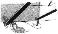
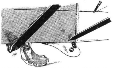
The tail plane, which is rectangular in plan form, is of symmetrical streamline section, and, as previously mentioned, its angle of incidence can be varied during flight. The elevators are unbalanced and divided, whilst the rudder, which is of ample proportions, is balanced. A large vertical fin is mounted above the fuselage. All the tail surfaces are of standard construction, and are braced by cable and steel struts, which are streamlined. The tail skid is very neat and well throughout, as may be seen by one of the accompanying sketches.
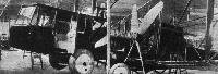
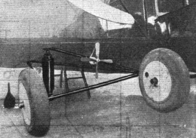
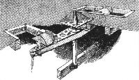
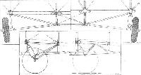
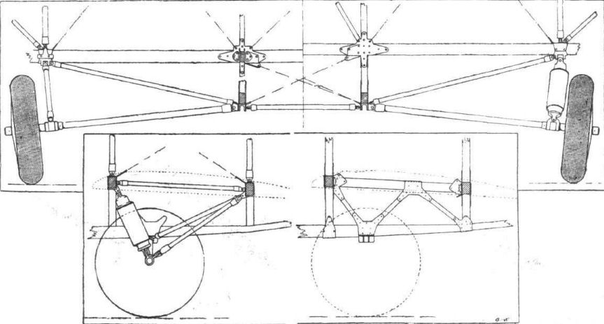
An exceptionally strong and efficient landing chassis is fitted, the general arrangement of which is clearly shown in the illustrations. It consists of two separate units, the main landing gear, and what may be termed an emergency gear. The latter, which comes into action only to prevent the machine from tipping on her nose, and to take the weight of the machine should the main chassis fail, consists of two large wheels rigidly mounted on the fuselage, slightly in advance of the main wheels.
The two wheels of the main landing gear are situated under the engines, and are connected to the main plane and fuselage by a neat and very effective triangular system of tubular members. The shock-absorbing device is incorporated into the front strut of the vee, and consists of a set of steel springs combined with an oil dashpot.
The power unit consists of two Rolls-Royce Eagle Mark V engines, of 320 h.p., mounted one on each side of the fuselage between the top and bottom planes. They are carried in strong tubular steel mountings, with the radiators in front. The total horse-power available is well above that required to fly the machine, so that it is possible to fly comfortably at three-quarter throttle, thus considerably increasing the life of the engines, to say nothing of making tor reliability. The engines can be started either by means of a starting handle, mounted on the rear of each engine, or else by way of a magneto-starter from the cockpit.
It is worthy of note that all the petrol has been stored as far away as possible from the engine and passengers, in order to reduce the risk of fire to a minimum. The main tank is located immediately behind the pilot's cockpit, whilst the gravity tanks are mounted in the centre section of the top plane. The petrol supply is maintained by two windmill pumps mounted in the slipstream of each tractor screw just below the lower plane centre section. There is also an auxiliary pump operated from the cockpit.
The following is the general specification and performance of the G.-W. "Aero-Limousine" :-
Span 60 ft.
Chord 6 ft. 7 ins.
Gap 6 ft. 5 1/2 ins.
Dihedral 4# top and bottom wings.
Overall length 39 ft.
Overall height 11 ft.
Span with wings folded 28 ft.
Total area, including ailerons 725 sq. ft.
Area of ailerons 106 sq. ft.
Area of tail plane (fixed portion) 52 sq. ft.
Area of elevators 32 sq. ft.
Area of fin .. 11.25 sq. ft.
Area of rudder 25 sq. ft.
Maximum cross section of body 21 sq. ft.
Side area of body 162 sq. ft.
Engine, No. and type 2 Rolls-Royce Eagle
Mark V, 320 h.p.
Tank capacity in gallons 125 galls.
Fuel weight (petrol, oil, water) 1,162 lbs.
Useful load 1,000 lbs.
Weight of machine, empty 5,785 lbs.
" " fully loaded 7,947 lbs.
Surface loading 10.96 lbs. per sq. ft.
Power loading 12.4 lbs. per b.h.p.
Performance Speed
Maximum speed at ground level. 116 m.p.h.
Maximum speed at 10,000 ft. 105 m.p.h.
Speed at 3/4 throttle 104 m.p.h.
Landing speed 50 m.p.h.
Climb to 5,000 ft., 4 mins.;
to 10,000 ft., 9,9 mins.
Ceiling, 17,000 ft.
Показать полностью