Описание
Страна: США
Год: 1915
Журнал Flight
Flight, July 30, 1915.
THE 90 H.P. MAYO MILITARY TRACTOR BIPLANE.
FOLLOWING the lead of the more important firms, most of the concerns, both old and new, building aeroplanes in the United States are turning their attention to military tractor biplanes, which, judging from their performances, have demonstrated that our American cousins intend seriously to compete with European practice in this line. One of the most recent machines of this type to make its appeance is the Mayo biplane, designed by Chance M. Vought, whose work is well known in the American aviation world. Its first trials, under the pilotage of Stevenson MacGordon, were made at Pratt Field, Newhaven, Conn., and afterwards further trials were carried out at Garden City Aerodrome, Long Island. On this latter occasion a speed of 78 miles per hour is said to have been attained, whilst the climbing powers of the machine were also remarkably good, in spite of the fact that the tractor screw employed was not quite suitable. Simplicity and a minimum number of parts, quick assembling and dismantling, and other important requirements for military work, are features that have been studied in the design without sacrificing strength. In fact as regards the latter point, although the machine is certainly not on the heavy side, weighing empty 1,235 lbs., it comes out very well. A uniform factor of safety of 11 is employed throughout, with the exception of members where big strains and wear obtain, in which case the factor of safety is proportionately increased. Oversize wire cross bracings are also employed in order to minimise excessive elongation, causing mal adjustment, and the consequent need for frequent adjustment. Another feature that makes for strength is that in no case is a compression or load member pierced by bolts or pins, and none of the metal parts are welded. In short, the makers claim in their machine a high standard of workmanship and the best of materials - raw and finished materials for the first machine were tested in the laboratories of the Sheffield Scientific School, Yale University.
The upper and lower planes are of equal span, 38 ft., and are made up of four similar units and a small central panel mounted above the body by four struts, to which the two upper plane portions are attached. The lower plane units are attached to the bottom longitudinals of the body by means of four quick detachable heavy nickel steel pins. The inter-plane struts (four pairs) and bracing cables are anchored in quick detachable fittings with chrome nickel steel pins provided with safety chains. Both top and bottom planes are set at a slight dihedral angle, and the top plane is staggered forward 1 ft. 3 ins. in advance of the other. To improve the pilot's view above and below, portions of the planes are cut away in the top central panel and in the lower plane on either side of the body respectively. The main spars are of ash, and are of ample proportions. The front ones are situated some 6 ins. from the leading edge, whilst the rear spar is nearly 2 ft. from the trailing edge. The ribs, which are spaced about 1 ft. apart, are rigidly attached to the spars and only carry load stresses. A system of internal struts and wire cross bracing serves to take all compression strains. The wing section employed has been designed to give large lift combined with a wide speed range. Balancing flaps are hinged to the rear spars of both top and bottom planes, and the cables operating them are concealed within the planes. The gap between the flaps and the planes has been reduced to a minimum, so that there is little, if any, drag and loss of efficiency thereby. High grade linen, doped with Gallaudet varnish, is employed in the covering of the planes and other surfaces. The tail consists of a fixed non-lifting surface, semi circular in shape, to the trailing edge of which are hinged two elevator flaps, in between which is a vertical rudder. Forward of the latter is a vertical triangular fin. All these members, which are constructed of heavy gauge steel tubing, are secured to the body by a neat and safe arrangement, whereby they can be removed there from merely by withdrawing three bolts.
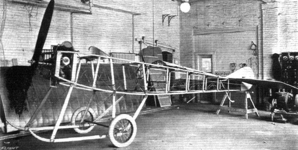
The body presents a very good streamline, being rectangular in section, tapering to a vertical knife-edge at the rear, and having a turtle deck. It is built up in two sections, of ash longitudinals and struts in the forward portion and spruce in the rear, the whole frame being well braced with heavy gauge wire, whilst the joints are all connected by means of specially-designed steel fittings, which obviate the necessity of piercing the longitudinals. The 7-cylinder 90 h.p. Gyro engine is mounted on two steel beds rigidly secured to the longitudinals in the nose, and is partially enclosed by an aluminium cowl. Immediately behind the engine are the fuel tanks, having a capacity for four hours' flight, and behind these are the passengers' and pilot's cockpits respectively. Forward of the cockpits the body is covered with sheet aluminium, the remainder being covered with fabric. The seats are provided with an arrangement for quickly adjusting their height. The Deperdussin type of control is fitted - a vertical wheel for lateral balance on a rocking column actuating the elevator, and a foot-operated rudder bar. The under-carriage consists of two ash skids connected to the body by three pairs of hollowed struts, and a tubular axle, sprung from the skids, carrying a pair of 26 in. by 4 in. wheels.
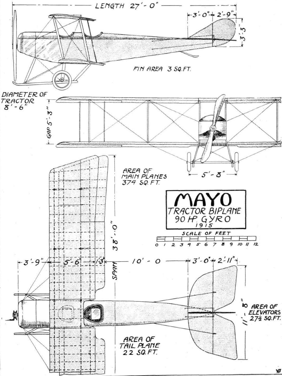
The principal dimensions of the Mayo tractor biplane are: Span, 38 ft.; chord, 5 ft. 6 ins.; gap, 5 ft. 3 ins.; supporting area, 374 sq. ft.; overall length, 27 ft.; weight, empty, 1,235 lbs.; speed, 43 to 80 miles per hour, with a landing speed of 36 m.p.h.
Flight, August 6, 1915.
THE "SIMPLEX" (MAYO) TRACTOR BIPLANE.
FURTHER particulars of the 90 h.p. Mayo type A reconnaissance tractor biplane which was described, with scale drawings and illustrations, in last week's Flight have since come to hand from America. It is stated that in view of the success of the first machines it has been decided to change the name to the "Simplex," and a separate company - the Simplex Aircraft Co. - has been organised for the purpose of building this and other types of aeroplanes and accessories on a large scale. Extensive works with an up-to-date equipment have been erected at a convenient site at New Haven, Conn., and one of the accompanying illustrations gives a fair idea of the extent of the new factory.
In addition to the type A military tractor biplane, two other types of military biplanes, both designed by Mr. Chance M. Vought, are being constructed. These are a single seater tractor scout, having a speed of 110 m.p.h., and a 175 h.p. gun-carrying pusher of somewhat large dimensions. It may be noted in passing that the high speed scout is a modification of a machine that was designed by Vought for the Aero Club of Illinois as an entry in the 1914 Gordon-Bennett race, unfortunately cancelled on account of the war.
Since its initial trial, on May 14th last, we understand that the model A tractor biplane has made nearly 200 flights, many of which have been made with a view to bringing out any weak points in design, as well as to demonstrate its flying qualities before various officials. Apparently no serious defects or deficiencies were brought to light, for it was not found necessary to make any alterations to the designer's original blue-prints, and no changes are contemplated; nor had a single wire or part been broken or replaced. The only items that have received attention are the shock absorbers on the landing chassis, which have been fitted with additional strands of rubber, and the fuel tanks, which have been enlarged. The tests further demonstrated that the machine was up to its designer's expectations as regards speed - the tests showed 3 m.p.h. more than was calculated - load carrying and climbing, with a fair margin to spare. We are informed that during the tests the machine made consistent speed averages of 83 m.p.h., and climbed 3,650 ft. in 7 mins., carrying a load of 645 lbs. including pilot and passenger. The minimum speed has not been absolutely determined owing to the unsuitable nature of the flying ground, but low speeds of 40 m.p.h. have been obtained. The best gliding speed of the machine, as measured by the air speed indicator, is 61 m.p.h., and the most efficient gliding angle is 1 in 7. As nearly as was determined, the best air speed for a full load climb was 65 m.p.h. These figures were obtained with the Ogilvie air speed indicator, working in conjunction with several other instruments of Mr. Vought's own design.
A glance at the illustration of the partly assembled fuselage, and also that of the wing frame, will reveal several interesting constructional details. For instance, in the case of the latter illustration, it will be seen that the ribs, which are constructed of 3-ply birch and mahogany, are not called upon to carry any compression stresses, functioning solely as load members. There are, however, three stout cross-struts between the spars which, together with the wire bracing, take all compression stresses. It will also be noticed that the spars are of substantial proportions, channelled out for lightness at intervals, and that the trailing edge is of steel tubing. Note should also be made of the steel fittings at the various joints, &c, which obviate the piercing of the spars and other members. The control arms for the rudder, elevators and ailerons shown on the left of the illustration in question are die stampings from special sheet steel.
The method of mounting the 90 h.p. Gyro engine between two steel beds rigidly secured to the fuselage longitudinals is clearly shown in the other illustration, whilst a good view of the control may be obtained. All the moving members of the latter have ball-bearing shafts, wheels and pulleys. As in the case of the planes, steel fittings are to be found connecting the various members, so that nowhere are the longitudinals pierced. The fittings attaching the chassis struts to the body are of the quick detachable type, so that the chassis can quickly be dismantled. In fact, quick detachable fittings are largely used throughout the machine, and the time taken to assemble from crates is claimed to be 28 minutes, 20 minutes being required for dismantling.
- Журнал Flight
Фотографии
-

Журнал - Flight за 1915 г.
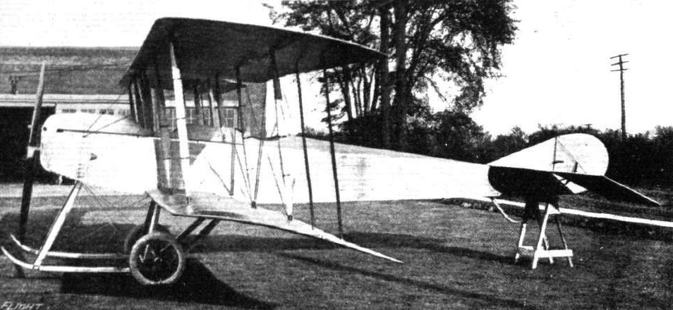
Side view of the 90 h.p. Mayo tractor biplane.
-

Журнал - Flight за 1915 г.
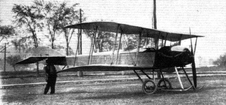
A view from the front of the 90 h.p. "Simplex" (Mayo), type A, reconnaissance tractor biplane.
-

Журнал - Flight за 1915 г.
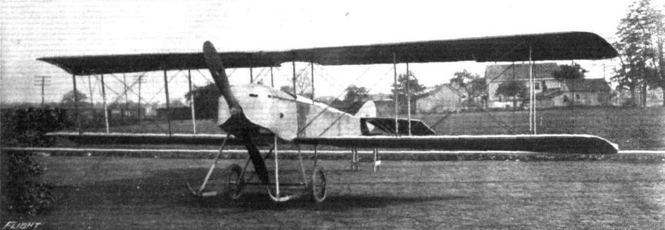
Another view of the 90 h.p. "Simplex" (Mayo) reconnaissance tractor biplane.
-

Журнал - Flight за 1915 г.
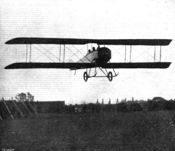
The 90 h.p. Mayo tractor biplane in flight.
-

Журнал - Flight за 1915 г.
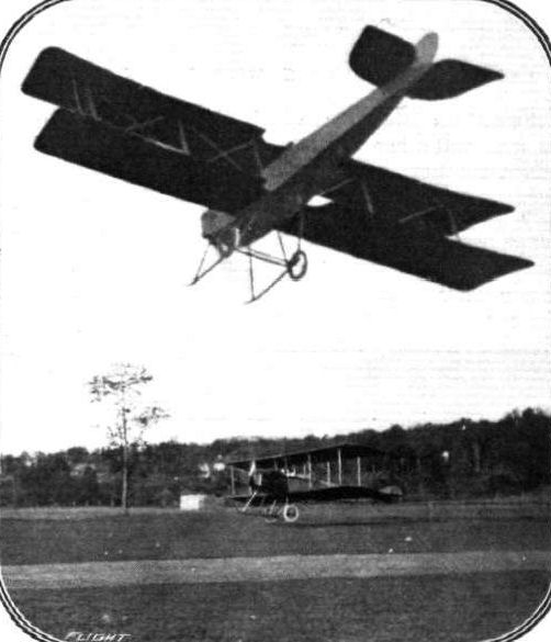
Two views of the 90 h.p. "Simplex" (Mavo) tractor biplane in flight. Below, just getting off with three passengers.
-

Журнал - Flight за 1915 г.
The partly assembled fuselage of the 90 h.p. "Simplex" (Mayo) tractor biplane. This view gives a good idea as to the substantial construction.
-

Журнал - Flight за 1915 г.
Constructional details of the 90 h.p. "Simplex" (Mayo) tractor biplane. - Left: Two control arms, as fitted to the elevators, ailerons and rudders. Right: The framework of one of the main planes. Note the cross struts for taking compression stresses.
-

Журнал - Flight за 1916 г.
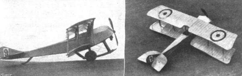
A couple of views of a well-made scale model of the Simolex-Mayo tractor - constructed from the scale drawings in "FLIGHT."

-

Журнал - Flight за 1915 г.
THE 90 H.P. MAY0 TRACTOR BIPLANE. - Plan, side and front elevation to scale.