
Книги
Журнал
Flight за 1916 г.
190
Журнал - Flight за 1916 г.
Flight, January 6, 1916.
A Model Taube.
Mr. David Hay writes from Denny, Scotland, as follows :-
"I enclose two photos, of my Etrich Taube, which was built from drawings which appeared in 'FLIGHT.' Length, 5 ft. ; span, 5ft. 9 ins. propeller, 16 ins. diameter; wheels, 2 3/4 ins. diameter; fitted with pilot's and passenger's seats; and all parts workable, all planes double surfaced. I made the model for Christmas, and took the photos, before doping the machine, as I had an idea that the dope would change the colour of same. It took me three months to complete, but I made some flying models in between that time; I think that is the best way when making such a model. I can get a good 1/4 mile out of my twin-propeller monoplane, which is flying nearly every Saturday. I must say that 'FLIGHT' is the only paper that is worth reading on such a subject."
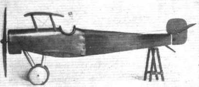
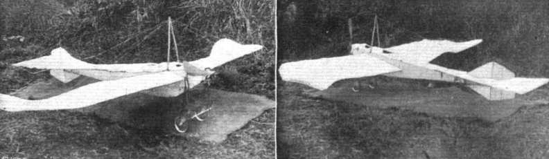
Two views of Mr. Hay's scale model Taube referred to above.
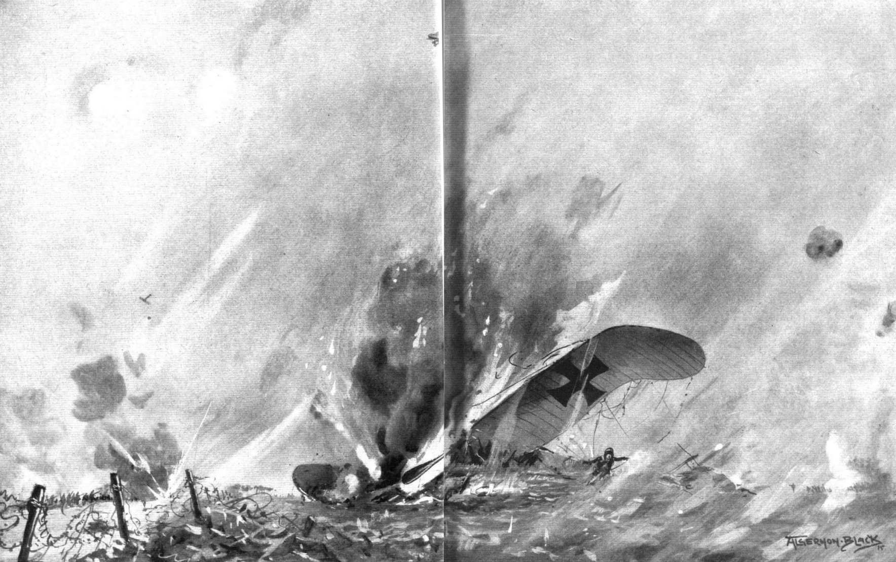
BROUGHT DOWN BETWEEN THE LINES. - As a result of many duels in mid-air between the British and German machines, enemy pilots are continually forced down between the lines, the combat being often witnessed with intense interest by both sides in the trenches. The above picture portrays one of these incidents in Flanders, in German Taube, crippled by one of the British machines, has fallen between the British and German lines, a blazing mass.
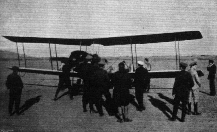
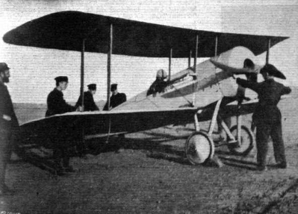
A two-seater Avro about to start for Suvla the day alter the evacuation. On the pilot's return he reported that the Turks were still shelling the empty trenches for all they were worth.
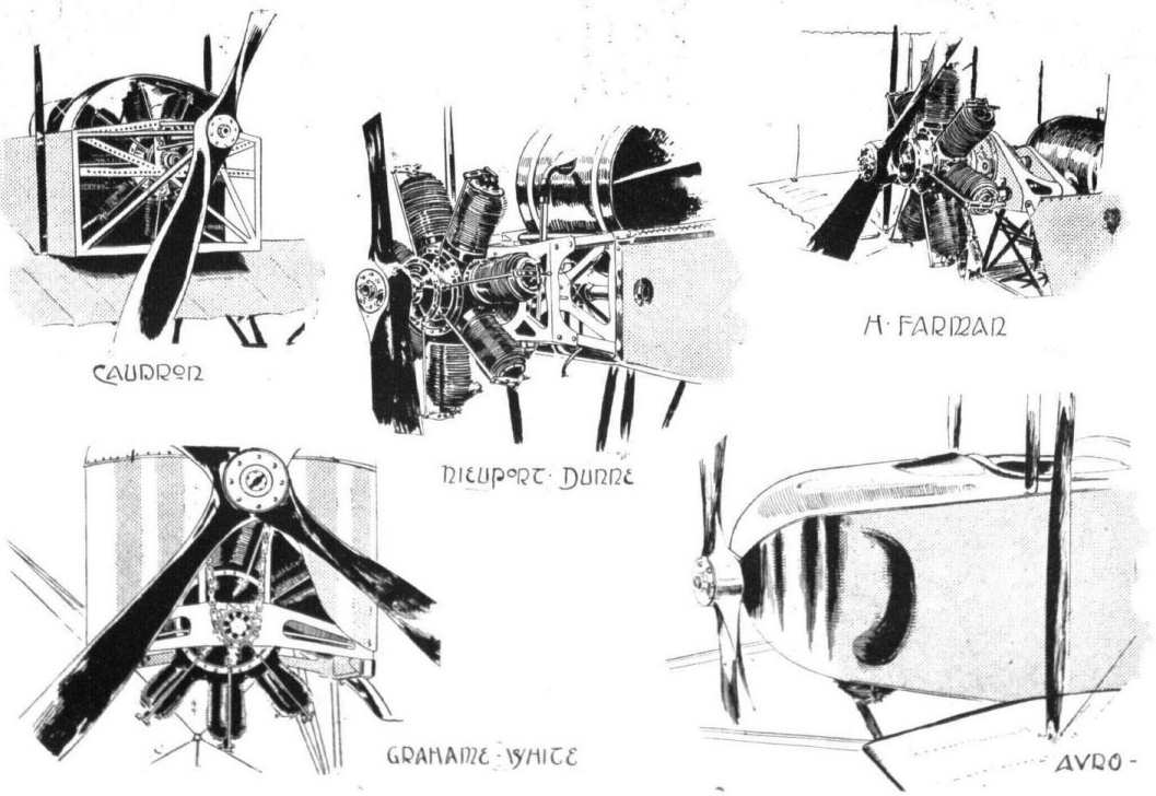
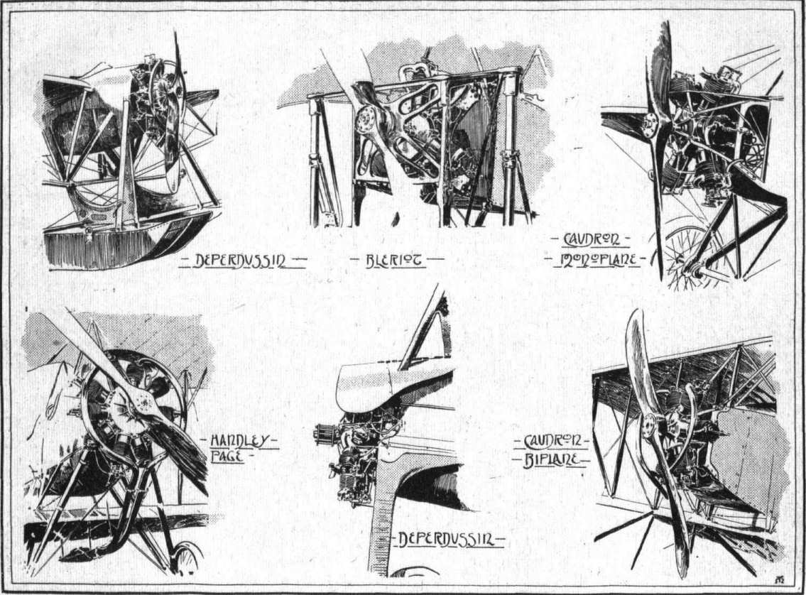
Some engine mountings ad housings on "pusher" biplanes.
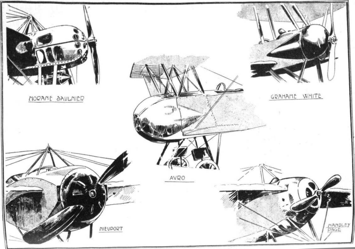
Engines mounted between double bearers, and their housings.

Mounting and housing of Vee-type air-cooled engines. Inset in centre, the Renault engine, showing tubular bearers.
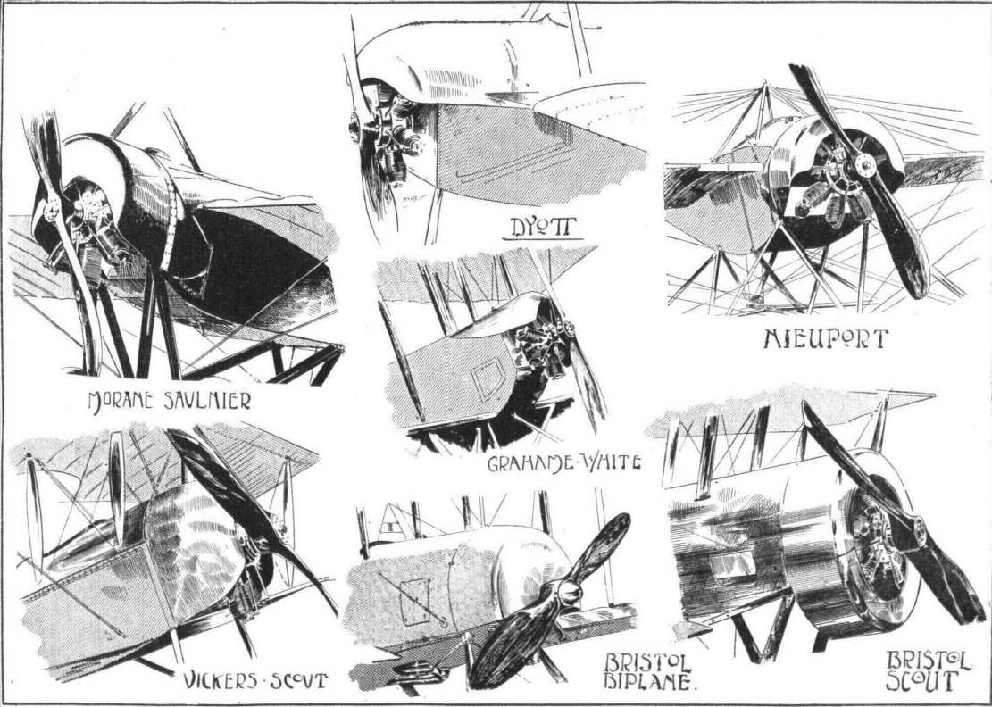
Various engine mountings and housings.
Various engine mountings and housings.
Flight, January 13, 1916.
A Model Bristol Scout.
From South Lowestoft Mr. Lewis E. Richards sends a photo, of a beautifully-made Bristol scout, of which he says :-
"Enclosed herewith are photos, of a model Bristol Scout, Type C, 1915, constructed a few months back, which might interest your Model Section.
"Made almost entirely of mahogany and copper, to a scale of 1/12th , it was primarily intended as an exhibition working model, having in view the suggestion I put forward in your columns last February in connection with the Flying Services Fund.
"Not the least interesting features incorporated in its construction are a special copper stamping for the engine housing, and a laminated air screw, whose shafting is coupled to a motor and driven by a dry battery in the fuselage.
"Controls are functioned by levers situated in the cabane, including a device for starting up and switching off the motor. To facilitate dismantling and inspection, all members are readily and easily detachable.
"Details have engaged closest attention, and to ensure accuracy, blue prints were supplied through the courtesy of Messrs. The British and Colonial Aeroplane Co., Ltd., to whom I am greatly indebted for their kind and valued assistance.
"The planes are only shown in section, pressure of business having prevented their completion."
Bristol Scout of the RNAS, with Lewis gun mounted on starboard side of the fuselage.
Model of a Bristol scout fuselage by Mr. Lewis E. Richards.
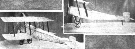
Two views of a scale model Bristol, which can be flown, made by Mr. Barrows.
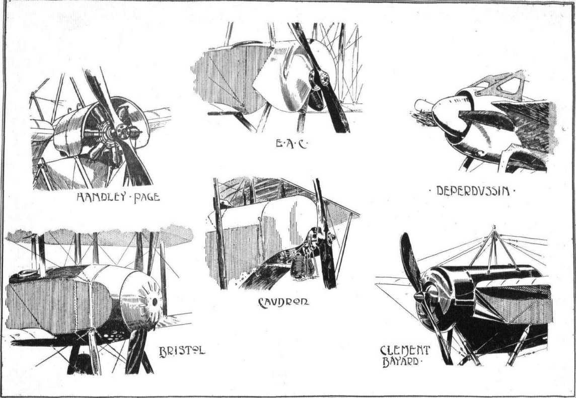
Various engine mountings and housings.
Some engine mountings ad housings on "pusher" biplanes.
Various engine mountings and housings.
Various engine mountings and housings.
Mounting and housing of Vee-type air-cooled engines. Inset in centre, the Renault engine, showing tubular bearers.
Various engine mountings and housings.
Some engine mountings ad housings on "pusher" biplanes.
Engines mounted between double bearers, and their housings.
AT HENDON. - Mr. C. Grahame-White on the new three-seater passenger 'bus.
Various engine mountings and housings.
Engines mounted between double bearers, and their housings.
Different mountings and cowls of radial air-cooled engines.
Flight, July 27, 1916.
THE NEW L. AND P. FUSELAGE BIPLANE.
A VERY neat and clean design. This is the first impression received when viewing the new biplane built by the London and Provincial Aviation Co., of Hendon, and, as in so many other cases, closer acquaintance confirms the first impression. The designer of the machine, Mr. Fletcher, who previous to joining the L. and P. firm was associated with Messrs. Martin and Handasyde of Brooklands, has managed to incorporate into a very graceful outline design a number of cleverly thought out details, and the result is a machine combining everywhere the required, and in many places a greater, factor of safety with a minimum of weight. In this connection it might be pointed out that throughout the machine all fittings are so designed as to avoid piercing any of the important members subjected to stress, such as main wing spars, body rails, &c. It is by this means that it has been possible to cut down weight without sacrificing strength, and so well have the various fittings been thought out that nowhere has the designer had to resort to a clumsy, ungainly job to get around the objectionable drilling.
From the accompanying photographs and scale drawings a good idea can be formed of the general arrangement of the new L. and P. biplane, while some of the constructional details are shown in the various sketches. The body, which is of rectangular section, is probably of as good a streamline form as it is possible to obtain without the use of formers and stringers. It is built up of ash rails, tapering and spindled out towards the rear, and connected by vertical and horizontal struts. In the rear portion the bracing is effected by wiring, while in front where, as will be seen, the covering consists of three-ply ash bracing takes the form of diagonally placed spruce struts. The wiring plates connecting the struts to the rails in the rear part of the body are some of the most ingenious we have seen, being made up of three pieces of very light gauge, the three pieces being held together by the copper eyelets in the holes for the bracing wires. The fitting is quickly and cheaply made, being, as already mentioned, of very light gauge, and by making it in two standard sizes it can be employed irrespective of the taper of the body rails.
In front a number of the metal fittings take the form of large Duralumin plates serving a variety of purposes. Several of these plates can be seen in the illustrations. A turtle back, consisting in front of three-ply wood, and at the rear of formers and stringers, tops the body and helps to give the necessary depth for effectively enclosing the occupants, of whom nothing but the heads are seen when the machine is flying. The pilot occupies the back seat, and has in front of him a neatly fitted dashboard with all the usual instruments, including engine revolution counter, altimeter, air speed indicator, clock, petrol pressure gauge, telltale oil glass, &c. In front of the pilot, and in a separate cockpit, is installed the passenger, whose seat is placed on top of the main petrol tank, which in turn rests on the bottom of the body. From this tank the fuel is forced by means of a pressure pump to a smaller service tank in the nose of the body. The controls consist of a central lever of wood mounted on a longitudinal rocking shaft, and of a foot bar for the rudder.
The engine - an 80 h.p. Anzani - is mounted in the usual manner on a capping plate bolted to the rails of the body. In order to further stiffen the mounting, two tubes are taken from the bolts of the crank-case to the top of the inner inter-plane struts. Just behind the engine the body is covered with aluminium plates, that of the top being neatly curved to form a better entry for the air.
The main planes, which are of a section somewhat similar to the R.A.F. 6, with the exception that the lower surface is slightly more cambered, 2 1/2 in. to be exact, are characterised by heavily raked tips which tend to give the machine a "racy" appearance, and which perform the more useful function of decreasing end losses and increasing the effectiveness of the ailerons. The latter are fitted to both top and bottom planes, with the result that the machine has an ample margin of lateral control, as demonstrated a few days ago, when Mr. G. Smiles, accompanied by a passenger, put up some alarming banked turns, during which the wings were repeatedly in a vertical position.
One of our sketches illustrates the attachment of the lower wing spars to short spars passing under the body.
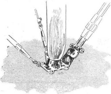
Let into each side of the centre spars is a plate, semi-circular at its outer end and angular at the inner end. Four bolts pass through each plate and through the spar. On the inner ends of the main wing spars are two similar plates, bolted to the spars in the same manner. These latter pass outside the plates on the centre spars, and a hinged joint is formed by a long hinge-pin passing through the central hole in the end of the plates from back to front spars. One end of this pin is bent over at right angles, and is prevented from coming adrift by a small aluminium clip passed over the bent end and screwed to the inner rib of the wing. In the same sketch is shown the anchorage for the lift cables. Two magnified chain-links are secured to the spars of the centre section of the lower plane by a sturdy bolt, and as the spars themselves are at this point of generous proportions, the stresses are adequately dealt with. Another point in favour of this method of passing the spars right underneath the body is that the final point of anchorage for the lift cables is immediately below the bottom rails of the body, so that no twisting strain is imposed on the rails. At the outer ends of the chain-links referred to above is another stout bolt around which passes a plate receiving the ends of the wire strainers in the manner shown in the sketch.
One of the features of the new L. and P. biplane is the type of wiring plate and inter-plane strut socket employed. One form of these consists of a rectangular plate to which the socket is welded, provided with the necessary lips for attachment of bracing cables. At each corner of this plate is a hole for a bolt passing through the wing and through a similar plate on the other side of the spar, minus the socket, of course. The four bolts on being tightened up cause the two plates to grip the spars, and the plates are further prevented from sliding along the spars on account of the obliquity of the bracing cables by letting the bolts, into the sides of the spars to the extent of half their diameters. The fitting used for the outer struts is similar, except that here only two bolts are employed, the place of the other two being taken by two strips, of the wiring plate itself bent around the side of the spar.
The hinge for the ailerons is formed by forked eye-bolts passing through the spars, and ordinary eyebolts in the leading edge of the aileron. A long wire bolt runs right through all the eyebolts, thus doing away with the ordinary short bolt and nut for each hinge, which would be somewhat inaccessible in the narrow slot between the rear spar and the aileron. An exactly similar hinge is employed for the rudder and elevators. Regarding the various members of the tail these give the impression of being unusually large, but from the severe tests of stability carried out recently it would appear that the control organs, while being large enough to ensure that any tendency to pitching or yawing is effectively stopped, are not so large as to cause any difficulty in the way of too great or weathercock stability. The fixed tail plane is of the nonlifting type in so far as it is set at no angle of incidence to the axis of the propeller, but while its lower surface is flat its upper surface is cambered to allow for the fact that it is working in the slip stream from the propeller and in the down draft from the wings. A small swivelling skid mounted on a pyramid of steel tubes, streamlined with wood fairings, protects the tail planes against contact with the ground.
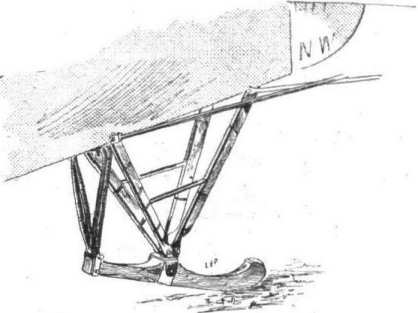
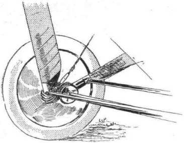
When looking casually at the machine, the chassis appears to consist of four streamline wood struts supporting the axle, but on closer examination it is found that the struts are in reality steel tubes encased in a fairing of wood. Two transverse steel tubes connect the lower apices of the Vees formed by the chassis struts, and the Duralumin tubular axle is slung from the tubular struts by rubber cord.
Altogether the London and Provincial Aviation Co. are to be congratulated on their first machine of original design. The workmanship is such as no large firm would need be ashamed of, in fact it would be difficult to improve on it, and the designer, Mr. Fletcher, has good cause to be proud of the machine from an aerodynamical as well as from a constructional point of view, seeing that it has already done some very excellent performances, including looping with two up, although the engine was far from being in concert trim, ticking, in fact, over at somewhere in the neighbourhood of 900 r.p.m. instead of the regulation 1,250. Even so the speed was something like 75 m.p.h., and when the new Lang propeller ordered for the machine arrives, this figure is expected to be considerably exceeded. The total weight "all up," including pilot, passenger, and three hours' fuel, is 1,400 lbs., which is very light for a machine of this size. We have no official figures regarding the gliding angle, but it appears to be extraordinarily good, probably in the neighbourhood of 1 in 10.
THE NEW L. AND P. FUSELAGE BIPLANE.
A VERY neat and clean design. This is the first impression received when viewing the new biplane built by the London and Provincial Aviation Co., of Hendon, and, as in so many other cases, closer acquaintance confirms the first impression. The designer of the machine, Mr. Fletcher, who previous to joining the L. and P. firm was associated with Messrs. Martin and Handasyde of Brooklands, has managed to incorporate into a very graceful outline design a number of cleverly thought out details, and the result is a machine combining everywhere the required, and in many places a greater, factor of safety with a minimum of weight. In this connection it might be pointed out that throughout the machine all fittings are so designed as to avoid piercing any of the important members subjected to stress, such as main wing spars, body rails, &c. It is by this means that it has been possible to cut down weight without sacrificing strength, and so well have the various fittings been thought out that nowhere has the designer had to resort to a clumsy, ungainly job to get around the objectionable drilling.
From the accompanying photographs and scale drawings a good idea can be formed of the general arrangement of the new L. and P. biplane, while some of the constructional details are shown in the various sketches. The body, which is of rectangular section, is probably of as good a streamline form as it is possible to obtain without the use of formers and stringers. It is built up of ash rails, tapering and spindled out towards the rear, and connected by vertical and horizontal struts. In the rear portion the bracing is effected by wiring, while in front where, as will be seen, the covering consists of three-ply ash bracing takes the form of diagonally placed spruce struts. The wiring plates connecting the struts to the rails in the rear part of the body are some of the most ingenious we have seen, being made up of three pieces of very light gauge, the three pieces being held together by the copper eyelets in the holes for the bracing wires. The fitting is quickly and cheaply made, being, as already mentioned, of very light gauge, and by making it in two standard sizes it can be employed irrespective of the taper of the body rails.
In front a number of the metal fittings take the form of large Duralumin plates serving a variety of purposes. Several of these plates can be seen in the illustrations. A turtle back, consisting in front of three-ply wood, and at the rear of formers and stringers, tops the body and helps to give the necessary depth for effectively enclosing the occupants, of whom nothing but the heads are seen when the machine is flying. The pilot occupies the back seat, and has in front of him a neatly fitted dashboard with all the usual instruments, including engine revolution counter, altimeter, air speed indicator, clock, petrol pressure gauge, telltale oil glass, &c. In front of the pilot, and in a separate cockpit, is installed the passenger, whose seat is placed on top of the main petrol tank, which in turn rests on the bottom of the body. From this tank the fuel is forced by means of a pressure pump to a smaller service tank in the nose of the body. The controls consist of a central lever of wood mounted on a longitudinal rocking shaft, and of a foot bar for the rudder.
The engine - an 80 h.p. Anzani - is mounted in the usual manner on a capping plate bolted to the rails of the body. In order to further stiffen the mounting, two tubes are taken from the bolts of the crank-case to the top of the inner inter-plane struts. Just behind the engine the body is covered with aluminium plates, that of the top being neatly curved to form a better entry for the air.
The main planes, which are of a section somewhat similar to the R.A.F. 6, with the exception that the lower surface is slightly more cambered, 2 1/2 in. to be exact, are characterised by heavily raked tips which tend to give the machine a "racy" appearance, and which perform the more useful function of decreasing end losses and increasing the effectiveness of the ailerons. The latter are fitted to both top and bottom planes, with the result that the machine has an ample margin of lateral control, as demonstrated a few days ago, when Mr. G. Smiles, accompanied by a passenger, put up some alarming banked turns, during which the wings were repeatedly in a vertical position.
One of our sketches illustrates the attachment of the lower wing spars to short spars passing under the body.
Let into each side of the centre spars is a plate, semi-circular at its outer end and angular at the inner end. Four bolts pass through each plate and through the spar. On the inner ends of the main wing spars are two similar plates, bolted to the spars in the same manner. These latter pass outside the plates on the centre spars, and a hinged joint is formed by a long hinge-pin passing through the central hole in the end of the plates from back to front spars. One end of this pin is bent over at right angles, and is prevented from coming adrift by a small aluminium clip passed over the bent end and screwed to the inner rib of the wing. In the same sketch is shown the anchorage for the lift cables. Two magnified chain-links are secured to the spars of the centre section of the lower plane by a sturdy bolt, and as the spars themselves are at this point of generous proportions, the stresses are adequately dealt with. Another point in favour of this method of passing the spars right underneath the body is that the final point of anchorage for the lift cables is immediately below the bottom rails of the body, so that no twisting strain is imposed on the rails. At the outer ends of the chain-links referred to above is another stout bolt around which passes a plate receiving the ends of the wire strainers in the manner shown in the sketch.
One of the features of the new L. and P. biplane is the type of wiring plate and inter-plane strut socket employed. One form of these consists of a rectangular plate to which the socket is welded, provided with the necessary lips for attachment of bracing cables. At each corner of this plate is a hole for a bolt passing through the wing and through a similar plate on the other side of the spar, minus the socket, of course. The four bolts on being tightened up cause the two plates to grip the spars, and the plates are further prevented from sliding along the spars on account of the obliquity of the bracing cables by letting the bolts, into the sides of the spars to the extent of half their diameters. The fitting used for the outer struts is similar, except that here only two bolts are employed, the place of the other two being taken by two strips, of the wiring plate itself bent around the side of the spar.
The hinge for the ailerons is formed by forked eye-bolts passing through the spars, and ordinary eyebolts in the leading edge of the aileron. A long wire bolt runs right through all the eyebolts, thus doing away with the ordinary short bolt and nut for each hinge, which would be somewhat inaccessible in the narrow slot between the rear spar and the aileron. An exactly similar hinge is employed for the rudder and elevators. Regarding the various members of the tail these give the impression of being unusually large, but from the severe tests of stability carried out recently it would appear that the control organs, while being large enough to ensure that any tendency to pitching or yawing is effectively stopped, are not so large as to cause any difficulty in the way of too great or weathercock stability. The fixed tail plane is of the nonlifting type in so far as it is set at no angle of incidence to the axis of the propeller, but while its lower surface is flat its upper surface is cambered to allow for the fact that it is working in the slip stream from the propeller and in the down draft from the wings. A small swivelling skid mounted on a pyramid of steel tubes, streamlined with wood fairings, protects the tail planes against contact with the ground.
When looking casually at the machine, the chassis appears to consist of four streamline wood struts supporting the axle, but on closer examination it is found that the struts are in reality steel tubes encased in a fairing of wood. Two transverse steel tubes connect the lower apices of the Vees formed by the chassis struts, and the Duralumin tubular axle is slung from the tubular struts by rubber cord.
Altogether the London and Provincial Aviation Co. are to be congratulated on their first machine of original design. The workmanship is such as no large firm would need be ashamed of, in fact it would be difficult to improve on it, and the designer, Mr. Fletcher, has good cause to be proud of the machine from an aerodynamical as well as from a constructional point of view, seeing that it has already done some very excellent performances, including looping with two up, although the engine was far from being in concert trim, ticking, in fact, over at somewhere in the neighbourhood of 900 r.p.m. instead of the regulation 1,250. Even so the speed was something like 75 m.p.h., and when the new Lang propeller ordered for the machine arrives, this figure is expected to be considerably exceeded. The total weight "all up," including pilot, passenger, and three hours' fuel, is 1,400 lbs., which is very light for a machine of this size. We have no official figures regarding the gliding angle, but it appears to be extraordinarily good, probably in the neighbourhood of 1 in 10.
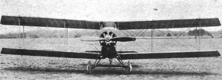
Front view of the L. and P. biplane.

Three-quarter rear view of the L. and P. biplane.
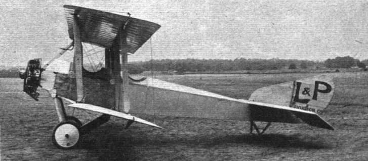
Side view of the L. and P. biplane.
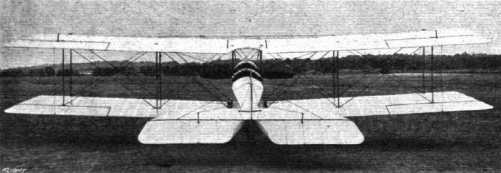
Rear view of the L. and P. biplane.
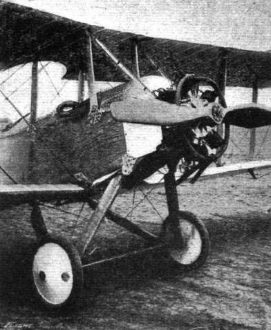
Chassis and engine mounting of the new L. and P. biplane.
AT HENDON AERODROME . - Mr. W. T. Warren, jun., on the L. and P. biplane returning to the 'drome after a looping-the-loop bout.
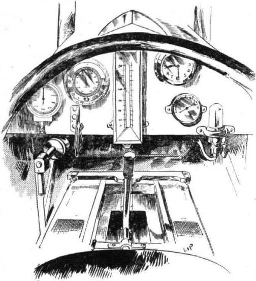
The instrument board of the L. and P. biplane.
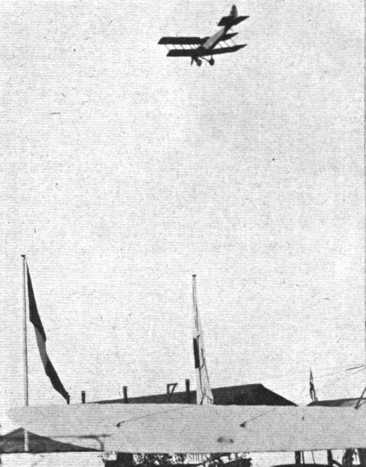
LOOPING WITH SMILES IN THE L. AND P. BIPLANE AT HENDON. - What a broadside view from a looping biplane looks like. As each loop is made the horizon line revolves round the centre of vision in a clockwise direction.
One of the strut sockets of the L. and P. biplane.
The tail skid of the L. and P. biplane.
Details of the chassis of the L. and P. biplane.
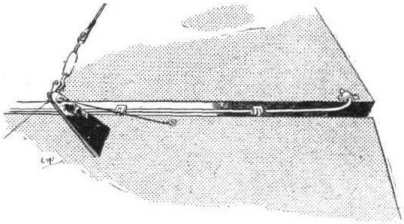
Elevator crank lever and hinge on the L. and P. biplane.
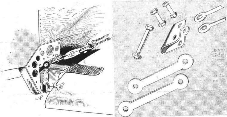
ATTACHMENT OF L. AND P. WING SPAR TO CENTRE SECTION OF LOWER PLANE. - Inset analytical sketch of the anchorage for the main lift cables.
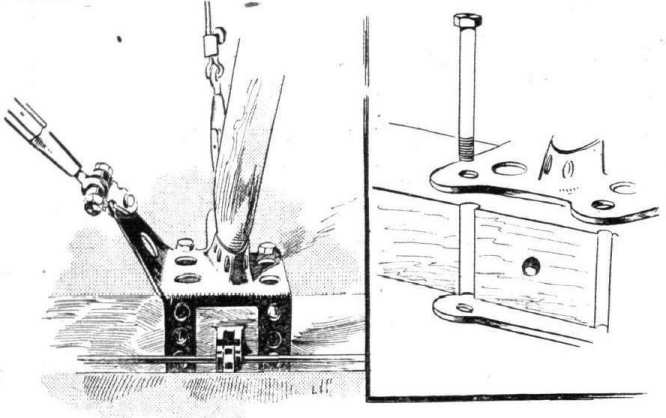
Another L. and P. Strut Socket. Inset is shown how bolts are halved into side of spar.
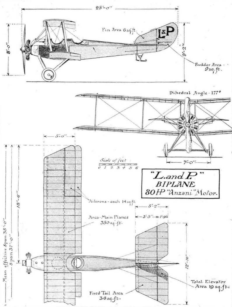
THE NEW L. AND P. FUSELAGE BIPLANE. - Plan, front and side elevation to scale.
Flight, March 9, 1916.
DESIGNING AND BUILDING A BIPLANE.
THE STORY OF A SUCCESSFUL EXPERIMENT.
By ROBERT P. GRIMMER.
[In the following story Mr. Grimmer has given a detailed summary of the ups and downs to which an experimenter in aviation has to be prepared to submit. He has adopted a very light style in handling his subject, and treats his firm's misfortunes in an almost Mark Tapley spirit, worthy of admiration. The mistakes made and the difficulties encountered should be helpful to new workers in the same direction, a suggesting what to avoid. Mr. Grimmer's views as to the comparative merits of twin-propeller and chain pusher machines as opposed to direct driven tractor machines are worth careful consideration., although it must not be taken that we necessarily are in agreement with all the author sets forth. Altogether the story is both amusing and instructive, and we heartily wish the Mann firm the success which Mr. Grimmer foretells in his concluding paragraph in connection with M.2 now under construction. - ED.]
THE Mann Gun-Carrying Biplane is probably familiar enough to the average reader of "FLIGHT," but very few people seem to know the raison d'etre of its existence. The general opinion would appear to be that the transmission was put in for a joke, or else was a misguided attempt to make the 'bus dissimilar to the ordinary type of fuselage machine. Nothing could possibly be more erroneous than these views, and I am now attempting to explain the exact reason why M.1 came into being.
The great majority of aeroplanes belong to the tractor type - that is, with the airscrew in front drawing the machine forward. The other type with the propeller behind are known as "pushers." Previous to the war, the "pusher" type had been greatly neglected, owing to the fact that its design and construction from a "performance" point of view presented great difficulties. The tail booms caused a certain amount of resistance, and there was always the possibility of their being broken by fragments of a damaged propeller. Further, there was the objection against the placing of the engine and tanks behind the crew, which, any way in theory, were liable to break loose and crush the pilot and passenger in the event of a bad landing. Whether this objection has always been substantiated by facts I am not prepared to say, but on paper the "engine-behind" machine certainly does look unhealthy.
Until the war broke out, all the best aeroplanes, without except ion, were of the tractor biplane type, and the most successful of these were single-seaters or "scouts.'' Both the British and French Governments possessed a few "pushers," but it is very doubtful if the best of these had a speed much in excess of 65-70 miles per hour, with a climb of some 300 ft. per minute. The Service value of the "pusher" consists in the excellent view obtained by the crew and the ideal gun emplacement afforded by the projecting body or nacelle. But the "tractor" scored at that time (1914) by virtue of its superior speed and climb. If by a stroke of a magic wand the Allied Governments could have transformed their "tractors" into "pushers," retaining at the same time the superior performance of the former type, there is very little reason to doubt that this would have been done at the beginning of the war. It was not until some time afterwards that the device of firing through the tractor screw was introduced by Garros. This device has the great disadvantage that the gun cannot be properly aimed, as it is on a fixed mounting. The Huns were even worse off as regards "pushers" than ouselves, as they had pinned their faith entirely to the "performance tractor."
I have explained the virtues and vices of the "tractor" and "pusher" types; the one gave good performance, medium view and a bad gun platform, and the other bad performance, good view and a super excellent gun platform. Mr. Mann and I had been connected with aviation in various capacities since its inception in 1908, and we had for some time previously recognised what we considered the disabilities of the contemporary types for Service work. The first really successful flying machine was the Wright, which in its time (1908-09) put up some quite astonishing performances, including a double crossing of the Channel with an engine giving only approximately the same horse-power (20) as the Ford tin-can car! The great characteristic of the Wright was its twin geared-down propellers driven by chains. It is an undeniable fact that propellers of large pitch rotating slowly are more efficient than propellers of small pitch rotating at very high speeds. Propeller speeds of anything up to 1,000 r.p.m. are regarded as being slow, anything approaching 2,000 r.p.m. is very fast. High speed propellers have a very large percentage of "slip," and they lack the grip on the air of the slow speed variety. There are other objections as well, the chief being the tendency to disintegrate, owing to the terrific velocity of the tips, but this latter is worse in theory than in practice, though cases are reported from time to time. At one time the Wright machine was supreme, but as the designers made no real attempt to keep pace with the times by installing really high-power engines, their "twin-pusher" was in course of time completely eclipsed by single-propeller types, chiefly of the "tractor" variety. Mr. Mann and I always recognised the possibilities of the "twin-pusher," properly developed, and we had always wished to construct such a machine on modern lines. But in those days we never secured the weighty financial backing necessary for so great a project.
Just before the outbreak of the great war Mr. Mann and I were fortunate enough to secure the interest of Mr. W, H. Bonham-Carter in our project, with the result that we were able to commence construction in September, 1914, Mr. Mann having got out the rough designs in August. I must here pay a tribute to the magnanimity and the disinterested patriotism of Mr. Bonham-Carter, who at the time of writing has tome the greater part of the burden of financing our experimental work for a period of over eighteen months, and who at the outset had no guarantee whatever that he was backing the right horse.
M.1 was designed and built at great pressure in the hope that she might be used against the Huns early in 1915. Mature reflection inclines me to the view that we should have done better if we had advanced at a more leisurely pace. The design and construction of such an experimental machine was a very big contract, so big indeed that no established constructor would have risked his reputation by taking it on. Having no reputation as constructors to lose, we took the risk - there was a distinct risk, although we were unaware of it at the time - and boldly grasped the bull by the horns. The only building we had available for the purpose was a disused tin church 20 ft. by 40 ft., with a vestry that we converted into two offices. This building had the reputation of being haunted, and it certainly had been standing empty for many years before we got possession of it. A particularly gruesome story is told about this epoch, but the episode occurred so many years ago that it is impossible to verify it. Such was the reputation of the building where M.1 was built.
M.1 was a fuselage biplane with twin chain-driven propellers. Mr, Mann, who was solely responsible for the design, was actuated by the desire to combine in one machine the virtues of the tractor and pusher without any of their vices. The wings were heavily cambered with the front edges sloped back partly for stability and partly to enable the Lewis automatic gun to be fired sideways. A 100 h. p. Anzani engine, hereafter sometimes known as the "Starfish," was mounted at the extreme prow, and the power was transmitted by means of a shaft and universal couplings to a gearbox behind the observer's seat. The gearbox was installed for the purpose of reversing one of the driving chains that emerged from it, and it weighed over 100 lbs. By the way, the reversing of one chain by any method otherwise than the Wright system of crossing it is a task sufficient to daunt the boldest designer, and is by far the biggest problem to be tackled in a chain driven aeroplane. The two chains emerging from the gearbox ran on two sprockets attached to the propeller-shafts, which were supported by means of diamond-shaped brackets and tubes and wires at the sides of the inner pair of struts. The propellers, of course, revolved in opposite directions for the sake of stability.
On September 7th, 1914, we possessed a works indifferently equipped with tools, but with neither staff nor materials, and the designs of the machine itself only roughly worked out. Yet we only allowed ourselves three months in theory to get the "steamroller" - as she was afterwards called - completed. In practice, and for the best of reasons, the construction represented five months of hard work, for it was not till the end of January, 1915, that the "steamroller" appeared at Hendon. I have never worked so hard in my life as during that five months, and the toil was so arduous, and the difficulties so numerous and complex, that the end of the period brought me a severe nervous breakdown, from which I did not finally recover until I took a month's holiday in the spring. The first difficulty we encountered was the problem of getting together an adequate staff. The next difficulty was the question of materials. The unprecedented demand for wood, fabric, sheet-steel, aluminium, tubing, nuts and bolts, wire strainers, &c., had created a veritable famine in these articles, and in some cases one had to wait months for delivery. Such material as we did get had mainly to be obtained by making personal visits to the various manufacturers and cadging - that is the only appropriate word - a sheet of steel here, a few lengths of tubing there, a dozen wire strainers, and so forth. Then there was the problem of drawings. It was well into October before we were able to get even one "stress merchant," and the middle of November before we could lay our hands on two more. In the meantime the foreman had to extemporise drawings of a kind on the back of sheets of emery paper, that being the time-honoured method employed in the early days of aviation in practically all shops.
The overtime worked during this period was something cruel; it was no uncommon thing to start work at 7 a.m. and to go on, with intervals for meals, till midnight. We frequently worked right through Friday night till noon on Saturday, and on these occasions it was not an uncommon thing for fillers to fall asleep at their vices until aroused by the fireman. On all our night shifts a pint of light ale was served out to each man at the firm's expense every two hours, and we found it very efficacious in keeping the men up to the mark. I should like here to pay a tribute to the energy and zeal of the average British workman, who has been so much decried by those who do not know him. We have never known the meaning of labour troubles, and it is my experience that in the aeroplane trade at least the average workman will deal with you as you deal by him. My far the most arduous task that fell to my personal lot was that of keeping a drawing office staff awake on the night shifts. I have sat up many a night doping the "stress merchants" with strong coffee at intervals, but in spite of this and other drastic methods more than once they were compelled to surrender to Morpheus. I recollect that on one occasion a "stress merchant" collapsed from his stool on to the floor at 3 a.m.
This particular man was a Sunday school teacher and a prominent church member, and had never been known to utter even the mildest "cuss word" on any other occasion, but when the wall was banged close to his head to arouse him, he responded with such a torrent of bad language in his sleep as shocked our most hardened fitters. We let him sleep on till breakfast, as he was obviously too muddled to distinguish "pi" from "cos," or "sine" from "tan."
With much labour the "steam-roller," was completed at the end of January, 1915, and duly transported to Hendon, permission having finally been obtained from the somewhat reluctant authorities.
It was erected early in February, and no sooner was she ready for her maiden flight when the pilot we had engaged to fly her discovered that he had more pressing business elsewhere. After same delay we made arrangements with Mr. W. R. Ding, and on Friday, (Friday is regarded by pilots, both aviation and marine, as a very unlucky day) February 19th, the machine was pushed out and the engine run preliminary to a flight. Strong as was my faith in the old "'bus," I shivered with terror when the engine was started and the chains began to run round the sprockets and scream through their guides.
The chains, instead of running smoothly round the sprockets as all self-respecting chains should, progressed in a series of leaps and bounds and appeared to be animated with the desire of moving sideways as well as forward. A tinny clanging noise emanated from the transmission gear, and the wires in the propeller brackets vibrated until they resembled bird cages. The propellers gave one the impression that they wanted to come forward through the inter-plane struts. However, Ding said he would make a flight, and we all let go. The "steam-roller" ran along the ground, duly lifted amid a cloud of smoke from the engine, made a short straight flight and landed somewhat abruptly. It transpired that the pilot's seat had collapsed owing to the "wood butcher" responsible for its fixing having been called away to a prayer meeting and thus forgetting to finish his job. The following day, Saturday, Ding made another flight, partially across country, but this latter quite against his wish and inclination. On attempting to turn, he discovered that the steadying effect of the twin propellers was so great that the rudder had very little effect, and he was compelled to edge the "'bus" round very gradually in order to get back. As the propellers did not suit the engine, and the throttle had jambed at two-thirds open, he had the unexpected pleasure of flying low over Collindale Avenue and only just clearing trees and houses. However, he got back all right, and had sufficient presence of mind left to fly hands off before he landed. A speed of 60 m.p.h. was attained, which was not so bad under the circumstances.
After a month spent in sundry alterations, chiefly to the transmission gear, with a view to steadying the jumping chains, a further flight of ten minutes was made on March 20th. A larger rudder and improved propellers had been designed, and this time the throttle was induced to go wide open. The improvement was quite marked, and a speed of 70 m.p.h. attained. An altitude of 1,000 ft. was reached without difficulty in a 30 m.p.h. wind. Unfortunately, however, one of the wires in the diamond supporting a propeller bracket came adrift, and the great weight of the "'bus" caused her to burst a tyre on landing. Jumping chain trouble was still prevalent, and the tail skid was not satisfactory. A week was spent in further slight modifications.
( To be concluded.)
Flight, March 16, 1916.
DESIGNING AND BUILDING A BIPLANE.
THE STORY OF A SUCCESSFUL EXPERIMENT.
By ROBERT P. GRIMMER.
(Concluded from page 206.)
ON March 38th, Ding made two further flights of 15 minutes each, taking Mr. Mann as passenger in the second one. The chains jumped worse than ever, and two of Hans Renold's experts were absolutely horrified at their extraordinary behaviour. The speed was about 70 m.p.h., but the general performance was so short of Mr. Mann's expectation that it was decided to make very drastic alterations and to install a 125 h.p. Anzani in place of the original 100 h.p. In the light of subsequent knowledge I regard the substitution of engines as a very great mistake, as it materially increased the loading and head resistance, and thus nullified the extra power. Later, I shall give a short list of the alterations, and point out the defects in the original machine, and the reasons that led to these defects. It is worthy of note that in this first Hendon period we only got in less than an hour's flying. On April 1st (of all days) we moved back to Surbiton with the "'bus" and all our impedimenta.
Now, our troubles were two in number: (1) lack of rigidity in the transmission, chiefly in the diamond-shaped stays supporting the propeller shafts, of which stays the front pair were wires and the rear pair steel tubes, and (2) the excessive weight of the machine necessary to secure a high factor of safety in so experimental a "'bus." The original machine with crew and fuel on board weighed over a ton, and the loading approximated to 9 lbs. to the square foot, but in spite of the manifest defects, its early performance of 70 m.p.h. speed and its 400-500 ft. per min. climb, put it in the very front ranks of "pushers." Had the transmission gear been as reliable as it afterwards became, there is very little doubt but that the machine would have been at once purchased by the Government, but the alterations occupied so long a period that by the time they were completed we had to face a rival in the shape of the twin-engined gun 'bus, of which more anon. When the "steamroller" was dissembled after the flight of March 28th, it was discovered that the gearbox and its plate had been moving about and bashing the petrol tank, which would assuredly have burst had the flight, in which Mr. Mann went up as passenger, been prolonged a few more minutes. Furthermore, each radius rod had sheared through its bolt at the gearbox end, with the result that the chains had each been pulling to the extent of a thousand pounds or so against the wing spars. Owing to the jambing of the safety valve in one of the petrol tanks, not the one "strafed" by the gearbox, it was on the point of bursting with the volume of air pumped into it by our automatic pump and was distorted completely out of shape. By way of climax the chains had only kept on their sprockets by a miracle. A period of drastic alterations now commenced, including a new chassis, larger wheels, new propellers to absorb the increased power, a still larger rudder, more forward stagger, and the complete elimination of wires from the transmission. The new engine necessitated heavier shafts, sprockets, chains, radius rods, bridge pieces and gearbox. The difficulty in obtaining material was so great that it was not until the end of June that we saw Hendon again.
During part of our first visit to Hendon we had been housed in one of the L. and P. sheds, but we were soon moved from this to the large Navy shed. When we returned at the end of June, we were unable to get a shed of any kind either from the Navy or the Grahame-White Co., so we were compelled to import a tent, which was pitched near the Hall School. Ding made his sixth flight on Tuesday, June 29th, and the general show the "'bus'' put up was inferior to her March form, and necessitated further experiment with propellers to recover the lost speed and climb. The ill-luck that had haunted us in the spring was still in evidence, for a serious accident was only narrowly averted during Ding's seventh flight on July 3rd, The "steamroller" had been up several minutes at a height of 1,500 feet, and was on the point of landing on vol plane, when a pupil on a Caudron taxied right in front of him. With great presence of mind Ding switched the engine on again, and had it not picked up immediately the Caudion would have been smashed to matchwood by over a ton of "steamroller'' moving through the air at 70 m.p.h. However, he was just able to jump over the "louse," the embryo pilot of which was in great need of a substantial dose of phospherine. On Sunday, July 4th, Ding made his eighth and ninth flights, in the latter of which a very interesting episode occurred. The old '"bus" was in great form and travelling at 73 m.p.h. Ding had just passed a "box-kite" to confute a rumour that the Mann was slower than machines of that type, and was banking to turn, when suddenly a shower of objects flew out behind the left rear of the machine and simultaneously everybody on the aerodrome heard a crashing report. At the same time the right-hand propeller was observed to increase its revolutions, but the "bank" grew no worse and Ding switched off, got the machine at a level keel, and landed without accident. Investigations showed that one of the steel stay tubes supporting the left hand propeller shaft had broken, and falling back into the propeller, had caused it to disintegrate. This incident was really a blessing in disguise, for it demonstrated the utter fallacy of the theory that any accident to one of the propellers of a twin-propeller machine must inevitably "crash" the '"bus."
A fortnight was spent in making a new propeller and strengthening up the propeller brackets, and on Sunday, July 18th, the "steamroller'' was again pushed out. Jupiter Pluvius had been busy during that fortnight, and the whole machine had been saturated with water which had percolated through the roof of the tent. The result of all this soaking was a shocking attack of "nonstarteris" on the part of the "starfish," which was not improved by the confusion of high tension wires 6 and 9 by a careless mechanic. The figures on the Anzani crank case, it transpired, were to be read upside down, which is somewhat embarrassing. M. Hagons, the Anzani expert, seemed greatly amused at our contusion of 6 and 9. During the following week short flights were made on July 19th, 20th and 21st, but trouble developed with both the petrol system and the air speed indicator, which restricted us to 10 minute flights at an alleged speed of 50 m.p.h. On the last day of July and August 1st some more or less "dud" flights were put up, and then Ding returned to Windermere in disgust, having flown the "'bus" altogether about three hours.
Having in the meantime secured that rara avis, a petrol pump that pumps petrol, we induced Mr. Sydney Pickles to try the machine on August 4th. For once in a way the "steamroller" was on her best behaviour, and climbed without any forcing to 3,000 ft. in ten minutes, remaining in the air the record time for her of half an hour. On the following night, Thursday, August 5th, Pickles took up Mr. Mann as passenger for an hour's flight, climbing the first 5,000 feet in less than 20 minutes. After the transmission gear had been overhauled and found quite satisfactory, Pickles took up the writer on August 21st, and Mr. Jones, of "FLIGHT," on the same day. The climb had by this time been increased to 500 ft. per minute and the speed to 75-80 m.p.h. All our troubles seemed to be over, and the machine, now highly successful, was about to be re-offered to the Government when the thunderbolt fell. Pickles was forbidden by an American firm, with which he had just completed a contract, to fly any machine but their own particular make. The fatal day was August 22nd. Pickles had flown the "'bus" almost as long as Ding, i.e., 3 hours.
A weary, discouraging wait ensued, for it was not until October 2nd that we were able to secure another pilot in the person of Mr. A. E. Bans, invalided from the Royal Flying Corps. All the intervening six weeks the poor old "steamroller" was steadily deteriorating in our damp tent, the fabric getting slacker and slacker daily, and rust collecting on all the metal parts despite paint and grease After two excellent preliminary flights of 18 minutes and 9 minutes respectively, during the second of which he carried a passenger, on the following day, October 3rd, he ascended with another passenger to the height of 5,000 ft., but as the weather was misty he decided to go no higher, and remained at that altitude for 40 minutes. After tea he took up a third passenger for 15 minutes and performed some astonishing evolutions, including heavily banked right and left-hand turns with hands off the controls, a feat that the exceptional stability of the Mann biplane renders quite easy. During all these flights the "steamroller" attained a speed of 80m.p.h., which at that time was a record pace for a two-seated "pusher" machine, and surpassed by very few two-seater "tractors". Unfortunately, after landing and taxiing some distance, the wheels became embedded in a filled-in trench, with the result that the chassis and one propeller were broken. This, however, was in no way the fault of the machine. We had a lovely job getting the "'bus" to our tent in the dark. To lift a dead weight of over a ton on to a trolley at night with only six pairs of hands and no mechanical appliances is "some" feat. Still, it was done with much pinching of ringers and uttering of strange oaths, and we "teedled" the trolley for home with one mechanic leading the way as guide and steering by the stars, a task for which his former experience in the Navy would seem to render him specially suitable. After we had been pushing and shoving for half an hour or so without any sign of the home fires in the tent, the ground seemed so very familiar that we stopped to investigate. Enquiries showed that our guide, who had that day been treated to a special "joy" ride in the "steamroller," had been celebrating the occasion to such an extent that he had been travelling in a circle. On being remonstrated with by the foreman, he immediately took that worthy's left eye between his finger and thumb with the apparent intention of plucking it out. He may have been a Bible student anxious to add practice to theory. Anyway, he and the foreman rolled about in the mud under the trolley, the old "'bus" trying to fall off on top of them in the meantime, using most horrible language, the foreman continually repeating "Leave go of my - eye, you - Hun!" Eventually the Bible student let go and staggered away into the darkness. It transpired later that he found a nice comfortable bed in the damp grass from which he only emerged to frighten Langridge with his dishevelled appearance at dawn. He had forgotten about the whole episode, which indeed would afford a fine text for a temperance lecturer. We freely forgave him, and he is one of our very best men at the present time. By the way, we had to serve out frequent rations of rum in the leaky tent to keep the staff from catching pneumonia, but this is the only time I have ever seen one of our men the worse for drink.
The damage to the "'bus" was soon repaired, and the critics of the Mann biplane were treated to six weeks of consistent flying without a mishap of any kind. During this period Bans flew the machine over 10 hours at an average speed of 80 m.p.h. and a maximum of 85, he ascended on 30 occasions and carried no fewer than 18 different passengers without any untoward incident. He secured with ease a low speed of 40 m.p.h. in spite of the exceptional heavy loading. The only direction in which the "'bus" might be held defective was the "climb." The falling off in this respect since August was simply due to the slackening off of the wing fabric caused by exposure in the damp and dripping tent. But in spite of her "soggy" wings the machine repeatedly climbed with five hours' fuel, gun and ammunition and two up to 3,000 ft. in 8 minutes, and that with a dead weight of over a ton and the wings loaded to 10 pounds per square foot. She frequently ascended to 5,000 ft., once to 7,000 ft., and once to nearly 9,000 ft. All the old faults had long since been eradicated, and the transmission gear gave no trouble at all. The Mann was undoubtedly the fastest two-seater "pusher" in existence, and the improvement since February was generally commented upon in aviation circles. It is my opinion that single-seater "scouts" cannot be regarded as serious "gun 'buses" from which proper aim can be taken, as the pilot is too occupied with his controls to give adequate attention to his gun. Such makeshift gun-carriers are only effective at pointblank range, and fall easy victims to a two-seater of distinctly less "performance."
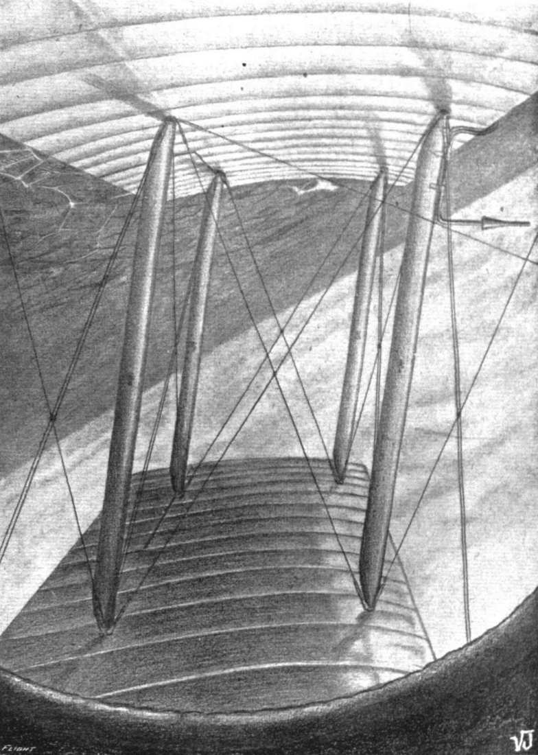
How this improvement had been effected is a long story, but I will give my readers a few details. Contrary to general expectation, the chains by themselves gave very little trouble, the stretch was negligible, and we never had a single broken roller. Their vibration, however, was the cause of the acutest anxiety to us in the early days. This vibration proceeded from a variety of causes - wires in the original propeller brackets, too long chain guides which compelled the chain to take its slack on the sprockets themselves, insufficiently rigid radius rods, and last, but by no means least, a critical period of vibration in the engine. By sheer process of elimination we eventually succeeded in inducing the chains not to jump, and a photograph in "FLIGHT" of October 29th last illustrates their smooth running. In this photograph the chains are as rigid as bars of steel. This photograph, by the way, was taken by Karrs himself from the pilot's seat, he having left go of the controls for that purpose. The bias against chains that one is constantly meeting with is surprising. There is an altogether fallacious and erroneous impression that they break! Our shafts and couplings gave no trouble at all, and we only had trouble with a propeller bracket on one occasion. Some pseudo-experts have expressed the opinion that the resistance of chains, guides and sprockets prevent high speeds from being obtained, but the fact that we were able to attain a speed of 85 m.p.h. with a crude experimental "'bus," weighing over a ton, would seem to show that there is some fallacy here. The design of the propellers involved a great deal of experiment, and we must have tried nearly a dozen pairs. The best results were obtained from the 125 h.p. engine by a pair of propellers that had proved utterly hopeless on a 100 h.p. engine. They were extremely crude in appearance, having been designed by a "wood butcher" more in joke than anything else. But with the 125 h.p. engine they pushed like elephants, giving a combined thrust of one-third the weight of the machine and licking into the proverbial cocked hat the best productions of professional propeller designers. The various propellers to Mr. Mann's own design gave excellent results, but invariably slowed the "'bus" from 5 to 10 miles per hour, while the propellers designed by the professionals pave much poorer performance.
The speed and climb of the '"bus" were worked up principally in three ways - (1) propeller experiment, (2) diminishing chain vibration, which absorbed quite a lot of power, and (3) streamlining transmission tubes and stays. Experiments with struts, both chassis and interplane, produced good results, as also did lessening the weight, but the initial ponderosity of the "steamroller" was so great that any attempt to diminish it was like sandpapering an elephant. It is the opinion of both Mr. Mann and myself that the admittedly good performance of the "'bus" was entirely due to its twin propellers, for how else could a machine weighing nearly a ton and a quarter and loaded 10 lbs. to the square foot, be induced to climb at the rate of 500 ft. per minute as actually happened when she was in good form? It is very much to be doubted if any single propeller or tractor screw would have got her off the ground at all.
Our long and protracted experimental period, which really ended in August, for Barrs had merely picked up the broken thread that Pickles had dropped, had given the mysterious "technical advisers" to the Admiralty and War Office a distinct bias against the Mann. Why, I am not prepared to say, for the practical experiments that are necessary before one can standardise a new type of aeroplane had been amply justified by the results obtained. Rehearsals are always needed before a successful public performance, and aviation is no exception to the rule. It is only on paper and in drawing offices that one designs a new type that requires neither alteration nor experiment.
However, finally, we were on the point of obtaining permission to fly the "'bus" for official trials, when she was "crashed" in an altogether unexpected manner. On November 16th Burrs had ascended with a passenger in an attempt to break the British altitude record. In about three-quarters of an hour he had ascended to a height of between 8,000 and 9,000 feet, and was still climbing strongly. Suddenly the gearbox seized up dead and the momentum of the whirling propeller broke the chain on the right-hand side. Please note that the propeller broke the chain and not the chain the propeller. The chain flew out between the two end interplane struts and vanished, as I had always prophesied it would do in the very unlikely event of a breakage, and Barrs switched off his engine and commenced a glide which lasted 21 minutes. Mr. J. G. Woodley, the passenger, was so little concerned that he calmly went on making entries in his diary, which was reproduced at the time in the pages of "FLIGHT." On nearing the ground, the poor old "'bus" was caught by a strong downward current which brought her down just outside the aerodrome in a small field. She taxied into some trees, felling three of them, but although the chassis and wings were smashed to atoms, such was the strength of the fuselage that neither Barrs nor Woodley sustained the slightest injury. The passenger's escape in particular was due to the main shaft connecting the engine and gearbox making his compartment extremely rigid and unyielding. Such a smash on an engine-behind machine would have probably left no survivors to tell the tale. The initial cause of the "crash'' was the negligence of a mechanic to put grease in the gearbox, though but for that wretched remou at the last moment the '"bus" would have landed in the aerodrome without breaking a wire. Extremely lurid and misleading accounts of the accident appeared in the pages of the contemporary daily press. Such was the end of the "steamroller" after some nine months of strenuous life.
The "crash," however, got us out of one difficulty. Our canvas hangar had become almost uninhabitable owing to the heavy rains, and a miniature river was flowing through the tent from side to side. Any further flying of the "steamroller" at Hendon had become well-nigh impossible, but the remou that brought the "'bus" down just on the wrong side of the fence effectually cut the Gordian Knot. It is worthy of note that the "steamroller" was flown three hours by Ding, three by Pickles, and 12 by Barrs, 18 hours in all, and she must have covered in that time a distance of nearly 1,500 miles.
At the time of writing, some ten weeks afterwards, we have half finished the "steamroller's" successor, M.2, who, I will venture to say without any risk of boasting, will regain for Mr. Mann the "pusher" supremacy he lost in November. M.1 all but completely vindicated the principle of chain-drive and geared down propellers; M.2, with her loading reduced to half, hundreds of pounds less in weight, will completely do so. M.1 was built in the typical "Middle Ages" manner with great clumsy fitting and full of unnecessary weight and head resistance. M.2 will be in every way an up to-date 1916 machine with transmission added. Her performance will astonish the few remaining critics of the type.
Invidious comparisons have recently been made between twin-engine and transmission machines, to the detriment of the latter. To my mind, the twin-engine machine weighs much more than a transmission machine, its head resistance is much greater, and it has more vulnerable points, e.g., two engines afford a better target for hostile fire than one, also they obviously require more attention. The twin-engine machine can fly after a fashion with one propeller, so can the transmission machine. On a transmission machine you can put your propellers where you like and run them at any desired speed. On a twin-engine machine you mutt place your engines in two particular spots, or the efficiency will suffer, and your propeller revolutions are arbitrarily fixed. Twin-engines usually indicate twin-chassis, which are not necessary on a transmission machine. The only point where the twin-engine machine scores is in simplicity, but an aeroplane transmission, once the experimental stage is passed, requires no more attention than that of a car.
My tale is told. I have made it clear to my readers why we have persevered with the Mann biplane so long, and also that the path of the experimenter is by no means easy and pleasant, though it may easily lead him to destruction. Ridicule and calumny are poured on him at every step, and all men wish him ill. He has to tight rigid conservatism and wrestle with invincible ignorance. His sole assets are the courage of his convictions and a saving sense of humour. But we forget the toil and danger of the past as we daily watch the Mann biplane rise like the Phoenix from the ashes of its predecessor. And perhaps this true story of how we wrested success from apparent failure may encourage others among the readers of "FLIGHT" to follow in our footsteps. Per Ardua ad Astra !
DESIGNING AND BUILDING A BIPLANE.
THE STORY OF A SUCCESSFUL EXPERIMENT.
By ROBERT P. GRIMMER.
[In the following story Mr. Grimmer has given a detailed summary of the ups and downs to which an experimenter in aviation has to be prepared to submit. He has adopted a very light style in handling his subject, and treats his firm's misfortunes in an almost Mark Tapley spirit, worthy of admiration. The mistakes made and the difficulties encountered should be helpful to new workers in the same direction, a suggesting what to avoid. Mr. Grimmer's views as to the comparative merits of twin-propeller and chain pusher machines as opposed to direct driven tractor machines are worth careful consideration., although it must not be taken that we necessarily are in agreement with all the author sets forth. Altogether the story is both amusing and instructive, and we heartily wish the Mann firm the success which Mr. Grimmer foretells in his concluding paragraph in connection with M.2 now under construction. - ED.]
THE Mann Gun-Carrying Biplane is probably familiar enough to the average reader of "FLIGHT," but very few people seem to know the raison d'etre of its existence. The general opinion would appear to be that the transmission was put in for a joke, or else was a misguided attempt to make the 'bus dissimilar to the ordinary type of fuselage machine. Nothing could possibly be more erroneous than these views, and I am now attempting to explain the exact reason why M.1 came into being.
The great majority of aeroplanes belong to the tractor type - that is, with the airscrew in front drawing the machine forward. The other type with the propeller behind are known as "pushers." Previous to the war, the "pusher" type had been greatly neglected, owing to the fact that its design and construction from a "performance" point of view presented great difficulties. The tail booms caused a certain amount of resistance, and there was always the possibility of their being broken by fragments of a damaged propeller. Further, there was the objection against the placing of the engine and tanks behind the crew, which, any way in theory, were liable to break loose and crush the pilot and passenger in the event of a bad landing. Whether this objection has always been substantiated by facts I am not prepared to say, but on paper the "engine-behind" machine certainly does look unhealthy.
Until the war broke out, all the best aeroplanes, without except ion, were of the tractor biplane type, and the most successful of these were single-seaters or "scouts.'' Both the British and French Governments possessed a few "pushers," but it is very doubtful if the best of these had a speed much in excess of 65-70 miles per hour, with a climb of some 300 ft. per minute. The Service value of the "pusher" consists in the excellent view obtained by the crew and the ideal gun emplacement afforded by the projecting body or nacelle. But the "tractor" scored at that time (1914) by virtue of its superior speed and climb. If by a stroke of a magic wand the Allied Governments could have transformed their "tractors" into "pushers," retaining at the same time the superior performance of the former type, there is very little reason to doubt that this would have been done at the beginning of the war. It was not until some time afterwards that the device of firing through the tractor screw was introduced by Garros. This device has the great disadvantage that the gun cannot be properly aimed, as it is on a fixed mounting. The Huns were even worse off as regards "pushers" than ouselves, as they had pinned their faith entirely to the "performance tractor."
I have explained the virtues and vices of the "tractor" and "pusher" types; the one gave good performance, medium view and a bad gun platform, and the other bad performance, good view and a super excellent gun platform. Mr. Mann and I had been connected with aviation in various capacities since its inception in 1908, and we had for some time previously recognised what we considered the disabilities of the contemporary types for Service work. The first really successful flying machine was the Wright, which in its time (1908-09) put up some quite astonishing performances, including a double crossing of the Channel with an engine giving only approximately the same horse-power (20) as the Ford tin-can car! The great characteristic of the Wright was its twin geared-down propellers driven by chains. It is an undeniable fact that propellers of large pitch rotating slowly are more efficient than propellers of small pitch rotating at very high speeds. Propeller speeds of anything up to 1,000 r.p.m. are regarded as being slow, anything approaching 2,000 r.p.m. is very fast. High speed propellers have a very large percentage of "slip," and they lack the grip on the air of the slow speed variety. There are other objections as well, the chief being the tendency to disintegrate, owing to the terrific velocity of the tips, but this latter is worse in theory than in practice, though cases are reported from time to time. At one time the Wright machine was supreme, but as the designers made no real attempt to keep pace with the times by installing really high-power engines, their "twin-pusher" was in course of time completely eclipsed by single-propeller types, chiefly of the "tractor" variety. Mr. Mann and I always recognised the possibilities of the "twin-pusher," properly developed, and we had always wished to construct such a machine on modern lines. But in those days we never secured the weighty financial backing necessary for so great a project.
Just before the outbreak of the great war Mr. Mann and I were fortunate enough to secure the interest of Mr. W, H. Bonham-Carter in our project, with the result that we were able to commence construction in September, 1914, Mr. Mann having got out the rough designs in August. I must here pay a tribute to the magnanimity and the disinterested patriotism of Mr. Bonham-Carter, who at the time of writing has tome the greater part of the burden of financing our experimental work for a period of over eighteen months, and who at the outset had no guarantee whatever that he was backing the right horse.
M.1 was designed and built at great pressure in the hope that she might be used against the Huns early in 1915. Mature reflection inclines me to the view that we should have done better if we had advanced at a more leisurely pace. The design and construction of such an experimental machine was a very big contract, so big indeed that no established constructor would have risked his reputation by taking it on. Having no reputation as constructors to lose, we took the risk - there was a distinct risk, although we were unaware of it at the time - and boldly grasped the bull by the horns. The only building we had available for the purpose was a disused tin church 20 ft. by 40 ft., with a vestry that we converted into two offices. This building had the reputation of being haunted, and it certainly had been standing empty for many years before we got possession of it. A particularly gruesome story is told about this epoch, but the episode occurred so many years ago that it is impossible to verify it. Such was the reputation of the building where M.1 was built.
M.1 was a fuselage biplane with twin chain-driven propellers. Mr, Mann, who was solely responsible for the design, was actuated by the desire to combine in one machine the virtues of the tractor and pusher without any of their vices. The wings were heavily cambered with the front edges sloped back partly for stability and partly to enable the Lewis automatic gun to be fired sideways. A 100 h. p. Anzani engine, hereafter sometimes known as the "Starfish," was mounted at the extreme prow, and the power was transmitted by means of a shaft and universal couplings to a gearbox behind the observer's seat. The gearbox was installed for the purpose of reversing one of the driving chains that emerged from it, and it weighed over 100 lbs. By the way, the reversing of one chain by any method otherwise than the Wright system of crossing it is a task sufficient to daunt the boldest designer, and is by far the biggest problem to be tackled in a chain driven aeroplane. The two chains emerging from the gearbox ran on two sprockets attached to the propeller-shafts, which were supported by means of diamond-shaped brackets and tubes and wires at the sides of the inner pair of struts. The propellers, of course, revolved in opposite directions for the sake of stability.
On September 7th, 1914, we possessed a works indifferently equipped with tools, but with neither staff nor materials, and the designs of the machine itself only roughly worked out. Yet we only allowed ourselves three months in theory to get the "steamroller" - as she was afterwards called - completed. In practice, and for the best of reasons, the construction represented five months of hard work, for it was not till the end of January, 1915, that the "steamroller" appeared at Hendon. I have never worked so hard in my life as during that five months, and the toil was so arduous, and the difficulties so numerous and complex, that the end of the period brought me a severe nervous breakdown, from which I did not finally recover until I took a month's holiday in the spring. The first difficulty we encountered was the problem of getting together an adequate staff. The next difficulty was the question of materials. The unprecedented demand for wood, fabric, sheet-steel, aluminium, tubing, nuts and bolts, wire strainers, &c., had created a veritable famine in these articles, and in some cases one had to wait months for delivery. Such material as we did get had mainly to be obtained by making personal visits to the various manufacturers and cadging - that is the only appropriate word - a sheet of steel here, a few lengths of tubing there, a dozen wire strainers, and so forth. Then there was the problem of drawings. It was well into October before we were able to get even one "stress merchant," and the middle of November before we could lay our hands on two more. In the meantime the foreman had to extemporise drawings of a kind on the back of sheets of emery paper, that being the time-honoured method employed in the early days of aviation in practically all shops.
The overtime worked during this period was something cruel; it was no uncommon thing to start work at 7 a.m. and to go on, with intervals for meals, till midnight. We frequently worked right through Friday night till noon on Saturday, and on these occasions it was not an uncommon thing for fillers to fall asleep at their vices until aroused by the fireman. On all our night shifts a pint of light ale was served out to each man at the firm's expense every two hours, and we found it very efficacious in keeping the men up to the mark. I should like here to pay a tribute to the energy and zeal of the average British workman, who has been so much decried by those who do not know him. We have never known the meaning of labour troubles, and it is my experience that in the aeroplane trade at least the average workman will deal with you as you deal by him. My far the most arduous task that fell to my personal lot was that of keeping a drawing office staff awake on the night shifts. I have sat up many a night doping the "stress merchants" with strong coffee at intervals, but in spite of this and other drastic methods more than once they were compelled to surrender to Morpheus. I recollect that on one occasion a "stress merchant" collapsed from his stool on to the floor at 3 a.m.
This particular man was a Sunday school teacher and a prominent church member, and had never been known to utter even the mildest "cuss word" on any other occasion, but when the wall was banged close to his head to arouse him, he responded with such a torrent of bad language in his sleep as shocked our most hardened fitters. We let him sleep on till breakfast, as he was obviously too muddled to distinguish "pi" from "cos," or "sine" from "tan."
With much labour the "steam-roller," was completed at the end of January, 1915, and duly transported to Hendon, permission having finally been obtained from the somewhat reluctant authorities.
It was erected early in February, and no sooner was she ready for her maiden flight when the pilot we had engaged to fly her discovered that he had more pressing business elsewhere. After same delay we made arrangements with Mr. W. R. Ding, and on Friday, (Friday is regarded by pilots, both aviation and marine, as a very unlucky day) February 19th, the machine was pushed out and the engine run preliminary to a flight. Strong as was my faith in the old "'bus," I shivered with terror when the engine was started and the chains began to run round the sprockets and scream through their guides.
The chains, instead of running smoothly round the sprockets as all self-respecting chains should, progressed in a series of leaps and bounds and appeared to be animated with the desire of moving sideways as well as forward. A tinny clanging noise emanated from the transmission gear, and the wires in the propeller brackets vibrated until they resembled bird cages. The propellers gave one the impression that they wanted to come forward through the inter-plane struts. However, Ding said he would make a flight, and we all let go. The "steam-roller" ran along the ground, duly lifted amid a cloud of smoke from the engine, made a short straight flight and landed somewhat abruptly. It transpired that the pilot's seat had collapsed owing to the "wood butcher" responsible for its fixing having been called away to a prayer meeting and thus forgetting to finish his job. The following day, Saturday, Ding made another flight, partially across country, but this latter quite against his wish and inclination. On attempting to turn, he discovered that the steadying effect of the twin propellers was so great that the rudder had very little effect, and he was compelled to edge the "'bus" round very gradually in order to get back. As the propellers did not suit the engine, and the throttle had jambed at two-thirds open, he had the unexpected pleasure of flying low over Collindale Avenue and only just clearing trees and houses. However, he got back all right, and had sufficient presence of mind left to fly hands off before he landed. A speed of 60 m.p.h. was attained, which was not so bad under the circumstances.
After a month spent in sundry alterations, chiefly to the transmission gear, with a view to steadying the jumping chains, a further flight of ten minutes was made on March 20th. A larger rudder and improved propellers had been designed, and this time the throttle was induced to go wide open. The improvement was quite marked, and a speed of 70 m.p.h. attained. An altitude of 1,000 ft. was reached without difficulty in a 30 m.p.h. wind. Unfortunately, however, one of the wires in the diamond supporting a propeller bracket came adrift, and the great weight of the "'bus" caused her to burst a tyre on landing. Jumping chain trouble was still prevalent, and the tail skid was not satisfactory. A week was spent in further slight modifications.
( To be concluded.)
Flight, March 16, 1916.
DESIGNING AND BUILDING A BIPLANE.
THE STORY OF A SUCCESSFUL EXPERIMENT.
By ROBERT P. GRIMMER.
(Concluded from page 206.)
ON March 38th, Ding made two further flights of 15 minutes each, taking Mr. Mann as passenger in the second one. The chains jumped worse than ever, and two of Hans Renold's experts were absolutely horrified at their extraordinary behaviour. The speed was about 70 m.p.h., but the general performance was so short of Mr. Mann's expectation that it was decided to make very drastic alterations and to install a 125 h.p. Anzani in place of the original 100 h.p. In the light of subsequent knowledge I regard the substitution of engines as a very great mistake, as it materially increased the loading and head resistance, and thus nullified the extra power. Later, I shall give a short list of the alterations, and point out the defects in the original machine, and the reasons that led to these defects. It is worthy of note that in this first Hendon period we only got in less than an hour's flying. On April 1st (of all days) we moved back to Surbiton with the "'bus" and all our impedimenta.
Now, our troubles were two in number: (1) lack of rigidity in the transmission, chiefly in the diamond-shaped stays supporting the propeller shafts, of which stays the front pair were wires and the rear pair steel tubes, and (2) the excessive weight of the machine necessary to secure a high factor of safety in so experimental a "'bus." The original machine with crew and fuel on board weighed over a ton, and the loading approximated to 9 lbs. to the square foot, but in spite of the manifest defects, its early performance of 70 m.p.h. speed and its 400-500 ft. per min. climb, put it in the very front ranks of "pushers." Had the transmission gear been as reliable as it afterwards became, there is very little doubt but that the machine would have been at once purchased by the Government, but the alterations occupied so long a period that by the time they were completed we had to face a rival in the shape of the twin-engined gun 'bus, of which more anon. When the "steamroller" was dissembled after the flight of March 28th, it was discovered that the gearbox and its plate had been moving about and bashing the petrol tank, which would assuredly have burst had the flight, in which Mr. Mann went up as passenger, been prolonged a few more minutes. Furthermore, each radius rod had sheared through its bolt at the gearbox end, with the result that the chains had each been pulling to the extent of a thousand pounds or so against the wing spars. Owing to the jambing of the safety valve in one of the petrol tanks, not the one "strafed" by the gearbox, it was on the point of bursting with the volume of air pumped into it by our automatic pump and was distorted completely out of shape. By way of climax the chains had only kept on their sprockets by a miracle. A period of drastic alterations now commenced, including a new chassis, larger wheels, new propellers to absorb the increased power, a still larger rudder, more forward stagger, and the complete elimination of wires from the transmission. The new engine necessitated heavier shafts, sprockets, chains, radius rods, bridge pieces and gearbox. The difficulty in obtaining material was so great that it was not until the end of June that we saw Hendon again.
During part of our first visit to Hendon we had been housed in one of the L. and P. sheds, but we were soon moved from this to the large Navy shed. When we returned at the end of June, we were unable to get a shed of any kind either from the Navy or the Grahame-White Co., so we were compelled to import a tent, which was pitched near the Hall School. Ding made his sixth flight on Tuesday, June 29th, and the general show the "'bus'' put up was inferior to her March form, and necessitated further experiment with propellers to recover the lost speed and climb. The ill-luck that had haunted us in the spring was still in evidence, for a serious accident was only narrowly averted during Ding's seventh flight on July 3rd, The "steamroller" had been up several minutes at a height of 1,500 feet, and was on the point of landing on vol plane, when a pupil on a Caudron taxied right in front of him. With great presence of mind Ding switched the engine on again, and had it not picked up immediately the Caudion would have been smashed to matchwood by over a ton of "steamroller'' moving through the air at 70 m.p.h. However, he was just able to jump over the "louse," the embryo pilot of which was in great need of a substantial dose of phospherine. On Sunday, July 4th, Ding made his eighth and ninth flights, in the latter of which a very interesting episode occurred. The old '"bus" was in great form and travelling at 73 m.p.h. Ding had just passed a "box-kite" to confute a rumour that the Mann was slower than machines of that type, and was banking to turn, when suddenly a shower of objects flew out behind the left rear of the machine and simultaneously everybody on the aerodrome heard a crashing report. At the same time the right-hand propeller was observed to increase its revolutions, but the "bank" grew no worse and Ding switched off, got the machine at a level keel, and landed without accident. Investigations showed that one of the steel stay tubes supporting the left hand propeller shaft had broken, and falling back into the propeller, had caused it to disintegrate. This incident was really a blessing in disguise, for it demonstrated the utter fallacy of the theory that any accident to one of the propellers of a twin-propeller machine must inevitably "crash" the '"bus."
A fortnight was spent in making a new propeller and strengthening up the propeller brackets, and on Sunday, July 18th, the "steamroller'' was again pushed out. Jupiter Pluvius had been busy during that fortnight, and the whole machine had been saturated with water which had percolated through the roof of the tent. The result of all this soaking was a shocking attack of "nonstarteris" on the part of the "starfish," which was not improved by the confusion of high tension wires 6 and 9 by a careless mechanic. The figures on the Anzani crank case, it transpired, were to be read upside down, which is somewhat embarrassing. M. Hagons, the Anzani expert, seemed greatly amused at our contusion of 6 and 9. During the following week short flights were made on July 19th, 20th and 21st, but trouble developed with both the petrol system and the air speed indicator, which restricted us to 10 minute flights at an alleged speed of 50 m.p.h. On the last day of July and August 1st some more or less "dud" flights were put up, and then Ding returned to Windermere in disgust, having flown the "'bus" altogether about three hours.
Having in the meantime secured that rara avis, a petrol pump that pumps petrol, we induced Mr. Sydney Pickles to try the machine on August 4th. For once in a way the "steamroller" was on her best behaviour, and climbed without any forcing to 3,000 ft. in ten minutes, remaining in the air the record time for her of half an hour. On the following night, Thursday, August 5th, Pickles took up Mr. Mann as passenger for an hour's flight, climbing the first 5,000 feet in less than 20 minutes. After the transmission gear had been overhauled and found quite satisfactory, Pickles took up the writer on August 21st, and Mr. Jones, of "FLIGHT," on the same day. The climb had by this time been increased to 500 ft. per minute and the speed to 75-80 m.p.h. All our troubles seemed to be over, and the machine, now highly successful, was about to be re-offered to the Government when the thunderbolt fell. Pickles was forbidden by an American firm, with which he had just completed a contract, to fly any machine but their own particular make. The fatal day was August 22nd. Pickles had flown the "'bus" almost as long as Ding, i.e., 3 hours.
A weary, discouraging wait ensued, for it was not until October 2nd that we were able to secure another pilot in the person of Mr. A. E. Bans, invalided from the Royal Flying Corps. All the intervening six weeks the poor old "steamroller" was steadily deteriorating in our damp tent, the fabric getting slacker and slacker daily, and rust collecting on all the metal parts despite paint and grease After two excellent preliminary flights of 18 minutes and 9 minutes respectively, during the second of which he carried a passenger, on the following day, October 3rd, he ascended with another passenger to the height of 5,000 ft., but as the weather was misty he decided to go no higher, and remained at that altitude for 40 minutes. After tea he took up a third passenger for 15 minutes and performed some astonishing evolutions, including heavily banked right and left-hand turns with hands off the controls, a feat that the exceptional stability of the Mann biplane renders quite easy. During all these flights the "steamroller" attained a speed of 80m.p.h., which at that time was a record pace for a two-seated "pusher" machine, and surpassed by very few two-seater "tractors". Unfortunately, after landing and taxiing some distance, the wheels became embedded in a filled-in trench, with the result that the chassis and one propeller were broken. This, however, was in no way the fault of the machine. We had a lovely job getting the "'bus" to our tent in the dark. To lift a dead weight of over a ton on to a trolley at night with only six pairs of hands and no mechanical appliances is "some" feat. Still, it was done with much pinching of ringers and uttering of strange oaths, and we "teedled" the trolley for home with one mechanic leading the way as guide and steering by the stars, a task for which his former experience in the Navy would seem to render him specially suitable. After we had been pushing and shoving for half an hour or so without any sign of the home fires in the tent, the ground seemed so very familiar that we stopped to investigate. Enquiries showed that our guide, who had that day been treated to a special "joy" ride in the "steamroller," had been celebrating the occasion to such an extent that he had been travelling in a circle. On being remonstrated with by the foreman, he immediately took that worthy's left eye between his finger and thumb with the apparent intention of plucking it out. He may have been a Bible student anxious to add practice to theory. Anyway, he and the foreman rolled about in the mud under the trolley, the old "'bus" trying to fall off on top of them in the meantime, using most horrible language, the foreman continually repeating "Leave go of my - eye, you - Hun!" Eventually the Bible student let go and staggered away into the darkness. It transpired later that he found a nice comfortable bed in the damp grass from which he only emerged to frighten Langridge with his dishevelled appearance at dawn. He had forgotten about the whole episode, which indeed would afford a fine text for a temperance lecturer. We freely forgave him, and he is one of our very best men at the present time. By the way, we had to serve out frequent rations of rum in the leaky tent to keep the staff from catching pneumonia, but this is the only time I have ever seen one of our men the worse for drink.
The damage to the "'bus" was soon repaired, and the critics of the Mann biplane were treated to six weeks of consistent flying without a mishap of any kind. During this period Bans flew the machine over 10 hours at an average speed of 80 m.p.h. and a maximum of 85, he ascended on 30 occasions and carried no fewer than 18 different passengers without any untoward incident. He secured with ease a low speed of 40 m.p.h. in spite of the exceptional heavy loading. The only direction in which the "'bus" might be held defective was the "climb." The falling off in this respect since August was simply due to the slackening off of the wing fabric caused by exposure in the damp and dripping tent. But in spite of her "soggy" wings the machine repeatedly climbed with five hours' fuel, gun and ammunition and two up to 3,000 ft. in 8 minutes, and that with a dead weight of over a ton and the wings loaded to 10 pounds per square foot. She frequently ascended to 5,000 ft., once to 7,000 ft., and once to nearly 9,000 ft. All the old faults had long since been eradicated, and the transmission gear gave no trouble at all. The Mann was undoubtedly the fastest two-seater "pusher" in existence, and the improvement since February was generally commented upon in aviation circles. It is my opinion that single-seater "scouts" cannot be regarded as serious "gun 'buses" from which proper aim can be taken, as the pilot is too occupied with his controls to give adequate attention to his gun. Such makeshift gun-carriers are only effective at pointblank range, and fall easy victims to a two-seater of distinctly less "performance."
How this improvement had been effected is a long story, but I will give my readers a few details. Contrary to general expectation, the chains by themselves gave very little trouble, the stretch was negligible, and we never had a single broken roller. Their vibration, however, was the cause of the acutest anxiety to us in the early days. This vibration proceeded from a variety of causes - wires in the original propeller brackets, too long chain guides which compelled the chain to take its slack on the sprockets themselves, insufficiently rigid radius rods, and last, but by no means least, a critical period of vibration in the engine. By sheer process of elimination we eventually succeeded in inducing the chains not to jump, and a photograph in "FLIGHT" of October 29th last illustrates their smooth running. In this photograph the chains are as rigid as bars of steel. This photograph, by the way, was taken by Karrs himself from the pilot's seat, he having left go of the controls for that purpose. The bias against chains that one is constantly meeting with is surprising. There is an altogether fallacious and erroneous impression that they break! Our shafts and couplings gave no trouble at all, and we only had trouble with a propeller bracket on one occasion. Some pseudo-experts have expressed the opinion that the resistance of chains, guides and sprockets prevent high speeds from being obtained, but the fact that we were able to attain a speed of 85 m.p.h. with a crude experimental "'bus," weighing over a ton, would seem to show that there is some fallacy here. The design of the propellers involved a great deal of experiment, and we must have tried nearly a dozen pairs. The best results were obtained from the 125 h.p. engine by a pair of propellers that had proved utterly hopeless on a 100 h.p. engine. They were extremely crude in appearance, having been designed by a "wood butcher" more in joke than anything else. But with the 125 h.p. engine they pushed like elephants, giving a combined thrust of one-third the weight of the machine and licking into the proverbial cocked hat the best productions of professional propeller designers. The various propellers to Mr. Mann's own design gave excellent results, but invariably slowed the "'bus" from 5 to 10 miles per hour, while the propellers designed by the professionals pave much poorer performance.
The speed and climb of the '"bus" were worked up principally in three ways - (1) propeller experiment, (2) diminishing chain vibration, which absorbed quite a lot of power, and (3) streamlining transmission tubes and stays. Experiments with struts, both chassis and interplane, produced good results, as also did lessening the weight, but the initial ponderosity of the "steamroller" was so great that any attempt to diminish it was like sandpapering an elephant. It is the opinion of both Mr. Mann and myself that the admittedly good performance of the "'bus" was entirely due to its twin propellers, for how else could a machine weighing nearly a ton and a quarter and loaded 10 lbs. to the square foot, be induced to climb at the rate of 500 ft. per minute as actually happened when she was in good form? It is very much to be doubted if any single propeller or tractor screw would have got her off the ground at all.
Our long and protracted experimental period, which really ended in August, for Barrs had merely picked up the broken thread that Pickles had dropped, had given the mysterious "technical advisers" to the Admiralty and War Office a distinct bias against the Mann. Why, I am not prepared to say, for the practical experiments that are necessary before one can standardise a new type of aeroplane had been amply justified by the results obtained. Rehearsals are always needed before a successful public performance, and aviation is no exception to the rule. It is only on paper and in drawing offices that one designs a new type that requires neither alteration nor experiment.
However, finally, we were on the point of obtaining permission to fly the "'bus" for official trials, when she was "crashed" in an altogether unexpected manner. On November 16th Burrs had ascended with a passenger in an attempt to break the British altitude record. In about three-quarters of an hour he had ascended to a height of between 8,000 and 9,000 feet, and was still climbing strongly. Suddenly the gearbox seized up dead and the momentum of the whirling propeller broke the chain on the right-hand side. Please note that the propeller broke the chain and not the chain the propeller. The chain flew out between the two end interplane struts and vanished, as I had always prophesied it would do in the very unlikely event of a breakage, and Barrs switched off his engine and commenced a glide which lasted 21 minutes. Mr. J. G. Woodley, the passenger, was so little concerned that he calmly went on making entries in his diary, which was reproduced at the time in the pages of "FLIGHT." On nearing the ground, the poor old "'bus" was caught by a strong downward current which brought her down just outside the aerodrome in a small field. She taxied into some trees, felling three of them, but although the chassis and wings were smashed to atoms, such was the strength of the fuselage that neither Barrs nor Woodley sustained the slightest injury. The passenger's escape in particular was due to the main shaft connecting the engine and gearbox making his compartment extremely rigid and unyielding. Such a smash on an engine-behind machine would have probably left no survivors to tell the tale. The initial cause of the "crash'' was the negligence of a mechanic to put grease in the gearbox, though but for that wretched remou at the last moment the '"bus" would have landed in the aerodrome without breaking a wire. Extremely lurid and misleading accounts of the accident appeared in the pages of the contemporary daily press. Such was the end of the "steamroller" after some nine months of strenuous life.
The "crash," however, got us out of one difficulty. Our canvas hangar had become almost uninhabitable owing to the heavy rains, and a miniature river was flowing through the tent from side to side. Any further flying of the "steamroller" at Hendon had become well-nigh impossible, but the remou that brought the "'bus" down just on the wrong side of the fence effectually cut the Gordian Knot. It is worthy of note that the "steamroller" was flown three hours by Ding, three by Pickles, and 12 by Barrs, 18 hours in all, and she must have covered in that time a distance of nearly 1,500 miles.
At the time of writing, some ten weeks afterwards, we have half finished the "steamroller's" successor, M.2, who, I will venture to say without any risk of boasting, will regain for Mr. Mann the "pusher" supremacy he lost in November. M.1 all but completely vindicated the principle of chain-drive and geared down propellers; M.2, with her loading reduced to half, hundreds of pounds less in weight, will completely do so. M.1 was built in the typical "Middle Ages" manner with great clumsy fitting and full of unnecessary weight and head resistance. M.2 will be in every way an up to-date 1916 machine with transmission added. Her performance will astonish the few remaining critics of the type.
Invidious comparisons have recently been made between twin-engine and transmission machines, to the detriment of the latter. To my mind, the twin-engine machine weighs much more than a transmission machine, its head resistance is much greater, and it has more vulnerable points, e.g., two engines afford a better target for hostile fire than one, also they obviously require more attention. The twin-engine machine can fly after a fashion with one propeller, so can the transmission machine. On a transmission machine you can put your propellers where you like and run them at any desired speed. On a twin-engine machine you mutt place your engines in two particular spots, or the efficiency will suffer, and your propeller revolutions are arbitrarily fixed. Twin-engines usually indicate twin-chassis, which are not necessary on a transmission machine. The only point where the twin-engine machine scores is in simplicity, but an aeroplane transmission, once the experimental stage is passed, requires no more attention than that of a car.
My tale is told. I have made it clear to my readers why we have persevered with the Mann biplane so long, and also that the path of the experimenter is by no means easy and pleasant, though it may easily lead him to destruction. Ridicule and calumny are poured on him at every step, and all men wish him ill. He has to tight rigid conservatism and wrestle with invincible ignorance. His sole assets are the courage of his convictions and a saving sense of humour. But we forget the toil and danger of the past as we daily watch the Mann biplane rise like the Phoenix from the ashes of its predecessor. And perhaps this true story of how we wrested success from apparent failure may encourage others among the readers of "FLIGHT" to follow in our footsteps. Per Ardua ad Astra !
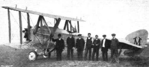
The Mann biplane M.1, and some of those who helped to build her.
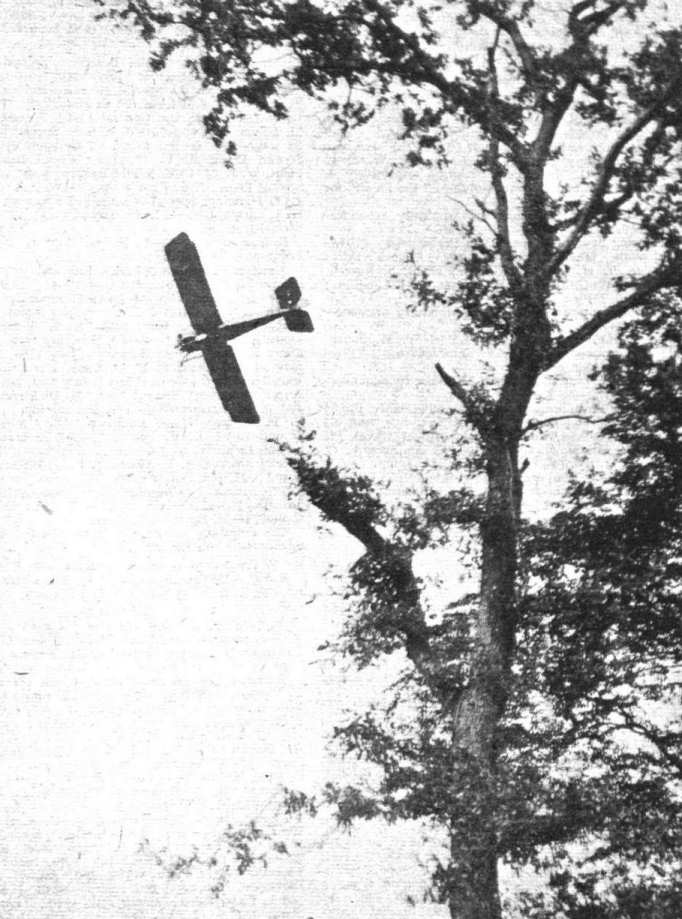
"DOING SOMETHING FOR MOTHER." - Mr. Sykes on the Martinsyde making a heavily banked turn over the trees at Hanworth Park on "Mothers' Day."
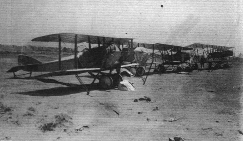
The first aeroplanes in the campaign in Mesopotamia where they have been used for carrying supplies to General Townshend's forces besieged in Kut.

A"live" combination. - A Martinside biplane and, inset, its pilot and pilot-owner, H. Sykes and C.H. Stevens. Sykes has for some time past been putting up wonderful stunts on this machine. Although bearing the marks of a nasty aeroplane smash experienced early in the year, Stevens was so keen on flying as to buy the machine and learn to fly it under the tutorship of Sykes.
Flight, November 30, 1916.
THE DEATH OF SIR HIRAM MAXIM.
BY the death of Sir Hiram Maxim aviation has lost one of its notable pioneers, although the world-fame brought to Sir Hiram by his invention of the Maxim gun overshadowed his work in connection with aeronautics. Being of a very mechanical turn of mind, it was, perhaps, not unnatural that he should attack the problem of making a machine to navigate the air, and in 1894 he experimented at Baldwyn's Park, Bexley, with a giant biplane fitted with a steam engine of 400 h.p. So sure was the inventor that the machine would lift, that he had special guards fitted to the track to prevent the aeroplane rising more than a few inches. And they proved its undoing, for the lift led to the breaking of one of the axles, while one of the guards was torn-up and catching the propeller smashed it, besides seriously damaging other parts of the machine. Those who are interested in these experiments will find a brief resume of them, written by Sir Hiram Maxim, in "FLIGHT" of March, 1910. Although Sir Hiram was convinced of the practicability of his machine, he saw that he would have to abandon the steam plant en account of the amount of water required for a long flight. He therefore set to work to design an internal combustion engine, but a severe illness, followed by great pressure of work in connection with his many other inventions, led to the scheme being abandoned. In 1909 Sir Hiram Maxim built a new biplane, this time at Erith, and full details, with photographs and scale drawings of the completed machine, were given in "FLIGHT" of April 30th, 1910.
In 1909 Sir Hiram Maxim published a little book, "Artificial and Natural Flight," which set forth the results of Sir Hiram's experiments to ascertain the relative effects produced by winds of known velocity upon objects of different shape, and also the resistance offered by similar shaped bodies passing through the air. Coming as it did at a time when there was not a great deal of literature available of a practical nature, this book, although the experiments were unfinished and the results unchecked, proved of great use to designers in the early days.
Sir Hiram Stevens Maxim had a frank, breezy nature, which won for him friends wherever he happened to be. Born at Sangerville, Maine, U.S.A., on February 5th, 1840, he started life as a coachbuilder, and tried his hand at various trades before coming to Europe in 1881. For the latter part of his life he made England his home, and, having been naturalised, he was knighted in 1901.
The funeral took place at Norwood Cemetery on November 28th, and among the mourners were Lady Maxim (widow), Master Maxim Joubert (grandson), the Hon. H. Fletcher Moulton (representing the Controller and the Munitions Inventions Department), Sir Trevor Dawson and Mr. V. C. Vickers (representing Messrs. Vickers, Ltd., of which firm Sir Hiram Maxim was for many years a director, its title then being Vickers, Sons and Maxim)
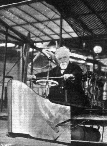
The late Sir Hiram S. Maxim, whose name is so well known throughout the world as an inventive genius. Sir Hiram is seen at the control gear of the aeroplane which he designed and built in 1910.
Flight, January 27, 1916.
A Direct-Lift Aeroplane
MANY of our readers will doubtless remember the experiments with an ornithopter, or flapping-wing, machine, which were made by M. Passat in 1910, and they will be interested to hear that, not having obtained the results anticipated, chiefly owing to mechanical difficulties in obtaining the wing movements, he has been working for some time on entirely different lines. With his latest machine, which may be described as being of the orthopter type # having revolving wings # he has obtained results which are distinctly encouraging. It is of course impossible to give full details of the invention, but it may be said that, instead of air-screws and planes as usually fitted, M. Passat employs a series of revolving wings, arranged in pairs and moving in opposite directions, so that the blades descend on the outward half of their path. By means of an ingenious cam arrangement each blade on its down stroke presents its full surface to the air, thus producing a lifting effect, while on the upstroke it is turned edgeways, i.e., "feathers," so that it offers a minimum resistance during its upward passage through the air. With the object of demonstrating his theories, M. Passat has built a model, which he will gladly show to anyone who is interested if they will communicate with hm at 106, Durham Road, Wimbledon.
Flight, August 17, 1916.
AIRISMS FROM THE FOUR WINDS,
THERE appears to be something in the Passat wing-flapping machine, and since its original debut it has passed quite beyond the wild freak machine stage. Only shows what solid conviction and consistent perseverance will do. It is only at present a decent sized crude model, but the lift is there, the power of forward motion appears to be, whilst after a short demonstration controllability and the ability to glide seem not impossible.
Flight, September 14, 1916.
Mons. Passat has for a number of years been experimenting quietly with wing-flapping machines, and has now succeeded in getting some quite promising results. In our photograph he is seen at the handle of his latest hand-operated model. Crude as it is, Mons. Passat demonstrated to us recently that he can lift with this model a weight of 80 lbs. This weight, it is true, is only lifted momentarily and not sustained for any prolonged period, but in view of the primitive arrangement even this is not bad for efficiency. Assuming that a man can develop for a short period one-fifth of a horsepower, this would give a lift, if driven by a petrol engine, of 400 lbs. per h.p., which is a somewhat startling figure. It would appear that the research authorities might not be ill-advised in granting Mons. Passat's method of imitating the flight of a bird a trial under more favourable conditions and with a mechanically improved model.

Mons. Passat and his hand-operated flapping-wing model to which reference was made in "FLIGHT" some weeks ago.
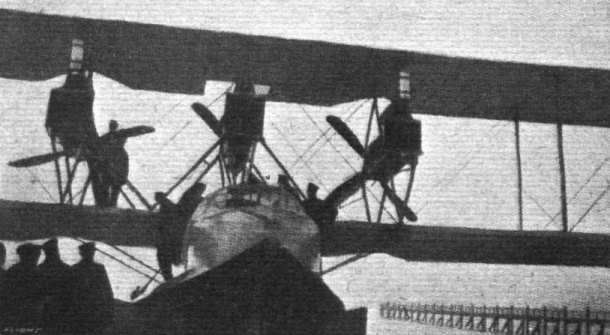
A Modern Battle-Cruiser of the Air. - The Curtiss "Super-America" flying boat, which is capable of rising from, and alighting on, very rough seas. It is equipped with three high-powered Curtiss motors.
Mounting and housing of Vee-type air-cooled engines. Inset in centre, the Renault engine, showing tubular bearers.
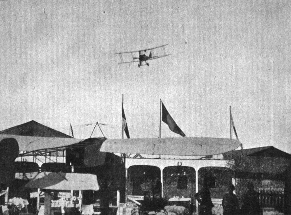
AT HENDON. - In 19-- it may be that pilots will vol plane into Mitchell's tea gardens for the cup that cheers. The one shown was probably only on a reconnaissance trip. The Bleriot, in the shade of whose wings the tables are set, is that of the late G. Lee Temple.
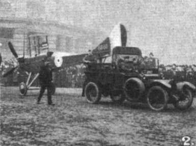
Some snaps of the Lord Mayor's Procession: - 2. Fuselage of British B.E.
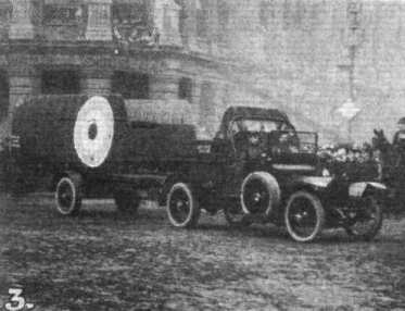
Some snaps of the Lord Mayor's Procession: - 3. Port-side wings of British B.E.
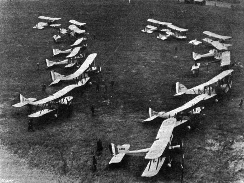
A batch of presentation aeroplanes lined up in England ready to be flown overseas.
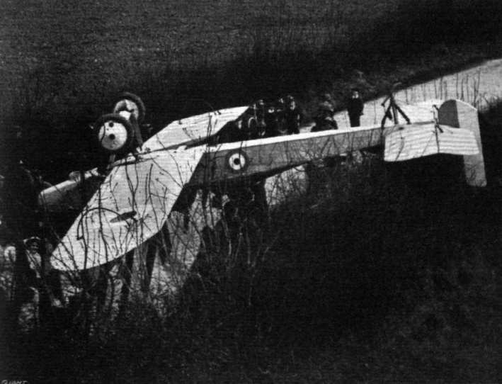
A CLEAN SOMERSAULT. - An aeroplane mishap near Basingstoke. The machine landed upside down, as will be seen, right across the road. The pilot had a remarkable escape, but being strapped in was absolutely unhurt.

AN AMPHIBIAN BIPLANE. - Owing to the shedding of a landing wheel when getting away at Hendon on Sunday last, the pilot of a reconnaissance machine chose the lesser of two evils, aud brought his mount safely to rest in the Brent Reservoir. Pilot and passenger escaped with what was a welcome ducking, the day being extremely hot, and the machine was towed safely to the side, practically undamaged.
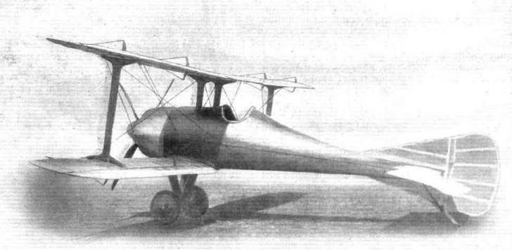
The R.A.F. S.E.4 single-seat reconnaissance machine, illustrated in Mr. F. W. Lanchester's new work, "Aircraft in Warfare." Three-quarter view from the back.
Flight, July 13, 1916.
CONSTRUCTIONAL PROGRESS AT THE RUFFY-BAUMANN SCHOOL OF FLYING.
APART from the hard usage of a machine engaged on actual war service, it is doubtful whether there exists any form of work which tests a machine more severely than that to which it is subjected at a flying school. For this reason it is a matter of some interest to follow the evolution of the various details of a school machine even if its general design follows closely along standard lines. A case in point is the school type of machine built and flown at the Ruffy-Baumann school of flying at Hendon. Although these machines are admittedly of the Caudron type - a type, by the way, which has proved itself through a number of years exceptionally suitable for instruction purposes - following closely along the lines of the original machine, a close inspection soon reveals a number of detail alterations, suggested by years of experience in school work. Some of these alterations are in the nature of strengthening up parts which, although standing up well to stresses imposed in ordinary flying, have been found somewhat liable to give way under the severe treatment frequently meted out to a machine at the hands of a beginner in the gentle art of flying, while others have been made with the object of improvement from the point of view of quickness and cheapness of manufacture rather than from one of constructional strength.
In the accompanying photographs and sketches some of the constructional details of the Ruffy-Baumann biplanes are illustrated, giving a better idea than is possible by means of a written description of the various fittings and parts employed. As the new 60 h.p. two-seater is the latest type, this has been chosen for purposes of illustration. On inspecting the machine, one of the first things one notices is the fact that the nacelle, instead of being mounted on stepped struts some little distance above the lower wing, rests with its lower longerons on the spars of this, being attached to the inner plane struts by bolts in the manner shown in one of the accompanying sketches. This gives a somewhat deeper body of rather better shape than the old one, and the cowl round the Gnome engine forms a fairly good entry for the air.
As dual control is fitted on all the machines built by the Ruffy-Baumann school, the rear engine bracing has been somewhat modified in order to provide room for the front foot bar, which, as one of our sketches shows, is in the form of a steel bar, bent to form a step into which fits the pilot's foot. Since the two bracing rods running from the rear engine bearer would have formed an obstruction to the free movement of the foot bar, they are no longer taken lo the lower corners of the nacelle, but to a point some little distance inside the corners as shown, and since this throws a bending strain on the horizontal strut, that member has been reinforced with a length of channel steel, drilled for lightness. A further alteration differing from standard practice in regard to the rear engine support will be noticed in the illustration. Instead of the usual flanged collar on the induction pipe, to which the bracing rods are attached by means of forked ends, there is a wide collar turned out of a solid steel bar. In this collar are drilled a number of holes a short distance inside the outer edge of the collar, in which are accommodated hemispherical nuts, internally threaded to receive the inner ends of the bracing rods. The arrangement will be clear from the inset in the larger sketch. It will be seen that in this manner a universal joint is formed, so that a slight discrepancy in the alignment of the attachment of the outer ends of the bracing rods and the flanged collar on the engine shaft will not be of any consequence.
With regard to some of the fittings illustrated little need be said, as the sketches are, we think, self-explanatory. The strut sockets are welded to a wiring plate secured by two bolts passing through the spar, and in the case of the point of attachment of the front skid struts these, it will be seen, no longer have square ends abutting on the flat of the front spar, but fit into sockets welded to a common base plate, thus practically being proof against any tendency to slip sideways along the spar. The diagonal bracing struts running from the lower ends of the interplane struts to the extensions of the top plane are no longer made of a steel tube with forked ends, enclosed in a fairing of wood, but are made up of solid spruce, and fitted at the ends with a socket passing over and pivoted to an eyebolt.
One of the features noticed when looking over this machine is the arrangement of the shock absorbers, which gives the impression of being very simple and substantial. Instead of the usual round rubber cord, rectangular section rubber rings are used, each ring passing over two transverse bolts, of which one is held in the lower plate passing around the skid, while the other is secured to the two T-shaped flanged steel plates attached to and, of course, moving with, the wheel axle. In case of a heavy landing one or more of the rubber rings may be broken, but the replacement of a ring or two is an operation occupying a few minutes only, and costing very little. On the other hand, when a rubber cord breaks it usually means either a new cord or an unsightly knot in the old one.
Perhaps one of the most interesting, and certainly one of the least apparent, features of the Ruffy-Baumann biplanes is the method of selecting each rib for the particular work it has to do. In other words, progressing from the wing-tips towards the centre, consecutive ribs are less elastic than the one preceding, so that at the tip, where less load is carried, the ribs are weaker, gradually increasing in rigidity towards the centre. The consequence is that when the machine is flying, the trailing edge of the whole wing forms a straight line instead of bending down in the neighbourhood of the tail booms and up as the tip is approached. There can be little doubt that this form of construction has a very important bearing on the performance of the machine.
At present there are five biplanes, all fitted with dual control and having Gnome engines of 50 and 60 h.p., in commission at the firm's school at Hendon, where extra accommodation in the form of a large tent has been provided. It might be mentioned that it is only lack of housing space that limits the number of machines, and already a similar number are waiting to be erected at the firm's works at The Burroughs, Hendon. On a recent visit to the works we found workmen busy making foundations for machinery and digging pits for the shafting, and we understand that as soon as delivery can be obtained a number of wood-working machines of various types will be installed, when the output of machines should be greatly accelerated. As a matter of fact, considering the facilities, or rather lack of them, at this firm's disposal in the past, they have turned out the machines at a very good pace, and when the new machinery has been put in, which should be in a week or two, the output will be more than equal to the requirements of the school, leaving a margin for any outside orders that may come along.
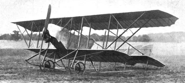
Three-quartet front view of the 60 h.p. Ruffy-Baumann school biplane.
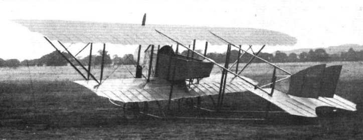
Three-quarter rear view of the 60 h.p. Ruffy-Baumann school biplane.
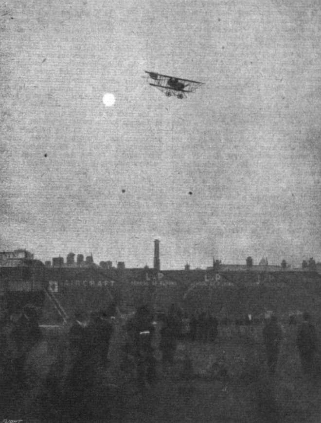
AN EVENING SCENE AT HENDON. - E. Baumann on a Ruffy-Baumann with a passenger.
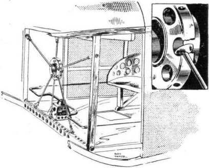
The rear engine support of the Ruffy-Baumann biplanes. Inset is shown the ball joint of the bracing rods to the collar on the engine shaft.
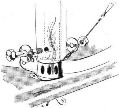
Sketch showing how the lower longerons are secured to the inner interplane struts on the Ruffy-Baumann biplanes.
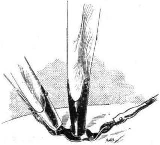
Interplane strut sockets on the Ruffy-Baumann biplanes.
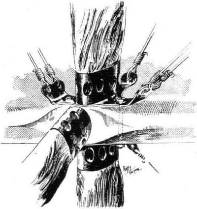
Attachment of the chassis struts to the leading edge on the Ruffy-Baumann biplanes.
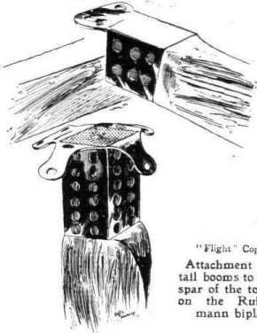
Attachment of the tail booms to the rear spar of the top plane on the Ruffy-Baumann biplanes.

Sketch showing the shock absorbing arrangement on the Ruffy-Baumann biplanes. The wheels and chassis struts have been omitted for the sake of clearness.
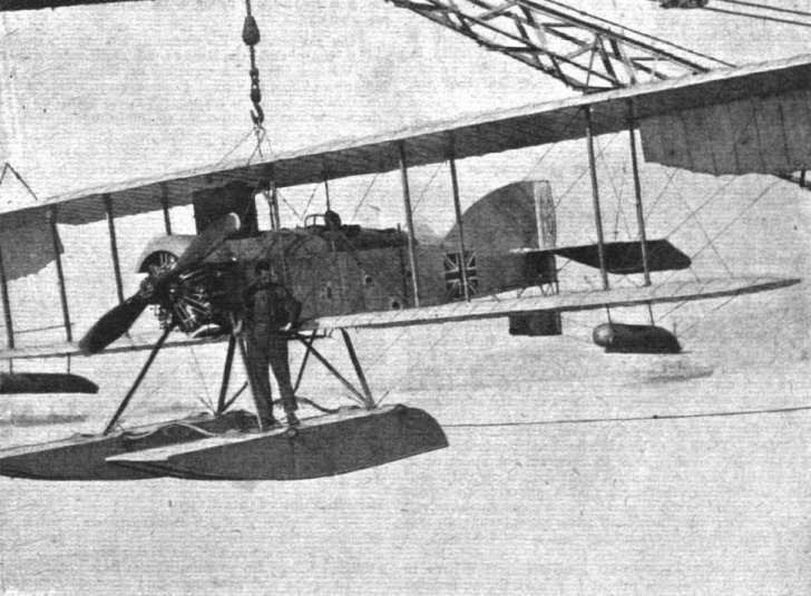
WITH THE BRITISH FORCES IN SALONICA. - Lowering a Short Type 166 folding wing seaplane in Salonica Bay from H.M.S. "Ark Royal", a seaplane carrier which has done much work in the Mediterranean.
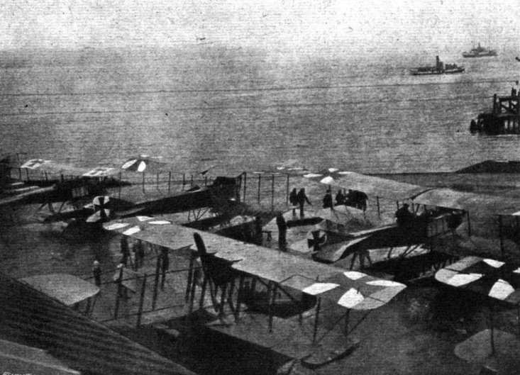
A BATCH OF GERMAN SEAPLANES AT AN AIR STATION ON THE NORTH SEA COAST. - In the foreground will be seen a bat boat of the Sopwlth type.
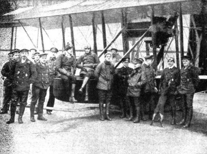
A German flying boat, type F.F.21, and some naval pilots and mechanics. - The machine is curiously like the big Sopwith bat boat exhibited at the last Olympia Aero Show, even to the engine, which appears to be similar to the Salmson. The similarity is so striking as to admit of only two explanations: either the machine is a captured Sopwith or a copy of the Sopwith built by the Flugzeugbau, Friedrichshafen.

SCALE MODEL MADE BY MR. W. M. BUNCE FROM "FLIGHT" DRAWINGS - Sopwith Tabloid.
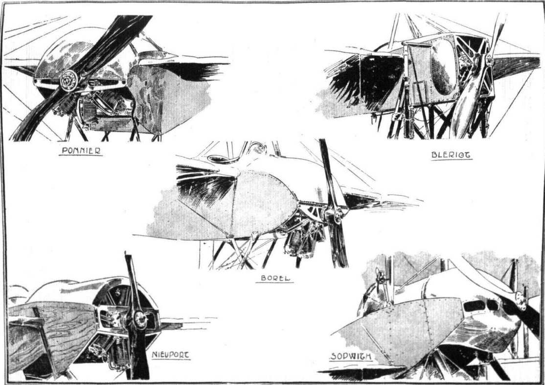
Engines mounted between double bearers, and their housings.
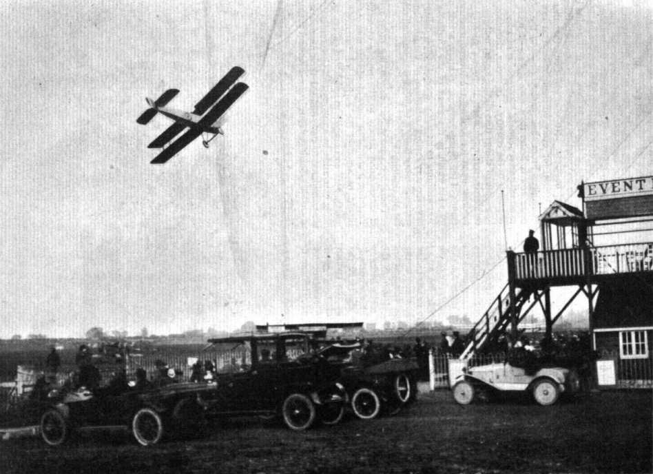
AT HENDON. - Mr. H. Hawker visits Hendon on the two-seater Sopwith "Bullet".
Entertainment of Wounded Soldiers by the Lord Mayor, Col. Sir Charles Wakefield. - Mr. Harry Hawker, on a Sopwith biplane, giving an exhibition of flying, including looping, at the Karsino, Hampton Court, on Saturday last.
Various engine mountings and housings.
Flight, January 13, 1916.
EDDIES
A correspondent in Sepang, Selangor, Malay Peninsula, sends along the accompanying photographs of the 100 h.p. Anzani-engined biplane built by Messrs. Wong and Lawford. This machine was taken out to the Straits Settlements during 1914. Mr. Wong, who may be remembered as the constructor of the Tong Mei biplane, being in charge. Through his connections out there Wong hoped to start an interest in aviation, and took out the machine in order to give practical demonstrations. For quite a long time nothing had been heard of him until the arrival of this letter, which states that several good flights were put up during early morning hours, but that later on during a demonstration flight a bad landing was made with the result shown in one of the photos. Mr. Wong fortunately was not hurt so that one may perhaps take it for granted that she will be repaired, or, if this be impossible, a new machine constructed. In all probability the engine is not seriously damaged, so that even at worst the construction of a new 'bus should not mean a very large outlay of capital. It is to be hoped that Mr. Wong will succeed in carrying out the work he has started and thus help to spread the interest in aviation. As a matter of fact this machine is not the first to fly in the Malay States, an Antoinette monoplane, piloted, I believe, by the Dutch aviator Kuller, having made flights out there as early as the beginning of 1911. Another of our photos, shows one of these. The old graceful Antoinette does not look at all out of place in its unusual surroundings.
AEOLUS
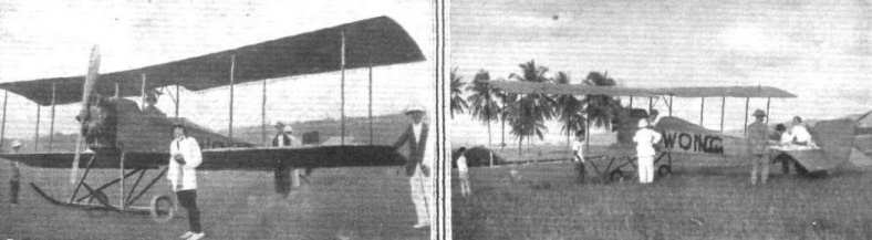
Two views of Mr. Wong's biplane on the Kuala Lumpur racecourse at Selangor, Federated Malay States.
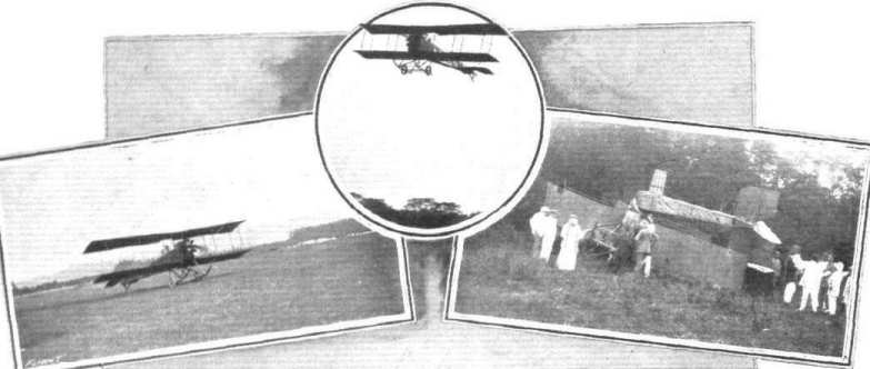
AN UNFORTUNATE EXHIBITION FLIGHT BY MR. WONG'S BIPLANE AT SELANGOR. - From left to right the pictures show the start, in full flight, and the smash.
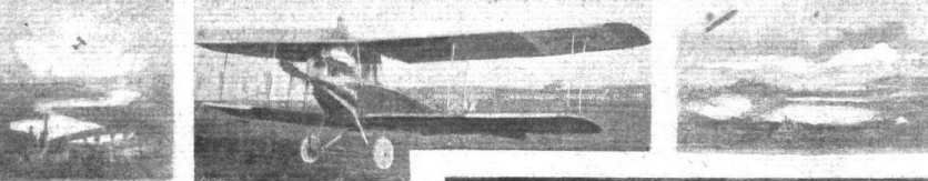
A reconnaissance two-seater, having the radiator mounted above the engine.
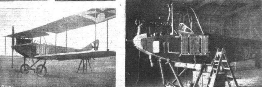
The machine on the left is of the older type, with the radiators on each side of the body. The right hand photo, is of special interest as it shows the body of an Albatros which returned from a fight with Garros with twenty bullet holes through various parts of the fuselage.
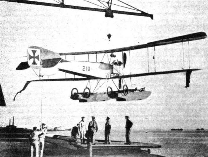
LAUNCHING A GERMAN SEAPLANE. - Before the war a good many attempts were made by German constructors at producing a combined wheel and float undercarriage so as to enable machines to start from or alight on either land or sea. In the above photograph, however, the wheels and tackle on top of the floats appear to be detachable to be used probably for running the machine short distances over land, and left behind when she takes the water. The floats, it will be observed, are of the two-stepped type, the first two sections being flat-bottomed, while the portion behind tbe rear step has a Vee bottom. The flags on the lower wing tips are in all probability fitted to a cable, and movable for signalling purposes.
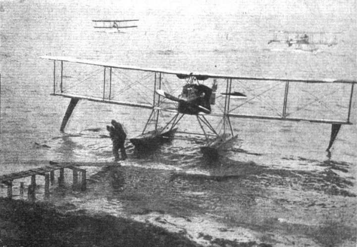
BACK FROM A SCOUTING EXPEDITION OVER THE NORTH SEA. - The pilot is being carried ashore from his craft on returning. The machine is of the F.F. 19 type. (The letters F.F. mean Flugzeugban Friedrichshafen, the German Naval Aircraft Factory.) In the background will be seen two other machines of a similar type.
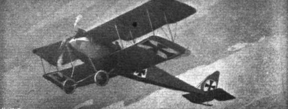
The German Halberstadt single seater, of which a good deal has been heard lately. - This machine, it will be noticed, has Morane type fuselage and tail planes. The large stationary engine is fairly effectively cowled in so as to reduce head resistance. Although being a comparatively small machine it has two pairs of struts on each side, probably necessitated by the large, heavy engine. This is one of the types with which the German pilots are getting some of their own back for our air ascendancy during the past.
Flight, June 22, 1916.
THE L.V.G. FIGHTING BIPLANE.
TYPE D.9.
GENERALLY speaking, the various makes of German aeroplanes did not present, before the war, any great divergency, all being, practically without exception, of the tractor biplane type. Such differences as did exist were, speaking aerodynamically, divisible into three main types - those which had the wings sloping back as seen in plan, those with straight wings, and those in which the leading edge sloped back while the trailing edge was straight. The first-mentioned type could be subdivided according to the amount of backward slope, the machines built by the Deutsche Flugzeug Werke of Leipzig representing the maximum and the Aviatik biplanes the minimum slope. The best-known representative of the straight-winged type is perhaps the Albatros biplanes, while the third type, which forms, so to speak, a compromise between the other two, is confined solely to the biplanes constructed by the Luft-Verkehrs-Gesellschaft of Berlin. Since the outbreak of war the tendency has been towards even greater uniformity, the type with the sloping-back wings, or, to give its German denomination, Pfeil flieger, having, as far as we are able to ascertain, practically disappeared from the western sky. The only survival is the L.V.G. type, which has retained the backward slope of its leading edge. We do not mean to infer that those firms who were producing machines of the arrow type are no longer building, but that they have - whether from choice or necessity we are not in a position to say - discarded the arrow-shaped wings for the more orthodox straight ones. At least one of the representatives of the arrow biplanes has been described in our columns, i.e., the D.F.W., which was being constructed in this country before the war broke out. Last year we also gave fully illustrated description of two of the captured Albatros biplanes, thus bringing our readers' acquaintance with the straight-winged German type up to date. This week we supplement these with a description of the third remaining type - the L.V.G. biplane.
One of the most successful German machines in the races of 1914 was the L.V.G. biplane designed by Mr. Schneider, who is, we believe, a Swiss by birth. It was a machine of this type which won the Prince Henry Race and the Ostmarken Race, and from what we can learn the L.V.G. biplanes have been no less successful as fighting machines than they were in the more peaceful contests before the outbreak of hostilities.
Apart from the backward slope of the leading edge of its main planes, the L.V.G. does not differ very greatly from the Albatros biplanes, at any rate as far as outward appearances are concerned. The same rectangular section fuselage which characterises the Albatros is found in the L.V.G., carrying at the rear a flat stabilising plane of generous proportions, and in front a large water-cooled Mercedes engine. Constructionally, however, the LV.G. does not follow the lines of the Albatros, especially as regards the construction of the body. In the Albatros biplanes, it will be remembered, the body is built up of six rafts, one in each corner of the rectangular body and one half-way up each side. The L.V.G. approaches more to the practice followed in this country and in France, having only four longitudinal rails connected in the usual way by struts, and being braced by diagonal wiring. In our description of the Albatros biplanes we ventured to offer the opinion that the Albatros way of constructing a body had several points to recommend it from a military point of view, and there is, therefore, no need to enlarge on the subject here. There are, however, points in the construction of the L.V.G. body, which might be of some use to British constructors, and which will therefore be described in detail. In the girder type of body one of the first considerations is the choice of a suitable method of anchoring the diagonal bracing wires. In the majority of machines built in this country the fittings employed for this purpose are of two types - either a steel clip bent so as to surround the body rails and provided with lips for the various wires, or a simple socket into which the strut fits, and which is secured to the rail by cue or more bolts. Both forms have their advantages and drawbacks. The clip form of fastening has the advantage that it does away with the necessity of piercing the rail, but, on the other hand, from the pilot's seat back to the stem of the body each fitting is different from the one adjoining it on each side on account of the taper which it is usual to give the rail in order to proportion it at any point to the work it has to do. This means extra expense and trouble in the manufacture and erecting, and although attempts have been made to overcome this obstacle by keeping the rails the same thickness from front to back, this only lessens the trouble, but does not overcome it entirely, since it entails spindling the rail towards the tail. The other form to which reference was made is not affected by the taper of the rails, but it suffers from the very serious disadvantage that the rails have to be pierced repeatedly, a practice which we should never recommend, although we are well aware that it is employed in a number of types of official design.
The fitting employed in the L.V.G. biplane has, it appears to us, an advantage over most of the clips or sockets that have come to our notice, in so far as it would seem to possess the good points of both forms without the disadvantages of either. The struts and cross members of the body are slotted at their ends to receive the flanges of the fitting. The latter consists of a Duralumin casting of the shape shown in the sketch. Anchorage for the five wires occurring at each joint is provided by holes in the casting, which is prevented from sliding along the rail by short small wood screws. It might be objected that piercing is not absolutely avoided, but it appears to us that although this is perfectly true the weakening of the rail due to the employment of two small wood screws for each fitting is in no way comparable in magnitude with that produced by one or more bolts that have to be of sufficient diameter to serve as an anchorage for the bracing wires. Owing to the shape of the L.V.G. fitting, it will be seen that a taper in the rail does not necessitate any variation in consecutive fittings since, if all are made of the same width as the rail at its thinnest end, the only difference will be that towards the front the struts will not have their axes in line with that of the rails.
A peculiarity in the design of the L.V.G. body is that from a point between the two cockpits to the nose the upper rails slope down in a straight line (as seen from the side; in plan they curve in the usual way). The reason for this feature of the machine, a feature that it has possessed for a number of years, is difficult to explain, unless one takes it for granted that the idea is to provide more clearance around the lower portion of the engine. The aluminium covering over the top of the body is detachable so as to facilitate access to the interior of the body in the vicinity of the engine.
In the earlier machines of this make all the occupants were accommodated in a common cockpit, but in the latest models, of which the machine illustrated this week is an example, two distinct cockpits are provided, the front one of which is occupied by the pilot, while a gunner is installed in the rear. From this position he commands a fairly free view to rearward and upward, while for firing rearwards and downwards openings are cut in the top and bottom of the body through which the machine gun may be fired. This disposition of the artillery would seem to indicate that the machine is intended for defensive rather than for offensive purposes.
The pilot, who is seated in the front seat, controls the machine by means of a foot bar and a lever terminating in a grip or handle, very similar to that of the Morane-Saulnier monoplanes. In front of him are a number of instruments almost identical with those illustrated in our description of the Albatros biplane. The engine, a 160 h.p. Mercedes, is mounted in the nose of the machine and is partly enclosed by the aluminium top cover of the body. The arrangement of the exhaust pipes is of a very simple form, consisting, as will be seen, of a short branch pipe from each cylinder running to a vertical collector pipe projecting upwards above the level of the upper plane. An unusual mounting of the radiator is employed, as will be seen from our illustrations. The radiator, instead of being mounted on the sides of the body as in earlier machines, is built into the top plane, tubes running from it down to the front and back of the engine. Whether this method of mounting is desirable for a military machine appears to us questionable. The pilot, being placed below and slightly to the rear of it, could hardly avoid being scalded should the radiator be damaged by projectiles.
The main planes, which have, as we have pointed out, their leading edge sloping back towards the tip, do not present anything out of the ordinary, either constructionally or in the section employed. The lower one is attached to the sides of the body by a quickly detachable device, while the two halves of the top plane are bolted to a steel tube cabane composed of four streamline steel tube struts resting with their lower ends on the top rails of the body.
The inter-plane struts are steel tubes of streamline section tapered at both ends to take a vertical bolt which passes through the main spar. The anchorage for the bracing cables is very similar to that employed on the Albatros machines, and consists of a hollow, cup-shaped steel shell slotted in places to accommodate the strainers of the cables. A quick-release device is employed, which allows of rapid dismantling and erecting without interfering with the adjustment of the wings. The inter-plane struts are so pivoted on the eye-bolt passing through the spar that when the cables are slackened off they can pivot sideways, and the upper and lower planes be brought to lie flat one on top of the other. The general arrangement as well as a detail drawing of the quick-release device are illustrated in two of the accompanying sketches, which are, we think, self-explanatory.
In the photographs of the machine it will be noticed that the ailerons appear to be of a very peculiar shape, the impression being that they have a narrower chord at the tip than at the root. This is not the case, however, the break being due to the fact that the outer half of the aileron is set at a slight negative angle.
In the earlier models the ailerons were similar, in that they consisted of two portions, of which the inner was in line with the trailing edge of the fixed portion of the wing, while the outer was set at a negative angle. In the new type, however, the gap between the two halves has been covered with fabric in order, presumably, to reduce end losses and thus render the aileron more effective.
The tail planes follow fairly closely along the lines of other German machines, the fixed tail plane being of large area and the rudder hinged to the rear of a fixed vertical fin. A refinement is noticeable in the arrangement of the tail skid, which has in the type D.9 the rubber shock absorber placed inside the body to save resistance.
The undercarriage is almost identical with that of the Albatros biplanes. In older models, it may be remembered, a third wheel was fitted on the lower ends of two struts sloping down from the front part of the body and braced by tubes running backwards and outwards to the apices of the Vees formed by the main chassis struts. This extra wheel has been omitted in the later model, having, in fact, always been detachable and chiefly used for school work in order to protect the propeller and prevent the machine from turning over on its nose in case of a bad landing.
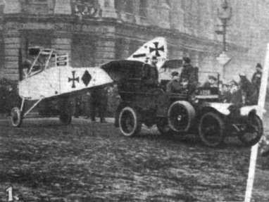
Some snaps of the Lord Mayor's Procession: - 1. Fuselage of captured German LVG.
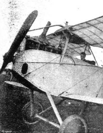
CHASSIS AND ENGINE OF AN L.V.G. BIPLANE. - Note how the radiator is built into the top place.

Three-quarter front view of a captured L.V.G. biplane.

Diagrammatic sketch of the peculiar stepped ailerons of the L.V.G. biplanes.

Sketch showing attachment of struts to body rails in the L.V.G. biplanes.
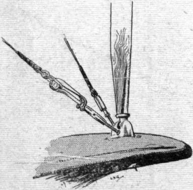
Inter plane strut socket and quick-release device on the L.V.G. biplane.
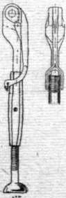
The quick release device employed in the wing bracing of an L.V.G. biplane.
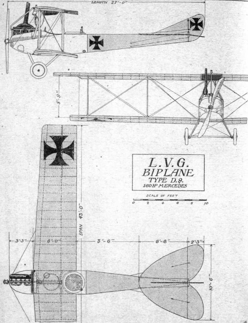
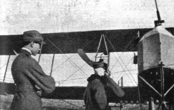
The nacelle and one of the tractor screws of a Caproni biplane. Standing in front of the machine is Capt. Salomone (with a bandage round his head), who, it will be remembered, returned from a raid on Lublana (Laibach) with both his passengers killed, he himself being wounded in the head. In spite of his wounds he put up a heroic fight against the hostile machines, and did not return until he had fulfilled his mission and dropped his full complement of bombs. In the photo he is seen regarding one of his dead comrades who has not yet been removed from the nacelle.
Flight, June 15, 1916.
THE M.F.P. TRACTOR BIPLANE.
SOME interesting and successful tests were carried out recently by Guy Gilpatric at Toronto, Canada, with a new tractor biplane that has been built in that city by the Poison Iron Works under the direction of Walter H. Phipps, who is responsible for its design. The M.F.P. biplane - the initials representing the names of Col. J. B. Miller, Walter L. Fairchild, and W. H. Phipps, the interested parties - is noteworthy on account of its steel construction. It differs from most other steel-constructed machines in that there is little or no welding, all parts and joints being made on jigs and assembled by bolting to special fittings. Most of the fittings are made, as far as possible, interchangeable, thus greatly facilitating repairs, and the number of spare parts is considerably reduced as the same fitting is used in many different places.
M.F.P. biplanes are designed in four styles, a fast single-seater scout, a two-seater scout (model D), a standard two-seater (model C), and a large-span two-seater (model B 2). With the exception of the first model, these machines differ only in the main planes, and they can be easily converted into seaplanes by the mounting of two single-step floats, which are attached to the same fittings that carry the land chassis. A factor of safety of 8 has been adopted in the design of all types. As the main characteristics of models B 2, C, and D are similar, the following description will be confined to the first-named, to which the accompanying scale drawings and photographs refer.
The main planes of a section tested at the Eiffel laboratory are of one-piece construction, very light and strong. They are built up with 3/4-inch grooved spruce battens nailed and glued to 3/16-inch hollowed, laminated birch and gumwood webs, assembled on two stout 2-inch tubular steel spars.
Each wing is trussed inside with four steel compression struts and strongly cross-braced, a construction which it is claimed adds materially to their rigidity. Top and bottom planes are separated on each side of the body by two pairs of streamline section struts, all of the same length and interchangeable on Models B 2 and C. The roots of the main spars fit into special drop-forged sockets, mounted on the fuselage for the lower plane and on the centre plane cellule for the top plane. These sockets are interchangeable, and are identical on both front and back spars. They are exceptionally light and strong, and have provision for double load wiring and front and back bracing, and, as in the case of the main spars and sockets, these struts have been subjected to most thorough tests for strength. All turnbuckles and wires have also been tested to insure the high factor of safety. The covering is Greeve's Irish aeroplane linen treated with four coats of dope.
The fuselage is rectangular in section, 30 ins. wide by 35 ins. deep in front, tapering to 14 ins. in a vertical knife edge at the rudder. The longitudinals are of steel tubing, very light, and braced with light steel tubes, joined with a special clamp, and then cross-wired. Throughout the construction of the whole machine the fuselage fittings are interchangeable. The third and fourth fuselage struts are extra large, and at the top they fit into plates which carry the extension struts to the upper plane cellule, while at the bottom they fit into simple clamps which carry the drop forgings forming lower plane attachments.
The top of the fuselage is streamlined off from the back of the pilot's seat to the tailplane by a turtle deck, which is readily detachable. Fabric is used for covering the fuselage aft of the engine portion, which is covered with sheet metal. On account of the narrow width of the fuselage - 30 inches - and the position of the passenger, well forward, with the pilot weir in back of the planes, both are afforded a good view both forward and downward.
Either a 130 h.p. Hall-Scott or the new 160 h.p. Bournonville is installed in models B 2 and C, but model D is equipped with a special 300 h.p. Duesenberg motor, fitted with electric starter. The engine is mounted on two stout laminated wood engine bearers, directly in front of the passenger and separated from him by a dash, through which a starting crank protrudes, enabling the engine to be started from the seat The petrol is fed to the engine from a large 60-gallon tank, which is sufficient for six hours' flight.
The landing chassis consists simply of two stout U frames of the same streamline section as the inter, plane struts, and cross-braced with a steel cross member of similar section. Two 26 x 4 in. disc wheels are mounted on a single axle, which is sprung on to the chassis frames by rubber shock absorbers and guided with radius rods. The tail skid is of ash, and is also sprung on with rubber shock absorbers.
With the seaplanes the two single step floats, which are of efficient design, are built up of spruce frames with mahogany planking and divided into five water-tight compartments.
The Dep. wheel and foot bar type of control is fitted, double-wired throughout with 5/32 in. steel cable.
The following are the complete specifications of all three models:-
Model B 2 Model C Model D.
No. of seats 2 2 (single or 2 (single or
double control) double control)
Span -
Top 45 ft 10 ins. 38 ft. 10 ins. 38 ft.
Bottom 34 ft 4 ins. 38 ft. 10 ins. 38 ft.
Chord 5 ft 3 ins. 5 ft. 6 ins. 5 ft. 6 ins.
Gap 5 ft 8 3/4 ins 5 ft. 8 3/4 ins 5 ft. 6 ins.
Area 410 sq. ft. 392 sq. ft. 380 sq. ft.
Length 26 ft. 6 ins. 20 ft. 6 ins. 26 ft. 10 ins.
Speed range
(loaded) 48 to 90 m.p.h 49 to 95 m.p.h 60 to 130 m.p.h.
Weight
(empty) 1,370 lbs. 1,420 lbs. 1,000 lbs.
Useful load 900 lbs. 900 lbs. 220 lbs.

M.F.P. B-2 on the ice in Toronto Bay on 29 March 1916
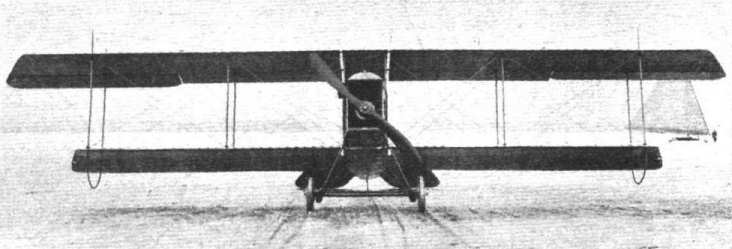
Front view of the M.F.P. model B 2 biplane.
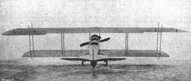
Rear view of the M.F.P. model B 2 biplane.
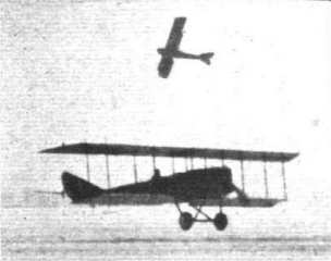
Two views of the M.F.P. biplane in flight.

THE M.F.P. MODEL B 2 BIPLANE - Three views showing the construction of the fuselage and main planes.
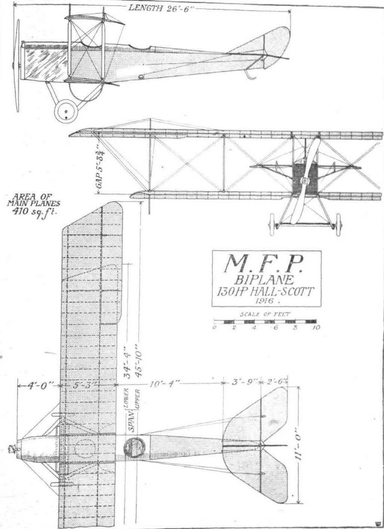
THE M.F.P. MODEL B 2 BIPLANE. - Plan, side and front elevation to scale.
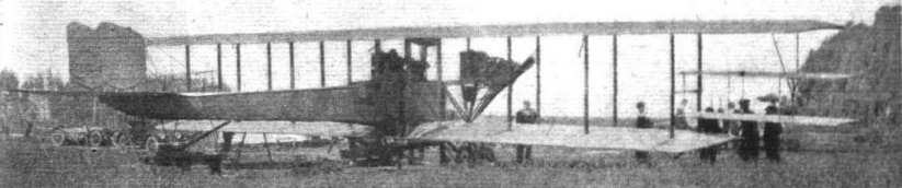
A new twin-engined "battleplane," intended, it is stated, for the U.S. Army, has just been completed at Sunnyvale, California. As the photograph shows, it is of the fuselage tractor type, with the engines mounted on the wings. The machine weighs about two tons, and has a span of 72 ft. and an overall length of 40 ft. It is expected that she will carry nine or ten passengers. A pecularity of this machine is the biplane type of ailerons, which can be seen in the illustration.
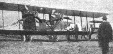
A closer view of the two engines of the new American "battleplane." Each of these is of 120 h.p. The mounting, It will be noticed, is of a somewhat unusual form, and does not look any too strong, while apparently offering a fair amount of resistance.
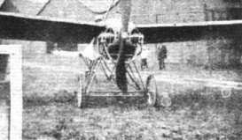
THE ASHMUSEN AEROMOTORS IN ACTIVE SERVICE. - The Antonelli monoplane with 8-cyl. plant.
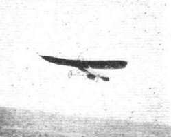
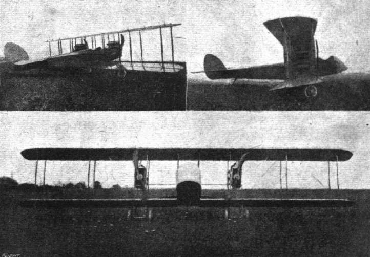
THE LATEST ANfERICAN "TWIN" BATTLEPLANE. - Built by the Atlantic Aircraft Co., it has a span of 48 ft., and a supporting area of 550 sq. ft. The chord and gap are 6 ft. and 7 ft. respectively, and the length is 28 ft. 6 3/4 ins. Two 90 h.p. Aeromarine engines are installed, and the speed range is 50-85 m.p.h.
Flight, April 13, 1916.
THE BENOIST FLYING BOAT.
MODEL "C" TWIN ENGINED.
So successful has been the passenger air service between Petersburg and Tampa, Fla. (about 20 miles), which was inaugurated on January 1st, 1914, by the Benoist Aeroplane Co., that it has been found necessary to design a 'bus capable of carrying a larger number of passengers than did the standard Benoist flying boats originally used. Hence the large twin-engined flying boat, shown in the accompanying illustrations and scale drawings, and it must be admitted that its designer, Tom W. Benoist, has succeeded in producing a decidedly interesting machine of a type that is bristling with "knotty" problems. He has, furthermore, met with results in actual practice that have been extremely encouraging.
In the design and construction of the model "C" flying boat the usual Benoist practice obtains almost throughout, the only departures being those necessitated by the peculiarities of twin engine design and the large size of the machine. For instance, the power plant, which in this case consists of two 100 h.p. Roberts motors, is not located in the hull, as has always been a feature of previous models, but is arranged between the top and bottom planes. The boat is of the short hull type, as in previous Benoist models, though somewhat modified, the "business" portion of the boat finishing just aft of the main planes, the remainder of the boa merely serving to carry the tail. The length of the boat proper is 20 ft. 6 ins., and the beam is 5 ft. 6 ins , whilst the maximum depth of the hull is 3 ft. The step is located 13 ft. 6 ins. from the nose, being rather further back than is usually found in other designs of flying boats, viz., at the cg. of the machine. From the stern up to a point about 7 ft. from the nose the bottom is flat, after which it is slightly V-shaped laterally and curved upwards. From the nose to the cockpit is an inverted V deck. The cockpit is very roomy, measuring 5 ft. fore and aft, and seating six persons - three, including the pilot, in front and three behind. The latter seats are immediately in front of the main planes, so that all the occupants have an excellent view in all directions. The hull is built up in the usual way of first-grade clear mahogany, the sides being 3/8 of an inch thick, and the bottom consisting of two layers of the same thickness, except for the last five feet at the stern, which is made up of a single layer. The rear portion of the boat carrying the tail planes is to all intents and purposes a fuselage of rectangular section attached to the stern of the boat proper and sloping upwards. It is built up of four longitudinals and six sets of cross members, the whole being wire-braced and covered with fabric.
The main planes, which have a span, top and bottom, of 65 ft., are a development of those employed on preceding models, modified as to camber and construction to meet the special requirements of a machine of this type. They are made up of five sections as follows: A centre section 11 ft. span rigidly attached to the boat and carrying the two engines. Attached to the centre section are inner extensions measuring 14 ft. 6 ins., and to these are attached the outer extensions of 12 ft. 6 ins. In the centre section and the inner extensions the main spars are of spruce, with a cross section of 2 by 2 1/2 ins., and in the outer extensions they have a cross section of 2 by 1 1/2 ins. A "V" arrangement is employed for the interplane struts in the centre or boat section, which has the advantage not only of being extremely strong and rigid, but the absence of bracing wires between the two pairs of innermost struts allows a clear passage from the cockpit to the stern of the boat and to the engines, which can thus be inspected with the greatest facility. This arrangement also provides exceedingly strong and simple mounting for the engines, the cross pieces of the "A's" formed by each of the two outer pairs of centre section struts carrying the stout engine bearers. In front of each engine is mounted a square radiator through which projects an extension of the crankshaft for receiving the crank-handles for starting the engines. From the centre section outwards top and bottom planes are separated by four pairs of stout streamlined struts having a factor of safety of about eight or ten. The lower plane is set at a dihedral angle, the gap being 6 ft. at the centre and 5 ft. at the wing tips. This not only makes for stability, but enables the lower wing tips to be kept as far as possible out of the water, which is a matter of some importance with big span machines. Bracing is by Roebling 19-strand cable, the positive or carrying wires of the inner box section being 8/16 in. doubled and 8/16 in. single for the outer box sections. A neat method of attaching the cables to the turnbuckles, anchors, &c, is employed. Small brass ferrules are slipped over the cables when turned back to make the loop and soldered in place. The end of the cable opposite the turnbuckle is looped but not soldered or fastened permanently in the eyelet of the fitting, and the latter is provided with a small bolt which can be withdrawn by removing a cotter pin, it being thereby possible to make up all the cables on the bench and attach them in an instant, as well as to carry a supply of spare cables on board. All the wing fittings are made of sheet steel stampings spot welded where necessary, and the planes are covered with strong unbleached Irish linen treated with five coats of special Benoist dope and finished with two coats of Valspar.
Ailerons are hinged to the rear spar extremities of the top plane only, and floats are mounted under the lower plane just below the extreme outer inter-plane struts. A Dep. type of control is fitted, but any other system can be installed. The fuel tank, which has a capacity of about 30 gallons of petrol, is located in the boat immediately behind the cockpit As previously mentioned, two 6-cyl. Roberts two-stroke motors of 100 h.p. each are fitted, being coupled direct to 8 ft. 6 in. diameter by 5 ft. 6 in. pitch propellers revolving in opposite directions at 1,100 r.p.m.
The principal characteristics of the model "C" Benoist flying boat are :- Span, 65 ft.; Chord, 5 ft. 6 ins.; gap, 6 ft. to 5 ft. ; supporting area, 660 1/4 sq. ft.; weight empty, 2,400 lbs.; useful load, 1,300 lbs.; speed range, 40-60 m.p.h.; climbing speed, 500 ft. per min.
The Benoist machines have now acquired considerable interest for us in this country, as Messrs. R. F. Wells and Co., of 10, Elystan Street, Chelsea, have recently arranged for the British agency and to build them under licence.
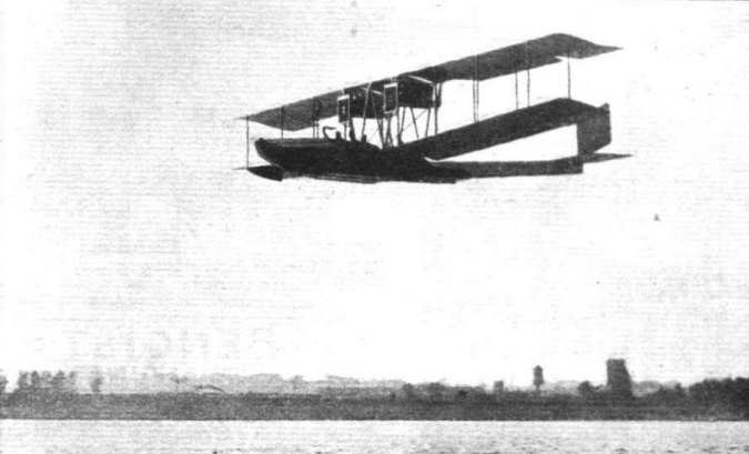
The model "C" Benoist twin-engined flying boat in flight.
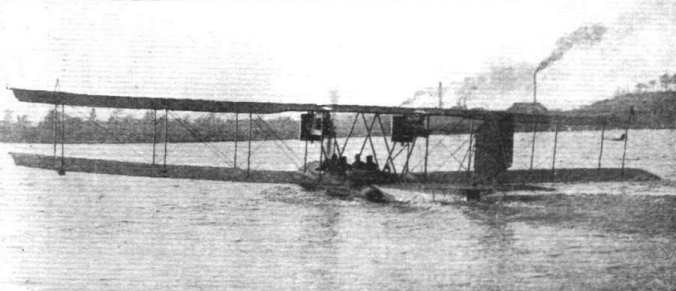
Three-quarter rear view of the model "C" Benoist twin-engined flying boat.

View showing the boat and engines of the model "C" Benoist flying boat.
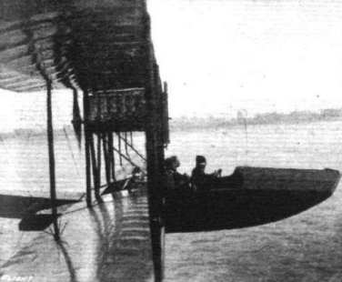
A passenger on the new Benoist flying boat takes a photo, of the cockpit and its occupants whilst in flight.
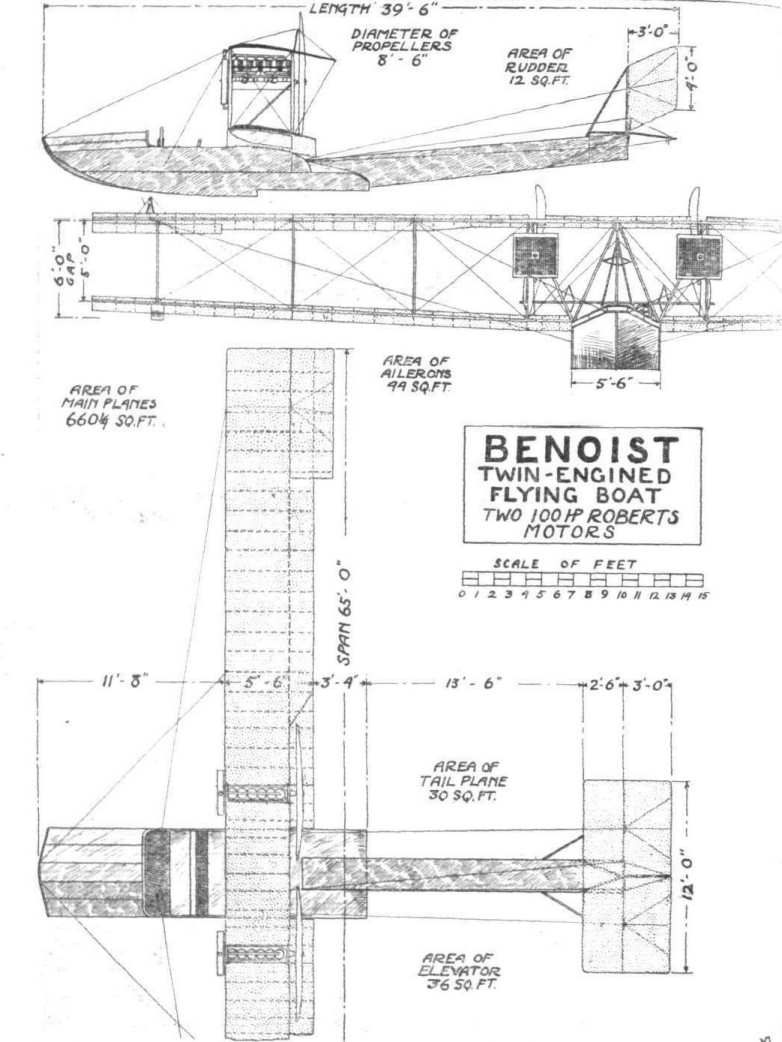
THE MODEL "C" BENOIST TWIN-ENGINED FLYING BOAT. - Plan, side and front elevation to scale.
Flight, November 23, 1916.
THE BURANELLI-CARISI "PUSHER" BIPLANE.
SEEING that America has not done very much in the way of "pusher" biplanes of the headless nacelle type, and inasmuch as the gun 'bus is claiming no small amount of attention from designers at the present moment, special interest attaches to the machine, recently designed in America, illustrated in the accompanying scale drawings. This machine has been jointly designed by Mr. Vincent J. Buranelli and Mr. John Carisi, and was built some little time back in New York.
Although the Buranelli-Carisi, or "A.B.C." biplane, as it is named for the sake of brevity, might be said to belong to the Henry Farman type of biplane, it really differs from it in some of the essential features, i.e., the main planes are swept back, the top plane has a considerable overhang, and only one pair of interplane struts on either side of the nacelle separate top and bottom planes. There are, of course, other less radical differences in minor details.
The top plane has a span of 40 ft. and a chord of 5 ft. 6 ins., whilst the lower plane has a span of 22 ft. and a chord of 4 ft. 6 ins., and both are swept back 10°. The trailing edges of both top and bottom planes are in line, thus giving the effect of staggering the planes. The planes are divided into five sections, two lower and three upper. The lower plane sections are mounted direct on to the nacelle, whilst the two innermost sections of the upper plane are anchored to two inverted V pylons of spruce struts mounted on the nacelle. All the mountings of these different sections are of the hinged quick detachable type, facilitating transport. The upper plane extensions measure some 12 ft. each, being braced by Roebling cable of 4,000 lb. tensile strain from pylons mounted on the extremities of the inner plane-sections above the interplane struts. A rather unusual feature for a machine of this type is that lateral balance is maintained by warping the top-plane extensions instead of employing ailerons.
The planes are built up on solid I section spars with built-up ribs of similar section. The front spar of the upper plane is situated close to the leading edge, and the rear spar some distance from the trailing edge, whilst in the lower plane the front spar, which like the rear spar is of substantial width, forms the leading edge itself. Both top and bottom planes are wire braced between the spars, and Irish linen doped with Emaillite is used for the covering. The interplane struts, of spruce, are exceptionally strong and well streamlined. A wing-section giving high speed and maximum lift is employed.
The tail planes are similar in form to those on the Henry Farman, being carried in the same way by four outriggers of 1 1/8-in. steel tubing with wood struts, vertical and horizontal. The forward ends of the top outriggers are attached to the top of the upper plane rear spar, just above the interplane strut, and the rear ends come to a point at the vertical post to which the rudder is pivoted. The latter, it will be seen, is slightly staggered forward, somewhat on similar lines to the first Vickers gun-'bus exhibited at the 1913 Olympia Show. The lower outriggers are similarly mounted on the lower plane. The horizontal stabilising plane is mounted on the top outriggers, and has an area of 27 sq. ft. The elevators, measuring 2 ft. by 5 ft., are hinged to the trailing edge of the stabilising plane, one on either side of the rudder, which is of 10 sq. ft. area and partly balanced. The attachment of the stabilising plane is by special fittings which allow different angles of incidence to be made. The construction of the various tail surfaces follows that of the main planes.
The nacelle is deep and roomy, and well streamlined. It is built up of stout longitudinals, and struts, in such a manner that they serve as bracing members, thereby dispensing with wire bracing. It is about 10 ft. in length, 3 ft. wide and 3 ft. 6 ins. maximum depth. The engine is mounted on strong ash bearers at the rear. The nose of the nacelle is formed by the radiator, which is of the pointed or "Metallurgique" type. Behind are the pilot's and passenger's seats arranged side by side, in front of which is provision for mounting two machine guns. The nacelle is covered with Duralumin throughout Formed integral with the nacelle, the fuel tank has a capacity of 40 gallons of petrol, which is force-fed to the engine. The latter is of 100 h.p., having four vertical cylinders, and has been designed by Mr. Buranelli and Mr. Carisi on the lines of the Austro-Daimler engines.
The landing chassis is of the four-wheel type, and appears to be exceptionally strong. The two main wheels, measuring 26 ins. by 4 ins., are mounted under the lower plane, being supported in two stout struts by rubber shock absorbers. Two skids, each connected to the nacelle by a second pair of struts, extend from the main wheels, and carry at their forward extremities the two smaller wheels which prevent the machine from turning over on its nose in the event of a bad landing. Both pairs of wheels are mounted on tubular axles, and the skids are connected by a cross strut, which, together with the wire bracing considerably strengthens the undercarriage.
The control is on Nieuport lines, a wheel, operating the rudder, mounted on a rocking column which operates the elevators, whilst warping is effected by a foot bar.
The calculated speed is given as 40 to 70 m.p.h., and some promising results should be forthcoming from this machine.
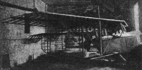
The 100 h.p. Buranelli-Carisi pusher biplane in course of construction..

THE 100 H.P, BURANELLI-CARISI PUSHER BIPLANE. - Plan, side and front elevation to scale.
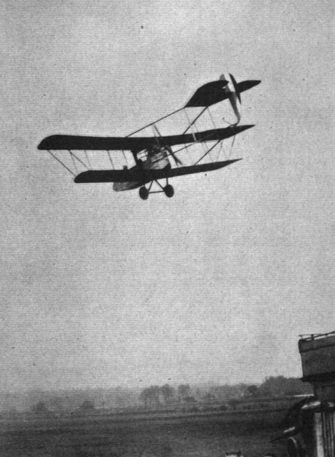
The Burgess machine in flight at Hendon.
Flight, July 20, 1916.
THE C.E. TRANSCONTINENTAL TRIPLANE.
WITH the coming of the large-sized aeroplane the question of multiplanes at once suggests itself as being a means of overcoming many of the problems involved. Apart from the obvious advantages as regards construction and weight-saving this arrangement of lifting surfaces offers, there is, we believe, much to be gained aerodynamically. Since the early, and by no means unsuccessful, efforts of A. V. Roe, little has been done in the way of triplanes, or machines having a greater number of lifting surfaces, and it is only recently that designers appear to be turning their attention in this direction. An interesting example of one of these efforts is to be found in the large C.E. Transcontinental triplane built at Anderson, Ind., U.S.A., some particulars of which have appeared in our American contemporary, Aerial Age. Although this machine is essentially a large one, having over 1,000 sq. ft. of lifting surface, it will be seen from the accompanying scale drawings that by virtue of the arrangement of the planes the overall dimensions are by no means abnormal, the length being 32 ft. 6 ins., and the span 59 ft. It has been designed for use over both land and water, a four-wheeled running gear being fitted to the boat-like body. The latter consists of a rectangular fuselage constructed of ash and spruce longitudinals and struts, which tapers to a horizontal knife-edge at the rear and to a point at the front. The whole body is strongly wire braced, and is given a streamline shape by means of formers and stringers, and a covering of three-ply spruce and a single layer of specially treated cloth. Provision is made for eight passengers, who are totally enclosed by the body, vision being obtained by means of windows.
The most interesting feature in the design of this machine, however, is to be found in the main planes. It will be noticed that the gap is exceptionally small in comparison with the chord - far too small, we should say, to get the best results from the planes. The wing-section employed is that of Kauffman (Eiffel No. 37), which compares favourably with the best wing-sections of to-day. It is doubtful, however, if the designers of the C.E. triplane have taken full advantage of its characteristics, for apart from the question of the small gap previously referred to, the normal angle of incidence given (8') does not appear to be the best under the circumstances. A section of the wing used on the C.E. triplane with dimensions is shown in one of the accompanying illustrations, whilst the general characteristics of a similar model section tested at the Eiffel Laboratory are also given. The planes are built up on two main tubular steel spars with 3/4 spruce battens nailed and glued to hollow laminated birch and mahogany webs. Some 2 ft. 4 ins. from the trailing edge is a third spar. The interplane struts are arranged in sets of three - a strut from each spar - in all, eight sets or 24 struts between each plane. In the centre the top and middle planes are supported by two sets of struts each, the lower ones being mounted on the body, to which the lower plane is attached direct. Level with the middle plane, one on either side of the body, are the two engines, 8-cylinder 140 h.p. turtevants. These are housed in streamlined laminated wood nacelles, each of which carries a passenger - presumably to look after the engine. Located in each of these nacelles is a 30 gallon fuel tank, fed from the six 40-gallon tanks located in the body of the machine by a special vacuum-feed system. The engines are coupled direct to tractor screws about 10 ft. in diameter. Ailerons are hinged to the extremities of the top and middle planes only, and a stabilising plane of some 43 sq. ft. area is mounted above the stern of the body slightly below the line of thrust. Hinged to the trailing edge of the tail plane is the elevator, which is divided into three by the two partly balanced rudders. Both elevator and rudder controls, as well as that of the ailerons, are incorporated in one operating column.
It is intended to build a second machine after the first one has gone through its air tests, and in this second machine steel will be used practically throughout. The principal characteristics of the first C.E. triplane are as follows:-
Span, 59 ft.; chord, 6 ft. 6 ins.; gap, 4 ft.; area of main planes, 1,650 sq. ft.; overall length, 32 ft. 6 ins.; weight complete, 5,500 lbs.; speed range (calculated), 48-98 m.p.h.; climbing speed, 900 ft. per min.; petrol capacity, 300 gallons.
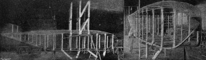
Two views of the body of the C.E. Transcontinental trlplane in course of construction.
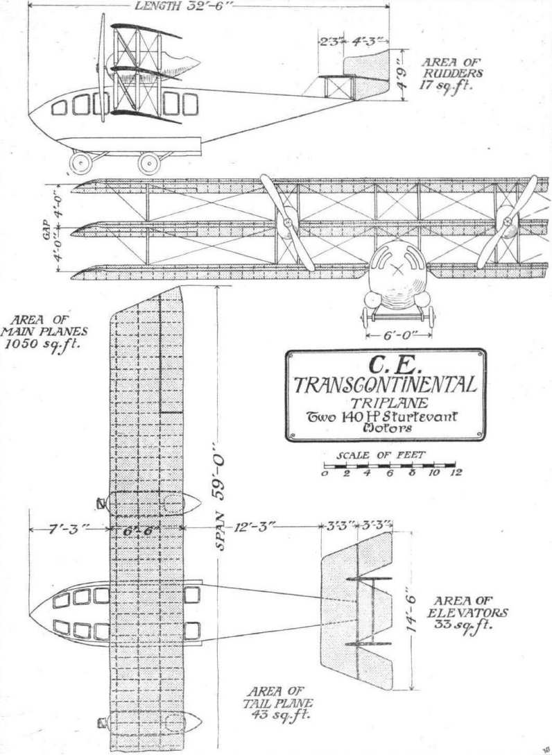
THE C.E. TRANSCONTINENTAL TRIPLANE. - Plan, side and front elevation to scale.
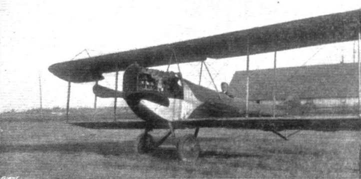
ONE OF THE LATEST CHRISTOFFERSON TRACTOR BIPLANES FITTED WITH 125 H.P. HALL-SCOTT MOTOR. - The Chinese Government has placed an order for 25 similar machines.
Flight, April 6, 1916.
LAUNCHING SEAPLANES FROM BATTLESHIPS.
THE U.S. NAVY METHOD.
SINCE the days when a Curtiss hydro-aeroplane first left the deck of a battleship the problem of starting from and lighting on a man-of-war has received great attention both in America and other countries. While under favourable conditions it has been possible for one of the old-type slow seaplanes to alight on the deck of a ship the difficulties of so doing are very great, and it has become general practice to let seaplanes alight on the sea, to be hoisted on board afterwards. As regards starting from the deck of a ship, one of the difficulties is that of providing a sufficiently long platform to allow the seaplane to gather sufficient velocity to sustain it when it has left the launching platform. For the following description of how this is accomplished in the U.S. Navy we are indebted to our contemporary Scientific American:-
"The seaplane as a naval scout should be able to operate from a moving ship as a base, and to do this with much the same indifference to the state of the weather as its fellow in the military service, starting aloft from the ground. Otherwise its nautical usefulness would in no way be comparable with that so splendidly discharged by aircraft in the army. The stumbling block has been very largely the seaplane's inability to get a start from rough waters. The sturdiest of them are able to land upon something-of a troubled sea but their pontoons do not permit them to gain sufficient speed under those circumstances to insure the take-off for a flight. Therefore, even though they might be put overboard safely in the lee of a ship it has not been possible, except under the most favourable conditions of the water, to get them away in flight.
"But this difficulty has been surmounted here, thanks to the initial work of Captain Washington I, Chambers, U.S.N., who gave us the idea of a catapult launching apparatus for naval aircraft. As a practical naval man, this officer realised that no fighting ship could afford to be encumbered with long launching platforms such as were tried first here and then experimented with abroad. He knew that space must be economised and the sweep of guns uninterrupted. Therefore he conceived a short-run catapulting railway that could be quickly erected and just as rapidly dismantled and stored away. His first apparatus was tested over three years ago at the Washington Navy Yard, and as an outcome of those promising experiments a new machine was designed and sent to the Aeronautic Station, Pensacola, Florida.
"There it was installed at the start upon a coal barge and thoroughly tried out. As a result of its success the apparatus was removed and placed permanently aboard the U.S.S. 'North Carolina.' It is from this ship that seaplanes have repeatedly been launched in the past few weeks in the open sea and with the armoured cruiser underway. Despite the fact that one of the older and heaviest of the service aeroplanes has been used in these trials, still the catapult has answered admirably and has taken care of the load imposed upon it again and again. This point is suggestive, because the weight factor may be taken to represent either a long-range scout or a lighter seaplane equipped with bomb-dropping apparatus.
"In principle, the launching device consists fundamentally of a car propelled along a narrow-gauge track. Upon this car rests the seaplane, and the aircraft is secured to the vehicle until the latter reaches the end of the runway. When the car stops the seaplane is automatically released, and the acquired inertia suffices to sustain the flying machine until its propellers are able to provide the necessary propulsive effort. As a rule, however, the aircraft's motors will be speeded up to this point by the time the end of the track is reached. The method of operating is as follows: The plane is lifted on to the car and secured to it, then the motors are set going but not at full speed. This is accelerated after the catapulting begins. The aviator takes his seat in his craft, and when everything is in readiness the car, with its load, is drawn along the track at an increasing rate. This gathering momentum is so nicely controlled that a velocity of about 50 miles an hour is attained by the time the aeroplane is cast loose from the car. The car is brought to a standstill a very few seconds later.
"Originally, the truck was sent overboard at the end of its run, but in service aboard a ship underway at sea this would be undesirable, because it would be necessary either to stop or slacken speed in order to haul the car aboard even if it were held by a line. Clearly it would be impracticable to abandon the truck and to hold in reserve any number of them. The motive power employed for moving and speeding up the catapult car is compressed air. By means of a throttle worked by a cam, the air impulse is progressively increased upon the operative piston or plunger which functions the wire rope purchase by which the truck is pulled during its comparatively short run of something less than 50 feet. The actual stroke of the piston is in the neighbourhood of one inch for each foot of advance on the part of the truck; the turns of the wire rope over pulleys serving to produce this multiplication of movement. The air required by the catapult is supplied from the torpedo air service of the cruiser and at a pressure of something like 300 pounds per square inch.
"The runway is made up of light steel angle iron and raised only three feet or so above the ship's deck, to which the structure is secured by attachments that can be quickly released when it is desired to dismount the apparatus. The aviator is not jarred during the acceleration of the car and the final catapulting of the seaplane. The only sensation on the part of the pilot is like that due to a sudden blast of air in the face. The trials so far have been conducted with the 'North Carolina' steaming along at cruising speed.
"A scout cruiser is capable of covering a visual front of but 20 miles under favorable conditions of the atmosphere. An air scout 4,000 feet aloft can observe ships 70 miles away! There is no need of elaborating upon the strategic advantage obtained by the use of scouting seaplanes. It is just this widened field of observation which the aeroplane catapult makes possible."
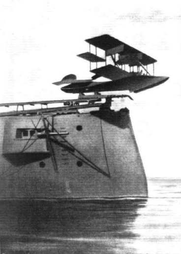
Launching a seaplane from the deck of the U.S. armoured cruiser "North Carolina".

THE ASHMUSEN AEROMOTORS IN ACTIVE SERVICE. - View of the Stephens flying boat with 12-cyl. plant.
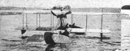
THE ASHMUSEN AEROMOTORS IN ACTIVE SERVICE. - View of the Stephens flying boat with 12-cyl. plant.
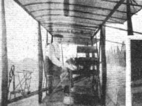
THE ASHMUSEN AEROMOTORS IN ACTIVE SERVICE. - The original 8-cyI. plant installed in a Curtiss-type pusher biplane.
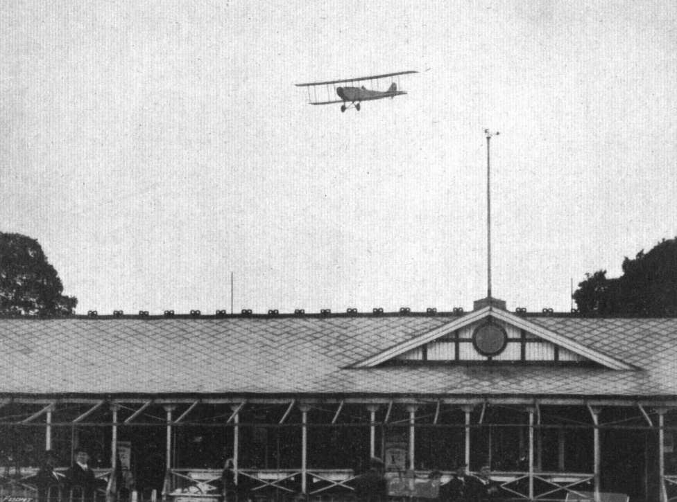
A finishing glide at Hendon Aerodrome by Mr. Sydney Pickles, on one of the Curtiss machines.
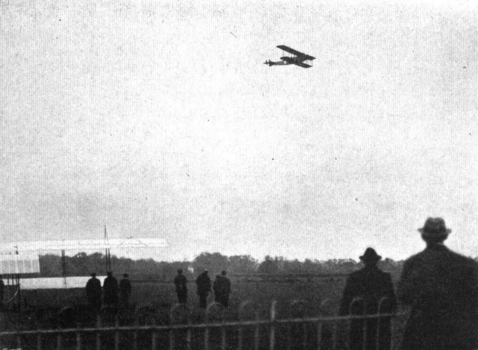
Mr. Sydney Pickles flying a Curtiss at Hendon Aerodrome.
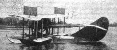
A Curtlss flying boat of the "Super America" type, presented by Mr. Glenn Curtiss to the American Coast Guard, who will employ it for "spotting" and reporting the location of derelicts.
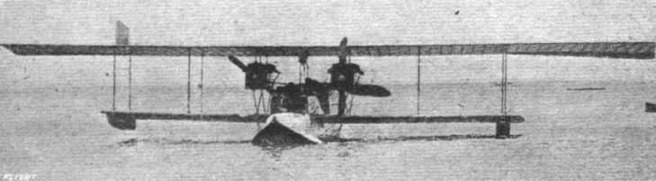
Front view of the Curtlss "Super America" flying boat, which carried eight passengers during her trial tests at Newport News, Virginia.
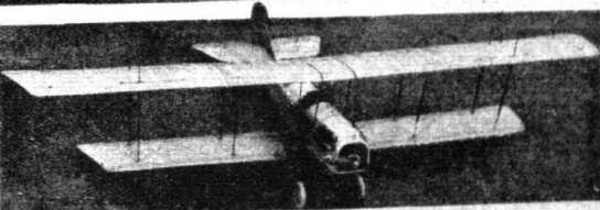
The military two-seater tractor equipped with a 160 h.p. engine at the Atlantic Coast Aeronautical Station at Newport News, Virginia.
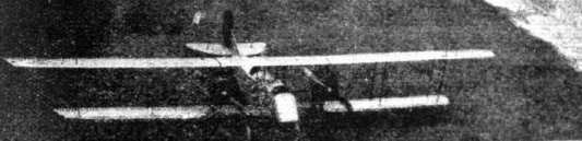
The large biplane is one of the new twin engine machines, fitted with two 160 h.p. motors at the Atlantic Coast Aeronautical Station at Newport News, Virginia.
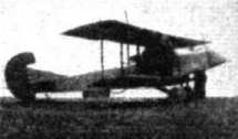
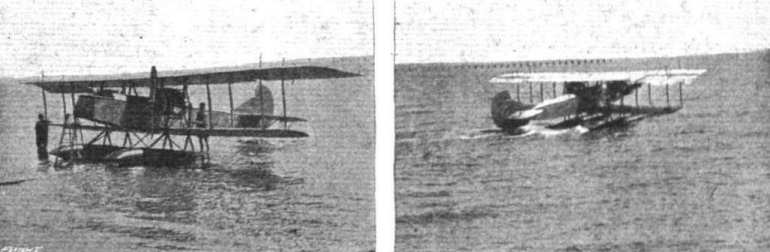
THE CURTISS TWIN-ENGINE HYDROBIPLANE. - On this machine Victor Carlstrom, on August 25th last, put up a new American distance record, flying a circular route between Newport News and Cape Charles of 661 miles in 8 hrs. 41 mins. The weather was bad, and he carried as passenger a mechanic, whose services, however, were not called upon throughout the trip.
Flight, September 7, 1916.
A NEW CURTISS "WIRELESS" SCOUT.
ON August 9th some very interesting trials were carried out at the Curtiss Aerodrome, Buffalo, N.Y., when Victor Carlstrom, the well-known Curtiss pilot, put the new Curtiss model S-2 "wireless" scout through her paces. Equipped with a 100 h.p. Curtiss engine, the machine made a speed of 119 m.p.h. over a measured course. This is claimed to be a world's record for speed with an engine of this power.
As regards the body, the new scout, it will be seen, is very similar to the previous type Curtiss scout, but several alterations are noticeable in the arrangement of the main planes. In the first place, the lower wing is of quite short span, and a single strut on each side connects it to the upper wing. This strut is spread out at its upper and lower ends so as to take care of the travel of the centre of pressure for various attitudes of the wing. No external wire bracing of any kind is employed in the wing structure, the single strut effecting all the trussing. The undercarriage is also of an unusual type. In addition to the usual "V" chassis, there are struts sloping backwards and outwards from the axle to the lower wing spars at the point where is attached the inter-plane struts. When the machine is in the air, these struts, it will be seen, are working in tension, thus partly taking the place of the usual lift wires. Some slight "cleaning up" changes in the design including an annular conical stream-lined casing over the boss of the tractor screw, are being made which will, it is anticipated, increase the speed of the machine to about 125 m.p.h. The span of top plane is 21 ft. 10 ins., and bottom plane 11 ft. 3 ins.

The "baby" tractor has a span of about 20 ft. and is expected to develop a speed of somewhere in the neiborghood of 100 m.p.h. At the Atlantic Coast Aeronautical Station at Newport News, Virginia.
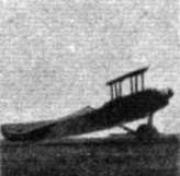

Three-quarter rear view and three-quarter front view of the new Curtiss "wireless" scout.
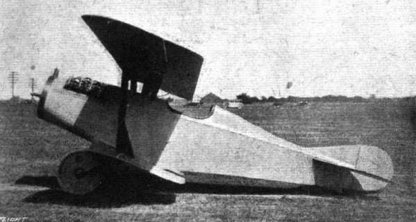
Side view of the Curtiss (Type S-2) "wireless" scout.
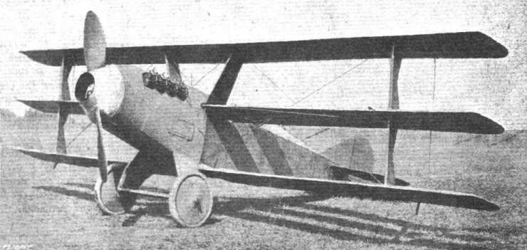
The latest Curtiss speed scout - a triplane - four of which have been ordered by the U.S. Army. Briefly, the dimensions are: Span, 25 ft.; overall length, 18 ft.; chord, 24 ins.; gap, 28 ins.; gross weight with fuel and water, 1,060 lbs.; speed, 120 m.p.h.; climb, 10,000 ft. in 10 mins. It is fitted with a Curtiss OXX-2 motor, streamline wiring is used throughout, and the shock-absorbers are also streamlined.
Flight, January 13, 1916.
A FIGHTING FLYING BOAT.
NOT only is there a great deal of time and thought being given to the production of large fighting aeroplanes in this country, but in America the problem is being strongly attacked. Thus the Curtiss Company are building a huge triplane flying boat of which the following particulars have been given by the Scientific American:-
"This machine, which can properly be called the first battleship aeroplane, is a direct development of the 'America,' a twin-engine flying boat which was to cross the Atlantic in the summer of 1914, when the outbreak of the war stopped the attempt.
"The Curtiss 'battleship-aeroplane' is a triple-screw triplane flying boat, which will weigh, fully equipped, 21,450 lbs.
"The hull is of cedar planking, sheathed with copper on the under side, and riveted to stout ash ribs: it is 68 ft. long, and has a beam of 20 ft. The hydro-planing surface of the hull is furnished with a V-shaped bottom, which ends in a straight stem forward, while its rear, cut off sharply, gives the 'step,' on which the boat must ride in order to get off the sea. From the step on the hull it has straight side lines, and tapers gently towards the stern, to end with a water-rudder.
"The hull is divided into twelve water-tight compartments, one-third of which are supposed to keep the machine floating, should the hull be pierced and several compartments be flooded.
"The inner arrangement of the boat consists (1) of a conning tower containing the controls and the navigating instruments, and (2) of a cabin, fitted as quarters for a crew of eight, and containing the fuel tanks, ammunition and stores.
"The boat is steered from the conning tower; when riding a rough sea the latter can be hermetically closed against the spray. The fuel tanks contain 700 gallons of gasoline and 80 gallons of oil; this will give the machine (at a speed of 75 miles per hour) a cruising radius of 675 miles. This could be considerably increased by fitting additional tanks, in which case the military load (guns, bombs, &c), would have to be decreased. The superstructure of this battleship aeroplane consists of (1) the supporting planes, (2) the propelling apparatus, and (3) the steering organs.
"There are three superposed supporting planes, each having a span of 133 feet and a chord of 10 feet, with a gap of 10 feet between each plane; the total area of support amounting to about 4,000 square feet. The weight of the hull and of the supporting planes amounts to about 12,000 lbs. As customary on marine aeroplanes, the tip of each lower wing is fitted with a pontoon, which prevents the wing from digging into the water when running on the surface or when at anchor.
"Just like the 'America,' which revolutionised aircraft construction with her twin engines, the latest product of the Curtiss yards marks again a new departure in the arrangement of the propelling apparatus. The latter consists of six 160 h.p. water-cooled V-type engines, which are coupled in twin units of 320 h.p., each unit driving an air-screw about 15 feet long. But while one of these twin units is placed amidship and drives a central pusher screw, the two other units are mounted on the leading edge of the centre plane on either side and above the cabin, and each drives a tractor air-screw.
"An auxiliary engine of 40 h.p. enables the pilot to start these engines from the conning tower by means of an electric starter. This engine is also used for generating the current required by the automatic stabiliser, the drift indicator and the minor apparatus. Finally, for water navigation, the auxiliary engine also drives a water propeller.
"Aside from the truly gigantic dimensions of this machine, the disposition of her power plant marks a notable advance in aircraft construction.
"If in an ordinary aeroplane the engine fails, the airman has to glide down to earth in order to effect repairs. In the twin-screw flying boats of the 'America' class this contingency arises just as well, but as long as one engine is kept running, skillful steering will keep the machine on a much longer glide-path, whereby there is much less risk for the pilot to fall into the hands of the enemy.
"But in the new triple-screw flying boat, engine trouble can be dismissed almost entirely as far as the machine's safety is concerned. In fact, each of the three air-screws being actuated by twin engines, the failure of one or two of the engines will only result in reducing the flying speed; and, owing to the great inertia of the machine, a mechanic can easily climb on a ladder to the defaulting engine and promptly repair it without impairing the lateral stability. And, taking it at its worst, should both of the twin engines, which drive the tractor-screws, break down, the engine unit actuating the pusher-screw (320 h.p.) would still give the boat a very wide gliding ratio, about 15 in 1, in the course of which there still would be time to repair the defaulting engines or else to choose the best possible landing place.
"This feature of the new flying boat makes her particularly desirable for military and naval work, where long range reconnaissances are always fraught with danger on account of the relative unreliability of flight engines.
"The steering organs placed at the boat's stern consist of a balanced rudder of 54 sq. ft. area, with a keel-fin of 46 sq. ft. area. Longitudinal stability is effected by a non-lifting tail, consisting of a tail-fin of 126 sq. ft. area and of an elevator of 96 sq. ft. area. For transverse stability interconnected ailerons are hinged to the supporting planes.
"Little is known so far as to the armament this flying boat will carry. Whereas the pure military load (outside of crew, instruments and fuel) amounts to about 3,000 lbs., it can be safely assumed that at least two 1 1/2-lb aircraft guns, of the type used on the 'America' class, will be mounted on the forecastle, in addition to which there should be a small battery of machine guns for repelling speed scouts. It is possible, however, that the main armament will comprise a much heavier arm, such as a 3- or even a 6-pound gun, and that there will be a trapdoor in the hull through which the said gun could be fired in all directions, owing to a turret mounting.
"The craft will carry a very complete equipment, such as pneumatic life preservers and cushions, fire extinguishers, anchors, ropes, and possibly a collapsible mast for signalling.
"Altogether, there is no exaggeration in saying that the Curtiss triple-screw flying boat opens a new epoch in aircraft construction; and while far from being an aerial battleship such as may be seen in the future, she certainly represents the embryo of such an idea. In the present war she should prove immensely valuable; for in view of her superior armament, cruising radius and sufficient speed, there does not seem to be anything aloft that could meet her on even terms."
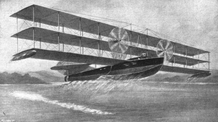
A drawing of the new giant Curtiss fighting seaplane.
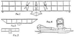
Comparison of the (Fig. 1) new Curtiss fighting seaplane with (2) the America, and (3) the standard Curtiss seaplane. Fig. 4 shows a side elevation of the new seaplane.
Flight, September 21, 1916.
THE FEDERAL PUSHER BIPLANE.
ONE of the latest recruits to the aeronautical industry in America is the Federal Aircraft and Motor Corporation of New York, which has been formed for the purpose, not only of manufacturing machines of various types to their own designs, but with a view of conducting a flying school at New York City. The machines in use for this latter branch include a Curtiss flying boat and a Martin tractor, as well as a 100 h.p. pusher biplane of the Company's own design, which is shown in the accompanying illustrations and scale drawings.
As may be seen, this machine possesses several distinctive features, notably the swept-back planes and the "armoured" stream-line nacelle. The latter is mounted on the top of the lower plane, and is built up of ash, covered with sheet steel, which covering is given a finish of black enamel with vermilion lines. The cockpit, seating pilot and passenger side by side, is just forward of the planes, giving an excellent view, and the seats are upholstered with "lanasilk" cushions, which are capable of sustaining the weight of two men in water, should a forced descent be made on the latter. Two fuel tanks, each having a capacity of 21 gallons, or sufficient for 4 1/2 hours' flight, are fitted one on either side of the engine - a 100 h.p. Curtiss OX - which is mounted in the rear of the nacelle. Roomy lockers are provided under the seats for tools, spares, &c, so that minor repairs or adjustments may be effected on the spot. The radiator is mounted on the top of the nacelle just in front of the engine. It is proposed to instal in future models a new engine with which the Federal Co. have been carrying out extensive tests. The Curtiss shoulder-yoke typo of control is fitted, in which an ingenious arrangement is incorporated whereby dual control for either of the three operations rudder, elevator and ailerons - may be installed separately or all together by the fastening of four nuts and a bolt. By this means the pupil can become accustomed to the controls one at a time.
Top and bottom planes, which have a span of 36 ft., are made up of three panel sections, the centre section measuring 8 ft span and the two outer ones being slightly swept back, and thus giving the machine a certain amount of inherent stability. Each surface is built up of two main spars of specially selected ash and ribs of spruce, the whole framework being braced and covered with Irish linen doped with five coats of aero varnish and three coats of Valspar. Upper and lower surf aces are separated by six pairs of streamlined mahogany struts, the fittings of which - as with all other fittings throughout the machine - being of sheet steel stamped out in one piece. Roebling steel cable is used for the bracing throughout, and quick release connections are used extensively. Ailerons are hinged to the outer extremities of the real spars of both top and bottom planes.
The outriggers carrying the tail are of 1-inch steel tube filled with spruce, the spacing struts being of oval section steel tubing secured to the outriggers by stamped steel clips. The tail planes consist of a nonlifting stabilising surface of about 30 sq. ft., to the trailing edge of which are hinged two elevator flaps of 15 sq. ft. each, and a large rudder hinged to a triangular vertical tin. The landing chassis is of the Farman-Wright type, with a pair of 26 by 4 in. wheels to each skid. It is strongly braced by steel tubing.

THE FEDERAL PUSHER BIPLANE. - Plan, side and front elevation to scale.
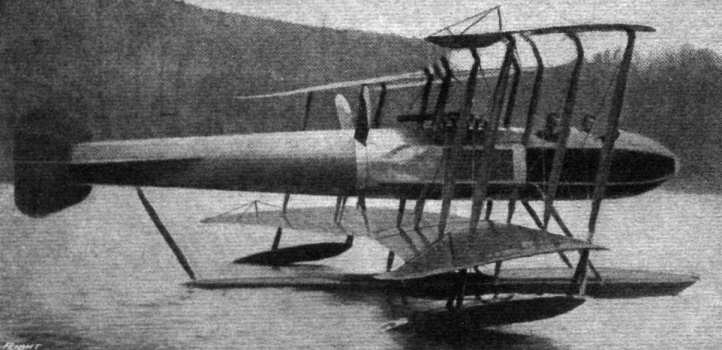
AN INTERESTING EXAMPLE OF A PUSHER FUSELAGE BATTLE SEAPLANE FROM AMERICA - The principal features of this machine, which has been built by the Gallaudet Co. of Norwich, Conn., for the U.S. Navy, consist of the arrow-form wings, and the four-bladed propeller (driven by two 150 h.p. Duesenberg motors) bisecting the fuselage. A clutch connection between each engine and the propeller enables either one or both engines to be used. A speed of 100 m.p.h. is claimed with both engines running, and 70 m.p.h. with one engine. Machines embodying this form of propulsion were designed several years ago by M, Coanda (Bristol), and M. Pateras Peseara, both of which were tested at M. Eiffel's laboratory, whilst other examples are to be found in the Borel and Bleriot pusher monoplanes of 1912-3, and the Grahame-Whlte Military biplane of 1913.
Flight, September 7, 1916.
THE GENERAL AEROPLANE CO.'S FLYING BOAT.
Realising the increasing popularity of the flying boat among sportsmen in the States, more and more of the American manufacturers are turning their activities in that direction. Among others, the General Aeroplane Company, of Detroit, Mich., have recently produced a flying boat that is especially adapted for sporting purposes, and its general lines are shown in the accompanying scale drawing and illustrations. In the "Verville" flying boat, named after its designer, Alfred V. Verville, the Company has aimed at producing a craft embodying the best principles of construction with an efficient design rather than to attempt anything in the way of novelty.
The hull is built up of Honduras mahogany double-planked with aluminium bulkheads forming four watertight compartments, and has a concave vee bottom, with off-sheered deck and D-shaped tail. Aluminium handhole covers are provided, rendering access to various parts of the hull. The cockpit, which seats two side-by-side, is veneered with 1/8 in. Honduras mahogany and upholstered with green leather, filled with "Kapok." The polished mahogany dash-board is equipped with altitude barometer recording to 15,000 ft.; "Tycos" inclinometer; "Tycos" speed indicator; "Tel" revolution indicator; petrol tank pressure gauge, oil pressure gauge, electric light switch, dash-board light, motor cut-out switch, hand throttle and magneto spark control. Four special Tungsten ceils for lighting purposes are provided, and the hand-pump is located in a convenient position for the pilot at the side of cock-pit. The two streamline wing-floats are of mahogany, and have a displacement capacity respectively of 200 lbs.
The main planes are divided into sections, three for the top and two for the lower. The top planes are attached to a centre plane-section - which, it will be observed, is peculiar in that it is arched - supported above the boat by two pairs of struts, whilst the lower plane sections are mounted on the hull.
A highly efficient wing section (Eiffel) suited to the requirements of this type of machine is employed, and the planes are built up in the orthodox way on two main spars with ash compression ribs, and spruce webs and battens. Shelby oval steel tubing is used for the trailing edge, and the whole wing structure is braced with strong Roebling aviator wire. The framework is covered with Irish unbleached linen (having strength in weft of 91 lbs. per linear inch, and in warp of 103 lbs.) doped with nine coats of Emaillite, and surfaced with three coats of spar varnish. The interplane struts are of Virginia silver spruce, well seasoned and shellaced, and bound with grey silk ribbon to relieve shattering. The strut sockets are clamped around wing spars, thus avoiding the necessity of the securing bolts piercing the spars.
Hinged to extremity of top plane rear spar by five cold rolled steel hinges are the ailerons, which are interconnected. Lynite pulleys, having brass bushings throughout, are used for the control gear.
The tail planes consist of a semi-circular stabilizing plane, mounted above the stern of the boat, to which the two elevator flaps are hinged, and a triangular vertical fin, to which the partly-balanced rudder is hinged. Either Deperdussin, Curtiss, or the makers' "three-in-one" systems of control may be fitted.
The engine, a 100 h.p. Curtiss OXX, is mounted above the hull under the top plane centre-section, and drives direct a three-bladed "Paragon" propeller, 8 ft. 3 ins. diam. by 5 ft. 6 ins. pitch, constructed of oak tipped with copper. A flat copper-tube cellular type radiator, in nickel-plated brass casing, and weighing 41 lbs., is mounted in front of the engine. The water capacity is 2 1/2 galls. Starting the engine is accomplished from the cock-pit by means of a crankhandle.
A factor of safety of seven is used throughout the machine. All wiring is doubled (factor of safety taken on one cable), and French "National" turnbuckles are used exclusively; all cable is wrapped with copper wire, sweated with solder and at least three ins. long: control cables are extra flexible 19-strand cotton centre Roebling grade wire. Metal parts are either nickel or treated with non-corroding metal enamel.
The main characteristics are as follows :-
Span: top 38 ft., bottom 30 ft.; gap, 6 ft.; cord, 5 ft.; gliding angle, 1 in 7; length over all, 27 ft. 9 ins.; speed range, fully loaded, 42-70 miles per hour; weight (loaded), 2,050 lbs.; weight (unloaded), 1,450 lbs.

A general view of the General Aeroplane Co's flying boat.

The General Aeroplane Co.'s flying boat taxying on the water.
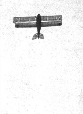
View from below of the General Aeroplane Co.'s flying boat in flight.

THE GENERAL AEROPLANE CO.'S FLYING BOAT. - Plan, front and side elevation to scale.
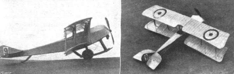
A couple of views of a well-made scale model of the Simolex-Mayo tractor - constructed from the scale drawings in "FLIGHT."
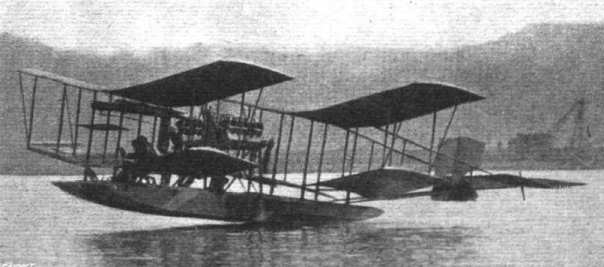
The Richardson tandem-plane, twin-motored hydro-aeropiane being tried near Washington, D.C. Two Robert motors are used. Mr. George A. Gray is the pilot.
Flight, February 17, 1916.
THE SLOANE "H-1" TRACTOR BIPLANE.
THIS aeroplane has been designed and built in America to meet the requirements arising from the present war, for a reliable and speedy tractor capable of carrying a moderate load for a flight of from 4 to 6 hours. In every respect this machine is a great advance over anything previously built by the Sloane Manufacturing Co., of North Avenue, Plainfield, N.J. Great care has been exercised to obtain the most advantageous combination of speed, safety, climbing and weight-carrying possible in a machine of this class, and the designers have somewhat exceeded the usual requirements for strength, so that a factor of safety in excess of seven has been obtained.
Actual tests have shown the flying qualities of this machine to be entirely satisfactory. It is stable and easy to control even in very heavy weather.
The machine is equipped with a six cylinder 125 h.p. Hall-Scott motor, 5 ins. bore and 7 ins. stroke, which has shown itself to be the best motor available for the work required. The wing curve employed is very satisfactory, and has been developed by actual experience and wind tunnel experiments.
The wings of this machine are backswept 10°, and the upper plane is staggered forward 10°, whilst both upper and lower planes are set at a slight dihedral angle.
The main planes are of standard construction, the ribs being built up of basswood, and then slipped over the main beams. The latter are of Alaskan spruce, measuring 2 ins. by 3 ins. and 2 ins. by 2 1/2 ins. front and rear respectively. The trailing edge is steel. The whole is internally braced with cable and wire, and three steel drift braces are located between the beams at strut points. Beams are reinforced so that no wing clip bolts pass through them.
Upper and lower planes are separated by four pairs of streamlined spruce struts, two pairs on either side of the body, and by two pairs of short struts from the body in the centre. The upper planes are attached to a small inner pannel, the same width as the body, and the lower planes are attached direct to the latter. Ailerons are hinged to the extremities of the rear spars of both top and bottom planes. The tail planes consist of a horizontal stabilizing plane, to the trailing edge of which are hinged the elevators. Between the latter is the rudder, in front of which is a vertical triangular fin.
The fuselage is rectangular in section, of streamline form, tapering to a vertical knife edge at the rudder post. The longitudinals are ash and spruce, tapering from 11 in. square to 1 in. square, and the uprights of the same material. Back of the pilot's seat solid wire is used for cross bracing and forward of its cable. Specially designed clamps are used to hold the struts without piercing the longerons. The pilot's and passenger's seats are arranged in tandem, the pilot occupying the rearmost.
The whole nose of the fuselage is enclosed by aluminium, and the cockpits are provided with aluminium covers to protect the passengers. The rest of the fuselage is covered with linen doped and varnished.
The engine is mounted on two ash beams, 2 ins. by 5 ins., which are hung on two hot drawn steel plates, which reinforce the fuselage as well.
The radiators are of the vertical tube type specially designed for the machine, and are mounted one on each side of the fuselage.
The landing chassis is of the two-wheel type. The tubular streamline axle is mounted on two extra heavy laminated U's. Two steel tension and compression members maintain the spacing of these two U's. Four cables stiffen the landing gear so that side strains will not affect it. The usual rubber cord shock absorbers are used in the axle. The axle may be removed without disturbing the rubbers. The tyres are 26 ins. by 4 ins. double tube.
The principal dimensions of the model H-1 Sloane tractor are as follows: Span, 38 ft.; chord, 6 ft. 6 ins.; gap, 6 ft. 3 ins.; overall length, 34 ft.; supporting surface, 510 sq. ft.; speed, fast, 85 m.p.h.; speed, slow, 47 m.p.h.; climb (3,000 ft.), 7 1/4 minutes; load, 1900 lbs.; weight packed for shipment, 4,300 lbs.
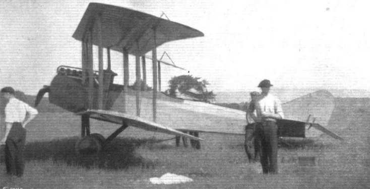
A side view of the Sloane tractor biplane.
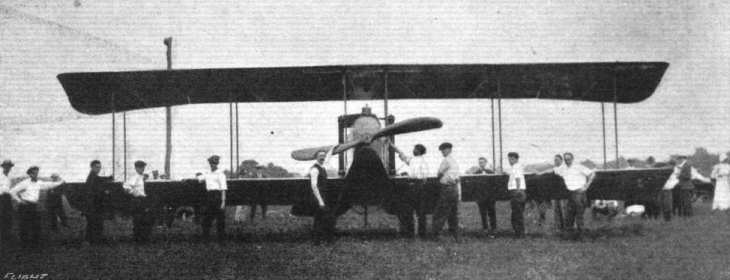
The Sloane tractor biplane from the front.
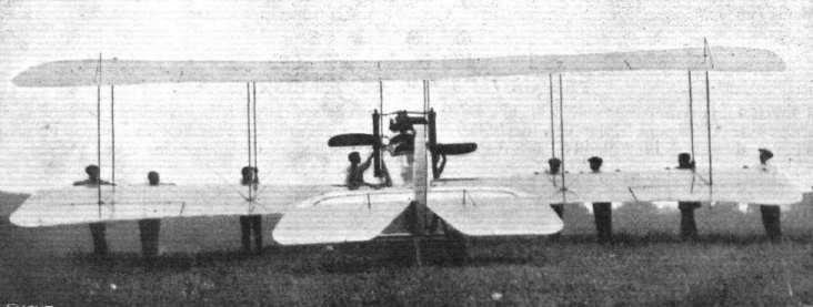
The Sloane tractor biplane as seen from behind.
Flight, January 20, 1916.
AN AMERICAN BATTLE-PLANE.
FURTHER details are now to hand regarding the Sturtevant biplane, of which a photograph appeared in our last issue. From the following details, which are given in our American contemporary Aerial Age, it will be seen that it is proposed to mount two guns, one on each side of the fuselage:-
"On December 12th remarkable flights made at Readville, Mass., by one of the U.S. Army expert aviators, revealed to the public for the first time that a notable development in aviation had quietly been made by the Sturtevant Aeroplane Company under the direction of Mr. Grover C. Loening, B.Sc, M.A., C.E., former Aeronautic Engineer of the U.S. Army, author of 'Military Aeroplanes' and other important technical works.
"As the accompanying illustrations show, the Sturtevant Battle-plane is a biplane of tractor type built with remarkable simplicity and with studied attention to efficiency.
"There are many novel features, including the steel construction, the placing of gun turrets on either side of the central body, the elimination of wires, the general streamline construction which has been carried as far as to having even the cables and turnbuckles in streamline. The span of the machine is 50feet, the length 25 feet; it has a total area of 700 square feet of wing surface.
"It is interesting to note that the machine was completely designed before construction, and extensive aerodynamic tests were made of the model of this machine by Naval Constructor Jerome C. Hunsaker, in charge of the Aeronautical Engineering course at the Massachusetts Institute of Technology, which gave excellent information on the stability and controllability of the machine. Constructed as designed, the machine actually did more than was anticipated.
"In the Sturtevant Battle-plane the single motor tractor that has been puzzling aviation experts is made into a simple effective fighter, by the novel idea of placing a gun turret on either side of the body, as shown in the illustrations, a development which, though obviously simple, nevertheless required considerable effort to work out satisfactorily. These gun turrets, in each of which a gunner observer is located, are placed out on the wings, with an excellent clear view ahead and below and a range for gun fire on all sides, with the added advantage that two guns can be concentrated forward with deadly effect. In addition to that a broadside of both guns can be obtained by tilting the machine laterally, a feature which for a long time escaped attention of aviation experts.
"It is true that in the two motor machines there is a small degree of safety in having one motor still running when the other has been hit, so it is equally true that in the new Sturtevant Battle-plane a gunner is still hitting away when the other has been disabled.
"Due to the better load distribution, the safety factor of this new machine has been shown by tests to be 12 times the flying load. Another feature which is novel is that the gun turrets are readily removable, so that by decreasing the head resistance and the load, the same machine is interchangeable into a high speed, scouting type with great excess power for climbing and cruising radius of over 500 miles.
"Very little data on the performances of this machine are disclosed by the manufacturer, but it is said to have a gasoline capacity of almost 150 gallons, sufficient for 12 hours' flight and to carry a total live load of over 1,200 pounds. The efficiency of this new machine is said to be considerably higher than has been previously attained in this country, due to having all the wires and fittings 'streamlined' (made torpedo shape to reduce head resistance). This, however, is a development that has come to be standard practice abroad.
"It is interesting to note that the gun turrets could be used for carrying mail, and measuring 2 ft. wide by 7 ft. long, they could carry over 24 cub. ft. of mail. One of the most novel features in the construction of this new craft is the use of a new type of vanadium steel construction, lighter than wood, more durable, fireproof, and capable of being extended into aeroplanes ten times the size of this huge bird.
"Several hundred pounds of bombs can be carried on this new fighting flyer, and with its gunners to ward off other aeroplanes, these destructive missiles could be dropped with impunity on a helpless city. There is little doubt that large squadrons of craft of this kind could paralyse a nation's industry, and from what has already been done in Europe, and the indications of what is coming, it is reasonable to predict that the colossal war in Europe will end in the air - in tremendous battles of huge air navies engaged in the destruction of cities, railroads, and even armies.
"While the Sturtevant Battle-plane is but a step in the development of these mighty fleets, it is a remarkable indication of the trend of aeroplane progress, and, more important than all, it has been designed primarily for Uncle Sam."
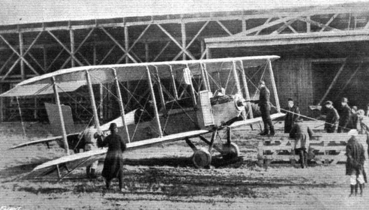
The 140 h.p. Sturtevant-motored tractor biplane, one of America's latest machines. It is somewhat larger than usual, and is of practically all-steel construction.
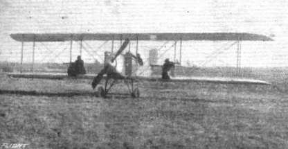
Front view of the Sturtevant Battle biplane showing the gun "turrets" mounted on either side of the body.
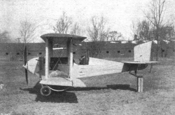
Side view of the new Sturtevant battle-plane, which has accommodation for two gunners on the wings.
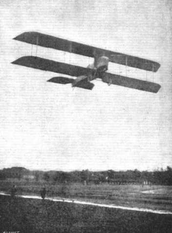
The 140 h.p. Sturtevant Battle biplane in flight.
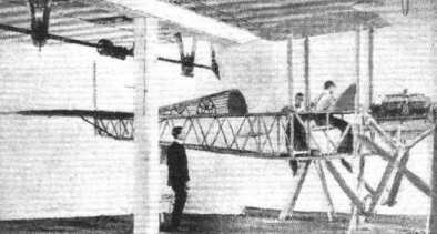
View of the body of the Sturtevant Battle biplane showing the steel construction.
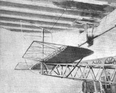
View showing the tail plane and construction of the elevators of the Sturtevant Battle biplane.

The neat attachment of the bracing cables to the interplane strut on the Sturtevant Battle biplane.
Flight, February 24, 1916.
EDDIES.
THE new Thomas military tractor which has been undergoing tests at Ithaca, is, I hear, developing an excellent turn of speed. Not long ago Frank Burnside, one of the Thomas pilots, conducted a series of tests over a measured course of half a mile. The machine covered that distance in 17 4/5 seconds with the wind, and in 29 1/5 seconds against it. The average speed of the tests was one mile in 38 seconds. On one occasion a speed of 103 m.p.h. was attained. The test flights were officially observed by Mr. J. J. Frawley, who is a representative of the Aero Club of America, which body has been notified of the performance. It is claimed that the Thomas has broken all American records for speed. The engine with which this machine is fitted is one of the new Thomas aeromotors of 135 h.p. that have done so well in their preliminary trials.

THE NEW THOMAS MILITARY TRACTOR BIPLANE, TYPE D2. - Fitted with one of the new 135 h.p. Thomas aeromotors, this machine is said to have attained a speed of 102 m.p.h,, which constitutes, it is claimed, an American record.
Frank Burnside poses with the D-2.
Frank Burnside poses with the D-2.
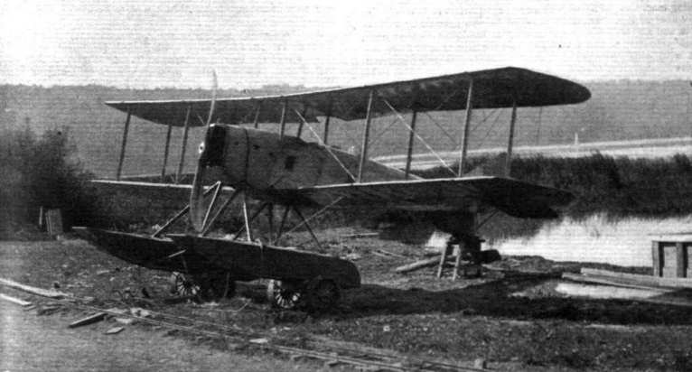
The Thomas seaplane (type H.S.), as being employed by the U.S. Navy at Pensacola, Florida. During tests the average speed developed, with and against the wind, was 82 m.p.h. over a 5-mile course. The machine was piloted by Mr. Frank Burnside, who had with him as passenger and official timer Lieut. Saufly. With the machine fully loaded, the climb was 450 ft. per min, while the gliding angle is stated to have been 1 in 10.2, but the direction of the wind is not stated.
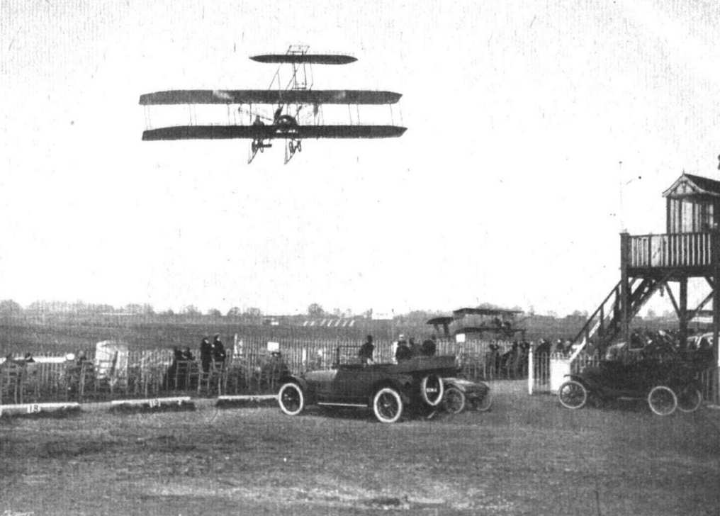
A REMINISCENCE OF HENDON. - Mr. Kenworthy, on a Beatty-Wright, returning to the Aerodrome after executing many thrilling evolutions just out of the range of the camera.
I
I
Flight, August 10, 1916.
THE NEW WRIGHT TRACTOR BIPLANE - TYPE L.
IN general appearance the new Wright tractor does not present anything startling, but follows fairly closely along standard lines. It is designed to combine a fair speed range with reasonable power and low purchase price and cost of upkeep. Its lines do not impress one as being particularly pleasing, and it would appear to have been quite possible to have improved these, considerably without necessarily increasing the cost. However, according to reports the machine flies very well, and after all that is the main consideration.
The main planes are of a totally different section from that of the older Wrights, but no dimensions of the new wing section are available. The top wing is built up in three sections, and the lower in two, the end sections being interchangeable. Bracing is effected by solid wires, all the lift wires being in duplicate. No turnbuckles are employed, the ends of the wires being formed with eyes, securely soldered, which loop over hook plates under the ends of the struts. Instead of having the body struts run to the top rails of the body, as is standard practice on this side, they are connected at the top to a centre section, and at the bottom to a short length of wing secured to the sides of the body. In this way the outer sections of the wings arc easily detachable for purposes of transport. The inter-plane struts are of spruce, streamlined, and fit into sockets with their ends. By taking out a small bolt which runs through the strut and its fatting the struts are slipped out, releasing the wires from the hook-plates. The main wing spars are of spruce, as are also the ribs, which are of I section.
The tail consists of a semi-circular fixed stabiliser, non-lifting, to which the elevator flaps are hinged.
Lateral equilibrium is maintained by double-acting ailerons cut out of both upper and lower planes, hinged to the rear spars. These have a slight curve, and normally are actual portions of the wings. A spruce spacer strut connects the upper and lower ailerons. The control cables run from the spacer strut-ends over pulleys at the upper and lower extremities of the adjacent plane struts and along the wings to the steering column. The cable from the lower aileron runs to the top of the strut and vice versa. The ample surface of the ailerons insures very easy control. The balanced rudder is operated by cables running into and through the fuselage to the "grip" or lever on the steering wheel. The elevator flaps are operated by cables from the masts through the fuselage to the wheel.
The steering set used is the standard Wright system, in which, it will be remembered, that turning the wheel right or left operates the ailerons; rocking the wheel and its supporting column fore and aft operates the elevators. An aluminium hand lever turns the rudder with very little pressure. Gripping the wheel and the lever at the same time in one hand causes the rudder to turn simultaneously with the operation of the ailerons, otherwise the ailerons may be operated entirely independently. The aileron and rudder cables end in short chains which run over sprockets on the steering column. The aileron sprocket is rigidly attached to the axis of the steering wheel. The rudder sprocket is free on the same shaft. Gripping the rudder lever with the wheel in one hand obviously rotates the two sprockets simultaneously.
The fuselage is of usual box girder construction, strongly braced. The nose is covered with aluminium, with very large doors to give access to the motor. The remainder is covered with linen, doped, painted grey and varnished. The deck is of veneer, linen covered. The body tapers to a vertical knife edge at the rear. The rudder is hinged to the rearmost strut of the fuselage. Where control cables pass into the fuselage brass eyelets are used. In the fuselage no bolts pass through the rails, a special fitting obviating this practice. The longitudinal rails are ash, and the struts are spruce. The pilot sits in a comfortable scat under the trailing edge of the upper wing.
In front of him is a dash with petrol gauge, clock, aneroid, pressure gauge and speed indicator mounted thereon. Pressure in the tank is maintained by hand pump. The engine may be primed from the seat. The right foot operates the throttle pedal, and the left pedal takes care of the magneto advance. Between the two is a magneto cut-out button.
On a strut is fastened the Wright Incidence Indicator which gives at all times the angle of the chord of the planes with respect to the air currents through which the machine is flying, and is entirely independent of gravity.
The motor is the latest Wright, six cylinders, 4 3/8 ins. by 4 5/8 ins. bore and stroke, rated at 70 h.p. The tractor screw, of high pitch, is mounted on a short shaft, which forms part of the Wright flexible drive. The engine shaft has a light flywheel keyed to it. Concentric with this is a steel disc, to which the propeller shaft is keyed. Eight stud bolts project from the disc and the flywheel respectively, and over each pair of studs is a short but very heavy endless rubber band. These bands transmit the full power of the motor to the propeller, and absorb vibration and sudden strains on propeller or engine shaft. The petrol tank is to the rear of the motor, enclosed in the fuselage. The entire engine is covered in by the fuselage, the exhaust pipes sticking through holes in the deck. A flat tube radiator is on either side of the nose of the fuselage, and these are quickly demountable by unfastening retaining straps which hold them to plates attached to the framing. The hose connections can be quickly taken off.
The chassis is very simple. The axle is a steel tube, and the weight of the machine is taken by rubber band shock absorbers. The wire wheels are fitted with aluminium discs; the chassis struts are of ash.
Span is 29 ft.; gap, 5 ft. 9 ins.; chord, 6 ft.; area main planes, 334 sq. ft.; length over all, 24 ft.; weight empty, 850 lbs. A useful load of 650 lbs. may be carried, including 12 gallons of fuel for 2 hours' flying, water, oil, pilot, &c. The gross weight per square foot, including ailerons, is 4.5 lbs.
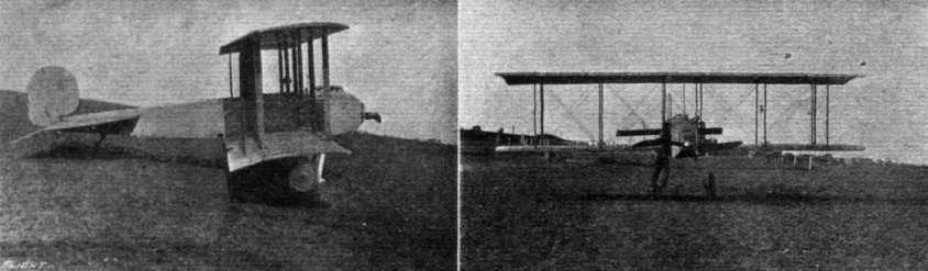
THE LATEST WRIGHT MILITARY SCOUT. - Views from the side and in front.
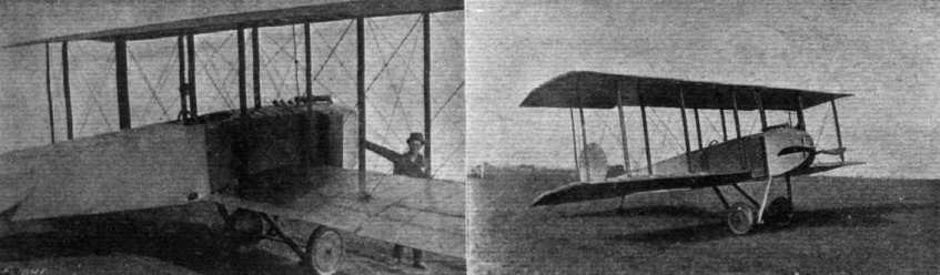
THE LATEST WRIGHT MILITARY SCOUT. - Three-quarter rear and front views respectively.
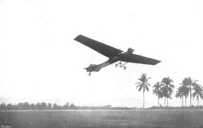
A Reminiscence. - An Antoinette monoplane flown by a Dutch pilot at Selangor, Federated Malay States, in 1911.
Different mountings and cowls of radial air-cooled engines.
AT HENDON. - In 19-- it may be that pilots will vol plane into Mitchell's tea gardens for the cup that cheers. The one shown was probably only on a reconnaissance trip. The Bleriot, in the shade of whose wings the tables are set, is that of the late G. Lee Temple.
Engines mounted between double bearers, and their housings.
Engines mounted between double bearers, and their housings.
Different mountings and cowls of radial air-cooled engines.

REMINISCENCES OF HENDON. - Rene Desoutter on a Caudron.

A group of some of Instructor C. M. Hill's pupils at the Hall Flying School, Hendon, in front of an all-British built Caudron, the engine being a 70 h.p. Isaacson, and the propeller an Ebora.
Different mountings and cowls of radial air-cooled engines.
Various engine mountings and housings.
Some engine mountings ad housings on "pusher" biplanes.

A French aeroplane on a bombing expedition "out yonder." A snap from another flight above the clouds.
Various engine mountings and housings.
Different mountings and cowls of radial air-cooled engines.
Various engine mountings and housings.
Different mountings and cowls of radial air-cooled engines.
Some engine mountings ad housings on "pusher" biplanes.
Flight, April 20, 1916.
A DUTCH CIRCUIT.
SOME time ago it was pointed out in these columns how many small neutral states are beginning to devote a considerable amount of money to the development of an air service. This is only natural in view of the immense importance aerial warfare has assumed, Besides, even the smallest of countries can afford to buy or build a number of aeroplanes even if they cannot afford an army or a navy. News has been received recently of a very good start made by Holland, in which country a fair number of machines are already in use. So far as it is possible to learn, the majority of these are of the H. Farman type and are built by the Spyker - or, to put the name in the Dutch spelling, Spijker - works, the aviation department director of which is the well-known Dutch aviator Henri Wijnmalen. A short time ago eight of these machines manned by pilot officers were flown in a circuit race starting from Soesterberg and going, via Gilze-Rijen-Scheveningen, back to Soesterberg again. One of the accompanying photographs shows the first pilot to arrive at Scheveningen, with his machine decorated with a wreath from the Spyker works. A visit was paid to the aerodrome by Her Majesty the Queen of Holland, who was greatly interested in the machines, several of the officers being presented to her.
Apart from "circuits," the Dutch military aviators are doing a good deal of cross-country flying en escadrille, and where, a few months ago, a single machine was seen, now several may often be seen in flight. One of our illustrations shows a view of Breda from above. This photo. was taken during an escadrille flight made by seven machines, under the leadership of van Heyst.

Her Majesty the Queen of Holland inspecting one of the Dutch military machines.
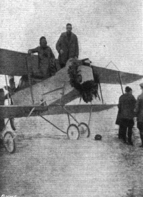
Lieuts. Palthe and Cramwinckel, who were the first to arrive at Schevenlngen in the Dutch Circuit In their machine, decorated with a wreath presented by the Spyker works.
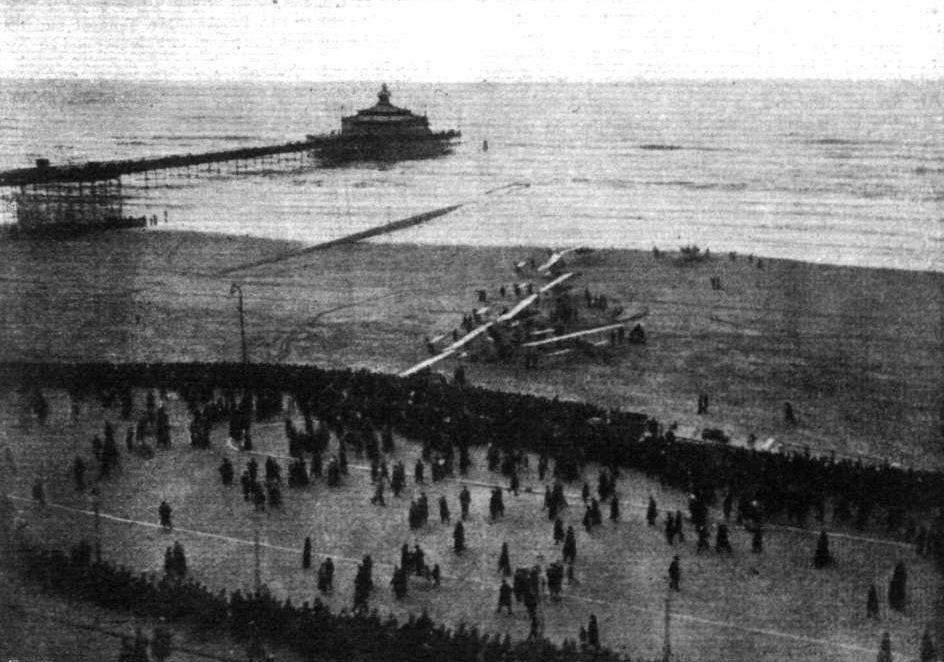
The machines lined up for the start of the Dutch Circuit.
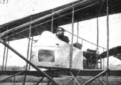
AVIATION IN JAPAN. - Japanese military aviator Lieut. Takeda, in the pilot's seat of the latest army biplane (M. Farman type) which he has been flying at Tokorozawa aerodrome.
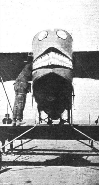
In the Mediterranean with the British Naval Forces. - A grotesque design decorating one of the aeroplanes of the R.N.A.S.
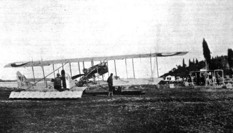
With the re-equipped Serbian Army at Corfu, showing the Serbian Aviation Park and preparing a machine for flight. It is due to the healthy climate of Corfu, the good food and rest in the island, that the Serbian Army has, after its terrible experiences, been brought back into such a splendid condition of health, and has been able to be re-equipped ready to take the field once again.
Mounting and housing of Vee-type air-cooled engines. Inset in centre, the Renault engine, showing tubular bearers.
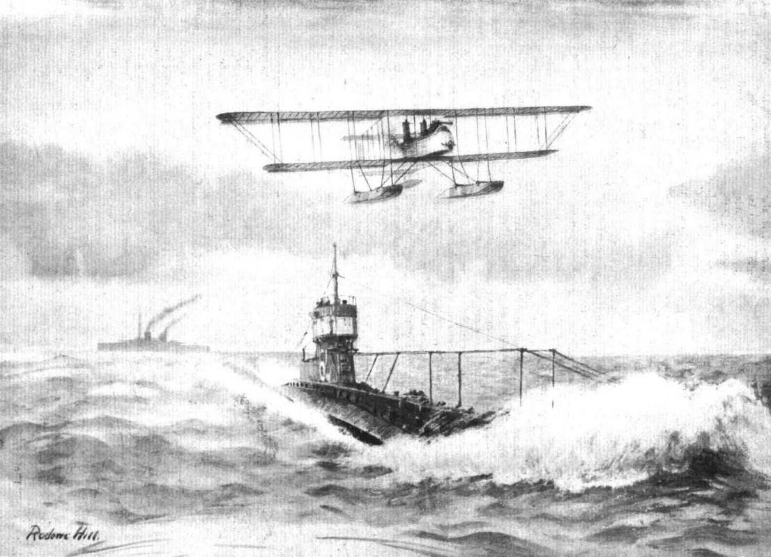
SEAPLANE AND SUBMARINE. - A study.
Engines mounted between double bearers, and their housings.
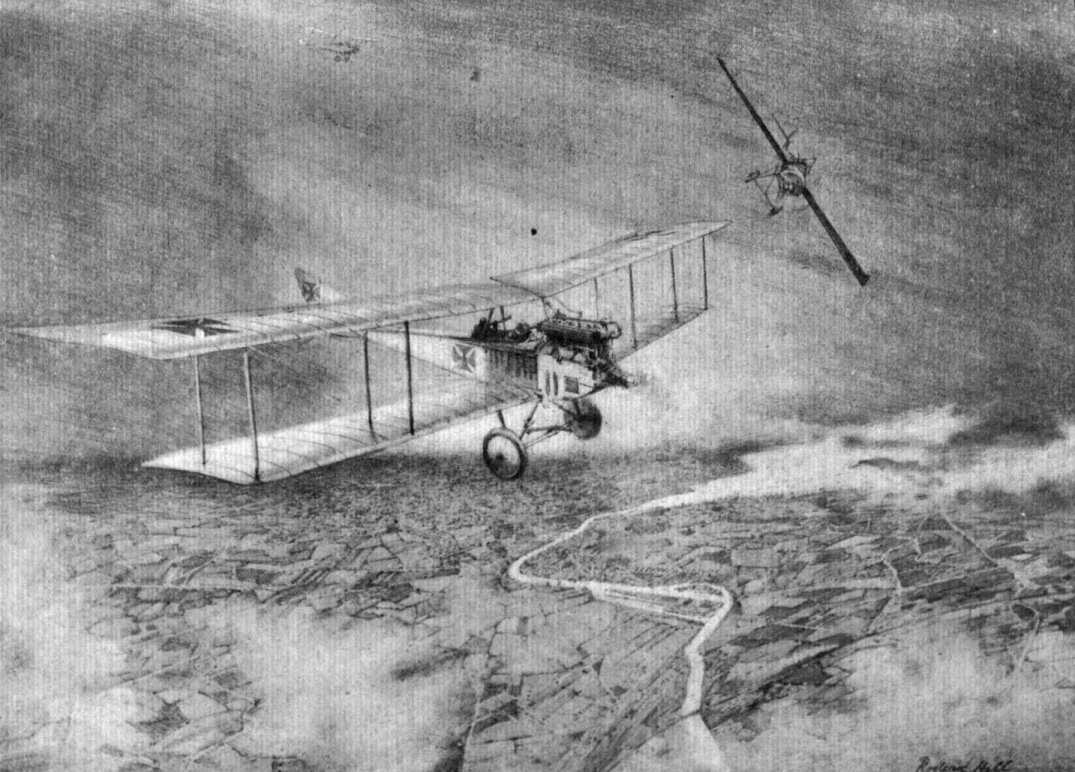
A French Morane monoplane engaging a German battleplane.
Various engine mountings and housings.

WAR IN THE AIR. - An attack upon a German A.E.G. biplane and an Aviatik. The latter subsequently hit and was brought down. This is but an example of many air fights of almost daily occurence at the Front, this particular incident being one of the "scraps" which Vedrines on his monoplane carried through, when fire machine-gun straight through the propeller field, the propeller being fitted with a deflector for warding off any stray bullets that may not get clear through between the revolving vanes. It is this principle which has been adopted in the Fokker.
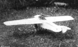
SCALE MODEL MADE BY MR. W. M. BUNCE FROM "FLIGHT" DRAWINGS - Nieuport.
Engines mounted between double bearers, and their housings.
Various engine mountings and housings.
Engines mounted between double bearers, and their housings.
Flight, October 19, 1916.
THE NIEUPORT BIPLANE-SCOUT.
"SOMEWHERE in France" there is a little band of Americans, known as the American Escadrille, who are doing good work at the Front in the French flying service. The Nieuport "one-and-a-half-plane" is used by these American pilots, and we are indebted to our contemporary, Aerial Age, for the following description of this machine, the first model of which was illustrated in "FLIGHT" for March 19th, 1915.
The top plane has a span of 24 ft. 6 ins. and a chord of 3 ft. 11 ins., whilst the lower plane is 23 ft. span and 2 ft. 4 ins. chord. The narrow lower plane allows a good range of vision, and the trailing edges of top and bottom planes being in line produces the effect of staggered planes. Both planes are slightly swept back, and thу lower one has a dihedral of about 8 ins. The upper plane, in two sections, is built up on two main spars 34 ins. apart. Above the pilot's seat the plane is cut away so that the pilot can easily reach the cockpit and also obtain a good view above to locate other aircraft or fire a machine gun. The ailerons, recessed in the upper plane only, are attached to tubes - indicated in the drawing by dotted lines - which run through the plane behind the rear spar to arms mounted above the fuselage. These arms are connected by rods passing inside the fuselage to a cross bar on the control column. This arrangement is shown in the accompanying diagram. The gap between the rear spar and the leading edge of the aileron is covered by an extension of the plane-covering. Each section of the lower plane is 10 ft. 5 ins. span, and has a single spar situated 9 ins. from the leading edge at the centre of pressure, the inner extremity forming the attachment to the fuselage. The attachment consists of a pivoted joint whereby the angle of incidence of the plane may be varied by rotating the spar by means of suitably arranged cranks and a hand lever.
Top and bottom planes are separated by one pair of struts on either side of the fuselage. Each pair, it will be seen, is in the form of a V, the struts converging at the bottom in a single strut-socket, which is so clamped around the spar that the latter may turn in it. The vertical member of the inclined V is 3 ft. 6 ins. in length, 4 ins. wide, with its upper end attached to the rear spar of the top plane. The inclined member is 3 1/2 ins. wide, and has its upper end attached to the front spar of the top plane. The struts are streamlined and bound at 1 ft. intervals with silk fabric. Struts supporting the top plane above the fuselage are oval-section steel tube.
The tail plane consist of a non-lifting stabilizing surface 1 ft. 5 ins chord by 7 ft. 9 ins. mean span, two elevator flaps of about 15 sq. ft. area, and a large vertical rudder. The stabilising plane is stayed by steel tubes from the bottom of the stern-post, and its trailing edge, to which the elevator are hinged, consists of a steel tube. The rudder is also a steel tube, and is hinged to the fuselage stern-post.
The usual girder box construction is employed for the fuselage, which has flat sides and bottom, a turtle-deck top following the curve of the engine cowel which is 40 ins diameter. Vertical members are light, T section, and the covering is fabric back of the pilot's cockpit and three-ply veneer forward. The seat is a few inches from the fuselage bottom and the wide cockpit allows for free movement of the arms. The fuselage is 33 ins, deep and 32 ins wide at the cockpit, tapering to 12 ins. deep at the stern post, whilst at the leading edge of the stabilising plane it is 8 ins. wide.
A V-type landing chassis is used, with a steel axle, sprung on rubber shock absorbers, carrying two 36 in disc wheels spaced 5 ft. 4 ins. apart. The streamline chassis struts are 4 ins. wide and 1 ins. thick, strongly braced with cable. The tail skid, which is of ash with a steel plate shoe is enclosed in a streamline shield of veneer. The control consists of a single vertical column in the centre of the cockpit operating the ailerons and the elevators by a side to side and forward-and-backward movement respectively, and a pivoted foot bar operating the rudder. The ailerons may also be operated by means of foot bat entirely separate from the rudder bar. All openings in the fuselage for control cables are reinforced with aluminium rings, 2 ins. diameter, riveted to the fabric. Where the elevator cables go through the tail plane there are slots, 6 ins. long, with aluminium edges. Small and easily removable doors are located at either side of the fuselage permitting inspection and adjustment of the control levers, &c.
An 80 h.p. Rhone engine is used, coupled direct to an 8 ft. Levasseur tractor screw The fuel tanks are situated at the rear of the engine in the top of the fuselage.
The following are the main characteristics, of this machine : Span, top plane. 24 ft. 6 ins.; bottom plane. 23 ft.; chord, top, 3 ft. 11 ins.; bottom, 2 ft. 4 ins.; supporting area, 145 sq. ft.; gap, 4 ft. 2 ins. (centre), 3 ft. 5 ins. (tips); length overall, 18 ft. 6 ins.
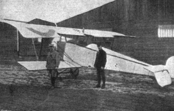
Three-quarter rear view of the Nieuport scouting biplane.

The American Escadrille and some of the Nieuport Scouts "somewhere" in France. - Reading from left to right are :- Lieut, de Laage, Sergt. C. C. Johnson (New York), Capt. Lawrence Rumsey (Buffalo), Sergt. J . R. McConnell (Carthage), Lieut. William Thaw (Pittsburgh). Sergt. R. Lufhery (New Haven, Conn.). Sergt. Kiffin Rockwell (Atlanta), Adjt. Didier Masson (Los Angeles), Sergt. Norman Prince (Boston), who has since died from wounds received last week, and Adjt. Bert Hall (Galveston).
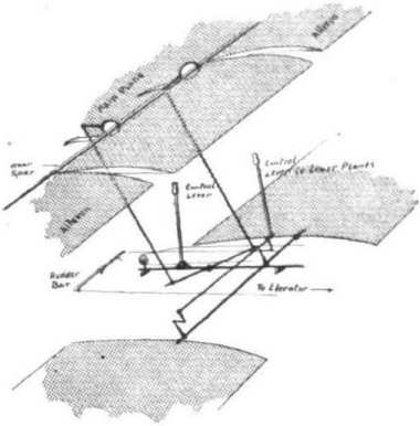
Diagram showing the controls for the ailerons and lower planes on the Nieuport scouting biplane.
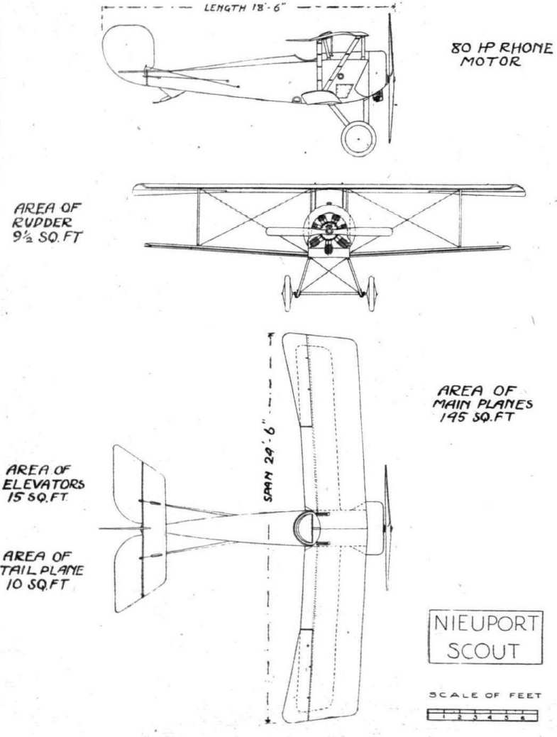
THE NIEUPORT SCOUTING BIPLANE. - Plan, side and front elevation to scale.
Engines mounted between double bearers, and their housings.

AVIATION IN JAPAN. - Three-quarter front view of the 70 h.p. army biplane No. 6 at Nagoya parade ground.