O.Thetford, P.Gray German Aircraft of the First World War (Putnam)
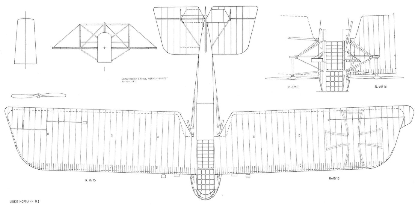
Linke-Hofmann R I
The design of the R I was taken up by the Breslau locomotive firm of Linke-Hofmann under the direction of Paul Stumpf, who became Chief Engineer when he joined them from the A.E.G. concern.
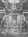
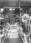
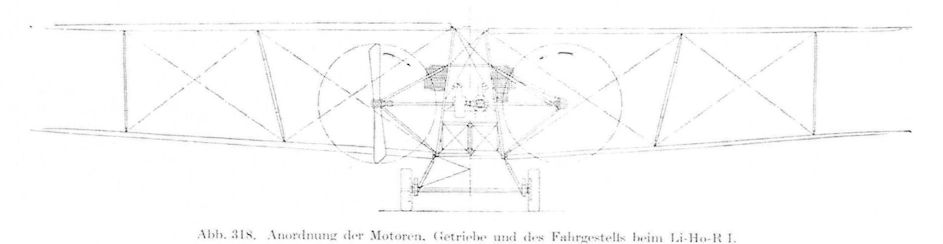
The fuselage design was developed as a result of model tests conducted in the Gottingen laboratory with encouraging results. Unfortunately the promise shown by the model was not realised in the actual aircraft when built. The four Mercedes D IVa engines were housed inside the fuselage and drove twin tractor airscrews through a system of shafts and gears.
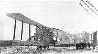
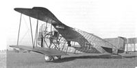
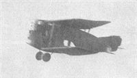
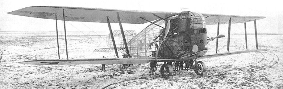
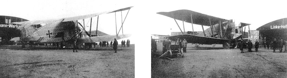
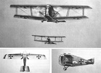
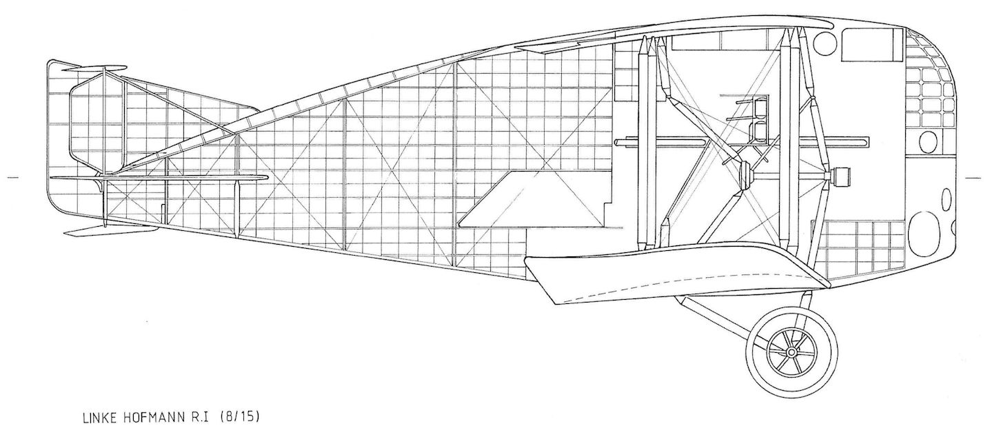
Of vast proportions and ungainly appearance the first R I (8/15) made its maiden flight in the spring of 1917, but proved difficult to fly. In May the machine crashed from a low altitude when the wings collapsed and was completely written off, all the crew but one fortunately escaping. One of the flight trials' difficulties was the development of an adequate landing technique as the pilots sat about 20 ft. above the ground and a considerably degree of judgement was necessary.
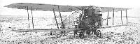
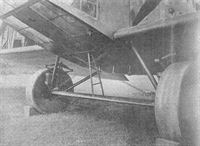
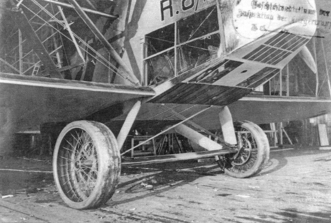
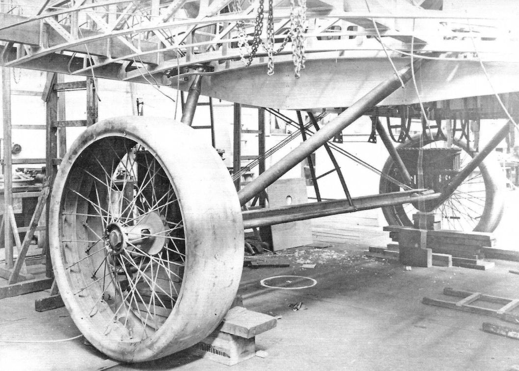
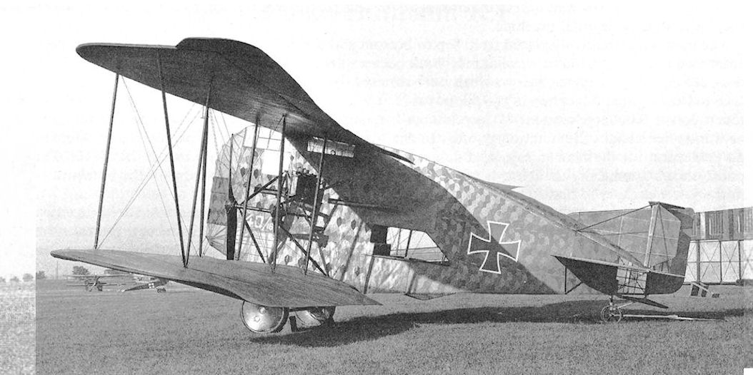
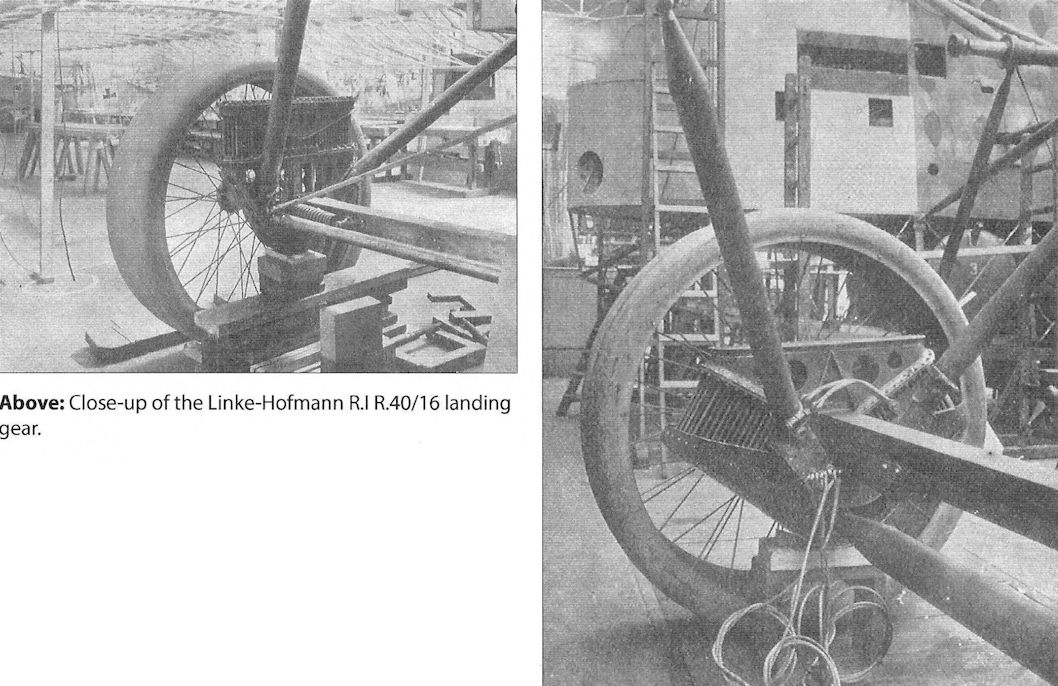
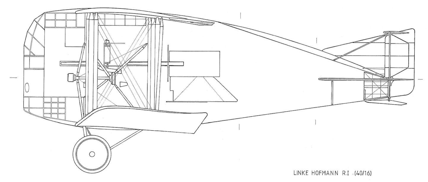
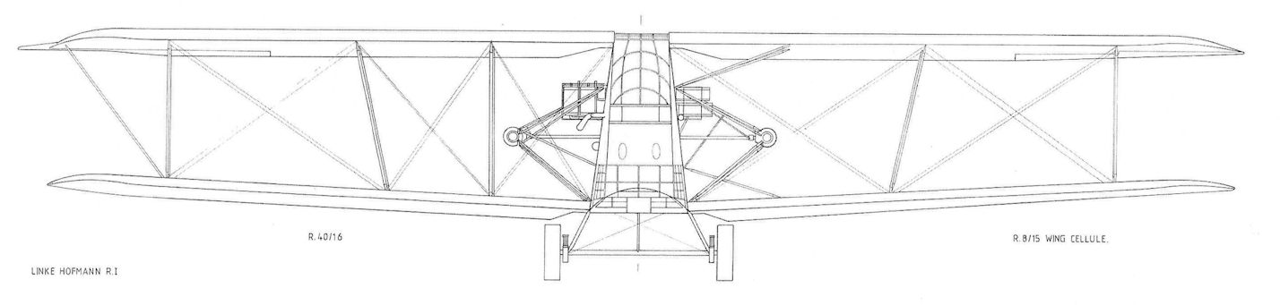
Towards the end of 1917, R I (40/16) was completed and included necessary modifications highlighted by R 8/15's shortcomings. Both machines were of wooden construction, the multiple tail surfaces being a distinctive feature, and a further unique point was the steel-tyred landing wheels incorporating a multiplicity of steel springs. The first prototype had the fuselage covered with transparent Cellon material, and the ailerons had inset balances. Performance of R 40/16 was still far from satisfactory, although manoeuvrability was improved. It eventually crash landed, nosed over, and was not rebuilt. Engines, 4 x 260 h.p. Mercedes D IVa. Span. 33.2 m. (108 ft. 11 1/4 in.). Length, 15.6 m. (51 ft. 2 1/2 in.). Height, 6.7 m. (21 ft. 11 3/4 in.). Area, 265 sq.m. (2,851 sq.ft.). Weights: Empty, 8,000 kg. (17,640 lb.). Loaded, 11,200 kg. (24,696 lb.). Speed, 130 km.hr. (81.25 m.p.h.). Climb, 3,000 m. (9,840 ft.) in 2 hr. Duration, 5 hr. Armament, none fitted.
Показать полностью
G.Haddow, P.Grosz The German Giants (Putnam)
Linke-Hofmann R.I
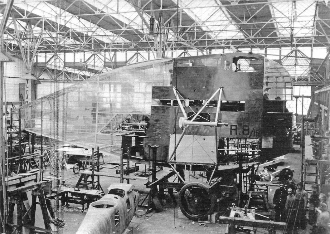
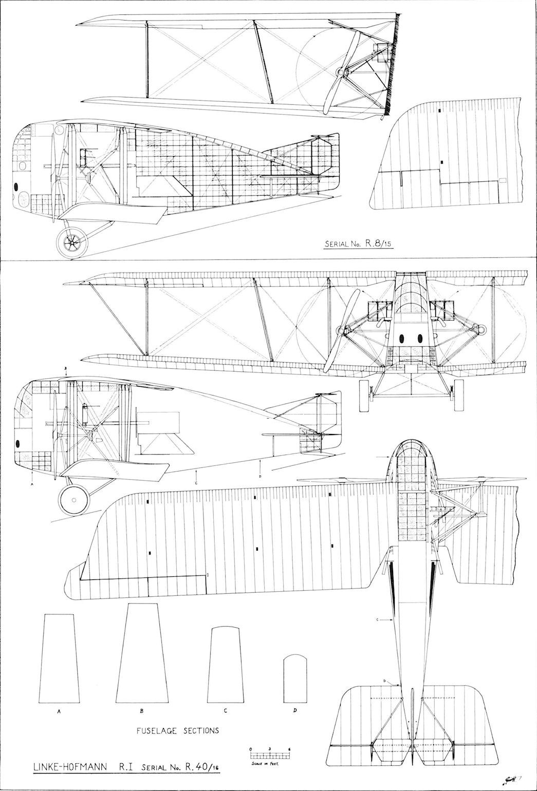
As military aviation grew in importance, many industrial concerns were drawn into the aircraft construction programme, even though some possessed no prior experience in this field. One such was the Linke-Hofmann Works of Breslau, manufacturers of locomotives and rolling stock. The company entered the aircraft field in 1916 by repairing and constructing under licence such aircraft as the Roland C.IIa, Albatros C.III, C.X and B.IIa. In the spring of 1916 Linke-Hofmann was awarded a contract to build a four engined R-plane despite the fact it had only been in the aircraft business for a relatively short time. Assembly of the R-plane, designated R.I 8/15, began in late 1916 and was completed in early 1917 under the leadership of chief engineer Paul Stumpf, formerly chief engineer of the AEG aircraft works, and Dr. Eichberg, the work manager. Professor Mann of Breslau performed the stress calculations. All R-plane test flights were performed at the Hundsfeld airfield near Breslau.
The chief characteristic of the R.I was its high, fat fuselage, an extremely awkward shape that looked aerodynamically unsound. But "form follows function". The relative inexperience of the engineering staff led it to seek assistance of the DVL laboratory at Gottingen. Here extensive wind-tunnel tests on models had shown that the "whale" fuselage which entirely filled the wing gap was endowed with a high lift-drag ratio. While this may have been true in the case of smaller machines (for example, the licence-built Roland C.IIa), it is doubtful whether the "whale" configuration was aerodynamically sound in larger aircraft for we do know that Li-Ho R.I's performance and flight characteristics left much to be desired.
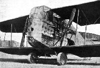
Evidently, Linke-Hofmann engineers had a free hand to try original and unusual ideas, for the R.8 had its rear fuselage completely covered with Cellon, a type of celluloid. This scheme, which had been tested on smaller aircraft, was an attempt at partial invisibility; however, it was soon found that the intense reflection from Cellon served to increase visibility rather than decrease it. Another disadvantage was that Cellon shrinks or stretches according to the weather, thereby creating constant changes of trim. It also rapidly turned yellow on exposure to sunlight. Linke-Hofmann was criticized for using Cellon, a new and untested material about which little was known, to cover the R.8, which itself was an experimental machine.
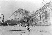
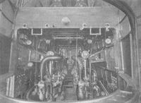
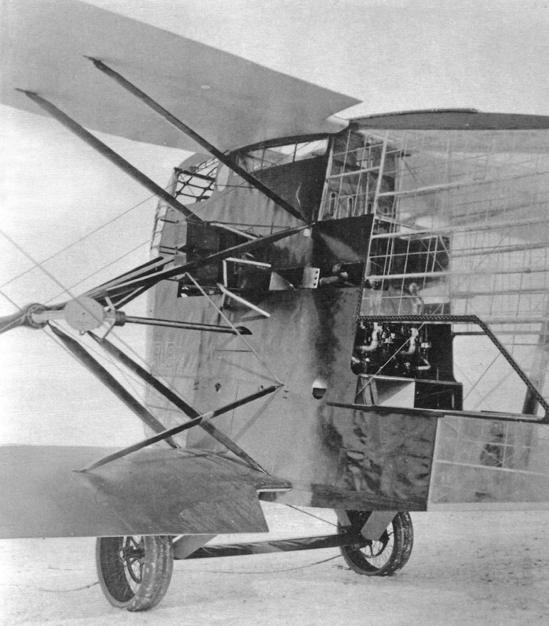
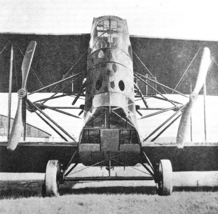
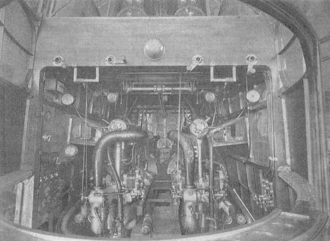
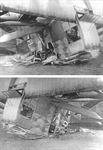
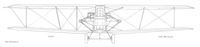
The nose was extensively glazed from top to bottom and divided into three levels. The upper deck contained the pilots' cabin (with what must have been a splendid view) and wireless station; the middle deck contained the engines, below which were situated the bomb-aimer's cabin and four fuel tanks. Due to the height and location of the pilots' cabin, it was extremely difficult for the pilots to judge the touch down. The large amount of "greenhouse" seriously decreased visibility in poor weather, rain or during searchlight illumination due to condensation and reflection. The exposed nose afforded no protection for the crew in case of a nose-over, as happened to the second model, the R.40. The photo shows graphically the hazards of the cabin, and one wonders what became of the bombardier in the lower deck, who had four engines and fuel tanks surrounding him.
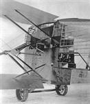
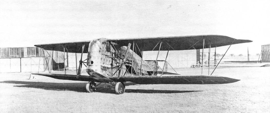
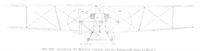
The R.I was powered by four 260 h.p. Mercedes D.IVa engines, a pair each mounted deep on either side of the fuselage parallel to the line of flight. Bevel gears connected each engine to a central drive shaft which ran across the fuselage between fore and aft engines and transmitted the power to an outrigger shaft and propeller gear-box.
One noteworthy feature of the R.I was that the propellers were mounted on an outrigger framework completely independent of wing structure. This innovation prevented vibrations, particularly those due to propeller or transmission failure, from affecting the wing structure directly.
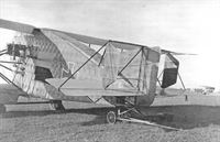
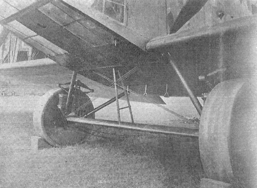
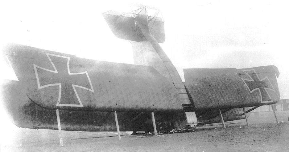
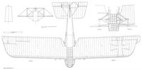
The wooden two-bay fabric-covered wings of the R.8 were extremely light, having in fact the lowest weight to total area ratio of any R-plane built. Ailerons were mounted on the upper wings only, and these were fitted with inset balancing surfaces. All four wingtips were "washed-out" at the trailing edges. The tail assembly included a curious pair of "flying" elevators mounted on top of the fin which operated in common with the conventional elevators mounted on the tailplane. The "flying" elevators were supported by the king posts of the two outboard rudders, and the whole assembly was braced by struts and cables. The undercarriage was a robust, simple V-type structure and carried a pair of massive steel-band wheels.
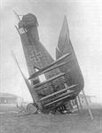
Testing of the R.8 began in January 1917, but flight were delayed because the unconventional steel tyres came apart during taxying trials. Improved tyres, fitted to the R.8 and subsequent Linke-Hofmann R-planes, worked quite well considering their unusual construction. In the spring of 1917 Hptm. Krupp piloted the R.8 on its maiden flight. During the course of the test programme, Krupp recalls that the flight characteristics of the R.8 began to suffer: the aircraft became mushy and almost uncontrollable, but the cause was not immediately determined. An outer diagonal strut was added at this time to stiffen the wings. On 10 May 1917 (6th test flight) Dr. Wittenstein and Lt. Hebart were at the controls when two wings collapsed at low altitude and the R.8 rammed into the ground with engines running at full power. All were saved with the exception of two mechanics who ran into the flames. In retrospect, it was determined that the exceedingly light wings warped and flexed in flight, with the resulting mushy feeling at the controls.
Because the R.8 was not fully tested at the time of its destruction, a series of improved models (R.I 40/16 to 42/16) were ordered by Idflieg. By the end of 1917 the R.40 was completed with certain modifications that incorporated the lessons learned from its predecessor. The wings, now greatly strengthened internally, were supported by three bays instead of two and fitted with overhanging balanced ailerons. The propeller gear-boxes were held by a new outrigger framework, more efficient radiators were mounted and the amount of Cellon was drastically reduced. The R.40 was equipped with the latest-type of landing gear designed by Linke-Hofmann engineers, who, incidentally, were particularly energetic and thorough in seeking solutions to the landing-gear problem. The shock absorbers consisted of many small steel coil springs arranged to take the place of rubber shock cords.
Dorsal, ventral and beam gun positions were provided, and the beam position allowed light to enter the engine compartment and permitted vapours to escape.
The performance attained by the R.40 was not satisfactory, but it was said that the aircraft had good manoeuvring qualities. The slow landing glide required a great deal of skill on the pilots' part, more so because of the high position of the cabin. During testing it is presumed that the pilot misjudged his height above ground. The R.40 landed hard and broke an axle, causing the aircraft to crash on its nose. It was probably not rebuilt after this accident. One pilot who today looks back on flying the R.I called it "not an aircraft but a sickness".
Modifications and Gottingen pedigree notwithstanding, the R.I design was unsuccessful, and acceptance was declined by Idflieg. A contemporary report states that the R.41 and R.42 were almost ready for acceptance in January 1918. Further information regarding the R.41 is lacking. The completed R.42 was photographed on the Linke-Hofmann aerodrome but details are not known.
Colour Scheme and Markings
R.8/15. The rear fuselage and tail were covered with transparent Cellon, allowing ribs and stringers to show through. The remainder of the fuselage and upper wing surfaces were painted in a dark colour, possibly olive-green or grey; the lower surfaces were painted a light colour. Plain black Patee crosses were painted over the Cellon on the fuselage. Those on the wings were edged in white. No markings were carried on the tail. The serial number was painted in black with white outlines on both sides of the nose.
R.40/l6. The machine was covered with printed camouflage fabric. The wing fabric was taped with light-coloured tape where it was sewn to the ribs; possibly it was light blue following the practice used on fighter aircraft. Patee crosses were painted on the wings and fuselage, but not on the tail. The serial number appeared in white on both sides of the nose.
SPECIFICATIONS
Type. Linke-Hofmann R.I 8/15 Linke-Hofmann R.140/16
Manufacturer: Linke-Hofmann Werke A.G., Breslau
Engines: Four 260 h.p. Mercedes D.IVa engines
Propeller Revolutions: 750 r.p.m.
Dimensions.
Span, 32•02 m. (105 ft. 0 1/2 in.) 33•2 m. (108 ft. 11 in.)
Chord upper, - 5 m. (16 ft. 5 in.)
Chord lower, - 4•7 m. (15 ft. 5 in.)
Length, 15•56 m. (51 ft. 0 1/2 in.) 15•6 m. (51 ft. 2 in.)
Height, 6•78 m. (22 ft. 3 in.) 6•7 m. (22 ft.)
Propeller diameter, - 4•3 m. (14 ft. 1 in.)
Areas:
Wings, 264 sq. m. (2841 sq. ft.) 265 sq. m. (2851 sq. ft.)
Weights:
Empty, 5800 kg. (12,789 lb.) 8000 kg. (17,640 lb.)
Loaded, 9000 kg. (19,845 lb.) 11,200 kg. (24,696 lb.)
Useful load, - 3200 kg. (7056 lb.)
Wing Loading: 42•3 kg./sq. m. (8,7 lb./sq. ft.)
Performance:
Maximum speed, 140 km.h. (87 m.p.h.) 130 km.h. (80'8 m.p.h.)
Climb with full load, - 3000 m. (9843 ft.) in 120 mins.
Armament: Provision for dorsal, ventral and beam machine-gun positions
Service Use: None
Показать полностью
Jane's All The World Aircraft 1919
Little is known of this firm, which was not much heard of till the Armistice, when certain illustrations of its products appeared in the German Press.
It is stated that none of its products have been used in any war area.
Показать полностью
J.Herris German Aircraft of Minor Manufacturers in WW1. Vol II (A Centennial Perspective on Great War Airplanes 50)
Linke-Hofmann
The firm of Linke-Hofmann dealt with mechanical design and manufacturing, mostly locomotives and railway equipment in peace time, and in 1916 created a joint stock company, Linke-Hofmann Werke AG Abteillung Flugzeugbau, in the same premises. The firm commenced by repairing aircraft but by the end of the year they had acquired a licence to produce their own aircraft. It undertook to study giant planes (R-types) that used centralized engines, that is to say, united in the central fuselage.
During 1916 the firm repaired 80 machines and built 15 new aircraft. In 1917 the figures were 112 and 80; 1918 they were 80 and 20 respectively. This does not include R-types.
The following types were produced:
LFG Roland C.IIa (1 prototype + 52 production); Albatros C.Id and C.If (100 ordered but doubtful any were completed); Albatros C.III 75; Albatros C.X 50; Albatros B.IIa (about 150); and three R types - R.I 8/15 and 40/16 and R.II 55/17. The R.III was under construction but never finalised before the Armistice.
The firm commenced work with about 450 workmen and 18 staff. In 1917 the numbers had risen to 430 and 47 respectively, but in 1918 the workforce for the production of the R-types had been reduced to 130 men. Despite much experimental work done by the firm, tangible results were not achieved.
Linke-Hofmann R.I
Having been asked to design and build giant aircraft, Linke-Hofmann's first design was the distinctive R.I. The aircraft had a short, fat fuselage that completely filled the gap between its biplane wings, a configuration that research had shown had a high lift-drag ratio. This 'whale' design was used for low drag but the resulting performance and flight characteristics were mediocre despite its streamlining.
Given the military designation R.I 8/15, the R.I was powered by four reliable 260 hp Mercedes D.IVa engines that were installed in the fuselage. These were connected together in two pairs, one pair on each side of the fuselage mounted to connect to a drive shaft via a bevel gear. Each drive shaft drove a pair of propellers between the wings, one mounted forward as a tractor and the other aft as a pusher. Each drive shaft drove propellers on one side of the aircraft. The purpose of this complex arrangement was to enable all propellers to remain powered even in case of an engine failure. In this time of fixed pitch propellers, they could not be feathered to minimize drag if an engine failed. A windmilling propeller creates drag similar to an open parachute of the same diameter, and this drag meant a two-engine aircraft could not maintain altitude with an engine failure.
The nose of the R.I was extensively glazed and was deep enough to be divided into three levels. The pilots' cockpit was on the upper level with the radio operator's position behind them. The middle deck contained the engines and the lower deck housed the bombardier's cockpit and the four fuel tanks.
The rear of the fuselage was covered with Cellon. The purpose was to give partial invisibility of the airplane, a technology that was also tested on smaller aircraft and the final rebuild of the Staaken VGO.I. However, Cellon was shiny and reflected the light more than fabric, so increased the aircraft's visibility instead of reduced it. Cellon also expanded and shrank with temperature and humidity and turned yellow after prolonged exposure to sunlight. These problems eliminated further interest in Cellon covering, but R.8 used it.
R.8 had two-bay wings of light structure with ailerons mounted on the upper wings only. The ailerons had inset aerodynamic balances. When the R.8 was destroyed during flight testing, Idflieg ordered an improved series, R.I 40-42/16. The wings of R.40 were greatly strengthened with 3-bay wing bracing and the ailerons had external horn aerodynamic balances.
The R.8 was built in 1916 and testing started in January 1917. It initially used steel wheels but these failed during taxi tests and were replaced by improved tires. The maiden flight of R.8 was in the spring of 1917. On May 10, 1917 R.8 crashed after two wings collapsed when flying at low altitude at full power. The crew survived except for a mechanic who ran into the flames. The root cause of the accident was weak wing structure. The weak wings had also caused problems in flight due to wing flexing.
R.I R.40-42/17 were ordered after the crash of R.8 with greatly strengthened wings. Other modifications compared to R.8 included new structure to hold the propellers, more efficient radiators, improved landing gear, provision for dorsal, ventral, and beam machine-gun positions, and a great reduction in the amount of Cellon covering. R.40 had good maneuvering and flying qualities although the performance was still unsatisfactory. The next two aircraft of the batch, 41/17 and 42/17, were almost ready for acceptance in January 1918 but as far as is known these were not completed and Idflieg abandoned further interest in the type.
Schutte-Lanz R.I 8/15 Specifications
Engine: 4 x 260 hp Mercedes D.IVa
Wing: Span 32.02 m
Wing Area 264 m2
General: Length 15.56 m
Height 6.78 m
Empty Weight 5800 kg
Loaded Weight 9000 kg
Maximum Speed: 140 km/h
Schutte-Lanz R.I 40/16 Specifications
Engine: 4 x 260 hp Mercedes D.IVa
Wing: Span 32.2 m
Chord, upper 5 m
Chord, lower 4.7 m
Wing Area 265 m2
General: Length 15.6 m
Height 6.7 m
Empty Weight 8000 kg
Loaded Weight 11,200 kg
Maximum Speed: 130 km/h
Climb: 3000 m 120 min.
Показать полностью
M.Dusing German Aviation Industry in WWI. Volume 1 (A Centennial Perspective on Great War Airplanes 84)
Linke-Hofmann Werke AG, Breslau (now Wroclaw), (Li)
Foundation:
The original company was founded in 1841 in Breslau by Gottfried Linke and became a joint stock company in 1871. Aircraft construction itself was not started until after the outbreak of World War 1 in 1916.
Aircraft Development:
In 1916, Linke-Hofmann Werke were particularly involved in aircraft repairs. At the end of 1916, the company began building new aircraft under license. At the same time, Linke-Hofmann also developed its own designs, especially R-airplanes.The only type built and accepted was an R airplane designated Li R I.
<...>
Показать полностью
Журнал Flight
Flight, October 2, 1919.
THE LINKE-HOFMANN GIANT MACHINES
OF the firms that have designed and constructed large, multi-engined aeroplanes during the War, special interest attaches to those created by the Linke-Hofmann Works, Breslau, not only on account of their size, but also because their designer has evidently attempted to get away from the stereotyped design in which a multiplicity of engines are simply dumped on the wings and made to drive, direct, tractor or pusher airscrews. That placing the engines on the wings in this manner is a short cut to high-power propulsion is admitted, but it does not by any means follow that this is the type of multi-engined machine that will survive. It is therefore of interest to examine what others have done in their attempts to effect improvements. In our issue of last week we published particulars of some German D.F.W. multi-engined machines in which the engines were placed in the fuselage and which had shaft and bevel drives to airscrews placed on the wings. The following notes, which are translated from a descriptive article in Flugsport, deal with a similar subject, and show how another firm has tackled the problem in a somewhat different way.
"The Linke-Hofmann Works, of Breslau, took up the design and construction of Giant aeroplanes (Riesenflugzeuge) under the direction of their chief engineer Paul Stumpf, who was formerly chief engineer to the Allgemeine Elektricitats Gesellschaft (A.E.G.). Two types were built, the R I and the R II, both of which had the engines placed in the fuselage.
The Linke-Hofmann. Type R I.
"This machine, which is shown in the accompanying photographs, had two tractor airscrews driven by four Mercedes engines of 260 h.p. each, giving a total of 1,040 h.p. The dimensions and weights of the machine were as follows :- Span, 109 ft. 6 in., length o.a. 51ft. 6 in.; chord, upper plane, 16 ft. 6 in.; chord, lower plane, 15 ft. 6 in.; height, 22 ft.; wing area, 2,850 sq. ft.; weight empty, 17,600 lb.; useful load, 7,000 lb., including fuel for 5 hours' flight. The machine attained a speed of 80 m.p.h. and with a useful load of 7,000 lb. climbed to 9,900 ft. in 2 hours. The slow glide in which the machine landed was very peculiar. As the pilot's seat was placed very high, it required a good deal of practice to learn to land the machine successfully. The rudder and elevator control was satisfactory, but the machine was somewhat sluggish on the ailerons. When taxying on the ground she answered the rudder very well.
"The effort required on the part of the pilot for rudder, elevator, and aileron control was little greater than in the case of a small machine, and the R 1 was flown often by only one pilot. The very deep fuselage did not appear to have any adverse effect on either the flying or the steering of the machine, On the contrary, the machine was found to have much of the stability of the old Tauben. This was thoroughly tested during an hour's flight in a wind of 50 ft. per second.
"As a result of model tests at the Gottingen laboratory, the fuselage was carried right up to the top plane. The increased lift resistance ratio of the complete machine which the model tests appeared to promise as a result of this deep body did not, unfortunately, materialise in the actual machine.
"The ventilation of the engine room was very good, and on account of the accessibility of the engines during flight, minor defects could easily be remedied. The undercarriage was of the same simple Vee type as that of smaller machines, and was found to be very light and at the same time strong. During a series of test nights, including a number of heavy landings, any minor defects in it were discovered and put right. The wheels were of iron, and were fitted with solid tyres.
Показать полностью