
Книги
Centennial Perspective
J.Herris
German Aircraft of Minor Manufacturers in WW1. Volume II
254
J.Herris - German Aircraft of Minor Manufacturers in WW1. Volume II /Centennial Perspective/ (50)
Unknown trainer with 4-cylinder engine, bulbous nose, and tricycle landing gear. Was this an early AEG trainer?
The modest Markische company facilities. Halberstadt fighters are at left and an Albatros C.III is at right. (Peter M. Grosz collection, STDB)
Schwade built some Aviatik P.20 biplanes. (Peter M. Grosz collection, STDB)
The modest Markische company facilities. Halberstadt fighters are at left and an Albatros C.III is at right. (Peter M. Grosz collection, STDB)
Karl Krieger
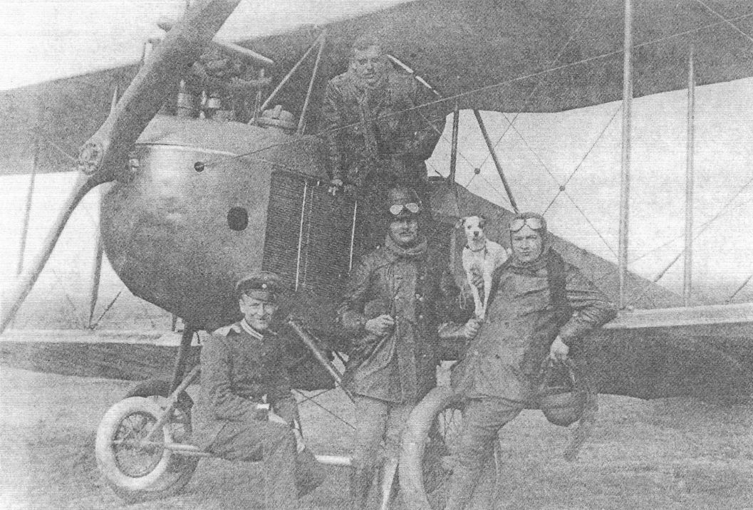
Karl Krieger, born on 26 December 1885 in Crefeld, was the Emperor's chauffeur. He had first exhibited a model aircraft at the ILA in Frankfurt in 1909. Krieger used the pseudonym "Krieger" for this, as his official position did not allow him to be active part-time.
Shortly afterwards he was on his own request released from his duties as chauffeur so that he could devote himself entirely to aircraft construction. When the Johannisthal airfield was built, Krieger first moved to the "old take-off site", set up a workshop, and in 1910 built a monoplane, with which he only achieved short flights. His main income, however, came from flying aircraft of other companies.
One year later, namely on September 12, 1911, Krieger took of with his own new, improved monoplane and fulfilled the conditions for the acquisition of the pilot license (# 113). In 1912 he built a Taube monoplane and in 1913 another monoplane with a 100 hp Benz engine.
In the following month he trained student pilots and took part in almost all national flying competitions.
<...>

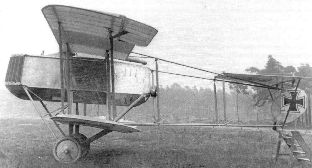
The Krieger Taube at Johannisthal. Power was a 100-150 hp 6-cylinder engine, likely a Benz from the image. Streamlined for the time, it featured ailerons for roll control. A brow radiator was fitted. (Peter M. Grosz collection, STDB)
The Krieger Taube at Johannisthal. Power was a 100-150 hp 6-cylinder engine cooled by a brow radiator. It featured ailerons for roll control and was streamlined for its time. (Peter M. Grosz collection, STDB)
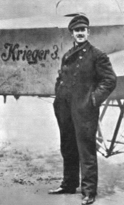
Karl Krieger standing next to Krieger #3.
Karl Krieger
<...>
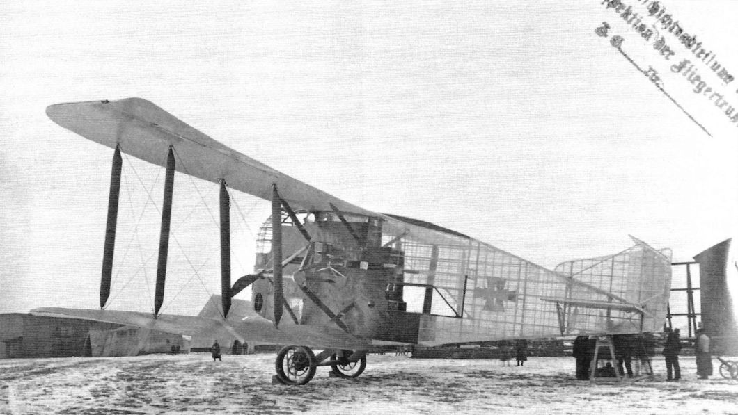
Together with his brother Oskar, he built a torpedo aircraft in 1914, which he wanted to patent. Alarmed by this writing, the Reichsmarineamt confiscated the triplane, but Krieger took legal action against it and won. The Reichsmarineamt then had to pay 50,000 Marks in damages, which, however, failed to materialise due to the war that had broken out in the meantime.
<...>
<...>
Together with his brother Oskar, he built a torpedo aircraft in 1914, which he wanted to patent. Alarmed by this writing, the Reichsmarineamt confiscated the triplane, but Krieger took legal action against it and won. The Reichsmarineamt then had to pay 50,000 Marks in damages, which, however, failed to materialise due to the war that had broken out in the meantime.
<...>
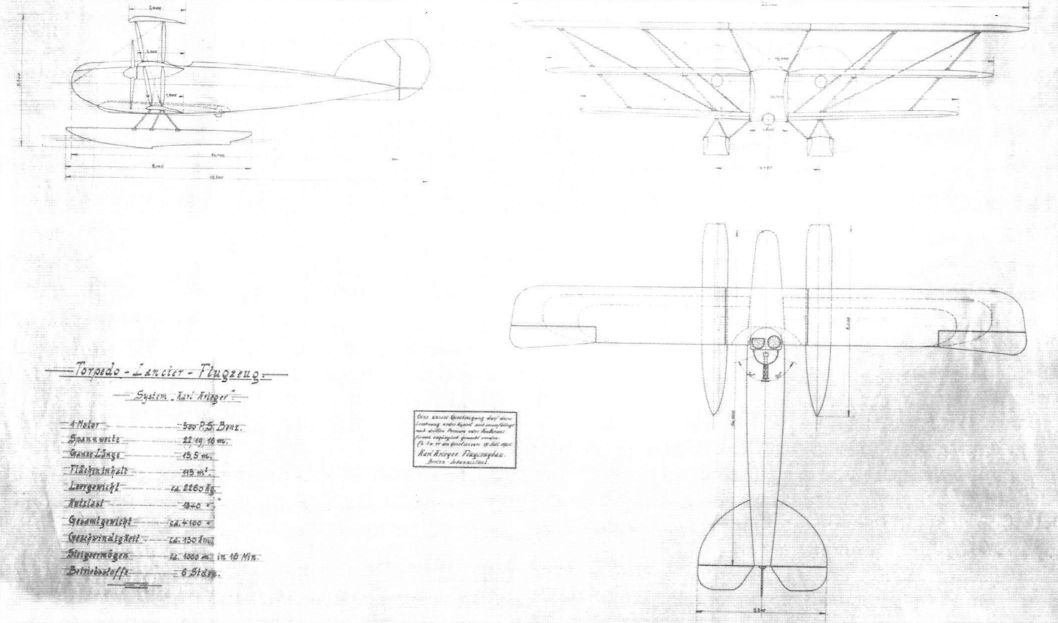
The Krieger torpedo bomber project remained un-built. (Peter M. Grosz collection, STDB)
Karl Krieger
<...>
In 1914, Karl Krieger presented a so-called parasol-monoplane, as the high wing aeroplanes were called.
<...>
In 1915/1916 the company in Johannisthal was closed down. Krieger had meanwhile moved to Leipzig and was employed by the Germania-Flugzeugwerke as a company pilot/test pilot. He was killed in a crash on August 8, 1918, when a Rumpler he was testing crashed.
Krieger
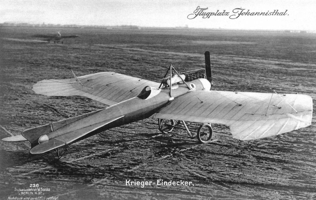
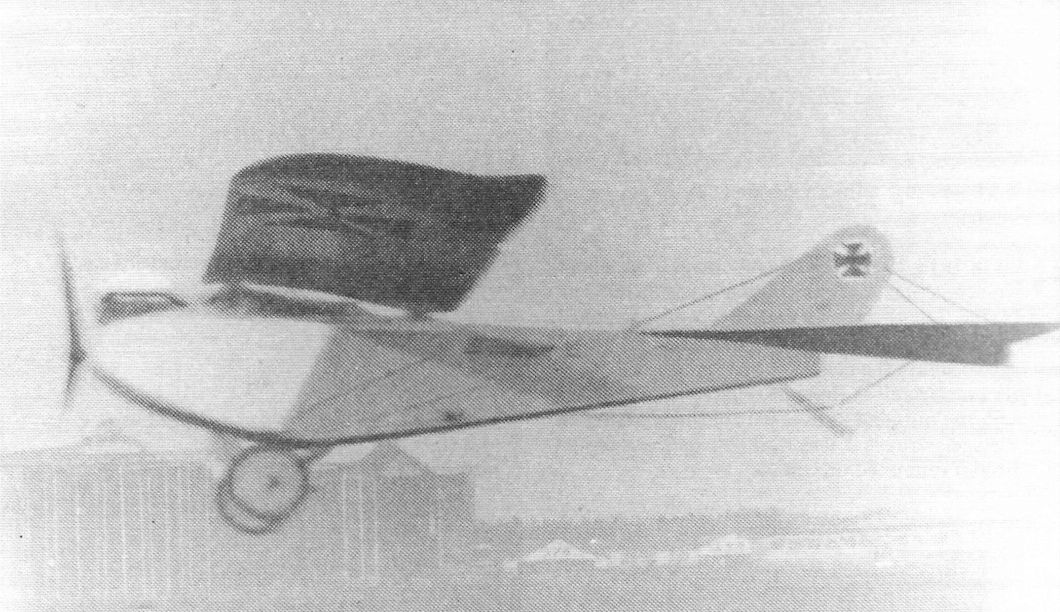
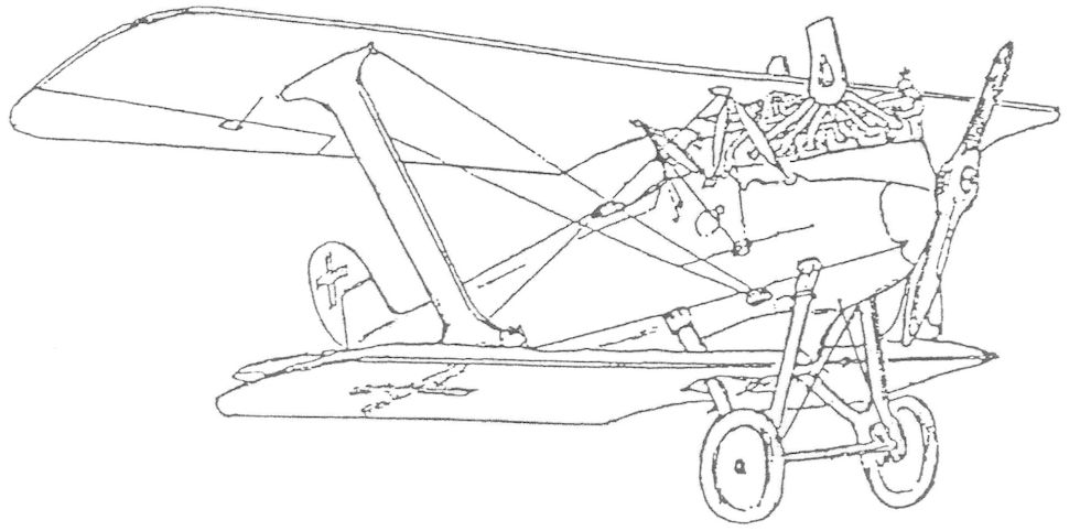
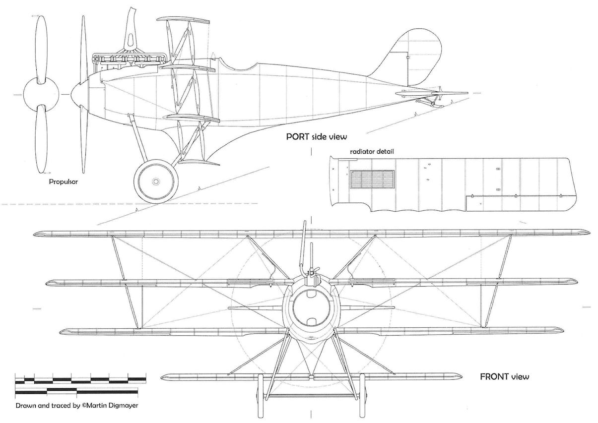
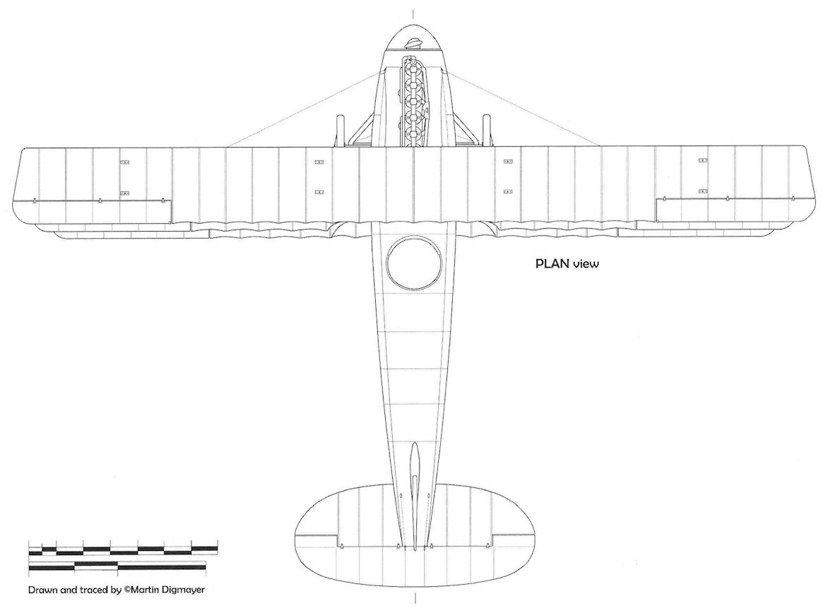
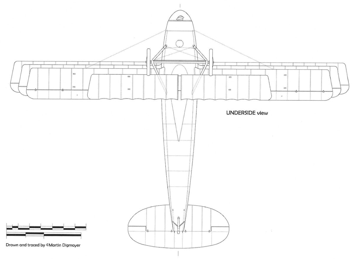
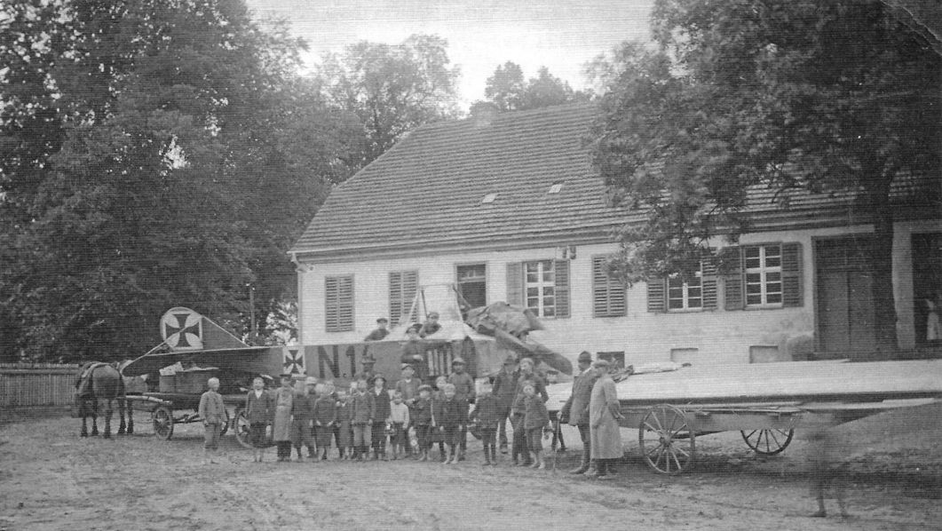
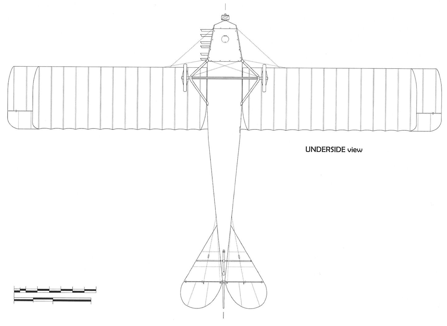
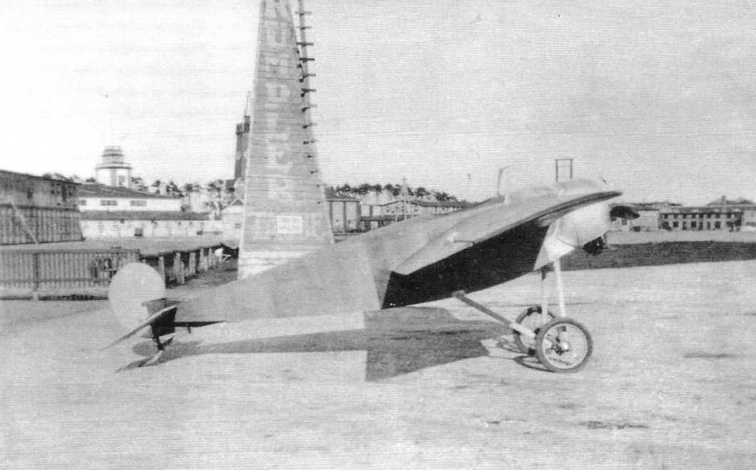
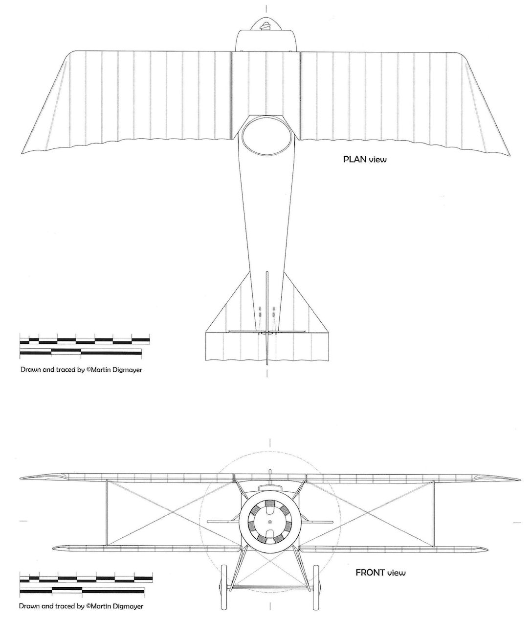
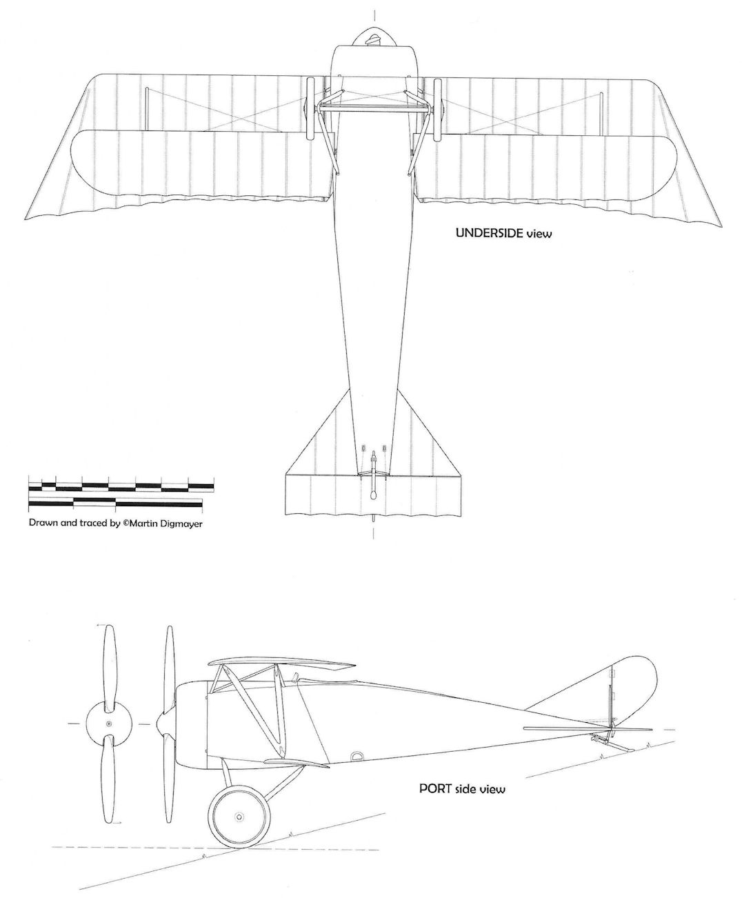
Built in 1915, the Karl Krieger parasol monoplane two-seater was made of tubular steel. Span was 14.3 m, length about 9 m, and wing area about 30 m2. The wings could be moved fore and aft on the fuselage to adjust the center of gravity as needed.
Only one aircraft is thought to have been built; although the numeral '5' was part of the lettering on the fuselage; perhaps it was Karl Krieger's 5th design. The aircraft remained unarmed.
<...>
In 1914, Karl Krieger presented a so-called parasol-monoplane, as the high wing aeroplanes were called.
<...>
In 1915/1916 the company in Johannisthal was closed down. Krieger had meanwhile moved to Leipzig and was employed by the Germania-Flugzeugwerke as a company pilot/test pilot. He was killed in a crash on August 8, 1918, when a Rumpler he was testing crashed.
Krieger
Built in 1915, the Karl Krieger parasol monoplane two-seater was made of tubular steel. Span was 14.3 m, length about 9 m, and wing area about 30 m2. The wings could be moved fore and aft on the fuselage to adjust the center of gravity as needed.
Only one aircraft is thought to have been built; although the numeral '5' was part of the lettering on the fuselage; perhaps it was Karl Krieger's 5th design. The aircraft remained unarmed.
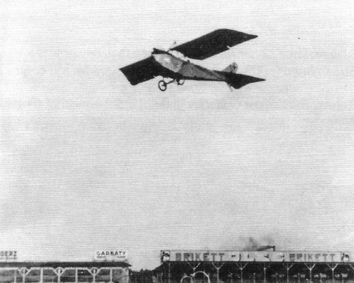
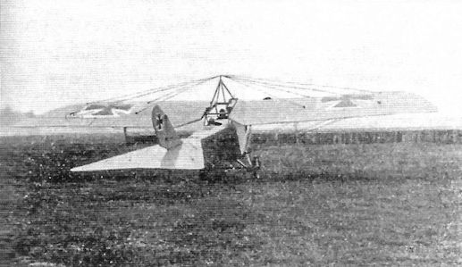
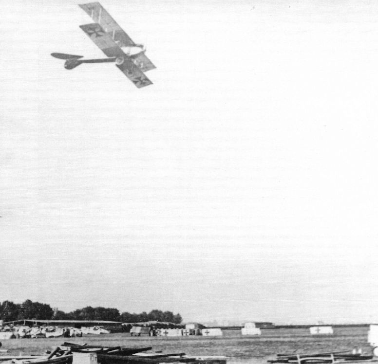
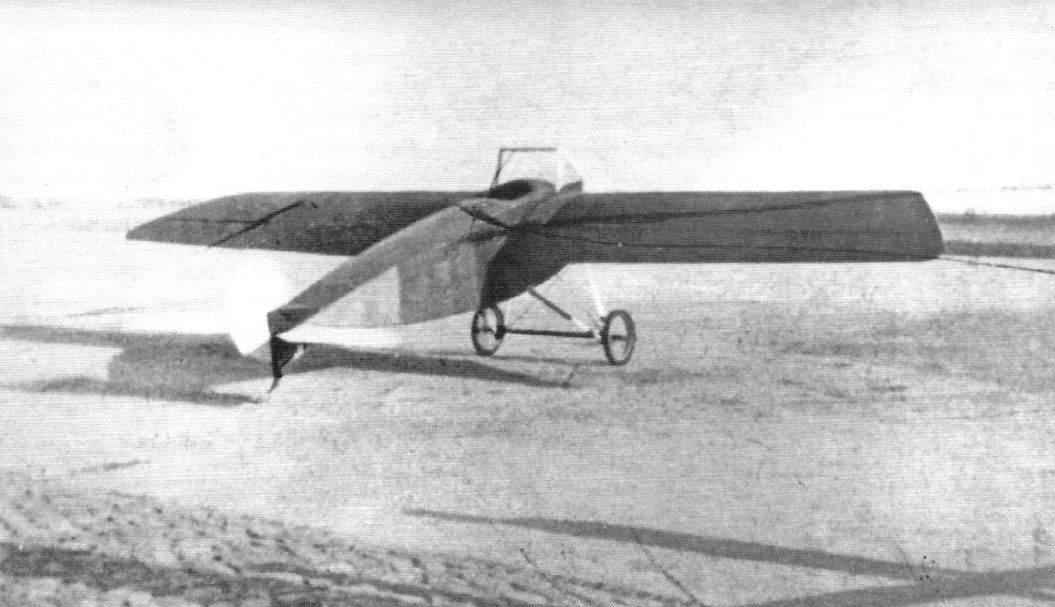
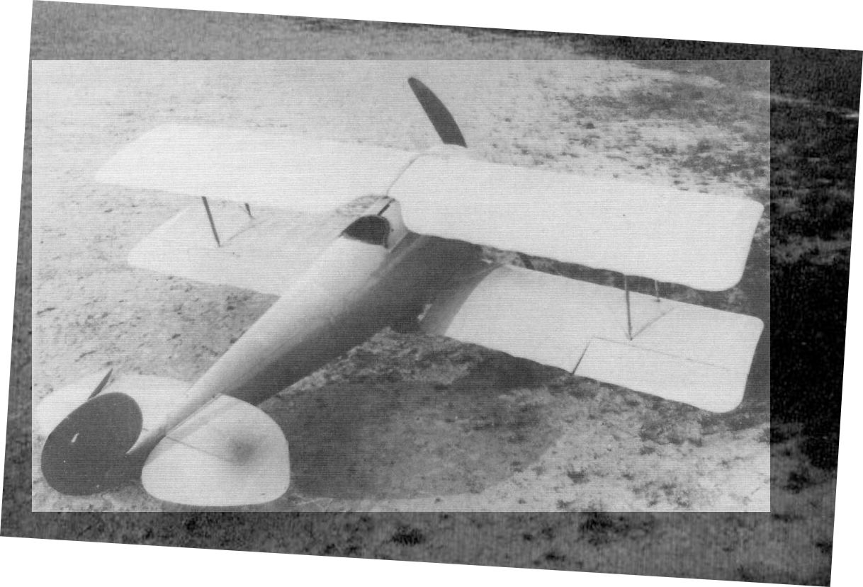
The Krieger Eindecker in flight at Johannisthal. (Peter M. Grosz collection, STDB)
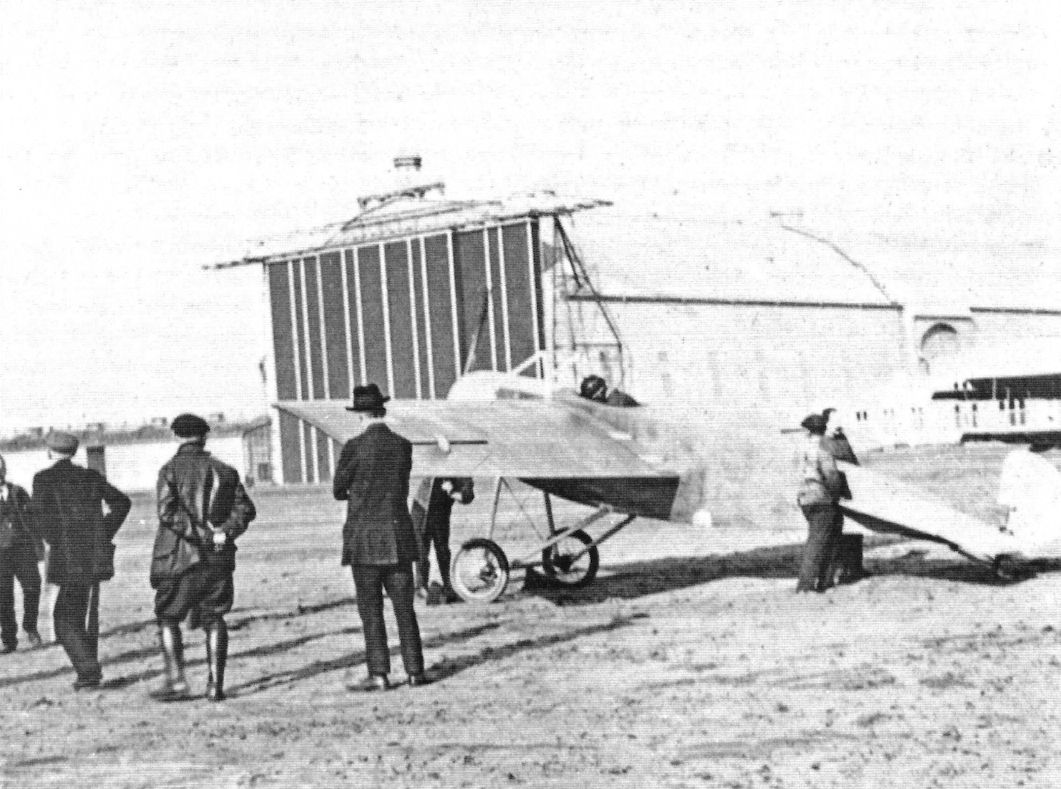
The Krieger Eindecker at Johannisthal. (Peter M. Grosz collection, STDB)
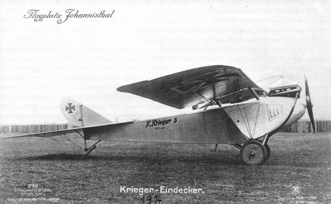
The Krieger Eindecker at Johannisthal. Power was a 100-150 hp 6-cylinder engine, likely a Benz from the image. The number '5' may indicate Krieger's 5th design. (Peter M. Grosz collection, STDB)
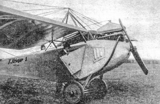
The Krieger Eindecker at Johannisthal.
Linke-Hofmann
The firm of Linke-Hofmann dealt with mechanical design and manufacturing, mostly locomotives and railway equipment in peace time, and in 1916 created a joint stock company, Linke-Hofmann Werke AG Abteillung Flugzeugbau, in the same premises. The firm commenced by repairing aircraft but by the end of the year they had acquired a licence to produce their own aircraft. It undertook to study giant planes (R-types) that used centralized engines, that is to say, united in the central fuselage.
During 1916 the firm repaired 80 machines and built 15 new aircraft. In 1917 the figures were 112 and 80; 1918 they were 80 and 20 respectively. This does not include R-types.
The following types were produced:
LFG Roland C.IIa (1 prototype + 52 production); Albatros C.Id and C.If (100 ordered but doubtful any were completed); Albatros C.III 75; Albatros C.X 50; Albatros B.IIa (about 150); and three R types - R.I 8/15 and 40/16 and R.II 55/17. The R.III was under construction but never finalised before the Armistice.
The firm commenced work with about 450 workmen and 18 staff. In 1917 the numbers had risen to 430 and 47 respectively, but in 1918 the workforce for the production of the R-types had been reduced to 130 men. Despite much experimental work done by the firm, tangible results were not achieved.
Linke-Hofmann R.I
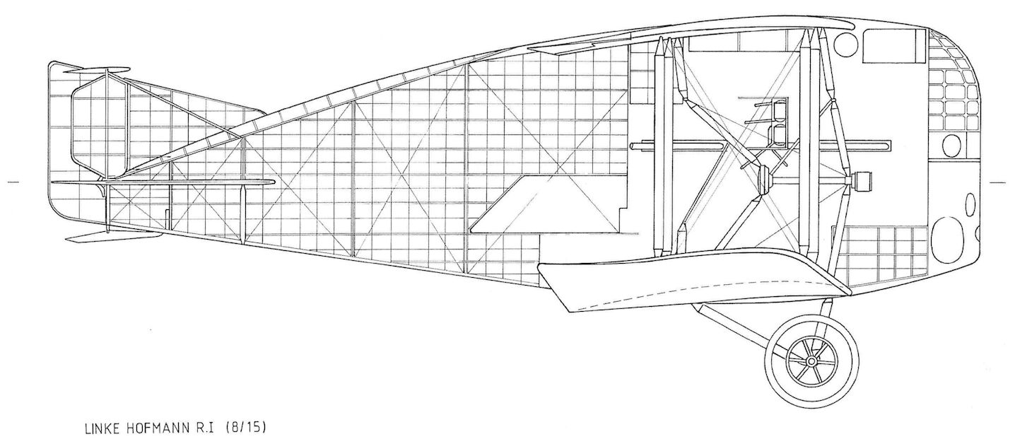
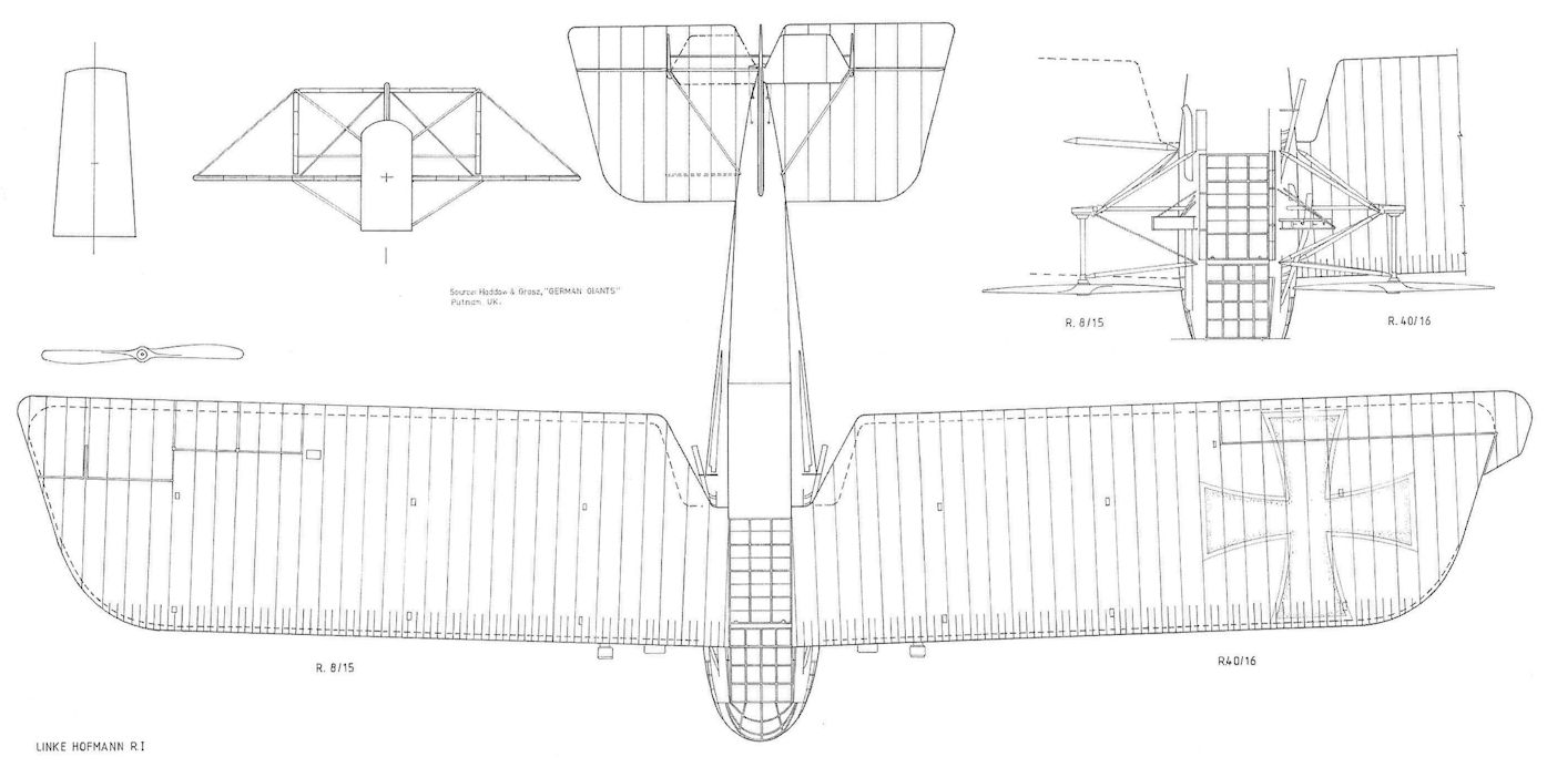
Having been asked to design and build giant aircraft, Linke-Hofmann's first design was the distinctive R.I. The aircraft had a short, fat fuselage that completely filled the gap between its biplane wings, a configuration that research had shown had a high lift-drag ratio. This 'whale' design was used for low drag but the resulting performance and flight characteristics were mediocre despite its streamlining.
Given the military designation R.I 8/15, the R.I was powered by four reliable 260 hp Mercedes D.IVa engines that were installed in the fuselage. These were connected together in two pairs, one pair on each side of the fuselage mounted to connect to a drive shaft via a bevel gear. Each drive shaft drove a pair of propellers between the wings, one mounted forward as a tractor and the other aft as a pusher. Each drive shaft drove propellers on one side of the aircraft. The purpose of this complex arrangement was to enable all propellers to remain powered even in case of an engine failure. In this time of fixed pitch propellers, they could not be feathered to minimize drag if an engine failed. A windmilling propeller creates drag similar to an open parachute of the same diameter, and this drag meant a two-engine aircraft could not maintain altitude with an engine failure.
The nose of the R.I was extensively glazed and was deep enough to be divided into three levels. The pilots' cockpit was on the upper level with the radio operator's position behind them. The middle deck contained the engines and the lower deck housed the bombardier's cockpit and the four fuel tanks.
The rear of the fuselage was covered with Cellon. The purpose was to give partial invisibility of the airplane, a technology that was also tested on smaller aircraft and the final rebuild of the Staaken VGO.I. However, Cellon was shiny and reflected the light more than fabric, so increased the aircraft's visibility instead of reduced it. Cellon also expanded and shrank with temperature and humidity and turned yellow after prolonged exposure to sunlight. These problems eliminated further interest in Cellon covering, but R.8 used it.
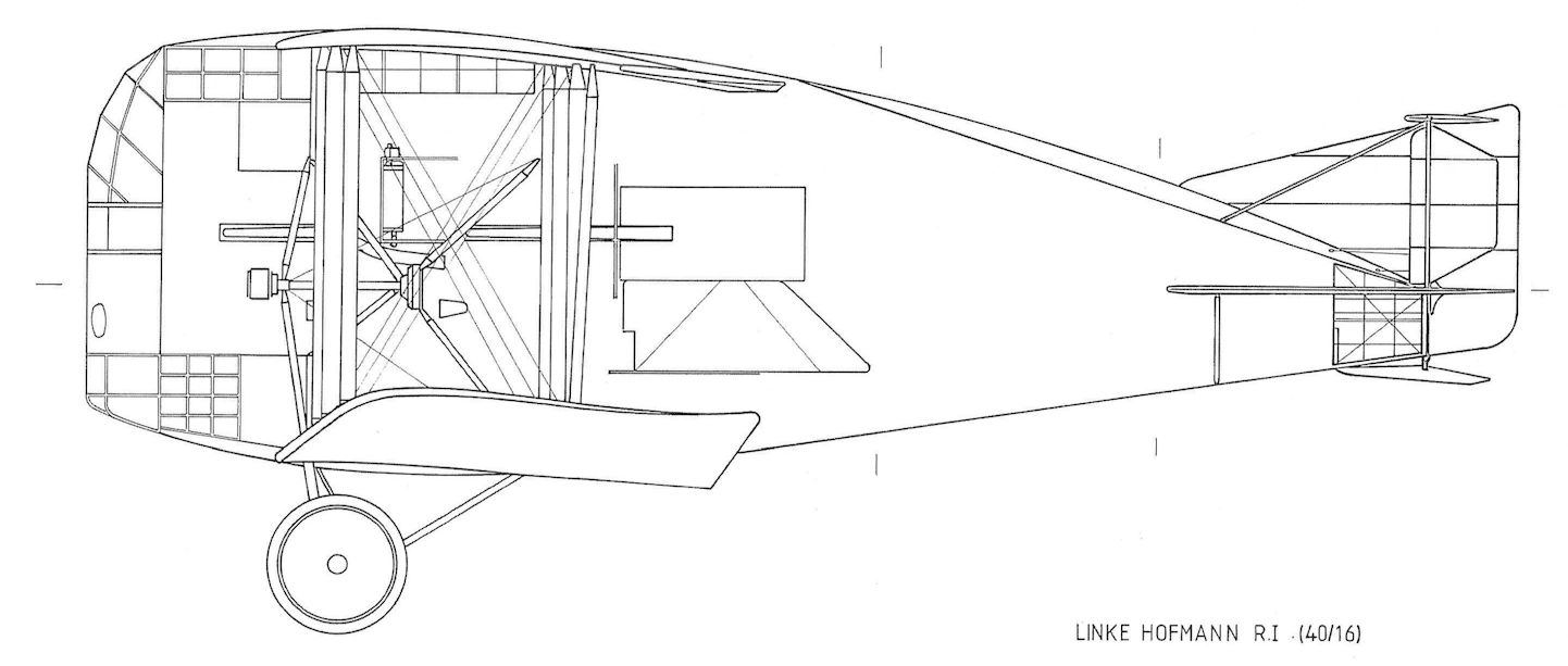
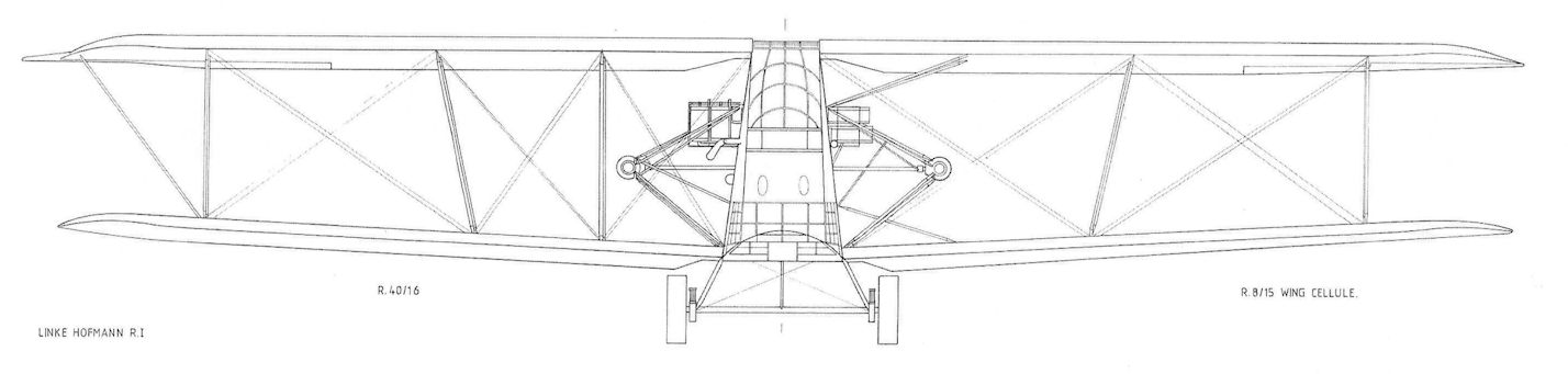
R.8 had two-bay wings of light structure with ailerons mounted on the upper wings only. The ailerons had inset aerodynamic balances. When the R.8 was destroyed during flight testing, Idflieg ordered an improved series, R.I 40-42/16. The wings of R.40 were greatly strengthened with 3-bay wing bracing and the ailerons had external horn aerodynamic balances.
The R.8 was built in 1916 and testing started in January 1917. It initially used steel wheels but these failed during taxi tests and were replaced by improved tires. The maiden flight of R.8 was in the spring of 1917. On May 10, 1917 R.8 crashed after two wings collapsed when flying at low altitude at full power. The crew survived except for a mechanic who ran into the flames. The root cause of the accident was weak wing structure. The weak wings had also caused problems in flight due to wing flexing.
R.I R.40-42/17 were ordered after the crash of R.8 with greatly strengthened wings. Other modifications compared to R.8 included new structure to hold the propellers, more efficient radiators, improved landing gear, provision for dorsal, ventral, and beam machine-gun positions, and a great reduction in the amount of Cellon covering. R.40 had good maneuvering and flying qualities although the performance was still unsatisfactory. The next two aircraft of the batch, 41/17 and 42/17, were almost ready for acceptance in January 1918 but as far as is known these were not completed and Idflieg abandoned further interest in the type.
Schutte-Lanz R.I 8/15 Specifications
Engine: 4 x 260 hp Mercedes D.IVa
Wing: Span 32.02 m
Wing Area 264 m2
General: Length 15.56 m
Height 6.78 m
Empty Weight 5800 kg
Loaded Weight 9000 kg
Maximum Speed: 140 km/h
Schutte-Lanz R.I 40/16 Specifications
Engine: 4 x 260 hp Mercedes D.IVa
Wing: Span 32.2 m
Chord, upper 5 m
Chord, lower 4.7 m
Wing Area 265 m2
General: Length 15.6 m
Height 6.7 m
Empty Weight 8000 kg
Loaded Weight 11,200 kg
Maximum Speed: 130 km/h
Climb: 3000 m 120 min.
The firm of Linke-Hofmann dealt with mechanical design and manufacturing, mostly locomotives and railway equipment in peace time, and in 1916 created a joint stock company, Linke-Hofmann Werke AG Abteillung Flugzeugbau, in the same premises. The firm commenced by repairing aircraft but by the end of the year they had acquired a licence to produce their own aircraft. It undertook to study giant planes (R-types) that used centralized engines, that is to say, united in the central fuselage.
During 1916 the firm repaired 80 machines and built 15 new aircraft. In 1917 the figures were 112 and 80; 1918 they were 80 and 20 respectively. This does not include R-types.
The following types were produced:
LFG Roland C.IIa (1 prototype + 52 production); Albatros C.Id and C.If (100 ordered but doubtful any were completed); Albatros C.III 75; Albatros C.X 50; Albatros B.IIa (about 150); and three R types - R.I 8/15 and 40/16 and R.II 55/17. The R.III was under construction but never finalised before the Armistice.
The firm commenced work with about 450 workmen and 18 staff. In 1917 the numbers had risen to 430 and 47 respectively, but in 1918 the workforce for the production of the R-types had been reduced to 130 men. Despite much experimental work done by the firm, tangible results were not achieved.
Linke-Hofmann R.I
Having been asked to design and build giant aircraft, Linke-Hofmann's first design was the distinctive R.I. The aircraft had a short, fat fuselage that completely filled the gap between its biplane wings, a configuration that research had shown had a high lift-drag ratio. This 'whale' design was used for low drag but the resulting performance and flight characteristics were mediocre despite its streamlining.
Given the military designation R.I 8/15, the R.I was powered by four reliable 260 hp Mercedes D.IVa engines that were installed in the fuselage. These were connected together in two pairs, one pair on each side of the fuselage mounted to connect to a drive shaft via a bevel gear. Each drive shaft drove a pair of propellers between the wings, one mounted forward as a tractor and the other aft as a pusher. Each drive shaft drove propellers on one side of the aircraft. The purpose of this complex arrangement was to enable all propellers to remain powered even in case of an engine failure. In this time of fixed pitch propellers, they could not be feathered to minimize drag if an engine failed. A windmilling propeller creates drag similar to an open parachute of the same diameter, and this drag meant a two-engine aircraft could not maintain altitude with an engine failure.
The nose of the R.I was extensively glazed and was deep enough to be divided into three levels. The pilots' cockpit was on the upper level with the radio operator's position behind them. The middle deck contained the engines and the lower deck housed the bombardier's cockpit and the four fuel tanks.
The rear of the fuselage was covered with Cellon. The purpose was to give partial invisibility of the airplane, a technology that was also tested on smaller aircraft and the final rebuild of the Staaken VGO.I. However, Cellon was shiny and reflected the light more than fabric, so increased the aircraft's visibility instead of reduced it. Cellon also expanded and shrank with temperature and humidity and turned yellow after prolonged exposure to sunlight. These problems eliminated further interest in Cellon covering, but R.8 used it.
R.8 had two-bay wings of light structure with ailerons mounted on the upper wings only. The ailerons had inset aerodynamic balances. When the R.8 was destroyed during flight testing, Idflieg ordered an improved series, R.I 40-42/16. The wings of R.40 were greatly strengthened with 3-bay wing bracing and the ailerons had external horn aerodynamic balances.
The R.8 was built in 1916 and testing started in January 1917. It initially used steel wheels but these failed during taxi tests and were replaced by improved tires. The maiden flight of R.8 was in the spring of 1917. On May 10, 1917 R.8 crashed after two wings collapsed when flying at low altitude at full power. The crew survived except for a mechanic who ran into the flames. The root cause of the accident was weak wing structure. The weak wings had also caused problems in flight due to wing flexing.
R.I R.40-42/17 were ordered after the crash of R.8 with greatly strengthened wings. Other modifications compared to R.8 included new structure to hold the propellers, more efficient radiators, improved landing gear, provision for dorsal, ventral, and beam machine-gun positions, and a great reduction in the amount of Cellon covering. R.40 had good maneuvering and flying qualities although the performance was still unsatisfactory. The next two aircraft of the batch, 41/17 and 42/17, were almost ready for acceptance in January 1918 but as far as is known these were not completed and Idflieg abandoned further interest in the type.
Schutte-Lanz R.I 8/15 Specifications
Engine: 4 x 260 hp Mercedes D.IVa
Wing: Span 32.02 m
Wing Area 264 m2
General: Length 15.56 m
Height 6.78 m
Empty Weight 5800 kg
Loaded Weight 9000 kg
Maximum Speed: 140 km/h
Schutte-Lanz R.I 40/16 Specifications
Engine: 4 x 260 hp Mercedes D.IVa
Wing: Span 32.2 m
Chord, upper 5 m
Chord, lower 4.7 m
Wing Area 265 m2
General: Length 15.6 m
Height 6.7 m
Empty Weight 8000 kg
Loaded Weight 11,200 kg
Maximum Speed: 130 km/h
Climb: 3000 m 120 min.
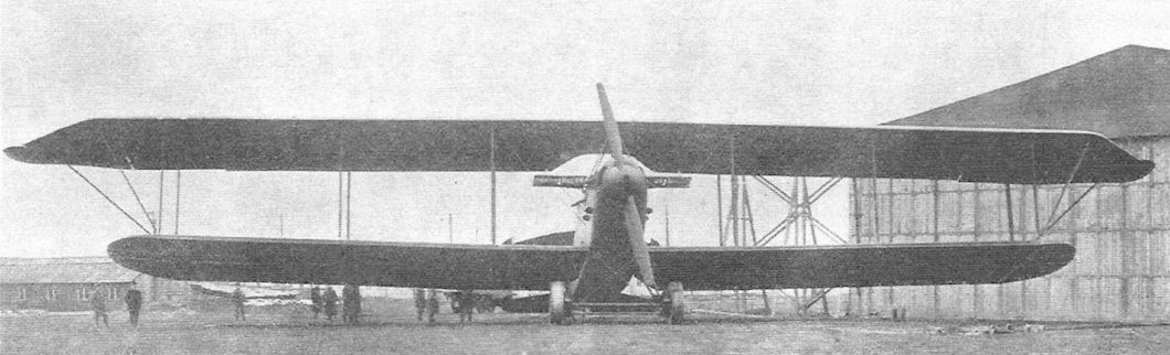
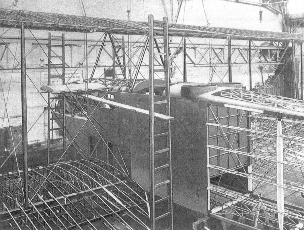
Completed Linke-Hofmann R.I R.8/15 on the factory airfield. The Linke-Hofmann R.I featured four 260 hp Mercedes D.IVa engines in the fuselage geared in pairs to drive outboard propellers via gears. The propellers were mounted as a pusher-tractor pair on each side between the wings. As usual for R-planes, a failed engine could be declutched from the drive system and repaired in flight. The airplane had an unusual silhouette and this example showed it with rear fuselage covered in transparent cellon as an early experiment with stealth technology. The first example crashed due to wing failure at low altitude; the second example shown had greatly strengthened wings but did not have good performance. (Peter M. Grosz collection/STDB)
Linke-Hofmann R.I R.8/15 metal landing gear. (Peter M. Grosz collection, STDB)
Linke-Hofmann R.I metal landing gear installation from the rear. (Peter M. Grosz collection, STDB)
Cellon-covered tail of the Linke-Hofmann R.I R.8/15. (Peter M. Grosz collection, STDB)
Linke-Hofmann R.I R.8/15 prior to installation of propellers. (Peter M. Grosz collection, STDB)
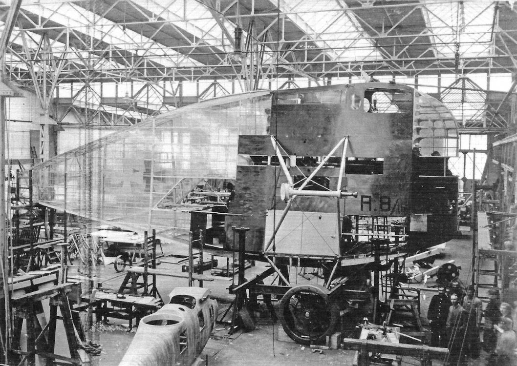
Linke-Hofmann R.I 8/15 during assembly, showing the Cellon skin covering.
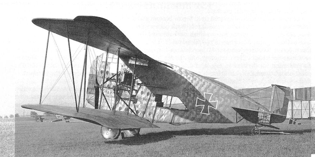
Linke-Hofmann R.I R.40/16 after completion. The rear fuselage is covered by standard, printed camouflage fabric.
Linke-Hoffman R.I R.40/16 of 1917, using four 260 h.p. Mercedes D.IVa engines carried inside fuselage. Remained a prototype bomber.
Linke-Hofmann R.I R.40/16 shows its unique appearance.
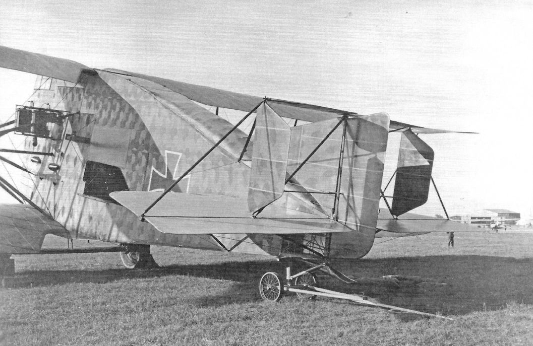
Linke-Hofmann R.I R.40/16; the tail is covered with printed camouflage fabric. (Peter M. Grosz collection, STDB)
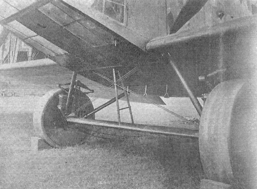
Linke-Hofmann R.I R.40/16 landing gear.
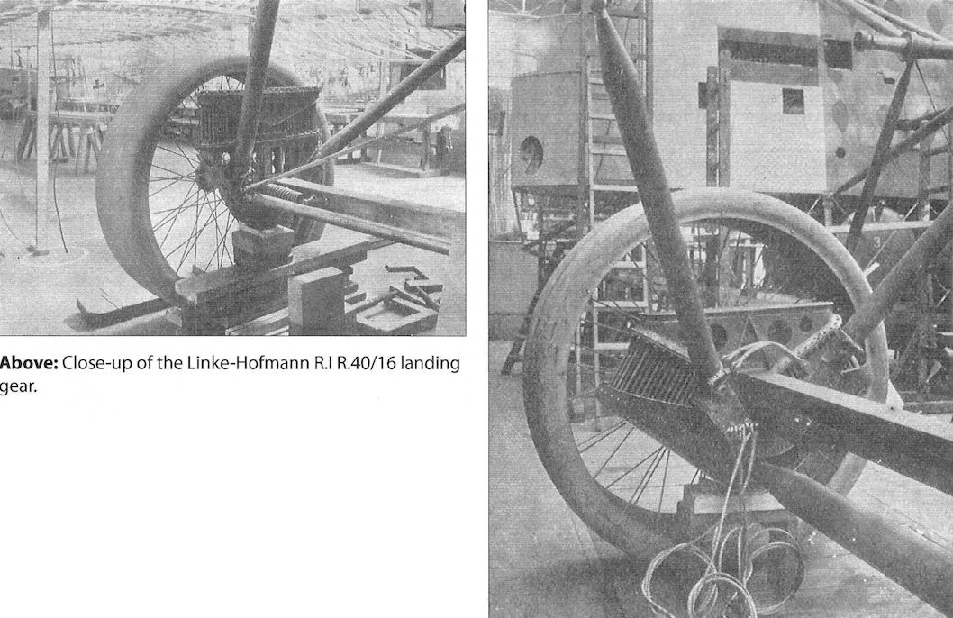
Close-up of the Linke-Hofmann R.I R.40/16 landing gear.
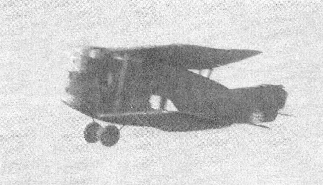
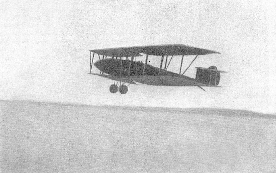
Linke-Hofmann R.I R.40/16 in flight.
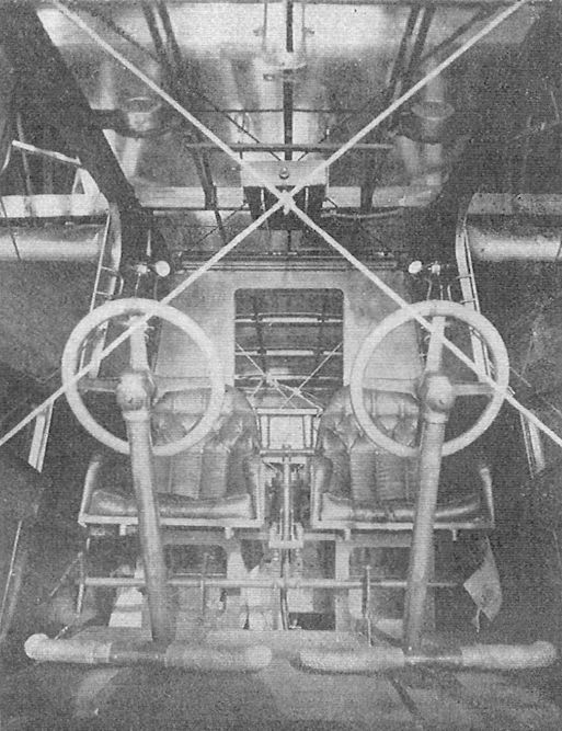
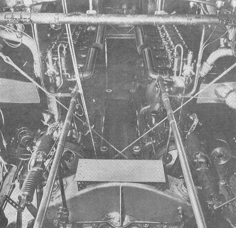
Linke-Hofmann R.I cockpit.
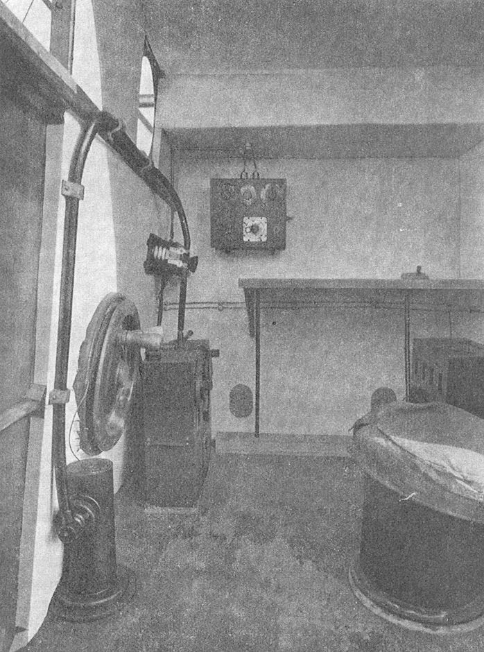
Linke-Hofmann R.I radio operator's position.
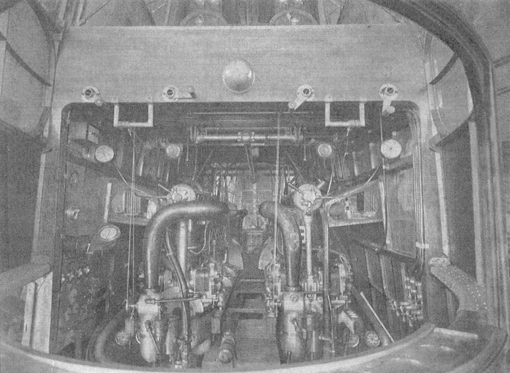
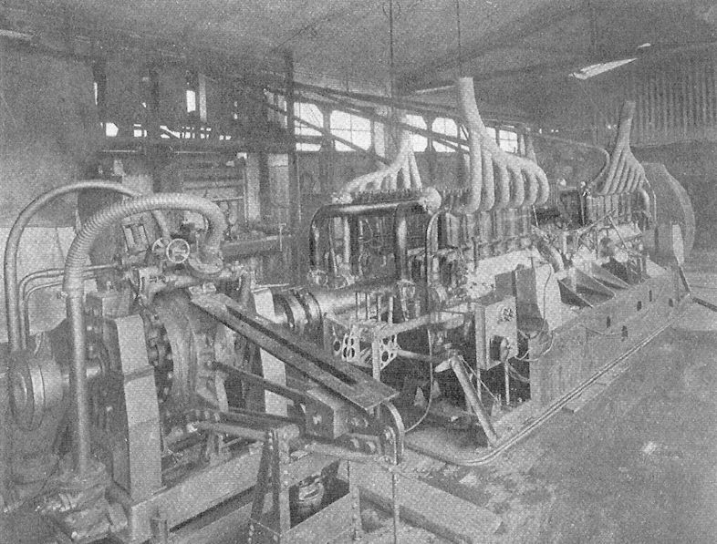
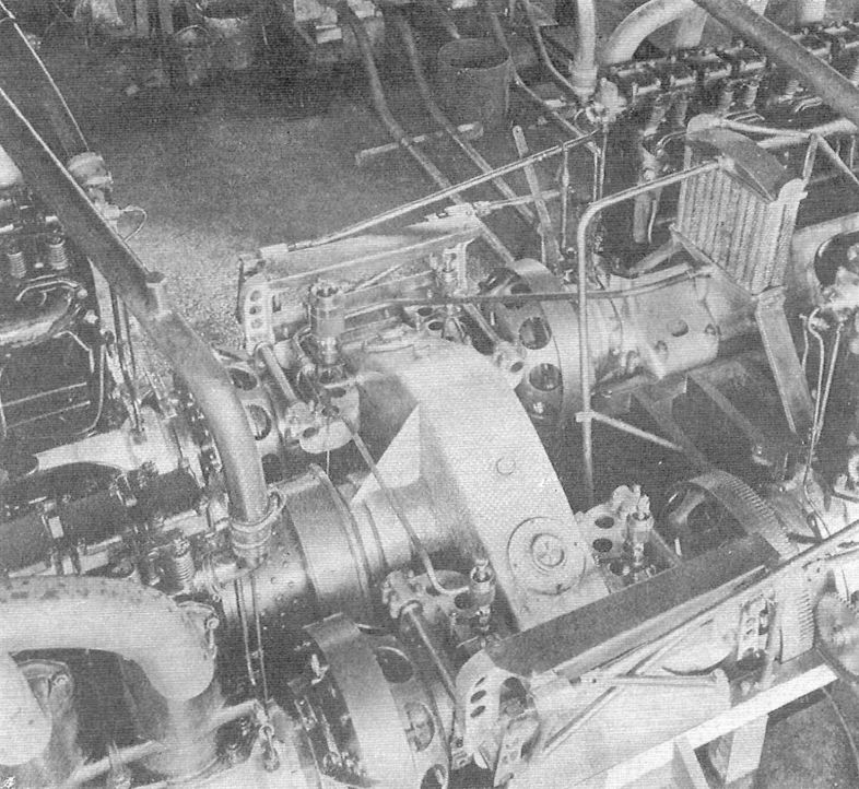
Engine room of the Linke-Hofmann R.I.
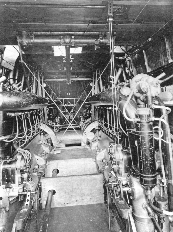
Linke-Hofmann R.I engine installation. (Peter M. Grosz collection, STDB)
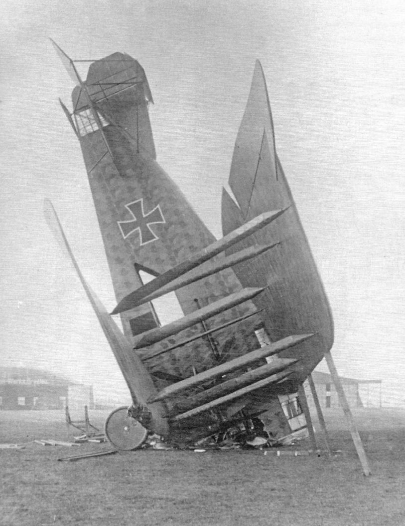
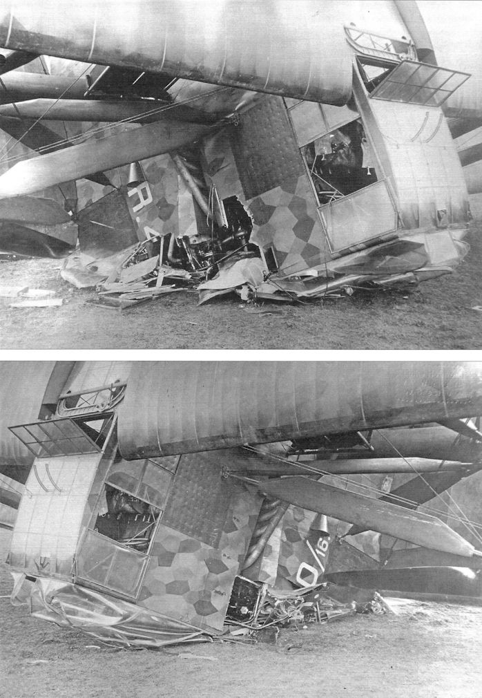
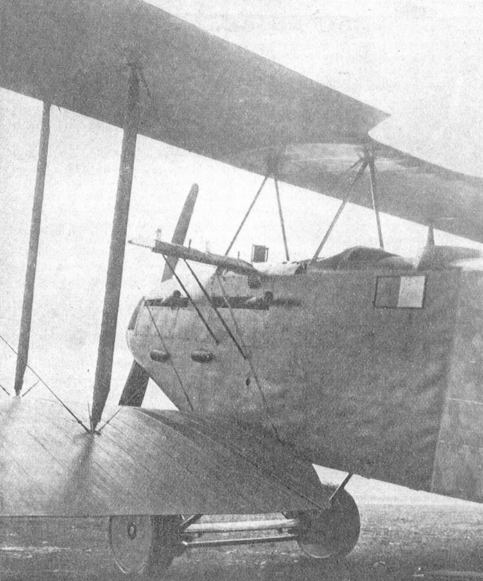
Linke-Hofmann R.I R.40/16 after a taxi accident.This brought the story of R.40 to an end. Note the damage to the cockpits in the nose. In particular the bombardier's position is destroyed. (Peter M. Grosz collection, STDB)
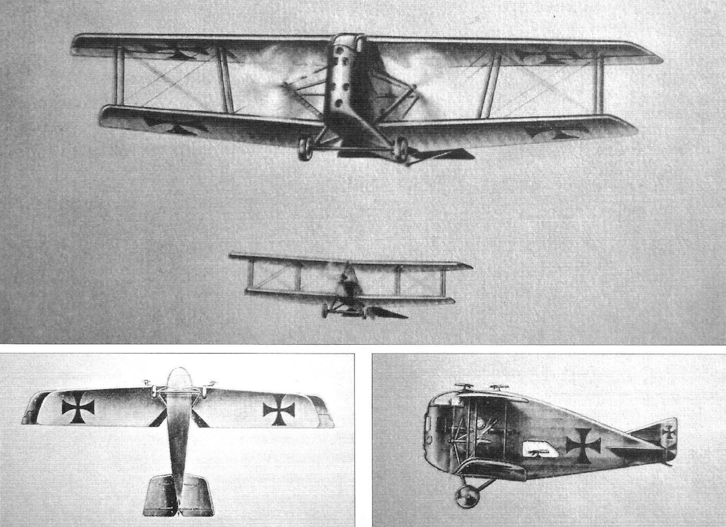
Drawings of the Linke-Hofmann R.I design before it was built
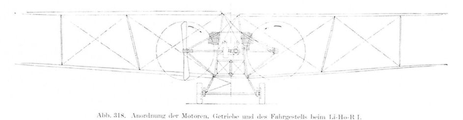
Drawing of the Linke-Hofmann R.I showing engine and radiator location.
Linke-Hofmann R.I
Linke-Hofmann R.I
Linke-Hofmann R.I
Linke-Hofmann R.I
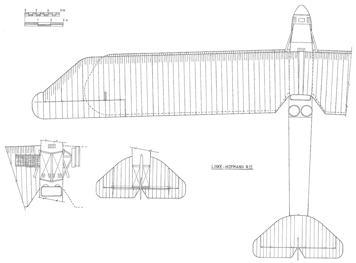
Linke-Hofmann R.II
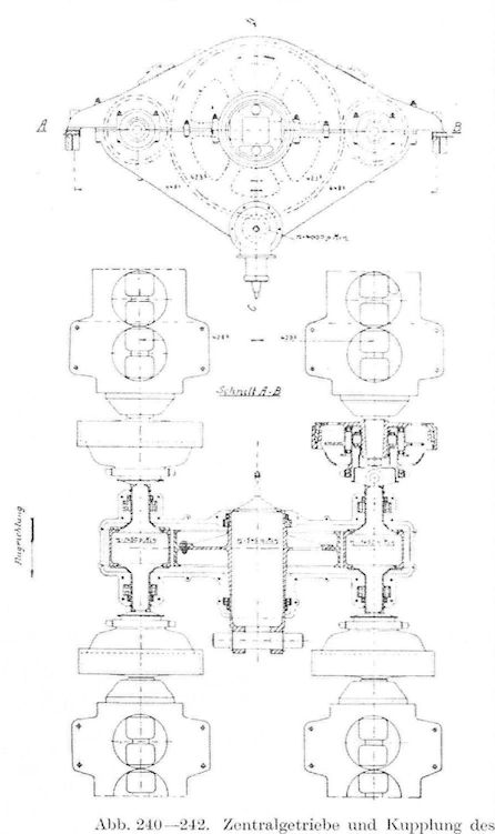
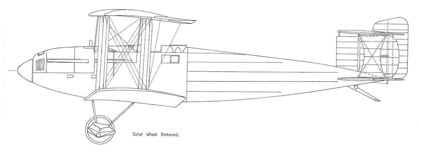
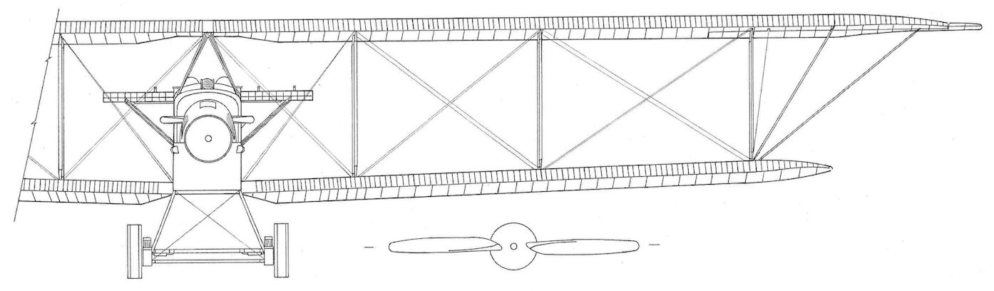
After the failure of the R.I, the R.II was a much more conventional design. The R.II airframe looked like a very large conventional biplane. The four coupled 260 hp Mercedes D.IVa engines were retained but now geared to drive a single propeller at the nose. Again, a pair of engines were mounted on each side of the aircraft, and they were attached to a single gearbox with 2 1/2 foot diameter drive gear that drove the single propeller via a 9-inch torque tube. A failed engine could be de-clutched from the gearbox. Two aircraft, R.55/17 and R.56/17, were ordered.
The coupled engines were extensively tested on a factory test stand. Careful design and construction made the drive system very reliable. For one thing, the drive system was simpler and more robust than that of the R.I.
The radiators were mounted as small stub wings between the main wings. The forward fuselage was plywood covered and the aft fuselage was covered with printed camouflage fabric. The pilot's cockpit was located below the upper wing trailing edge and two dorsal gunners were mounted aft of this cockpit. The wings were constructed of wood with fabric covering. The landing gear was strong and simple, resembling that of much smaller airplanes. The wheels and tires were again made of metal.
Lack of a suitable propeller delayed its maiden flight from July 1918 when the airframe was scheduled to be complete to January 1919. The large propeller rotated at 545 RPM compared to 1200-1400 RPM of smaller aircraft with no reduction gear. A box-like structure under the fuselage shown in drawings was planned as a semi-rectratcable ventral turret. However, it was not fitted to R.55. R.55 was easy to fly and had good flying characteristics. This was due to its conventional configuration and the fact its controls were placed in ball-bearings to minimize control friction. Despite its huge size, the R.55 could be flown with one hand during gusty weather. The R.II could carry a maximum useful load of 7,000 kg, impressive for the time. Cruising on two engines it was calculated that flights up to 9 1/2 hours long were possible.
The R.56 was nearly complete at the Armistice but was not finished and never flew. The R.56 was planned to use a Brown-Boveri supercharger geared from the rear of the central spur gear to increase climb and ceiling.
Schutte-Lanz R.II Specifications
Engine: 4 x 260 hp Mercedes D.IVa
Wing: Span, upper 42.16 m
Span, lower 33.96 m
Chord 4.8 m
Wing Area 320 m2
General: Length 20.32 m
Height 7.1 m
Empty Weight 8000 kg
Loaded Weight 12,000 kg
Maximum Speed: 130 km/h
Climb: 1000 m 8 min.
2000 m 20 min.
3000 m 45 min.
Ceiling 3200 m
Duration: 7 hours
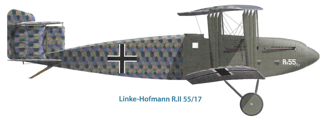
Linke-Hofmann R.II 55/17
R.II R.55/17 under construction showing the arrangement of the four 260 hp Mercedes D IVa engines.
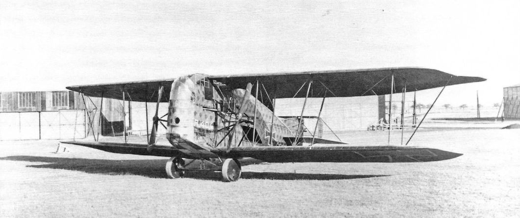
Linke-Hofmann R.II R.55/17 was configured like a much smaller, conventional biplane with a single propeller. This made the power train more reliable and helped ensure good flying qualities.
Linke-Hofmann R.II R.55/17 was configured like a much smaller, conventional biplane with a single propeller. This made the power train more reliable and helped ensure good flying qualities.
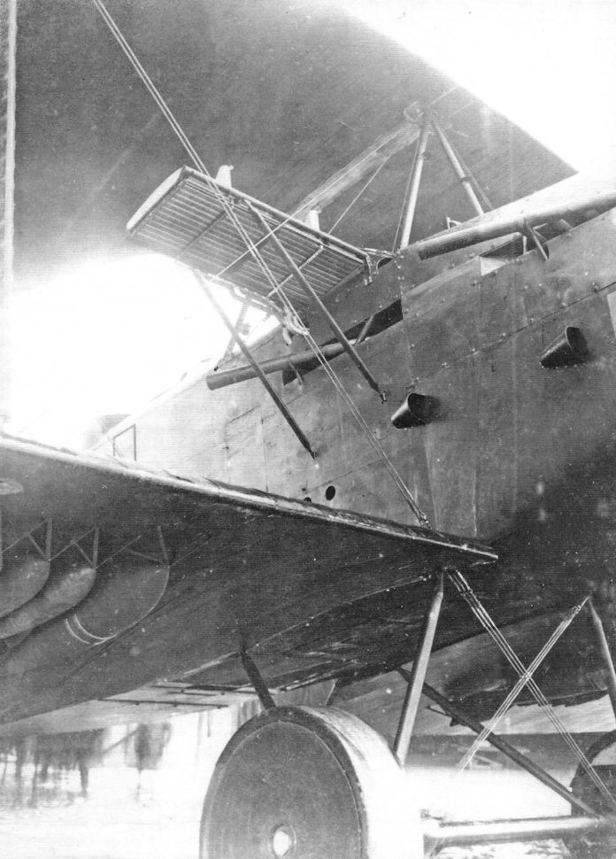
Close-up of Linke-Hofmann R.II R.55/17 showing the starboard radiator and bombs attached under the wing. (Peter M. Grosz collection, STDB)
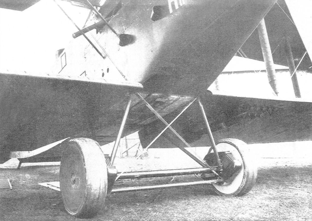
Linke-Hofmann R.II landing gear details and under-wing bombs mounted.
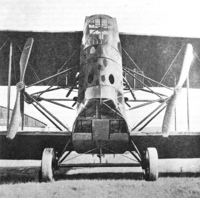
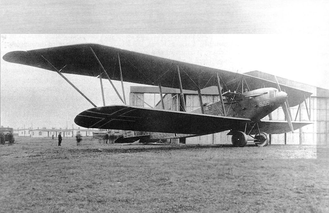
This front view of the Linke-Hofmann R.II R.55/17 shows its overall clean lines.The large wings had 3 1/2 bays of bracing.
Linke-Hofmann R.II R.55/17 after wings were mounted. The port radiator is clearly visible, as is the simple, robust metal landing gear. Printed camouflage fabric covered the rear fuselage while the nose was covered with plywood. The port rear gunner's position protrudes above the fuselage just forward of the fabric section. The exhausts of the two port engines show were they are located.
Linke-Hofmann R.II R.55/17 in flight.
The Linke-Hofmann R.II R.55/17 had a biplane tail with three fins and rudders. (Peter M. Grosz collection, STDB)
Linke-Hofmann R.II R.55/17 before wings were mounted. The starboard radiator is clearly visible, as is the simple, robust metal landing gear. Printed camouflage fabric covered the rear fuselage. The starboard rear gunner's position protrudes above the fuselage just forward of the fabric section. The nose section was covered with plywood.
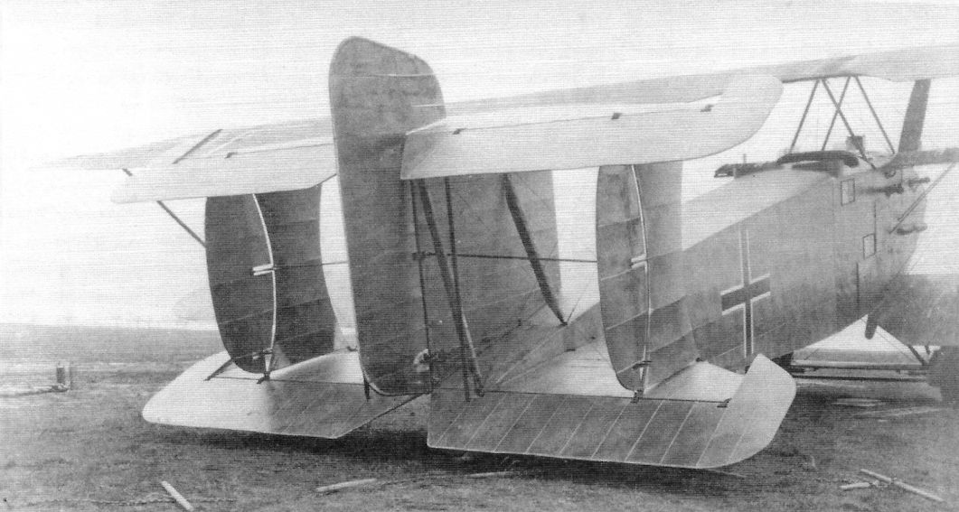
The camouflage pattern and taped stringers are clearly seen in this view of the dismantled Linke-Hofmann R.II. Note the propeller broken during ground tests.
The camouflage pattern and taped stringers are clearly seen in this view of the dismantled Linke-Hofmann R.II. Note the propeller broken during ground tests.
Linke-Hofmann R.II landing gear details, with shock-absorbers and under-wing bombs mounted.
Linke-Hofmann R.II drive gear.
Linke-Hofmann R.II R.55/17 under construction in the factory. (Peter M. Grosz collection, STDB)
Linke-Hofmann R.II under construction showing its structure.
Linke-Hofmann R.II drive train under construction.
Close-up of Linke-Hofmann R.II drive train.
Linke-Hofmann R.II drive train.
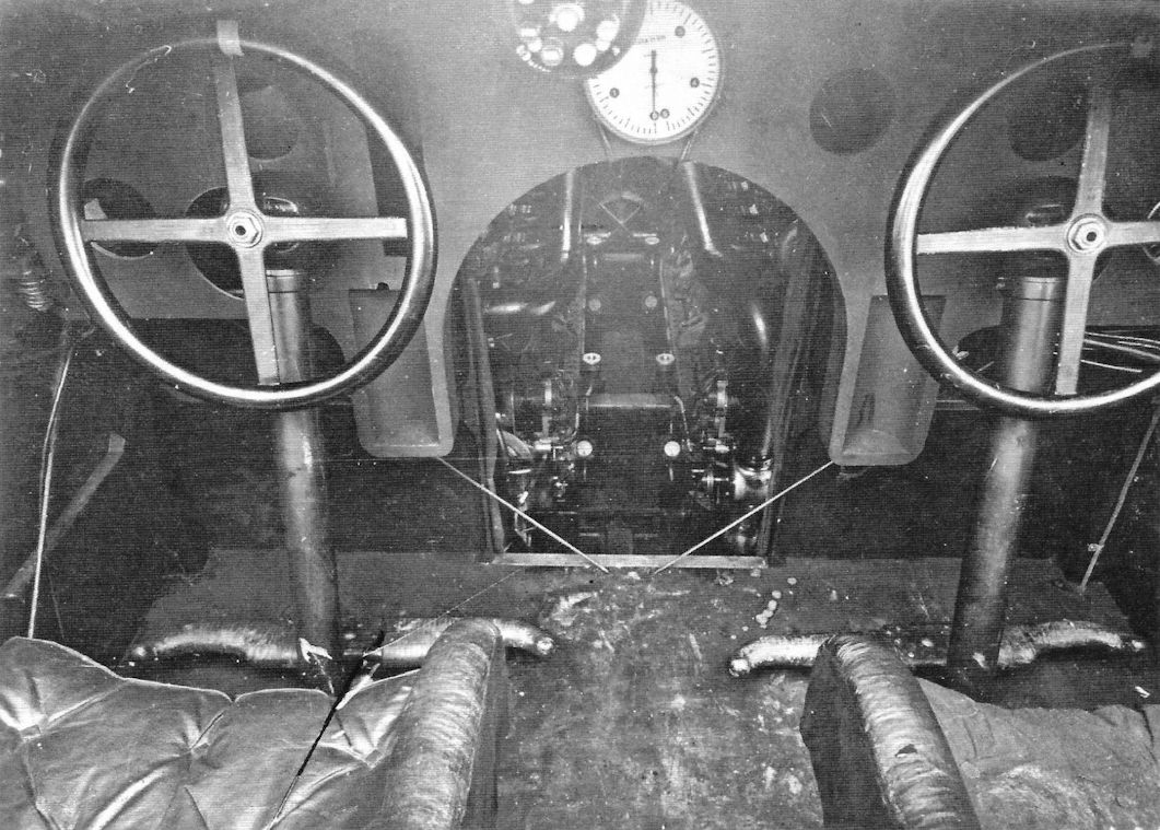
Cockpit of the Linke-Hofmann R.II R.55/17 during construction. (Peter M. Grosz collection, STDB)
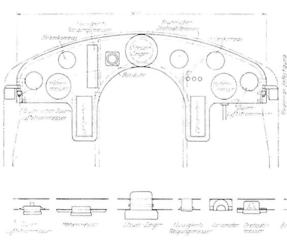
Drawing of the Linke-Hofmann R.II instrument panel.
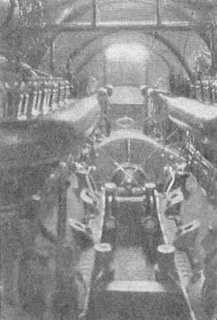
Linke-Hofmann R.II engine room
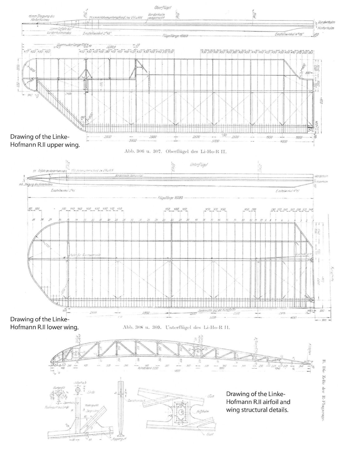
Drawing of the Linke-Hofmann R.II upper wing, lower wing, airfoil and wing structural details.
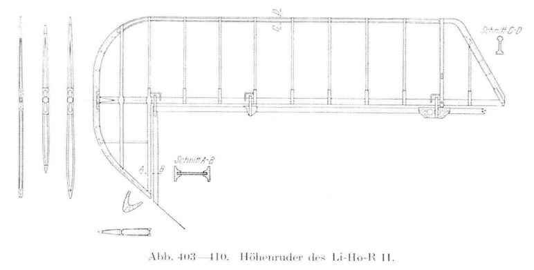
Drawing of the Linke-Hofmann R.II elevator.
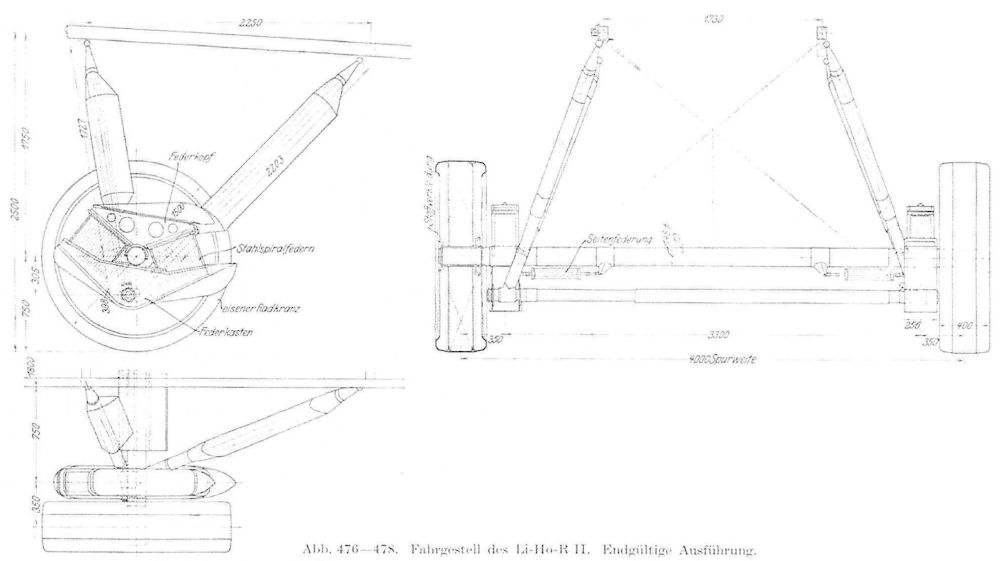
Drawing of Linke-Hofmann R.II landing gear.
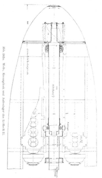
Drawing of nose of Linke-Hofmann R.II showing drive shaft and propeller connection.
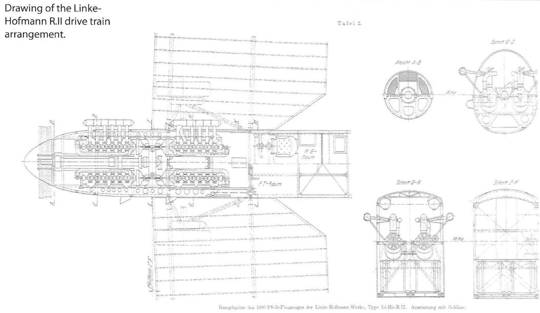
Drawing of the Linke-Hofmann R.II drive train arrangement.
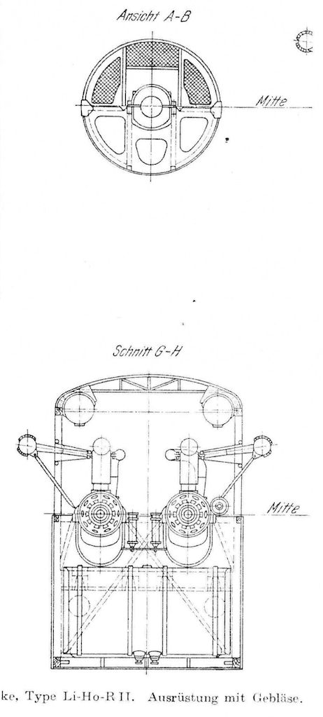
Cross-section of Linke-Hofmann R.II drive train arrangement showing the engines and exhausts.
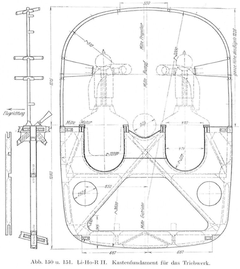
Cross-section of Linke-Hofmann R.II drive train arrangement.
Plan drawing of Linke-Hofmann R.II drive train arrangement showing the engines and gears.
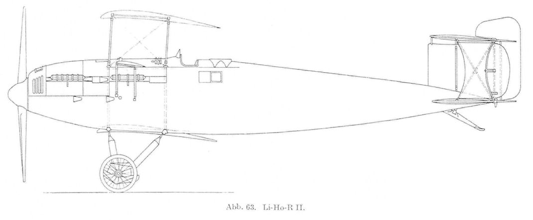
Side-view drawing of the Linke-Hofmann R.II.
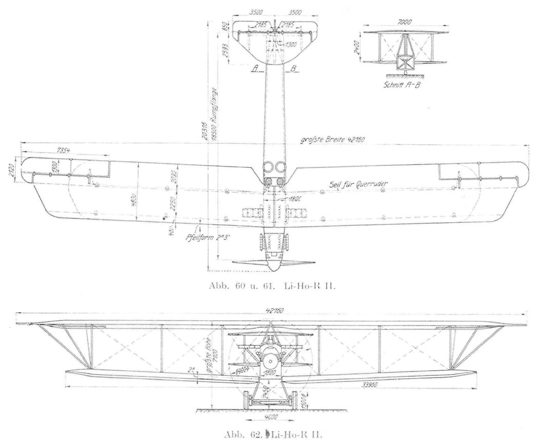
Dimensioned drawing of the Linke-Hofmann R.II.
Linke-Hofmann R.II
Linke-Hofmann R.II
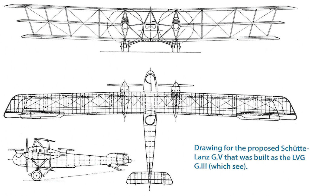
Drawing for proposed Schutte-Lanz G.V that was built as the LVG G.III.
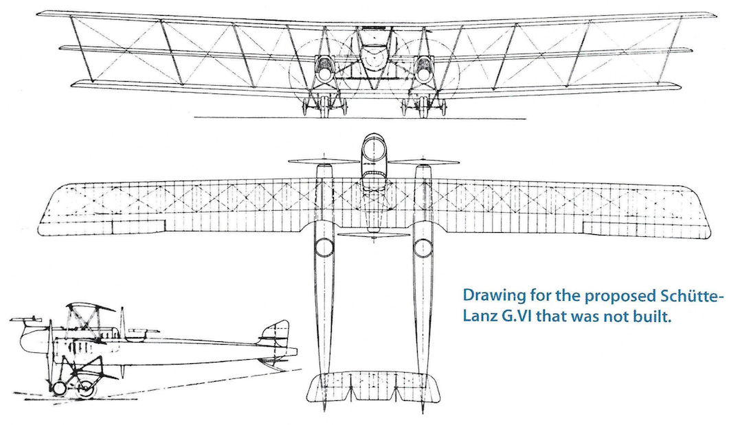
Drawing for proposed Schutte-Lanz G.VI that was not built.
Markische
The Markische Flugzeug-Werke G.m.b.H. company was founded in Teltow on 4 December 1913, by Herr Director Eckelmann, and in June 1914, was registered as a company.
The Company owned about 97,000 m2 of land at Golm-in-der Mark which was used as an aerodrome. A building for construction and repair occupied about 24,000 m2 where they built Rumpler C.I trainers under licence. Staff rose from 6 workmen in 1913 to 1,700 in 1917/1918.
From July 1914 to September 1916, repair work was carried out, reaching 28 repaired machines per month. The license to build 100 Rumpler C.I Mark) school machines was obtained that month. By the end of 1916 a new contract for 200 Rumplers was the first of three of which 135 were delivered that year. In January and February 1918, abut 80 new machines were delivered of the 300 ordered. About 66 were unfinished at the Armistice.
Wilhelm Hillman was an engineer with Schutte-Lanz and was in the United Kingdom to learn to fly the Sopwith Bat Boat flying boat prior to license manufacture of the type by Schutte-Lanz, but was recalled to Germany as war was imminent. He designed the only original aircraft from the Markische company, their D.I fighter.
The Markische D.I was powered by the 185 hp Benz Bz.IIIbo V-8 engine. When the company was inspected by the IAACC there were only two aircraft and 28 engines at the plant. After the war, the firm left aviation and changed its name in 1919 to Markische Industrie-Werke G. M. b. H and started repairing railway cars and manufacturing furniture.
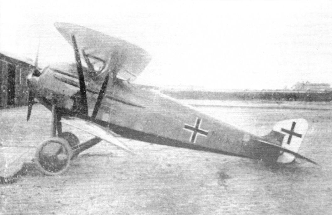
The only original Markische design was the Markische D.l fighter. It was powered by an experimental 185 hp Benz V-8 Bz.IIIbo engine. The aircraft had V-struts and single-spar lower wing; this configuration was aerodynamically suspect and was obsolete by the time the prototype was built in 1918. (Peter M. Grosz collection, STDB)
Mercur
Mercur-Flugzeugbau GmbH of Berlin - Neukolln and Berlin-Johannisthal, was founded under this name on 15 April 1915, as an equal partnership between the then current owner Herr Romeo Wankmuller and the managers, Herman Tradowski and Herr Tiegs. Later, on 7 March 1917, an associated company, the Mercur-Motorenbau GmbH was formed to construct aeromotors.
The company had a timber treatment mill, a factory with a separate aircraft repair branch, and a flying school at JohannisthaL An idea of the scope of the works is given by the increase in the size of the workshops:
June 1913 2,170 m2
October 1916 4,120 m2
February 1917 7,250 m2
May 1917 9,520 m2
September 1917 13,764 m:
The company was concerned with the sale of new aircraft and repairs to damaged aircraft and the manufacture of mainplanes and replacement parts.
In the months from October 1916 to June 1918, the firm received orders for the following aircraft:
1916 100 Alb B.II
1917 100 Alb B.II
1917 200 Alb B.II
1917 50 Alb B.II
1917 250 Alb C.Ib
1918 100 Alb C.Ib
The company repaired almost 600 aircraft during the time it was operational, these were Albatros, LFG, Rumpler, and Aviatik types. The repair of mainplanes was carried out to a lesser extent although over 117 were so treated. By the end of 1916 the firm was well established and by June 1918, had an income of 4,062,417 Marks. By June 1918 they employed 1,023 workers.
From 3 January 1917, the chief designer of the Mercur firm was Ing. Fritz Hildebrand. Technical direction was in the hands of Herr Martin Rollfa. The Science Director was Herr Professor Dr. Albert Einstein, and the chief pilots for the firm were Herr Otto Reichert and Otto Breitbeik.
The firm began to experiment with its own aircraft from the summer of 1917. The first was a fighter that was not accepted. Experiments were made with aerofoils of various characteristics.
The firm also commenced work on torpedo aircraft but the machine was never completed.
The status of the company's aircraft proposals was as follows:
1. Monoplane Fighter I (KE.II)
This machine left the factory in March 1918 and was erected but flight performance was disappointing and no further development took place.
2. Marine Torpedo Aircraft
This project was authorized after detail design and estimates of performance were submitted to the Navy's Design Directorate. The aircraft was under construction but was never completed.
3. Single-Seat Fighter II (CL.II)
The drawings for this project were completed by the time the engine, the 200 PS Benz Bz.IIIbo (Overcompressed), was to be installed. The engine was delivered on 22 March 1918, and on 4 April was given a test run.
4. Single-seat Biplane (D)
Although this project was nearing completion in mid-1918, the fuselage was never completed and much work was required to complete the aircraft.
5. Monoplane Fighter III
This project was abandoned.
6. Single-seat Monoplane Fighter IV
This aircraft was the last single-seat machine to be projected.
7. Riesenflugzeug Aircraft
Although projected the detail design was never completed. The aircraft was to be armed with six machine guns and to be powered by four engines, each of 260 PS, had an eight-man crew and a number of 2,000 kg bombs.
The company also produced the Mecur Kinergometer that was put into production.
A 350 PS aeromotor, similar in design and construction to an engine in production, but of a larger size, was built in 1918. The war ended before it could be tested by ZAK.
A two-cylinder aeromotor was built and tested and developed about 1 1/2 PS. The unit was not only small and manageable, but very simple in construction and with few complicated parts and hence a cheap machine. It was particularly good for wireless telegraphy and the operation of pumps and agricultural machinery.
Another device that the company developed was a motorized plough. The design and drawings were ready but production had not commenced when the war ended. The plough was to be about 6 to 8 PS initially with all components accessible for service.
Naglo
Built by the Naglo Werft of Pichelsdorf near Berlin, apparently the Naglo D.I quadraplane was designed on the basis of 'more is better'. The retrogressive quadraplane wing cellule was added to a fuselage derived from the Albatros D.V.
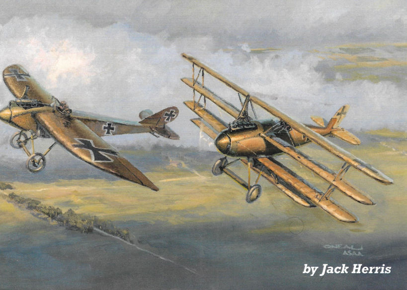
The Naglo D.II biplane was developed from the D.I and may have used the same fuselage. The D.II was evaluated in conjunction with the Second Fighter Competition and debriefing notes indicate it was to be modified and re-evaluated. Powered by a Mercedes D.III engine, it was intended to carry the standard German fighter armament of two machine guns. Official type testing was done 24 May 1918, and evaluation pilots praised the construction and workmanship but wanted improved flying qualities. Designed by Ing. Gnadig, who was employed by Albatros at the time, its appearance resulted in his termination for conflict of interest and the prototype was rejected at the request of Albatros. The pylon for attaching the lowest wing was built into the fuselage. No performance data has survived.
Naglo D.I Quadraplane Specifications
Engine: 160 hp Mercedes D.III
Wing: Span 9.00 m
Area 22.40 m2
General: Empty Weight 724 kg
Flying Weight 914 kg
Built by the Naglo Werft of Pichelsdorf near Berlin, apparently the Naglo D.I quadraplane was designed on the basis of 'more is better'. The retrogressive quadraplane wing cellule was added to a fuselage derived from the Albatros D.V.
The Naglo D.II biplane was developed from the D.I and may have used the same fuselage. The D.II was evaluated in conjunction with the Second Fighter Competition and debriefing notes indicate it was to be modified and re-evaluated. Powered by a Mercedes D.III engine, it was intended to carry the standard German fighter armament of two machine guns. Official type testing was done 24 May 1918, and evaluation pilots praised the construction and workmanship but wanted improved flying qualities. Designed by Ing. Gnadig, who was employed by Albatros at the time, its appearance resulted in his termination for conflict of interest and the prototype was rejected at the request of Albatros. The pylon for attaching the lowest wing was built into the fuselage. No performance data has survived.
Naglo D.I Quadraplane Specifications
Engine: 160 hp Mercedes D.III
Wing: Span 9.00 m
Area 22.40 m2
General: Empty Weight 724 kg
Flying Weight 914 kg
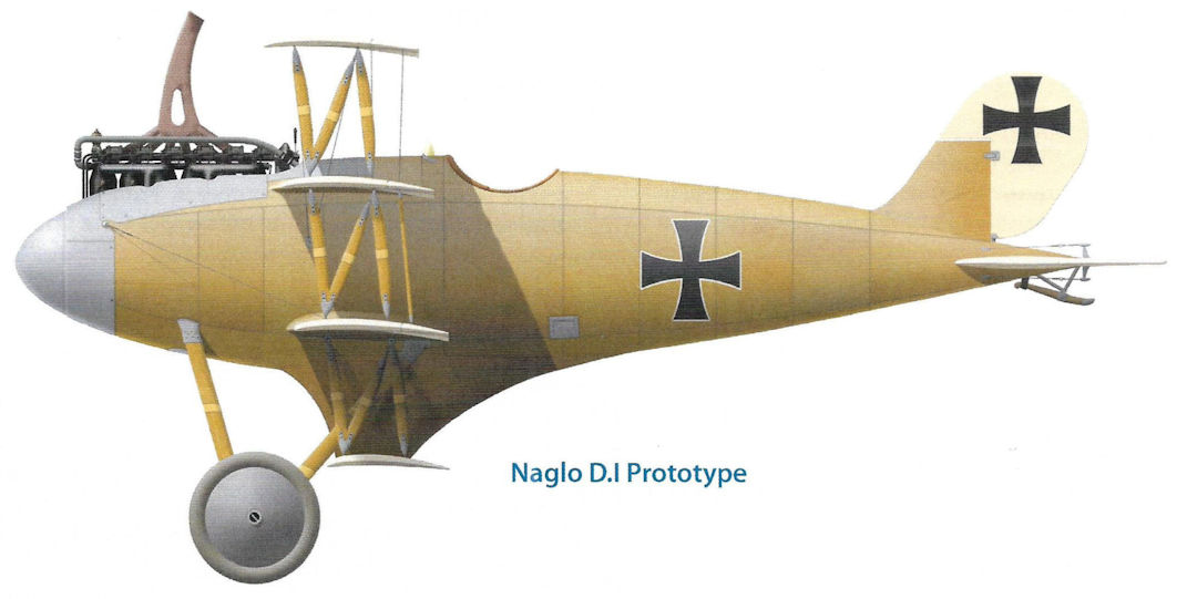
Naglo D.I Prototype
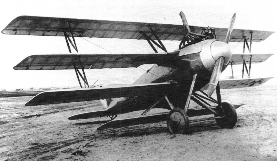
The Naglo D.I quadraplane fighter prototype. More wings increased both lift and drag, and fighters needed to be fast as well as maneuverable. Generally, multi-planes were slow.
The Mercedes D IIIa was the most popular fighter engine and was used in the bizarre Naglo D.I, a quadraplane inspired by the Albatros fighters.
The Mercedes D IIIa was the most popular fighter engine and was used in the bizarre Naglo D.I, a quadraplane inspired by the Albatros fighters.
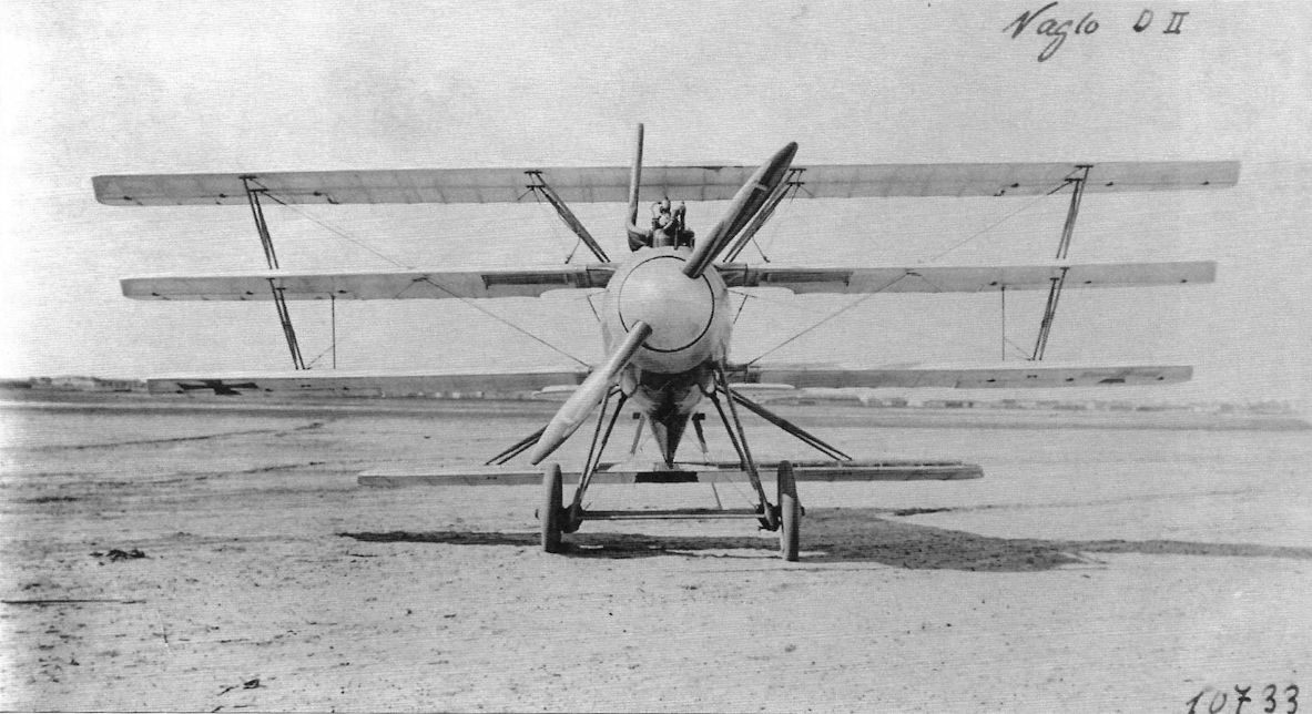
The Naglo D.I quadraplane fighter prototype. Span was 9 meters and it was powered by a 160 hp Mercedes D.III. Its biplane development the D.II, serial 1161/18, was evaluated in conjunction with the Second Fighter Competition. These photos are incorrectly marked 'D.II'. (Peter M. Grosz collection, STDB)
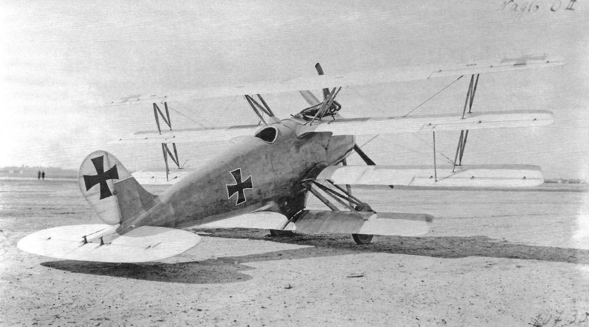
The Naglo D.I multiplane was one of the last gasps of Germany's 'Triplane Craze'. It was inspired by the Albatros D.V and designed by an engineer employed by Albatros; he was fired for his efforts. It featured excellent workmanship and poor design; the weight and drag of all its struts and wings ensured it had lower performance than the biplane that inspired it.

Closeup of the Naglo D.I fighter prototype. The radiators were airfoil type inset into the middle wing. (Peter M. Grosz collection, STDB)
The Naglo D.II fighter was a biplane development of the D.I quadraplane and competed at the Second Fighter Competition. This accurate Idflieg drawing shows it but no photos have survived. It may have used the fuselage of the D.I fitted with biplane wings as it retains the wing-mounting pylon under the fuselage. (Peter M. Grosz collection, STDB)
Naglo D.I
Naglo D.I
Naglo D.I
NFW
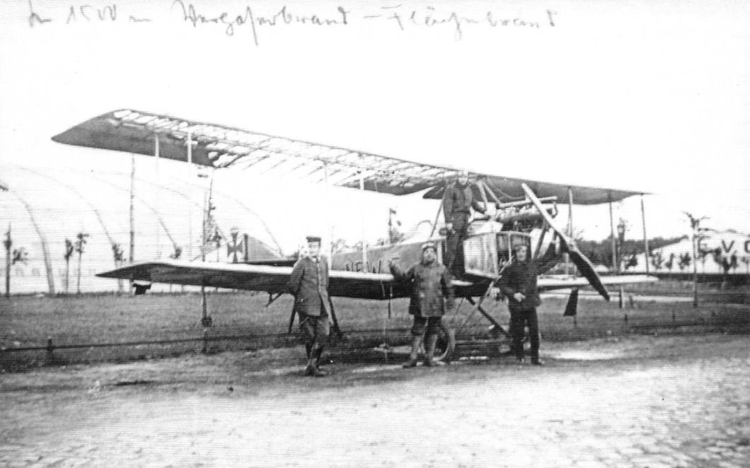
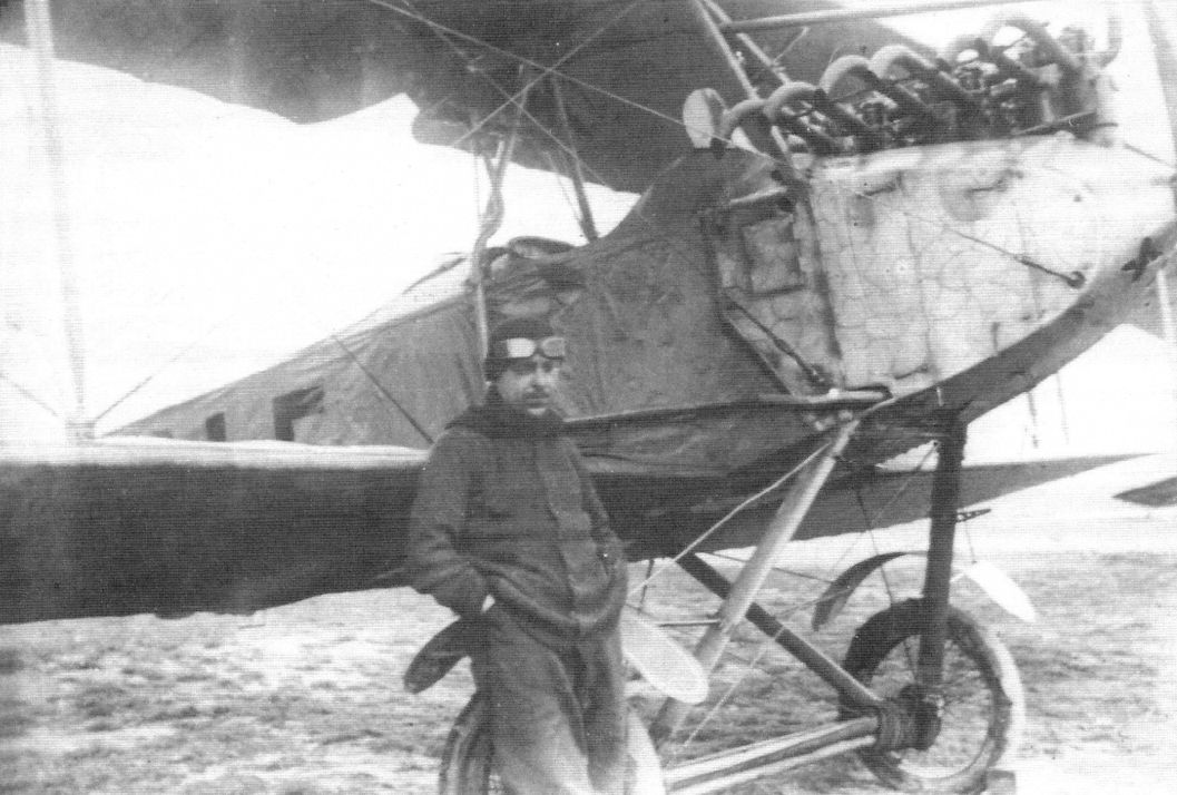
The National Flugzeug Werke (N.F.W.) located in Leipzig was founded in 1915 with the support of DFW from the Jeannin company. NFW had a flight training school at Johannisthal. They also dabbled in aircraft design and built the B.I unarmed biplane trainer for their flight school and several E-type monoplane fighter prototypes. From the few available photos, none of the prototypes were armed.
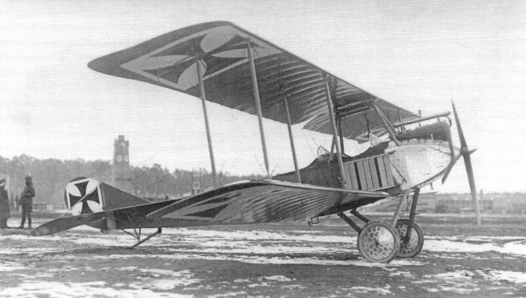
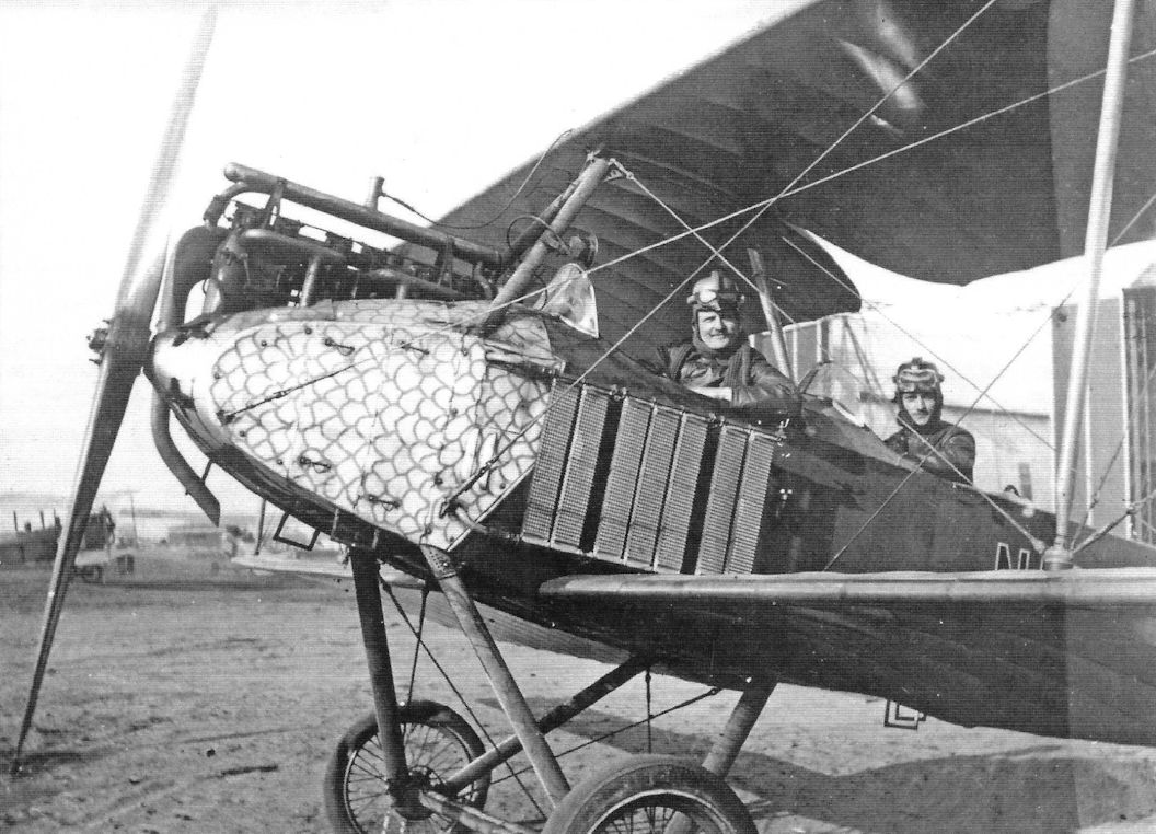
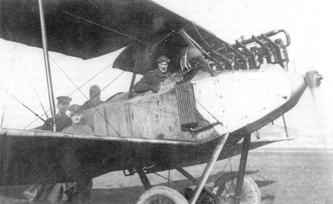
Small numbers of the NFW B.I trainers were built for the company's flight school but the exact number is not known. However, the NFW B.I did not serve in combat at the front. The engine was a 160 hp Mercedes D.III engine. This engine was in great demand for fighters so it is unusual that such a valuable engine was used for a trainer. The variety of radiator installations shown in photos likely resulted from maintenance over a prolonged period as the radiators available changed over time. As a limited production aircraft the spare parts available were also limited. No performance data is available.
The National Flugzeug Werke (N.F.W.) located in Leipzig was founded in 1915 with the support of DFW from the Jeannin company. NFW had a flight training school at Johannisthal. They also dabbled in aircraft design and built the B.I unarmed biplane trainer for their flight school and several E-type monoplane fighter prototypes. From the few available photos, none of the prototypes were armed.
Small numbers of the NFW B.I trainers were built for the company's flight school but the exact number is not known. However, the NFW B.I did not serve in combat at the front. The engine was a 160 hp Mercedes D.III engine. This engine was in great demand for fighters so it is unusual that such a valuable engine was used for a trainer. The variety of radiator installations shown in photos likely resulted from maintenance over a prolonged period as the radiators available changed over time. As a limited production aircraft the spare parts available were also limited. No performance data is available.
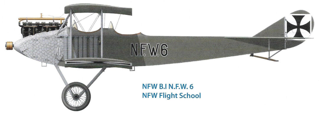
NFW B.I N.F.W.6 NFW Flight School
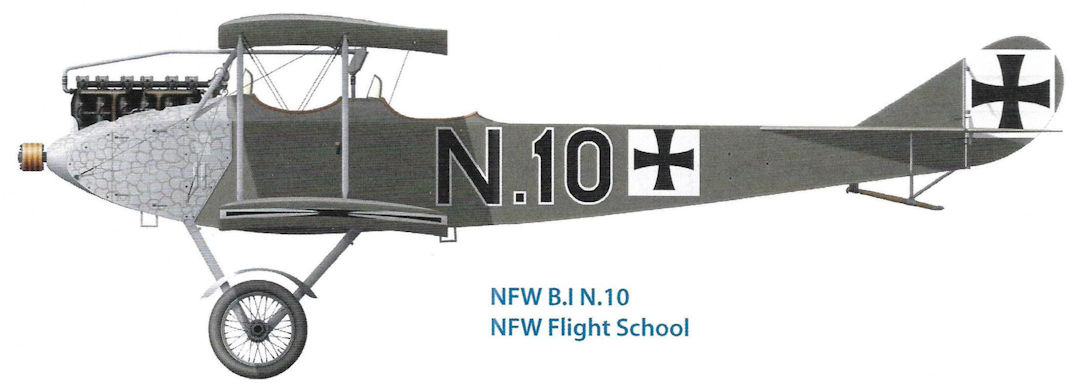
NFW B.I N.10 NFW Flight School
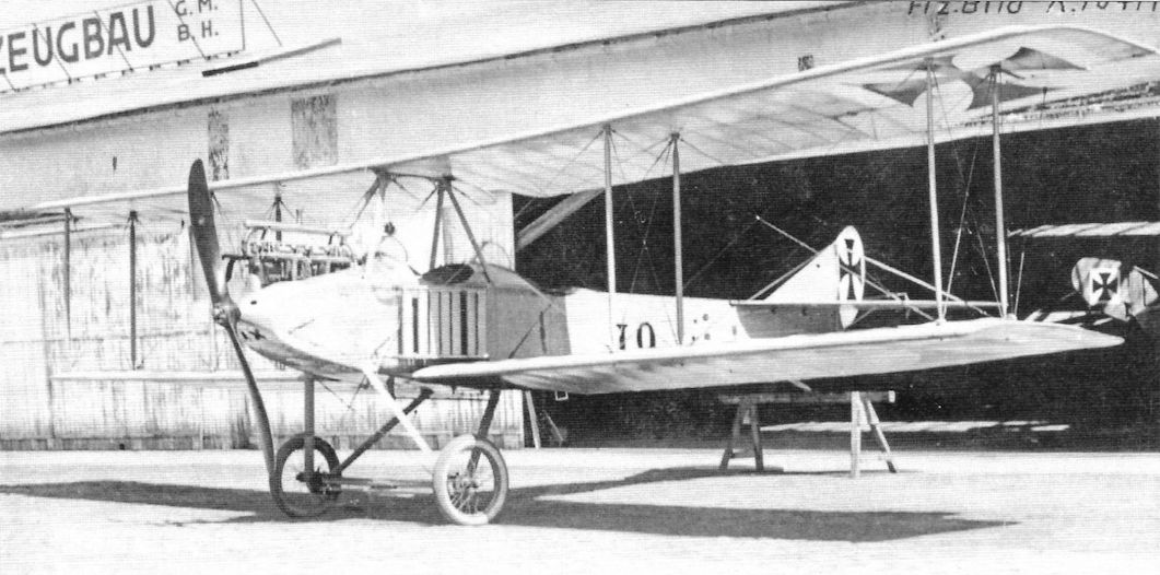
An NFW B.I at Johannisthal. Designed as a two-seat trainer, it was powered by a 160 hp Mercedes D.III. (Peter M. Grosz collection, STDB)
An NFW B.I at the NFW flight school. (Peter M. Grosz collection, STDB)
Given the great demand for the Mercedes D III to power fighters, it is surprising that it was used in the NFW B.I trainer. NFW built a small number of NFW B.I trainers to supply the NFW flight school at Johannisthal.
Given the great demand for the Mercedes D III to power fighters, it is surprising that it was used in the NFW B.I trainer. NFW built a small number of NFW B.I trainers to supply the NFW flight school at Johannisthal.
NFW B.I N.5 from the NFW flight school missing some wing fabric. (Peter M. Grosz collection, STDB)

NFW B.I trainer giving a demonstration at the NFW flight school.The aircraft has small side radiators. (Peter M. Grosz collection, STDB)
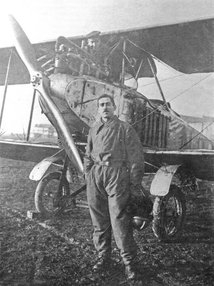
Student pilot and mechanic photographed with a NFW B.I with mud guards. The B.I has the original side radiators and sports the distinctive turned cowling panels (Peter M. Grosz collection, STDB)
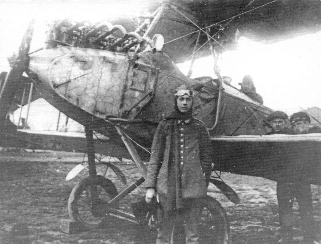
Flight student with his NFW B.I trainer fitted with mud guards. The flight instructor sits in the rear cockpit and the ground crew looks on at the right. An inelegant underwing radiator has replaced the ear radiator. The messy installation was certainly the result of maintenance with a limited parts inventory. (Peter M. Grosz collection, STDB)
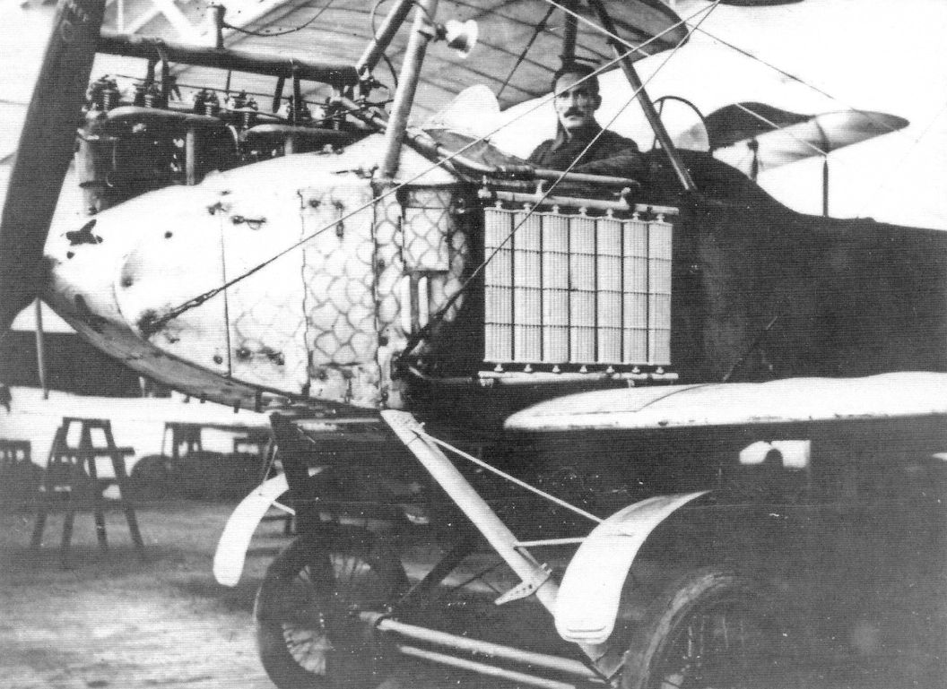
NFW B.I trainer photographed with pilot in the front cockpit in the hangar. Large side radiators are fitted. (Peter M. Grosz collection, STDB)
NFW B.I at the NFW flight school. This B.I has the original side radiators.The engine cowling has a distinctive 'turned' appearance. (Peter M. Grosz collection, STDB)
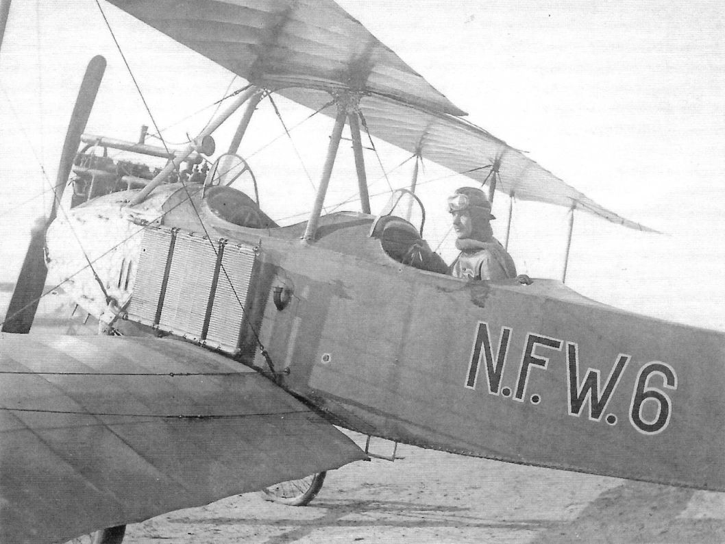
NFW B.I N.F.W.6 of the NFW flight school at Johannisthal. (Peter M. Grosz collection, STDB)
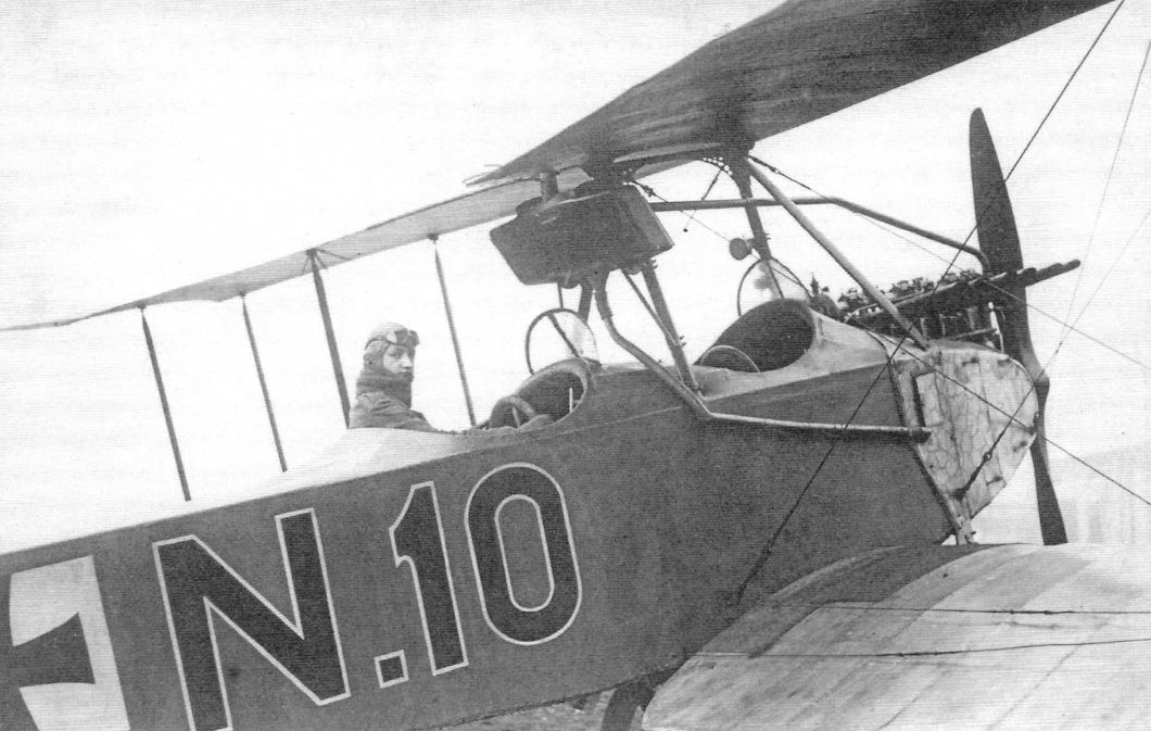
NFW B.I N.10 of the NFW flight school. This B.I has a newer radiator design under the top wing between the cockpits. The engine cowling has a distinctive 'turned' appearance. (Peter M. Grosz collection, STDB)
NFW B.I trainer photographed with pilot, trainee, and ground staff. This aircraft has small side radiators.The variety of radiators seen on the NFW B.I may be the result of maintenance needed to keep these trainers flying with whatever radiators were available. Production of the B.I may have also been at a slow rate over a prolonged period for the NFW flight school, with the result that the types of radiators available changed during production.
Flight student with his NFW B.I trainer fitted with mud guards. Note that the side radiators have been removed and a coolant pipe runs between the front of the engine and a radiator attached to the upper wing. This may have been the result of radiator replacement after side radiators were no longer readily available. (Peter M. Grosz collection, STDB)
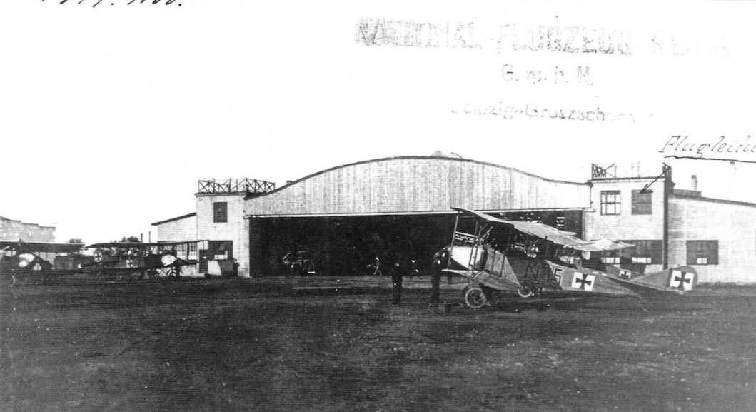
NFW B.I trainers at the NFW flight school. B.I N.15 is in the right foreground and does not have the original side radiators. (Peter M. Grosz collection, STDB)
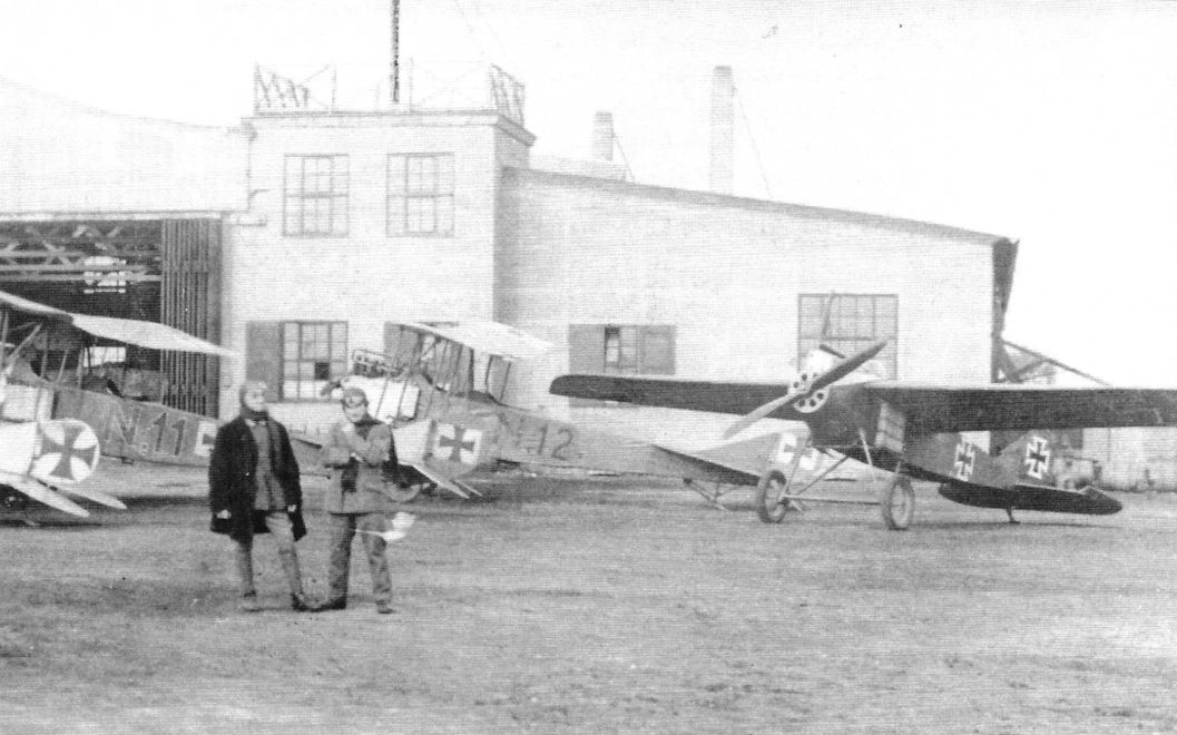
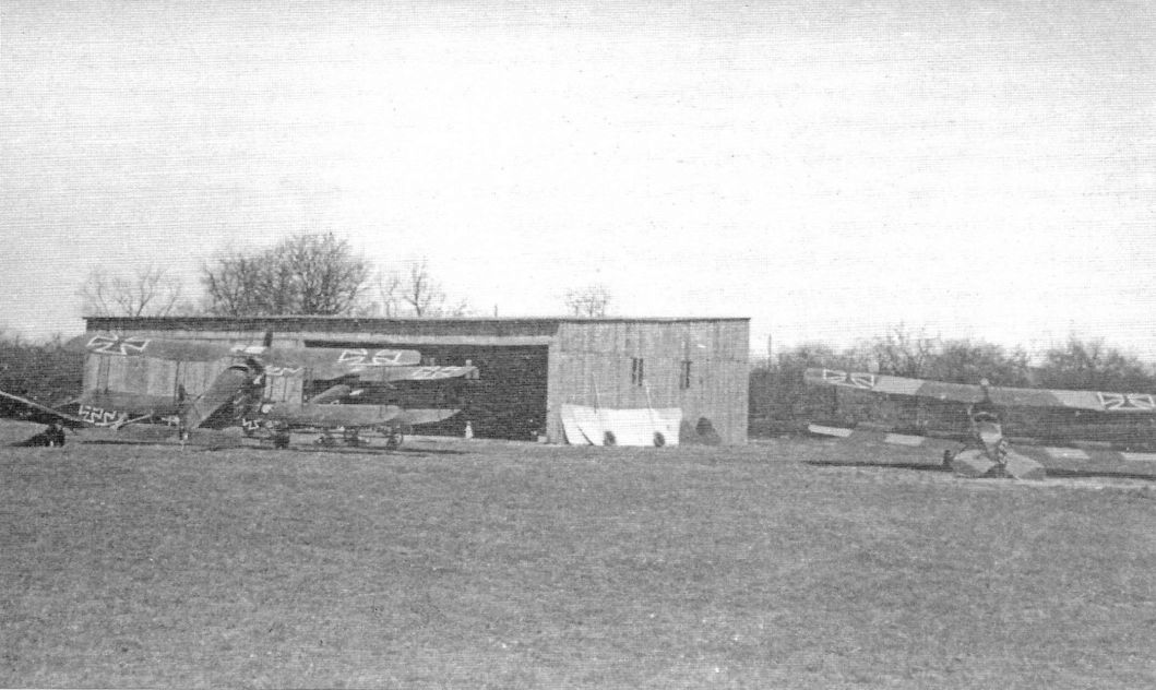
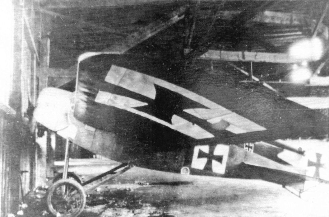
The NFW hangar at Johannisthal. NFW B.I trainers N.11 and N.12 are visible at left and the prototype NFW E.II is at right without its spinner. (Peter M. Grosz collection, STDB)
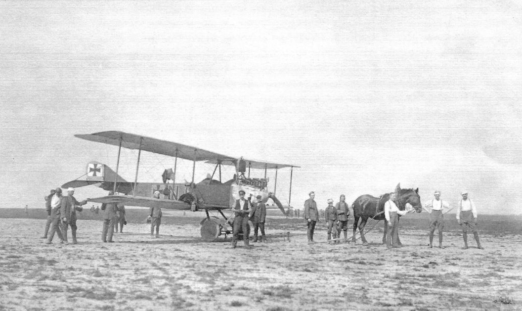
NFW B.I from the NFW flight school. A flat radiator has been mounted over the engine in front of the cockpits. Transportation is being supplied by a horse. (Peter M. Grosz collection, STDB)
NFW B.I N.14 from the NFW flight school. The aircraft has been dismantled for transportation. (Peter M. Grosz collection, STDB)
NFW B.I trainer in flight. (Peter M. Grosz collection, STDB)
NFW B.I
NFW B.I
NFW B.I
NFW E.I
The NFW E.I was built in spring 1916 to the design of Dipl. Ing. Hergt. Intended as a fighter, it was built of wood. The wing was a two-spar, semi-cantilever design with plywood covering built in a single piece,- the pilot's cockpit was between the two spars. Like the well-known Fokker Eindeckers, the NFW E.I had no fixed tail surfaces. However, unlike most Eindecker designs, the NFW E.I used ailerons for roll control rather than the typical wing-warping, made necessary by its much stronger and stiffer wing structure. The 'E' designation was likely a factory, not military, designation.
With only 80 hp the NFW E.I did not have enough performance to be competitive in 1916 and was abandoned in favor of the more powerful E.II.
NFW E.I Specifications
Engine: 80 hp Oberursel U.0
Wing: Span 10.00 m
Wing Area 15.72 m2
General: Length 6.50 m
Empty Weight 428 kg
Loaded Weight 620 kg
Maximum Speed: 156 kmh
Climb: 1,300m 6.0 min.
NFW Experimental Monoplane
The NFW experimental monoplane was a modification of the NFW E.I. Fixed horizontal stabilizers were added and the vertical tail appears to have been slightly modified.
This aircraft may have been the same airframe as the E.I after modification. No further details are known.
Before WWI there were indeed light aircraft NFW E.1 to E.6, but built by another NFW, the Nordwestdeutsche Flugzeugwerke NFW, Heinrich Evers & Co in Bremervorde.
Heinrich Evers had emigrated to the USA, where he worked in the automobile industry, and where he became interested in aviation, witnessing the flights of Glenn Curtiss. In 1909 he returned to Germany, built aeroplanes from 1910, and founded the Nordwestdeutsche Flugzeugwerke, NFW, in 1912. Due to financial problems he closed his firm in 1913, and went back to the USA, where he worked for Benoist. At the outbreak of WWI he returned to Germany, but on the way he was interned in France. He escaped and went to work for Caspar. In 1924 he went back to the USA, working for Fokker, and returned a last time to Germany in 1936, to work for Junkers on the Ju-88.
In all he built six aeroplanes in the period 1910-1913 (plus one un-built project):
E.1: Single sea ter monoplane (1910) with 30 hp Hilz engine.
E.2: Single seater monoplane (1911) with 30 hp Hilz engine. Improved E.1.
E.3: Two seater monoplane with Hilz engine.
E.4: Single seater monoplane (1912) with 40 hp Hilz engine (also with Anzani). Copy of the 1911-12 Schulze Eindecker.
E.5: Single seater monoplane with Hilz engine.
E.6: Two seater Pfeil-Eindecker with 50 hp Gnome.
E.7: Pfeil-Eindecker with Hilz engine. Project only.
http://www.secretprojects.co.uk/forum/index.php/topic,22511.105.html
The NFW E.I at Johannisthal. The Eindecker era was coming to a close when it was built in 1916. (Peter M. Grosz collection, STDB)
The NFW E.I fighter prototype was under-powered for a fighter in 1916 when it was built. (Peter M. Grosz collection, STDB)
The NFW experimental monoplane was a modification of the NFW E.I.
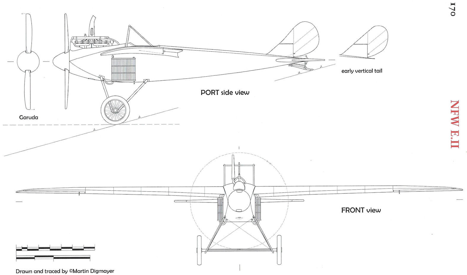
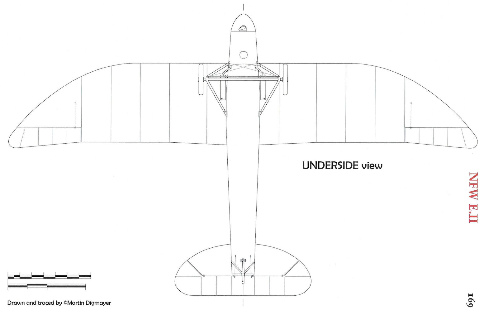
NFW E.II
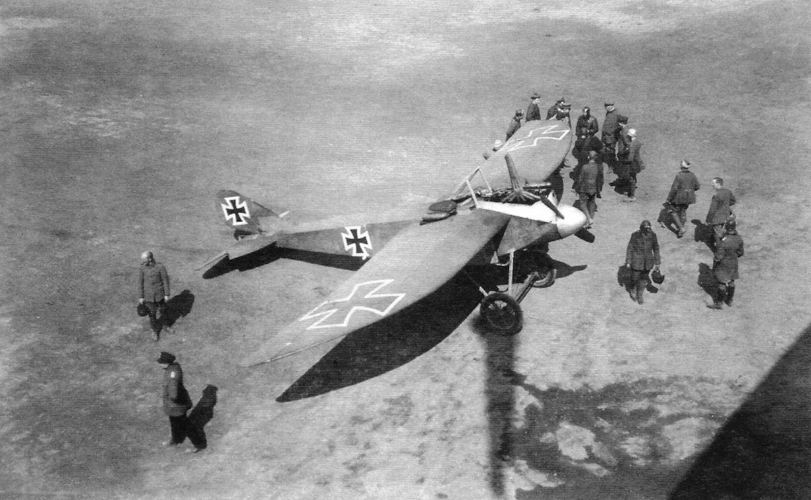
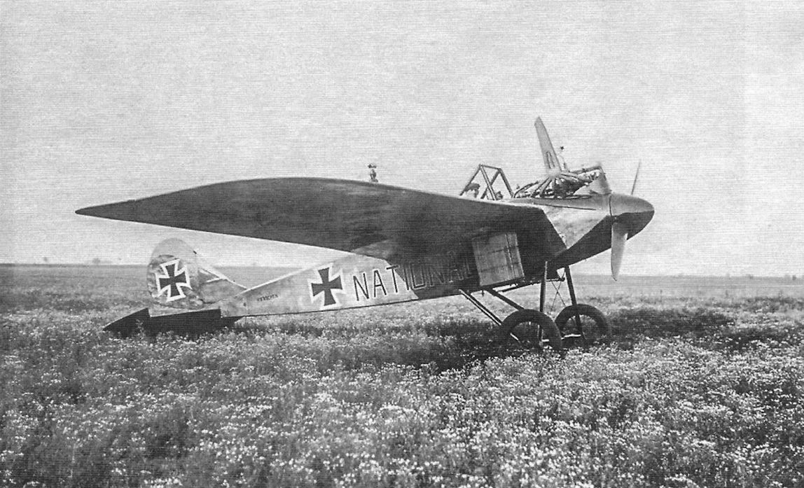
The National Flugzeug-Werke (NFW) at Leipzig was primarily involved in aircraft repair and flight training. However, NFW built a couple of fighter prototypes. The NFW E.I was a typical Eindecker except for its wing, but the NFW E.II was an interesting example of a third-generation German fighter. Built in 1917 to the design of Dipl. Ing. Heinrich, it featured a combination of a first-generation Eindecker configuration with a powerful engine and greatly improved wing design.
In contrast to the Fokker and Pfalz Eindeckers that used wire-braced wings and wing-warping for roll control, the NFW E.II had plywood-covered cantilever wings with minimal wire bracing and was fitted with ailerons for roll control. The two wing spars were continuous through the fuselage for greater strength and the pilot sat between them.
Unlike most Eindecker fighters, the NFW E.II was powered by a water-cooled engine, in this case a 160 hp Mercedes D.III. The more streamlined design and greater power resulted in much improved performance compared to earlier Eindeckers, with maximum speed improved by 30 km/h, making it faster than Albatros fighters, and the climb rate more than doubled despite its greater weight.
Although the NFW E.II displayed good performance, nothing is known about its handling qualities or maneuverability, both critical aspects of a fighter. In any case, for unknown reasons (perhaps bias against monoplanes?) this rare, little-known fighter was limited to a single prototype.
The NFW E.II was the most advanced German monoplane fighter design before the advent of the Fokker monoplane prototypes of 1918 (V17, V23, V25, V27, V28) with their thick, plywood-covered, cantilever wings. Unfortunately, the NFW E.II lacked access to the innovative Fokker wing technology.
NFW E.II Specifications
Engine: 160 hp Mercedes D.III
Wing: Span 12.00 m
Wing Area 17.00 m2
General: Empty Weight 558 kg
Loaded Weight 768 kg
Maximum Speed: 186 kmh
Climb: 2,900 m 6.3 min.
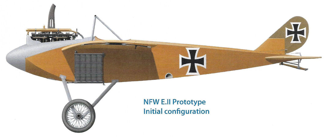
NFW E.II Prototype. Initial configuration
Unlike most E-types that had rotary engines, the NFW E.II had a 160 hp Mercedes D.III, giving it much better performance. This appears to be its initial configuration with smaller rudder and natural metal cowling and spinner. Although a pleasing design with fairly good speed, only one aircraft was built.
The photo clearly shows an enlarged rudder and the cowling and spinner are painted dark (green?).
The NFW hangar at Johannisthal. NFW B.I trainers N.11 and N.12 are visible at left and the prototype NFW E.II is at right without its spinner. (Peter M. Grosz collection, STDB)
NFW E.II

NFW E.II
NFW E.II
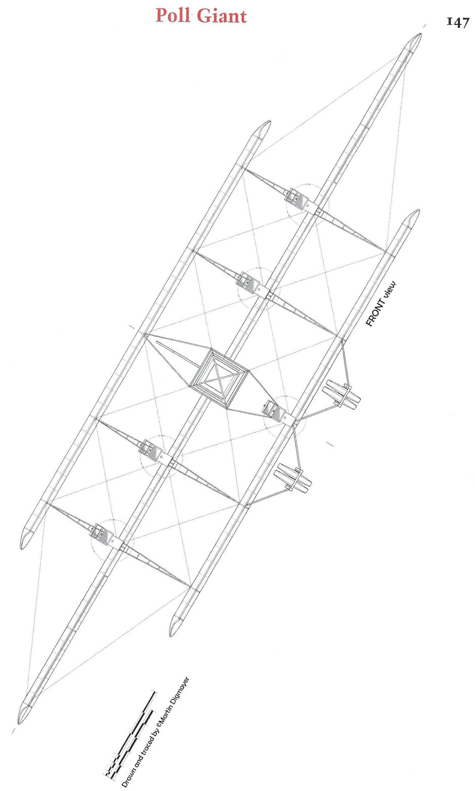
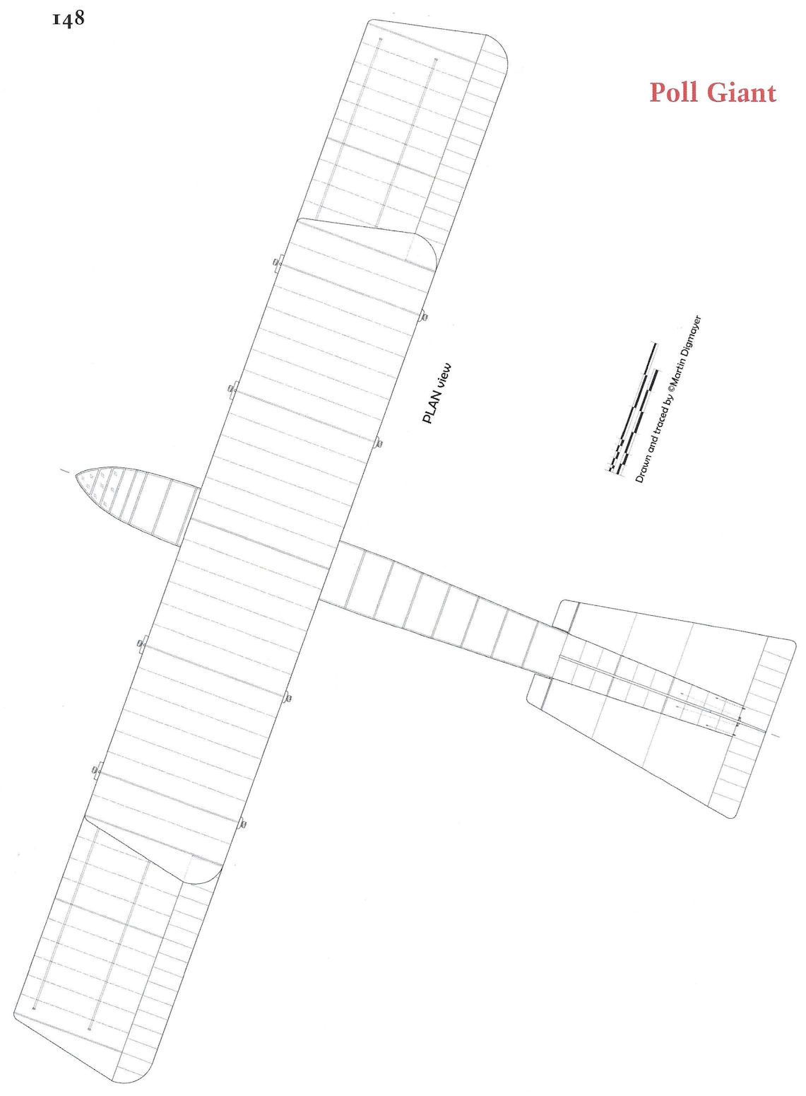
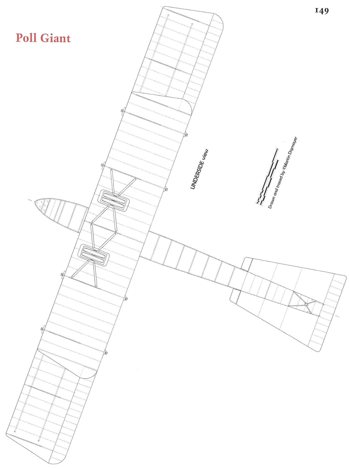
Poll Giant
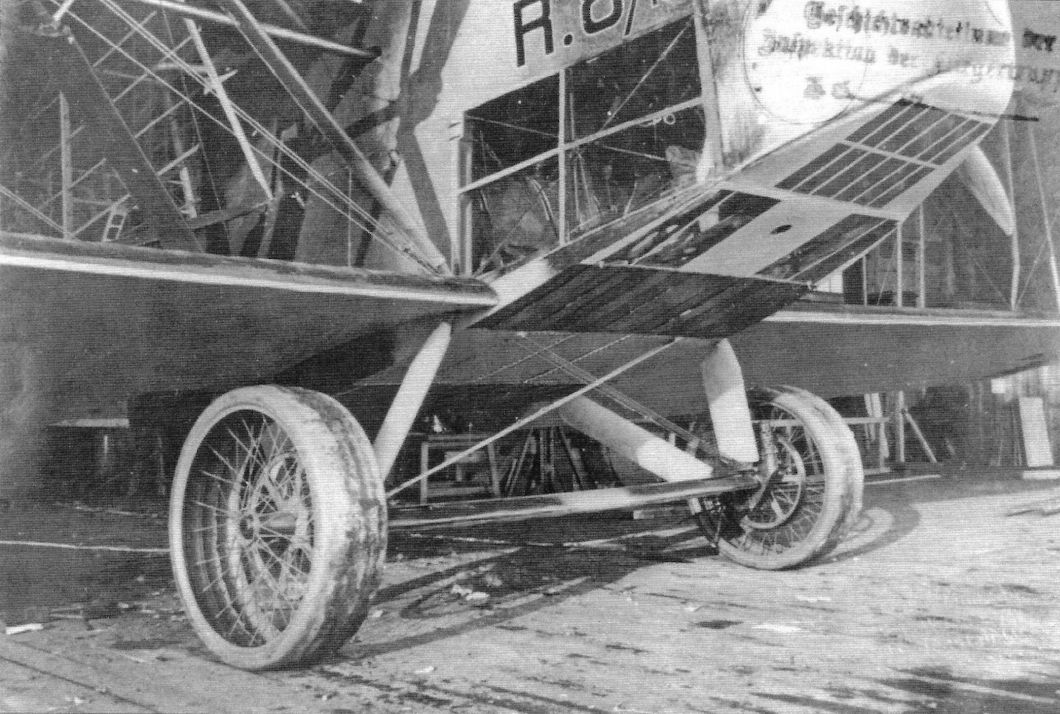
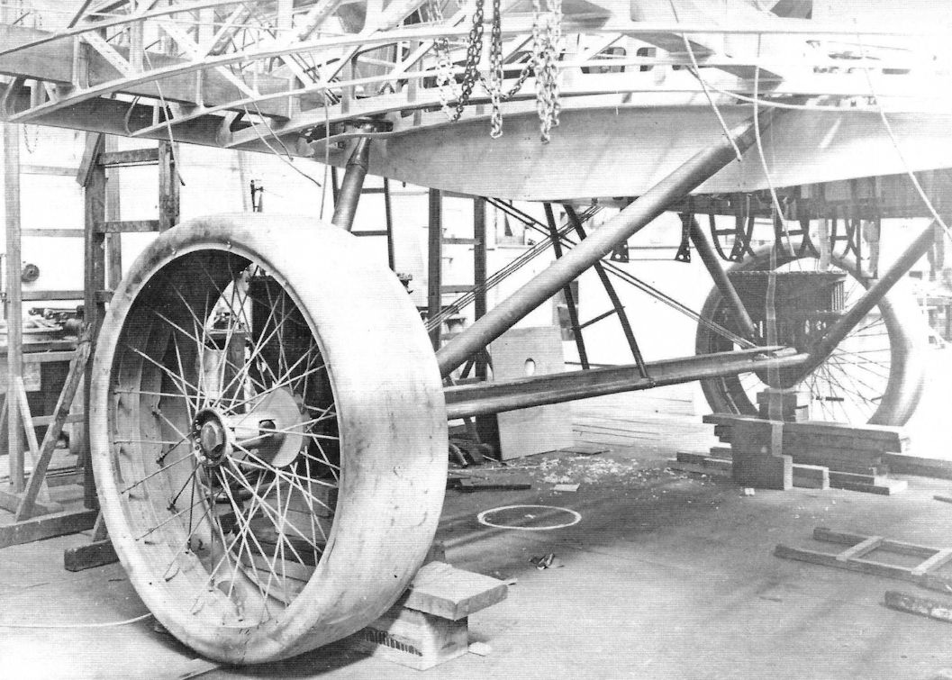
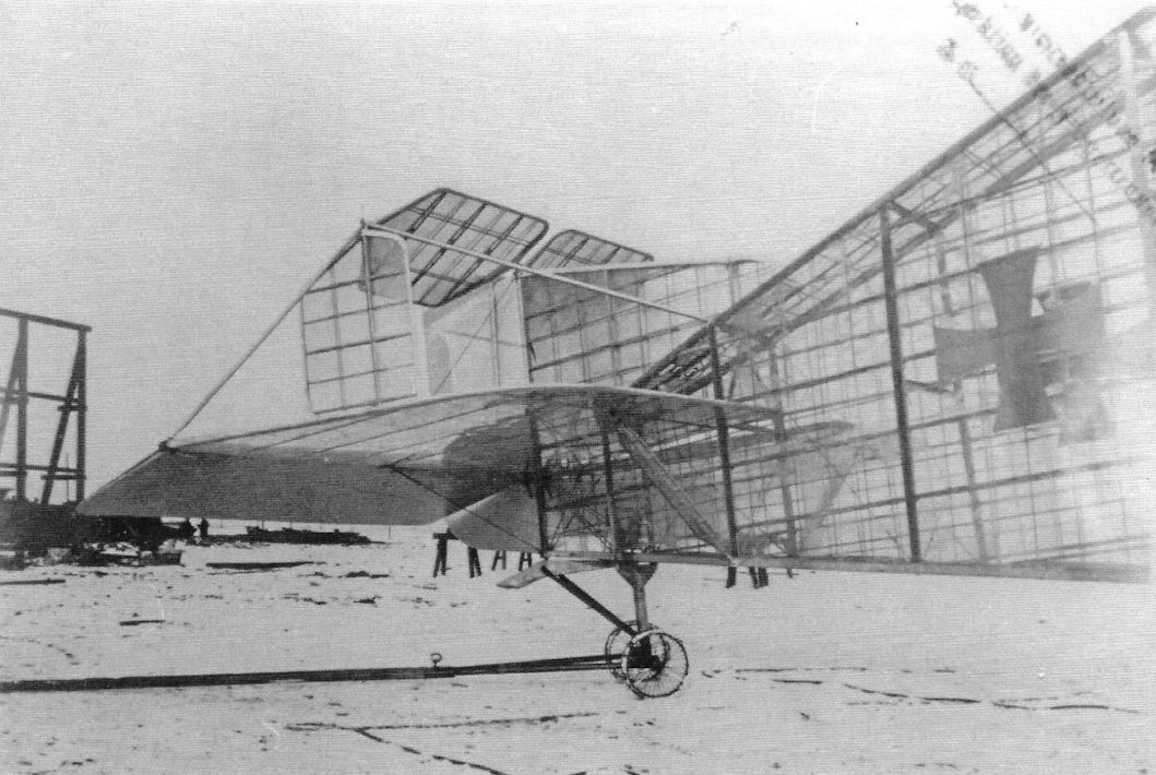
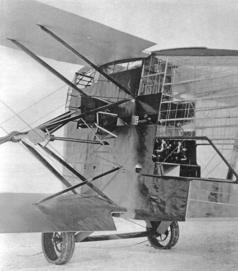
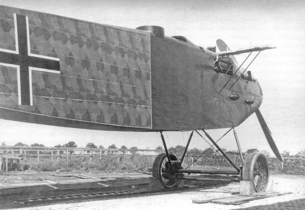
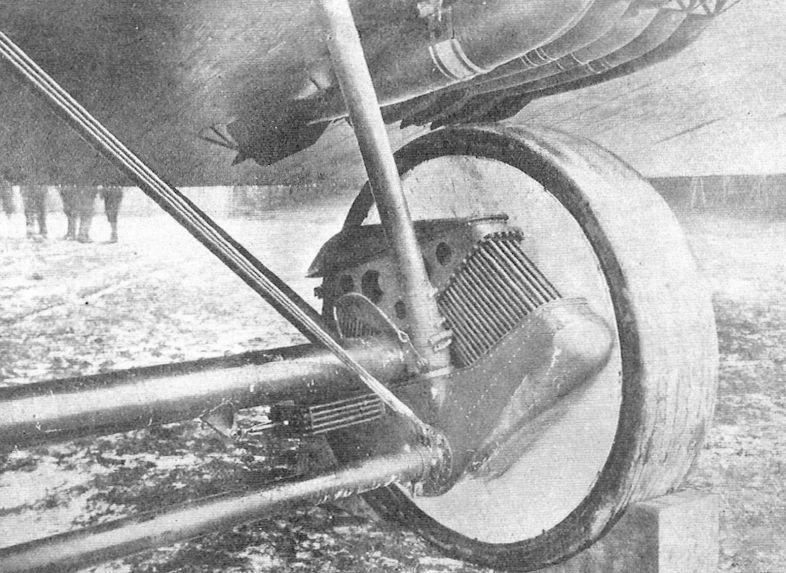
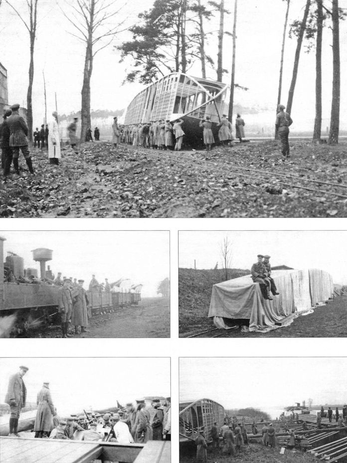
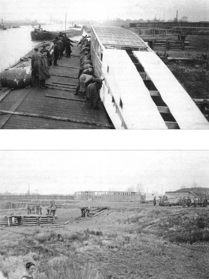
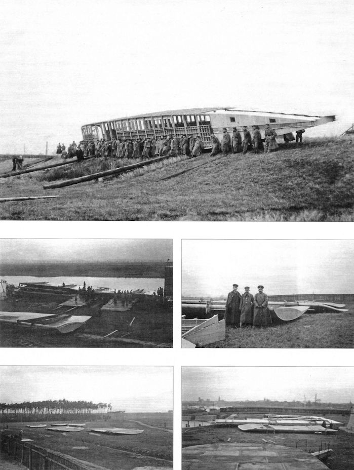
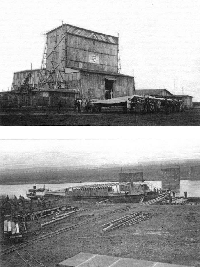
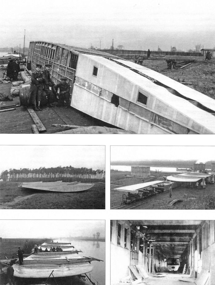
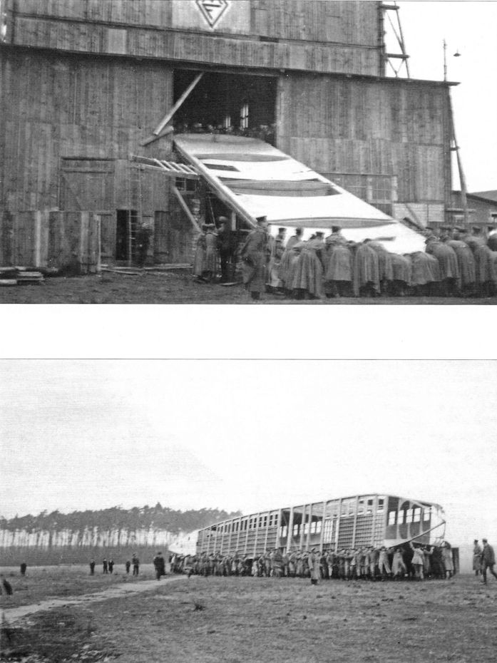
The Poll Giant was a huge, 10-engine triplane design intended to bomb New York. As fantastic as this sounds, this intercontinental bomber was actually being constructed until abandoned after the armistice. One of the 7-foot 9-inch diameter wooden wheels was built and photographed and sections of the fuselage were built and found postwar at the Poll airfield near Cologne. A successful intercontinental bomber was far beyond the technology of 1918; the first aircraft that could actually perform such a mission was the B-36, which first flew in 1946 and reached service in 1948, 30 years after the Poll Giant was designed and construction started. The state of the art required to perform its mission was far beyond the technology of the Poll Giant.
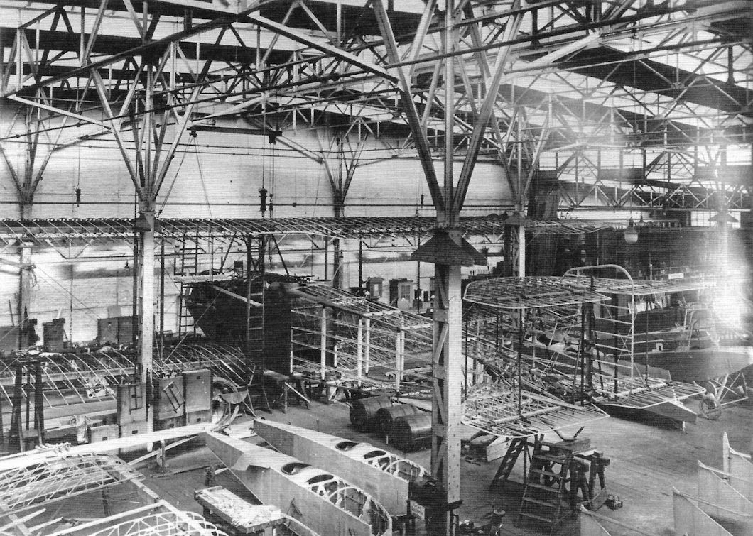
Apparently the Poll Giant was designed to carry enough fuel for an 80-hour flight. Financing was from commercial sources, indicating the original intention was as a passenger transport. Most of the airplane's components were built before the armistice but not all had been assembled. The middle wing had much greater span than the top an bottom wings and their wood structure was covered with 3-ply plywood with a layer of fabric on top. The fuselage was also a wood framework also covered with 3-ply veneer. Members of the IAACC team who inspected the partially-completed prototype postwar thought the wings and fuselage structure were too weak and too heavy.
The type and power of the ten engines are not known.
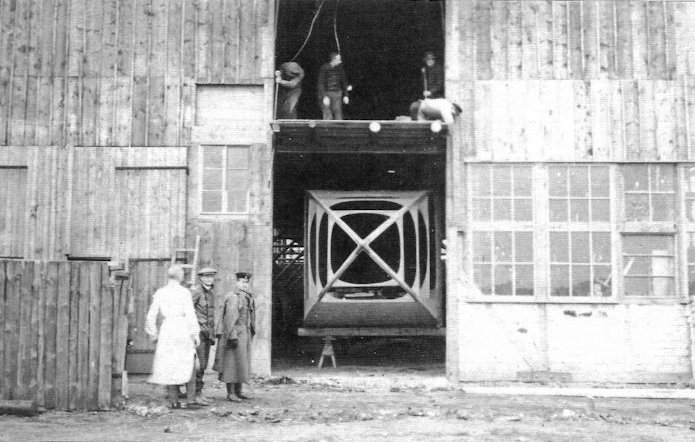
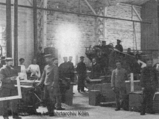
In the fall of 1917 the components built for the Poll Giant had to be moved from Bruning's factory at Kahl to Mannesmann's specially built hangar at Westhoven, about 150 miles (240 km) away. The accompanying photos were taken during this move.
Poll Giant Specifications
Engines: 10 engines, power & type unknown
Wing: Span, middle 50.3 m
Span, Top &. Bottom 31.1 m
Chord 6.7 m
Gap 5.5 m
General: Length 45.7 m
Wheel Diameter 2.4 m
Maximum Speed: 130 km/h
Landing Speed: 90-100 km/h
Duration: 80 hours
The Poll Giant was a huge, 10-engine triplane design intended to bomb New York. As fantastic as this sounds, this intercontinental bomber was actually being constructed until abandoned after the armistice. One of the 7-foot 9-inch diameter wooden wheels was built and photographed and sections of the fuselage were built and found postwar at the Poll airfield near Cologne. A successful intercontinental bomber was far beyond the technology of 1918; the first aircraft that could actually perform such a mission was the B-36, which first flew in 1946 and reached service in 1948, 30 years after the Poll Giant was designed and construction started. The state of the art required to perform its mission was far beyond the technology of the Poll Giant.
Apparently the Poll Giant was designed to carry enough fuel for an 80-hour flight. Financing was from commercial sources, indicating the original intention was as a passenger transport. Most of the airplane's components were built before the armistice but not all had been assembled. The middle wing had much greater span than the top an bottom wings and their wood structure was covered with 3-ply plywood with a layer of fabric on top. The fuselage was also a wood framework also covered with 3-ply veneer. Members of the IAACC team who inspected the partially-completed prototype postwar thought the wings and fuselage structure were too weak and too heavy.
The type and power of the ten engines are not known.
In the fall of 1917 the components built for the Poll Giant had to be moved from Bruning's factory at Kahl to Mannesmann's specially built hangar at Westhoven, about 150 miles (240 km) away. The accompanying photos were taken during this move.
Poll Giant Specifications
Engines: 10 engines, power & type unknown
Wing: Span, middle 50.3 m
Span, Top &. Bottom 31.1 m
Chord 6.7 m
Gap 5.5 m
General: Length 45.7 m
Wheel Diameter 2.4 m
Maximum Speed: 130 km/h
Landing Speed: 90-100 km/h
Duration: 80 hours
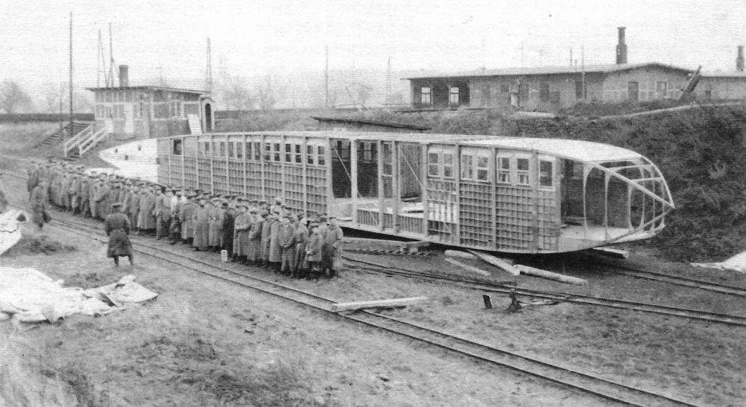
The Poll Giant fuselage and other components were moved from Bruning's factory at Kahl to Mannesmann's specially built hangar at Westhoven, about 150 miles (240 km) away, in the fall of 1917. Although it reached its new location, the aircraft was never finished.
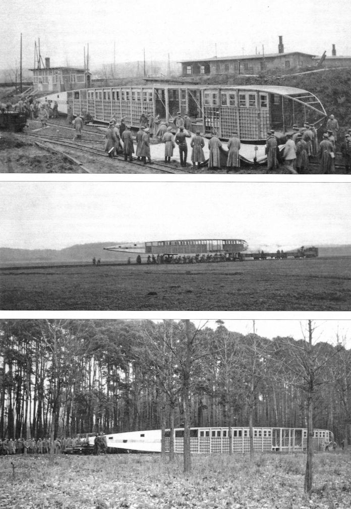
Moving the Poll Giant Components, Fall 1917 (Peter M. Grosz collection, STDB)
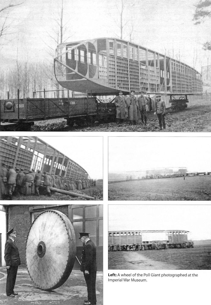
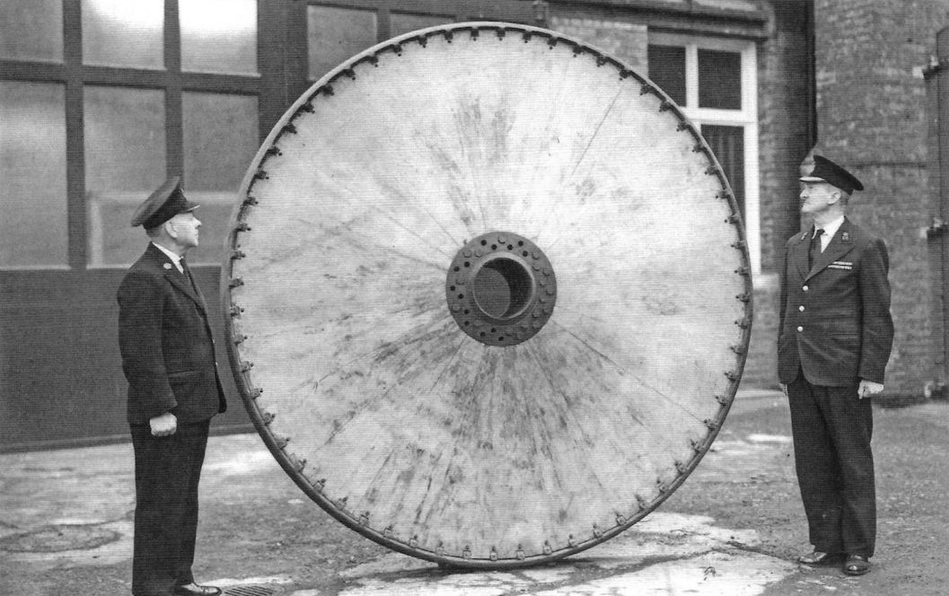
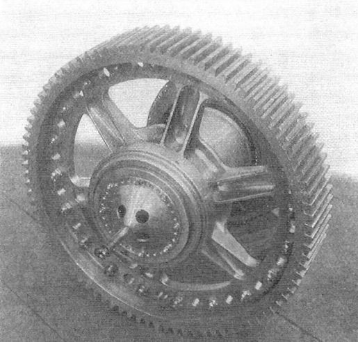
One of the huge 2.4 m (7 foot, 9 inch) diameter all-wood wheels made for the Poll Giant. The photos were taken at the Imperial War Museum where the wheel was once on display and is now in storage.The Poll Giant was a huge triplane bomber with ten engines that was being constructed in 1918, but was not completed by the armistice. Work stopped at war's end and the type was never completed nor flown.
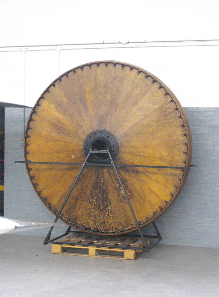
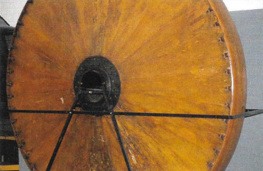
The 2.4 m (7 foot 9 inch) wood wheel of the Poll Giant, the surviving artifact from this project now stored in the Imperial War Museum.
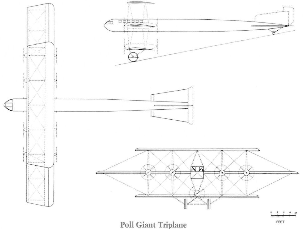
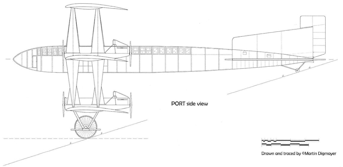
Poll Giant. The Poll Giant was never completed so its exact appearance is not known. Marty has drawn it with 300 hp Maybach engines and a Forsmann-style under-carriage, although these details are unknown. The length in these drawings is substantially less than shown before. Typical contemporary aircraft had a span to length ratio of 3:2 rather than 1:1 and the illustrator thought that the design length may have been 105 feet instead of 150 feet as noted before, perhaps due to a transcription error. In any case, 105 feet long seems more realistic and it was drawn that way. Compare with an earlier drawing on page 64. Your estimate by vary!
Poll Giant
Poll Giant
Poll Giant
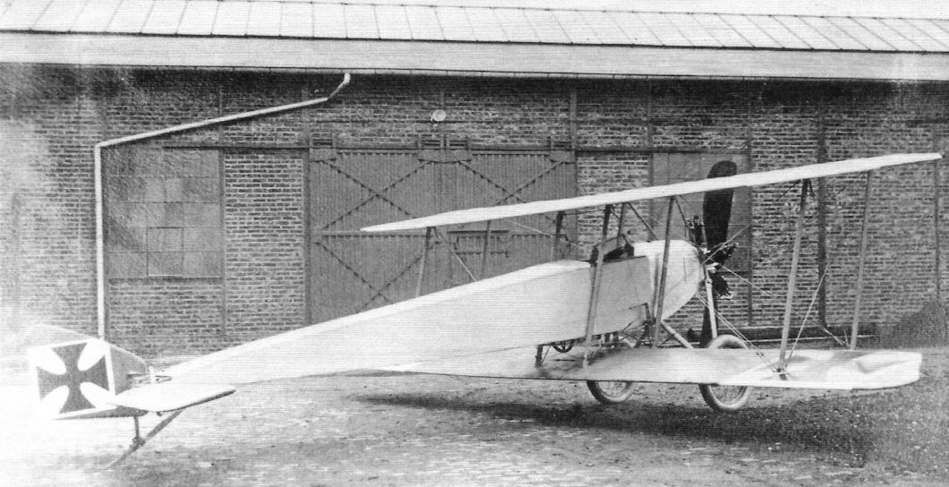
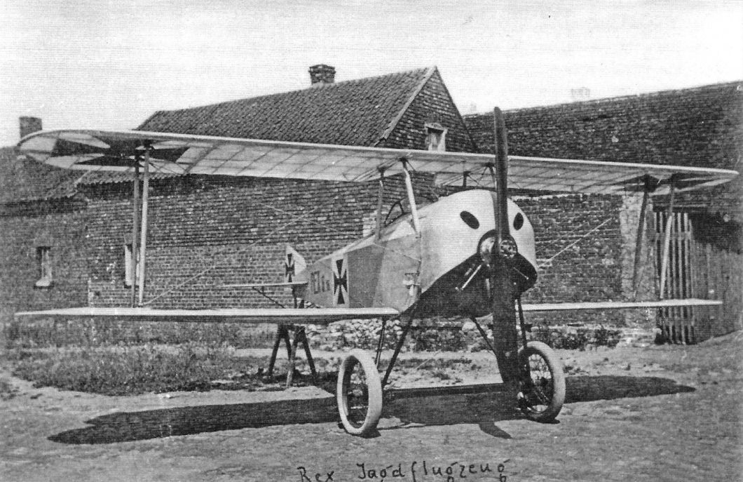
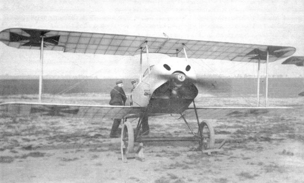
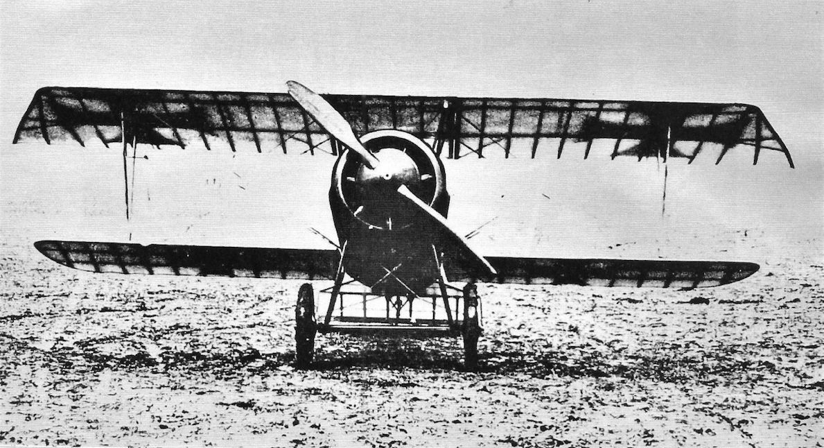
The primitive Rex single-seat biplane with odd landing gear design. (Peter M. Grosz collection, STDB)
Rex
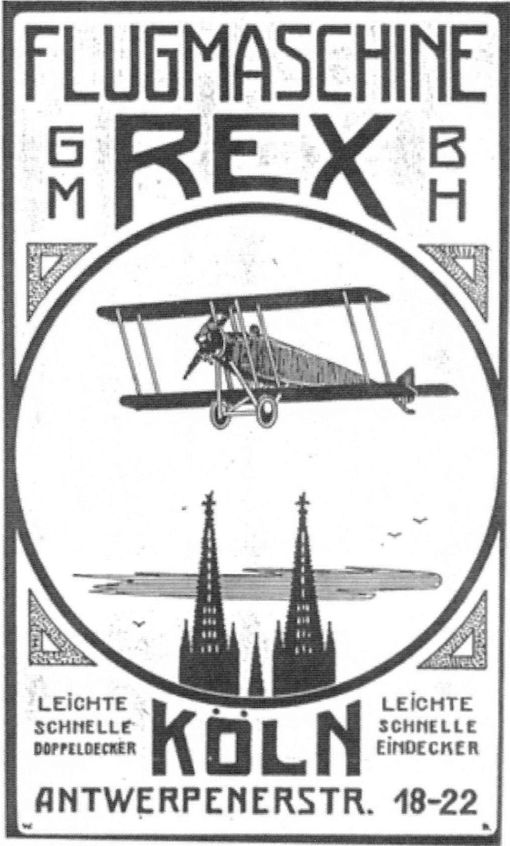
The Flugmaschinen Rex-Gesellschaft mbH company was established on 14 December 1914 by Walter Gutbire. The company intended to build a Morane-type monoplane and a biplane, similar to the Bristol Scout, but nothing came of this. The first trials of a small biplane were held on the Manne-Herten airfield which, due to rising costs, were curtailed. The same fate befell the design of a rotary engine that was proposed to power the biplane. During these trials a repair facility for military aircraft was established. The company then concerned itself with the repair of aircraft, but also experimented in 1917, by building a fighter the "D17" that was described as an almost exact copy of the Albatros and was never accepted.
The Flugmaschinen Rex-Gesellschaft mbH company was established on 14 December 1914 by Walter Gutbire. The company intended to build a Morane-type monoplane and a biplane, similar to the Bristol Scout, but nothing came of this. The first trials of a small biplane were held on the Manne-Herten airfield which, due to rising costs, were curtailed. The same fate befell the design of a rotary engine that was proposed to power the biplane. During these trials a repair facility for military aircraft was established. The company then concerned itself with the repair of aircraft, but also experimented in 1917, by building a fighter the "D17" that was described as an almost exact copy of the Albatros and was never accepted.
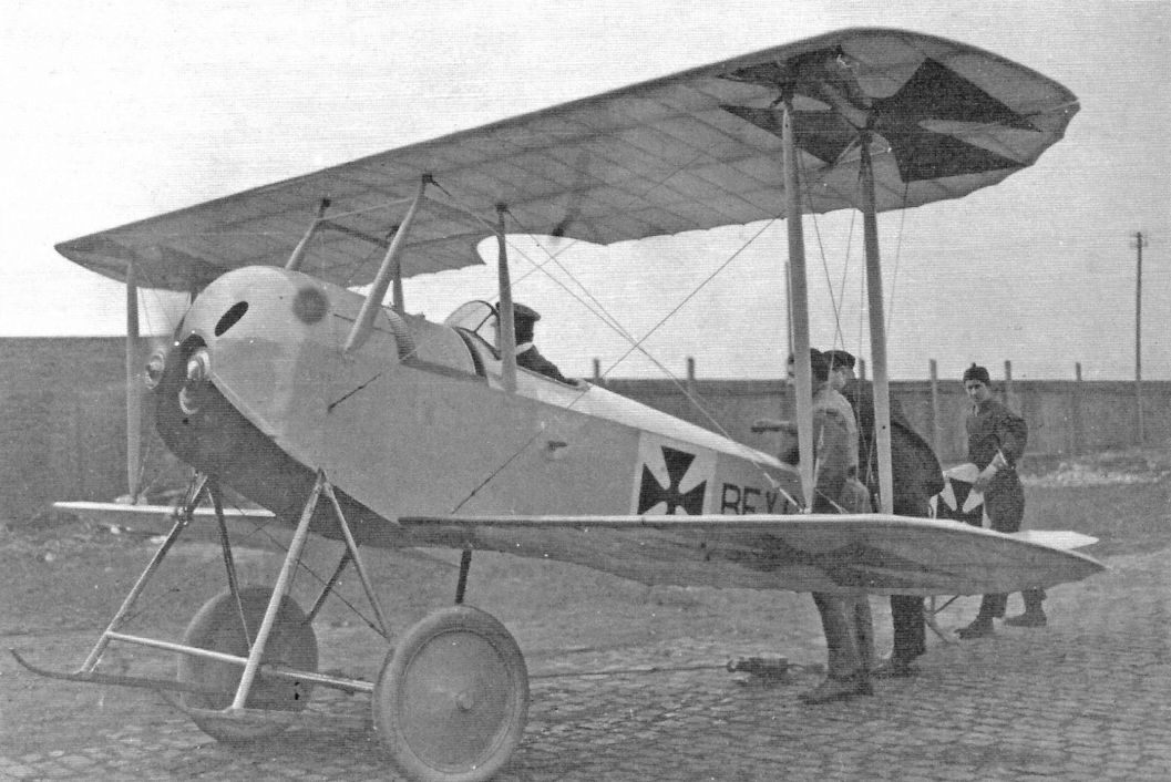
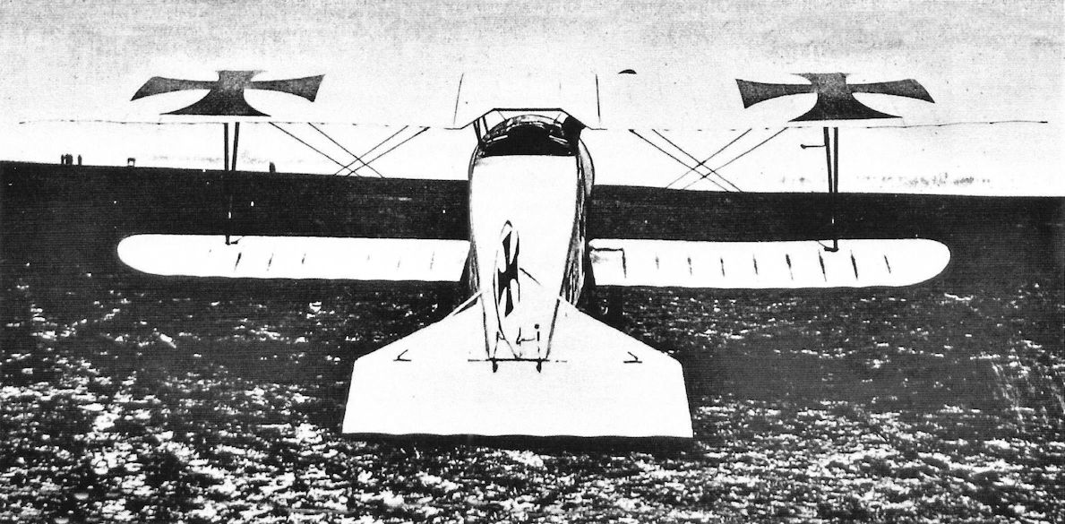
The unarmed Rex single-seat fighter prototype was powered by an 80 hp Oberursel U.0 rotary. Initially the landing gear was fitted with nose-over skids as shown. (Peter M. Grosz collection, STDB)
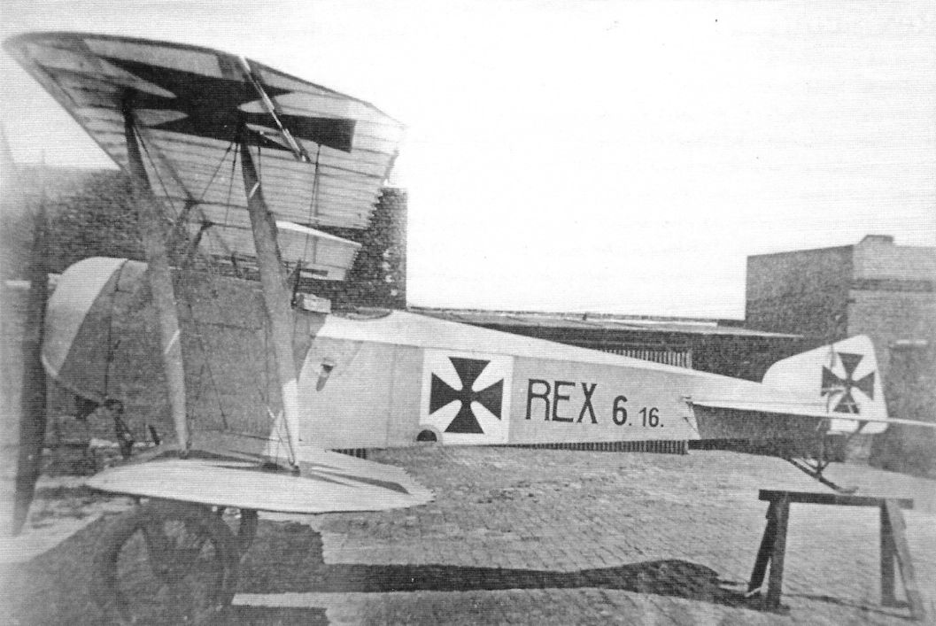
The Rex single-seat fighter prototype was a small, single-bay biplane that had an unusually shaped fin and rudder. It remained a single prototype. (Peter M. Grosz collection, STDB)
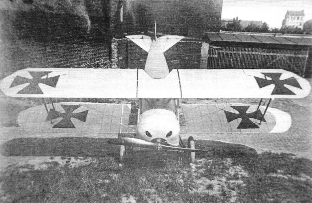
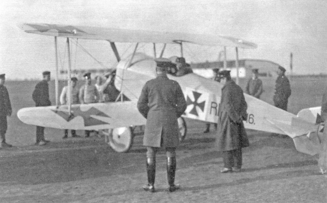
The Rex single-seat fighter prototype was numbered 6.16. and carried national insignia on both sides of the wings plus fuselage and rudder. It is shown here after the nose-over skids were removed. (Peter M. Grosz collection, STDB)
Rex
The Flugmaschinen Rex-Gesellschaft mbH company was established on 14 December 1914 by Walter Gutbire. The company intended to build a Morane-type monoplane and a biplane, similar to the Bristol Scout, but nothing came of this. The first trials of a small biplane were held on the Manne-Herten airfield which, due to rising costs, were curtailed. The same fate befell the design of a rotary engine that was proposed to power the biplane. During these trials a repair facility for military aircraft was established. The company then concerned itself with the repair of aircraft, but also experimented in 1917, by building a fighter the "D17" that was described as an almost exact copy of the Albatros and was never accepted.
The Flugmaschinen Rex-Gesellschaft mbH company was established on 14 December 1914 by Walter Gutbire. The company intended to build a Morane-type monoplane and a biplane, similar to the Bristol Scout, but nothing came of this. The first trials of a small biplane were held on the Manne-Herten airfield which, due to rising costs, were curtailed. The same fate befell the design of a rotary engine that was proposed to power the biplane. During these trials a repair facility for military aircraft was established. The company then concerned itself with the repair of aircraft, but also experimented in 1917, by building a fighter the "D17" that was described as an almost exact copy of the Albatros and was never accepted.
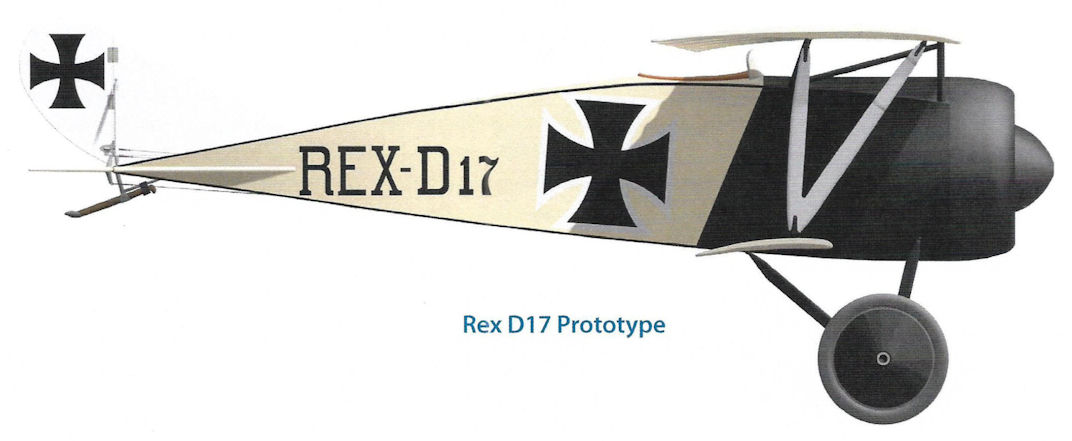
Rex D17 Prototype
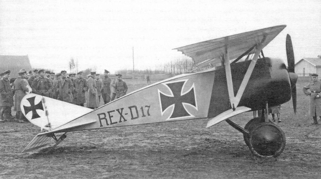
In 1917 Rex built another unarmed single-seat fighter prototype labelled the Rex D17. It was a clean design inspired by the Nieuport with single-spar lower wing. It was powered by a 100 hp rotary that was cleanly cowled and fitted with a spinner. Only the one aircraft was built. (Peter M. Grosz collection, STDB)
The Rex D17 was supposedly sponsored by the German fighter "ace", Leutnant Werner Voss.
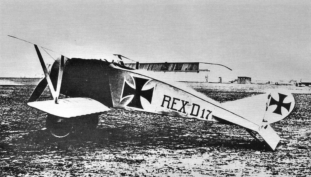
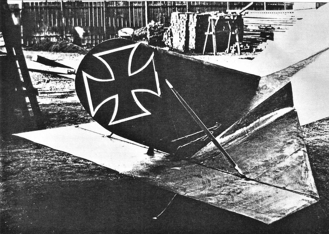
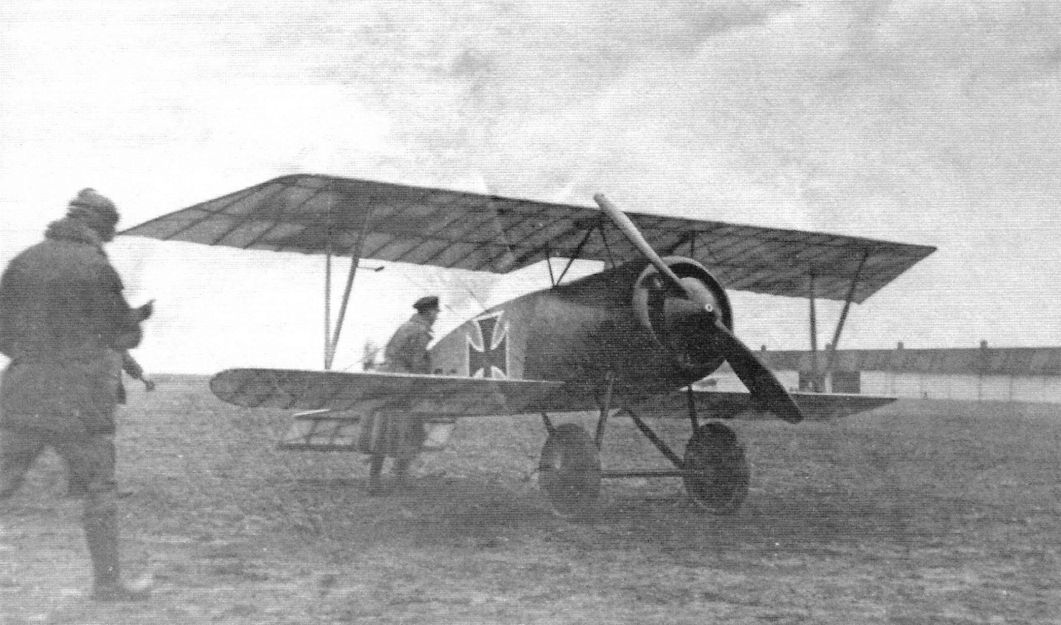
More views of the Rex D17. The close-up of the tail shows the severe lines of the horizontal tail.
More views of the Rex D17 fighter prototype labelled the Rex D17. Unfortunately, the wing cellule followed the Nieuport sesquiplane design with single-spar lower wing that caused so many structural problems with the original Nieuports and the Albatros D.III and especially D.V/Va that also used a single-spar lower wing. Use of a 100 hp rotary limited its speed and climb and made it non-competitive for 1917 despite its careful streamlining. Lacking any design innovations boosting performance, it had no chance of production.
Rex D17
Rex D17
Schneider
Before the war Franz Schneider had been working with M Edouard Nieuport. He then moved to L.V.G. where he was an engineer when the war broke out. On 22 January 1917, he and his wife, Lucie Schneider, founded his own company, Franz Schneider Flugmachine Werke GmbH, to repair aircraft. The company took over the facilities of the German Railway and Dining Car Co. (in liquidation). From June 1917 to the end of March 1918, about 170 repaired aircraft were delivered - Albatros, L.V.G., and D.F.W types - and it was still in process when the Armistice was declared. The IAACC inventoried 12 aircraft and spare parts when it inspected his facility. There is no record of his single-seat fighter that was built in 1918 in the IAACC Report.
Before the war Franz Schneider had been working with M Edouard Nieuport. He then moved to L.V.G. where he was an engineer when the war broke out. On 22 January 1917, he and his wife, Lucie Schneider, founded his own company, Franz Schneider Flugmachine Werke GmbH, to repair aircraft. The company took over the facilities of the German Railway and Dining Car Co. (in liquidation). From June 1917 to the end of March 1918, about 170 repaired aircraft were delivered - Albatros, L.V.G., and D.F.W types - and it was still in process when the Armistice was declared. The IAACC inventoried 12 aircraft and spare parts when it inspected his facility. There is no record of his single-seat fighter that was built in 1918 in the IAACC Report.
Developed by Franz Schneider in 1918. This single seat fighter came too late.
Variable wing incidence was an innovative feature of the single Schneider fighter.
Variable wing incidence was an innovative feature of the single Schneider fighter.
Schutte-Lanz
Registered on 1 June 1909, in Mannheim to construct airships, Luftfahrzeugbau Schutte-Lanz constructed aircraft under license from Ago, LVG, and Staaken during the war. Aircraft production was estimated as a minimum total of 569 of the types shown in the table below.
The IAACC reported the following aeronautical materials found in the factory: 304 aircraft (including 266 LVG biplanes without engines), and 17 engines.
Wilhelm Hillman is usually credited as the designer of the Schutte-Lanz D.I, a copy of the Sopwith Tabloid that appeared in 1915. Research by the late P.M. Grosz indicates that Hillman was the chief engineer, while Stein was the designer. There is a distinction in German and often “der Konstrukteur” is not the chief engineer. (Letter: P.M.G. to J.M.B. 13.08.1989. RAF Museum JM Bruce Collection Box 44.)
Schutte-Lanz License Production
Type Motor hp No. Notes
B.II 100-120 200 School machines
LVG B.III 100-120 300 The LVG B.III was designed as a trainer.
AGO C.IV 200 Benz 66 Production stopped early due to problems with the design.
Staaken R.XIV 5 x 260 Maybach 3 Two (2) completed in 1919.
Source: Rapport Technique, Commission Interalliee de Controle Aeronautique en Allemagne.
Schutte-Lanz C.I
The first original Schutte-Lanz airplane design was the C.I pusher built in 1915. Power was a 160 hp Mercedes D.III. The gunner in the front cockpit was provided with a flexible Parabellum machine gun.
The only pusher two-seaters placed in production were the Otto C.I and Ago C.I and no production of the Schutte-Lanz C.I was undertaken.
Schutte-Lanz C.I prototype. Power was a 160 hp Mercedes D.III. The observer sat in front with a flexible machine gun and had an excellent view forward and upward. However, German authorities greatly preferred the tractor configuration and few German pusher designs were made. The radiator was installed in the nose of the nacelle. (Peter M. Grosz collection, STDB)

Schutte-Lanz C.I prototype built in 1915. Only the one aircraft was built. It was one of the few pusher designs built in Germany. (Peter M. Grosz collection, STDB)
Schutte-Lanz D.I & D.II
In the summer of 1915 Schutte-Lanz produced a single prototype of a single-seat scout, the D.I. Designed by Dip. Ing. Wilhelm Hillmann and Walter Stein, the biplane that emerged was obviously influenced by the British Sopwith Tabloid. Powered by a seven-cylinder 80-hp Oberursel rotary engine, the machine was of conventional wooden construction with fabric covering and ply cockpit panels, and aluminium engine cowling. Wing warping was adopted for lateral control. It was unarmed. The aircraft underwent proof testing in February 1916. The pilot's field of vision was poor and Idflieg considered it unsuitable as a fighter compared with contemporary Eindeckers. A revised version with a 100-hp Mercedes six-cylinder in-line engine was proposed as the D.II, but never flew.
In the summer of 1915 Schutte-Lanz produced a single prototype of a single-seat scout, the D.I. Designed by Dip. Ing. Wilhelm Hillmann and Walter Stein, the biplane that emerged was obviously influenced by the British Sopwith Tabloid. Powered by a seven-cylinder 80-hp Oberursel rotary engine, the machine was of conventional wooden construction with fabric covering and ply cockpit panels, and aluminium engine cowling. Wing warping was adopted for lateral control. It was unarmed. The aircraft underwent proof testing in February 1916. The pilot's field of vision was poor and Idflieg considered it unsuitable as a fighter compared with contemporary Eindeckers. A revised version with a 100-hp Mercedes six-cylinder in-line engine was proposed as the D.II, but never flew.
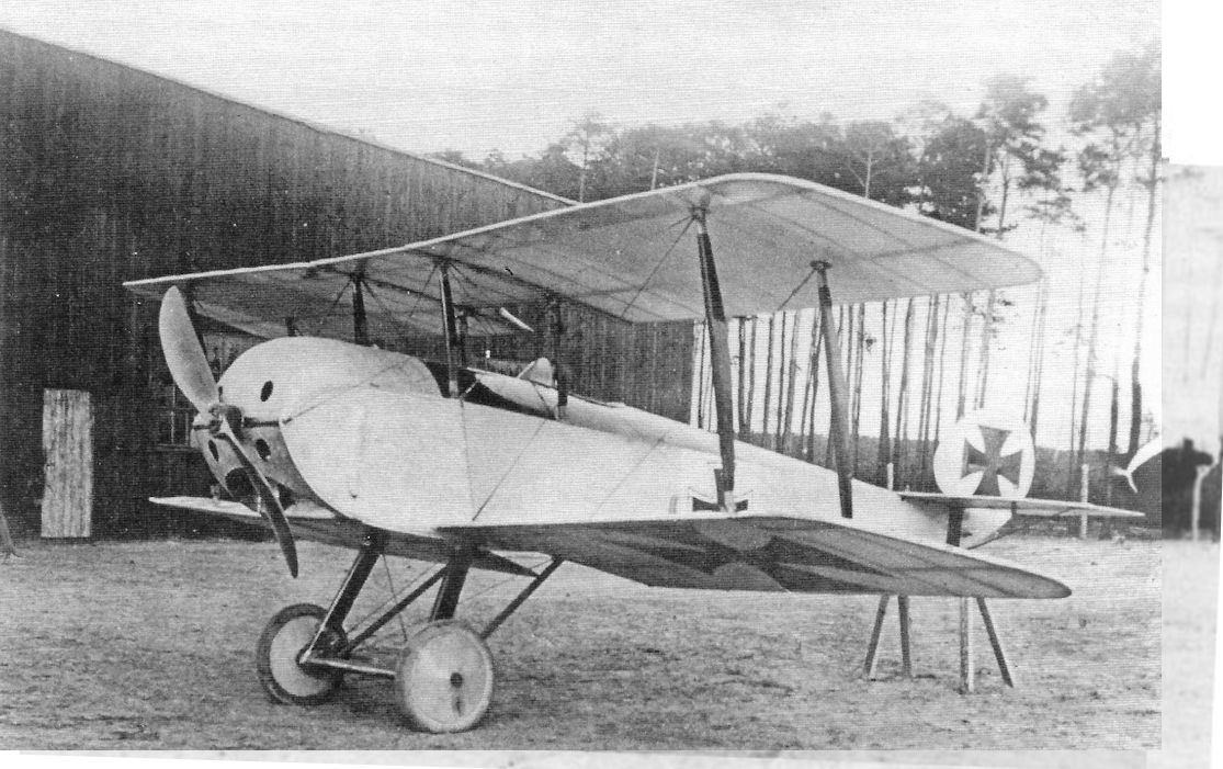
The Schutte-Lanz D.I was built in 1915. Powered by a 80 hp Oberursel (Gnome copy) rotary, the aircraft appears to have been copied from the Sopwith Tabloid although no fixed fin was mounted. As far as is known, only one was built.
Built in 1915, the Schutte-Lanz D I was the first fighter biplane tested in Germany.
Built in 1915, the Schutte-Lanz D I was the first fighter biplane tested in Germany.
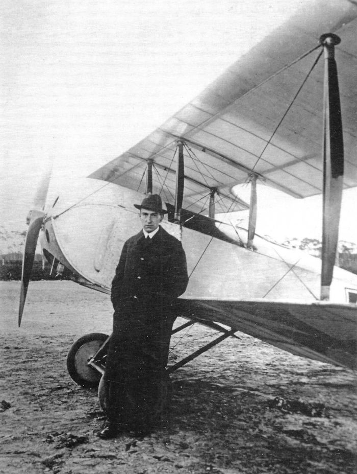
One of the designers of the D.I, Walter Stein, poses with his creation, the Schutte-Lanz D.I.
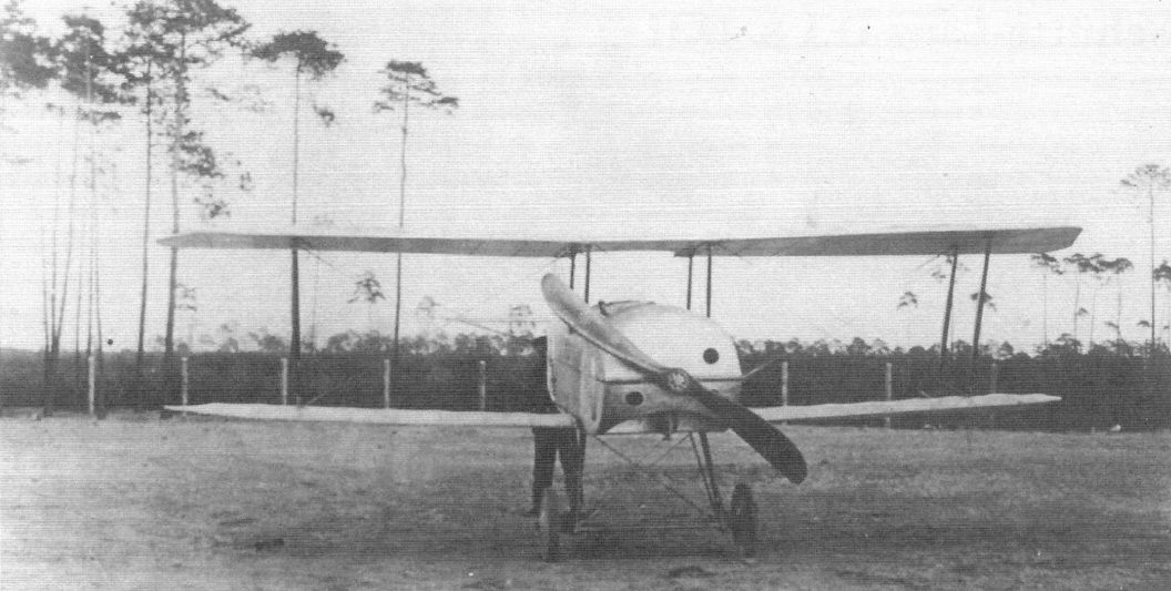
The Schutte-Lanz D.I was a small, modestly-powered aircraft with insufficient performance to be a fighter.
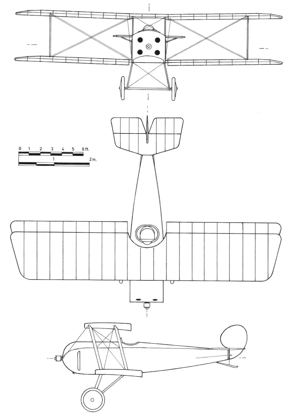
Schutte-Lanz D.I
Schutte-Lanz G.I
Schutte-Lanz is mainly known for building airships, but also built a series of airplane prototypes, none of which reached production. One bomber, the Schutte-Lanz G.I, was built and several others were designed but not built, although the Schutte-Lanz G.V was built by LVG as the LVG G.III.
The Schutte-Lanz G.I was designed and built to the original Kampfflugzeug specification of 1914; it was originally assigned to the "K" category but became the G.I when the G-category replaced it. The fuselage had a five-sided cross section covered with plywood. Two 160 hp Mercedes D.III engines were fitted in a pusher configuration, common to most German two-engine aircraft of the time. As shown in the photo, the propellers were fitted to long extension shafts to clear the wing.
The gunner had a single flexible machine gun in the front cockpit. The configuration did not look balanced; a small rudder without fixed fin was fitted but the horizontal stabilizers were nearly half the length of the fuselage. The G.I was too slow to intercept hostile aircraft and the propeller extension shafts and their supports were heavy and created excessive drag; only one aircraft was completed.
Schutte-Lanz G.I Specifications
Engines: 2 x 160 hp Mercedes D.III
Wing: Span 22.0 m
Area 100.0 m2
General: Length 12.0 m
Height 4.2 m
Empty Weight 1,850 kg
Loaded Weight 3,100 kg
Maximum Speed: 125 km/h
Duration: 6 hours
Armament: 1 flexible MG
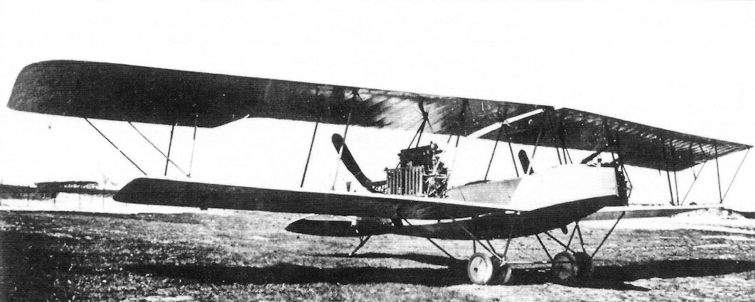
Designed as a battle plane, only one Schutte-Lanz G.I was built.
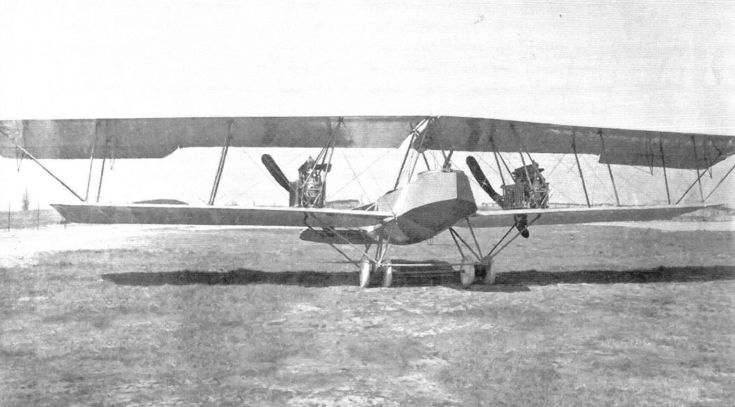
Designed as a Kampfflugzeuge, only one Schutte-Lanz G.I was built. The gunner occupied the front cockpit and had a single flexible machine gun. The fuselage possessed an unusual cross section and heavy supports carried the propeller drive shafts aft so the propellers cleared the wing trailing edge.
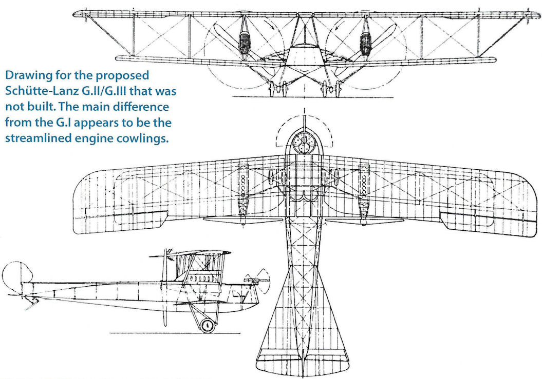
Drawing for proposed Schutte-Lanz G.II/G.III that was not built. The main difference from the G.I appears to be the streamlined engine cowlings.
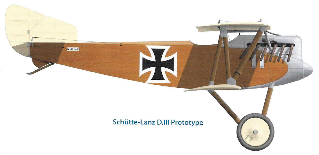
Schutte-Lanz D.III Prototype
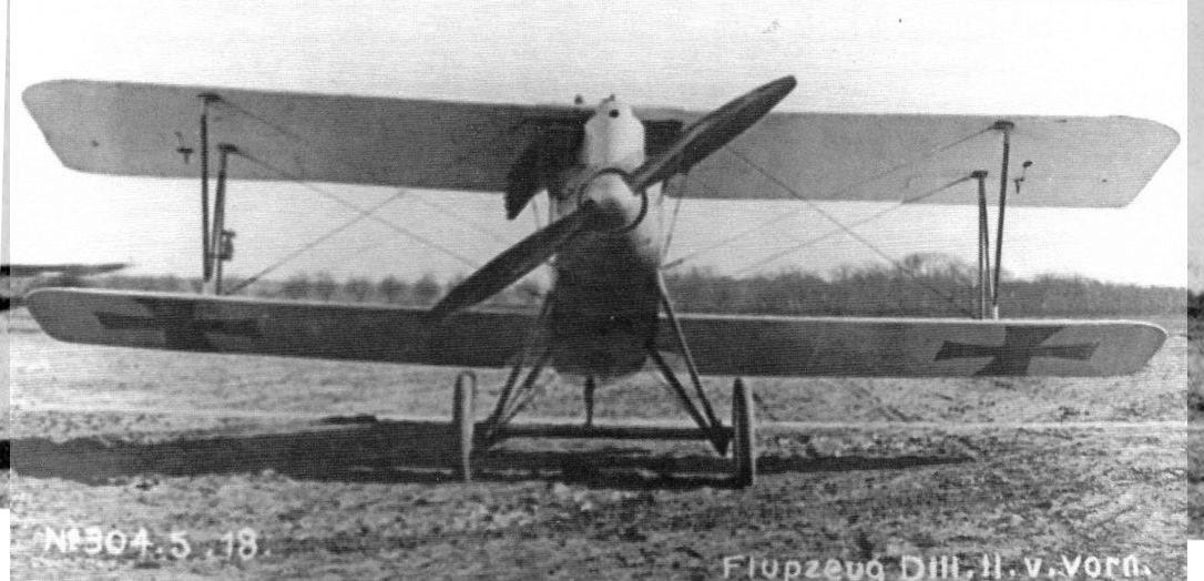
Front view of the Schutte-Lanz D.III fighter prototype powered by the 160 hp Mercedes D.III engine. A neat, conventional design, it offered no advantages over fighters already at the front.
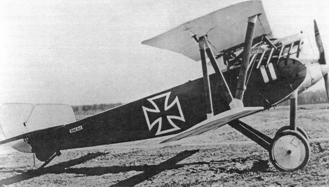
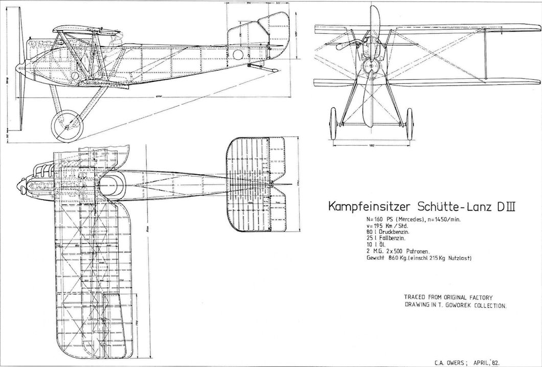
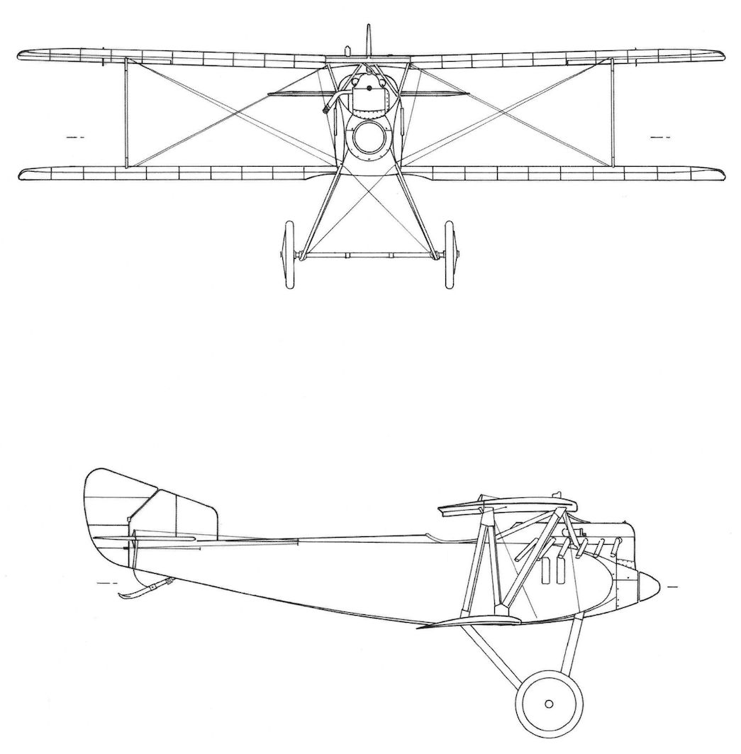
Schutte-Lanz D.III
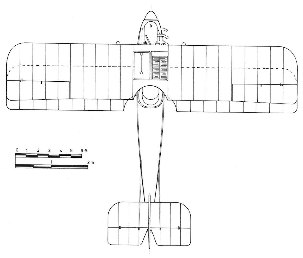
Schutte-Lanz D.III
Schutte-Lanz D.IV
The D.IV was built in parallel with the D.III but the pair had no commonality. No photographs of the completed aircraft are known to exist. Flown in late 1917, the D.IV was inferior to the D.III in performance and was withdrawn from the fighter competition. A further prototype, the D.IVa had a frontal radiator, a revised undercarriage, and shallower fuselage.
Schutte-Lanz D.VII
Schutte-Lanz returned to the Second Fighter Competition with two designs, the Dr.I triplane development of the D.III, the last triplane submitted to a competition, and the D.VII powered by a 180 hp Mercedes D.IIIau. Both types were conventional designs of average performance and neither was selected for production or further development.
Schutte-Lanz Fighter Specifications
D.III D.IV D.VI D.VII
Engine 160 hp Mercedes D.III 195 hp Benz B.IIIbo V-8 160 hp Mercedes D.III 180 hp Mercedes D.IIIau
Span, m 8.0 9.0 10.8 9.0
Chord, upper, m 1.5 1.5 1.6 1.5
Chord, lower, m 1.2 1.2 1.3 1.2
Wing area, m2 20.0 23.3 23.7 24.3
Length, m 6.5 5.8 6.65 6.0
Height, m 3.1 2.963 2.64 3.1
Wt, empty, kg 645 710 800 630
Wt, loaded, kg 860 900 980 810
Max. speed, kmh 195 180
Climb, 1000 m 3.0 min 2.8 min
Climb, 2000 m 5.8 min
Climb, 3000 m 9.7 min
Climb, 4000 m 14.8 min
Climb, 5000 m 31.9 min 14 min 21.3 min
Climb, 6000 m 29.6 min
Climb, 7000 m 29.6 min
Climb, 8000 m 45.5 min
Ceiling, m 8000
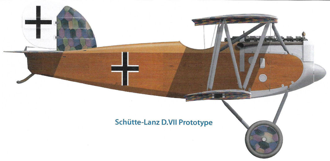
Schutte-Lanz D.VII Prototype

Schutte-Lanz D.IV (without engine) (1917)
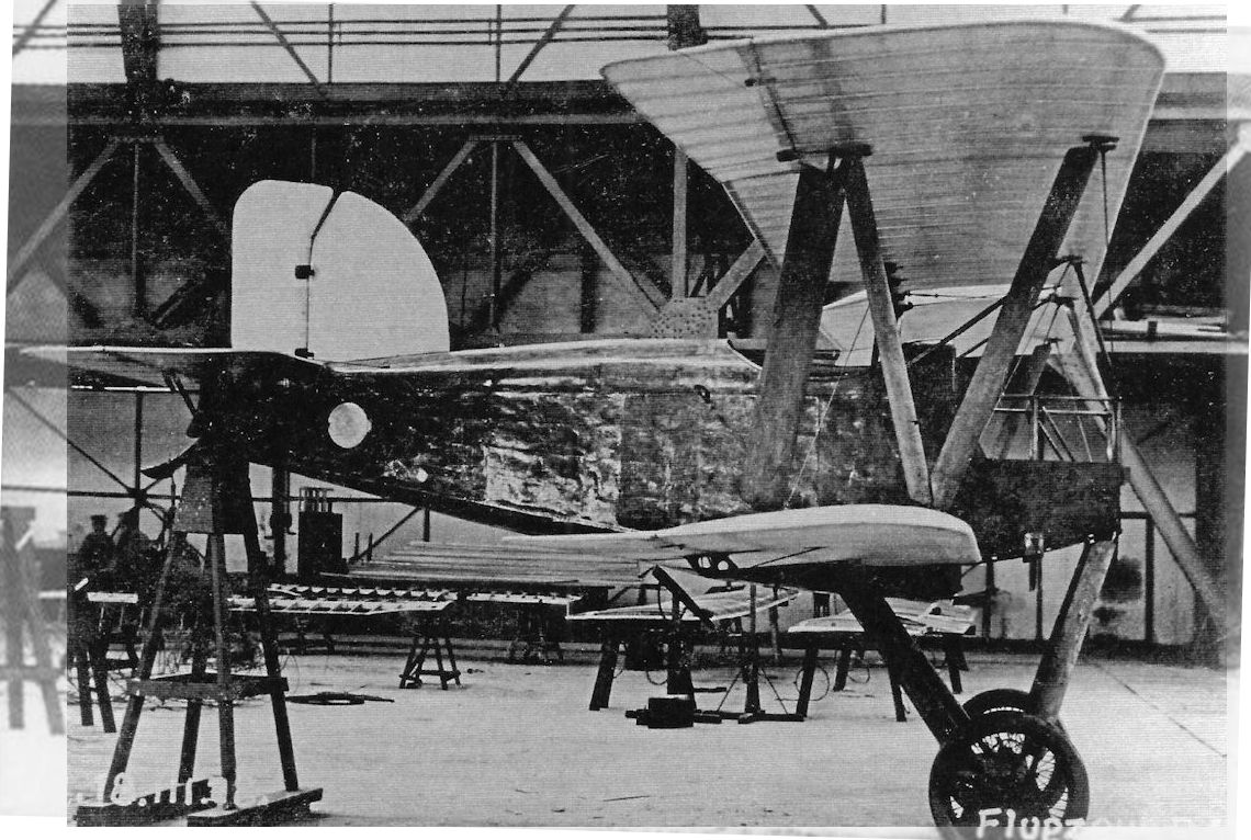
The next Schutte-Lanz fighter prototype was the D.IV, shown here before its engine was installed in March 1918.The engine was an experimental 195 hp Benz Bz.IIIbo V-8.
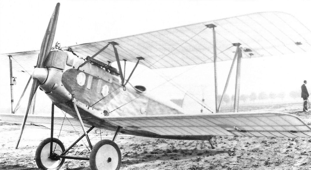
The Schutte-Lanz D.VII, powered by a high-compression 180 hp Mercedes D.IIIau, competed at the Second Fighter Competition. A workman-like design with frontal radiator and N-struts, it had average performance. The thin wing profile required wire bracing and did not offer the benign stall characteristics of Fokker's thick, rounded wing.
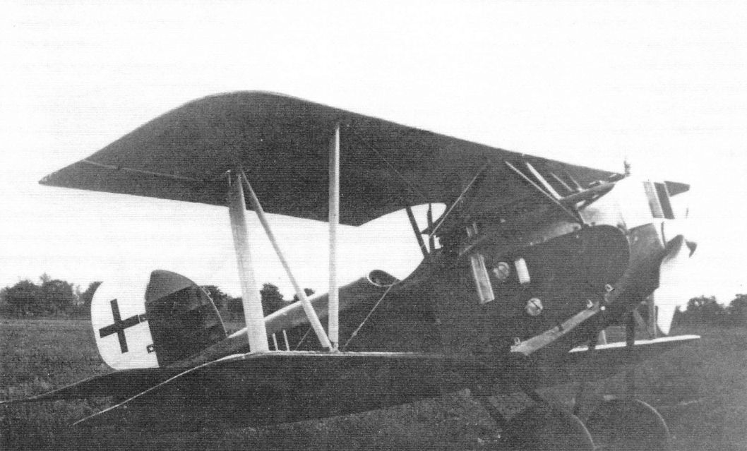
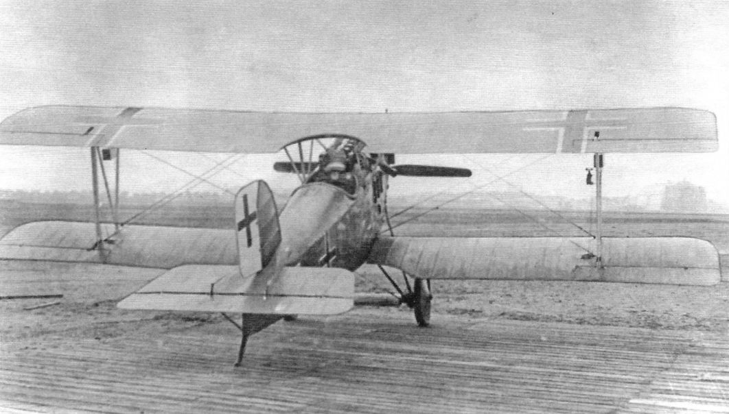
The Schutte-Lanz D.VII was the final fighter design built by Schutte-Lanz. With nose radiator and N-struts, it appeared to be influenced by the very successful Fokker D.VII then in combat. A workman-like design, it had a conventional thin wing and wire bracing. The secret to the Fokker's success was its innovative thick airfoil wing that was very strong, eliminated the need for extensive wire bracing which reduced drag, and offered excellent flying qualities. The Schutte-Lanz D.VII had none of these advances and thus no chance for production.
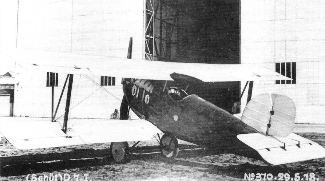
The Schutte-Lanz D.VII, powered by a high-compression 180 hp Mercedes D.IIIau, competed at the Second Fighter Competition. Its thin wing profile required significant wire bracing and did not offer the low drag, strength, and benign stall characteristics of Fokker's thick, rounded wing.
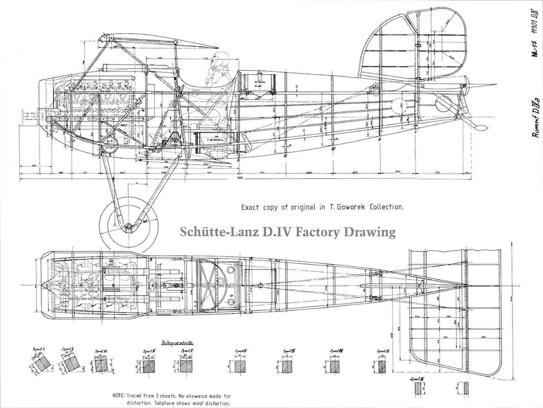
Schutte-Lanz D.IV Factory Drawing
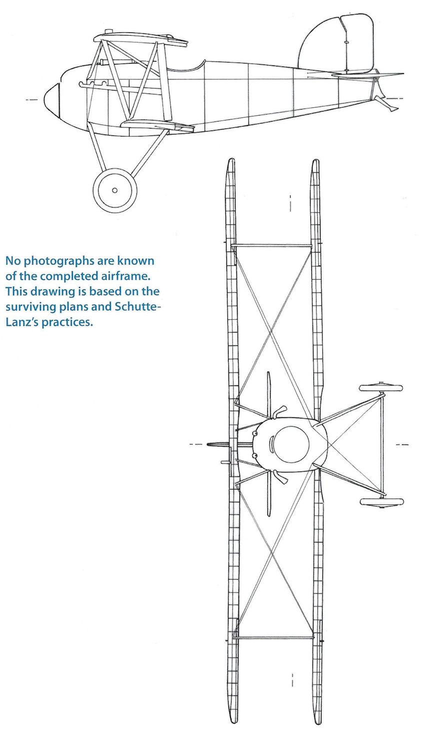
Schutte-Lanz D.IV. No photographs are known of the completed airframe. This drawing is based on the surviving plans and Schutte-Lanz's practices.
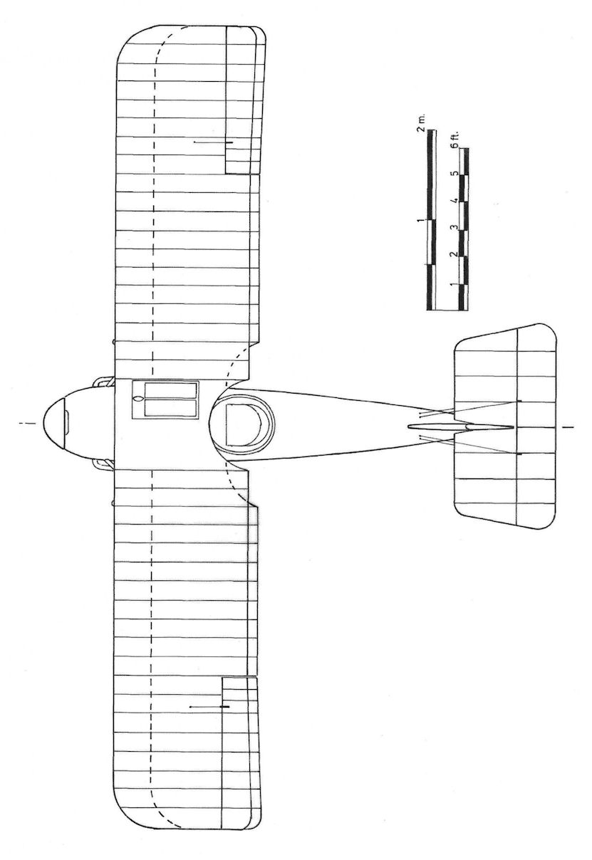
Schutte-Lanz D.IV
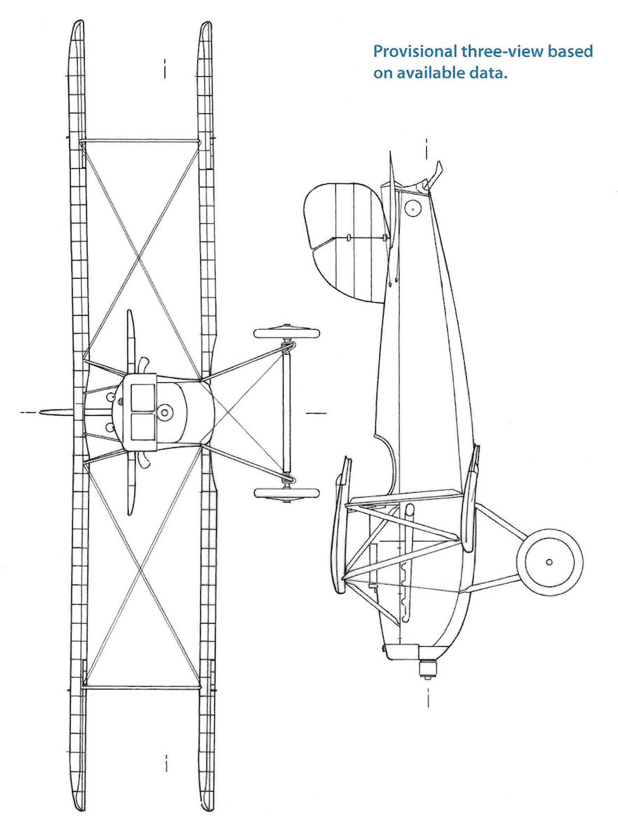
Schutte-Lanz D.IVa. Provisional three-view based on available data.
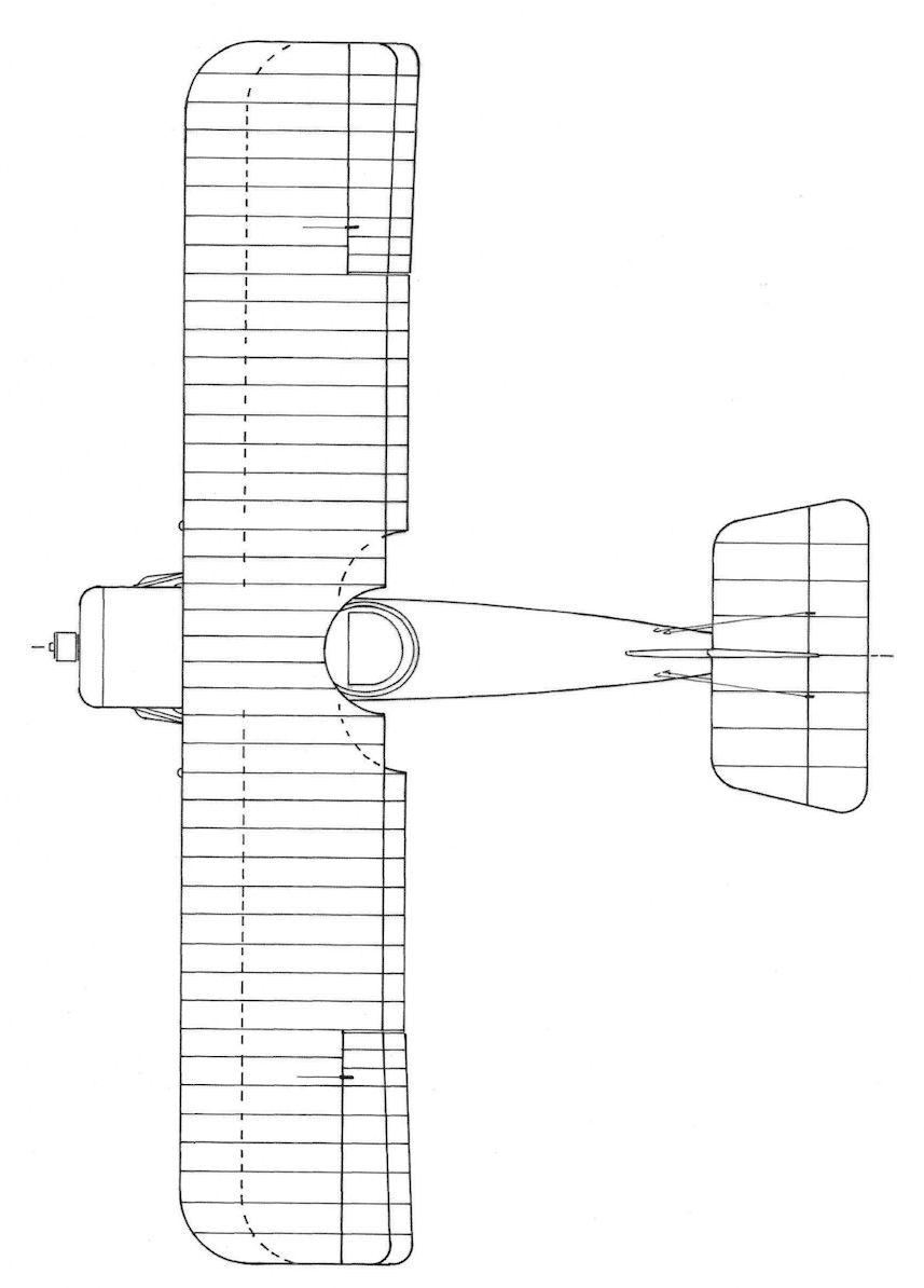
Schutte-Lanz D.IVa
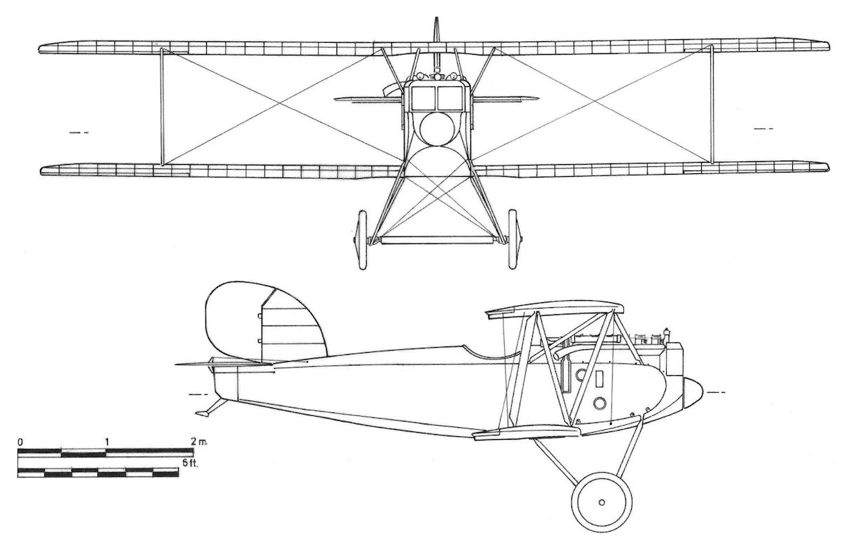
Schutte-Lanz D.VII
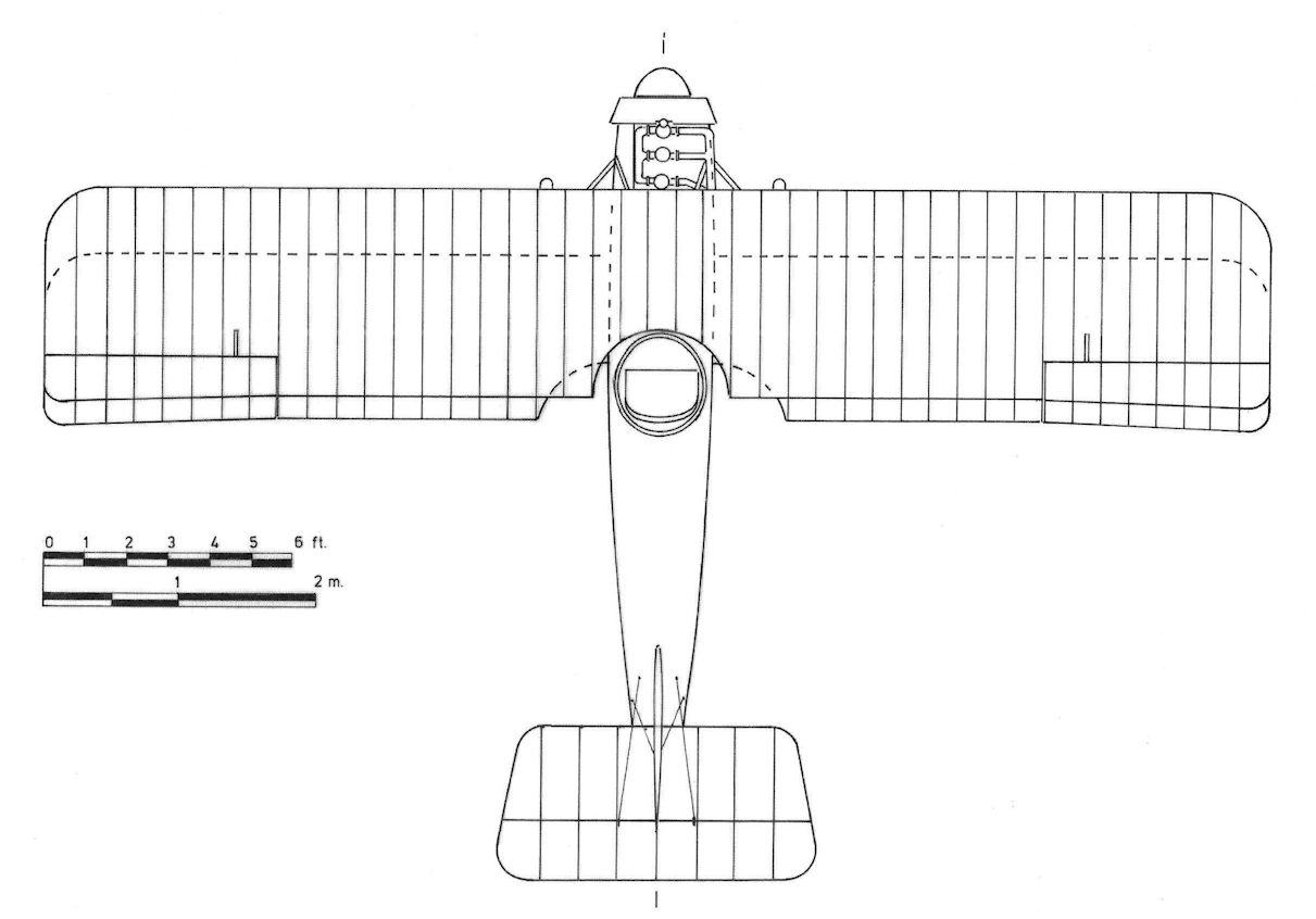
Schutte-Lanz D.VII
Schutte-Lanz Dr.I
The Schutte-Lanz Dr.I has the dubious distinction of being the last triplane fighter submitted to the fighter competitions. By the time of its appearance, Germany's triplane craze was over and the additional weight and drag of the third wing reduced the aircraft's performance below that of the mediocre D.III biplane from which it was developed. Further development was abandoned.
Schutte-Lanz Dr.I Specifications
Engine: 160 hp Mercedes D.III
Wing: Span 8.00 m
General: Length 6.26 m
Loaded Weight 900 kg
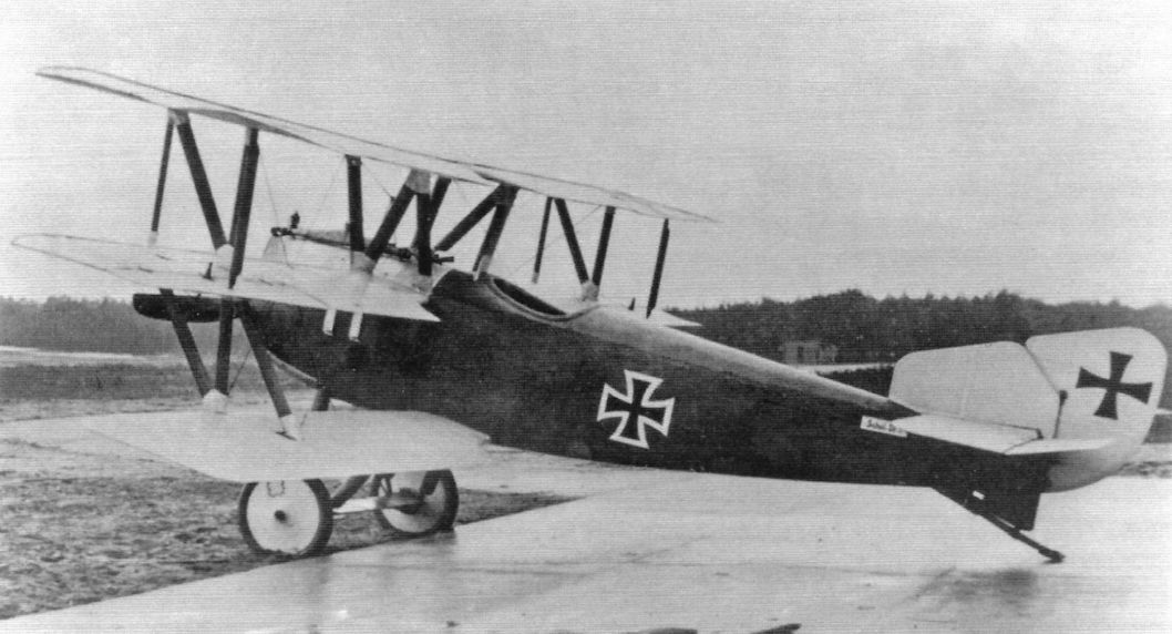
The Schutte-Lanz Dr.I was a triplane derivative of the Schutte-Lanz D.III fighter prototype and like it was powered by the 160 hp Mercedes D.III engine.

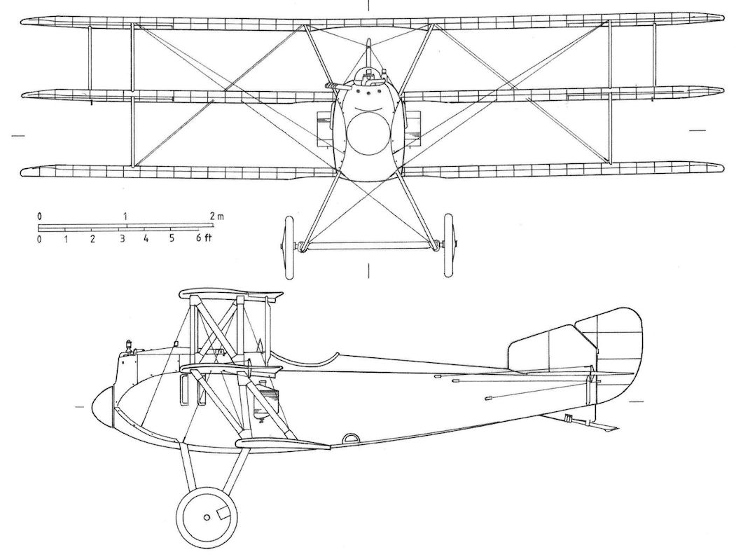
Schutte-Lanz Dr.I
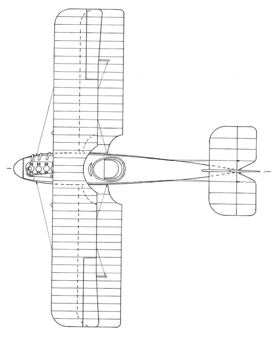
Schutte-Lanz Dr.I
Schutte-Lanz D.V a D.VI
The Schutte-Lanz D.V remained a project. It was to be powered by a Mercedes D.III with compressor (supercharger) that did not become available.
The next Schutte-Lanz fighter to fly was the D.VI powered by a Mercedes D.III engine. It was a parasol monoplane,- the wings were braced by large parallel struts with a supplemental airfoil between them. The prototype crashed May 29, 1918 and was not rebuilt.
Schutte-Lanz Fighter Specifications
D.III D.IV D.VI D.VII
Engine 160 hp Mercedes D.III 195 hp Benz B.IIIbo V-8 160 hp Mercedes D.III 180 hp Mercedes D.IIIau
Span, m 8.0 9.0 10.8 9.0
Chord, upper, m 1.5 1.5 1.6 1.5
Chord, lower, m 1.2 1.2 1.3 1.2
Wing area, m2 20.0 23.3 23.7 24.3
Length, m 6.5 5.8 6.65 6.0
Height, m 3.1 2.963 2.64 3.1
Wt, empty, kg 645 710 800 630
Wt, loaded, kg 860 900 980 810
Max. speed, kmh 195 180
Climb, 1000 m 3.0 min 2.8 min
Climb, 2000 m 5.8 min
Climb, 3000 m 9.7 min
Climb, 4000 m 14.8 min
Climb, 5000 m 31.9 min 14 min 21.3 min
Climb, 6000 m 29.6 min
Climb, 7000 m 29.6 min
Climb, 8000 m 45.5 min
Ceiling, m 8000
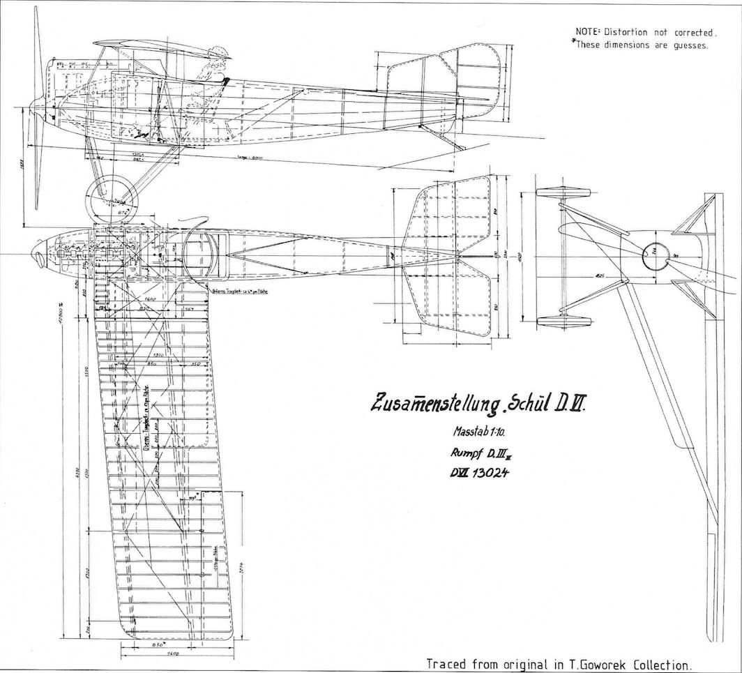
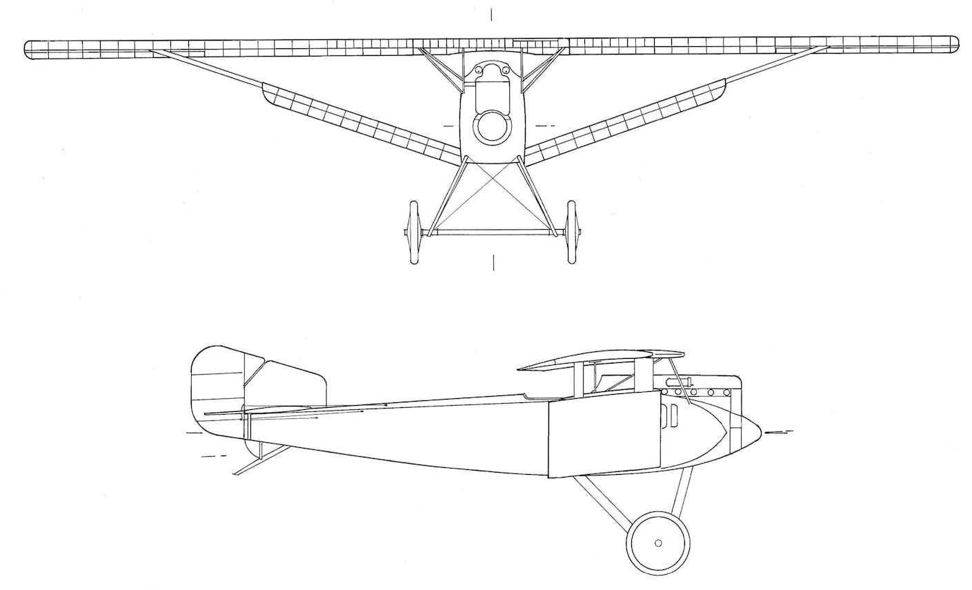
Schutte-Lanz D.VI
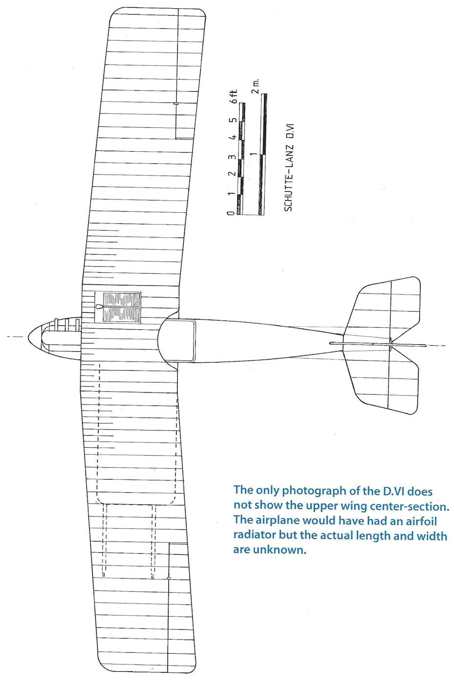
Schutte-Lanz D.VI. The only photograph of the D.VI does not show the upper wing center-section. The airplane would have had an airfoil radiator but the actual length and width are unknown.
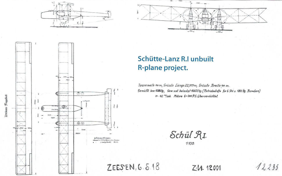
Schutte-Lanz R.I unbuilt R-plane project.
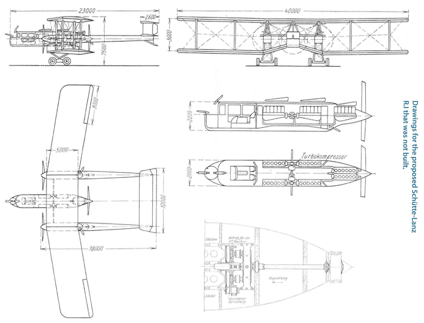
Drawings for the proposed Schutte-Lanz R.I that was not built.
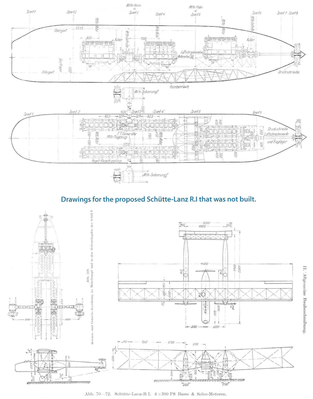
Drawings for the proposed Schutte-Lanz R.I that was not built.
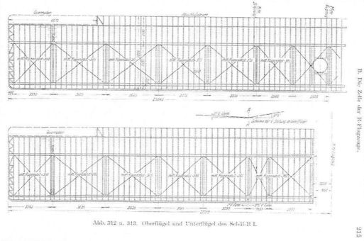
Schutte-Lanz designed an R-plane that was not built. This is a drawing of its wing structure
Schwade
Engineer Otto Schwade began working in 1880 and was interested in the technique of flight. He built the large glider that Otto Lilienthal flew but in which he crashed and was killed. Schwade's son, Hans James, learned to fly in 1910 in a Farman biplane at Mourmelon, France, and in June he gained his German Licence No. 9a. Around this time Schwade built his first aircraft, a Farman copy with a Schwade motor of 50 hp. This machine proved quite successful, the younger Schwade flying it in the Flugwoche at Berlin-Johannisthal, the 1912 Nordmarkflug, and in the Prinz Heinrich Wettbewerb.
After the National Flugspende the firm opened a flying school and on 23 March 1914, Henning remained aloft for 8 hours 10 minutes in a Schwade school biplane. This was a duration record for rotary engine aircraft. During the war the Schwade company repaired Albatros and Rumpler biplanes. They also built compressors for aviation engines (e.g. Mercedes 200 hp and for rotary engines). They also manufactured copies of the 50 and 100 hp Gnome rotary (Oberursel?); 75 engines of this type were delivered to the Government after the armistice. Two fighter aircraft were developed during the war but did not enter production. About 700 were employed at the factory in 1918.
When the IAACC visited the Erfurt factory of Otto Schwade on 22 February 1920, it found 45 aircraft and 36 engines. Since 1919 the Schwade factory resumed its pre-war manufacturing of automatic pumps and all models of centrifugal pumps. By June 1920 the workforce had dropped to 20 workers.
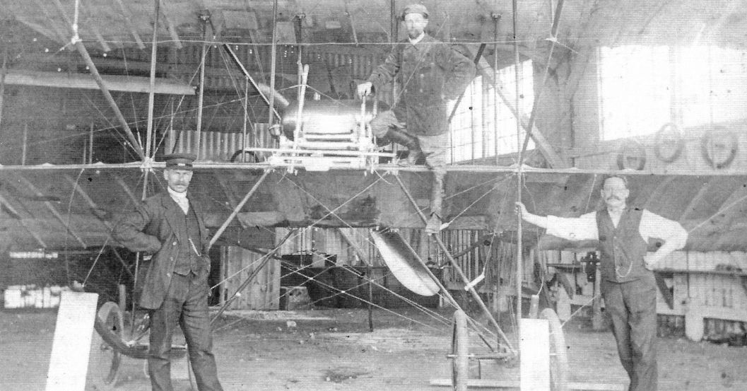
Pre-war Schwade biplane in the factory (Peter M. Grosz collection, STDB)
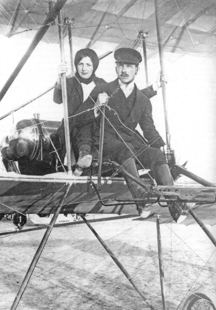
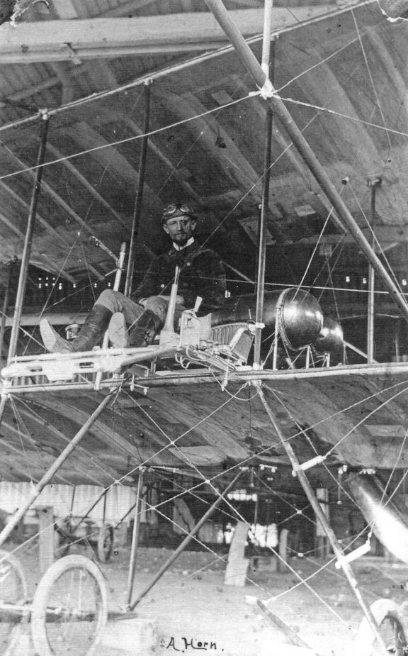
Pre-war Schwade biplane with trainee. (Peter M. Grosz collection, STDB)
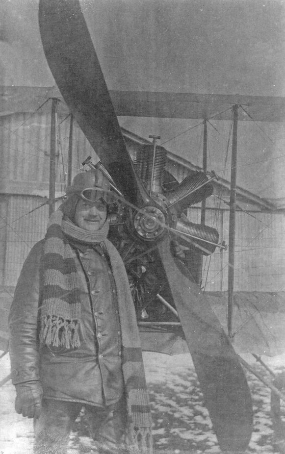
Pre-war Schwade biplane with trainee. (Peter M. Grosz collection, STDB)
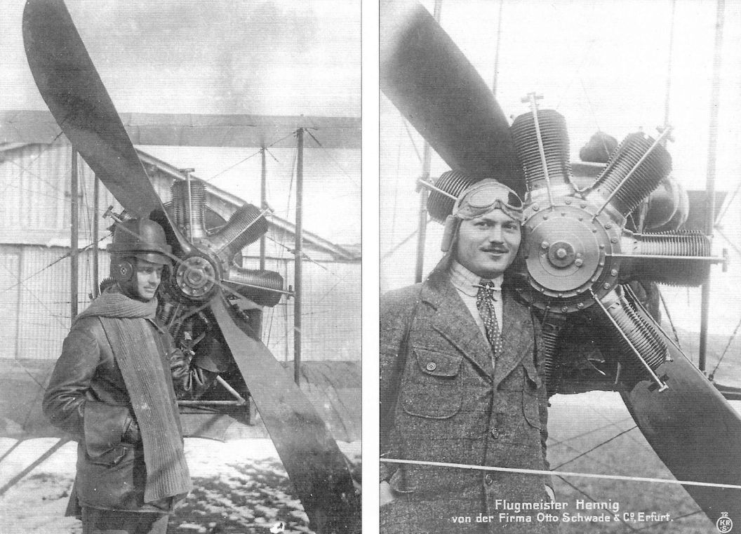
Pre-war Schwade biplane with trainees. (Peter M. Grosz collection, STDB)
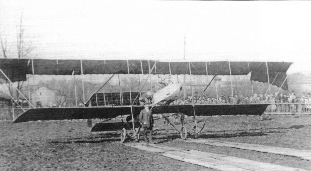
Pre-war Schwade front-elevator biplane with pilots and ground crew. (Peter M. Grosz collection, STDB)
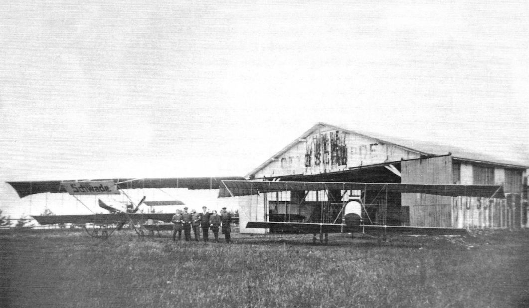
Schwade biplanes outside of the Schwade flying school. (Peter M. Grosz collection, STDB)
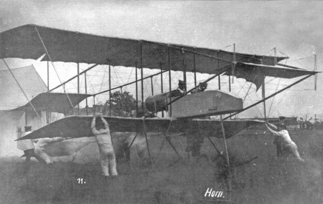
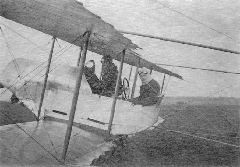
Pre-war Schwade Caudron-copy biplane with pilots. (Peter M. Grosz collection, STDB)
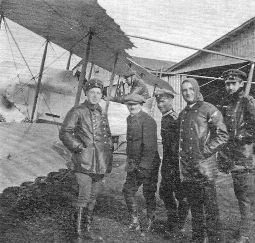
Pre-war Schwade Caudron-copy biplane with student pilots. (Peter M. Grosz collection, STDB)
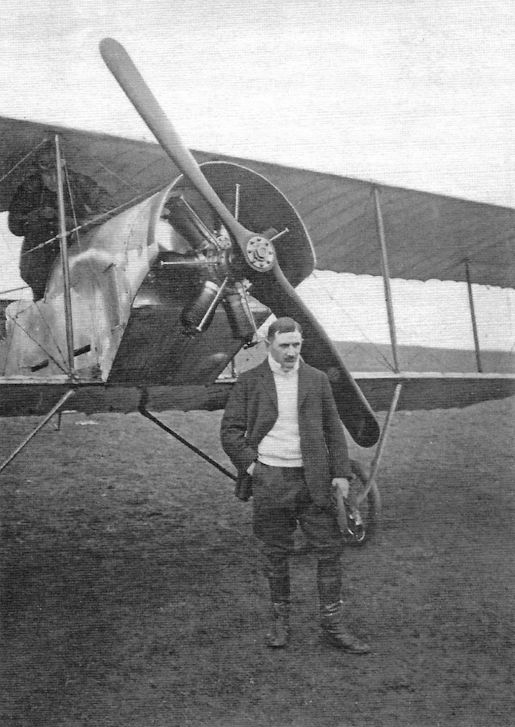
Pre-war Schwade Caudron-copy biplane with trainee. (Peter M. Grosz collection, STDB)
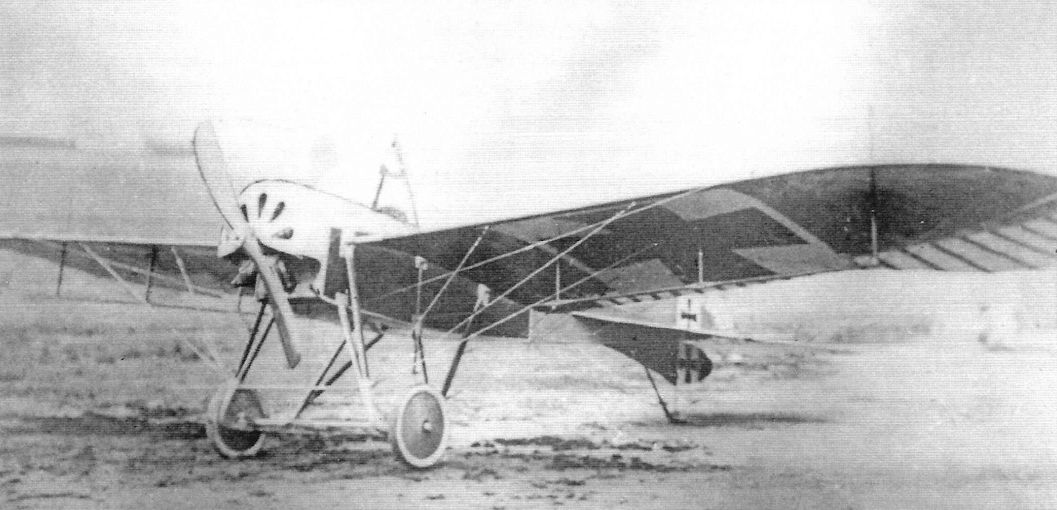
Like most German manufacturers, Schwade built a Taube in 1912/13.The Schwade Taube was powered by an 80 hp rotary built by Schwade. (Peter M. Grosz collection, STDB)
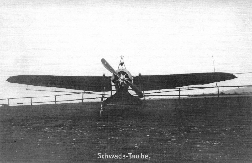
1912: Conversion of an Etrich Taube to an 80 hp Stahlherz engine. This two-seater reached 85 km/h.
Schwade
Engineer Otto Schwade began working in 1880 and was interested in the technique of flight. He built the large glider that Otto Lilienthal flew but in which he crashed and was killed. Schwade's son, Hans James, learned to fly in 1910 in a Farman biplane at Mourmelon, France, and in June he gained his German Licence No. 9a. Around this time Schwade built his first aircraft, a Farman copy with a Schwade motor of 50 hp. This machine proved quite successful, the younger Schwade flying it in the Flugwoche at Berlin-Johannisthal, the 1912 Nordmarkflug, and in the Prinz Heinrich Wettbewerb.
After the National Flugspende the firm opened a flying school and on 23 March 1914, Henning remained aloft for 8 hours 10 minutes in a Schwade school biplane. This was a duration record for rotary engine aircraft. During the war the Schwade company repaired Albatros and Rumpler biplanes. They also built compressors for aviation engines (e.g. Mercedes 200 hp and for rotary engines). They also manufactured copies of the 50 and 100 hp Gnome rotary (Oberursel?); 75 engines of this type were delivered to the Government after the armistice. Two fighter aircraft were developed during the war but did not enter production. About 700 were employed at the factory in 1918.
When the IAACC visited the Erfurt factory of Otto Schwade on 22 February 1920, it found 45 aircraft and 36 engines. Since 1919 the Schwade factory resumed its pre-war manufacturing of automatic pumps and all models of centrifugal pumps. By June 1920 the workforce had dropped to 20 workers.
Engineer Otto Schwade began working in 1880 and was interested in the technique of flight. He built the large glider that Otto Lilienthal flew but in which he crashed and was killed. Schwade's son, Hans James, learned to fly in 1910 in a Farman biplane at Mourmelon, France, and in June he gained his German Licence No. 9a. Around this time Schwade built his first aircraft, a Farman copy with a Schwade motor of 50 hp. This machine proved quite successful, the younger Schwade flying it in the Flugwoche at Berlin-Johannisthal, the 1912 Nordmarkflug, and in the Prinz Heinrich Wettbewerb.
After the National Flugspende the firm opened a flying school and on 23 March 1914, Henning remained aloft for 8 hours 10 minutes in a Schwade school biplane. This was a duration record for rotary engine aircraft. During the war the Schwade company repaired Albatros and Rumpler biplanes. They also built compressors for aviation engines (e.g. Mercedes 200 hp and for rotary engines). They also manufactured copies of the 50 and 100 hp Gnome rotary (Oberursel?); 75 engines of this type were delivered to the Government after the armistice. Two fighter aircraft were developed during the war but did not enter production. About 700 were employed at the factory in 1918.
When the IAACC visited the Erfurt factory of Otto Schwade on 22 February 1920, it found 45 aircraft and 36 engines. Since 1919 the Schwade factory resumed its pre-war manufacturing of automatic pumps and all models of centrifugal pumps. By June 1920 the workforce had dropped to 20 workers.
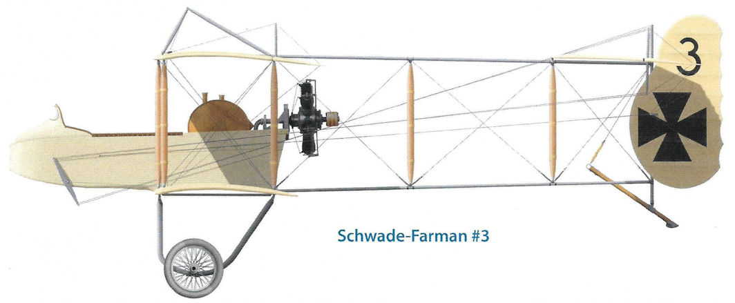
Schwade-Farman #3
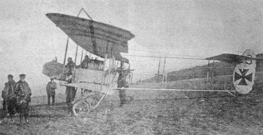
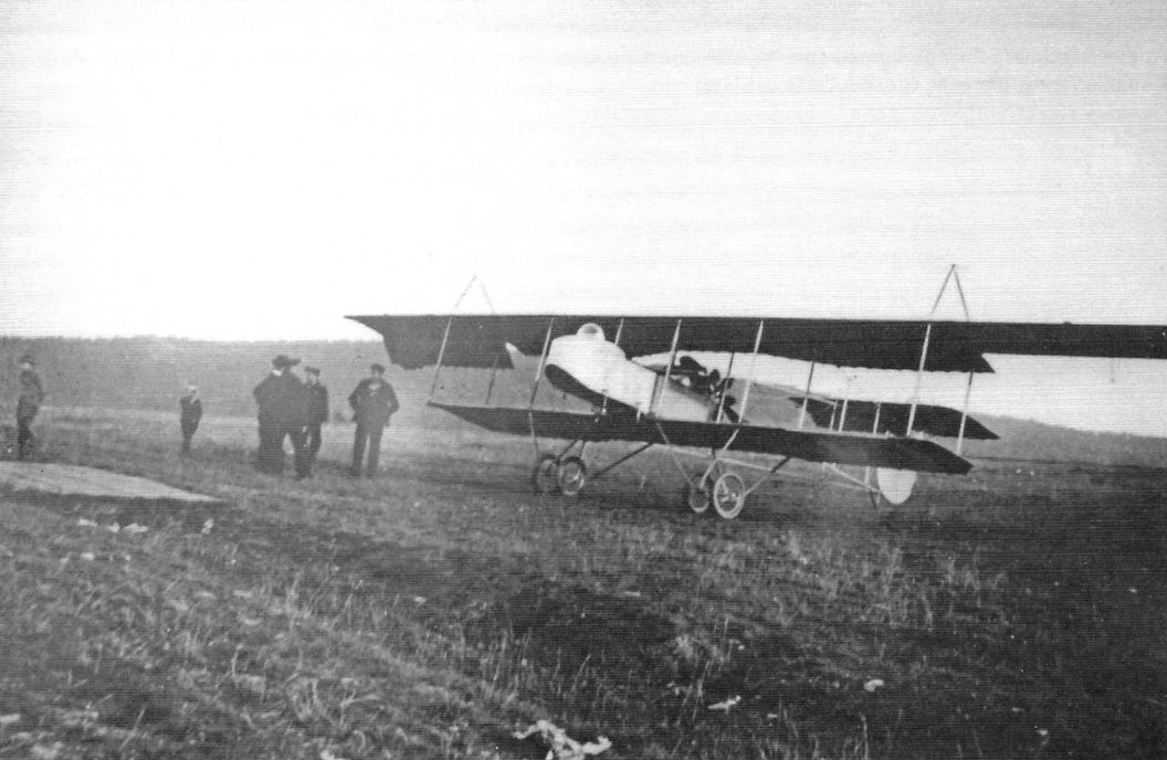
Schwade Farman-copy biplane with air and ground crew.(Peter M. Grosz collection, STDB)
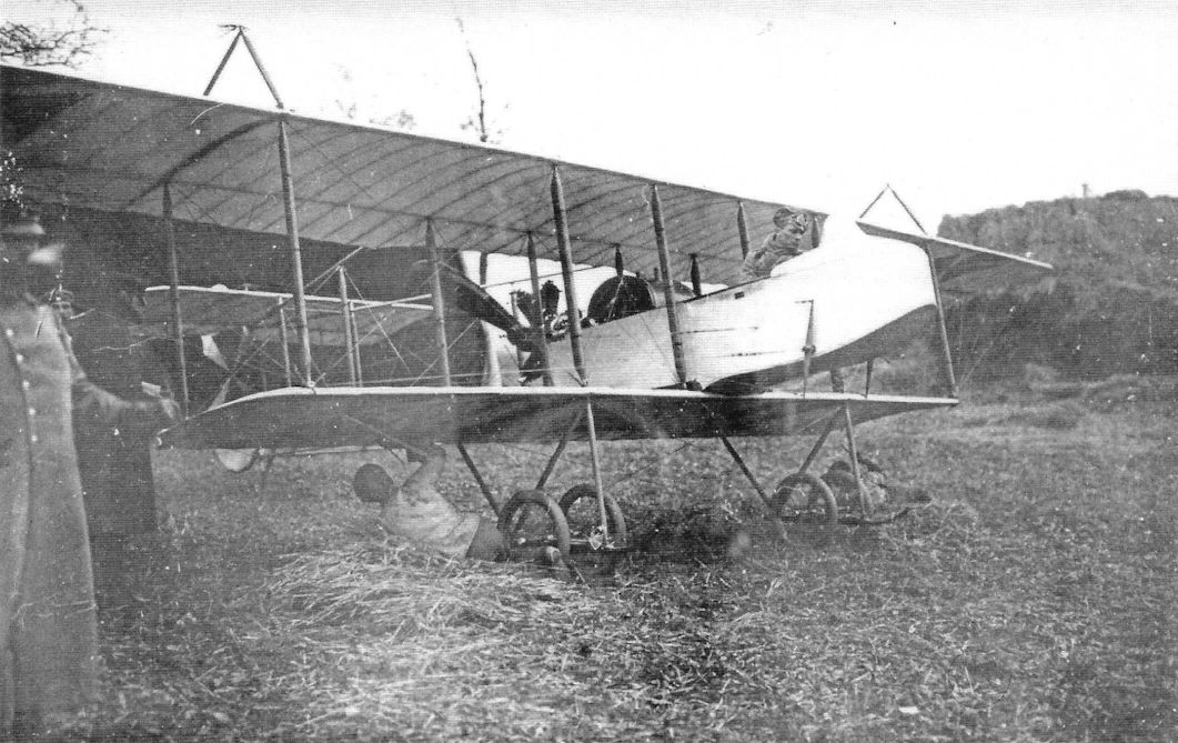
Schwade Farman-copy biplane. Power was from a 50 hp rotary built by Schwade. (Peter M. Grosz collection, STDB)
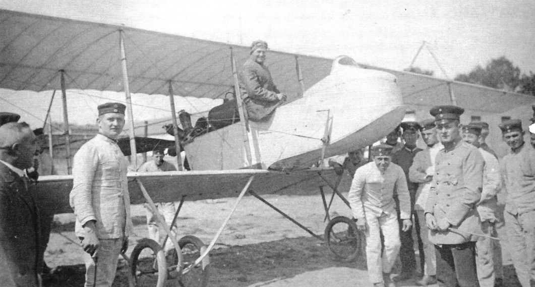
Schwade Farman-copy trainer with air and ground crew. (Peter M. Grosz collection, STDB)
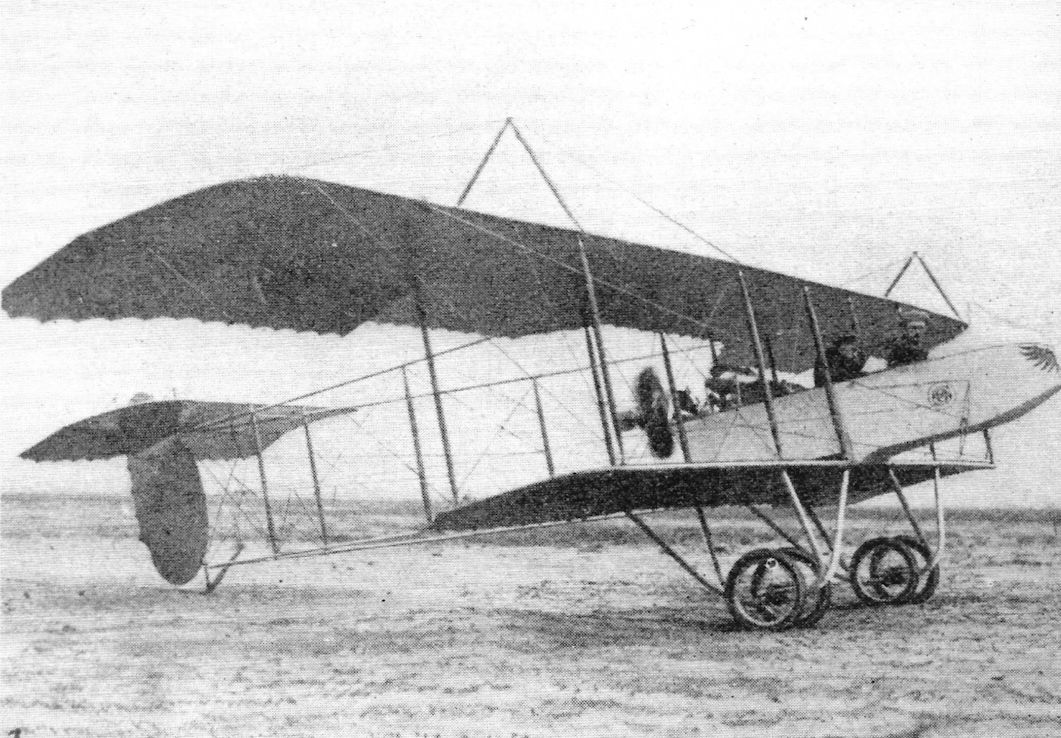
Schwade Farman-copy biplane carrying logo on its nose. (Peter M. Grosz collection, STDB)
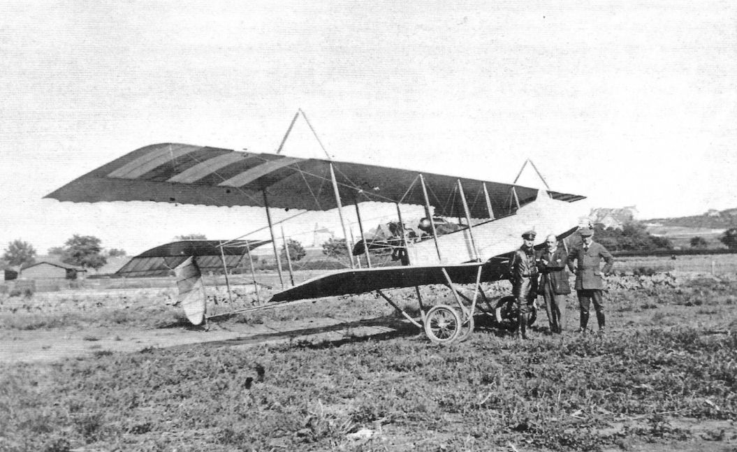
Schwade Farman-copy biplane with air and ground crew. The aircraft carries an unusual marking on its wing. (Peter M. Grosz collection, STDB)
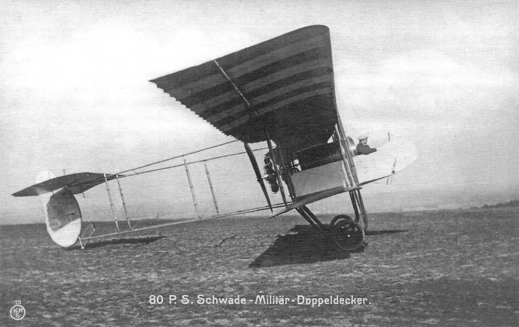
Schwade Military Biplane powered by an 80 hp rotary. (Peter M. Grosz collection, STDB)
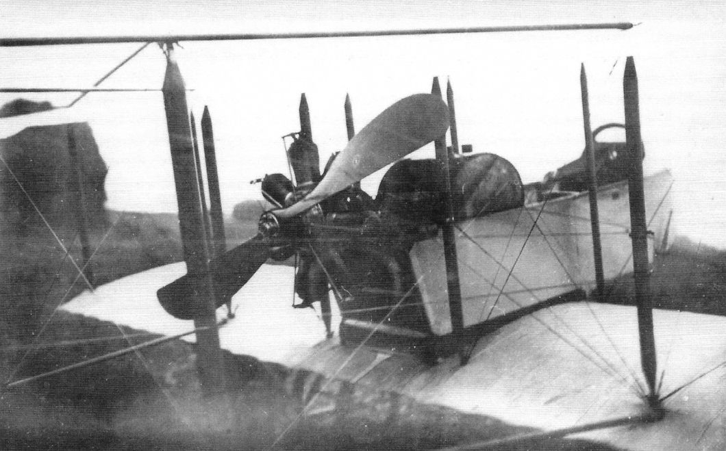
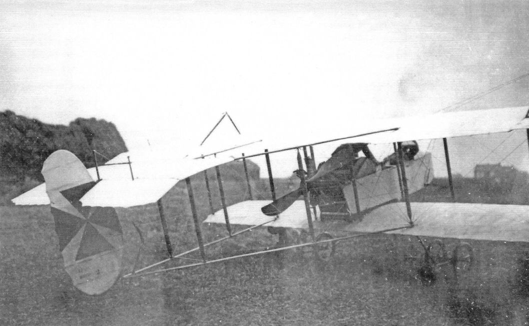
Schwade Farman-copy biplane with pilots. The aircraft below carries early national insignia. (Peter M. Grosz collection, STDB)
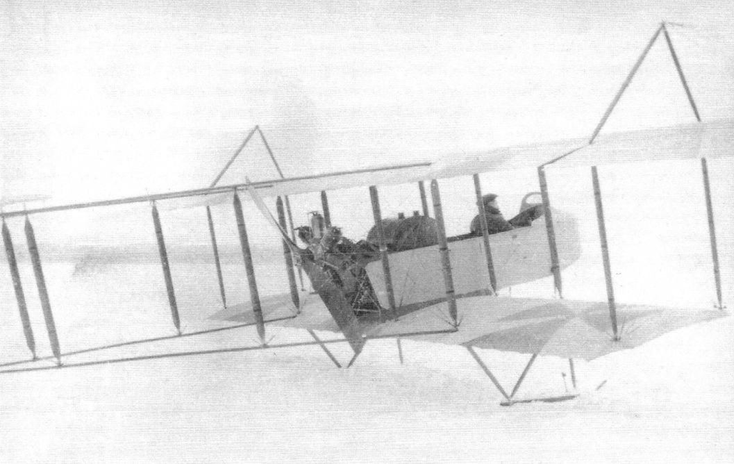
Schwade Farman-copy biplane with pilots. The aircraft is on skis and carries early national insignia. (Peter M. Grosz collection, STDB)
Schwade biplanes outside of the Schwade flying school. (Peter M. Grosz collection, STDB)
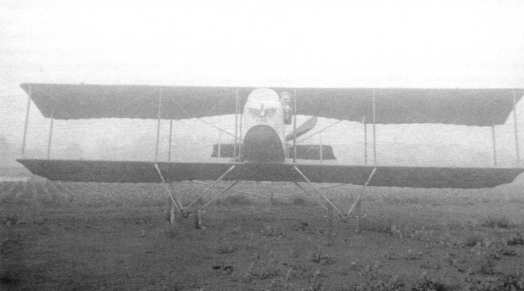
Schwade Farman-copy biplane carrying logo on its nose. The aircraft has a more modern, simplified wing. (Peter M. Grosz collection, STDB)
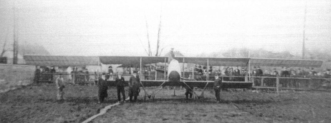
Schwade Farman-copy biplanes with pilots and ground crew. Power was from a 50 hp rotary built by Schwade. (Peter M. Grosz collection, STDB)
Schwade
Engineer Otto Schwade began working in 1880 and was interested in the technique of flight. He built the large glider that Otto Lilienthal flew but in which he crashed and was killed. Schwade's son, Hans James, learned to fly in 1910 in a Farman biplane at Mourmelon, France, and in June he gained his German Licence No. 9a. Around this time Schwade built his first aircraft, a Farman copy with a Schwade motor of 50 hp. This machine proved quite successful, the younger Schwade flying it in the Flugwoche at Berlin-Johannisthal, the 1912 Nordmarkflug, and in the Prinz Heinrich Wettbewerb.
After the National Flugspende the firm opened a flying school and on 23 March 1914, Henning remained aloft for 8 hours 10 minutes in a Schwade school biplane. This was a duration record for rotary engine aircraft. During the war the Schwade company repaired Albatros and Rumpler biplanes. They also built compressors for aviation engines (e.g. Mercedes 200 hp and for rotary engines). They also manufactured copies of the 50 and 100 hp Gnome rotary (Oberursel?); 75 engines of this type were delivered to the Government after the armistice. Two fighter aircraft were developed during the war but did not enter production. About 700 were employed at the factory in 1918.
When the IAACC visited the Erfurt factory of Otto Schwade on 22 February 1920, it found 45 aircraft and 36 engines. Since 1919 the Schwade factory resumed its pre-war manufacturing of automatic pumps and all models of centrifugal pumps. By June 1920 the workforce had dropped to 20 workers.
Engineer Otto Schwade began working in 1880 and was interested in the technique of flight. He built the large glider that Otto Lilienthal flew but in which he crashed and was killed. Schwade's son, Hans James, learned to fly in 1910 in a Farman biplane at Mourmelon, France, and in June he gained his German Licence No. 9a. Around this time Schwade built his first aircraft, a Farman copy with a Schwade motor of 50 hp. This machine proved quite successful, the younger Schwade flying it in the Flugwoche at Berlin-Johannisthal, the 1912 Nordmarkflug, and in the Prinz Heinrich Wettbewerb.
After the National Flugspende the firm opened a flying school and on 23 March 1914, Henning remained aloft for 8 hours 10 minutes in a Schwade school biplane. This was a duration record for rotary engine aircraft. During the war the Schwade company repaired Albatros and Rumpler biplanes. They also built compressors for aviation engines (e.g. Mercedes 200 hp and for rotary engines). They also manufactured copies of the 50 and 100 hp Gnome rotary (Oberursel?); 75 engines of this type were delivered to the Government after the armistice. Two fighter aircraft were developed during the war but did not enter production. About 700 were employed at the factory in 1918.
When the IAACC visited the Erfurt factory of Otto Schwade on 22 February 1920, it found 45 aircraft and 36 engines. Since 1919 the Schwade factory resumed its pre-war manufacturing of automatic pumps and all models of centrifugal pumps. By June 1920 the workforce had dropped to 20 workers.
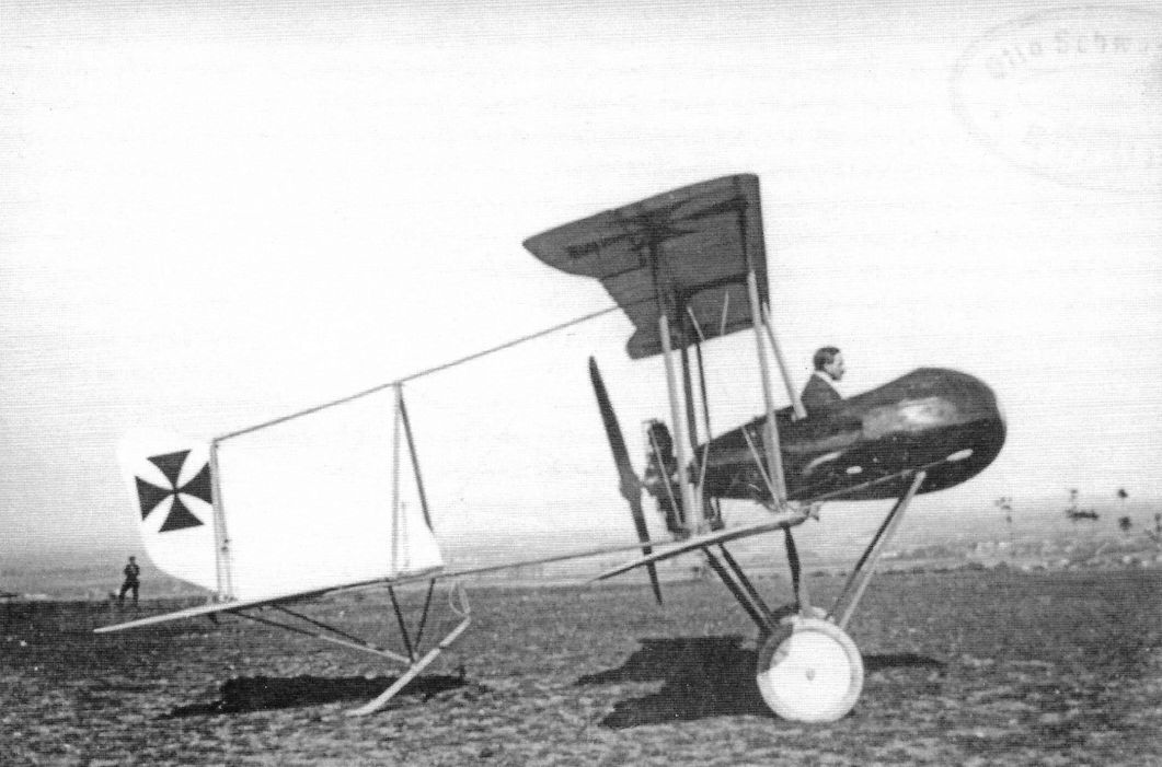
In 1914 Schwade built a single-seat pusher fighter prototype powered by an 80 hp rotary built by Schwade. (Peter M. Grosz collection, STDB)
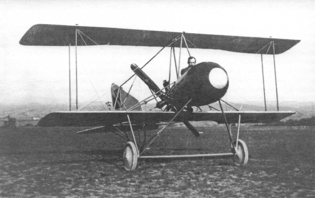

The Schwade 1914 single-seat fighter prototype powered by an 80 hp rotary built by Schwade. Some steel was used in the airframe construction. (Peter M. Grosz collection, STDB)
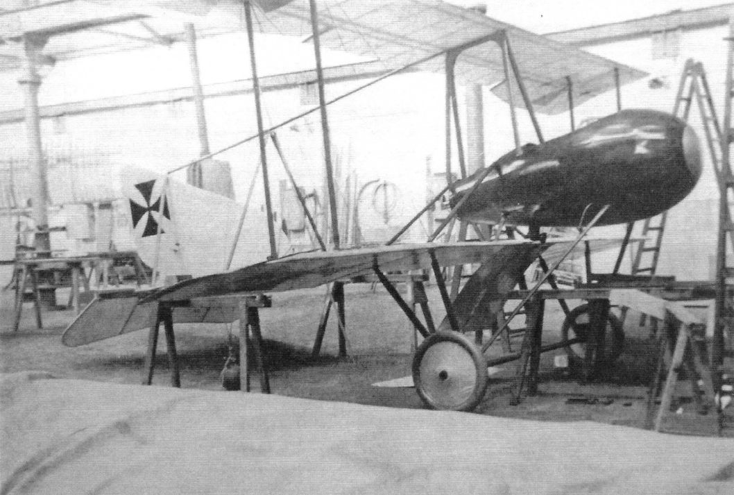
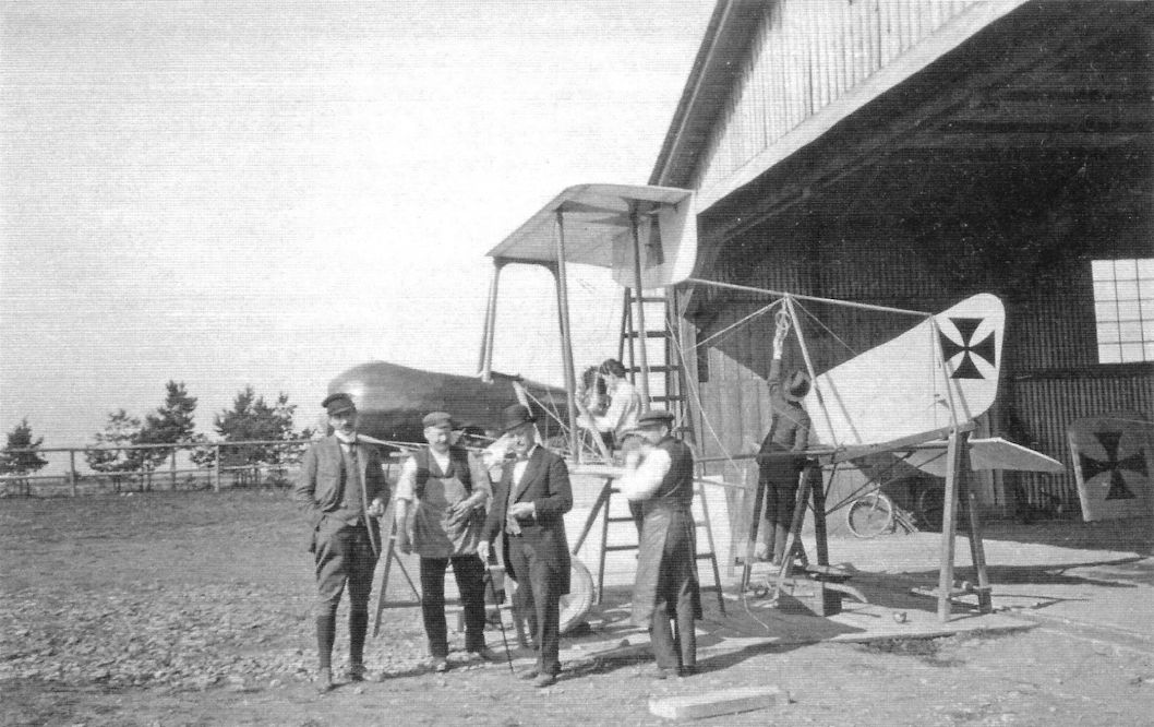
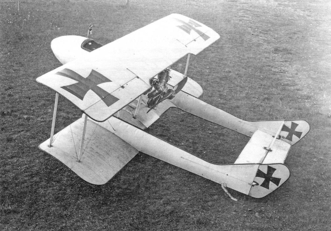
1916: Single-seat experimental aircraft. Biplane with twin fuselage and 110 hp Schwade Stahlherz engine. Designation: Schwade "C.II". No military use.
A Schwade Stahlherz engine was used to power the same company’s Nr 2 fighter.
A Schwade Stahlherz engine was used to power the same company’s Nr 2 fighter.
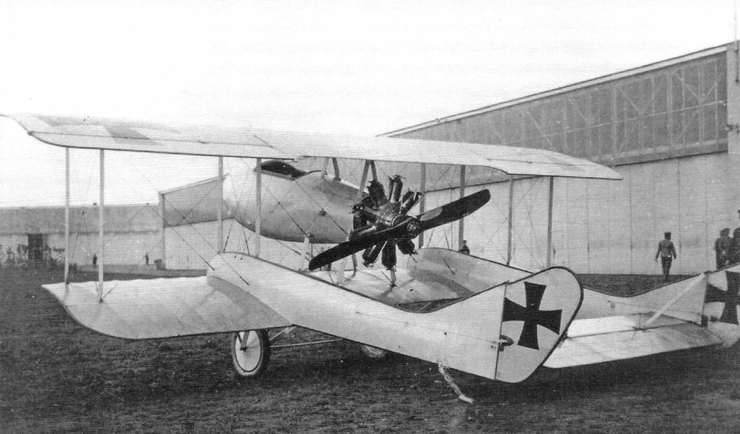
The Schwade 1915 single-seat pusher fighter prototype. (Peter M. Grosz collection, STDB)
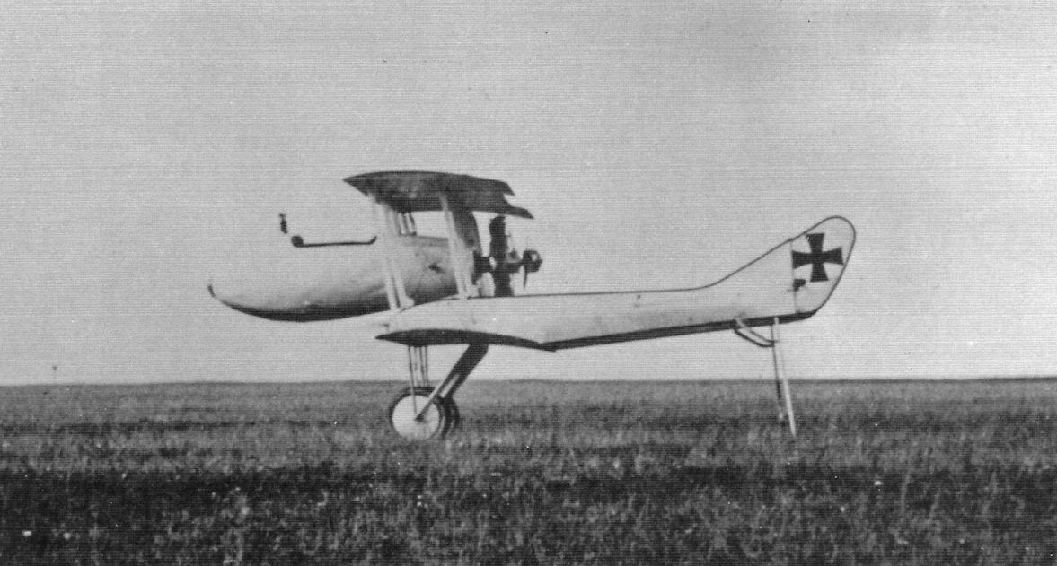
The Schwade 1915 single-seat pusher fighter prototype was powered by a 100 hp rotary built by Schwade. The design of the tail supports was lower drag than that for their 1914 fighter. The aircraft was finished in overall white with black borders, a scheme use for Pfalz Eindeckers and other aircraft of the time. (Peter M. Grosz collection, STDB)
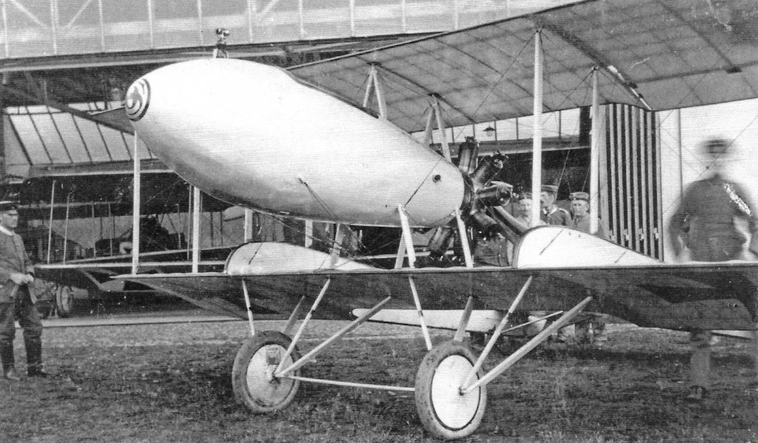
The Schwade 1915 single-seat pusher fighter prototype. (Peter M. Grosz collection, STDB)
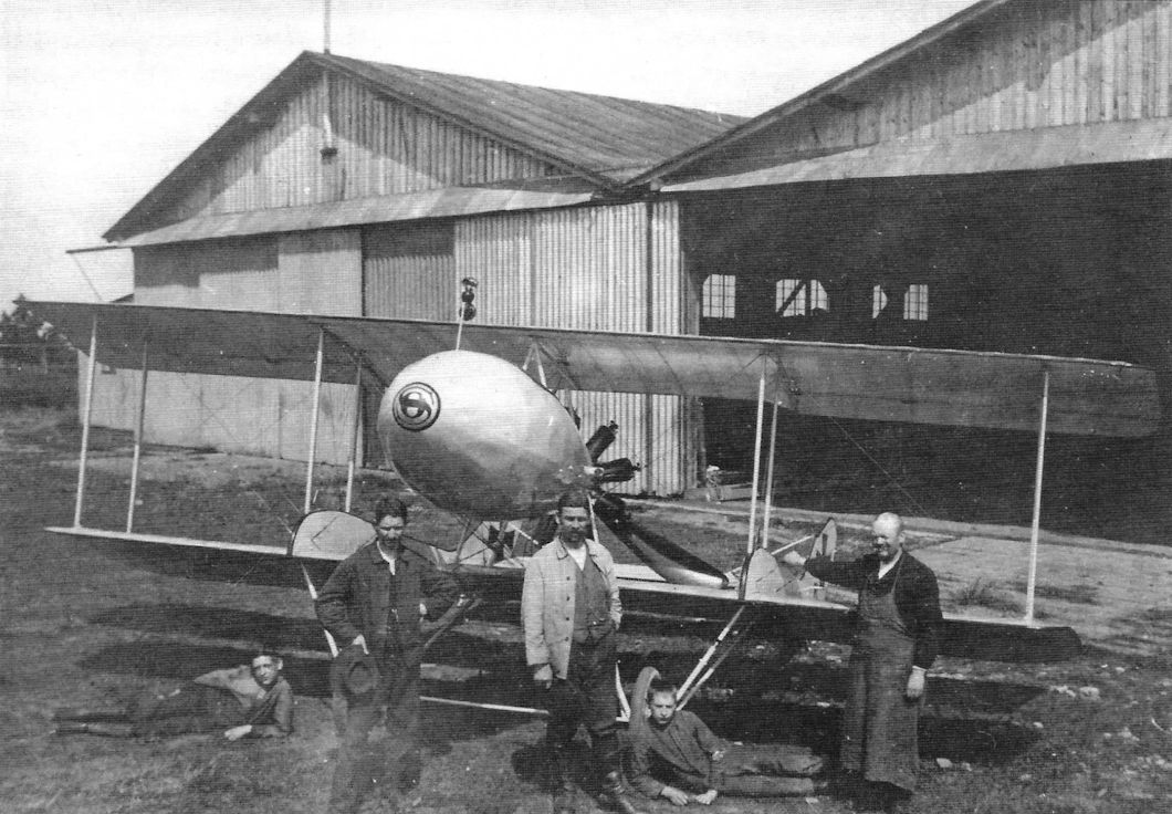
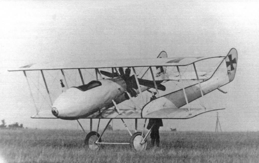
Retaining the twin-boom pusher layout of the Nr 1, the Nr 2 was better streamlined.
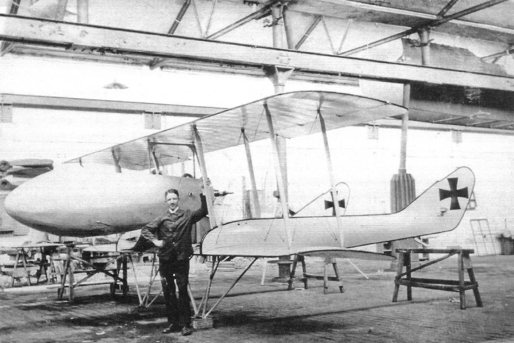
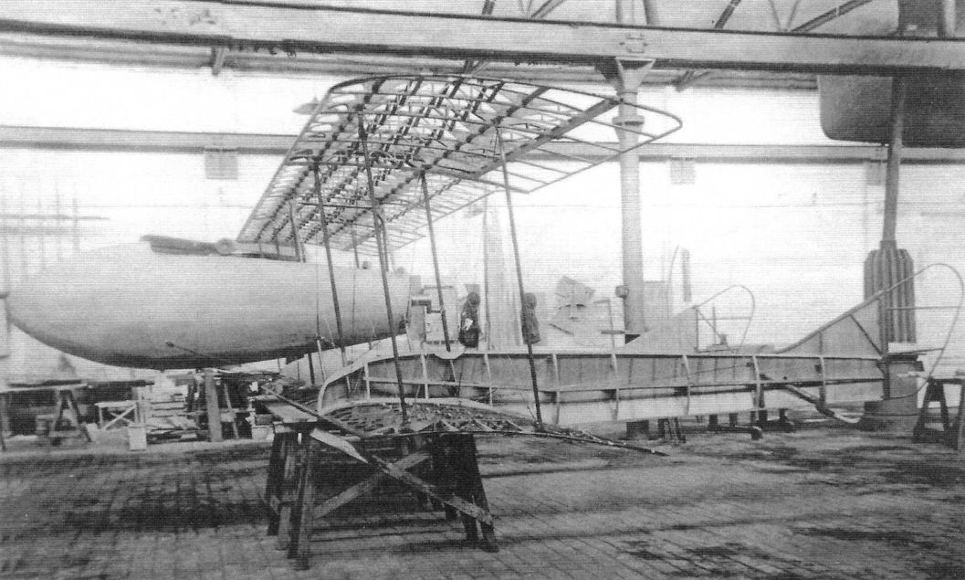
The Schwade 1915 single-seat pusher fighter prototype under construction. Again some steel was used in the structure. (Peter M. Grosz collection, STDB)
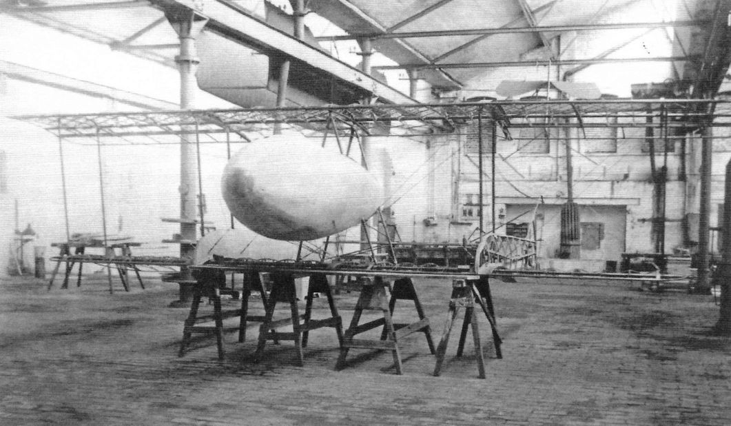
The Schwade 1915 single-seat pusher fighter prototype. (Peter M. Grosz collection, STDB)
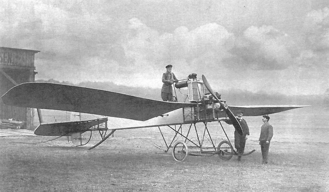
Pre-war Krieger - Prinz Sigismund.
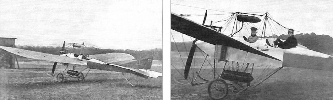
This machine was built by the Union-Flugzeugwerke GmbH in Berlin-Teltow (Germany), a really small prewar airplane factory which existed from 1912 to 1916. But there were some famous names in the history of the Union-Flugzeugwerke
Dr Josef Sablatnig (1868-1945) set with a Pfeil-Doppeldecker (constructed and built by Ing Karl Bomhard) a new world record on September 27, 1912 with three passengers to a height of 1,120 metres. By the end of 1912, the two were joined by Georg Konig and formed the Union-Flugzeugwerke GmbH in Berlin-Teltow (Germany). Up to 1916 it designed aircraft, but lack of orders led to the take-over of the company by the Norddeutsche Flugzeugwerke. The aircraft all had a characteristic wing in the shape of an arrow. This design proved to be insufficient and was later abandoned. In 1915 he constructed his first seaplane and in 1916 he formed the Sablatnig-Flugzeugbau GmbH in Berlin.
The unique Union Wasserdoppeldecker (biplane seaplane) was designed in 1913. The 3-bay floatplane was powered by a 120 hp Austro-Daimler engine. The machine was bought by the German Marine and got the designation 73 (if the German number painters were secure ). The machine crashed before the start of the war.
The Union-Flugzeugwerke made a few own designed aeroplanes. Almost unknown is the Union G.I (yes a Grossflugzeug) of 1915 with four (!) engines (115 hp Daimler). Is quoted as one of the first German 4-engined planes. The machine was not accepted by Idflieg, so the designation G.I may be spurious. Have never seen a picture or drawing of the Union G.I. So there are still machines to finds out.
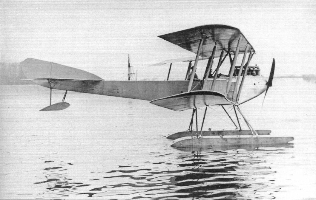
Union floatplane biplane; no national insignia were applied. (Peter M. Grosz collection, STDB)
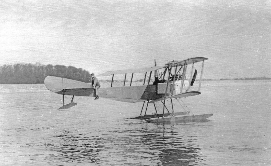
Union floatplane biplane with 100 hp Mercedes D.I engine with side radiators. (Peter M. Grosz collection, STDB)
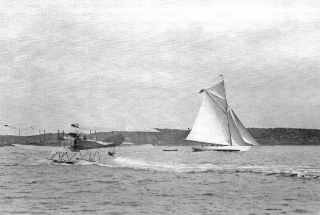
Union floatplane biplane taxiing. (Peter M. Grosz collection, STDB)
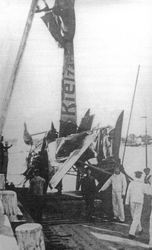
Union floatplane being fished out of the water after an accident. It was assigned to Kiel and the marine number appears to be 73. (Peter M. Grosz collection, STDB)
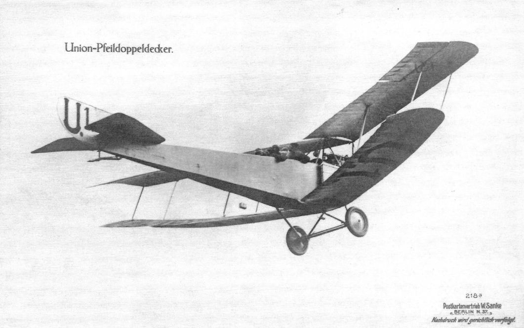
Union Arrow biplane with water-cooled engine in flight. The Union Arrows were powered by 100 hp inline engines from Argus, Daimler, and NAG.The photo was made into a Sanke card. (Peter M. Grosz collection, STDB)
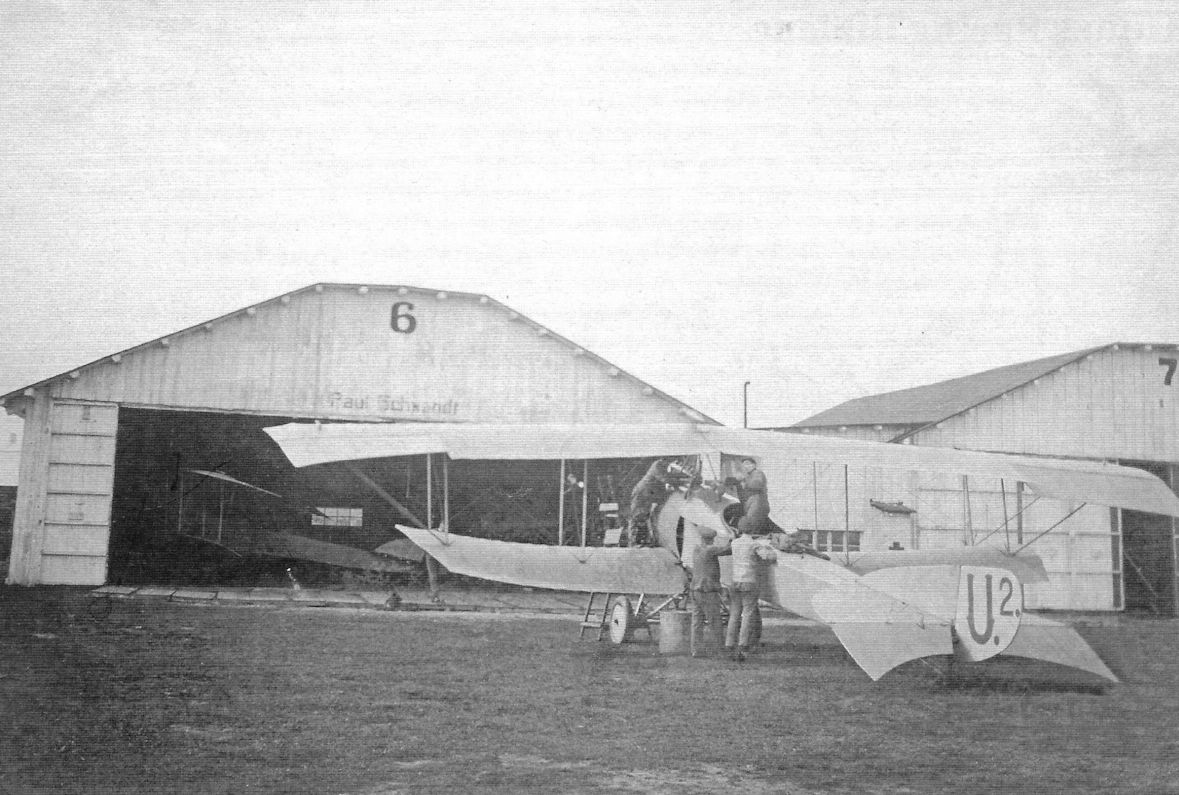
Union Racing Biplane designated "U.2" with 2 1/2 bays of bracing. The upward-curving lower wings and downward curving upper wings of this 2-bay design are distinctive. (Peter M. Grosz collection, STDB)
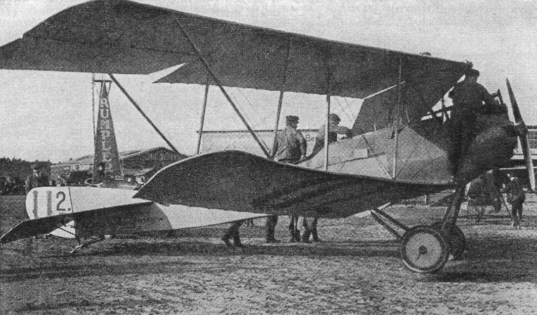
Union Arrow biplane. (Peter M. Grosz collection, STDB)
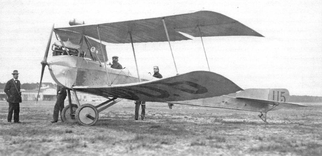
Union Arrow biplane with water-cooled engine. (Peter M. Grosz collection, STDB)
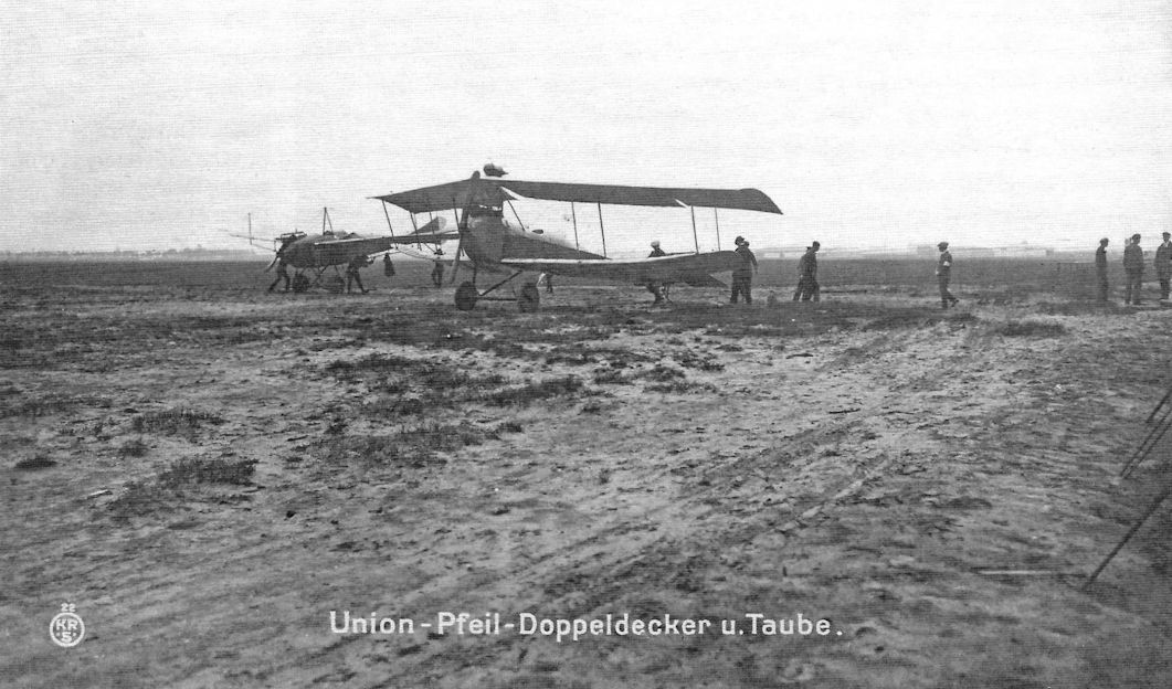
Union Arrow biplane with water-cooled engine and Union Taube. (Peter M. Grosz collection, STDB)
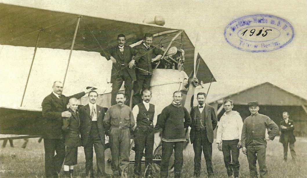
Union Arrow biplane with water-cooled engine with factory staff. (Peter M. Grosz collection, STDB)
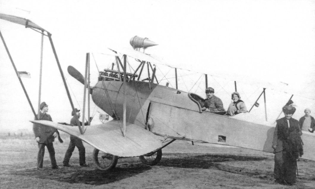
Union Racing Biplane.The engine appears to be a 100 hp Mercedes D.I. (Peter M. Grosz collection, STDB)
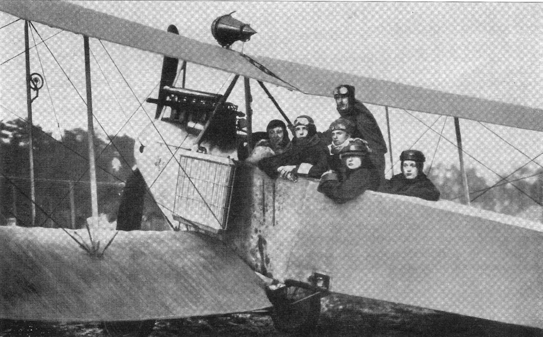
Union Racing Biplane with side radiator on the port side of the aircraft. (Peter M. Grosz collection, STDB)
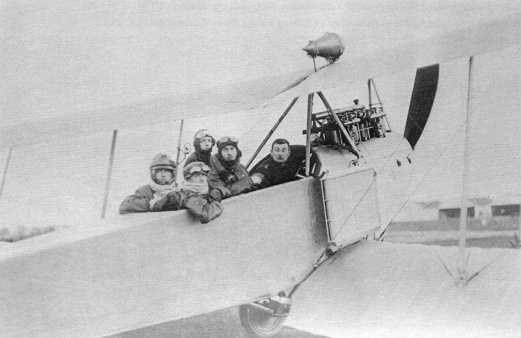
Union Racing Biplane. The spacious rear cockpit could accommodate several passengers. A side radiator was fitted. (Peter M. Grosz collection, STDB)
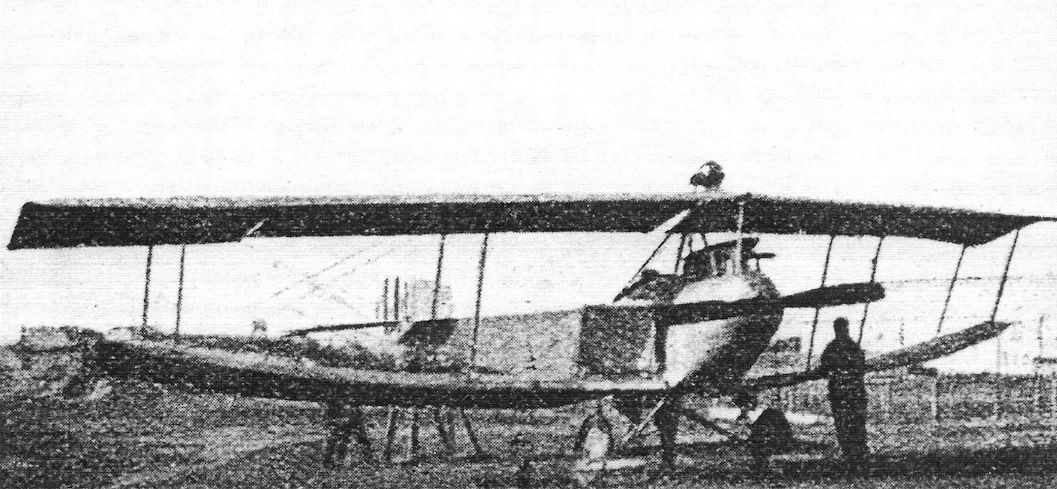
Union Racing Biplane with simplified 2-bay wing bracing. (Peter M. Grosz collection, STDB)
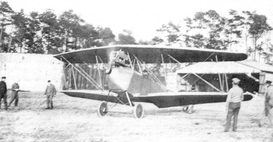
Union Arrow biplane with water-cooled engine. (Peter M. Grosz collection, STDB)
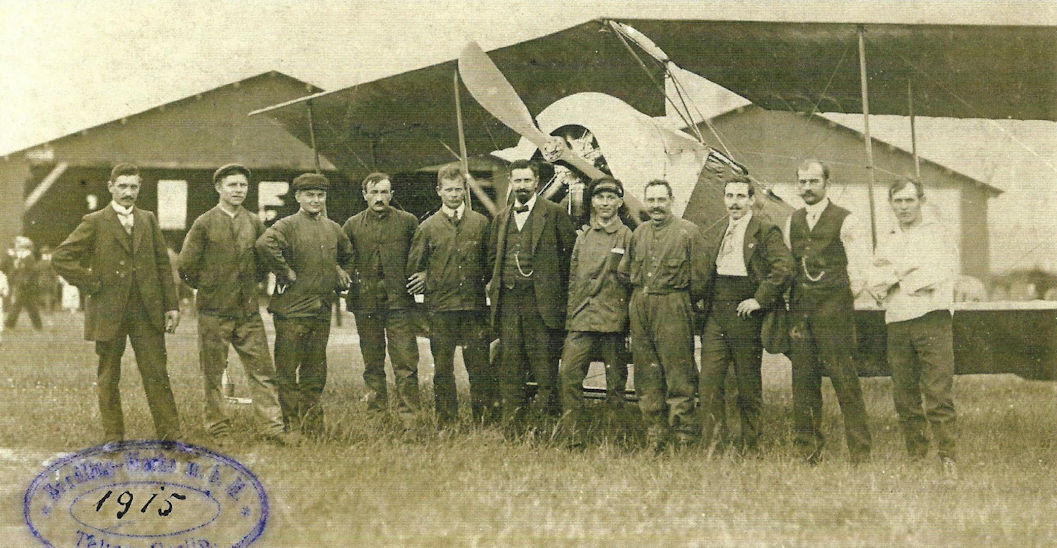
Union Arrow biplane with rotary engine with factory staff. (Peter M. Grosz collection, STDB)
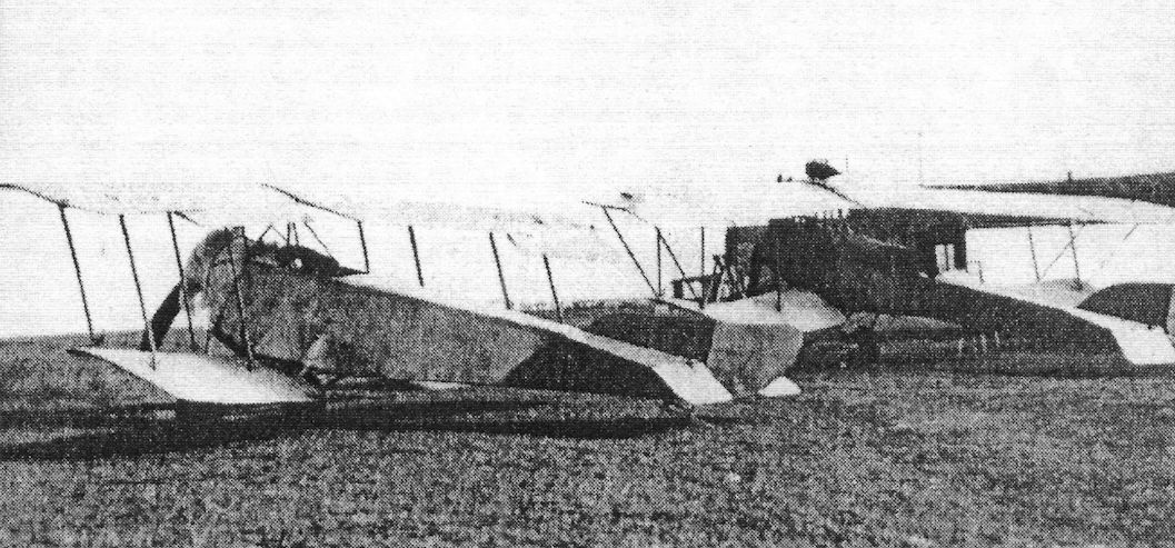
Union Arrow biplane with rotary engine on the factory airfield. (Peter M. Grosz collection, STDB)