R.Davies Airlines of the United States since 1914 (Putnam)
The First Steps
St Petersburg - Tampa
On 17 December, 1913, exactly ten years after Orville and Wilbur Wright’s now undisputed claim to have made the first power-driven, heavier-than-air, controlled flight, the city of St Petersburg, Florida, signed a contract with Thomas Benoist, aircraft manufacturer of St Louis, Missouri, for the operation of an airline. Two weeks previously, on 4 December, the company had been organized as the St Petersburg-Tampa Airboat Line by Paul E. Fansler, an electrical engineer, with the backing of city officials and businessmen. On 13 December, a contract was signed with the city of St Petersburg for a subsidy guarantee amounting to $50 per day during the month of January and $25 per day during February and March.
Much of the credit must go to Benoist. He had founded his company in St Louis in 1909 after making a fortune in the motorcar business, and his ambition was to demonstrate that aeroplanes were more than instruments of sport or machines of war; that they could be used as a practicable means of transport on a regular basis.
The conditions at St Petersburg were ideal for proving his point. The city was then a fast-growing community of about 8,000 people whose nearest retail and wholesale centre was Tampa, separated from it by Tampa Bay. To reach the local metropolis, the choice was a once-daily boat which took two hours, a 12-hr railway journey, or an arduous drive over dirt roads which took the greater part of a day. Benoist and Fansler had a captive market for their new product, air transport.
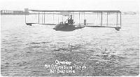
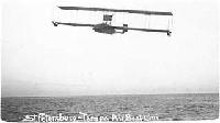
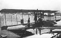
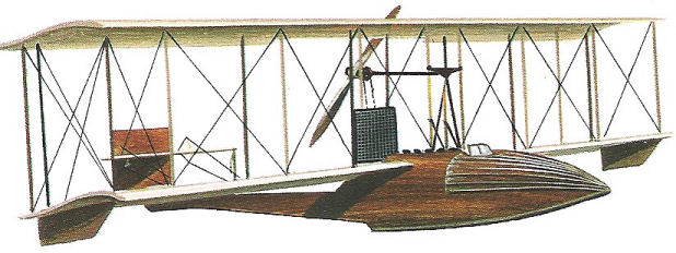
Benoist’s aircraft selected for the task was the Type XIV flying-boat, 26 ft long, weighing 1,400 Ib, and with a wing span of 36 ft. It was powered by a 75 hp Roberts six-cylinder engine driving a pusher propeller, flew at about 70 mph, and cost $4,150. The pilot was Tony Jannus, to whom the prospects of flying a regular schedule on the flimsy craft of plywood, spruce, and linen, was just as attractive as the racing and aerobatics which comprised the major proportion of aviation activity at that time.
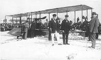
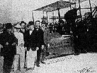
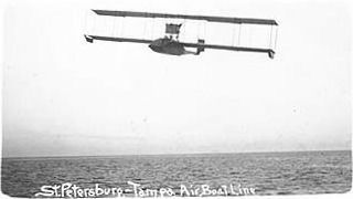
Regular flights started promptly at 10 a.m. on New Year’s Day, 1914, watched by most of the citizens of St Petersburg. The first passenger was ex-mayor A. C. Pheil, who paid $400 for the privilege. Subsequently passengers paid $5 for the single trip, and the same charge was made for 100 lb of freight. One interesting feature of this, the first regular airline tariff in history, was that an excess baggage charge of 5 cents per lb was made for passengers and baggage weighing more than 200 Ib, a remarkable similarity with the rates charged 50 years later.
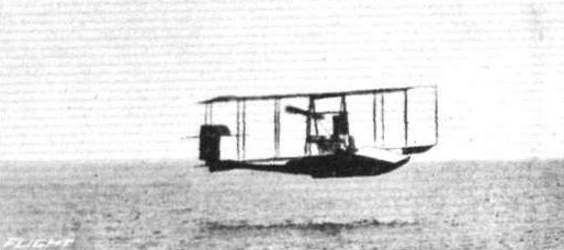
This first airline flight in the world took 23 min from the St Petersburg Yacht Basin to the mouth of the Hillsboro River at Tampa, a distance of 18 miles. With a following wind, the return journey took only 20 min, a feature of the service which repeated itself to the point where the local St Petersburg newspaper remarked on the way folks seemed anxious to get away from Tampa.
Settling down to fulfilling a regular timetable, with two round trips a day, the St Petersburg-Tampa Airboat Line was able to repay $360 of its municipal subsidy in January and paid its own way in February and March. Late in January, passenger demand was such that a second, larger, flyingboat was put into service, flown by Tony Jannus’ brother, Roger, who also undertook charter flights to local resorts. When the contract with the city expired on 31 March, 1914, the world’s first airline had carried 1,204 passengers without mishap. Bad weather and mechanical breakdowns forced cancellations on only eight days. Repairs to both aircraft cost only $100.
Operations were continued during April, but the Mexican war scare, combined with the wane of the tourist season, led to a fall in business, and the service was terminated. As a postscript to this early airline adventure, three of the main participants died before the start of the next airline - Benoist was killed, ironically, in a tramcar accident in St Louis in 1917; Tony Jannus disappeared over the Black Sea while training Russian pilots at the end of World War 1; and his brother Roger was killed in an aeroplane crash on the Western Front.
Показать полностью
Jane's All The World Aircraft 1913
BENOIST. Benoist Aircraft Co., 6628, Delmar Boulevard, St. Louis, Mo. (formerly Aeronautic Supply Co.
Model and date. 1912-13. 1913.
"Headless." Flying boat.
Tandem biplane.
Length............feet(m.) 22-1/3 (6.85) 27
Span..............feet(m.) 30 (9.15) 42-1/6 (12.80)
Area.........sq. feet(m?.) ... ...
Weight,total....lbs.(kgs.) ... 1004 (455)
useful...lbs.(kgs.) ... ...
Motor.................h.p. ... 75 Roberts
Speed, max.....m.p.h.(km.) 68 (110) ...
min.....m.p.h.(km.) 31 (50) ...
Endurance.............hrs. 3
Notes.--The boat of the flying boat is 23-5/6 feet long, by 2 feet 2? inches wide. Shipable wheels. See Aeronautics, January, 1913.
Показать полностью
Журнал Flight
Flight, February 28, 1914.
SOME AMERICAN FLYING BOATS.
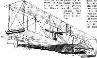
The Benoist Flying Boat.
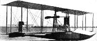
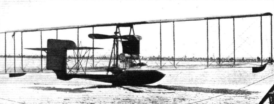
The Benoist flying boat represents an entirely different practice in flying boat design from that employed in the Curtiss and Burgess types. The respect in which the difference is mostly manifest is one of weight disposition, for whilst the two types mentioned above have the engine placed up between the main planes in order to raise the centre of gravity, the Benoist has the engine situated well down in the hull of the boat.
This, of course, gives this machine a comparatively low centre of gravity, and while this may, or may not, be a disadvantage in flight, it certainly renders the craft very stable on the water, and in modern machines, such as the Morane-Saulnier "Parasol," we have seen that a low e.g. is not prohibitive for good flying qualities.
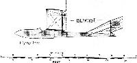
The boat itself, which has a length of 23 ft., is built up of double spruce planking over a skeleton of spruce longitudinals and ribs. In the nose of the boat the bottom is swept upwards in order to assist the boat in getting into its skimming position in the shortest possible time. A single step, 5 ins. high, occurs at a distance of 9 ft. 8 ins. from the nose of the boat, and from the step to the stern the hull slopes upwards as well as tapering to a vertical knife's edge carrying the rudder. The deck is swept downwards very abruptly from the occupants' seats to a point behind the rear plane struts, in order to provide sufficient clearance for the propeller. In front of the seats is a cowl, formed by a structure of spruce stringers covered with canvas, the purpose of which is to protect the occupants from wind and water spray.
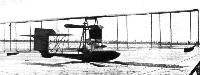
The method of mounting the engine is very interesting, as it serves at the same time to very materially strengthen the boat. Two strong spruce beams running parallel to each other practically the whole length of the boat serve as a support for the engine, and are spaced a distance apart sufficient to take the crank case arm bolts. The length of these beams is 17 ft., and in front of the step and under the engine they have a depth of 16 ins., and a thickness of two ins. From the step backwards they taper gradually to conform to the shape of the hull, and have been carefully proportioned for the various loads. Wherever possible, they have been lightened by hollowing them out. The engine drives through a chain transmission a single propeller situated behind the rear plane struts. The sprockets on the engine-shaft and propeller-shaft are of the same size, so that the gearing is 1 to 1. A tubular steel chain guard is fitted, and incorporated with it is a tubular radius rod which takes the pull of the chain, and provides easy adjustment of its length. This radius rod floats on ball-bearings at both ends. The tubular steel propeller-shaft is mounted between the main planes some 18 ins. below the trailing edge of the upper plane. Both ends of this shaft are carried on large combined radial and thrust bearings, which in turn are mounted on cast bronze retainers strongly supported to the central members of the cellule. Spruce struts tunning diagonally down to the leading edge of the lower plane, where that member joins the longerons of the boat, take the thrust reaction and preserve the rigidity of the rear bearing mounting. The propeller-shaft extension is fitted with a transverse pin, so that the engine can be started by the insertion of a starting handle. This operation is easily performed from either of the occupants' seats. The main planes, which are rectangular, as seen in plan, are both of equal span, and are built up in sections to facilitate transport. To the trailing edges of the outer sections of both planes are hinged ailerons of 8 ft. length, and a width of 1 ft. 8 ins. Mounted some distance above the deck of the boat is a fixed stabilising plane, to the trailing edges of which are hinged the two elevator flaps. The rudder is hinged to a post forming an extension of the stern post of the boat. A small portion of the rudder projects below the bottom of the boat, and serves as a water rudder when the machine is taxying on the water. The control levers are situated in front of the left hand seat (the seats are arranged side by side), and consist of a universally mounted lever operating the ailerons and the elevator.
Another lever actuates the rudder by a to-and-fro movement. The fuel tanks are placed in the hull on one side of the engine, and have a capacity for at least four hours' flight. All control cables are in duplicate, and are carried inside the hull, from which they emerge through a brass ferrule in the crown of the after deck. The general dimensions of the Benoist flying boat are :-
Span ... 35 ft.
Chord ... 5 ft.
Gap ... 6 ft.
Length ... 26 ft.
Length of hull 23 ft.
Weight, empty 1,190 lbs
Speed, fully loaded 64 m.p.h
Flight, August 20, 1915.
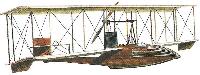
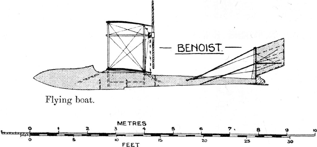
THE 1915 BENOIST FLYING BOATS.
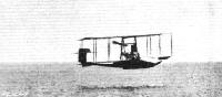
THE flying boats manufactured by the Benoist Aeroplane Co. of Chicago, Ill., are among the few - at one time the only - craft of this type in which the motor is mounted in the hull. A low centre of gravity is thus obtained, and the craft is thereby made as seaworthy as is possible, and good stability in the water is as essential as good stability in the air. It is generally accepted, however, that a low centre of gravity in an aeroplane is not always a desirable factor where stability in the air is concerned, so it will be seen that it is a somewhat difficult proposition to so design the craft that the advantage of one condition is not to be outweighed by the disadvantage of the other. That the designer of the Benoist flying boat succeeded in surmounting this difficulty is borne out by the fact that the first machines to be built at once made a name for themselves on the score of good stability, both in the water and in the air. Many notable performances are to their credit, especially the first regular daily passenger air service between St. Petersburg and Tampa, Fla., a distance of about 20 miles across Old Tampa Bay, which was started on January 1st last year.
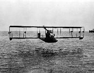
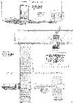
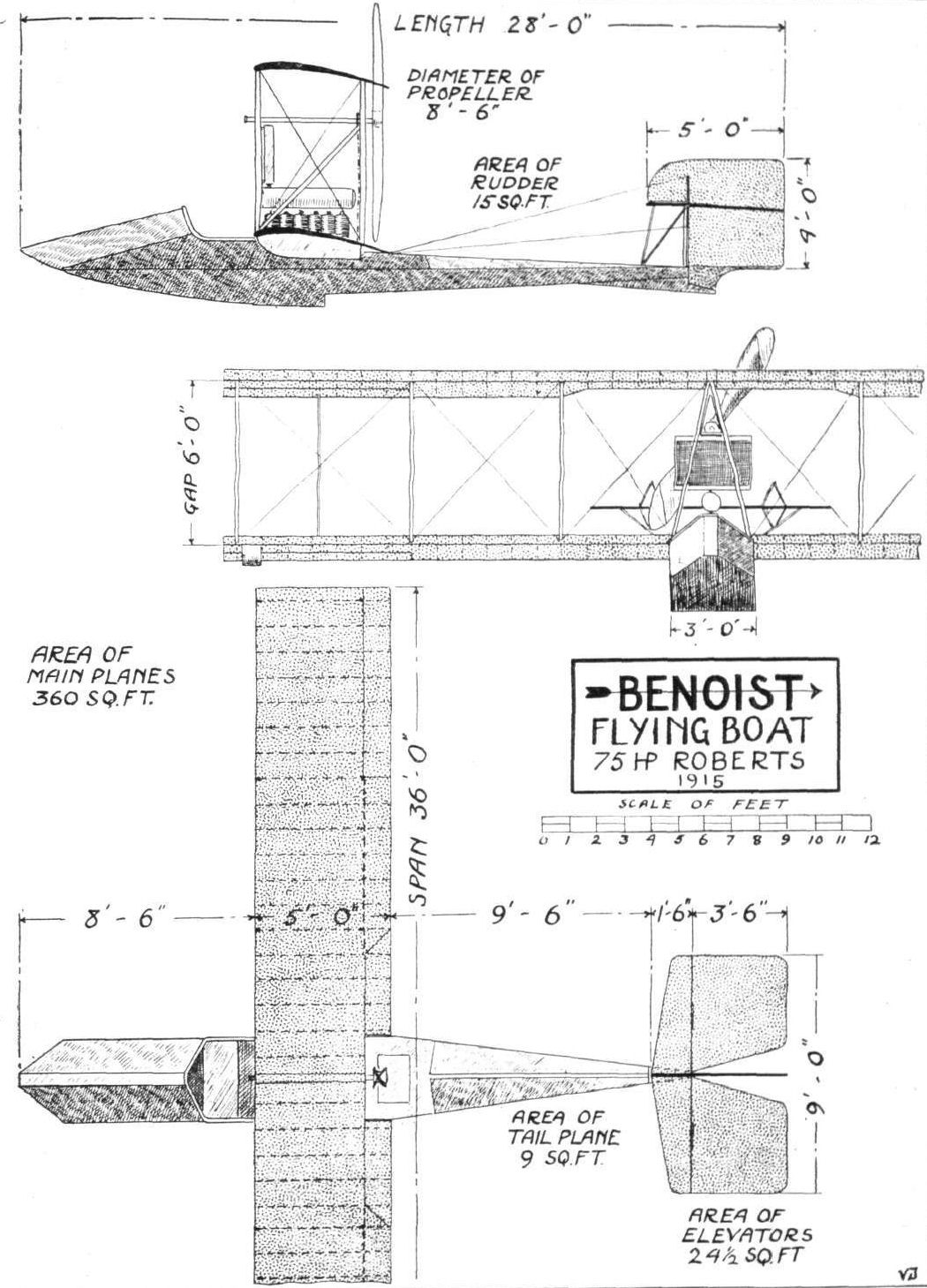
The 1915 Benoist machines differ from the previous models only in a few details, the most important of which is the location of the engine. This is still placed in the hull, but instead of being mounted on the bottom, as before, it is now half way up in the hull, so that it is almost level with the lower plane. Here is, therefore, a compromise between the engine-in-the-hull type and the engine-between-planes type, and the arrangement appears to have given very good results. Another modification is to be found in the boat, which now has a roomier cockpit, and in place of the canvas hood over the latter there is an inverted V-shaped deck. The boat is of the single step type, very wide and deep forward, tapering to a point at the stern. The bottom is perfectly flat laterally throughout, and curves up from the step to the bow. Aft of the planes the boat has an inverted V deck, which has the advantage of allowing the water to flow off easily in the event of the waves breaking over the hull. This, and the ample freeboard forward, renders the boat exceptionally seaworthy. The step is 5 ins. deep, and is situated some distance behind the centre of pressure, 10 ft. 6 ins. from the bow. From the nose to the step the hull is built up of two layers of 1/4 in. spruce planks, having a layer of canvas set in between, whilst aft of the step it is constructed of single 3/8 in. spruce planks, which are reinforced inside at the seams with spruce battens. Spruce planking 3/8 in. thick, laid in the same manner, forms the sides, and the upper portions are covered with mahogany. The framework consists of spruce longitudinals and ribs, and the boat is divided into five watertight compartments. Six coats of Valspar outside and three coats inside are put on the hull, which has a total length of 24 ft. 6 ins., and he maximum beam is 3 ft. Pilot and passenger are seated side by side immediately in front of the main planes, and he engine is mounted on strong bearers between the main spars of the lower plane. Of 8 ft. 6 ins. in diameter, the propeller, mounted high up behind the main planes, is driven at engine speed by means of a roller chain-running in a tubular guard, while the pull of the chain is taken by a hollow radius rod. Mounted some two feet below the top plane the hollow steel propeller shaft extends forward as far as the cockpit, where provision is made for the engagement of a crank for starting the engine. A pair of spruce struts take thrust reaction, and at the same time contribute towards the support of the rear propeller shaft mounting.
Top and bottom planes are of equal span, 36 ft., and have a chord of 5 ft. and a gap of 6 ft. They are also each in two sections, being divided midway where they are attached to the boat in the case of the lower plane, and to the innermost interplane struts in the case of the top sections. The aforementioned interplane struts, of which there are two pairs, are arranged A fashion, and it is to the apex of the A the top plane sections are attached.
This arrangement is not only simple but forms a strong support for both planes and propeller mounting. There are three pairs of vertical struts on either side of the boat separating top and bottom planes. The planes themselves are constructed on more or less orthodox lines, the foremost of the two main spars for each plane forming the leading edge, the other being situated one foot from the trailing edge. Hinged to each outer extremity of the rear spars of both top and bottom planes is an aileron measuring 7 ft. by 1 ft, all four being interconnected, so that when the pair on one side moves up the pair on the other moves down. Under each extremity of the lower plane is mounted a float for supporting the wing tips on the water when the machine is taxying. The tail consists of a small stabilising surface of high aspect ratio, to the trailing edge of which are hinged two large elevator flaps with a partly balanced rudder in between. The lower portion of the latter is of wood and projects into the water, and thus acts as a water rudder when taxying. The whole tail is supported about two feet above the boat by a stout ash strut extending from the stern and by a series of bracing tubes. The control is either of the Benoist or Deperdussin type, the former consisting of two levers, the right-hand one operating the ailerons and elevators, and the left-hand one the rudder.
If required, arrangements can be made for mounting the engine up between the planes, the main characteristics remaining as before.
The specifications of Model "A," 75 h.p. two-seater, are :- Span, 36 ft.; chord, 5 ft.; gap, 6 ft.; supporting area, 360 sq. ft.; overall length, 28 ft.; weight, empty, 1,180 lbs.; useful load, 650 lbs. Another model, "B," a 100 h.p. for two or more passengers, is also manufactured. This machine is practically the same as model "A," with the following principal modifications :- Span, 51 ft. 6 ins.; supporting area, 497 sq. ft.; weight, empty, 1,390 lbs.; useful load, 800 lbs. The chord and gap are the same as in Model "A," and the engine can also be mounted between the planes if desired, in which case another seat is provided behind that of the pilot, where the engine would be if located in the hull. The latter is similar to that of the other model, and has a beam of 3 ft. 6 ins., and a length of 24 ft.
Показать полностью