F.Manson British Bomber Since 1914 (Putnam)
Tarrant Tabor
Not only was the Tarrant Tabor six-engine triplane almost fifty per cent heavier than the Handley Page V/1500, but it was expected to be able to carry a ton greater bomb load about thirty per cent further. It was the product of highly competent engineers and an imaginative concept.
W G Tarrant Ltd was a well-known woodworking contractor at Byfleet, Surrey, which had supplied countless structural components to other aircraft manufacturers and had patented a method of constructing wing spars featuring wooden lattice webs. In 1917 W G Tarrant took this a stage further, securing a patent for lattice-braced circular girders for use in large aircraft fuselages. He was to be joined by Marcel Lobelle from the nearby company of Martinsyde, and by W H Barling from the Royal Aircraft Factory.
Together they produced the design of a very large four-engine biplane towards the end of 1917, intending that it should be powered by four 600hp Siddeley Tigers, arranged in tandem pairs at midgap. It soon became evident, however, that the Tiger would not be ready in the timespan of the aircraft and, in order to maintain a comparable power/weight ratio, Tarrant elected to fit six 450hp Napier Lions instead, at the same time adding an upper, third wing with the same dimensions and structure as those of the bottom wing, transferring the support for what became the central wing's large overhang to the top wing, the diagonal support struts now being stressed in tension instead of compression.
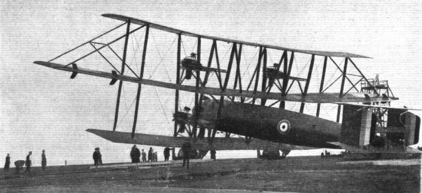
The additional Lion tractor engines were mounted directly above the lower pairs, the pairs of interplane struts to which the nacelles were braced being raked outwards towards their apices; additional diagonal centresection struts passed from the upper wing, through the central wing to meet on the aircraft's centreline below the fuselage and on the lower wing, thereby forming, in effect, the section of a huge Warren truss of great strength. It is assumed that the bomb load, amounting to the equivalent of about twenty 230 lb HE RL bombs, would have been carried under the lower wing centresection, for the wing structure would thus have distributed the load to all the wings without compromising the cylindrical fuselage structure.
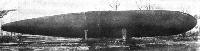
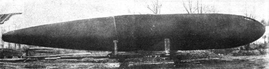
The fuselage was a finely-streamlined, cigar-shaped structure which carried a biplane tail unit, comprising two tailplanes, the lower of which incorporated a horn-balanced elevator, and the upper a trimming surface operated by handwheel in the pilot's cockpit. A second elevator was mounted in the tailplane gap.
The undercarriage comprised two suitably massive structures, each carrying three five-foot-diameter main wheels on their own common axle. With each wheel assembly being attached by struts directly beneath the engine mounting interplane struts, the landing loads were distributed directly between the three wings and, at the same time provided an uninterrupted wheel track of no less than 31ft 5in.
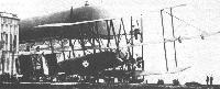
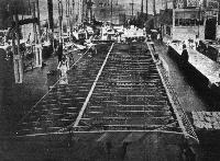
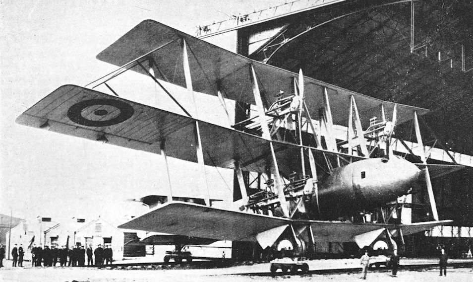
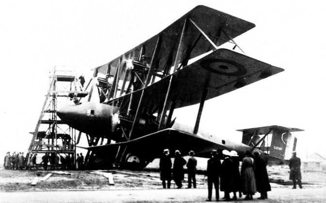
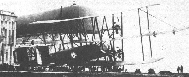
Such was the great overall height of the Tabor (37ft 3in compared, for instance, to 20ft 8in of the Bristol Braemar triplane bomber) that Tarrant arranged for its final assembly to be undertaken in the huge balloon shed at Farnborough, the finished aircraft being moved in and out sideways on a specially-constructed pair of railway tracks.
Prior to its first scheduled flight, the Tabor was examined and tunnel-tested by both the Royal Aircraft Establishment and the National Physical Laboratory. Unfortunately the reports by the two authorities conflicted, the RAE suggesting that the aircraft was excessively tail-heavy, and it is understood that representations were made to add 1,000 lb of lead ballast in the nose, although this proposal was put forward by a third party. Tarrant disagreed with this recommendation and, on the instructions of Maj-Gen Henry Robert Moore Brooke-Popham, the Deputy Assistant QMG (later Air Chief Marshal Sir Robert, GCVO, KCB, CMG, DSO, AFC, RAF), the investigation reports were not to be divulged. It is therefore not known whether Tarrant and the pilots, detailed to make the first flight, were aware that the ballast had been added on that occasion.
The aircraft was made ready for flight on 26 May 1919, the pilots being Capt F G Dunn AFC, RAF and Capt P T Rawlings DSC, accompanied by four crewmen. After completing the lengthy process of starting the six engines, which required the use of a large gantry, Dunn carried out a number of trial taxying runs before starting his take-off. After lifting the tail, he opened up the two upper engines, and the huge triplane was seen to tip on to its nose; the undercarriage collapsed, the aircraft reared up and came to rest tail-up, the nose being crushed. Both Dunn and Rawlings died shortly afterwards in hospital.
The subsequent investigation concluded that the direct cause of the accident was the sudden onset of increased thrust from the top pair of engines (whose thrust line was about 28 feet from the ground), which caused the aircraft to pitch on to its nose. It seems likely that, had the pilots been aware of the heavy ballast added in the nose, they would have been much less inclined to apply so much extra power from the upper engines, bearing in mind that the overall weight of the aircraft was relatively light (without bombs and with only limited fuel).
Thus ended a courageous attempt to produce a very large bomber whose capabilities seemed likely to represent a marked advance beyond those of the V/1500. Whether such a radical attempt was justified, especially as there were important differences of opinion among the best specialist technical agencies in the country as to the stability of the aeroplane, it is impossible to decide. Certainly it was clearly not economical to further develop the Tabor as a six-engine, passenger-carrying commercial airliner, even if Tarrant had felt inclined to do so. Yet one is perhaps left with the impression that, with the top wing discarded, together with the two upper engines, a biplane might well have succeeded on the power produced by, say, four Rolls-Royce Condor engines.
Type: Six-engine, six-crew, three-bay triplane long-range heavy bomber.
Manufacturer: W G Tarrant Ltd, Byfleet, Surrey; aircraft assembled at the RAE, Farnborough.
Powerplant: Six 450hp Napier Lion twelve-cylinder, water-cooled, broad-arrow in-line engine (four tractor and two pusher) driving two-blade propellers.
Structure: All-wood throughout with Tarrant lattice-webbed circular fuselage frames, covered overall with 2mm or 4mm ply.
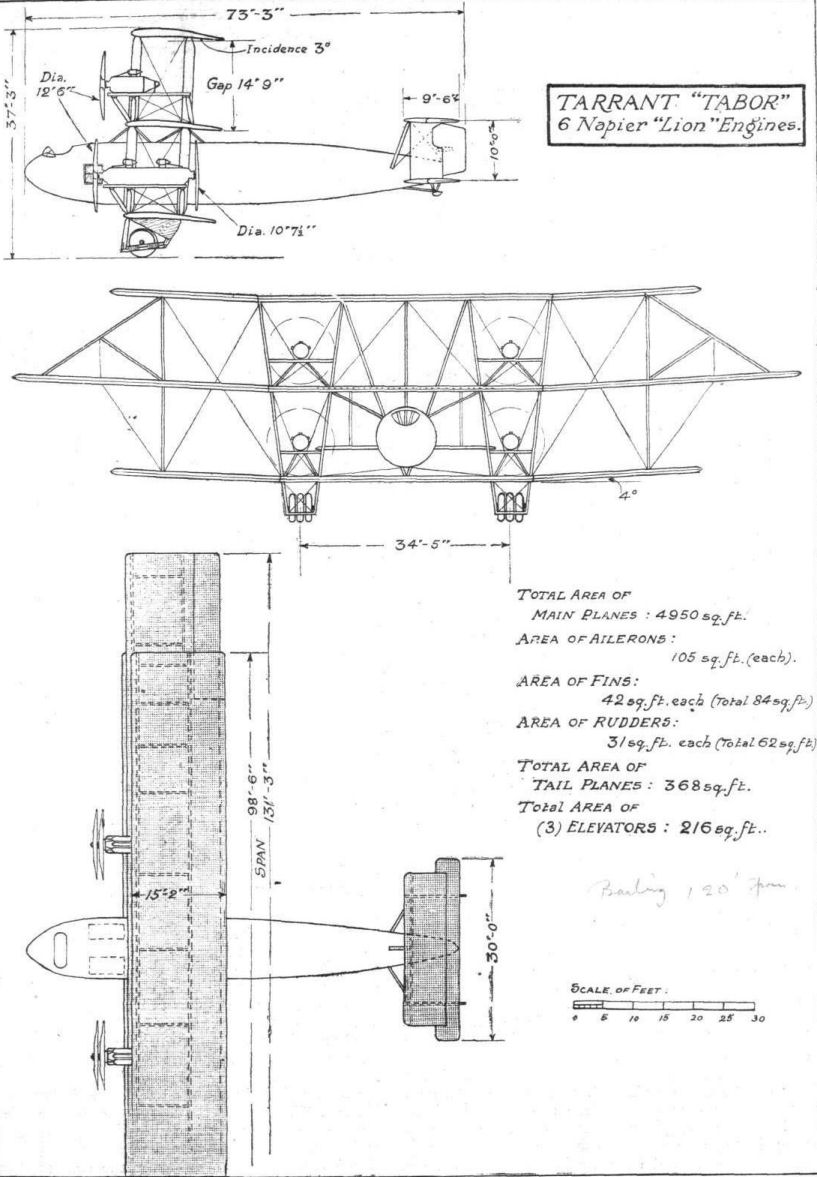
Dimensions: Span, 131ft 3in; length, 73ft 2in; height, 37ft 3in; wing area, 4,950 sq ft.
Weights: Tare, 24,750 lb; all-up (with 5,130 lb war load), 44,672 lb.
Performance (estimated): Max speed, over 110 mph; climb to 10,000ft, 33 min 30 sec; service ceiling, 13,000 ft; endurance, 12 hr.
Armament: No gun armament on prototype; bomb load equivalent to about twenty 230 lb HE RL bombs.
Prototype: One, F1765 (second aircraft, F1766, cancelled); F1765 crashed on take-off for first flight on 26 May 1919 at Farnborough, killing the two pilots, Capt F G Dunn and Capt P T Rawlings. No production.
Показать полностью
J.Bruce British Aeroplanes 1914-1918 (Putnam)
Tarrant Tabor
ALTHOUGH designed and built under a war-time contract and with war-time requirements in view, A the Tarrant Tabor was not completed until 1919. It was an aircraft in the same category as the Handley Page V/1500, for it was intended to bomb Berlin from bases in England.
The manufacturers of the Tabor were a firm of building contractors noted for the production of wooden buildings, and some of the plant was turned over to the manufacture of aircraft components after the outbreak of war. For their first attempt to produce an aircraft of their own, the Tarrant company could hardly have built anything more ambitious than the Tabor.
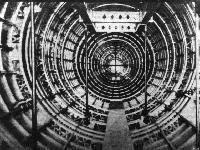
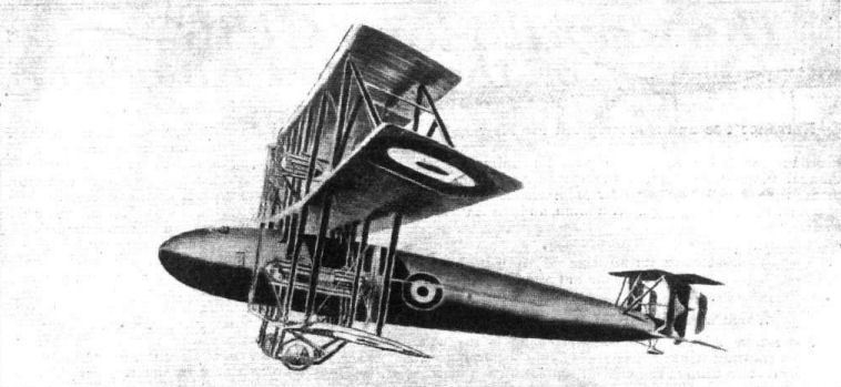
It was a vast triplane which rivalled the German Riesenflugzeuge in sheer size. The central mainplane was considerably larger than the top and bottom wings, and it alone was fitted with ailerons. The fuselage was a monocoque structure of circular cross-section and good aerodynamic form; it was the largest monocoque fuselage (as distinct from flying boat hull) which had been made in Britain up to that time.
There was a biplane tail-unit with twin fins and horn-balanced rudders. There were two elevators: one was a horn-balanced surface attached to the lower tailplane; the other was midway between the tailplanes. A third movable surface was attached to the upper tailplane, but was a trimming surface only, actuated by means of a handwheel in the cockpit.
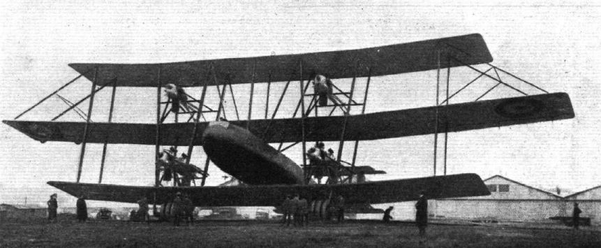
The Tabor was designed to have four Siddeley Tiger engines which were expected to develop 600 h.p. each. The Tiger fell short of expectations, however, and none were available when the airframe was nearing completion. The nearest equivalent total horse-power could be provided by using six Napier Lions, and that alternative was adopted. Four of the engines were mounted in two tandem pairs between the middle and bottom wings; the tractor engines drove two-bladed airscrews, the pushers four-bladers of smaller diameter. The other two engines were mounted as tractor units between the top and middle wings, and their thrust line must have been quite 27 feet above ground level.
The undercarriage was a massive affair, each unit of which had three wheels mounted close together on a common axle.
The estimated performance of the Tabor was quite good, and its load included sufficient fuel for eight hours’ flying in normal cruising conditions or, if only four engines were used, for twelve hours at an average speed of 91 1/2 m.p.h.
The aircraft was built in close collaboration with the Royal Aircraft Establishment and was assembled in the balloon shed at Farnborough, whence it had to be brought out sideways on special trucks running on rails.
On May 26th, 1919, the Tabor was prepared for its first flight. The first pilot was Captain F. G. Dunn, A.F.C., and the second pilot was Captain P. T. Rawlings, D.S.C. After taxying trials, Dunn increased speed, lifted the tail from the ground, and opened up the two upper engines. The Tabor immediately turned over on to its nose, which collapsed, and finished up resting on the leading edges of the wings with fuselage vertical. Dunn and Rawlings sustained fatal injuries.
At the inquest Mr Tarrant disclosed that his consulting engineers had disagreed with the R.A.E. calculations based on tests of a model of the Tabor, and had thought that the aircraft would be very tail-heavy. Mr Tarrant had wanted independent confirmation of the test results from the National Physical Laboratory but, after further discussions with R.A.E. officials, had been convinced that his consulting engineers were wrong. Perhaps it was a residual doubt that had led to the carrying of about half a ton of lead shot in the nose as ballast, though that alone could hardly have caused the disaster. It seems probable that the sudden thrust exerted by the high top engines may have sufficed to push the machine on to its nose.
SPECIFICATION
Manufacturers: NT G. Tarrant, Ltd., Byfleet, Surrey.
Power: Six 450 h.p. Napier Lion.
Dimensions: Span: middle 131 ft 3 in.; top and bottom 98 ft 5 in. Length: 73 ft 2 in. Height: 37 ft 3 in. Chord: 15 ft 2 in. Gap: 14 ft 9 in. (both). Dihedral: 4. Incidence: 3. Span of tail: 30 ft. Wheel track: 34 ft 5 in. between centres. Airscrew diameter: tractors 12 ft 6 in.; pushers 10 ft 7 1/4 in.
Areas: Wings: 4,950 sq ft. Ailerons: each 105 sq ft, total 210 sq ft. Tailplanes: each 184 sq ft, total 368 sq ft. Elevators: upper 54 sq ft, lower 81 sq ft. Area of top trimming elevator: 81 sq ft. Fins: each 42 sq ft. Rudders: each 31 sq ft.
Weights: Empty: 24,750 lb. Military load: 5,130 lb. Crew: 1,080 lb. Fuel and oil: 13,712 lb. Loaded: 44,672 lb.
Estimated Performance: Maximum speed: over 110 m.p.h. Climb to 5,000 ft: 10 min 30 sec; to 10,000 ft:
33 min 30 sec; to 13,000 ft: just over 60 min. Ceiling: 13,000 ft. Endurance: normal, 8 hours; maximum, 12 hours.
Tankage: Petrol: 1,600 gallons. Oil: 92 gallons.
Armament: No details were released, but the weight of bombs and bomb gear was 4,650 lb, which represented a load equivalent to about forty 112-lb bombs.
Serial Numbers: F.1765-F.1766. The second machine was not built.
Показать полностью
Журнал Flight
Flight, May 8, 1919.
THE TARRANT GIANT TRIPLANE
AT last authentic particulars of the Tarrant triplane, regarding which rumour has been busy for some time, are available for publication. Guarded references to this interesting machine have been made from time to time, but these have been mostly of such a nature as to stimulate curiosity without satisfying it with facts and figures. A few days ago the veil surrounding the details of the machine was removed, and our representatives had an opportunity of examining the machine in every detail.
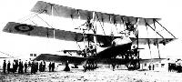
The general lay-out of the Tarrant triplane will be gathered from the accompanying illustrations. The chief characteristic is perhaps the triplane arrangement with top and bottom planes of equal span and a middle plane of considerably greater span than that of the other two. Next comes the power plant, which consists of six Napier "Lion" engines, four of which are mounted on the bottom plane, the other two being placed between the middle and the top plane, and driving tractor screws. The fuselage is of the monocoque type, and is of a very good stream-line form. Originally the machine was designed for long-distance bombing, but it will now be converted into a passenger carrier.
All the woodwork has been done at the Tarrant Works at Byfleet, but a good proportion of the metal work has been carried out at the Royal Aircraft Establishment at Tarnborough. The most important feature of the Tarrant "Tabor" as regards construction is the adoption of the Warren type of girder to wood construction. In metal, this girder has long been employed, but practical difficulties, chiefly in regard to terminal attachments, has hitherto delayed its employment where wood is the material.
Without actually seeing the machine, the quotation of dimensions is apt to convey only a vague sense of her great size, but when it is mentioned that the span of the middle plane is a little over 130 ft., and the height from the ground to the top plane is 37 ft. 3 ins., some idea can be formed oà the magnitude of the task of constructing this machine. The weight of the Tarrant "Tabor," as the machine is named, is approximately 45,000 lbs., of which 9,000 lbs. is available for passengers and cargo, while 10,000 lbs. are taken up by the fuel for the six engines, which develop an aggregate of 2,700 to 3,000 h.p. With all engines running at full throttle the speed is estimated at 110 m.p.h., giving a range of about 900 miles, while at the "cruising speed" (the most economical speed) the range is calculated to be about 1,200 miles. This is with 10,000 lbs. of petrol on board and carrying 9,000 lbs. of passengers and cargo. If fewer passengers are carried and the tankage increased, the range can be very considerably extended.
When the machine was inspected a few days ago, she was nearly ready for flight, and barring unforeseen accidents she should be ready for testing very soon.
Mr. W. G. Tarrant, of Byfleet, Surrey, is to be congratulated upon his courage in tackling such a costly experiment in the interests of the development of the large commercial aeroplane of the future, which cannot fail to benefit the cause of aviation not only in this country, but throughout the world. He has associated with him a number of specialists, of whom we mention only a few. Capt. E. T. Rawlings, D.S.C., general manager of the firm, will be remembered as being one of the crew of the Handley Page bomber which flew from London to Constantinople, dropping bombs with good effect on the latter city. Capt. T. M. Wilson, of the Technical Department of the Air Ministry, was lent to the firm by that Department, and has now left the Ministry and joined Mr. Tarrant permanently. It was to a very great extent due to Capt. Wilson that the machine was turned into a practical proposition. The pilot of the Tarrant triplane will be Capt. F. G. Dunn, A.F.C., who will be remembered by most readers of FLIGHT as one of the Grahame-White pilots at Hendon before the War. Finally it should be mentioned that Majors Turner and Grinstead, of the R.A.E., have rendered valuable assistance in the construction and erection of the machine.
Time does not permit of a more lengthy description of the Tarrant triplane this week, but we hope to publish an illustrated detailed description at an early date.
Flight, May 15, 1919.
THE TARRANT GIANT TRIPLANE, THE "TABOR"
AFTER a thorough examination of the Tarrant "Tabor" triplane, a brief reference to which was made in FLIGHT last week, it is a matter of some difficulty to decide which of its features possess the greater novelty - the aerodynamic design or the constructional principles adopted. Both present many unusual aspects. Probably on balance the constructional side will be found to be the more interesting.
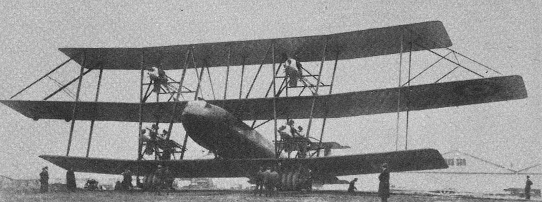
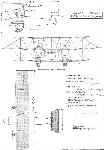
Aerodynamically the most striking features of the Tarrant "Tabor," apart from the great size of the machine, are the overhanging middle plane, with top and bottom planes of shorter span, and the disposition of the various thrust lines in relation to the centre of resistance. Dealing with these various features in the order given, the enormous size of the Tarrant "Tabor" impresses one instantly on seeing the machine. This impression is caused, not so much, perhaps, by the span, although 131 ft. 3 ins. is admittedly a great spread of wings, as by the height of the top plane. When standing close up to the machine, the 37 ft. 3 ins., which constitutes the distance from the ground line to the centre section of the top plane, looks a formidable height, and the two Napier engines, which develop some 450 h.p., each look almost ridiculously small, perched between the middle and top planes.
As regards the triplane arrangement, the unusual extension of the middle plane attracts attention at once. It might be noted here that only the middle plane carries ailerons, and in view of the extra load thus imposed upon the extensions of this plane the method employed for bracing the extensions may perhaps, be open to criticism, a compression strut of great length taking the upward load. It is usually found that the middle plane in a triplane combination is very much less efficient than the other two, and probably the same would apply to the wing flaps of a middle plane. An extenuating circumstance is certainly formed by the fact that the upper and lower planes are of shorter span, and hence would not, presumably, affect the efficiency to the same extent. Since, however, there are generally disturbances in the neighbourhood of the wing tips, it may be that the ailerons will be affected. However, these are purely theoretical speculations, and only practical experiments can furnish conclusive proof.
Then there is the disposition of the various thrust lines, in other words, as direct drive is used in all instances, the placing of the six engines. From the front elevation of the G.A. drawings it will be seen that not only are all the engines placed far out on the wings, much farther than is usually found on twin or multi-engined machines, but the two upper engines are placed very high. Probably, with all engines running, any discrepancy between centre of resistance and centre of thrust will not be great, but one imagines that in case one of the top engines cuts out, it might be necessary to shut off one of the engines on the opposite bottom plane to equalize matters. Or, looking at it in another way, if the thrust is right with the two top engines idle, forming, as it were, a reserve of engine power, then one would think that the switching on of these engines would raise the resultant centre of thrust, necessitating a considerable amount of tail plane trimming. When discussed with some of the Tarrant specialists recently, this point was more or less admitted, but it was then pointed out to us that any such tendency to bring the tail up would be counterbalanced by the down draught from the top plane. This is probably correct, and therefore the effects of the widely distributed engine placing may be smaller than one is apt to imagine at first sight.
Reference has already been made to the unusual bracing of the middle plane extensions. Equally out of the ordinary is the inter-plane strutting of the machine. The body, it will be noticed, does not rest on the bottom plane, but is supported from it by Vee struts, which continue through the middle and up to the top plane. The length of spar between the points of attachment to the upper plane of these Vee struts is halved by a vertical strut coming out of the top of the fuselage. The struts on each side of the engines diverge, counting from the bottom towards the top plane. The object of this arrangement, we understand, is to divide the top plane into "free lengths" of spars corresponding with the loading at any point; in other words, the greater the loading the shorter the free length of spar.
From the outer engine struts to the wing tips all the planes are given a dihedral angle of 4#, while the centre sections are straight. The machine is an orthogonal triplane, having its interplane struts at right angles to the chord lines (in side elevation), which virtually amounts to a slight negative stagger.
The tail of the Tarrant triplane is of the biplane form, but has, in addition to the two elevators hinged to the two fixed biplane tail planes, a third elevator placed as the middle plane in a triplane. This elevator and the bottom one are both connected to the control column, while the top elevator is operated by a separate trimming-gear, placed in the side of the pilot's cockpit. This elevator takes the place of the ordinary moveable tail plane, and provides, it will be seen, for trimming of the machine by virtually altering the camber of the top tail plane rather than by altering the incidence of the usual trimming flat tail plane.
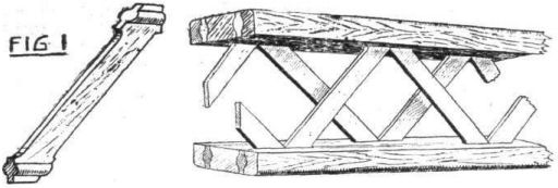
Constructionally the predominating feature of the Tarrant "Tabor" is the adaptation of the Warren girder principle to wood construction. In bridge and similar work the Warren girder has long been extensively employed, but for aeroplane construction its adoption has been delayed for various practical reasons. Whereas, in riveted metal girder structures the attachment of the braces to the flanges does not present any great difficulties, it is another matter where wood is concerned. Not that wood does not have a good tensile strength, but the difficulty lies in providing good terminal connections, in other words, in securing the braces to the flanges of the beams. The first really practical way of doing this with woodwork that we have yet seen is that evolved by Mr. W. G. Tarrant, who has patented the method.
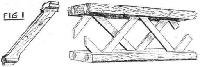
As one of the accompanying sketches (Fig. 1) will indicate, the Tarrant method consists in building up spars, etc., of flanges built up in three vertical laminations, having grooves cut in them lengthwise. The webs, or more correctly the braces, consist of two Warren girders displaced relative to one another, the braces being beaded to fit the grooves, and distance pieces glued in between the brace ends.
It will be seen that this form of construction, quite apart from its merits from the point of view of weight for strength, has the very great advantage that quite small pieces of wood may be utilised, a fact which is of the greatest importance at a time when wood in such lengths as would be required for a machine of this size would be almost unobtainable. The very fact that such small pieces are being used is furthermore, in itself, a good factor of safety, since no defects are likely to remain undiscovered. The same principle of construction has been applied to the spars of the tail planes, to the circular formers of the fuselage and to the longerons for a certain portion of their length. As regards the weight-strength ratio of wing spars made on this principle, we are informed that the designers of the Tarrant machine have found that such construction results in a saving of about 10 per cent, in weight for the same strength compared with a box section spar, provided it is assumed that for practical reasons it is not possible to make the walls of the box section thinner than 3/16 in., which assumption is probably quite justified. It would, therefore, appear that Mr. Tarrant has discovered a method of construction which has very much to recommend it; at any rate, for the very large aeroplanes of the future, assuming that wood will remain the material employed for most of the component parts of the machine for some years to come. That metal will ultimately supplant it is not unlikely.
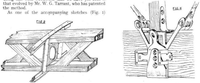
The wing ribs are of standard type, and are made in spruce. It might be mentioned, incidentally, that the wing section is that known as R.A.F. 15. The ribs are attached to the spars in such a manner as to transfer the shear stress from the rib to the spars. How this is accomplished will be understood from an inspection of one of the accompanying sketches (Fig. 2). A three-ply tongue passes between top and bottom spar flanges, extending a short distance on each side of the spar. Tacked and screwed to this tongue are on each side two vertical strips tacked to the rib webs, and having between them a packing piece of the same thickness as the rib web.
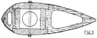
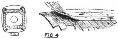
While on the subject of the wing ribs, mention may be made of the internal compression struts for the drag bracing. In some machines these members are in the form of box ribs, others employing square section solid wood struts, while still another way is to use steel tubes. In the Tarrant "Tabor" the compression struts are of a built-up square section as shown in the sketch Fig. 3. A similar construction is employed for the interplane struts, with the addition, of course, of a fairing. This takes the form of two-ply wood of similar construction to that used in the covering of the fuselage. This ply-wood work is made on moulds of the required shape, the layers being put on so as to get the grain of the two laminations running approximately at right angles to one another (Fig. 4). It is put on in 1 1/4 in. wide strips, varying in thickness from 1 mm. to 3 mm., according to the work it has to do. A section of one of the interplane struts is shown in Fig. 5. In Fig. 6 is shown a typical spar fitting.
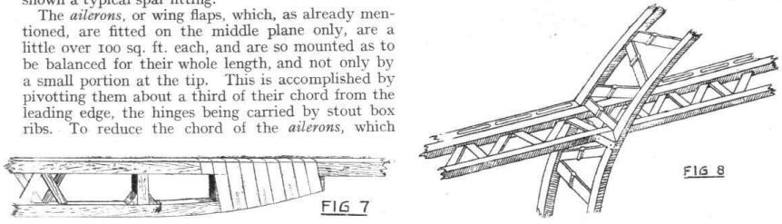
The ailerons, or wing flaps, which, as already mentioned, are fitted on the middle plane only, are a little over 100 sq. ft. each, and are so mounted as to be balanced for their whole length, and not only by a small portion at the tip. This is accomplished by pivotting them about a third of their chord from the leading edge, the hinges being carried by stout box ribs. To reduce the chord of the ailerons, which would have been excessive had they been hinged to the main rear spar, there is a false spar overhung on the box ribs from the rear main spar. The chord of the ailerons is 3 ft. 9 ins., with the hinge line 9 ins. from the leading edge.
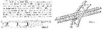
The fuselage is of the monocoque type, built up of circular formers or rings, constructed on the same general principle as that already dealt with in describing the wing spars, and of longerons similarly constructed as regards a certain portion of their length. The whole is then covered with a skin of two-ply wood, put on in two thicknesses of narrow strips, crossing one another approximately at right angles. The workmanship of the body construction is excellent, and the monocoque form has, among others, the very great advantage of giving much more space inside, there being no bracing wires, etc., to divide the space up into a series of "birdcages." The importance of this for passenger carrying will be obvious. It should be mentioned that it is only the main formers which are built up of Warren trusses. Between these main formers are lighter single formers. From the side elevation of the general arrangement drawings, it will be noticed that the fuselage is parallel for a certain portion of its length. The longerons in this portion are Warren girders, while towards the stern they are tapered down to single members, as shown in Fig. 7. The method of attaching the Warren girder longerons to the formers of that construction, without resorting to cutting either, is the subject of another illustration (Fig. 8). The flanges of the former pass outside the flanges of the longeron, and to bring the outer longeron flange flush with the covering a packing piece is employed as shown in the sketch. The sketch is, we think, self-explanatory.
The two pilots, who are placed in the nose of the fuselage, sit side by side, and all controls are duplicated. The ailerons and middle and bottom elevators are operated by hand wheels, and the rudders by foot bars in the usual way. For trimming the tail there is on each side a wheel, one for each pilot, geared to the top elevator.
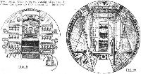
Immediately behind the pilots' seats there is a transverse partition, forming the engineer's dash board, on which all the various engine controls - and they are necessarily numerous where six engines are fitted - are mounted in readily accessible positions. The sketch Fig. 9 shows this dashboard, and a portion of the pilot's cockpit, seen through the door communicating with the engine room.
Provision is made for the engineer to climb out on to the wings, through a hatchway, thus gaining access to any of the engines that may require attention.
Most of the petrol is carried in the fuselage, in tanks mounted on the sides and top, so as to leave the centre of the body clear. The manner of placing the tanks will be seen in Fig. 10.
The tail unit is of fairly orthodox design, and does not call for any special comment. The only detail in which it differs from standard practice is, as already mentioned, that trimming is not effected by altering the angle of incidence of the fixed tail planes, but by altering the angle of the top elevator. There is no adjustment of the tail planes during flight, but the bottom tail plane is so mounted as to allow of slight adjustment when the machine is on the ground.
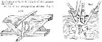
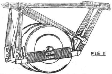
The undercarriage consists of two separate units, each placed vertically below the engines. The sketch, Fig. 11, will give an idea of one of these units. Each unit consists of what, for want of a better term, we shall call two truncated Vees, across the lower members of which is slung the very substantial axle carrying three wheels inside the Vees. The size of the Palmer cord wheels, by the way, is 1,500 by 300. At its outer ends the axle is carried in a bearing mounted on a stout longitudinal member, which is free to travel up and down, but is guided as regards lateral and longitudinal movement. This beam is sprung by rubber cord wrapped around it and the fixed bottom member of the "truncated Vee." The sketch will explain the principle. Needless to say, front and rear panels of each chassis unit are braced to take lateral loads.
As shown in the G.A. drawings, the engines are placed as follows :- Two on the middle plane, one on each side, driving tractor screws, and four in two tandem sets on the lower plane, driving tractors and pushers respectively. The engines are all Napiers of about 450 h.p. each. The tractor airscrews are two-bladed, and of 12 ft. 6 ins. diameter, while the pusher screws are four-bladed, and have a diameter of 10 ft. 7 1/4 ins. The engines can be started from the cockpit by the Maybach system. A vaporiser is placed near the engines, and connected up to a hand pump in the fuselage. To start the engines the exhaust valves can be lifted, petrol or ether vapour pumped into the cylinders, the valves closed, and the mixture exploded by a spark from a hand magneto on the engineer's switchboard. It might be mentioned that in order to facilitate starting, provision has been made for heating the cooling water. Later on, we understand, it is intended to fit an electric starter, as soon, in fact, as a reliable one has been evolved.
As regards the ignition system, each engine is fitted with two magnetos. The earth wires for each magneto are carried to the engineers' control board, on which is a double switch for each engine. Each of these switches controls the two magnetos on one engine. From these switches leads are taken to a master switch capable of earthing the 12 magnetos simultaneously. This master switch is placed in the pilot's cockpit, within easy reach of either pilot. On the engineer's control board are mounted two starting magnetos, one serving three engines via a distributor switch. That is to say, the one starting magneto serves all three starboard engines, the other serving all three port engines.
The cooling system is so arranged that each engine has its independent system. A pump draws the cool water from the bottom of the radiator through a pipe into the engine. After being forced through all the channels of the water jackets, etc., the water passes through a pipe into the bottom of the water tank, which is mounted above the engine, and is in shunt with the system. The radiators are placed under the engines, and are provided with shutters for regulating the cooling.
In conclusion, it might be mentioned that the weight, fully loaded, of the Tarrant "Tabor" is about 45,000 lb., of which 19,000 lb. is useful load. The amount of petrol carried is 10,000 lb., leaving 9,000 lb. for passengers and/or cargo. This 10,000 lb. of petrol is sufficient for a flight of 900 miles at maximum speed, while at the cruising speed the range of the machine is estimated at 1,200 miles, with the 10,000 lb. of petrol. If fewer passengers are carried, and the weight made up with fuel, this range can, of course, be still further increased. The ceiling of the machine has been estimated at 13,000 ft., and the estimated climb is as follows :- 5,000 ft. in 10 1/2 mins., 10,000 ft. in 33 1/2 min., 13,000 ft. in just over one hour.
The following is a table of leading dimensions and weights of the Tarrant "Tabor" :-
Engines, six 500-h.p. Napier "Lion."
Span: middle plane, 131 ft. 3 in.; top and bottom plane, 98 ft. 5 in.
Total surface of wings, 4,950 sq. ft.
Overall height, 37 ft. 3 in.
Overall length, 73 ft. 2 in.
Body, round streamline, maximum diameter 11 ft.
Gap: top and middle planes, 14 ft. 9 in.; middle and bottom planes, 14 ft, 9 in.
Chord, 15 ft. 2 in.
Dihedral, 4 deg. on all planes.
Area of ailerons, on middle plane only, 105 sq. ft. each = 210 sq. ft. total.
Area of fin, 42 sq. ft. each, total 84 sq. ft.
Area of rudders, 31 sq. ft. each, total 62 sq. ft.
Area of tail planes, 184 sq. ft. each, total 368 sq. ft.
Area of elevators, 81 sq. ft. each, total 162 sq. ft.
Area of inter-elevator, 54 sq. ft.
Span of tail planes, 30 ft.
Gap of tail planes, 10 ft.
Wings are set at 3 deg. to the body.
Top tail plane at - 2 deg. to the body.
Bottom tail plane at o deg. to the body.
Weights
Lbs.
Top plane 1,903
Bottom plane 2,691
Middle plane 1.833
Interplane struts 2,543
External bracing wires 608
Total 9,578
Tail planes 334
Elevators 117
Fins 98
Rudders 40
Total 589
Fuselage (including
bomb girders) 3,590
Chassis 2,582
Tail skid 60
Controls 501
Total 6,733
Engines, propellers, radiators
and water, etc. 7,200
Engine accessories 650
Petrol and tanks
(1,600 galls.) 12,662
Oil and tanks, etc.
(92 galls.) 1,050
Crew (five) 1,080
W.T 100
Guns and ammunition 380
Bombs and gears 4,650
Total 44,672
Mr. Tarrant, on the recent occason when Press representatives were permitted to view the machine, stated that he wished to express his thanks to the Royal Aircraft Establishment at Farnborough, without whose very valuable and willing assistance the problems of erecting and trueing up the machine would have been rendered even more difficult than had been the case, and in this direction he should like to mention Majors Turner and Grinstead, of the R.A.E., who have both given their unstinted help in the many problems that, in the very nature of the job, have kept cropping up. Of those directly associated with Mr. Tarrant it would be impossible to mention more than a few: Capt. E. T. Rawhngs, D.S.C., who is general manager of the firm, will be remembered by all FLIGHT readers as having taken part in the famous flight in a Handley Page from London to Constantinople, bombing the Turkish capital with excellent effect. Captain T. M. Wilson, of the Technical Department of the Air Ministry, was originally lent to Mr. Tarrant, but has now joined the firm. It was to a large extent due to Captain Wilson that the machine was turned into the flying proposition it is now.
Finally, it should be pointed out that the man who will pilot the machine is Captain F. G. Dunn, A.F.C., who will be remembered by our readers from the days before the War, when he was one of the Grahame-White pilots at Hendon, forming one of the batch who joined up with the air forces immediately on the outbreak of hostilities, and who numbered among them such pilots as, to mention only a few, Strange, Carr, Lillywhite, Noel, Howarth, Pashley, and Manton.
Flight, May 29, 1919.
THE TARRANT TRIPLANE
AFTER months of painstaking work, and having solved an endless succession of constructional problems those responsible for the large Tarrant "Tabor" triplane, have suddenly seen the results of their labours annihilated in the course of a few minutes by the accident which occurred on Monday last. Not only is the beautiful structure, for beautiful it was from a constructional point of view, whatever may have been one's opinion of the design, reduced to matchwood, but at least one of the men who had worked on the machine from the time of its inception has succumbed to the injuries sustained in the accident, while a second man, the pilot, is lying in a critical condition. We are sure that all readers of FLIGHT will join us in expressing our sympathy with the relatives of Capt. Rawlings, D.S.C., who died shortly after the accident, and with Capt. Dunn, A.F.C., who is still, at the time of writing, in a very critical condition. To Mr. W. G. Tarrant we also express our sincerest sympathy in the misfortune that has overtaken the machine into which, with rare courage, he had put so much thought and treasure. We understand that so certain is Mr. Tarrant that his principle is right that another machine will be put in hand immediately, incorporating, it may be taken, many alterations in design, but utilising the same constructional principle.
With regard to the accident itself, it is difficult to be certain of the exact cause, but it would appear that the machine was travelling along the ground at high speed with the four lower engines running, and that, in order to get sufficient speed to rise, the pilot opened out the two top engines, which had up till then been throttled down, with the result that the extra thrust, applied so far above the centre of resistance of the machine, brought the tail up. The momentum thus imparted to the machine, especially that of the two top engines, was, at any rate momentarily, too great to be overcome by the tail planes and elevators, and the result was that the machine turned on to her nose. It is quite conceivable that had the machine been in the air the momentary pitching could have been corrected by trimming the tail, but on the ground there was no time in which to do this before the machine was over. By keeping cool to the last, the horror of a fire was avoided by someone - probably one of the pilots, as there was a master switch in their cockpit - switching off the engines, otherwise the disaster might have been far greater than was the case.
In addition to the two pilots, there were on board a t the time of the accident the following :- Capt. T. M. Wilson, who, as the machine turned over, was flung into the rear part of the fuselage and sustained a broken leg; Lieut. Adams, engineer-in-charge, who accompanied Capt. Rawlings on the famous flight to Constantinople in a Handley-Page; Mr. Grosert, of the R.A.E.; two mechanics.
The injuries to the crew, with the exceptions of those sustained by the pilots, are not thought to be serious.
Показать полностью