
Книги
Putnam
J.Bruce
British Aeroplanes 1914-1918
659
J.Bruce - British Aeroplanes 1914-1918 /Putnam/
A.D. Scout, the Sparrow
THE A.D. Scout, or Sparrow, was designed in 1915 by Harris Booth and was intended to be an anti-Zeppelin fighter. The armament was to have been a Davis recoilless quick-firing gun, a weapon in which the Admiralty were then interested.
The Sparrow was a single-engined pusher biplane of unusual appearance. Sketches of a wind-tunnel model depict a two-bay biplane of fairly large gap, with the nacelle attached to the upper wing: it appeared that the spars of the wing were attached to the underside of the upper longerons of the nacelle. An enormously tall undercarriage was necessary, but the track of the wheels was absurdly narrow. Presumably it was hoped that the widely separated twin tail-skids would provide sufficient ground stability.
The tail-booms were parallel in plan and elevation, and supported a single tailplane of great span. There were two fins and rudders.
The nacelle was an ugly, angular affair which had obviously been designed round the gun: the weapon was mounted on the floor of the nacelle, and the barrel protruded two feet in front. The engine was an 80 h.p. Gnome rotary mounted at the rear of the nacelle. The pilot sat well forward of the wings and must have had an excellent all-round view from his cockpit.
Four A.D. Scouts were ordered - two from the Blackburn company and two from Hewlett & Blondeau. It is uncertain whether all were built, but at least one was completed and was flown at Chingford. The Sparrow turned out to be considerably overweight, and on test it proved to be unsatisfactory and tricky to fly. It was quickly abandoned.
SPECIFICATION
Manufacturing Contractors: The Blackburn Aeroplane and Motor Co., Olympia, Leeds, Yorkshire. Hewlett & Blondeau, Ltd., Leagrave, Bedfordshire.
Power: 80 h.p. Gnome.
Approximate Dimensions: (Derived from drawings of a wind-tunnel model.) Span: upper 32 ft 4 in., lower 33 ft 5 in. Length: 22 ft 9 in., 24 ft 9 in. over gun. Height: 10 ft 3 in. Chord: 4 ft 6 in. Gap: 5 ft 9 1/2 in. Stagger: 1 ft 7 in. Dihedral: 3 30'. Span of tail: 21 ft. Wheel track: 2 ft 7 in. Track of tail-skids: 11 ft 2 in. Airscrew diameter: 9 ft.
Serial Numbers: 1452-1453: ordered from Hewlett & Blondeau under Contract No. 38552/15. 1536-1537: ordered from Blackburn.
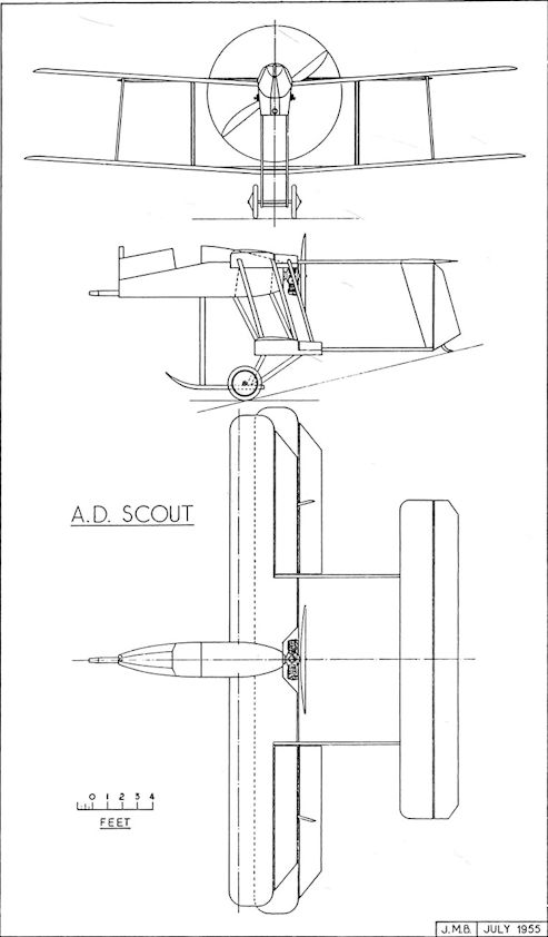
A.D. Sparrow. This drawing is based on scale drawings for a wind-tunnel model.
A.D. Seaplane Type 1000
BRITISH experiments in dropping torpedoes from aircraft began in 1913, and had from their inception the blessing of Captain Murray F. Sueter (later Rear-Admiral Sir Murray Sueter, C.B.), the Director of the Air Department of the Admiralty.
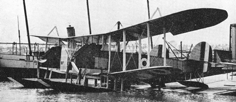
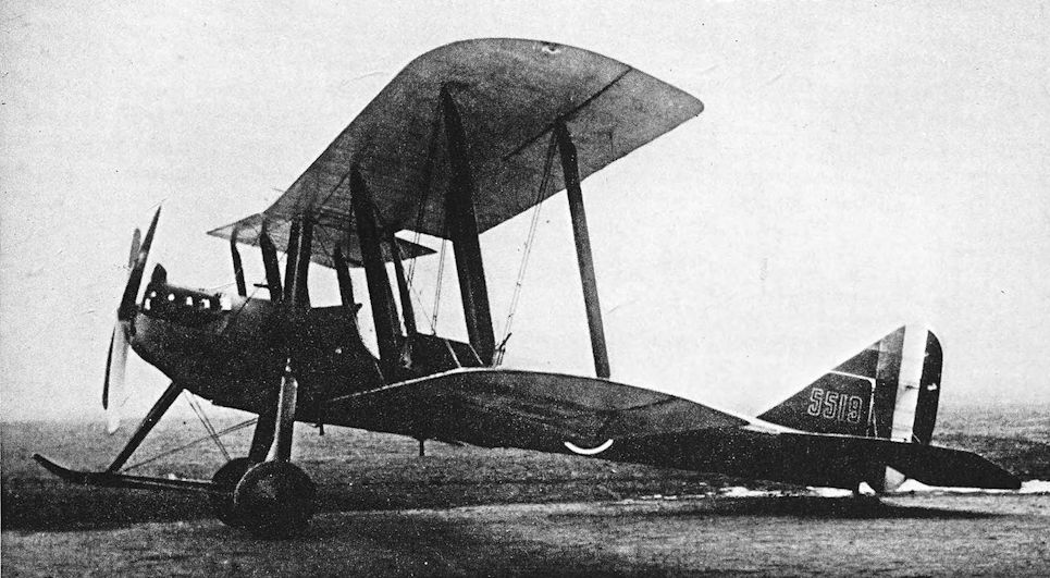
In 1914, Harris Booth of the Air Department designed an enormous twin-float seaplane which was intended to be used as a bomber or torpedo-carrier. When it appeared it was the largest aeroplane of any type which had been built in Britain. It was powered by three 310 h.p. Sunbeam engines, two of which were installed as tractor units at the forward ends of the twin fuselages. The third engine was mounted at the rear of the central control cabin (which was much too imposing a structure to be called a mere nacelle) and drove a pusher airscrew. All three engines had cowlings which were remarkably ugly and cumbersome. The control cabin looked uncommonly like a domestic greenhouse, and was little better streamlined. The machine was to have had a crew of five.
The serial number 1000 was provisionally allotted for the type which, in accordance with the Admiralty practice of the time, thereupon became known as the Type 1000.
It is believed that seven examples were ordered, but only one, No. 1358, was completed. Construction was undertaken by J. Samuel White & Co., Ltd., of Cowes, the makers of the Wight seaplanes; and consequently the A.D. 1000 has been wrongly described as a Wight type.
It was not a success. Its clumsy appearance rightly betokened excessive structural weight, and its floats were too flimsy: they were unable to withstand even a slight sea.
The A.D. Type 1000 was abandoned, and probably ended its days at Felixstowe. It was there in the summer of 1916. In his book From Sea to Sky, Air Chief Marshal Sir Arthur Longmore wrote of it:
“Another boat of weird design had been delivered some time before; it looked like a floating conservatory with two floats and a double fuselage and three engines; but it was evidently not very popular for it had stayed in its shed ever since.”
SPECIFICATION
Manufacturers: J. Samuel White & Co., Ltd., Cowes, Isle of Wight.
Power: Three 310 h.p. Sunbeam.
Dimensions: Span: 115 ft.
Serial Numbers: 1000: ordered under Contract No. C.P.01516/14. 1355-1360. No. 1000, Nos. 1355-1357 and Nos. 1359-1360 were not delivered.
BRITISH experiments in dropping torpedoes from aircraft began in 1913, and had from their inception the blessing of Captain Murray F. Sueter (later Rear-Admiral Sir Murray Sueter, C.B.), the Director of the Air Department of the Admiralty.
In 1914, Harris Booth of the Air Department designed an enormous twin-float seaplane which was intended to be used as a bomber or torpedo-carrier. When it appeared it was the largest aeroplane of any type which had been built in Britain. It was powered by three 310 h.p. Sunbeam engines, two of which were installed as tractor units at the forward ends of the twin fuselages. The third engine was mounted at the rear of the central control cabin (which was much too imposing a structure to be called a mere nacelle) and drove a pusher airscrew. All three engines had cowlings which were remarkably ugly and cumbersome. The control cabin looked uncommonly like a domestic greenhouse, and was little better streamlined. The machine was to have had a crew of five.
The serial number 1000 was provisionally allotted for the type which, in accordance with the Admiralty practice of the time, thereupon became known as the Type 1000.
It is believed that seven examples were ordered, but only one, No. 1358, was completed. Construction was undertaken by J. Samuel White & Co., Ltd., of Cowes, the makers of the Wight seaplanes; and consequently the A.D. 1000 has been wrongly described as a Wight type.
It was not a success. Its clumsy appearance rightly betokened excessive structural weight, and its floats were too flimsy: they were unable to withstand even a slight sea.
The A.D. Type 1000 was abandoned, and probably ended its days at Felixstowe. It was there in the summer of 1916. In his book From Sea to Sky, Air Chief Marshal Sir Arthur Longmore wrote of it:
“Another boat of weird design had been delivered some time before; it looked like a floating conservatory with two floats and a double fuselage and three engines; but it was evidently not very popular for it had stayed in its shed ever since.”
SPECIFICATION
Manufacturers: J. Samuel White & Co., Ltd., Cowes, Isle of Wight.
Power: Three 310 h.p. Sunbeam.
Dimensions: Span: 115 ft.
Serial Numbers: 1000: ordered under Contract No. C.P.01516/14. 1355-1360. No. 1000, Nos. 1355-1357 and Nos. 1359-1360 were not delivered.
A.D.1000
A.D. Navyplane
THE Navyplane was a two-seat pusher biplane floatplane sponsored by the Air Department of the Admiralty in 1916, and intended for reconnaissance and bombing duties. It was designed by Harold Bolas of the Air Department in collaboration with Messrs R. J. Mitchell and Richardson of the Supermarine Aviation Works, Ltd., to which company the construction of the machine was entrusted.
Eight weeks after the drawings were received by the Supermarine company the Navyplane was completed, an achievement which brought the manufacturers a letter of appreciation from Commodore Murray F. Sueter. Serial numbers were allotted for seven machines but only one was built. The Navyplane’s test flights were carried out in August, 1916, by Lieutenant-Commander John Seddon.
Structurally the Navyplane was a two-bay biplane with the tail unit supported on four tail-booms, and its most remarkable feature was its monocoque nacelle which, complete with seats and floor-bearers, weighed no more than 80 lb. The nacelle had a sectional glass screen which was led round the nose from the forward windscreen to a point under the pilot’s seat; this gave the crew a good forward and downward view. The Navyplane carried wireless, and the observer had a Lewis gun on a special flexible mounting. The nacelle was mounted mid-way between the wings. The wings themselves were made in three parts and only the outer portions were rigged with dihedral. The tailplane was attached to the upper tail-booms and was of the inverted camber type.
The main floats were pontoon structures and were connected horizontally by only one cross-bar. Each of the twin tail-floats had a water-rudder.
The Navyplane’s original power-plant was a new type of radial engine, the 150 h.p. Smith Static. The design of this engine was brought to England in January, 1915, by an American, John W. Smith, who succeeded in interesting the Admiralty in it almost immediately. The Smith Static was a ten-cylinder single-row radial engine which had offset connecting rods bearing alternately on the cranks of a two-throw crankshaft. The engine must have been reasonably successful. It was tested on the bench and in the air to the satisfaction of the Admiralty. A contract for its production was given to Messrs Heenan & Froude, but only a few were delivered before the Armistice.
The Smith engine was installed quite neatly in the A.D. Navyplane but was later replaced by a 150 h.p. A.R.I. rotary engine. The reason for the change is uncertain, but difficulty may have been experienced with the cooling of the radial. With the A.R.I engine the Navyplane was tested in May, 1917, but with no military load and no observer the performance was very poor.
SPECIFICATION
Manufacturers: The Supermarine Aviation Works Ltd., Woolston, Southampton.
Power: 150 h.p. Smith Static radial engine; later, 150 h.p. A.R.I rotary engine.
Dimensions: Span: 36 ft. Length: 27 ft 9 in. Height: 12 ft 9 in. Chord: 5 ft. Gap: 6 ft 6 in. Stagger: nil. Span of tail: 15 ft 6 in. Airscrew diameter: 8 ft 10 in.
Areas: Wings: 364 sq ft.
Weights (lb) and Performance:
Engine Smith Static A.R.I
Date of Trial Report - 15 May, ’9'7
Weight empty 2,100 2,042
Military load - nil
Crew - 180
Fuel and oil - 328
Weight loaded 3,102 2,550
Maximum speed (m.p.h.) at 2,000 ft 75 64-5
Climb to 2,000 ft - 30 min
Service ceiling (feet) - 1,300
Endurance (hours) 6 6
Armament: One Lewis machine-gun on a movable mounting for the observer.
Serial Numbers: 9095-9096. (9096 was not built.) N.1070-N.1074: cancelled.

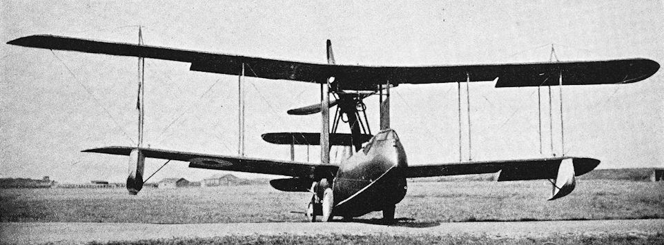
Three-quarter Rear View of a "Pusher" Seaplane, built by the Supermarine Co.
A.D. Navyplane No. 9095 with the Smith Static engine.
A.D. Navyplane No. 9095 with the Smith Static engine.

A.D. Navyplane No. 9095 with the 150 h.p. A.R.I engine.
A.D. Flying Boat
THIS two-seat patrol flying boat was designed by the Air Department of the Admiralty. The design work was carried out in the autumn of 1915 under Harris Booth, and the hull was one of the first to be designed by Lieutenant Linton Hope.
Construction of the first hull was undertaken by May, Harden & May, and the completion of the aircraft was entrusted to Pemberton-Billing, Ltd. The detail design was carried out by Harold Bolas, Harold Yendall and Clifford W. Tinson of the Air Department, who went to the Pemberton-Billing works specially for the purpose.
Two prototypes, numbered 1412 and 1413, were flying in 1916. These machines differed slightly in detail: the first had a semi-enclosed bow cockpit, whilst the second had an open bow cockpit and a slightly deeper radiator.
At first, considerable trouble was experienced, for the machine porpoised badly on the water. The Admiralty sought the advice of the scientists who were associated with the experimental work carried out at the Froude National Tank of the National Physical Laboratory. Tests were carried out in August, 1916, at Southampton but were discontinued before the trouble was eradicated. At one time the step was moved two feet farther aft at the suggestion of Squadron Commander J. L. Travers, but that did not cure the machine of porpoising.
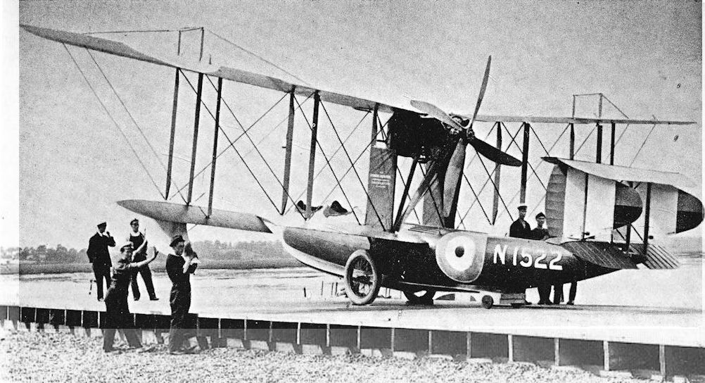
A solution must have been found at a later stage, for production was undertaken on a small scale; the production machines were generally similar to No. 1413. The engine for which the original installation was designed was the 150 h.p. Sunbeam Nubian, but both prototypes and production A.D. Flying Boats were built with Hispano-Suiza engines. The standard power-plant was the 200 h.p. geared Hispano-Suiza, but N.1525 at least had the 150 h.p. direct-drive engine of the same make.
The A.D. Flying Boat was flown in February, 1917, by Squadron Commander Travers, Flight-Lieutenant Goodwin and Flight-Lieutenant Barlow, when some excellent performances were recorded. One A.D. Boat rode out a 38 m.p.h. gale for seven hours in an open harbour without damage and shipped only 120 lb of water.
The hull was a wooden monocoque of good form and sturdy construction; it was claimed that the A.D. Flying Boats were stronger, weight for weight, than the larger F boats. One was subjected to rather drastic tests to prove the strength of the hull: it successfully withstood thirty-six successive heavy landings in which it was deliberately stalled at some 10-12 feet above the water. An unusual feature of the design was the provision for the fitting of wheels to enable the machine to be flown from the deck of a carrier vessel; after take-off the wheels were jettisoned.
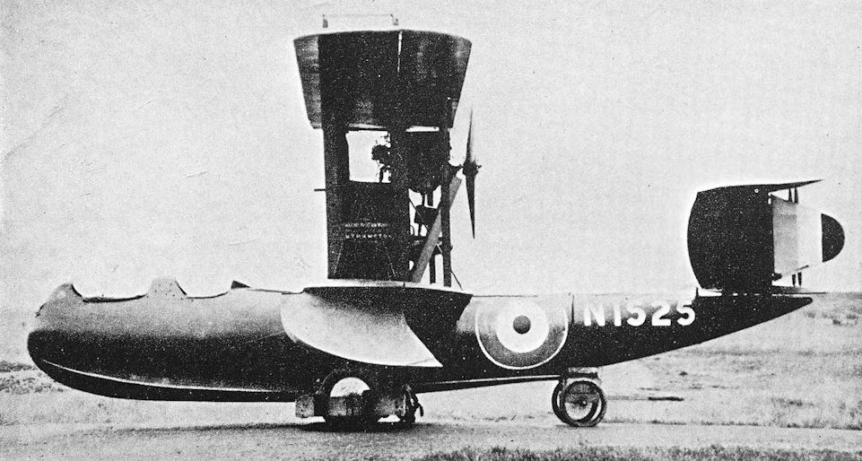
The upper tailplane was of inverted aerofoil section and was mounted at a slightly negative angle of incidence, for it was thought that in the event of engine failure the reversed camber would prevent the tail from dropping. The lower tailplane, which was awash when the flying boat was taxying in heavy seas, was covered with plywood and was a watertight structure. The wings could be folded, presumably to conserve space when carried on board ship, but contrary to contemporary practice they folded forwards.
One of the later production A.D. Flying Boats, N.1719, was used in experiments with hydrovanes. Two were fitted: one was just aft of the pilot’s cockpit, the other about six feet aft of the trailing edge of the wing. Each hydrovane was some 18 inches below the keel of the hull.
In September, 1918, an A.D. Flying Boat was tested with the 200 h.p. Wolseley Python engine. The installation was experimental, and performance was not good.
The A.D. Flying Boats did not distinguish themselves in any operational way during the war, but with the coming of peace they provided the basis for the successful Supermarine Channel type, which, powered by the 160 h.p. Beardmore or 230 h.p. Siddeley Puma, was one of the earliest commercial flying boats to go into service and was used in many parts of the world.
SPECIFICATION
Manufacturers: Pemberton-Billing, Ltd. (later the Supermarine Aviation Works, Ltd.), Woolston, Southampton.
Power: 150 h.p. Hispano-Suiza; 200 h.p. Hispano-Suiza; 200 h.p. Wolseley Python.
Dimensions: Span: upper 50 ft 3 15/16 in., lower 39 ft 7 1/4 in. Length: 30 ft 7 in. Height: 13 ft 1 in. Chord: 5 ft 6 in. Gap: 7 ft. Stagger: nil. Dihedral: mainplanes 4°, lower tailplane 2° 30'. Incidence: mainplanes 30, upper tailplane -0° 30', lower tailplane + 5°. Span of tail: upper 9 ft 10 in., lower 8 ft 4 in.
Areas: Wings: 479 sq ft. Tailplanes: total 60 sq ft. Fins and rudders: total 40 sq ft.
Weights (lb) and Performance:
Engine 150 h.p.
Hispano-Suiza 200 h.p. Hispano-Suiza 200 h.p. Wolseley Python
No. of Trial Report 8A - N.M.214
Date of Trial Report July 3, 1917 July 12, 1917 September 21, 1918
Type of airscrew used on trial A.D.645 A.B.6622
Weight empty 2,400 2,508 2,360
Military load 216 206 176
Crew 360 360 360
Fuel and oil 351 493 492
Weight loaded 3.327 3,567 3,388
Maximum speed (m.p.h.) at
2,000 ft 91 100 87-5
6,500 ft 83 99 87
10,000 ft - 90 -
m. s. m. s. m. s.
Climb to
2,000 ft 6 00 3 00 5 35
6,500 ft 26 00 14 00 23 50
10,000 ft - - 30 00 55 00
Service ceiling (feet) 7.500 11,000 8,800
Endurance (hours) 5 4 1/2 3 1/2| at 3,000 ft
Armament: One Lewis machine-gun on movable mounting in bow cockpit. A small bomb load could be carried.
Production: Serial numbers indicate that two prototypes and at least twenty-seven production machines were built. On April ist, 1918, when the Air Department handed over to the newly-formed Royal Air Force, eighteen A.D. Flying Boats were in service, nine were under construction or on order, and one had been written off.
Serial Numbers: 1412-1413: ordered under Contract No. C.P. 109611/15. N. 1290-N.1299: ordered under Contract No. A.S.1449. N.1291-N.1299 were not built. N.1520-N.1529: ordered under Contract No. A.S.5388/17. N.1710-N.1719: ordered under Contract No. A.S.20798. N.2450-N.2455: ordered under Contract No. A.S. 18936.
Notes on Individual Machines: N. 1525 had the 150 h.p. Hispano-Suiza engine. N.1719 was experimentally fitted with hydrovanes below the hull.
Costs:
Airframe, including hull but without engine, instruments and gun £2,853 8s.
Airframe without hull £1,925 0s.
200 h.p. Hispano-Suiza engine £1,004 0s.
THIS two-seat patrol flying boat was designed by the Air Department of the Admiralty. The design work was carried out in the autumn of 1915 under Harris Booth, and the hull was one of the first to be designed by Lieutenant Linton Hope.
Construction of the first hull was undertaken by May, Harden & May, and the completion of the aircraft was entrusted to Pemberton-Billing, Ltd. The detail design was carried out by Harold Bolas, Harold Yendall and Clifford W. Tinson of the Air Department, who went to the Pemberton-Billing works specially for the purpose.
Two prototypes, numbered 1412 and 1413, were flying in 1916. These machines differed slightly in detail: the first had a semi-enclosed bow cockpit, whilst the second had an open bow cockpit and a slightly deeper radiator.
At first, considerable trouble was experienced, for the machine porpoised badly on the water. The Admiralty sought the advice of the scientists who were associated with the experimental work carried out at the Froude National Tank of the National Physical Laboratory. Tests were carried out in August, 1916, at Southampton but were discontinued before the trouble was eradicated. At one time the step was moved two feet farther aft at the suggestion of Squadron Commander J. L. Travers, but that did not cure the machine of porpoising.
A solution must have been found at a later stage, for production was undertaken on a small scale; the production machines were generally similar to No. 1413. The engine for which the original installation was designed was the 150 h.p. Sunbeam Nubian, but both prototypes and production A.D. Flying Boats were built with Hispano-Suiza engines. The standard power-plant was the 200 h.p. geared Hispano-Suiza, but N.1525 at least had the 150 h.p. direct-drive engine of the same make.
The A.D. Flying Boat was flown in February, 1917, by Squadron Commander Travers, Flight-Lieutenant Goodwin and Flight-Lieutenant Barlow, when some excellent performances were recorded. One A.D. Boat rode out a 38 m.p.h. gale for seven hours in an open harbour without damage and shipped only 120 lb of water.
The hull was a wooden monocoque of good form and sturdy construction; it was claimed that the A.D. Flying Boats were stronger, weight for weight, than the larger F boats. One was subjected to rather drastic tests to prove the strength of the hull: it successfully withstood thirty-six successive heavy landings in which it was deliberately stalled at some 10-12 feet above the water. An unusual feature of the design was the provision for the fitting of wheels to enable the machine to be flown from the deck of a carrier vessel; after take-off the wheels were jettisoned.
The upper tailplane was of inverted aerofoil section and was mounted at a slightly negative angle of incidence, for it was thought that in the event of engine failure the reversed camber would prevent the tail from dropping. The lower tailplane, which was awash when the flying boat was taxying in heavy seas, was covered with plywood and was a watertight structure. The wings could be folded, presumably to conserve space when carried on board ship, but contrary to contemporary practice they folded forwards.
One of the later production A.D. Flying Boats, N.1719, was used in experiments with hydrovanes. Two were fitted: one was just aft of the pilot’s cockpit, the other about six feet aft of the trailing edge of the wing. Each hydrovane was some 18 inches below the keel of the hull.
In September, 1918, an A.D. Flying Boat was tested with the 200 h.p. Wolseley Python engine. The installation was experimental, and performance was not good.
The A.D. Flying Boats did not distinguish themselves in any operational way during the war, but with the coming of peace they provided the basis for the successful Supermarine Channel type, which, powered by the 160 h.p. Beardmore or 230 h.p. Siddeley Puma, was one of the earliest commercial flying boats to go into service and was used in many parts of the world.
SPECIFICATION
Manufacturers: Pemberton-Billing, Ltd. (later the Supermarine Aviation Works, Ltd.), Woolston, Southampton.
Power: 150 h.p. Hispano-Suiza; 200 h.p. Hispano-Suiza; 200 h.p. Wolseley Python.
Dimensions: Span: upper 50 ft 3 15/16 in., lower 39 ft 7 1/4 in. Length: 30 ft 7 in. Height: 13 ft 1 in. Chord: 5 ft 6 in. Gap: 7 ft. Stagger: nil. Dihedral: mainplanes 4°, lower tailplane 2° 30'. Incidence: mainplanes 30, upper tailplane -0° 30', lower tailplane + 5°. Span of tail: upper 9 ft 10 in., lower 8 ft 4 in.
Areas: Wings: 479 sq ft. Tailplanes: total 60 sq ft. Fins and rudders: total 40 sq ft.
Weights (lb) and Performance:
Engine 150 h.p.
Hispano-Suiza 200 h.p. Hispano-Suiza 200 h.p. Wolseley Python
No. of Trial Report 8A - N.M.214
Date of Trial Report July 3, 1917 July 12, 1917 September 21, 1918
Type of airscrew used on trial A.D.645 A.B.6622
Weight empty 2,400 2,508 2,360
Military load 216 206 176
Crew 360 360 360
Fuel and oil 351 493 492
Weight loaded 3.327 3,567 3,388
Maximum speed (m.p.h.) at
2,000 ft 91 100 87-5
6,500 ft 83 99 87
10,000 ft - 90 -
m. s. m. s. m. s.
Climb to
2,000 ft 6 00 3 00 5 35
6,500 ft 26 00 14 00 23 50
10,000 ft - - 30 00 55 00
Service ceiling (feet) 7.500 11,000 8,800
Endurance (hours) 5 4 1/2 3 1/2| at 3,000 ft
Armament: One Lewis machine-gun on movable mounting in bow cockpit. A small bomb load could be carried.
Production: Serial numbers indicate that two prototypes and at least twenty-seven production machines were built. On April ist, 1918, when the Air Department handed over to the newly-formed Royal Air Force, eighteen A.D. Flying Boats were in service, nine were under construction or on order, and one had been written off.
Serial Numbers: 1412-1413: ordered under Contract No. C.P. 109611/15. N. 1290-N.1299: ordered under Contract No. A.S.1449. N.1291-N.1299 were not built. N.1520-N.1529: ordered under Contract No. A.S.5388/17. N.1710-N.1719: ordered under Contract No. A.S.20798. N.2450-N.2455: ordered under Contract No. A.S. 18936.
Notes on Individual Machines: N. 1525 had the 150 h.p. Hispano-Suiza engine. N.1719 was experimentally fitted with hydrovanes below the hull.
Costs:
Airframe, including hull but without engine, instruments and gun £2,853 8s.
Airframe without hull £1,925 0s.
200 h.p. Hispano-Suiza engine £1,004 0s.
A.D. Flying Boat No.1412, the first prototype.
A.D. Flying Boat No. 1413, the second prototype, with wings folded.
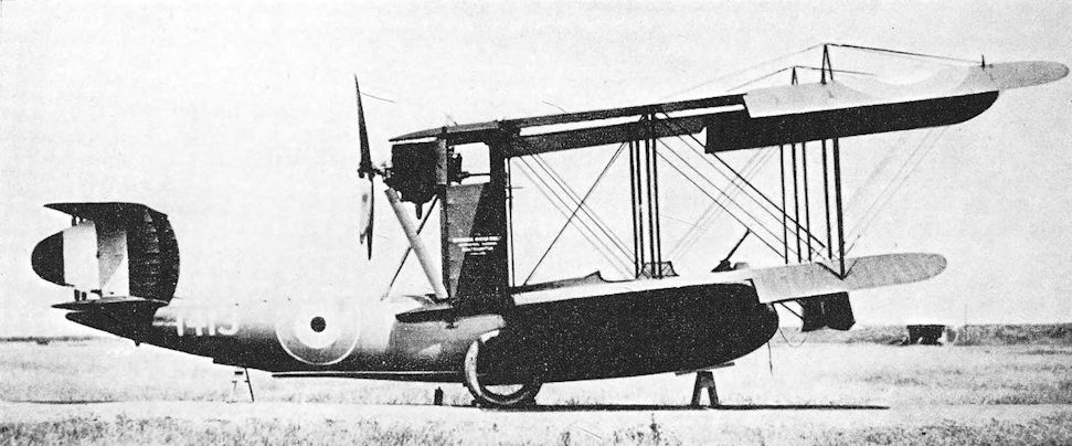
A.D. Flying Boat. Production aircraft with 200 h.p. Hispano-Suiza engine.
Once installed at the Admiralty, Harold Bolas became involved with design of the first A.D. flying-boat, a production version of which is shown here; N1522 of the RNAS.
Once installed at the Admiralty, Harold Bolas became involved with design of the first A.D. flying-boat, a production version of which is shown here; N1522 of the RNAS.
A.D. Flying Boat with 150 h.p. Hispano-Suiza engine.
The A.D. flying boat had a Linton Hope designed hull. Supermarine "built" the type under Contract AS5388/17, (N1520-N1529). N1525 bears Supermarine's logo on the anti-skid fins that were fitted between the interplane struts.
The A.D. flying boat had a Linton Hope designed hull. Supermarine "built" the type under Contract AS5388/17, (N1520-N1529). N1525 bears Supermarine's logo on the anti-skid fins that were fitted between the interplane struts.
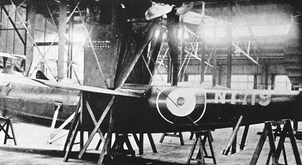
A.D. Flying Boat with hydrovanes fitted to the hull.
Alcock Scout
IN 1917, Flight-Lieutenant J. W. Alcock, who was later to achieve fame for his trans-Atlantic flight with Arthur Whitten Brown in 1919, was serving with No. 2 Wing, R.N.A.S., at Mudros, in the Aegean Sea. While there he made a single-seat fighter biplane, which he called the “Sopwith Mouse”, and which was also known as the Alcock A.1.
This aircraft consisted almost wholly of Sopwith Triplane and Pup components. The fuselage, undercarriage, and most of the lower wing belonged to a Sopwith Triplane, whilst much of the upper wing had originally belonged to a Pup. It appears that a new centre-section was made for the upper wing, and that a centre-section was also fitted to the lower wing. The fuselage appeared to rest on top of the lower main-plane. Two-bay interplane bracing was used, and the interplane struts converged downwards to meet the more closely-spaced spars of the lower wing. The gap was such that the upper wing was brought low above the fuselage, and interfered very little with the pilot’s view.
It is hard to determine how much of the tail unit came from other aircraft, but the rudder might have belonged to a Sopwith type. Triangular fins were fitted, one above and one below the fuselage; and the tail-skid was apparently attached to the rudder-post. The tailplane was mounted centrally on the fuselage.
The Alcock machine was at first fitted with a 100 h.p. Gnome Monosoupape rotary engine, but a 110 h.p. Clerget was later fitted. It is believed that some of the components were taken from the Sopwith Triplane which crashed at Mudros on September 3rd, 1917. Much of the mathematical work involved in the building of the aircraft was done by Commander Constantine of the Greek Navy, who was then in command of the Greek Air Force at Mudros.
Contrary to the official history, Alcock never flew his “Sopwith Mouse”, for it had not been completed when he was taken prisoner by the Turks on the night of September 30th, 1917: he and his crew (Lieutenant S. J. Wise and Lieutenant H. Aird) were captured when No. 2 Wing’s solitary Handley Page O/100 was forced down in the Gulf of Xeros.
But the Alcock Scout was completed and flown. While Alcock was in the civil jail at Seraskerat, Constantinople, he received this message from Wing-Captain F. R. Scarlett, C.B., D.S.O., on October 18th, 1917: “Your baby was taken for an airing, but is still having trouble with teeth. She has now been fitted with new clothing. Now a great improvement in health.” It is believed that the Alcock A.I was first flown on October 15th, 1917.
Early in 1918 the machine was flown over to Stavros by Flight-Lieutenant Starbuck, and it is believed that it was crashed there by that officer.
The foregoing history is based on notes provided by former members of No. 2 Wing, R.N.A.S., who were at Mudros when the Alcock A.I was built; it is very different from the account which appears in Volume V of The War in the Air, the official history. The latter account tells of an aircraft of Alcock’s design fitted with a Benz engine which had been taken from a Friedrichshafen bomber shot down in April, 1917, and goes on to relate how Alcock flew it to attack three enemy seaplanes on September 30th, 1917.
That story is inaccurate, however, for the Alcock A.1 could not have been fitted with a Benz engine, and Alcock was flying a Camel on the occasion in question. It may indicate that he designed an aeroplane round the Benz engine, for it was stated that drawings were sent home from Mudros.
SPECIFICATION
Power: 100 h.p. Gnome Monosoupape; 110 h.p. Clerget.
Armament: Two fixed, forward-firing Vickers machine-guns, synchronised to fire through the airscrew. Service Use: No. 2 Wing, R.N.A.S., Mudros; also flown at Stavros.

The serviceman gives scale to the A.1.
The Ruffy-Baumann School Biplanes
<...>
For elementary training purposes the Ruffy-Baumann company built a two-seat biplane which was in the same class as the D.H.6 and appeared to owe something to that aircraft. The installation of the 70 h.p. Renault engine was very similar to that of the R.A.F. ta in the D.H.6, and the windscreens and gravity fuel tank bore a strong resemblance to the corresponding components on the D.H.6. The Ruffy-Baumann biplane was more refined in general appearance, however, and lacked the primitive angularity of the “Clutching Hand”. The undercarriage embodied skid-like projections, each of which had a small auxiliary wheel at its forward end.
The elementary trainer was later improved by the removal of the skids from the undercarriage and by the addition of a blunt cowling to fair off the nose under the engine bearers. The gravity petrol tank was removed, and a horn-balanced rudder replaced the original plain surface. It was in this form that the machine became known as the Alliance P.1 when the Alliance Aeroplane Co., Ltd., expanded by absorbing a number of small manufacturers of whom the Ruffy, Arnell and Baumann Aviation Co. were one.

Ruffy-Baumann Elementary Trainer. This illustration shows the Ruffy-Baumann biplane in its early form with four-wheel main undercarriage.

Ruffy-Baumann Elementary Trainer. The aircraft with simplified undercarriage, cowled engine, and horn-balanced rudder.
Armstrong Whitworth F.K. 1
THE original aircraft manufacturing firm which bore the name of Armstrong Whitworth came into existence in 1914 as the Aeroplane Department of the large engineering firm of Sir W. G. Armstrong, Whitworth & Co., Ltd. The first works manager was that great Dutchman, Frederick Koolhoven.
The little single-seat scout which was designated Armstrong Whitworth F.K.1 was not Koolhoven’s first essay in aeroplane design, for he had earlier done much work on several of the Deperdussin monoplanes, but it was his first design for the Armstrong Whitworth company.
The Armstrong Whitworth F.K.1 was a rather frail-looking little biplane which appeared in September, 1914. Even at that early date it showed evidence of having been designed with an eye to production, for its layout was essentially simple. The fuselage was reminiscent of the pre-war Morane-Saulnier monoplanes; so also was the plan-form of the wing-tips. The tail unit betrayed further Morane influence, for there was at first no tailplane but only a balanced elevator. The aircraft had been meant to have the to 80 h.p. Gnome rotary engine, but only a 50 h.p. Gnome could be obtained. There was no alternative but to install the lower-powered engine.
The first flight of the F.K.1 was made by Koolhoven himself. The tail unit was subsequently modified, and a fixed tailplane and plain elevator were fitted. A further modification was the fitting of new, enlarged ailerons which had a pronounced inverse taper.
The F.K.1 was underpowered with only the very nominal 50 h.p. of its Gnome engine, and its performance was no improvement on that of the more powerful contemporary Sopwith, Bristol and Martinsyde Scouts. No development was undertaken.
SPECIFICATION
Manufacturers: Sir W. G. Armstrong, Whitworth & Co., Ltd., Gosforth, Newcastle-on-Tyne.
Power: 50 h.p. Gnome.
Performance: Maximum speed: 75 m.p.h. Stalling speed: 30 m.p.h.

Armstrong Whitworth F.K.1 with enlarged ailerons.

Armstrong Whitworth F.K.1 with its original ailerons.
Armstrong Whitworth F.K.3
IN the summer of 1914 it was officially decided to adopt the B.E.2C as a standard type for both the R.F.C. and the R.N.A.S., and among the first manufacturers to be awarded contracts for its production were Sir W. G. Armstrong, Whitworth & Co., Ltd.
When the necessary drawings were received from the Royal Aircraft Factory, study of them led the firm to declare the B.E.ac to be complicated and difficult to construct. Armstrong Whitworths offered to design and produce an aeroplane which would be structurally simpler than the B.E.2c but equally efficient. The firm were granted permission to do so, and Frederick Koolhoven produced the design of the F.K.3. Work began in August, 1915, and, after the successful completion of official trials, large orders for F.K.3S were placed with Armstrong Whitworth and Messrs Hewlett & Blondeau.
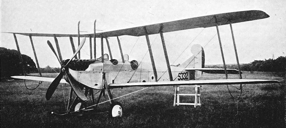
In general appearance the F.K.3 bore a certain resemblance to the B.E.2c, particularly in its original form, when it carried its crew in two separate cockpits similar in shape to those of the B.E., and the pilot occupied the rear seat.
An interesting experimental modification was made to an early F.K.3 in 1915. Koolhoven added a third mainplane above the normal biplane wings in order to measure the increased lift and drag produced by the arrangement. This machine flew well and had a remarkably flat glide. It seems probable that it may have provided some data for the design of the Armstrong Whitworth F.K.12 triplane.
Production F.K.3s showed several major differences from the prototype, chief of which was the interchange of the pilot’s and observer’s seats. The crew occupied one large communal cockpit, somewhat similar to that of the D.H.6. With the pilot in the front seat, the observer could use a gun much more effectively. Dual controls were provided. The shape of the fin and rudder was modified to be neater in appearance but greater in area than that of the prototype; the rudder was still a horn-balanced surface. The undercarriage was an interesting structure which included a central skid and yet had oleo shock absorbers attached to the fuselage, at a time when rubber cord was the almost universal shock absorbing medium. The design of the oleo components was influenced by the recoil mechanism of the famous French 75 mm gun.
The operational service of the F.K.3 was given in the Middle East theatre of war. In Macedonia the type was used by No. 47 Squadron, which arrived at Salonika on September 19th, 1916, and remained in service with that unit until 1918.
Proof of the F.K.3’s sturdiness was provided by an incident which occurred in the course of a combat over Hudova on December 22nd, 1916. The F.K.3 flown by Second Lieutenant W. H. Farrow (observer: Second Lieutenant F. C. Brooks) collided with an enemy machine. The Armstrong Whitworth’s starboard wheel struck the German biplane’s upper wing, and the enemy machine disappeared into the clouds below. Despite a troublesome engine, Farrow landed his F.K.3 safely at Snevce.
The F.K.3 was called upon to perform a variety of duties by No. 47 Squadron. Bombing attacks, such as that made on Hudova on February 1 ith, 1917, when four F.K.3s and a B.E.12 reached the target, were not uncommon. Hudova was bombed frequently, and on such raids the machine was usually flown without an observer, for it was unable to lift both bombs and a second crew-member.
Artillery cooperation and contact patrols were also performed by the hard-working F.K.3s, not without losses, for the enemy did not make the mistake of using only second-class or outmoded machines on the lesser fronts.
At home the F.K.3’s normal use was as a trainer, a duty for which its viceless flying characteristics made it admirably suitable. It was almost as foolproof as the D.H.6, but was much lighter on the controls than either “The Clutching Hand” or the B.E.2C. The F.K.3 was capable of performing all the aerobatics which were in practice at the time of its existence. The type was also used for training observers, when a camera gun was carried. To the R.F.C. it was familiarly known as the “Little Ack”, to distinguish it from the later F.K.8 or “Big Ack”.
After the adoption of the Avro 504 as the standard training aeroplane, the F.K.3 was almost completely supplanted, but a fair number survived until the Armistice. Some, indeed, were sufficiently long-lived to go on the British Civil Register as G-EABY, G-EABZ, G-EAEU and G-EALK. Of these, G-EABY at least was fitted with a plain vee undercarriage.
SPECIFICATION
Manufacturers: Sir W. G. Armstrong, Whitworth & Co., Ltd., Gosforth, Newcastle-on-Tyne.
Other Contractors: Hewlett & Blondeau, Ltd., Oak Road, Leagrave, Luton.
Power: 90 h.p. R.A.F. Ia; 105 h.p. R.A.F. Ib.
Dimensions: Span: 40 ft 0 5/8 in. Length: 29ft. Height: 11 ft 10 3/4 in. Chord: 5 ft 8 1/4 in. Gap: 5 ft 11 in. Stagger: 1 ft 11 5/8 in. at centre section, 1 ft 11 9/16 in. at outer struts. Dihedral: upper 3° 30', lower 2° 30'. Incidence: 1° 40'. Span of tail: 14 ft 3 in. Airscrew diameter: 9 ft.
Areas: Wings: upper 229 sq ft, lower 213 sq ft, total 442 sq ft. Ailerons: each 16 sq ft, total 64 sq ft. Tailplane: 27 sq ft. Elevators: 22 sq ft. Fin: 5-8 sq ft. Rudder: 9-5 sq ft.
Weights (lb) and Performance:
Engine R.A.F. 1a R.A.F. 1b
No. of Trial Report M.40 M.47
Date of Trial Report May, 1916 June, 1916
Type of airscrew used on trial T.7448 T.7448
Weight empty 1,386 I>375
Military load 80 80
Crew 360 320
Fuel and oil 230 235
Loaded 2,056 2,010
Maximum speed (m.p.h.) at ground level 87 -
1,000 ft 85 -
6,500 ft - 88
8,000 ft 81 -
10,000 ft - 80
m. s. m. s.
Climb to 1,000 ft 3 00 - -
2,000 ft 7 00 - -
3,000 ft 10 30 - -
4,000 ft 14 00 - -
5,000 ft 19 00 - -
6,000 ft 24 00 - -
6,500 ft 26 30 12 00
7,000 ft 29 00 - -
8,000 ft 36 00 - -
9,000 ft 41 00 - -
10,000 ft 48 56 - -
11,000 ft 66 00 - -
12,000 ft 74 00 - -
12,300 ft 78 00 - -
Service ceiling (feet) 12,000 13,000
Endurance at 8,000 (hours) 3 2 1/2
Tankage: Petrol: 28 gallons. Oil: 2-6 gallons.
Armament: One Lewis machine-gun on pillar mounting at the rear of the cockpit. The bomb load, carried in external racks, could include bombs of 16 lb, 100 lb, or 112 lb.
Service Use: Macedonia: No. 47 Squadron, R.F.C. Training: Used at various aerodromes, including No. 31 Training Squadron, Wyton; No. 35 Reserve Squadron, Northolt; Schools of Aerial Gunnery at Hythe and Turnberry; and at Stirling, Dymchurch and Marske. Also used in Egypt.
Production and Allocation: No precise figures for production and original allocations can be given, because the Armstrong Whitworth F.K.3 and F.K.8 were grouped together in the official statistics. Serial numbers indicate that at least 500 F.K.3S were ordered; and it seems obvious that the four Armstrong Whitworths delivered to Training Units in 1915 must have been F.K.3s, as also would be most of the eighty delivered in 1916. On October 31st, 1918, the Royal Air Force had sixty-two F.K.3s on charge: fifty-one were at schools and home aerodromes, six were in Egypt, three in Palestine, one was at an Aeroplane Repair Depot and one at an experimental unit.
Serial Numbers: 5328-5334, 5614 and 6186-6227 were ordered from Armstrong Whitworth under Contract No. 94/A/103. 5504-5553. A.1461-A.1510, A.8091-A.8140 and B.9501-B.9800 were ordered from Hewlett & Blondeau.
Notes on Individual Machines: A.1484: used by No. 35 Reserve Squadron. B.9518: became G-EABZ. B.9594: used at Marske. B.9603: became G-EALK. B.9612: became G-EAEU. B.9629: became G-EABY.
Costs:
Airframe without engine, instruments and gun £1,127 10s.
R.A.F. 1a engine £522 10s.
IN the summer of 1914 it was officially decided to adopt the B.E.2C as a standard type for both the R.F.C. and the R.N.A.S., and among the first manufacturers to be awarded contracts for its production were Sir W. G. Armstrong, Whitworth & Co., Ltd.
When the necessary drawings were received from the Royal Aircraft Factory, study of them led the firm to declare the B.E.ac to be complicated and difficult to construct. Armstrong Whitworths offered to design and produce an aeroplane which would be structurally simpler than the B.E.2c but equally efficient. The firm were granted permission to do so, and Frederick Koolhoven produced the design of the F.K.3. Work began in August, 1915, and, after the successful completion of official trials, large orders for F.K.3S were placed with Armstrong Whitworth and Messrs Hewlett & Blondeau.
In general appearance the F.K.3 bore a certain resemblance to the B.E.2c, particularly in its original form, when it carried its crew in two separate cockpits similar in shape to those of the B.E., and the pilot occupied the rear seat.
An interesting experimental modification was made to an early F.K.3 in 1915. Koolhoven added a third mainplane above the normal biplane wings in order to measure the increased lift and drag produced by the arrangement. This machine flew well and had a remarkably flat glide. It seems probable that it may have provided some data for the design of the Armstrong Whitworth F.K.12 triplane.
Production F.K.3s showed several major differences from the prototype, chief of which was the interchange of the pilot’s and observer’s seats. The crew occupied one large communal cockpit, somewhat similar to that of the D.H.6. With the pilot in the front seat, the observer could use a gun much more effectively. Dual controls were provided. The shape of the fin and rudder was modified to be neater in appearance but greater in area than that of the prototype; the rudder was still a horn-balanced surface. The undercarriage was an interesting structure which included a central skid and yet had oleo shock absorbers attached to the fuselage, at a time when rubber cord was the almost universal shock absorbing medium. The design of the oleo components was influenced by the recoil mechanism of the famous French 75 mm gun.
The operational service of the F.K.3 was given in the Middle East theatre of war. In Macedonia the type was used by No. 47 Squadron, which arrived at Salonika on September 19th, 1916, and remained in service with that unit until 1918.
Proof of the F.K.3’s sturdiness was provided by an incident which occurred in the course of a combat over Hudova on December 22nd, 1916. The F.K.3 flown by Second Lieutenant W. H. Farrow (observer: Second Lieutenant F. C. Brooks) collided with an enemy machine. The Armstrong Whitworth’s starboard wheel struck the German biplane’s upper wing, and the enemy machine disappeared into the clouds below. Despite a troublesome engine, Farrow landed his F.K.3 safely at Snevce.
The F.K.3 was called upon to perform a variety of duties by No. 47 Squadron. Bombing attacks, such as that made on Hudova on February 1 ith, 1917, when four F.K.3s and a B.E.12 reached the target, were not uncommon. Hudova was bombed frequently, and on such raids the machine was usually flown without an observer, for it was unable to lift both bombs and a second crew-member.
Artillery cooperation and contact patrols were also performed by the hard-working F.K.3s, not without losses, for the enemy did not make the mistake of using only second-class or outmoded machines on the lesser fronts.
At home the F.K.3’s normal use was as a trainer, a duty for which its viceless flying characteristics made it admirably suitable. It was almost as foolproof as the D.H.6, but was much lighter on the controls than either “The Clutching Hand” or the B.E.2C. The F.K.3 was capable of performing all the aerobatics which were in practice at the time of its existence. The type was also used for training observers, when a camera gun was carried. To the R.F.C. it was familiarly known as the “Little Ack”, to distinguish it from the later F.K.8 or “Big Ack”.
After the adoption of the Avro 504 as the standard training aeroplane, the F.K.3 was almost completely supplanted, but a fair number survived until the Armistice. Some, indeed, were sufficiently long-lived to go on the British Civil Register as G-EABY, G-EABZ, G-EAEU and G-EALK. Of these, G-EABY at least was fitted with a plain vee undercarriage.
SPECIFICATION
Manufacturers: Sir W. G. Armstrong, Whitworth & Co., Ltd., Gosforth, Newcastle-on-Tyne.
Other Contractors: Hewlett & Blondeau, Ltd., Oak Road, Leagrave, Luton.
Power: 90 h.p. R.A.F. Ia; 105 h.p. R.A.F. Ib.
Dimensions: Span: 40 ft 0 5/8 in. Length: 29ft. Height: 11 ft 10 3/4 in. Chord: 5 ft 8 1/4 in. Gap: 5 ft 11 in. Stagger: 1 ft 11 5/8 in. at centre section, 1 ft 11 9/16 in. at outer struts. Dihedral: upper 3° 30', lower 2° 30'. Incidence: 1° 40'. Span of tail: 14 ft 3 in. Airscrew diameter: 9 ft.
Areas: Wings: upper 229 sq ft, lower 213 sq ft, total 442 sq ft. Ailerons: each 16 sq ft, total 64 sq ft. Tailplane: 27 sq ft. Elevators: 22 sq ft. Fin: 5-8 sq ft. Rudder: 9-5 sq ft.
Weights (lb) and Performance:
Engine R.A.F. 1a R.A.F. 1b
No. of Trial Report M.40 M.47
Date of Trial Report May, 1916 June, 1916
Type of airscrew used on trial T.7448 T.7448
Weight empty 1,386 I>375
Military load 80 80
Crew 360 320
Fuel and oil 230 235
Loaded 2,056 2,010
Maximum speed (m.p.h.) at ground level 87 -
1,000 ft 85 -
6,500 ft - 88
8,000 ft 81 -
10,000 ft - 80
m. s. m. s.
Climb to 1,000 ft 3 00 - -
2,000 ft 7 00 - -
3,000 ft 10 30 - -
4,000 ft 14 00 - -
5,000 ft 19 00 - -
6,000 ft 24 00 - -
6,500 ft 26 30 12 00
7,000 ft 29 00 - -
8,000 ft 36 00 - -
9,000 ft 41 00 - -
10,000 ft 48 56 - -
11,000 ft 66 00 - -
12,000 ft 74 00 - -
12,300 ft 78 00 - -
Service ceiling (feet) 12,000 13,000
Endurance at 8,000 (hours) 3 2 1/2
Tankage: Petrol: 28 gallons. Oil: 2-6 gallons.
Armament: One Lewis machine-gun on pillar mounting at the rear of the cockpit. The bomb load, carried in external racks, could include bombs of 16 lb, 100 lb, or 112 lb.
Service Use: Macedonia: No. 47 Squadron, R.F.C. Training: Used at various aerodromes, including No. 31 Training Squadron, Wyton; No. 35 Reserve Squadron, Northolt; Schools of Aerial Gunnery at Hythe and Turnberry; and at Stirling, Dymchurch and Marske. Also used in Egypt.
Production and Allocation: No precise figures for production and original allocations can be given, because the Armstrong Whitworth F.K.3 and F.K.8 were grouped together in the official statistics. Serial numbers indicate that at least 500 F.K.3S were ordered; and it seems obvious that the four Armstrong Whitworths delivered to Training Units in 1915 must have been F.K.3s, as also would be most of the eighty delivered in 1916. On October 31st, 1918, the Royal Air Force had sixty-two F.K.3s on charge: fifty-one were at schools and home aerodromes, six were in Egypt, three in Palestine, one was at an Aeroplane Repair Depot and one at an experimental unit.
Serial Numbers: 5328-5334, 5614 and 6186-6227 were ordered from Armstrong Whitworth under Contract No. 94/A/103. 5504-5553. A.1461-A.1510, A.8091-A.8140 and B.9501-B.9800 were ordered from Hewlett & Blondeau.
Notes on Individual Machines: A.1484: used by No. 35 Reserve Squadron. B.9518: became G-EABZ. B.9594: used at Marske. B.9603: became G-EALK. B.9612: became G-EAEU. B.9629: became G-EABY.
Costs:
Airframe without engine, instruments and gun £1,127 10s.
R.A.F. 1a engine £522 10s.
Одна из ранних серийных машин.
One of the first seven F.K.3 aircraft, a batch ordered in April 1915.
Armstrong Whitworth F.K.3 in original form with pilot in rear, separate cockpits, and small fin and rudder.
One of the first seven F.K.3 aircraft, a batch ordered in April 1915.
Armstrong Whitworth F.K.3 in original form with pilot in rear, separate cockpits, and small fin and rudder.
Armstrong Whitworth F.K.3 in production form with pilot in front and modified tail-unit.
Armstrong Whitworth F.K.12
THAT excellent aero-engine, the 250 h.p. Rolls-Royce which was later named Eagle, was originally designed and developed as a power unit for seaplanes. About the end of January, 1916, the Admiralty transferred a few of these engines to the War Office for experimental purposes; and the aircraft manufacturers of the day were invited to submit designs for multi-seat escort fighters embodying the Rolls-Royce engine. No doubt it was hoped to produce an aeroplane capable of defeating the Fokker monoplane, which was then coming into menacing prominence.
Several firms submitted designs to meet the specification, which demanded a maximum endurance of seven hours to enable the machine to be used for anti-Zeppelin work if need be; but only Armstrong Whitworth, Sopwith and Vickers were awarded contracts for the construction of prototypes. All three designs were highly unorthodox, and all provided accommodation for their gunners in unusual positions.
The Armstrong Whitworth design was the F.K.12, a big triplane which appeared in two different forms. The version which apparently came first was probably the most remarkable British aeroplane of the 1914-18 war. Its central mainplane was of much greater span than the top and bottom wings, and on it the fuselage was mounted almost symmetrically. There was virtually no forward-reaching nose on the fuselage; the airscrew revolved just in front of the leading edge of the central wing.
The undercarriage consisted of a central unit carrying two main wheels on a sprung leg, and a small sprung wheel under each wing tip. A long pylon just behind the trailing edge of the bottom wing was fitted with a skid which kept the tail of the fuselage clear of the ground.
The central mainplane carried two nacelles for gunners, each of whom apparently was to have had a Lewis gun on a rocking-post mounting. The gunners were in front of the tractor airscrew and had a fine field of fire in all forward directions.
The second F.K.12 had a similar wing configuration, but was a much more cumbersome machine. The wing span and area were increased, and the wings had two bays of interplane bracing. The fuselage was more conventional in appearance, but was deeper and filled the gap between middle and bottom mainplanes. The long nose must have interfered with the gunners’ view. The wing-mounted nacelles were retained, but were of different form and were underslung from the centre wing. The undercarriage consisted of two twin-wheel units under the fuselage. Serial numbers were allotted for four prototypes, but it is doubtful whether all were built.
The Armstrong Whitworth F.K.12 was tested by Peter Legh, but its performance fell short of expectations. Furthermore, in common with the Sopwith and Vickers types, it appeared at about the same time as an effective British interrupter gear for machine-guns. Development was abandoned in favour of more conventional designs which could be effectively armed.
SPECIFICATION
Manufacturers: Sir W. G. Armstrong, Whitworth & Co., Ltd., Gosforth, Newcastle-on-Tyne.
Power: 250 h.p. Rolls-Royce.
Armament: Two Lewis machine-guns, one on a rocking-post mounting in each outboard nacelle.
Serial Numbers: 7838-7841.

The first version of the Armstrong Whitworth triplane, probably known as the F.K.5. It is believed that this aircraft never flew.
In this incarnation it was intended as an escort fighter. It was a triplane powered by a 250 hp Rolls-Royce Eagle V-12, and gunners were to be situated in each nacelle ahead of the propeller, giving them a clear field of fire forward. The gunners were to be armed with Lewis guns on post mounts. The middle wing had by far the largest span and carried the ailerons. The landing gear was eccentric.
In this incarnation it was intended as an escort fighter. It was a triplane powered by a 250 hp Rolls-Royce Eagle V-12, and gunners were to be situated in each nacelle ahead of the propeller, giving them a clear field of fire forward. The gunners were to be armed with Lewis guns on post mounts. The middle wing had by far the largest span and carried the ailerons. The landing gear was eccentric.

The Armstrong Whitworth F.K.12 anti-Zeppelin interceptor in its second form. Powered by a 250 hp Rolls-Royce V-12, the nacelles on the wings each housed a gunner with flexible machine gun. The F.K.12 combined an excellent engine with poor aerodynamic design. Not only did it have lots of drag-producing struts and wires, its triplane design was unfortunate in that the top wing was smaller than the middle wing. The top wing of biplanes and multiplanes creates the greatest lift and therefore should be the largest wing, with the other wings smaller for best aerodynamic efficiency.
Armstrong Whitworth F.K. 10
IT has been said, not without some truth, that almost every variation of the aeroplane form of aircraft was tried out during the 1914-18 war by one or other of the combatants. Monoplanes, biplanes and triplanes appeared in astonishing variety and profusion, and the quadruplane form was built and flown in Britain and Germany.
In Britain, at least four quadruplane types were built. The Supermarine concern built two large twin-engined quadruplanes, the P.B.29 of 1915 and the Night Hawk of 1916; the little Wight quadruplane single-seat fighter appeared in three slightly different forms; and the two-seat fighter-reconnaissance type was represented by the Armstrong Whitworth F.K.10. On the German side, at least two single-seat fighter quadruplanes were built; namely the Naglo with the 160 h.p. Benz, and the Euler with an Oberursel rotary engine.
The Armstrong Whitworth F.K.10 provided an excellent example of the striking originality of thought possessed by Frederick Koolhoven. The prototype had a slender fuselage, a fixed tailplane, and an ugly horn-balanced rudder; the engine was the 110 h.p. Clerget. It is doubtful whether any military equipment was fitted to this machine, and it seems probable that it may have been built solely to test the quadruplane wing arrangement.
The later prototypes had the same wing arrangement as the first, but the fuselage was more portly and the tail unit had been re-designed. There was now no fixed tailplane but only a balanced elevator reminiscent of the Morane-Saulnier monoplanes, and the vertical tail surfaces were of more pleasing form with approximately equal areas of fin above and below the fuselage. The 130 h.p. Clerget replaced the 110 h.p. engine of the first machine, but at least one F.K.10 had a 110 h.p. Le Rhone.
The pilot, from his cockpit ahead of the wings, had a remarkably good view in almost all forward and upward directions. This was one of the principal reasons for the adoption of the quadruplane layout, and good manoeuvrability was probably hoped for as a result of the use of four ailerons on each side and the compression of the wing area into a short span.
Armament was fitted to these F.K.10s, and consisted of a fixed synchronised Vickers gun for the pilot and a stripped Lewis on a rocking-post mounting for the observer.
A small batch of F.K.10s were ordered for the R.F.C. from Angus Sanderson & Co., presumably owing to Armstrong Whitworth’s pre-occupation with production of the F.K.8.
The R.N.A.S. were also interested in the type and ordered a few from other contractors. Two machines, N.511 and N.512, were built by the Phoenix Dynamo Manufacturing Co., Ltd., in 1917. The first was intended to be a two-seat fighter, for which purpose a Scarff ring-mounting was provided for the observer’s Lewis gun; the second machine, N.512, was built as a bomber. N.511 underwent its trials at Boroughbridge on April 26th, 1917.
The Phoenix-built F.K.10s differed in detail from the machines built by Armstrong Whitworth. They had horse-shoe cowlings instead of full circular; the coaming in front of the pilot’s cockpit was fuller and no windscreen was fitted; and small end-plates were fitted at the inboard ends of the bottom mainplanes.
All the F.K.10s were characterised by the heavily staggered wings connected by a single “plank” interplane strut and similar centre section struts, and by the peculiar single-strut undercarriage braced in three planes by cross-wires. The resulting structure did not look particularly strong, but presumably it worked well enough.
The R.F.C. flew an F.K.10 at Gosport, and the R.N.A.S. quadruplanes were flown at Manston; but the F.K.10 was not a good aeroplane, and production was not undertaken. The machine must have been sensitive on the elevators in the same way as the Moranes were, and it suffered from a form of wing flutter. The type was ultimately abandoned and four F.K.10s were scrapped at Manston in 1917.
A remarkable development was projected as the F.K.11. It was to consist of the fuselage of an F.K.10 fitted with fifteen narrow-chord mainplanes, heavily staggered and mounted close together.
SPECIFICATION
Manufacturers: Sir W. G. Armstrong, Whitworth & Co., Ltd., Gosforth, Newcastle-on-Tyne.
Other Contractors: The Phoenix Dynamo Manufacturing Co., Ltd., Bradford; Angus Sanderson & Co., Newcastle-on-Tyne.
Power: 110 h.p. Clerget; 130 h.p. Clerget; 110 h.p. Le Rhone.
Dimensions: Span: 27 ft 10 in. Length: 22 ft 3 in. Height: 11 ft 6 in. Chord: 3 ft 7 in. Gap: 2 ft 8 in. Stagger: 1 ft 5 in. Dihedral: 1° 30'. Incidence: 3°.
Areas: Wings: top 102-6 sq ft, second 92-6 sq ft, third 92-6 sq ft, bottom 102-6 sq ft; total 390-4 sq ft. Ailerons: each 8-4 sq ft, total 67-2 sq ft. Elevators: 16 sq ft. Fin: 1-9 sq ft. Rudder: 8 sq ft.
Weights (lb) and Performance:
Engine 110 h.p. Clerget 130 h.p. Clerget Manufacturer’s figures for 130 h.p.
No. of Trial Report M.77 M.82 -
Date of Trial Report Dec. 1916 Mar., 1917 -
Type of airscrew used on trial L.P.710C L.P.710C -
Weight empty 1,226 1,236 1,143
Military load 160 160 -
Crew 360 360 -
Fuel and oil 292 263 -
Weight loaded 2,038 2,019 1,804
Maximum speed (m.p.h.)
at ground level - - 105
6,500 ft 94 84 -
10,000 ft 87-5 74 99
m. s. m. s. m. s.
Climb to
6,500 ft 14 20 15 50 - -
10,000 ft 23 35 37 10 17 00
Service ceiling (feet) 13,000 10,000 -
Endurance (hours) 3 2 1/2 -
Armament: One fixed forward-firing Vickers machine-gun mounted centrally above the engine cowling and synchronised to fire through the airscrew; one Lewis machine-gun on rocking-post mounting or Scarff ring-mounting in rear cockpit.
Service Use: Flown by the R.F.C. at Gosport and by the R.N.A.S. at Manston.
Production and Allocation: Serial numbers were allotted for at least eleven Armstrong Whitworth F.K.10s, but all may not have been completed. One was delivered to the R.F.C. Training Unit at Gosport in 1916.
Serial Numbers: A.5212-A.5214: built by Armstrong Whitworth under Contract No. 87/A/1254. B.3996-B.4000: built by Angus Sanderson. N.511-N.512: built by Phoenix Dynamo Mfg. Co. under Contract No. C.P.135178/16. N.514: built under Contract No. C.P.100565/16.

Production-type F.K.10 with 110 h.p. Le Rhone engine.
Armstrong Whitworth F.K.8
TWO of the nineteen V.C.s awarded to members of the British flying services during the 1914-18 war were won on Armstrong Whitworth F.K.8s, yet the type is one of the less well-known aircraft of its period. Why this should be so is something of a mystery, for the F.K.8 gave excellent service on several fronts and proved itself a redoubtable opponent to the German single-seat fighters on more than one occasion. A possible reason for its obscurity might be that it did a good job of work, unobtrusively and without attracting undue praise or blame. It was popular with its pilots, to whom it was familiarly known as the “Big Ack”.
The F.K.8 was, of course, designed by Frederick Koolhoven, and bore a family resemblance to the earlier F.K.3. Like the F.K.3, it had staggered wings with two-bay bracing and greater dihedral on the upper wings than on the lower, and the vertical tail assembly was of typical Koolhoven design.
The prototype F.K.8 flew in May, 1916, and the first R.F.C. squadron to have the type was No. 35, which went to France fully equipped with F.K.8s on January 24th, 1917. No. 2 Squadron began to reequip with Big Acks in April, 1917; No. 10 received the type in July, 1917, No. 8 in August, 1917, and No. 82 went to France on November 20th, 1917, with the F.K.8 as its equipment. With these units in France, with Squadrons Nos. 17 and 47 in Macedonia, and with No. 142 in Palestine, the Big Ack gave sterling service as a reconnaissance and bombing machine until the Armistice.
The standard production F.K.8s had at first the 120 h.p. Beardmore engine, but later the 160 h.p. Beardmore was fitted. The engine cowling was at first a decidedly angular affair in which straight lines predominated, but later machines had a redesigned nose which was rounded in side elevation. There were long upright radiator blocks on either side of the fuselage, their upper halves forming an inverted V immediately in front of the centre line of the upper mainplane. The original distinctive undercarriage was a peculiar and rather complicated version of the old horizontal skid type, and shock absorption was by oleo members, as on the F.K.3.
Structurally, the F.K.8 had little to distinguish it, for it was a typical wire-braced biplane of wooden construction, but it had one feature which was uncommon in a British machine: namely, the use of inverted vee struts connecting the upper wings to the fuselage and the consequent absence of a centresection. Dual control was fitted: a small control column was provided on the starboard side of the observer’s cockpit, and was connected by an external link-rod to the starboard control arm from. which cables ran aft to the elevators. The observer thus had control over the elevators but not over the ailerons; and the rudder cables were provided with handgrips where they passed inside his cockpit, in order to give him emergency use of the rudder. The tailplane was adjustable, and was trimmed by a handwheel on the starboard side of the pilot’s cockpit.
The F.K.8 was well-liked by its crews, who regarded it as being strong and easy to fly. By the end of 1917 Big Acks were leaving the Armstrong Whitworth works at a rate of more than eighty per month, and production continued until July, 1918.
The final production version of the F.K.8 had the 160 h.p. Beardmore engine and retained the cleaner cowling, but improved radiators of reduced size were fitted, and on some machines a long horizontal exhaust pipe replaced the manifold with two short outlets which was more widely used. The most noticeable modification lay in the fitting of a plain vee undercarriage of more conventional design. As the illustrations show, two slightly different types of vee undercarriage were fitted.
Other motors fitted experimentally to the F.K.8 were the 150 h.p. R.A.F. 4a and the 150 h.p. Lorraine-Dietrich, the latter installation being characterised by an enormous spinner on the airscrew and twin exhaust stacks. These exhaust stacks were large and had a pronounced backwards rake. Machines to which the R.A.F. 4a was fitted were B.214 and B.215, and A.2696 had the Lorraine-Dietrich.
During the German offensive of March, 1918, the Big Acks did good work. On March 21st the machines of No. 35 Squadron dropped one hundred and sixteen 25-lb bombs and fired hundreds of rounds of ammunition on enemy troops and transport in the Maissemy area. They also directed artillery fire on to targets of massed infantry and cavalry with telling effect. Night bombing was another task allotted to the F.K.8s.
It was during this German offensive that Second Lieutenant Alan A. McLeod of No. 2 Squadron won the Victoria Cross for the action fought by him and his observer, Lieutenant A. W. Hammond, M.C., on March 27th, 1918. These two officers of No. 2 Squadron were returning from a bombing raid when they were attacked by a Fokker Dr.I, Hammond promptly shot it down, but seven more Fokkers appeared and McLeod was wounded after destroying one of them. Hammond shot down two more, but was wounded six times, and the F.K.8 was so badly damaged that the floor of the rear cockpit fell out. Hammond was barely conscious and McLeod had five wounds when the petrol tank was hit and flames engulfed the front cockpit.
Despite his wounds, McLeod climbed out on to the port wing and, with one hand on the burning control column, side-slipped to keep the flames away until the machine crashed in No-Man’s-Land. Hammond continued to fire at the remaining Fokkers until the crash knocked him unconscious. McLeod dragged him towards the British lines, receiving a sixth wound from a bomb-splinter while doing so. British troops rescued both airmen, who miraculously recovered from their terrible wounds, though Hammond suffered the amputation of one of his legs. Notification of the award of McLeod’s V.C. came through in due course, and Hammond received a bar to his M.C. McLeod was eighteen years old at the time.
The Big Acks of No. 8 Squadron took part in experiments in cooperation with tanks in 1918, for which purpose the unit was attached to the Tank Corps on July tst, 1918. Officers of the squadron exchanged duties with officers of the tank units, and significant experiments were conducted with radio telephony as a means of communication between the air observers and the tank crews. The short range of the early R/T apparatus led to the substitution of wireless telegraphy at the end of July, but these experiments were too late for a procedure to be devised before the Armistice.
It was an officer of No. 8 Squadron who won the second V.C. to be awarded to an F.K.8 pilot. On August 10th, 1918, Captain F. M. F. West, with Lieutenant J. A. G. Haslam as his observer, had dropped his bombs on an enemy gun position, and was still flying low when he was attacked by six enemy fighters.
Their first burst of fire almost severed his left leg, and no sooner had he lifted his useless limb clear of the controls than he was hit again in the other leg. Although faint from loss of blood and half-dead with pain, West managed to keep the F.K.8 on an even keel while Haslam drove off the attackers. West eventually landed in the British lines and refused to go to hospital until he had given the Tank Commander a detailed report of the enemy concentration points.
An unusual duty fell to the Big Acks of No. 35 Squadron on October 8th, 1918. It consisted of the maintaining of a smoke screen for two hours over the ground in front of the attacking British XIII Corps, west of Serain. The screen was produced and maintained by the continuous dropping of 40-lb phosphorus bombs by relays of aircraft.
A few Armstrong Whitworth F.K.8s were used on Home Defence duties, and one of those belonging to No. 50 (Home Defence) Squadron shot down a Gotha into the sea near the North Foreland on July 7th, 1917. The crew of the Armstrong Whitworth were Second Lieutenant F. A. D. Grace and Second Lieutenant G. Murray.
In Macedonia the F.K.8s of Nos. 17 and 47 Squadrons carried out many useful raids on enemy installations. One of the most notable of these raids was that made on Hudova aerodrome on May 23rd, 1918, when a ton of bombs was dropped. In September, 1918, No. 47 Squadron took part in an action which resembled one fought by No. 1 Squadron, Australian Flying Corps, in Palestine. On exactly the same date, September 21st, 1918, No. 47’s Big Acks and D.H.9s dropped 5,000 lb of high explosives and fired 1,200 rounds of ammunition into the retreating Bulgarian army in the Kosturino Pass, while on the Farweh road the Bristol Fighters of the Australian squadron took a dreadful toll of the retreating Turks caught, like the Bulgarians, in a valley: the Wadi el Far‘a.
The F.K.8 did not survive long in the R.A.F. after the Armistice, and only eight went on the British Civil Register. In Australia, two F.K.8s pioneered air travel: they were used by the Queensland and Northern Territory Aerial Service Co., Ltd., on the company’s first regular service over the route Charleville-Longreach-Cloncurry which opened on November 2nd, 1922.
SPECIFICATION
Manufacturers: Sir W. G. Armstrong, Whitworth & Co., Ltd., Gosforth, Newcastle-on-Tyne.
Other Contractors: Angus Sanderson & Co., Newcastle-on-Tyne.
Power: Standard: 120 h.p. Beardmore or 160 h.p. Beardmore. Experimental: 150 h.p. R.A.F. 4a and 150 h.p. Lorraine-Dietrich.
Weights (lb) and Performance:
Engine 120 h.p. Beardmore 160 h.p. Beardmore 150 h.p. R.A.F. 4a Lorraine-Dietrich
No. of Trial Report M.32 M.46 M.103 M.89
Date of Trial Report May, 1916 May, 1916 May, 1917 April, 1917
Type of airscrew used on trial L.P.920 - B. & C. 3120 L.P.3020 No. P. 1900
Weight empty 1,682 1,916 1,980 1,936
Military load 105 133 185 185
Crew 320 360 360 360
Fuel and oil 340 402 302 335
Weight loaded 2,447 2,811 2,827 2,816
Maximum speed (m.p.h.) at ground level - 98.4 - -
1,000 ft - - - -
2,000 ft - 97 - -
3,000 ft - - - 92
4,000 ft - 98 - -
5,000 ft - 97 - -
6,000 ft - 96 - -
6,500 ft - - 94 89
8,000 ft 83-5 93 - -
10,000 ft - 88 885 83
12,000 ft - 88 - -
m. s. m. s. m. s. m. s.
Climb to 1,000 ft - - 1 45 1 55 1 55
2,000 ft - - 3 50 - - - -
3,000 ft - - 6 00 - - - -
4,000 ft - - 8 10 - - - -
5,000 ft - - 11 00 - - - -
6,000 ft - - 13 55 - - - -
6,500 ft 19 00 15 25 16 25 16 30
7,000 ft - - - - - - 17 00
8,000 ft - - 20 05 - - - -
9,000 ft - - 23 49 - - - -
10,000 ft 35 00 27 5° 32 00 33 15
11,000 ft - - 32 20 - - 40 55
12,000 ft - - 39 00 46 25 - -
13,000 ft - - 49 00 57 10 - -
Service ceiling (feet) 12,000 13,000 15,000 13,000
Endurance (hours) 3 3 3 4
Tankage :
160 h.p. Beardmore R.A.F. 4a Lorraine-Dietrich
Petrol 47 1/2 gallons 36 gallons 40 gallons
Oil 4 3/4 gallons 6 gallons 5 gallons
Water 6 gallons Nil 1 1/2 gallons
Dimensions: Span: 43 ft 6 in. Length: (120 h.p. Beardmore) 30 ft 11 in.; (160 h.p. Beardmore) 31 ft; (R.A.F. 4a and Lorraine-Dietrich) 31 ft. Height: (120 h.p. Beardmore) 10 ft 11 in.; (160 h.p. Beardmore) 11ft; (R.A.F. 4a and Lorraine-Dietrich) 11 ft 3 in. Chord: 6 ft 6-7 in. Gap: (160 h.p. Beardmore) 5 ft 10-9 in.; (R.A.F. 4a) 5 ft 6 in.; (Lorraine-Dietrich) 5 ft 7 in. Stagger: (Beardmore and R.A.F. engines) 1 ft 7 3/4 in. at inner struts, 1 ft 7 11/16 in. at outer struts; (Lorraine-Dietrich) 1 ft 4 in. Dihedral: upper 3° 30', lower 2° 30'. Incidence: 2°. Span of tail: 13 ft 6 in. Wheel track: 6 ft. Tyres: 700 X 100 mm. Airscrew diameter: (160 h.p. Beardmore) 9 ft 3-8 in.; (R.A.F.) 9 ft 10 in.; (Lorraine-Dietrich) 8 ft 6 in.
Areas: Wings: 540 sq ft. Ailerons: each 17sq ft, total 68 sq ft. Tailplane:. 31 sq ft. Elevators: 26 sq ft. Fin: 10 sq ft. Rudder: 18 sq ft.
Armament: One fixed, forward-firing Vickers machine-gun mounted under the cowling and synchronised to fire through the airscrew; one Lewis machine-gun on Scarff ring-mounting on rear cockpit.
Service Use: Western Front: R.F.C. Squadrons Nos. 2, 8, 10, 35 and 82. H.Q. Communication Squadron. Home Defence: No. 50 Squadron. Macedonia: Part of No. 17 Squadron (the unit had nine F.K.8s on November 11 th, 1918); part of No. 47 Squadron (ten F.K.8s on November nth, 1918). Palestine: Part of No. 142 Squadron (seven F.K.8s on September 19th, 1918). Training: W/T Telegraphist School, Chattis Hill; School of Army Cooperation, Winchester; School of Photography, Maps and Reconnaissance, Farnborough; Air Observers’ Schools at Hythe, New Romney, Manston and Eastchurch; No. 4 School of Aerial Gunnery, Marske; Advanced Air Gunnery School, Lympne; No. 1 Training Depot Squadron, Stamford; No. 31 Training Squadron, Wyton; No. 39 Training Squadron, Narborough.
Production and Allocation: For the reasons given under this heading in the history of the Armstrong Whitworth F.K.3 precise figures are not available. A total of 1,596 Armstrong Whitworths of both types were delivered to the R.F.C., of which 777 went to the Expeditionary Force in France, 205 to the Middle East Brigade, eight to Home Defence units, and the remainder to Training Units.
On October 31st, 1918, 694 Armstrong Whitworth F.K.8s were on charge with the R.A.F. Of these, 182 were in France, twenty-one were en route to the Middle East, fifty-six were in Egypt and Palestine, forty-four were in Macedonia, and two were on the North-West Frontier of India. At home, 263 were in store, twenty-one were in transit to or at Aeroplane Repair Depots, thirty-six were at Aircraft Acceptance Parks or with contractors, sixty-six were at training units and various other aerodromes, and three were at experimental stations.
Serial Numbers: A.2683-A.2732: built by Armstrong Whitworth under Contract No. 87/A/508. A.9980-A.9999. B.201-B.330: built by Armstrong Whitworth under Contract No. 87/A/508. B.3301-B.3400: built by Armstrong Whitworth. B.4120, B.4165, B.4176, B.4200: rebuilds by No. 2 (Northern) Aeroplane Repair Depot. B.5751-B.5850: built by Armstrong Whitworth. G.3507-G.3706: built by Angus Sanderson. C.8401-8650: built by Armstrong Whitworth. D.5001-D.5200: built by Armstrong Whitworth. F.623. F.638, F.4231 (possible batch F.4221-F.4270). F.7384, F.7484. H.4473, H.4561, H.4573, H.4585, H.4612.
Notes on Individual Machines: Used by No. 2 Squadron: A.9998, B.218, B.246 (Aircraft “13”), B.248, B.258, B.288, B.315. Used by No. 10 Squadron: B.250, B.271, B.324, B.325, B.5772. Used at No. 1 Training Depot Squadron, Stamford: B.4120, B.4165, C.8548, C.8577, D.5075. Other machines: A.2696: fitted with 150 h.p. Lorraine-Dietrich engine No. 1018. B.214 and B.215: fitted with R.A.F. 4a engine. B.252: used at Marske. B.320: No. 50 Squadron. B.3326: used at A.A.G.S. Lympne. C.3648: No. 3 Training Squadron. C.8468: No. 3 Training Squadron. D.5150: became G-EAET. H.4473: became G-EAIC. H.4561: became G-AUCF. H.4573: became G-EAVT. H.4585: became G-EAVQ. H.4612: became G-EAJS.
Costs:
Airframe without engine, instruments or armament £1,365 17s. €825 os.
Engines:
120 h.p. Beardmore £825 0s
160 h.p. Beardmore £1,045 0s
150 h.p. R.A.F. 4a £826 0s.

F.K.8 with 150 h.p. Lorraine-Dietrich engine.

Although it looked somewhat ungainly, the FK8's performance was average for reconnaissance-bomber aircraft of the period - but far below that of the fighters, making it vulnerable if not escorted.
F.K.8 with 150 h.p. R.A.F. 4a engine and R.E.8-type exhausts.
F.K.8 with 150 h.p. R.A.F. 4a engine and R.E.8-type exhausts.

F.K.8 with R.A.F. 4a engine and B.E.12-type exhausts.

Armstrong Whitworth F.K.8. Beardmore engine with early type of cowling

Armstrong Whitworth F.K.8. Late production version with vee undercarriage and small radiators.

Armstrong Whitworth F.K.8. Beardmore engine in improved cowling.

Один из последних экземпляров машины, произведенной по лицензии компанией "Ангус Сандерсон", с бортовыми радиаторами, длинной выхлопной трубой и упрощенной тележкой шасси.
Late production F.K.8 with modified vee undercarriage and long exhaust pipe.
Late production F.K.8 with modified vee undercarriage and long exhaust pipe.

The Armstrong-Whitworth F.K.9 quadraplane two-seater fighter prototype powered by a 110 hp Clerget rotary. It led to the F.K.10 production two-seat fighter.
Armstrong Whitworth F.M.4, the Armadillo
IN 1917, Frederick Koolhoven left Armstrong Whitworth to become chief designer to the newly-formed B.A.T. Co., and responsibility for design work at Gosforth fell upon Mr F. Murphy. In the summer of 1918 there emerged from the Armstrong Whitworth works a heavy-shouldered, pugnacious-looking biplane named the Armadillo.
This was a small single-seat fighter which was test-flown in September, 1918. The fuselage was basically a simple wooden box-girder cross-braced in the usual fashion, and it completely filled the gap between the mainplanes; the upper wing was attached to the fuselage and had no conventional centresection. The forward portion of the fuselage was reinforced by duralumin girders of channel section, to which the petrol and oil tanks and the pilot’s seat were attached; and the sides of the fuselage were strengthened with a covering of three-ply.
The armament consisted of two fixed Vickers machine-guns, installed in the hump which faired the engine cowling up to the level of the upper wing. The original design included an additional Lewis gun mounted on the upper starboard wing root, firing forwards and upwards over the airscrew. It is not surprising that this third gun was not in fact fitted.
The undercarriage depended for shock absorption on rubber cord, but in its installation an interesting departure from the practice of the time was made. Instead of simply binding the axle to the apices of the vee-struts, a loop of elastic cord was attached to the fuselage at the top of each vee; from the lower end of each loop a steel cable ran down the inside of the fairings of the vee-struts, around a small pulley at the bottom of the vee, and then over the axle. Thus, any upward movement of the axle tensioned the cable and extended the rubber cord. The undercarriage underwent slight modification, and later had sturdier-looking legs.
The Armadillo came upon the wartime scene rather too late to be considered for development or production, but it seems doubtful whether it would have proved popular with pilots, for the view from the cockpit was poor in a forward and downward direction. From his position immediately behind the trailing edge of the upper wing the pilot had a fine view of the entire upper hemisphere, but for landing or ground attack work his view was severely limited by the bulky forward fuselage and engine cowling, and by the wings. Both wings were cut away at the roots, and an aperture was cut in the port side of the fuselage in front of the cockpit in an endeavour to improve the pilot’s view.
With the Armistice the Armadillo faded away, but no doubt the machine provided useful data for the design of its successor, the Ara.
SPECIFICATION
Manufacturers: Sir W. G. Armstrong, Whitworth & Co., Ltd., Gosforth, Newcastle-on-Tyne.
Power: 230 h.p. Bentley B.R.2 rotary engine.
Dimensions: Span: 27 ft 9 in. Length: 18 ft 10 in. Height: 7 ft 10 in. Chord: upper 5 ft 3 in., lower 4 ft 6 in. Gap: 3 ft 11 in. Stagger: 8 1/2 in. Dihedral: upper nil, lower 2°. Incidence: upper 2° 15', lower 1°. Span of tail: 11 ft 2 in.
Areas: Wings: 232 sq ft. Total aileron area: 36 sq ft. Tailplane: 17 sq ft. Elevators: 14 sq ft. Fin: 1-6 sq ft. Rudder: 6 sq ft.
Weights: Empty: 1,250 lb. Loaded: 1,860 lb.
Performance: Maximum speed at ground level: 125 m.p.h.; at 10,000 ft: 113 m.p.h. Climb to 10,000 ft: 6 min 30 sec. Ceiling: 24,000 ft. Endurance: 2 3/4 hours.
Tankage: Main fuel tank: 26 gallons. Auxiliary: 14 gallons. Total: 40 gallons.
Armament: Two fixed Vickers machine-guns mounted within the fuselage and above the engine, synchronised to fire forward through the airscrew.
Serial Number: X.19, built under Licence No. 18.
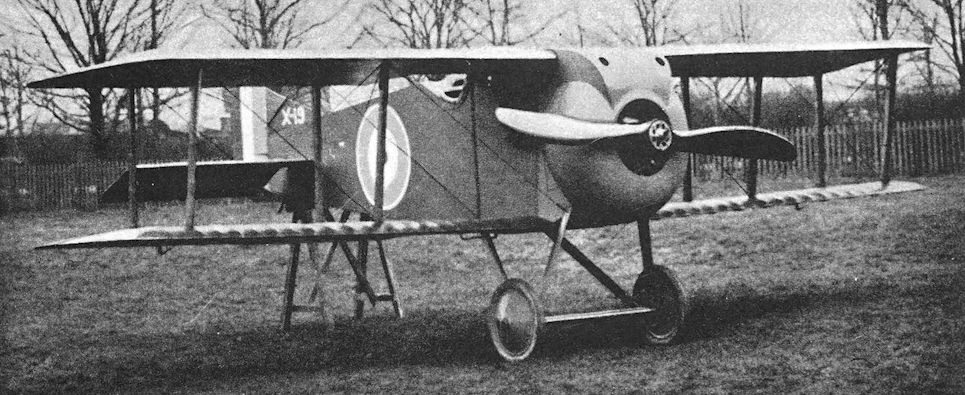
Three-quarter Front View of the Armstrong-Whitworth "Armadillo" as originally flown (220 h.p. B.R.2 Engine). The F.M.4 Armadillo, of which only one was built, was designed to the A1(a) fighter specification.
The Armadillo was found to possess unsatisfactory flying characteristics and a second prototype was completed but never flown.
The Armadillo was found to possess unsatisfactory flying characteristics and a second prototype was completed but never flown.

The Armadillo with modified undercarriage.
Armstrong Whitworth Ara
THE Ara did not appear until early in 1919, but it was a late wartime design, as serial numbers indicate, and as such it merits a place in this history. It was roughly contemporary with the Sopwith Snapper and Nieuport Nighthawk, and was built to much the same formula.
The Ara was designed by F. Murphy and, as might be expected, bore a family resemblance to the Armadillo. The likeness was particularly apparent in the disposition of the interplane struts and the shape of the vertical tail surfaces. The pilot’s view was better than that afforded by the Armadillo: the use of a conventional upper centre section raised the upper wing above the fuselage to the level of the pilot’s eyes. On the first Ara, F.4971, the lower wing was attached directly to the fuselage, but the second machine had increased gap and the fuselage was mounted between the wings in a manner reminiscent of the Bristol Fighter.
The fuselage lines were commendably clean, and the fairing of the nose and engine installation was particularly noteworthy. The good aerodynamics of the design were reflected in the excellent performance.
Like so many other good aeroplanes of its time, the Ara arrived too late; and its fate was sealed by the closing of the aircraft department of Sir W. G. Armstrong, Whitworth & Co., Ltd., late in 1919. There can be little doubt that the erratic behaviour of the A.B.C. Dragonfly engine must have detracted greatly from the aircraft’s capabilities and would, in any case, have discouraged further development of the design. (The A.B.C. Dragonfly is discussed at some length in the history of the Nieuport Nighthawk.)
SPECIFICATION
Manufacturers: Sir W. G. Armstrong, Whitworth & Co., Ltd., Gosforth, Newcastle-on-Tyne.
Power: 320 h.p. A.B.C. Dragonfly radial engine.
Dimensions: Span: 27 ft 5 in. Length: 20 ft 3 in. Height: 7 ft 10 in. Chord: upper 5 ft 3 in., lower 4 ft 6 in. Gap: 3 ft 10 1/2 in. Stagger: 11 1/2 in. Dihedral: 1° 30'. Incidence: upper 2° 45', lower 1° 15'.
Areas: Wings: upper 147 sq ft, lower 110 sq ft, total 257 sq ft. Total aileron area: 20-4 sq ft. Tailplane: 25 sq ft. Elevators: 24 sq ft. Fin: 2-5 sq ft. Rudder: 11 sq ft.
Weights: Empty: 1,320 lb. Loaded: 1,930 lb.
Performance: Maximum speed at ground level: 150 m.p.h.; at 10,000 ft: 145 m.p.h. Climb to 10,000 ft: 4 min 30 sec. Ceiling 28,000 ft. Endurance: 3 1/4 hours.
Armament: Two Vickers machine-guns mounted low down inside the fuselage and firing between the lowest pair of cylinders of the engine on either side. The guns were synchronised to fire forward through the revolving airscrew.
Serial Numbers: F. 4971-F. 4973.

The second Murphy-designed fighter, the Ara, first flew after the Armistice in 1918. Its A.B.C. Dragonfly engine was a failure.
The first Armstrong Whitworth Ara, F.4971.
The first Armstrong Whitworth Ara, F.4971.

The second Ara, with increased gap.
Siddeley S.R.2, the Siskin
IT would be almost true to say that the Siskin missed being the S.E.7 only because of the recommendations of the Burbidge Committee. The first rough outlines were sketched by Major F. M. Green shortly before he left the Royal Aircraft Factory to join the Siddeley-Deasy company. The original concept envisaged the use of the 300 h.p. R.A.F. 8 engine, a fourteen-cylinder two-row radial which was designed in September, 1916.
However, the real design work was done at the Siddeley-Deasy works, and it could fairly be claimed that the Siskin was the first all-Siddeley design. In common with such contemporaries as the Ara, Basilisk, Nighthawk, Snapper and Snark, the Siskin was not completed until 1919: it appeared in the summer of that year and underwent its official trials in July. Like those single-seaters, too, the Siskin was powered by the 320 h.p. A.B.C. Dragonfly I radial engine.
In the Siskin great care was taken to make the engine installation as clean as possible; a blunt spinner was fitted, and the engine cowling blended harmoniously with it. The airframe was predominantly a wooden structure. The basic fuselage box-girder had faired sides as far back as the cockpit and a rounded top-decking throughout its length. The pilot sat fairly high. The mainplanes were of unequal span and chord, and were characterised by centre-section bracing reminiscent of that of the Sopwith 1 1/2-Strutter, outwards-raked interplane struts, and raked tips. The tail-unit was of characteristic shape, yet embodied features that were to be seen in the S.E.5, R.E.8, and R.E.9, and also bore a certain resemblance to that of the Austin Greyhound. The undercarriage was of distinctive design: shock absorption was by means of the main single oleo legs, the lower ends of which were linked by radius-rods to the apices of a pair of vee-struts a short way aft.
The Siskin did not go into production in its original form, doubtless because of its Dragonfly engine. Yet with that engine it had a better performance than most of its contemporaries, and was one of the sweetest-natured of aeroplanes. It flew at the R.A.F. Pageant in 1920, when it was obliged to bring off a hurried forced-landing because of engine failure.
In view of its war-time origin, it is not without interest to trace the history of the Siskin’s later power unit, the Armstrong Siddeley Jaguar engine.
As related above, a fourteen-cylinder radial engine of 1,374 cu in. displacement was designed at the Royal Aircraft Factory in September, 1916. The new engine design was named R.A.F. 8 but was not built at Farnborough.
When Major F. M. Green joined the Siddeley-Deasy Motor Car Co., Ltd., early in 1917, his immediate responsibility was the development of the 230 h.p. B.H.P. engine. He asked for and obtained permission to develop the R.A.F. 8 engine, and put S. D. Heron in charge of the design work.
On April 5th, 1917, the Air Board issued a specification for a new aircraft engine. The specification, known as Scheme A, had been inspired by the Admiralty, and called for a radial engine of not more than 42 inches diameter capable of developing at least 300 h.p. This specification might have been that of the R.A.F. 8 itself, and J. D. Siddeley submitted the design to the Air Board. The engine which won an official contract was the Cosmos Mercury; nevertheless, Siddeley continued the development of the R.A.F. 8, and the name Jaguar was given to the new engine.
Cylinder design was by S. D. Heron, and the engine was the first to have an all-aluminium head with two valves inclined at a large angle to each other; this design feature was to be found in radial engines several decades later. J. D. Siddeley ordered the construction of the cylinders to be made similar to that of the Puma but when, in the middle of 1917, he instructed Heron to fit a new cylinder head with three valves, Heron resigned rather than do so.
Thereafter Jaguar development lagged for about two years. After the A.B.C. Dragonfly was proved to be a failure, Siddeley received a Government order for the Jaguar. Development was resumed by S. M. Viale, who re-designed several parts of the engine. J. D. Siddeley decided to remove the supercharger in order to simplify development of the basic design, and by the middle of 1920 the Jaguar was running quite well. In June 1922, by which time the stroke had been increased from 5 inches to 5 1/2 inches, the Jaguar passed the official Air Ministry type test and was ordered in quantities.
The original Siddeley Siskin ultimately fulfilled its first conception, for it was fitted with an early Jaguar engine in place of the erratic Dragonfly. The airframe design was subsequently considerably modified and, as the Armstrong Whitworth Siskin, equipped several R.A.F. fighter squadrons and appeared in other forms.
SPECIFICATION
Manufacturers: The Siddeley-Deasy Motor Car Co., Ltd., Park Side, Coventry.
Power: 320 h.p. A.B.C. Dragonfly I.
Dimensions: Span: upper 27 ft 6 in. Length: 21 ft 3 in. Height: 9 ft 9 in.
Areas: Wings: 247 sq ft.
Weights and Performance: No. of Trial Report: M.260. Date of Trial Report: July, 1919. Type of airscrew used on trial: A.B.8979. Weight empty: 1,463 lb. Military load: 218 lb. Pilot: 180 lb. Fuel and oil: 320 lb. Loaded: 2,181 lb. Maximum speed at 6,500 ft: 145 m.p.h.; at 10,000 ft: 143-5 m.p.h.; at 15,000 ft: 139 m.p.h. Climb to 6,500 ft: 4 min 30 sec; to 10,000 ft: 7 min 50 sec; to 15,000 ft: 13 min 50 sec. Service ceiling: 23,800 ft.
Armament: Two fixed and synchronised Vickers machine-guns mounted on top of the fuselage, firing forward.
Serial Numbers: C.4541-C.4546.

A Siddeley Siskin prototype in its original form, with A.B.C. Dragonfly engine; note the slim, unfaired interplane struts.
With the Dragonfly engine, the S.R.2 had a top speed of more than 145 mph.
With the Dragonfly engine, the S.R.2 had a top speed of more than 145 mph.
Austin-Ball A.F.B.1.
THE Austin-Ball A.F.B.1 was a single-seat fighting scout designed to the ideas of Captain Albert Ball, V.C., D.S.O., M.C., and represented his conception of the ideal single-seat fighter. At the beginning of April, 1916, Ball wrote home in the following enthusiastic terms:
“I have the plans now of a most wonderful machine. It will be heaps better than the Hun Fokker. I have been to the Major and he has given me full permission to fly it if I can get one out. I know that it will be a fine thing.”
On his first leave, Ball took the plans home with him and spent the winter of 1916-17 in trying to arrange for the construction of the machine, which was to be made by the Austin Motor Company. Early in 1917, while in London, Ball met a representative of the firm who was greatly discouraged at having failed to interest the Air Board in the Austin-Ball Scout. Ball went straight to Brigadier-General Sefton Brancker, then Director of Air Organisation, and made such strong representations that he came away with an order to build two machines at once and the promise that, if they were built in time and proved to be successful, a large production order would be placed.
The Austin-Ball A.F.B. 1 was characterised by an unusually deep fuselage which almost completely filled the gap between the mainplanes. The upper mainplane was at the level of the pilot’s eyes and he therefore had an excellent view all round the upper hemisphere. The mainplanes were swept back slightly, but were rigged with neither stagger nor dihedral. No fixed fin was fitted; and the rudder, of a pleasing oval shape, looked surprisingly small. The A.F.B.i was a thoroughly workmanlike aeroplane in every way, and its most remarkable feature lay in the disposition of its armament.
Ball gained most of his victories while flying a Nieuport Scout, and one of his favourite methods of attack was to stalk his victim from behind and below, gradually coming up under his enemy’s blind spot. Once in the position he favoured, Ball would let down his Lewis gun to the lower limit of its travel on the rail of its Foster mounting, and a short no-deflection burst of fire sufficed to despatch the enemy machine. It was, of course, a simple matter for Ball to rake the victim from nose to tail by a small back-and-forward movement of the stick. He used this same form of attack when he later flew S.E.5s.
It comes as no surprise, therefore, to learn that one of the Austin-Ball Scout’s Lewis guns was fitted to a Foster mounting on the upper wing. As on the Nieuport, this Lewis was mounted at an angle above the horizontal. But the installation of the A.F.B. 1’s other Lewis gun represented a radical departure from contemporary practice, for it was arranged to fire forward through the hollow airscrew shaft in the manner of latter-day moteurs-canons.
This may well have been the first instance of this particular method of mounting an aeroplane weapon, and was a commendable attempt to provide a gun on a tractor aeroplane firing forward along the line of flight. If Ball had the plans of the machine in April, 1916, it must have been designed some time before that date. The first British aeroplane fitted with a gun synchronising gear (a Bristol Scout with the Vickers mechanical gear) reached France only on March 25th, 1916; but whether the A.F.B.1’s armament installation was designed in ignorance of the existence of a British interrupter gear, or simply to avoid the use of such a gear, will probably never be known. It may well be that Ball preferred the Lewis to the Vickers gun: the Lewis, although a simpler weapon mechanically, was less well suited to firing with synchronising or interrupter gears. In the A.F.B.1 the breech of the lower Lewis gun projected backwards into the cockpit, where it was ideally accessible for reloading and stoppage-clearance.
Owing to the delays experienced in the machine’s design stages, it was not until July, 1917, two months after Ball’s death, that the A.F.B.1 was ready for testing. By that time the S.E.5 and Sopwith Camel were well into large-scale production and in squadron service in ever-increasing numbers. The A.F.B.1’s performance was startling, and it was described as comfortable to handle although its lateral control could have been better. However, the Air Board did not consider its superiority over the machines then in production to be great enough to justify interference with existing production plans, and the type was not developed further.
SPECIFICATION
Manufacturers: The Austin Motor Co. (1914), Ltd., Northfield, Birmingham.
Power: 200 h.p. Hispano-Suiza. Engines Nos. W.D.8302 and W.D.8354 were fitted.
Dimensions: Span: 30 ft. Length: 21 ft 6 in. Height: 9 ft 3 in. Chord: 5 ft. Gap: 4 ft 9 in. Stagger: nil. Dihedral: nil. Incidence: 2°. Span of tail: 11 ft 3 in. Tyres: 700 X 75 mm. Airscrew: (i) Grahame-White No. 512 - diameter 9 ft 6 in., pitch 7 ft 3 in. (ii) Tibbenham T.28097, No. 4205 - diameter 7 ft 9 in., pitch 10 ft 6 in. (iii) Vickers Series No. 192 - diameter 8 ft.
Areas: Wings: 290 sq ft. Ailerons: each 7-5 sq ft, total 30 sq ft. Tailplane: 16 sq ft. Elevators: 16 sq ft. Rudder: 8 sq ft.
Weights: Empty (with water): 1,525 lb. Military load: 87 lb. Pilot: 180 lb. Fuel and oil: 285 lb. Loaded: 2,077 lb.
Performance: No. of Trial Report M.122 M.122 M.122
Date of Trial Report July, 1917 July, 1917 July, 1917
Maximum speed (m.p.h.)
at ground level 138 - -
6,500 ft - 119 -
10,000 ft 126'5 115'5 118
12,000 ft 124 - -
13,000 ft 123 112 -
15,000 ft 120'5 - -
16,500 ft 118'5 - -
19,000 ft 114-5 - -
m. s. m. s. m. s.
Climb to
1,000 ft 0 40 - - - -
6,000 ft 4 45 - - - -
6,500 ft - - 8 25 6 35
10,000 ft 8 55 15 15 11 45
14,000 ft 14 30 - - - -
18,000 ft 23 00 - - - -
20,000 ft 29 55 - - - -
Service ceiling (feet) 22,000 16,000 17,000
Endurance 2 1/4 hours at full speed at 10,000 ft
Tankage:
Petrol:
Top (pressure) tank 9 gallons
Bottom (pressure) tank 20 gallons
Service (gravity) tank 3 gallons
Total 32 gallons
Oil 5 gallons
Water 9 gallons
Armament: Two Lewis machine-guns, one fixed to fire forwards through the hollow airscrew shaft, the other on a Foster mounting above the upper wing firing forwards and upwards over the airscrew.
Production: Two Austin-Ball A.F.B.1s were ordered under Contract No. 87/A/1524, but it is uncertain whether the second machine was completed.
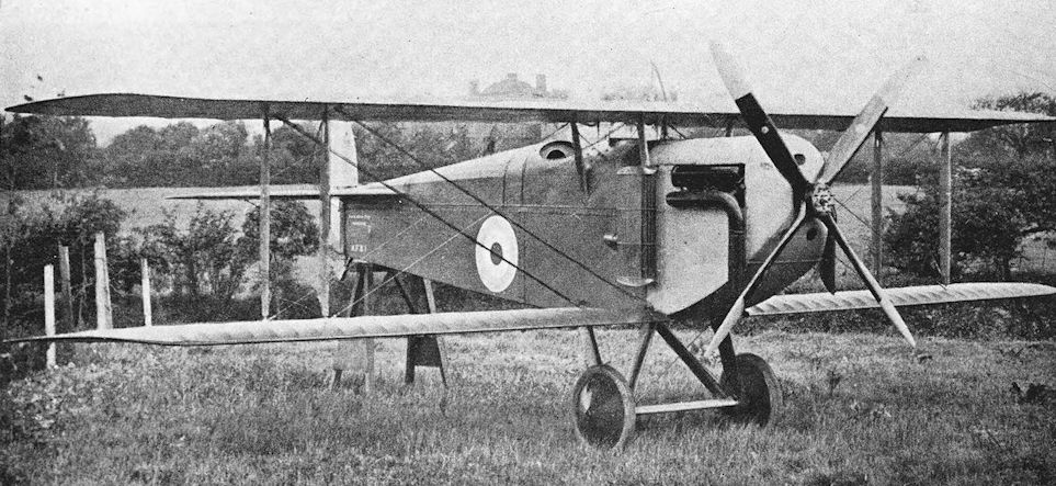
Three-quarter Front View of the Austin "Ball" Single-seat Fighter.
Austin A.F.T.3, the Osprey
THIS rather corpulent triplane was designed in 1917 to meet the requirements of the official specification A. 1A and was flown early in 1918. It was tested at Martlesham Heath in March of that year.
In construction the Austin A.F.T.3 was typical of the period, and was almost wholly made of wood. The fuselage was a wire-braced wooden box-girder with a rounded top-decking and fairings behind the engine-cowling. Particular care was devoted to detail design with a view to simplification of production and ease of maintenance in the field: only two patterns of fittings for the fuselage spacers were used, and any longeron could be replaced without disturbing the cross-bracing. All mainplanes on each side were interchangeable, as also were the ailerons.
The undercarriage was sprung in an unorthodox fashion. A special shock-absorber was mounted centrally under the spreader-bar, and from its sides cables ran to the apices of the undercarriage vees where they passed over pulleys and were connected to the ends of the axle. Thus any upward deflection of the axle extended the rubber cord within the shock-absorber.
The rudder was a plain balanced surface, and it was braced to the rear spar of the tailplane by cables which ran from the top of its axis. The incidence of the tailplane could be adjusted in flight.
It seems probable that the Austin Osprey was a competitor of the Sopwith Snipe. Its performance was quite good and it must have been manoeuvrable, but the triplane configuration imposed penalties of drag and made rigging rather more complicated. The Snipe was officially adopted, and the Austin triplane was not further developed. It was, however, flown well into the summer of 1918.
SPECIFICATION
Manufacturers: The Austin Motor Co. (1914), Ltd., Northfield, Birmingham.
Power: 230 h.p. Bentley B.R.2 rotary engine; engine No. E.X.3.
Dimensions: Span: 23 ft. Length: 17 ft 7 in. Height: 10 ft 8 in. Chord: 3 ft 8 1/2 in. Gap: upper 3 ft 1 1/2 in., lower 3 ft 6 1/2 in. Stagger: 2 ft 2 in. Dihedral: 30. Incidence: 30. Span of tail: 8 ft 2 1/2 in.
Areas: Wings: 233 sq ft. Ailerons: each 5-33 sq ft, total 32 sq ft. Tailplane: 23-4 sq ft. Elevators: 23-4 sq ft. Rudder: 5-5 sq ft.
Weights: Empty: 1,106 lb. Military load: 291 lb. Pilot: 180 lb. Fuel and oil: 311 lb. Loaded: 1,888 lb. Performance: No. of Trial Report: M.189. Date of Trial Report: March, 1918. Type of airscrew used on trial: Lang 4040. Maximum speed at 10,000 ft: 118-5 m.p.h.; at 15,000 ft: 110-5 m.p.h. Climb to 6,500 ft: 5 min 30 sec; to 10,000 ft: 10 min 20 sec; to 15,000 ft: 21 min 20 sec. Service ceiling: 19,000 ft. Endurance: 3 hours at 15,000 ft.
Tankage: Petrol: main (gravity) tank 26 gallons, service tank 14 gallons, total 40 gallons.
Armament: There were two fixed and synchronised Vickers machine-guns mounted on top of the fuselage, firing forwards; and at one time a Lewis machine-gun was fitted on the steel tube spars of the middle centre section.
Serial Number: X.15, built under Licence No. 17.

If nothing else this trim-looking triplane helps illustrate the point that for every winning design, a number of other design submissions fall by the wayside. First flown in February 1918, the company-funded Austin AFT 3 Osprey was designed to meet the same Air Board's Type A 1(a) requirement that led to the production contract for Sopwith's Snipe. Powered by a 230hp Bentley BR 2, the Osprey's top level speed was 118.5mph at 10.000 feet, this height being reached in 10 minutes 20 seconds. Armament consisted of three forward-firing .303-inch guns, of which two were fixed and synchronised Vickers, backed by an overwing Lewis that could be swivelled in elevation for 'belly-raking' an adversary's underside. Only the first of the three examples on which work had commenced was to be completed and flown. It is seen here at Farnborough in mid-June 1918, following its Martlesham Heath trials of March 1918.
Austin Greyhound
THE Greyhound was the last military aircraft to be designed and built by the Austin Motor Co. during the 1914-18 war. It was a handsome two-seat two-bay biplane, intended to replace the Bristol Fighter as a fighter-reconnaissance type; and it represented an attempt to provide the performance and equipment considered necessary after the experience of four years of war.
The lines of the fuselage reflected a compromise between comparative simplicity of structure and aerodynamic and operational efficiency, based on the usual contemporary method of construction. The pilot sat fairly high and directly under a large cut-out in the trailing edge of the centre section, and his downward view was helped by the narrow chord of the lower wings. The observer was immediately behind the pilot, as in the Bristol Fighter, and had an excellent field of fire for his Lewis gun.
The equipment of the Greyhound included a camera, wireless, oxygen and heating apparatus. Its performance was by no means bad, and it seems a pity that this interesting type was not further developed. In common with so many of its contemporaries, of course, it suffered from the temperamental nature of its A.B.C. Dragonfly radial engine. If it had gone into production it would have required a different power unit, but it seems that no attempt was made to develop the Greyhound in any way after the failure of the Dragonfly engine. (The story of the A.B.C. Dragonfly is related in the history of the Nieuport Nighthawk).
SPECIFICATION
Manufacturers: The Austin Motor Co. (1914), Ltd., Northfield, Birmingham.
Power: 320 h.p. A.B.C. Dragonfly I.
Dimensions: Span: upper 39 ft, lower 36 ft 7 in. Length: 26 ft 8 1/2 in. Height: 10 ft 4 in. Chord: upper 6 ft 4-8 in., lower 4 ft 3 in. Gap: 4 ft 11 7/8 in. Span of tailplane: 12 ft 9 5 in.
Areas: Wings: 400 sq ft. Ailerons: each upper 14-8 sq ft, each lower 7-8 sq ft, total 45 2 sq ft. Tailplane: 27-2 sq ft. Elevators: 19-8 sq ft. Fin: upper 2-76 sq ft, lower 2-3 sq ft, total 5-06 sq ft. Rudder: 9-9 sq ft.
Weights: Empty: 1,838 lb. Military load: 324 lb. Crew: 360 lb. Fuel and oil: 510 lb. Loaded: 3,032 lb.
Performance: Maximum speed at 6,500 ft: 129 m.p.h., at 10,000 ft: 126 m.p.h., at 15,000ft: 121 m.p.h. Climb to 6,500 ft: 6 min 20 sec, to 10,000 ft: 10 min 50 sec, to 15,000 ft: 19 min 40 sec. Service ceiling: 22,000 ft. Endurance: 3 hours.
Tankage: Petrol: 66 gallons. Oil: 8 gallons.
Armament: Two fixed, synchronised Vickers machine-guns firing forwards; one Lewis machine-gun on Scarff ring-mounting on rear cockpit.
Serial Numbers: H.4317-H.4319.
Avro 500
ALTHOUGH the part played by the Avro 500 in the 1914-18 war was a small one, it was an aeroplane of historical importance for it was one of the first machines to be ordered for the use of the British Army. The order was placed by the Government early in 1912, and was for three two-seat biplanes fitted with 50 h.p. Gnome engines.
Before the Gnome-powered Avros appeared, A. V. Roe completed a two-seat biplane with 60 h.p. E.N.V. engine, and this aircraft provided the basis for the military type. The Avro biplane with the Gnome engine was originally known as the Avro Biplane Type E, but some time later it was given the first of a new series of Avro type numbers which has continued until the present day. To quote Sir Alliott Verdon-Roe, as “a piece of drawing-office swank” the type number 500 was chosen as the beginning of the series.
The Avro 500 bore quite a strong resemblance to its E.N.V.-powered predecessor. It was an equal-span two-bay biplane with warping wings, and was of wooden construction. The undercarriage, like that of the biplane with the E.N.V. engine, was an unusual structure which recalled the arrangement on contemporary Nieuport monoplanes. The wheels were mounted on the ends of a transverse leaf spring which was attached to a sturdy central skid. There was no tailskid; instead, the machine rested on the bottom of the rudder, which was suitably shod. This arrangement was obviously a somewhat dangerous one, and a modified rudder was later fitted. The new rudder still acted as tailskid, but had a certain amount of vertical travel against the compression of a coil spring in order to provide a measure of shock absorption.
The first of the Avro 500s was in service in May, 1912, and when the Central Flying School of the R.F.C. was opened at Upavon on August 17 th of that year its equipment included two Avro 500s. Several of these Avro biplanes were used at the C.F.S., and the type was used in both the Naval and Military Wings of the early R.F.C. The original order was increased to twelve machines, and the contract enabled the firm of A. V. Roe & Co. to be soundly established.
A late refinement was the fitting of a comma-shaped rudder similar to that of the later Avro 504. This rudder was fitted with a proper tailskid. The shape of the skids below the wing-tips varied: some Avro 500s had half-hoops; others had simple braced skids which, in some cases, were fitted with two tiny wheels.
A single-seat version of the type also existed. It had a slightly longer decking on top of the nose portion of the fuselage. It may have been this version of the design which was known to the R.F.C. as the Avro Type Es.
The Avro 500 was also built for several private owners, and one at least had inversely tapered ailerons in place of wing-warping. It was owned by J. L. Hall.
By the time of the outbreak of hostilities in 1914 only a few Avro 500s survived, and they were used for training purposes. Perhaps the last was the one which survived at Chingford until August nth, 1915, when it was wrecked. This machine was fitted with a 100 h.p. Gnome fourteen-cylinder two-row rotary engine, an installation which was probably “home-made”.
SPECIFICATION
Manufacturers: A. V. Roe & Co., Brownsfield Mills, Manchester.
Power: 50 h.p. Gnome. At least one installation of a 100 h.p. Gnome was made.
Dimensions: Span: 36 ft. Length: 29 ft. Airscrew diameter: 9 ft.
Areas: Wings: 335 sq ft.
Weights; Empty: 900 lb. Loaded: 1,300 lb.
Performance: Maximum speed: 62 m.p.h.
Service Use: Flown by No. 3 Squadron R.F.C. and at the Central Flying School before the war. Was used as a trainer in the early months of the war; e.g. at Chingford.
Serial Numbers: 41, 51-53, 94, 150, 285, 288-291, 404-406, 430, 432, 433, 448.

Laurence Hall at Hendon with his Avro 500 two-seater with inversely-tapered ailerons.

The Avro 500 prototype with 50 h.p. Gnome rotary engine and the original sprung rudder.

Avro 500 of the Royal Flying Corps. Single-seat version with modified rudder (Avro Type 502 ES).

Avro 500. Two-seater with final form of rudder and constant-chord ailerons.
Avro 503
THE Avro company produced their first seaplane type in May, 1913. It was a large tractor biplane, powered by a 100 h.p. Gnome fourteen-cylinder engine, and was originally known as the Avro Type H. Later, the type number 503 was bestowed upon the aircraft.
A. V. Roe & Co. were not without some experience in the construction of seaplanes, for an Avro tractor biplane had been used in 1911 by Commander Oliver Schwann m his experiments, aimed at producing a seaplane, which were conducted at Barrow-in-Furness. The company also built the airframe of the Waterbird Curtiss-type biplane for the Lakes Flying Co.
The Avro 503 bore a certain resemblance to the Avro 500, particularly in the shape of its fuselage and tail unit. The upper wing was of slightly greater span than the lower, and was fitted with inversely-tapered ailerons. The main floats were single-step pontoon-type structures, covered with rubber-proofed cloth and sprung internally by rubber cord. The tail float was attached to the bottom of the rudder and moved bodily with it - an interesting analogy to the use of the base of the Avro 500’s rudder as a tail-skid.
The test-flying of the Avro 503 was carried out at Shoreham by F. P. Raynham, assisted by John Alcock.
A few examples of the type were built, and one was sold to Germany. Piloted by Leutnant Langfeld, this aircraft was the first to fly from the German mainland to Heligoland; the flight, with a passenger, was accomplished on September 6th, 1913.
The Germans must have thought highly of the Avro 503, for the Gotha WD.1 seaplane which first appeared in February, 1914, was an unashamed copy of the Avro. In a German description published in June, 1919, the Gotha WD.1’s sprung floats and tail-high floating attitude were hailed as innovations, but no mention was made of their British origin. Whereas the Avro company built few other seaplanes, the Gotha concern developed a long series of successful floatplanes from the WD.1.
The Avro 503 was also supplied in small numbers to the R.N.A.S. At least one was sent to the Isle of Grain for assembly; there it was test-flown and handed over to Commander J. W. Seddon. It is believed that this seaplane later participated in a bombing attack on Zeebrugge.
The ultimate fate of that Avro 503 is unknown, and it is uncertain how many aeroplanes of the type were supplied to the R.N.A.S. At Eastchurch an Avro 503 was flown with a wheel undercarriage, and was used there for training purposes. This aircraft had bracing struts on the overhanging portions of the upper wings, and was fitted with enlarged ailerons.
SPECIFICATION
Manufacturers: A. V. Roe & Co., Brownsfield Mills, Manchester.
Power: 100 h.p. Gnome.
Dimensions: Span: upper 50 ft, lower 47 ft. Length: 33 ft 6 in. Chord: 6 ft.
Areas: Wings: 567 sq ft.
Weights: Loaded: about 2,200 lb.
Service Use: R.N.A.S., Eastchurch. Serial Numbers'. 16.

The original Avro 503 float seaplane.
Avro 504
ALTHOUGH it performed few resounding feats of arms, the Avro 504 in its great variety of forms is assured of a place of honour in our aircraft history. Whether it is remembered as a delightful trainer of the war period or as a friendly aeroplane popping into and out of improbable fields as a joy-riding machine in the inter-war years, its immortality is secure. Above all, it was the aircraft which helped to lay the foundations of decades of safe and logical flying instruction.
The Avro 504 was more closely related to the Avro 500 than to any other preceding Avro type. Construction of the first 504 was begun in April, 1913, and its first tests were carried out at Brooklands in July of that year. The machine made its debut at Hendon on September 20th, 1913, as an entrant in the second Aerial Derby.
When the prototype Avro 504 first appeared, it had the 80 h.p. Gnome rotary engine installed in a nose-bearing mounting and within a cowling of square cross-section; the cowling had an arched top and bulged sides. The fuselage was a typical wire-braced wooden box-girder with the upper longerons quite straight in side elevation. The fuselage terminated in a vertical stern-post to which was attached a comma-shaped rudder; there was no fin, and the tailskid was attached directly to the bottom of the rudder. The main undercarriage was an original variation on the wheels-and-skid theme. There was a long central skid, and each main undercarriage leg carried its own shock absorber encased in a fairing. Each shock absorber consisted of 8 ft 8 in. of rubber cord in tension. The two-bay wings were of equal span and had a pronounced stagger. Each wing panel had only five fully formed ribs, which also served as compression members. Light spanwise stringers were let into these ribs, and the remaining contour-forming ribs consisted of strips of wood which were fastened to the leading edge, spars, stringers, and trailing edge. Lateral control was obtained by the curious device of warping ailerons. Although separate surfaces, these ailerons were secured at their inboard ends; they were inversely tapered, and their broad outer ends were warped by means of cables. Upper and lower ailerons were connected by a strut.
It was at once obvious that, with the possible exception of the warping ailerons, the Avro 504 was a thoroughly workmanlike aeroplane and considerably in advance of most of its contemporaries in design, construction and performance.
Much of the early flying of the 504 was done by F. P. Raynham. Flown by him, the machine was placed fourth in the second Aerial Derby at an average speed of 66.5 m.p.h.
Another contest in which the prototype 504 took part, again flown by Raynham, was the so-called “War of the Roses” contest, flown off on October and, 1913. In this, the Avro firm had accepted a challenge to a cross-country race against Dr Christie’s new Blackburn monoplane, flown by Harold Blackburn. A trophy was provided by the Yorkshire Evening News, and the course was Leeds-York-Doncaster-Sheffield- Barnsley-Leeds, a total distance of 100 miles. Visibility was very bad, and Raynham, who was over completely strange territory, had to abandon the race when near Barnsley.
The Avro 504 underwent certain modifications early in its career. The engine was given a new nose-bearing support made of bent steel tubing, over which was fitted a new cowling of rather bulbous appearance but better streamline form. Lateral control with the warping ailerons was not particularly effective, so freely-hinged conventional ailerons of constant chord replaced the original warping controls.
On November 24th, 1913, Raynham flew the machine to Farnborough to undergo official tests. Over a measured course the Avro clocked a speed of 80-9 m.p.h. and climbed to 1,000 feet in 1 min 45 sec; the stalling speed was 43 m.p.h. The tests were carried out with a passenger and three hours’ fuel on board.
These performance figures made a deep impression at the time, but their impact was somewhat lessened when, only five days later, the Sopwith Tabloid put up an even better performance in the same tests.
Raynham made several outstanding flights on the Avro 504. On February 4th, 1914, he flew the machine to a height of 15,000 feet, thereby comfortably exceeding the existing British altitude record of 13,140 feet which had been set up by Captain J. M. Salmond on a B.E.2. Raynham had taken off from Brooklands, and from his machine’s ceiling he glided to Hendon, about twenty miles away, with his engine off. After gliding down for twenty-five minutes he was over Hendon at 5,000 feet, so he spiralled down and landed there without again using his engine.
This flight was a magnificent exhibition of airmanship, but the climb could not count as a record because it was not officially observed. Six days later Raynham made a formal attempt on the altitude record and, with MacGeagh Hurst as passenger, took the Avro to 14,420 feet.
Soon after these flights, the Avro 504 was bought by the Daily Mail and toured the country giving exhibition flights. The Avro’s new owners required it to be flown from the sea at coast resorts; the manufacturers therefore made and provided a float undercarriage which was interchangeable with the normal wheels. A floatplane version was exhibited at the Olympia Aero Show in March, 1914. This particular Avro 504 was probably one of the first production machines, for the upper longerons of its fuselage sloped downwards behind the cockpits.
When the prototype was given its float undercarriage a change of power-plant was made at the same time. It was thought that the original 80 h.p. Gnome, with its actual output of little more than 62 h.p., might not provide sufficient power for the heavier seaplane version; and it was replaced by an 80 h.p. Gnome Monosoupape seven-cylinder rotary engine, which was supposed to be more powerful than the ordinary Gnome of the same nominal power. The choice was an unfortunate one, for the new engine proved to be far from satisfactory and gave a great deal of trouble. It finally brought about the destruction of the Avro 504.
During the Daily Mail tour the Avro was flown by F. P. Raynham and George Lusted, and its first flight as a seaplane was made at Paignton in April, 1914. In August it was at Shoreham, on floats. It was commandeered as soon as war was declared on the 4th of that month but was destroyed two days later: the engine failed as Raynham took off to deliver the machine to the Services, and he had insufficient height to avoid crashing on land.
In the early summer of 1914 the War Office ordered twelve Avro 504s and the Admiralty ordered one. In the construction of these machines there arose a remarkable example of lack of cooperation between the War Office and the Admiralty. Before acceptance of the type for Service purposes the design of the airframe had been studied by both Departments. The War Office accepted the structure in its designed form, but the Admiralty requested that spars of slightly greater cross-section be fitted. Avros, looking ahead to further orders, naturally wished to avoid the production complications which the use of different spars would mean, and asked the War Office to adopt the size of spar specified by the Admiralty. This the War Office declined to do. Consequently all the Admiralty Avro 504 variants had slightly larger spars than the machines which were built for the R.F.C., an anomaly which persisted until the amalgamation of the R.F.C. and R.N.A.S. in 1918, by which time spars of the original dimensions had been standardised in the 504K. All the production 504s had one feature in common: the rear fuselage was modified to be symmetrical in side elevation, so that the upper longerons sloped downwards behind the rear cockpit.
In the R.N.A.S. the Avro was frequently referred to as the Avro 179, a designation obtained by using the serial number of the first machine accepted by the Admiralty. Inevitably, the use of this designation has led to some confusion.
Some of the R.F.C. Avros were delivered before the outbreak of war, and the remainder were handed over soon afterwards. When No. 5 Squadron went to France on August 13th, 1914, its equipment included a few Avro 504s; but the type was never used in large numbers by front-line units. In fact, the greatest known number of Avros on the strength of the R.F.C. squadrons in France is only thirteen. On March 10th, 1915, No. 1 Squadron had eight, No. 3 had one, and No. 5 had four. Six months later the R.F.C. had seven in France, four with No. 1 Squadron and three with No. 5.
Service use in the field showed that the Avro 504’s flight endurance was too short, and later production aircraft had increased tankage which brought the endurance up to 4 1/2 hours.
One of the Avros of No. 5 Squadron was the first British aeroplane to be brought down by the enemy. On August 22nd, 1914, the machine flown by Lieutenant V. Waterfall (observer, Lieutenant C. G. G. Bayly) was shot down by infantry fire in Belgium, and it has been surmised that this Avro may have provided the Germans with the first positive evidence that British forces were in the field against them.
Commander Samson’s Eastchurch Squadron of the R.N.A.S. received its first Avro 504 on November 27th, 1914. This machine set out to bomb the submarine depot at Bruges on December 14th with four 16-lb bombs but Flight Sub-Lieutenant R. H. Collet, its pilot, could not find Bruges in bad visibility, and bombed the Ostend-Bruges railway line instead.
In common with its contemporaries, the Avro 504 had not been designed to carry any kind of offensive armament, and it was flown from the rear seat. The observer sat directly under the centre-section and had a centre-section strut at each corner of his cockpit. The chances of operating a machine-gun satisfactorily from that position were remote indeed. Nevertheless, various attempts were made in the field to provide some kind of useful armament.
One of the earliest of these attempts was made on Avro 504 No. 383 in mid-October, 1914. The Avro had been delivered to No. 5 Squadron on October 15th, and within a few days it had been fitted with a Lewis gun by its pilot, Second Lieutenant L. A. Strange, who was assisted by Captain L. da C. Penn-Gaskell. The “gun-mounting” would probably have delighted Mr Heath Robinson, and is best described in Wing-Commander Strange’s own words (in his book Recollections of an Airman):
“The mounting consisted of a metal tube, which I carefully selected from the tail boom of a wrecked Henri Farman. The gun lay on the top of the fuselage decking, while a piece of rope, lashed around its centre of balance, was passed up over the metal tube and fixed to the cross member of the front seat tank bearer, for it must be remembered that in those days the front seat was on top of the petrol tank. A pulley on the rope enabled the observer to sling the gun up into mid-air and fire it all round as well as back over the pilot’s head, with the aid of a stock from the shoulder.”
On October 22nd, 1914, Strange and Penn-Gaskell carried out what was probably the first ground-strafing attack of the war when they brought the Avro’s Lewis gun into action against a train and enemy troops at Perenchies siding. Exactly one month later, Lieutenant Strange, with Lieutenant F. G. Small as his observer, forced down an Albatros two-seater near Neuve-Eglise.
Military actions in which the Avro 504 took part were few, but the most audacious and brilliant by far was the R.N.A.S. raid on the Zeppelin sheds at Friedrichshafen, Lake Constance.
While Strange and Penn-Gaskell were strafing Perenchies in No. 383, Lieutenant Noel Pemberton Billing of the R.N.V.R. was on his way to Belfort to prepare for the attack; he arrived there on October 24th, 1914. When his preparations were complete he returned to England on October 28th to collect the aeroplanes and pilots for the execution of the raid.
A special flight of four Avro 504s had been formed at Manchester under Squadron Commander P. Shepherd, and the pilots were Squadron Commander E. F. Briggs, Flight Commander J. T. Babington, Flight-Lieutenant S. V. Sippe and Flight Sub-Lieutenant R. P. Cannon. The Avros, officers and eleven air mechanics arrived at Belfort by night on November 13th, ic) rq.. Soon after their arrival Squadron Commander Shepherd was taken ill; the weather was bad, and a strong easterly wind delayed the attack for a week.
On Saturday, November 21st, the weather improved sufficiently for the raid to take place, and the Avros were brought out for engine and bomb-rack tests. The aeroplanes were brand-new: they were, in fact, the first four Avros to be delivered to the Admiralty, and were numbered 179, 873, 874 and 875. Their 80 h.p. Gnome engines were not new, however, which was probably one reason why no test flights had been made with the aircraft; the raid itself was their first flight. There was at that time no such thing as a standard bomb-rack, and the Avro company designed and made the racks for the four machines. A. V. (later Sir Alliott Verdon) Roe said they were “a Heath Robinson job”, but they served well enough in the event. Stowage was provided for four 20-lb high explosive bombs and four incendiaries, but for the raid each aircraft carried only four 20-lb bombs.
The Avros left Belfort at five-minute intervals. Squadron Commander Briggs was first to go on No. 873, followed by Babington on 875 and Sippe on 874. Cannon’s machine broke its tailskid and was unable to take off. Over the target Sippe’s fourth bomb refused to leave the rack, but two of the eleven which dropped in the target area did all that was necessary. These fell on the airship sheds. One damaged a Zeppelin which was inside; the other destroyed the gas-works, which exploded and did great damage. The raiders did not escape unscathed, for Briggs was shot down and nearly lynched after crashing. No. 875 was later on the strength of No. 1 Squadron, R.N.A.S., but did not return from a raid on enemy positions on February 16th, 1915: its pilot on that occasion was Flight-Lieutenant E. G. Rigall.
The Avro 504 was less successful against the Zeppelin in its own element. The L.Z.38 was intercepted by Flight Sub-Lieutenant Mulock of Westgate R.N.A.S. Station about 3.30 a.m. on May 17th, 1915, but the airship climbed away too rapidly to allow Mulock to attack with his Avro’s load of two grenades and two incendiary bombs.
That same night, soon after Mulock’s adventure, Flight Commander A. W. Bigsworth, in another Avro, was pursuing the L.Z.39 towards Ostend. At 10,000 feet over the town he was 200 feet above the airship, and he dropped his four 20-lb bombs on it. Smoke issued from the Zeppelin’s stern, but it was not destroyed. Ultimately, and in a damaged condition, it made a rough landing at Evere.
With the standardisation of the B.E.2C the Avro ceased to be a front-line aircraft with the R.F.C., but continued in limited service with the R.N.A.S. In point of fact, the Avro company were at one time told that they would have to stop making 504s, which were regarded as obsolete, and undertake the manufacture of B.E.2c’s; production of the Avro might continue until instructions for the building of the B.E.2 were issued. Fortunately, those instructions were never forthcoming.
The basic design was modified in detail as time went on, and each successive variant was identified by the addition of a suffix letter to the Avro’s type number. The 504A retained the 80 h.p. Gnome engine, but had ailerons of reduced span and interplane struts of broader chord. On some 504As the lower wingroots were uncovered for about 12 inches on either side in order to improve the downward view. The tailskid remained attached to the bottom of the rudder. The first true 504As were the fifty machines numbered 2890-2939, but the designation is sometimes loosely applied to the sixty-three production 504s which had preceded them. The 504A was built in considerable numbers.
As part of the natural sequence of events, the Avro was relegated to training duties after its withdrawal from active service. Dual control had to be installed, and Avros designed a neat dual control umt comprising seats, bearers, control columns, rudder bars and heel rests This unit could be assembled separately and inserted complete into the fuselage. Trainer versions of the Avro 504 design were issued to training units from 1915 onwards.
The next sub-type, the Avro 504B, was an R.N.A.S. version. It set a new fashion followed in all subsequent R.N.A.S. Avro 504 variants, by having a plain rudder attached to a large low aspect-ratio fin. The 504B reverted to the long ailerons, which also remained standard on R.N.A.S. Avros, and there were quadrantal cut-outs at the trailing edge of the lower wing-roots. On the first 504Bs the sides of the rear cockpit were cut a little below the level of the upper longerons; but on later machines the upper longerons were unbroken, and the rear cockpit was surmounted by a circular frame on which a Scarff ring-mounting could be installed when required.
The Avro 504B was the first variant to have a pylon-type tailskid similar to that of the B.E.2c, a fitting which remained standard on all subsequent 504 sub-types. Some 504Bs were used operationally from Dunkirk, but the type was more widely used by the R.N.A.S. as a trainer. Thanks to its large fin it was much more difficult to spin than the R.F.C. versions. The standard power-plant was the 80 h.p. Gnome, but when supplies of that engine ran short some 504Bs were fitted with the 80 h.p. Le Rhone.
An Avro 504B was among the aircraft which were used in the earliest experiments with arrester gears intended for use on aircraft-carrying ships.
The endurance of the Avro, even when increased to 4 1/2 hours, was still considered to be insufficient for long-distance reconnaissance flights or anti-Zeppelin patrols. A single-seat version with greater fuel capacity was therefore ordered. This was designated 504C, and had a large cylindrical tank installed in the position normally occupied by the front cockpit; the endurance was no less than eight hours. The 504C was an R.N.A.S. variant, and the airframe was virtually identical to that of the 504B. The cockpit corresponded to the rear cockpit of the 504B, and its sides were similarly cut below the level of the upper longerons. The 504C had the R.N.A.S. wings with long ailerons, and the large fin and plain rudder were fitted. The engine was still the 80 h.p. Gnome.
For anti-Zeppelin duties some Avro 504Cs had an aperture in the centre-section through which a Lewis gun fired upwards at an angle of about 45 degrees. A similar single-seat conversion for the R.F.C. was designated 504D, and probably bore the same relationship to the 504A as the 504C did to the 504B. It is doubtful whether the 504D was built in quantity, whereas an appreciable number of 504Cs (at least 80) were built. Again the engine was the 80 h.p. Gnome.
It was felt that the Avro was somewhat underpowered with the 80 h.p. Gnome, and A. V. Roe & Co. were asked to fit other types of engine to improve the performance. The 100 h.p. Gnome Monosoupape was fitted to a new 504 variant for the R.N.A.S. which differed considerably from all other war-time sub-types of the Avro 504: this version was designated 504E. It had a new fuel system with pressure feed from the main tank, which was installed behind the front seat; the rear cockpit was moved one bay farther aft. The change in the position of the C.G. was taken care of by reducing the stagger from the standard value of 24 inches to about 9 inches. The front centre-section struts were attached to the upper longerons at the normal points, but the attachment points for the rear struts were moved one bay farther aft. Thus the centre-section struts converged upwards in side elevation.
Externally, the engine installation of the Avro 504E looked no different from that used on its predecessors, but in fact the steel tube “spider” which carried the nose bearing was altered to accommodate the larger engine. In construction the fuselage of the 504E recalled that of the prototype Avro 504, for the upper longerons were quite straight when seen in side elevation. The R.N.A.S.-pattern wings, ailerons and tail unit were fitted. Only ten Avro 504Es were built; some were used for training purposes at Chingford and Fairlop, and one went to Cranwell.
At the suggestion of the Admiralty, an installation of the six-cylinder Rolls-Royce in-line engine was made in 1916. This engine had a nominal output of 75 h.p., and was widely used to power the various types of non-rigid airships of the S.S. Class. The Avro in which the Hawk was installed was No. 8603, the last machine of a batch of thirty Avro-built 504Cs; and the designation 504F was given to the modified aircraft. Although it was said to be very pleasant to fly, the 504F was still underpowered and no production was undertaken; but there are indications that a second machine may have been fitted with a Hawk engine. A contract for thirty machines placed by the Admiralty with a firm of contractors was cancelled and replaced by one for the standard 80 h.p. Gnome Avro.
In Mr R. J. Parrott’s lecture entitled “The History and Evolution of the Avro training machine”, given before the Institution of Aeronautical Engineers on January 9th, 1925, the Avro 504G was described as “... an Army machine ... fitted with the then new 130 h.p. Clerget engine. It was fitted with a synchronised Vickers Gun and also a Lewis Gun in the rear cockpit. It was intended for instruction in air fighting. Only ten were constructed, and they did not achieve any great measure of success.”
That description could apply to the Avro shown in Plate 46, but for the fact that the aircraft illustrated had the large fin and plain rudder which identify it as an R.N.A.S. sub-type.
The Avro 504 variant which was known in the R.N.A.S. as the 504G was a conversion of the 504B and was used as a gunnery trainer. A Scarff ring-mounting was fitted to the rear cockpit, and a fixed synchronised Vickers gun was fitted for the pilot’s use. The engine was the 80 h.p. Gnome.
Mention has already been made of the modest part played in the early arrester-gear experiments by a modified Avro 504B. Another variant of the Avro 504 was successfully used in the course of experiments of quite the opposite nature, but also intended to aid the development of flying from ships. As is related in the history of the Fairey F.127, the Admiralty invited tenders for the construction of aircraft catapults in 1916, and two types of catapult were subsequently ordered. One was built by Waygood-Otis to the design of Mr R. F. Carey. The first aeroplane to be launched from this catapult was a specially modified Avro 504C which was suitably strengthened, provided with catapult pick-up points, and fitted with a special padded seat with neck support for the pilot. The modified machine was re-designated 504H. The modifications were made under the supervision of Squadron Commander E. H. Dunning, that great pioneer of deck-flying. Unhappily, before the tests of the catapult could be conducted, Dunning was killed on August 7th, 1917, in his third attempt to land a Sopwith Pup on the forward deck of H.M.S. Furious. Flight Commander R. E. Penny volunteered to be catapulted in the Avro 504H. The launch was made successfully and Penny landed safely.
In the autumn of 1916 a new 504 variant was built for the R.F.C. This was the 504J, powered by the 100 h.p. Gnome Monosoupape engine, and more popularly known to the R.F.C. as the Mono-Avro. The engine was installed in the usual nose-bearing mounting, and the cowling was little different from that of the other rotary-powered Avros. The R.F.C.-pattern wings with short ailerons were fitted, and there was no tail fin. As the supply of Mono-Gnomes permitted, machines which had been ordered as 504As were built as 504Js; production aircraft began to appear in 1917 and were issued to R.F.C. training aerodromes.
At the end of 1916, Major R. R. Smith-Barry was given command of No. 1 Reserve Squadron at Gosport. He had qualified for his R.Ae.C. aviator’s certificate (No. 161) on November 28th, 1911, and had gone to France with No. 5 Squadron in August, 1914. After recovering from injuries sustained in the crash of his B.E.8, he had served at home as an instructor, and had flown at night on anti-Zeppelin patrol. In July, 1916, he was given command of No. 60 Squadron, and returned to England in the following December.
In his duties with No. 1 Reserve Squadron, Smith-Barry evolved an instructional technique which consisted largely of demonstration and explanation. At that time so little was known about the reasons for an aeroplane’s reactions to control movements that the Smith-Barry system was revolutionary in its approach, but soon proved its worth in the results it produced. No. 1 Reserve Squadron acquired an enviable reputation and was known throughout the R.F.C. as a thoroughly efficient training unit.
Major-General J. M. Salmond, who was then in command of Training Division, had given Major Smith-Barry a completely free hand. When the results proved to be so excellent, Major-General Salmond recommended that No. 1 Reserve Squadron be expanded and developed as a School of Special Flying, with the main object of training flying instructors in order that the Smith-Barry system might be spread throughout the R.F.C.’s training organisation. This was done in August, 1917, by the addition of Nos. 27 and 55 Training Squadrons.
The chosen instrument of the Gosport School was the Avro 504J, and Smith-Barry gave a salutary shock to the contemporary philosophy of flying training by giving ab initio instruction on it. Up to that time opinions of the Avro were remarkably diverse; they varied from the one extreme of regarding the machine as a dangerous, over-sensitive aeroplane, to the other of recognising it as the delightful aircraft it was. At all training stations, however, it had been regarded as an advanced type to which pupils graduated after receiving elementary instruction on such types as Maurice Farman Longhorns and Shorthorns.
In its time and in relation to contemporary front-line types, the Avro 504J was very nearly ideal as a trainer. The controls were light and powerful, and the machine’s response to their use was both lively and positive. The sensitivity of the controls was a great aid to the Smith-Barry doctrine of demonstration, and at the same time revealed pupils’ faults immediately. The rotary engine gave pupils a realistic foretaste of what they might expect on rotary-powered Service types; and the narrow track of the undercarriage permitted the demonstration of torque effect on take-off, for it revealed the Avro’s tendency to swing. In this further respect, therefore, pupils learned what was to be expected of scouts with higher-powered rotary engines. The fact that the 100 h.p. Mono-Gnome would continue to turn over freely when switched off enabled forced landings to be taught realistically, and the engine was controlled by a single lever only.
The rate of climb was good enough to enable a useful height to be reached in a reasonable time, and the Avro could perform all aerobatics known at that time. The Avro 504J deserves to be remembered as the aeroplane which made possible the R.A.F.’s system of flying training, a system which, at its inception, was far ahead of any other method of instruction and which, but little modified, remains in use today.
The exploits of the Gosport Avros in the hands of such pilots as Captain Williams, Captain Foote, Captain Duncan-Davis and Major Brearley have assumed a near-legendary quality which was not surpassed by any of the warlike achievements of the Avro’s operational contemporaries. The “party piece” of Captain Williams, commander of “C” Flight, was to land between two hangars more or less regardless of wind direction, turning completely round immediately after touching down and finishing his landing run inside “C” Flight’s hangar. Williams’ machine was the 504J C.4448.
Another distinguished Avro 504J was C.4451. It was on that machine that H.R.H. Prince Albert, later King George VI, learned to fly.
Such was the fame of the Gosport system that in 1918 four Gosport instructors and four Mono-Avros were sent to France to advise and assist in the training of French pilots.
At Gosport, pilots were not only permitted but were expected to fly their Avros to the limits of the machines’ capabilities. Not only did this instil great confidence and flying skill, but it also provided the most thorough test of the aircraft; and Gosport became an authority on Avros and what could or could not be done on them.
Some experiments were carried out there. Single-bay wings of reduced span were fitted to B.4264, and the modified machine performed very well. Standard wings were later fitted, but with the gap reduced to 5 ft 1 1/4 in.
One important consequence of the success of the Gosport system was the decision to standardise the Avro 504J as the R.F.C.’s training aeroplane. The demand for the Avro swelled enormously, and contracts were placed with a large number of manufacturers.
Unfortunately, contracts for the 100 h.p. Monosoupape engine had been allowed to run down as it ceased to be used in front-line aircraft. British production of the engine was tapering off towards the end of 1917, and despite its revival in 1918 it was obvious that Mono-Gnomes would not be forthcoming in sufficient quantities to equal the output of Avros.
To overcome this difficulty, all surplus rotary engines were recalled from all aerodromes in England and France. This action produced a mixed collection of 130 h.p. Clergets, 110 h.p. Le Rhones and even 80 h.p. Le Rhones. The installation of the 80 h.p. Le Rhone was a fairly straightforward job, and some 504JS had that engine. The larger engines did not fit into the airframe so easily, and modification was necessary. Lieutenant Colonel Smith-Barry has been credited with the idea of making the 130 h.p. Clerget, 110 h.p. Le Rhone and 100 h.p. Gnome Monosoupape interchangeable in the Avro; and it is relevant to recall that one of the experiments carried out at Gosport in 1917 was the installation of a 130 h.p. Clerget in the 504J, B.3157.
A. V. Roe & Co. did in fact devise adaptors by means of which any of the engines would be fitted into the Avro 504 airframe. All were carried on an overhung mounting and had an open-fronted cowling. The modified machine was designated Avro 504K, regardless of the type of engine. Production machines appeared with all of these engines, and were distributed to every training unit at home and to others in Egypt, India, Australia and Canada.
It was recognised that the Egyptian climate might affect the wooden airframe adversely, and in 1918 some 504-type wings of steel construction were sent there to observe the effects of the climate on steel structures.
Many 504Js were converted to become 504Ks, and machines which had been ordered under contracts for 504As and 504Js were modified during construction to become 504Ks. Production was undertaken on an enormous scale, and the total number of all Avro 504 variants which were built during the war exceeded the production of any other individual type of British aeroplane of the period. In 1918 production of the 504K was initiated in Canada at the factory of Canadian Aeroplanes Ltd., the Government-sponsored undertaking which had taken over the Curtiss works and staff at Long Branch, Toronto, late in 1916. It seems clear that the intention was for the Avro to replace the Curtiss JN-4 at training stations in Canada, and gives an interesting indication of the official opinion on the relative merits of the two machines. The initial contract was for 100 Avro 504Ks, but only one, or at most two, had been delivered by the time ot the Armistice.
The British Liaison Officer in Washington, Colonel Lee, was of the opinion that the Avro was the finest trainer ever built, and he had one sent to America during the winter of 1917-18. It made several demonstration flights over Washington. The Americans wanted large numbers of 504Ks but could obtain only a few which they used at Issoudun for instruction in aerobatics.
One of the little-known facts in the Avro’s history is that the 504K was issued to Home Defence squadrons as a fighting aircraft from the beginning of 1918. By the end of 1917 it had become evident that the F.E.2b’s which were in use with some Home Defence units were ineffective because of their low ceiling. It was therefore decided to re-equip the northern group of squadrons with single-seat conversions of the Le Rhone Avro 504K: in this form the type could reach a ceiling of 18,000 feet. It was also thought that experience gained by pilots in handling the Avro and its rotary engine would make them suitable for later transfer to the Camel-equipped Home Defence squadrons in the south. Avro 504Ks still equipped five squadrons at the Armistice, by which time they were due to be replaced by Sopwith Camels.
The Home Defence Avros were armed with a single Lewis gun on a Foster mounting above the centresection; a similar installation had been made on the 504J, C.4364. The front cockpit of the fighter 504Ks was faired over, and the gravity tank was moved out on to the port upper wing to make way for the gun-mounting. In an endeavour to improve their performance, some of the 504K fighters were fitted with a vee undercarriage similar to that of the Avro 521. The vees were attached to the fuselage at the normal pick-up points for the struts which supported the central skid of the standard undercarriage, and were consequently unusually broad.
The Sunbeam Motor Car Co., Ltd., were contractors for the Avro 504B, J and K, and in 1918 they fitted a 504K airframe with one of their own Dyak engines of 100 h.p. There is no record of further British development of the Dyak-powered 504K, but seven Avros with Dyak engines were built in Australia in 1920 by the Australian Aircraft and Engineering Co., Ltd., at Mascot, Sydney, N.S.W. The first Australian Dyak-Avro was delivered to the then newly-formed Queensland and Northern Territories Aerial Services Co., Ltd. This Avro proved to be exceptionally reliable in the very trying conditions under which it had to operate.
The last war-time variant of the Avro 504 was a seaplane conversion of the 504K which was designated 504L. Two single-step pontoon floats replaced the wheel undercarriage of the Avro C.4329, and a tail-float was attached directly to the bottom longerons. A fin was added to the tail-unit, but was shaped to accommodate the balance area of the original comma-shaped rudder. Each float originally had only two struts to connect it to the fuselage, but an additional strut was later provided to each rear float attachment point.
After the Armistice the Avro 504J and 504K continued in service as the R.A.F.’s standard training aircraft. The 504J was declared obsolete in September, 1921, but the 504K carried on for many years. It also helped to lay the foundations of several of the air forces of the Commonwealth countries, to which numbers of British aeroplanes were presented in 1919 as an Imperial Gift.
The development of the Avro 504 design did not cease with the Armistice. A long line of descendants appeared in the post-war years and added further lustre to the fine reputation of a great aeroplane. Many foreign countries adopted the type, and 504Ks were built in Japan and in post-revolutionary Russia; in the latter country the Avro was known as the U-1 and its engine (a copy of the 110 h.p. Le Rhone) was designated M-2.
In many forms, in many lands, with many different engines, the ageless Avro gave faithful service, both military and commercial. Its longevity was perhaps its best testimonial and memorial.
SPECIFICATION
Manufacturers: A. V. Roe & Co., Ltd., Clifton Street, Miles Platting, Manchester; and at Hamble.
Contractors: The Bleriot & Spad Aircraft Works, Addlestone, Surrey. The Brush Electrical Engineering Co., Ltd., Loughborough. The Eastbourne Aviation Co., Ltd., Eastbourne. The Grahame-White Aviation Co., Ltd., Hendon, London, N.W.9. Harland & Wolff, Ltd., Belfast. The Henderson Scottish Aviation Factory. Hewlett & Blondeau, Ltd., Oak Road, Leagrave, Luton. The Humber Motor Co., Ltd., Coventry. Morgan & Co., Leighton Buzzard. Parnall & Sons, Mivart Street, Eastville, Bristol. The Regent Carriage Co., Ltd., Fulham. Frederick Sage & Co., Ltd., Peterborough and London. S. E. Saunders, Ltd., East Cowes, Isle of Wight. Savages Ltd., King’s Lynn, Norfolk. The Sunbeam Motor Car Co., Ltd., Wolverhampton. Canadian Aeroplanes Ltd., Toronto, Ontario, Canada.
Power: 504 prototype: 80 h.p. Gnome, later 80 h.p. Gnome Monosoupape. Production 504 and 504A: 80 h.p. Gnome. 504B: 80 h.p. Gnome or 80 h.p. Le Rhone. 504C and 504D: 80 h.p. Gnome. 504E: 100 h.p. Gnome Monosoupape. 504F: 75 h.p. Rolls-Royce Hawk. 504G and 504H: 80 h.p. Gnome. 504J: 100 h.p. Gnome Monosoupape or 80 h.p. Le Rhone. 504K: 100 h.p. Gnome Monosoupape or 110 h.p. Le Rhone or 130 h.p. Clerget; experimental installation of 100 h.p. Sunbeam Dyak. 504L: 130 h.p. Clerget or 150 h.p. Bentley B.R. 1.
Dimensions: Span: 36 ft. Length: 29 ft 5 in. (28 ft 11 in. with Sunbeam Dyak). Height: 10 ft 5 in. Chord: 4 ft 9 3/4 in. Gap: 5 ft 6 in. Stagger: 2 ft (except 504E). Dihedral: 2 30'. Incidence: 4. Span of tail: 10 ft. Airscrew diameter: 9 ft. Tyres: 700 X 100 mm.
Areas: Wings: upper 173 sq ft, lower 157 sq ft, total 330 sq ft. Ailerons: each 11-35 sq ft, total 45-4 sq ft. Tailplane: 26 sq ft. Elevators: 18 sq ft. Rudder: 9 sq ft.
Weights (in lb): Military Fuel and
Empty Load Crew Oil Loaded
504 prototype - - 360 - 1,550
504 floatplane 1,070 - 360 - 1,719
504 production 924 - 360 - 1,574
504K (Mono-Gnome) 1,100 90 360 250 1,800
504K (Le Rhone) 1,231 Nil 360 238 1,829
504K (Dyak) 1,320 Nil 360 177 1,857
Performance: Maximum speed (m.p.h) at
ground level 6,500 ft 8,000 ft 1,000 ft
504 prototype 81 - - -
504 floatplane 75 - - -
504 production 82 - - -
504A - 62 - -
504K (Mono-Gnome) - 82 - 75
504K (Le Rhone) 95 - 87 85
504L (Clerget) 90 - - -
Climb to
3,500 ft - 504: 7 min (with 80 h.p. Gnome Monosoupape). 504A: 9 min 30 sec. 504.K. (Le Rhone): 5 min.
6,500 ft - 504A: 25 min.
8,000 ft - 504K (Le Rhone): 10 min.
10,000 ft - 504K (Le Rhone): 16 min.
Service ceiling: 504K (Monosoupape) 13,000 ft; 504K (Le Rhone) 16,000 ft
Armament: In the early days of the war the observer carried a rifle, and a few home-made gun mountings of various kinds were used in the field to enable the observer to use a Lewis machine-gun. The early service 504 carried four 20-lb bombs, as also did some of the Home Defence Avros. For anti-Zeppelin work incendiary bombs and grenades were carried. Some Avro 504Cs had a Lewis gun firing upwards at an angle of about 450 through an aperture in the centre-section. Home Defence single-seaters had a Lewis gun on a Foster mounting above the centre-section. The 504G had a fixed synchronised Vickers machinegun for the pilot, and a Lewis gun on a Scarff ring-mounting was fitted to the rear cockpit.
Service Use: France: Avro 504 used by R.F.C. Squadrons Nos. 1, 3 and 5. R.N.A.S. Squadron No. 3 (one Avro received November 27th, 1914; on February 6th, 1915, two were on this unit’s strength). R.N.A.S. Squadron No. 1 (eight Avros delivered mid-December, 1914; five on strength on February 26th, 1915). Dardanelles: No. 2 Wing R.N.A.S., Isle of Imbros. Home Defence: R.F.C. Squadrons Nos. 33, 51, 75, 76, 77 and 90. R.N.A.S. Stations, Westgate, Great Yarmouth. Training Duties: before the end of 1918 the Avro 504 had been issued in one form or another to every training unit in Great Britain. Trainer versions were used at the Royal Aircraft Park, Farnborough, at Shawbury, at Central Flying School, Upavon, and at the Schools of Aeronautics at Bath, Bristol, Cheltenham, Denham, Oxford and Reading; at Flying Instructors’ Schools at Gosport (S.W. Area), Shoreham (S.E. Area), Lilbourne (Midland Area), Redcar (N.E. Area), Ayr (N.W. Area) and Curragh (Ireland). Used by squadrons working up before going overseas; e.g. Nos. 24, 45, 65. No. 45 Squadron had six Avros on March 30th, 1916. Used for night-flying training by Squadrons Nos. 186, 188 and 190, R.A.F., at East Retford, Throwley and Newmarket respectively. Used by the R.N.A.S. at Cranwell, Chingford, Frieston, Redcar, Port Victoria, War School at Manston. Egypt: 20th Training Wing, Abu Qir. Australia: Australian Flying Corps School, Point Cook. Canada: Gamp Borden, Ontario. New Zealand: 504KS used at flying schools after the war. South Africa: used by the S.A.A.F. after the war. American use: in July, 1918, fifty-two Le Rhone-powered 504K.S were purchased by America for the use of the A.E.F. as trainers. Some were used at the A.E.F. 3rd Instruction Centre, Issoudun. France: four Gosport instructors and four Mono-Avros were sent to France in 1918 to advise and assist in the training of French pilots.
Production and Allocation: During the war period, 8,340 Avro 504s were produced. Of these, 3,696 were built by A. V. Roe & Co., Ltd., and 4,644 by other contractors. Deliveries to the R.F.C. and R.A.F. totalled 5,446, of which 4,771 went to Training Units, 274 to Home Defence Units, nine to the Expeditionary Force (in 1914), and 392 to the Middle East Brigade. On October 31st, 1918, there were 2,999 Avros on charge with the R.A.F. Ten were at Aeroplane Repair Depots; sixteen in store; ten at Aircraft Acceptance Parks; 2,267 were at Flying Schools and various Home Establishment aerodromes; 226 were with Home Defence squadrons; 184 were with the 1 ith (Irish) Group; 111 were in Egypt and Palestine; and 175 were destined for Middle East stations.
Costs:
Avro 504K airframe less engine and instruments £868 19s.
100 h.p. Gnome Monosoupape engine £896 0s.
110 h.p. Le Rhone engine £771 10s.
130 h.p. Clerget engine £907 10s.

The prototype Avro 504 in its original form, with inversely-tapered warping ailerons and square engine cowling.

THE 80 H.P. AVRO BIPLANE. - Three-quarter view from behind.
Avro 504 prototype with hinged ailerons of constant chord and modified engine cowling.
The founder of a dynasty, the original Avro 504. Powered by an 80hp Gnome rotary, this machine made its first flight in July 1913, piloted by F.P. 'Fred' Raynham. Destined to carve itself a prominent place in the annals of aviation, the redoubtable Avro 504 first served as both a bomber and a fighter during the first year of war, prior to being selected to serve as the RAF's standard basic training machine for most of the next two decades. The first military interest in the 504 manifested itself in a War Office order for twelve RFC machines, placed in the summer of 1913. No further orders were received until after the outbreak of war. The 504's top level speed was 82mph.

Production Avro 504 with upper longerons sloping downwards behind the cockpits, on 29th July, 1914.

Avro 504A numbered A.1979, built by Bleriot & Spad.

Avro 504B No. 9826, built by A. V. Roe & Co. This photograph shows the R.N.A.S. type of fin, and the shape of the rear cockpit.

An RNAS Avro 504C night fighter with upwards-firing Lewis gun.

One of the ten Avro 504E (No.9277) of the RNAS. The spacing of the cockpits and the modified centre-section bracing can be seen.

Avro 504J.

Avro 504J with Lewis gun above centre-section.


Avro 504K with 100 h.p. Gnome Monosoupape engine.

Avro 504K with Sunbeam Dyak engine.

Avro 504L with 130 h.p. Clerget engine and extra strut in undercarriage.

An Avro 504 derivative which may have been the first type to receive the designation Avro 504G. Alternatively, it may have been closely related to the Avro 521 (q.v.).
Avro 510
THE Avro 510 was a large and rather ungainly twin-float seaplane which was originally designed for the Daily Mail “Circuit of Britain” seaplane race of 1914. Owing to the outbreak of war the contest never took place, and it is quite probable that the original machine would be impressed for service with the R.N.A.S. At least five Avro 510s were built for the R.N.A.S. and were used for coastal patrol duties.
The prototype had a large balanced rudder, similar to but larger than that of the Avro 504, and each float was connected to the fuselage by two struts only: the floats of the prototype were built with a single step. The Service machines had a fixed fin added to the tail-unit: it had a curved trailing edge to match the leading edge of the rudder. The undercarriage of the later Avro 510s was noticeably taller than that of the prototype, and the rear attachment point of each float was joined to the fuselage by a vee strut. These floats were of the simple pontoon type, similar in appearance to those of the Short 184.
All the Avro 510s had the 150 h.p. Sunbeam engine, but exhausts varied. Twin stacks were used, each stack consisting of the four exhaust pipes from each bank of cylinders; but at least one machine had one single central exhaust stack.
There are references to a version of the Avro 510 powered by a 160 h.p. Gnome rotary engine, but it is uncertain whether it was ever built in that form. At least one Avro 510, No. 130, survived until September, 1917: it was at Calshot seaplane station until that date.
SPECIFICATION
Manufacturers: A. V. Roe & Co., Ltd., Clifton Street, Miles Platting, Manchester; and at Hamble.
Power: 150 h.p. Sunbeam.
Dimensions: Span: upper 63 ft, lower 38 ft. Length: 38 ft. Chord: 6 ft. Gap: 6 ft 6 in.
Areas: Wings: 564 sq ft.
Weights: Empty: 2,080 lb. Loaded: 2,800 lb. (Corresponding figures quoted for version with 160 h.p. Gnome were 2,005 lb and 3,215 lb respectively.)
Performance: Maximum speed: 70 m.p.h. Climb to 1,000 ft: 4 1/2 min; to 3,000 ft: 15 min. Endurance: 4 1/2 hours. Service Use: R.N.A.S. Seaplane Station, Calshot.
Serial Numbers: 130-134, built under Contract No. C.P.30654/14.
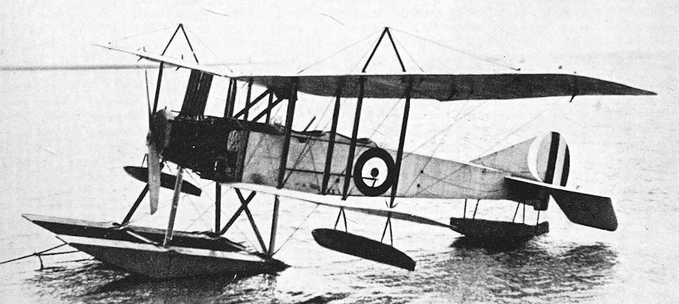
This photograph of the Avro 510 seaplane No. 133 was taken on October 11th, 1916.
One of the five production-type Avro 510s built for the R.N.A.S.
One of the five production-type Avro 510s built for the R.N.A.S.
Avro 521
THE Avro 521 was a derivative of the Avro 504, and was intended to be a two-seat fighter. It bore a family likeness to its great progenitor, and was probably derived via a R.N.A.S. version of the 504 which had (or was to have) a 110 h.p. Clerget engine, an elongated vee-type undercarriage, and widely separated cockpits. This machine existed at least as a design, and was to weigh 1,990 lb loaded; drawings show that it was designed to have the standard two-bay wings.
It is believed that the illustration shows the Avro 521. This aircraft had the same fuselage and vee-type undercarriage as the R.N.A.S. Clerget-powered two-seater mentioned above, but it was an R.F.C. type and therefore had no fin. The type of rudder which was used seemed to be identical to that of the Avro 504A, for the tail-skid was attached directly to it.
The wing structure was characterised by single-bay bracing and by the unusual arrangement of the centre-section struts. The wings were staggered, and ailerons were fitted to both upper and lower mainplanes.
The Avro 521 appeared early in 1916 and was tested by F. P. Raynham; it proved to be unpleasant to fly. The prototype crashed while being flown by a R.F.C. pilot some time later. An order was placed for twenty-five production machines, but it is doubtful whether any went further than training units. At least one was at Gosport in 1917 but crashed and killed its pilot, Captain Garnett.
SPECIFICATION
Manufacturers: A. V. Roe & Co., Ltd., Clifton. Street, Miles Platting, Manchester.
Power: 110 h.p. Clerget.
Service Use: Flown at Gosport.
Production: Twenty-six Avro 521s were built.
Serial Numbers: 1811, 7520-7544.

Avro 521
Avro 519
THE Avro 519 was a large and rather clumsy biplane which appeared to have the same wing structure as the Avro 510 seaplane. As on the Type 510, the 150 h.p. Sunbeam Nubian engine was fitted, but whereas the seaplane had a frontal radiator the Type 519 had a box-like radiator above and behind the engine.
The structure of the Avro 519 appeared to be quite conventional. The fuselage was characterised by an unusually deep top-decking, in addition to which the cockpits had peculiar windshield and head-rest fairings fitted fore and aft. A plain, sturdy vee undercarriage was used.
The tail unit incorporated a large fin of the shape associated with Avros built for the R.N.A.S. Prototypes were supplied to both the R.N.A.S. and R.F.C., however: four were ordered, the first two (8440 and 8441) going to the R.N.A.S., the second pair (1614 and 1615) to the R.F.C. The illustrations show No. 1614, which in May, 1916, was at Farnborough for tests. There it was known as “The Big Avro".
The aircraft’s designed purpose is uncertain, but it had the appearance of being intended for use as a bomber. Performance could not have been good on only 150 h.p., however, and the deep cockpit coamings would have made it difficult to use defensive armament effectively. The fate of the prototypes is not known, but the Type 519 was not developed.
SPECIFICATION
Manufacturers: A. V. Roe & Co., Ltd., Clifton Street, Miles Platting, Manchester.
Power: 150 h.p. Sunbeam Nubian.
Serial Numbers: 1614-1615; 8440-8441.
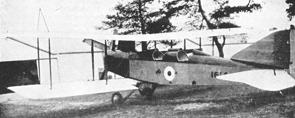
The Avro 519 No. 1614 at Farnborough, May, 1916, first of the two R.F.C. Avro 519A two seaters.
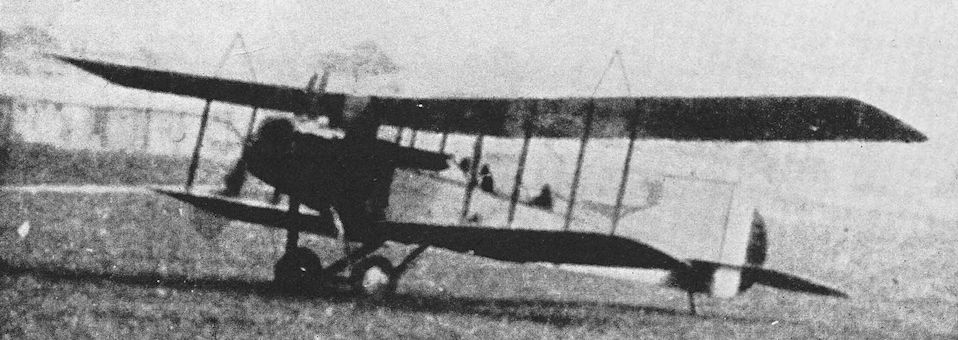
The Avro 519 No. 1614 at Farnborough, May, 1916.
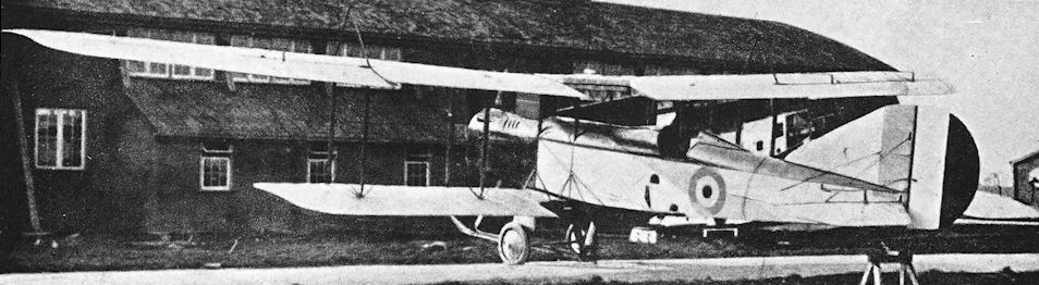
This photograph depicts No. 8441, second of the Avro 519s ordered for the Admiralty. This machine was a single-seater and had an undercarriage similar to that of the Avro 504. It will be seen that the wings were arranged to fold: the trailing portion of the centre-section has been folded forward to enable the mainplanes to be swung back.
Avro 527
THE Avro 527 was a two-seat biplane, powered by a 150 h.p. Sunbeam engine. It was built at the Manchester works of A. V. Roe & Co., and was contemporary with the Pike. It is believed that the Avro 527 was built for the R.F.C.
It is uncertain whether the aircraft illustrated was in fact the Avro 527 or merely a much-modified development of the Avro 504. It is known that it was not successful. The rate of climb was poor; the pilot’s forward view was obscured by the radiator; and neither the War Office nor the Admiralty could be convinced that the airframe was strong enough for the 150 h.p. engine. The type was not developed.

The precise identity of this Avro biplane is uncertain, but it may have been the Type 527
The Avro 527 with 150 h.p. Sunbeam engine was the final fighter derivative of the basic Avro 504.
The Avro 527 with 150 h.p. Sunbeam engine was the final fighter derivative of the basic Avro 504.
Avro 528
AS with the Avro 527, so with its successor the Type 528, only the fact of its existence has survived. It was powered by the 225 h.p. Sunbeam engine, and was ordered by the Admiralty. In the Avro works at Manchester the Type 528 followed the second, Green-powered, Pike.
AS with the Avro 527, so with its successor the Type 528, only the fact of its existence has survived. It was powered by the 225 h.p. Sunbeam engine, and was ordered by the Admiralty. In the Avro works at Manchester the Type 528 followed the second, Green-powered, Pike.
Avro 523, the Pike
THE Pike was the first twin-engined aeroplane to be built by the Avro company. The first machine was tested in May, 1916, and was powered by two Sunbeam engines, each of 160 h.p., which were installed as pushers. The airscrews were driven by extension shafts, and rotated in opposite directions. Wings and tailplane were simple rectangular surfaces with square extremities, and a balanced rudder of generous area was fitted to the large, low aspect-ratio single fin.
The aircraft had good lines and was of advanced conception for its day. Indeed, the basic proportions changed but little between the Pike and the Manchester of 1918, and the family likeness between the two types was pronounced.
The Pike was designed as a bomber, and had a good performance on only 320 h.p. It is not easy to find a reason why the type was not produced in quantity, but it is possible that the Short Bomber had been adopted as the standard R.N.A.S. bombing aircraft by the time the Pike appeared. The fact that the Short machine utilised a number of standard Short 184 components facilitated its production. Moreover, the Handley Page O/100 was in prospect, with the promise of weight-carrying capabilities much greater than those of the Pike.
The first Pike was sent to the R.N.A.S. Station at the Isle of Grain, where it was tested by F. P. Raynham. During an early flight, with R. H. Dobson (later Sir Roy Dobson) in the rear cockpit, the machine proved to be seriously tail-heavy, possibly due to an experimental distribution of loads. The Pike became sufficiently controllable to be landed only because Mr Dobson climbed along the fuselage to the bow cockpit, a performance which was fraught with danger. The transference forward of Dobson s weight enabled Raynham to throttle down the engines without stalling the aircraft, and a successful landing was made.
A second Avro 523 was tested in August, 1916, but differed in having two 150 h.p. Green engines which were installed as tractors. The Pikes were built at A. V. Roe’s Manchester works but were sent to the Hamble experimental works for completion.
SPECIFICATION
Manufacturers: A. V. Roe & Co., Ltd., Clifton Street, Miles Platting, Manchester; final assembly at Hamble works.
Power: Two 160 h.p. Sunbeam (pushers); two 150 h.p. Green (tractors).
Dimensions: Span: 60 ft. Length: 39 ft 1 in. Chord: 7 ft. Gap: 7 ft 3 in. Stagger: nil. Dihedral: 3 30'. Incidence: 4.
Areas: Wings: upper 418 sq ft, lower 397 sq ft, total 815 sq ft. Ailerons: each 30-5 sq ft, total 122 sq ft. Tailplane: 80 sq ft. Elevators: 45 sq ft. Fin: 17-5 sq ft. Rudder: 21 sq ft.
Weights: Empty: 4,000 lb. Loaded: 6,064 lb.
Performance: Maximum speed at ground level: 97 m.p.h.; at 10,000 ft: 88 m.p.h. Climb to 5,000 ft: 9 min 30 sec;
to 10,000 ft: 27 min. Endurance: 7 hours.
Armament: One Lewis machine-gun on rotatable ring-mounting on nose cockpit; a second Lewis gun on a similar mounting on rear cockpit aft of wings. Bombs could be carried.
Avro 529 and 529A
THE Avro 529 and 529A were ordered by the Admiralty in 1916, and were intended for service with the R.N.A.S. as long-range bombers. The type was developed from the earlier Pike and was of similar general layout, having three-bay wing bracing, a single fin and balanced rudder, and the simple but sturdy form of undercarriage first fitted to the Pike. The Type 529 was somewhat larger than its predecessor, however. Like the two Pikes, the 529 and 529A were made at Manchester and assembled at Hamble.
The basic design was a handsome twin-engined tractor biplane which, m its 529A form, had a remarkably good performance. By the time the Avro 529 appeared, the Handley Page O/100 was in service; and the prototype O/400 was flying a few weeks before the 529A was flown. No doubt it was considered undesirable to interfere with O/400 production. However that may be, the Avro design did not proceed beyond the prototype stage.
The 529 was first tested in April, 1917, but it was not until October of that year that the 529A appeared. The 529 and 529A differed principally in the type of engines fitted and in the arrangement of the fuel system. The 529 had two Rolls-Royce Falcon I engines developing 190 h.p. each, driving opposite-handed airscrews; the fuel was carried in a single large pressure tank immediately behind the pilot’s cockpit. The 529A had two 230 h.p. B.H.P. engines mounted directly on to the lower wings: the Falcons of the 529 were at the mid-gap position. The fuel system of the Avro 529A was designed to make each nacelle a self-contained unit: there was a 50-gallon tank in each nacelle, and from it fuel was pumped to a 10-gallon gravity tank directly above the engine. A small wind-driven pump was mounted on top of each nacelle. The two machines had slightly different elevator cable arrangements, and the 529A had a projecting bomb-aimer’s position under the nose. The wings could be folded.
Elevator control on the type was described as poor, and the ailerons were said to be rather heavy. The rudder must have been effective, however, for both the 529 and 529A could be flown straight with one engine out of action. An unusual feature in a machine of this size was the dual control which was installed in the rear gunner’s cockpit. The bombs were carried internally, suspended by their noses, and were aimed and released by the bow gunner, who could communicate with the pilot by means of a speaking tube.
SPECIFICATION
Manufacturers: A. V. Roe & Co., Ltd., Clifton Street, Miles Platting, Manchester; final assembly at Hamble works.
Power: Avro 529: two 190 h.p. Rolls-Royce Falcons, engines Nos. 1/190/201 (port) and 1/190/8 (starboard). Avro 529A: two 230 h.p. B.H.P. (Galloway-built), engines Nos. £15435 and £15442. Dimensions: Span: 63 ft. Length: 39 ft 8 in. Height: 13 ft. Chord: 7 ft 6 in. Gap: 7 ft 3 in. Stagger: nil. Dihedral: 3. Incidence: 3. Span of tail: 18 ft. Wheel track: 12 ft 9 in. Tyres: 900 X 200 mm. Airscrew diameter (Avro 529): 9 ft 11 1/2 in.
Areas: Wings: 922-5 sq ft. Ailerons: each 32-2 sq ft, total 128-8 sq ft. Tailplane: 48-4 sq ft. Elevators: 36-8 sq ft. Fin: 10 sq ft. Rudder: 24-5 sq ft.
Weights (lb) and Performance without Bombs:
Avro 529 Avro 529A
No. of Trial Report M.110 M.155
Date of Trial Report June, 1917 November, 1917
Type of airscrew used on trial A. V. Roe, 4834 and 4824 -
Weight empty 4.376 -
Military load 273 273
Crew 540 540
Fuel and oil 1,120 -
Loaded 6,309 6,323
Maximum speed (m.p.h.) at
8,000 ft 94 -
10,000 ft 89 106
13,000 ft 81-5 -
14,000 ft 79'5 -
15,000 ft - 93
m. s. m. s.
Climb to
1,000 ft 1 25 - -
6,500 ft 11 25 9 50
10,000 ft 21 40 17 20
12,000 ft 31 05 - -
14,000 ft 48 05 - -
15,000 ft - - 35 05
Service ceiling (feet) 13,500 17,500
Endurance (hours) 5 5
Tankage :
Petrol 140 gallons in pres- Main:
sure tank in 2 X 50 gallons
fuselage Service:
2x10 gallons Total: 120 gallons
Oil 7 gallons per engine; -
total 14 gallons
Water 8 gallons per engine; -
total 16 gallons
Armament: One Lewis machine-gun on a Scarff ring-mounting on front cockpit; a second Lewis gun on a Scarff ring-mounting was fitted to the cockpit aft of the wings. The bomb load of the Avro 529A could consist of twenty 50-lb bombs stowed internally within the fuselage, between the spars of the lower wing. The bombs were suspended by their noses.
Serial Numbers: Avro 529: 3694. Avro 529A: 3695. Both machines were built under Contract No. C.P. 122495/16/X/23723.
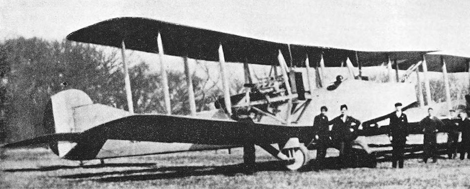
Avro Pike. The first Pike with two pusher Sunbeam engines.
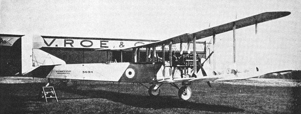
3694, the sole Avro 529, at Hamble in April 1917.

Avro 529A
Avro 530
THE Avro 530 was one of the many promising designs of the war period which, for one reason or another, did not go into production. It was a two-seat fighter of advanced conception, and its performance compared quite well with that of early versions of the Bristol Fighter. However, by the time the Avro 530 appeared in July, 1917, the Bristol machine was already in production; moreover, at that time virtually all Hispano-Suiza engines were absorbed by the S.E.5a production programme.
The Avro 530 was originally designed to have a 300 h.p. Hispano-Suiza engine but none was available at the time of completion of the airframe, and the prototype was fitted with the 200 h.p. Hispano-Suiza and the Sunbeam Arab. The components were made at the Manchester works of the Avro company and were sent to Hamble for assembly.
The machine was characterised by commendably clean design. The Hispano-Suiza version had a large open-fronted spinner on the airscrew, and the radiator was installed behind it within the engine cowling. The deep fuselage completely filled the gap between the wings, and the central connexion between the fuselage and upper wing had a plywood fairing which also housed the pilot’s machine-gun. The upper wing was level with the pilot’s eyes, and he therefore had an excellent view all round the upper hemisphere. The observer’s cockpit was immediately behind the pilot’s in order to ensure maximum crew cooperation. The undercarriage legs, which were normal vees, were carefully faired over with fabric.
The basic structure was conventional. The fuselage was the usual wire-braced wooden box-girder and had fairings on the sides. The engine was mounted on duralumin girders. The wings were made almost wholly of wood, but some metal was used in the construction of the ribs.
The wings were of R.A.F. 14 section, and were fitted with trailing-edge flaps along the whole of their length between the ailerons and the fuselage: these flaps were actuated by a wheel control in the pilot’s cockpit. For comparative tests a second set of wings of R.A.F. 15 section were built without flaps.
The version of the Avro 530 which had the Sunbeam Arab engine had no spinner; the undercarriage vees were much wider than those of the Hispano-powered version and were not faired over.
SPECIFICATION
Manufacturers: A. V. Roe & Co., Ltd., Clifton Street, Miles Platting, Manchester; final assembly at Hamble works.
Power: 200 h.p. Hispano-Suiza, engine No. 115034; 200 h.p. Sunbeam Arab.
Dimensions: Span: 36 ft. Length: 28 ft 6 in. Height: 9 ft 7 in. Chord: 5 ft 6 in. Gap: 5 ft. Stagger: 1 ft 9in. Dihedral: 1° 30'. Incidence: 2°. Span of tail: 12 ft. Airscrew diameter: 9 ft 9 in.
Areas: Wings: 325-5 sq ft. Ailerons: each 14-5 sq ft, total 58 sq ft. Tailplane: 28-4 sq ft. Elevators: 22-8 sq ft. Fin: 4-5 sq ft. Rudder: 8-8 sq ft.
Weights: Empty: 1,695 Military load: 214 lb. Crew: 360 lb. Fuel and oil: 411 lb. Loaded: 2,680 lb.
Performance: Maximum speed at ground level: 114 m.p.h.; at 10,000 ft: 102 m.p.h. Climb to 5,000 ft: 6 min 30 sec; to 10,000 ft: 15 min; to 18,000 ft: 40 min. Ceiling: 18,000 ft. Endurance: 4 hours at 10,000 ft.
Tankage: Petrol: main tank 33 gallons, auxiliary 7 gallons; total 40 gallons.
Armament: One fixed Vickers machine-gun mounted in the central fairing on top of the fuselage, and synchronised to fire forward through the revolving airscrew; one Lewis machine-gun on Scarff ring-mounting on rear cockpit.
Production: One Avro 530 was built under Contract No. A.S.425/17/C.

Avro 530 with 200 h.p. Hispano-Suiza engine.
Avro 533, the Manchester
THE ultimate war-time expression of the Avro twin-engined bomber concept was given in the excellent Manchester design of 1918. Its descent from the Pike and the Avro 529 was clearly discernible, but the Manchester showed several structural and aerodynamic improvements over its predecessors. The fuselage was shorter and deeper, and provided better accommodation for the crew of three; the arrangement of the interplane struts was simplified; and the tail surfaces were of more pleasing outline. The ailerons were balanced in an unusual way. Instead of the more normal horn balance, each aileron had, mounted above and parallel to it, a small auxiliary aerofoil. Thus, any depression of an aileron increased the angle of attack of the small aerofoil and produced a balancing force; the opposite effect was obtained on a raised aileron. Construction of the Manchester was undertaken at the Avro company’s Hamble works.
The Manchester was first designed early in 1918, at a time when great hopes were entertained for the A.B.C. Dragonfly radial engine, which was then going into production. The Manchester was therefore designed to have two Dragonflies, but as the aircraft neared completion it became evident that no engines were going to be available in time. To permit flight trials of the airframe, the first Manchester was modified to have Siddeley Puma engines and was designated the Avro 533A Manchester Mark II.
The engines were two high-compression Pumas which delivered 300 h.p. each, and with them the Manchester II was tested in December, 1918. Dragonfly engines ultimately became available, and a true Manchester Mk. I was completed with two Dragonflies. This chain of circumstances accounts for the fact that the Mk. II had the earlier serial number F.3492, whilst the Mk. I was F.3493. The tail-unit of the Manchester Mk. I differed from that of the Mk. II. The area of all tail surfaces was appreciably increased in the Mk. I; the fin and rudder were taller; and the Mk. I had plain elevators whereas those of the Mk. II had inset horn balances. Both machines had balanced rudders. A third version was projected with twin Liberty engines but was never built. The third Manchester airframe was, however, completed.
The Manchester appeared too late to go into production, but the performance of both Marks compared favourably with that of the more powerful D.H.10A, and bore testimony to the excellence of the design.
SPECIFICATION
Manufacturers: A. V. Roe & Co., Ltd., Hamble.
Power: Manchester Mk. I: two 320 h.p. A.B.C. Dragonfly I. Manchester Mk. II: two 300 h.p. Siddeley Puma (high compression). Manchester Mk. Ill: two 400 h.p. Liberty (projected).
Dimensions: Span: 60 ft. Length: 37 ft. Height: 12 ft 6 in. Chord: 7 ft 6 in. Gap: 7 ft 3 in. Stagger: nil. Dihedral: 2° 30'. Incidence: 40. Span of tail: 13 ft. Airscrew diameter: 2-9 metres.
Areas: Wings: upper 430 sq ft; lower (Mk. I) 383 sq ft, (Mk. II) 387 sq ft: total (Mk. I) 813 sq ft, (Mk. II) 817 sq ft. Ailerons: each 31 sq ft, total 124 sq ft. Tailplane: (Mk. I) 69 sq ft, (Mk. II) 50 sq ft. Elevators: (Mk. I) 38 sq ft, (Mk. II) 35 sq ft. Fin: (Mk. I) 16 sq ft, (Mk. II) 12 sq ft. Rudder: (Mk. I) 18 sq ft, (Mk. II) 16 sq ft.
Weights {lb) and Performance:
Manchester Mk. I Manchester Mk. II
No. of Trial Report M.266 -
Date of Trial Report October, 1919 -
Weight empty 4,887 4’574
Military load 433 1,074
Crew 540 540
Fuel and oil 1,530 970
Weight loaded 7,390 7,158
Maximum speed (m.p.h.) at
ground level - 125
6,500 ft 114-5 -
10,000 ft 112 119
15,000 ft 103-5 112-5
m. s. m. s.
Climb to
5,000 ft - - 6 30
6,500 ft 8 20 - -
10,000 ft 14 20 16 30
15,000 ft 28 00 32 00
17,000 ft - - 43 00
Service ceiling (feet) 19,000 17,000
Endurance at 10,000 ft (hours) 5 3/4 3 3/4
Tankage: Petrol (gallons) 183 116
Armament: Bomb load: 880 lb. One Lewis machine-gun on ScarfF ring-mounting on bow cockpit, one Lewis gun on similar mounting on rear cockpit aft of wings.
Production: Three prototypes were built at Hamble.
Serial Numbers: F.3492-F.3494 (F.3492 was the Manchester Mk. II, F.3493 was the Mk. I).

Avro Manchester Mk.I with A.B.C. Dragonfly engines.

Avro Manchester Mk.II with Siddeley Puma engines.
Avro 531, the Spider
THE Avro Spider appeared in April, 1918. It was a compact little single-seat fighter in which numbers of Avro 504K components were used in order to ensure rapid and easy production. In fact, the complete front portion of the fuselage was identical to that of the 504K, and many of the small fittings were standard 504K components.
The wing bracing was quite unlike anything used on any other contemporary British aeroplane. There were neither flying nor landing wires, but the structure was braced by a triangulated system of faired steel tubes. The lower wing was shorter than the upper, and was of unusually narrow chord: in this respect the wing arrangement resembled that of the Nieuport Scouts, and the lower wing seemed to be little more than part of the bracing for the upper mainplane. Spars were built-up spruce components, and the fuselage longerons and spacers were also spruce; the petrol tank was situated behind the cockpit. The undercarriage was a simple vee structure of faired steel tubes.
Particular attention had been paid to achieving the best possible view for the pilot. To this end the upper wing was mounted very close to the fuselage, and a circular hole was cut in the centre-section: through this hole the pilot’s head protruded. The mainplane was level with his eyes, so that his view of the upper hemisphere could not have been better; and the forward and downward view was helped by the short nose and narrow lower wing.
The Spider’s manoeuvrability was exemplary. During its trials it repeatedly outmanoeuvred contemporary standard scouts against which it was matched in mock combat. The Spider did not go into production, however, doubtless because of existing production programmes and the promise of other new types. It is also doubtful whether the fighter pilots of the Spider’s day would have welcomed a reversion to only one machine-gun as their armament.
As originally built, the Spider was powered by a 110 h.p. Le Rhone rotary engine, but it seems fairly certain (as the quoted performance figures show) that a 130 h.p. Clerget was also fitted. It would have been a simple matter to make such an engine-change, in view of the use of the 504K front fuselage. According to Jane's All the World's Aircraft, 1919 edition, it was intended to fit later Spiders with the Bentley B.R.2 engine, but the estimated performance figures quoted for that engine were apparently based on a power output of 180 h.p. whereas the B.R.2 delivered 238 h.p.
Another version of the design was given the Avro type number 531A, but it is uncertain whether the machine was ever completed. This variant was designed with normal biplane wings which had conventional interplane struts and wire bracing. The upper centre section was left completely open, as on the Sopwith Dolphin, but in the Avro 531A the pilot sat behind the rear spar instead of between the spars.
SPECIFICATION
Manufacturers: A. V. Roe & Co., Ltd., Clifton Street, Miles Platting, Manchester, and at Hamble.
Power: 110 h.p. Le Rhone; 130 h.p. Clerget.
Dimensions: Span: upper 28 ft 6 in., lower 21 ft 6 in. Length: 20 ft 6 in. Height: 7 ft 10 in. Chord: upper 6 ft, lower 2 ft 6in. Gap: 4 ft 2 1/2 in. Stagger: 2 ft. Dihedral: nil. Incidence: nil. Span of tail: 8 ft 6 in. Chord of tailplane: 2 ft 8 in. Chord of elevators: 1 ft 6 in. Tyres: 700 X 78 mm.
Areas: Wings: upper 144 sq ft, lower 45 sq ft, total 189 sq ft. Ailerons: each 11 sq ft, total 22 sq ft. Tailplane: 17-5 sq ft. Elevators: 11 sq ft. Rudder: 7-8 sq ft.
Weights (lb) and Performance:
130 h.p. Clerget Estimated figures for Bentley B.R.2
Weight empty 963 1,148
Military load 125 158
Pilot 180 180
Fuel and oil 249 248
Weight loaded 1,517 1,734
Maximum speed (m.p.h.)
at ground level 120 124
8,000 ft - 121
10,000 ft I 10 122
15,000 ft - i<5
m. s. m. s.
Climb to
3,500 ft - - 2 12
5,000 ft 4 00 - -
8,000 ft - - 5 00
10,000 ft 9 30 7 00
15,000 ft 22 00 13 30
18,000 ft - - 20 00
20,000 ft - - 26 00
Ceiling (feet) 19,000 -
Endurance at
10,000 ft (hours) - 2
15,000 ft (hours) - 2 1/2
Tankage: Petrol: 26 1/2 gallons. Oil: 6 gallons.
Armament: One fixed Vickers machine-gun mounted on top of cowling to starboard of centre, synchronised to fire forward through the revolving airscrew; 800 rounds of ammunition were carried.
SPECIFICATION OF AVRO 521A
Power: 130 h.p. Clerget.
Dimensions: Span: upper 28 ft, lower 27 ft. Length: 20 ft 6 in. Chord: 4 ft 6 in. Gap: 4 ft 3in. Stagger Dihedral: 2. Incidence: 1 30'.
Areas: Wings: upper 106 sq ft, lower 104 sq ft, total 210 sq ft. Ailerons: each 7-3 sq ft, total 29-2 sq ft. Tailplane: 17.5 sq ft. Elevators: 11 sq ft. Rudder: 7-8 sq ft.
Weights: Empty: 960 lb. Loaded: 1,514 lb.
Performance: Maximum speed at ground level: 120 m.p.h.; at 10,000 ft: 110-5 m.p.h.; at 15,000 ft: 103 m.p.h. Climb to 5,000 ft: 4 min; to 10,000 ft: 9 min 30 sec; to 15,000 ft: 22 min. Ceiling: 19,000 ft. Endurance: 3 hours.
Serial Numbers: It is believed that the serial numbers B.3952-B.3953 were allotted for Avro Spiders.
B.A.T. F.K.22 and F.K.23 Bantam
THE British Aerial Transport Co. was founded in 1917 by Samuel (later Lord) Waring, and the new concern took over premises in Hythe Road, Willesden, previously occupied by the Joucques Aviation Co. The firm’s chief designer was Frederick Koolhoven, who had left Sir W. G. Armstrong, Whitworth & Co., Ltd., to join the B.A.T. Co.; and the first aircraft built to his design by his new firm was the F.K. 22, a small single-seat fighter which was appropriately named the Bat.
The F.K.22 embodied some features which became characteristic of the Koolhoven-designed B.A.T. types, but which were regarded as unconventional in Britain. The fuselage was a wooden monocoque and the fin was built integral with it; the birch three-ply skin was applied to ash formers, and the cross-section was a near-ellipse. The pilot sat with his head protruding through a circular hole in the upper centre-section, which was attached directly to the fuselage. Each wing was made in three parts, all approximately equal in length. The spars were of spruce, and the underside of the lower centre-section was covered with birch three-ply. Only the outer panels of the mainplanes had dihedral, and ailerons were fitted to both upper and lower wings. Wooden interplane struts were used.
The undercarriage was of the divided-axle type which was used on all subsequent B.A.T. types of the war period: in the F.K. 22 it occupied the complete width of the lower centre-section. The vees were built up of seven laminations of spruce, and incorporated vertical coil springs for shock absorbers. The undercarriage therefore had a wide track and independently sprung wheels. The rudder had a horn balance.
The power unit for which the F.K. 22 was designed was the 120 h.p. A.B.C. Mosquito. This was a six-cylinder air-cooled radial engine. Unfortunately for the B.A.T. F.K. 22, the Mosquito proved to be unsuccessful in its bench tests.
It seems that, about the time when the F.K.22 airframe was complete and the failure of the A.B.C. Mosquito was known, it was decided to modify the design to take a later and more powerful A.B.C. radial engine which had appeared. This engine was the Wasp, a seven-cylinder radial of 170 h.p. The modified aircraft was renamed the Bantam. The A.B.C. Wasp was designed by Granville Bradshaw and was submitted to the Government in October, 1917. The engine was designed for ease of production, and performed quite well on its early trials, for it gave 170 h.p. for a weight of only 290 lb. Its early success (although enough to encourage its designer to press his newer design, the Dragonfly, upon the Government) was not continued.
However, the original F.K.22 airframe was flown, powered by rotary engines. Fitted with a 100 h.p. Gnome Monosoupape, an F.K.22 was tested at Martlesham Heath in February, 1918, and the machine numbered B.9945 was also flown with a 110 h.p. Le Rhone. Official documents refer to the Gnome-powered version as the Bantam Mark II, presumably on the analogy of such designations as the Avro Manchester Mk. II and Sopwith Cobham Mk. II. The designation Bantam Mk. I was applied to the Wasp-powered machine.
The analogy was not complete, however, for the relationship between Bantams Mk. II and Mk. I was much less close than the relationship between the corresponding marks of Manchester and Cobham. The Bantam Mk. I was in fact a new design and was given a new type number, F.K.23, by its designer. When the first Bantam Mk. I appeared, it differed markedly in appearance from the F.K.22 as exemplified by B.9945.
The new machine was considerably smaller than the F.K.22, and the wing area was greatly reduced. Again the upper wing was attached directly to the fuselage and there was a hole for the pilot’s head and shoulders, but the wing was made in one piece and was quite flat. The lower wings alone had dihedral and were attached to a centre-section of short span. As on the F.K.22, wooden interplane struts were fitted. The vee-struts of the undercarriage were directly under the inner interplane struts.
A monocoque fuselage of new design and good aerodynamic form was used. Its basic structure consisted of four ash longerons bearing spruce formers round which sheets of plywood were wrapped. The low aspect-ratio triangular fin was built integral with the fuselage, and the rudder was a plain surface with a straight vertical trailing edge.
The monocoque fuselage was officially viewed with some suspicion. Although many contemporary German aeroplanes had fuselages built on that principle, the idea was still regarded as somewhat revolutionary in Britain at the time of the Bantam’s appearance.
The Bantam B.9947 was at Hendon in February, 1918. Unfortunately, the type proved to have disastrous spinning characteristics. The gap was narrow because the upper wing had been placed on top of the fuselage in order to give the pilot the best possible view; there was no stagger; the centre of gravity was rather far aft; and the stubby little fuselage gave a comparatively short moment arm for the fin and rudder.
The Bantam’s spin began at a normal speed but rapidly accelerated until it reached a phenomenal rate of autorotation, from which it could be brought out only by vigorous use of the controls. Accidents occurred with Bantams owing to their spinning characteristics. Major Christopher Draper, one of the most noted exponents of the type, spun into the ground at Hendon in one of the prototypes. He survived the crash, thanks to the great strength of the Bantam’s fuselage, which came out of the crash remarkably well.
After a second accident had occurred in which a Bantam had spun into the ground, the Accidents Investigation Sub-committee of the Aeronautical Research Committee requested that experiments be conducted to determine the cause of the crashes. It was shown that the Bantam’s unusual behaviour in a spin was attributable chiefly to the position of the centre of gravity which, at 42 per cent chord, was too far aft; and to the combination of zero stagger with an unusually small gap/chord ratio (0,81).
However, the Bantam was fast and highly manoeuvrable, and a small production batch was ordered. The production machines had a re-designed wing structure and a revised tail-unit: enlarged horizontal surfaces were fitted, the rudder was increased in area, and there was a corresponding reduction in the area of the fin. The new wings were of greater span and area, and both were given equal dihedral angles. The interplane struts were of steel tube. This version, which was the best-known form of the design, had the same type number F.K.23.
These modifications did much to cure the trouble, and the Bantam did well in all its Service trials. Only nine production Bantams, numbered F.1653 to F. 1661, were built, however. The A.B.G. Wasp was noted for its capricious behaviour, and it was decided not to proceed further with the production of that engine. Deprived of its power unit, the Bantam had perforce to be withdrawn from production also.
A single Bantam fuselage was built for the Admiralty and was exposed for several months on Inverkeithing Dock to test its resistance to widely varying climatic conditions. When returned to the works for inspection the fuselage was found to have suffered very little deterioration.
Shortly after the war, Lord Waring felt obliged to reduce his aviation interests and the B.A.T. company was virtually disbanded, although technically it was amalgamated with the Alliance Aeroplane Co., Ltd., of Acton, and the British Nieuport & General Aircraft Co., Ltd., of Cricklewood, two other concerns which had been founded by Lord Waring.
In the meantime, one of the Bantams had been fitted with the more powerful A.B.C. Wasp II, which delivered 200 h.p. After the merger of the firms, this machine was put through a series of trials by Captain L. R. Tait-Cox, the Nieuport test pilot. The top speed was increased to 146 m.p.h. at 10,000 feet, and the rate of climb was correspondingly improved.
At least one Bantam went to America, where it was flown at Wright Field with American markings. Its American serial number was A.S.94111, and it bore the Wright Field Project Number P.167 on the rudder.
Seven Bantams went on to the British Civil Register after the Armistice. They were registered K.123 (later G-EACN), K.125 (G-EACP), K.154 (G-EAFM), K.155 (G-EAFN), G-EAJW, G-EAMM and G-EAYA. K.123 and K.125 were entered in the 1919 Aerial Derby, in which they were flown by Clifford Prodger and Major Draper. K.125 had its lower wing clipped just outboard of the inner bay of interplane struts, the extensions of the upper mainplane being braced by long struts.
In 1924 G-EAYA (formerly F.1661) was bought by Frederick Koolhoven and was taken by him to Holland. There it was fitted with a 200 h.p. Armstrong Siddeley Lynx engine, and was said to have attained a speed of 246 km/hr (about 154 m.p.h.).
SPECIFICATION
Dimensions:
Bantam Mk. II (Gnome) Bantam Mk. I prototype Production
Bantam
Span 24 ft 8 in. 20 ft 25 ft
Length 20 ft 8 in. - 18 ft 5 in.
Height 7 ft 5 in. - 6 ft 9 in.
Chord 4 ft 11 in. 4 ft 3 ft 11 1/4 in.
Gap 4 ft 3 in. 3ft 3ft 3 1/2 in
Stagger Nil Nil Nil
Dihedral, upper 2° Nil 2° 30'
Dihedral, lower 2° 2° 2° 30'
Incidence, upper 2° 2° -
Incidence, lower 2° 2° -
Span of tail 6 ft 6 in. 6 ft 7 in. 9 ft 2 in.
Wheel track - - 7 ft 2 1/2 in.
Airscrew diameter - - 7 ft 10 1/2 in.
Areas (sq ft):
Wings 230 160 185
Ailerons: each 6 3-8 4-5
total 24 15-2 18
Tailplane 7 10-4 16-7
Elevators 10-5 5-85 6-3
Fin 2-5 3-5 2-85
Rudder 6 3-85 4-4
Weights (lb) and Performance:
Bantam Mk. II (Gnome) Bantam Mk. I (production)
Wasp I Wasp II
No. of Trial Report M.175 M.242 -
Date of Trial Report February, 1918 October, 1918 -
Type of airscrew used on trial P.3012 I.P.C.2414 -
Weight empty 866 833 -
Military load 50 130 -
Pilot 180 180 -
Fuel and oil 164 178 -
Weight loaded 1,260 1,321 -
Maximum speed (m.p.h.) at
6,500 ft - 128 -
10,000 ft 100 125-5 146
15,000 ft - 118 -
m. s. m. s. m. s.
Climb to
6,500 ft 9 05 5 10 - -
10,000 ft 16 50 9 00 - -
15,000 ft 43 00 17 05 - -
17,000 ft - - - - 16 00
Service ceiling (feet) 14,500 20,000 -
Endurance (hours) - 2 1/4 -
Tankage: Petrol (gallons) 17 22 -
Manufacturers: The British Aerial Transport Co., Ltd., Hythe Road, Willesden, London, N.W.
Power: Bantam Mk. I: 170 h.p. A.B.C. Wasp I; 200 h.p. A.B.C. Wasp II. Bantam Mk. II: 100 h.p. Gnome Monosoupape; 110 h.p. Le Rhone.
Armament: Two fixed Vickers machine-guns mounted low down on either side of the fuselage, firing between the lowest pair of cylinders on each side, and synchronised to fire forward through the revolving airscrew (i.e., on production Bantams).
Service Use: Only one B.A.T. aeroplane was delivered to a Training Unit during 1918. In February, 1918, the Bantam Mk. II, B.9945 was at Hounslow, and the Mk. I prototype, B.9947 was at Hendon. On October 31st, 1918, the R.A.F. had three unspecified B.A.T.s on charge: one was at an Aircraft Acceptance Park and two were at testing units. One production Bantam Mk. I went to America.
Serial Numbers: B.9944-B.9949: ordered under Contract No. A.S.25314. F.1653-F.1661.

B.A.T. Bantam Mk.II with 110 h.p. Le Rhone engine. This aeroplane was the F.K.22 design.

Bantam Mk.II

B.A.T. Bantam, B.9947. Original form of Bantam Mk.I with engine removed. The flat top wing can be seen.

B.A.T. Bantam F.1653 with modified engine installation.

Production Bantam Mk.I with enlarged wings having equal dihedral, steel-tube interplane struts, and modified tail-unit.
This BAT FK 23 Bantam, serial no F 1655, the third of nine production aircraft completed, proclaims its British Aerial Transport parentage in bold white lettering down its fuselage in place of the normal roundel, indicating that this photograph dates from after the war and that this was one of the machines sold as war surplus in 1919. The history of the Bantam is convoluted and starts in mid-1917 when Frederick Koolhoven left Armstrong Whitworth to join the newly formed Willesden-based BAT, taking his tell-tale FK design numbers with him. At BAT Koolhoven's first task centred on designing a company-funded single seat fighter venture, designated FK 22. First flown in the early autumn of 1917 this machine gained Air Board interest and a contract for six examples followed. Originally planned to use a 120hp ABC Mosquito radial, one of the four FK 22s known to have been built and flown during 1918 used a 100 hp Gnome Monosoupape, subsequently replaced by a 110hp Le Rhone 9J rotary. To compound matters, virtually all of the FK 22s varied in airframe detail, but out of this melee emerged the 170hp ABC Wasp powered example in the spring of 1918, the change being considered great enough to warrant the new designation of FK 23 Bantam. Others of the original FK 22 were re-engined with the Wasp, but all of these machines were criticised for the ease with which they would enter a vicious, flat or autorotative spin. To cure this problem, the later nine so-called production aircraft incorporated a modified set of increased span wings and tail unit. The later FK 23s that initially appeared in October 1918 had the by now standard twin Vickers guns, along with a top level speed of 128mph at 6,500 feet, falling to 118mph at 18,000 feet. Time to reach 10.000 feet took 9 minutes. Time, however, was about to run out on the Bantam with the coming of the Armistice.
This BAT FK 23 Bantam, serial no F 1655, the third of nine production aircraft completed, proclaims its British Aerial Transport parentage in bold white lettering down its fuselage in place of the normal roundel, indicating that this photograph dates from after the war and that this was one of the machines sold as war surplus in 1919. The history of the Bantam is convoluted and starts in mid-1917 when Frederick Koolhoven left Armstrong Whitworth to join the newly formed Willesden-based BAT, taking his tell-tale FK design numbers with him. At BAT Koolhoven's first task centred on designing a company-funded single seat fighter venture, designated FK 22. First flown in the early autumn of 1917 this machine gained Air Board interest and a contract for six examples followed. Originally planned to use a 120hp ABC Mosquito radial, one of the four FK 22s known to have been built and flown during 1918 used a 100 hp Gnome Monosoupape, subsequently replaced by a 110hp Le Rhone 9J rotary. To compound matters, virtually all of the FK 22s varied in airframe detail, but out of this melee emerged the 170hp ABC Wasp powered example in the spring of 1918, the change being considered great enough to warrant the new designation of FK 23 Bantam. Others of the original FK 22 were re-engined with the Wasp, but all of these machines were criticised for the ease with which they would enter a vicious, flat or autorotative spin. To cure this problem, the later nine so-called production aircraft incorporated a modified set of increased span wings and tail unit. The later FK 23s that initially appeared in October 1918 had the by now standard twin Vickers guns, along with a top level speed of 128mph at 6,500 feet, falling to 118mph at 18,000 feet. Time to reach 10.000 feet took 9 minutes. Time, however, was about to run out on the Bantam with the coming of the Armistice.
B.A.T. F.K.24, Baboon
THE Baboon was a small two-seat training biplane, in the design of which Koolhoven had aimed at ease of production and interchangeability of components. The fuselage was a very simple box structure with a rounded top-decking which was the only concession to aesthetics or aerodynamics in the entire design. The fuselage was considerably strengthened by its plywood covering. The A.B.C. Wasp radial engine was mounted on the flat-nose bulkhead and was innocent of any pretence at fairing; the interplane and centre-section struts were plain steel tubes without fairings; and all flight surfaces were straight-edged and square-cut. The undercarriage was the same wide-track, split-axle type used on the Bantam.
Interchangeability of components was held to be a desirable feature of trainer aircraft, which could be expected to suffer more damage than other types. Koolhoven, with typical ingenuity, carried the idea almost to its extreme in the Baboon: not only were the upper and lower mainplanes interchangeable, but the ailerons, elevators and rudder were all identical surfaces.
The Baboon was not officially adopted, but survived the Armistice and went on the British Civil Register as G-EACO.
SPECIFICATION
Manufacturers: The British Aerial Transport Co., Ltd., Hythe Road, Willesden, London, N.W.
Power: 170 h.p. A.B.C. Wasp I.
Dimensions: Span: 25 ft. Length: 22 ft 8 in. Height: 8 ft 10 in. Chord: 5 ft yin. Gap: 4 ft 8 1/2 in. Stagger: nil. Dihedral: 2. Span of tail: 9 ft 10 in. Airscrew diameter: 7 ft 10 in.
Areas: Wings: 259 sq ft. Ailerons: each 6 sq ft, total 24 sq ft. Tailplane: 15-75 sq ft. Elevators: 12 sq ft. Fin: 5-25 sq ft. Rudder: 6 sq ft.
Weights: Empty: 950 lb. Disposable load: 400 lb.
Performance: Maximum speed at ground level: 90 m.p.h. Climb to 10,000 ft: 12 min. Endurance: 2 hours.
Tankage: Petrol: 12 gallons.
Armament: None.
Serial Numbers: D.9731-D.9736. It is believed that only D.9731 was built.

B.A.T. Baboon.
B.A.T. F.K.25, the Basilisk
THE stumpy little Basilisk was built in 1918. It was a single-seat fighter developed from the Bantam, and was fitted with the more powerful A.B.C. Dragonfly I radial engine of 320 h.p.
Once again Koolhoven produced a machine having a wooden monocoque fuselage, two-bay wings of equal span, and the typical wide-track undercarriage with independent springing of each wheel. In the Basilisk the wing and cockpit arrangements were more conventional than those of the Bantam. The upper wing was made in two halves which were connected to the fuselage by a single N-strut on the aircraft’s centre-line. The pilot sat behind and slightly below the upper wing. Only the lower wing was rigged with dihedral. On the first prototype, F.2906, plain ailerons were fitted to upper and lower wings, but the second Basilisk had horn-balanced ailerons. The later machine also had a larger fairing over the machineguns.
Some rather exaggerated claims have been made for the Basilisk’s performance, and figures quoting a speed of 162 m.p.h. at ground level have gained some credence. The performance details given below come from a Martlesham Heath test report dated October, 1919, and are probably much more realistic. It will be seen that the performance was still very good, however. The Basilisk suffered (as did so many of its contemporaries) from the shortcomings of its A.B.C. Dragonfly engine. The Dragonfly was developed from August, 1917, onwards, and seemed to hold such promise that large-scale production was ordered in 1918. It is therefore not surprising that so many prototype aircraft of that year were fitted with the Dragonfly. This engine is discussed in the history of the Nieuport Nighthawk.
One of the Basilisks crashed in 1919, killing its pilot, Peter Legh, who had been one of the B.A.T. team of test pilots.
SPECIFICATION
Manufacturers: The British Aerial Transport Co., Ltd., Hythe Road, Willesden, London, N.W.
Power: 320 h.p. A.B.C. Dragonfly I.
Dimensions: Span: 25 ft 4 in. Length: 20 ft 5 in. Height: 8 ft 2 in. Chord: 4 ft 6 1/2 in. Gap: 4 ft 4 in. Stagger: nil. Span of tail: 9 ft 10 in. Airscrew diameter: 8 ft 8 in.
Areas: Wings: 212 sq ft. Ailerons: each 7-5 sq ft, total 30 sq ft. Tailplane: 13-7 sq ft. Elevators: 8-3 sq ft. Fin: 2-6 sq ft. Rudder: 4-5 sq ft.
Weights and Performance: No. of Trial Report: M.267. Date of Trial Report: October, 1919. Type of airscrew used on trial: A.B.9331. Weight empty: 1,454 lb. Military load: 218 lb. Pilot: 180 lb. Fuel and oil: 330 lb. Weight loaded: 2,182 lb. Maximum speed at 6,500 ft: 142-5 m.p.h.; at 10,000 ft: 141 m.p.h.; at 15,000 ft: 135 m.p.h. Climb to 6,500 ft: 4 min 50 sec; to 10,000 ft: 8 min 25 sec; to 15,000 ft: 15 min 5 sec. Service ceiling: 22,500 ft. Endurance: 3 1/4 hours.
Tankage: Petrol: 40 gallons.
Armament: Two fixed and synchronised Vickers machine-guns mounted on top of the fuselage, firing forward. These guns were slightly staggered: the port gun was a few inches forward of the starboard.
Serial Numbers: F.2906-F.2908. At least two, F.2906 and F.2907, were built.

Опытный экземпляр истребителя "Бэзилиск"
Side View of the first B.A.T. Basilisk with plain ailerons (320 h.p. A.B.C. "Dragonfly" engine).
Side View of the first B.A.T. Basilisk with plain ailerons (320 h.p. A.B.C. "Dragonfly" engine).

B.A.T. Basilisk. The second Basilisk with horn-balanced ailerons.
Beardmore W.B.I
THE well-known engineering and ship-building firm of William Beardmore & Co. entered the aircraft industry shortly before the outbreak of war in 1914, when they obtained a licence to build the German D.F.W. biplane, which was to be powered by the Beardmore-built Austro-Daimler engine. As war came closer, Beardmores were among the first firms to be awarded contracts for the manufacture of the B.E.2c, and throughout the war large numbers of aircraft of various types were built at Dalmuir.
In September, 1914, G. Tilghman Richards went to Beardmores as a Lieutenant, R.N.V.R., attached to the R.N.A.S. He, in common with several others who had had some experience of aircraft construction, was commissioned and classed as one of H.M. Inspectors of Naval Aircraft when the outbreak of war stopped the production of non-military aircraft. Up till then Mr Richards had played a leading part in the development of the Lee-Richards Annular Monoplane.
In early 1916 the Admiralty began to encourage contracting firms to undertake original design work and, in the case of Beardmores, allowed Mr Richards to resign his commission in order to become the firm’s chief designer and assistant manager of their Aviation Department.
The first Beardmore aeroplane was designated W.B.I, and construction began in 1916. It was a large two-seat single-engined biplane, designed as a long-range bomber. It was intended to deliver surprise attacks by long glide approaches on to its targets, and to this end Mr Richards paid particular attention to endowing the W.B.I with the best possible gliding angle. The nose was carefully streamlined, the three-bay wings were of fairly high aspect-ratio and were heavily staggered; and despite its large side radiators and complex undercarriage the W.B.I’s gliding angle was about i in 15.
The observer acted as bomb-aimer. His cockpit was situated well aft and had an aperture in the floor, through which the bombs were sighted. A visual type of intercommunication equipment linked the observer and pilot: it was a two-way system not very different from a ship’s engine-room telegraph.
The W.B.I was delivered to the R.N.A.S. and was flown with both the 230 h.p. Beardmore Adriatic and 240 h.p. Sunbeam engines. By the time of its appearance, however, the Handley Page O/100 was becoming available and held out the promise of carrying greater bomb loads at comparable speeds. The W.B.I was not adopted for Service use.
The machine’s “quadricycle” undercarriage and clean design contributed to a crash when it was being flown by Wing-Commander R. E. C. Peirse at Cranwell in 1917: a*- the time the W.B.I had the Sunbeam engine. After landing well out on the aerodrome, the machine rolled on, tail up, and crashed into two B.E.2c’s parked on the tarmac. The B.E.2 suffered most of the resulting damage, but the W.B.I was not flown again at Cranwell.
A development with the 500 h.p. B.H.P. Atlantic engine was projected under the designation W.B.IA. In it the wing span was increased to 70 ft and the area to 946 sq ft; there were to be four bays of interplane struts. The pilot and observer were accommodated well aft: in fact, the fin blended with the fairing round the observer’s gun-ring. The estimated maximum speed at 10,000 ft and at a loaded weight of 8,900 lb was 101 m.p.h.
SPECIFICATION
Manufacturers: William Beardmore & Co., Ltd., Dalmuir, Dumbartonshire.
Power: 230 h.p. Beardmore (Galloway) Adriatic (the version of the 230 h.p. B.H.P. engine built by the Galloway Engineering Co.); or 240 h.p. Sunbeam.
Dimensions: Span: 61 ft 6 in. Length: 32 ft 10 in. Height: 14 ft 9 in. Chord: 7 ft. Gap: 7 ft. Span of tail: 18 ft. Airscrew diameter: 10 ft 6 in.
Areas: Wings: 796 sq ft. Ailerons: each 28-32 sq ft, total 113-28 sq ft. Tailplane: 66 sq ft. Elevators: 40 sq ft. Fin: 14-2 sq ft. Rudder: 20 sq ft.
Weights (Beardmore Engine): Weight empty: 3,410 lb. Disposable load: 1,100 lb. Fuel and oil: 1,090 lb. Weight loaded: 5,600 lb.
Performance (Beardmore Engine): Maximum speed at ground level: 91 m.p.h. Climb to 5,000 ft: 26 min; to 10,000 ft: 44 min. Endurance: 7-3 hours.
Tankage: Petrol: 137 gallons.
Armament: Six 110-lb bombs. Provision was made for the fitting of a ring-mounting on the rear cockpit for a free Lewis machine-gun.
Service Use: Flown experimentally at R.N.A.S. Station, Cranwell.
Serial Number: The official serial number N.525 was allotted to a Beardmore design which may have been the W.B.I.

The W.B.I as rebuilt without N-struts out. Note the ungainly undercarriage, ladder for entry on the port side, and radiators on the centre section struts and fuselage side.
Beardmore W.B.II
THE second Beardmore type designed by Tilghman Richards was developed by him from the B.E.2C, for which type Beardmores were contractors to the Admiralty. Mr Richards wanted to show what the design was capable of, given a more powerful engine and an aerodynamically clean fuselage. Official permission was given for the construction of a prototype, and the resulting aircraft was a marked improvement over the B.E.2C. It was named Beardmore W.B.II.
The only B.E. components which in fact were used were the mainplanes and interplane struts. The fuselage was faired to a circular cross-section, and the airscrew originally had a large open-fronted spinner. The engine was a 200 h.p. Hispano-Suiza. The clean lines of the fuselage were somewhat marred by the exhaust stacks and radiators: these were disposed in two elements mounted in an inverted vee just behind the forward cabane struts. Petrol was carried in two 21-gallon tanks installed behind the engine, and the oil tank was mounted externally below the engine.
The undercarriage had two half-axles pivoted Sopwith-fashion at the mid-point of the two steel spreader-bars which connected the two plain vee-struts. A four-bladed airscrew was used at first, but was later replaced by a two-blader.
The method of actuating the elevators was interesting and unusual at a time when the almost universal medium was wire cable. Control rods were used, and each elevator had one control horn only, on its lower surface.
Whereas the observer of the B.E.2c occupied the forward seat, the W.B.II accommodated him behind the pilot where he could make effective use of his gun. The observer’s gun-mounting on the W.B.II was designed by Mr Richards, and gave a greater field of fire than the then-standard Scarff ring-mounting. The Beardmore-Richards mounting consisted of a “witch’s broomstick” built up of channel-section duralumin, pivoting on a ball joint at the centre of the cockpit floor and with its upper end running round the ring which surmounted the cockpit. The gunner’s seat was fixed half-way up the “stick”, which could thus be swung round instinctively and easily, and was provided with an instantaneous lock. The upper end of the “stick” carried the gun-mounting proper, which had a further range of movement: it could be swung upwards to enable the gun to fire vertically, or outwards when, with the “stick” athwartships, a line of fire could be obtained fifteen degrees past the centre-line of the aircraft in a downwards direction. Thus the normal blind spot was virtually eliminated.
By December, 1917, several modifications had been made to the W.B.II. The engine was moved forward and the spinner discarded; the nose cowling was given a rounded contour. The gun-ring on the observer’s cockpit was raised 5 1/2 inches, which made it more comfortable and effective in use. Aluminium tanks replaced the original steel ones.
The W.B.II was tested at Port Victoria and at Martlesham Heath, and was well reported on. It was said to be manoeuvrable and easy to land.
The type did not go into production, but a development was projected with the 230 h.p. B.H.P. engine. This machine was designated W.B.IIA, and was to have been a fighter-reconnaissance two-seater with considerably increased fuel capacity. The speed was expected to be 125 m.p.h. at sea level and 117 m.p.h. at 10,000 feet.
A further development known as the WB.IIB was built as an air-mail transport. Two machines, registered G-EARX and G-EARY were built, and participated in the Air Ministry competition for civil aircraft, held at Martlesham Heath in August, 1920. The Beardmore company initiated a Renfrew-London air-mail service with these machines, but it was short-lived.
SPECIFICATION
Manufacturers: William Beardmore & Co., Ltd., Dalmuir, Dumbartonshire.
Power: 200 h.p. Hispano-Suiza, engine No. (Peugeot) 115014.
Dimensions: Span: 34 ft 10 in. Length: 26 ft 10 in. Height: 10 ft. Chord: 5 ft 6 in. Gap: 5 ft 6 in. Stagger: 2 ft. Dihedral: 1° 30'. Incidence: 1° 30'. Span of tail: 13 ft 6 in. Wheel track: 5 ft. Tyres: 750 X 125 mm. Airscrew diameter: 9 ft 6 1/2 in.
Areas: Wings: 354 sq ft. Ailerons: each 16 sq ft, total 64 sq ft. Tailplane: 27-5 sq ft. Elevators: 20-2 sq ft. Fin: 6 sq ft. Rudder: 11-5 sq ft.
Weights and Performance: Date of Trial Report: December, 1917. Type of airscrew used on trial: Lang 3500A, Series No. L/14104. Weight empty: 1,765 lb. Military load: 185 lb. Crew: 360 lb. Fuel and oil: 340 lb. Loaded: 2,650 lb. Maximum speed at ground level: 120 m.p.h.; at 10,000 ft: 111-5 m.p.h.; at 13,000 ft: 107 m.p.h. Climb to 1,000 ft: 1 min 15 sec; to 2,000 ft: 2 min. 35 sec; to 5,000 ft: 7 min; to 8,000 ft: 12 min 30 sec; to 10,000 ft: 14 min 40 sec; to 12,000 ft: 22 min 40 sec; to 13,000 ft: 26 min 10 sec; to 14,000 ft: 30 min 10 sec. Service ceiling: 17,000 ft. Endurance: 2,8 hours.
Tankage: Petrol: 42 gallons. Oil: 4 1/2 gallons. Water: 8 gallons.
Armament: Two fixed, synchronised Vickers machine-guns firing forward. One free Lewis machine-gun on Beardmore-Richards mounting in rear cockpit.
Production: One prototype was built under Contract No. A.S.2864/18.

The W.B.II as originally rolled out at Dulmuir with large spinner and low-sided rear cockpit. Note the windows to give light to the pilot's cockpit. The rear gunner has ducked down in his cockpit in order to show how he can employ his Lewis gun vertically upwards.

The background has been severely removed from this photograph of the W.B.II in its final form. The built-up rear cockpit and the new nose contour without the spinner are noteworthy. The Beardmore-Richards gun mounting is clearly visible.
Beardmore W.B.III (S.B.3D)
BEARDMORES were the first manufacturers to build the Sopwith Pup under licence. The earliest production Pups were built under Admiralty contracts for delivery to the R.N.A.S., and soon proved their worth in action.
In February, 1917, the Grand Fleet Aircraft Committee recommended that the Sopwith Baby seaplanes carried by H.M.S. Campania should be replaced by Pups. A few Pups were sent to the ship for experimental work, and from that time onwards Pups were flown from various types of warship.
With the initiation of shipboard flying, attention was at once focused on the desirability of saving stowage space on board ship. Beardmores therefore undertook the task of redesigning the Pup so that it would fold up, and so thorough was the reconstruction of the aeroplane that not only did the wings fold, but the undercarriage could also be “retracted” into the bottom of the fuselage; it was, however, a normal vee type when extended. In the event of an emergency landing at sea, the complete undercarriage could be jettisoned. Emergency flotation gear was fitted.
The modified machine bore the Beardmore type number W.B.III. The most noticeable difference between the Pup and the W.B.III was that the wings of the latter had no stagger and reduced dihedral. Instead of the normal centre-section struts of the Pup, the W.B.III had four full-length interplane struts connecting the upper and lower centre-sections: these struts were joined to the upper longerons by transverse struts.
The prototype W.B.III was a converted Pup which had the official serial number 9950: it was the last machine of a batch of fifty Pups which were built by Beardmores for the Admiralty. On the prototype, interplane struts were fitted at the inboard ends of the wings; they preserved the bracing truss when the wings were folded. The ailerons were actuated by a system of control rods: upright rods from the cockpit were attached to bell-cranks in the upper centre-section, and the cranks moved long horizontal rods running along the rear spar of the upper wings. Upper and lower ailerons were linked by light struts. Skids were fitted under the lower wing-tips, and could be folded up against the underside of the wings. The W.B.Ill’s fuselage was about a foot longer than that of the Pup.
Production was undertaken on a modest scale. The early production W.B.Ills resembled the prototype, having the additional interplane struts at the inboard ends of the wings and the rod-operated ailerons. Later aircraft had only a cable connecting the inboard ends of the upper and lower mainplanes, the wingtip skids were discarded, and a simpler and more conventional cable-operated aileron control system was fitted. The standard engine was the 80 h.p. Le Rhone, but some machines may have had the 80 h.p. Clerget.
There are indications that two different forms of undercarriage may have been fitted; one capable of being jettisoned only, the other capable only of folding. The official designation S.B.3D was applied to the former version of the W.B.Ill, the suffix D denoting “Dropping undercarriage”; the second form was known as the S.B.3F, the F signifying “Folding undercarriage”.
The W.B.Ill saw service as part of the equipment of some of the early aircraft carriers: at one time H.M.S. Furious had as many as fourteen W.B.IIIs. According to Jane’s All the World’s Aircraft, 1920 edition, Japan had a few on the strength of her Naval Air Service.
SPECIFICATION
Manufacturers: William Beardmore & Co., Ltd., Dalmuir, Dumbartonshire.
Power: 80 h.p. Le Rhone 9C; 80 h.p. Clerget.
Dimensions: Span: 25 ft. Length: 20 ft 2 1/2 in. Height: 8 ft 1 1/4 in. Chord: 5 ft 1 1/2 in. Gap: 4 ft 9in. Stagger: nil. Span of tail: 10 ft 1 in. Airscrew diameter: 8 ft 6 in.
Areas: Wings: 243 sq ft. Ailerons: each 5-75 sq ft, total 23 sq ft. Tailplane: 23 sq ft. Elevators: 11-5 sq ft. Fin: 3-5 sq ft. Rudder: 4-5 sq ft.
Weights: Empty: 890 lb. Military load: 55 lb. Pilot: 180 lb. Fuel and oil: 164 lb. Weight loaded: 1,289 lb.
Performance: Date of Trial Report: January 12 th, 1918. Maximum speed at ground level: 103 m.p.h.; at 6,500 ft: 98 m.p.h.; at 10,000 ft: 91 m.p.h. Climb to 5,000 ft: 9 min; to 6,500 ft: 12 min 10 sec; to 10,000 ft: 24 min 20 sec. Service ceiling: 12,400 ft. Endurance: 2 3/4 hours.
Tankage: Petrol: 18 gallons.
Armament: The prototype had a vertically-mounted Lewis machine-gun firing upwards through an aperture in the centre-section. Production W.B.IIIs had a Lewis gun mounted above the centre-section to starboard of centre, firing forwards and slightly upwards over the airscrew.
Service Use: Aircraft carriers H.M.S. Furious, Nairana, Pegasus.
Production and Allocation: Serial numbers were allotted for 100 Beardmore W.B.IIIs. On October 31st, 1918, fifty-five were on charge with the R.A.F. Of that total, eighteen were with the Grand Fleet; the remainder were in store.
Serial Numbers: 9950 (converted Pup); N.6100-N.6129; N.6680-N.6749.
Beardmore W.B.IV
THE Beardmore W.B.IV was a single-seat fighter intended for use from ships, and much ingenuity had been exercised to meet the requirements of its conditions of service. The design incorporated some remarkably advanced thinking, and in many ways the machine was ahead of its time. It appeared towards the end of 1917.
The most striking engineering feature of the W.B.IV was the engine installation. The 200 h.p. Hispano-Suiza engine was mounted within the fuselage and directly above the lower wing: it drove the airscrew by an extension shaft. The pilot sat in front of the wings in a high, water-tight cockpit from which he must have had an excellent outlook in all forward and upward directions. The airscrew shaft passed between the pilot’s legs. The radiator was mounted between the rear centre-section struts. The fuselage itself was unusual, for it was covered with plywood.
This engine installation with its long extension shaft is of great historical interest, for it antedated the Westland F.7/30 by quite fifteen years and the American Bell P.39 and P.63 by twenty years: all of these later types had extension shaft drives with the pilot well forward.
In the Beardmore W.B.IV further advantage was taken of the rearward position of the engine to build a large buoyancy chamber into the bottom of the forward portion of the fuselage. This chamber projected on either side of the fuselage in the shape of an elongated blister. The undercarriage could be jettisoned if the aircraft were forced to alight on the sea, and when the W.B.IV first appeared it had a float under each lower wing-tip to assist in stabilising the aircraft when on the water. The W.B.IV could float on an even keel, thanks to the position of the engine on the centre of gravity. The wings could be folded. They were of unequal span and chord, and ailerons were fitted to the upper mainplanes only.
The W.B.IV was delivered to the Isle of Grain station of the R.N.A.S., and there it was literally tested to destruction. It was flown without the wing-tip floats, and may have been used in experiments in alighting on the sea. Whatever the reason, the strenuous endeavours of the Grain pilots ultimately resulted in stoving-in the flotation chamber and the W.B.IV sank. Thus was lost one of the most interesting and advanced aircraft of the 1914-18 war.
SPECIFICATION
Manufacturers: William Beardmore & Co., Ltd., Dalmuir, Dumbartonshire.
Power: 200 h.p. Hispano-Suiza.
Dimensions: Span: 35 ft 10 in. Length: 26 ft 6 in. Height: 9 ft 10 1/2 in. Chord: upper 6 ft 3 in., lower 4 ft 9in. Gap: 4 ft 9 in. Span of tail: 11 ft 9 in. Airscrew diameter: 9 ft.
Areas: Wings: 350 sq ft. Ailerons: each 18-8 sq ft, total 37-6 sq ft. Tailplane: 26-5 sq ft. Elevators: 24 sq ft. Fin: 8 sq ft. Rudder: 12 sq ft.
Note: The values for the weights and times of climb are from Trial Report No. M.218, dated July, 1918.
Weights: Empty: 2,055 lb. Military load: 91 lb. Pilot: 180 lb. Fuel and oil: 269 lb. Weight loaded: 2,595 lb.
Performance: Maximum speed at ground level: 110 m.p.h.; at 10,000 ft: 102 m.p.h. Climb to 5,000 ft: 7 min;
to 6,500 ft: 9 min 40 sec; to 10,000 ft: 18 min 20 sec. Service ceiling: 14,000 ft. Endurance: 2 1/2 hours.
Tankage: Petrol: 37 gallons.
Armament: One fixed, synchronised Vickers machine-gun mounted on the port side below the upper longeron and with its breech within the fuselage; one upward-firing Lewis machine-gun on tripod above the windscreen.
Production: Three W.B.IVs were ordered but only one was built.
Serial Numbers: N.38-N.40 (N.39 and N.40 were not built).

Photographed at the Beardmore Company's airfield at Inchinnan, the Beardmore W.B.IV as originally flown with wing-tip floats.

Beardmore W.B.IV with floats removed. The Vickers gun can be seen on the port side of the nose.
Beardmore W.B.V
CONTEMPORARY with the Beardmore W.B.IV was the W.B.V, which was also a single-seat fighter built for the R.N.A.S. In appearance and design it was more conventional than the W.B.IV.
The wings were of equal chord, and the upper mainplanes appeared to be identical to those of the W.B.IV. The wings could be folded. The pilot sat under the upper centre-section; and the plywood- covered fuselage was of conventional appearance. The tail-unit resembled that of the W.B.IV. The same rudder was used, but both upper and lower fins were extended forward a short distance. The undercarriage was very similar to that of the W.B.IV, and could be jettisoned. Emergency flotation gear was provided in the form of inflatable air bags which lay along the underside of the leading edge of the lower wing.
As required by the Admiralty specification, the W.B.V was designed round a 37 mm Canon Puteaux, a large-calibre quick-firing gun which was mounted in the vee of the cylinder banks of the 200 h.p. Hispano-Suiza engine. The muzzle of this gun passed through the hollow airscrew shaft, and the breech projected backwards into the cockpit. In order to load and fire the gun, the unfortunate pilot had to be brought close up to the breech, and his position was thoroughly dangerous.
The gun was heartily disliked by the R.N.A.S. pilots, and it was said that they refused to fire it when the W.B.V was flying. The Canon Puteaux was removed and replaced by a fixed Vickers machinegun and an upward-firing Lewis gun. With the removal of the quick-firing gun, however, the W.B.V apparently lost its raison d'etre for it was not developed further.
SPECIFICATION
Manufacturers: William Beardmore & Co., Ltd., Dalmuir, Dumbartonshire.
Power: 200 h.p. Hispano-Suiza.
Dimensions: Span: 35 ft 10 in. Length: 26 ft 7 in. Height: 11 ft 10 in. Chord: 6 ft 3 in. Gap: 4 ft 9 in. Span of tail: 11 ft 9 in. Airscrew diameter: 9 ft.
Areas: Wings: 394 sq ft. Ailerons: each 18-8 sq ft, total 37-6 sq ft. Fin: 8 sq ft. Rudder: 12 sq ft.
Weights: Empty: 1,860 lb. Military load: 160 lb. Pilot: 180 lb. Fuel and oil: 300 lb. Weight loaded: 2,500 lb.
Performance: Maximum speed at ground level: 112 m.p.h.; at 10,000 ft: 103 m.p.h. Climb to 5,000 ft: 6 min;
to 10,000 ft: 17 min. Endurance: 2 1/2 hours.
Tankage: Petrol: 37 gallons.
Armament: Originally one 37 mm Puteaux quick-firing gun firing through the hollow airscrew shaft. This was replaced by one fixed, synchronised Vickers gun mounted centrally on top of the fuselage, and one Lewis gun firing upwards through an aperture in the centre-section.
Production: Three W.B.Vs were ordered and at least two of them were built.
Serial Numbers: N.41-N.43.
Beatty Biplane
G.W. BEATTY was one of the leading American pilots of the pre-war period, and in 1912 he came to England for a period to demonstrate the Gyro rotary engine, an American-built power unit. In the following year he came back to Britain and started a school of flying at Hendon, using Wright biplanes fitted with 50 h.p. Gyro engines.
In 1916 he built a small single-seat two-bay biplane of simple outline and construction; it was used at his flying school. In its original form the Beatty was powered by a 35 h.p. Y-type Anzani three-cylinder engine. The machine must have been badly underpowered, and later it was fitted with a 60 h p four-cylinder in-line engine designed and made by Mr Beatty. This engine was made in two forms: the first had its cylinders cast separately, whereas the second version had a monobloc casting of all four cylinders. Which form was fitted to the Beatty biplane is uncertain: both may have been installed at different times.
The career of the Beatty biplane ended when it spun into the ground and was wrecked: the pilot, Stanley Cownie, was killed. The Beatty School of Flying closed down soon after the destruction of the little biplane.
SPECIFICATION
Manufacturers: The Beatty School of Flying, Ltd., Cricklewood, London, N.
Power: Originally 35 h.p. Anzani; later 60 h.p. Beatty.
Performance: With Beatty engine the maximum speed was 65 m.p.h. and the initial rate of climb 800 ft per minute. Endurance: 2 1/2 hours.

Beatty Biplane fitted with the 60 h.p. Beatty engine.

Beatty Biplane in its original form with 35 h.p. Anzani engine.
Blackburn Land/Sea Monoplane
THIS little Blackburn monoplane did not appear in the form illustrated until 1915, but it could trace its ancestry back to a two-seat monoplane landplane which was built in 1913. The 1913 aircraft was sold to Dr M. G. Christie, who did a good deal of flying in it, and it was also flown by Harold Blackburn (who was no relation to Robert Blackburn, the founder of the Blackburn company). In the hands of Harold Blackburn the monoplane won the aerial “War of the Roses”, a 100-mile inter-county race held on October 2nd, 1913, for a silver challenge cup presented by the Yorkshire Evening News.
A two-seater of similar design was used in 1914 for passenger flying, and may have been the Blackburn monoplane which was exhibited at the 1914 Olympia Aero Show. A seaplane version existed, originally powered by an 80 h.p. Gnome engine. Later a 100 h.p. Anzani radial was substituted, and in 1915 the aircraft was purchased by the Northern Aircraft Company. It was used by that concern as a seaplane trainer at Windermere, where it was flown extensively by W. Rowland Ding, and gave good service.
The aircraft’s transformation into a seaplane had been achieved simply: a pair of pontoon-type floats had been attached to the skid structure of the undercarriage in place of the axle and wheels of the landplane. The floats and wheels were in fact regarded as interchangeable; hence the aircraft was known as the Land/Sea Monoplane.
It was a simple aeroplane with a fabric-covered wooden structure. The fuselage had the triangular cross-section which had typified earlier Blackburn monoplanes, and there was a rounded top-decking. The mainplane was attached to the upper longerons, and was braced from above by wires from an inverted-vee cabane and from below by wires from the undercarriage. Lateral control was by wing-warping. The tail unit was wholly conventional, and incorporated a small tail float.
SPECIFICATION
Manufacturers: The Blackburn Aeroplane & Motor Co., Ltd., Olympia, Leeds, Yorkshire.
Power: 100 h.p. Anzani.
Dimensions: Span: 38 ft. Length: 28 ft 6 in.
Blackburn Seaplane Type L
THE first biplane to be built by the Blackburn Company was a two-seat tractor floatplane which was designed to participate in the 1914 Daily Mail “Circuit of Britain” seaplane race. The machine was allotted the racing number 8, and was to have been flown by Sidney Pickles, but the outbreak of war prevented the contest from taking place. In common with several of its contemporaries the Blackburn machine, which was designated Type L, was taken over by the Admiralty. For war service it was, somewhat surprisingly, fitted with a machine-gun.
The Type L was a handsome two-bay biplane with strut-braced extensions on the upper wing; ailerons were fitted to the upper wing only. The fuselage represented a breakaway from earlier Blackburn practice, for it was of rectangular cross-section, whereas all the monoplane antecedents of the Type L had had fuselages of triangular cross-section. The main longerons were of ash, and the fuselage structure embodied no wire cross-bracing: rigidity was obtained by the use of diagonal wooden members. The fuel tanks were mounted under the rounded top decking: in front of the pilot (who occupied the rear seat) was a tank containing 32 gallons of petrol, and in front of the passenger there was a divided tank which held five gallons of oil and sixteen of petrol.
The machine was powered by a 130 h.p. Salmson water-cooled radial engine, the radiators for which were mounted outside the fuselage on either side of the front cockpit.
The most noteworthy feature of the Type L lay in the design of its floats. Each float had two steps, the forward one of which was remarkably near the bow. The forward portion of each float had a vee bottom which gradually flattened out towards the second step, aft of which the bottom was flat but the lower line of the float was slightly concave in side elevation.
The tail-unit was of typical Blackburn outline. The rudder was balanced, but the balance area was below the fuselage. All control cables were duplicated.
It seems that the Type L did not see any real war service, despite its impressment by the Admiralty. It was taken to Scarborough and remained there for some six weeks; during that time it was apparently maintained by Blackburn mechanics. Early in 1915 it was taken up by Rowland Ding, the well-known pre-war pilot who became a Blackburn test pilot. During this flight it flew into a cliff and was wrecked.
SPECIFICATION
Manufacturers: The Blackburn Aeroplane & Motor Co., Ltd., Olympia, Leeds.
Power: 130 h.p. Salmson radial engine.
Dimensions: Span: upper 49 ft 6 in., lower 35 ft. Length: 32 ft 6 in. Chord: 5 ft 9 in. Gap: maximum 6 ft. Stagger: nil. Dihedral: upper nil, lower 2°. Incidence: 40. Span of tail: 11 ft 6 in. Distance between float centres: 8 ft 3 in.
Areas: Wings: upper 294 1/2 sq ft, lower 186 1/2 sq ft, total 481 sq ft. Ailerons: each 21 sq ft, total 42 sq ft. Tailplane: 37-25 sq ft. Elevators: 24 sq ft. Fin: 5-75 sq ft. Rudder: 13-25 sq ft.
Weights: Empty: 1,717 lb. Loaded: 2,475 lb.
Performance: Maximum speed at sea level: 81 m.p.h.; at 10,000 ft: 64 m.p.h. Climb to 5,000 ft: 34 min. Ceiling: 11,000 ft. Endurance: 5 1/2 hours.
Tankage: Petrol: 48 gallons. Oil: 5 gallons.
Armament: One machine-gun, presumably a Lewis, fired by the passenger.
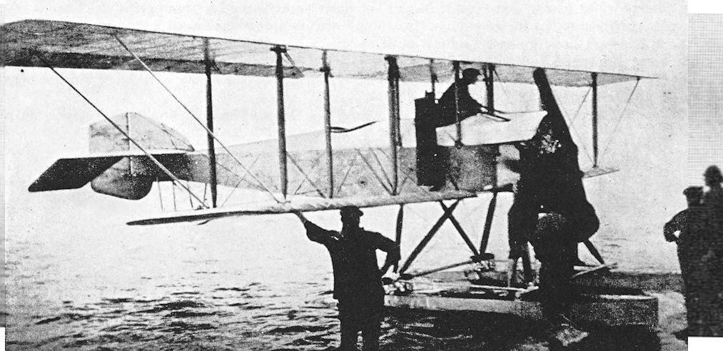
The Blackburn Type L seaplane which was to have been flown by Sydney Pickles in the 1914 Circuit of Britain.
Blackburn T.B.
THIS remarkable aeroplane was the Blackburn company’s first attempt to produce an aircraft designed for warlike purposes; it made its appearance in August, 1915. The T.B. was designed to fulfil Admiralty requirements for an anti-Zeppelin aircraft, and the specified armament was to consist of a load of steel darts. No doubt these missiles were Ranken Darts, an ingenious weapon which was designed to catch in the envelope of an airship and explode inside. The darts were usually carried in canisters of 24.
Any justification for the adoption of the complicated twin-fuselage layout for the aircraft is hard to find: it may have been hoped to produce an aeroplane capable of lifting a heavy load of fuel to obtain a long flight endurance, in which case it might have been thought necessary to provide two pilots to minimise crew fatigue. However, the relatively low power of the engines which were fitted did not permit the lifting of heavy loads.
Two prototypes were built. The first had two 100 h.p. Gnome Monosoupape rotary engines, and the second had two 110 h.p. Clergets. Blackburns were Admiralty contractors for the B.E.2C at the time of the construction of the T.B., and the two fins of the big twin were standard B.E.2C components, whilst the rudders were also of B.E. design but were slightly modified in outline.
The structure was conventional throughout. The fuselages were wooden box-girders, cross-braced with wire and covered with fabric. Each fuselage had a main float at its forward end and a small tailfloat under its tail; the main floats were of the pontoon type and were not connected to one another. The long extensions of the upper wings were braced from above and below by cables. Ailerons were fitted to both upper and lower mainplanes: those on the upper wing were long and inversely tapered; the lower ailerons were very short.
The performance of the Blackburn T.B. was quite creditable in view of its layout, but it could hardly have fared well in service. Difficulty of communication between the occupants of the two fuselages would have been a formidable handicap in action.
The T.B. was tested at the R.N.A.S. Station, Isle of Grain, and the second machine, No. 1517, was there in 1916.
SPECIFICATION
Manufacturers: The Blackburn Aeroplane & Motor Co., Ltd., Olympia, Leeds.
Power: First machine: two 100 h.p. Gnome Monosoupape. Second machine: two 110 h.p. Clerget.
Dimensions: Span: upper 60 ft 6 in., lower 45 ft. Length: 36 ft 6 in. Chord: 5 ft 6 in. Gap: 6 ft 6 in. Stagger: nil. Dihedral: 40. Incidence: 40.
Areas: Wings: upper 341 sq ft, lower 244 sq ft, total 585 sq ft. Ailerons: total 35-25 sq ft. Tailplane: 37 sq tt. Elevators: 27-25 sq ft. Fins: 15-25 sq ft. Rudders: 36 sq ft.
Weights: Empty: 2,310 lb. Military load: 70 lb. Crew: 360 lb. Fuel and oil: 760 lb. Weight loaded: 3,500 lb.
Performance (with Gnome engines): Maximum speed at sea level: 86 m.p.h. Climb to 5,000 ft: 12 min. Endurance: 4 hours.
Armament: 70 lb of steel darts.
Serial Numbers: 1510 and 1517.

Rear view of the Clerget-engined T.B. seaplane.
Blackburn White Falcon
THIS somewhat grandiosely-named monoplane had every appearance of being a development of the Land/Sea Monoplane of 1915, and was probably built in 1916. It was a neat aeroplane of simple outline, powered by an Anzani radial engine of 100 h.p. which drove a four-bladed airscrew.
The fuselage was of rectangular cross-section with a rounded decking, whereas all previous Blackburn monoplanes, including the Land/Sea trainer, had had fuselages of triangular section. The wings were attached to the upper longerons, and lateral control was by means of wing-warping. The undercarriage legs were of an unusual form: they were a compromise between the old type with horizontal skids and the later vee type. No doubt this was to some extent dictated by the necessity to provide points of anchorage for the flying wires and points of attachment for the pulleys over which the warping cables ran. The tailskid was probably a standard B.E.2c component.
The White Falcon’s designed purpose and history are alike obscure. It has been described as a military monoplane, but it is hard to see what military function it could discharge. It was normally flown from the rear seat, and the observer in the front seat could observe little; nor could he use a gun satisfactorily, surrounded by bracing and warp-balance cables running up to the cabane struts. It may have been designed as a trainer.
The machine bore the monogram of W. Rowland Ding on the rudder, and was probably used by him either for pleasure or as a means of personal transport.
SPECIFICATION
Manufacturers: The Blackburn Aeroplane & Motor Co., Ltd., Olympia, Leeds.
Power: 100 h.p. Anzani.
Dimensions: Span: 39 ft 6 in. Length: 26 ft 11 1/4 in. Chord: 7 ft. Dihedral: 2. Incidence: 4. Airscrew diameter: 9 ft.
Areas: Wings: 209 sq ft.
Tankage: Petrol: 30 gallons.
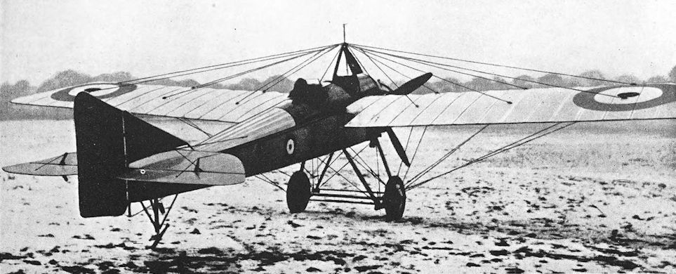
The White Falcon in military marks during the winter of 1916-17.
Blackburn G.P. and S.P.
THE Blackburn G.P. appeared in 1916. It was a large twin-engined biplane with a twin-float undercarriage, and was designed as a three-seat patrol bomber. It was one of the earliest aircraft designed to carry a torpedo. The upper wings had long wire-braced extensions, and bore the ailerons; there were no control surfaces on the lower wings. The G.P. was powered by two 225 h.p. Sunbeam engines which drove opposite-handed four-bladed airscrews. The radiators were mounted vertically on each rear interplane strut flanking the engine nacelles.
The wings could be folded to facilitate stowage. This structural feature was not unique in 1916, but was still regarded as unusual, particularly in such a large machine.
The second aircraft to be built to the same basic design as the G.P. embodied a greater proportion of metal components, and was powered by two 250 h.p. Rolls-Royce Falcon engines. This version was designated Blackburn S.P., and externally had little to distinguish it from the G.P. The engines again drove four-bladed airscrews, but the exhaust pipes ran along the sides of the nacelles instead of above, as in the case of the Sunbeam engines which had their exhaust valves on the inboard sides of the cylinders.
The principal difference between the S.P. and the G.P. lay in the greatly increased aileron area of the S.P. Ailerons were fitted to the lower mainplanes: they extended from the second pair of interplane struts out to the wing-tips, and the ailerons on the upper wing were lengthened correspondingly. Upper and lower ailerons were connected by a faired steel tube, and it seems probable that they may have been arranged to droop together and thus act as air-brakes, in the manner of the later Kangaroo. The trailing edges of the S.P.’s rudders were made of wire; consequently they were “feathered”, whereas the more substantial trailing edges of the rudders of the G.P. were quite straight.
The type did not go into production, but a landplane conversion named the Kangaroo was built in some numbers. The tests of the G.P. were carried out at the Isle of Grain, and the S.P. was tested at Brough.
SPECIFICATION
Manufacturers: The Blackburn Aeroplane & Motor Co., Ltd., Olympia, Leeds.
Power: G.P.: two 225 h.p. Sunbeam. S.P.: two 250 h.p. Rolls-Royce Falcon.
Dimensions: Span: upper 74 ft 10 1/4 in., lower 52 ft 10 1/2 in. Length: 46 ft. Height: 16 ft 10 in. Chord: 7 ft 3 in. Gap: 7 ft 3 in. Stagger: nil. Dihedral: 5. Incidence: 5. Span of tail: 17 ft 6 in.
Areas: Wings: upper 536 sq ft, lower 344 sq ft, total 880 sq ft. Ailerons: total 166-5 sq ft (on S.P.). Tailplanes: 80 sq ft. Elevators: 63-5 sq ft. Fins: 25 sq ft. Rudders: 22-5 sq ft.
Weights: (S.P.) Empty: 5,840 lb. Military load: 1,170 lb. Crew: 540 lb. Fuel and oil: 1,050 lb. Weight loaded: 8,600 lb.
Performance: (S.P.) Maximum speed at sea level: 97 m.p.h.; at 10,000 ft: 77 m.p.h. Climb to 5,000 ft: 10 min; to 10,000 ft: 30 min. Ceiling: 11,000 ft. Endurance: 8 hours.
Tankage: Petrol: 230 gallons. Oil: 18 gallons.
Armament: Two free Lewis machine-guns on Scarff ring-mountings, one on the nose cockpit, the other on the rear cockpit aft of the wings. Four 230-lb bombs or one torpedo.
Serial Numbers: 1415 (G.P.) and 1416 (S.P.).

The first Blackburn GP seaplane, No 1415 powered by Sunbeam engines, at RNAS Isle of Grain in 1916. Note the use of a tailfloat, made necessary by the relatively short mam floats. It is not thought likely that a GP ever carried a torpedo into the air.
Only two examples of the three-seat Blackburn GP long range patrol and torpedo bomber were built, the first being completed in July 1916. These two contemporaries and rivals to the Short Type 310 differed in both structural detail and the type of engine employed. The first example, serial no 1415 seen here, used twin 150hp Sunbeam Nubians, while serial no 1416, which did not emerge until near the close of 1916, was powered by twin 190hp Rolls-Royce Falcons. The top level speed of the latter floatplane was 97mph at sea level, its ceiling 11.000 feet and climb to 5,000 feet took 10 minutes. Armament comprised two flexibly-mounted .303-inch Lewis guns, plus a 14-inch torpedo, or four 230lb bombs. The Admiralty elected not to proceed with further development, but a landplane version, powered by twin 270hp Rolls-Royce Falcon IIIs and known as the Blackburn Kangaroo was subsequently produced for the RFC, who took 20 examples.
Only two examples of the three-seat Blackburn GP long range patrol and torpedo bomber were built, the first being completed in July 1916. These two contemporaries and rivals to the Short Type 310 differed in both structural detail and the type of engine employed. The first example, serial no 1415 seen here, used twin 150hp Sunbeam Nubians, while serial no 1416, which did not emerge until near the close of 1916, was powered by twin 190hp Rolls-Royce Falcons. The top level speed of the latter floatplane was 97mph at sea level, its ceiling 11.000 feet and climb to 5,000 feet took 10 minutes. Armament comprised two flexibly-mounted .303-inch Lewis guns, plus a 14-inch torpedo, or four 230lb bombs. The Admiralty elected not to proceed with further development, but a landplane version, powered by twin 270hp Rolls-Royce Falcon IIIs and known as the Blackburn Kangaroo was subsequently produced for the RFC, who took 20 examples.

The second G.P. seaplane 1416 ready for launching and showing the scalloped trailing edges to all flying surfaces.
This illustration shows the feathered trailing edges of the rudders, and the enlarged upper ailerons.
This illustration shows the feathered trailing edges of the rudders, and the enlarged upper ailerons.
Blackburn Triplane
WORK on the design of the Blackburn Triplane began at the end of 1915. It was a single-seat fighter which was intended to achieve the same object as the contemporary D.H.a; namely, to provide a fighting aircraft with armament which could be fired straight ahead.
The Blackburn Triplane obviously owed a good deal to the A.D. Sparrow, for which the Blackburn company had been contractors, and it is probable that Harris Booth had a hand in the design of the triplane. There was the same enormous gap between upper and lower tail-booms; a long-span tailplane was fitted; there were two large, widely-spaced fins and rudders; and in appearance the nacelle was as uncouth as that of the Sparrow. On the triplane, ailerons were fitted to all wings; only the central ailerons were connected directly to the pilot’s control column, and the top and bottom surfaces were actuated by connecting struts. The tail-booms were parallel in both plan and side elevation, and the entire tail assembly appeared to be of doubtful rigidity. The machine was flown with both the 100 h.p. Gnome Monosoupape and the 110 h.p. Clerget engines: in the latter case a four-bladed airscrew was used.
The only available performance figures credit the Triplane with a maximum speed of 115 m.p.h. with the Monosoupape engine, but this claim must be regarded as somewhat optimistic; for the D.H.2 could reach only 93 m.p.h. with the same engine.
It has been said that two Blackburn Triplanes were built, one of which was tested at York and the second sent to Eastchurch. However, it seems unlikely that two machines existed; it is more probable that a confusion with the A.D. Sparrow arose.
SPECIFICATION
Manufacturers: The Blackburn Aeroplane & Motor Co., Ltd., Olympia, Leeds.
Power: 100 h.p. Gnome Monosoupape; 110 h.p. Clerget.
Dimensions: Span: 24 ft. Length: 21 ft 5 5/16 in. Chord: 3 ft 5 in. Gap: 3 ft 6 in. Stagger: 9 in. Dihedral: nil. Incidence: 2°. Span of tail: 18 ft. Wheel track: 5 ft. Airscrew diameter: 8 ft.
Areas: Wings: top 79-108 sq ft, middle 67-116 sq ft, bottom 74-806 sq ft, total 221-03 sq ft. Ailerons: each 6-53 sq ft, total 39-2 sq ft. Tailplane: 29-7 sq ft. Elevators: 25-1 sq ft. Fins: 15-2 sq ft. Rudders: 23-9 sq ft.
Weights: Empty: 1,011 lb. Military load: 50 lb. Pilot: 180 lb. Fuel and oil: 259 lb. Weight loaded: 1,500 lb.
Performance (with Monosoupape engine): Maximum speed: 115 m.p.h. Endurance: 3 hours.
Armament: One free-mounted forward-firing Lewis machine-gun in front of pilot.
Serial Number: N.502, built under Contract No. C.P. 120730/16.

The Blackburn triplane scout. 100 h.p. Gnome Monosoupape
Blackburn Kangaroo
THE Kangaroo was a landplane development of the G.P. and S.P. seaplane design, and was intended for Service use as a bomber. In general appearance it was virtually identical to the earlier floatplanes, apart from the substitution of the wheel undercarriage. The Kangaroo’s rudders were of slightly greater area, and the kingpost structures above the upper wing were rectangular; those of the floatplanes had been triangular.
The undercarriage had four wheels arranged in two pairs; each pair of wheels was mounted on two vee-struts directly under each engine. The original undercarriage was noteworthy for the complete absence of shock absorbers, but later the front leg of each vee incorporated an oleo strut.
Development of the Kangaroo seems to have proceeded rather slowly. The trials during which the appended performance figures were obtained were conducted in January, 1918. The Kangaroo which was used was B.9970, which at that time still had the rigid undercarriage.
The official report on the type was not particularly complimentary. The small cross-section of the fuselage was adversely criticised, both structurally and from the standpoint of crew comfort and function. When coming out of a steeply-banked turn, the fuselage would twist aft of the rearmost cockpit, indicating a lack of torsional rigidity; and it was too shallow to allow the gunners to make effective use of their guns. The Kangaroo was said to be quite pleasant to fly, but was markedly nose heavy with power off, and the rudders were described as “difficult to operate”; rudder pedals were fitted in place of the more common rudder bar. The ailerons on both upper and lower wings were arranged to droop to act as air brakes; and the wings could be folded.
Limited production of the Kangaroo was undertaken, but only eleven machines had been delivered by the time of the Armistice. The Kangaroo’s active service was chiefly given as the equipment of an anti-submarine squadron at Seaton Carew, near the mouth of the River Tees, but the machine is also said to have been used for a short time by a bomber squadron in Belgium in 1918. It was reported that the Kangaroo bombers suffered badly from enemy bombing of their aerodrome.
The machines of the Seaton Carew squadron flew 600 hours on anti-submarine patrols between May 1 st, 1918, and the date of the Armistice. During that time the Kangaroos sighted twelve U-boats and attacked eleven of them.
Kangaroo B.9983 from Seaton Carew was instrumental in bringing about the destruction of the enemy submarine U.C.70 on August 28th, 1918. The machine was flown by Lieutenant E. F. Waring with Lieutenant H. J. Smith as his observer, and they sighted the submarine at 3.25 p.m., apparently lying on the sea-bed near Runswick Bay. Waring dropped a 520-lb bomb, which exploded 30 feet from the bows of the submarine, and the destroyer H.M.S. Ouse came up to drop depth charges, the last of which exploded directly on top of the U-boat’s hull.
After the war the surviving Kangaroos returned to the Blackburn company at Brough, and many were converted for commercial use in one way or another. Three were acquired by the Grahame-White Aviation Company for joy-riding at Hendon, and four were operated by the North Sea Aerial Navigation Co., Ltd., an offshoot of the Blackburn concern.
In an attempt to win the Australian Government’s prize of £10,000 for the first England-Australia flight by a Commonwealth airman, the Kangaroo G-EAOW left Hounslow on November 21st, 1919, bound for Australia - nine days after the departure of Ross and Keith Smith in their Vickers Vimy. This Kangaroo was powered by two specially tuned Rolls-Royce Falcon Ills fitted with special carburettors and 12-point magnetos. The crew of the Kangaroo were Lieutenants Vai Rendle and D. R. Williams, Captain G. H. Wilkins, M.C., and Lieutenant G. H. Potts. Unfortunately the flight had to be abandoned on December 8th after a forced landing made at Canea, Crete.
The last Kangaroos were those which were used as trainers until 1929 by the renamed North Sea Aerial and General Transport Co., Ltd. The aircraft were used to provide twin-engine training at the R.A.F. Reserve School, Brough.
SPECIFICATION
Manufacturers: The Blackburn Aeroplane & Motor Co., Ltd., Olympia, Leeds. Power: Two 250 h.p. Rolls-Royce Falcon.
Dimensions: Span: upper 74 ft 10 1/4 in., lower 52 ft 10 1/2 in. Length: 46 ft. Height: 16 ft 10 in. Chord: 7 ft 3 in. Gap: 7 ft 3 in. Stagger: nil. Dihedral: 5. Incidence: 5. Span of tail: 17 ft 6 in. Track of each undercarriage unit: 5 ft. Tyres: 900 X 200 mm. Airscrew diameter: 9 ft 10 in.
Areas: Wings: upper 536 sq ft, lower 344 sq ft, total 880 sq ft. Total aileron area: 166-5 sq ft. Tailplanes: 80 sq ft. Elevators: 63-5 sq ft. Fins: 25 sq ft. Rudders: 22-5 sq ft.
Weights and Performance: No. of Trial Report: M.169. Date of Trial Report: January, 1918. Type of airscrew used on trial: S.D.440. Weight empty: 5,284 lb. Military load: 463 lb. Crew: 540 lb. Fuel and oil: 1,730 lb. Loaded: 8,017 lb. Maximum speed at ground level: 100 m.p.h.; at 6,500 ft: 98 m.p.h.; at 10,000 ft: 86 m.p.h. Climb to 1,000 ft: 2 min; to 2,000 ft: 4 min 10 sec; to 5,000 ft: 12 min 30 sec; to 6,500 ft: 18 min 10 sec; to 8,000 ft: 25 min 05 sec; to 10,000 ft: 38 min 10 sec; to 10,600 ft: 44 min. Service ceiling: 10,500 ft. Endurance: 8 hours.
Tankage: Petrol: front pressure tank 97 1/2 gallons; rear pressure tank 118 gallons; total 215 1/2 gallons. Oil: two tanks, one on inside of each engine, 16 gallons. Water: 7 1/4 gallons.
Armament: One Lewis machine-gun on Scarff ring-mounting on nose cockpit; another Lewis gun was similarly installed on the rear cockpit. The original conception of the machine envisaged an underslung position for a prone lower rear gunner, accommodated in a “bath” structure below the rear cockpit; this idea was abandoned. Four 230-lb bombs could be carried internally, suspended by their noses, and there were external racks for four bombs under the fuselage.
Service Use: Used by an anti-submarine squadron (probably No. 246) at Seaton Carew. A few may have been used with a bomber unit based in Belgium.
Production and Allocation: Eleven Kangaroos were delivered to the R.A.F. in 1918, but at least fifteen had been built by October 31st, 1918. On that date, ten were with the Seaton Carew squadron, one was at a training unit, and three were at Aircraft Acceptance Parks; one machine was written off during October.
Serial Numbers: B.8837-B.8840; B.9970-B.9989 (originally ordered as N.1720-N.1739) built under Contract No. A.S.7469.
Costs:
Airframe without engines, instruments or armament £5,648
Rolls-Royce Falcon engine (each) £1,210
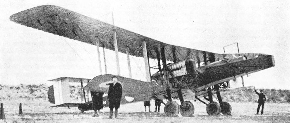
Blackburn Kangaroo with the original unsprung undercarriage.
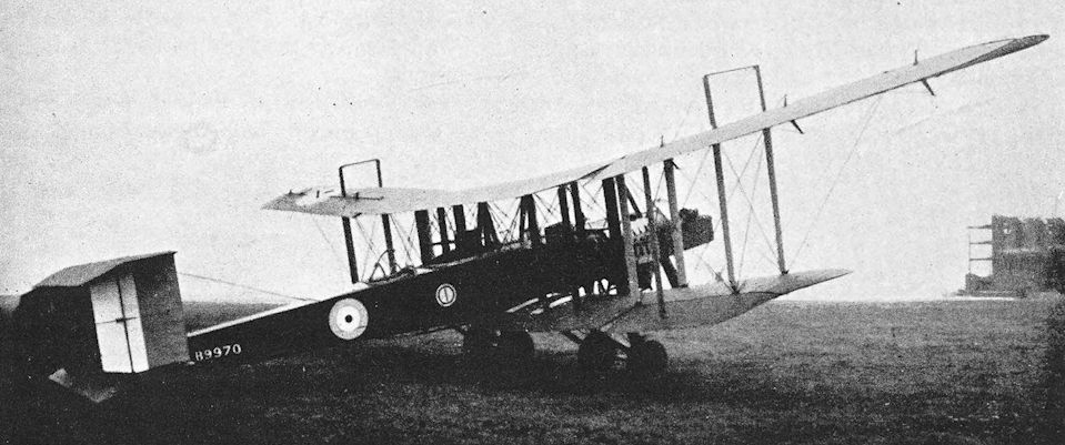
Blackburn Kangaroo.
Blackburn Blackburd
BY the end of 1917, the idea of using torpedo-carrying landplanes operating from aircraft-carriers had been accepted, and the Sopwith Cuckoo was in production. The Cuckoo’s warload consisted of a Mark IX eighteen-inch torpedo which contained 170 lb of T.N.T., but official opinion at the end of 1917 was that the Mk. IX torpedo was not sufficiently powerful to be effective against battleships.
It was therefore requested that an aeroplane be provided which would be capable of carrying the Mk. VIII torpedo, containing 320 lb of T.N.T. A specification was issued and orders for three prototypes each were given to the Blackburn company and to Short Brothers. The resulting aircraft were the Blackburd and the Shirl respectively.
The Blackburd was not the first Blackburn type to carry a torpedo, for both the G.P. and the Kangaroo had been capable of doing so; but it was the first Blackburn aeroplane to be specifically designed for that purpose.
The Blackburd was obviously designed for ease and rapidity of production, and its box-like fuselage of constant depth was evidence enough that the smallest pretence of elegance had been ruthlessly suppressed in the attainment of utility. Since the machine was intended for shipboard use the design incorporated folding wings, the aeroplane’s most remarkable feature lay in its undercarriage, however.
At the time the Blackburd appeared, deck landing was still in its infancy. Much experimental work had been carried out at the Marine Experimental Aircraft Depot, Isle of Grain, with Sopwith Pups and 1 1/2-Strutters, fitted with wheel-less skid undercarriages. It was recognised that some form of arrester gear was necessary, but none had been standardised by the time of the Armistice.
The Blackburd’s undercarriage sought to have the best of two worlds by providing wheels for take-off and steel skids for landing. In view of the machine’s designed function, it is remarkable that the two wheels were connected by a rigid transverse axle. The wheels and axle had to be jettisoned before the torpedo could be dropped, and the landing was made on the skid portion of the undercarriage which remained. Shock absorption was provided by two oleo struts, one on each side.
A further argument advanced in support of the arrangement was that the absence of wheels would minimise the danger of nosing over if the Blackburd were forced to alight on the water. Inflatable air bags were fitted inside the fuselage to serve as emergency flotation gear.
The test flights and first skid landings were carried out by R. W. Kenworthy. The skids underwent various modifications before they were pronounced satisfactory. By that time the war was over and the need for the Blackburd had passed. On test, the machine proved to be somewhat inferior to the Sopwith Cuckoo, for it was slower and lacked the manoeuvrability required during close-range attacks.
The second Blackburd, N.114, differed from the first in having small floats attached to the underside of the lower wings in similar fashion to the Beardmore W.B.IV. It also had a larger, squarer radiator and a deeper nose.
SPECIFICATION
Manufacturers: The Blackburn Aeroplane & Motor Co., Ltd., Olympia, Leeds.
Power: 350 h.p. Rolls-Royce Eagle VIII.
Dimensions: Span: upper 52 ft, lower 52 ft 6 in. Length: 36 ft 3 in. Height: 12 ft 4 1/2 in. Chord: 7 ft. Gap: 7 ft. Stagger: -1°. Dihedral: 2° 03'. Incidence: 0° 45'. Span of tail: 17 ft.
Weights (lb) and Performance:
Without Torpedo With Torpedo
No. of Trial Report M.208 M.208
Date of Trial Report June, 1918 June, 1918
Type of airscrew used on trial A.B.8520 A.B.8580
Weight empty 3,228 3,228
Military load - 1,671
Pilot 180 180
Fuel and oil 512 621
Weight loaded 3,920 5,700
Maximum speed (m.p.h.) at
ground level - 92
6,500 ft 95 90-5
10,000 ft 94-5 84-5
15,000 ft 89-5
m. s. m. s.
Climb to
6,500 ft 8 40 16 10
10,000 ft 15 05 33 25
15,000 ft 28 40 - -
Service ceiling (feet) 19,000 11,000
Endurance (hours) - 3
Areas: Wings: upper 345-5 sq ft, lower 349-5 sq ft, total 695 sq ft. Total aileron area: 77-5 sq ft. Tailplane: 61 sq ft. Elevators: 27 sq ft. Fin: 19-5 sq ft. Rudder: 9 sq ft.
Tankage: Petrol: 69 gallons. Oil: 9 gallons.
Armament: One Mark VIII torpedo of 1,400 lb in crutches below the fuselage.
Serial Numbers: N. 113-N. 115.

Blackburn Blackburd. The first Blackburd, N.113.

Blackburn Blackburd. The second machine, N.114, with wing-tip floats and rectangular radiator.

The undercarriage of Blackburd N115 showing the steel landing skids, wheel-jettison control cable running parallel to the rear strut, and the experimental hydrovanes.
An experimental undercarriage on the Blackburd. Multiple hydrofoils were carried on the forward struts, which were of increased chord, and on the skids, in order to improve ditching characteristics. The torpedo can also be seen.
An experimental undercarriage on the Blackburd. Multiple hydrofoils were carried on the forward struts, which were of increased chord, and on the skids, in order to improve ditching characteristics. The torpedo can also be seen.
Blackburn N.1B
CONSTRUCTION of the Blackburn N.1B began in 1917. It was designed as a single-seat fighter flying boat, and was intended to be used as an escort to the big patrol flying boats. Not unnaturally, the machine was known as the “Nib” in the Blackburn works: its true designation N.1B derived from the number of the Admiralty category to which it was appropriate.
The hull was of Linton Hope design, and its structure was the typical framework of circular wooden hoops and stringers, planked diagonally with strips of mahogany. There were two steps, and the top line of the hull swept upwards slightly to the biplane tail unit. As on the A.D. Flying Boats, the upper tailplane had reversed camber. Both mainplanes and tailplanes were designed to have elliptical tips, and the mainplanes were arranged to fold. The 200 h.p. Hispano-Suiza engine was installed as a pusher under the upper centre-section.
Unfortunately, Service requirements changed while the N.1B was building, and only the hull was completed by the time of the Armistice. This hull was still in excellent condition in 1923, when the Blackburn company decided to enter a machine in the Schneider Trophy contest. It was therefore fitted with biplane wings of sesquiplane configuration and a single-rudder monoplane tail unit. A 450 h.p. Napier Lion engine was installed above the upper wing, and drove a tractor airscrew which revolved in perilous proximity to the pilot’s head.
In this form the machine was named the Blackburn Pellet and was registered G-EBHF. It was to be flown by R. W. Kenworthy in the Schneider Trophy contest at Cowes. When first launched for trials in the Humber the Pellet went down on her starboard wing, turned over slowly, and threw Kenworthy into the river. Salvage, repair and modifications to the wing-tip floats left time for only one test flight on the eve of the race, and during that flight Kenworthy found that the Pellet was nose-heavy. There was no time to correct this fault, but larger Lamblin radiators were installed by all-night work on the part of the Blackburn mechanics: the original radiator was inadequate, and Kenworthy had been forced to alight hurriedly with the water boiling.
The Pellet’s next and last flight was begun as part of the navigability trials which were included in the contest. The machine became airborne at 140 knots, but immediately porpoised badly, turned turtle and sank. Miraculously, Kenworthy survived unhurt.
SPECIFICATION
Manufacturers: The Blackburn Aeroplane & Motor Co., Ltd., Olympia, Leeds.
Power: 200 h.p. Hispano-Suiza.
Dimensions: Span: upper 34 ft 10 in., lower 29 ft 4 in. Length: 28 ft 3 1/2 in. Chord: 5 ft 6 in. Gap: 6 ft 9 in. Stagger: 3. Dihedral: 3. Incidence: 3.
Areas: Wings: upper 170 sq ft, lower 144 sq ft, total 314 sq ft. Ailerons: each 41-5 sq ft, total 83 sq ft. Tailplanes: 30-25 sq ft. Elevators: 21-5 sq ft. Fins: 11 sq ft. Rudders: 9 sq ft.
Weights: Empty: 1,721 lb. Loaded: 2,390 lb.
Performance (Estimated): Maximum speed at sea level: 114 m.p.h.; at 10,000 ft: 108 m.p.h. Climb to 5,000 ft: 7 min; to 10,000 ft: 18 min. Ceiling: 16,000 ft. Endurance: 3 hours.
Armament: One forward-firing Lewis machine-gun mounted above the hull in front of the cockpit, to starboard of centre.
Serial Numbers: N.56-N.58.

Blackburn N.1B. A photograph of a model of the N.1B. It was never completed in this form.
Boulton & Paul P.3, the Bobolink
IN common with many other firms which normally engaged in wood-working of one kind or another, Messrs Boulton & Paul, Ltd., of Norwich, undertook the construction of aircraft during the 1914-18 war. From the manufacture of wooden buildings the firm turned to the production of such aeroplanes as the F.E.ad, Sopwith 1 1/2-Strutter and Sopwith Camel. Under the energetic management of Geoffrey Ffiske the firm developed its aircraft side with J. D. North as chief designer. It is not surprising therefore that a Boulton & Paul design appeared in 1918.
This first Boulton & Paul aeroplane was a single-seat fighter biplane, designated P.3 and at first named “Hawk” by its manufacturers. It was later officially named Bobolink, however. It was the company’s entry in the design competition for a single-seat fighter with the 230 h.p. Bentley B.R.2 engine to replace the Sopwith Camel. The competition was ultimately won by the Sopwith Snipe, however, and the Bobolink did not go into production. The Bobolink’s all-round performance was rather better than that of the Snipe, and its flying characteristics were good. Unfortunately, the comparatively narrow track of the undercarriage made the Bobolink somewhat difficult to handle on the ground, and this fact was to some extent responsible for the machine’s lack of success.
A less understandable official reason for the non-acceptance of the Bobolink was that the Snipe was considered to be a slightly simpler aircraft and more suitable for production in quantities. How this view could be justified is not immediately clear, particularly if the Snipe’s rounded fuselage with its complications of formers and stringers is compared with the plain wire-braced box girder structure of the Bobolink. An unusual structural feature of the Bobolink was the use of N-type interplane struts, but that should have simplified rigging and could not, in fairness, be regarded as a drawback. The wings were remarkably light: each lower mainplane weighed only 29 lb before covering.
In general, detail design closely followed Sopwith practice, and all fittings required a minimum of machining.
The fuel supply was carried in two main tanks located immediately behind the pilot’s seat and separated by a sheet of armour plate: this, it was hoped, would minimise the risk of any one bullet damaging both tanks. The main fuel tanks could be jettisoned in flight, in order to avoid complete destruction of the aeroplane in the event of the petrol being set on fire.
SPECIFICATION
Manufacturers: Boulton & Paul, Ltd., Riverside, Norwich.
Power: 230 h.p. Bentley B.R.2, engine No. E.X.4.
Dimensions: Span: 29 ft. Length: 20 ft. Height: 8 ft 4 in. Chord: upper 5 ft 4 1/2 in., lower 4 ft in. Gap: 3 ft 10 5/8 in. Stagger: 2 ft 3 1/2 in. Dihedral: 2° 30'. Incidence: 0°. Span of tail: 9 ft 2 in. Airscrew diameter: 9 ft.
Areas: Wings: 266 sq ft. Ailerons: each 7.5 sq ft, total 15 sq ft. Tailplane: 20 sq ft. Elevators: 10 sq ft. Fin: 2 sq ft. Rudder: 10 sq ft.
Weights and Performance: No. of Trial Report: M.188. Date of Trial Report: March, 1918. Type of airscrew used on trial: Lang 4040.
Weights: Empty: 1,226 lb. Military load: 228 lb. Pilot: 180 lb. Fuel and oil: 358 lb. Weight loaded:, 1,992 lb.
Performance: Maximum speed at 10,000 ft: 125 m.p.h.; at 15,000 ft: 109 m.p.h. Climb to 6,500 ft: 5 min 20 sec; to 10,000 ft: 9 min 20 sec; to 15,000 ft: 18 min. Service ceiling: 19,500 ft. Endurance: 3 1/4 hours at 15,000 ft.
Tankage: Petrol: main tank 34 gallons, auxiliary tank 6 gallons; total 40 gallons.
Armament: Two Vickers machine-guns mounted on top of the fuselage and synchronised to fire forward through the revolving airscrew. The original design included a semi-free Lewis gun above the centre-section.
Serial Numbers: C.8652-C.8657: ordered under Contract No. A.S.37485.
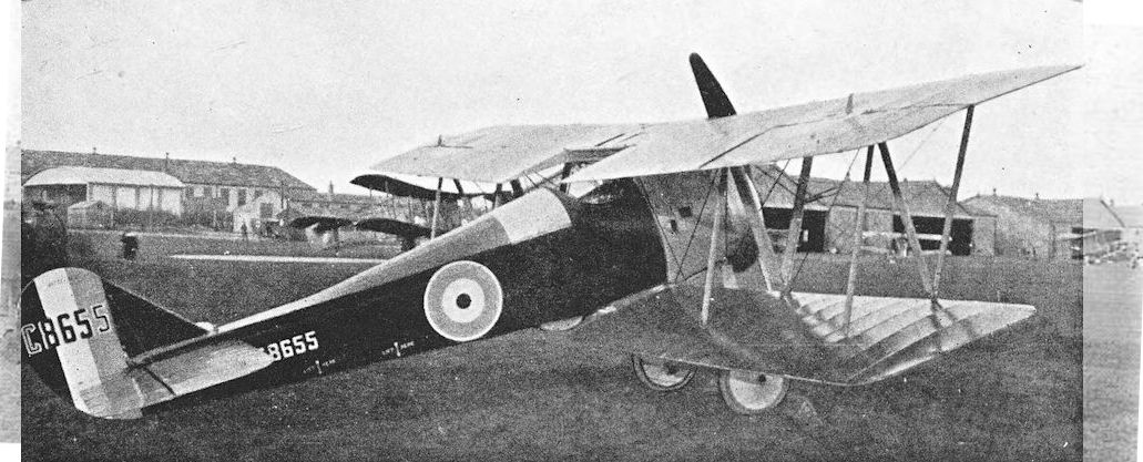
The Bobolink at Mousehold on 19 February, 1918, with different propeller, no Lewis gun, but still with ailerons on upper wing only.
Boulton & Paul P.7, the Bourges
THE manoeuvrability of the Boulton & Paul Bourges, especially when demonstrated by Captain F. T. Courtney, is now almost legendary; and indeed its tractability was remarkable for its day, when all twin-engined aeroplanes were regarded as elephantine and unlikely to commit any indiscretion such as a loop.
The Bourges was a sturdy, well-proportioned biplane intended for service as a fighter-bomber. Design work began in 1918 and three prototypes were ordered. The official designations of the several versions of the Bourges differ from those which have gained a certain currency; the official Mark numbers are as quoted below.
The Bourges was designed originally to have two 320 h.p. A.B.C. Dragonfly engines. This version was officially named Bourges Mark I, and the suffix letter A was to be added to indicate a conventional straight-through upper centre-section, whilst suffix B was to indicate a dropped or gull-wing centresection.
However, the first Bourges airframe, F.2903, was ready before engines were available. It was desired to carry out test flights as quickly as possible, so the machine was fitted with two 230 h.p. Bentley B.R.2 rotary engines in order to enable it to be flown. Plain ailerons were fitted. This version was officially designated Bourges Mk. II - or, more fully, Mk. IIA, for it had a straight-through centre-section. This designation is exactly analogous to the designations of the B.A.T. Bantam II, Avro Manchester Mk. II and Sopwith Cobham Mk. II.
When Dragonfly engines became available they were installed in F.2903. At first they had very clean nacelles with large blunt spinners on the airscrews, but these did not prove satisfactory, aerodynamically or structurally. The spinners were removed and modified engine cowlings were fitted. In this form the Bourges had horn-balanced ailerons, and ultimately the rudder area was slightly increased. The official designation of this version was Bourges Mk. IA.
It is in this form that the Bourges is best remembered. For a twin-engined aeroplane its manoeuvrability was phenomenal, thanks to its relatively short wing span and low wing loading: it could be looped, rolled and spun almost as easily as contemporary fighters.
The second Bourges, F.2904, was officially designated Mark IB (though it has been popularly better known as the Mk. IA), and differed considerably from the true Mk. IA. With the object of improving the rear gunner’s field of fire, the upper mainplane was made as a gull wing: from the struts above the engines the wing sloped downwards to meet the top of the fuselage. Equally unusual was the sharp dihedral angle on the tailplane; each half was parallel to the inclined portions of the upper mainplane. The Dragonfly engines were mounted directly on to the lower mainplane and the enlarged rudder was fitted. The fin area was reduced slightly, and the vertical tail surfaces were therefore more nearly circular in outline.
Under the designation Bourges Mk. Ill a further version was projected with two Siddeley Puma engines, most probably of the ago h.p. high-compression type which was used as an alternative to the A.B.C. Dragonfly in the contemporary Avro Manchester and Sopwith Cobham. This version was never built, but the third Bourges airframe, F.2905, was completed and flown with two Napier Lion engines of 450 h.p. each. The engines were mounted on the lower wings, and additional sloping struts were added to the centre-section bracing. The Lion-powered Bourges had the same fin and rudder as the Mk. IB. It has usually been known as the Bourges Mk. II, but that official designation had already been used for the version with B.R.2 engines.
SPECIFICATION
Manufacturers: Boulton & Paul, Ltd., Riverside, Norwich.
Power: Bourges Mk. I: two 320 h.p. A.B.C. Dragonfly I. Bourges Mk. II: two 230 h.p. Bentley B.R.2. Bourges Mk. Ill: projected installation of two 290 h.p. Siddeley Puma. The third airframe was fitted with two 450 h.p. Napier Lion.
Dimensions: Span: 54 ft with plain ailerons, 57 ft 4 in. with horn-balanced ailerons. Length: 37 ft. Height: 12 ft. Chord: upper 8 ft, lower 6 ft 6 in. Gap: 6 ft 6 in. Span of tail: 16 ft. Airscrew diameter (Dragonfly): 9 ft 6in.
Areas: Wings: 738 sq ft. Ailerons: each 27 sq ft, total 108 sq ft. Tailplane and elevators: 96 sq ft. Fin: 14 sq ft. Rudder: 21 sq ft.
Weights and Performance (Dragonfly Engines) : No. of Trial Report: M.262. Date of Trial Report: August, 1919. Type of airscrew used on trial: A.B.8973. Weight empty: 3,820 lb. Military load: 436 lb. Crew: 540 lb. Fuel and oil: 1,530 lb. Loaded:6,326 lb. Maximum speed at 6,500 ft: 123-5 m.p.h.; at 10,000 ft: 121 m.p.h.; at 15,000 ft: 112-5 m.p.h. Climb to 6,500 ft: 7 min 40 sec; to 10,000 ft: 13 min 35 sec; to 15,000 ft: 25 min 25 sec. Service ceiling: 20,000 ft. Endurance: 9 1/4 hours. With Napier Lion Engines: Weight loaded: 6,800 lb. Maximum speed at 10,000 ft: 130 m.p.h.
Tankage: Petrol: 1 go gallons.
Armament: One Lewis machine-gun on Scarff ring-mounting on nose cockpit; one Lewis gun on Scarff ring-mounting on cockpit aft of wings. Bomb load.
Production: Three prototypes were built.
Serial Numbers: F.2903-F.2905.
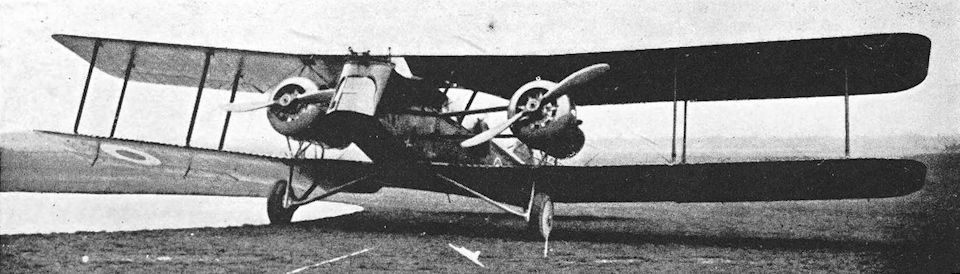
Boulton & Paul Bourges Mk. IIA. The form in which F.2903 first appeared, with B.R.2 engines and plain ailerons.
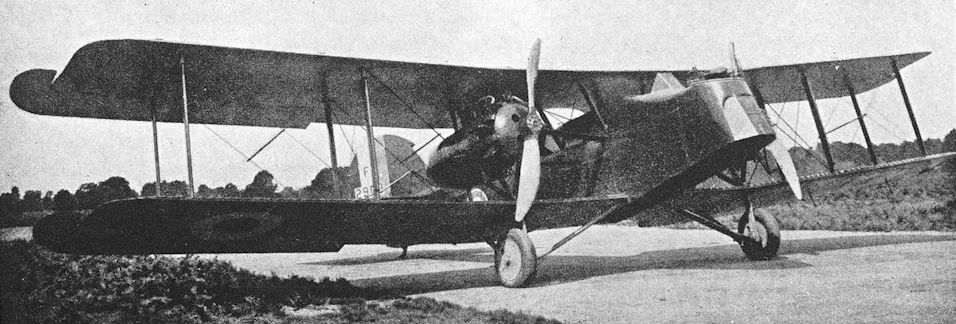
Boulton & Paul Bourges Mk. IA, with spinners removed and modified engine cowlings.
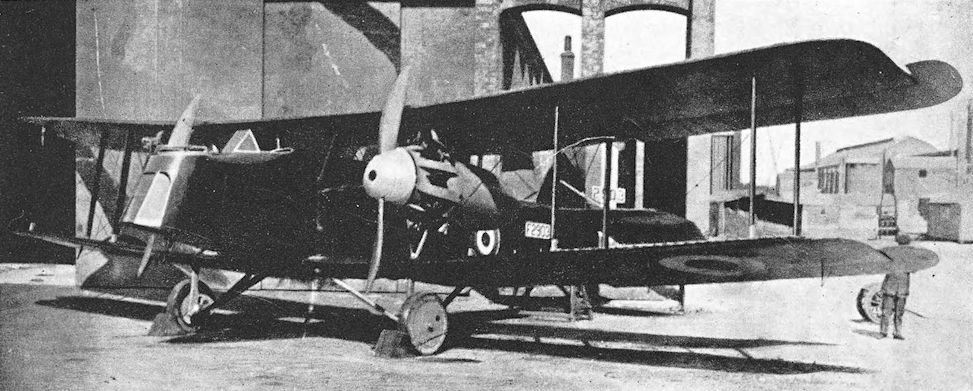
Boulton & Paul Bourges Mk. IA. The original installation of A.B.C. Dragonfly engines in F.2903, with large spinners. Horn-balanced ailerons were fitted.
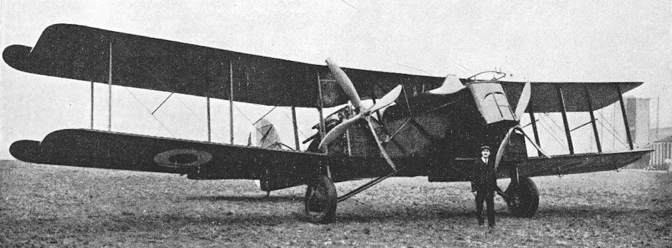
Boulton & Paul Bourges F.2905 fitted with two Napier Lion engines.
Boulton & Paul P.6
THE chubby little Boulton & Paul P.6 appeared in 1918, and is of considerable historical importance, for it was one of the earliest examples of an aeroplane built specifically for full-scale aerodynamic research, particularly for investigation of the characteristics of aerofoil sections.
The fuselage of the P.6 embodied a large number of Sopwith Camel components, and the single-bay wings were of R.A.F. 15 section in their basic form. The engine was a 90 h.p. R.A.F. Ia, which gave the little biplane quite a respectable performance. Structurally the aircraft was very simple: it was typical of its period in both methods and materials.
A considerable amount of research flying was carried out on the P.6, and the results provided useful data for the design of the later and larger P.9, which sold in some numbers in 1919 and 1920.
Early in 1919 the P.6 was put to practical use as a transport aircraft for Boulton & Paul’s general sales manager, who used it on business trips to neighbouring towns. The opportunity was taken to use the aircraft as a means of advertising, and the fuselage was boldly painted as shown in the illustration.
SPECIFICATION
Manufacturers : Boulton & Paul, Ltd., Riverside, Norwich.
Power: 90 h.p. R.A.F. Ia.
Dimensions: Span: 25 ft. Length: 19 ft. Height: 8 ft. Chord: 5 ft. Gap: 5 ft. Span of tail: 11 ft. Airscrew diameter: 9 ft 3 in. .
Areas: Wings: 235 sq ft. Ailerons: each 7-5 sq ft, total 30 sq ft. Tailplane and elevators: 40 sq ft. Fin: 2-5 sq ft. Rudder: 9 sq ft.
Weights: Empty: 1,100 lb. Disposable load: 400 lb. Fuel and oil: 225 lb. Weight loaded: 1,725 lb.
Performance: Maximum speed at 1,000 ft: 103 m.p.h. Climb to 5,000 ft: 9 min. Endurance: 2 hours 20 min.
Tankage: Petrol: 20-1 gallons.
Serial Number: X.25.
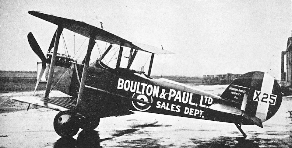
Boulton & Paul P.6.
Bristol Box-kite
THE greater part of the Bristol Box-kite’s history falls within the period before the outbreak of the 1914-18 war, yet the last contract for the type was placed by the Admiralty as late as September 26th, 1914, and one was still flying at the Australian Flying Corps School at Point Cook in October, 1915. The machine served during the war period, and therefore deserves a place in this history; but an equally strong claim for the inclusion of the Box-kite could be based on the fact that, of the four serviceable aeroplanes possessed by the R.F.C. on its formation in May, 1912, two were Bristol Box-kites.
The first true Bristol Box-kite appeared in June, 1910, and bore the British & Colonial Aeroplane Company’s works number 7. It was designed by G. H. Challenger after the company’s licence-built Zodiac biplane proved to be a failure. This machine began life with a 50 h.p. Gregoire engine, but was later converted to take the 50 h.p. Gnome rotary for use at the Bristol company’s flying school at Brooklands. The type owed a good deal to contemporary Farman designs. It was a typical primitive biplane with forward elevator and exposed pilot. Some later machines had a rudimentary nacelle, but all were characterized by the inevitable maze of bracing wires.
Two Bristol Box-kites participated in the Army manoeuvres of September, 1910, with great success. They were flown by Robert Loraine and Captain Bertram Dickson. Loraine’s machine had a 50 h.p. E.N.V. engine, and had a primitive wireless transmitting set on board, from which messages were transmitted while the Box-kite was airborne. These messages were received at a range of up to one mile. Captain Dickson’s Box-kite, which was Bristol No. 9, was specially modified for weight-carrying. Detachable extensions were fitted to the upper mainplanes, and the fuel tanks were larger than those of earlier models.
Considerable numbers of Box-kites were made, normally with the 50 h.p. Gnome, but other types of engine were fitted. From the modified Box-kite built for Captain Dickson was developed the Military type, strengthened and with a third central rudder in the tail unit. The Military type was the subject of the first contract placed by any government for a quantity of aeroplanes: eight machines, powered by the 70 h.p. Gnome, were supplied to the Russian Government in February, 1911. Two months later the first Military Box-kite for the British Army Air Battalion was delivered, followed later by five further complete machines and two spare “fuselage” structures. Two of these Box-kites had 60 h.p. Renault engines.
The first Box-kite to have the small nacelle for pilot and passenger was Bristol No. 31, which was exhibited at the 1911 Aero Show at Olympia. A similar machine Was shown at the Russian Aeronautical Exhibition held at St Petersburg at the end of April, 1911; it was bought by the Russians as an addition to the eight already on order. When delivered, all the Russian machines had small nacelles. They were tested in England by Captain Dimitri Alexandrov of the Russian Army. The Box-kite proved to be eminently suitable for elementary flying training, and was used at the Bristol company’s flying schools at Larkhill and Brooklands, where many men who were later to win distinction in the field of aviation “took their tickets” on the type. Various examples went to India, Spain, Singapore, Pretoria, Bulgaria, Australia and Germany. One of the machines sent to Germany was a sample for the Deutsche Bristol-Werke: this concern, after the inevitable severing from its parent firm upon the outbreak of war, produced the well-known Halberstadt designs which provided later Bristol products with targets.
The six Box-kites ordered by the Admiralty in September, 1914, went to R.N.A.S. flying schools at Hendon and Eastchurch, and survived until about May of the following year. The longest-lived Box-kite was Bristol No. 133, which went to Australia in January, 1913, and was still flying there in October, 1915.
SPECIFICATION
Manufacturers: The British & Colonial Aeroplane Co., Ltd., Filton, Bristol.
Power: Standard: 50 h.p. Gnome. The eight machines built for Russia had the 70 h.p. Gnome, as had the three improved Military Box-kites, which also had the small nacelle. Other engines fitted were the 50 h.p. Gregoire, 50 h.p. E.N.V. and the 60 h.p. Renault.
Dimensions: Span: 33 ft (46 ft 6 in. with extensions). Length: 38 ft 6 in. Height: 11 ft. Chord: 6 ft 7 in. Gap: 6 ft 8 in. Stagger: nil. Dihedral: nil. Span of tail: 8 ft. Airscrew diameter: 8 ft 6 in.
Areas: Wings: 457 sq ft (517 sq ft with extensions). Tailplanes: 89 sq ft. Rear elevator: 22-5 sq ft. Forward elevator: 30-5 sq ft. Rudders: 26-5 sq ft.
Weights: Loaded: 900 lb.
Performance: Maximum speed: 40 m.p.h.
Tankage (Military Type): Petrol: 19 gallons. Oil: 9 gallons.
Service Use: No. 2 (Aeroplane) Company, Air Battalion, Royal Engineers, later No. 3 Squadron, R.F.C. R.N.A.S. flying schools at Eastchurch, Hendon and Eastbourne. Also used at Bristol flying schools at Larkhill and Brooklands, and by Eastbourne Aviation Co.
Production: Standard Box-kite: 16. Extended Box-kite: 5. Military Box-kite: 40. Military Box-kite trainer (60 h.p. Renault): 2. Military Box-kite, 70 h.p. Gnome (for Russia): 9. Improved Military Box-kite (with nacelle): 4. Total production: 76.
Serial Numbers: 12, 24, 942-947 (built under Contract No. C.P.56037/14/x.)

Military Box-kite with extensions on the upper wings. This machine was one of two which were fitted with the 60 h.p. Renault engine.
Bristol T.B.8 and G.B.75
THE full history of the Bristol T.B.8 is a varied and interesting one. The type underwent many modifications in the course of development; so much so that it appeared to exist in several different forms.
The designation T.B.8 was derived from the initial letters of the words Tractor Biplane and from the first digit of the nominal horse-power of the standard engine, the 80 h.p. Gnome.
The first T.B.8 was a biplane conversion of the monoplane designed by Coanda for the 1912 Military Trials. The basic airframe on which the conversion was made was that of the Coanda monoplane which had the Bristol works Sequence No. 121. Two-bay biplane wings were fitted, and wing-warping was used for lateral control; the aeroplane retained the characteristic four-wheel undercarriage and Coanda tail unit. The first T.B.8 was test-flown on Salisbury Plain during July and August, 1913, by Howard Pixton and Henri Jullerot, and proved to be satisfactory.
Bristol No. 121 had a varied career, for it was soon converted to a seaplane. To provide it with floats, use was made of the large single float which had been designed by Oscar Gnosspelius for the Coanda seaplane, Bristol No. 120. (This earlier seaplane had been exhibited at Olympia, where it was ordered by the Admiralty and had been officially numbered 15. The Gnosspelius float was replaced by a Saunders float in April, 1913, but on the 15th of that month the Bristol seaplane was wrecked.) The Gnosspelius float was divided down the centre line to form two separate floats; a tail float, water rudder, and fin surfaces were added to the T.B.8; and the modified machine was sent to Dale for test on September 20th, 1913.
After being successfully flown by Harry Busteed and G. Bentley Dacre, No. 121 was sent back to the British & Colonial Aeroplane Co.’s workshops in December. There it was rebuilt and re-emerged with the new works number 205. It was delivered to the Admiralty on January 2nd, 1914, and was thereupon allotted the official serial number originally earmarked for the ill-fated machine which had provided its floats: No. 15.
The seaplane was flown at Calshot, but was found to fly tail-high and was returned to the manufacturers for modification in February, 1914. The stagger was increased, ailerons replaced wing-warping, and a single large fin was fitted above the fuselage in place of the original upper and lower fins.
The Admiralty were so pleased with this T.B.8 seaplane that they ordered two more, to which the official serial numbers 147 and 148 were allotted. Later, the Admiralty wanted the two machines to be enlarged and fitted with the 200 h.p. Salmson engine. The manufacturers declined to do so, but in the meantime sold the Admiralty two T.B.8 landplanes, Nos. 43 and 153.
No. 153 had originally been a special machine which was exhibited at the Paris Aero Salon in November, 1913. It then had a bomb rack containing twelve bombs which could be released singly or simultaneously, and a bomb sight was fitted. After its return from Paris, this T.B.8 was given a plain vee undercarriage and was delivered to Eastchurch on March 19th, 1914.
The T.B.8 proved to be so successful that towards the end of 1913 several of the Coanda monoplanes which had been supplied to Italy, Germany and Roumania were returned for conversion to T.B.8s. Six of these converted machines were returned to Roumania, where they saw active service during the Balkan wars; and one was delivered to the Admiralty. This last machine was No. 43, and had a plain vee undercarriage. Up to this time all T.B.8s had had the 80 h.p. Gnome engine.
Some examples of the early T.B.8 were built under licence in France by the Breguet company, and were powered by the 80 h.p. Le Rhone engine. A sample Bristol-built T.B.8 was modified to have the Le Rhone and was sent to Villacoublay on March 4th, 1914. It crashed on completion of the French official trials, but was taken back to the works at Bristol, rebuilt with an 80 h.p. Gnome, and was ultimately delivered to the R.N.A.S. at Eastchurch on September 17th, 1914, with the official serial number 916.
With it went No. 917, a T.B.8 which had been flown in Spain late in 1913; had been rebuilt with an 80 h.p. Clerget engine; was later fitted with a 100 h.p. Gnome Monosoupape and sent to the Vienna competition on June 10th, 1914; returned on July 30th; was fitted with an 80 h.p. Gnome, and was delivered to the R.F.C. at Farnborough on August 6th. It was given the official serial number 620, was rejected by the A.I.D. on August 19th, but was subsequently accepted by the Admiralty and renumbered 917. In similar case was No. 948, which had been No. 614 before rejection by the A.I.D.
It seems probable that a similar fate befell the twelve T.B.8s which were ordered by the War Office on August 4th, 1914. The serial numbers 691-702 were allotted for these aircraft and some at least bore their original numbers. Deliveries began on September 26th, 1914. The entire batch was diverted to the Admiralty, however, and the T.B.8s were then renumbered 1216-1227.
Some of the R.N.A.S. machines had modified undercarriages: the front wheels were removed, the chassis lengthened by 4 1/2 inches, and the main wheels moved six inches forward. On the later T.B.8s ailerons took the place of wing-warping, and a full-circular open-fronted cowling replaced the semi-enclosed engine cowling which had been fitted to earlier machines. The tail-unit was also completely redesigned: the rudder had a rounded outline and extended to the bottom of the fuselage, and divided elevators were fitted.
Contemporary with the “pure” T.B.8s was a slightly different type of Bristol two-seat biplane which later came to be regarded more or less as a T.B.8. Designated Bristol G.B.75, this biplane first appeared at the Aero Show of 1914 held at Olympia in March of that year. It was a development of the basic T.B.8 design and was of similar general appearance, having two-bay wings and the characteristic Coanda four-wheel undercarriage. In the design of the fuselage, considerable care was taken to reduce drag: the 80 h.p. Gnome Monosoupape engine was completely enclosed, and a large blunt spinner was fitted to the airscrew. The spinner had twelve louvres to admit cooling air. The rounded contours of the spinner were continued along both top and bottom of the fuselage by fairings. The G.B.75 a and rudder of unique appearance, quite unlike any vertical tail assembly fitted to the T.B.8.
The G.B.75 had not flown at the time of its appearance at Olympia. Its first flight was made at Larkhill on April 7th, 1914, but modifications had to be made almost immediately. As might have been expected, the enclosed engine installation was not a success: the spinner was removed, and a new cowling was fitted. The stagger of the mainplanes was also increased. In its modified form, the G.B.75 Aew again on April 28th, 1914.
The War Office was interested in the G.B.75, and began negotiations for its purchase soon after the Olympia show. The aircraft was finally delivered to the R.F.C. at Farnborough on August 2nd, 1914. It was given the official serial number 610 but, as the illustration shows, a painter’s error temporarily gave the machine the false identity of No. 601 (which number rightly belonged to a B.E.2a).
One Bristol T.B.8 went to France on August 28th, 1914, as part of the equipment of the Eastchurch Squadron of the R.N.A.S. under Commander C. R. Samson; and two more were sent to the unit in October. One was shot down over Dixmude before reaching the squadron, however. One of the unit’s T.B.8s bombed batteries at Middelkerke on November 25th, 1914.
No. 1 Squadron, R.N.A.S., was formed at Gosport in October, 1914, and the first complete Flight was equipped with four T.B.8s. On November 18th this Flight was sent to Newcastle-on-Tyne for coastal reconnaissance duties. The T.B.8 Flight remained at Newcastle and was eventually detached from No. 1 Squadron. When No. 1 Naval went to France on February 26th, 1915, its equipment included one T.B.8.
The T.B.8 proved to be suitable for use as a trainer, and some had been used in that capacity at Hendon and Gosport. In August, 1915, twenty-four were ordered for the R.N.A.S. specifically for training duties. These were the last T.B.8s to be built, and were constructed at the Brislington works of the British & Colonial Aeroplane Company.
SPECIFICATION
Manufacturers: The British & Colonial Aeroplane Co., Ltd., Filton and Brislington, Bristol.
Other Contractors: Societe Anonyme des Ateliers d’Aviation Louis Breguet, Velizy per Chaville (Seine et Oise), and at Villacoublay.
Power: 80 h.p. Gnome; 80 h.p. Le Rhone; 80 h.p. Clerget; 100 h.p. Gnome Monosoupape.
Dimensions: Span: 37 ft 8 in. Length: 29 ft 3 in. Chord: 6 ft 1 in. Span of tail: 8 ft 9 in. (early version).
Areas: Wings: 450 sq ft.
Weights: Empty: 970 lb. Loaded: 1,665
Performance: Maximum speed: 75 m.p.h. Initial rate of climb: 573 ft per min. Climb to 3,000 ft: 11 min. Endurance: 5 hours.
Service Use: France: No. 1 Squadron, R.N.A.S.; Eastchurch Squadron of R.N.A.S. Coastal Reconnaissance: Detached Flight of No. 1 Squadron, R.N.A.S., at Newcastle-on-Tyne. Training: No. 2 Squadron, R.N.A.S., Gosport; R.N.A.S. Training School at Hendon. Also used by the Roumanian Army.
Production and Allocation: Twelve T.B.8s were produced by reconstructing various Coanda monoplanes: one of these was the seaplane and another was a side-by-side two-seater built for the Bristol School of Flying. Six were sent to Roumania; one was sold to R. P. Creagh; and the side-by-side T.B.8 went to Larkhill. The seaplane was delivered to the R.N.A.S. with serial number 15; one of the three remaining landplane T.B.8s (serial number 43) had been delivered to the R.N.A.S., Eastchurch, on April 29th, 1914; another was sent to Farnborough on August 3rd, 1914, but was transferred to the R.N.A.S. on August 27th; and the third went to Farnborough on August 6th, 1914, but was transferred to Eastchurch on September 16th, 1914, with the serial number 917. The T.B.8 rebuilt from the G.B.75 was delivered to Farnborough on August 2nd, 1914.
Three other early T.B.8s were built. The 1913 Paris Salon machine was delivered to the R.N.A.S. on March 19th, 1914, serial number 153; the Breguet demonstration machine was sent to the R.N.A.S. on September 17th, 1914, serial number 916; the other was sent in skeleton form to the Breguet works.
The first true production batch of twelve were diverted to the R.N.A.S.: two were sent to Gosport and three to Eastchurch. The twenty-four T.B.8s of the second production batch were built for the R.N.A.S. in 1915 and early 1916.
Total production, including rebuilds: 52
Deliveries to R.F.C.: 3 (two later transferred to R.N.A.S.)
Deliveries to R.N.A.S.
1 seaplane
31 landplanes
14 diverted from R.F.C.
Serial Numbers: 15 (seaplane); 43; 153 (supplied under Contract No. C.P.36217/14/x); 610, the Bristol G.B.75; 614, renumbered 948; 620, renumbered 917; 691-702, ordered for the R.F.C. under Contract No. A.2594, but diverted to the R.N.A.S. under Contract No. C.P.63528 and renumbered 1216-1227; 916 and 917 (formerly 620), supplied under Contract No. C.P.53505/14/x; 8442-8453 and 8562-8573, supplied under Contract No. C.P.57306/15/x.

The original Bristol T.B.8.

The T.B.8 seaplane at Dale in 1913.

Bristol T.B.8 for the R.N.A.S. with taller undercarriage and tail-skid, and without the front wheels of the standard T.B.8 undercarriage. This aircraft, No. 153, was used by Commander Samson’s squadron, and was wrecked on Ostend racecourse by a gale in September, 1914.
One of the relatively small number of genuine TB8 bombers was No 153 which had, prior to its purchase by the Admiralty, displayed a rotating bomb rack and prismatic bomb sight at Paris before the end of 1913.
One of the relatively small number of genuine TB8 bombers was No 153 which had, prior to its purchase by the Admiralty, displayed a rotating bomb rack and prismatic bomb sight at Paris before the end of 1913.

The Bristol G.B.75 in its original form with louvred spinner, on show at Olympia, March, 1914.

The Bristol G.B.75 photographed at Farnborough on August 16th, 1914, with open-fronted engine cowling and increased stagger. The correct serial number of this aircraft was 610.

The final form of the T.B.8, with circular engine cowling and modified tail-unit. This aircraft saw service with the RNAS during 1914 and 15, its RFC serial No. was 698 and its works No. was 342. This aircraft had a modified tail and was wrecked on the 19th July 1915 at Headcorn.
Bristol Scout
IN October, 1911, Lieutenant C. D. Burney, R.N., interested the British & Colonial Aeroplane Co. in his ideas for marine aircraft with multiple hydrofoils below the hull. Two months later Frank Barnwell joined the company as a designer, and his first job was to translate Lieutenant Burney’s ideas into practice. For this purpose the company installed him in a special drawing office known as X Department, at No. 4 Fairlawn Avenue, Bristol, quite separate from the main drawing office. There he was joined on January 4th, 1912, by Clifford W. Tinson, who was his assistant on the development of the Burney machines.
This work was abandoned in September, 1913, but X Department did not, as might have been expected, thereafter come under the control of Henri Coanda, who had joined the company in March, 1912, and was regarded as the Chief Designer.
Barnwell’s next activity was the design of a small single-seat biplane. This work was carried out in considerable secrecy, and the original drawings were made in an ordinary manifold book; simple carbon copies were taken and were sent to the shops for use as working drawings. At about this time (November, 1913) the company turned over to Barnwell the fuselage of a partly-built Coanda monoplane on which construction had been abandoned because it was proving to be heavier than had been expected.
This monoplane had been allotted the Bristol works Sequence Number 183. For some reason best known to the manufacturers this number was, for a time at least, used when referring to Barnwell’s little single-seat biplane; and it was frequently called S.N. 183 despite the fact that its own works Sequence Number was 206. This may have been done in order to avoid offending Coanda in any way, but the fact remains that the little biplane was entirely the work of Frank Barnwell.
The completed machine emerged in February, 1914, and was a single-bay biplane with wings of only 22 feet span; the engine was an 80 h.p. Gnome rotary. The general appearance of this little aeroplane was one of pleasing simplicity, and its small size earned it the name of the Bristol Baby Biplane or Scout.
The Scout was tested by Harry Busteed at Larkhill on February 23rd, 1914, and was an immediate success. Its maximum speed was 97 m.p.h. and the initial rate of climb 800 feet per minute. During the next month it was exhibited at the Aero Show at Olympia, where it created a furore: it was then still in its original form with an engine cowling which covered most of the front of the engine.
In May the Scout was fitted with larger wings which had a span of 24 ft 7 in.; and a full circular, open-fronted engine cowling replaced the original: the new cowling had six external stiffening ribs. Thus modified, the Scout was raced against the more powerful Sopwith Tabloid at Brooklands, and lost only by the narrowest of margins. The Bristol was therefore expected to do well in the 1914 Aerial Derby, which was to be held on May 23rd. Bad weather led to the postponement of the contest until June 6th, but visibility on the day of the race was so bad that S. V. Sippe, who was to have flown the Scout in the race, was forbidden to take off.
One of the competitors who unsuccessfully braved the weather was Lord Carbery. On June 8th he asked Mr Sippe for permission to fly the Bristol Scout, and took such a liking to the little machine that he wanted to buy it immediately. The manufacturers readily agreed to the sale, for they were then building two more Scouts.
Lord Carbery fitted the Scout with an 80 h.p. Le Rhone engine taken from his Morane-Saulnier monoplane, and flew it in the Hendon-Manchester-Hendon race on June 20th, 1914. Unfortunately, he damaged the machine at Castle Bromwich and had to withdraw; but by July 7th the Scout was once more airworthy, and four days later he flew it in the London-Paris-London race. After a somewhat hair-raising take-off from Hendon with petrol for five hours’ flight and an engine which was not giving full revs per minute, Carbery reached the French turning-point at Buc. On the return journey his engine stopped suddenly in mid-Channel, and he came down on the water beside a tramp steamer. The pilot escaped without so much as a wetting, but over-energetic efforts to salve the aeroplane pulled the engine and bearers away from the airframe, which dropped back into the Channel and was lost.
By the time the two new Bristol Scouts were completed, Britain was at war. The two machines were delivered to Farnborough on August 21st and 23rd, 1914, and were sent to join the R.F.C. in France after trials at the Royal Aircraft Factory. These two machines were designated Bristol Scout B to distinguish them from the original Scout, or Scout A, from which they differed in detail only. The Scout B had an 80 h.p. Gnome engine; the flying-wires were duplicated; the rudder was slightly larger; the undercarriage track was increased; the cables connecting upper and lower ailerons were farther apart; and wing-tip skids were mounted directly under the interplane struts. The engine cowling was generally similar to that of the modified Scout A, but the diameter of the frontal opening was reduced.
The Scouts B went to France in the first week in September, 1914. One was attached to No. 3 Squadron, where it was flown by Lieutenant Chohnondeley; and the other was flown by Major J. F. A. Higgins of No. 5 Squadron. The Scout belonging to No. 3 Squadron was armed with two rifles: one was mounted on each side of the fuselage at an outward angle of 45 0 in order to clear the airscrew.
The first contract for production of the Bristol Scout was placed on November 5th, 1914, and was for twelve machines (numbered 1602-1613) for the R.F.C.: this was followed on December 7th by an order for twenty-four (numbered 1243-1266) for the R.N.A.S. These were designated Scout C, and were virtually identical to the Scout B. The engine cowling of the Scout C had no external stiffening ribs, and, in the Scouts C which had the 80 h.p. Gnome, the oil tank was installed behind the cockpit. The machines of the R.F.C. batch were delivered in March, 1915, and a further contract for seventy-five Scouts (numbered 4662-4699 and 5291-5327) was placed.
The Bristol Scout never formed the complete equipment of any R.F.C. unit in any theatre of war, for it was in use at a time before the grouping of single-seat scouts into homogeneous squadrons. Each squadron had one or two fighting scouts on its strength for the protection of the two-seat reconnaissance machines.
The Order of Battle of the R.F.C. on March 10th, 1915, shows that no Bristol Scouts were with the squadrons in the field on that date, and by May 9th only one was on active service in France: it was with No. 4 Squadron. On September 25th there were only nine on the strength of the squadrons, but thereafter nearly every squadron had at least one Scout, until the type began to be withdrawn. By the time of the opening of the Somme offensive on July 1st, 1916, only Squadrons Nos. 11 and 24 had Bristol Scouts on their strength: each unit had three. Altogether, eighty Scouts went to France.
The number in operational use was never very large, but it was on a Bristol Scout that Captain Lanoe G. Hawker of No. 6 Squadron won the first Victoria Cross to be awarded for an air-to-air combat. His machine was armed with only' a single-shot cavalry carbine, mounted at an outward angle on the starboard side of the fuselage; yet on the evening of July 25 th, 1915, he attacked three enemy two-seaters in succession. The first he drove down; the second dived away with a damaged engine; and the third, an Albatros two-seater, fell in flames. All three enemy machines were armed with machine-guns.
More Scouts were ordered during 1915 for both the R.F.C. and the R.N.A.S. Shortage of 80 h.p. Gnomes led to that type of engine being reserved for Scouts destined for the R.N.A.S.; whilst many of the R.F.C. machines were fitted with the 80 h.p. Le Rhone. This was done because the R.N.A.S. machines were liable to have to fly over the sea, and the Gnome was regarded as the more reliable power unit. In the Le Rhone installation, the oil tank was mounted in front of the cockpit, for it was discovered that the oil pump of the Le Rhone was less efficient than that of the Gnome, and with the oil tank in the original position (behind the pilot’s seat) the engine was starved of oil in a climb. Another alternative engine which was fitted to some Scouts C when the Gnomes ran short was the 80 h.p. Clerget rotary. Martlesham tests of a Clerget-powered Scout were carried out in March, 1916.
Further modifications were made to the design, and a fourth version, designated Scout D, appeared late in 1915. This variant had shorter ailerons, increased dihedral, and the wing-tip skids were further outboard. The first production batches of Scouts D had the 80 h.p. Le Rhone: eighty machines of this type were built, and all went to the R.F.C.
The final production version of the Bristol Scout D had the 100 h.p. Gnome Monosoupape engine. A larger diameter engine cowling had to be fitted, and there was a “gumboil” bulge on the starboard side of the cowling. The bulge was made to expedite the escape of the exhaust gases from the interior of the cowling. It was found, however, that the Monosoupape engine vibrated and caused the centre-section tanks to leak; and the last twenty machines (N.5400-N.5419) of the final batch for the R.N.A.S. had the 80 h.p. Gnome.
These versions of the Scout D had a vee-shaped cut-out in the trailing edge of the centre-section in which there was a bracket for a semi-free Lewis gun.
Another version of the Bristol Scout existed, and is sometimes regarded as a Scout D: in reality, however, the machines concerned were modified Scouts C. These were the Scouts which had the 110 h.p. Clerget engine. At least three Bristol Scouts had this power unit. No. 5554 was the first; its Clerget was installed when the machine was rebuilt after a crash at C.F.S. The second Scout with the 110 h.p. Clerget was No. 5555, and the opportunity was taken to use this machine as a flying test-bed for the engine installation for the Bristol M. 1A monoplane; the airscrew had an enormous shallow spinner which covered almost all of the engine. The engine diameter exceeded the width of the fuselage, and consequently the cowling had to be tapered back markedly. No. 5556 also had the 110 h.p. Clerget, and was fitted with a conical spinner; this spinner distorted badly at full engine speed and caused severe vibration.
There was also a Scout D, flown by Lieutenant F. T. Courtney, which had a cowling similar to that of No. 5555, but the airscrew had a spinner which must have come from a Morane-Saulnier aircraft (probably a Type BB biplane or Type LA parasol monoplane). The engine of this Scout appeared to be a 110 h.p. Le Rhone, probably also from the same Morane-Saulnier, and the installation must have been a “home-made” modification.
A few of the Scouts D which were delivered to the R.F.C. early in 1916 were armed with a fixed Vickers gun, synchronised to fire through the revolving airscrew by means of the Vickers-Challenger interrupter gear. The first of these machines reached France on March 25th, 1916. The date is of considerable significance, for it was not until two weeks later, on April 8th, 1916, that a sample of the Fokker interrupter gear fell into our hands when a Fokker monoplane made a forced landing in the British lines. Some of the Bristol Scouts delivered to the R.N.A.S. had a Vickers gun with the Scarff-Dibowski interrupter gear.
After its operational service in France, the Scout was extensively used at training units at home, in Egypt, and in Australia. In Macedonia, No. 47 Squadron had at least one Bristol Scout late in 1916; and some of the Scouts which went to the Middle East were used operationally by Squadrons Nos. 14, 67 and 111 in Palestine. A few Bristol Scouts were sent from Egypt to assist No. 30 Squadron in Mesopotamia. These machines were assembled at Basra, and two of them were flown to the front, 750 miles away, on April 5th and 17th, 1917. On April 22nd, Lieutenant M. L. Maguire, flying a Bristol Scout, shot down a Halberstadt behind Istabulat. The last Scouts in Mesopotamia were those used as part of the equipment of No. 63 Squadron’s fighter Flight at Samarra: these were still in service in November, 1917.
The Bristol Scout was also widely used by the R.N.A.S., both operationally and for training purposes. One of the lesser-known distinctions which can be claimed for the Scout is that it pioneered deck-flying from aircraft carriers. A small seaplane carrier, the Vindex, had been fitted with a flying deck forward, and the first take-off from the vessel was made by Flight-Lieutenant H. F. Towler in a Bristol Scout on November 3rd, 1915. It was found that, with Vindex steaming at 25 kt in a dead calm, the take-off run was but 30 ft; with the ship making 13 kt the run was 102 ft. Two Scouts could be accommodated on board, and they were dismantled for stowage in their hangar: flights could not, therefore, be made at short notice. There were no facilities for retrieving the Scouts after flight, though the machines were ultimately provided with air bags to keep them afloat after ditching.
The carrier-borne Bristol Scouts were intended to be used against Zeppelins, and on August 2nd, 1916, Vindex put to sea from Harwich when news was received that a Zeppelin raid was expected. At about 7 p.m. a Bristol Scout piloted by Flight-Lieutenant C. T. Freeman flew off to attack a Zeppelin which had been sighted earlier. Freeman attacked the nearer of two airships which he found, and three times dropped Ranken darts upon it. He scored a hit on his third attack, but did not succeed in destroying the Zeppelin, which turned back to Germany. The Scout’s engine would not pick up after the engagement, and Freeman had to come down on the sea, where the air bags kept his machine afloat long enough for him to be rescued by a Belgian ship bound for Holland. There he was interned, but was released as a shipwrecked mariner after a few days.
Some months before Freeman’s exploit, one of the Vindex Scouts (a Scout C, No. 3028) took part in a remarkable experiment at Felixstowe, the object of which was to provide a speedier means of transporting a fighter aircraft to within striking distance of Zeppelins. The “carrier” in this case was a Porte Baby flying boat, and the Bristol Scout was carried on its upper wing. The Scout’s undercarriage was in front of the leading edge of the flying boat’s wing; the wheels rested in special crutches carried on struts from the engine bearers of the Baby’s central engine, and the tail-skid was secured by a quick-release hook controlled by the pilot of the Scout.
A successful flight and mid-air separation was made on May 17th, 1916. The Bristol Scout was flown by Flight-Lieutenant M. J. Day, and the Porte boat by its designer, Squadron Commander John Porte. The Bristol Scout took no active part in the take-off, and it was not until the combination reached a height of 1,000 feet above Harwich that Day switched on and climbed away successfully. The experiment was never repeated.
As an anti-Zeppelin fighter the Bristol Scout was used by the R.N.A.S. from various aerodromes in England, but never succeeded in coming to grips with the enemy.
The Bristol Scout was used by the R.N.A.S. during the Dardanelles campaign, and continued to be used in the Aegean area after the evacuation. When No. 2 Wing, R.N.A.S., went to Imbros at the end of August, 1915, among its equipment were four Scouts; and six more, armed with Lewis guns, arrived later in the year. A year later, some Bristol Scouts were still being flown by No. 2 Wing at Imbros and from Thasos by the composite R.N.A.S. unit known as “A” Flight: on December 13th, 1916, one of No. 2 Wing’s Scouts escorted four Henri Farmans on a bombing attack on the railway bridge across the River Maritsa at Kuleli Burgas.
One hundred and fifteen Bristol Scouts were delivered to R.F.C. training units during the war. Their numbers dwindled steadily, until at the last the few which remained were the jealously-guarded personal aircraft of senior officers. The Scout was very popular with pilots, for it combined excellent handling qualities with great structural strength. Only the lack of timely, adequate and effective armament prevented it from making a great name for itself during the war.
One solitary specimen survived the Armistice. This was a Scout C, No. 5570, whose first owner was Major J. A. McKelvie: its civil registration was G-EAGR. After changing owners more than once, this last Bristol Scout ended its days on a scrap-heap at North Cave.
SPECIFICATION
Manufacturers: The British & Colonial Aeroplane Co., Ltd., Filton and Brislington, Bristol.
Power: Scout A: 80 h.p. Gnome, later 80 h.p. Le Rhone. Scout B: 80 h.p. Gnome. Scout C: 80 h.p. Gnome;
80 h.p. Le Rhone; 80 h.p. Clerget; 110 h.p. Clerget. Scout D: 80 h.p. Le Rhone; 100 h.p. Gnome Monosoupape; 80 h.p. Gnome. At least one Scout D had a 110 h.p. Le Rhone.
Dimensions:
Scout A Scout B Scout C Scout D
ft. in. ft. in. ft. in. ft. in.
Span 22 - 24 7 24 7 24 7
Length 19 9 20 8 20 8 20 8
Height - - 8 6 8 6 8 6
Chord 4 - - - 4 6 4 6
Gap - - - - 4 3 4 3
Stagger 1 4 - - 1 4 1/2 1 9
Span of tail 8 - - - - - 10
Wheel track 3 3 - - - - - -
Airscrew diameter:
80 h.p. Gnome 8 - - - 8 2 1/2 - -
80 h.p. Le Rhone - - - - - - 8 8
80 h.p. Clerget - - - - 8 3 - -
110 h.p. Clerget - - - - 8 6 3/4 - -
Dihedral - - 1° 45' 3°
Incidence - - 2° 2° 30'
Areas (sq ft):
Wings 161-5 198 198 I98
Each aileron - - - 5-8
Total aileron - - - 23-2
Tailplane 15 - 23 23
Elevator 13 - 15 15
Rudder 5 - 7 7
Armament: Originally none was fitted. Some pilots carried a rifle, pistol, or cavalry carbine. Some Bristol Scouts had a Lewis machine-gun mounted on the starboard side of the fuselage just in front of the cockpit, pointing outwards to clear the airscrew. Other machines had a Lewis gun mounted above the centre-section; specific provision for such an installation was made on some Bristol Scouts D. In some cases a 0-45-in. Martini-Henry rifle firing incendiary-filled lead bullets was used, and a few machines were armed with a duck gun firing chain shot.
Anti-Zeppelin R.N.A.S. Scouts had two containers of Ranken darts directly under the pilot’s seat; each container had twenty-four darts.
Late Scouts D had a fixed forward-firing Vickers machine-gun, synchronised by Challenger gear or by the Scarff-Dibowski gear to fire through the revolving airscrew.
Weights (lb) and Performance:
Aircraft Scout A Scout C Scout D
Engine 80 h.p. 80 h.p. 80 h.p. 110 h.p. 80 h.p. Monosoupape
Gnome Le Rhone Clerget Clerget Le Rhone
No. of Trial Report - M.55 - M.21 - -
Date of Trial Report - June, 1916 March, 1916 May, 1916 - -
Type of airscrew used on trial - P.3001 P.2408 P.3010 - -
Weight empty 617 757 750 926 760 -
Military load - 80 Nil 73 60 -
Pilot - 180 170 160 180 -
Fuel and oil - 178 169 256 200 -
Weight loaded 957 1,195 1,089 1,415 1,250 1,250
Maximum speed (m.p.h.) at:
ground level 95 92-7 93-8 107-3 100 -
1,000 ft - 92-5 - - - -
3,000 ft - 91 - 109 - -
5,000 ft - 90-5 - 108 94 -
6,500 ft - 89 - 108 - -
7,000 ft - 88 - 108 - -
8,000 ft - - 70 106 - -
9,000 ft - 86 - 103 - -
10,000 ft - 86-5 - - 86 -
I 1,000 ft - 87 - - - -
m. s. m. s. m. s. m. s. m. s. m. s.
Climb to
1,000 ft 1 15 0 55 1 38 1 00 - - - -
2,000 ft - - 2 05 2 53 2 15 - - - -
3,000 ft - - 3 35 4 38 3 35 - - - -
4,000 ft - - 5 20 6 18 5 05 - - - -
5,000 ft - - 7 00 8 05 6 30 - - - -
6,ooo ft - - 9 30 10 13 8 30 - - - -
6,500 ft - - 10 50 11 30 9 30 - - - -
7,000 ft - - 12 10 12 45 10 30 - - - -
8,000 ft - - 14 55 16 45 12 45 - - - -
9,000 ft - - 18 00 21 15 15 05 - - - -
10,000 ft - - 21 20 27 30 18 15 18 30 - -
I 1,000 ft - - 25 05 - - - - - - - -
12,000 ft - - 29 30 - - - - - - - -
13,000 ft - - 33 00 - - - - - - - -
14,000 ft - - 41 30 - - - - - - - -
15,000 ft - - 50 00 - - - - - - - -
Service ceiling (feet) - 15,500 11,000 14,000 - -
Endurance (hours) 3 2 1/2 2 2 1/2 - -
Tankage (gallons):
Petrol - 16 16 26 - 27
Oil - 6 6 6 - 5 1/2
Service Use: Western Front: R.F.C. Squadrons Nos. 1, 2, 3, 4, 5, 6, 7, 8, 9, 10, 11, 12, 13, 15, 16, 18, 21, 24 and 25. Palestine: R.F.C. Squadrons Nos. 14, 67 (Australian), and 111. Mesopotamia: R.F.C. Squadrons Nos. 30 and 63. Macedonia: R.F.C. Squadron No. 47. Dardanelles: No. 2 Wing, R.N.A.S., Isle of Imbros; “A” Flight, R.N.A.S., Isle of Thasos. Australia: presumably used at Australian F.C. Central Flying School, Point Cook, Werribee, Victoria. Seaplane Carrier Vindex: two Bristol Scouts. Training: Widely used at training aerodromes: e.g. No. 34 Reserve Squadron, Orfordness; No. 45 Squadron, working-up before going overseas; training squadron at Dover; 20th Training Wing, Abu Qir, Egypt; flown at Shoreham and London Colney. Also used by the R.N.A.S. at various aerodromes: e.g. Great Yarmouth, Redcar, Chingford, Port Victoria, East Fortune, Cranwell, and at the R.N.A.S. Flying School, Vendome.
Production and Allocation: The different versions of the Bristol Scout were built in the following numbers:
Scout A: 1.
Scout B: 2.
Scout C: 211. Of that total, 137 were delivered to the R.F.C. and seventy-four to the R.N.A.S.
Scout D, 80 h.p. Le Rhone: eighty, to R.F.C. only.
Scout D, 100 h.p. Gnome Monosoupape: sixty, to R.N.A.S. only.
Scout D, 80 h.p. Gnome: twenty, to R.N.A.S. only.
These figures represent original deliveries. According to official statistics, however, the R.F.C. received 236 Bristol Scouts: this appears to indicate that seventeen must have been transferred from the R.N.A.S. Eighty went to France, thirty-two to the Middle East Brigade, nine to Home Defence units, and 115 to training units. The remainder went to the R.N.A.S., and precise allocation details are not known.

Bristol Scout A in its original form with short-span wings and semi-enclosed cowling.

Bristol Scout Type B of 1914.

Bristol Scout C with 80 h.p. Gnome engine.

Bristol Scout C No. 5555 with 110 h.p. Clerget engine. This aircraft acted as a flying test-bed for the Clerget installation of the Bristol M.1A.

Bristol Scout D. Note the shorter ailerons and the outboard position of the wing-tip skids.

This Bristol Scout D was a rebuilt aircraft assembled by No. 1 (Southern) Aeroplane Repair Depot. It was sent to America and was flown at McCook Field (where this photograph was taken) with the Project No. P.32.

The Bristol Scout D flown by Lieutenant F. T. Courtney. It had a 110 h.p. Le Rhone engine and a Morane-type spinner.

Prototype O/100 with modified elevator balances. The small biplane is a Bristol Scout C.
Bristol F.2A and F.2B
IN March, 1916, Captain Barnwell started work on the design of a two-seat tractor biplane which was intended to be a replacement for the B.E. two-seaters as a reconnaissance aircraft. Additionally, the new type was to be capable of carrying out fighting patrols.
The designation Bristol R.2A was applied to this design, which was based on the 120 h.p. Beardmore engine. Dual controls were to be fitted, and a camera and wireless were included in the machine’s equipment. The wings were of 40 ft 8 in. span, and the fuselage was to have been mounted mid-way between them in order to bring the pilot’s eyes level with the upper wing. The designed armament consisted of two Lewis guns: one was fixed on the starboard upper longeron and was synchronised to fire forward through the airscrew, while the observer had a Scarff ring-mounting for his gun.
It was recognised that the R.2A would be underpowered with the 120 h.p. Beardmore, and Captain Barnwell considered the substitution of a Hispano-Suiza. However, a new Rolls-Royce vee-twelve engine, later to achieve fame as the Falcon, became available at this time.
In configuration, size and output the Falcon was ideal for Barnwell’s purpose, but with characteristic thoroughness he did not merely modify the R.2A to accommodate the new engine: he produced what was virtually a new design which took full advantage of the Rolls-Royce engine. This new design was designated Bristol F.2A. The fuselage remained in the mid-gap position: thus the pilot had the widest possible field of vision. A single fixed Vickers gun was mounted under the cowling, on the aircraft’s centre-line. The fuselage itself was redesigned to terminate aft in a horizontal knife-edge, and the tail-unit also underwent revision. Thus the observer was given a wide field of fire for his Lewis gun, for he could fire forwards over the upper wing with very little elevation of his gun, and the downward sweep of the top of the fuselage left very little blind area to the rear. The aeroplane was essentially a fighter, and Fighter it was called.
The initial order was for two prototypes, one with the Rolls-Royce Falcon Mk. I, the other with the 150 h.p. Hispano-Suiza engine. Construction was begun in July, 1916, and the first prototype, A.3303, was completed by September 9th.
In its original form A.3303 had two long vertical radiators, one on either side of the fuselage; there were short exhaust manifolds with forward outlets, and the engine drove a substantial four-bladed lefthand airscrew. It was soon found that the radiators obscured part of the pilot’s field of vision, particularly for landing. They were therefore replaced by a flat radiator of more or less circular shape installed in the nose of the fuselage, which was modified to conform to the contour of the new radiator. The exhaust manifolds were revised to provide a rear outlet for the gases, and the machine was later flown with a two-bladed left-hand airscrew.
The second prototype A.3304, which had the 150 h.p. Hispano-Suiza engine, was ready for flight testing by October 25th, 1916, and was fitted with a circular nose-type radiator from the beginning. A minor point of difference between the two prototypes was that A.3304 had its tail-skid built into the base of the rudder, whereas the first machine had a pylon-type unit generally similar to that of the B.E. biplanes.
Both prototypes had mainplanes similar in plan to those of the B.E.2C, and neither had the lower centre-section covered in: the lower wings were attached to an open cross-braced steel tube structure which was known as the wing anchorage frame. Each prototype originally had a vertical end-plate at the inboard end of each lower mainplane, but these surfaces were later removed. In both prototypes the pilot’s seat was armoured.
The Bristol F.2A passed its official trials with complete success, and returned performance figures which were better than the estimates. Fifty production machines were ordered, powered by the Rolls-Royce Falcon, since no Hispano-Suizas were available: at that time all available engines of the latter type were wanted for S.E.5s.
The production F.2As, numbered A.3305 to A.3354, were almost identical to the second form of A.3303, but the plan-form of the wing-tips was modified to a simpler, blunt outline which remained standard on all succeeding variants. The lower centre-section remained an open structure, and a two- bladed right-hand airscrew was used. No armour was fitted to the pilot’s seat in production F.2As.
An R.F.C. training squadron was set up at Rendcombe to provide pilots and observers with familiarisation on the new Bristol Fighter, and the first unit to take the machine to France was No. 48 Squadron, which arrived there on March 8th, 1917, and settled down at Bellevue. The squadron’s first offensive patrol was made on April 5th, 1917, but proved to be a disastrous debut for the Bristol.
The patrol consisted of six F.2As and was led by Captain W. Leefe-Robinson, V.C. When over Douai, they were attacked by five Albatros D.IIIs led by Manfred von Richthofen, who shot down two of the Bristols for his thirty-fifth and thirty-sixth victories. Two other Bristols, one of them flown by Leefe-Robinson himself, were accounted for by Richthofen’s pilots. In his combat report Richthofen wrote of A.3340, which, flown by Lieutenant A. M. Leckler (observer, Lieutenant H. D. K. George), was the first of the two F.2As he shot down:
“It was a new type of aeroplane, which we had not known before, and it appears to be quick and rather handy, with a powerful motor, V-shaped and twelve-cylindered. Its name could not be recognised.
“The D.III Albatros was, both in speed and ability to climb, undoubtedly superior.”
By April 16th, eight more Bristol F.2As had been lost (five of them through overstaying their patrol and running out of fuel), and opinion at R.F.C. Headquarters must have been somewhat similar to Richthofen’s judgment.
But the fault lay not in the Bristol. In its earliest days, its crews, Leefe-Robinson’s patrol included, made the serious tactical error of flying the machine in the accepted manner of the time for two-seaters; namely, as a platform for the observer’s gun. They failed to recognise the Bristol’s supreme combat virtues of manoeuvrability and structural strength.
Fortunately, one or two pilots began more or less experimentally to fight the Bristol in the single-seater fashion, using the front gun as the primary weapon and leaving the observer to protect the tail. These tactics were immediately successful, and were forthwith adopted by No. 48 Squadron and by No. 11, the second unit to receive Bristol Fighters. The leading exponent of the Bristol Fighter was Lieutenant A. E. McKeever of No. 11 Squadron, who opened his scoring on June 29th, 1917, by shooting down an Albatros Scout. McKeever shot down thirty enemy aircraft, and won nearly all of his victories on the Bristol Fighter.
The first weeks of operational flying indicated certain desirable modifications, chief among which was the need to improve the pilot’s forward view. This was achieved by sloping the upper longerons downwards from the front of the observer’s cockpit to the level of the engine bearers: this modification permitted the installation of a larger fuel tank and cowling with a narrower top. The modified fuselage was tested on A.3304, the second F.2A prototype, which retained its Hispano-Suiza engine. At the same time, the lower centre-section was built out to full aerofoil section and covered.
All production machines from A.7101 onwards had the revised fuselage and covered lower centresection, and were given the new designation Bristol F.2B. The first 150 F.zBs (A.7101-A.7250) had the 190 h.p. Rolls-Royce Falcon I engine, with the exception of A.7177, in which the first installation of the 275 h.p. Rolls-Royce Falcon III engine was made. The second Bristol F.2B to have the Falcon III was A.7183, which was later fitted with the more powerful engine. The first few F.2Bs had no radiator shutters, but these were soon standardised. A further modification was the introduction of a new horizontal tail of reduced chord and increased span.
Production continued with fifty machines (A.7251-A.7300) powered by the 220 h.p. Rolls-Royce Falcon II, and all subsequent Bristols, from B.1101 onwards, were intended to have the Falcon III. In 1917, however, Rolls-Royce engines were not being produced in sufficient quantities to meet the growing demands of the time. The realisation of the excellence of the Bristol Fighter led to a substantial expansion of production of the type, and by the autumn of 1917 it was obvious that Falcon production would not be able to keep pace with the output of Bristol Fighters.
Alternative power units had to be considered, and the first choice was the 200 h.p. Hispano-Suiza. It was realised that this lower-powered engine would reduce the aircraft’s performance, so it was decided to use the Hispano Bristols as replacements for the R.E.8 and Armstrong Whitworth F.K.8 in the Corps Reconnaissance squadrons. The Falcon-powered machines were to be reserved for the fighter-reconnaissance squadrons, whose duties demanded the best possible performance.
However, the 200 h.p. Hispano-Suiza was giving a great deal of trouble in 1917, as the pilots of the early S.E.5a’s knew only too well. Those engines made in France by the Brasier concern proved to be woefully defective, particularly in the hardening of the gears and airscrew shaft. Facilities for their overhaul in Britain became so over-taxed and the engine supply position so critical that many Brasier-built Hispano-Suizas were passed into service with the faulty gears.
To have fitted appreciable numbers of Bristol Fighters with these Hispano-Suiza engines would have been to invite catastrophe, and the aircraft was modified to have the 200 h.p. Sunbeam Arab engine. The Arab was a liquid-cooled vee-eight of generally similar configuration to the Hispano-Suiza. The original Arab installation bore a strong external resemblance to that of the Wolseley Viper version of the S.E.5a, and was in fact an attempt to use S.E.5a radiators, which were readily available. The nose was flat and square with an arched top, and there was one radiator block for each group of cylinders. The top line of the engine cowling sloped down quite sharply to the top of the radiator, and it was felt that this resulted in the blast-tube for the Vickers gun being too short. The nose lines were therefore revised to give a horizontal top line to the cowling, and the end elevation of the nose resembled a rectangle surmounted by a shallow inverted V: the appearance was exceedingly ugly. An improvement was made by redesigning the nose so that it became straight-sided with rounded top and bottom; but at the last minute this was further modified to enable the cowling to accommodate either the Sunbeam Arab or the 300 h.p. Hispano-Suiza. Availability of the latter engine was promised in July, 1918.
Mere modifications of the cowling were by no means the only worries connected with the Sunbeam Arab. The engine had given trouble from its earliest days. In the spring of 1917 several modifications had to be made to overcome weaknesses of the crank chamber and cylinders, and even then the Arab was so unsatisfactory that it was nearly shelved. After one engine had satisfactorily completed a test run of too hours on the bench, development proceeded; but many more modifications had to be made and specifications for materials had to be changed. As a result, the design of the engine was not settled until late in 1917: by the end of the year only eighty-one Arabs had been delivered against the production programme total of 1,800. The engine suffered severely from vibration at normal operating speeds, and even the introduction of specially-strengthened engine mountings in the Bristol Fighter airframe failed to achieve a fully satisfactory combination.
The adoption of the Sunbeam Arab coincided with the extension of production of the Bristol Fighter to sub-contractors, and that engine was selected as the power unit of the machines ordered under the first two outside contracts, which were placed with the Gloucestershire Aircraft Co., Ltd., on October 30th, 1917, and with Marshall & Sons of Gainsborough on November 22nd, 1917. On the latter date, a contract was also given to the Cunard Steamship Co. for the construction of 500 Bristol Fighters with the 200 h.p. Hispano-Suiza engine; the factory which the Cunard company erected for the purpose at Aintree was taken over in February, 1918, by the Ministry of Munitions, and was thereafter known as National Aircraft Factory No. 3. Production did not begin at Aintree until March, 1918, and only 126 Bristol Fighter airframes were completed there.
Further contracts for Arab-powered machines were let on February 22nd, 1918, with the Standard Motor Co., Armstrong Whitworth & Co., and Angus Sanderson & Co. These were followed on March 20th by a second contract for 150 machines from the Gloucestershire Aircraft Co., and on May 21st by a contract for too to be built by Harris & Sheldon.
As stated above, it was intended to fit the 300 h.p. Hispano-Suiza engine to the Bristol Fighter; and with the promise of such engines in July, 1918, a batch of 350 Bristols were put in hand. Work on these machines had begun when it was found that all 300 h.p. Hispano-Suiza engines were wanted for the Martinsyde F.4 production programme.
Yet another change was made. This time the choice fell, almost with a suggestion of desperation, on the 230 h.p. Siddeley Puma six-cylinder in-line engine. The Bristol F.2B numbered B.1206 was tested with a Puma in February, 1918. At that time the installation bore a general resemblance to that of the Falcon, for the frontal radiator was retained. A large exhaust manifold was fitted on the port side, and the Vickers gun had to be mounted to starboard of the cylinders.
The exhaust manifold and the gun obstructed the pilot’s forward view. The official test report suggested that the engine installation should be modified to be similar to that of the D.H.9, and that an underslung radiator or twin side radiators should replace the frontal surface.
Most of the recommendations were implemented, and by September, 1918, the necessary modifications had been made to enable production Bristols to accommodate the Puma. In addition to the modifications to the cowling itself, the fuel tanks had to be completely redesigned and a massive exhaust manifold was fitted.
The British & Colonial Aeroplane Co. fitted Pumas to the machines numbered E.3253 -E.3258 and H.1690-H.1707 at Filton, but none of these Bristols went further than the Aircraft Acceptance Park. Puma- powered Bristols were also built by the Gloucestershire concern and by the Austin Motor Co.
In September, 1918, trials were carried out with the Bristol Fighter C.4654 powered by one of the high-compression Siddeley Pumas which developed 290 h.p. The installation of this more powerful engine was indistinguishable from that of the standard Puma. The improvement in performance was of little significance.
In all these circumstances it is not surprising that the first deliveries of Bristol Fighters to Corps Reconnaissance units did not take place until September, 1918, whereas it had been planned to replace the R.E.8s from the previous April onwards. Five of the Corps squadrons in France had had one or two Bristols on their strength as early as March 21st, 1918: Squadrons Nos. 10 and 35 (Armstrong Whitworth F.K.8) and No. 16 (R.E.8) each had two, and Nos. 12 and 15 (R.E.8) each had one. But no Corps squadron ever was re-equipped with Bristol Fighters: the only units which used the Arab-powered version in France were the Long Range Artillery Flights L, M, N, O and P. L Flight was the first to join the B.E.F.: it arrived in France in July, 1918. Of the 721 Arab-Bristols on the charge of the R.A.F. on October 31st, 1918, only seventy-nine were with the Expeditionary Force in France.
A few experimental Bristol Fighters had the 200 h.p. R.A.F. 4d engine. This was an air-cooled vee-twelve which did not lend itself to elegant cowling, and the installation was by no means beautiful.
At least one Bristol Fighter, B.1200, was tested in October, 1918, with the 200 h.p. Wolseley Viper engine. Performance was poor, however, and no attempt was made to standardise the Viper.
It was in its standard fighter-reconnaissance form with the Rolls-Royce Falcon engine that the Bristol Fighter won its undying fame. Once its great strength and manoeuvrability were realised and exploited by its pilots, it became one of the most effective weapons in the armoury of the R.F.C., and so far redressed the early losses of April, 1917, that by the time of the Armistice No. 48 Squadron had destroyed 148 enemy aircraft. The crews of No. 11 Squadron found that they could not bring the enemy to battle unless the Bristols flew in pairs or singly: enemy pilots would not attack if more than three of No. 11’s machines were flying together.
In the summer of 1917, the Bristol Fighters of No. 48 Squadron escorted the D.H.4s of No. 5 (Naval) Squadron on many bombing raids; and twice during that year one of No. 48’s Bristols carried as its observer King Albert of Belgium, who wished to see the battlefield for himself.
The Bristol Fighter gave excellent service throughout the Battles of Ypres, and in September, 1917, No. 48 Squadron began to fly at night to attempt to intercept the German bombers which attacked Dunkirk. This squadron had earlier scored a success against Gothas which were returning from a daylight raid on Harwich: on July 22nd, 1917, Captain B. E. Baker and his observer, Lieutenant G. R. Spencer, dived to the attack from 16,000 feet to 3,000 feet, and shot down one of the Gothas into the sea.
The great German offensive of 1918 brought fresh tasks to the Bristol Fighter squadrons. Ground targets were plentiful, and No. 48 Squadron was in the thick of the ground attack work, whilst Nos. 11, 22 and 62 plied their craft at any altitude where there was fighting to be done.
Eloquent testimony to the confidence that Bristol crews had in their machines was provided on May 7th, 1918, when two of No. 22 Squadron’s pilots attacked seven Fokkers over Arras. Four of the German fighters had fallen to the Bristols’ guns when fifteen more enemy fighters appeared. Only the exhaustion of their ammunition obliged the Bristol Fighters to break off the engagement, and by that time they had shot down four more Fokkers.
In Italy, No. 139 Squadron’s Bristols distinguished themselves against odds: on August 8th, 1918, four machines of that unit beat off an onslaught by twenty enemy fighters. No. 139 Squadron began its career as a Flight of Bristol Fighters which was sent to Italy in the spring of 1918 in compensation for the transfer to the Western Front of No. 42 (R.E.8) Squadron on March 14th, 1918. This Flight of Bristols was at first attached to No. 28 Squadron, but it was soon transferred to No. 34 Squadron and named “Z” Flight. A second Bristol Flight arrived in June, and the two were named No. 139 Squadron on July 3rd, 1918.
Farther east, in Palestine, Bristol Fighters gave the R.F.C. their first real opportunity of carrying the war to the enemy in the autumn of 1917, when a few were sent there. Five Bristols were serviceable on October 7th, and on that day the first offensive patrol was made. On the next day, the first German fighter to be captured on the Sinai-Palestine front was brought down in the British lines. By October 27th, 1917, No. 111 Squadron had six Bristol Fighters on its strength; these machines were handed over to No. 67 (Australian) Squadron, R.F.C., in January, 1918, when that unit was re-equipped. No. 67 Squadron became No. 1 Squadron, Australian Flying Corps, on February 6th, 1918. The only other Bristol Fighter which saw operational service in the Middle East was the solitary example which was used by “X” Flight at El Gueira from mid-August until September 15th, 1918.
The Bristols of No. 1 Squadron, A.F.C., did much to ensure the success of General Allenby’s offensive of September, 1918: their discharge of their duties earned them this tribute in The War in the Air (Vol. VI, page 207) “...it would hardly be an exaggeration to say that the Bristol Fighters of the Australians kept the sky clear.” These same machines exacted a dreadful toll of the retreating Turkish Seventh Army on September 21st, 1918. Trapped in the Wadi el Far‘a, the Turks were systematically slaughtered in a daylong attack with bombs and machine-gun fire. In this grim work the Australians were helped by the S.E. ja’s of Nos. in and 145 Squadrons, and by the D.H.gs of No. 144 Squadron. Two Bristol Fighters of No. 1 Squadron, A.F.C., also gave material assistance to Colonel T. E. Lawrence and his Arab irregulars.
It was inevitable that an aeroplane which had given such convincing proof of its fighting ability should be selected for Home Defence duties. The choice was hastened by the beginning of the night raids on London in September, 1917. The intention was that nine squadrons of the 6th Brigade were to be equipped with the Bristol Fighter: these were Squadrons Nos. 33, 36, 38, 39, 51, 75, 76, 77 and 141. Only Nos. 36, 39 and 141 were fully equipped with the type, and Nos. 33 and 76 had a few.
Some of the Home Defence Bristol Fighters had an unusual system of gun sighting. The observer’s Lewis gun was sighted by the pilot by means of a special sight mounted on the centre-section and inclined upwards and forwards at an angle of 45 degrees. The observer aligned his gun parallel to the sight, the pilot manoeuvred the aircraft until he had lined up the sights on the target, whereupon he signalled to the observer, who opened fire.
Just before the advent of the Bristol F.2A, Sergeant A. E. Hutton of No. 39 Squadron had invented a special illuminated gun-sight for use at night. The Hutton sight was in use from March, 1917, until the following December, when it was superseded by the Neame sight, which was illuminated in similar fashion to the Hutton Sight.
The night-flying Bristols accounted for two of the thirty-eight Gothas which, in company with three Zeppelin Giants and two single-engined machines, made the last aeroplane attack on London on the night of May 19th/20th, 1918. Fourteen of the eighty-four Home Defence aircraft which took off to attack the German force were Bristol Fighters. Lieutenant E. E. Turner and Air Mechanic H. B. Barwise of No. 141 Squadron attacked a Gotha which had survived the attack of Major F. Sowrey of No. 143 (Camel) Squadron. The Gotha pilot had been wounded by Major Sowrey, and the further damage inflicted by the Bristol forced the German machine down. It tried to land at Harrietsham aerodrome but crashed.
Lieutenant A. J. Arkell and Air Mechanic A. T. C. Stagg of No. 39 Squadron destroyed another Gotha which had survived the attacks of a Camel of No. 78 Squadron. They attacked the German machine from underneath and fought it down from 10,000 feet to 1,500 feet, when it burst into flames and crashed at Roman Road, East Ham.
The Bristol Fighter shared with the S.E.5a a certain disadvantage for night work: both machines had stationary water-cooled engines which took longer to warm up than the contemporary rotary motors, and both had long noses which made them comparatively difficult to land at night on small aerodromes. At the time of the Armistice at least one mixed squadron of Bristol Fighters and Sopwith Pups was due to be re-equipped with the single-seat fighter version of the Avro 504K.
The United States of America entered the war on April 6th, 1917, and set about the production of aircraft on a characteristically ambitious scale. The initial “Procurement Program” planned for the immediate acquisition of 7,375 aircraft, and the ultimate aim was the production of no fewer than 20,475 machines in twelve months. A substantial number of these aircraft were of British design. Towards the end of 1917 it was arranged that the Bristol Fighter would be produced by the Curtiss Aeroplane and Motor Corporation, and 2,000 were ordered. Two Bristol-built airframes were sent as samples to the Curtiss works.
The Curtiss-built machines were to have had the 300 h.p. Wright-built Hispano-Suiza engine, but political pressure was brought to bear in favour of the American Liberty 12, which was substituted for the Wright-Hispano. This was done in defiance of the strenuous opposition of the British & Colonial Aeroplane Co., for Captain Barnwell knew that the Liberty was too bulky and too heavy for the aeroplane.
Responsibility for the engineering behind the production of the Liberty-powered Bristol Fighter rested with the U.S. Government until the production programme was well advanced. Even when the Government relinquished that responsibility, the Curtiss company were not allowed to make changes of any magnitude. At an early stage, Curtiss engineers realised that Barnwell was correct in thinking that the installation of the Liberty engine in the Bristol Fighter would not be satisfactory; they therefore began to design a completely new aircraft (the Curtiss CB) to use the Liberty and to perform the same duties as the Bristol.
The installation of the Liberty engine in the Bristol Fighter was clumsy; the radiators were badly placed; and the aeroplane was nose-heavy and thoroughly unpleasant to fly. The first machine was completed in March, 1918, and was delivered to the U.S. Air Service during the following month. Twenty seven were built before production was halted and the remainder of the contract cancelled. Blind to their own blunder in fitting the Liberty to an aeroplane unsuited to the engine, the U.S. Army shifted the blame on to the innocent aircraft and condemned the Bristol Fighter as dangerous.
Another version of the design was, however, ordered in large quantities in America. The Engineering Division of the Bureau of Aircraft Production undertook the fairly extensive re-design of the Bristol Fighter and evolved two designs, both for aircraft which had completely re-designed structures: one version was powered by the 300 h.p. Hispano-Suiza, and was designated USB-1; the other was designed for the 290 h.p. Liberty 8, and was designated USB-2. An optimistic order for 2,000 machines of the USB type was placed.
These aircraft had veneer-covered fuselages of faired contours, and the area of their vertical tail assembly was increased. Many other detail modifications were made, and the equipment of the machines was different from that of the standard British-made Bristol F.2B.
Some standard Bristol Fighter airframes had been sent to America for experimental purposes. One was fitted with a 300 h.p. Hispano-Suiza, and had the McCook Field Project No. P.30; a second had one of the first eight-cylinder Liberty 8 engines of 290 h.p., and the Project No. P.37. The latter Bristol crashed before performance tests were carried out. These two Bristol Fighters have been referred to as the USB-1 and USB-2 respectively, but that is incorrect. In the summer of 1918, the construction of twelve Bristol Fighters was begun at McCook Field. The intention was to build eight machines to the basic Bristol design, four with Hispano-Suiza engines and four with the new and re-designed Liberty 8; and the remaining four were to be structurally similar but with veneer-covered fuselages, two having Hispano-Suizas and two Liberty 8s. Work lagged badly, however, and the construction of the first eight aircraft was finally stopped in September, 1918.
Work was still proceeding on the design of the USB-1 and USB-2, which were re-designated USXB-1 and USXB-2 at about this time. A number of fuselages of slightly different design were tested statically, and construction of two prototypes was begun.
The four Bristol F.2Bs with veneer-covered fuselages were still in hand, but in October, 1918, the construction programme was altered to consist of only two USXB-1s and two USXB-2s. This plan was retained until the Liberty 8 engine was abandoned in 1919, whereupon the USXB-2s were modified to take the 300 h.p. Hispano-Suiza, and all four machines emerged in July, 1919, under the designation Engineering Division XB-1A.
The order for 2,000 aircraft of USB type was cancelled at the time of the Armistice, but during 1920 and 1921 forty XB-1As were built by the Dayton-Wright concern. These production machines had the 330 h.p. Wright H engine, and their all-up weight was about 800 lb greater than that of the original XB-1A. In 1921, one of the production XB-1As was fitted with the 350 h.p. Packard 1A-1237 engine; and another (A.S.64156) was used as a test-bed for the Curtiss D-12.
The Bristol Fighter remained in service with the Royal Air Force for many years after the Armistice: in fact, it was not retired until 1932. In the post-war years the Bristol was used on Army Cooperation duties by nine Service squadrons, and did yeoman service on the North-West Frontier of India and in Iraq.
Production for the R.A.F. continued until 1926, and the type was used in a large number of experiments with wings of varying aspect ratio, different aerofoil sections, control surfaces, evaporative cooling systems, and Handley Page slots. This last device prolonged the Bristol’s service life by a few years, and the ultimate Service version had slots, long-travel undercarriage, and a balanced rudder.
Other nations were quick to adopt the type for their air services, and the post-war years saw considerable numbers of variously-powered Bristol Fighters bound for destinations in Spain, Belgium, Mexico, Norway, Sweden, Greece, Bulgaria, and the Irish Free State.
A substantial number of Bristol Fighters were given registrations on the British Civil Register; many were shipped abroad, however. The Bristol company produced a number of passenger-carrying conversions, and development continued for many years and in many forms.
SPECIFICATION
Manufacturers: The British & Colonial Aeroplane Co., Ltd., Filton and Brislington, Bristol.
Other Contractors: Sir W. G. Armstrong, Whitworth & Co., Ltd., Gosforth, Newcastle-on-Tyne. The Gloucestershire Aircraft Co., Ltd., Cheltenham. Harris & Sheldon, Ltd., Stafford Street, Birmingham. Marshall & Sons, Gainsborough. National Aircraft Factory No. 3, Aintree, near Liverpool. Angus Sanderson & Co., Newcastle-on-Tyne. The Standard Motor Co., Ltd., Coventry. The Austin Motor Co. (1914), Ltd., Northfield, Birmingham. The Curtiss Aeroplane Co., Buffalo, New York, U.S.A.
Power: 190 h.p. Rolls-Royce Falcon I. 150 h.p. Hispano-Suiza (second prototype F.2A only). 220 h.p. Rolls-Royce Falcon II. 275 h.p. Rolls-Royce Falcon III. 200 h.p. Sunbeam Arab. 200 h.p. Hispano-Suiza. 230 h.p. Siddeley Puma. 290 h.p. Siddeley Puma (high compression). 300 h.p. Hispano-Suiza. 200 h.p. R.A.F. 4d. 200 h.p. Wolseley W.4a Viper. 290 h.p. Liberty 8. 400 h.p. Liberty 12.
Dimensions: Span: F.2A prototypes 39 ft 2 1/2 in.; production F.2A and standard F.2B 39 ft 3 in. Length: F.2A (A.3303) 25 ft 9 in.; F.2A (A.3304) 24 ft 10 in.; F.2B (Falcon) 25 ft 10 in.; (200 h.p. Hispano-Suiza) 24 ft 8 1/2 in.; (Arab) 24 ft 10 in.; (230 h.p. Puma) 26 ft; (Viper) 24 ft 9 in.; (Liberty 12) 27 ft 1 in.; (Liberty and Wright H) 25 ft 5 in. Height: (A.3303) 9 ft 4 in.; (A.3304) 9 ft 6 in. F.2B: (Falcon I) 9 ft 4 in.; (Falcon II and HI) 9 ft 9 in.; (200 h.p. Hispano and Viper) 9 ft 6 in.; (Arab and 230 h.p. Puma) 9 ft 5 in. Chord: 5 ft 6in. Gap: 5 ft 4 1/2 in. Stagger: production F.2A 17-1 in.; F.2B (Falcon I) 16-9 in.; (Falcon III) 18-1 in.; (200 h.p. Hispano) 19-7 in. Dihedral: 3° 30'. Incidence: (Falcon) 1°45'; (200 h.p. Hispano) 1°42' at centre-section, 1° 24' at inner struts, 1° at outer struts. Span of tail: F.2A 12 ft; F.2B 12 ft 10 in. Wheel track: 5 ft 5 1/4 in. Tyres: 750 X 125 mm. Airscrew diameter: A.3303, four-blader, 9 ft 2 1/2 in.; two-blader, 9 ft 9 in.; A.3304, 8 ft 10-3 in. Falcon II and III, four-blader, 9 ft 4 m.; two-blader, 9 ft 8 in.; 200 h.p. Hispano, 9 ft 4 in.; 230 h.p. Puma, 9 ft 6 in.; Viper, 8 ft 4I in.; 300 h.p. Hispano, 9 ft.
Areas: Wings: F.2A 389 sq ft; F.2B 405-6 sq ft. Ailerons: each 13 sq ft, total 52 sq ft. Tailplane: 22-25 sq ft. Elevators: 23-25 sq ft. Fin: upper 6-9 sq ft, lower 3-8 sq ft, total 10-7 sq ft. Rudder: 7-2 sq ft.
Tankage (in gallons):
Petrol
Main Tank Gravity Tank Rear Tank Total Oil Water
F.2A, A.3303 31 - 19 50 4 9
F.2A, A.3304 40 - 14 54 3 1/4 6
F.2B, Falcon III - - - 45 4 6 1/2
F.2B, 200 h.p. Hispano-Suiza 27 - 18 45 3 1/2 9 1/2
F.2B, Arab 26 1/2 4 1/2 14 45 4 1/2 -
F.2B, 230 h.p. Puma 26 - 18 44 2 3/4 -
F.2B, 290 h.p. Puma - - - 38 7 -
F.2B, Viper - - - 48 3/4 4 1/2 8 1/2
F.2B, 300 h.p. Hispano-Suiza - - - 51 4 1/2 -
Armament: One fixed Vickers machine-gun mounted centrally under the cowling, and synchronised by Constantinesco gear to fire forward through the revolving airscrew. One or twin double-yoked Lewis machineguns on Scarff ring-mounting on the rear cockpit. Up to twelve 20-lb Cooper fragmentation bombs could be carried on racks under the lower wings.

Prototype Bristol F.2A, serial number A.3303, with original radiator installation.
The development of the much-loved two-seat Bristol F 2B fighter, or 'Brisfit' for short, commenced during March 1916 around a 120hp Beardmore. Clearly, with this engine, the design was in serious danger of being underpowered and in July 1916, Bristol's Frank Barnwell was delighted to be offered the use of both the 150hp Hispano-Suiza and the 190hp Rolls-Royce Falcon to be fitted in his two Bristol F 2A prototypes for comparative testing. The first of these, serial no A 3303, seen here in its unfamiliar initial form, was fitted with the Rolls-Royce engine and first flew on 9 September 1916. By now, because of the unavailability of the Hispano-Suiza unit, it had already been decided to order 50 Falcon-powered production F 2As, delivery of which commenced on 20 December 1916. Even before this contract was completed a further 200 of the improved F 2B version were ordered, deliveries of which started on 13 April 1917. In the interim, No 48 Squadron, RFC, had been formed with F 2As, the unit going into action against the Albatros D IIIs of Manfred von Ricthofen's Jasta 11 on 5 April 1917. Using their F 2As quite inappropriately as gun platforms for their observers, No 48 Squadron took a mauling with the loss of four F 2As. Indeed, more losses were to follow during most of April until No 48's pilots realised the best way to fight with a 'Brisfit' was to use it as a single seater. From this point, the fortunes of the 'Brisfit' became legendary. No 11 Squadron, the first unit to form with F 2Bs, had one crew that downed 30 enemy aircraft between June 1917 and January 1918. By July 1917, it had been decided to standardise around the F 2B for all RFC fighter reconnaissance and corps reconnaissance squadrons. When equipped with the 275hp Rolls-Royce Falcon III, the top level speed of the F 2B was 125mph at sea level, the machine having a ceiling of 20.000 feet. The F 2B's armament comprised a single fixed Vickers gun for the pilot, along with one or two flexibly mounted Lewis guns for the observer. Besides this, the F 2B could carry an up to 240lb bomb load. Of the 5,250 F 2Bs ordered at the time of the Armistice, some 3.101 had been completed by the end of 1918. The F 2B also engendered interest in America, with a 300hp Hispano-Suiza powered version being proposed, but due to the inappropriate installation of a 400hp Liberty at the Curtiss plant, followed by the machine crashing, US interest waned until McCook Field demonstrated where the trouble lay, leading to the post-war production of 40 Hispano-Suiza-powered Dayton Wright-built F 2Bs.
The development of the much-loved two-seat Bristol F 2B fighter, or 'Brisfit' for short, commenced during March 1916 around a 120hp Beardmore. Clearly, with this engine, the design was in serious danger of being underpowered and in July 1916, Bristol's Frank Barnwell was delighted to be offered the use of both the 150hp Hispano-Suiza and the 190hp Rolls-Royce Falcon to be fitted in his two Bristol F 2A prototypes for comparative testing. The first of these, serial no A 3303, seen here in its unfamiliar initial form, was fitted with the Rolls-Royce engine and first flew on 9 September 1916. By now, because of the unavailability of the Hispano-Suiza unit, it had already been decided to order 50 Falcon-powered production F 2As, delivery of which commenced on 20 December 1916. Even before this contract was completed a further 200 of the improved F 2B version were ordered, deliveries of which started on 13 April 1917. In the interim, No 48 Squadron, RFC, had been formed with F 2As, the unit going into action against the Albatros D IIIs of Manfred von Ricthofen's Jasta 11 on 5 April 1917. Using their F 2As quite inappropriately as gun platforms for their observers, No 48 Squadron took a mauling with the loss of four F 2As. Indeed, more losses were to follow during most of April until No 48's pilots realised the best way to fight with a 'Brisfit' was to use it as a single seater. From this point, the fortunes of the 'Brisfit' became legendary. No 11 Squadron, the first unit to form with F 2Bs, had one crew that downed 30 enemy aircraft between June 1917 and January 1918. By July 1917, it had been decided to standardise around the F 2B for all RFC fighter reconnaissance and corps reconnaissance squadrons. When equipped with the 275hp Rolls-Royce Falcon III, the top level speed of the F 2B was 125mph at sea level, the machine having a ceiling of 20.000 feet. The F 2B's armament comprised a single fixed Vickers gun for the pilot, along with one or two flexibly mounted Lewis guns for the observer. Besides this, the F 2B could carry an up to 240lb bomb load. Of the 5,250 F 2Bs ordered at the time of the Armistice, some 3.101 had been completed by the end of 1918. The F 2B also engendered interest in America, with a 300hp Hispano-Suiza powered version being proposed, but due to the inappropriate installation of a 400hp Liberty at the Curtiss plant, followed by the machine crashing, US interest waned until McCook Field demonstrated where the trouble lay, leading to the post-war production of 40 Hispano-Suiza-powered Dayton Wright-built F 2Bs.

Prototype Bristol F.2A, A.3303, with nose radiator. Note the shape of the wing-tips and the end-plates on the lower wing roots.

Second prototype F.2A, A.3304, with fuselage modified to F.2B standard. The upper longerons slope downwards from the observer’s cockpit, the lower centre-section has been covered, and the end-plates have been removed from the lower wing roots.

Second prototype F.2A, serial number A.3304, with Hispano-Suiza engine and tail-skid built into base of rudder.

Production F.2A, A.3343. Note the modified shape of the wing-tips, the open lower centre-section, and the absence of shutters on the radiator.

Bristol F.2B, B.1200, with Wolseley Viper engine.

Bristol F.2B, B.1201, with R.A.F. 4d engine. This aeroplane was later fitted with three-bay wings for experimental purposes.

Bristol F.2B, C.806, with Sunbeam Arab engine in early installation with S.E.5a-type radiator.

Bristol F.2B, C.4655, with Siddeley Puma engine. The muzzle of the Vickers gun can be seen by the side of the cylinder cowling.

Standard production Bristol F.2B, C.4823, with 275 h.p. Rolls-Royce Falcon III engine.

Bristol F.2B. The final Sunbeam Arab installation, using the same form of radiator and cowling as was used for the 300 h.p. Hispano-Suiza. Photograph taken in May, 1918.

Bristol F.2B with 300 h.p.. Hispano-Suiza engine. The aeroplane in the photograph is one which was supplied to Belgium in 1921.

Bristol F.2B. The second form of Sunbeam Arab installation.

Bristol F.2B with 300 h.p. Hispano-Suiza engine at McCook Field.

Bristol F.2B with 290 h.p. Liberty 8 engine.

Bristol F.2B with 400 h.p. Liberty 12 engine.
The Curtiss-built version of the British Bristol Fighter failed because the American Liberty engine was too heavy for it.
The Curtiss-built version of the British Bristol Fighter failed because the American Liberty engine was too heavy for it.
Bristol M.1A, M.1B and M.1C
CAPTAIN BARNWELL was quick to realise the value of speed and manoeuvrability in single-seat fighters, and in July, 1916, he designed an aeroplane of that type which was distinguished by remarkably clean design and high performance on a mere 110 h.p.
By choosing a monoplane configuration he took a bold step, not merely against the convention of the biplane form, but also in defiance of the prejudice against monoplanes which had lingered in Britain since the hasty and ill-advised “monoplane ban” of 1912.
The aeroplane he designed was as clean as contemporary constructional methods would permit. The basis of the design was the engine installation, and Barnwell had satisfied himself about its efficiency by using the Bristol Scout C No. 5555 as a flying test-bed. This Scout was fitted with a 110 h.p. Clerget rotary motor, and its airscrew bore a large spinner to provide reasonably clean aerodynamic entry.
There was nothing radical about the construction of the monoplane. The basic structure of the fuselage was a typical wooden box-girder, cross-braced by wires; it was faired by means of wooden formers and stringers to continue the circular cross-section of the engine installation almost down to the sternpost. The wings were attached to the upper longerons and were braced by cables. The duplicated flying wires were attached at their inboard ends to the lower longerons, and the landing wires ran up to a cabane which, on the prototype, consisted of two roughly semicircular half-hoops of steel tubing.
The first machine was designated M.1A, and was allotted the serial number A.5138. Design and construction work were carried out so expeditiously that the M.1A was first tested by F. P. Raynham in September, 1916, when it amply fulfilled its designer’s expectations by returning a maximum speed of 132 m.p.h. The M.1A had no armament.
Four more prototypes were built for Service trials. These machines were designated M.1B, and differed from the M.1A in having a pyramidal cabane composed of four straight steel tubes; a Vickers gun was mounted on the port upper longeron just in front of the cockpit; a cut-out was made in the starboard wing root between the spars, in order to improve downward vision; and provision was made for the fitting of the 110 h.p. Le Rhone engine as an alternative to the Clerget. One of the M.1Bs was fitted with the 150 h.p. A.R.1 engine, and was tested in March, 1917.
Rumours of the Bristol monoplane’s speed and manoeuvrability soon reached the R.F.C. in France, and its introduction as a standard fighter was eagerly awaited. But as time went on, no Bristol monoplanes reached the squadrons in France, and after a time it became known that the type had been rejected for operations on the Western Front. The official reason for its rejection was that its landing speed was too high at 49 m.p.h. It was said, however, that this reason was adduced to conceal the lack of skill of a certain senior officer who misjudged his landing on one of the prototypes and crashed.
Be that as it may, the production contract called for only 125 machines, and those which saw operational service were relegated to the Middle East.
The production aircraft were designated M.1C. They were powered by the 110 h.p. Le Rhone engine, and the spinner had a larger central aperture. The Vickers gun was moved to a central position on top of the fuselage, and there were clear-view cut-outs in both wing roots. One machine did go to France in 1917, but the only operational M.1Cs were drawn from the thirty-five which were sent to the Middle East. Even there the type did not form the complete equipment of any squadron.
The first Bristol monoplanes to be sent into the field were those which were sent to Palestine in June, 1917. There they formed part of the heterogeneous collection of aircraft with which No. 111 Squadron was equipped. Their presence did something towards curbing the reconnaissance activities of the enemy, but their rather short flight endurance precluded their use on escort duties.
In the Mesopotamian theatre of war, No. 72 Squadron arrived at Basra on March 2nd, 1918, equipped with Bristol M.1Cs, S.E.5a’s, D.H.4s, Spads and Martinsyde Elephants. The Bristol monoplanes were used by “C” Flight of the squadron: this Flight was attached to the III Corps, and operated from Mirjana. The first noteworthy achievement by “C” Flight was one which is probably unique in the annals of aerial warfare: two of the pilots, flying Bristol M.1Cs, so impressed some Kurdish tribesmen with a hair-raising display of aerobatics that the entire tribe came over to the British side.
In May, 1918, Bristol M.1Cs of No. 72 Squadron played an important part in the capture from the Turks of the towns of Kifri and Kirkuk. During the few days immediately preceding these successes the Bristols strafed troop concentrations, drove off the few enemy aircraft which put in an appearance and, in one particularly fine effort, silenced an anti-aircraft gun in a low-flying attack. Later, in October, 1918, while cooperating with Brigadier-General A. C. Lewin’s force in Kurdistan, the machines of “C” Flight did much valuable work against ground targets: on one occasion they attacked a Turkish long-range gun from a height of 200 feet and put it out of action.
In Macedonia, a few Bristol M.1Cs were added to the strength of Squadrons Nos. 17 and 47 in January, 1918. These machines were transferred to No. 150 Squadron on April 26th, 1918, when that unit was formed by combining two flights, one taken from No. 17 Squadron, the other from No. 47. These Bristols were few in number. One of them was shot down into Lake Dojran on September 3rd, and at the Armistice No. 150 Squadron had only one Bristol monoplane on its strength.
In 1917 six Bristol M.1Cs were sent to Chile by the British Government in part payment for two battleships which had been building for Chile in British yards at the outbreak of war but had been taken over by the Royal Navy. These six had a chequered career. They were some of a batch of twelve which had been stored behind the Royal Enclosure at Ascot, and at one time orders were issued for the removal of serviceable equipment and the subsequent scrapping of the airframes. These orders were cancelled when demands came through from Marske and Montrose, each for six machines. The Bristols were sent there but were soon returned to Ascot, whence six went to Chile.
One of these Bristol monoplanes, flown by Lieutenant Godoy of the Chilean Air Force, distinguished itself by making the first air crossing of the Andes on December 12th, 1918. The route flown was from Santiago de Chile to Mendoza, Argentina, and back; part of the flight was made at 20,000 feet. Godoy’s feat was repeated on April 4th, 1919, by Lieutenant Cortinez, who also flew a Bristol M.1C.
After the Armistice, four M.1Cs were bought back by the British & Colonial Aeroplane Co. One was sold to Spain; and another, which was registered G-EAVP, was fitted with a 100 h.p. Bristol Lucifer three-cylinder radial engine and took part in several air races. This machine was re-designated M.1D.
An M.1C found its way to Australia soon after the war, and made various exhibition flights there in the summer of 1919. This aircraft survived until the middle 1930s, when it was still flying, though in an extensively modified form and powered by a D.H. Gipsy engine. Its registration was VH-UQI.
The failure to build the Bristol M.1C in large quantities for the squadrons in France has always been regarded as one of the major blunders of the 1914-18 war. Those pilots who flew the type were full of praise for its delightful handling qualities, and the view from its cockpit in all vital directions was unsurpassed by any contemporary fighter. It could not have failed to be popular with the pilots of its day, nor to have had a considerable influence on the war in the air.
SPECIFICATION
Manufacturers: The British & Colonial Aeroplane Co., Ltd., Filton and Brislington, Bristol.
Power: M.1A: 110 h.p. Clerget. M.1B: 110 h.p. Clerget, 150h.p. A.R.1. M.1C: 110 h.p. Le Rhone.
Dimensions: Span: 30 ft 9 in. Length: M.1A 20 ft 3 in., M.1B, with A.R.1 engine, 20 ft 8 in., M.1C 20 ft 5 1/2 in. Height: M.1B, with A.R.1, 7 ft 7 in., M.1C 7 ft 9 1/2 in. Chord: 5 ft 11 in. Dihedral: 2°. Incidence: 0°. Span of tail: 10 ft 3 in. Airscrew diameter: 8 ft 6 1/2 in. Wheel track: 4 ft 7 in. Tyres: 700 X 75 mm.
Areas: Wings: 145 sq ft. Ailerons: each 9 sq ft, total 18 sq ft. Tailplane: 20 sq ft. Elevators: 15 sq ft. Fin: 5 sq ft. Rudder: 4-5 sq ft.
Armament: One fixed forward-firing Vickers machine-gun, synchronised to fire through the revolving airscrew by Constantinesco C.C. Gear Type B. On the M.1B the gun was mounted on the port upper longeron; on the M.1C it was mounted centrally on top of the fuselage.
Weights (lb) and Performance:
M.1A M.1B (with A.R.i engine) M.1C
No. of Trial Report M.2I M.87 M.161
Date of Trial Report July, 1916 March, 1917 December, 1917
Type of airscrew used on trial P-3017 - P.3017
Weight empty 913 930 896
Military load 50 80 80
Pilot 180 180 180
Fuel and oil 183 180 192
Weight loaded 1,326 1,370 1,348
Maximum speed (m.p.h.) at
ground level - - 130
5,000 ft - - 127
5,400 ft 128 - -
6,500 ft 127 115-5 -
7,300 ft 125-5 - -
9,300 ft 120 - -
10,000 ft 118 110 111-5
I 1,200 ft 115-5 - -
13,100 ft 112-5 - -
15,000 ft 110-5 100 104
m. s. m. s. m. s.
Climb to
1,000 ft 0 35 - - 0 40
2,000 ft 1 10 - - - -
3,000 ft 1 55 - - - -
4,000 ft 2 40 - - - -
5,000 ft 3 25 - - - -
6,000 ft 4 25 - - 5 10
6,500 ft 4 5° 5 50 - -
7,000 ft 5 "5 - - - -
8,000 ft 6 20 - - - -
9,000 ft 7 20 - - - -
10,000 ft 8 30 11 05 10 25
I 1,000 ft 9 50 - - - -
12,000 ft I I 10 - - - -
13,000 ft !2 55 - - 15 55
14,000 ft 14 55 - - - -
15,000 ft 17 25 27 40 19 50
15,600 ft 19 40 - - - -
16,000 ft - - - - 23 35
18,000 ft - - - - 30 55
20,000 ft - - - - 41 35
Service ceiling (feet) 17,000 15,000 20,000
Endurance 2 hours 55 minutes 1 3/4 hours 1 3/4 hours
Tankage (gallons': Petrol 17-5 - 18
Oil 5-5 - 5
Service Use: Mesopotamia: No. 72 Squadron, “G” Flight only. Palestine: No. 111 Squadron, part only. Macedonia: a few Bristol M.1Gs were used by R.F.C. Squadrons Nos. 17, 47 and 150. Training: flown at Stonehenge, Marske, Montrose and Hounslow.
Production and Allocation: One Bristol M.1A, four M.1Bs, and 125 M.1Cs were built. Official statistics state that only seventy-eight were actually delivered to the R.F.C.: one went to France, thirty-five to the Middle East, and forty-two to training units. On October 31st, 1918, the R.A.F. had forty-seven on charge, of which thirteen were in Mesopotamia, two in Macedonia and one in Palestine; twenty-six were with training units, and five were at various aerodromes in Britain.
Serial Numbers: M.1A: A.5138; M.1B: A.5139-A.5142 (M.1A and M.1Bs were built under Contract No. 87/A/761). M.1C: C.4901-C.5025 (built under Contract No. A.S.8236).
Notes: C.4902 had 110 h.p. Le Rhone engine No. 101149 W.D. 15867. At Martlesham Heath in November, 1917, holes of 2 mm diameter were drilled in the engine’s induction pipes; this reduced speed to 106 m.p.h. at 10,000 ft. C.4965 was flown at Hounslow.
Costs:
Airframe, without engine, instruments and gun £770 0s.
110 h.p. Le Rhone engine £771 10s.
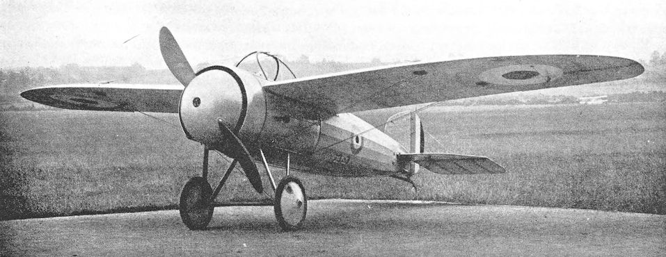
Bristol M.1A. This illustration shows the original cabane structure which consisted of two half-hoops of steel tubing.
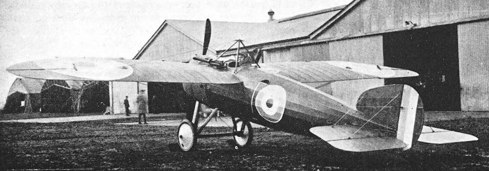
Bristol M.1B. In this photograph, the pyramidal cabane and the offset Vickers gun can be seen. The aeroplane is A.5139.
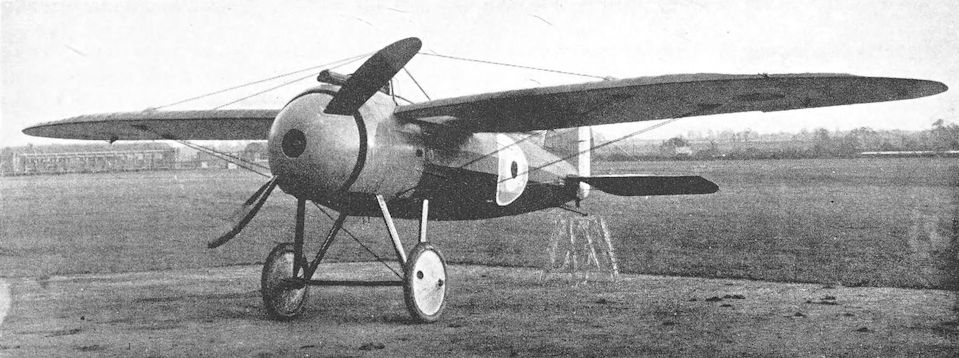
Bristol M.1C, C.4910. Note centrally-mounted Vickers gun and cut-out in port wing root.
The tenth of the M.1C production batch built for the RFC being illustrated here. These were used principally in the Middle East.
The tenth of the M.1C production batch built for the RFC being illustrated here. These were used principally in the Middle East.
Bristol S.2A
THE lack of a British synchronising gear for machine-guns resulted in the appearance of some peculiar aeroplanes in the early stages of the war. Usually the compromise which had to be adopted in order to provide reasonably effective armament had a catastrophic effect upon performance.
The Bristol S.2A was a reasoned attempt to produce a two-seat scouting aeroplane with the speed of a single-seater but capable of defending itself while yet remaining under the full control of its pilot. The aeroplane was a small side-by-side two-seater biplane; the passenger was responsible for firing the defensive armament.
The machine was a development of the Scout D. In fact, it had the same wings and tail-unit as the single-seater. The fuselage was wide enough to accommodate the two occupants side-by-side, and the centre-section was correspondingly wider than that of the Scout D. The engine was the 110 h.p. Clerget, which proved to be somewhat troublesome.
Two prototypes were built in May and June, 1916, and the type proved to be quite fast and manoeuvrable under test. Production was not undertaken, for interrupter gears had meanwhile become available.
One of the S.2As was later used at Gosport, where it was fitted with a 100 h.p. Gnome Monosoupape and was flown with a modified engine cowling. There was no cowling below the level of the airscrew shaft, and three large apertures were cut in the upper portion.
SPECIFICATION
Manufacturers: The British & Colonial Aeroplane Co., Ltd., Filton and Brislington, Bristol.
Power: 110 h.p. Clerget; 100 h.p. Gnome Monosoupape.
Dimensions: Span: 28 ft 2 in. Length: 21 ft 3 in. Height: 10 ft. Chord: 4 ft 6 in. Span of tail: 10 ft.
Weights: Loaded: 1,400 lb.
Performance: Maximum speed: 95 m.p.h.
Production: Two prototypes were built under Contract No. 87/A/372.
Serial Numbers: 7836-7837.

The first prototype S.2A, 7836, with 110hp Clerget engine.
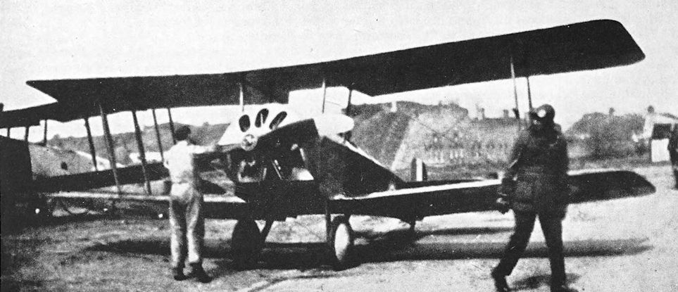
Bristol S.2A with 100 h.p. Gnome Monosoupape engine, photographed at Gosport.
Bristol T.T.A
SOON after the outbreak of war, it was realised that aerial combat was not only a possibility but an accomplished fact; and ways had to be sought to provide aircraft combining performance with effective fire power.
In September, 1915, Frank Barnwell, assisted by L. G. Frise, began work on the design of a twin-engined two-seat fighter which was designated Bristol T.T., or Twin Tractor. Two engines were considered necessary to achieve a worthwhile performance, and the original design was for two 150 h.p. R.A.F. 4a engines. The gunner had two free Lewis guns, and occupied the nose cockpit from which he had a wide field of fire. The pilot sat behind the wings, and a single Lewis gun firing aft was provided for his use. Dual control was provided. The tail unit was generally similar in appearance to that of the Bristol Scout, and there were enormous ailerons.
Petrol was carried in three main tanks in the fuselage, and pressure feed to the engines was maintained by a fan-driven pump. Two further tanks were fitted, one behind each engine. These were intended to be gravity tanks but were converted to pressure tanks.
By the time the T.T. was ready for construction the output of R.A.F. 4a engines had been earmarked for B.E.12s. The Bristol design was therefore modified to have two Beardmore engines of either 120 h.p. or 160 h.p. Only the lower-powered engines became available, however, and the completed aircraft, re-designated T.T.A., was tested in May, 1916, by Captain Hooper, R.F.C. The engines turned in opposite senses.
Later in May the T.T.A. went to Upavon to undergo official trials. Because it was underpowered its performance was not good; and it was adversely criticised on several grounds, but principally on the poor outlook from the pilot’s cockpit and the impossibility of fitting rearwards-firing guns. There was no kind of intercommunication between pilot and gunner; and the fuel system and poor lateral control were the subjects of adverse criticism.
By the time the T.T.A. had flown, interrupter gears had become available, and Captain Barnwell was already looking ahead to the design which was to develop into the Bristol Fighter. There were therefore no misgivings over the abandonment of the T.T.A.
The projected Bristol F.3A incorporated the wings, tailplane and rear fuselage of the T.T.A. The F.3A was designed to the same specification as the Armstrong Whitworth F.K.12, Sopwith LRTTr and Vickers F.B.11; and, like them, it was to have had the 250 h.p. Rolls-Royce engine. Two gunners were to have been accommodated in two cockpits mounted on the upper wing.
SPECIFICATION
Manufacturers: The British & Colonial Aeroplane Co., Ltd., Filton, Bristol.
Power: Two 120 h.p. Beardmore. Engines Nos. 2713F (starboard) and 3239F (port).
Dimensions: Span.: 53 ft 6 in. Length: 39 ft 2 in. Height: 12 ft 6 in. Chord: 8 ft. Gap: 7 ft 10 1/2 in. Stagger: 11-8 in. Dihedral: 4°. Incidence: 2°. Span of tail: 17 ft 8 in. Airscrew diameter: 8 ft 11 in.
Areas: Wings: 817 sqft. Tailplane: 81 sq ft. Elevators: 47 sq ft. Rudder: 33 sq ft.
Weights and Performance: No. of Trial Report: M.37. Date of Trials: May 23rd and 24th, 1916. Place of trials: Central Flying School, Upavon. Airscrews used on trial: Type No. P.2359; maker’s series numbers B. & C. 2495 and 2498.
Weight empty: 3,820 lb. Military load: 100 lb. Crew: 320 lb. Fuel and oil: 860 lb. Weight loaded: 5,100 lb. Maximum speed at ground level: 86-7 m.p.h.; at 2,000 ft: 85-8 m.p.h.; at 4,000 ft: 85-3 m.p.h.; at 6,000 ft: 85-6 m.p.h.; at 8,000 ft: 85 m.p.h. Climb to 1,000 ft: 3 min; to 2,000 ft: 6 min 45 sec; to 3,000 ft: 10 min 8 sec; to 4,000 ft: 13 min 30 sec; to 5,000 ft: 17 min 15 sec; to 6,000 ft: 21 min; to 7,000 ft: 25 min 52 sec; to 8,000 ft: 32 min 15 sec; to 9,000 ft: 39 min 45 sec; to 10,000 ft: 53 min 15 sec. Service ceiling: 9,500 ft.
Tankage: Petrol: three main pressure tanks 93 gallons; two service pressure tanks 11 gallons each; total 115 gallons. Oil: 9 gallons. Water: 10 gallons.
Armament: Two free Lewis machine-guns. One was fired by the gunner in the nose cockpit, the other by the pilot.
Production: Two prototypes were built under Contract No. 87/A/330.
Serial Numbers: 7750-7751.

The Bristol T.T.A. provided a clear field of fire for a pair of Lewis guns in the front cockpit.
Bristol M.R.1
WHILE the prototypes of the Bristol F.2A were still under construction, the British & Colonial Aeroplane Co. were asked to design a similar machine of all-metal construction, with a particular view to operations in or near the tropics where that form of construction would have considerable advantages over the conventional wire-braced wooden structures of the time.
The preliminary general layout was sketched by Frank Barnwell in July, 1916, but the development of the design was carried out by W. T. Reid. The completed design was known as the Bristol M.R.1.
In a general way, the M.R.1 resembled the F.2A: the fuselage was mounted midway in the gap between the wings; the lower centre-section was an open cross-braced structure; and the crew were accommodated close together. The fabric-covered wings were of orthodox appearance, but were of all-steel construction and were built by the Steel Wing Co. of Cheltenham. However, the first machine (A.5177) was delivered with wooden wings.
The fuselage was built in four sections, bolted together, but the basic structure was a wire-braced box girder made of steel tubing. The fuselage was covered with aluminium sheet which was strengthened locally by corrugated sheet aluminium riveted to the inside. This method of construction produced a smooth outer covering, but no attempt was made to work double curvature of the skin and, as a result, the M.R.1 had rather more severe lines than the F.2A. Interplane and undercarriage struts were of steel tubing.
Two prototypes were built, and were powered by the 150 h.p. Hispano-Suiza engine. Captain Barnwell flew the first a good deal for experimental purposes, and ultimately crashed it by flying it into a tree. The second machine (A.5178) was sent to the Aeronautical Inspection Directorate at Kingsway, and thereafter underwent static tests. This machine latterly bore the number A.58623 on its fuselage: this was not a genuine serial number, and the aeroplane was not flown with it.
At one time it was intended to fit the M.R.1 with wings built on the Mayrow principle, which embodied components of aluminium alloy, but it is uncertain whether this was ever done. A pair of Mayrow wings were made and were submitted for structural test, however.
SPECIFICATION
Manufacturers: The British & Colonial Aeroplane Co., Ltd., Brislington, Bristol.
Power: 150 h.p. Hispano-Suiza. Engine No. W.D.10109 was fitted to the first M.R.1, A.5177.
Dimensions: Span: 42 ft 2 in. Length: 27 ft. Height: 10 ft 3 in. Chord: 6 ft. Gap: 5 ft 11 in. Stagger: nil. Dihedral: 3° 30'. Incidence: 0°. Span of tail: 16 ft 3 in. Airscrew diameter: 8 ft 10 in.
Areas: Wings: upper 235 sq ft, lower 223 sq ft, total 458 sq ft. Ailerons: each 14-75 sq ft, total 59 sq ft. Tailplane: 27-8 sq ft. Elevators: 30 sq ft. Fin: 7-8 sq ft. Rudder: 8-25 sq ft.
Weights: Empty: 1,700 lb. Military load: 270 lb. Crew: 360 lb. Fuel and oil: 480 lb. Weight loaded: 2,810 lb.
Performance: Maximum speed at ground level: 110 m.p.h.; at 5,000 ft: 106 m.p.h.; at 10,000 ft: 98 m.p.h.
Climb to 5,000 ft: 8 min; to 10,000 ft: 20 min.
Tankage: Petrol: 50 gallons. Oil: 5 gallons.
Armament: One fixed Vickers machine-gun mounted centrally in a tunnel under the cowling, and synchronised to fire forward through the revolving airscrew; one Lewis machine-gun on Scarff ring-mounting on rear cockpit.
Production: Two prototypes were built under Contract No. 87/A/865.
Serial Numbers: A.5177-A.5178. The latter aircraft bore the number A.58623 at a later stage.

A Bristol Type 13 M.R.1 (originally A5177), fitted with the metal wings and carrying the spurious number A58623 al the time of ground tests at Filton in 1918.
Bristol Braemar
CAPTAIN BARNWELL made his preliminary designs for a large triplane bomber as early as November, 1917, when it was made known that bombing attacks on Berlin were to be carried out from bases in England as soon as aircraft were available which were capable of doing so.
The original conception was of a large triplane with a fuselage of good aerodynamic form incorporating a central engine room in which four engines were to be installed. Two outboard tractor airscrews were to be driven by shafts and gearing. Internal stowage for six 250-lb bombs was envisaged, and petrol for a range of at least 1,000 miles was to be carried.
Development of the design was entrusted to W. T. Reid, for Barnwell wished to devote his attention to the two-seat fighter which was to become the Badger. The bomber design was progressively modified, and was considerably different from Barnwell’s original layout by the time a contract for three prototypes was awarded.
The machine as built was named Braemar, and in order to test the airframe without delay the first prototype was fitted with four 230 h.p. Siddeley Puma engines mounted on the centre mainplane in two back-to-back pairs. The basic structure was of wood with the usual wire bracing. The fuselage was covered with plywood, and not the least remarkable feature of the Braemar was the fact that the wings could be folded. It was much larger than any other aeroplane built at Filton up to that date: its dimensions prevented the assembly of more than one machine at a time. The final assembly had to be carried out in a hangar at the aerodrome, and the first Braemar was completed during the summer of 1918. The test flying was done by F. P. Raynham, and the machine underwent official trials at Martlesham Heath in September, 1918. The official report mentions a certain amount of vibration in the fuselage, and modifications were made to the undercarriage. The second Braemar, C.4297, had the improved undercarriage.
The second machine was powered by four Liberty 12 engines, and was designated Braemar Mk. II. It did not fly until February 18th, 1919, and arrived too late to be ordered in quantity. Its performance was good, and it might well have proved to be an efficient bomber if the war had lasted longer.
The Braemar Mk. II was at Martlesham Heath in July, 1919, and apparently remained there until the following year. On test, its fuel system proved to suffer from a defect similar to that of the D.H.10: at low air speeds the wind-driven pumps failed to maintain an adequate supply of fuel.
The third airframe was not completed as a Braemar but, with a completely re-designed fuselage, emerged in 1920 as the Bristol Pullman, a commercial machine which provided enclosed accommodation for fourteen passengers in considerable luxury.
SPECIFICATION
Manufacturers: The British & Colonial Aeroplane Co., Ltd., Filton, Bristol.
Power: Braemar Mk. I: four 230 h.p. Siddeley Puma. Engine Nos.: port front 6406.24080; port rear 6394.24068; starboard front 6399.24073; starboard rear 6368.24042. Braemar Mk. II: four 400 h.p. Liberty 12 (built by the Lincoln Motor Co.). Engine Nos.: port front 18020/601, W.D. No. 62068; port rear 18018/609, W.D. No. 62067; starboard front 18022/608, W.D. No. 62069; starboard rear 26172/2768, W.D. No. 65326.
Dimensions: Span: top and centre 81 ft 8 in., bottom 78 ft 3 in. Length: 51 ft 6 in. Height: 20 ft 8 in. Chord: 8 ft 6 in. Gap: both 7 ft 2 1/2 in. Stagger: nil. Sweepback: 6° 30'. Dihedral: 2°. Incidence: 2° 30'. Airscrew diameter: front, Mk. I 9 ft 10 in.; Mk. II 10 ft; rear, Mk. I 9 ft 2 1/4 in.; Mk. II 9 ft 6 in. Tyres: Mk. I, 900 X 200 mm; Mk. II, 1100 X 220 mm.
Areas: Wings: top 650 sq ft, middle 650 sq ft, bottom 605 sq ft, total 1,905 sq ft. Ailerons: each 48 sq ft, total 192 sq ft. Tailplanes: upper 51-5 sq ft, lower 45 sq ft, total 96-5 sq ft. Elevators: upper 42-5 sq ft, lower 42-5 sq ft, total 85 sq ft. Fins: two of 11-4 sq ft and one 5-2 sq ft, total 28 sq ft. Rudders: two of 7-6 sq ft and one 10-2 sq ft, total 25-4 sq ft.
Weights (lb) and Performance:
Braemar Mk. I Braemar Mk. I Braemar Mk. II
With 6 X 112-lb bombs With 5,000 lb load With 2,500 lb load
No. of Trial Report M.233a M.233a M.271c
Date of Trial Report September to September to February nth,
October, 1918 October, 1918 1920
Type of airscrew used on trial:
front P.3060 P.3060 A.B.22699
rear P.3065 P.3065 P.3084
Weight empty 9.578 9.578 11,208
Military load 345 305 828
Crew 720 540 680
Fuel and oil 3.635 1.355 3.496
Water 300 300 300
Weight loaded 14.578 12,078 16,512
Maximum speed (m.p.h.) at
5,000 ft 103-5 107 -
5,650 ft - - 122
6,500 ft 101 105-5 -
10,000 ft 95 101-5 -
13,000 ft - 98-5 -
14,400 ft - - 107-5
m. s. m. s. m. s.
Climb to
1,000 ft 1 50 1 20 1 00
2,000 ft 3 55 2 45 2 05
3,000 ft 6 10 4 15 3 15
4,000 ft 8 35 5 55 4 30
5,000 ft 11 15 7 35 5 55
6,000 ft 14 10 9 30 7 25
7,000 ft 17 35 11 35 9 00
8,000 ft 21 25 13 50 10 50
9,000 ft 26 05 16 25 12 50
10,000 ft 31 40 19 15 15 05
11,000 ft 38 50 22 30 17 40
12,000 ft - - 26 20 20 50
13,000 ft - - 30 50 24 30
14,000 ft - - - - 29 25
15,000 ft - - - - 36 20
Absolute ceiling (feet) 14,000 17.500 17,000
Tankage: Braemar Mk. I. Petrol: four main tanks in fuselage: two port tanks of 107 gallons each, starboard front tank 103 gallons, starboard rear tank 105 gallons; two gravity tanks of 14 gallons each in top wing; total 450 gallons. Oil: four tanks, two between each pair of engines, 11 gallons in each; total 44 gallons. Water: 30 gallons. Braemar Mk. II. Petrol: four main tanks in fuselage, each of 105 gallons; two gravity tanks, each of 14 gallons, in top wing; total 448 gallons. Oil: four tanks, total 41 1/2 gallons. Water: 30 gallons.
Armament: Racks for six 230-lb bombs were provided, and up to five Lewis machine-guns could be carried as follows: two on Scarff ring-mounting on nose cockpit, two on rocking-post mountings in dorsal cockpit aft of wings, one on Scarff ring-mounting on floor of fuselage aft of wings.
Production: Two Braemars were built, one Mk. I and one Mk. II. The third airframe was completed as the Bristol Pullman.
Serial Numbers: C.4296-C.4298: ordered under Contract No. A.S.38907. C.4296: Braemar Mk. I; C.4297: Braemar Mk. II; C.4298: completed as Bristol Pullman.

A view of the Braemar Mk I, C4296, powered by 230hp Siddeley Puma engines, which emphasises its great height and tiny undercarriage.

Bristol Braemar Mk. II C4297 with Liberty engines.
Bristol Scout F and F.1
IN the design of the Bristol Scout F, Captain Barnwell gave further evidence of advanced thinking. Work on the design began in June, 1917, but the aeroplane would not have been accounted old-fashioned more than a decade later.
In an age when most liquid-cooled aero-engines had their radiators installed car-fashion as a vertical surface immediately behind the airscrew, the Scout F represented a complete breakaway from contemporary practice with its radiator mounted under the fuselage. This position of the radiator allowed the cowling of the engine to be made commendably clean, and the aerodynamic entry of the aeroplane was unusually good.
Structurally the Scout F was fairly typical of its period. The rear portion of the fuselage was a conventional wire-braced fabric-covered wooden structure, while the forward section was a plywood-covered box girder. The wings were of unequal span and chord, and both interplane and centre-section struts were of N configuration, thus eliminating the more usual incidence wires. Ailerons were fitted to the upper wings only.
In the air the Scout F had excellent handling qualities, and was considered to be superior to the S.E.5a in some respects. Its performance was good, but it had a built-in liability in its Sunbeam Arab engine. When the Scout F was designed, it was not known that the Arab was going to prove so incurably unsatisfactory. All the troubles experienced with this engine in the Bristol Fighter were repeated with the Scout F, and there can be little doubt that the Arab was the chief reason why the machine did not go into production. Vibration was so severe that damage was caused to the engine bearers.
Serial numbers were allotted for six machines, but in fact only three were completed and construction of a fourth did not proceed beyond the making of the bare airframe. The design was so promising that the British & Colonial Company did not wish to abandon it completely, and therefore sought an alternative power unit.
The opportunity was taken to fit the Scout F with a new and untried radial engine, the Cosmos Mercury. This engine had been designed to fulfil the Air Board specification known as Scheme A, which had been issued on April 5th, 1917. Inspired by the Admiralty, Scheme A called for a stationary air-cooled radial engine not more than 42 inches in diameter and capable of delivering at least 300 h.p.
Designs were submitted by Brazil, Straker & Co., Ltd., of Fishponds, Bristol, by Siddeley-Deasy, by Vickers, and by A.B.C. Motors Ltd. The winning design was the fourteen-cylinder two-row radial submitted by Brazil, Straker & Co., Ltd., and a production order for 200 engines was placed. The engine was named Mercury, and was designed by L. F. G. Butler, Brazil Straker’s chief designer, under the direction of A. H. R. (later Sir Roy) Fedden, who was the company’s chief engineer.
The design of the Mercury was completed in July, 1917, and the first bench run was made early in 1918. At about that time the Brazil, Straker concern changed hands and was renamed the Cosmos Engineering Company.
The Cosmos Mercury, as the engine was now known, was flown for the first time in April, 1918, installed in the third Bristol Scout F airframe, B.3991. With this engine the aircraft was designated Scout F.1. Despite the completely different configuration of the Mercury engine, care was again taken to keep drag down to a minimum. The day of the Townend ring and low-drag cowling had not yet arrived, but the Mercury was provided with a circular cowling through which the cylinder heads protruded.
The performance of the Scout F.1 was excellent, particularly in rate of climb, but it was too late upon the scene to be considered for production. Moreover, the Cosmos company decided in the autumn of 1918 to concentrate on the development of their new single-row radial engine, the Jupiter, and the Mercury was virtually shelved. When the Armistice was signed, the contract for the 200 engines was cancelled, but testing continued into 1919. In April of that year the Bristol Scout F.1 set new climbing records when it reached 10,000 feet in 5-4 minutes and 20,000 feet in 16-25 minutes.
SPECIFICATION
Manufacturers: The British & Colonial Aeroplane Co., Ltd., Filton and Brislington, Bristol.
Power: Scout F: 200 h.p. Sunbeam Arab II. Scout F.1: 347 h.p. Cosmos Mercury.
Dimensions: Span: upper 29 ft 7 1/2 in., lower 26 ft 2 in. Length: Scout F, 20 ft 10 in.; Scout F.1, 20 ft. Height: 8 ft 4 in. Chord: upper 5 ft 7 in., lower 4 ft 11 in. Gap: 5 ft 1 in. Stagger: 2 ft. Dihedral: 0°. Incidence: 1°. Span of tail: 10 ft 6 in. Airscrew diameter: Scout F, 9 ft 2 in.
Areas: Wings: upper 150 sq ft, lower i 10 sq ft, total 260 sq ft. Ailerons: each 15-25 sq ft, total 30-5 sq ft. Tailplane: 15 sq ft. Elevators: 14-5 sq ft. Fin: 4-1 sq ft. Rudder: 5-3 sq ft.
Weights and Performance: No. of Trial Report on Scout F: M.185. Date of Report: March, 1918. Type of airscrew used on trial of Scout F: P.3041. Scout F: weight empty: 1,436 lb. Military load: 319 lb. Pilot: 180 lb. Fuel and oil: 275 lb. Weight loaded: 2,210 lb. Scout F.1: weight loaded: 2,260 lb. Scout F: maximum speed at ground level: 138 m.p.h.; at 5,000 ft: 135 m.p.h.; at 10,000 ft: 128-5 m.p.h.; at 15,000 ft: 117-5 m.p.h. Climb to 6,500 ft: 5 min 20 sec; to 10,000 ft: 9 min 20 sec; to 15,000 ft: 17 min 20 sec. Service ceiling: 21,000 ft. Scout F.1: maximum speed at ground level: 145 m.p.h. Climb to 10,000 ft: 5 min 25 sec; to 20,000 ft: 16 min 15 sec.
Tankage: Scout F. Petrol: main tank 29 1/2 gallons; service tank 3 gallons; total 32 1/2 gallons. Oil: 5 gallons. Water: 1 1/2 gallons.
Armament: Two fixed Vickers machine-guns mounted on top of the fuselage and synchronised to fire forward through the revolving airscrew.
Production: Three Scouts F were completed, and a fourth airframe was built. They were ordered under Contract No. A.S.3423.
Serial Numbers: B.3989-B.3994. B.3991 was modified to become the Scout F.1; only the airframe of B.3992 was built; B.3993 and B.3994 were not built.
Bristol F.2C, the Badger
DESPITE the great success achieved by the Bristol F.2B Fighter, Captain Barnwell was not content to rest upon his laurels. It had been realised that sooner or later a better aeroplane would be required as a replacement for the redoubtable Bristol Fighter and, to meet the new requirements, he began work on the design of a two-seat fighter, designated Bristol F.2C, in November, 1917.
The original design was for a biplane powered by either a 230 h.p. Bentley B.R.2 engine or a 260 h.p. Salmson water-cooled radial, and deliberately designed to be easily produced in large quantities. However, neither of these power units was sufficiently powerful to give the required performance, but early in 1918 it seemed that the new A.B.C. Dragonfly radial engine held out great promise of high power for low weight, and Captain Barnwell, like so many contemporary designers, decided to use it for his new two-seat fighter.
He produced a completely new design based on the Dragonfly, and it was this aeroplane which was built under the designation F.2C and named Badger. The initial order was for three prototypes numbered F.3495 - F.3497.
The first machine, Badger Mk. I, was built with the Dragonfly engine and appeared in two forms: at first without spinner and with a more or less hemispherical cowling over the front of the engine, and later with a small spinner, more pointed cowling, and modified rudder. The first Badger crashed on February 4th, 1919. An air-lock in the fuel-line caused engine failure, and the undercarriage and engine installation were destroyed when the machine struck the ground. The second Badger was fitted with the new 450 h.p. Cosmos Jupiter nine-cylinder radial engine, and had a re-designed vertical tail incorporating a fixed fin; it was named Badger Mk. II. The third prototype was not built.
Design of the Jupiter engine had begun early in 1918, almost immediately after Brazil, Straker & Co. had been renamed the Cosmos Engineering Co. As soon as the preliminary design was complete, A. H. R. Fedden submitted a sketch to the Air Board and in July, 1918, received an informal intimation of official interest in the proposed engine. By autumn, 1918, the Cosmos company were so convinced of the Jupiter’s superiority that they decided to concentrate on its development at the expense of the earlier Mercury engine. Designs were completed for two versions of the Jupiter: one was a direct-drive engine, the other had a planetary reduction gear.
Soon after the cancellation of the contract for the 200 Cosmos Mercuries, the Government placed an order for six Jupiters. The first direct-drive Jupiter had been completed in October, 1918, and made its first bench run shortly before the Armistice. Its air tests were carried out in the Badger Mk. II during 1919, and ultimately it became the first engine to pass the new (in 1920) official 50-hour type test. By then the cost of developing the Jupiter had broken the Cosmos company, whose assets and patents were taken over in August, 1920, by the Bristol Aeroplane Company, who had been strongly pressed to do so by the Government.
Despite early misgivings experienced by the Bristol company, the Jupiter was developed into an excellent power unit, and its development continued for many years.
It is as a flying test-bed for the Jupiter that the Badger is best remembered. Badger F.3496 was flown as a simple two-seater with the Scarff ring removed from the rear cockpit and the side apertures glazed over, but later another Jupiter-powered Badger was built under a separate contract. This was numbered J.6492, and was fully equipped as a two-seat fighter with twin Vickers guns for the pilot and a Scarff ring for the observer. At first the rudder on this machine was identical to that of F.3496, but a balanced rudder was later fitted. The ailerons on J.6492 were balanced by small superimposed aerofoils in the same fashion as those of the Avro Manchester. This last Badger had a variety of engine cowlings during its career.
SPECIFICATION
Manufacturers: The British & Colonial Aeroplane Co., Ltd., Filton, Bristol.
Power: Badger I: 320 h.p. A.B.C. Dragonfly I. Badger II: 450 h.p. Cosmos Jupiter.
Dimensions: Span: upper 36 ft 9 in., lower 31 ft 4 in. Length: 23 ft 8 in. Height: 9 ft 1 in. Chord: upper 6 ft 2 in., lower 5 ft 6 in. Dihedral: 2°.
Areas: Wings: 357-2 sq ft.
Weights and Performance: No. of Trial Report on Badger I: M.263. Date of Report: September, 1919. Type of airscrew used on trial: P.3086. Weight empty: 1,948 lb. Military load: 334 lb. Crew: 360 lb. Fuel and oil: 510 lb. Weight loaded: 3,152 lb. Performance (with Dragonfly engine): maximum speed at ground level: 135 m.p.h.; at 6,500 ft: 131 m.p.h.; at 10,000 ft: 129 m.p.h.; at 15,000 ft: 122 m.p.h. Climb to 6,500 ft: 6 min 20 sec; to 10,000 ft: 11 min; to 15,000 ft: 20 min 30 sec. Service ceiling: 20,600 ft. (With Jupiter engine) Maximum speed at ground level: 142 m.p.h.
Armament: Two fixed forward-firing Vickers machine-guns, synchronised to fire through the revolving airscrew; and one Lewis machine-gun on Scarff ring-mounting on the rear cockpit.
Production: Three Badgers were built.
Serial Numbers: F.3495-F.3497: ordered under Contract No. 35A/1122/C.994. (F.3497 was not built.) J.6492: ordered under Contract No. 35A/3312/C.3844.
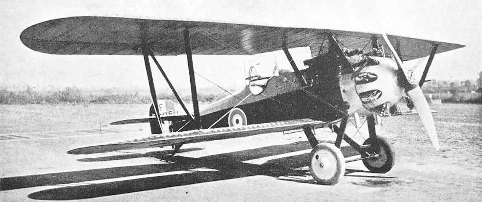
The first Bristol Badger, F.3495, with the original installation of the A.B.C. Dragonfly engine and original rudder.
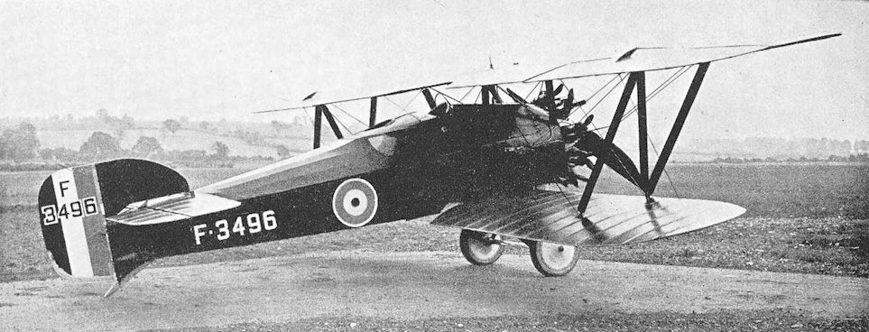
The second Badger, F.3496, with 400 h.p. Cosmos Jupiter engine.
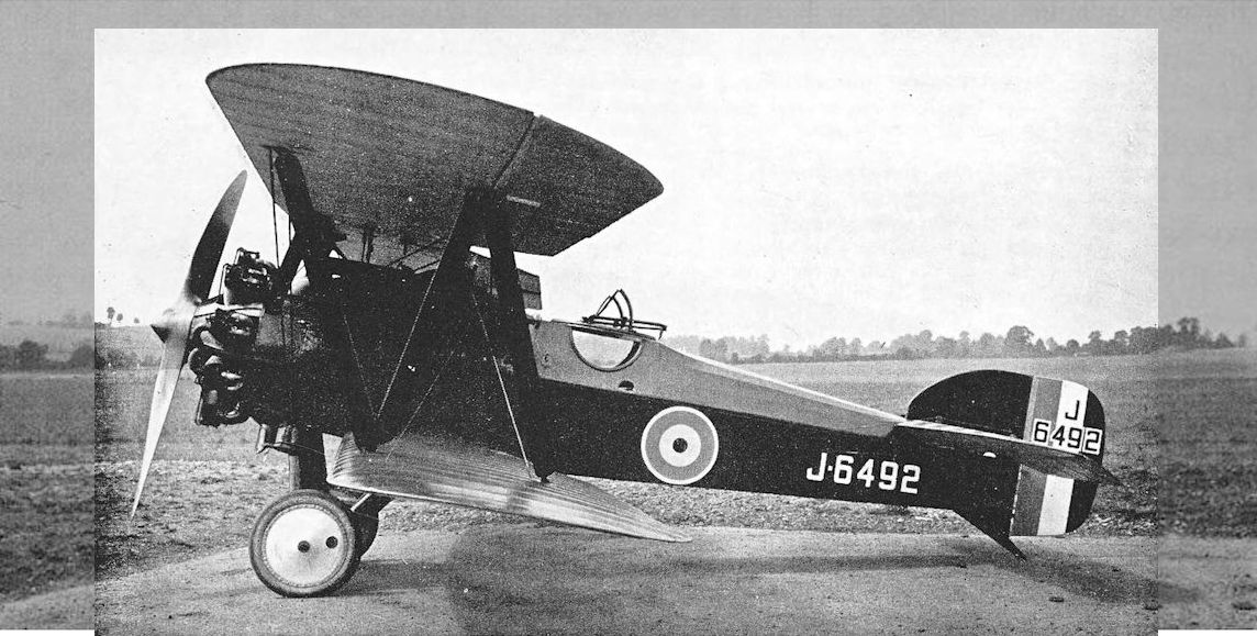
The third Badger, J.6492, with 400 h.p. Cosmos Jupiter I engine and its original rudder.
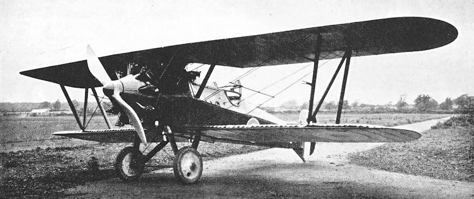
The third Badger, J.6492, with 400 h.p. Cosmos Jupiter I engine and its original rudder.
de Havilland 1 and 1A
THE Aircraft Manufacturing Company was established by G. Holt Thomas early in 1912. The company held the British rights for the manufacture of Farman aeroplanes, and was content to build them for a time; but Holt Thomas wanted to establish a design department in the firm, and in June, 1914, he secured the services of Geoffrey de Havilland.
Mr de Havilland (now Sir Geoffrey) came to the Aircraft Manufacturing Co. with a wealth of experience of aircraft design and construction. Not only had he designed and flown the Royal Aircraft Factory’s most successful types during his period of service there, but he had also seen many examples of the products of other manufacturers which had gone to Farnborough to be tested. For the Aircraft Manufacturing Co. he designed a series of remarkably good aeroplanes, several of which made substantial contributions towards the attainment of supremacy in the air for the Allies. These aircraft earned for their designer the unique compliment of being known by his name rather than by that of the manufacturer: the numerical D.H. designations were seldom prefaced by “Airco”.
The D.H. 1 was not Geoffrey de Havilland’s first design by any means, but it was the first aeroplane designed by him for the Aircraft Manufacturing Co. It was intended for reconnaissance and fighting duties, and the lack of a machine-gun interrupter gear inevitably made it a two-seat pusher biplane. It was powered by a 70 h.p. Renault engine, and appeared in January, 1915. The forward cockpit was occupied by the observer-gunner, who had a good field of fire in all forward directions. The wings were of two-bay construction, and the tail unit was supported on the customary tail-booms. The undercarriage of the prototype incorporated coil springs and concealed oleo-struts, and when it first appeared the D.H.1 was fitted with air-brakes. These consisted of two small aerofoils, each of about 3 feet span, disposed one on either side of the nacelle and pivoted on an axis which crossed the fuselage just behind the forward centre-section struts; they could be rotated through 90° to present a flat surface to the airstream. The air-brakes were not successful, however, and were soon abandoned.
The test flights were made by Geoffrey de Havilland himself, and the D.H.1 had quite a good performance, despite the fact that it had been designed for a more powerful engine. The intention was to fit the 120 h.p. Beardmore as the standard power unit, but the Royal Aircraft Factory had laid claim to the few Beardmores which were available in 1914, and production of the D.H. design was delayed. Some were built with the Renault engine: these differed from the prototype in having exhaust manifolds which led the gases well forward, presumably to avoid damage to the airscrew. In the production machines the forward cockpit was cut much lower than on the prototype in order to facilitate the use of a gun, and the undercarriage relied on the more usual rubber cord for shock-absorption.
When powered by the Beardmore engine the aircraft was re-designated D.H.1A, and was identical in appearance to the production D.H.1s apart from the bulkier upright engine with its radiator behind the pilot’s cockpit.
By the time production could be undertaken, the Aircraft Manufacturing Co. were too busy with later designs, and the D.H.1A was built by Savages of King’s Lynn under sub-contract. The type never achieved any prominence; comparatively few were built, and only six went overseas. These went to the relative obscurity of the Middle East, and the others were distributed to Home Defence and training units. However, the D.H.1 design is of historic interest, not only as the first of the long line of distinguished D.H. types which was continued after the demise of the Aircraft Manufacturing Co., but also as the immediate predecessor of the more famous D.H.2.
SPECIFICATION
Manufacturers: The Aircraft Manufacturing Co., Ltd., Hendon, London, N.W.
Other Contractors: Savages, Ltd., King’s Lynn, Norfolk.
Power: D.H.1: 70 h.p. Renault. D.H.1A: 120 h.p. Beardmore.
Dimensions: Span: 41 ft. Length: D.H.1, 28 ft 11 5/8 in.; D.H.1A, 28 ft 11 1/4 in. Height: D.H.1, 11 ft 4 m.; D.H.1A, 11 ft 2 in. Chord: 5 ft 6 in. Gap: 5 ft 7 in. Stagger: nil. Dihedral: 3°. Incidence: D.H.1, 4° 30'; D.H.1A, 5° 15'. Span of tail: D.H.1, 12 ft 5 1/2 in.; D.H.1A, 12 ft 3 in. Wheel track: 5 ft 9 3/4 in. Airscrew diameter: D.H.1, 9 ft 0-4 in.; D.H.1A, 8 ft 10-3 in.
Areas: Wings: upper 187 sq ft, lower 175-25 sq ft, total 362-25 sq ft. Ailerons: each 16 sq ft, total 64 sq ft. Tailplane: 37-5 sq ft. Elevators: 23 sq ft. Fin: 3-7 sq ft. Rudder: 15-4 sq ft.
Weights (in lb):
Empty Military load Crew Fuel and Oil Loaded
D.H.1: 1.356 60 360 268 2,044
D.H.1A: 1,610 40 360 330 2,340
Performance: D.H.1: maximum speed at 3,500 ft: 80 m.p.h. Climb to 3,500 ft: 11 min 15 sec. D.H.1A: maximum speed at ground level: 90 m.p.h.; at 2,000 ft: 89 m.p.h.; at 4,000 ft: 88 m.p.h.; at 6,000 ft: 90 m.p.h.; at 8,000 ft: 90 m.p.h.; at 10,000 ft: 86 m.p.h.; at 12,000 ft: 84 m.p.h. Climb to 1,000 ft: 1 min. 40 sec; to 2,000 ft: 3 min 35 sec; to 3,000 ft: 5 min 55 sec; to 3,500 ft: 6 min 27 sec; to 4,000 ft: 8 min 15 sec; to 5,000 ft: 10 min 25 sec; to 6,000 ft: 13 min 10 sec; to 7,000 ft: 16 min 20 sec; to 8,000 ft: 19 min 30 sec; to 9,000 ft: 23 min; to 10,000 ft: 27 min 30 sec; to 11,000 ft: 32 min 25 sec; to 12,000 ft: 38 min 25 sec. Service ceiling 13,500 ft.
Tankage: D.H.1: petrol 30 gallons. D.H.1A: petrol, main pressure tank, 35-3 gallons; service gravity tank, 5-5 gallons; total 40-8 gallons. Oil: 2-3 gallons. Water: 5 gallons.
Armament: One Lewis machine-gun on pillar mounting in front cockpit.
Service Use: No unit was completely equipped with D.H.1s or 1As. The type was issued to some Home Defence and training units, including No. 35 Reserve Squadron, Northolt. Six went to the Middle East Brigade in 1916, where some were used operationally by No. 14 Squadron, R.F.C.
Production and Allocation: The total number of D.H.is and iAs delivered to the R.F.C. was seventy-three. Of that total, forty-three went to training units, twenty-four to Home Defence units, and six to the Middle East Brigade.
Serial Numbers: 4606, 4607, 4615. A.1611-A.1660.
Costs:
Airframe, without engine, instruments and gun £1,100 0s.
70 h.p. Renault engine £522 10s.
120 h.p. Beardmore engine £825 0s.

Первый экземпляр DH.1
D.H.1 prototype with air-brakes removed.
D.H.1 prototype with air-brakes removed.

Production D.H.I, serial number 4607, with 70 h.p. Renault engine.

de Havilland 1A.
de Havilland 2
THE second de Havilland design which was built by the Aircraft Manufacturing Co. was a small single-seat fighting scout in which the designer’s first concern had been to give the pilot effective forward-firing armament. This, in the days before machine-gun interrupter gears, almost automatically meant a pusher aircraft; and as such the D.H.2 looked very much like a scaled-down D.H.1.
Some histories seem to imply that the D.H.2 was deliberately designed and produced as a counter-weapon to the Fokker Monoplane, which, with its synchronised machine-gun, wrought great havoc among the Allied two-seaters in late 1915 and early 1916. In point of fact, the design of the D.H.2 was neither demanded nor prompted by the Fokker menace any more than was that of its companion Fokker-beater, the Royal Aircraft Factory F.E.2b: it simply so happened that these aeroplanes proved to be effective counter-weapons. The prototype D.H.2 completed its flight trials in July, 1915, at the time when the Fokker Monoplane was only beginning to be encountered; the first contract for quantity production was awarded during the following month, and the first production machine arrived in France in December, 1915.
When the D.H.2 was designed, the technique of using a fixed gun and aiming the whole aeroplane at the target was not at first accepted by Britain, although it had been successfully demonstrated by French pilots. The prototype D.H.2 did not have a fixed machine-gun, nor even a central mounting for a semi-free weapon: instead, a movable bracket was fitted on each side of the cockpit in line with the windscreen, and from these the pilot was expected to aim his Lewis gun while flying his aircraft in the manoeuvres of combat. As a result, the nacelle of the prototype had a rather different appearance from that of the production D.H.2.
For a pusher, the D.H.2 was remarkably neat and compact, and was of great structural strength. It was a two-bay biplane, and the tail-booms formed a V in plan; the tail-unit was obviously inherited from the D.H.1. The undercarriage was of the vee type, and the steerable tail-skid was mounted on an extension of the rudder post. The standard engine was the 100 h.p. Gnome Monosoupape rotary, but a version also existed with the 110 h.p. Le Rhone.
The first R.F.C. squadron to be completely equipped with the D.H.2 was No. 24, which was commanded by Major Lanoe George Hawker, V.C. This unit had been formed at Hounslow on September 1 st, 1915, and received its D.H.2s at the end of the year. No. 24 Squadron had the distinction of being the first single-seat fighter squadron to go to any battle front when it flew its twelve D.H.2S from Hounslow to St Omer on February 7th, 1916. Two other D.H.2 squadrons followed: No. 29 on March 25th, and No. 32 on May 28th, 1916. Lieutenant Tidmarsh opened the scoring for No. 24 Squadron on April 2nd, 1916, when he shot down an enemy machine near Bapaume; and from that date onwards “Hawker’s Squadron” did much successful fighting.
Although the D.H.2 eventually proved to be more pleasant to fly than any other contemporary pusher scout, operational or experimental, it was not at first popular with the pilots. It was extremely sensitive on the controls, a characteristic of great value in combat but, in an aeroplane with a small speed range, likely to cause the machine to spin easily. Until the D.H.2 pilots came to understand their mounts, several casualties were caused by spinning, for the phenomenon was not then understood. In one such accident the D.H.2 had caught fire while spinning, and the type was thereafter known by the unjustly grim soubriquet of “The Spinning Incinerator”. Second Lieutenant S. E. Cowan, M.C., of No. 24 Squadron did much to inspire the confidence of pilots in the aircraft by his skilful handling of his D.H.2, and he was the first pilot to stunt the type. The D.H.2 was capable of executing all normal aerobatics.
Other dangers attended the flying of rotary-powered pushers, however. The historian of No. 24 Squadron recorded:
“Two splendid pilots - Lieutenant Glew and Captain Wilson - were killed by cylinders blowing out and severing the tail-booms of their machines, and several other pilots, notably Captain Hughes Chamberlain and Lieutenant Sibley, had the narrowest of narrow escapes.”
The gun-mounting on the production machines still had a certain amount of flexibility, but pilots soon adopted the technique of aiming the whole aeroplane at the target, and the gun’s flexibility was seldom used in combat.
That the D.H.2 proved its worth soon after the arrival of the squadrons in France is borne out in the report written on May 23rd, 1916, by Sir Henry Rawlinson, General Officer commanding the Fourth Army:
“... and the de Havilland machine has unquestionably proved itself superior to the Fokker in speed, manoeuvre, climbing, and general fighting efficiency.”
The D.H.2 showed its mettle in many combats during the Battle of the Somme and on into 1917, but never better than on the evening of July 20th, 1916, when four of No. 24 Squadron’s machines, led by Captain R. E. A. W. Hughes-Chamberlain, fought eleven enemy aircraft over Flers and destroyed three of them.
One of the earliest outstanding individual combats against great odds was that fought on July 1st, 1916, by Major L. W. B. Rees, the officer commanding No. 32 Squadron. Major Rees was flying a D.H.2, and was awarded the V.C. for his action. From a distance he saw a formation of ten enemy bombers, but at first he mistook them for British machines returning from a raid and flew over to join them, unaware that the formation had just shot down and killed one of his own pilots, Second Lieutenant J. C. Simpson, who had gallantly attacked single-handed. As soon as Rees recognised the nationality of the bombers he attacked them, forced two down, broke up the enemy formation and caused them to abandon the raid. Although wounded in the thigh, Major Rees fought until his ammunition was exhausted: only then did he break off the fight.
Captain L. P. Aizlewood of No. 32 Squadron owed his life to the sturdy construction of the D.H.2. On September 9th, 1916, he was flying one of three D.H.2S which engaged five enemy machines over Thiepval. He dived on one of the German biplanes and closed to twenty yards before opening fire; but he was so intent on his target that his D.H.2 struck the tail of the enemy machine. Aizlewood’s propeller was smashed and his undercarriage wrecked, and the tail-booms were damaged, yet he brought his D.H.2 down near the British lines without being injured. His opponent crashed near Miraumont.
No. 24 Squadron went far towards establishing a tradition of fighting against great odds. On September 15th, 1916, three D.H.2S attacked seventeen enemy aircraft near Morval, shot down two and scattered the remainder. On October 26th, five D.H.2s of the squadron fought twenty enemy single-seat fighters near Bapaume. Most of the German machines were Halberstadts, faster than the D.H.2s and able to outclimb their British adversaries; but the little pushers did not lose height when turning as the Halberstadts did, and so outfought the enemy.
By this time, however, the D.H.2 had begun to be outclassed by the new Albatros and Halberstadt scouts, but replacement did not begin until March, 1917, During the winter of 1916-17 the type fought on gallantly and not without loss. But before the D.H.2’s star began to wane, it was indirectly responsible for the death of one of the early German fighting pilots of the first rank.
On October 28th, 1916, Oswald Boelcke, victor in forty aerial combats, led his flight of six Albatros D.Is to attack two D.H.2s of “C” Flight of No. 24 Squadron; the British machines were flown by Lieutenant A. G. Knight and Second Lieutenant A. E. McKay. Boelcke dived to attack Knight at the same time as one of his pilots, Erwin Bohme, selected the same D.H.2 as his objective. Bohme’s undercarriage struck Boelcke’s upper wing, and the German leader dropped away from the fight with his Albatros apparently under control; but the wings later broke away and Boelcke went down to his death.
One of the German pilots of Boelcke’s flight on that day was Manfred von Richthofen, who succeeded to the command of Jagdstaffel 2, and who, in less than a month, was to avenge his former leader’s death by depriving No. 24 Squadron of their Commanding Officer. On November 23rd, 1916, the D.H.2 of Major Lanoe George Hawker fell to Richthofen’s guns after one of the longest individual air combats of the war.
Shortly before Hawker’s death, one who was to prove a worthy successor began his fighting career flying a D.H.2. This was Flight Sergeant (later Major) J. T. B. McCudden, who was a member of No. 29 Squadron. From a combat on 9th November, 1916, he brought his D.H.2 back with twenty-four bullet-holes in it - a greater number of hits than he sustained in any of his subsequent fights.
No. 29 Squadron was the first D.H.2 squadron to be re-equipped. In March, 1917, it exchanged its pushers for Nieuport Scouts. Squadrons Nos. 24 and 32 received D.H.2s, but their re-equipment was not completed until June.
The D.H.2 was not supplied in quantity to Home Defence squadrons, but in the early hours of the morning of June 17th, 1917, Captain R. H. M. S. Saundby attacked the Zeppelin L.48 over Theberton. He was flying a D.H.2 of the Orfordness Experimental Station, and attacked at the same moment as Lieutenant L. P. Watkins of No. 37 Squadron, who delivered the coup de grace to the enemy airship.
A few D.H.2s were used in Palestine: No. 111 Squadron had three on its strength on October 27th, 1917; and the detachment of No. 14 Squadron, known as “X” Flight, which had begun its work of cooperating with the Arabs equipped with three B.E.12s, received one D.H.2 in October, 1917. In Macedonia, “A” Flight of No. 47 Squadron was equipped with D.H.2s, and continued to use them until the autumn of 1917, long after they were outclassed even in that secondary theatre of war. Two of No. 47’s D.H.2s were supplied to Lieutenant-General G. F. Milne at the end of March, 1917, as part of the R.F.C.’s contribution towards the creation of a composite fighter squadron. The rest of this mixed unit consisted of four of the R.F.C.’s B.E.12s, together with the R.N.A.S. contribution of four Sopwith 1 1/2-Strutters and a Sopwith Triplane.
Official statistics record that one D.H.2 was sent to the B.E.F. in France in 1918, but by the autumn of that year none were left on charge of the R.A.F. The D.H.2 was essentially an aeroplane of the early period of the war in the air, but in its day it was nevertheless one of the most effective aerial weapons of the first World War.
SPECIFICATION
Manufacturers: The Aircraft Manufacturing Co., Ltd., Hendon, London, N.W.
Power: 100 h.p. Gnome Monosoupape; 110 h.p. Le Rhone.
Dimensions: Span: 28 ft 3 in. Length: 25 ft 2 1/2 in. Height: 9 ft 6 1/2 in. Chord: 4 ft 9 in. Gap: 4 ft 9 in. Stagger: nil. Dihedral: 4°. Incidence: 3°. Span of tail: 10 ft 3 in. Wheel track: 5 ft 9 3/4 in. Airscrew diameter: Gnome 8 ft 0 1/4 in., Le Rhone 8 ft 2 1/2 in.
Areas: Wings: upper 128 sq ft, lower 121 sq ft, total 249 sq ft. Ailerons: each 14 sq ft, total 56 sq ft. Tailplane: 20-6 sq ft. Elevators: 13-5 sq ft. Fin: 2-7 sq ft. Rudder: 11 sq ft.
Weights (lb) and Performance:
Monosoupape Le Rhone
Empty 943 1,004
Military load 80 80
Pilot 180 180
Fuel and oil 238 283
Weight loaded 1,441 1,547
Maximum speed (m.p.h.) at
ground level 93 92
5,000 ft 90 85
6,500 ft 86 -
7,000 ft 85 85
9,000 ft 78 82-5
10,000 ft 77 -
I 1,000 ft 73-5 72
m. s. m. s.
Climb to
1,000 ft 1 10 - -
2,000 ft 2 30 - -
3,000 ft 4 30 4 35
4,000 ft 6 10 - -
5,000 ft 8 25 - -
6,000 ft 11 00 12 00
6,500 ft 12 00 - -
7,000 ft 14 00 - -
8,000 ft 17 00 - -
9,000 ft 20 30 23 30
10,000 ft 24 45 31 00
10,700 ft - - 46 00
I 1,000 ft 31 30 - -
11,700 ft 45 00 - -
Service ceiling (feet) 14,000 -
Endurance (hours) 2 3/4 3
Tankage (gallons):
Petrol: main tank 20-8 -
gravity tank 5-5 -
Total 26-3 33
Oil 5-1 5
Armament: One Lewis machine-gun on flexible mounting in front of pilot, normally fixed to fire forward. Drums of ammunition were carried in racks outside the cockpit.
Service Use: Western Front: R.F.C. Squadrons Nos. 24, 29 and 32. Some D.H.2s on strength of Squadrons Nos. 5, 11 and 18. Palestine: No. m Squadron and “X” Flight. Macedonia: “A” Flight of No. 47 Squadron; R.F.C. and R.N.A.S. Composite Fighting Squadron. Training: used at various training units, including No. 10 Reserve Squadron at Joyce Green.
Production and Allocation: A total of 400 D.H.2s were delivered to the R.F.C., of which 266 went to the B.E.F. in France, thirty-two to the Middle East, two to Home Defence units, and 100 to training units.
Serial Numbers: Between and about 5923 and 6008; 7842-7941; 8725 (renumbered ex-R.F.C. D.H.2 transferred to Admiralty as sample). A.2533-A.2632; A.4764-A.4813; A.4988-A.5087.
Notes on Individual Machines: Used by No. 24 Squadron: 5925, 5964, 5989, 5991, 5998, 6007, 6008, 7884, 7909, 7918, 7930, A.2541, A.2544, A.2549, A.2563, A.2564, A.2581, A.2592, A.2606, A.5007, A.5018. Other machines: 5985: No. 29 Squadron. 7887: shot down September, 1916. A.2559 and A.4798: both of No. 10 Reserve Squadron.

Невооруженный прототип DH2. Планер покрыт бесцветным лаком, хорошо виден силовой набор крыльев
The prototype Airco D.H.2, No 4732, powered by a 100hp Gnome monosoupape engine driving a two-blade propeller; the fuel tank was located immediately behind the pilot in the fuselage
The prototype Airco D.H.2, No 4732, powered by a 100hp Gnome monosoupape engine driving a two-blade propeller; the fuel tank was located immediately behind the pilot in the fuselage

Всего было построено примерно 100 самолетов DН.1 и DН.1А. Несмотря на довольно хрупкую конструкцию, самолет для своего времени был пригоден для использования на войне.
Production D.H.2.
Production D.H.2.
de Havilland 3 and 3A
THE D.H.3 appeared early in 1916, and was quite a remarkable aeroplane for its day. It was a handsome, workmanlike twin-engined biplane of unusual appearance, obviously capable of bombing duties, yet with a performance and defensive armament which would have enabled it to give a good account of itself in combat. The D.H.3 may in fact have been in the same category as the Bristol T.T.A.
The low position of the fuselage permitted the use of a short undercarriage, and the machine sat low on the ground; there were two additional bumper wheels under the nose. The three-bay wings could be folded outboard of the engines, which were mounted midway between the wings. The engines of the D.H.3 were two 120 h.p. Beardmores, which drove pusher airscrews through short extension shafts: thus the airscrews were carried clear of the trailing edges of the wings and no cut-outs were necessary.
The slim fuselage was of the normal wire-braced wooden construction, but the whole forward portion was covered with plywood. The pilot sat immediately in front of the leading edge of the lower wing; and there were cockpits for two gunners, one in the bows and one behind the wings. The tail-unit incorporated a shapely fin and rudder of the characteristic outline which for decades was to typify D.H. aeroplanes. The large tailplane carried horn-balanced elevators.
The second version of the basic design was designated D.H.3A, and was fitted with two of the more powerful Beardmore engines of 160 h.p. each. In the D.H.3A, however, extension shafts were not used, and each engine drove a four-bladed airscrew. Cut-outs had to be made in the trailing edges of the mainplanes to allow the airscrews to revolve: these cut-outs reduced the wing area by 23 square feet. A curious feature was the fitting of a fairing of unusually wide chord to the rear centre-section strut, forming a vertical surface between the upper centre-section and the fuselage in line with the airscrews. The balance area of the rudder was enlarged, and made a slight hump in the otherwise smooth contour of the vertical tail surfaces. Stack-type exhausts with forward rake led the exhaust gases above the leading edge of the upper wing.
Production was intended and serial numbers were allocated for an initial batch of fifty machines. It is believed that work was begun on at least the first production machine but was later abandoned. The experience gained with the D.H.3 and 3A was not lost, however, for the D.H.10 of 1918 was of similar configuration, and clearly owed much to the earlier design.
SPECIFICATION
Manufacturers: The Aircraft Manufacturing Co., Ltd., Hendon, London, N.W.
Power: D.H.3: two 120 h.p. Beardmore. D.H.3A: two 160 h.p. Beardmore.
Dimensions: Span: 60ft 10 in. Length: 36 ft 10 in. Height: 14 ft 6 in. Chord: 6ft 9 in. Gap: 7 ft. Stagger: nil. Dihedral: 4. Incidence: 5. Span of tail: 23 ft 2 in. Airscrew diameter (D.H.3): 9-03 ft.
Areas: Wings: D.H.3, 793 sq ft. D.H.3A, 770 sq ft. Ailerons: each 30-7 sq ft, total 122-8 sq ft. Tailplane: 78 sq ft. Elevators: 51 sq ft. Fin: 13 sq ft. Rudder: D.H.3, 21-3 sq ft; D.H.3A, 22 sq ft.
Weights: D.H.3. Empty: 3,980 lb. Military load: 40 lb. Crew: 540 lb. Fuel and oil: 1,250 lb. Weight loaded: 5,810 lb. D.H.3A. Weight loaded: 5,776 lb.
Performance (D.H.3 only): Maximum speed at ground level: 95.1 m.p.h.; at 9,500 ft: 88 m.p.h. Climb to 1,000 ft: 2 min; to 2,000 ft: 5 min 12 sec; to 3,000 ft: 8 min 42 sec; to 4,000 ft: 12 min 12 sec; to 5,000 ft: 16 min 12 sec; to 6,000 ft: 20 min 48 sec; to 6,500 ft: 23 min 30 sec; to 7,000 ft: 26 min 24 sec; to 8,000 ft: 32 min 48 sec; to 9,000 ft: 43 min 30 sec; to 10,000 ft: 58 min. Endurance: 8 hours.
Tankage: Petrol: 155 gallons. Oil: 12 gallons. Water: 8.5 gallons.
Armament: Each gunner’s cockpit was provided with two pillar-type mountings for a Lewis machine-gun.
Serial Numbers: 7744 (D.H.3A); A.5088-A.5137. (A.5088 was begun but not completed; the remainder were cancelled.)
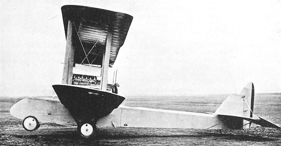
The unserialled Airco D.H.3 (2-120 h.p. Beardmore engines) which, despite attempts to mount the engines as far forward as possible, still rested on its tailskid when not occupied by its crew.
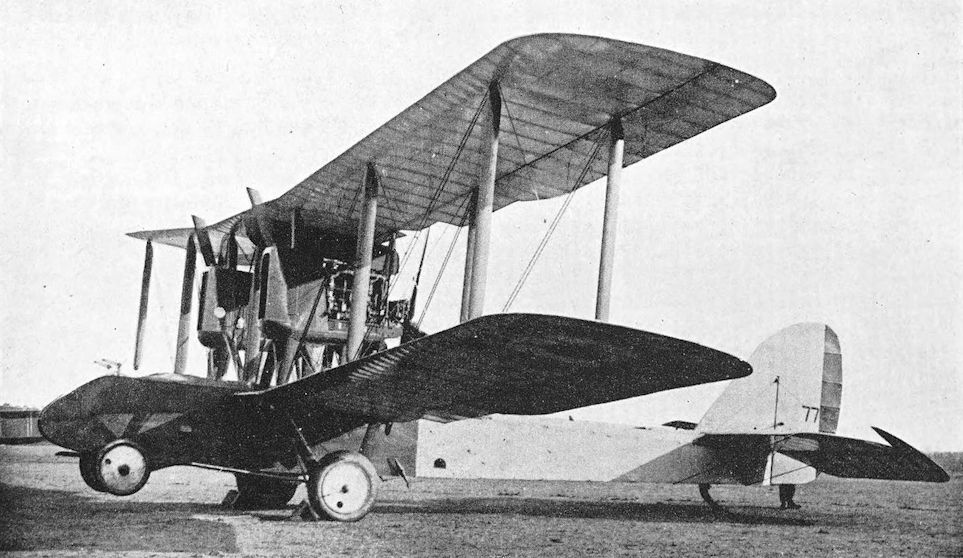
No 7744, the Airco D.H.3A, showing the cut back mainplane trailing edge, with 160hp Beardmore engines, whose increased weight more than cancelled the benefit of extra power and bestowed a slightly reduced performance compared with that of the D.H.3.
The three seat Airco DH 3 was to be the victim of an Air Board policy shift away from twin- to single-engined bombers. As a result, only one of the two prototypes ordered, serial no 7744, was completed and flown. Initially using two 120hp Beardmores, the machine proved somewhat underpowered and was re-engined to take the 160hp Beardmore as the DH 3a, the form in which it is seen here. First flown in April 1916, a contract for 50 production aircraft was cancelled in favour of the single-engined DH 4. Performance of the DH 3a included a top level speed of 95mph, a full military load of 680lb that included ammunition for the two .303-inch Lewis guns, along with a full load range of 700 miles. As it was, the experience gained with this machine was not totally wasted, the project being resurrected later in the form of the DH 10.
The three seat Airco DH 3 was to be the victim of an Air Board policy shift away from twin- to single-engined bombers. As a result, only one of the two prototypes ordered, serial no 7744, was completed and flown. Initially using two 120hp Beardmores, the machine proved somewhat underpowered and was re-engined to take the 160hp Beardmore as the DH 3a, the form in which it is seen here. First flown in April 1916, a contract for 50 production aircraft was cancelled in favour of the single-engined DH 4. Performance of the DH 3a included a top level speed of 95mph, a full military load of 680lb that included ammunition for the two .303-inch Lewis guns, along with a full load range of 700 miles. As it was, the experience gained with this machine was not totally wasted, the project being resurrected later in the form of the DH 10.
de Havilland 4
IN the D.H.4, Captain de Havilland produced one of the truly great aeroplanes of its day, one which had no peer among aircraft of its class in any of the combatant air forces, Allied or enemy. It was designed in response to an official request for an aeroplane to be used for day-bombing duties, and was the first British aircraft to be specifically designed for that purpose.
The power unit originally specified for the D.H.4 was the 160 h.p. Beardmore. That engine had been developed from the 120 h.p. Beardmore by F. B. Halford, and it was thanks to his skill that the 33 1/3 per cent increase in output was achieved. By the time when the D.H.4 design was being prepared, Halford had secured the cooperation of Sir William Beardmore and T. C. Pullinger in the design and manufacture of a new engine, the 230 h.p. B.H.P., or Beardmore-Halford-Pullinger.
The B.H.P. was similar to the Beardmore, for it was an upright six-cylinder in-line engine. It had, however, cylinders of cast aluminium monobloc construction with steel liners. In the adoption of this form of construction Halford had been inspired by the Hispano-Suiza engine, an example of which he had seen in France in 1915.
The first B.H.P. engine was running in June, 1916, and gave good results. After successfully completing its bench tests, it was installed in the prototype D.H.4 instead of the specified 160 h.p. Beardmore. It was a taller engine than the Beardmore, a fact which doubtless accounted for the “step” in the top line of the engine cowling of the aeroplane. With the B.H.P. engine the D.H.4 appeared at Hendon in August, 1916. Difficulties were encountered in the quantity production of this engine, however; in fact, the first production B.H.P.s did not appear until the middle of 1917.
Fortunately, an excellent alternative power unit was available: it was the 250 h.p. Rolls-Royce liquid-cooled vee-twelve engine which came to be known as the Eagle. This engine had originally been made for installation in seaplanes, but development and production had proceeded steadily from the time of the first bench test in May, 1915. The production Rolls-Royce engines had been coming off the lines since October, 1915, and by the end of 1916 sufficient quantities were available to enable the first production D.H.4s to be fitted with this type of engine.
Tests of the D.H.4 with both the B.H.P. and Rolls-Royce engines were highly successful, and the happy union with the latter motor enabled sufficient machines to be produced to equip No. 55 Squadron, R.F.C., before it went to France on March 6th, 1917. Later marks of the superb Eagle engine were fitted to the D.H.4 as development of the motor progressed; and with the Eagle VIII, which delivered 375 h.p., the aircraft had a better performance than most contemporary fighters.
The basic structural design of the D.H.4 was typical of its period. It was almost entirely made of wood, with wire cross-bracing and fabric covering. The fuselage was a conventional box-girder, but was made in two portions which were connected by fishplates immediately behind the observer’s cockpit; the forward portion was covered with plywood, which increased its strength considerably. The wings had two spruce spars, spindled out between the compression ribs, and the balance cables which interconnected the upper ailerons ran externally above the upper wing. The tailplane was also a wooden structure, and its incidence could be adjusted in flight by the pilot. The undercarriage was simple and strong: it consisted of two substantial wooden vees, to the apices of which the axle was bound by rubber cord.
As the power of the engine was successively increased, larger airscrews were fitted, and it was found that the original undercarriage did not give sufficient ground clearance. A taller undercarriage was therefore fitted and became standard on all later production D.H.4s, regardless of the type of engine installed in the machine.
The B.H.P.-powered prototype had its rear centre-section struts inclined forwards in side elevation; this arrangement did not appear in any production D.H.4s. There was a rather unsightly step-down in the top line of the engine cowling; the exhaust manifold terminated in a vertical stack which led the exhaust gases above the upper wing; and the engine drove a four-bladed airscrew.
The B.H.P. engine had to be modified in several ways to make it suitable for large-scale production. An unfortunate result of these modifications was that when the first batch of engines was delivered to the Aircraft Manufacturing Co. in July, 1917, it was found that they would not fit the D.H.4s: the engine mountings in the aircraft had been designed from early drawings of the B.H.P. engine. The airframes had to be returned to the shops for modification, and production was delayed. The machines which emerged had a much neater engine installation than the B.H.P.-powered prototype; some had stack exhausts, but quite a number had a simple horizontal manifold.
The various marks of Rolls-Royce Eagle had an exhaust manifold on each side of the engine: in many cases these manifolds were led up into twin stacks in front of the leading edge of the upper wing, but the stack extensions were not fitted to late production D.H.4s.
Other alternative power units which were fitted to production D.H.4s were the 200 h.p. R.A.F. 3a vee-twelve, the 260 h.p. Fiat, and, as a natural alternative to the B.H.P. engine, the 230 h.p. Siddeley Puma. The R.A.F. 3a installation was characterised by a single central exhaust stack, a radiator which tapered slightly from top to bottom, and a four-bladed left-hand airscrew. This version of the D.H.4 was used by Squadrons Nos. 18 and 49.
The installation of the Fiat engine made the nose of the D.H.4 resemble that of the later D.H.9; and this was the only production version of the machine which did not have a flat frontal radiator immediately behind the airscrew. The first installation was made in A.7532. The history of the Fiat-powered D.H.4s is of unusual interest. At the beginning of September, 1917, a hundred Russian pilots were receiving flying training in England, and fifty D.H.4s were under construction for the Russian Government. For these machines Russia had bought Fiat engines in Italy. At this time, however, the British War Cabinet decided to initiate a campaign of bombing raids on German towns in retaliation for the Gotha raids on London which had begun in September. In consequence of this decision it became imperative to augment the British bomber forces in France, and Russia was asked to forgo delivery of her fifty D.H.4s on the understanding that she would receive seventy-five in their place in the spring of 1918. Winter was approaching and operations on the Russian Front would be brought to a standstill by the weather, so the Russian Government agreed to the British request. On October 2nd, 1917, twenty of these D.H.4S were completed and crated for despatch to Russia, but as a result of the bargain they were diverted to the Western Front.
No Fiat-powered D.H.4s were used operationally by the 41st Wing (the forerunner of the Independent Force), but the diversion of the Russian D.H.4s to other duties on the Western Front released Rolls-Royce D.H.4s for the independent bombing operations.
A purely experimental engine installation in an early D.H.4 was that of a 300 h.p. Renault: this was probably made in France.
Early production D.H.4s had the observer’s Scarff ring-mounting immediately on top of the upper longerons and below the level of the fuselage top-decking. With the gun-ring at this level, the decking interfered with the free movement of the gun and was rather low for comfort. In later D.H.4s the gun-ring was raised to the level of the top of the decking, thereby increasing the effectiveness of the observer’s weapon. The decking aft of the rear cockpit was flat-topped in these later machines.
The early Westland-built D.H.4s supplied to the R.N.A.S. differed slightly from the standard machine. The Rolls-Royce Eagle was fitted, usually without radiator shutters, and in some machines the rocker-heads were cowled over. Twin Vickers guns were provided for the pilot in place of the customary single gun, and the observer’s gun-ring was built up to the top of the fuselage decking; the decking retained its rounded form right down to the tail, however. The weight of the additional Vickers gun and interrupter gear, and the drag of the externally mounted gun reduced the performance somewhat.
In the air, the D.H.4 handled well for a two-seater, and the Central Flying School reported on it in the following glowing terms:
“Stability. - Lateral very good; longitudinal very good; directional very good. Control. - Stick. Dual for elevator and rudder. Machine is exceptionally comfortable to fly and very easy to land. Exceptionally light on controls. Tail-adjusting gear enables pilot to fly or glide at any desired speed without effort.”
That report related to the prototype, but the D.H.4 retained its good handling characteristics throughout its development. A later report on the version with the Eagle VIII engine notes that the machine tended to be tail-heavy at full speed and nose-heavy with engine off, but that the manoeuvrability remained very good.
In performance the D.H.4 surpassed all contemporary aeroplanes in its class, and bettered most of the fighting scouts then in service. Its high ceiling particularly commended it to the bomber pilots of its day, and this desirable combination of speed, climb and tractability would at first glance seem to make the D.H.4 well-nigh invincible. More than once its speed and ceiling enabled it to escape from enemy fighters, but if it were intercepted and forced to fight it sometimes proved to be a comparatively easy victim. This vulnerability was attributed to the considerable distance which separated the pilot and observer.
The cockpits were arranged to give the pilot a good forward and downward view for bombing, and the observer a good field of fire for his Lewis gun. Thus the pilot’s cockpit was situated immediately under the centre-section, and the observer was several feet further aft; the main fuel tanks occupied the intervening space. This arrangement succeeded in its original object, but the distance between the cockpits prevented that close and immediate cooperation between pilot and observer which was so essential in combat. The speaking-tube which connected the cockpits was of little practical use, and the fighting efficiency of the aeroplane suffered considerably from the separation of its crew. The observer had full dual control, with duplicated altimeter and air-speed indicator; his control column was detachable.
No. 55 Squadron, R.F.C., took the first D.H.4s to France on March 6th, 1917, and from that day until the Armistice twenty months later the machine served with the R.F.C., R.N.A.S. and R.A.F. as a day-bomber, fighter-reconnaissance, photographic, anti-Zeppelin and anti-submarine aeroplane. No. 55 Squadron arrived in time to take part in the Battle of Arras, and made their first operational sortie on April 6th, 1917, when six D.H.4s attacked Valenciennes railway station. Valenciennes was attacked several times by the squadron, and on May 3rd the D.H.4s bombed the railway junctions at Busigny and Brebieres. Machines of this unit also carried out long-range photographic reconnaissances: these missions were flown by single D.H.4S at heights between 16,000 and 21,000 feet.
No. 57 Squadron began to re-equip with D.H.4s in May, 1917, and was able to participate in the Battle of Ypres in company with No. 55 Squadron. In June, 1917, No. 18 Squadron was re-equipped with D.H.4s; No. 25 followed suit in July; No. 49 Squadron arrived in France on November 12th equipped with the type; and in the same month No. 27 Squadron began to replace their Martinsyde Elephants with D.H.4s. The four last-named squadrons were in action during the Battle of Cambrai, and in the period preceding the great German offensive of March, 1918, the D.H.4s of Nos. 25 and 49 Squadrons were employed on photographic reconnaissance.
During the offensive itself, the D.H.4s of No. 5 (Naval) Squadron joined the day-bomber force, and all units were actively employed against the advancing enemy forces. Until March 25th, four days after the beginning of the enemy offensive, the D.H.4s had bombed from heights of 14,000 to 16,000 feet, and the effect of their bombs had been more moral than destructive. This height was adhered to because of an order issued in August, 1917, when D.H.4s were scarce, which stated that the type was not to be used below 15,000 feet. By March 25th, 1918, the situation had become so critical that Major-General J. M. Salmond had ordered the squadrons of the 9th Wing to make low-flying attacks; all risks were to be taken. This order concerned Squadrons Nos. 25 and 27, and on the following day No. 5 (Naval) Squadron was placed under similar orders. Despite unfavourable weather, these units carried out their orders to the letter, and played a leading part in harassing enemy troops. Low-flying attacks were also made by Nos. 18 and 49 Squadrons, but by March 31st the D.H.4s were able to resume bombing from more comfortable altitudes.
When the German forces were beaten back throughout the summer and autumn of 1918, the D.H.4s again gave of their best. They acquitted themselves with more distinction than the D.H.9s, which were then coming into service and were replacing the D.H.4 in several squadrons. No. 205 Squadron, R.A.F. (as No. 5 Naval had become on April 1st, 1918), distinguished itself in repeated attacks on strategic bridges, and during four days in August, 1918, the D.H.4s of this unit flew for 324 hours 13 minutes and dropped a total of 16 tons of bombs.
At the beginning of October, 1917, No. 55 Squadron had been withdrawn from the British front, and became one of the three units composing the 41st Wing: the two others were No. too (F.E.2b) Squadron and No. 16 (Naval) Squadron, which had Handley Page O/100s. These squadrons formed the nucleus of what was successively named the VIII Brigade and, on June 6th, 1918, the Independent Force, R.A.F. From their base at Ochey they carried out the first organised programme of strategic bombing.
On October 17 th, 1917, eight of the D.H.4s of No. 55 Squadron made their first raid after joining the 41st Wing. The objective was Saarbrucken, which was revisited many times by No. 55 in the course of the ninety-four further sorties made by the squadron before the Armistice. Other towns in which the D.H.4s made the lot of the munition workers an unhappy one were Mannheim, Metz-Sablon, Kaiserslautern, and Frankfurt. Raids on Frankfurt, Duren and Darmstadt extended the D.H.4s to the limit of their maximum endurance of five and a half hours, and there was no safety margin for combat. In Cologne, a minor panic followed an attack by six D.H.4s on May 18th, 1918, for the town had been attacked only twice before. That was not the only occasion on which No. 55 Squadron bombed Cologne, however.
These operations cost No. 55 Squadron sixty-nine D.H.4s. Eighteen were missing and fifty-one wrecked.
The R.N.A.S. began to receive D.H.4s in the spring of 1917, and the first overseas unit to receive the type was No. 2 (Naval) Squadron at St Pol, followed by No. 5 (Naval): the latter unit had completely replaced its Sopwith 1 1/2-Strutters by the middle of August, 1917. In addition to day-bombing attacks, these R.N.A.S. D.H.4s did much useful coastal patrol work. The D.H.4s of No. 202 Squadron spent weeks in taking photographs of the whole area and defence system around Zeebrugge before the naval attack of April 22nd/23rd, 1918.
For anti-submarine patrol, No. 17 (Naval) Squadron was formed with D.H.4s on January 13th, 1918; and 1918 saw the former Naval fighting squadrons Nos. 6 and 11 revived and initially equipped with D.H.4s. The submarine U.B.12 was sunk on August 12th, 1918, by four D.H.4s of No. 217 (formerly No. 17 Naval) Squadron. Captain K. G. Boyd scored direct hits with his two 230-lb bombs.
R.N.A.S. units in England received D.H.4s for anti-Zeppelin patrols. Great Yarmouth air station received its first D.H.4 in August, 1917, and welcomed it as an overdue replacement for the B.E.2c’s which had been the unit’s best night-flying aeroplane up to that time. On August 26th two D.H.4s of unusual interest arrived at Great Yarmouth. These were special long-range machines, powered by the R.A.F. 3a engine and fitted with tanks which would give them an endurance of about fourteen hours.
The long-range D.H.4s had been specially modified to make a photographic reconnaissance of the Kiel Canal. The take-off was to have been made from Bacton, whence the machines were to fly across the North Sea, take their photographs, and land at Dunkerque. These D.H.4s were specially camouflaged with matt dope of fawn and blue. They were flown to Bacton on August 9th, 1917, but a few days later the Admiralty decided not to proceed with the plan, and the D.H.4s were sent to Great Yarmouth for anti-Zeppelin duties.
On September 5th, 1917, one of the Great Yarmouth D.H.4s collaborated with the Curtiss H.12 flying-boat No. 8666 in attacking the Zeppelin L.44. The airship escaped, but the D.H.4 developed engine trouble and had to ditch. The port engine of the flying-boat was not running well, but Flight-Lieutenant R. Leckie went down at once and rescued Flight-Lieutenant A. H. H. Gilligan and Lieutenant G. S. Trewin from the wreckage of their D.H.4. This early attempt at air-sea rescue nearly ended in disaster, for the flying-boat was unable to take off again. Leckie taxied towards England until his fuel ran out, and the six men were not picked up until September 7th when they were sighted by H.M.S. Halcyon.
These R.N.A.S. D.H.4s had no flotation gear of any kind, but experiments with the Grain Flotation Gear were carried out at the Marine Experimental Aircraft Depot, Isle of Grain. D.H.4s with Siddeley Puma and R.A.F.3a engines were used; one of the Puma-Fours was tested with flotation gear in January, 1918. Tests were also carried out with D.H.4s which had a biplane hydrovane mounted ahead of the undercarriage: the wheels were jettisoned by means of compressed air before alighting. Inflatable canvas bags were attached to the lower longerons and small stabilising floats were fitted under the lower wingtips.
A twin-float version of the D.H.4 existed, and may have been an attempt to provide a patrol seaplane with a worthwhile performance. The D.H.4 seaplane had a Rolls-Royce Eagle engine, and its floats resembled those of the Wight seaplanes; there was no tail float.
A D.H.4 from Great Yarmouth shot down the Zeppelin L.70 on August 5th, 1918. On board the airship was Fregattenkapitan Peter Strasser, the Commander-in-Chief of the Imperial German Naval Airship Service, and his death was a severe blow to the enemy. The D.H.4, A.8032, was flown by Major Egbert Cadbury, and his gunner was Captain Robert Leckie, D.S.O., D.S.C. Cadbury attacked the airship from ahead and slightly to port at a height of 16,400 feet about forty miles north-east of Yarmouth. Leckie’s Lewis gun was loaded with Z.P.T. ammunition which instantly set fire to the Zeppelin, and Cadbury later estimated that the whole ship was consumed by the flames in about three-quarters of a minute. Cadbury then turned on the L.65, which was accompanying the L.70, but Leckie’s gun jammed and the airship escaped.
At the time, it could not be known that the night of the L.yo’s end marked the last of the Zeppelin raids on the United Kingdom, and work continued on various means of overcoming the Zeppelin menace. It was thought that the Coventry Ordnance Works 1 1/2-pounder quick-firing gun would be an effective weapon for anti-airship work, and two D.H.4s were specially modified to carry a gun of this type: one of these machines was A.2168. In these D.H.4s the gun was fixed to point upwards at an acute angle; the breech was close to the floor of the rear cockpit, and the muzzle protruded through the upper centresection, which had to be covered with sheet metal to withstand the blast. The gun was aimed in a fashion similar to that adopted on Home Defence Bristol Fighters. The pilot had a sight mounted parallel to the C.O.W. gun, and this he aligned with the target by careful use of the. elevators, whereupon he gave the gunner the signal to fire.
The airframes of the D.H.4s had to be extensively strengthened to withstand the recoil of the gun; consequently they were overloaded and rather unpleasant to fly. An added discomfort for the pilot was the firing of the gun immediately behind his head.
By the time the C.O.W.-gun D.H.4s were ready, Zeppelin raids on the United Kingdom had ceased. A night test over the enemy lines was ordered, but the Armistice was signed a few days after the machines arrived in France, and they saw no operational service.
The D.H.4 was used in experiments with the provision of parachutes for aircrew. A Puma-powered D.H.4 was tested with two Guardian Angel parachutes in November, 1918.
Further experimental engine installations were tested in 1918. One was the 400 h.p. Sunbeam Matabele, which was flown in the D.H.4 numbered A.8083. The engine was a vee-twelve with cylinders of the same bore and stroke as those of the Sunbeam Saracen, an earlier six-cylinder in-line engine.
Of much greater significance was the installation in a D.H.4 of the experimental Ricardo-Halford Inverted Supercharger engine. F. B. Halford first met H. R. (later Sir Harry) Ricardo early in 1916, and soon became his enthusiastic disciple and collaborator. Ricardo did a prodigious amount of inspired work in the design of aircraft engines and the development of their fuels, but his pioneering efforts have received comparatively little recognition.
In 1918 Ricardo and Halford, working independently of the Royal Aircraft Factory’s experiments with supercharged engines, collaborated in the design of the Ricardo Supercharger, one of the first engines to be designed from the start as a supercharged power unit. When it was completed, the engine was unusually tall, and it would have been difficult to devise an installation which did not block the pilot’s view. Halford conceived the idea of inverting the engine, and did much of the design work connected with the necessary modifications. The Ricardo-Halford Inverted Supercharger was installed in a D.H.4 and was successfully flown at Farnborough.
The first D.H.4s to reach Mesopotamia were two which were allotted to No. 30 Squadron. Neither survived for long: one received a direct hit by an anti-aircraft shell and blew up in the air on January 21 st, 1918, and the second caught fire at 1,000 feet during a raid on Kifri on the night of January 25th/26th. The latter machine landed in time to enable its crew to escape.
Later, a few D.H.4s were on the strength of “A” Flight of No. 72 Squadron, which had arrived at Basra on March 2nd.
The R.N.A.S. units on the Aegean Islands of Imbros, Lemnos, Mitylene and Thasos used D.H.4s. The unit known as “C” Squadron moved to a new aerodrome at Gliki, on Imbros, in October, 1917; and during the following month the two D.H.4s which had been sent to reinforce the squadron began a series of attacks on the main Sofia-Constantinople railway.
On January 20th, 1918, the D.H.4s of the R.N.A.S. began a sustained attack on the German cruiser Goeben when she had run aground in the Narrows after coming out of the Dardanelles. The attacks continued by day and night until January 24th, but no hits were scored, and the Goeben returned to Constantinople on the 27th. A watch was kept on her as she lay at her moorings in Stenia Bay by D.H.4s specially fitted with long-range tanks to ensure an endurance of seven hours.
One of the D.H.4s from Mudros went to the aerodrome at Amberkoj on September 24th, 1918, to assist No. 17 Squadron in its attacks on the retreating Bulgars.
The Italian-based D.H.4s of the 66th and 67th Wings made several attacks on the enemy submarine bases at Cattaro and Durazzo. Attacks on Cattaro entailed a flight of 400 miles over the sea.
Among the machines which went to northern Russia with the R.A.F. contingent in May, 1918, were eight D.H.4s with R.A.F. 3a engines: these operated with a special force which was sent to Archangel. Later in the campaign some Fiat-powered D.H.4s joined the R.A.F. contingent. After the Armistice was signed, the R.A.F. remained on active service in Russia, and another unit was set up at Baku in January, 1919, to support British naval forces in the Caspian Sea. The equipment of this unit included D.H.4s which carried out bombing raids on Astrakhan and other ports until October, 1919, when the R.A.F. unit was recalled. At least one D.H.4 was used by the Red aviation service after it had been captured intact.
Of all the British aeroplanes which were selected for production in America, only the D.H.4 was produced in substantial numbers. It was the only American-built British type to see operational service in France.
Even before the Liberty engine was designed, the original procurement programme of 7,375 aeroplanes presented to the Secretaries of the War and Navy Departments on May 25th, 1917, included 1,700 D.H.4s. The fact that the D.H.4 was obviously capable of using the American-designed Liberty 12 engine made it highly desirable in American eyes.
The first D.H.4 to be flown in America was a British-built machine which had been delivered, without engine, to Dayton, Ohio, on August 15th, 1917. Ten days later the first Liberty 12 successfully completed a fifty-hour bench run, and was rated at 314 h.p. By October, 1917, the power output had been raised to 395 h.p., and on the 29th of that month the engine was flown in the D.H.4 for tbe first time.
Contracts for the production of the D.H.4 were placed with the Dayton-Wright, Fisher Body and Standard concerns, from whom a total of 9,500 machines were ordered; and by the time of the Armistice these manufacturers had produced a total of 3,227 Liberty-powered D.H.4s. The first production aircraft were delivered by Dayton-Wright in February, 1918. Before the end of the war, 1,885 American-built D.H.4s were despatched to France for the use of the American Expeditionary Force, and the type was used operationally by twelve squadrons. The first American-built D.H.4 joined the A.E.F. on May 11 th, 1918.
Development proceeded in America, and in July, 1918, the Engineering Division of the Bureau of Aircraft Production installed a revised fuel system in a D.H.4, which was thereupon re-designated D.H.4A (but should not be confused with the British post-war commercial D.H.4A). The second modification of the D.H.4, made in October, 1918, by the Engineering Division, was the D.H.4B. This was the D.H.4A with the positions of the pilot and fuel tanks interchanged.
American production ceased with the Armistice, when seven contracts for a total of 7,502 D.H.4s were cancelled; but during the period 1919-23 many hundreds of D.H.4s were converted to D.H.4Bs: 1,538 were modified by ten different contractors from February, 1919, onwards, and many others were similarly converted by air depots. The type survived for many years in America, and scores of variants of the basic design appeared over the years. In 1923-24, some 285 D.H.4s and D.H.4Bs were given steel tube fuselages by the Atlantic and Boeing concerns: these machines were re-designated D.H.4M, D.H.4M-1 and D.H.4M-2. Numbers of surplus D.H.4s were taken over by the Post Office Department in 1919, and were modified to carry air-mail: in this capacity the type served until 1927. This version of the D.H.4 was not particularly pleasant to fly and was not popular with its pilots. The first twelve machines converted by the L.W.F. Engineering Co. were fitted with a rain-proof compartment for 500 lb of mails in what was originally the front cockpit. The machine was flown from the rear seat, and a steel tube undercarriage was fitted.
At home, the post-war use of the D.H.4 was almost wholly commercial in character, beginning with its use by the R.A.F. Communications Wing during the 1919 Peace Conference, when a London-to-Paris service was operated. In that year a cabin version, designated D.H.4A, appeared: there was accommodation for two passengers. Another post-war version was the drastically modified D.H.4R racer with clipped lower wings and a 450 h.p. Napier Lion engine. The D.H.4R won the 1919 Aerial Derby, and was capable of 150 m.p.h.
In July, 1919, a D.H.4 was used to test an experimental Rolls-Royce engine known as the Experimental G. This power unit gave 353 h.p. at 1,800 r.p.m.
After the end of the war, D.H.4s were sold to Greece and Spain, and individual machines went as far afield as Japan, New Guinea and Australia. In Canada, the type was used as a forestry patrol aircraft for several years.
SPECIFICATION
Manufacturers: The Aircraft Manufacturing Co., Ltd., Hendon, London, N.W.
Other Contractors: F. W. Berwick & Co., Ltd., Park Royal, London, N.W.10. Westland Aircraft Works, Yeovil, Somerset. Vulcan Motor and Engineering Co. (1906), Ltd., Crossens, Southport.
American Contractors: The Dayton-Wright Airplane Co., Dayton, Ohio; The Fisher Body Corporation; Standard Aircraft Corporation, Elizabeth, New Jersey.
For conversions to D.H.4B: The Aeromarine Plane and Motor Co., Keyport, New Jersey; Gallaudet Aircraft Corporation, East Greenwich, Connecticut; The L.W.F. Engineering Co., College Point, New York; Thomas-Morse Aircraft Corporation, Ithaca, New York.
Power: 230 h.p. P.H.P. (both Galloway and Siddeley-made); 230 h.p. Siddeley Puma; 250 h.p. Rolls-Royce Mk. Ill (Eagle III); 275 h.p. Rolls-Royce Mk. II (322 h.p. Eagle VI); 275 h.p. Rolls-Royce Mk. Ill (325 h.p. Eagle VII); 375 h.p. Rolls-Royce Eagle VIII; 353 h.p. Rolls-Royce Experimental G engine; 200 h.p. R.A.F. 3a; 400 h.p. Sunbeam Matabele; 260 h.p. Fiat; 300 h.p. Renault; 400 h.p. Liberty 12; Ricardo-Halford Inverted Supercharger.
Dimensions: Span: 42 ft 4 5/8 in. (American-built D.H.4: 42 ft 5 3/4 in.). Length: 29 ft 8 in. with R.A.F. 3a and Fiat engines, 30 ft 8 in. with Rolls-Royce and Puma engines, 30 ft 5 61/64 in. with Liberty. Height: 10 ft 1 in. with B.H.P., Puma and Rolls-Royce G engines; 10 ft 3 20/32 in. with Liberty; 10 ft 5 in. with R.A.F. 3a, Eagle III and Fiat engines; 11 ft with Eagle VIII engine. Chord: 5 ft 6 in. Gap: 5 ft 6 in. Stagger: 12 in. Dihedral: 30. Incidence: 30. Span of tail: 14 ft (American-built D.H.4: 13 ft 7 in.). Wheel track: 6 ft. Airscrew diameter: B.H.P. and Eagle III, 8 ft 9 in.; Fiat, 8 ft 11 in.; R.A.F. 3a, 10 ft; Eagle VIII, 10 ft 2 in.
Areas: Wings: upper 223 sq ft, lower 211 sq ft, total 434 sq ft. Ailerons: each 20-5 sq ft, total 82 sq ft. Tailplane: 38 sq ft. Elevators: 24 sq ft. Fin: 5-4 sq ft. Rudder: 13-7 sq ft.
Tankage (in gallons):
Petrol Oil Water
230 h.p. B.H.P. 62 1/2 5 1/2 6
250 h.p. Rolls-Royce 65 4 1/2 -
Rolls-Royce Eagle VIII 65 3/4 5 1/2 9
R.A.F. 3a 65 1/2 4 1/2 -
Fiat 65 5 8
Liberty 88 - -
Armament: Standard armament consisted of one fixed forward-firing Vickers machine-gun mounted on top of the fuselage to port of centre and synchronised by Constantinesco gear; the observer had either a single Lewis gun or a double-yoked pair on the Scarff ring-mounting on the rear cockpit. The Westland-built D.H.4s for the R.N.A.S., some of which were diverted to the R.F.C., had twin Vickers guns for the pilot, and some R.N.A.S. machines had Lewis guns on separate pillar-type mountings in the rear cockpit instead of the Scarff mounting. American-built D.H.4s had two fixed Marlin machine-guns and twin Lewis guns for the observer. Bomb racks were fitted under the fuselage and each lower wing: the bomb load consisted of two 230-lb, four 112-lb bombs, or their equivalent. Depth charges could be carried instead of bombs.
British Production and Allocation: Production of D.H.4s totalled 1,449. Of these, 1,170 were delivered to the R.F.C. and R.A.F.; presumably the remainder went to the R.N.A.S. and into store. 664 went to the Expeditionary Force in France; ninety-one to the Independent Force; eighteen to the Middle East Brigade; one to the Mediterranean in 1918; sixty-seven to the 5th Group in 1918 for anti-submarine patrol (Squadrons Nos. 202 and 217); one to a Home Defence unit in 1917; and 328 to training units.
On October 31st, 1918, the R.A.F. had on charge 548 D.H.4s; 373 with Rolls-Royce engines, seventy-two with R.A.F. 3a, ninety-eight with B.H.P., and five with Fiat. These were distributed as follows:
Rolls-Royce R.A.F. 3a B.H.P. Fiat
With E.F. in France 120 25 12 1
Independent Force 70 - - 2
5th Group 37 - - -
In transit to Middle East - 4 - -
Mesopotamia - 9 - -
Mediterranean 2 4 20 -
Attached to Grand Fleet 4 - - -
11th (Irish) Group - 3 3 -
Training units - - 17 -
Sundry home units 27 17 44 2
Aeroplane Repair Depots 75 6 1 -
With contractors 15 4 1 -
In store 23 - - -
Totals 373 72 98 5
Service Use: Western Front: R.F.C. Squadrons Nos. 18, 25, 27, 49, 55 and 57; R.N.A.S. Squadrons Nos. 5, 6 and 11 (later Nos. 205, 206 and 211, R.A.F.); American units, 8th, nth, 20th, 50th, 85th, 100th, 135th, 155th, 166th, 168th, 278th and 354th Aero Squadrons. The 96th Aero Squadron had a few D.H.4S. Some were used by the U.S. Naval Northern Bombing Group. Coastal Patrol: R.N.A.S. Squadrons Nos. 2, 5 and 17 (later Nos. 202, 205 and 217, R.A.F.), No. 212 (part only), No. 273 (part only), R.N.A.S. Stations Port Victoria and Redcar. Home Defence: R.N.A.S. Great Yarmouth (later No. 212 Squadron, R.A.F.). Mesopotamia: No. 30 Squadron had two D.H.4s; No. 72 Squadron, “A” Flight. Macedonia: one D.H.4 from Mudros (probably No. 223 Squadron) attached to No. 17 Squadron. Aegean: “C” Squadron, Imbros. “D” Squadron, Stavros. R.N.A.S. Station, Mudros. 62nd and 63rd Wings (Squadrons Nos. 220, 221, 222 and 223). Adriatic: 66th and 67th Wings (Squadrons Nos. 224, 225, 226 and 227). Russia: R.A.F. contingent at Archangel (May, 1918) had eight D.H.4s with R.A.F. 3a engines. Fiat-powered D.H.4s were later used in northern Russia. Training: No. 51 Squadron. Air Observers’ Schools at Mansion, New Romney and Eastchurch. School of Photography, Maps and Reconnaissance, Farnborough. Schools of Navigation and Bomb-dropping, Andover, Stonehenge and Thetford. Aerial Fighting Schools at Turnberry, Marske and Sedgeford. No. 10 Training Depot Squadron, Harling Road. No. 31 Training Squadron, Wyton. American version used at Ford junction, Sussex.
Serial Numbers:
Serial No. Contractor Contract No.
3696 Aircraft Manufacturing Co.
A.2125-A.2174
A.7401-A.8089 Aircraft Manufacturing Co. 87/A/496
B.1482
B.2051-B.2150 F. W. Berwick & Co., Ltd.
B.3957-B.3960 Westland-built R.N.A.S.-type D.H.4s, probably renumbered from N series
B.5451-B.5550 Vulcan Motor Co.
B.9476-B.9500 Westland Aircraft A.S.29679
C.4501-C.4540 Aircraft Manufacturing Co. A.S.24960
D.1751-D.1775 Westland Aircraft A.S.29679
D.8351-D.8430 Aircraft Manufacturing Co. A.S.37726
D.923I-D.9280 Aircraft Manufacturing Co.
Between, and about
F.2635-F.2704 -
Between and about
F.5715-F.5828 -
About F.7597 -
N.5960-N.6009 Allotted for D.H.4s to be built by Westland Aircraft, but only the following were delivered: N.5960-N.5990, N.5992, N.5996, N.5997, N.6000, N.6001, N.6004, N.6005, N.6007, N.6009.*
N.6380-N.6399 Allotted for D.H.4s, but N.6393 and N.6397 were not delivered with N. serials.*
N.6400-N.6429 Westland Aircraft
* The missing D.H.4s in these batches may have been delivered to the R.F.C. and renumbered; e.g. B.3957.
Notes on Individual Machines: Used by No. 5 (Naval) Squadron, later No. 205 Squadron, R.A.F.: A.7518, A.7573, A.7620, A.7644, A.7664, A.7739, A.7742, A.7811, A.7908, A.7939, A.7964, A.8071, A.8084, D.9232, D.9238, D.9241, D.9243, N.5962, N.5967, N.5968, N.5971, N.5974, N.5977, N.5978, N.5982, N.5996, N.6000, N.6001, N.6004, N.6005, N.6008, N.6009. Used by No. 17 (Naval) Squadron, later No. 217 Squadron, R.A.F.: A.7772, A.7773, A.7846, A.7863, A.7867, A.7870, A.7875, A.7925, A.7935, A.7964, A.8013, A.8022, A.8050, A.8056, A.8059, A.8067, A.8072, D.8353, D.8366, D.8370, D.8393. Used at R.N.A.S. Station, Mudros: N.6410, N.6411, N.6420. Used by “C” Squadron, R.N.A.S., Gliki, Imbros: N.5975, N.5976. Used by No. 18 Squadron, R.F.C.: A.7550 (R.A.F. 3a engine), A.7594, A.7614, A.7653, A.7815, A.7907, A.8000, A.8041. Used by No. 25 Squadron: A.7442 (“B”), A.7477, A.7479, A.7482, A.7486, 7489, A.7505. Used by No. 27 Squadron: A.7677, B.2077. Used by No. 51 Squadron: A.2134, A.2138, 3960. Used by No. 55 Squadron: A.2130, A.2144, A.2145, A.2150, A.2159, A.2161, A.7418, A.7421, A.7469, A.7791. Used by No. 57 Squadron: A.2138, A.2174, A.7424, A.7492, A.7510, A.7554, A.7555, A.7563, A.7564, A.7568, A.7904, D.8419, D.8425, D.9262, F.2635, F.5828. Used at No. 1 School of Navigation and Bomb-dropping, Stonehenge: A.2136, A.7871, B.5483. Other machines: A.7483, “Australia No. 5, N.S.W. No. 4. The F. J. White, Saumarez and Baldblair”. A.7488, “Australia No. 18, N.S.W. No. 17, Government”. A.7559, became prototype D.H.9. A.7864, “Felixstowe”, R.A.F. 3a engine. A.8083, experimental installation of Sunbeam Matabele engine. D.8380, “The Women of Malaya, Malaya No. 27”. N.5984: “D” Squadron, R.N.A.S., Stavros. N.5985: No. 2 (Naval) Squadron. N.6404, R.N.A.S. Port Victoria; 230 h.p. B.H.P. engine.
Costs:
D.H.4 airframe (for R.A.F. 3a engine) without engine, instruments and armament £1424 10s.
R.A.F. 3a engine £1,210 0s.
American Production and Deliveries:
Contracts:
Contractor Order No. Quantity ordered Number delivered Notes
Dayton-Wright 20038-A 4,000 3,098
20038-4 7 7 Remodelling order
20038-44 1,000 None
20529-1 6 6
Fisher Body 20207-A 4,000 1,600
Standard 20516 500 None Order cancelled
20516-A 500 140
As at November 11th, 1918:
Total U.S. production 3,227
Despatched by sea 1,885
Received overseas (unassembled) 1,185 in France
Assembled overseas 1,025
Put into service 984
In service at the Front 628
In commission at the Front 457

The prototype D.H.4 with B.H.P. engine, serial number 3696, at Hendon in August 1916 showing the forward-sloping rear centre-section struts.

A D.H.4 with 230hp BHP, the engine intended for the first production aircraft but which did not materialise until mid-1917; note the engine's characteristic oval-shaped radiator and the lengthened undercarriage, introduced since the early production aircraft.

Art early Airco-built D.H.4, A2152, with 250hp Rolls-Royce Eagle III engine, during assessment trials at the Royal Aircraft Factory, Farnborough. Note the considerable distance between the cockpits, one of the few features which drew criticism from the RFC.

Eagle-powered D.H.4 with taller undercarriage.

Westland-built D.H.4 for R.N.A.S. This version had twin Vickers guns for the pilot, and the observer’s gun-ring was raised. The engine was a Rolls-Royce Eagle.

D.H.4 A2148 with experimental 300 h.p. Renault 12Fe engine.

D.H.4 with R.A.F. 3a engine.

The 1 1/2-pounder C.O.W. quick firing anti-Zeppelin gun mounted in D.H.4 A2168. The engine is a R.A.F. 3a with modified exhaust arrangements. Long exhaust pipes replaced the short stacks of the standard aircraft.

A Fiat-powered D.H.4 with bomb rack under the fuselage possibly intended for a single 230 lb bomb. Although the engine cowling contours appeared better than other D.H.4 installations, the overall effect was considerably greater drag owing to the exposed cylinders and the mounting of the radiator under the nose.

The Sopwith B.I with D.H.4s of the R.N.A.S. Fifth Wing at Coudekerque.

A coastal patrol D.H.4 with twin float undercarriage.

The D.H.4, A.7457, with hydrovane fitted to the undercarriage and stowed flotation gear. The engine is a R.A.F. 3a.

Westland-built D.H.4, D.1769, with hydrovane on the undercarriage and fittings for flotation gear. The engine is a Siddeley Puma.

American-built D.H.4 with Liberty 12 engine.
de Havilland 5
THE D.H.5 was designed in 1916, when D.H.2 and F.E.8 pusher scouts were still in service. By that time, however, several British synchronising gears for machine-guns had become available to designers, and the way was clear for the combination of forward-firing armament and the superior performance of the tractor aeroplane. The last great asset of the pusher layout was the excellent forward view from the cockpit, and the peculiar design of the D.H.5 was the result of attempting to provide a tractor aeroplane with the uninterrupted forward outlook of the pusher.
The manner of achievement of this compromise was unconventional. The mainplanes were rigged with a pronounced backwards stagger of 27 inches, and the pilot sat below and in front of the leading edge of the upper wing. Otherwise the machine’s structure was fairly typical of its time. The fuselage was basically a wooden box-girder with wire cross-bracing, and in the prototype D.H.5 was flat-sided with a rounded top-decking and fairings behind the engine cowling on either side. The same basic structure remained in production machines, but the fairing of the engine cowling was carried smoothly into the lines of the fuselage which, aft of the centre-section struts, was of octagonal cross-section. The fuselage was made in two parts joined at the line of the rear centre-section struts. The forward portion embodied plywood reinforcing-webs, and the rear portion was wire-braced throughout with plywood webs applied to the two rear bays. The main fuel tank was immediately behind the pilot, and the oil tank was directly above it. There was an external gravity fuel tank of 5-gallon capacity on the starboard upper wing. The undercarriage was a plain vee structure with two steel tube spreader bars and rubber cord shock absorbers.
The mainplanes had two wooden spars, spindled out for lightness, connected by steel tube compression struts and cross-braced by steel wire. Single-bay interplane bracing was used, and both landing and flying wires were single. The tail-unit was of wooden construction, with steel tube forward edges on rudder and elevators. The rudder of the prototype was horn-balanced; but a plain rudder was fitted to production D.H.5s, and the size of the vertical tail surfaces was slightly increased. The standard engine was the 110 h.p. Le Rhone, but there are indications that an experimental installation of the 110 h.p. Clerget may have been made.
The production machines began to appear in the spring of 1917, and the D.H.5s made their debut in France in May of that year. No. 24 Squadron received its first D.H.5 on May 1st, and No. 32 Squadron began to re-equip with the type at about the same time. Both units had been flying D.H.2s, and still had one or two of their faithful little pushers on June 7th. The F.E.8s of No. 41 Squadron were replaced by D.H.5s in July, 1917; No. 68 (Australian) Squadron went to France with D.H.5s on September 21st; and No. 64 followed, similarly equipped, on October 15th.
In 1917, an aeroplane with the radical appearance of the D.H.5 could not fail to give rise to a host of extraordinary rumours. In the case of the D.H.5 these centred around its stalling characteristics. It must be admitted that the machine’s behaviour at the stall was not all it might have been, and much play was made with the theory that the lower wing blanketed the upper by virtue of their relative positions and thereby made recovery difficult. There was, however, no foundation for the rumour that the D.H.5 stalled at 80 m.p.h., viciously and without warning.
One pilot has recorded that, when he was ordered to take a D.H.5 on a delivery flight, he was warned not to try to fly it at less than 90 m.p.h. Soon after take-off he found himself in difficulties owing to engine trouble, but he was relieved to find that the machine’s stalling characteristics had been greatly exaggerated, and that it was “a most comfortable and pleasant machine to fly, extremely sensitive to aileron control.” The D.H.5’s ailerons were large and of high aspect-ratio.
The machine was highly manoeuvrable and capable of all the normal aerobatics, but it never achieved popularity. A number of accidents which occurred with D.H.5s at training aerodromes did little to make it more popular, and several of these were attributed to a tendency for elevator control to diminish dangerously near the stall.
The first D.H.5 to go to France did so late in 1916, presumably for Service trials; but the type did not begin to be operational until the end of May, 1917. On the 25th of that month, Second Lieutenant S. Cockerell of No. 24 Squadron scored the first victory by a D.H.5 of his squadron. Combat successes did not come easily to the D.H.5, and in 205 combats between May 25th and December 25th, 1917, No. 24 Squadron could claim only three enemy machines as completely destroyed, whereas in the 774 combats fought by the squadron when equipped with the D.H.2 no fewer than forty-four enemy machines were destroyed.
The D.H.5 was not at its best above 10,000 feet, and it was found that when, as in November, 1917, it was necessary to send out mixed formations, these had to be arranged in layers with the D.H.5s at the lowest level. A typical arrangement was for Sopwith Pups to be at 15,000 feet, Bristol Fighters at 12,000 feet, and D.H.5S at 9,000 feet; and the fact that the D.H.5 was inferior to the earlier Pup in ability to hold its height in combat did not improve its reputation with its pilots.
It is as a ground-attack aeroplane that the D.H.5's best remembered. It was peculiarly well suited to this hazardous duty, for it was strong and from its cockpit the pilot had an unusually good forward view. The first organised use of D.H.5s for ground-strafing occurred during the Battles of Ypres. On August 16th, 1917, two D.H.5s were allotted to each divisional front for cooperation with the forward infantry. One week earlier, the D.H.5s of No. 41 Squadron had demonstrated the use of the type on ground-attack work when they greatly assisted an infantry assault opposite Boiry Notre Dame by attacking enemy trenches, machine-gun emplacements, and trench-mortar positions.
The Battle of Cambrai again saw the D.H.5 used on ground-strafing duties. These were so much accepted as part of the D.H.s’s normal work that No. 64 Squadron had practised much low-flying before going overseas, and after the arrival of the unit in France low-flying in formation was practised. By this time (November, 1917), the D.H.5s were carrying four 25-lb bombs, and No. 64 Squadron and No. 68 (Australian) Squadron did a considerable amount of low-level bombing and strafing during the battle.
Cambrai virtually marked the end of the D.H.5s operational career, for all the squadrons using the type were re-equipped with S.E.5a’s by the end of January, 1918. Its Service life was brief, even by the standards of the First World War, and it did not long survive at training aerodromes.
The D.H.5 was used only on the Western Front. However, the experimental arrangement of the armament on A.9186 may have indicated an intention to use the machine on Home Defence duties: in this D.H.5 the Vickers gun was inclined upwards at about 45° and fired above the airscrew. In fact, no D.H.5s were issued to Home Defence units.
The type was a bold experiment which deserved greater success than it achieved, but its unpopularity and brief career combined to make it one of the less well-known machines of its time.
SPECIFICATION
Manufacturers: The Aircraft Manufacturing Co., Ltd., Hendon, London, N.W.
Other Contractors: The Darracq Motor Engineering Co., Ltd., Townmead Road, Fulham, London, S.W.6.
March, Jones and Cribb, Leeds. British Cauldron Co., Ltd., Broadway, Cricklewood, London, N.W.2.
Power: 110 h.p. Le Rhone; 110 h.p. Clerget.
Dimensions: Span: 25 ft 8 in. Length: 22 ft. Height: 9 ft 1 1/2 in. Chord: 4 ft 6 in. Gap: 5 ft. Stagger (negative): 2 ft 3 in. Dihedral: 4° 30'. Incidence: 2° (2° 15' at port interplane struts). Span of tail: 8 ft 4 1/2 in. Wheel track: 5 ft. Tyres: 700 X 75 mm. Airscrew diameter: 8 ft 6 1/2 in.
Areas: Wings: upper 111-2 sq ft, lower 100-9 sq ft. total 212-1 sq ft. Ailerons: each 11-6 sq ft, total 46-4 sq ft. Tailplane: 13-4 sq ft. Elevators: 12-2 sq ft. Fin: 2-2 sq ft. Rudder: 6-3 sqft.
Tankage: Petrol: main (pressure) tank, 21 gallons; gravity tank, 5 gallons; total, 26 gallons. Oil: 4 gallons.
Armament: One fixed forward-firing Vickers machine-gun mounted on top of fuselage to port of centre and synchronised by Constantinesco C.C. Gear. Four 25-lb bombs could be carried on racks under the fuselage.
Service Use: Western Front: R.F.C. Squadrons Nos. 24, 32, 41, 64 and 68 (Australian). Training: Schools of Aerial Fighting at Turnberry, Marske, Sedgeford and Freiston. Advanced Air Firing School, Lympne. London Colney.
Production and Allocation: At least 550 D.H.5S were built. A total of 483 went into service with the R.F.C.: of that number, 341 went to the Expeditionary Force in France, and 142 went to Training Units. Presumably the remaining sixty-seven were in store.
Serial Numbers:
Serial Nos. Contractor
A.5172 Aircraft Manufacturing Co.
A.9163-A.9361 Aircraft Manufacturing Co.
A.9363-A.9562 Darracq Motor Engineering Co.
B.331-B.380 British Cauldron Co., Ltd.
B.4901-B.5000 March, Jones and Cribb
B.7775 No. 1 (Southern) Aeroplane Repair Depot
Notes on Individual Machines: Used by No. 24 Squadron: A.9165, A.9166, A.9167, A.9175, A.9176, A.9178, A.9182,
9183, A.9220, A.9241, A.9272, A.9291, A.9329, A.9363, A.9435 (“E”), A.9448, A.9471, A.9496, A.9514,
334, B.341, B.348, B.349, B.359. Used by No. 32 Squadron: A.9179, A.9207, A.9300, A.9311, A.9315, A.9340 (“C”), A.9374, A.9404, A.9422, A.9431, A.9439, B.345, B.4914, B.4916, B.4924. Used by No. 41 Squadron: A.9168, A.9196, A.9208, A.9218, A.9225, A.9408, A.9410, A.9440, A.9444, B.340. Used by No. 64 Squadron: A.9458, A.9507 (“E”). Used by No. 68 (Australian) Squadron: A.9224, A.9226, A.9242, A.9245, A.9263, A.9265, A.9271, A.9273, A.9283, A.9284, A.9288, A.9459, A.9462, A.9464, A.9469, A.9473, B.377. Other machines: A.9186: experimental armament - Vickers gun inclined upwards at 45°. A.9242: “Australia No. 15, N.S.W. No. 14, The Women’s Battleplane”. A.9357: “Tacati”. A.9414: “Dungarpur”. A.9415: “Australia No. 8, N.S.W. No. 7, Government”. A.g432: “Australia No. 16, N.S.W. No. 15, Government”. A.9513: “Benin”. B.371: “Solanki”.
Weights (lb) and Performance:
Prototype Production
No. of Trial Report M.76 M.117
Date of Trial Report December, 1916 July, 1917
Type of airscrew used on trial - L.P. 1708
Weight empty 1,006 1,010
Military load 80 80
Pilot 180 180
Fuel and oil 220 222
Weight loaded 1,486 1,492
Maximum speed (m.p.h.) at
3,020 ft 110 -
4,800 ft 108 -
6,600 ft 104 -
8,660 ft 102 -
10,000 ft - 102
10,250 ft 100 -
12,350 ft 98 -
13,000 ft - 94-5
14,100 ft 95 -
15,000 ft - 89
m. s. m. s.
Climb to
1,000 ft 1 00 0 50
2,000 ft 2 00 - -
3,000 ft 3 06 - -
4,000 ft 4 18 - -
5,000 ft 5 42 - -
6,000 ft 7 24 - -
6,500 ft 8 24 6 55
7,000 ft 9 24 - -
8,000 ft 11 36 - -
9,000 ft 14 00 - -
10,000 ft 16 18 12 25
11,000 ft 18 48 - -
12,000 ft 22 00 16 40
13,000 ft 27 00 - -
14,000 ft 33 00 22 50
14,300 ft 36 00 - -
15,000 ft - - 27 30
Service ceiling (feet) 14,000 16,000
Endurance (hours) 3 2 3/4
Costs:
Airframe without engine, instruments and gun £874 os.
110 h.p. Le Rhone engine £771 10s.

The unarmed prototype Airco D.H.5, A5172, with flat-sided fuselage and horn-balanced rudder. The position of the pilot’s cockpit is well illustrated.

Производились самолеты с упрощенным фюзеляжем, имевшим четырехгранное сечение. Данный D.H.5, использовавшийся в летной школе, не имел синхронизатора и пулемет был выставлен под углом к горизонту
Prototype D.H.5 fitted with Vickers gun mounted at an upward angle. The modified vertical tail surfaces incorporate a rudder which, although of the same shape as that of the production D.H.5, is horn-balanced.
Prototype D.H.5 fitted with Vickers gun mounted at an upward angle. The modified vertical tail surfaces incorporate a rudder which, although of the same shape as that of the production D.H.5, is horn-balanced.

Production D.H.5,
de Havilland 6
TOWARDS the end of 1916 it was realised that training aeroplanes must be available in substantial numbers if the expansion of the R.F.C. were to continue. The immediate need was for a machine which would have safe flying characteristics, would be quickly and easily produced, and would likewise be quickly and easily repaired. To meet this requirement, Captain de Havilland designed the D.H.6. The aeroplane was a two-seat tractor biplane, and was remarkable for its almost primitive disregard for aerodynamic refinements of any kind. Structural simplicity was achieved almost to an extreme, and popular legend of the day had it that the square-cut wings were “made by the mile and cut off by the yard”. The fin and rudder were originally of typical de Havilland outline, but even these were replaced by rectilineal surfaces in the production machines.
The fuselage was made in two parts, which were joined by fish-plates just behind the long communal cockpit. The front portion was covered with plywood, and the rear portion was a conventional wooden box-girder with wire cross-bracing. Production D.H.6s had a flat top-decking; on the prototype it was rounded. The tail surfaces were formed of steel tubing, and the undercarriage was a sturdy vee structure with two steel tube spreader bars between which the axle lay; shock absorption was by rubber cord.
The square-ended wings were entirely conventional in construction, and upper and lower wings were interchangeable. A very heavily cambered aerofoil section was used, and the concavity of the undersurface was pronounced. This feature earned the D.H.6 the nickname of “The Clutching Hand”, and the tall exhaust stacks are usually regarded as responsible for the machine’s other soubriquet of “The Sky Hook”; but the D.H.6’s unhurried progress may also have had something to do with the latter name. The peculiar long undivided cockpit earned the D.H.6 the two lesser-known but picturesquely uncomplimentary nicknames of “The Flying Coffin” and “The Dung-hunter”. The reason for the former is obvious; the latter was bestowed by the Australians because the large cockpit bore an alleged resemblance to a certain type of farm vehicle. In more polite R.F.C. colloquy the type was frequently referred to as “The Sixty”, and occasionally as “The Crab” or “The Clockwork Mouse”.
The standard engine for the D.H.6 was the 90 h.p. R.A.F. ta, but considerable numbers were also built with the 90 h.p. Curtiss OX-5 engine. The wings of the Curtiss-powered machines were rigged with negative stagger. When supplies of these engines ran short the 80 h.p. Renault was substituted. The first production contract for 700 D.H.6s was placed on January 13 th, 1917, with the Grahame-White Aviation Co., and by the end of the following June, thirty-seven had been delivered.
The D.H.6 was widely used on training duties at home, in the Middle East, and in Australia. In this work its very indifferent performance mattered little, and its complete lack of vices made it a safe elementary trainer. It was, in fact, almost too safe, for it could be flown with little regard to air speed, had an innocuous stall, and was virtually unspinnable. Towards the end of 1917, the Avro 504K was adopted as the R.F.C.’s standard trainer, and production of the D.H.6 was thereafter tapered off.
At about this time the depredations of U-boats among Allied merchant ships reached alarming proportions. A remarkable fact was that the number of ships sunk at a distance of less than ten miles from land rose steadily until it represented 60 per cent of the total number of sinkings. At the end of January, 1918, the Commander-in-Chief of the Grand Fleet asked for additional aircraft to patrol coastal waters between the Tyne and the Tees: this area was one of particular danger.
As a temporary expedient the Air Ministry placed two Flights of D.H.6s and two of F.E.2b’s at the disposal of the Admiralty early in March; both D.H.6 Flights were stationed at Cramlington. So far from being a mere stop-gap, the D.H.6 remained in service as an anti-submarine aircraft until the Armistice, and its use in that capacity was greatly extended in June, 1918. By this time the D.H.6 was being withdrawn from training duties, and some 300 were surplus to requirements. The Air Ministry offered to provide the Admiralty with thirty-two further Flights of D.H.6s, a total of 192 aircraft, for antisubmarine patrol. The Admiralty accepted this offer. Twenty-seven of the Flights were established at various coastal aerodromes, and the remaining five Flights of D.H.6s were operated by the U.S. Naval Air Service for patrols off the Irish coast. (American personnel were available but had no aeroplanes to fly at that time.)
The anti-submarine D.H.6s operated under appalling conditions, and much hardship was endured by the men who flew and serviced them. Most of the crews were men who were no longer fit for operational duties, but they were always overworked because the Flights were never up to strength. On patrol, the D.H.6 was almost always flown solo, for it was incapable of lifting both an observer and a load of bombs; but about one machine in four was used as a two-seater for convoy work, which necessitated the presence of an observer who could use an Aldis lamp.
In an attempt to improve performance, after March 14th, 1918, the D.H.6s still in service were rigged with a backward stagger of 10 inches, and the aerofoil section was modified to have much less undercamber. At about this time new elevators and a new rudder, all of reduced chord, were fitted. These modifications added a few miles per hour to the maximum speed, but did nothing to improve the machine’s weight-lifting capabilities. Flotation gear was installed on at least one Curtiss-powered D.H.6, and the aircraft was tested in November, 1918.
At best, the use of the D.H.6s as anti-submarine aircraft was mere bluff, based on the theory that submarine commanders would not surface nor use their periscopes in areas known to be patrolled by aeroplanes. However, the machines had their moments of action. On May 30th, 1918, a coastal D.H.6 bombed the submarine U.C.49 a few moments after it had torpedoed the S.S. Dungeness; the U-boat crash-dived and escaped.
After the Armistice a considerable number of D.H.6s came on to the British Civil Register, and others pioneered air transport in the Empire, notably in Australia and South Africa. A D.H.6 was reported to be still in existence at Geelong West, Victoria, as late as 1937.
SPECIFICATION
Manufacturers: The Aircraft Manufacturing Co., Ltd., Hendon, London, N.W.
Other Contractors: The Grahame-White Aviation Co., Ltd., Hendon, London, N.W.; The Gloucestershire Aircraft Co., Ltd., Cheltenham; Harland & Wolff, Ltd., Belfast; The Kingsbury Aviation Co., Kingsbury; Morgan & Co., Leighton Buzzard; Ransome, Sims & Jeffries, Ipswich; Savages, Ltd., Stroud. Power: 90 h.p. R.A.F. ia; 90 h.p. Curtiss OX-5; 80 h.p. Renault.
Dimensions: Span: 35 ft 11 1/8 in. Length: 27 ft 3 1/2 in. Height: 10 ft 9 1/2 in. Chord: 6 ft 4 in. Gap: 5 ft 8 1/2 in. Stagger: originally nil, later 10 in. backwards. Dihedral: 2°. Incidence: 4°. Span of tail: 12 ft. Wheel track: 5 ft 7 3/16 in. Airscrew diameter: 9 ft 2 in. (with R.A.F. 1a engine).
Areas: Wings: upper 224-3 sq ft, lower 212 sq ft, total 436-3 sq ft. Ailerons: each 19 sq ft, total 76 sq ft. Tailplane: 36 sq ft. Elevators: 26 sq ft. Fin: 5-5 sq ft. Rudder: 12 sq ft.
Weights (lb) and Performance:
Engine R.A.F.1a Curtiss Curtiss with flotation gear
No. of Trial Report - N.M.239 N.M.239
Date of Trial Report - November 12th, 1918 November 12th, 1918
Type of airscrew used on trial - A.D.543 A.D.543
Weight empty 1,460 1,539 1,624
Military load Nil Nil Nil
Crew 360 180 180
Fuel and oil 207 207 207
Weight loaded 2,027 1,926 2,011
Maximum speed (m.p.h.) at
2,000 ft - 75 72-5
6,500 ft 66 - -
m. s. m. s. m. s.
Climb to 6,500 ft 29 00 35 00 45 00
Service ceiling (feet) - 6,100 5.400
Tankage: Petrol: 25 gallons. Oil: 4 gallons.
Armament: When used for anti-submarine patrol, one 100-lb bomb or a roughly equivalent weight of smaller bombs was carried.
Service Use: Widely used at training aerodromes in the United Kingdom, e.g. No. 1 Training Depot Squadron, Stamford; No. 39 Training Squadron, Narborough; No. 42 Training Squadron, Hounslow; No. 44 Training Squadron, Waddington. Home Defence: No. 77 Squadron. Middle East: 20th Training Wing, Abu Qir. Australia: Central Flying School, Point Cook, Werribee, Victoria. For anti-submarine patrols: Tyne, two Flights at Cramlington; Humber to Tees, five Flights; Tees to St Abbs Head, four Flights (e.g. at Tynemouth, Sea Houses and Elford); Portsmouth Group, four Flights; South Western area, eight Flights (including No. 250 Squadron at Padstow); Irish Sea, six Flights; Ireland, five Flights operated by U.S. Naval Air Service.
Serial Numbers:
Serial Nos. Contractor Contract No. |
A.5175-A.5176 Aircraft Manufacturing Co. -
A.9563-A.9762 Grahame-White Aviation Co. 87/A/1359
B.2601-B.3100 Aircraft Manufacturing Co. 87/A/1844
B.9031-B.9130 Aircraft Manufacturing Co. A.s.17567
C.1951-C.2150 Grahame-White Aviation Co. 87/A/1359
C.5126-C.5275 Kingsbury Aviation Co. A.S.22909
C.5451-C.5750 Harland & Wolff A.S.19062
C.6501-C.6700 Morgan & Co. A.S.20465
C.6801-C.6900 Savages A.S. 19896
C.7201-C.7600 Ransome, Sims & Jeffries A.S. 18918
C.7601-C.7900 Grahame-White Aviation Co; 87/A/1359
C.9336-C.9485 Gloucestershire Aircraft Co. A.S.32956
D.951-D.1000 Grahame-White Aviation Co. A.S.32667
D.8581-D.8780 Aircraft Manufacturing Co. -
Production and Allocation: Contracts were placed for a total of 2,850 D.H.6s. A total of 2,282 were completed, and 1,754 of those were distributed to R.F.C. and R.A.F. units. Training units received 1,531; Home Defence units received seventy-one in 1918; and 152 went to the Middle East. The R.A.F. had 1,050 D.H.6s on charge on October 31st, 1918. Of these, sixty-nine were in Egypt and forty were en route to the Middle East; thirty-three were at schools in the U.K. and a similar number with Home Defence units; eight were in Ireland; 594 were at various aerodromes; five were at Aeroplane Repair Depots, two with contractors, and the remaining 266 were in store.
Costs:
Airframe without engine and instruments,
(i) for R.A.F. 1a £841 10s.
(ii) for Curtiss £885 10s.
Engines: R.A.F. la £522 10s.
Curtiss OX-5 £693 10s.

One of the two D.H.6 prototypes, with traditional de Havilland rudder.

Production D.H.6 with original wings and small elevators. The aircraft is B.2963.
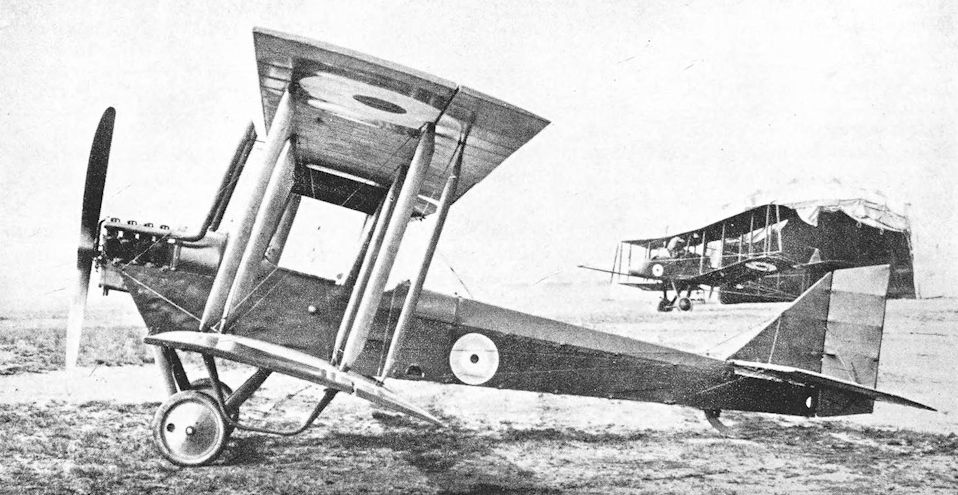
An Airco-built aircraft, B2840, in the so-called D.H.6A configuration with back stagger and reduced rudder and elevator chord.
Production D.H.6 with reduced under-camber, negative stagger, small rudder and small elevators. In the background is an F.E.2b fitted with balloon fenders.
Production D.H.6 with reduced under-camber, negative stagger, small rudder and small elevators. In the background is an F.E.2b fitted with balloon fenders.

D.H.6 with Curtiss engine.
D.H.6A of No.242 Squadron. Newhaven.
D.H.6A of No.242 Squadron. Newhaven.
de Havilland 9
ON June 13th, 1917, German bombers attacked London in daylight and inflicted casualties which exceeded those caused within the County of London by all the Zeppelin attacks made up to that time. A few hours after the raid, Sir William Robertson, the Chief of the Imperial General Staff, asked for a substantial increase in the number of British aeroplanes. The German raid was proof enough of the potentiality of the aeroplane as a weapon of offence, and of the need for adequate means of defence; and the Cabinet agreed with Sir William Robertson that more British aircraft were urgently needed.
At a meeting held at the War Office on June 21st, 1917, it was decided to increase the service squadrons of the R.F.C. from 108 to 200; the majority of the new squadrons were to be equipped with bombing aircraft. Seven hundred D.H.4s were ordered at the end of June, 1917, for the equipment of the new bombing squadrons, and Sir Douglas Haig was told that development of a machine with longer range than the D.H.4 would be undertaken in order to permit the ultimate extension of the area of bombing operations.
On July 23rd, 1917, the Controller of Technical Design laid before the Air Board plans of an extensively modified version of the D.H.4 which, it was claimed, would have a speed of 112 m.p.h. at 10,000 feet and a greater range. The modifications were so extensive that the machine had to be regarded as a new type, and was given the type number D.H.9. The Air Board did not immediately decide to abandon the well-tried D.H.4, but, at their next meeting three days later, an assurance was given that the adoption of the new design would delay production by no more than three or four weeks. It was therefore decided to substitute the D.H.9 for the D.H.4 in the contracts which had already been let with contractors.
The prototype D.H.9 was A.7559, a modified D.H.4, and was flying in July, 1917. The engine was the 230 h.p. Galloway-built B.H.P., sometimes referred to as the Galloway Adriatic. This was the B.H.P. engine in its original form. The official choice fell upon the B.H.P. engine for the D.H.9’s power plant because it had been selected for very large scale production. Mass production of the 230 h.p. B.H.P. engine was made the special responsibility of the Siddeley-Deasy Car Co., who were then building some twenty-five to thirty standard B.H.P.s per week. Two thousand engines were ordered from Siddeley-Deasy. Delays occurred before modifications could be made to facilitate quantity production, and a major difficulty arose from the production of the aluminium cylinder blocks. Enough cylinder blocks were available by July, 1917, to permit production of the engines at the rate of too per month, but it was soon found that more than 90 per cent of the cylinder blocks were defective. The modified engine had been named the Siddeley Puma and the first few were rated at 300 h.p., but these gave so much trouble owing to faulty cylinder blocks that the engine was de-rated to 230 h.p. Perhaps the original output of 300 h.p. was responsible for the first optimistic estimates of the D.H.9’s performance.
That these estimates would not be realised was known before the D.H.9 came into service. This information reached Major-General H. M. Trenchard in November, 1917, and on the 16th of that month he wrote to Major-General J. M. Salmond, then Director-General of Military Aeronautics, to say that he had learned unofficially from Mr Geoffrey de Havilland that the performance of the D.H.9 would be poorer than that of the Rolls-Royce-powered D.H.4, and that the new machine would be unable to reach 15,000 feet fully loaded. Major-General Trenchard went on: “I do not know who is responsible for deciding upon the D.H.9, but I should have thought that no-one would imagine we should be able to carry out long-distance bombing raids by day next year with machines inferior in performance to those we use for this purpose at present. I consider the situation critical. ... I am strongly of opinion that unless something is done at once we shall be in a very serious situation next year. ...” Major-General Salmond placed these representations before the Air Board, but was informed by Sir William Weir that the choice was between the B.H.P.-powered D.H.9 or nothing at all.
On November 14th Sir Douglas Haig, inspired by Major-General Trenchard, had asked for orders for D.H.9s to be reduced to limit their use to no more than fifteen squadrons, because the type would be outclassed as a day bomber by June, 1918.
But it was too late. As with the B.E.2c and 2e earlier in the war, the official decision had been taken to standardise the D.H.9, and production was too far advanced for a change to be made. Ultimately, production of the Siddeley Puma engine reached 200 per week, and D.H.9s were turned out at the rate of one every forty minutes.
The squadrons who had to fly the type had to make the best of a bad job, and there was a world of truth in the wry description of the D.H.9 as a “D.H.4. which has been officially interfered with in order to be suitable for mass-production and the B.H.P. motor”.
In construction the D.H.9 was identical to the D.H.4: indeed, the wings and tail unit were the same in every respect. The most obvious external differences between the D.H.9 and D.H.4 lay in the engine installation and the disposition of the cockpits. The later machine made a breakaway from contemporary British practice by having a retractable radiator placed under the fuselage instead of arranged round the airscrew shaft. The cowling of the engine gave the nose of the D.H.9 a “Hunnish” appearance, but the cylinders and exhaust manifold formed an inelegant excrescence. The revised cockpit arrangement was probably the only improvement over the D.H.4: pilot and observer were close together and were able to communicate instantly and easily with each other. The pilot was also spared the unenviable position he occupied in the D.H.4, between the engine and fuel tanks. Nevertheless, the farther aft position of the pilot gave rise to criticism because the forward and downward view was obscured by the lower wing. To improve matters a cut-out was made in the root of the lower starboard wing between the spars. The D.H.9’s gravity fuel tank was contained in the centre-section, between the spars.
The D.H.9 was, in short, a good aeroplane spoiled by a bad engine which, if the truth be told, was obsolete at the time it was adopted as the power unit. With the B.H.P. engine the D.H.9 was expected to lift a greater load than the more powerful D.H.4, and in doing so its ceiling and performance suffered so severely that it was an easy victim for the German fighting scouts, particularly when engine failure on several machines reduced the numbers of a formation and robbed it of some of its defensive fire-power. The D.H.9 was unable to maintain its height with full load at 15,000 feet, and was seldom able to fly above 13,000 feet. It was therefore at a severe tactical disadvantage.
The first production D.H.9s were completed late in 1917: five were delivered before the end of the year. The early machines had B.H.P. engines built by both the Galloway and Siddeley-Deasy concerns. The type was issued to the squadrons early in 1918. The first D.H.9s in France were those of Squadrons Nos. 98, 206 and 211, all of which were in France at the beginning of April, 1918. Nos. 98 and 206 were with the II Brigade, and participated in the Battle of the Lys. On April 12th, nineteen pilots of No. 206 Squadron flew a total of 76 hours, and on that day No. 98 mounted no less than six sorties.
The name of the D.H.9, like that of the Handley Page O/400, will probably be forever linked with that of the Independent Force. In May, 1918, Squadrons Nos. 99 and 104 joined the VIII Brigade, the forerunner of the Independent Force: No. 99 arrived in France on May 3rd, No. 104 on May 19th. The squadrons supplemented the work of the D.H.4s of No. 55 Squadron, and made their first raids on May 21 st and June 8th respectively. These two units carried out eighty-three raids before the Armistice. That total represented 848 machine-sorties: of these, no fewer than 123 had to return with engine trouble. During the period, No. 99 Squadron lost twenty-one D.H.9s and 104 Squadron thirty-three to enemy action, and a further ninety-four machines were otherwise wrecked.
The D.H.9’s operational showing did nothing to enhance Major-General Trenchard’s opinion of it. His prophecy that the machine would be outclassed by June, 1918, was soon fulfilled; and writing in that month he said it was imperative that every effort should be made to replace the D.H.9 by tbe Liberty-powered D.H.9A. By the end of August, 1918, Major-General Trenchard decided that the D.H.9 could no longer be regarded as a front-line type: the losses which must be expected from the continued use of the type did not justify sending the D.H.9 squadrons over the lines.
In his report on the work of the R.A.F. on the Western Front during October, 1918, Major-General J. M. Salmond said of the D.H.9 "... although this type of aeroplane has sufficient petrol, and oil, to enable it to reach objectives too miles from the lines, its low ceiling and inferior performance oblige it to accept battle when, and where, the defending forces choose, with the practical result that raids tend to become restricted to those areas within which protection can be afforded by the daily offensive patrols of scout squadrons....”
Of the melancholy events which inspired Major-General Salmond’s report, none was worse than the experience of No. 99 Squadron on July 31st, 1918. Twelve D.H.9s of the squadron set out at 5.30 a.m. that morning to attack Mainz but, true to form, engine trouble forced three of the formation to return. Over Saaralbe, enemy scouts attacked and shot down one D.H.9, and a subsequent onslaught by about forty enemy machines near Saarbrucken shot down three more D.H.gs. The five survivors battled on as far as Saarbrucken and dropped their bombs on the railway station; but the enemy fighters maintained their attack and another D.H.9 crashed near the centre of the town. Two more fell on the homeward journey: only the leader, Captain A. H. Taylor, and one other pilot brought their D.H.9s back to No. 99’s aerodrome at Azelot.
The enemy did not escape scot free. Part of Captain Taylor’s report reads: “We also accounted for eight enemy scouts definitely known to have crashed. ... We lost seven machines. ... I recommend that we return and finish the job.” But the squadron had lost fourteen experienced officers, and was unable to resume its work until the replacements had been adequately trained in formation flying.
Despite Major-General Trenchard’s decision of late August, the D.H.9 remained operational until the Armistice; indeed, so persistent were those in authority that it replaced the superior D.H.4 in several squadrons. Until the end, however, the D.H.4 was treated with greater respect than the D.H.9 by the enemy fighters. To the last, the D.H.9s were let down by their engines: on October 1st, 1918, of twenty-nine D.H.9s sent by Nos. 27 and 98 Squadrons to bomb the railway junction at Aulnoye, no fewer than fifteen had to turn back with engine trouble, and the depleted formation was unable to attack its objective.
On other fronts D.H.9s played a rather more successful part in achieving victory. In Palestine, those of No. 144 Squadron took part in the sustained attacks on the retreating Turks, on September 19th, 1918, on the Tul Karm-Nablus road, and two days later in the Wadi el Far‘a. On September 23rd, the attacks made by the D.H.9s on Mafraq station and on enemy columns on the Es Salt-‘Amman road helped to hasten the defeat of the Turks.
In Macedonia, No. 47 Squadron received its first D.H.9 on August 2nd, 1918, and “A” Flight of that unit was completely equipped with the type by August 21st, 1918. No. 17 Squadron similarly received a Flight in September, and each squadron had six D.H.9s at the time of the Armistice. The new aircraft made long-range reconnaissances possible, and frequently carried out flights of 300 miles. Between September 1st and 29th, the D.H.9s of No. 47 Squadron flew a total of 315 1/2 hours. In this theatre of war the D.H.9 was, in fact, used more for reconnaissance work than for bombing, but on September 21st the D.H.9s participated in the attacks on the retreating Bulgarian army caught in the Kosturino Pass.
The D.H.9s operating from the Aegean islands made serious attempts to bomb Constantinople by night and day: the flight was one of about 440 miles and took some 5 1/2 hours. The machines were fitted with “home-made” extra fuel tanks which increased their endurance to 5 3/4 hours. Thus, the margin of safety was so narrow that many of the D.H.9s failed to reach their home aerodromes, and landings were perforce made elsewhere, occasionally in the sea.
Coastal aerodromes in the United Kingdom received the D.H.9 in 1918 for anti-Zeppelin work and for escorting the big flying boats. One of the D.H.9s from Great Yarmouth air station (No. 212 Squadron, R.A.F.) attacked the Zeppelin L.65 on the night of August 5th/6th, 1918. It did not succeed in destroying the airship, but was itself lost in mysterious circumstances. Towards the end of the war, D.H.9s began to replace D.H.6s for anti-submarine patrols.
Since the B.H.P. engine was so unreliable, it is regrettable that history does not tell more about the D.H.9s which had the 250 h.p. Fiat A-12 engine. Two thousand engines of this type had been ordered in August, 1917, at the instigation of Sir William Weir. The contract stipulated that deliveries were to be made between January and June, 1918, and it was intended to allocate 1,000 engines to America and to use the other thousand in D.H.9s. Only a tenth of that number were so used, however: early installations of the Fiat were made in the D.H.9s numbered C.6052 and D.5748, and 100 Fiat-powered machines (numbered D.2776-D.2785) were ordered from Short Brothers.
The Fiat A-12 was a six-cylinder in-line engine, and its similarity in configuration to the B.H.P. resulted in a generally similar installation. The Fiat could be distinguished by its exhaust manifold on the starboard side; that of the B.H.P. was on the port.
In October, 1918, a D.H.9 was tested with the high-compression version of the Siddeley Puma, which gave 290 h.p. This engine made no appreciable improvement in the aircraft’s performance, however.
In the summer of 1917 the firm of D. Napier & Son designed an aero-engine of unusual configuration: it was a twelve-cylinder engine with cylinders arranged in three groups of four, which were disposed in the form of a broad arrow. At first this engine was known as the Napier Triple-Four, and in September, 1917, the manufacturers envisaged a power output of 300 b.h.p. at 10,000 feet.
The new engine was named the Napier Lion, and early in 1918 one of the prototype Lions was installed in the D.H.9 numbered C.6078. Early trials at Farnborough showed that the heating of the induction system was inadequate. The application of hot-water jackets and lagging to the induction pipes, of water jackets to the carburettor throttles, and of exhaust-heated jackets to the air intakes, proved to be of little use.
Development proceeded and, after the initial difficulties had been overcome, it became evident that the Lion was an excellent engine and one which would have been of great benefit to the D.H.9. By June, 1918, the Lion-Nine was returning good performance figures, and shortly afterwards C.6078 was fitted with the first production Napier Lion engine. The airframe was strengthened in several ways: at the forward end of the fuselage additional three-ply webs were fitted and steel plates were applied to cross-members; at the tail the bottom longerons were reinforced by ash strips; the front spar of the tailplane was reinforced, and steel tube bracing struts were fitted; and thicker plywood was applied to the centresection. The retractable radiator was increased in size.
With this engine the D.H.9 at last had a worthwhile performance. It was delivered to Martlesham Heath for service trials at the beginning of October, 1918. While there the machine was flown by Captain Andrew Lang to a height of 30,500 feet, a new world’s record at the time. The climb was made on January 2nd, 1919, and occupied 66 minutes 15 seconds. Lang’s observer was Lieutenant Blowes.
The American Expeditionary Force bought two D.H.9s in July, 1918. These machines were delivered without engines, and were used to test the installation of the 400 h.p. Liberty 12-A engine in the airframe. One went to America, for it was intended to produce the type there, powered by the Liberty engine. The projected scale of American manufacture made even the highly creditable rate of British production look somewhat amateurish, for no fewer than 14,000 aircraft were ordered. In October, 1918, four D.H.9s were in service with the U.S. Naval Northern Bombing Group in France, but it is uncertain whether they were American-built machines. An American-designed development of the D.H.9 was built under the designation USD-9. Four USD-9s were delivered in August, 1918: two were built by Dayton-Wright and two by the Engineering Division of the Bureau of Aircraft Production. All contracts were cancelled after the Armistice.
In 1918 eighteen D.H.9s were supplied to the Belgian Flying Corps, presumably for use as day bombers.
The D.H.9 remained on active service with the R.A.F. after the Armistice. In Russia, Nos. 47 and 221 Squadrons were equipped with a mixture of D.H.9s and D.H.9As for service with Denikin’s White Army in 1919. So intense was the cold that water had to be boiled and oil heated before the radiators and sumps of the aircraft could be filled. One captured machine was operated by the Reds towards the end of the campaign.
After the war the D.H.9 was used for a few years by the R.A.F., but was withdrawn in favour of the superior D.H.9A. It took some time for the D.H.9s to be disposed of, but other nations took advantage of the low price at which the Aircraft Disposals Co. sold the discarded machines.
The D.H.9 did a vast amount of pioneering work in the field of commercial aviation, and several modified versions appeared in the post-war years. The type was used for experimental purposes with Handley Page slots and in Sir Alan Cobham’s early experiments in flight refuelling. Some of the Commonwealth countries used D.H.9s, and those of the South African Air Force survived until 1937 in a much modified form known as the Mpala, which was powered by a Bristol Jupiter radial engine.
SPECIFICATION
Manufacturers: The Aircraft Manufacturing Co., Ltd., Hendon, London, N.W.
Other Contractors: The Alliance Aeroplane Co., Ltd., Cambridge Road, Hammersmith, London; F. W. Berwick & Co., Ltd., Park Royal, London, N.W. 10; Cubitt, Ltd., Croydon; Mann, Egerton & Co., Ltd., Aircraft Works, Norwich; National Aircraft Factory No. 1, Waddon; National Aircraft Factory No. 2, Heaton Chapel, near Stockport; Short Brothers, Rochester, Kent; The Vulcan Motor & Engineering Co. (1906), Ltd., Crossens, Southport; Waring & Gillow, Ltd., Cambridge Road, Hammersmith, London (and Wells Aviation Co., Ltd., 30 Whitehead’s Grove, Chelsea, London, S.W.8, under sub-contract); G. & J. Weir, Ltd., Cathcart, Glasgow; Westland Aircraft Works, Yeovil, Somerset; Whitehead Aircraft Co., Ltd., Old Drill Hall, Townshend Road, Richmond.
Power: 230 h.p. B.H.P. (Galloway Adriatic); 230 h.p. Siddeley Puma; 290 h.p. Siddeley Puma (high compression) ; 250 h.p. Fiat A-12; 430 h.p. Napier Lion; 400 h.p. Liberty 12-A.
Dimensions: Span: 42 ft 4 5/8 in. Length (B.H.P. and Puma): 30 ft 6 in., (Lion) 30 ft 9 1/2 in., (Liberty) 30 ft. Height: 11 ft 2 in. (with Lion, 11 ft 7 3/4 in.). Chord: 5 ft 6 in. Gap: 5 ft 6 in. Stagger: 12 in. Dihedral: 3. Incidence: 3. Span of tail: 14 ft. Wheel track: 6 ft. Tyres: 750 X 125 mm. Airscrew diameter: four-bladed, 8 ft 9 in.; two-bladed, 9 ft 6 1/2 in.; Napier Lion, 11 ft.
Areas: Wings: upper 223 sq ft, lower 211 sq ft, total 434 sq ft. Ailerons: each 20-5 sq ft, total 82 sq ft. Tailplane: 38 sq ft. Elevators: 24 sq ft. Fin: 5-4 sq ft. Rudder: 13-7 sq ft.
Tankage: On the prototype D.H.9 (A.7559) fuel tanks were as follows: petrol: two tanks behind engine, 30 gallons each, one gravity tank in centre section 10 1/2 gallons; total 70 1/2 gallons. Oil: under sump (forced feed) 5 gallons. Water: 7 1/2 gallons. On production D.H.9s: petrol: two tanks behind engine, one of 34 gallons, the other of 28 gallons, one gravity tank 8 gallons; total 70 gallons. Oil: under engine crank-case (B.H.P.) 4 1/2 gallons, (Napier Lion) 7 gallons. Water: 6 1/2 gallons.
Armament: One fixed forward-firing Vickers machine-gun mounted on top of fuselage immediately to the left of the pilot’s windscreen and synchronised by Constantinesco G.C. Gear. Loading handle: Hyland Type B. The observer had either a single Lewis machine-gun or a double-yoked pair on a Scarff ring-mounting on the rear cockpit. Bomb racks were fitted under the fuselage and under each lower wing; the bomb release-gear was of the Gledhill type. The bomb load consisted of two 230-lb bombs, three or four 112-lb bombs, or an equivalent weight of smaller bombs.
Service Use: Western Front: R.A.F. Squadrons Nos. 27, 49, 98, 99, 103, 104, 107, 108, 202, 206, 211 and 218. Used by Belgian Flying Corps, and a few saw service with the U.S. Naval Northern Bombing Group. Sea Patrol: No. 212 Squadron, Great Yarmouth; No. 250 Squadron, Padstow; No. 273 Squadron (Flights at Govehithe and Westgate). Palestine: No. 144 Squadron. Macedonia: Nos. 17 and 47 Squadrons. Mediterranean: Nos. 224, 225, 226 and 227 Squadrons. Aegean: Nos. 220, 221, 222 and 223 Squadrons. Russia: No. 47 Squadron at Ekaterinodar, No. 221 at Petrovsk. Training: Air Observers’ Schools at Eastchurch, Manston and New Romney; School of Photography, Maps and Reconnaissance at Farnborough; Schools of Navigation and Bomb Dropping at Stonehenge, Andover and Thetford. Also used by No. 10 Training Depot Squadron, Harling Road; No. 31 Training Squadron, Wyton; and at Cranwell and Shoreham.
Production and Allocation: By the end of 1918, a total of 3,204 D.H.9s were built. Of these 2,166 were distributed to R.A.F. units before October 31st, 1918, as follows: to squadrons with the B.E.F., 789; to the Independent Force, 144; to the squadrons of the 5th Group (for naval cooperation), fifty-two; to the Middle East Brigade, ninety-two; to the Mediterranean, 133; to training units, 956. In addition, eighteen were supplied to the Belgian Flying Corps in 1918; and America bought two without engines in July, 1918. On October 31st, 1918, the R.A.F. had 1,866 D.H.9s on charge. In France, 334 were with the B.E.F., seventy-one with the Independent Force, and four with the 5th Group. Seven were in Egypt and Palestine, twenty-one at Salonika, and seventy-eight were at Mediterranean stations; 135 were on the way to Eastern stations. At home, 184 were at training units; thirty-seven were with squadrons mobilising; 424 were at various aerodromes; one was in use for anti-submarine patrol; twenty-four were at Aeroplane Repair Depots; forty-one were with the nth Group in Ireland; 186 were with contractors; and 319 were in store.
Serial Numbers:
Serial Nos. Contractor Contract No.
A.7559 Aircraft Manufacturing Co. Converted under A.S.21273/1/17, supplied under A.S.17569
B.7581-B.7680 Westland Aircraft A.S.17570
B.9331-B.9430 Vulcan Motor & Engineering Co. 87/A/1413
C.1151-C.1450 G. & J. Weir A.S.17570
C.2151-C.2230 Berwick & Co. 87/A/1185
C.6051-G.6121
C.6123-C.6349 Aircraft Manufacturing Co. A.S.17569
D.451-D.950 Cubitt A.S.26928
D.1001-D.1500 National Aircraft Factory No. 2 A.S.32754
D.1651-D.1750 Mann, Egerton A.S. 17994
D.2776-D.2875 Short Brothers (Fiat engines) A.S.34886
D.2876-D.3274 Aircraft Manufacturing Co. A.s.17569
D.5551-D.5850 Waring & Gillow (50 machines were built by Wells Aviation Co. under sub-contract) A.S.20391
D.7201-D.7300 Westland Aircraft A.S.42381
D.7301-D.7400 Berwick & Co. A.S.37725
D.9800-D.9899 G. & J. Weir A.s.41634
E.601-E.700 Whitehead Aircraft A.S.2341
E.5435-E-5436 Aircraft Manufacturing Co. A.s.17569
E.8857-E.9056 Aircraft Manufacturing Co. 35A/4I8/C.296
F.1-F.300 National Aircraft Factory No. 1 35A/409/C.297 (only 241 completed)
F.1101-F.1300 Waring & Gillow 35A/4I6/C.295
F.1767-F.1866 Westland Aircraft A.s.19174
Between and about
H.5546 and H.5738 Alliance Aeroplane Co. -
Between and about
H.9133 and H.9340 -
Notes on Individual Machines: Used by No. 49 Squadron: C.2202, C.6114, C.6116, C.6135, C.6175, D.457, D.461, D.3052, D.5576, D.5585, D.5596, E.623. Used by No. 98 Squadron: C.2221, C.6079, C.6106, C.6108, G.6119, D.3060, D.3169. Used by No. 103 Squadron: G.1213, C.2224, D.489, D.496, D.1003, D.2857, D.2866, D.3046. Used by No. 211 Squadron: B.7603, C.6270, D.2782, D.3233. Used at No. 1 School of Navigation and Bomb Dropping, Stonehenge: C.1320, C.2171, G.6128, D.1677, D.5681. Used at Manston: D.476, D.479, D.3028, D.5672. Other machines: A.7559: prototype D.H.9, fitted with Galloway-built B.H.P. engine No. 11, W.D.15434. B.9395: “The Mackenzie Tooloombah”. G.6051: Siddeley-built B.H.P. engine No. 5019, W.D.22693. C.6052: Fiat engine. G.6078: Napier Lion engine. D.3010 and D.3015: No. 186 Development Squadron, Gosport, 1919. D.5748: Fiat engine. D.5806: No. 186 Development Squadron, Gosport. E.8888: No. 186 Development Squadron, Gosport. F.1181: presented to Canada, February, 1919. F.1222: “Australia No. 26, Queensland No. 2, The Banchory”. F.1227: “Australia No. 27, Victoria No. 2, The Murroa”. F.1255: presented to Canada, February, 1919.
Costs:
Airframe without engine, instruments and guns £1,473 5s.
Siddeley Puma engine £1,089 0s.

D.H.9, C.6078, with prototype Napier Lion engine.

D.H.9, C.6078, with the first production Napier Lion engine.

Standard production D.H.9 built by Mann, Egerton & Co.

D.H.9 with Fiat engine.

D.H.9 used in experiments with silencers, fitted with long exhaust pipe and night-flying equipment.
de Havilland io and 10A, the Amiens
PROOF that the promise of the D.H.3 of 1916 had not been forgotten was provided early in 1918, when the first D.H.10 appeared. The relationship between the two machines was at once obvious, for the D.H.10 had the same underslung fuselage and wide-track split undercarriage. It was a three-seater designed for bombing duties, and was rather larger than the D.H.3.
The initial contract was for four prototypes. The first machine was powered by two 230 h.p. B.H.P. engines installed as pushers, thus duplicating the engine arrangement used on the earlier D.H.3, and also had two auxiliary wheels at the nose. There were cut-outs in the trailing edges of the wings to allow the airscrews to revolve. In this form the D.H.10 first flew on March 4th, 1918. Performance at an all-up weight of 6,950 lb was quite good, but it seems probable that this figure did not include an exceptionally large bomb load. An idea of using the original D.H.10 as a Home Defence aircraft seems to have been short-lived.
More powerful engines were tried in the other prototypes. The second machine, C.8659, had two 360 h.p. Rolls-Royce Eagle VIII engines installed as tractors, each driving a two-bladed airscrew. This machine first flew on April 20th, 1918. Both prototypes had plain ailerons which extended inboard as far as the second pair of interplane struts, and on C.8659 there were, of course, no cut-outs in the trailing edges of the wings.
The third prototype, C.8660, had two Liberty 12 engines driving two-bladed tractor airscrews. On this D.H.10 the Liberties were housed in rather massive nacelles which extended behind the trailing edges of the wings. The sweep-back of the mainplanes was slightly reduced and the ailerons were shorter than those of the first two prototypes, but a refinement was added in the shape of horn balances. With the Liberty engines the D.H.10 had an excellent performance, and it was this version which went into production. The shape of the nose was slightly modified, and the twin nosewheels were not fitted.
The type was officially named Amiens, but, strangely, the name has not survived. The first prototype with B.H.P. engines was designated Amiens Mk. I; the second, Eagle-powered, machine was the Mk. II, and the Liberty D.H.10 was the Amiens Mk. III.
Structurally, the D.H.10 differed little from its predecessors. The fuselage was a wooden structure: the forward portion was a plywood-covered box and the rear part was a conventional wire-braced boxgirder with fabric covering. The two parts were butt-jointed immediately behind the rear gunner’s cockpit. All longerons and spacers were of spruce. The lower centre-section was built integral with the fuselage: the spars entered the fuselage and were divided on the aircraft centre-line, where they were connected by special star-shaped brackets. The two lowest arms of these brackets held the upper ends of two oblique bracing struts which arose from the lower longerons, and the central top arm accommodated the bottom of each single centre-section strut.
The main fuel supply was carried in two 98-gallon tanks, one of which was situated immediately behind the pilot, and the other in front of the rear gunner’s cockpit. The space between the tanks was the bomb bay. A 19-gallon gravity tank was mounted in the upper centre-section. Dual control was provided in the rear gunner’s cockpit: the rudder bar was normally concealed by two doors in the floor of the cockpit.
The wings were conventional in construction. Spars were of laminated spruce; compression ribs were of ash three-ply with spruce capping; and the internal cross-bracing was of 2 B.A. tie rods. The aileron control cables ran inside the wings. The interplane struts were of silver spruce, and single Rafwires were used for bracing. The struts which carried the engine-bearers were of faired steel tube.
The tailplane had spruce spars, and its incidence could be controlled from the cockpit. The elevators had steel tube trailing edges. The fin and rudder were built in similar fashion; the fixed surface was wholly made of wood, whilst the trailing edge of the rudder was of steel tubing.
The eminently sensible undercarriage relied on rubber cord for shock absorption: 26 feet of 5/8-inch diameter cord was used on each side. The tail-skid was of steel-shod ash, and had three rubber cord springs.
The first three contracts, for a total of 450 aircraft, were placed on March 10th, 1918, just over two weeks after the first flight of the prototype. Production D.H.10s were not delivered early enough to enable the type to be tested in action, however, for by October 31st, 1918, the R.A.F. had only eight D.H.10s on charge, and only two of those had reached the Independent Force. Had the war continued, the D.H. 10 could hardly have failed to prove to be an effective weapon with its fine performance, useful bomb load and good defensive armament.
It was reported to be pleasant to fly, but some trouble was experienced with the fuel pumps, which were driven by small airscrews revolving freely in the airstream. These drove the pumps at air speeds above 70 m.p.h., but at lower air speeds the pumps were not so efficient, and one engine would be starved of fuel. The results of this could be unpleasant, especially at take-off, and caused some adverse criticism of the type before the difficulty was overcome.
An improvement in performance was made by revising the position of the engines so that each was attached directly to the lower mainplane. This power installation was cleaner than the original, for it eliminated the struts which, in the D.H.10, supported each engine. With the revised engine arrangement the type was designated D.H.10A by the manufacturers, and was officially styled Amiens Mk. IIIa.
Although neither the D.H.10 nor the D.H.10A took an active part in the war, two D.H.10s were allotted to an Experimental Armament Unit for experiments with the Coventry Ordnance Works 1 1/2-pounder quick-firing gun. One of these two machines had Rolls-Royce Eagle engines and may have been the second prototype. The other D.H.10 had Liberty engines, and was the only one of the two in which the gun was tested. The weapon was mounted in the nose cockpit, and in addition to the gunner an observer was carried in the rear seat. This D.H.10 crashed during the armament experiments, but it seems that the Eagle-powered machine was not used even then.
The D.H.10 was one of the aeroplanes which took part in the early post-war air-mail flights, especially on the R.A.F.’s air-mail service for the British Army of Occupation; this service began on March 1st, 1919. The terminal points of the route were Hawkinge and Cologne, and transportation of the mails was regarded as a normal duty of No. 120 Squadron. This unit had some D.H.10s on its strength, and it was a D.H.10 which gained the distinction of being the first aeroplane to carry mail at night. The first experimental night-mail flight was made on the night of May 14th/15th, 1919, by a D.H.10 manned by Captain Barrett, Lieutenant Fitzmaurice and Lieutenant Oliver, who left Hawkinge at 10.15 p.m. on May 14th and reached Cologne at 1.30 a.m. the following morning.
In addition to its good work on the early air-mail routes the D.H.10 was flown by the R.A.F. on the North-West Frontier of India during the early 1920s. Some of the machines used in India had an additional cockpit immediately behind the pilot and in line with the leading edge of the lower wing.
A late development of the design was the D.H.10C, officially designated Amiens Mk. IIIc. This version had two 375 h.p. Rolls-Royce Eagle VIII engines mounted in D.H.10A style directly on the lower mainplane. It is probable that this engine change was made because of the cessation of deliveries of the Liberty engine in July, 1918, and it was intended to put the D.H.10C into production: one of the contractors for the type was to have been the Mann, Egerton company. The prototype D.H.10C, E.5557, was used during 1919 by Aircraft Transport and Travel, Ltd., the subsidiary of the Aircraft Manufacturing Co. It was then based at Hendon.
The designation D.H.10B is usually attributed to the civil-registered D.H.10 G-EAJO, which was modified for the carriage of air-mail.
A D.H.10 participated in a series of experiments which were conducted to investigate the controllability of twin-engined aircraft in the event of failure of one engine. At first, the single fin and rudder were replaced by twin fins and horn-balanced rudders mounted wholly above the tailplane. These new surfaces were more or less of typical D.H. outline, and were mounted at three different angles: parallel, toed-in at 7 1/2 degrees and toed-in at 15 degrees. Each fin was 9-5 sq ft in area; each rudder 19-5 sq ft.
From this tail-unit was developed another with twin fins and rudders. This had vertical surfaces of angular outline which extended above and below the tailplane; cut-outs were made in the elevators to permit rudder movement. Total fin area on each side was 12-5 sq ft, and each rudder was 12-5 sq ft.
A third experimental tail-unit consisted of a rectangular fin of low aspect-ratio, 19 sq ft in area, and a large horn-balanced rudder of 39 sq ft. This rudder was at first over-balanced, and the balance area was twice reduced before it became satisfactory.
SPECIFICATION
Manufacturers: The Aircraft Manufacturing Co., Ltd., Hendon, London, N.W.
Other Contractors: The Birmingham Carriage Co., Birmingham; The Daimler Co., Ltd., Coventry; National Aircraft Factory No. 2, Heaton Chapel, near Stockport; The Siddeley-Deasy Motor Car Co., Ltd., Park Side, Coventry; The Alliance Aeroplane Co., Ltd., Cambridge Road, Hammersmith, London, W.14; Mann, Egerton & Co., Ltd., Norwich.
Power: Amiens Mk. I: two 230 h.p. B.H.P., installed as pushers. Amiens Mk. II: two 360 h.p. Rolls-Royce Eagle VIII. Amiens Mk. III and IIIa: two 400 h.p. Liberty 12. Amiens Mk. IIIc: two 375 h.p. Rolls-Royce Eagle VIII.
Dimensions: Span: Mks. I and II, 62 ft 9 in.; Mks. Ill and IIIa, 65 ft 6 in. Length: Mks. I and II, 38 ft 10 1/8 in.; Mks. Ill and IIIa, 39 ft 7 7/16 in. Height: 14 ft 6 in. Chord: 7 ft. Gap: 7 ft. Dihedral: 4 30'. Incidence: 7. Sweep-back: Mk. II, 40; Mks. Ill and IIIa, 2 30'. Span of tail: 22 ft. Airscrew diameter (Liberty): 10 ft.
Areas:
Mk. II Mks. Ill and IIIa
Wings, upper 427-4 sq ft 429-2 sq ft
lower 407-4 sq ft 408-2 sq ft
total 834-8 sq ft 837-4 sq ft
Ailerons, each 30-2 sq ft 29-5 s9 ft
total 120-8 sq ft 118-0 sq ft
Tailplane 71-6 sq ft 75-5 sq ft
Elevators 46-0 sq ft 33-08 sq ft
Fin 10-0 sq ft 10-0 sq ft
Rudder 25-75 sq ft 25-75 sq ft
Tankage: Petrol: two main tanks, 98 gallons each; gravity tank, 19 gallons; total, 215 gallons. Oil: two tanks, 7 gallons each; total, 14 gallons.
Armament: Both nose and rear cockpits were fitted with a Scarff ring-mounting, and each bore either a single Lewis gun or a double-yoked pair. The main bomb load could be carried internally, but additional external racks were also fitted under the lower wings. About 900 lb of bombs could be carried. Experimentally, one D.H. 10 had a 1 1/2-pounder Coventry Ordnance Works gun in the front cockpit.
Service Use: No. 120 Squadron, R.A.F.
Production and Allocation: A total of 1,295 D.H. 10s were ordered, but all were not delivered. On October 31st, 1918, the R.A.F. had only eight on charge, of which only two were in France with the Independent Force. Earlier in 1918 one D.H. 10 had been delivered to a Home Defence station.
Notes on Individual Machines: C.8659 was Amiens Mk. II; C.8660 was Amiens Mk. Ill prototype. E.5507: used in India, had extra cockpit behind pilot. E.5557: became D.H.10C. E.6042: D.H. 10 later fitted with twin fins and rudders. E.7851: used in India, extra cockpit. F.1869: D.H.10A. F.1874: D.H.10. F.8421: D.H.10A.
Serial Numbers:
Serial Nos. Contractor
C.8658-C.8660 Aircraft Manufacturing Co.
E.5437-E.5636 Aircraft Manufacturing Co.
E.6037-E.6136 Birmingham Carriage Co.
E.7837-E.7986 Siddeley-Deasy
E.9057-E.9206 Daimler, Ltd.
F.351-F.550 National Aircraft Factory No. 2
F.1867-F.1882 Aircraft Manufacturing Co.
F.7147-F.7346 Alliance Aeroplane Co.
F.8421-F.8495 Mann, Egerton & Co.
H.2746-H.2945 Aircraft Manufacturing Co.
Costs:
D.H.10 (Liberty) airframe without engines, instruments and guns £3,483 7s.
Liberty engine (each) £1,215 0s.
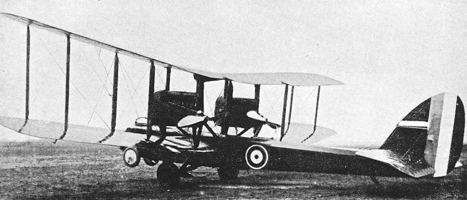
First prototype D.H.10, Amiens Mk. I, with two B.H.P. engines installed as pushers.
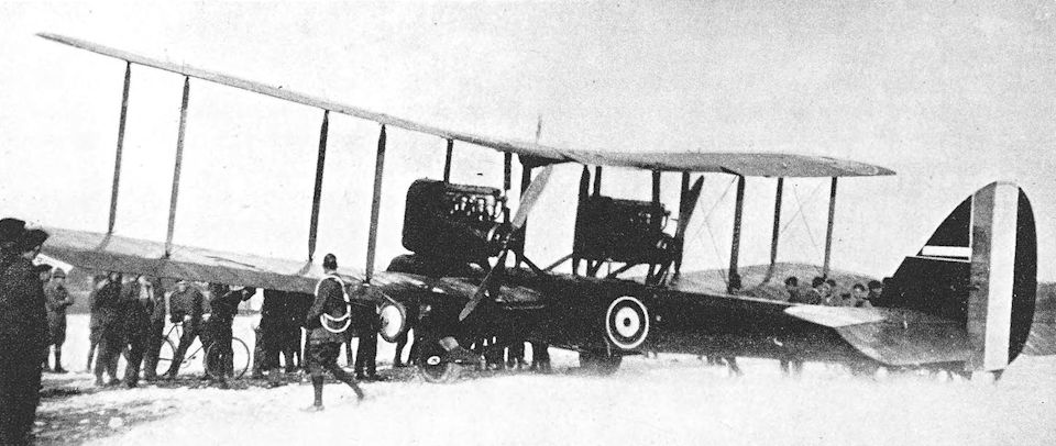
The first prototype D.H. 10 with two 230 h.p. B.H.P. engines arranged as pushers. The cutaway main plane trailing edge was unique to this aircraft.
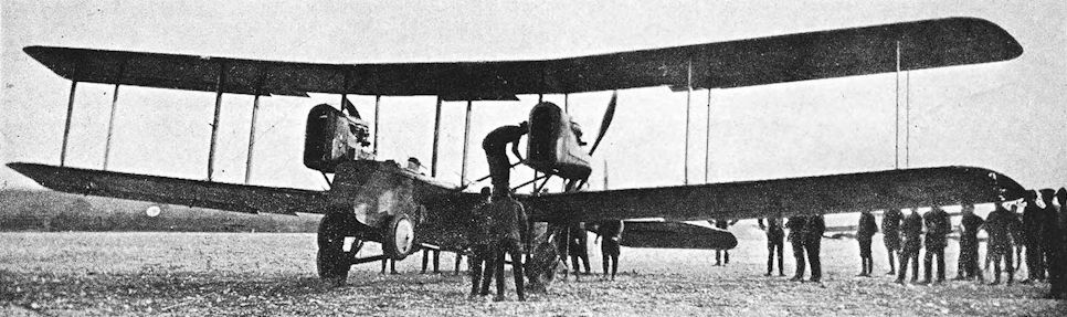
An early photograph of the first D.H. 10, taken before the Scarff ring-mountings were fitted to the front and rear cockpits.
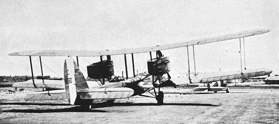
Third prototype D.H.10, Amiens Mk. III, serial number C.8660, with Liberty engines.
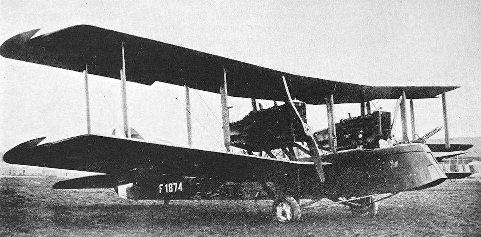
Production D.H.10.
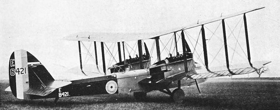
Delivered to the RAF on 1 March 1919, F9421 was the first Mann, Egerton-built Amiens IIIa; most of these aircraft were issued to No 60 Squadron on the North-West Frontier.
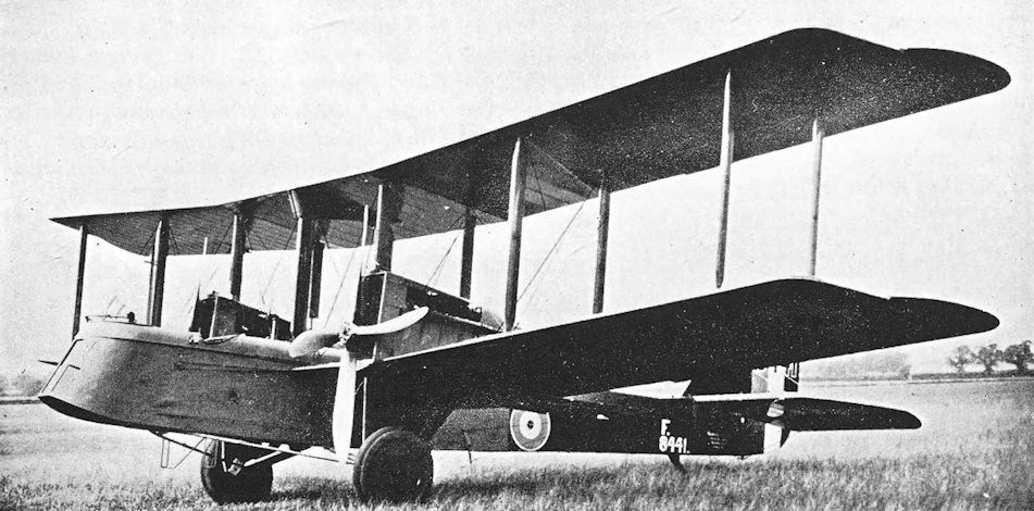
de Havilland 10C, Amiens Mk. IIIc, built by Mann, Egerton & Co.
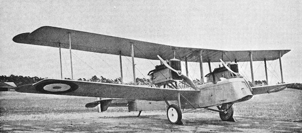
D.H.10, E.6042, with twin fins and rudders.
de Havilland 9A
THE story of the designing of the American Liberty engine was launched in a blaze of publicity on August 12th, 1917, when an official statement was issued by the American Secretary of War. This statement described how the first engine was completed only twenty-eight days after the drawings were commenced, unquestionably a fine engineering achievement, and went on to describe the sterling qualities of the new power unit in glowing terms. The description of the first Liberty as “the best aircraft engine produced in any country” was somewhat premature, however, for it had not flown at the date of the Secretary of War’s statement.
The first Liberty was an eight-cylinder vee engine, designed by Major J. G. Vincent of the Packard company and Major J. G. Hall of the Hall-Scott company, who first met to discuss the design requirements on June 3rd, 1917. The first engine was assembled on July 3rd, 1917, underwent its first bench test on July 23rd, and was flown for the first time on August 20th.
The construction of a twelve-cylinder version was also put in hand. This engine successfully completed a fifty-hour bench test on August 25th, 1917, and was originally rated at 314 h.p. The output was increased to 395 h.p. by October, in which month the engine was first flown in a D.H.4, and in December, 1917, serious development of the eight-cylinder model was abandoned in favour of the bigger engine.
Production of the Liberty 12 had already begun, but the original programme was over-ambitious and was never realised: the monthly output which was envisaged was 4,800, which was to be reached by May, 1918. Total deliveries by the end of that month were to reach a figure of 9,420, but in fact only 1,100 Liberty engines had been produced by that date. Production was delayed by lack of jigs, tools and gauges, and the supposedly perfect engine was the subject of no fewer than 1,022 modifications between September, 1917, and February, 1918.
Nevertheless, the production of 1,100 engines in twelve months from the commencement of design was a considerable achievement.
The high power output of the engine made it an attractive proposition, and it appealed particularly to Britain as an alternative to the Rolls-Royce Eagle, production of which was falling short of demand. The Allied governments asked for large numbers of Liberties, and by the end of January, 1918, Britain had asked for a total of 3,000. Delivery was to begin that month, and was to be at the rate of 500 per month; but the first ten did not arrive until March, 1918. Deliveries ceased in July, by which time only 1,050 engines were delivered.
In the expectation of plentiful supplies of Liberty engines, it was decided that the new engine should be used to power a day-bomber type based on the D.H.9 design. At that time, however, the Aircraft Manufacturing Co. were fully occupied with the design of the D.H.10 and were unable to devote any time or personnel to the designing of the new Liberty-powered machine. Responsibility for the modification of the basic D.H.9 design was therefore entrusted to the Westland Aircraft Works, who had been contractors for the manufacture of D.H.4s and D.H.9s.
The re-designing produced an aeroplane which bore a superficial resemblance to the D.H.4, for the radiator was mounted immediately behind the airscrew. New wings of increased span and chord were fitted, and the fuselage box-girder structure was fully cross-braced by wires, whereas the fuselage of the D.H.9 had embodied a number of plywood cross partitions in place of wires. The plywood covering on the forward portion of the fuselage was retained, and there was a clear-view cut-out in the root of the starboard lower wing.
The first D.H.9A - for such was the designation of the modified aircraft - was a converted D.H.9, B.7664, which appeared with a 375 h.p. Rolls-Royce Eagle VIII engine, presumably because no Liberty was immediately available. The installation of the Eagle was almost identical to that used for the Liberty, but could be distinguished by the longer exhaust pipes and four-bladed left-hand airscrew. Other D.H.9As had the Rolls-Royce Eagle engine, but the great majority had the Liberty. The first Liberty-powered D.H.9A was C.6122.
Contracts for production of the D.H.9A were let in March, 1918, and by the end of June eighteen machines had been delivered. During that month Major-General H. M. Trenchard had written from France to say that it was imperative to make every effort to replace the D.H.9s with D.H.9As, but the first squadron to be equipped with the new machine did not arrive in France until August 31st, 1918.
This unit was No. 110 Squadron, and all its D.H.9As were presented to the R.A.F. by His Serene Highness the Nizam of Hyderabad. Each aircraft bore an inscription to that effect, and the unit became known as the Hyderabad Squadron. On its arrival in France, No. 110 Squadron joined the Independent Force, and carried out its first bombing raid on September 14th, 1918: the objective was the enemy aerodrome at Boulay. The part played by the D.H.9A in the Independent Force’s programme of strategic bombing of industrial targets was not large: in fact, No. 110 Squadron made only five such sorties before the Armistice.
The squadron’s last strategic attack was made on Frankfurt on October 21st, 1918, and can only be regarded as a fiasco. Thirteen D.H.9As set out from Bettoncourt: one returned with engine trouble, and the formation was broken up by dense clouds; seven failed to return. By that time, of course, the tempo of aerial fighting had quickened enormously, and during its two operational months No. 110 Squadron lost seventeen D.H.gAs by enemy action; a further twenty-eight were wrecked.
The Liberty engine was not at first successful; indeed, in view of the melodramatic story of its creation, it was looked upon with a certain amount of derision. Much of the trouble was caused by the engine’s coil ignition, to which R.A.F. pilots did not take kindly; but once the engine was properly understood it ran extremely well. It certainly gave the D.H.9A a much better performance than the D.H.9, and remained the standard power unit of the type throughout its long post-war service.
No. 205 Squadron began to replace their D.H.4s with D.H.9As at the end of August, 1918, and reequipment was complete by the end of the following month. This unit did much good work on the Fourth Army front during the final advance of the Allies. The good performance of the D.H.9A enabled the squadron to fly unescorted, whereas the D.H.9 squadrons had to be escorted to the limits of the range of the fighters.
The only other units to receive the D.H.9A before the Armistice were Squadrons Nos. 18 and 99; in both cases re-equipment was proceeding in November, 1918. Coastal units began to receive D.H.9As for oversea patrol during the late summer of 1918, but they were not used for that purpose because the original valve gear of the Liberty was not considered safe for over-water flying. The type arrived too late to see action in any other theatre of war, but after the Armistice some went to Russia with Squadrons Nos. 47 and 221, where they shared the rigours of a sub-Arctic winter with D.H.9s.
The D.H.9A was built, doubtless without licence, in post-Revolutionary Russia. Its Russian designation was R-1, the R signifying “Razv’edchik”, or reconnaissance aircraft. The first Russian-built machines are believed to have had Liberty engines, but later examples were powered by the M-5 engine, which was a copy of the Liberty.
The fact that the D.H.9A was powered by the Liberty engine naturally commended it strongly to the United States Air Service, and arrangements were made for its manufacture in America. Probably for reasons of prestige, the American version was designated USD-9A. The Dayton-Wright concern built four in October, 1918, and these were followed next month by five constructed by the Engineering Division of the Bureau of Aircraft Production. A contract for 4,000 was given to the Curtiss Aeroplane Co., but was cancelled at the Armistice. Production USD-9As were to have a rudder of slightly more rounded outline than that of the D.H.9A, and the pilot’s Browning gun was mounted on the starboard side. In February, 1919, the Engineering Division fitted wings of increased area to one of their USD-9As and installed a 420 h.p. Liberty 12A engine: this machine was re-designated USD-9B.
After the war, the D.H.9A remained in service with the R.A.F. for many years at home and overseas. In company with the equally long-lived Bristol Fighter, it undertook the policing of Iraq and the control of refractory tribesmen on the North-West Frontier of India. In its post-war days, the D.H.9A became a general purpose type, and carried a remarkable variety of equipment which included a spare wheel and, when occasion demanded it, water contained in animal skins attached to the gun-ring outside the fuselage. The type ended its career with the Auxiliary squadrons.
Several D.H.9As were fitted with the Napier Lion engine in the post-war years: the first installation was made in 1919. Oleo undercarriages were also fitted, and J.6957 combined the Lion engine with an oleo undercarriage somewhat reminiscent of that used on Fairey landplanes.
A further development was the D.H. Stag, which first flew on June 15th, 1926. This was a D.H.9A fitted with a 465 h.p. Bristol Jupiter radial engine; stagger was reduced and a simplified oleo undercarriage was installed.
SPECIFICATION
Manufacturers: The Aircraft Manufacturing Co., Ltd., Hendon, London, N.W.
Other Contractors: F. W. Berwick & Co., Ltd., Park Royal, London, N.W. 10; Mann, Egerton & Co., Ltd., Aircraft Works, Norwich; The Vulcan Motor and Engineering Co. (1906), Ltd., Crossens, Southport; Westland Aircraft Works, Yeovil, Somerset.
Power: 375 h.p. Rolls-Royce Eagle VIII; 400 h.p. Liberty 12; 450 h.p. Napier Lion; 400 h.p. M-5 (Russian copy of Liberty for Russian-built D.H.9As).
Dimensions: Span: 45 ft 11 3/8 in. Length: 30 ft 3 in. Height: 11 ft 4 in. Chord: 5 ft 9 in. Gap: 5 ft 6 in. Stagger: 1 ft 4 in. Dihedral: 3°. Incidence: 3°. Span of tail: 13 ft 10 in. Wheel track: 6 ft. Airscrew diameter: 10 ft.
Areas: Wings: upper 249-03 sq ft, lower 237-7 sq ft, total 486-73 sq ft. Ailerons: each 18-59 sq ft, total 74-36 sq ft.
Tailplane: 38 sq ft. Elevators: 24 sq ft. Fin: 5-4 sq ft. Rudder: 13-7 sq ft.
Serial Numbers:
Serial Nos. Contractor
B.7664 (converted D.H.9, Eagle engine) Westland Aircraft
C.6122 (Liberty) Westland Aircraft
C.6350 (Eagle) Aircraft Manufacturing Co.
E.701-E.1000
E.8407-E.8806 Aircraft Manufacturing Co.
E.9657-E.9756 Mann, Egerton & Co.
E.9857-E.9956 Vulcan Motor & Engineering Co.
F.951-F.1100 Westland Aircraft
F.1603-F.1652 Westland Aircraft
Other Known Serial Numbers: F.2816-F.2869, F.3842, F.9922; H.1-H.150 (at least); between and about H.3430 and H.3650 (H.3486 was built by Westland); H.4243: Westland-built. H.4275. Between and about J.554 and J.568; J.6957-J.6959; J.7008, J.7009, J.7024, J.7030, J.7034, J.7035, J.7038, J.7039, J.7041. J.7047. J.7048, J.7058, J. 7059, J.7062-J.7083, J.7085, J.7086, J.7089, J.7094, J.7107, J.7109, J.7116, J.7117, J.7122, J.7124, J.7302, J.7309, J.7316, J.7329, J.7331-J.7333, J.7337, J.7340, J.7342, J.7356, J.7605, J.7607, J.7614, J.7615, J.7787-J.7798, J.7809, J.7814, J.7818, J.7831, J.7832, J.7835, J.7842, J.7850, J.7854, J.7877-J.7883, J.7888, J.7890, J.8098-J.8223; J.8462, J.8470, J.8472, J.8473, J.8478, J.8489, J.8492.
Weights (lb) and Performance:
Engine Rolls-Royce Eagle VIII Rolls-Royce Eagle VIII Rolls-Royce Eagle VIII Liberty Liberty Lion
Bomb load Nil Two 230-lb Two 230-lb, 14 20-lb Nil Two 230-lb -
No. of Trial Report M.182 M.182 M.182 M.213 M.213 -
Date of Trial Report March, 1918 March, 1918 March, 1918 July, 1918 July, 1918 -
Type of airscrew used on trial D.G.2160 D.G.2160 D.G.2160 X.3012M X.3012M -
Weight empty 2,705 2,705 2,705 2,770 2,800 2,557
Military load 185 608 1,200 185 580 -
Crew 360 360 360 360 360 -
Fuel and oil 550 550 550 905 905 -
Weight loaded 3,800 4,223 4,815 4,220 4,645 4,660
Maximum speed (m.p.h.) at
ground level - - - - 123 -
10,000 ft 125-5 118 1105 120 114-5 134
15,000 ft 116 104-5 - 114 106 125-5
16,500 ft - - - - 102 -
m. s. m. s. m. s. m. s. m. s. m. s.
Climb to
2,000 ft - - - - - - 1 50 2 20 - -
5,000 ft - - - - - - 5 00 6 25 - -
6,500 ft 7 00 8 40 11 00 6 50 8 55 - -
10,000 ft 12 10 15 35 20 35 11 50 15 45 10 30
15,000 ft 22 55 33 40 - - 22 50 33 00 - -
16,500 ft - - - - - - - - 43 50 - -
Ceiling (feet): Service 20,000 16,000 14,000 19,000 16,750 21,300
Absolute 22,000 - - 21,000 18,000 -
Endurance (hours) 4 1/2 - 3 1/2 5 3/4 5 1/4 -
Tankage: Petrol: 107 gallons, carried in two 50-gallon tanks mounted between the engine and the pilot’s cockpit, and in a 7-gallon gravity tank in the centre-section. Oil: 15 gallons in tank in front of petrol tank. Water: 10 1/2 gallons.
Armament: One fixed forward-firing Vickers machine-gun mounted on the port upper longeron just in front of the pilot’s cockpit, synchronised by Constantinesco C.C. Gear type B. The observer had either a single Lewis gun or a double-yoked pair on a Scarff ring-mounting on the rear cockpit. The normal bomb load consisted of two 230-lb bombs, but up to 660 lb of bombs could be carried: bombs were carried on racks under the fuselage and lower wings.
Service Use: Western Front: R.A.F. Squadrons Nos. 18, 99, no and 205. Russia: R.A.F. Squadrons Nos. 47 and 221. Coastal Units: R.A.F. Squadrons Nos. 212 and 273. Training: used at various training aerodromes, including Cranwell, Fowlmere, Waddington.
Production and Allocation: By the end of December, 1918, a total of 885 D.H.9As had been built. By October 31st, 1918, 272 had been delivered to the R.A.F.: seventy went to the Expeditionary Force, eighty-nine to the Independent Force, and 113 to training units. There were 405 D.H.9As on charge of the R.A.F. on October 31st, of which sixty-six were with the Expeditionary Force, eighty-three with the Independent Force, twelve at coastal aerodromes, fifty at training units, 105 with contractors, twenty-five with squadrons mobilising, two at Aeroplane Repair Depots, twenty-four in store, and thirty-eight were at sundry stations.
Costs:
Airframe without engine, instruments and guns £1,599 12s.
Engines:
Liberty 12 £1,215 0s.
Eagle VIII £1,622 10s.

This Westland-built D.H.9, B7664, with a four-bladed propeller later became a D.H.9A.

D.H.9A, C.6122, with first Liberty installation.

Production D.H.9A built by Mann, Egerton & Co.

One of the USD-9As built in Americain 1918 by the Engineering Division of the Army's Bureau of Aircraft Production, showing the rounded rudder.
de Havilland 11, the Oxford
IN 1918 the Air Ministry asked the Aircraft Manufacturing Co. to build a long-range day bomber, presumably with a view to providing an ultimate replacement for the D.H.10. The type number D.H.11 was allotted to the new design, which was completely different from any of its predecessors and displayed great originality of thought. Construction was hardly begun when the Armistice was signed, and the uncertainties of the ensuing period, coupled with the lack of any urgency, delayed the machine’s completion until early 1920. The name Oxford was officially bestowed on the D.H.11, but did not survive and is little known.
The D.H.11 was a three-bay biplane powered by two A.B.C. Dragonfly radial engines mounted on the lower wings. The fuselage was very deep and completely filled the gap between the wings. This arrangement gave the rear gunner a superb field of fire in all upwards directions, for he was wholly above the wings. The front and rear gunners’ cockpits were connected by a catwalk which led past the pilot’s seat and under the fuel tanks: these were slung from the top of the fuselage. The machine stood high on the ground, and access to the fuselage was gained by a trapdoor situated between the spars of the lower wing.
A remarkable structural feature of the D.H.11 was the use of a simple vee undercarriage generally similar to the type found on most contemporary single-engined aircraft. This must have led to a number of complications concerning the engines and lower centre-section.
The wings were conventional in appearance and construction, but the upper mainplanes had a greater dihedral angle than the lower. Balanced ailerons were fitted. The tail-unit was of typical de Havilland outline, and the tailplane was braced to the lower longerons by faired steel tubes.
In common with so many of its twin-engined contemporaries which were intended to have the Dragonfly engines, the D.H.11 design had to be modified to accommodate the Siddeley Puma engine in order to enable flying trials to proceed in the event of non-availability of the Dragonflies. The Puma-powered version was designated Airco Oxford Mk. II, but it is doubtful whether any D.H.11 was ever built with such engines.
SPECIFICATION
Manufacturers: The Aircraft Manufacturing Co., Ltd., Hendon, London, N.W.
Power: Oxford Mk. I: two 320 h.p. A.B.C. Dragonfly. Oxford Mk. II: two 290 h.p. Siddeley Puma.
Dimensions: Span: 60 ft 2 in. Length: 45 ft 2 3/4 in. Height: 13 ft 6 in. Gap: maximum 7 ft 2 in., minimum
5 ft 10 in. Stagger: nil. Dihedral: upper 4°, lower 2°. Span of tail: 15 ft 2 in.
Areas: Wings: 719 sq ft. Ailerons: each 25-5 sq ft, total 102 sq ft. Tailplane: 55 sq ft. Elevators: 30-5 sq ft. Fin: 7-4 sq ft. Rudder: 20 sq ft.
Weights: Empty: 3,795 lb. Military load: 1,240 lb. Crew: 540 lb. Fuel and oil: 1,425 lb. Weight loaded: 7,000 lb.
Performance (estimated): Maximum speed at 6,500ft: 117 m.p.h.; at 10,000 ft: 115 m.p.h. Climb to 10,000 ft:
13 min 30 sec. Endurance: 3 1/4 hours.
Tankage: Petrol: 170 gallons.
Armament: Two free Lewis machine-guns; one on a Scarff ring-mounting on the nose cockpit, another on a similar mounting on the rear cockpit. The bomb load was probably about 1,000 lb.
Serial Number: H.5681.

In-flight view of the D.H.11 Oxford, H5891, showing the excellent field of fire provided for the midships gunner.
de Havilland 14, the Okapi
THIS massive single-engined biplane was designed as a replacement for the D.H.4, D.H.9 and D.H.9A in the day-bomber squadrons. Design work began before the Armistice, but construction was not completed until 1919. In late 1918, the type was officially (and somewhat incongruously) named Airco Okapi.
In appearance the D.H.14 was entirely conventional. It was a straightforward two-seat two-bay biplane with a plain vee undercarriage and the usual de Havilland tail-unit, but it was one of the first aeroplanes to have the then-new Rolls-Royce Condor twelve-cylinder vee engine which delivered no less than 600 h.p. The engine was installed behind a large flat rectangular radiator, and drove a four- bladed airscrew. Internal stowage for the bombs was provided in the capacious fuselage.
The Rolls-Royce company had begun design work on the engine which was named Condor late in
It was generally similar to the Eagle but had four valves per cylinder instead of the Eagle’s two; and, with a displacement of 2,138 cu in., was a much larger engine. The Condor was originally intended to be the power unit for the Handley Page V/1500. The first Condors were not available until early 1919; they developed 600 h.p., but were type-tested at only 525 h.p.
The Armistice prevented the development and production of the D.H.14, but in 1920 a specially modified machine appeared under the type number D.H.14A. This aircraft had a Napier Lion engine of 450 h.p., and an additional pair of wheels were ultimately added to the undercarriage in front of the normal wheels in order to lessen the risk of nosing-over on bad ground. The D.H.14A was intended for use as a high-speed mail-carrier, and in 1920 it began an attempt to fly to South Africa. Unfortunately, it was wrecked in a forced landing in Italy.
SPECIFICATION
Manufacturers: The Aircraft Manufacturing Co., Ltd., Hendon, London, N.W.
Power: 600 h.p. Rolls-Royce Condor.
Dimensions: Span: 50 ft 5 in. Height: 14 ft. Chord: 6 ft 6 in. Gap: 6 ft 10 in. Dihedral: 3. Span of tail: 15 ft 3 in.
Areas: Wings: 617 sq ft. Ailerons: each 2359 ft, total 92 sq ft. Tailplane: 58 sq ft. Elevators: 31-5 sq ft. Fin:
5-9 sq ft. Rudder: 15-4 sq ft.
Weights: Loaded: 7,074 lb.
Armament: One fixed forward-firing Vickers machine-gun, synchronised by Constantinesco gear, for the pilot; one free Lewis machine-gun on Scarff ring-mounting on rear cockpit for the observer. Four bombs could be carried internally in cells between the spars of the lower wings; two more bombs were carried internally under the pilot’s seat.
Serial Numbers: J.1938-J.1939.

The first D.H.14 Okapi, J1938, c/n E.44, with 525 h.p. Rolls-Royce Condor I engine; this differed from previous Rolls-Royce engine in having four valves per cylinder.
de Havilland 15, the Gazelle
THE D.H.15 was essentially a D.H.9A airframe which had been modified to accommodate the 500 h.p. B.H.P. Atlantic twelve-cylinder vee engine. As a modification of a tried and tested type, it may have been designed as an insurance against the failure of the D.H.14.
The Atlantic engine was first made in 1918 by the Galloway Engineering Co., and was produced by combining two ordinary B.H.P. cylinder blocks on a common crankcase. These were of cast iron and, as on the original B.H.P. engine, there was no reduction gear.
The new engine was selected for mass production, and twenty-five had been delivered by October 31st, 1918. However, just as the original B.H.P. or Galloway Adriatic had given way to the Siddeley Puma, so was the Galloway Atlantic re-designed to become, in effect, a double Puma, with aluminium cylinder blocks. The re-designed engine was named Siddeley Pacific, and was ordered on a large scale.
The D.H.15 served as a flying test-bed for the Galloway Atlantic engine, and made its first flight in 1918. In appearance it differed little from the D.H.9A, for the shape of radiator used with the Atlantic differed only slightly from that of the Liberty. The chief distinguishing feature of the D.H.15 lay in its long horizontal exhaust pipes; and the forward centre-section struts were more nearly vertical in side elevation than were those of the D.H.9A.
Despite its experimental nature, the D.H.15 was given an official name: under the scheme of nomenclature defined in Technical Department Instruction No. 538 it was designated Airco Gazelle.
SPECIFICATION
Manufacturers: The Aircraft Manufacturing Co., Ltd., Hendon, London, N.W.
Power: 500 h.p. B.H.P. (Galloway) Atlantic.
Dimensions: Span: 45 ft 11 f in. Length: 29 ft 11 in. Chord: 5 ft 9 in. Span of tail: 13 ft 10 in.
Areas: Wings: upper 249-03 sq ft, lower 237-7 sq ft. total 486-73 sq ft. Ailerons: each 18-59 sq ft. total 74-36 sq ft. Tailplane: 38 sq ft. Elevators: 24 sq ft. Fin: 5-4 sq ft. Rudder: 13-7 sq ft.
Weights: Empty: 2,312 lb. Loaded: 4,773 lb.
Performance: Maximum speed at ground level: 139 m.p.h.; at 6,500 ft: 136-5 m.p.h.; at 10,000 ft: 133 m.p.h. Climb (at 4,230 lb loaded weight) to 6,500 ft: 4 min 55 sec; to 10,000 ft: 8 min 12 sec. Ceiling: 20,000 ft.
Tankage: Petrol: 108 gallons. Oil: 14 gallons.
Armament: One fixed forward-firing Vickers machine-gun on port upper longeron just in front of pilot’s cockpit, synchronised by Constantinesco C.C. Gear; one Lewis machine-gun on Scarff ring-mounting on rear cockpit.
Serial Numbers: J.1936-J.1937.

de Havilland 15 Gazelle.
Dyott Bomber
G.M. DYOTT was one of the pioneers of aviation in Britain: his Royal Aero Club pilot’s certificate was No. 114 and was granted on August 17th, 1911. Some eighteen months later he designed a neat little monoplane, powered by a 50 h.p. Gnome engine, on which he did a good deal of flying at home and in America.
Just before the war he designed a large twin-engined biplane which was intended to be used for exploration work in South Africa. It appears that the Admiralty saw possibilities in the type as a bomber, and construction of a modified version of the design was undertaken in 1915 by Hewlett & Blondeau, Ltd., who had built the little Dyott monoplane two years earlier.
The machine was never adopted for Service use, although it was flown at Chingford in 1916. It seems probable that the Dyott would be underpowered with no more than 340 h.p. provided by two Beardmore engines, especially as flown with all its defensive armament mounted. The retention of the jackets on the Lewis guns seems to indicate a low speed.
The aircraft was a large biplane with wings of equal span. Upper and lower centre-sections spanned the distance between the engines; the outboard sections of the wings had four bays of bracing. The fuselage accommodated three crew members, and had a nosewheel directly under the front cockpit. Construction appeared to be conventional throughout, and the Dyott was quite a handsome aeroplane.
The Dyott underwent several detail modifications during its existence. When it first appeared, its engines were uncowled and the radiators were installed as multiple elements above the engines. The long front cockpit was encircled by an elevated rail which connected six separate spigot-mountings for Lewis guns; abaft this cockpit the top-decking was flat and sloped upwards to the pilot’s cockpit.
At a later stage frontal radiators were fitted, and the engines were cowled quite cleanly; exhaust manifolds were also fitted. The top-decking on the fuselage nose was deepened considerably and apparently came up to the level of the rail surrounding the nose cockpit. The top-decking continued straight back to the pilot’s cockpit.
In this form the Dyott appeared with the heavy defensive armament detailed in the armament notes below. The nose armament of four Lewis guns was obviously unwieldy and could not have been used effectively in combat. The Dyott was sent to France for Service trials with the R.N.A.S. but did not prove to be sufficiently successful to merit adoption as a standard type.
SPECIFICATION
Manufacturers: Hewlett & Blondeau, Ltd., Oak Road, Leagrave, Luton.
Power: Two 120 h.p. Beardmore.
Armament: Five free Lewis machine-guns. Four were in the nose: two of these were on spigot-mountings above the fuselage and could probably be moved from one mounting to another; each of the other two fired through a porthole on either side of the nose. The fifth gun was on a mounting in the cockpit aft of the wings.
Serial Numbers: 3687-3688.

Dyott Bomber with early radiators and uncowled engines. Serial number 3687.
Fairey F.2
THE Fairey Aviation Co., Ltd., was founded by C. R. (later Sir Richard) Fairey in 1915. The firm’s first products were a batch of a dozen Short seaplanes Type 827 with the 150 h.p. Sunbeam engine: these were tested at Hamble by Sidney Pickles late in 1915.
In the following year there appeared the first Fairey-designed aeroplane. Described by its makers as a long-range fighter, it was a large but quite handsome twin-engined three-seat biplane which could obviously have carried a load of bombs if required to do so.
The new Fairey biplane was built for the Admiralty, and it has been reported that the original order was for four aircraft numbered 3702-3705; the first two were to have two 200 h.p. Brotherhood engines installed as tractors; the second two were to have two 190 h.p. Rolls-Royce engines driving pusher airscrews. In the event, however, only one machine was completed. It was powered by two of the Rolls-Royce engines which were fitted as tractor units. The completed aircraft had the official serial number 3704 and the Fairey works number F.2.
The basic structure of the Fairey F.2 was the usual wire-braced wooden affair with fabric covering. The undercarriage was substantial, and had four main landing wheels: the forward pair were intended to prevent the machine from nosing over on rough ground. The upper wings had long extensions braced from king-posts situated above the outer interplane struts, and the engines were mounted fairly well up in the gap. The mainplanes could be folded back to conserve hangar space; the fold was made immediately outboard of the engines, which were enclosed in simple nacelles and drove opposite-handed airscrews to eliminate torque reaction.
Construction was complete by the autumn of 1916, and the F.2 proved that it had quite a good performance for an aeroplane of its size and power. The type was not adopted for Service use, however.
SPECIFICATION
Manufacturers: The Fairey Aviation Co., Ltd., Hayes, Middlesex.
Power: Two 190 h.p. Rolls-Royce (Falcon).
Dimensions: Span: 77 ft. Length: 40 ft 6 1/2 in. Height: 13 ft 5 5/8 in. Chord: 5 ft 6 in. Gap: 6 ft. Stagger: nil. Span of tail: 17 ft 6 in.
Areas: Wings: 718-4 sq ft. Ailerons: each 47-8 sq ft, total 95-6 sq ft. Tailplane: 64-9 sq ft. Elevators: 39 sq ft. Fins: each 10-9 sq ft. Rudders: each 10 sq ft.
Weights: Loaded: 4,880 lb.
Performance: Maximum speed at ground level: 92-5 m.p.h. Climb to 5,000 ft: 6 min. Endurance: 3 1/2 hours.
Armament: One free Lewis machine-gun on Scarff ring-mounting on nose cockpit; a second Lewis gun was carried on a similar mounting on the rear cockpit. Bombs could be carried on external racks.
Serial Numbers: It is believed that the serial numbers 3702-3705 were allotted for Fairey twin-engined biplanes of F.2 basic design; only 3704 was completed.

Fairey F.2

Fairey F.2
Fairey Hamble Baby
THE Hamble Baby was a modification of the Sopwith Baby single-seat seaplane, and its genesis was brought about by the same circumstances which produced the so-called Blackburn Baby.
The Fairey approach to the problem of improving the performance with load of the Baby design was more radical than that of the Blackburn Company: it produced an aircraft which was not only virtually a new type but one which was of considerable significance. The Hamble Baby’s most important design feature lay in the incorporation of the Fairey Patent Camber Gear, for this was the first intelligent use ever made of a form of trailing-edge flap to increase the lift of an aeroplane’s wings.
To assist in development of the design in the early stages, a Sopwith-built Baby, No. 8134, was delivered to the Fairey company’s works at Clayton Road, Hayes. The wings were completely re-designed, and production machines had rounded wing-tips in place of the blunt plan-form of the original Sopwith machines. The Fairey Patent Camber Gear consisted of hinged flaps, one of which was attached to each mainplane and ran along the full length of the trailing edge. These flaps acted as the ailerons in normal flight, but by means of a differential control system they could be wound down to act as a lift-increasing device. The thin aerofoil sections which were in use at the time could not give a very high lift coefficient at any time, but the Fairey flaps did produce a worthwhile increase in lift and enabled the Hamble Baby to lift its two 65-lb bombs with comparative ease. The very size of the flaps made lateral control rather heavy, but it was effective right down to the stall. The Hamble Baby had wheel control for the ailerons.
The fuselage was virtually identical to that of the original Sopwith Baby, but the tail-unit was redesigned: the fin and rudder were of the near-square outline that had first appeared on the Campania. Fairey-designed floats were used, and a new tail-float of large volumetric capacity was fitted.
The tests of the Hamble Baby were carried out by Squadron Commander Maurice Wright, and production was undertaken by the Fairey company and by Parnall & Sons of Bristol; oddly enough, the majority of the Hamble Babies were built by the latter concern. The Parnall-built machines were distinguished by their retention of the original Sopwith-style main floats, fin and rudder. The first fifty machines, N.1190-N.1219 and N.1320-N.1339, were built with the 110 h.p. Clerget rotary motor, but all subsequent Hamble Babies had the 130 h.p. Clerget.
Although the Parnall-built machines were so similar externally to those built by the Fairey company, there were differences in detail construction; stores indents for the type had to quote the name of the constructor and the aircraft serial number. This was an unusual requirement, even during the 1914-18 war.
The last seventy-four machines built by Parnall were fitted with a land undercarriage, and were known as Hamble Baby Converts. On these machines, horizontal skids replaced the floats; the main N- struts of the undercarriage remained unchanged, and the prodigiously long axle was bound to the skids by rubber cord. Thus did the wheel of design turn full circle, for the original Sopwith Baby was merely a float-plane version of the Sopwith Tabloid landplane.
In service, the Hamble Babies carried out the same unspectacular but useful duties as their cousins built by Sopwith and Blackburn. From coastal stations in the United Kingdom, in the Mediterranean, and in the Aegean they carried out anti-submarine patrols. The seaplane carrier Empress had two Hamble Babies and four Sopwith Babies late in 1917, and its machines made some bombing attacks on Turkish installations in Palestine. On November 2nd, 1917, three of the Empress’ seaplanes attacked the railway bridge at Jaljulye with six 65-lb bombs, and later scored four hits on an oil factory near Haifa.
SPECIFICATION
Manufacturers: The Fairey Aviation Co., Ltd., Hayes, Middlesex, and at Hamble Point.
Other Contractors: Parnall & Sons, Mivart Street, Eastville, Bristol.
Power: 110 h.p. Clerget; 130 h.p. Clerget.
Dimensions: Span: 27 ft 9 1/4 in. Length: 23 ft 4 in. Height: 9 ft 6 in. Chord: 4 ft 9 in. Gap: 4 ft 6 in. Span of tail: 10 ft 9 in.
Areas: Wings: 246 sq ft. Ailerons: each 14-1 sq ft, total 56-4 sq ft. Tailplane: 2459 ft. Elevators: 17 sq ft. Fin: 4-3 sq ft. Rudder: 6-7 sq ft.
Weights {with 110 h.p. Clerget): Empty: 1,386 lb. Military load: 185 lb. Pilot: 180 lb. Fuel and oil: 195 lb. Weight loaded: 1,946 lb.
Performance: Date of Trial Report: May, 1917. Maximum speed at 2,000 ft: 90 m.p.h.; at 6,500 ft: 90 m.p.h. Climb to 2,000 ft: 5 min 30 sec; to 6,500 ft: 25 min. Service ceiling: 7,600 ft. Endurance: 2 hours.
Armament: One fixed forward-firing Lewis machine-gun mounted on top of fuselage, and synchronised to fire forward through the revolving airscrew. Two 65-lb bombs carried side-by-side on racks under the fuselage.
Service Use: R.N.A.S. Stations at Fishguard, Calshot, Cattewater. Mediterranean: seaplane station at Santa Maria di Leuca; seaplane carrier Empress. Aegean: seaplane stations at Suda Bay (Crete), Syra, Talikna (Lemnos), and Skyros. Egypt: seaplane stations at Port Said and Alexandria. Training: Hamble Baby Converts used at various R.N.A.S. aerodromes, e.g. Cranwell.
Production and Allocation: One hundred and eighty Hamble Baby aircraft were built, fifty by the Fairey company and the remainder by Parnall and Sons. Of these, seventy-four were landplane Converts. By October 31st, 1918, only eighteen Hamble Babies remained on charge with the R.A.F.: nine were at home stations and nine in the Mediterranean.
Serial Numbers:
Serial Nos. Engine Contractor
N.1190-N.1219 110 h.p. Clerget Parnall
N.1320-N.1339 110 h.p. Clerget Fairey
N.1450-N.1479 130 h.p. Clerget Fairey
N.1960-N.2059 130 h.p. Clerget Parnall
(N.1986-N.2059 were Hamble Baby Converts)
Costs:
Airframe without engine, instruments and gun £1,175 0s.
130 h.p. Clerget engine £907 10s.

A Fairey-built Hamble Baby. The tailplane span of these aircraft was over a foot greater than that of Sopwith-built aircraft.

Parnall-built Hamble Baby. Note the retention of the original Sopwith-type fin.
Fairey F.127
IN 1917 the Fairey company built two experimental seaplanes which marked the beginning of the long and successful line of Fairey aircraft in the Series III, which was to endure almost up to the outbreak of the Second World War: the last descendants were the Fairey IIIF Mark V, or Gordon, and IIIF Mark VI, or Seal.
The first of the two experimental seaplanes bore the Fairey works number F.127 and the Admiralty serial number N.9; both of these numbers came to be used as designations for the machine. It was powered by a 190 h.p. Rolls-Royce Falcon engine, and looked rather like a scaled-down Campania with single-bay wings. Historically speaking, it was the link between the Campania and the Series III machines.
The Fairey F.127 was a remarkably neat two-seat seaplane which was intended to be used from seaplane carriers. It was much more compact than most contemporary seaplanes, and its wings could be folded back for stowage on board ship. Full use was made of the Fairey Patent Camber Gear: trailing edge flaps were fitted to the entire length of the lower wing, and to the upper wings between the ailerons and the centre-section. There were two radiator elements, one mounted on each side of the engine; and the exhaust stacks were led upwards through the centre-section as on the F.16 Campania.
The F.127 was tested at Hamble and the Isle of Grain, but the type did not go into production. The machine survived long enough to take part in early British experiments with aircraft catapults.
The Air Department of the Admiralty had considered the use of catapulting apparatus before the outbreak of war, but had shelved the idea. America had developed aircraft catapults to a useful degree by 1916, in which year three cruisers of the U.S. Navy had catapults. By mid-1916, the Admiralty recognised the value of aircraft carried in warships, and interest in aircraft catapults revived. Tenders were invited for the construction of a British catapult; and the specification required the apparatus to be capable of launching a 2 1/2-ton aeroplane at 60 m.p.h. in a distance of 60 feet with an acceleration not exceeding 2-5G.
Two different catapults were ordered. The first to be completed was designed by R. F. Carey, and was tested at Hendon aerodrome with an Avro 504H and a Sopwith Pup. The second was designed and built by Messrs Armstrong, and was installed in a steam hopper, appropriately named Slinger, which had been specially commissioned for the experiments. First tests of the Armstrong catapult were made in September, 1917, in the Tyne.
Later, the Slinger was sent to the Isle of Grain Experimental Aircraft Depot, where further experiments were conducted under the direction of Lieutenant-Colonel H. R. Busteed from June, 1918, onwards. The aeroplane used in these experiments was the Fairey F.127, anc’ successful launches were made with the Slinger at rest and under way. The F.127 was specially strengthened for catapulting, and additional struts were fitted to the forward horizontal tie-rod between the floats.
The launching rail of the Armstrong catapult was about 60 feet long and was mounted centrally on top of a steel box girder. The launching trolley was pulled along the central rail by wire ropes, and was steadied by two additional rails. The prime mover was a cylinder of compressed air, and with very high pressure the catapult could achieve a speed of 60 m.p.h. In the trials with the Fairey F.127 the maximum speed employed was about 40 m.p.h., which speaks volumes for the controllability of the aircraft and the efficiency of the Fairey Patent Camber Gear. Stalling speed of the seaplane was 38 m.p.h., and the catapult launchings were made with the flaps down a few degrees. From the pilot’s point of view the use of the lower launching speed was advantageous, because no headrest was fitted to the F.127.
SPECIFICATION
Manufacturers: The Fairey Aviation Co., Ltd., Hayes, Middlesex.
Power: 190 h.p. Rolls-Royce Falcon I.
Dimensions: Span: upper 50 ft. Length: 35 ft 6 in. Height: 13 ft. Chord: 5 ft 6 in. Gap: 5 ft 7 in. Stagger: nil. Span of tail: 13 ft.
Areas: Wings: 420 sq ft. Ailerons: each 18 sq ft, total 36 sq ft. Tailplane: 34-2 sq ft. Elevators: 34-2 sq ft. Fin: 8-9 sq ft. Rudder: 9-8 sq ft.
Weights and Performance: Number of Trial Report: 8A. Date of Trial Report: July 5th, 1917. Weight empty: 2,699 lb. Military load: 216 lb. Crew: 360 lb. Fuel and oil: 537 lb. Weight loaded: 3,812 lb. Maximum speed at sea level: 90 m.p.h.; at 10,000 ft: 86 m.p.h. Climb to 2,000 ft: 4 min 10 sec; to 5,000 ft: 9 min 20 sec; to 6,500 ft: 18 min 30 sec; to 10,000 ft: 38 min. Service ceiling: 8,600 ft. Endurance: 5 1/4 hours.
Tankage: Petrol: 70 gallons.
Armament: One free Lewis machine-gun on Scarff ring-mounting on rear cockpit.
Service Use: Used experimentally at the Marine Experimental Aircraft Depot, Isle of Grain, and on experimental catapult ship Slinger.
Serial Number: N.9.

Three-quarter Front View of the Fairey Seaplane. F 127 (N 9). (190 h.p. Rolls-Royce "Falcon" engine).
Although the Fairey F.127 never carried bombs, it is known that for part of the catapult trials aboard HMS Slinger it was ballasted for two 112 lb weapons.
Although the Fairey F.127 never carried bombs, it is known that for part of the catapult trials aboard HMS Slinger it was ballasted for two 112 lb weapons.

The F.127 with strengthened undercarriage on the catapult of H.M.S. Slinger.
Fairey Campania
THE second aircraft designed and built by the Fairey Aviation Co. was a two-seat patrol seaplane which was designed specifically for use from a carrier vessel. It was designed in 1916 with special regard to the hatchway dimensions and stowage capacity of H.M. Seaplane Carrier Campania.
The Campania herself was an ex-Cunard passenger liner of 20,000 tons which had been built in 1893 and had a speed of about 22 knots. She was purchased by the Admiralty in October, 1914, at the suggestion of Captain Murray Sueter, for she was one of the few available ships with the speed and space required for a seaplane carrier. She was reconstructed by Cammell, Laird to accommodate ten seaplanes, and was fitted with a 120-foot flying deck above the forecastle. Campania was commissioned on April 17th, 1915, under Captain O. Swann.
The deck was used for flying-off only, not for landing-on. For take-off, the seaplanes were placed on a form of trolley, the wheels being discarded as soon as the aircraft became airborne. At first these wheels were allowed to fall into the sea, but experiments produced a trolley which could be stopped at the end of the flight deck and retrieved for further use. The trolley was not at first used on Campania, but unsuccessful attempts to fly seaplanes off the sea after being hoisted out cost so much in broken floats and sunken aircraft that the use of the device became essential.
The first take-off from Campania's deck, using the trolley, was made on August 6th, 1915, by Flight-Lieutenant W. L. Welsh, flying a Sopwith Schneider. The take-off run was 113 feet, and the attempt was made with Campania steaming at 17 knots against the wind. It was obvious that the deck was too short to enable any aeroplane larger than a Schneider to be flown off, so Campania returned to Cammell, Laird’s Liverpool yard to have her flying deck lengthened. Another modification was made to enable an inflated kite-balloon to be carried aft, and the Campania rejoined the Grand Fleet at Scapa Flow on April 12th, 1916, with her flying deck extended to some 200 feet.
The Fairey seaplane was named Campania after its intended mother-ship. The first machine had the Fairey works number F.16, and was powered by the 250 h.p. Rolls-Royce Mk. IV (later named Eagle IV) engine. The exhaust manifolds terminated in upright stacks which were raked slightly backwards and passed through the centre-section just in front of the main spar. The radiator was disposed in two elements mounted externally, one on either side of the engine. The rather slender fuselage was of conventional construction; and the undercarriage consisted of two pontoon-type floats and a substantial tail-float, to which was attached a water-rudder. The main floats were attached to the undercarriage struts by elastic shock absorbers with limited range of movement. Small wing-tip floats were attached directly to the underside of the lower wings.
The wings had two-bay bracing and there were extensions on the upper wings. The king-post structures from which the extensions were braced were of triangular form on the first Campania. Ailerons were fitted to the upper wings only. Since the Campania was intended for operation from carrier vessels the wings could be folded.
The first Campania made a flight from the Isle of Grain to Scapa Flow: this was a considerable achievement at that time, and spoke well for the machine’s capabilities as a patrol seaplane. The pilot on this occasion was Squadron Commander Maurice Wright, who later became a director of the Fairey company.
The second Campania, works number F.17, embodied several modifications. The more powerful 275 h.p. Rolls-Royce Mk. I (Eagle V) engine was installed. In this version the engine was mounted rather farther forward, and the exhaust stacks ran up in front of the centre-section; a frontal radiator was fitted immediately behind the airscrew. The wings retained the configuration of the original design, but a more efficient aerofoil section was employed and the king-post structures above the upper wing were rectangular. The centre-section had a large cut-out in its trailing portion to improve the pilot’s view upwards. The vertical tail surfaces were re-designed: the F.17 had a larger fin than its predecessor, and its rudder was slightly smaller. The main undercarriage remained unchanged, but the wing-tip floats were braced away from the lower wings by short struts.
This version of the Campania went into production in 1917, but by the time the completed machines were appearing, the demand for Rolls-Royce Eagle engines was beginning to exceed the supply. An alternative power unit was therefore sought, and the 250 h.p. Sunbeam Maori II was selected. The first Campania to have this engine was N.1006, which had the works number F.22. This machine also had reduced tankage for fuel: the upper tank was smaller, and this became standard for later Campanias. Later still, the 345 h.p. Rolls-Royce Eagle VIII was fitted to some Campanias.
Both the F.17 and F.22 versions were produced in some numbers, and gave good service on patrol duties both from various home stations during the war and from Archangel during the Russian campaign of 1919.
SPECIFICATION
Manufacturers: The Fairey Aviation Co., Ltd., Hayes, Middlesex.
Other Contractors: Barclay, Curie & Co., Ltd., Whiteinch, Glasgow.
Power: F.16: 250 h.p. Rolls-Royce Mk. IV (284 h.p. Eagle IV). F.17: 275 h.p. Rolls-Royce Mk. I (322 h.p. Eagle V). F.22: 250 h.p. Sunbeam Maori II; some of the late production Campanias had the 345 h.p. Rolls-Royce Eagle VIII.
Dimensions: Span: upper 61 ft 7 1/2 in. Length: F.16, 43 ft 3 5/8 in.; F.17 and F.22, 43 ft 0 5/8 in. Height: 15 ft 1 in. Chord: 6 ft 4 in. Gap: 6 ft 6 in. Stagger: nil. Span of tail: 13 ft.
Areas: Wings: F.16, 639-8 sq ft; F. 17 and F.22, 627-8 sq ft. Ailerons: each 23-4 sq ft, total 46-8 sq ft. Tailplane: 47 sq ft. Elevators: 28-1 sq ft. Fin: F.16, 14 sq ft; F.17 and F.22, 16-2 sq ft. Rudder: F.16, 22 sq ft; F.17 and F.22, 19-6 sq ft.
Tankage: Petrol: 88 gallons.
Armament: One free Lewis machine-gun on Scarff ring-mounting on rear cockpit. Bombs were carried on racks below the fuselage.
Service Use: H.M. Seaplane Carriers Campania and Pegasus. R.N.A.S. Stations at Portland (later No. 241 Squadron, R.A.F.), Calshot and Dundee. R.A.F. contingent at Archangel.
Production and Allocation: At least 100 Fairey Campanias were ordered. On October 31st, 1918, the R.A.F. had forty-two Campanias on charge. Of that total, twenty-four Eagle-powered machines were in use for oversea patrols; and two Eagle-Campanias and sixteen Sunbeam-powered machines were at other coastal stations.
Serial numbers: N.1000-N.1009: built by Fairey. N.1840-N.1889: ordered from Barclay, Curie & Co. N.2360- N.2399: built by Fairey.
Notes on individual Machines: N.1000: 250 h.p. Rolls-Royce Mk. IV engine. N.1001: 275 h.p. Rolls-Royce Mk. I engine. N.1006: 260 h.p. Sunbeam Maori II engine; was at R.N.A.S. Calshot, December 3rd, 1917. N.2366: 275 h.p. Rolls-Royce Mk. I engine; was at R.N.A.S. Dundee, January 3rd, 1918. N.2367: marked “PC 4”, flown from H.M.S. Campania.
Costs:
Airframe without engine, instruments and guns £3,245 0s.
Engines:
Rolls-Royce Eagle IV £1,430 0s.
Rolls-Royce Eagle V £1,721 10s.
Rolls-Royce Eagle VIII £1,622 10s.
Sunbeam Maori £1,391 10s. '
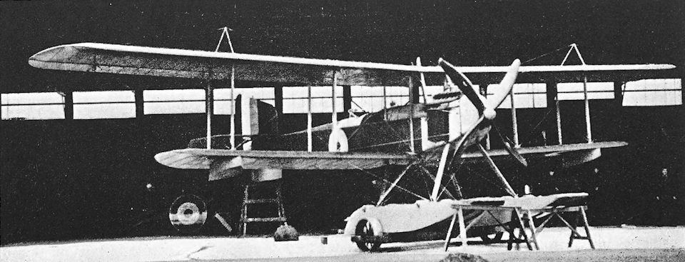
Fairey Campania. The F.16 Campania, with Rolls-Royce Eagle engine.
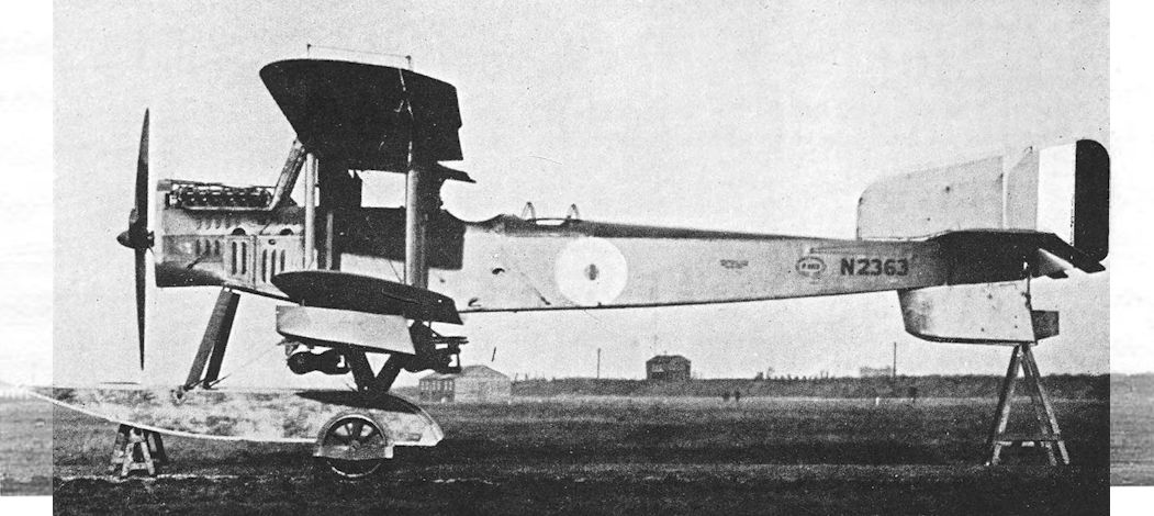
The most powerful of all Campania seaplanes were some of the later F.17s with 345hp Rolls-Royce Eagle VIIIs, as depicted by Fairey-built N2363 at the Isle of Grain on 10 December 1917 with a pair of 112 lb bombs on the centreline beam. The engine demanded increased louvres in the nose panels.
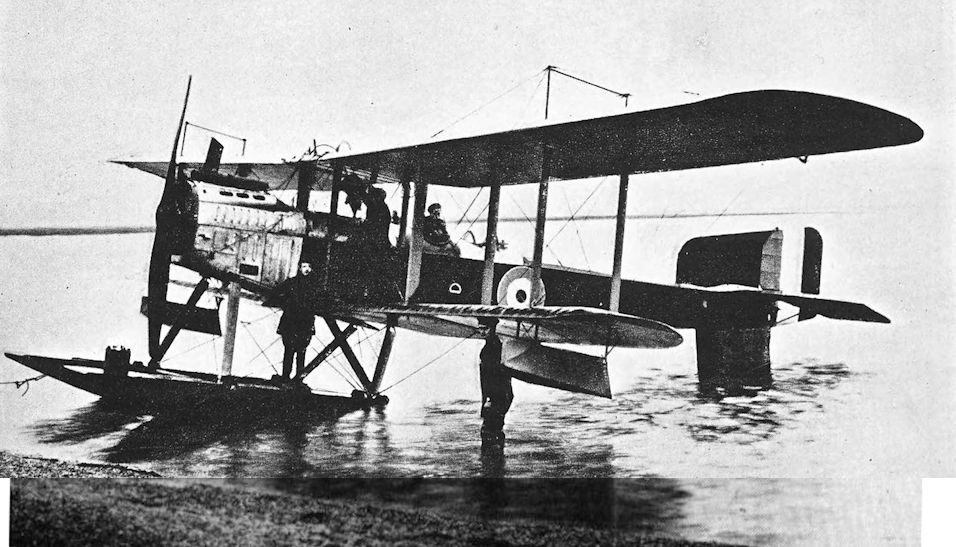
The first of the F.22 Campania variants, N1006 (F.22), seen at Calshot in 1917. The Sunbeam Maori engine had a small nose radiator without shutters.
Fairey F.128 (Fairey III) and Fairey IIIA
THE second of the two experimental floatplanes built by the Fairey company in 1917 was known as the F.128 or N.10: it owed the latter designation to its official serial number. The two machines were built at the same time.
The F.128 was designed as a two-seat patrol seaplane, and had a more powerful engine than the smaller F.127. The 260 h.p. Sunbeam Maori II was installed in the F.128, and there was a radiator block on each side of the engine. The machine had equal-span wings with two-bay bracing; the mainplanes could be folded, and the Fairey Patent Camber Gear was fitted. The fuselage was structurally identical to that of the F.127, and the same tailplane, elevators and rudder were used; the fin of the F.128 was larger than that of the smaller machine.
The F.128 was the patriarch of the line of Fairey Series III aircraft, and actually had the designation Fairey III. After its tests as a seaplane, N.10 underwent modification at the end of 1917 and reappeared as a landplane. A simple vee undercarriage replaced the floats, and the radiator was installed as a single frontal surface immediately behind the airscrew. In this modified form the machine was redesignated Fairey IIIA.
The Fairey IIIA went into production for the R.N.A.S., and was intended for use as a ship-borne two-seater, doubtless to be a replacement for the well-tried but obsolete Sopwith 1 1/2-Strutter. The Armistice prevented the IIIA from showing its paces in action, and it saw no wide-scale service with the R.A.F. Other forms of undercarriage were fitted to the IIIA, among them a plain skid undercarriage which had no wheels but carried a hydrovane after the fashion of the Sopwith Pups and 1 1/2-Strutters with which experiments were carried out at the Isle of Grain.
SPECIFICATION
Manufacturers: The Fairey Aviation Co., Ltd., Hayes, Middlesex.
Power: 260 h.p. Sunbeam Maori II.
Weights (lb) and Performance:
Fairey III Fairey IIIA Fairey IIIA
No. of Trial Report - N.51 M.220
Date of Trial Report September 14th, 1917 December 10th, 1917 July, 1918
Type of airscrew used on trial F.A.4476 F.A.4476 A.B.4475M
Weight empty 2,970 2,532 2,690
Military load 224 224 449
Crew 360 360 360
Fuel and oil 605 578 446
Weight loaded 4,159 3,694 3,945
Maximum speed (m.p.h.) at
sea level 104 109-5 -
6,500 ft 97 107 -
10,000 ft 94-5 104 97
m. s. m. s. m. s.
Climb to
2,000 ft 3 45 - - - -
5,000 ft 9 10 7 05 - -
6,500 ft 12 35 10 00 14 00
10,000 ft 23 30 17 40 26 00
Service ceiling (feet) 14,000 15,000 13,500
Endurance (hours) 41 41 -
Dimensions: Span: 46 ft 2 in. Length: Fairey III, 36 ft; Fairey IIIA, 31 ft. Height: Fairey III, 11 ft 10 in.; Fairey IIIA, 10 ft 8 in. Chord: 5 ft 6 in. Gap: 5 ft 7 in. Stagger: nil. Span of tail: 13 ft.
Areas: Wings: 476 sq ft. Ailerons: each 16-5 sq ft, total 66 sq ft. Tailplane: 34-2 sq ft. Elevators: 34-2 sq ft. Fin: 9-8 sq ft. Rudder: 9-8 sq ft.
Tankage: Petrol: 76 gallons.
Armament: One Lewis machine-gun on Scarff ring-mounting on rear cockpit. Bombs could be carried on external racks.
Production and Allocation: See under Fairey IIIB.
Serial Numbers: Fairey III and IIIA prototype: N.10. Production IIIAs: N.2850-N.2899.
Fairey IIIB
THE Fairey IIIA was followed by the Fairey IIIB, a two-seat seaplane designed for bombing duties: it was regarded as falling within the Admiralty class N.2B. The IIIB had the same fuselage and horizontal tail surfaces as the III and IIIA, but the wing area was increased, larger floats were fitted, and increased vertical tail surfaces used. The upper wing had large extensions, braced from king-posts above the outer interplane struts; the wings could be folded, and the Fairey Patent Camber Gear was fitted.
Ailerons were fitted to the upper wing only. The engine was again the 260 h.p. Sunbeam Maori II, and a frontal radiator similar in shape to that of the IIIA was used.
The Fairey IIIB went into small-scale production, and a few examples had reached some seaplane stations before the Armistice. The type remained in service for a relatively short period, during which its principal duty was the making of mine-spotting patrols.
SPECIFICATION
Manufacturers: The Fairey Aviation Co., Ltd., Hayes, Middlesex. Power: 260 h.p. Sunbeam Maori II.
Dimensions: Span: upper 62 ft 8 15/16 in, lower 44 ft 8 7/16 in. Length: 37 ft 1 in. Height: 14 ft. Chord: 5 ft 6 in.
Gap: 5 ft 7 in. Stagger: nil. Dihedral: 1° 30'. Incidence: 4° 30'. Span of tail: 13 ft.
Areas: Wings: 570 sq ft. Ailerons: each 23 sq ft, total 46 sq ft. Tailplane: 34-2 sq ft. Elevators: 34-2 sq ft. Fin: 12-4 sq ft. Rudder: 12-4 sq ft.
Weights and Performance.: No. of Trial Report: N.M.107. Date of Trial Report: February 21st, 1918. Type of airscrew used on trial: F.A.4441. Weight empty: 3,258 lb. Military load: 681 lb. Crew: 360 lb. Fuel and oil: 593 lb. Weight loaded: 4,892 lb. Maximum speed at 2,000ft: 95m.p.h.; at 6,500ft: 90 m.p.h.; at 10,000 ft: 81 m.p.h. Climb to 2,000 ft: 4 min 10 sec; to 6,500 ft: 17 min 50 sec; to 10,000 ft: 37 min 50 sec. Service ceiling: 10,300 ft. Endurance: 4 1/2 hours.
Tankage: Petrol: 76 gallons.
Armament: One Lewis machine-gun on Scarff ring-mounting on rear cockpit. The total bomb load was apparently about 600 lb, and the bombs were carried on racks suspended under the fuselage.
Service Use: Seaplane station, Westgate.
Production and Allocation: The Fairey Aviation Co. built twenty-five Fairey IIIBs. The official statistics for the aircraft on charge with the R.A.F. on October 31st do not differentiate between the Fairey IIIA and IIIB. On that date, the R.A.F. had a total of seventy machines of both types:. two were at coastal stations, twelve were at other units, thirty-six were at Aircraft Acceptance Parks and with contractors, and twenty were in store.
Serial Numbers: N.2230-N.2259: ordered as IIIBs, but some delivered as IIICs. N.9234.
Fairey IIIC
THE Fairey IIIB was closely followed by the IIIC, which was probably the best British seaplane of its day, but which arrived too late to give any operational service before the Armistice. It had the same fuselage and float undercarriage as all its predecessors, but reverted to the original equal-span wings of the Type III. The tail unit was identical to that of the IIIB.
The IIIC had the magnificent Rolls-Royce Eagle VIII engine, and it was to its power plant that the machine owed its fine performance. Radiators were mounted on each side of the fuselage beside the pilot’s cockpit. The opportunity was taken to fit large fuel tanks, and these gave the IIIC a maximum endurance of six hours. It was essentially a reconnaissance and escort-fighter seaplane, but there can be no doubt that it could have lifted a worthwhile load of bombs had it been required to do so.
It seems probable that the first IIIC, N.2246, was a converted IIIB, and it is equally probable that machines originally ordered as IIIBs were delivered as IIICs. In September, 1918, N.2246 left the Fairey company’s works for the Isle of Grain experimental station, where it underwent its official trials. Apparently it was despatched in such haste that no airscrew was sent with it, for consideration was given to the fitting of a four-bladed airscrew which had belonged to a D.H.4. The official tests were ultimately completed with a suitable airscrew.
Production machines were just beginning to appear in November, 1918, and in that month Great Yarmouth air station received its first IIIC. The IIIC saw operational service, however, for it was one of the types which formed the equipment of the North Russian Expeditionary Force in 1919.
The Fairey IIIC survived in service for a short time, but it was replaced by the more powerful IIID after a year or two. In the years immediately after the war, experimental modifications of the type appeared: one had a ski undercarriage, another had amphibian landing gear.
SPECIFICATION
Manufacturers: The Fairey Aviation Co., Ltd., Hayes, Middlesex.
Power: 375 h.p. Rolls-Royce Eagle VIII.
Dimensions: Span: 46 ft 1 1/4 in. Length: 36 ft. Height: 12 ft 1 3/4 in. Chord: 5 ft 6 in. Gap: 5 ft 3 in. Stagger: nil. Dihedral: 1° 04'. Incidence: 4° 30' at centre-section, 4° 22' 30" at inner struts, 4° 15' at outer struts. Span of tail: 13 ft.
Areas: Wings: 476 sq ft. Ailerons: each 16-5 sq ft, total 66 sq ft. Tailplane: 34-2 sq ft. Elevators: 34-2 sq ft. Fin: 12-4 sq ft. Rudder: 12-4 sq ft.
Weights (lb) and Performance:
Flight condition Light load Medium load Normal load Overload
No. of Trial Report N.M.238A N.M.238 N.M.238 N.M.247
Date of Trial Report December 9th, 1918 October 26th, 1918 October 24th, 1918 March, 1919
Type of airscrew used on trial F.A.6194 F.A.6194 F.A.6194 F.A.6952
Weight empty 3,392 3,392 3,392 3,549
Military load 170 170 170 247
Crew 360 360 360 360
Fuel and oil 350 678 878 883
Weight loaded 4,272 4,600 4,800 5,039
Maximum speed (m.p.h.) at
2,000 ft 110-5 - 110-5 101
6,500 ft 107 105 107 95-5
10,000 ft 103-5 101 102'5 -
m. s. m. s. m. s. m. s.
Climb to
2,000 ft 2 20 2 10 2 20 3 40
6,500 ft 8 00 8 30 9 30 16 30
10,000 ft 14 15 17 30 18 00 44 00
Service ceiling (feet) 17,000 15,400 15,000 9,100
Endurance (hours) 2 4 5 1/2 5
Tankage: Petrol: 120 gallons.
Armament: One fixed forward-firing Vickers machine-gun, synchronised to fire through the airscrew; one Lewis machine-gun on Scarff ring-mounting on rear cockpit; 250 rounds for the Vickers gun, three 97-round drums for the Lewis. Bombs could be carried on racks under the fuselage.
Service Use: No. 229 Squadron, Great Yarmouth, and at Felixstowe. Russia: aircraft carrier H.M.S. Pegasus with North Russian Expeditionary Force at Archangel.
Serial Numbers: N.2246 and N.2255; between and about N.9235 and N.9255.

Fairey F.128, N.10

Fairey F.128, N.10, at the Isle of Grain.

Fairey IIIA. The landplane conversion of N.10.

Fairey IIIB.

The first Fairey IIIC, N2246, was a factory conversion of a IIIB.
Felixstowe F.1
JOHN CYRIL PORTE was a Lieutenant in the Royal Navy when, in 1909, he began to experiment with a glider on Portsdown Hill, near Portsmouth. Two years later he was invalided out of the Service with tuberculosis. His disability did nothing to diminish his enthusiasm for flying; rather it seemed to increase it, and by 1912 he was appointed technical director and designer of the British Deperdussin Company. He had learned to fly on a Deperdussin monoplane at Rheims, and his Aviator’s Certificate, dated July 28th, 1911, was No. 548 of the Aero Club de France.
From then until the Deperdussin company’s flying school at Hendon was forced to close down in August, 1913, Porte became well-known as an excellent pilot. Later that year he became associated with Captain Ernest C. Bass, who, on behalf of White & Thompson, Ltd., acquired the British rights for the products of the Curtiss Aeroplane Company of Hammondsport, New York, U.S.A. In October, 1913, Glenn Curtiss personally delivered one of his latest flying boats to Bass at Brighton: the machine was housed in a canvas hangar which had been erected by Magnus Volk. At Brighton, the Curtiss flying boat was flown by J. D. Cooper, and his passengers included E. C. Gordon England and John Porte.
Porte was so impressed by the flying boat and its potentialities that he resigned his position as test pilot of the White & Thompson Co., Ltd., in 1914 and went to join Curtiss at Hammondsport. Curtiss had been commissioned by Rodman Wanamaker to design a flying boat capable of flying across the Atlantic, with the intention of competing for the prize of £10,000 which had been offered by the Daily Mail in 1913 for the first trans-Atlantic flight.
The flying boat was named America and was the precursor of the Curtiss H.4 type which was used by the R.N.A.S. during the war. The original America had a wing span of 72 feet, and was powered by two 90 h.p. Curtiss engines; there was tankage for 300 gallons of petrol and 25 gallons of oil. An enclosed cabin was provided for the crew of two. Porte was to have been one of those two, but just when America was completed the war began in Europe. He returned to England at once and rejoined the Navy: he was at once made a Squadron Commander in the R.N.A.S. At his instigation the Admiralty bought two flying boats of the America type which, when delivered, were given the official serial numbers 950 and 951. These boats were delivered by November, 1914, and were sent to Felixstowe for trials. The results were regarded as promising and a few more Curtiss flying boats were ordered; after further trials an order was placed in March, 1915, for fifty machines of similar design but with more powerful engines. These aircraft were delivered in the second half of 1915 and were officially designated Curtiss H.4.
In September of that year, Squadron Commander Porte was given the command of the R.N.A.S. Station at Felixstowe. By that time he had flown the America boats operationally and was aware of their shortcomings. He had therefore set about the task of modifying and improving them in an endeavour to produce a truly seaworthy and usable flying boat. In this work he was ably assisted by his Chief Technical Officer, Lieutenant J. D. Rennie.
The first experiments had been carried out early in 1915, using No. 950, one of the original America boats purchased by the Admiralty. This had a 30-foot hull, which was modified by the addition of wide longitudinal fins which ran from near the bows to the single step, which was under the C.G. The original lifting tail was given negative camber to improve longitudinal stability.
This hull was not too satisfactory in rough weather, and a second was constructed for the Curtiss flying boat No. 1230. This hull had longer, narrower fins which ran farther aft, for the step was under the rear spar of the lower mainplane; the tail portion of the hull was rounded and had a concave curve on its underside. This caused excessive suction, and take-off with this hull was very difficult. Overall length of No. 1230’s hull was 32 feet 7 1/2 inches, but a different method of construction enabled it to be made 300 lb lighter than that of No. 950. Its lightness was obtained at the expense of strength, however, and it failed after several landings.
A third hull, 32 feet 4 inches long, was made for the Curtiss H.4 No. 3545. The tail portion was two feet longer than that of No. 1230, and the hull resembled No. 950 in a general way. The forebody was slightly longer and the longitudinal fins were wider, whilst the underside of the tail portion was flat.
The fourth experimental hull was fitted to the Curtiss H.4 No. 3569, and was 32 feet 2 inches long. It was fundamentally similar to No. 3545, but had a much more pronounced vee bottom. The available power (presumably a nominal 200 h.p.) was insufficient to lift the flying boat off the water, so a step was added five feet aft of the C.G.; the machine then took off at a loaded weight of 4,200 lb. Landing was easy and comfortable, thanks to the vee bottom, but the position of the step so far behind the C.G. demanded considerable physical exertion by the pilot at take-off. To relieve the pilot, the step was moved three feet forward.
The fifth hull differed from all its predecessors, both in construction and appearance. It was a completely new design and was in every sense the prototype of all the succeeding “F” boats. The machine to which it was fitted was No. 3580. The hull was named Porte I, and subsequently the aircraft was designated F. 1. The basic structure of the hull differed little from that of contemporary landplanes, for it was a cross-braced wooden box girder, to which a vee planing bottom and longitudinal fins had been added. This hull was 36 feet 2 inches from stem to stern, and originally had a single step below the rear spar; the bows were more fully flared than those of earlier hulls. The aircraft was powered by two 150 h.p. Hispano- Suiza engines.
Tail drag made take-off difficult, so a second step was added 7 feet 6 inches from the stern; and finally a third step was fitted between the first two. This hull proved itself superior in every way to its predecessors: the improved bow design prevented the shipping of water, and take-off and landing performance was excellent. The cockpit was open, whereas all the preceding experimental hulls had had enclosed cabins.
The F. 1 had the wings and tail unit of a normal Curtiss H.4 flying boat, but the Hispano-Suiza engines were a special installation, for the standard R.N.A.S. machines had two 100 h.p. Anzani radial engines.
SPECIFICATION
Manufacturers: Seaplane Experimental Station, Felixstowe.
Power: Two 150 h.p. Hispano-Suiza.
Dimensions: Span: upper 72 ft, lower 46 ft. Length of hull only: 36 ft 2 in. Chord: 7 ft. Gap: 7 ft 6 in.
Serial Number: 3580.

The “Incidence Boat”, No. 3546.

One of Squadron Commander Porte’s experimental hulls: the aircraft had the wings of a Curtiss H.4 and two Clerget engines; it was known as “The Incidence Boat”.
Felixstowe F.2A and F.2C
AFTER the success which had been achieved with the F.1, Squadron Commander Porte extended his A experiments to larger hulls. He began work with No. 8650, the first Curtiss H.12 flying boat to be delivered to the R.N.A.S.
The H.12 was generally similar in design to the H.4, but was considerably larger. On its appearance in service it was named the Large America, whereafter the H.4 was known as the Small America. As delivered, the H.12 had two 160 h.p. Curtiss engines, but when Porte began his experiments with No. 8650, these proved to be insufficiently powerful to get the boat off the water at a weight of 8,700 lb. The Curtiss engines were replaced by two 250 h.p. Rolls-Royce engines. Take-off was then accomplished, but with difficulty, owing to lack of buoyancy forward. The hull of the H.12 was weak structurally, yet these Large Americas did some excellent work when powered by two Rolls-Royce Eagle engines of later marks.
It was obvious that the F.1 hull was superior to that of the Curtiss H.12, so it was decided to build a hull similar to the Porte I but large enough to take the wings of the Large America. The new hull was known as the Porte II, and the aircraft to which it was fitted was designated F.2. It was the prototype of the line of successful F-boats, which gave such distinguished service up to and beyond the Armistice.
The F.2’s hull was almost identical to that of the F.1 in outline but was larger: it was 42 feet 2 inches long, and its maximum beam was 10 feet. It had only two steps, and these were applied outside the skin of the hull, as had been done on the F.1. The forward step was directly under the rear spar of the wings, and the rear step was 6 feet 5 inches farther aft. Structurally the hull was basically a cross-braced box girder, as opposed to the original Curtiss boat-built hull. Forward of the rear spar of the centre-section the sides of the hull were braced as N-girders; elsewhere the cross-bracing was by means of wires or tie-rods. The spars of the lower centre-section were integral parts of the hull box girder. The bottom longerons were spaced by solid mahogany members known as floors: these floors were inverted triangles whose downwards-pointing apices formed the ridge of the keel. Athwartships they were unbroken, but for two- thirds of their depth they were notched out to fit over the solid keelson, which was correspondingly notched out for one-third of its depth and ran from bows to sternpost as a continuous structural member.
As on the F.1, hull, the side fins were built on to the outside of the basic hull structure. To give adequate support to the planking between floors, intermediate timbers of rock elm ran from chine to chine. The double-diagonal planking consisted of an inner skin of 1/8-inch cedar and an outer of 3/16-inch mahogany separated by a layer of varnished fabric. This planking was applied to the hull bottom, whilst the fin tops and the hull sides were planked with three-ply; abaft the rear spar the hull sides were fabric-covered and had a solid mahogany washboard along the lower longerons. The top of the hull was also fabric-covered, with the exception of the portion in front of the cockpit, which was planked with plywood. A semi-enclosed cabin was provided for the crew. The shape of the hull was such that the tail was carried high: this served not only to keep the tailplane out of spray when taxying, but also to give the waist gunners a good field of fire towards the rear.
The wings were similar to those of the Curtiss H.12. The upper mainplanes had long extensions, the landing wires for which ran from rectangular pylons above the outermost interplane struts: these pylons were faired over with fabric, but the resulting vertical surfaces had no designed aerodynamic function. There were three bays of struts outboard of the engines.
The Porte II hull proved to be an excellent design, and the F.2 was strong and seaworthy. One of the great advantages of the Porte design of hull was its structural simplicity, which enabled it to be made by firms which had no experience of boat-building. The type was placed in production with several contractors in 1917, but delays occurred: an official decision to change from the original 23-inch gun-ring to one of 20-inch diameter necessitated structural modifications and held up. production.
The production machines had two 360 h.p. Rolls-Royce Eagle VIII engines, and embodied other minor modifications. They were designated F.2A. Deliveries began to be made at the end of 1917, and from early 1918 until the Armistice the type was in use at almost every flying-boat station of the R.N.A.S. This widespread use gave some trouble with the early F.2A hulls, for the machine had been designed to operate from sheltered harbours, and exposure to unfavourable sea conditions led to deterioration of the hull. The original 5-inch planks on the hull bottom warped, the plywood on the fin tops and sides opened up, and the fabric rotted. Narrower planks were therefore fitted, double-diagonal planking of mahogany and cedar was applied to the fin tops, and the sides were either given single planking with fabric covering or were completely planked with Consuta, the special material invented by S. E. Saunders, Ltd. It consisted of plywood sewn with copper into large sheets. Other structural modifications had to be made to meet the rigours of operational service.
The estimated life of the F.2A under mooring conditions was six to eight months, but where hangar and slipway facilities were available the boats were taken ashore on wheeled trolleys specially made to conform to the shape of the hull bottom. Manhandling these relatively fragile wooden hulls could be a tricky business, and the beaching crew had to be both numerous and skilful. A vivid account of a launching, take-off, flight, and landing and beaching of an F.2A is to be found in pages 352-357 of The Story of a North Sea Air Station, by C. F. Snowden Gamble.
The flying boats of Felixstowe air station are probably best remembered for their connexion with the famous “Spider Web” patrol. This patrol was flown as an octagonal figure centred on the North Hinder Light Vessel. Sixty nautical miles across, it enabled some 4,000 square miles of sea to be systematically searched: this area lay across the most possible tracks of enemy submarines. The five flying boats which began to operate the Spider Web patrol on April 13th, 1917, made twenty-seven patrols before the month was out, sighted eight U-boats and bombed three of them, and had one engagement with enemy destroyers.
It was into action of this tradition that the F-boats came. Unfortunately, the shortage of Rolls-Royce engines severely hampered the production of the big flying boats. In May, 1917, when the requirements of aircraft for 1918 were under consideration, it was estimated that 180 flying boats of the Large America type would be needed. The Government’s decision to double the size of the British air services, taken in July, 1917, increased that number to 426. In view of the fact that the average life of a flying boat was six months, the total requirements for the full year of 1918 amounted to 852 flying boats. This figure was impossible of achievement, but the net requirements were reduced to 234 upon the U.S. Navy Department’s agreement to equip five seaplane stations and upon the decision to build at Malta the sixty boats required for the Mediterranean area.
By March, 1918, 161 F.2As had been ordered, but only ten were in service. The required total of 234 was to consist of both F.2As and the later F.3s, but it was never realised. A review of the production of Rolls-Royce engines showed that sufficient Eagles would be available to equip only 170 Large America boats by the end of May, 1918. Even that estimate proved to be over-optimistic, for only 104 F-boats had been delivered by that date.
All the big twin-engined Porte-designed flying boats were known as Large Americas, and it is difficult to distinguish one type from another or from the original Curtiss H.12 in the official history. The F.2A was the best-known boat of the series, partly because it was a better machine than the F.3 and partly because the F.5 arrived too late to see service on a large scale.
The R.N.A.S. air station at Great Yarmouth received the first of its F.2As early in February, 1918, but trouble was experienced with the fuel system. The main fuel tanks were in the hull, and petrol was pumped to a gravity tank in the centre-section by means of wind-driven pumps; the carburettors were fed from the gravity tank. The total length of piping in the system was therefore considerable, and most of the faults occurred in the fuel pipes. On February 5th, 1918, the first patrol to be attempted by a Great Yarmouth F.2A was balked by a partial choke in a petrol pipe, and eleven days later the same machine, N.4511, was forced down one hour out from base with the gravity tank filter clogged. The crew were picked up by H.M.S. Glowworm, and owed their rescue to a home-made precursor of the dinghy radio developed in World War II. Leading Mechanic Walker had been experimenting at Yarmouth with a 5-foot linen box kite carrying an aerial, and on this occasion he had his apparatus with him on board N.4511. From its signals the position of the flying boat was fixed, and H.M.S. Glowworm found it only eight miles down wind from the position she was given.
The F-boats from Yarmouth and Felixstowe had many brushes with the Brandenburg W.12 and W.29 seaplane fighters from the enemy seaplane stations at Borkum, Norderney and Zeebrugge. The boats usually gave as good as they got, for their heavy defensive armament and the determination of their crews made up for their lack of speed and manoeuvrability.
On June 4th, 1918, five flying boats led by Captain R. Leckie set out for the Haaks Light Vessel with the one intention of seeking out and fighting enemy seaplanes. The force consisted of four F.2As and one Curtiss H.12: the F.2As were N.4295 and N.4298 from Great Yarmouth, and N.4302 and N.4533 from Felixstowe; whilst the H.12 was 8689 from Felixstowe. But even before the enemy were sighted the petrol feed pipe to one of the engines of N.4533 broke, and the F.2A was forced down. Its pilot (Captain Dickey) could do no more than taxi to Holland, where he beached and burned the machine. The H.12 had set off in hot pursuit of some German machines which had attacked and were intent on harassing the limping N.4533, and the three remaining F.2As were later engaged by a mixed force of fourteen enemy seaplanes. The F.2As fought an action which must rank as a veritable Jutland of the skies, and Leckie led the little force with magnificent audacity. N.4302 was compelled to go down with a broken petrol pipe, and Captain Hodson flew N.4289 on one engine whilst the other was repaired during the combat. The engineer of N.4302, Private Reid, made a temporary repair which enabled the boat to return to Great Yarmouth, despite a damaged wing-tip float.
At 7.10 p.m. the three F.2As alighted in Great Yarmouth Roads after being airborne just over six hours and fighting one of the greatest air battles of the war, for the enemy lost six seaplanes. But Leckie’s report included the acrid comment: “It is again pointed out that these operations were robbed of complete success entirely through faulty petrol pipes.... It is obvious that our greatest foes are not the enemy, but our own petrol pipes.”
This action was largely responsible for the general adoption of the gaudy “dazzle-painting” of many F-boats. The F.2A flown by Captain Hodson, N.4289, “was terrible in appearance, painted post-box red, with yellow lightning marks running diagonally across her ... he fondly hoped that this would put the wind up the Hun.” Whether it did that or not is not known, but it left Hodson’s comrades in no doubt about his aircraft’s identity. The first object of the dazzle-painting was to identify the pilot of any particular flying boat, so, at Great Yarmouth, the choice of scheme was left to individual pilots. This produced some bizarre combinations of checks, stripes and zig-zags in bright colours. Felixstowe had a more or less standard (but no less striking) colour scheme for its boats.
One of the Felixstowe F.2As was experimentally fitted with two “howdah” gun positions on the upper wing. Each contained a gunner and twin Lewis guns on a Scarff ring. The bow gunner also had twin Lewis guns, and it seems probable that the machine was intended to act as an escort fighter for the patrolling F.2As. The experiment was not a success, however, and the idea was abandoned.
On May 10th, 1918, an F.2A from Killingholme, flown by Captains T. C. Pattinson and A. H. Munday, engaged the Zeppelin L.62 at 8,000 feet over the Heligoland minefields. Captain Munday opened fire from the bow cockpit and Sergeant H. R. Stubbington, the engineer, also brought his Lewis gun to bear on the target. Many hits appeared to be scored, but the flying boat broke an oil feed pipe and had to alight on the sea. The Zeppelin made off due east, losing height and emitting smoke, and soon afterwards blew up and fell in flames.
A most ambitious scheme in which F.2A flying boats were concerned was the use of lighters, towed by destroyers, as a means of increasing the radius of action of the flying boats. The idea had first been proposed by Squadron Commander Porte in September, 1916. His original design was for a channel-shaped lighter which could be submerged by the flooding of tanks; after the flying boat had been floated into position, the water was blown out of the tanks by compressed air. This raised the flying boat clear of the water, and the lighter was free for towing.
Orders for four lighters were placed in January, 1917, and the first was successfully tested in the following June. As actually built, the lighter was made to submerge only at the stern and the flying boat was warped aboard. Towing trials promised well, and in September, 1917, a lighter with a flying boat aboard was towed at speeds up to 32 knots. Twenty-five lighters were ordered immediately, a number which was subsequently increased to fifty. The first was delivered in May, 1918, and fifty-one had been delivered by the time of the Armistice.
One of the chief objects of the use of lighter-borne flying boats was to carry out bombing attacks on the German naval bases in the North Sea, but their first use was to provide advanced take-off facilities for distant reconnaissances in the Heligoland Bight. The first operation of this kind took place on March 19th, 1918, apparently using three of the prototype lighters. At 5.30 a.m. three destroyers towed flying boats to a point off the German coast, and the three boats were airborne by 7 a.m. During their patrol they shot down one of two enemy seaplanes which attacked them, and flew back to their base direct. Next day the operation was successfully repeated, and the towed flying boats were used on several later occasions in 1918. The original intention of using the lighter-borne flying boats to bomb enemy naval bases was abandoned in July, 1918, by which time sufficient progress had been made with long-range bomber landplanes to bring the targets within their radius of action.
The F.2A remained in service right up to the time of the Armistice. Because its performance was better than that of the F.3 it was chiefly used from stations which covered the sea areas where fighting, anti-Zeppelin work and reconnaissance predominated. The F.3 was used at stations responsible for antisubmarine patrols, for which duty its longer range made it more suitable.
Many modifications were made to production F.2As: some were incorporated on the production lines; others were made locally at seaplane stations to meet the personal tastes of crews. One of the most noticeable changes Was the absence of the cabin top over the pilots’ cockpits on later F.2As: its removal improved their view considerably, particularly towards the rear, and added a few knots to the speed. Such F.2As began to appear about September, 1918. They also had the sides of the hull planked overall with mahogany or, in the case of the Saunders-built machines, Consuta.
A further significant modification, incorporated at this time, was the fitting of constant-chord horn-balanced ailerons similar to those of the F.5. This helped to relieve some of the considerable physical strain imposed upon the pilot; protracted patrols could be exhausting in a heavy aircraft which had no balanced controls of any kind. Several pilots went so far as to fit modified flight controls of their own design.
It is doubtful whether an F.2B variant was ever built, but the designation has been applied to the open-cockpit version of the F.2A. A modified type known as the F.2C was, however, built and flown. It had a lightened hull with modified steps and new contours for the forebody. The bow gunner’s cockpit was farther back from the bows than on the F.2A, and the cockpit for the pilots was open. A deep top-decking was fitted to the hull, and there were no waist hatches behind the wings.
Although the F.2C did not go into production, it was used operationally by the War Flight at Felixstowe seaplane station. On July 24th, 1917, Felixstowe sent out a patrol of five flying boats, the greatest number despatched together up to that time. The patrol was led by Wing-Commander Porte himself in the F.2C. Near the North Hinder Light Vessel, the periscope of a U-boat was sighted. Three of the flying boats dropped a total of five 230-lb bombs on the submarine and sank it: two of the bombs were, dropped by the F.2C, which thus played a leading part in the destruction of the enemy submarine U.C.1.
The F.2C was fitted with an experimental bomb-dropping gear which was actuated by compressed air instead of the simple Bowden cable mechanism which was used on the other F-boats. The compressed air gear was elaborate and not wholly reliable: at least one enemy submarine owed its escape to the gear’s defection one day late in September, 1917, when the F.2C was being flown by Squadron Commander T. D. Hallam, D.S.C. He attacked a surfaced U-boat, but his bombs failed to leave the racks.
SPECIFICATION
Manufacturing Contractors: The Aircraft Manufacturing Co., Ltd., Hendon, London, N.W.; hulls made by May, Harden & May, Southampton Water. S. E. Saunders, Ltd., East Cowes, Isle of Wight (built 100 F.2As). The Norman Thompson Flight Co., Bognor Regis (F.aAs built at the Littlehampton works; production may have consisted of hulls only).
Power: F.2A: two 345 h.p. Rolls-Royce Eagle VIII. F.2C: two 275 h.p. Rolls-Royce Mk. II (322 h.p. Eagle VI).
Dimensions: Span: upper (F.2A) 95 ft 7 1/2in.; (F.2C) 95 ft; lower (F.2A) 68 ft 5 in. Length: F.2A, 46 ft 3 in.; F.2C, 46 ft. Height: 17 ft 6 in. Chord: 7 ft 1 in. Gap: 7 ft 1 in. Stagger: nil. Dihedral: 1°. Incidence: 4° 15'.
Areas: Wings: F.2A, 1,133 sq ft. F.2C, 1,136 sq ft.
Tankage: F.2C: petrol, 220 gallons; oil, 16 gallons.
Armament: Four Lewis machine-guns were usually carried: one was on a Scarff ring-mounting on the nose cockpit; another was mounted in the upper rear cockpit behind the wings; and there was one in each waist position. Sometimes a double-yoked pair of Lewis guns were carried in the bow and upper rear cockpits, and frequently an additional Lewis was mounted on top of the pilots’ cockpit canopy. Two 230-lb bombs were carried in racks under the lower mainplane.
One experimental F.2A had a “howdah” gunner’s cockpit let into each upper mainplane above the first pair of interplane struts outboard of the engines. Each gunner had a pair of double-yoked Lewis guns on a Scarff ring-mounting.
F.2C: twin Lewis guns on Scarff ring-mounting on bow cockpit. Two 230-lb bombs under each lower wing.
Service Use: Flown from R.N.A.S. seaplane stations at Felixstowe, Great Yarmouth, Killingholme, Calshot, Dundee, Scapa Flow and Tresco, Scilly Isles (later No. 234 Squadron); No. 230 Squadron, R.A.F.
Distribution: On October 31st, 1918, the R.A.F. had fifty-three F.2As on charge. All were at seaplane stations in the United Kingdom; none were overseas.
Serial Numbers: N.4080-N.4099: ordered as F.2As from S. E. Saunders; some delivered as F.5s. N.4280-N.4309: ordered as F.2As from S. E. Saunders. N.4430-N.4479: ordered as F.2As from S. E. Saunders; some delivered as F.5s. N.4480-N.4504: ordered as F.2As from the Aircraft Manufacturing Co. (May, Harden & May); some delivered as F.5s. N.4510-N.4519: built by the Aircraft Manufacturing Co. (May, Harden & May). It was at one time intended to fit Sunbeam engines to these ten F.2As. N.4530-N.4554: built by the Aircraft Manufacturing Co. (May, Harden & May). Between N.4560 and N.4568 were F.2As. It is believed that N.4584 was an F.2A. N.65: the F.2C.
Weights (lb) and Performance:
Type F.2A F.2C
No. of Trial Report N.M. 125 -
Date of Trial Report March, 1918 June 23rd, 1917
Type of airscrew used on trial A.B.665 A.B.665
Weight empty 7,549 6,768
Military load 585 402
Crew 720 720
Fuel and oil 2,124 2,350
Weight loaded 10,978 10,240
Maximum speed (m.p.h.) at
2,000 ft 95-5 98
6,500 ft 88-5 94
10,000 ft 805 91
m. s. m. s.
Climb to
2,000 ft 3 50 4 50
6,500 ft 16 40 18 20
10,000 ft 39 30 38 00
Service ceiling (feet) 9,600 10,300
Endurance (hours) 6 -
Notes on Individual Machines: F.2As used at Great Yarmouth: N.4283, N.4289, N.4295, N.4298, N.4303, N.4305,
N.4511, N.4512, N.4549, N.4550. F.2As used at Felixstowe: N.4302 and N.4533. F.2As used at Killingholme: N.4287, N.4290, N.4291, N.4516. N.4545 had the later open cockpit for the pilots.
Costs:
F.2A flying boat including hull and trolley, but without engines, instruments and guns £6,738 0s.
Rolls-Royce Eagle VIII engine, each £1,622 10s.
Felixstowe F.3
ALTHOUGH the F.3 was almost indistinguishable from the F.2A and was produced in larger numbers, it was not so well-liked as the earlier design. The F.3 was a rather larger flying boat and could carry double the load of bombs on the same power, but it did not handle so well as the F.2A.
The hull was very similar to that of the F.2A, but was about three feet longer. The “fuselage-type” construction was again employed, but an unfortunate change was made in the design of the floors: instead of being continuous athwartships, as on the F.2A, they were made in two halves, each of which was rebated into the keelson on either side. This produced an unsatisfactory structure, and the planking sprang readily along the garboard strake, with subsequent leakage. Intermediate timbers were later introduced to support the planking, but the F.3 hull was never so satisfactory as that of the F.2A. The hull was planked in the same way as that of the F.2A. As on the earlier aircraft, the birch three-ply covering of the fin tops was later replaced by double-diagonal planking.
The wings were of greater span and chord, but the interplane bracing was of the same configuration as that of the F.2A. The leading edge of the upper wing was slightly recessed immediately behind the airscrews. On the prototype F.3 a vertical surface was fitted between the first pair of interplane struts outboard of the engines, but this feature was not reproduced on later machines.
The prototype, N.64, was tested with two 320 h.p. Sunbeam Cossack engines, but production F.3s had two Rolls-Royce Eagle VIIIs which drove opposite-handed airscrews. The tail-unit was indistinguishable from that of the F.2A; The wing-tip floats were the same as those of the earlier type, and therefore did not quite reach the trailing edge of the lower wing. It appears that N.64 was used operationally, for an F.3 was reported in use with Felixstowe’s War Flight as early as July, 1917, long before production F.3s were available. (This first F.3 survived until May 15th, 1918, when it was written off at Felixstowe.)
The F.3 was ordered in such quantities that it seems that it was preferred to the F.2A, possibly because of its larger bomb load. The allocations of serial numbers for batches of F.2As and F.3s (though by no means a reliable guide) seem to indicate that orders for the two types of flying boat were placed simultaneously. Production was begun in 1917 by several contractors.
There are indications that Porte and his colleagues had misgivings about the official decision to produce the F.3 in such quantities; and indeed the decision’s effect was to reach beyond the type F.3 itself, for it later affected the F.5 also. By March, 1918, orders for F.3s totalled 263; only one was in service at that time.
The shortage of Rolls-Royce engines had an adverse effect upon the production of F.3s just as it had held up the F.2A. It had been known as early as the spring of 1917 that the demands of home seaplane stations would absorb all the flying boats that could be built in Britain: this situation is analysed in some detail in the history of the F.2A. In the Mediterranean there was, however, a clamant need for flying boats for anti-submarine patrols, and it was therefore decided to build F.3s at Malta. Local labour was employed. The men, who were expert boat-builders, had no difficulty in making the simple Porte-type hulls, and Maltese women were employed as fabric workers under the supervision of Lady Methuen, the wife of the Governor of the island. The first Maltese-built F.3 was completed in November, 1917, and seventeen more were built there during the following twelve months.
Because of its greater range and inferior performance relative to the F.2A, the F.3 was used from seaplane stations responsible for anti-submarine patrols rather than fighting. The type had the added distinction of serving in the Mediterranean; one accompanied the Allied fleet in its attack upon the Albanian port of Durazzo on October 2nd, 1918.
The flight condition of the F.3 depended upon the nature of its duty and upon the duration of the flight. It was loaded to four different flight conditions, as the performance tables show.
In the experimental field, an F.3 was used to test servo-operated controls; and another was fitted with the automatic landing device invented by Major A. Q. Cooper. A long arm, connected to the pilot’s control column by an elastic linkage, was allowed to trail below the aircraft in flight; on striking the water the arm moved the control column backwards and automatically rounded-out the boat’s approach. Success was not achieved at once, but fully automatic landings were ultimately accomplished.
The prototype F.3 had flown as early as February, 1917, and the production machines were contemporary with the production F.2As. After the Armistice, the F.3 was withdrawn in favour of the F.2A and the F.5, and was finally declared obsolete in September, 1921.
SPECIFICATION
Manufacturing Contractors: Dick, Kerr & Co., Ltd., Preston; The Phoenix Dynamo Manufacturing Co., Ltd., Bradford; Short Brothers, Ltd., Rochester; Dockyard Constructional Unit, Malta.
Power: Prototype: two 320 h.p. Sunbeam Cossack. Production: two 345 h.p. Rolls-Royce Eagle VIII.
Dimensions: Span: upper 102 ft, lower 74 ft 2 in. Length: prototype 45 ft, production 49 ft 2 in. Height: prototype 18 ft, production 18 ft 8 in. Chord: 8 ft. Gap: 8ft 6in. Stagger: nil. Dihedral: 1° 30'. Incidence: 4°. Span of tail: 22 ft. Airscrew diameter (Eagles): 10 ft.
Areas: Wings: 1,432 sq ft. Ailerons: each 65 sq ft, total 130 sq ft. Tailplane: 118 sq ft. Elevators: 67 sq ft. Fin: 37-2 sq ft. Rudder: 30-3 sq ft.
Tankage: Petrol, maximum: 400 gallons. Oil: 15 gallons.
Armament: One Lewis machine-gun on rotatable mounting on bow cockpit; one on cockpit aft of wings; and one in each waist position. Four 230-lb bombs were carried in racks under the lower wings.
Service Use: Used from seaplane stations at Felixstowe, Cattewater, Houton Bay, Scilly Isles, and flown in the Mediterranean, probably from Taranto.
Distribution: On October 31st, 1918, the R.A.F. had ninety-six F.3 flying boats on charge. Eighteen were attached to the Grand Fleet for patrol duties; twenty-six were at various seaplane stations and three others were at non-operational stations in the United Kingdom; thirteen were in the Mediterranean; one was at an Aeroplane Repair Depot; eighteen were with contractors; and seventeen were in store.
Weights (lb) and Performance:
Engines Two 320 h.p. Sunbeam Cossack Two 345 h.p. Rolls-Royce Eagle VIII
Flight condition - Light load Medium load Normal load Overload
No. of Trial Report - N.M.155 N.M.155 N.M.155 N.M.155
Date of Trial Report February 9th, 1917 and April 19th, 1917 April 26th, 1918 April 26th, 1918 April 29th, 1918 May 7 th, 1918
Type of airscrew used on trial A.B.586 A.B.665 A.B.665 A.B.665 A.B.665
Weight empty 8,270 7,958 7,958 7,958 7,958
Military load Nil 238 1,317 1,461 1,461
Crew 900 720 720 720 720
Fuel and oil 2,455 836 2,089 2,096 3,142
Weight loaded 11,625 9,752 11,084 12,235 13,281
Maximum speed (m.p.h.) at
400 ft 88-5 - - - -
2,000 ft - 93 92,5 91 90
6,500 ft - 91-5 - 86 87
10,000 ft - 87-5 - - -
m. s. m. s.
Climb to
2,000 ft 3 00 3 10 4 00 5 25 7 50
6,500 ft 27 00 12 55 18 00 24 00 41 00
10,000 ft 60 00 24 50 41 30 - -
Service ceiling (feet) - 12,500 10,000 8,000 6,000
Endurance (hours) - 2 1/4 6 6 9 1/2
Serial Numbers: N.64: prototype F.3. N.4000-N.4049: ordered as F.3s from Short Bros., some delivered as F.5s. N.4100-N.4159: built by Dick, Kerr & Go. N.4160-N.4179: built by Phoenix Dynamo Manufacturing Co. N.4180-N.4229: ordered as F.3s from Phoenix Dynamo Manufacturing Co.; some delivered as F.5s. N.4230- N.4279: built by Dick, Kerr & Co. N.4310-N.4321: built at Malta Dockyard. N.4370: built at Malta Dockyard. N.4400-N.4429: built by Phoenix Dynamo Manufacturing Co.
Notes on Individual Machines: Used at Tresco, Scilly Isles (later No. 234 Squadron): N.4000, N.4001, N.4002, N.4234, N.4238, N.4240, N.4241, N.4415.
Felixstowe F.5
THE designation F.5 was applied to two different flying boats. The first was the boat whose serial number was N.90, and was John Porte’s last Felixstowe biplane design.
The hull was structurally similar to Porte’s earlier hulls, but was rather deeper and had no cabin enclosure for the crew. The sides abaft the mainplanes were fabric-covered and had the usual mahogany washboard along the entire length of their lower edges. The F.5 hull was regarded as the best of the Porte hulls, with the possible exception of that of the Felixstowe Fury, which had the inherent advantage of greater size.
The wing structure was almost identical to that of the F.3, but the ailerons were horn-balanced and rectangular in shape, whereas those of the earlier F-boats had retained the inverse taper of the ailerons of the original Curtiss design. The trailing edge of the ailerons lay behind that of the upper wing. A different wing section was employed.
The tail-unit was very similar to that of the F.2A and F.3, but the chord of the tailplane was greater and the surface projected in front of the leading edge of the fin. The rudder had a balancing surface inset into the fin.
The original F.5 was an excellent flying boat, and would probably have been a much better proposition than the F.3 for large-scale production. However, the F.3 had already been put into production with several manufacturers, and the Ministry of Munitions set its hand against the new jigs and templates which would have been required to produce the F.5.
A type of flying boat was produced under the designation F.5, but it differed considerably from N.90. The hull was a hybrid in which as many F.3 components as possible were used to produce a hull with approximately the characteristics of the original F.5 design. The hull was planked overall, and this stronger covering together with the modifications made the hull of the production F.5 appreciably heavier than that of the original machine.
The wings of the production aircraft were identical to those of the F.3, and reverted to the R.A.F. 14 aerofoil section of the earlier boats. However, the modifications necessary to make the wings suitable for production increased their weight; adapters were fitted to accommodate either Rafwires or stranded cables for the interplane bracing; and permanent slinging gear was fitted. Rectangular horn-balanced ailerons similar to those of N.90 altered the shape of the wing-tips.
The tail-unit was similar to that of N.90: the balanced rudder was retained, and the elevators had horn balances. At the Isle of Grain an F.5 was flown with experimental aileron balances of the “park bench” type, as fitted to the Avro Manchester and Bristol Badger.
Production F.5s appeared too late for the type to see operational service; none were recorded as on charge with the R.A.F. on October 31st, 1918. Contracts for all types of flying boats were cancelled or reduced after the Armistice, and a number of F.5s went into store, whence they were later withdrawn and reconditioned for the equipment of the R.A.F.’s flying boat units in the years following the Armistice. The type was adopted as the standard Service flying boat.
With the F-5, the wheel of flying boat design turned full circle, for the type was produced in America, and was the U.S. Navy’s standard flying boat in the early 1920s. The American machines were powered by two Liberty engines of 400 h.p. each, and the aircraft was known as the F-5L. Later F-5Ls had a modified fin and rudder assembly: the leading edge of the fin was rounded, and the rudder had a horn balance. The armament of the F-5L could include a 1 1/2-pounder quick-firing gun, presumably for anti-submarine work.
In late 1919 the Aeromarine Plane & Motor Company of Keyport, New Jersey, modified two F-5Ls to accommodate twelve passengers in two cabins within the hull, which was provided with circular windows. This conversion was known as the Aeromarine Model 75, and the boats were used on the Key West-Havana route operated by Aeromarine West Indies Airways, Inc. They carried hundreds of prohibition-weary passengers to and from Cuba without incident until the collapse of the operating company in 1923, when the air-mail subsidies were withdrawn.
A proposal was made in 1920 for the commercial operation of F.5s between the West Indies and Venezuela, but it came to naught.
Japan bought fifteen F.5s for use by the Imperial Japanese Naval Air Service in 1921. These machines gave excellent service and were particularly useful to the British Air Mission which went to Japan in 1921. The F.5s made a number of commendable long-distance flights, and on several occasions were airborne for more than nine hours.
In the post-war years, two experimental conversions of the F.5 appeared. The more significant of the two was N.177, otherwise the Short S.2, which had an all-metal hull designed and made by Short Bros.: it was claimed to be the first flying boat in the world to be so equipped. Earlier in point of time was N.178, which had a special hollow-bottom hull made by S. E. Saunders.
SPECIFICATION
Manufacturing Contractors: The Gosport Aviation Co., Ltd., Gosport; The Aircraft Manufacturing Co., Ltd., Hendon, London, N.W. (May, Harden & May, Southampton Water); Phoenix Dynamo Manufacturing Co., Ltd., Bradford; S. E. Saunders, Ltd., East Cowes, Isle of Wight; Short Bros., Rochester; Canadian Aeroplanes, Ltd., Toronto, Ontario, Canada; U.S. Naval Aircraft Factory, League Island, Philadelphia, Pennsylvania, U.S.A.
Power: British-built F.5: two 325 h.p. Rolls-Royce Eagle VII; two 350 h.p. Rolls-Royce Eagle VIII. Canadian-built F.5: two 400 h.p. Liberty 12. F-5L: two 400 h.p. Liberty 12.
Dimensions: Span: upper 103 ft 8 in., lower 74 ft 2 in. Length: 49 ft 3 in. Height: 18 ft 9 in. Chord: 8 ft. Gap: 8 ft 6 in. Stagger: nil.
Areas: Wings: 1,409 sq ft. Tailplane and elevators: 178 sq ft. Fin: 41 sq ft. Rudder: 33 sq ft.
Data for F-5L: Weight empty: 8,250 lb. Weight loaded: 13,000 lb. Maximum speed: 87 m.p.h. Climb to 2,625 ft: 10 min. Endurance: 10 hours.
Armament: One Lewis machine-gun on rotatable mounting on bow cockpit; one in cockpit aft of wings; and one in each waist position. The F-5L had additionally a 1 1/2-pounder quick-firing gun, and could be armed with as many as eleven machine-guns. Four 230-lb bombs were carried on racks under the lower wings.
Use: Seaplane stations at Felixstowe, Calshot, Mount Batten, Great Yarmouth. No. 230 Squadron, R.A.F. (later No. 480 Flight) Calshot. Navigation Training Flight, Calshot.
Serial Numbers: N.90: prototype F.5. Some of batch N.4000-N.4049, originally ordered as F.3s from Short Bros.; N.4039, N.4041 and N.4044 known to have been F.5s. Some of N.4080-N.4099, ordered as F.2As from S. E. Saunders; N.4091 known. Some of N.4180-N.4229, ordered as F.3s from Phoenix Dynamo Manufacturing Co.; N.4192 and N.4193 known. Some of N.4430-N.4479, ordered as F.2As from S. E. Saunders; N.4462 and N.4467 known. Some of N.4480-N.4504, ordered as F.2As from the Aircraft Manufacturing Co.; N.4488, N.4497 and N.4499 known. N.4580: built by Saunders. N.4630, N.4634, N.4636 and N.4637: built by Gosport Aviation Co. N.4838 and N.4839.

The hull of the original F.2.

The Felixstowe F.2C, serial number N.65.

The original Felixstowe F.5, serial number N.90.
Felixstowe Fury
THE Felixstowe Fury of 1918 was John Porte’s most ambitious flying boat design. It was a very large triplane powered by five Rolls-Royce Eagle VII engines, and as soon as its proportions became apparent it was popularly dubbed the Porte Super Baby. Its official name was the Felixstowe Fury, but in its day it was better known by its unofficial title.
Into the Fury was built all the experience which had been gained with the F.1, F.2 and F.3 hulls, and the Fury hull was regarded as the best of all the Felixstowe hulls built on the Porte principle. It had the same basic structure of four longerons built into a cross-braced box girder, and was planked diagonally with two skins of cedar over an inner longitudinal skin. The keelson and floors were of built-up lattice girder construction, and the bottom was covered with three layers of cedar and mahogany half an inch thick. Great pains were taken to avoid the splitting which occurred at the joints of earlier hulls: the diagonal planking was steamed and bent round the chines and fin tops in order to eliminate the troublesome joints. The vee-bottom of the hull was slightly concave, whereas the F-boats had straight sections of 150° included angle.
The Fury was originally designed for three Rolls-Royce Condor engines of 600 h.p. each, but these were not available when the boat was nearing completion. The five Eagles were therefore substituted, and were installed as two tractor and three pusher units. The outboard pusher engines drove four-bladed airscrews, since they had to work in the slipstream of the tractor airscrews. With these engines the Fury was rather underpowered, but still had a remarkably good performance.
The triplane wings spanned 123 feet. Balanced ailerons were fitted to the top and middle wings, which were of equal span and one bay longer than the bottom wings. The middle wing carried the engines and had a long cut-out in its trailing edge to accommodate the three pusher airscrews.
One of the most interesting features of the Fury was the advanced thinking displayed in the design of its control system. All control surfaces were fitted with servo-motors, for it was thought that in certain conditions their operation might be beyond the physical capability of the pilot. Moreover, the upper and lower elevators did not move synchronously: the lower elevator was, in effect, a trimming surface, and was operated separately by means of a long lever on a quadrant actuated by the main elevator control rod. On test, the Fury proved to be remarkably light on the controls - lighter, in fact, than the smaller F-boats - and the servo-motors were removed, for their use did not warrant the additional weight.
The tail-unit underwent modification. As originally built, the Fury had a large central fin of unusual appearance: both leading and trailing edges of this surface sloped upwards and rearwards; and at its upper extremity, wholly above the tailplane, there was a small balanced rudder. Two outboard rudders were also fitted between the tailplanes. Later, the vertical tail was revised to consist of three fins and rudders mounted wholly between the tailplanes. The Fury was designed to fly at an all-up weight of 24,000 lb, but in practice it was found that at 28,000 lb launching, seaworthiness and take-off characteristics were still superior to those of the earlier F-boats. Loading tests were continued to greater weights, and Colonel Porte took off in the Fury in Harwich harbour at a weight of 33,000 lb.
During its tests the machine was flown by several experienced flying boat pilots, including Majors Arthur Cooper, T. D. Hallam, B. D. Hobbs and Wright, in addition to Colonel (as he later was) Porte himself. Major Hallam has recorded that he flew the Fury with a load of twenty-four passengers, fuel for seven hours and 5,000 lb of sand ballast.
Some time after the Fury had been completed, in September, 1918, a model of the hull was sent to the National Physical Laboratory for testing in the Froude tank. These tests indicated that certain improvements could be made in the hull and would improve its water performance. Some of the suggested modifications were embodied in the hull. In the course of experiments conducted to investigate the effect of steps on running characteristics the machine had successively one, two and three steps, but finally reverted to two.
The Felixstowe Fury saw no active service, but continued to be flown occasionally for experimental purposes after the Armistice. At one time there was a plan to fly it across the Atlantic. This flight, whether made from east to west or from west to east, would have been well within the Fury’s capacity, for it had tankage for the enormous quantity of 1,500 gallons of fuel. The Atlantic project was abandoned on the score of expense.
Several months after Colonel Porte and Major Rennie were demobilised the Fury was wrecked. The pilot was Major Ronald Moon. In the absence of Porte and Rennie no technical officer was in charge of flying, and it seems possible that the boat’s load was not distributed with any consideration for the position of the centre of gravity. Major Moon apparently attempted to take off before the machine had reached its minimum safe flying speed and, in the absence of any reserve of power, the boat stalled. The bottom caved in at the impact.
In August, 1919, Wing Commander Porte joined the Gosport Aviation Co., Ltd., and designed a series of flying boats for that firm The largest of these was the Gosport G.9, a triplane powered by three 600 h.p. Rolls-Royce Condors and intended for the transport of mails and freight; there were to be seats for ten passengers. The machine was obviously the Fury design modified for commercial use, but Porte succumbed to his disability in October, 1919, and the G.9 was never built.
SPECIFICATION
Manufacturers: Seaplane Experimental Station, Felixstowe.
Power: Five 334 h.p. Rolls-Royce Eagle VII; five 345 h.p. (low-compression) Rolls-Royce Eagle VIII.
Dimensions: Span: 123 ft. Length: 63 ft 2 in. Height: 27 ft 6 in. Maximum beam: 12 ft 6in. Chord: 10 ft. Gap: 8 ft 6 in. Stagger: nil. Dihedral: upper and middle wings 2°, bottom wings nil.
Areas: Wings: 3,108 sq ft. Tailplane and elevators: 378 sq ft. Fins: 86 sq ft. Rudders: 58 sq ft.
Weights (lb) and Performance:
Flight condition Light load Medium load
No. of Trial Report N.M.250
Date of Trial Report June, 1919
Types of airscrew used on trial 8680, 8701 and 8691
Weight empty 18,563 18,563
Military load 300 300
Crew 720 1,260
Fuel and oil 2,300 5,130
Weight loaded 21,883 25,253
Maximum speed (m.p.h.) at
2,000 ft 97-5 97
6,500 ft 94-5 93
10,000 ft 91 89-5
m. s. m. s.
Climb to
2,000 ft 2 50 3 40
6,500 ft 10 00 14 00
10,000 ft 19 05 28 20
Service ceiling (feet) 14,800 12,000
Tankage: Petrol 1,500 gallons. Oil 100 gallons.
Armament: There was provision for four machine-guns and a substantial load of bombs.
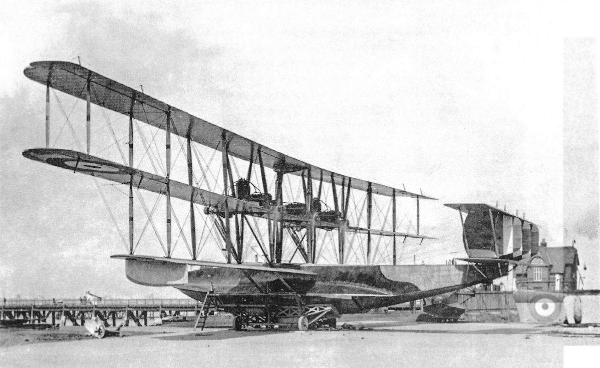
The Fury with its modified tail-unit.
Flanders B.2
L. HOWARD FLANDERS was one of Britain’s pioneer aircraft constructors. In November, 1909, . he joined J. V. Neale as manager, and gained valuable practical experience with the early Neale aircraft. In 1911 he designed and built a handsome monoplane powered by a 60 h.p. Green engine; this machine was quite successful. In 1912 the War Office ordered four Flanders monoplanes of an improved type, powered by the 70 h.p. Renault engine. These machines were complete and about to be handed over to the R.F.C. when the infamous “monoplane ban” came into force.
The British Military Trials were held on Salisbury Plain in 1912, and one of the entrants was a biplane of Flanders design. Unfortunately, the biplane did not receive its engine, a 100 h.p. A.B.C., in time to enable it to compete in the flying tests. It was later fitted with a 40 h.p. A.B.C. engine, and flew well despite the small amount of power available. The designed speed of the Flanders biplane with the 100 h.p. engine was 83 m.p.h., and it caused a minor sensation by flying at 55 m.p.h. with three people on board when fitted with the 40 h.p. engine.
In the autumn of 1913 the aircraft was fitted with the 60 h.p. Isaacson seven-cylinder radial engine, which proved to be a very satisfactory power unit. In this form the Flanders B.2 flew frequently and well in the hands of A. Dukinfield-Jones.
The Flanders biplane had several unusual structural features. As the illustration shows, the fuselage was remarkably deep. It had a single central longeron forming a kind of keel along its underside; behind the cockpits the fuselage tapered to a triangular cross-section at the tail. All the longerons in the nose were of hickory, and in the rear portion of the fuselage they were of ash. The passenger occupied the front cockpit, from which he had a good view in forward and downward directions.
The central skid of the undercarriage was made of hickory, and was spliced to the keel of the fuselage. Each wheel was on a separate half-axle hinged at its inner end to the central skid. Independent springing was provided by means of twin coil springs in compression on each leg of the undercarriage.
The wings were of unequal span and chord, and were characterised by the absence of any conventional centre-section bracing. The spars of the wing panels were spruce, whilst those of the centre-section were of ash. Lateral control was by wing-warping.
The tailplane was a semi-circular surface, and the rudder was strikingly similar to that of the Avro 504.
By June, 1914, the Flanders B.2 had been fitted with yet another engine. The new power unit was a 70 h.p. Gnome rotary which had been modified to have the valves of an 80 h.p. Gnome.
On the outbreak of war the machine was bought by the Admiralty and was allocated to the R.N.A.S. station at Great Yarmouth. The delivery flight was punctuated by a series of forced landings, after one of which the machine was dismantled with more vigour than care, and was delivered at Yarmouth in pieces.
It was intended to scrap the Flanders, but Lieutenant R. J. Bone ordered the machine to be rebuilt. New spars were fitted to the wings and new fabric was applied, and the aircraft was rigged by reference to a photograph which showed it in its original state. Lieutenant Bone tested the Flanders, but it proved to be tail-heavy. A new and larger tailplane was therefore designed and made in the station workshop, and with it the machine was passed as fit for use. There is no record that the Flanders biplane was ever flown in any operational capacity, however.
SPECIFICATION
Manufacturer: L. Howard Flanders, Brooklands, Byfleet.
Power: 40 h.p. A.B.C.; 60 h.p. Isaacson; 70 h.p. Gnome.
Dimensions: Span: upper 41 ft, lower 29 ft. Length: 31 ft 10 in. Chord: upper 6 ft 7 in., lower 5 ft 1 in. Dihedral: nil. Span of tail: 8 ft 6 in. Wheel track: 8 ft. Airscrew diameter: 8 ft 6 in.
Areas: Wings: upper 270 sq ft, lower 125 sq ft, total 395 sq ft. Tailplane: 28 sq ft. Elevators: 14 sq ft. Rudder: 10 sq ft.
Weights: 40 h.p. A.B.C. - Empty: 670 lb. Loaded: 1,110 lb. Isaacson - Empty: 1,000 lb. Loaded: 1,571 lb.
Performance: 40 h.p. A.B.C. - Maximum speed: 56 m.p.h. Initial rate of climb: 200 feet per minute. Isaacson - Maximum speed: 65 m.p.h. Endurance: 4 1/2 hours.
Tankage: Main (pressure) tank: 15 gallons; service (gravity) tank: 7 gallons; total: 22 gallons.
Service Use: Flown at R.N.A.S. Station, Great Yarmouth.
Serial Number: 918.

THE ISAACSON ENGINED FLANDERS BIPLANE. - Three-quarter view from the front.
Grahame-White Type XV
THE Grahame-White Type XV was a development of the original Grahame-White Box-kite of 1912, and the designation Type XV seems in fact to have been applied to the Box-kite and its two derivatives. There are grounds for believing that one of the earlier forms of the aircraft may have been known as the Grahame-White Type XII, but the type number XV gained general application to all versions.
The original machine was typical of the box-kite form of aeroplane, and resembled the Farman biplane of 1909 which set a popular and widely-imitated style in aircraft design. Whereas the Farman and most other contemporary box-kite aeroplanes had only single-surface covering on the mainplanes, the Grahame-White biplane had double-surface covering. The Grahame-White machine of 1912 had equal-span wings with four pairs of interplane struts on each side of the aircraft centre line. Ailerons were fitted to upper and lower wings, but were not laterally connected by balance cables. There were both forward and rear elevators. The tailplane was set high and, like the mainplanes, was square-cut. Two rudders were fitted, and earned the machine the nickname of “The Bi-rudder Bus”. The engine was the inevitable 50 h.p. Gnome, and the two occupants sat in complete exposure on a remarkably sketchy framework attached to the lower wing.
On November 27th, 1913, a Grahame-White Box-kite was the vehicle for an experiment which gave a foretaste of the fighting potentialities of aircraft. On that date, a Lewis machine-gun was fired from a Box-kite piloted by Marcus D. Manton; the gunner was Lieutenant Stellingwerf of the Belgian Army, who sat in a small seat mounted below and behind the pilot’s position. The air-firing tests were made at Bisley, and despite bumpy air Stellingwerf hit a ground target with 11 shots out of 25 on his first attempt, and with 15 out of 47 on his second.
The first form of the Grahame-White Box-kite saw service in some numbers, both at the Grahame-White flying school at Hendon before the war and with the R.N.A.S. after the outbreak of hostilities.
In 1914 and 1915 a slightly improved version of the design appeared. The basic airframe remained unchanged, but substantial, slightly tapered extensions were added to the upper wings, and balance cables connected the ailerons. A 60 h.p. Green engine was fitted, and much smaller tail-skids were used; these smaller skids were subsequently fitted to the original equal-span Box-kites. The extended Box-kite was used at the Grahame-White flying school early in the war. Among the distinguished aviators who learned to fly on the early Grahame-White Box-kite was Andre de Meulemeester, the celebrated Belgian fighter pilot.
<...>

Grahame-White Type XV. The basic form of the Grahame-White XV, a simple box-kite biplane.

Grahame-White Type XV. The second form of the design, with dual control and extensions on the upper wings. The engine of this machine is a 60 h.p. Green. (The number on the rudder is not an official serial number.)
Grahame-White Type XIII
CLAUDE GRAHAME-WHITE, that great pioneer of British aviation, produced his first aeroplane in 1910. That was the Grahame-White Baby, and several other types of widely different forms appeared in the succeeding years.
For the Circuit of Britain seaplane race of 1914, J. D. North designed a handsome single-engined biplane with very short twin floats; the machine was powered by an English-built 100 h.p. Gnome Monosoupape rotary engine, and bore the Grahame-White type number XIII.
The outbreak of war led to the cancellation of the race. When the Grahame-White Type XIII was first tested, its short floats were its undoing: when the throttle was opened the seaplane nosed over. The machine was retrieved from the water, repaired, and was thereafter modified to have a wheel undercarriage. The Grahame-White company looked upon the modified machine as a potential two-seat scout, but it was not adopted for Service use. It seems probable, however, that it was used for training purposes at Hendon.
The single-bay wings were of equal span and had “N” interplane struts; ailerons were fitted to the upper wing only. One of the least desirable features of the Grahame-White Type XIII was the use of auxiliary flying wires which ran from the extremities of the undercarriage axle to both spars of the lower mainplane. The rear portion of the fuselage resembled that of the Morane-Saulnier Type G monoplane, which the Grahame-White company built under licence as their Type XIV; and there was no fixed tailplane. The rudder had a balance area below the fuselage. Transparent panels were let into the fuselage sides, and the roots of the lower mainplanes were also covered with transparent material to improve the pilot’s downward view.
The pilot occupied the rear cockpit, and the distance between him and his observer was too great to enable the machine to function satisfactorily as a reconnaissance type.
SPECIFICATION
Manufacturers: The Grahame-White Aviation Co., Ltd., Hendon.
Power: 100 h.p. Gnome Monosoupape.
Dimensions: Span: 27 ft 10 in. Length: 26 ft 6 in. Chord: 5 ft 6 in. Gap: 5 ft 6 in. at wing-tips. Dihedral: upper, nil; lower, 2. Incidence: upper 50, lower 30. Span of tail: 8 ft 9 in.
Areas: Wings: 290 sq ft.
Weights: Empty: 1,040 lb. Loaded: 1,800 lb.
Performance: Maximum speed: 85 m.p.h. Endurance: 5 1/2 hours.
Tankage: Petrol: 50 gallons. Oil: 9 1/2 gallons.
Service Use: Flown at R.N.A.S. Station, Hendon.
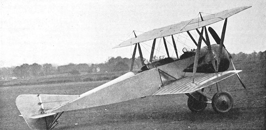
Two-seat Grahame-White Scout of 1914.
Grahame-White Type XV
<...>
The ultimate form of the design, which appeared in 1916, looked much less primitive, thanks to the provision of a nacelle for the crew, and was the first version to have full dual control. The forward elevator was removed, but the wings retained the extensions. Power was provided by an 80 h.p. Gnome or Le Rhone engine. Most machines had the short tail-skids and balance cables for the ailerons, but No. 1600 (which provided the type with its Admiralty designation, viz., Grahame-White Biplane Type 1600) had long tail-skids and was without balance cables. It seems quite probable that some at least of the machines which appeared in this final form were produced by rebuilding early versions of the Box-kite design.
The Grahame-White Box-kite in its several forms gave good but undistinguished service as an elementary trainer with both the R.F.C. and R.N.A.S. It was, in fact, regarded by the Admiralty as a standard type. A few went to Australia, where they were used at the Australian Central Flying School at Point Cook. At least three survived the Armistice and went on to the British Civil Register as K. 111 (later G-EABB), K.112 (G-EABG), and K.113 (G-EABD). Presumably they were intended for use at the Grahame-White flying school, but the registrations of the first two were cancelled in May, 1920, and G-EABD was cancelled on January 10th, 1923, probably long after it was last used.
SPECIFICATION
Manufacturers: The Grahame-White Aviation Co., Ltd., Hendon, London. Power: 50 h.p. Gnome; 60 h.p. Green; 80 h.p. Gnome; 80 h.p. Le Rhone.
Service Use: Grahame-White School of Flying, Hendon; R.N.A.S. stations at Chingford, Eastbourne and Eastchurch; No. 31 Training Squadron, R.F.C., Wyton; No. 65 Squadron R.F.C. (training only); Australian Central Flying School, Point Cook, Werribee, Victoria.
Production and Allocation: A total of 135 Grahame-White Type XV biplanes were built for the R.F.C. and R.N.A.S. The batch A.1661-A.1710 were delivered to the R.F.C., twenty-three in 1916 and twenty-seven in 1917. The others were delivered to the R.N.A.S.
Serial Numbers: 1600; 3151-3162, built under Contract No. C.P.69521/15; 3607-3616, built under Contract No. C.P.101607/16; 8305-8316; 8752-8801; A.1661-A.1710.
Notes on Individual Machines: 3152 and 3610 were used at the R.N.A.S. Station, Chingford; 8752 and 8753 were used at the Australian C.F.S., Point Cook; A. 1685 was used by No. 31 Training Squadron, R.F.C.

Grahame-White Type XV. The ultimate form of the type with forward elevator removed and a nacelle fitted.

Grahame-White Type XV for the R.F.C. This machine has double-acting ailerons and short tail-skids (compare with No. 1600, which had single-acting ailerons and long tail-skids).
Grahame-White Type 18
THE design of the Grahame-White Type 18 was begun in 1915, and it appears that it was designed for the Admiralty as a single-engined bomber. It was a massive biplane with equal-span wings, powered by a 285 h.p. Sunbeam Maori engine, and appeared to be in the same general category as the Short and Wight bombers.
There were four sets of interplane struts on each side, but the innermost pair served instead of the more conventional centre-section struts. The mainplanes could be folded. The fuselage was basically the usual cross-braced wooden box girder, but was carefully faired throughout its length to a more or less elliptical cross-section; and the undercarriage was a substantial vee structure with the addition of a nose-wheel. The tailplane was rectangular; and the low aspect-ratio fin and rudder were made of steel tube. The engine had a flat frontal radiator, and a large single exhaust stack was fitted.
Fuel was carried in a large tank in front of the pilot, and its size is sufficient indication that the machine was designed to have a long range. The pilot’s control column was surmounted by a wheel of appropriate proportions for the control of the ailerons.
The large wing area and reasonably clean design hinted at good weight-lifting ability, but no doubt the advent of the Handley Page O/100 was one reason for the non-adoption of the Grahame-White Type 18.
SPECIFICATION
Manufacturers: The Grahame-White Aviation Co., Ltd., Hendon, London.
Power: 285 h.p. Sunbeam Maori.
Armament: The observer had a ring-mounting on his cockpit, presumably for a free Lewis machine-gun.

The sole Grahame-White Type 18 prototype, before covering.
Grahame-White Type 20
THE Grahame-White type number 19 was allotted to the Breguet V, ten of which, powered by the 250 h.p. Rolls-Royce engine, were built by the Grahame-White company under licence. The next true Grahame-White type was the Type 20, a small single-seat scout, powered by the 80 h.p. Clerget 7Z engine, which appeared in 1916.
The fuselage was faired to a circular cross-section throughout its length, and the pilot’s cockpit was directly under the centre-section; the main fuel tank was immediately behind the cockpit. There was no tailplane, only a balanced elevator reminiscent of that of the Morane-Saulnier Type G monoplane which the Grahame-White company had built under licence as their Type XIV. An alternative power-unit for the Type 20 was the 80 h.p. Le Rhone.
The single-bay wings were, for 1916, of unusually thick section and were rigged with a very large gap.

The Grahame-White Type 20 scout.
Grahame-White Experimental Twin
THE serial number A.8964 was allotted to a large Grahame-White biplane of which little is known, save that it had twin airscrews. Whether that implied twin engines or a central inboard power plant is uncertain; and it is equally uncertain whether the aircraft was completed.
Grahame-White Experimental Two-Seater
THIS angular little biplane obviously owed something to the D.H.6, for which type the Grahame-White Aviation company received its first contract on January 13th, 1917. In fact, the Grahame-White machine appeared to incorporate some D.H.6 components, and there can be little doubt that it was designed in 1917. The Grahame-White two-seater reflected the square-cut wings, external guide pulleys for aileron control cables, strut-linked ailerons, and communal cockpit of the D.H.6, but had rather better lines. The engine appeared to be the 75 h.p. Rolls-Royce Hawk, and an American look was given to the aircraft by the use of a frontal radiator which was similar in shape to those used on contemporary American aeroplanes.

Grahame-White Experimental two-seater.
Grahame-White Type 21
IN April, 1917, the Grahame-White company produced a second single-seat scout. This was a handsome little single-bay biplane, characterised by its “I” interplane struts and clean lines. The fuselage was faired only sufficiently to blend the circular engine cowling into the rectangular cross-section, but a top decking was fitted aft of the cockpit.
The tail-unit was more conventional and of more pleasing appearance than that of the Type 20. The mainplanes had pronounced stagger, and there were ailerons on all four wings. As in the Grahame-White Type 20, the pilot sat directly under the centre-section with the fuel tank behind him.
The care which had obviously been taken to reduce drag was well repaid, for the Grahame-White Type 2i had the remarkable speed of 107 m.p.h. on no more than 80 h.p. provided by the Le Rhone engine.
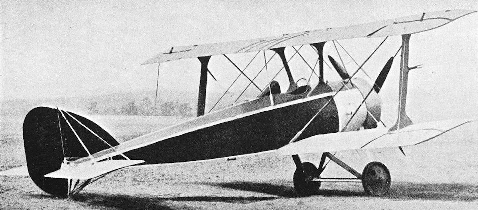
The attractive, but anachronistic Grahame-White Type 21.
Grahame-White E.IV, the Ganymede
THE design of the Ganymede was completed in 1918. The machine was intended to be a long-range day bomber, and in general layout it resembled the three-engined Caproni biplanes and triplanes.
The central nacelle had a pusher engine installed behind the wings, while each of the two fuselages had a tractor engine at its forward end.
The Ganymede was designed for three 400 h.p. Liberty engines, but the manufacturers had to be content with three 270 h.p. Sunbeam Maoris. The large spinners and good aerodynamic entry of the tractor engines were marred by the large exhaust manifolds and stacks, and by the large flat radiators. There was a gunner in the extreme nose of the central nacelle, and each fuselage contained a gunner. Not only did each side gunner have a Scarff ring-mounting on top of his fuselage behind the wings, but an opening in the bottom of each fuselage enabled the gunners to repel attacks from behind and below.
Balanced ailerons were fitted on both upper and lower wings, and the elevators of the biplane tail unit also had horn balances. There were three fins and three rudders.
The use of engines of less than the designed power inevitably reduced the Ganymede’s performance. The signing of the Armistice prevented development of the design, but the aircraft survived for a time as G-EAMW on the Civil Register.
SPECIFICATION
Manufacturers: The Grahame-White Aviation Go., Ltd., Hendon, London.
Power: Three 270 h.p. Sunbeam Maori.
Dimensions: Span: 89 ft 3 in. Length: 49 ft 9 in. Height: 16 ft. Chord: 10 ft 3 in. Gap: 9 ft 3 in. Stagger: nil. Span of tail: 29 ft. Airscrew diameter: 3-14 metres (approximately 10 ft 3 1/2 in.).
Areas: Wings: 1,660 sq ft. Ailerons: each 50 sq ft, total 200 sq ft. Tailplanes: 254 sq ft. Elevators: 114 sq ft. Fins: 30 sq ft. Rudders: 50 sq ft.
Weights: Empty: 11,500 lb. Loaded: 16,000 lb.
Performance: Maximum speed at ground level: 105 m.p.h.; at 10,000 ft: 93 m.p.h. Estimated speed with Liberty engines: 120 m.p.h. at ground level. Endurance: 9 hours at 10,000 ft.
Tankage: Petrol: 400 gallons.
Armament: Three free Lewis machine-guns: one on Scarff ring-mounting at nose of nacelle; one on Scarff ring on cockpit in each fuselage; lower rear tunnel position in each fuselage.
Serial Numbers: C.3481-C.3483, ordered under Contract No. A.S.38051.
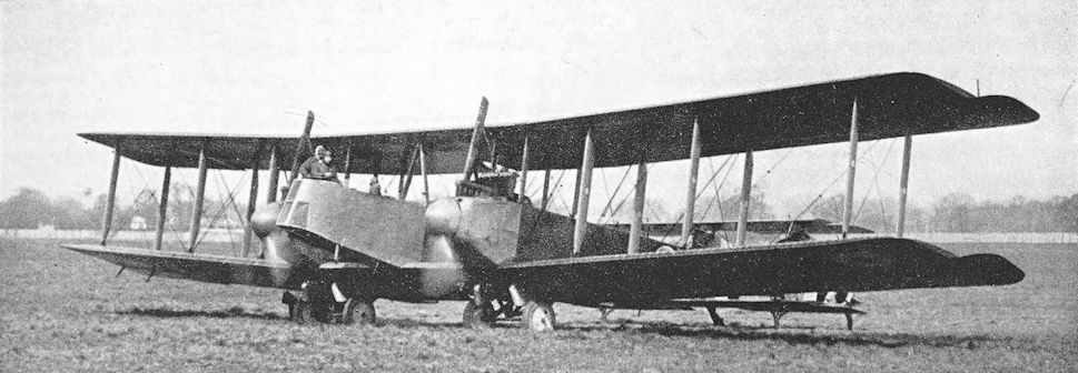
Grahame-White Ganymede.
Hall School Biplane
J.L. HALL was one of the pre-war British exhibition pilots: he took his R.Ae.C. aviator’s certificate .(No. 291) at Hendon on September 17th, 1912, flying a Bleriot monoplane. In the summer of the following year he opened a flying school at Hendon.
His school had at least one Caudron biplane up to the outbreak of war, but on November 7th, 1914, there occurs the first mention of the Hall Biplane: on that aircraft J. H. Rose “took his ticket” at Hendon on that date.
The Hall Biplane consisted of the wing structure and undercarriage of a Caudron G.II married to a new fuselage and tail-unit: there may have been some direct connexion with the school’s original Caudron. The mainplanes were quite unchanged in any way, and retained the characteristic covering which gave a double-surface wing only between the spars. Lateral control was by wing-warping. The lower booms of the original Caudron were cut off where the first inter-boom struts were situated, and provided a useful pair of skids in the undercarriage.
Power was provided by an 80 h.p. Gnome rotary motor, and the simple fuselage carried an equally simple tail-unit and tail-skid.
The Hall Biplane was still in use at the end of 1915, by which time thirty-five pilots had qualified for their R.Ae.C. certificates on it.
SPECIFICATION
Constructors: The Hall Aviation Co., London Aerodrome, Hendon.
Power: 80 h.p. Gnome.
Dimensions: Span: 38 ft 9 in.
Areas: Wings: 300 sq ft.

Hall Biplane.
Handley Page Type G
MR (later Sir) Frederick Handley Page entered the aircraft industry in 1908, when he founded the organisation which, on June 17th, 1909, was incorporated as a limited liability company under the title of Handley Page, Ltd. In its early years, the company built several aeroplanes to the designs of others: among these were a Weiss monoplane, the Planes Ltd. biplane, and the Deverall Saul quadruplane.
The Weiss monoplane had a considerable influence upon the earliest aeroplanes designed by Handley Page, Ltd., for all the monoplanes had wings with curved, swept-back leading edges, similar to those of the Weiss machine. This configuration was adopted solely to achieve longitudinal stability, for Jose Weiss had earlier demonstrated its effectiveness. Tried experimentally on gliders, the swept-back wing was used on the Handley Page Types A, C, D, E and F.
All were monoplanes, but in 1913 there emerged from the new Handley Page works at 110 Cricklewood Lane a biplane, known as the Handley Page Type G. Its design embodied all the valuable experience gained with its monoplane predecessors, and it inherited their curved, swept-back wing plan-form. Ailerons, fitted to the upper wing only, replaced the wing-warping of the monoplanes; these ailerons had pronounced wash-out of incidence. Power was provided by an Anzani ten-cylinder radial engine of 100 h.p.
The structure of the aeroplane underwent several modifications from time to time. In its original form the Type G had a twin-skid undercarriage, and both occupants sat in tandem in the long undivided cockpit. The rounded top-decking of the fuselage tapered down to the fin, and there was a bath-like fairing on the underside of the fuselage beneath the cockpits. There were three bays of interplane struts, the outermost consisting of a slender vee arrangement. It was not long before an additional short strut was added to the outermost struts, bracing the leading edge of the lower wing to a point about a quarter of the way up the rear interplane strut; and later the long forward strut of the vee was replaced by a shorter strut which braced the leading edge of the upper wing to the interplane strut.
The rudder and elevators had well-rounded trailing edges, and the fin and tailplanes were of triangular shape; the leading edge of the fin was slightly concave. Early in its career, the Handley Page Type G gave a striking demonstration of its stability by flying with its fin and tailplane removed.
The test-flying of the machine was done by E. R. Whitehouse, who put it through the official tests at Farnborough on December nth, 1913: during these tests it flew successfully with two passengers. In May, 1914, the Type G was flown by W. Rowland Ding for the first time, within a week or two of taking his R.Ae.C. aviator’s certificate. On one of his early flights, Ding damaged the undercarriage on landing, and the opportunity was taken to fit a neater undercarriage consisting of two plain wooden vees. By this time a short piece of top decking separated the two seats.
The Handley Page biplane was bought by a syndicate headed by Ding. He flew the machine regularly at flying meetings, and in a tour of the provinces made in the summer of 1914 he covered more than 10,000 miles and carried 200 passengers in the Type G.
Soon after the outbreak of war the machine was bought by the Admiralty, and was based at Hendon for training and Home Defence duties. By this time the appearance of the Type G had again undergone a change: the belly fairing was extended farther aft, a smaller fin was fitted, and fabric-covered wheels replaced the original uncovered wheels. Early in 1915 it was transferred to Chingford, and was flown there by Warren Merriam.
Its career was nearly brought to an untimely end because of its swept-back wings. At that time, that particular design feature was a characteristic of several enemy types, and while the Type G was flying over London it was riddled by the fire of over-zealous ground gunners who had mistaken it for a German biplane. Fortunately no severe structural damage was caused, and neither occupant was wounded.
The machine was not particularly good as a trainer, for its inherent stability made it too easy to fly. It survived until August, 1915, when it was badly damaged in a ground accident at Chingford. It was then written off.
SPECIFICATION
Manufacturers: Handley Page, Ltd., no Cricklewood Lane, London, N.W.
Power: 100 h.p. Anzani.
Dimensions: Span: upper 44 ft, lower 32 ft. Length: 25 ft 1 in. Chord: Maximum 6 ft 6 in. Dihedral: 2° on centre line of both rear spars. Airscrew diameter: 8 ft 6 in.
Areas: Wings: upper 272 sq ft, lower 166 sq ft, total 438 sq ft. Ailerons: each 28 sq ft, total 56 sq ft. Tailplane: 32 sq ft. Elevators: 19 sq ft. Fin: 6 sq ft. Rudder: 12-5 sq ft.
Performance: Maximum speed at ground level: 73 m.p.h.; at 3,000 ft: 70 m.p.h.
Armament: One Webley revolver, worn by the pilot.
Service Use: Used at R.N.A.S. Stations at Hendon and Chingford.
Serial Number: 892.

Handley Page Type G. This illustration shows the modified outer interplane struts.

The Handley Page Type G biplane in its original form.

Handley Page Type G in its final form, here seen in November 1914 in use at Hendon as a trainer with the official serial number 892. Note the vee undercarriage, covered wheels, extended belly fairing, smaller fin and enlarged rudder.
Handley Page O/100 and O/400
IN 1913 the Daily Mail offered a prize of £10,000 to be won by the pilot of the first aeroplane to fly across the Atlantic Ocean. One of the three aircraft which were designed and built for the express purpose of attempting the trans-Atlantic flight was the Handley Page L/200, a large single-motor biplane which had a 200 h.p. Salmson engine. This machine’s capabilities were never put to the test, for the war began before it was completed.
The historical significance of the Handley Page L/200 lies in the fact that it was the first expression of Mr Handley Page’s belief in the advantages inherent in large aeroplanes, particularly when it was essential to carry a heavy load.
This belief found further expression when, in December, 1914, the Admiralty issued a statement of their requirements for an aeroplane capable of making oversea patrols with a load of bombs. The specification required the aircraft to have two engines, to carry a crew of two and six 112-lb bombs, and to have a maximum speed of at least 72 m.p.h. The Handley Page design which was shown to Commodore Murray F. Sueter, then the Director of the Air Department of the Admiralty, was for a large biplane powered by two 120 h.p. Beardmore engines. The design impressed him, as also did Mr Handley Page’s faith in big aeroplanes. Apparently determined to outdo even the ambitious requirements of the original specification, Commodore Sueter asked Mr Handley Page to provide a “bloody paralyser” of an aeroplane. That specification may have been technically vague, but the interpretation of it was magnificent.
Assisted by G. R. Volkert, Mr Handley Page revised the design accordingly, and an order was given for the construction of the machine. The re-designed aircraft had a longer nose than the original project; two 150 h.p. Sunbeam engines were to replace the Beardmores, and the wing span was no less than 100 feet.
Construction began immediately, and the Handley Page factory worked seven days a week to complete the O/100, as the new machine had been designated. It presented many problems, for it was larger than any aeroplane which had been built in this country up to that time. No one had any practical experience of the construction of aircraft of such size, and every spar, strut and fitting was tested to destruction before it was fitted; yet the prototype was flown less than a year after the date of ordering.
While the O/100 was being built, the Rolls-Royce company were developing the two aero-engines which were to win distinction as the Eagle and Falcon. By August, 1915, the engine which was later to be known as the Eagle had shown itself to be capable of developing 300 h.p. at 2,000 r.p.m., but to ensure reliability in running the engine was rated at 250 h.p. at 1,600 r.p.m. Two of these Rolls-Royce engines were installed in the O/100.
The engines were mounted in armoured nacelles, each of which contained an armoured fuel tank. The crew had an enclosed cabin, and were protected by bullet-proof glass and armour plate.
The completed O/100 was transported by road from Cricklewood to Hendon during the night ol December 17th/18th, 1915, and took off for the first time at 1.51 p.m. on the 18th. As the trials of the aircraft progressed, various modifications were made. One of the first was the removal of the cabin enclosure: in the course of a flight from Hendon to Eastchurch the cabin collapsed and was never used again. Most of the armour plate was also removed. The official trials of the O/100 were carried out at Eastchurch, beginning in January, 1916.
For the structure of the O/100, its designers wisely contented themselves with adhering to the type of construction with which they were familiar; but it had to be carried out on a much larger scale than anything that had gone before. The fuselage was a cross-braced box girder which was built in three parts: the central portion embodied the bomb bay, and to it were attached the nose and tail portions. The longerons of the tail portion were of hollow spruce, but elsewhere solid spruce was used.
The wings were also built in sections, the upper in five and the lower in four. The box spars and all interplane struts were built up, and large horn-balanced ailerons were fitted to the upper wings only. The long extensions of the upper wing were braced from king-posts immediately above the outermost interplane struts. The great size of the O/100 presented problems of accommodation, and the wings were made to fold to conserve hangar space.
The tail-unit was a biplane structure, and the vertical surfaces consisted of a single central fin and two outboard rudders: the fin was mounted on top of the fuselage and, on the O/100, had its leading edge in advance of the tailplane. There were four separate horn-balanced elevators. The incidence of the tailplane could be altered on the ground only.
The original elevators were not satisfactory. The trouble lay in their horn balances, which were experimentally stripped of their fabric in an endeavour to find a remedy; but finally all save only a very small portion of balance area was removed completely. No attempt was made to modify the shape of the horizontal tail surfaces, and the O/100 was left with the overhanging elevators which became a well-known characteristic of the type.
The engines were mounted midway between the wings and drove tractor airscrews of opposite hand. The nacelles of the O/100 were, of necessity, long, for each accommodated one of the main fuel tanks, and their tail fairings extended well behind the rear interplane struts. The basic structure of each nacelle was of steel tube. Frontal radiators with vertical shutters later replaced the divided, side-mounted radiators which appeared on some of the early O/100s.
The undercarriage was a substantial but somewhat complicated affair, built almost wholly of faired steel tube. Each wheel had a large shock-absorber, and 800 X 150 mm or 900 X 200 mm tyres were fitted. There were no brakes: reliance was placed upon the massive sprung tail-skid for braking purposes.
The prototypes had no provision for defensive armament; but production O/100s had a cockpit in the extreme nose of the fuselage, surmounted by a Scarff ring-mounting, and positions were provided behind the wings both above and below the fuselage. The bombs were suspended by their noses inside the fuselage; the bomb-cells were closed by spring-loaded doors which opened under the weight of the falling bomb.
Forty O/100s were delivered to the R.N.A.S., beginning in September, 1916, with those which went to Manston to equip the training squadron there. This total included the prototypes, which were modified to production standard before delivery. It was originally intended that the O/100 should be produced by Mann, Egerton & Co., Ltd., of Norwich. For the purpose, that firm had a special large building erected urgently in the space of only six weeks early in 1916. Owing to a change in official plans, however, the planned production did not take place, and Mann, Egerton & Co. built Short Bombers instead of O/100s.
The first operational unit to receive the big Handley Page was the R.N.A.S. 5th Wing at Dunkerque, which received its first O/100 in November, 1916. It was flown to France by Squadron Commander John Babington, with Lieutenant Jones and Sub-Lieutenant Paul Bewsher as crew; and it was followed two weeks later by a second machine flown by Sub-Lieutenant Waller.
After a false start on Christmas Eve, 1916, the third Dunkerque-bound O/100 set course for France just before noon on January 1st, 1917. Its crew were Lieutenant Vereker (pilot), Lieutenant Hibbard (observer), Leading Mechanics Kennedy and Wright, and Air Mechanic First Class W. W. Higby. It was followed about a quarter of an hour later by a fourth machine (Sub-Lieutenant Sands, W. Poile, S. Bassett and D. E. Wade). Third time was unlucky for the O/100, for the third machine was delivered intact to the enemy and had no opportunity to demonstrate the warlike qualities implied in the name of “La Amazon” which had been given her by her crew. After flying for some time over and in unbroken cloud, Vereker landed in the first suitable field he saw after breaking cloud at 500 feet. By bad luck the field was twelve miles inside enemy territory near Laon, and an example of Britain’s latest aerial weapon was delivered undamaged into the enemy’s hands.
German reports indicate that the O/100 was investigated with proverbial Teutonic thoroughness, and it is said that it was once flown by Manfred von Richthofen. For propaganda purposes at the time it was alleged that the design of the German Gotha bombers was copied from or at least inspired by the O/100, and unfortunately that fable survived the war and gained considerable credence. The Gotha went into production in the autumn of 1916, and a German official memorandum issued at that time stated that thirty Gotha G.IVs would be ready by February 1st, 1917. The first production Gothas were in fact delivered to German bombing squadrons in that month. Apart from the date’s incompatibility with any copying of the British design, the Gotha was a totally different aeroplane from the Handley Page, and was not even comparable in size.
The three O/100s which reached France safely were the only Handley Pages to go there until the beginning of April, 1917, when four went to Dunkerque to form the nucleus of No. 7 Squadron, R.N.A.S. At least one machine went to the R.N.A.S. 3rd Wing at Luxeuil. Early Service use of the O/100 recalled the terms of the original Admiralty specification of December, 1914, for No. 7 Naval flew their machines on daylight patrols off the coast. On April 23rd, 1917, three O/100s, each loaded with fourteen 65-lb bombs, attacked five German destroyers off Ostend and left one listing badly after being stopped by several direct hits.
Three days later, however, an O/100 was brought down in a similar exploit and was lost. The type was thereafter withdrawn from daylight operations and confined to night bombing, a duty which had been pioneered some six weeks earlier by a single O/100 of the R.N.A.S. 3rd Wing which attacked the railway station at Moulin-les-Metz on the night of March 16th/17th, 1917.
The O/100s were so few in number that for some weeks the night raids were carried out by single machines. Nevertheless, a single O/100 was a potent weapon in its day. Whereas the Short Bombers of the R.N.A.S. 5th Wing could carry only eight 65-lb bombs, each O/100 could take up to sixteen 112-pounders. To transport an equal load of bombs six D.H.4s were required, and their fuel consumption was 120 gallons per too miles as against the 54 gallons per 100 miles of the O/100. Moreover, the crews of the D.H.4s would total twelve men, whereas the O/100 required only a pilot and two observers.
The Handley Pages of the 5th Wing bestowed their nocturnal attentions upon the enemy destroyer and U-boat bases at Bruges, Ostend and Zeebrugge; while in the south of France the 3rd Wing’s attacks on enemy industrial centres paved the way for the strategic operations of the Independent Force in the following year.
In the preparations for the British offensive of 1917 in Flanders, the Dunkerque O/100s assisted by bombing enemy railway centres, notably in and around the Thourout-Cortemarck-Lichtervelde railway triangle. By the middle of August, 1917, R.N.A.S. Squadrons Nos. 7 and 7A possessed a total of twenty O/100s. No. 7A had been formed from a nucleus provided by No. 7 during the previous month, and was itself to provide the nucleus for the formation of No. 14 (Naval) Squadron, which was formed on December 9th, 1917. Some of these O/100s dropped 9 1/2 tons of bombs on the Thourout-Cortemarck-Lichtervelde triangle during the night of September 25th/26th, 1917. Thereafter they confined their attentions to the aerodromes from which the Gothas flew to bomb England, and made life unpleasant on the enemy aerodromes of Gontrode and St Denis Westrem.
By this time, however, four of their number had been withdrawn to Redcar on September 5th, 1917, in an endeavour to counteract the increasing depredations of enemy submarines off the mouth of the Tees. These O/100s made inshore patrols for four weeks, and bombed seven of the eleven submarines they sighted during that period. None of the U-boats was sunk, but the presence of the Handley Pages made an improvement in the area.
On October 2nd, 1917, the four O/100s were transferred to Manston as the nucleus of a new bomber squadron. This squadron was originally called “A” Squadron, and was formed for the purpose of making strategic raids against industrial centres in southern Germany. Led by Squadron Commander K. S. Savory, Naval “A” Squadron flew to Ochey to join the 41st Wing on October 17th, 1917. The Wing was the beginning of the Independent Force, R.A.F.
Nine Handley Pages of Naval “A” Squadron opened the 41st Wing’s night-bombing offensive on the night of October 24th/25th, 1917, when they accompanied sixteen F.E.2b’s of No. too Squadron, R.F.C., in an attack on the Burbach works near Saarbrucken. In January, 1918, Naval “A” Squadron was redesignated No. 16 (Naval) Squadron, and remained on night-bombing duties until the Armistice.
Only one O/100 was used outside the European theatre of war. In June, 1917, this machine flew from England to Mudros on the island of Lemnos in the Aegean Sea, whence the R.N.A.S. launched a bombing offensive against the Turks in July. The 2,000-mile flight was accomplished in a flying time of 55 hours.
It was a remarkable achievement at that time, and was made by way of Paris, Rome and the Balkans: while crossing the Albanian Alps at 10,000 feet the water in the radiators froze. The crew of the Handley Page were Squadron Commander K. S. Savory, Flight-Lieutenant H. McClelland, Lieutenant P. T. Rawlings, R.N.V.R., Chief Petty Officer 2(E) J. L. Adams, and Leading Mechanic (C) B. Cromack. The O/100 carried a spare engine, two spare airscrews, hammocks, tents, and a full set of spares; the aircraft weighed 6 1/2 tons at take-off.
The chief reason for taking an O/100 to the Aegean was to provide means for bombing Constantinople, a flight of some 200 miles from Mudros. After two abortive attempts, Squadron Commander Savory reached the objective shortly before midnight on July 9th, 1917, and was over the target area for thirty-five minutes, during which time twelve 112-lb bombs were dropped. After nearly three months spent in short-range bombing and anti-submarine patrol, the Handley Page again took off for Constantinople on September 30th, 1917, with Flight-Lieutenant J. Alcock at the controls; but engine failure brought the big machine down in the Gulf of Xeros and all the crew were taken prisoner.
<...>
SPECIFICATION
Manufacturers: Handley Page, Ltd., Cricklewood, London.
Other Contractors: The Birmingham Carriage Co., Birmingham; Clayton & Shuttleworth, Ltd., Lincoln; The Metropolitan Waggon Co., Birmingham; National Aircraft Factory No. 1, Waddon; The Royal Aircraft Factory, Farnborough, Hants.; The Standard Aircraft Corporation, Elizabeth, New Jersey, U.S.A.
Power: O/100: two 250 h.p. Rolls-Royce Mk. II (266 h.p. Eagle II); two 320 h.p. Sunbeam Cossack; four 200 h.p. Hispano-Suiza (experimental installation).
Dimensions: Span: upper 100 ft, lower 70 ft. Length: 62 ft 10 1/4 in. Height: 22 ft. Chord: 10 ft. Gap: 11 ft. Stagger: nil. Dihedral: 4°. Incidence: 3°. Span of tailplanes: 16 ft 7 1/2 in. Track of each undercarriage unit: 4 ft 6 in. Airscrew diameter: 11 ft.
Areas: Wings: 1,648 sq ft. Ailerons: each 86 sq ft, total 172 sq ft. Tailplanes: 111-6 sq ft. Elevators: 63 sq ft. Fin: 14-7 sq ft. Rudders: 46 sq ft.
Tankage: O/100: petrol - 130-gallon tank in fuselage, one 120-gallon tank in each nacelle; total 370 gallons; oil - two 12-gallon tanks.
Armament: The O/100 could carry up to sixteen 112-lb bombs.
Service Use: O/100: R.N.A.S. Squadrons Nos. 7, 7A (later No. 14 Naval and No. 214 R.A.F.) and “A” (later No. 16 Naval and No. 216 R.A.F.). R.N.A.S. 3rd Wing at Luxeuil. Training Squadron at Manston. Aegean: One O/100 flown from R.N.A.S. Station, Mudros.
Production and Allocation: Forty-six O/100s were built.
Notes on Individual Machines: 3116: the first O/100 to land at Coudekerque. 3117: experimental installation of four 200 h.p. Hispano-Suiza engines. 3135: R.N.A.S. 5th Wing, Coudekerque, markings “B 3” on fuselage. 3138: O/100 modified to become O/400 prototype.
Serial Numbers:
Serial Numbers Contractor Contract No. Specified Engines
Handley Page O/100 :
1455-1466 Handley Page C.P.65799/15 Eagle
3115-3142 Handley Page C.P.69522 Eagle
B.9446-B.9451 Handley Page A.S.20629 Cossack
Costs:
Airframe without engines, instruments or armament £6,000 0s.
Rolls-Royce Eagle Mks. II and IV (each) £1,430 0s.
Rolls-Royce Eagle VIII (each) £1,622 10s.
Sunbeam Maori (each) £1,391 0s.
Fiat A. 12bis (each) £1,617 0s.
Liberty (each) £1,215 0s.
Prototype O/100 with modified elevator balances. The small biplane is a Bristol Scout C.

The O/100 No. 3117 with four Hispano-Suiza engines of 200 h.p. each.

Handley Page O/100. The first prototype, No. 1455, modified to production standard.

O/100 стал первым британским тяжелым бомбардировщиком. Этот самолет изменил боевое применение авиации в Первой мировой войне. Удачные действия бомбардировщиков во многом способствовали созданию Королевских ВВС
B9446, the first Cossack-engined ‘intermediate’ O/100, at Cricklewood in November 1917.
B9446, the first Cossack-engined ‘intermediate’ O/100, at Cricklewood in November 1917.
Handley Page O/100 and O/400
<...>
Development of the basic design went on during 1917, and modifications were made as a result of operational experience. Squadron Commander (later Air Marshal Sir) John Babington, who had flown the first O/100 to France, was closely connected with the work of development.
The chief modification was the removal of the fuel tanks from the engine nacelles and the installation of a completely new fuel system. Two cylindrical tanks, each of 130 gallons capacity, were mounted athwartships above the bomb cells, and two 14-gallon tanks were installed in the leading edge of the centre-section above the fuselage: the latter tanks contained the gravity fuel supply. Two wind-driven pumps were fitted, one on either side of the fuselage: these pumps performed the double duty of feeding the carburettors direct and of forcing petrol up to the gravity tanks. In front of each pump was a movable shutter which, by regulating the airstream over the pump’s small airscrew, provided a measure of control over the speed of the pump. The gravity tanks fed the carburettors when the pumps were inoperative, and a hand pump was provided for starting. The oil tanks were mounted in the nacelles behind the engines.
The engines could be started by compressed air: the supply was contained in bottles in the fuselage. Manual starting was effected by a crank handle, and specially reinforced portions of the lower wings provided platforms for the mechanics who had to perform this duty.
The first Handley Page to have the new fuel system was No. 3138, which was tested in its modified form in September, 1917; production machines were given the new designation O/400. The removal of the petrol tanks from the nacelles enabled the latter to be shortened to such an extent that it was possible to fit an ordinary interplane strut between the rear spars of the wings at that point. The shape of the upper rear gun position varied somewhat, and the central fin was moved back until its leading edge was slightly behind that of the tailplanes.
Alternative engines were fitted, probably because of the shortage of Rolls-Royce engines. Even before the prototype O/400 flew, a contract (No. A.S.20629) was placed on July 29th, 1917, for six Handley Pages to be fitted with two Sunbeam engines. The Sunbeam Arab was quoted in at least one official document as the engine in question, but it seems unlikely that the use of two engines of only 200 h.p. each would be worthwhile; and in point of fact B.9446, the first aircraft of this batch of six, had two 320 h.p. Sunbeam Cossacks. These six Handley Pages were, strictly speaking, O/100s, for they had the original outboard fuel tanks, long nacelles and bifurcated rear interplane struts in the engine bay.
The Sunbeam Maori and Fiat A.12bis were fitted to some O/400s, but the Rolls-Royce Eagle in either its Mark IV or Mark VIII form remained the standard power-unit, and the great majority of O/400s had Eagle engines.
In November 1917, the O/100 No. 3117 was tested with four 200 h.p. Hispano-Suiza engines. The engines were arranged in two tandem pairs, and anticipated the arrangement used on the later Handley Page V/1500. This experimental installation was made at the Royal Aircraft Factory at Farnborough, under the direction of Major P. Bishop (who became Chief Inspector of the A.I.D.,and lost his life in 1931 in the R.101 disaster). It was not an unqualified success, for at that time there existed no data relating to the behaviour of an airscrew working in the slipstream of another. This O/100 provided a good deal of information which proved useful in the design of the engine installation for the V/1500.
Experiments were not confined to the power plant, however. Several forms of undercarriage were tested, but none proved to be better than the original, despite its complexity. One machine had ailerons with set-back hinges: balancing was thereby achieved without the use of horn balance areas, and the outer ends of the ailerons were flush with the wing-tips. This may have been a test installation of the ailerons for the V/1500.
It is significant that a French official aircraft recognition book of May, 1918, includes drawings of a modified Handley Page which not only had a simplified undercarriage but a monoplane tail-unit as well. The tailplane is depicted as resting on top of the upper longerons, and there are twin fins and horn-balanced rudders mounted wholly above the tailplane and fairly close together. The undercarriage is shown with only one wheel on either side, and generally resembles the divided undercarriage favoured by Frederick Koolhoven in his B.A.T. designs.
Ironically, the decision to produce the Handley Page machine in quantity was hastened by the Gotha. In the summer of 1917 the Air Board was not convinced that there was a need for heavy bombers. The military members thought only in terms of day bombing, and argued that the R.F.C. preferred speed to weight-carrying capabilities in their bombers. Despite a favourable report on the Handley Page, made by the Admiralty representative on the Board, the military members maintained the view that night bombing was less accurate than day bombing. So confirmed were they in this opinion that, at the meeting of the Air Board on July 23rd, 1917, they decided to postpone all orders for experimental heavy bombers.
The decision was short-lived, for it was roundly denounced by the Controller of the Technical Department, and the question was re-opened by Sir William Weir a week later. The Air Board then approved the ordering of 100 Handley Pages for night bombing and gave further orders for experimental heavy bombers: three prototypes were to be built by Handley Page and Vickers. These orders were for the aircraft which materialised as the V/1500 and Vimy respectively. The contract for the 100 machines, which were built as O/400s, was placed on August 14th, 1917.
Some members of the Air Board still harboured doubts about the usefulness of heavy night bombers, and all were considerably surprised when, on August 10th, 1917, Captain V. Vyvyan, R.N., placed before them information, based on the experience of the R.N.A.S. 5th Wing, which showed not only that the Handley Pages suffered fewer casualties than the day-bombing D.H.4s but that, generally speaking, night bombing was more accurate than day bombing.
The Gothas began to make night-bombing attacks on England on September 2nd, 1917, when two machines of No. 3 Bombing Squadron dropped fourteen bombs on Dover. Other raids of increasing intensity followed, and the Air Board, now forcibly convinced of the effectiveness of night bombers, made haste to order 200 more O/400s. When Sir Douglas Haig’s letter of September 10th, 1917, was laid before the Board, members learned of his request that 25 per cent of any further bombing squadrons sent to France should be equipped as night bombers, and promptly ordered yet another hundred Handley Pages.
Production O/400s did not begin to appear in numbers until the spring of 1918, and in the meantime our heavy night-bombing attacks had been carried out by a mere handful of O/100s.
As already related, Naval “A” Squadron flew its O/100s to Ochey on October 17th, 1917, and became the first heavy bomber squadron of what was later the Independent Force of the R.A.F. It was, in fact, the only heavy bomber squadron of the Independent Force until No. 97 Squadron arrived, equipped with O/400s, on August 9th, 1918. No. 215 Squadron transferred from the Expeditionary Force on August 19th, and No. 115 arrived from England on August 31st. During August, 1918, No. too Squadron began to exchange its F.E.2b’s for O/400s.
Two Handley Pages of No. 215 Squadron, flown by Captain W. B. Lawson and Lieutenant M. C. Purvis, made a profound impression on the Germans when they attacked the Badische chemical works at Mannheim on the night of 25th/26th August, 1918. The first machine glided down from 5,000 feet to 200 feet to deliver its attack in the teeth of searchlights and gunfire, and the second O/400 came in at 500 feet. The enemy regarded the attack as most daring, and the munition workers were demoralised not only by the sight of the apparently indestructible Handley Pages flying at such a low height, but also by the fire from the aircraft’s machine-guns which added to the havoc of their bombs.
It was only in the last three months of the war that the O/400s were used in appreciable numbers; in fact, up to the end of August, 1918, the greatest number of Handley Pages to take off on one night was ten. These machines belonged to No. 216 Squadron, and on the night of August 15th/16th they were bent on attacking Mannheim, Saarbrucken, and the aerodromes at Buhl and Boulay. Only eight of the ten bombed their targets, however, for one machine returned owing to bad visibility and another because of engine trouble. With the advent of the additional squadrons the night-bombing force increased in size: it reached its maximum on the night of September 14th/15th, 1918, when Squadrons Nos. 97, too, 215 and 216 sent off a total of forty Handley Pages to bomb Metz-Sablon, Ehrang, Courcelles, Kaiserslautern, Saarbrucken and Frescaty aerodrome. Nine of the forty were obliged to return with engine trouble, one made a forced landing in our lines, and three failed to return.
Losses of the Independent Force’s Handley Pages were not light: between June and November, 1918, eighteen were reported missing and fifty-one were wrecked.
It was during September, 1918, that the O/400s began to deliver the “block-busters” of World War I. These were bombs of 1,650 lb, three of which were dropped on Kaiserslautern by O/400s on the night of October 21st/22nd, 1918. Two nights later, the destruction caused in Wiesbaden by one 1,650-pounder led the inhabitants to think that a group of bombs chained together had been dropped.
Earlier in 1918, when the tide of war was flowing against the Allies, the Handley Pages of Naval Squadrons Nos. 7 and 14 were diverted to the task of attacking enemy communications. On the night of March 26th/27th, 1918, five machines from each squadron set out to bomb Valenciennes. Seven reached the objective, and their four 250-lb and seventy-six 112-lb bombs did much damage to the crowded railway junction.
In the early hours of May 10th, 1918, seven Handley Pages of No. 214 Squadron cooperated with Naval forces in the attempt to block Ostend harbour. The bombers dropped six 550-lb, fifty-three 112-lb, and twenty-six 25-lb bombs on the German batteries. The same squadron was requested on May 16th to bomb Bruges on every possible occasion, but by the end of the month No. 214 had only six serviceable Handley Pages and the target suffered less than it ought to have done.
Also as part of the plan of cooperation with Naval forces, the locks at Zeebrugge were attacked at 2.25 a.m. on May 28th, 1918, by a Handley Page of No. 214 Squadron, piloted by Captain C. H. Darley. After gliding in over Zeebrugge from the sea with his engines silent, Darley dropped his three 520-lb bombs on the locks.
In Palestine, a single O/400, C.9681, was attached to No. 1 Squadron, Australian Flying Corps. It was flown out from England by Brigadier-General A. E. Borton and Major A. S. C. Maclaren in July, 1918, and did much useful work as a bomber and as a transport carrying supplies for fighting aircraft which were cooperating with Colonel T. E. Lawrence. This O/400 was instrumental in wrecking the enemy’s communications on the eve of Allenby’s offensive: on September 19th, 1918, Captain Ross Smith dropped sixteen 112-lb bombs on the Turkish central telephone exchange at El Affule. After the Armistice this O/400 flew from Cairo to Calcutta by way of Damascus, Baghdad and Karachi. It was to have bombed Kabul during the Afghan War of 1919, but was wrecked in a cyclone while picketed in the open during its flight to the north.
Production of the Handley Page O/400 was undertaken in America by the Standard Aircraft Corporation, from whom 1,500 were ordered. These machines were powered by two 350 h.p. Liberty 12-N engines. The first American-built O/400 made its first flight on July 6th, 1918. Only 107 were delivered to the U.S. Air Service, the first in September, 1918, for the remainder were cancelled when the Armistice was signed. A few American-built O/400s reached England before the end of the war, and were assembled at Ford Junction aerodrome in Sussex and at Shaw and Oldham in Lancashire. It is believed that other American-built O/400s were assembled by Waring & Gillow, Ltd. By November 17th, 1918, ten machines had been assembled in Lancashire. The type did not continue in American service, however, for by June 30th, 1919, only four were in commission and twenty more were in store. (See also the footnote to the table of serial numbers.)
After the war the O/400 in various modified forms pioneered air transportation at home and overseas. For this work its good weight-lifting capabilities were an excellent commendation. The passenger-carrying conversions usually had the fuel tanks removed from the fuselage to the engine nacelles, the position they had occupied on the O/100. Eight O/400s were used by the R.A.F. Communication Wing during the 1919 Peace Conference, and carried passengers and mail between London and Paris. The commercial O/400s (in their O/7 guise) of Handley Page Transport, Ltd., operated a regular service between Cricklewood and Paris later in 1919.
SPECIFICATION
Manufacturers: Handley Page, Ltd., Cricklewood, London.
Other Contractors: The Birmingham Carriage Co., Birmingham; Clayton & Shuttleworth, Ltd., Lincoln; The Metropolitan Waggon Co., Birmingham; National Aircraft Factory No. 1, Waddon; The Royal Aircraft Factory, Farnborough, Hants.; The Standard Aircraft Corporation, Elizabeth, New Jersey, U.S.A.
Power: O/400: Prototype - two 275 h.p. Rolls-Royce Mk. II (322 h.p. Eagle VI). Production - two 250 h.p. Rolls-Royce Mk. IV (284 h.p. Eagle IV); two 360 h.p. Rolls-Royce Eagle VIII; two 275 h.p. Sunbeam Maori; two 260 h.p. Fiat A.12bis; two 350 h.p. Liberty 12-N.
Dimensions: Span: upper 100 ft, lower 70 ft. Length: 62 ft 10 1/4 in. Height: 22 ft. Chord: 10 ft. Gap: 11 ft. Stagger: nil. Dihedral: 4°. Incidence: 3°. Span of tailplanes: 16 ft 7 1/2 in. Track of each undercarriage unit: 4 ft 6 in. Airscrew diameter: 11 ft.
Areas: Wings: 1,648 sq ft. Ailerons: each 86 sq ft, total 172 sq ft. Tailplanes: 111-6 sq ft. Elevators: 63 sq ft. Fin: 14-7 sq ft. Rudders: 46 sq ft.
Tankage: O/400: petrol - two 130-gallon tanks in fuselage, two 14-gallon gravity tanks in upper centre-section; total 284 gallons; oil - two 15-gallon tanks.
Armament: The O/400’s load varied, but could consist of up to sixteen 112-lb bombs, eight 250-lb bombs, three 520-lb bombs, three 550-lb bombs, or one 1,650-lb bomb. There were racks for two additional bombs carried externally under the fuselage. The Type H.A.1a Bomb Sight was fitted externally at the extreme front of the fuselage. Either one or twin double-yoked Lewis machineguns on Scarff ring-mounting on nose cockpit; upper rear cockpit contained either one Lewis gun on a rocking-post mounting or, more usually, two Lewis guns, each on an individual bracket at either side of the cockpit. A further Lewis gun was mounted to fire backwards and downwards through a trapdoor in the floor of the fuselage abaft the mainplanes. Experiments were made with installations of two-pounder and six-pounder Davis guns, but proved to be ineffective.
Weights (lb) and Performance:
Aircraft Prototype O/400 Production O/400
Engines Eagle VI Eagle VI Fiat Maori Maori Eagle VIII Liberty Eagle VIII Liberty
Bomb load None Sixteen 112-lb None None 1,500 lb Sixteen 112-lb 3,000 lb
No. of Trial Report M.143 M.143A M.159 M.202 M.202 M.219 -
Date of Trial Report September, 1917 September, 1917 November, 1917 May, 1918 May, 1918 July, 1918 -
Type of airscrew used on trial A.B.664 A.B.664 A.B.7821 A.B.6934 A.B.6934 A.B.694 -
Weight empty 8,480 8,480 - 8,326 8,326 8,502 7,894
Military load 200 1,992 200 100 1,600 1,974 3,300
Crew 720 720 720 540 540 540 610
Fuel and oil 2,830 2,830 - 1,204 1,204 2,344 2,496
Weight loaded 12,230 14,022 9,961 10,170 11,670 13,360 14,300
Maximum speed (m.p.h.) at
ground level - - - - - 97-5 92
4,000 ft - 86-5 - - - - -
5,000 ft 91-5 83-5 - - - - 90
6,500 ft 88-5 79-5 - 87 78 84-5 -
8,000 ft 85 75 - - - - -
10,000 ft 80 - - 82 - 80 85
m. s. m. s. m. s. m. s. m. s. m. s. m. s.
Climb to
1,000 ft 2 10 2 55 - - - - -
2,000 ft 4 35 6 20 - - - - -
4,000 ft 10 30 14 40 - - - - -
5,000 ft - - - - - - 12 00
6,000 ft 18 00 26 35 - - - - -
6,500 ft - 30 30 24 25 19 50 48 00 27 10 -
7,000 ft - 34 55 - - - - 18 00
8,000 ft 28 10 46 05 - - - - -
9,000 ft 34 40 - - - - - -
10,000 ft 42 35 - 53 30 40 00 - - 32 00
Service ceiling (feet) 10,500 7,000 9,000 10,500 5,500 8,500 10,000
Endurance (hours) 8 8 - - - - -
Service Use: O/400: Western Front - IX Brigade: R.A.F. Squadrons Nos. 58 (82nd Wing), 207 (54th Wing) and 214 (82nd Wing). VIII Brigade (the Independent Force): R.A.F. Squadrons Nos. 97, 100, 115, 215 and 216 (all of 83rd Wing). Palestine - One O/400 attached to No. 1 Squadron, Australian Flying Corps. Training Units - No. 1 School of Navigation and Bomb-dropping, Stonehenge; No. 2 School of Navigation and Bomb-dropping, Andover.
Production and Allocation: Forty-six O/100s were built. Approximately 700 Handley Page O/400s were ordered from British contractors and 1,500 in America. About 400 British-built and 107 American-built machines were produced. During 1918, seventy-one O/400s were delivered to the Expeditionary Force, 103 to the Independent Force, eighteen to the 5th Group, ninety-six to Training Units and two to the Middle East Brigade. On October 31st, 1918, the R.A.F. had 258 Handley Page O/400s on charge. Of these, forty-two were with the Expeditionary Force, eighty-four were with the Independent Force, two were with the Middle East Brigade, twenty-four were at Training Units, and thirty-one were at Aircraft Acceptance Parks or with contractors; the remainder were at Aeroplane Repair Depots or at various aerodromes in the United Kingdom.
Notes on Individual Machines: 3138: O/100 modified to become O/400 prototype. C.9681: No. 1 Squadron Australian Flying Corps. D.8326: modified in 1919 for use by R.A.F. Communication Wing and named H.M. Air Liner “Silver Star”.
Serial Numbers:
Serial Numbers Contractor Contract No. Specified Engines
Handley Page O/400:
B.8802-B.8813 Royal Aircraft Factory 35A/88/C.43 Eagle
C.3381-C.3480 Handley Page A.S.22434 Eagle, Maori or Liberty
C.3487-C.3498 Royal Aircraft Factory A.S.1198 Eagle
C.9636-C.9785 Handley Page A.S.27644 Eagle, Maori or Liberty
D.4561-D.4660 Metropolitan Waggon Co. A.S.28198 Eagle or Liberty
D.5401-D.5450 Birmingham Carriage Co. A.S.28201 Eagle
D.8301-D.8350 Handley Page A.S.18201/18 Eagle, Maori or Liberty
D.9681-D.9730 Clayton & Shuttleworth A.S.28197 Eagle
F.301-F.320 Birmingham Carriage Co. 35A/391/C.284 Eagle
F.3748-F.3767 Handley Page 35A/1052/C.887 Eagle, Maori or Liberty
F.5349-F.5448 N.A.F. No. 1* .A.S.4292 Liberty or Eagle
Between and about J.2251 and J.2262 - - Eagle
* The information relating to the batch F.5349-F.5448 is taken from the official list of O/400 contracts and contractors in the Aeronautical Inspection Directorate Aeroplane Data Book of 1918. The contract was dated May 28th, 1918. However, the statistics of production at National Aircraft Factory No. 1 which are given in Volume VI of The War in the Air do not include any O/400s; yet it is known that at least seventy aircraft of this batch were completed. Another source states that F.5349-F.5448 were ordered from an American manufacturer and that the erection of the Handley Pages in England was to be the responsibility of the Alliance Aeroplane Co., Ltd. (It should be noted that the Alliance company and Waring & Gillow, Ltd., were two of the group of companies founded by Lord Waring.) For use as assembly shops, Lilac Mill, Shaw, and Gorse Mill No. 2, Hollinwood, were taken over in view of their comparative proximity to Liverpool, where the aircraft were landed. But for this statement also no support is to be found in 'The War in the Air', statistics given in Volume III, Appendix VII, do not include any twin-engined bombers built overseas. Moreover, it seems unlikely that as many as seventy American-built O/400s reached these shores; it is believed that the few which did arrive were intended for service with American units.
The truth of this matter will be difficult to establish. A possible explanation might be that the National Aircraft Factory was so slow to get into its stride that the O/400 contract had to be transferred to another manufacturer. If this hypothesis be extended to include the possibility that one or other of the Waring group of companies might have been the manufacturer concerned, it would not have been illogical for that company to be given the additional responsibility of assembling the American-built Handley Pages on arrival in England. Confusion with the batch F.5349-F.5448 might then have arisen. (It is emphasised that the foregoing reasoning is completely hypothetical and unsupported by any facts so far discovered. Indeed, there is a small amount of evidence which suggests that the batch may have been built by Handley Page, Ltd.)
Costs:
Airframe without engines, instruments or armament £6,000 0s.
Rolls-Royce Eagle Mks. II and IV (each) £1,430 0s.
Rolls-Royce Eagle VIII (each) £1,622 10s.
Sunbeam Maori (each) £1,391 0s.
Fiat A. 12bis (each) £1,617 0s.
Liberty (each) £1,215 0s.

American-built O/400 with Liberty 12 engines.
Handley Page R/200
THE Handley Page R/200 was a two-seat reconnaissance biplane of compact design which was built for the Admiralty in 1917; it was regarded as appropriate to the Admiralty category N.aA. It was. powered by a 200 h.p. Hispano-Suiza engine, and had interchangeable wheel and float undercarriages: it was flown in both forms. The floatplane version was first flown from the Welsh Harp by Gordon Bell,, and both versions were officially tested at the Isle of Grain Test Depot: the landplane R/200 was there in. February, 1918. The R/200 was a neat and orthodox aeroplane, and was one of the smallest British two-seat Service seaplanes of its day. It contrasted oddly in size with the other Handley Page products of the period. The wings could be folded, and incorporated a form of variable camber gear on their trailing edges. The vertical tail surfaces were of a shape which re-appeared only slightly altered in the much later and larger Handley Page Hyderabad, Hinaidi and Clive.
The main floats of the seaplane version were of the pontoon type with a single step well aft. A two-bladed airscrew was fitted. The undercarriage of the landplane was a simple vee structure, and the engine drove a four-bladed airscrew of smaller diameter.
SPECIFICATION
Manufacturers: Handley Page, Ltd., Cricklewood, London. Power: 200 h.p. Hispano-Suiza.
Dimensions: Span: 36 ft. Length: floatplane 29 ft 8 in., landplane 25 ft 1 in. Height: floatplane 12 ft, landplane 10 ft 9 1/2 in. Chord: 6 ft. Gap: 6 ft. Stagger: nil. Dihedral: 2°. Incidence: 2° 30'. Span of tail: 13 ft 9 1/2 in. Airscrew diameter: 9 ft. Each float: 16 ft 6 1/4 in. X 2 ft 4 1/2 in. Distance between float centre-lines: 9 ft. Wheel track: 6 ft. Tyres: 750 X 125 mm.
Areas: Wings: 390 sq ft.
Weights (lb) and Performance:
Version Floatplane Landplane
Date of Trial Report - March nth, 1918
Type of airscrew used on trial - A.B.7282
Weight empty 1,712 1,882
Military load - 302
Crew - 360
Fuel and oil 0 446
Weight loaded 2,834 2,990
Maximum speed (m.p.h.) at
sea level 93 -
6,500 ft - 95
10,000 ft - 89
m. s. m. s.
Climb to
6,500 ft - - 15 20
10,000 ft - - 29 30
Service ceiling (feet) - 12,000
Armament: One Lewis machine-gun on Scarff ring-mounting on rear cockpit.
Serial Numbers: N.27-N.32.
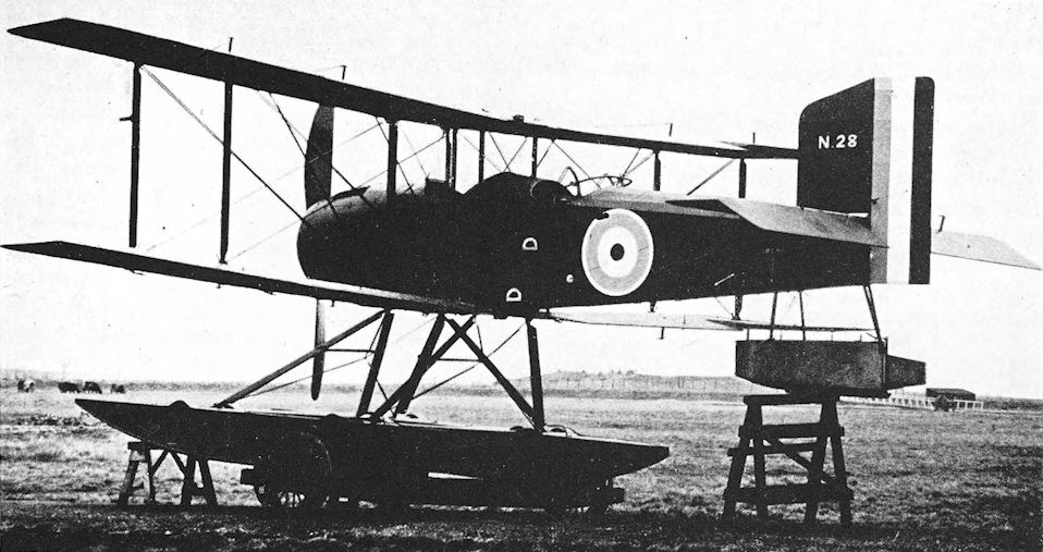
The second R/200, N28, at Grain in December 1917.
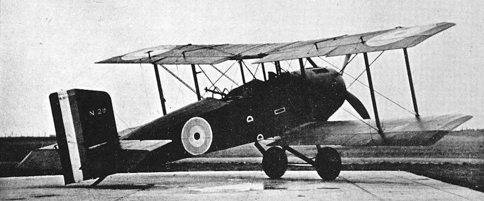
Handley Page R/200 landplane, N.29.
Handley Page V/1500
IT has already been told, in the history of the Handley Page O/400, how the V/1500 was ordered as an experimental bomber after the meeting of the Air Board which was held on July 30th, 1917. A factor which influenced the design was the expectation that hostilities would continue until well into 1919 at least, and the machine had to be capable of taking a worthwhile bomb-load from bases in England to Berlin and other enemy industrial centres.
The V/1500 was therefore necessarily a large aeroplane, larger, in fact, than any which had been built in Britain up to that time. It was not quite so large as some of the contemporary German Riesenflugzeuge (Giant aeroplanes), but was a much more workmanlike aircraft and a good deal simpler structurally than any of the enemy types.
The huge airframe embodied all the experience gained in the construction of the O/100 and O/400. The fuselage of the V/1500 was made in three sections. The front section was built mainly of silver spruce, and was covered with plywood for a distance of seven feet from the nose. The centre portion contained the bomb-bay, and was built wholly of spruce apart from two cross beams in the bomb-bay, which were of ash. The upper half of the centre portion was occupied by the main fuel tank; below it the bomb-racks were fitted. The rear portion of the fuselage was constructed of McGruer circular spruce sections, and there was a cat-walk which extended to the gunner’s cockpit in the extreme tail of the aircraft. The whole fuselage was a cross-braced box girder.
The upper mainplanes were built in five sections, the lower in six; despite their great size the wings could be folded. Silver spruce box spars were used, and the compression struts were either box-type structures or of the McGruer tubular type; the ribs were of silver spruce, and cross-bracing was by tie-rods. The ailerons had solid spars; they and the aileron ribs were made of silver spruce. The upper centresection contained four water tanks and two gravity tanks for petrol; the latter were each divided into two compartments. The interplane struts were built up of wood, whilst the struts supporting the engine-bearers were of steel tube, as were the bearers themselves.
Late in 1917, the Rolls-Royce company began work on the design of a new engine which was intended to be the power-unit of the V/1500. This was the Condor, which was virtually a considerably enlarged Eagle: the bigger engine had a modified cylinder head design, four valves per cylinder instead of the Eagle’s two, and correspondingly revised valve gear. The first experimental Condors delivered 600 h.p. and would have been ideal for the V/1500. However, they were not ready until early 1919, and it was necessary to instal other engines in the aircraft. Four Rolls-Royce Eagles were fitted, mounted midway between the wings in two tandem pairs. The tractor engine on each side drove a two-bladed airscrew, and the pusher drove a four-blader of smaller diameter. There was one oil feed tank to each pair of engines, situated above the forward power-unit.
The tail-unit was a biplane structure with four vertical surfaces. The tailplane leading edges and spars were solid spruce, as were the elevator spars; the elevator trailing edges were of steel tube.
The undercarriage was necessarily substantial yet structurally simple: there were two twin-wheel units, and the front leg of each vee incorporated an oleo shock absorber. Each wheel was 5 feet in diameter. The massive tail-skid was made of solid ash, and was sprung by rubber shock-absorber cord.
The components of the prototype V/1500 were made in great secrecy by Messrs Harland & Wolff at Belfast. This firm’s first contract for twenty V/1500s was dated January 27th, 1918, and it appears that the aircraft was more or less ordered off the drawing-board, for the prototype did not fly until May, 1918. If this were so, it was a remarkable act of faith on the part of the Air Board.
The prototype V/1500 had several features which were not perpetuated in production machines. The most obvious of these was the large single radiator, mounted on top of the fuselage in front of the forward centre-section struts: this radiator served all four motors. At this time the engines had no cowlings of any kind.
The ailerons had triangular inset horn balances. The tailplanes had a rather narrow gap; there were no fixed fins; and all four rudders were balanced surfaces pivoted on the front spars of the tailplanes. Inter-tailplane struts were fitted between the rear spars.
The first flight of the V/1500 took place in May, 1918, when the prototype was flown by Captain Busby, R.F.C. His crew consisted of F. A. Kappey and Mr Hathaway. The flight was made from Cricklewood, and was followed by several further test flights during the next few weeks.
Control response was not completely satisfactory, and various modifications were made during the course of these flights. The original horn-balanced ailerons were replaced by surfaces with set-back hinges; and a little later the balance areas of the rudders were reduced by removing an area of fabric from each.
Directional control was still unsatisfactory, and the fin area was increased by fitting a single rectangular surface above the upper tailplane and by adding a long pointed fairing to the extreme tail of the fuselage. Ultimately, a drastically revised tail-unit was fitted: it had a greatly increased gap to enable enlarged vertical surfaces to be fitted. Inter-tailplane struts were fitted between the front spars of the tailplanes, and immediately behind these struts were four substantial fins; each fin carried a plain unbalanced rudder.
Modifications to other parts of the machine were also made concurrently. When the ailerons were changed, the large central radiator was replaced by two tall upright radiators, one at the front of each pair of engines; by this time the engines had been enclosed in rather bulky nacelles. The foremost portion of fuselage-decking was removed and the nose gun position was made.
By the time the final form of tail-unit was fitted, the engine cowlings had been discarded and only their framework remained.
The prototype V/1500 made its last flight in June, 1918. Captain Busby and Hathaway took four passengers, one of whom (Colonel Ogilvie) occupied the gunner’s cockpit in the extreme tail. On this flight the machine crashed and was completely burnt out. Colonel Ogilvie alone survived because of his remote position.
Development was delayed until a second machine - almost certainly the first production V/1500 - became available in October, 1918.
In the production aircraft the engine cowlings were completely discarded. It was found that 500 lb of weight was saved, and performance suffered very little. Hexagonal radiators were fitted in place of the tall rectangular radiators of the prototype. Scarff ring-mountings were fitted to the cockpits in the extreme nose and tail of the fuselage; the latter defensive position was pioneered by the V/1500. There was a third gunner’s position on top of the fuselage just behind the wings.
The Air Ministry’s first provisional expansion programme for the Independent Force was forwarded to the Admiralty and War Office on June 20th, 1918. This envisaged a total of 340 Service squadrons by the end of September, 1918. Of that total, sixty squadrons were to be with the Independent Force, forty in France and twenty night bomber squadrons based in England. Thus was born a new conception of bombing technique, made possible by the potentialities of the Handley Page V/1500.
The expansion programme underwent several changes, until by the end of October the English-based squadrons of the Independent Force had been reduced to eight.
The English-based bombing force was to operate under the command of Major-General Trenchard, and No. 27 Group began to organise early in September, 1918, under Lieutenant-Colonel R. H. Mulock at Bircham Newton, Norfolk. It was to consist of the 86th and 87th Wings, and it was intended that the former should operate from England and that the latter should go to France after formation.
The first squadron of No. 27 Group to be mobilised was No. 166. The crews for the squadron’s V/1500s were carefully selected, many of them seasoned pilots and observers from the night-bombing F.E.2b squadrons. To them, their aircraft were known as super-Handley Pages or super-Handleys.
But of the total of 255 super-Handleys which had been ordered, only three were ready for use at the time of the Armistice, and the V/1500’s capabilities remained untested, its ability to carry the war to the enemy’s capital unexploited. Had it gone into large-scale service both in France and in England it would have been a weapon to reckon with, for on shorter raids it could carry no fewer than thirty 250-lb bombs or their equivalent weight. The bomb load for a Norfolk-Berlin raid could hardly have exceeded 1,000 lb, but by late 1918 Britain had a 3,300-lb bomb which was intended for use with the V/1500.
For the V/1500s ordered from the Beardmore Company, four of the 500 h.p. Galloway Atlantic engines were specified. The Napier Lion.was another alternative power unit for the aircraft, and four Liberty engines were to have been tried.
After the Armistice the big Handley Page saw little service. The immediate economies of the postwar world favoured the smaller and less complicated Vickers Vimy.
Before the end of 1918 a V/1500 named H.M.A. Carthusian took off from Martlesham to commence the first through flight from England to India. The flight began on December 13th, 1918, and ended, after many vicissitudes, on December 30th, when the V/1500 landed at Karachi after flying the last 35 miles just above stalling speed with only two engines functioning. The V/1500 was flown by Major A. S. C. Maclaren, M.C., and Captain Robert Halley, D.F.C., accompanied by Brigadier-General N. D. K. McEwen and three mechanics.
This V/1500 was probably the only aeroplane of its type to drop bombs with lethal intent. The Afghan war had broken out, and it was desired to attack Kabul. It was originally intended that the raid should be made by the Handley Page O/400 which had been attached to No. 1 Squadron of the Australian Flying Corps, for it was thought that the fully loaded V/1500 might not be able to climb high enough to clear the Pathan Hills. When the O/400 was wrecked in a cyclone, however, the V/1500 had to be used, and Captain Halley successfully took it to Kabul, dropped his bombs, and returned safely.
Another V/1500 was shipped to Newfoundland in 1919 to attempt the trans-Atlantic flight, but was forestalled by Alcock and Brown’s crossing in a Vimy.
At home, the V/1500 demonstrated its weight-lifting capabilities and its long range on several occasions. On November 15th, 1918, one took its pilot and forty passengers to nearly 6,500 feet over London with enough fuel on board for a six-hour flight. Several notable long-distance flights were made by the V/1500; the pilot on these occasions was Clifford B. Prodger. However, the type was too expensive an aircraft for the nascent air transport industry, and it found no lasting commercial application.
As an aeroplane, the V/1500 must be recognised as one of the finest achievements of the British aircraft industry during the war, and it initiated a bombing plan which, a quarter of a century later, was translated into action by its lineal descendant, the Halifax.
SPECIFICATION
Manufacturers: Handley Page, Ltd., Cricklewood, London.
Other Contractors: William Beardmore & Co., Ltd., Dalmuir, Dunbartonshire; Harland & Wolff, Ltd., Belfast.
Power: Four 375 h.p. Rolls-Royce Eagle VIII; four 500 h.p. Galloway Atlantic; four 450 h.p. Napier Lion; four 400 h.p. Liberty 12.
Dimensions: Span: 126ft. Length: 62 ft. Height: 23 ft. Chord: 12 ft. Gap: maximum 15 ft, minimum 12ft. Stagger: nil at centre-section, 2-5 in. at outer struts. Dihedral: upper, nil; lower 40 05'. Incidence: 40. Airscrew diameter: tractor 13 ft 5 in., pusher 10 ft 4 in.
Areas: Wings: 3,000 ft.
Weights (lb) and Performance:
No. of Trial Report M.228 M.256
Date of Trial Report September, 1918 May, 1919
Types of airscrew used on trial - A.B.8420, A.B.8501
Weight empty 16,210 17,602
Military load 3,120 80
Crew 1,080 1,080
Fuel and oil 4.290 5.3i8
Weight loaded 24,700 24,080
Maximum speed (m.p.h.) at
6,500 ft - 90-5
8,750 ft 97 -
10,000 ft - 855
m. s. m. s.
Climb to
6,500 ft 18 30 21 05
10,000 ft - - 41 25
Service ceiling (feet) 10,000 11,000
Endurance with quoted fuel load - 6 hours
Maximum endurance - 14 hours
Tankage: Petrol: 1,000 gallons.
Armament: One Lewis machine-gun, or double-yoked pair, on Scarff ring-mounting on nose cockpit; one Lewis gun on central socket and pillar mounting, or two Lewis guns on beam socket and pillar mountings in dorsal gunner’s position; one Lewis gun on Scarff ring-mounting on tail cockpit. The bomb load could consist of up to thirty 250-lb bombs.
Service Use: No. 166 Squadron, R.A.F., Bircham Newton. Production: A total of 255 Handley Page V/1500s were ordered, but only six had been delivered by the end of 1918. On October 31st, 1918, only two were on charge with the R.A.F.; both were at an experimental station.
Serial Numbers:
Serial Nos. Contractor Contract No. Specified Engines
B.9463-B.9465 Handley Page A.S.22690 Eagles
E.4304-E.4323 Harland & Wolff 35A/I85/C.74 Eagles
E.8287-E.8306 Beardmore 35A/315/C.200 Atlantics
F.7134-F.7143 Handley Page 35A/1455/C.1528 -
F.8201-F.8230 Handley Page - -
F.8281-F.8320 Handley Page - -
H.4825-H.4864 Handley Page - -
J.6523-J.6572 Handley Page - -
Costs:
Airframe without engines, instruments and guns £12,500 0s.
Rolls-Royce Eagle VIII engine (each) £1,622 10s.
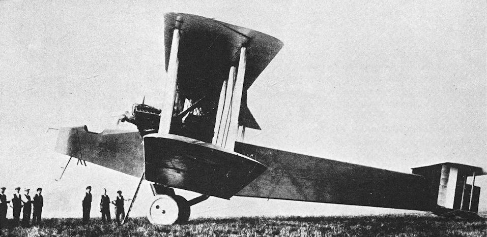
Handley Page V/1500. The prototype V/1500 in its original form. Note the horn-balanced ailerons and narrow-gap tail-unit.
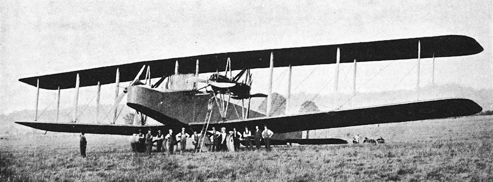
Handley Page V/1500. Another view of the prototype in its original form. This photograph shows the large single central radiator above the fuselage.
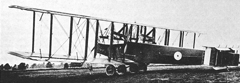
Handley Page V/1500. The prototype fitted with engine cowlings; the fabric has been removed from the balance areas of the rudders; modified ailerons fitted.
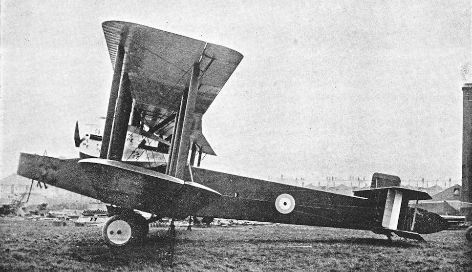
Handley Page V/1500. The prototype B9464 at Cricklewood with extended stern fairing and additional fin above upper tailplane in September 1918.
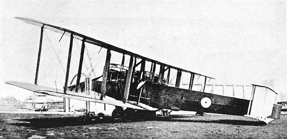
Handley Page V/1500. The prototype with engine cowlings removed and production-type tail-unit fitted.
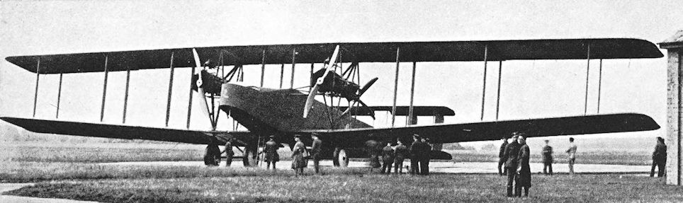
Stated in some works to be a Cricklewood-built V/1500, this aircraft is of the finite production standard, with symmetric hexagonal frontal radiators and tailplanes with increased gap; note the two-blade tractor propellers and the four-blade pushers of reduced diameter.
Hoile Varioplane
THE name of A. A. Hoile (who was a Dutchman) is probably best remembered as the designer of the peculiar cantilever monoplane wing which, in 1921, was fitted to the fuselage of the little Martinsyde Semiquaver racer. The wing was known as the Alula wing.
The unusual plan-form of that ultimate Alula wing had two antecedents, the second of which did not appear until after the war. The first was flown on a little monoplane which was far ahead of its time in one respect. This machine was a parasol monoplane known as the Varioplane, and was powered by a 60 h.p. six-cylinder Anzani radial engine. It was flown in 1917.
Structurally the fuselage and tail surfaces were quite conventional, as the illustration shows, but the wing was a most striking affair. It had a swept-back leading edge and curved wing-tips which tapered to a sharp point. For a considerable part of its span, outboard of the lift-struts, the wing was a cantilever and looked far from safe.
Most remarkable of all, however - and obviously the aircraft’s raison d’etre - was the use of a variable camber device which closely resembled the split trailing-edge flaps which did not come into general use until nearly twenty years later. It will be seen that the fabric covering of the underside of the Varioplane’s wing was continuous from leading edge to trailing edge, and drooped with the “flaps”. The trailing edge was split, but the upper surface of the variable camber portion drooped in company with the lower.
Hoile flew his Varioplane at Brooklands, and the machine later went to Farnborough to be tested.

Hoile Varioplane.
Kennedy Giant
IT has been said that Chessborough J. H. Mackenzie-Kennedy was the man who took aviation to Russia. At the age of eighteen he went there with three pounds in cash and a strong belief in the possibilities of aviation. He went to the Putiloff Gun Works and discussed his plans to such good purpose that he almost immediately became a member of the Imperial Russian Technical Society and was given a good deal of support.
By 1908 he had completed the design of the first Russian aeroplane, and in the following year he formed the Kennedy Aeronautic Company. In 1911 he met Igor Sikorskii, and the two became friends. Both were convinced of the practicability and usefulness of very large aeroplanes, and in 1913 there appeared the first Sikorskii four-engined biplane, with the design of which Kennedy had been associated.
Soon after the outbreak of war Kennedy returned to Britain. The success of the big Sikorskii machines had fired his enthusiasm afresh, and he forthwith took his own ideas for a giant aeroplane to the War Office. He was rewarded with permission to construct a prototype, and set up his design office at 102 Cromwell Road, South Kensington. Associated with him were T. W. K. Clarke, who had been one of the pioneers of aviation in Britain, E. A. Vessey and G. C. McClaughlin.
The construction of the Kennedy Giant was undertaken by the Gramophone Company, Ltd., and the Fairey Aviation Company, Ltd., both of Hayes, Middlesex. The completed components were sent to Northolt aerodrome for assembly towards the end of 1916, but the machine was so large that it had to be erected in the open: there was no hangar large enough to accommodate it.
In appearance the Kennedy Giant bore a general resemblance to the Sikorskii Ilya Mourom’etz. The deep and commodious fuselage provided completely enclosed accommodation for the crew: the pilot sat in the extreme nose, and behind his compartment were a navigation room and other cabins. Windows were fitted along the entire length of the fuselage.
The completion of the Giant was not accomplished without incident. The surviving accounts contain the elements of conflict and confusion, and doubtless the passing of time has blurred the details. One account says that when the first attempt to move the Giant was made, it needed the combined efforts of two lorries and seventy men to haul it along. These exertions proved too much for the machine, for it broke its back. The fuselage was shortened by about ten feet and repaired, and construction proceeded.
It has also been recorded that the mainplanes had to be moved aft by an appreciable distance during the erection of the aircraft; assembly was thereby delayed.
Structurally the Giant was more or less conventional. The fuselage was a cross-braced box girder of almost constant depth, and terminated in a rudder which could hardly have been adequate even if the fuselage had been longer or the mainplanes farther forward. It looked absurdly small on the completed machine, but was later replaced by a very much larger horn-balanced rudder; the original plain elevators were also replaced by horn-balanced surfaces.
Ailerons were fitted to the upper wings only, and were actuated by long spanwise shafts which ran along the wing just above the leading edge. A similar control system operated the elevators. The undercarriage was a wonderfully complicated affair which had four wheels and a multiplicity of struts.
Unfortunately for Kennedy, the only engines which the authorities would release for his machine were some British-built Salmson water-cooled radials of 200 h.p. each. The serial numbers of these engines indicate that they were among the first Salmsons to be made by the Dudbridge Iron Works, Ltd., who held the British licence for their manufacture.
The engines were mounted above the lower wing in two tandem pairs, and each engine had two radiators, one on either side. The intention was that these engines should be cleanly cowled, for large pointed spinners were later fitted to the pusher airscrews. With only 800 h.p. available the Giant was badly underpowered.
The first attempts to fly the aircraft were made late in 1917 by Lieutenant Frank T. Courtney, who was then an instructor with No. 35 Training Squadron at Northolt. After several attempts had proved unsuccessful, Courtney taxied at full throttle down a slight slope from the hangars against a stiff breeze, but even that rather desperate action resulted in no more than a straight hop with the wheels off the ground but with the tail-skid trailing.
No further attempts were made to fly the Giant. For want of sufficiently powerful engines it was never properly completed, and lay derelict at Northolt for several years. Kennedy retained his faith in large aeroplanes, for in 1919-20 a second Giant of his design was under construction at the Victoria Works of John Dawson & Company, Ltd., Newcastle-on-Tyne. This was to have been smaller than its predecessor: the span was to have been too feet, the length 55 feet, and the estimated useful load was 6,500 lb. Better luck with engines was obviously hoped for: the estimated maximum speed of the second Giant was 120 m.p.h. Kennedy’s venture failed financially in December, 1920, however, and his new aircraft was never completed.
SPECIFICATION
Manufacturers: Kennedy Aeroplanes, Ltd., 102 Cromwell Road, South Kensington, London, W.7. Components made by the Gramophone Company Ltd., Hayes, Middlesex, and by the Fairey Aviation Company, Ltd., Hayes.
Power: Four 200 h.p. Salmson, engines numbered 2, 6, 8 and 10.
Dimensions: Span: 142 ft. Length: 80 ft. Height: 23 ft 6 in. Chord: 10 ft. Gap: 10 ft.
Weights: Empty: 19,000 lb.
Serial Number: 2337.

Kennedy Giant. The Giant when first completed, with its original small rudder.

The Giant with enlarged rudder and modified elevators.
Lakes Flying Co. (later N.A.C.) Monoplane
BY the end of 1912 the Lakes Flying Co. found that the Water Hen was no longer able to cope on its own with the growing demands for pleasure flights. The company therefore commissioned O. T. Gnosspelius to design a new floatplane for use on Lake Windermere.
Mr Gnosspelius had designed a little monoplane with a broad-beamed central float in 1911. With it he had attempted a flight shortly before the Water Hen first flew, but the Gnosspelius machine was overturned by a gust of wind just as it took off. It was later successfully flown on February 13th, 1912.
Mr Gnosspelius had an original turn of mind, and the new floatplane that he designed for the Lakes Flying Co. was almost unique, for it was a pusher monoplane. The machine was built by Borwick & Sons of Bowness.
The monoplane wing was mounted at the level of the upper longerons of the boat-shaped nacelle. An 80 h.p. Gnome engine was fitted at the stern of the nacelle. There were four tail-booms: the upper pair were attached to the wing, the lower pair to the undercarriage bracing system. The wings were braced by cables; landing loads were taken by cables running from a double cabane system.
The original undercarriage consisted of a large central float, with outboard floats for stability. A small tail float was also fitted.
The monoplane was taken over by the Northern Aircraft Co. in 1914; thereafter it was usually referred to as the N.A.C. hydro-monoplane. Like the Water Hen, it was later given a twin-float undercarriage with two single-step pontoon-type floats. When these were fitted the outboard floats were removed.
After the outbreak of war, the monoplane shared with the Water Hen the duty of training seaplane pilots for the R.N.A.S., and was used in that capacity until 1916.
SPECIFICATION
Manufacturers: Built by Berwick & Sons, Bowness-on-Windermere, for the Lakes Flying Co.
Power: 80 h.p. Gnome.

Lakes Flying Co. Monoplane. The monoplane with its original centre-float undercarriage.
Mr. W. Rowland Ding on the monoplane just off the surface of Lake Windermere.
Mr. W. Rowland Ding on the monoplane just off the surface of Lake Windermere.
Lakes Flying Go. (later N.A.G.) Water Hen
CAPTAIN E. W. WAKEFIELD was one of the little-known pioneers of aviation in England. As early as 1909 he publicly expressed his belief that, in the state of aeronautical knowledge at that time, the best type of aircraft to develop would be one capable of rising from and alighting on water. Such a machine, he argued, would be less susceptible to the type of damage so frequently sustained by contemporary aeroplanes.
Wakefield’s ideas were scorned, but his faith in the seaplane was soon vindicated by the successful flights made by Henri Fabre’s “hydro-aeroplane” at Monaco and, later, by Glenn Curtiss in America. The Curtiss aircraft was a biplane fitted with a central-float undercarriage.
Captain Wakefield and a few friends formed the Lakes Flying Co. in 1911 and commissioned A. V. Roe to build a centre-float seaplane generally similar to the Curtiss machine. The aeroplane which was built against this order was known as the Waterbird, and had a single narrow float mounted centrally. Although reasonably efficient, the Waterbird did not come up to expectations: it was flying in November, 1911, and had the distinction of being the first successful British aircraft to be designed as a floatplane from the beginning.
Meantime, representatives of the Lakes Flying Co. had been studying developments in the design and construction of aeroplanes. They applied their knowledge to the design of a new floatplane, which was completed by the spring of 1912.
The new aircraft was named Water Hen. It was an unequal-span pusher biplane with both front and rear elevators; the engine was a 50 h.p. Gnome rotary. The first float to be fitted to the Water Hen was 12 feet long and 6 feet in beam, and was made by Borwick & Sons, a firm of boat-builders of Bowness-on-Windermere. It was made of mahogany and canvas, and had three steps. An improved single-step float was later fitted; it had silver spruce frames and three longitudinal bulkheads. The planing bottom was covered with aluminium, the sides with duralumin, and the top with Willesden canvas. The float was connected to its attachment frame by means of rubber cord. Stability on the water was ensured by two small air sacks, one mounted under each lower wing.
The Water Hen was designed to be a slow-flying aircraft, for it was intended to have a low take-off speed and to be able to lift a passenger easily. The passenger sat high up between the wings, and the pilot’s seat was lower down, immediately in front of the lower wing. There was no protection of any kind for either occupant.
The aircraft was an instant success, and its basic design was little altered throughout its long career. The fitting of the improved float has been mentioned, and subsequent modifications were of a similar nature.
The Water Hen was used at Lake Windermere as a joy-riding machine, and flew with a regularity which was outstanding for the time. By the beginning of December, 1912, it had made 250 flights and had carried 100 passengers during the seven months it had been in existence.
The Water Hen was still flying when war broke out, by which time it had been modified by the addition of a small nacelle to protect the pilot and passenger, whose seats had been suitably re-aligned; and the big central-float had been replaced by two separate pontoon-type floats. When this last modification was made the wing-tip floats were removed.
The Lakes Flying Co. was succeeded by the Northern Aircraft Co., who continued to operate the Water Hen. A number of R.N.A.S. seaplane pilots received their initial instruction on this veteran seaplane, which continued to fly until 1916 as if in vindication of Captain Wakefield’s belief in the usefulness and safety of floatplanes.
SPECIFICATION
Manufacturers: The Lakes Flying Co., Cockshott, Windermere (float made by Borwick & Sons, Bowness-on-Windermere).
Power: 50 h.p. Gnome.
Dimensions: Span: upper 42 ft, lower 32 ft. Length: 36 ft 5 in. Chord: 5 ft. Gap: 5 ft. Stagger: nil. Span of tail: 6 ft 10 in. Span of forward elevator: 6 ft 10 in. Airscrew diameter: 8 ft 6 in.
Areas: Wings: 365 sq ft. Tailplane: 11 sq ft. Elevators: rear 6-5 sq ft, front 17-5 sq ft. Rudder: 9-5 sq ft.
Weights: Empty: 780 lb. Loaded: 1,130 lb.
Performance: Maximum speed: 45 m.p.h. Ceiling: 800 ft.
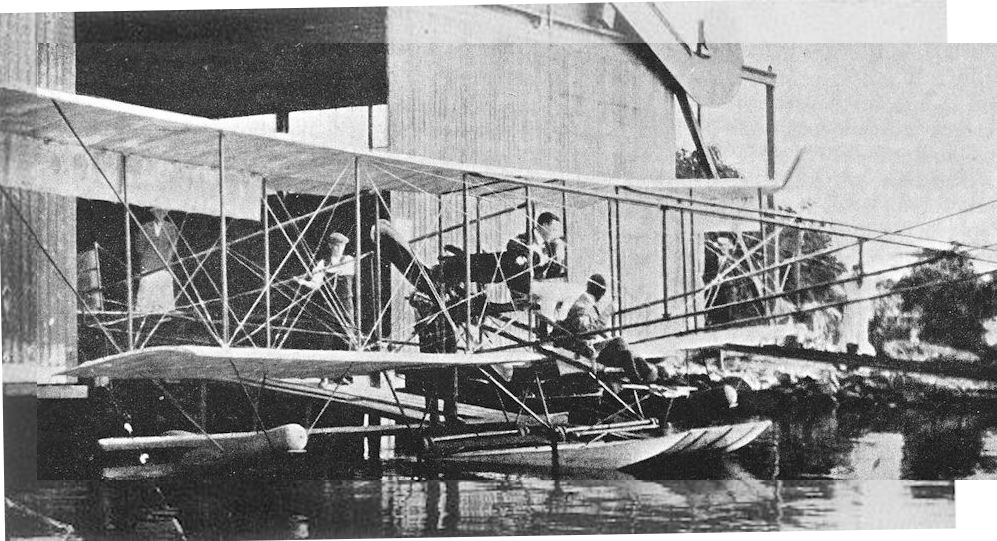
Lakes Waterhen was a modified copy of the Waterbird built by the Lakes company at Windermere in 1912. Shown here at an early stage with wide central-float and exposed crew.
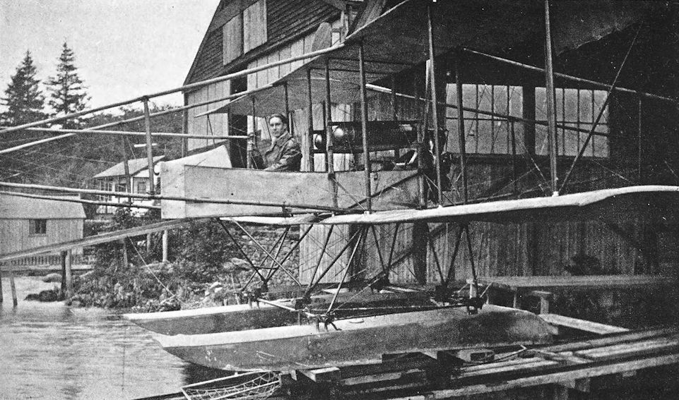
The modified Water Hen with twin-floats and nacelle.
London and Provincial School Biplane Type No. 4
THE London and Provincial Aviation Co. operated a flying school at Hendon aerodrome from 1914 onwards. The company built some training machines of the Caudron type for use at their school.
In 1916, A. A. Fletcher left the Martinsyde concern to join the London and Provincial company, and he designed two trainer aircraft for his new firm. The first of these was a small and thoroughly conventional little two-bay biplane, powered by a 50 h.p. Gnome rotary engine, and known as the London and Provincial Type No. 4.
The London and Provincial concern later moved to their own aerodrome at Edgware, and it was there that the machine was flown.
After the Armistice, the London and Provincial company tried to market the little Gnome-powered biplane as a cheap aeroplane powered by an engine which was easily obtainable. Unfortunately, the Gnome’s lack of dual ignition led to the A.I.D.’s refusal to approve the aircraft, and production could not be undertaken.
SPECIFICATION
Manufacturers: The London and Provincial Aviation Co., Edgware, London, N.
Power: 50 h.p. Gnome.
Dimensions: Span: 32 ft 6 in. Length: 25 ft 3 in. Height: 8 ft gin. Chord: 4 ft 74 in. Gap: 5 ft. Span of tail: 10 ft 6 in. Airscrew diameter: 7 ft.
Areas: .Wings: 280 sq ft. Ailerons: each 10 sq ft, total 40 sq ft. Tailplane: 24-75 sq ft. Elevators: 16-25 sq ft. Fin: 3 sq ft. Rudder: 6 sq ft.
Weights: Empty: 655 lb. Loaded: 1,070 lb.
Performance: Maximum speed at ground level: 60 m.p.h. Climb to 5,000 ft: 20 min. Endurance: 11 1/2 hours.
Tankage: Petrol: 8 gallons. Oil: 4 gallons.
London and Provincial School Biplane
DEVELOPED from the Gnome-powered London and Provincial Type No. 4 was the larger two-seater with the 80 h.p. Anzani radial engine: it appeared in the middle of 1916. The later machine displayed several characteristics which combined to produce a certain likeness to Fletcher’s earlier design, the Martinsyde Elephant.
In construction, the Anzani-powered London and Provincial biplane was typical of its period. The fuselage was basically of rectangular section with ash longerons; the forward portion had diagonal spruce struts for bracing and was covered with ash plywood, and the rear portion was cross-braced by wire in conventional fashion. A rounded top-decking was fitted.
The equal-span wings were also of wooden construction and had sharply-raked tips: ailerons were fitted to upper and lower mainplanes. The tail surfaces were of generous area and conventional construction. The undercarriage was a simple vee structure consisting of two faired steel tube vees connected by two steel tube spreader-bars between which the axle lay. The wheel track was unusually wide, presumably to ensure ground stability in an aeroplane intended for use as a trainer.
The type was built in small numbers by the London and Provincial Aviation Co. for use at their own school, and the machine proved to have good flying qualities. It was quite manoeuvrable, and in the hands of G. Smiles set up a number of looping records at Hendon in 1916.
For experimental purposes, one of the London and Provincial machines was flown with a set of S.E.5 mainplanes strapped to the underside of its own lower wings. Presumably this was done to test the feasibility of transporting spares in this way; it is recorded that the London and Provincial biplane flew satisfactorily with its unusual load.
Later, the type was used in parachute experiments, and many jumps were made with “Guardian Angel” Parachutes. On July 10th, 1918, W. L. Wade, wearing one of these parachutes, made a live drop from an L. and P. Anzani biplane flying at 400 feet. The aeroplane was flown by Captain R. Payze, R.A.F.
Five London and Provincial biplanes came on to the British Civil Register after the Armistice. The machine which became G-EAQW was fitted with a 100 h.p. Anzani instead of the original 80 h.p. engine.
SPECIFICATION
Manufacturers: The London and Provincial Aviation Co., Edgware, London, N.
Power: 80 h.p. Anzani; 100 h.p. Anzani.
Dimensions: Span: 37 ft. Length: 25 ft. Chord: 5 ft. Gap: 5 ft. Dihedral: 1° 30'. Span of tail: 12 ft 10 in. Wheel track: 7 ft. Airscrew diameter: 8 ft.
Areas: Wings: 350 sq ft. Ailerons: each 14 sq ft, total 56 sq ft. Tailplane: 36 sq ft. Elevators: 19 sq ft. Fin: 6 sq ft. Rudder: 9 sq ft.
Weights (with 80 h.p. Anzani): Loaded: 1,400 lb.
Performance: Endurance: 3 hours.

London & Provincial Biplane Type No. 4.

Three-quarter front view of the London & Provincial School Biplane
Mann, Egerton Type B
THE well-known motor-car building firm of Mann, Egerton & Co., Ltd., placed their manufacturing resources at the disposal of the Admiralty in the spring of 1915. The response to this offer was an official request that the company should build seaplanes. The first type of aircraft to be produced was the Short Seaplane Type 184, for which Mann, Egerton & Co. were among the earliest contractors. The firm regarded the Short 184 as their own Type A.
While the Shorts were in production, the company were asked to assist in the design of a seaplane very similar to the Short 184 but intended to be an improved type. The modified aircraft, designated Type B by Mann, Egerton & Co., incorporated a large number of standard Short 184 components, but differed markedly in having wings of unequal span. There were two bays of interplane bracing, but the upper wings had enormous extensions which were liberally braced by cables; there were tall king-posts above the outer interplane struts. Each upper wing was made in two sections which met immediately outboard of the king-posts. The outer sections carried the ailerons, which were inversely tapered. No ailerons were fitted to the lower wings. The wings could be folded, and slinging gear was fitted above the centre-section.
The fuselage, tail-unit and undercarriage appeared to be standard Short 184 components. The 225 h.p. Sunbeam engine was fitted, but was mounted a few inches higher than in the Short. Consequently the nose lines of the Mann, Egerton Type B were slightly different, and the top decking behind the radiator sloped downwards to the pilot’s cockpit.
Only ten aircraft of the type were built and were delivered in 1916. They were used by the R.N. A.S. for patrol duties, in company with standard Short 184s.
SPECIFICATION
Manufacturers: Mann, Egerton & Co., Ltd., Prince of Wales Road, Norwich.
Power: 225 h.p. Sunbeam.
Armament: One Lewis machine-gun in observer’s cockpit. Bombs could be carried on racks under the fuselage.
Service Use: R.N.A.S. Seaplane Station, Calshot.
Production: Ten Mann, Egerton Type B seaplanes were built.
Serial Numbers: 9085-9094.

Mann, Egerton Type B. This illustration shows aircraft No. 9085.
Mann, Egerton H.1 and H.2
AFTER the Type B seaplane, production of aircraft by Mann, Egerton & Co. continued with the construction of a batch of Short Bombers, designated Type C (with short fuselage) and Type CA (with long fuselage) by the firm. These were followed by the Sopwith 1 1/2-Strutter, of which the two-seat version was named Type D and the single-seat bomber version Type E. Type F was to have been an aeroplane wholly designed by Mann, Egerton & Co., but its construction was abandoned when the firm were urgently called upon to produce the French Spad S.7 in quantity: the Spad was named Mann, Egerton Type G.
In 1917 the company completed an aeroplane which was entirely of their own design. It was a singleseat fighter for shipboard use, and was designated Type H; it was officially regarded as appropriate to the Admiralty category N.1A. The design work had been done by J. W. Carr. The Type H existed in two different forms; both were powered by a 200 h.p. Hispano-Suiza engine. The first machine, N.44, was known as the Mann, Egerton H.1; and it seems probable that it was designed to the same specification as the Beardmore W.B.IV, for permanent flotation gear was very much in evidence on both aircraft. The Mann, Egerton H.1 was more conventional than the Beardmore, however, and relied upon a wholly external buoyancy chamber to keep it afloat in an emergency; there were additional buoyancy chambers in the rear of the fuselage. The external float attachment ran along the underside of the fuselage from the nose to a point below the cockpit. The undercarriage could be jettisoned before alighting on the water, and wing-tip floats were provided to maintain stability when afloat.
The two-bay wings could be folded, and there was a slinging attachment above the centre-section. The aileron control cable ran out from the fuselage along the lower wing, over a pulley mounted externally on the rear spar of the lower wing, and then up to the upper aileron. The upper and lower ailerons were interconnected by struts.
The initial test flights of the Mann, Egerton H.1 were made by Clifford B. Prodger, and it underwent its official trials in October, 1917. It flew well, was said to manoeuvre well and land easily, and was considered suitable for night flying. It failed to pass the flotation test, however.
The second aircraft, N.45, differed from the first in having no fixed buoyancy chambers. Instead, it was fitted with inflatable air bags of balloon fabric, which could be trimmed by means of a hand pump. This second machine was known as the Mann, Egerton H.2, and its airframe was basically identical to that of N.44. The later aircraft had a larger horn-balanced rudder, and its exhaust pipes were shorter. The H.2 was tested in December, 1917, and was flown at the Isle of Grain.
Mann, Egerton & Co. built no more aeroplanes of their own design. Until the Armistice, their manufacturing facilities were devoted to the production of the D.H.9 (Mann, Egerton Type J), D.H.9A (Type M), and D.H.10 Amiens (Type N).
SPECIFICATION
Manufacturers: Mann, Egerton & Co., Ltd., Prince of Wales Road, Norwich.
Power: 200 h.p. Hispano-Suiza.
Dimensions: Span: 30 ft 9 in. Length: 21ft 11 in. Height: 8 ft 11 1/2 in. Chord: 5 ft 3 in. Gap: 5 ft. Stagger: nil. Dihedral: nil. Incidence: 2° 30'. Span of tail: 10 ft.
Areas: Wings: 310 sq ft. Ailerons: total 42 sq ft. Tailplane: 18-2 sq ft. Elevators: 17 sq ft. Fin: 4-9 sq ft. Rudder: 7 sq ft.
Weights (lb) and Performance:
Aircraft H.1 with undercarriage H.1 without undercarriage H.2
Date of Trial Report October 14th, 1917 October 14th, 1917 December 4th, 1917
Type of airscrew used on trial A.B.623 A.B.623 A.B.6238
Weight empty 1,838 1,754 1,760
Military load 54 54 61
Pilot 180 180 180
Fuel and oil 332 322 325
Weight loaded 2,404 2,310 2,326
Maximum speed (m.p.h.) at
6,500 ft 100 100 113
10,000 ft 90 90 I 10
15,000 ft - - 103
m. s. m. s. m. s.
Climb to
6,500 ft 9 10 8 20 6 2.5
10,000 ft 18 00 15 30 12 30
15,000 ft - - - - 28 00
Service ceiling (feet) 12,800 14,700 16,800
Endurance (hours) - - 3 1/4
Tankage: Petrol: 40 gallons. Oil: 4 gallons.
Armament: One fixed, forward-firing Vickers machine-gun mounted on top of the fuselage on the port side and synchronised to fire through the airscrew; one Lewis machine-gun on mounting above the centre-section.
Serial Numbers: The numbers N.44-N.49 were allotted for Mann, Egerton single-seat fighters. Only N.44 and N.45, the H.1 and H.2 respectively, were built. They were ordered under Contract No. A.S. 13905/17.

The Mann; Egerton H.1, N44, displaying its large buoyancy chambers under the fuselage and wingtips.
Flush-fitting floats on the first Type H were discarded for the second aircraft.
Flush-fitting floats on the first Type H were discarded for the second aircraft.

Tested at the end of 1917, the Type H (second prototype shown) found no official acceptance.
Mann & Grimmer M.i
IN the years before the outbreak of the 1914-18 war, Reginald Frank Mann made something of a name for himself while still a schoolboy as the designer of some successful model aeroplanes. In 1913, at the age of 16, he went into partnership with his schoolmaster, Robert P. Grimmer, for the manufacture of model aeroplanes on a commercial basis. Both had shared an interest in aviation since 1908.
Even before the outbreak of war, Mann had realised that there would be a need for aeroplanes from which a machine-gun could be fired effectively. One of the more remarkable facts in our aeronautical history is that in 1914 the Edward brothers had patented a synchronising gear to enable guns to be fired through the revolving airscrew of a tractor aeroplane: their patent was No. 23790 A.D. 1914. For some reason best known to the War Office, whence a working model of the gear was sent, no more was heard of the device; our designers were obliged to produce pusher machines such as the D.H.2, F.E.2b, F.E.8 and Vickers F.B.5 in order to provide forward-firing armament; and our pilots were confronted in 1915 by enemy aeroplanes with synchronised machine-guns.
R. F. Mann was aware that, in general, the tractor aeroplanes of the day had a better performance than contemporary pushers, but it was obvious that the frontal airscrew made it impossible, in the absence of any form of synchronising gear, to fit a machine-gun having a forward field of fire. Before the war, Mann and Grimmer had had a desire to produce an aeroplane with twin outboard pusher airscrews, and had secured the interest of W. H. Bonham-Carter in their project.
The outbreak of war made the need for Service aircraft one of urgency. Convinced of the practicability of his ideas, Mann got out his first design drawings in August, 1914. Mr Bonham-Carter provided most of the cash required, and construction of the Mann & Grimmer M.1 began in September, 1914.
Design and construction work were pushed forward at great pressure, in the hope that the M.1 might be used against the enemy early in 1915. Work began in the disused church, which was the workshop, at 7 a.m. each morning and continued until midnight on many nights. The completed components were taken to Hendon at the end of January, 1915, and were assembled early in February.
The basic configuration of the M.1 was that of a two-bay fuselage-type biplane with conventional tail surfaces. The engine installation was quite unlike anything which had been attempted up to that time.
Power was provided by a 100 h.p. Anzani radial engine, which was installed at the forward end of the fuselage. The engine was mounted backwards, and drove a long shaft which passed under the observer’s seat and terminated in a gear-box amidships. From the gear-box, chains drove two outboard pusher airscrews which, with their shafts and sprockets, were mounted on a diamond-shaped system of wires and struts about the inner rear interplane strut on each side. The gear-box was installed to obviate the need for crossing one of the chains to obtain oppositely-rotating airscrews, but imposed a severe weight penalty, for it weighed 100 lb.
The pilot sat well behind the wings, and the observer occupied a seat immediately behind the engine. He therefore had an excellent view forwards and a good field of fire for his Lewis gun.
The undercarriage was originally of the twin-skid type, and the mainplanes had a pronounced taper: the leading edges were swept back.
The first flight of the Mann & Grimmer M.1 was made by Rowland Ding on February 19th, 1915. This was only a short straight hop, but next day he took the machine clear of the aerodrome. He then found that the rudder was not very effective, no doubt because of the absence of slipstream over it, and the throttle jammed at two-thirds open. However, he succeeded in getting back to the aerodrome safely.
The chain transmission behaved in a rather alarming fashion, so a month was spent in attempting to improve its functioning; at the same time a larger rudder and improved airscrews were designed. On March 20th the M.1 reached a speed of 70 m.p.h., a figure which was not bettered on two subsequent flights. The performance fell so far short of Mann’s expectations that he decided to replace the 100 h.p. engine by a 125 h.p. Anzani, and the machine was taken back to Surbiton for modification on April 1st, 1915, after less than one hour’s total flying time.
The new engine required new shafts, sprockets, chains and gear-box. Other modifications included the fitting of a plain vee undercarriage with larger wheels and an even larger rudder, whilst the wires which braced the forward ends of the airscrew shafts were replaced by struts of steel tubes. The stagger was increased, stronger interplane struts were fitted, and new airscrews were installed.
When flown again on June 29th the machine still did not perform well, and other airscrews were fitted in an attempt to improve performance. On July 4th a stay tube broke and shattered the port airscrew, but Ding brought the M.1 down safely. Ding made a number of later flights on the machine, but Sidney Pickles took over the test flying on August 4th.
By August 21st the M.1 was flying quite well: the speed was now 75-80 m.p.h., and the initial rate of climb 500 feet per minute. Unfortunately, the terms of Pickles’ contract with an American firm forbade him to fly machines other than those of his firm’s manufacture, and he had to relinquish the flying of the M.1.
It was not until October 2nd that another pilot was found to fly the Mann & Grimmer machine. He was A. E. Barrs, one of the pre-war Hendon pilots, who had been invalided out of the R.F.C. Barrs made thirty flights on the M.1, some with war load, and reached a height of about 9,000 feet on one occasion. The maximum speed was 85 m.p.h., and its builders claimed that the M.1 was the fastest pusher biplane in existence.
Various refinements were made to improve performance. The stay tubes supporting the airscrew shafts were carefully faired, and at one time the machine was flown with the inner rear interplane strut removed and a fairing fitted over each outboard sprocket and airscrew shaft. A large spinner-like cowling was fitted over what was normally the rear of the engine. By this time the empty weight was some 800 lb greater than it originally was.
On November 16th, 1915, Barrs took off with J. G. Woodley in the passenger’s seat in an attempt to break the British altitude record. About 45 minutes after take-off the M.1 was at a height of between 8,000 and 9,000 feet, and was still climbing well when the gear-box seized. The starboard chain broke and vanished into space, and Barrs switched off and began to glide down. The glide lasted 21 minutes, but near the ground bumpy conditions brought the machine down short of the aerodrome. It ran into some trees and was completely wrecked, though neither occupant was injured in any way.
In its nine months of existence, the M.1 flew for no more than 18 hours, but its builders felt that it had ultimately fulfilled their expectations. After its demise they at once set about the construction of a much improved successor, which was known as the M.2. When half finished the new machine had to be abandoned owing to lack of official support.
R. F. Mann joined the Army, but within a month contracted a severe cold which ultimately developed into tuberculosis. He was invalided out, and died in Rhodesia some years later.
SPECIFICATION
Manufacturers: Messrs Marin & Grimmer, Surbiton, Surrey.
Power: 100 h.p. Anzani; 125 h.p. Anzani.
Dimensions: Span: 34 ft 9 in. Length: 26 ft 5 in. Gap: 5 ft 9 in.
Areas: Wings: 322 sq ft.
Weights: Empty: originally approximately 1,300 lb; in final form about 2,100 lb. Useful load: 700 lb. Weight loaded: approximately 2,800 lb.
Performance: Maximum speed: 85 m.p.h. Initial rate of climb: 500 ft per minute. Climb to 3,000 ft: 8 min. Endurance: 4 1/2 hours.
Armament: One free Lewis machine-gun fired by the observer.
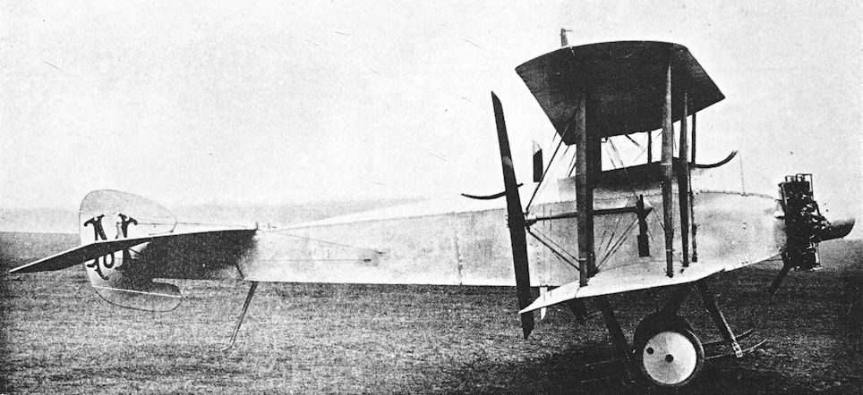
Mann & Grimmer M1 biplane was built at Surbiton in 1914 and was tested at Hendon throughout 1915. Shown here in its original form with skid-type undercarriage, small rudder and light supports for the airscrew shafts.
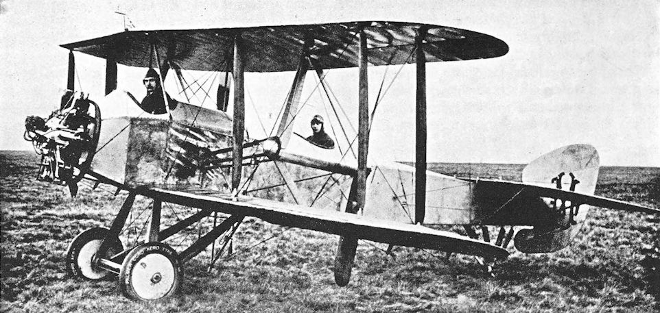
The Mann & Grimmer M.1 in final form with vee undercarriage, propeller shafts braced by struts, larger rudder and inner rear interplane strut removed.
In its definitive form, the M.1 flew for fewer than 20 hrs before it crashed.
In its definitive form, the M.1 flew for fewer than 20 hrs before it crashed.
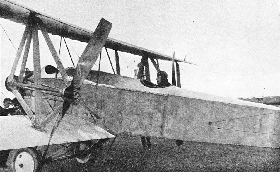
The M.1 in modified form with vee undercarriage and strut-braced supports for airscrew shafts.
Mr. Rowland Ding in the pilot's seat of the Mann biplane, stowing the strengthened bracing of the propeller shaft.
Mr. Rowland Ding in the pilot's seat of the Mann biplane, stowing the strengthened bracing of the propeller shaft.
Martinsyde S.1
BEFORE the outbreak of the first World War, Messrs Martin & Handasyde produced a series of monoplanes, of which the later machines were characterised by great beauty of line. By 1914, however, the Avro 504, Bristol Scout and Sopwith Tabloid had made a great impact on the aeronautical world, for they showed that a carefully designed biplane could out-perform contemporary monoplanes.
The military value of such machines as the Bristol Scout and Sopwith Tabloid was realised in 1914, and the first Martinsyde tractor biplane was a small single-seater in the same general category as the Bristol and Sopwith. (It was not the first Martinsyde biplane, for earlier in 1914 a pusher biplane had been built, powered by a 65 h.p. Antoinette engine.)
The Martinsyde Scout biplane bore the type number S.1, and was powered by an 80 h.p. Gnome engine. It bore a certain resemblance to the Sopwith Tabloid, largely because of the shape of its engine cowling. The fuselage had rather finer lines than that of the Tabloid, however, and terminated in a tail-unit of pleasing outline. The undercarriage was at first a very sturdy structure which had the form of the twin-skid layout then in favour, but a small wheel was fitted at the forward end of each skid. When on the ground the S.1 rested on the rearward extensions of the main skids, and a small bumping skid was fitted under the sternpost of the fuselage.
Later Martinsyde S.1s had a plain vee undercarriage in place of the rather clumsy four-wheel affair, and a normal sprung tail-skid was fitted.
The single-bay wings were conventional in every way, and ailerons were fitted to both upper and lower wings.
The first production S.1s appeared late in 1914: by the end of that year eleven had been delivered to the R.F.C. Some joined the squadrons in France, but they were few in number and no squadron had more than one or two. On March 10th, 1915, No. 4 Squadron had one Martinsyde S.i and No. 5 Squadron had two; two months later, Squadrons Nos. 1, 5 and 6 had one each.
The Martinsyde of No. 6 Squadron was flown by Captain L. A. Strange, and he has recorded that he found it to be “a very unstable machine both fore and aft, with not much aileron control”. He went on to say “Although a single-seater, it was hardly superior in speed and climbing power to the Avro which carried two men, but in my eyes all these defects were outweighed by the fact that it had a Lewis gun mounted on its top plane, which could be fired forwards and upwards.”
That same Lewis gun nearly caused Strange’s death on May 10th, 1915. After emptying a drum of ammunition at an enemy two-seater, he found the drum had jammed. Strange raised himself in his seat and held the stick between his knees in order to have both hands free to work on the drum. He lost his grip on the stick with the Martinsyde in a steep climb; the machine went into an inverted spin and Strange was thrown out, hanging on to the wedged Lewis gun drum. Fortunately the drum did not come off, and he was able to right his aircraft and drop back into his seat after spinning down for more than 5,000 feet.
In addition to its small-scale use on the Western Front, the Martinsyde S.1 also saw service in the Middle East. On August 26th, 1915, four S.1s arrived at Basra to form the equipment of a second flight of No. 30 Squadron. Their Gnome engines were quite unsuitable for work in the heat and dust of Mesopotamia, and constantly gave trouble.
On September 7th, two Martinsydes, a Caudron and a Maurice Farman joined the concentration of the 6th Division at Ali Gharbi in preparation for the attack on Kut al Imara. The Farman was wrecked on landing, and one of the Martinsydes crashed a few days later. On the evening of September 16th Major H. L. Reilly, flying the second Martinsyde S.1, carried out a remarkably thorough and useful reconnaissance of the Turkish positions at Es Sinn. On his report, map and sketches Major-General Townshend based his Battle Instructions which resulted in the capture of Kut on September 29th, 1915.
On September 23rd the two remaining Martinsydes had been sent to Ali Gharbi as reinforcements. By October 6th the three machines had moved to Aziziya, whence the first reconnaissance of Baghdad was made by Captain H. A. Petre. On November 21st Major Reilly’s Martinsyde was shot down and he was captured. By that date one of the others had met an unknown fate, and the last of the Mesopotamian Martinsyde S.is was lost next day after being hit by anti-aircraft fire.
That marked the end of the S.1s operational career, for the type had been withdrawn from the Western Front in the summer of 1915. The surviving machines went to training units.
SPECIFICATION
Manufacturers: Martinsyde, Ltd., Brooklands, Byfleet.
Power: 80 h.p. Gnome.
Dimensions: Span: 27 ft 8 in. Length: 21 ft. Chord: 4 ft pin. Gap: 4 ft 6 in. Stagger: 10 in. Dihedral: 2° 30'. Incidence: 2° 30'.
Areas: Wings: 280 sq ft. Ailerons: each 7 sq ft, total 28 sq ft. Tailplane: 20 sq ft. Elevators: 13-33 sq ft- Fin: 2-5 sq ft. Rudder: 5-33 sq ft.
Performance: Maximum speed at ground level: 87 m.p.h.
Armament: One Lewis machine-gun mounted above the centre-section.
Service Use: Western Front: R.F.C. Squadrons Nos. 1, 4, 5, 6, 12 and 16. Mesopotamia: No. 30 Squadron, R.F.C. Training Units: School of Instruction, Reading.
Production and Allocation: Official figures group the Martinsyde S.1 with the G.100 and G.102, and it is not possible to arrive at an accurate total of production S.1s. It seems probable that about sixty were built. Four went to France in 1915 and four to the Middle East Brigade. Training units received four in 1914 and over forty in 1915.
Serial Numbers: 748, 2451, 2820-2829, 2831, 4241, 4243.

Martinsyde S.1, serial number 2831, with original form of undercarriage.
Martinsyde G. 100 and G.102 Elephant
A NEW Martinsyde single-seat scout was designed and built during the summer of 1915. Designated G.100, it was a handsome biplane with two-bay wing bracing, powered by a 120 h.p. Beardmore engine. The machine was intended to be a long-range fighter, and its generous dimensions were dictated by the need to provide enough wing area to lift petrol for 5 1/5 hours’ flying.
The first prototype, numbered 4735, was tested at Upavon in September, 1915, and was distinguished by a three-bladed airscrew. The engine cowling was rather an ugly affair which did not blend into the fuselage contours particularly well, and each cylinder of the engine had an individual exhaust stub; the radiator was mounted behind the engine. The undercarriage was a simple vee structure, and each wheel was carried on a half-axle pivoted at the centre point of the spreader bars. The tail-skid was large and sturdy. The low aspect-ratio fin and rudder were of pleasing appearance, and bore a family resemblance to the tail surfaces of the Martinsyde S.1.
The first production G.100s were delivered at the end of 1915. These machines had a cleaned-up engine cowling with a manifold over the exhaust ports, and a two-bladed airscrew was used. All flying wires were double on the production aircraft, and a lighter pylon-type tail-skid was fitted.
The Martinsyde G.100 appeared before an effective British machine-gun interrupter gear was available. The armament had to be disposed in such a way that the guns avoided the airscrew, so the machine was fitted with a Lewis gun above the centre-section and, rather curiously, a second Lewis on a mounting behind the cockpit on the port side. The latter was for firing rearwards.
The machine was officially known as the Martinsyde Scout, as had been its predecessor, the Martinsyde S.1. Official records and statistics are therefore not explicit in dealing with either type.
The first few G.100s which went to France early in 1916 were distributed to various squadrons in small numbers. They were then used as escorts for the two-seaters which formed the main equipment of the units. The first and only squadron to go to France equipped throughout with Martinsydes was No. 27, which arrived there on March 1st, 1916.
Their first task was to escort reconnaissance and bombing aircraft, a duty for which their long range made them suitable, and they were thus employed until the Battle of the Somme was under way. Offensive patrols were also carried out, but the Martinsyde was not at its best in combat. It was not quite so quick to answer the controls as were most other contemporary fighting scouts, and the pilot’s view from his seat was somewhat obstructed by the disposition and unusually large chord of the wings. A flying quality which was regarded as a fault by most pilots of its day was the Martinsyde’s prolonged float before touching down. This float was in fact a testimonial to clean design, but seemed a strange phenomenon to pilots who were more accustomed to aeroplanes whose drag was high, and which sat down without floating as soon as the throttle was closed and the stick drawn back for the touch-down.
If the Martinsyde G.100 did not make a name for itself as a single-seat fighter, its good load-carrying capabilities enabled it to be effectively employed as a bomber. In this capacity No. 27 Squadron flew its Martinsydes until they were replaced by D.H.4s in November, 1917.
The squadron’s first systematic bombing operations began during the Battle of the Somme. On July 1st, 1916, the day the Somme offensive was launched, six Martinsydes bombed Bapaume, which was known to contain a German headquarters. Thereafter No. 27 Squadron made many bombing attacks in the area south of the Ancre: repeated attacks were made on such villages as Beaulencourt, Le Transloy and Sailly-Saillisel, which were usually full of enemy troops and stores.
Ample proof of the Martinsyde’s great strength was given on September 23rd, 1916, when, in the course of a fight, the machine flown by Second Lieutenant L. F. Forbes of No. 27 Squadron collided with a German machine. The enemy crashed at once, but Forbes’s Martinsyde survived the collision with a badly damaged wing. Forbes managed to evade all further enemy attacks and flew his machine back to No. 24 Squadron’s aerodrome. After this gallant flight he was severely injured on landing, for the Martinsyde became completely uncontrollable when he tried to close the throttle for landing.
In 1916, the Martinsyde was improved by the installation of the 160 h.p. Beardmore engine which, although not so mechanically reliable as the 120 h.p. version, improved the aeroplane’s weight-lifting capabilities. By this time the exhausts consisted of three stubs on the port side. The new type designation G.102 was applied to the modified machine, and it was at about this time that the nickname “Elephant” began to be used. The origin of the name has been attributed to the Martinsyde’s proportions which, for a single-seater and particularly one intended for fighting, were large. The name was unofficial, but was widely used.
The new engine enabled the Martinsyde G.102 to carry two 112-lb bombs or one 230-pounder in place of the single 112-lb bomb carried by the G.100. Four of No. 27 Squadron’s Martinsydes, led by Captain P. C. Sherren, delivered their eight 112-pounders in telling fashion on the railway junction at Hirson on November 16th, 1916. Escorted by two further Martinsydes, the Elephants bombed from 1,000 feet, and their missiles blew six coaches off the track, destroyed rolling-stock in the siding and demolished two station buildings. All the Elephants returned after a 4 1/2-hour flight.
Throughout the Battle of Arras, Messines and Ypres the Elephants carried out bombing attacks on various objectives. One of the finest flights made by an Elephant was the attack on the airship sheds at Gontrode made on November 1st, 1917, by Sergeant S. J. Clinch of No. 27 Squadron. His machine was one of three which took off for that objective, but his two companions became lost in the cloud and poor visibility. Flying solely by compass, Clinch flew on gamely and came out of the clouds directly over his target. Diving to the level of the roofs of the sheds he dropped his bombs and flew back to his aerodrome, again by compass.
At least one Martinsyde was fitted with a Lewis gun pointing upwards at an angle of about 45 degrees. The gun was mounted on the starboard side of the cockpit and fired through the centre-section. The pilot had an Aldis sight mounted parallel to the gun. This installation may have been made as part of the experiments conducted at Orfordness with upward-firing guns. It is also recorded that a Martinsyde G.102 fitted with the Eeman gun gear was tested in August, 1917.
The Martinsyde was used overseas, and saw service in Palestine and Mesopotamia. In Palestine, Squadrons Nos. 14 and 67 each had a few, which carried out bombing attacks. On March 22nd, 1917, these squadrons had between them fourteen Martinsydes, nine of which were serviceable on that date. Each squadron supplied one Martinsyde for an attempt to cut the Hejaz railway on November 24th, 1916. Captain R. H. Freeman of No. 14 Squadron dropped two 100-lb bombs on the railway bridge south of Qal’at el Hasa but failed to destroy it, while Lieutenant S. K. Muir of No. 67 (Australian) Squadron attacked the station at Jurf ed Derawish with one 100-lb and four 20-lb bombs. This sortie entailed a five-hour flight.
One of the most remarkable fighting machines of any kind to see use during the war was “Mimi”. Mimi consisted of a Martinsyde G.102 fuselage, stripped of wings, tail unit and covering, mounted on floats and armed with two machine-guns. Mimi was made at the suggestion of Lieutenant-Colonel R. Williams as a means of harassing Turkish shipping in the Dead Sea. She was erected by the Dead Sea on February 28th, 1918; and next day, manned by Captain J. A. D. Dempsey, Captain P. D. Drury and First-Class Air Mechanic Doig, she set out to capture a group of boats on the eastern shore. On the outward journey the rudder yoke broke, and Mimi drifted southwards until she was beached. Only the floats were used subsequently; the Martinsyde fuselage was abandoned.
Six Martinsyde G.100s arrived in Mesopotamia in September, 1916, and were used by No. 30 Squadron for bombing and reconnaissance. Just over a year later, a few Martinsydes were on the strength of one Flight of No. 63 Squadron, and “B” Flight of No. 72 Squadron was equipped with the type. The latter squadron arrived at Basra on March 2nd, 1918, and “B” Flight was at first based at Baghdad; at the end of May the Flight moved to Kazvin.
The Martinsydes of No. 72 Squadron assisted in the campaign against the Jangalis, fought by “Dunsterforce”, the British force commanded by Major-General L. C. Dunsterville. On June 21st, 1918, two Elephants bombed the Jangali barracks at Kasma and did considerable damage. Some three weeks later, two Martinsydes assisted in the severe defeat inflicted on the Jangalis at Resht, and a ten-day bombing and strafing offensive made by the aircraft induced the Jangali leader Kuchik Khan to sue for peace.
In the fighting around Baku in September, 1918, two Elephants flown by Lieutenants M. C. McKay and R. P. P. Pope gave admirable service. When the British force withdrew from the town the Martinsydes had to be burned. Their pilots thereafter fought with the infantry.
The Martinsyde Elephant did not survive the Armistice, but its name and its association with No. 27 Squadron are perpetuated by the inclusion of an elephant in the badge of the squadron.
SPECIFICATION
Manufacturers: Martinsyde, Ltd., Brooklands, Byfleet.
Power: G.100: 120 h.p. Beardmore; G.102: 160 h.p. Beardmore.
Dimensions: Span: 38 ft. Length: G.100, 26 ft 6 in.; G.102, 27ft. Height: 9 ft 8 in. Chord: 5 ft 11 3/4 in. Gap: 5 ft 8 in. Stagger: 18 in. Dihedral: 2°. Incidence: 30. Span of tail: 13 ft 6 in. Airscrew diameter: 9 ft 6 in. Wheel track: 6 ft 0 5/8 in. Tyres: 700 X 100 mm.
Areas: Wings: 410 sq ft. Ailerons: each 10-5 sq ft, total 42 sq ft. Tailplane: 26 sq ft. Elevators: 21 sq ft. Fin: 4-75 sq ft. Rudder: 10 sq ft.
Armament: One Lewis machine-gun above the centre-section; a second Lewis gun on mounting behind the cockpit on the port side. The bomb load varied considerably, and could consist of one 230-lb bomb, two 112-pounders, two 100-pounders, or four 65-pounders. The large bombs were usually carried under the fuselage, and there were racks under the wings for lighter bombs.
Service Use: Western Front: R.F.C. Squadrons Nos. 18, 20, 21, 23 and 27. Palestine: Squadrons Nos. 14 and 67 (Australian). Mesopotamia: Squadrons Nos. 30, 63 (one Flight) and 72 (“B” Flight). Training: Central Flying School, Upavon; No. 10 Reserve Squadron, Joyce Green; No. 31 Training Squadron, Wyton; No. 39 Training Squadron, Narborough; Training Squadron at Dover; No. 51 Squadron.
Production and Allocation: Approximately 300 Martinsyde G.100s and G.102s were built. One hundred and thirty-three went to the squadrons in France, and sixty-four to the Middle East Brigade. One was sent to a Home Defence squadron in 1917, and the remainder went to training units.
Serial Numbers: 4735-4736; 7258-7307; 7459-7508; A.1561-A.1610; A.3935-A.4004; A.6250-A.6300. B.865.
Notes on Individual Machines: Used by No. 27 Squadron: 7266, 7464, 7469, 7478, 7492, 7495, 7499, 7500, 7501, 7503, 7504, 7506, A.1566, A.1567, A.1572, A.1573, A.1579, A.1599, A.3976, A.3977, A.3986, A.3990, A.3992, A.3993, A.4004, A.6250, A.6251, A.6258, A.6259, A.6262, A.6263, A.6287, A.6288, A.6290, A.6291. Used by No. 67 (Australian) Squadron: A.1600, A.3945, A.3946, A.3955. Other machines: 7294: No. 51 Squadron. A.3996: No. 10 Reserve Squadron. A.4002: No. 51 Squadron. A.6252: Training Squadron at Dover.
Weights (lb} and Performance:
Aircraft G.100 G.102 G.102 with Eeman gun gear
No. of Trial Report - M.80 M.130
Date of Trial Report - January, 1917 August, 1917
Type of airscrew used on trial L.P.920 L.P.2400 L.P.2400
Weight empty 1,759 1,793 -
Military load 64 96 134
Pilot 180 180 180
Fuel and oil 421 389 -
Weight loaded 2,424 2,458 2,370
Maximum speed (m.p.h.) at
ground level - 103-1 -
2,000 ft - 104 -
3,000 ft - 103-7 -
6,500 ft 95 102 98-5
10,000 ft 87 99-5 97
14,000 ft - 93-5 -
m. s. m. s. m. s.
Climb to
1,000 ft - - 1 00 - -
3,000 ft - - 3 30 - -
6,000 ft - - 8 05 - -
6,500 ft 10 00 - - 10 00
10,000 ft 19 00 15 55 17 50
12,000 ft - - 21 10 - -
14,000 ft - - 29 00 - -
16,000 ft - - 40 45 - -
17,000 ft - - 49 30 - -
Service ceiling (feet) 14,000 16,000 17,500
Endurance (hours) 5 1/2 4 1/2 -

Martinsyde G.100. The prototype, serial number 4735.

The Martinsyde Elephant in its initial G.100 production form with 120 hp Beardmore.

A Martinsyde G.100 of No. 27 Squadron, R.F.C., photographed at Dover en route for France.

Martinsyde G.102, showing arrangement of the exhaust stubs and an experimental installation of an upward-firing Lewis gun. Note the inclined Aldis sight and the bracket for the rear Lewis gun immediately behind the cockpit.
Martinsyde R.G.
TOWARDS the end of 1916, a new single-seat fighter was built at the Martinsyde works. This was the R.G., a single-bay biplane powered by the 190 h.p. Rolls-Royce Falcon engine. Its descent from the Martinsyde G.100 was apparent in its clean lines and the shape of its tail unit.
Its overall dimensions were smaller than those of the Elephant, and it had the appearance of being an excellent fighter. The fuselage was deeper than that of its predecessor, and the incidence of the tailplane could be controlled from the cockpit. A car-type frontal radiator was fitted, and twin synchronised Vickers guns were mounted in front of the cockpit.
The R.G. was tested at Farnborough in February, 1917, and its performance was excellent. It was perhaps unfortunate, as far as its own future was concerned, that the R.G. was powered by the engine which was earmarked for the Bristol Fighter; and the official decision to produce the S.E.5 and Sopwith Camel had already been taken. These were no doubt regarded as cogent reasons against the production of the R.G., but it seems regrettable that such a promising design had to be abandoned.
The R.G.’s performance was further enhanced when it was later fitted with the 275 h.p. Rolls-Royce Falcon III engine. It was tested with the new power-unit in June, 1917.
SPECIFICATION
Weights (lb) and Performance:
Engine Falcon I Falcon III
No. of Trial Report M.81 M.i 12
Date of Trial Report February, 1917 June, 1917
Type of airscrew used on trial Lang 3090 Lang
Weight empty 1,730 1,740
Military load 110 101
Pilot 180 180
Fuel and oil 214 240
Weight loaded 2,234 2,261
Maximum speed (m.p.h.) at
ground level 130 -
6,500 ft 126-5 132
8,000 ft 125 -
10,000 ft 122 130
12,000 ft 119-5 -
15,000 ft 115 127-5
18,000 ft 108 -
m. s. m. s.
Climb to
1,000 ft 0 45 - -
6,500 ft 5 55 4 10
10,000 ft 10 20 7 20
12,000 ft 13 30 - -
14,000 ft 17 15 - -
15,000 ft 19 20 12 50
16,000 ft 21 45 - -
18,000 ft 27 30 - -
19,000 ft 30 55 - -
Service ceiling (feet) 22,000 23,500
Endurance (hours) 1 3/4 2
Manufacturers: Martinsyde, Ltd., Brooklands, Byfleet.
Power: 190 h.p. Rolls-Royce Falcon I; 275 h.p. Rolls-Royce Falcon III.
Dimensions: Span: upper 32 ft, lower 30 ft. Length: Falcon I, 25 ft 8 in.; Falcon III, 25 ft 10 in. Height: 9 ft 10 in. Chord: 5 ft. Gap: 5 ft 6 in. Stagger: 1 ft 10 in. Dihedral: 2 30'. Incidence: 3.
Areas: Wings: 310 sq ft. Ailerons: total 32 sq ft. Tailplane: 23 sq ft. Elevators: 18 sq ft. Fin: 4 sq ft. Rudder: 11 sq ft.
Tankage: Petrol: 26 gallons. Oil: 3 gallons. Water: 5 gallons.
Armament: Two fixed and synchronised forward-firing Vickers machine-guns mounted on top of the fuselage in front of the cockpit.
Serial Numbers: The serial numbers A.318-A.320 were allotted for a Martinsyde type, and may have been appropriate to the R.G.

Owing much to the Elephant, the R.G. was discontinued in favour of the Buzzard.
Martinsyde Two-seater
THE Martinsyde two-seat tractor biplane of 1916 had the appearance of having been designed as a trainer, but bore a family resemblance to the Martinsyde S.1. It was a two-bay biplane powered by an Anzani radial engine of 80 h.p., and was completely conventional in every way. A four-wheel undercarriage was fitted to prevent nosing-over on rough ground.
The machine was assembled in one of the London and Provincial Aviation Co.’s sheds at Hendon. Presumably it had been taken there by A. A. Fletcher when he transferred to the London and Provincial concern from Martinsyde, Ltd. There can be little doubt that the Martinsyde-Anzani two-seater was a link between the Fletcher-designed Martinsydes and the London and Provincial biplanes.
The machine was tested by Herbert Sykes, one of the London and Provincial flying school instructors. The first flights were made on a rather bumpy evening, and Sykes made only two trial circuits. He later made exhibition flights at various places when he had become accustomed to the aircraft.
Later in 1916, the Martinsyde was bought by C. H. Stevens, who learned to fly on it under the instruction of Herbert Sykes.

Martinsyde Two-seater.
Martinsyde F.1
THE first of the Martinsyde F series was a large two-seat biplane, powered by the 250 h.p. Rolls-Royce Mk. Ill engine, which was tested in the summer of 1917. The F.1 was intended to be a two-seat fighter, but its large size and the peculiar (at that late date) seating arrangements would have detracted seriously from its performance in that capacity.
The observer occupied the forward cockpit, whence he could observe very little outside the aircraft, for he sat directly under the upper wing and over the lower. Ingress to the front cockpit was gained via a large rectangular cut-out in the centre-section. The mainplanes were of unequal chord, and the fuselage was mounted about midway between them, as on the Bristol Fighter. There was no wing surface immediately under the fuselage; the lower centre-section was an open structure.
The fuselage was basically similar to that of the Elephant, but was suitably strengthened to take the more powerful Rolls-Royce engine. The tailplane and elevators appeared to be identical to those of the earlier type.
The official report on the Martinsyde F.1 ran as follows:
“The observer is in the front seat, and there is no fixed gun firing forward. The testing squadron suggested it would be a decided improvement, in extent of view and fire, if positions of pilot and observer were reversed, while machine would be better able to resist a strong attack from below. Flying qualities, stability, and controllability good; magneto, carburettors, tanks, etc., very inaccessible.”
It seems, however, that the type was never developed; and it is doubtful whether any attempt was made to install armament. No guns or mountings were fitted when the F.1 was delivered to the Testing Squadron, and its performance tests were conducted with ballast of 185 lb to represent the standard reconnaissance load for two-seat aircraft.
Since it was the first of the Martinsyde F series, the F.1 was known in the works as “Father”.
SPECIFICATION
Manufacturers: Martinsyde, Ltd., Brooklands, Byfleet.
Power: 250 h.p. Rolls-Royce Mk. Ill (284 h.p. Eagle III).
Dimensions: Span: upper 44 ft 6 in., lower 44 ft 2 in. Length: 29 ft 1 in. Height: 8 ft 6 in. Chord: upper 6 ft 8 in., lower 5 ft 10 in. Gap: 6 ft. Stagger: 1 ft 7 in. Dihedral: 30. Incidence: 30. Tyres: 750 X 125 mm. Airscrew diameter: 9 ft 7 in.
Areas: Wings: 467 sq ft. Ailerons: total 54 sq ft. Tailplane: 26 sq ft. Elevators: 21 sq ft. Fin: 5 sq ft. Rudder: 11 sq ft.
Weights and Performance: No. of Trial Report: M.115. Date of Trial Report: July, 1917. Type of airscrew used on trial: Lang, Series No. 9334. Weight empty: 2,198 lb. Military load: 185 lb. Crew: 360 lb. Fuel and oil: 517 lb. Loaded: 3,260 lb. Maximum speed at 6,500 ft: 109-5 rn.p.h.; at 10,000 ft: 104-5 m.p.h.; at 13,000 ft: 98-5 m.p.h.; at 15,000 ft: 94m.p.h.; at 16,500 ft: 89 m.p.h. Climb to 1,000 ft: 1 min; to 6,000 ft: 6 min 55 sec; to 10,000 ft: 13 min 40 sec; to 12,000 ft: 18 min 35 sec; to 14,000 ft: 25 min 20 sec; to 16,000 ft: 36 min 20 sec. Service ceiling: 16,500 ft. Endurance: 3 3/4 hours.
Tankage: Petrol: 66 gallons. Oil: 5 1/2 gallons. Water: 6 gallons.
Serial Numbers: A.3933-A.3934, ordered under Contract No. 87/A/435.

Martinsyde F.1 at Brooklands.
Martinsyde F.2
THE second Martinsyde two-seater of the F series was a fighter-reconnaissance machine of compact design and purposeful appearance. It was a single-bay biplane with the same overall dimensions as the Martinsyde R.G. fighter, and had quite a good performance. It was tested in May, 1917.
The pilot’s and observer’s cockpits were situated close together, but the pilot’s view from his position under the centre-section was very limited, and was adversely criticised in the official report on the aircraft. The F.2 was structurally conventional, and emergency dual control was provided in the rear cockpit.
The aircraft’s greatest drawback was the poor outlook from the pilot’s cockpit; but apart from that the Martinsyde machine arrived at a time when the Bristol Fighter was proving itself to be highly successful and was in large-scale production. A further point which minimised the F.2’s chances of being built in quantity was its use of the 200 h.p. Hispano-Suiza engine, which at that time was in great demand for the S.E.5a.
SPECIFICATION
Manufacturers: Martinsyde, Ltd., Brooklands, Byfleet.
Power: 200 h.p. Hispano-Suiza.
Dimensions: Span: upper 32 ft, lower 30 ft. Length: 25 ft. Height: 8 ft 2 in. Chord: 6 ft. Gap: 5 ft 3 in. Stagger: 2 ft. Dihedral: 2°. Incidence: 2° 30'. Tyres: 700 X 100 mm. Airscrew diameter: 9 ft 2 1/2 in.
Areas: Wings: 334 sq ft. Ailerons: total 48 sq ft. Tailplane: 24 sq ft. Elevators: 19 sq ft. Fin: 4-25 sq ft. Rudder: . 9-75 sq ft.
Weights and Performance: No. of Trial Report: M.98. Date of Trial Report: May, 1917. Type of airscrew used on trial: Lang, Series No. 3290. Weight empty: 1,547 lb. Military load: 185 lb. Crew: 360 lb. Fuel and oil: 263 lb. Loaded: 2,355 lb. Maximum speed at ground level: 120 m.p.h.; at 10,000 ft: 114 m.p.h.; at 15,000 ft: 107 m.p.h. Climb to 1,000 ft: 1 min; to 6,500 ft: 7 min 42 sec; to 10,000 ft: 13 min 30 sec; to 12,000 ft: 17 min 42 sec; to 14,000 ft: 23 min; to 15,000 ft: 26 min 18 sec; to 16,000 ft: 30 min 30 sec. Service ceiling: 17,000 ft. Endurance: 2 1/2 hours.
Tankage: Petrol: 33 gallons. Oil: 3 1/4 gallons.
Armament: One fixed and synchronised forward-firing Vickers machine-gun mounted in front of pilot’s cockpit to port of centre; one Lewis machine-gun on Scarff ring-mounting on rear cockpit.

Evolved in parallel with the F.1, the Martinsyde F.2 was no more successful.
Martinsyde F.3
THE Martinsyde F.3 was the first single-seat fighter of the F series, and was therefore popularly known at the Martinsyde works as “Mother”: the nickname was, of course, cognate with that of the F.1, “Father”.
The F.3 was a single-bay biplane, originally powered by an experimental version of the Rolls-Royce Falcon engine which gave 285 h.p. It bore quite a strong family resemblance to the F.2 two-seater. The fuselage was unusually deep, and carried at its forward end a rectangular frontal radiator. The pilot sat fairly high and in line with the trailing edge of the upper wing.
Structurally the F.3 was typical of the period, but much care had been taken to reduce drag. Particular evidence of this was afforded by the careful fairing of the lower wing roots and rear spar to the bottom of the fuselage. The machine-guns were mounted under the cowling.
The F-3 was first tested in November 1917, and proved to have an excellent performance. It was in fact officially described as “a great advance on all existing fighting scouts.” It was later (in May, 1918) flown with a standard Falcon III, for which engine shutters were added to the radiator.
At the time of the F.3’s appearance, the demand for Rolls-Royce engines greatly exceeded the supply. The 300 h.p. Hispano-Suiza was therefore substituted for the Falcon, and in this form the aeroplane was prepared for production. The design was modified in certain other respects, however, and was given the new type number F.4.
SPECIFICATION
Manufacturers: Martinsyde, Ltd., Brooklands, Byfleet.
Power: 285 h.p. Rolls-Royce Falcon Experimental; 275 h.p. Rolls-Royce Falcon III; 300 h.p. Hispano-Suiza.
Dimensions: Span: upper 32 ft 10 in., lower 31 ft 6 in. Length: Falcon Experimental, 25 ft 8 in.; Falcon III, 25 ft 6 in. Height: 8 ft 8 in. Chord: 6 ft. Gap: 5 ft 3 in. Stagger: 2 ft. Dihedral: 2. Incidence: 2.
Areas: Wings: 320 sq ft. Ailerons: each upper 11-75 sq ft, each lower 9-25 sq ft, total 42 sq ft. Tailplane: 20-25 sq ft. Elevators: 16-5 sq ft. Fin: 6-5 sq ft. Rudder: 9-75 sq ft.
Weights (lb) and Performance:
Engine Falcon Experimental Falcon III
No. of Trial Report M.158 M.200
Date of Trial Report November, 1917 May, 1918
Type of airscrew used on trial Lang 3770 Lang 3770
Weight empty 1,790 1,859
Military load 101 124
Pilot 180 180
Fuel and oil 254 283
Weight loaded 2,325 2,446
Maximum speed (m.p.h.) at
ground level 142 -
6,500 ft - -
10,000 ft 138 129-5
15,000 ft 132-5 123-5
16,500 ft 130-5 -
m. s. m. s.
Climb to
6,000 ft 3 35 - -
6,500 ft 4 00 4 40
10,000 ft 6 50 8 05
15,000 ft 11 55 15 00
20,000 ft 24 30 - -
Service ceiling (feet) 24,000 21,500
Endurance (hours) 2 1/2 2 1/4
Armament: Two fixed forward-firing Vickers machine-guns mounted under the cowling and synchronised to fire through the revolving airscrew.
Service Use: Used at Home Defence stations, possibly by No. 39 Squadron.
Production and Allocation: Six F.3s were ordered. According to official figures, four were sent to Home Defence units in 1918.
Serial Numbers: B.1490-B.1495, ordered under Contract No. A.S.29238.
Costs:
Airframe without engine, instruments and guns:
(1) for Rolls-Royce Falcon III £1,155
(2) for 300 h.p. Hispano-Suiza £1,210
Rolls-Royce Falcon III engine £1,210
Martinsyde F.4, the Buzzard
WHEN the basic F.3 design was modified for production as the F.4 with the 300 h.p. Hispano-Suiza engine, the opportunity was taken to move the pilot’s seat farther aft. This placed him behind the upper wing and greatly improved his view. Otherwise the machine was little changed, and it was still a clean single-bay biplane with a deep, commodious fuselage, structurally similar to the F.3.
The F.4 was tested in June, 1918, but the original performance figures were slightly improved two months later when pistons of a new type were fitted to the engine.
Large orders were placed for the type, but none had reached the squadrons before the Armistice was signed. The F.4, officially named Buzzard Mk. I, was the fastest British aeroplane in production at the end of the war, and would have had a considerable influence on the war if the Armistice had not intervened. A special long-range version designated Buzzard Mk. la was scheduled for production at the time of the Armistice, and was presumably intended for service with the Independent Force.
It seems rather strange that the much slower Sopwith Snipe was preferred as the standard singleseat fighter of the post-war R.A.F., the more so because the Martinsyde F.4 anticipated, particularly in its handling qualities, fighters of later years. It was fully aerobatic and thoroughly manoeuvrable, but its turning radius was larger than that of its predecessors.
Had the war lasted a few months longer, American-built Martinsyde F.4s would have been in service. A contract for 1,500 machines was cancelled with the signing of the Armistice.
Two Martinsyde F.4s were used by the R.A.F. Communication Wing in 1919 for emergency flights between London and Paris during the Peace Conference. One F.4 flown by Lieutenant-Colonel W. H. Primrose covered the 215 miles in 1 hour 15 minutes, a record for the Communication Wing.
An F.4 with a 275 h.p. Rolls-Royce Falcon III participated in the 1919 Aerial Derby, and the years after the Armistice saw a number of experimental variants of the design. A floatplane version was built, and a two-seat reconnaissance version was produced. Another F.4 had a plain nose and a pair of Lamblin radiators between the undercarriage legs. For sporting purposes a two-seat version was built.
Among the types of British aeroplanes which were taken to Japan in 1921-22 by the British Aviation Mission to the Imperial Japanese Navy was one Martinsyde F.4. It and an S.E.5a were supplied as samples of single-seat fighters with stationary engines, and the two aircraft exercised a considerable influence on early Japanese design. The Mitsubishi S-81 and S-81-2 single-seat fighters, S-82 two-seat fighter and T-81 two-seat reconnaissance machine all showed strong Martinsyde influence.
When the Martinsyde company closed down, the Aircraft Disposals Co. offered the surplus F.4s for sale, and later produced their own version of the aircraft under the designation Martinsyde A.D.C.1. This variant had an Armstrong Siddeley Jaguar engine. A number were sold to Finland and were used as single-seat fighters.
SPECIFICATION
Manufacturers: Martinsyde, Ltd., Brooklands, Byfleet.
Power: 300 h.p. Hispano-Suiza; 275 h.p. Rolls-Royce Falcon III.
Dimensions: Span: upper 32 ft 9 3/8 in., lower 31 ft 2 3/8 in. Length: 25 ft 5 5/8 in. Height: 10 ft 4 in. Chord: upper
6 ft 0 1/2 in., lower 5 ft 6 1/4 in. Gap: 5 ft 24 in. Stagger: 2 ft. Dihedral: 2°. Incidence: 2°. Span of tail: 11 ft 2 1/2 in. Airscrew diameter: 8 ft 8 7/8 in.
Areas: Wings: 320 sq ft. Ailerons: each upper 11-75 sq ft, each lower 9-25 sq ft, total 42 sq ft. Tailplane: 20-25 sq ft. Elevators: 16-5 sq ft. Fin: 6-5 sq ft. Rudder: 9-75 sq ft.
Weights (lb) and Performance:
Aircraft Prototype F.4 Prototype with modified pistons Production F.4
No. of Trial Report M.210A M.210B M.257
Date of Trial Report June, 1918 August, 1918 May, 1919
Type of airscrew used on trial Lang 5270 Lang 52 70A Lang 5270B
Weight empty 1,710 1,710 1,811
Military load 101 101 101
Pilot 180 180 180
Fuel and oil 298 298 306
Weight loaded 2,289 2,289 2,398
Maximum speed (m.p.h.) at
ground level 145 - -
6,500 ft 144 144-5 -
10,000 ft 142-5 143-5 -
13,000 ft 1395 - -
15,000 ft 136-5 139-5 132-5
16,500 ft 134 - -
19,500 ft 127-5 - -
20,000 ft 126 - -
m. s. m. s. m. s.
Climb to
5,000 ft 3 00 - - - -
6,500 ft 4 00 4 00 4 40
10,000 ft 6 40 6 55 7 55
13,000 ft 9 30 - - - -
15,000 ft 11 45 12 20 14 00
16,500 ft 13 40 - - - -
19,500 ft 18 30 - - - -
20,000 ft 19 20 - - - -
Service ceiling (feet) 25,000 26,000 24,000
Endurance (hours) 2 1/2 - -
Tankage: Petrol: 38 gallons. Oil: 3 1/2 gallons. Water: 4 gallons.
Armament: Twin fixed synchronised Vickers machine-guns mounted under the cowling firing forward through the airscrew. A small bomb load could be carried.
Production: On October 31st, 1918, the R.A.F. had fifty-two Martinsyde F.3s and F.4s on charge. Of these, seven were under test, one was at an Aircraft Acceptance Park, and the other forty-four were in store.
Serial Numbers: D.4211-D.4360; between and about H.7780 and H.7786.
Costs: Airframe without engine, instruments and guns L1,142 2s.
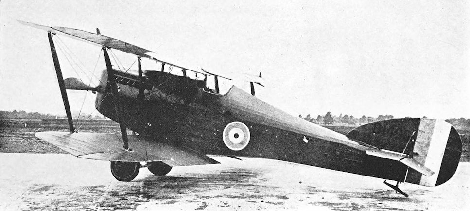
Martinsyde F.3, serial number B.1490.
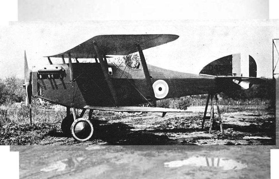
Martinsyde F.4, serial number D.4256.
Nestler Scout
F.C. NESTLER, LTD., entered the aircraft industry before the outbreak of war by obtaining the . British agency for Sanchez-Besa aircraft. During the war the firm were primarily contractors for the manufacture of aircraft components, but towards the end of 1916 they built a small single-seat biplane which had been designed for them by M. Boudot, a Frenchman who later went to the Grahame-White Company. The new aircraft was intended for use as a fighting scout.
The Nestler Scout was a single-bay biplane powered by a 100 h.p. Gnome Monosoupape rotary engine. A shallow, large-diameter spinner was fitted to the airscrew, and the cowling appeared to cover most of the front of the engine. There was no centre-section in the upper wing, and both wing halves met at the trestle-shaped cabane structure. A plain vee undercarriage was fitted. There was no fin, and the rudder was somewhat similar to that of the Avro 504.
In February, 1917, the Nestler Scout was at Hendon, and had been accepted, at least for trial purposes, by the Air Board. The test-flying was done by J. B. Fitzsimmons, a free-lance pilot who had taken up test-flying after being invalided out of the R.F.C. The Nestler was highly manoeuvrable, and Fitzsimmons exploited its tractability daringly but dangerously at very low level. On March 26th, 1917, while he was stunting the Scout in a very high wind, the fabric stripped off the wings. The aircraft dived through the roof of the hangar belonging to the London and Provincial School of Flying and was completely wrecked; Fitzsimmons was killed.
The rebuilding of the Nestler Scout was out of the question, but no further example of the type was built.
SPECIFICATION
Manufacturers: F. C. Nestler, Ltd., 9 Greycoat Street, Westminster, London, S.W.
Power: 100 h.p. Gnome Monosoupape.

Nestler Scout.
Nieuport B.N.1
THE British Nieuport and General Aircraft Co., Ltd., was formed before the outbreak of war for the manufacture of Nieuport designs under licence in the United Kingdom. It was one of the group of firms founded by Samuel Waring (later Lord Waring) of Messrs Waring & Gillow.
One of the chief products of the company was the Sopwith Camel, of which several hundreds were built, but design work was undertaken by the British Nieuport company after Major S. Heckstall-Smith and H. P. Folland, formerly of the Royal Aircraft Factory, joined the staff of the firm in 1917.
The first British Nieuport design was a single-seat fighter powered by the Bentley B.R.2 engine and designated B.N.1. Work on the design began in March, 1918, and when the completed aircraft emerged it showed that Mr Folland had not forgotten some of the constructional features which had placed the S.E.4 so far in advance of all its contemporaries in 1914.
The unstaggered wings of the B.N.1 were of unequal chord and had two-bay bracing, but the interplane struts were of the I-type, as were those of the S.E.4. As originally built, the B.N.1 had a large conical spinner which, with the juxtaposition of the close engine-cowling and rather narrow undercarriage vees, was strongly reminiscent of the S.E.4. The spinner was later removed.
In its construction the B.N.1 incorporated a number of S.E.5 components, the most obvious of which were the tail-skid and lower fin. The fuselage was a simple box girder with rounded top-decking and side fairings behind the engine cowling.
The armament consisted of twin Vickers guns and a single Lewis gun on a special mounting above the centre-section: the latter weapon fired at a slight upward angle, and could be pulled down for reloading and firing upwards. The B.N.1 therefore had the same armament arrangement as the prototype Sopwith Snipe, the Austin A.F.T.3, and the original designs of the Armstrong Whitworth Armadillo and Boulton & Paul Bobolink.
The B.N.1 was a promising design in many ways, and its performance was excellent. It was not developed, however, doubtless because of the official adoption of the Snipe as the B.R.2-powered successor to the Camel. Moreover, the Nieuport company were already engaged on the design of the Nighthawk by the summer of 1918.
SPECIFICATION
Manufacturers: The Nieuport and General Aircraft Co., Ltd., Cricklewood, London, N.W.
Power: 230 h.p. Bentley B.R.2.
Dimensions: Span.: 28 ft. Length: 18 ft 6 in. Height: 9 ft. Chord: upper 6 ft, lower 4 ft 2 in. Gap: 4 ft 3 in. Dihedral: 3. Airscrew diameter: 9 ft 3 in.
Areas: Wings: 260 sq ft. Tailplane: 18 sq ft. Elevators: 10 sq ft. Fin: 5-2 sq ft. Rudder: 5 sq ft.
Weights: Loaded: 2,030 lb.
Performance: Maximum speed at 15,000 ft: 127 m.p.h. Climb to 15,000 ft: 16 min. Ceiling: 26,000 ft. Endurance: 3 hours.
Tankage: Petrol: 36 gallons.
Armament: Two fixed and synchronised Vickers machine-guns mounted on top of the fuselage and firing forward through the airscrew; one Lewis machine-gun on sliding mounting above the centre-section to starboard of centre, firing forwards and upwards over the airscrew.
Serial Numbers: C.3484-C.3486.
Nieuport Nighthawk
THE second British Nieuport type was another single-seat fighter designed by H. P. Folland. This machine was named Nighthawk, and was powered by a 320 h.p. A.B.C. Dragonfly nine-cylinder radial engine.
Like the B.N.1, the Nighthawk was a two-bay biplane, but its bracing was more conventional: four pairs of parallel interplane struts connected the staggered wings. The tail-unit was virtually identical to that of the B.N.1, and retained the S.E.5 under-fin and tail-skid; but the fuselage was faired out to a rounded cross-section throughout its length. With an eye to rapid production, the Nighthawk incorporated several other S.E.5 parts: these included fuselage fittings, stick and rudder bar, and the axle and wheels.
In the air, the Nighthawk was supremely manoeuvrable, and its agility made it an excellent aerobatic mount. Its performance in terms of miles per hour and rate of climb was also extremely good, and there can be no doubt that it would have proved to be a good fighting aeroplane.
The Nighthawk went into production late in 1918, but it is perhaps fortunate that it did not see operational service. It has been said that, if the war had lasted some months longer than it did, the Dragonfly engine would have lost it for Britain at least.
It was, of course, almost inevitable that the Dragonfly should have been chosen for the Nighthawk; and in fact the Nighthawk was the first Dragonfly-powered aircraft to be ordered in quantity.
Mr Granville Bradshaw initiated design work on the Dragonfly after A.B.C. Motors, Ltd., had received an official invitation, in April, 1917, to submit designs for the 1918 engine programme. The company was given an order for three experimental engines, to be called Dragonfly, in August, 1917. The initial success of the smaller A.B.C. Wasp in its early trials encouraged Bradshaw to press his new design upon the Government. He claimed that the Dragonfly would deliver 340 h.p. for a weight of a little over 600 lb, and suggested that it would be preferable to build the Dragonfly rather than the Wasp. Like the Wasp, the Dragonfly was designed for ease of production; and it offered such great power that it was a very attractive proposition.
In October, 1917, the Air Board had decided to order the Bentley B.R.2 rotary engine in quantity, and by the middle of that month orders had been placed of sufficient size to ensure an ultimate production of 900 B.R.2 engines per month. Two days after the Air Board had made its decision, however, the Dragonfly was brought to the notice of the Board’s members.
Mindful of its unfortunate experiences arising out of the ordering of the untried Sunbeam Arab, the Board approached the Dragonfly with caution. The members felt that they could not afford to pass over an engine which seemed so full of promise; but they did not want to cancel or reduce the production of B.R.2s in favour of an untried design. The B.R.2 programme was therefore not disturbed, and Vickers, Ltd., were asked to produce the Dragonfly at their Crayford works as a first step.
As 1918 advanced, both the Air Board and the aircraft industry became more and more convinced that the Dragonfly was the best engine available, and large contracts were placed during the year. Altogether, 11,050 were ordered from thirteen contractors* and the ultimate intention was for the Dragonfly to supersede most other engines in production. The production programme was planned to ensure delivery of 4,135 Dragonflies by the end of June, 1919.
* The contractors and the numbers of Dragonfly engines ordered from each were these: Beardmore Aero Engine, Ltd.: 1,500; Crossley Motors, Ltd.: 1,000; Ransome, Sims & Jeffries: 500; F. W. Berwick & Co., Ltd.: 1,000; Belsize Motors, Ltd.: 1,000; Maudslay Engineering Co., Ltd.: 500; Vulcan Motor & Engineering Co., Ltd.: 600; Vickers, Ltd.: 1,000; Sheffield Simplex: 500; Guy Motors, Ltd.: 600; Clyno Engineering Co.: 500; Ruston, Proctor & Co., Ltd.: 1,500; Humber, Ltd.: 850.
After the engine was in production, however, it was found to be far from satisfactory. It was heavier than the original estimate; gave less power; and, worst of all, vibrated exceedingly badly in flight tests. Mechanical failure usually occurred after only a few hours’ flying. New pistons were fitted, and late in 1918 cylinder heads of the type developed at the Royal Aircraft Establishment by Professor A. H. Gibson and S. D. Heron were installed.
But the engine suffered from dynamic unbalance and synchronous torsional vibration in an extreme degree. The latter phenomenon was not understood in 1918, but it began to be realised that a complete re-design of the engine would have to be undertaken in order to cure the trouble. Before production contracts were cancelled, a total of 1,147 Dragonfly engines were produced; only twenty-three had been delivered by the end of 1918, but production continued into 1919.
Fortunately, the Armistice prevented the introduction of the Dragonfly into the service. In view of the extent to which the Air Board had committed itself to the engine, a continuation of the war would have brought catastrophe when the Dragonfly was introduced in large numbers. It was brought to the stage where it would run reliably for two and a half hours, and one school of thought held the view that it would be worthwhile to replace each aeroplane’s engine after each patrol in view of the power it delivered.
The failure of the A.B.C. Dragonfly led to the collapse of the Nighthawk production programme, for the aircraft had been ordered in large quantities before the engine’s shortcomings had been recognised as chronic. The Nighthawk went into limited service at home and in India, where No. 1 Squadron had a few in addition to its standard equipment of Snipes. The Nighthawk was occasionally fitted with the Bristol Jupiter engine in place of the erratic Dragonfly. Among experiments in which Nighthawks were used were those which were conducted with special crash-proof fuel tanks.
The type was withdrawn as obsolete in the spring of 1923, whereafter enough airframes were kept in store to provide sufficient conversions to Nightjars to maintain twelve machines for two years. The Nightjar was a modification of the basic Nighthawk for use from aircraft carriers, and was one of a series of Nighthawk developments made by the Gloucestershire Aircraft Co., Ltd., which took over the Nieuport design in 1920. Several Nighthawk airframes were converted into the various Gloucester Mars types. Fifty of the versions which were alternatively known as Sparrowhawks were supplied to Japan in 1922.
SPECIFICATION
Manufacturers: The Nieuport and General Aircraft Co., Ltd., Cricklewood, London, N.W. Other Contractors: The Gloucestershire Aircraft Co., Ltd., Cheltenham.
Power: 320 h.p. A.B.C. Dragonfly I.
Dimensions: Span: 28 ft. Length: 18 ft 6 in. Height: 9 ft 6 in. Chord: 5 ft 3 in. Gap: 4 ft 6 in. Span of tail: 9 ft. Airscrew diameter: 9 ft.
Areas: Wings: 276 sq ft. Ailerons: each 9-3 sq ft, total 37-2 sq ft. Tailplane: 18 sq ft. Elevators: 10 sq ft. Fin: 5-2 sq ft. Rudder: 5-3 sq ft.
Weights and Performance: No. of Trial Report: M.259. Date of Trial Report: July, 1919. Type of airscrew used on trial: A.B.8979. Weight empty: 1,500 lb. Military load: 218 lb. Pilot: 180 lb. Fuel and oil: 320 lb. Weight loaded: 2,218 lb. Maximum speed at ground level: 151 m.p.h.; at 6,500 ft: 140 m.p.h.; at 10,000 ft: 138-5 m.p.h.; at 15,000 ft: 134 m.p.h. Climb to 5,000 ft: 3 min; to 6,500 ft: 4 min 10 sec; to 10,000 ft: 7 min 10 sec; to 15,000 ft: 12 min 40 sec; to 20,000 ft: 20 min. Service ceiling: 24,500 ft. Endurance: 3 hours.
Tankage: Petrol: 40 gallons. Oil: 4 gallons.
Armament: Two fixed forward-firing Vickers machine-guns mounted on top of the fuselage and synchronised to fire through the revolving airscrew.
Service Use: R.A.F. Squadrons, Nos. 1 and 8 (post-war).
Serial Numbers: Between and about H.8533 and H.8544; between and about J.2405 and J.2416; between and about J.6925 and J.6930.
Notes on Individual Machines: H.8544, J.2405, J.2416 and J.6926 became Mars VI; H.8539 and J.6930 became Nightjars (Mars X); J.6925 was a Nighthawk used by No. 1 Squadron.
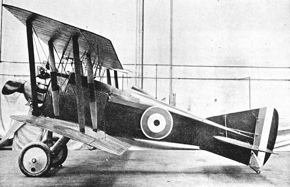
Nieuport Nighthawk prototype.
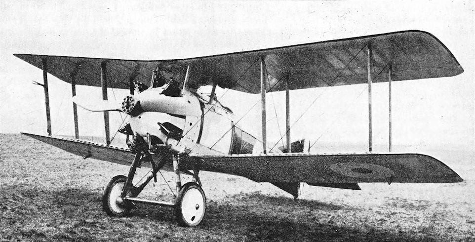
The standard Dragonfly-powered Nieuport Nighthawk of the type built by H.H.Martyn and Co., with heating muffs on exhaust pipes.
Nieuport London
ALTHOUGH the Nieuport London was not officially regarded as being in the same category as the Manchester, Bourges, Oxford and Cobham, it had several features in common with them. It was designed for two A.B.C. Dragonfly engines; the installation of two high-compression Siddeley Pumas was envisaged as a means of testing the airframe; but no example of the London was completed before the Armistice, and the aircraft did not fly until 1920.
Whereas the other four Dragonfly-powered twins were designed as high-speed day bombers, however, the London was intended to be a night bomber; and particular attention had been paid to structural simplicity in order to achieve rapid production. The aircraft was designed in 1918 by H. P. Folland, and was an outstanding example of his genius, both structurally and aerodynamically.
The London was a triplane of rather angular appearance. It was built of wood throughout, and the number of metal fittings was kept to a minimum: the structural members were of deal, pine and cypress; wooden pegs and dowels were used; joints were made in the simplest possible fashion, with nails and brass wire sewing; and the fuselage was covered with quarter-inch tongue-and-groove match-boarding. The wings and tail unit were fabric covered.
All control surfaces were horn-balanced. Ailerons were fitted to all three mainplanes, but the London proved to be so responsive to the controls that the top and middle ailerons were removed and the wings suitably modified; the remaining bottom ailerons were quite adequate to provide lateral control. The tail-unit incorporated a keel-fin reminiscent of the S.E.5.
The undercarriage consisted of two separate single-wheel units, one under each engine: the wheel track was therefore wide. The Dragonfly engines were mounted in carefully-faired nacelles which contrasted markedly with the London’s severe lines. With the A.B.C. radials the aircraft was officially named London Mark I; the designation London Mk. II was allotted to a Puma-powered version which had been designed to enable the airframe to be test-flown if Dragonflies were not available in time.
It seems doubtful whether the London Mk. II was ever built. By the time an airframe was completed, Dragonflies were available, and H.1740 appeared with those engines.
But by then the war was over, and new military aircraft were not wanted. It was proposed to convert the London into a transport aircraft with accommodation for thirteen passengers or 2,685 lb of mails or freight, but development of the design ceased when the Nieuport and General Aircraft Company closed down in August, 1920.
SPECIFICATION
Manufacturers: The Nieuport and General Aircraft Co., Ltd., Cricklewood, London, N.W.
Power: London Mk. I: two 320 h.p. A.B.C. Dragonfly I. London Mk. II: two 290 h.p. Siddeley Puma.
Dimensions: Span: 59 ft 6 in. Length: 37 ft 6 in. Height: 17 ft 6 in. Chord: 6 ft 8 in. Gap: 5 ft 10 in. Stagger: nil. Span of tail: 20 ft 6 in.
Areas: Wings: 1,100 sq ft. Ailerons: each 20 sq ft, total 120 sq ft. Tailplane: 64 sq ft. Elevators: 40 sq ft. Fin: 30 sq ft. Rudder: 20 sq ft.
Performance: Maximum speed at ground level: 100 m.p.h. Climb to 10,000 ft: 30 min. Endurance: 4 hours. Tankage: Petrol: 175 gallons.
Armament: A double-yoked pair of Lewis machine-guns could be carried on a Scarff ring-mounting on the front cockpit. The bomb load consisted of nine 250-lb bombs or their equivalent weight.
Serial Number: H.1740.

The Nieuport London triplane night bomber was designed for easy production, hence its very angular lines. Designed in 1918 Britain, it was not flown until 1920 when its engines were finally ready.
Norman Thompson N.T.4 and N.T.4a
IN March 1915, the Admiralty ordered fifty flying-boats of the type which became well known as the Curtiss H.4, or more popularly as the “America”. When fitted with satisfactory engines these Curtisses gave quite a good account of themselves and proved that flying-boats could be of use in warfare.
On October 4th, 1915, the name of the White and Thompson company was changed to the Norman Thompson Flight Co., Ltd. The first aircraft to appear under the new name was a handsome twin-engined flying-boat of the same general type as the Curtiss H.4. Either because it was the fourth flying-boat design of the Bognor company or because it was desired to retain the numeral of the Curtiss type’s designation as indicative of a class of flying-boat, the new machine was designated N.T.4.
Like the Curtiss H.4, the Norman Thompson N.T.4 was known in the R.N.A.S. as an “America” or, after the introduction of the Curtiss H.12, as a “Small America”. There was, however, no real connexion between the two flying-boats, and the N.T.4 differed from the Curtiss type in several major respects. It was larger, had four-bay wings and a different hull, and was driven by pusher engines instead of the tractors of the Curtiss H.4.
The hull was a boat-built structure rather similar to the Curtiss hull but with finer lines. It had only one step, and the size and form of the hull fins recalled Curtiss practice, but a shallow and stubby forebody was used. Enclosed accommodation was provided for the crew, but the early form of cabin did not have as much glazing as would have seemed necessary; even the vertical windows had very wide framing to reduce the view further.
The wings were of unequal span, but the extensions of the upper mainplanes were comparatively short; they were braced by cables, the landing wires running from king-posts above the outermost interplane struts. The ailerons of the first few N.T.4s projected behind the trailing edge of the upper wing, to which they were fitted.
These first machines were powered by two 150 h.p. Hispano-Suiza engines installed as pushers and driving two-bladed airscrews. The engines were completely uncowled, and each had a large rectangular radiator mounted on the forward interplane struts. A small gravity fuel tank was mounted between the central struts, high up near the upper wing.
The first N.T.4 of the first batch, No. 8338, was experimentally fitted with a two-pounder Davis gun. The gun was carried on a substantial horizontal mounting which was built above the cabin top. Supporting struts ran downwards through a cabin window on either side. The Davis gun was officially abandoned as a weapon, however, and never became standard armament for the N.T.4.
N.T.4s of the second and all subsequent batches differed from the early machines in having more powerful engines. These were two of the 200 h.p. geared Hispano-Suizas, and with them the flying-boat was designated N.T.4a. The design of the cabin was successively modified to provide more transparency, and the final production version had all-over glazing of the cabin top. The gravity fuel tank was raised by placing it on top of the upper wing. For starting, fuel was pumped up to the gravity tank by hand, and once the N.T.4a was airborne the supply was maintained by two wind-driven pumps on top of the hull.
In the later N.T.4a’s the ailerons were reduced in chord to bring their trailing edges flush with that of the upper mainplane; and the lower portion of the rudder was covered with plywood, for it was frequently awash. All the N.T.4s and N.T.4a’s were characterised by the same tail-unit, which incorporated a large low aspect-ratio fin and plain broad-chord rudder; the tailplane was mounted half-way up the fin, and was braced to the hull by struts.
The Norman Thompson N.T.4a was quite widely used by the R.N.A.S. in home waters, presumably as a patrol machine and latterly as a trainer. It had quite a good performance, and probably would have made something of a name for itself if its appearance had not coincided so closely with the advent of the “Large America” types. Production continued into the summer of 1918, when it was hoped that the N.T.4a would be replaced by the Norman Thompson N.2C, a later design which incorporated N.T.4a flight organs.
SPECIFICATION
Manufacturers: The Norman Thompson Flight Co., Ltd., Bognor Regis, Sussex.
Power: Two 150 h.p. Hispano-Suiza; two 200 h.p. Hispano-Suiza.
Dimensions: Span: upper 78 ft 7 in., lower 60 ft 10 in. Length: 41 ft 6 in. Height: 14 ft 10 in. Chord: 7 ft 6 in. Gap: 7 ft 6 in. Stagger: 8 1/2 in. Dihedral: 1° 30'. Incidence: 5°. Span of tail: 16 ft.
Areas: Wings: upper 518 sq ft, lower 418 sq ft, total 936 sq ft. Ailerons: each 30-9 sq ft, total 61-8 sq ft. Tailplane: 75 sq ft. Elevators: 61-5 sq ft. Fin: 24 sq ft. Rudder: 31-9 sq ft.
Weights and Performance (for 200 h.p. engines): Date of Trial Report: September 24th, 1917. Type of airscrews used on trial: D.1062. Weight empty: 4,572 lb. Military load: 273 lb. Crew: 540 lb. Fuel and oil: 1,084 lb. Loaded: 6,469 lb. Maximum speed at 2,000 ft: 95 m.p.h.; at 6,500 ft: 93 m.p.h.; at 10,000 ft: 91 m.p.h. Climb to 2,000 ft: 3 min 50 sec; to 6,500 ft: 15 min; to 10,000 ft: 31 min 5 sec. Service ceiling: 11,700 ft.
Armament: Uncertain. Probably a Lewis machine-gun would be fitted on a bracket above the cabin, and bombs might be carried under the lower wings. An experimental installation of a two-pounder Davis recoilless gun was made in one N.T.4.
Service Use: Used at R.N.A.S. Stations, Calshot, Cattewater, Dundee, Felixstowe, Killingholme, Invergordon, Scapa Flow.
Production: Serial numbers were allotted for at least fifty N.T.4s and N.T.4a’s.
Serial Numbers: 8338-8343. 9061-9064. N.2140-N.2159. N.2740-N.2759. 9061 was flown at Calshot.
Costs:
Airframe without engines, instruments or armament £3,610
200 h.p. Hispano-Suiza engine (each) £1,004
Norman Thompson N.2C
THE Norman Thompson N.2C was a 1918 development of the N.T.4a. It consisted of the wings and tail-unit of the N.T.4a fitted to a hull which was built on the Porte principle instead of being boat-built, and the type was intended to be a replacement for the N.T.4a. The Norman Thompson company had been contractors for hulls for F.2A flying-boats since the spring of 1917, and were therefore familiar with the system of construction.
It was perhaps fortunate that the hull of the N.2C was such a simple structure, because F. P. H. Beadle had left the Norman Thompson company at the end of 1917. His experience had been a considerable asset to the company in the production of their earlier flying boats.
Construction of two prototypes began in January 1918. The hull was basically a cross-braced girder structure, plywood-covered and generally similar to the hulls of the F-boats. The wings appeared to be standard N.T.4a surfaces. The rudder differed in shape from that of the N.T.4a, probably because the N.2C hull had a much shorter stern-post. Power was provided by two Sunbeam Arab engines driving four-bladed pusher airscrews.
The Norman Thompson N.2C was intended for patrol duties and was equipped with wireless, guns and bombs. The prototypes were completed, but the type arrived too late to go into production or to see service.
SPECIFICATION
Manufacturers: The Norman Thompson Flight Co., Ltd., Bognor Regis, Sussex.
Power: Two 200 h.p. Sunbeam Arab.
Dimensions: Span: upper 78 ft 7 in., lower 60 ft 10 in. Chord: 7 ft 6 in. Gap: 7 ft 6 in.
Areas: Wings: 936 sq ft.
Serial Numbers: N.82-N.83.

Norman Thompson N.T.4a. Late production N.T.4a with final form of cabin, two 200 h.p. Hispano-Suiza engines, constant-chord ailerons, and gravity tank above the upper wing.
N2147 outside the hangar at Middleton judging by the light rail. The hull is now a dark colour with a light bottom.
N2147 outside the hangar at Middleton judging by the light rail. The hull is now a dark colour with a light bottom.

Norman Thompson N.T.4 with 150 h.p. Hispano-Suiza engines, broad-chord ailerons, and late cabin enclosure.
Norman Thompson N.1B
EARLY in 1917 work began on the construction of a small two-seat flying-boat which was intended to be a high-performance fighting machine. In the Norman Thompson works it was known as the T.N.T., or Tandem Norman Thompson, in view of its seating arrangement; as an aircraft it fell into the Admiralty category N.1B.
The T.N.T. was a remarkably compact little machine in which considerable attention was paid to detail in order to reduce drag. The hull was a boat-built structure with two open cockpits in the deep forebody. The two-bay wings were unusual (on a flying-boat of that period) in two respects: they were of equal span, and ailerons were fitted to upper and lower wings. The ailerons were originally connected by light struts, but these were replaced by cables. Interplane bracing was by cables; the duplicated flying wires were carefully faired together. The wings were arranged to fold forwards, as on the A.D. Flying Boat.
The fin and rudder assembly were quite different in appearance from any other Norman Thompson design, for they were of comparatively high aspect-ratio. The base of the rudder was plywood-covered.
Power was provided by a 200 h.p. Hispano-Suiza engine which drove a four-bladed pusher airscrew. The trailing portion of the upper wing was cut away to allow the airscrew to revolve.
The Norman Thompson N.1B was launched in September, 1917, and performed well. The machine underwent makers’ trials until the end of the year, when it was turned over to the R.N.A.S. at the Isle of Grain for Service trials. The Norman Thompson company were optimistic about the outcome, because they claimed to have achieved a speed of 108 m.p.h. and a climb of 20,000 feet in 18 1/5 minutes with the N.1B: these were quite prodigious performances for a flying-boat at that time.
It seems doubtful that these results could have been obtained with a worthwhile load, for the official test figures fell a long way short of them. In particular, it was obvious that the machine could never have reached 20,000 feet on its official trial.
The N.1B was not officially adopted, presumably because its performance did not represent much of an advance over existing types.
SPECIFICATION
Manufacturers: The Norman Thompson Flight Co., Ltd., Bognor Regis, Sussex.
Power: 200 h.p. Hispano-Suiza.
Dimensions: Span: 34 ft 3 in. (folded, 13 ft 2 in.). Length: 26 ft 5 in. (folded, 32 ft 8 in.). Height: 9 ft 7 in.
Areas: Wings: 357 sq ft.
Weights and Performance: No. of Trial Report: N.M. 173. Date of Trial Report: May 18th, 1918. Weight empty: 1,895 lb. Military load: 20 lb. Crew: 360 lb. Fuel and oil: 398 lb. Loaded: 2,673 lb. Maximum speed at 2,000 ft: 93 m.p.h.; at 6,500 ft: 92 m.p.h.; at 10,000 ft: 86-5 m.p.h. Climb to 2,000 ft: 3 min 30 sec; to 6,500 ft: 14 min 20 sec; to 10,000 ft: 27 min 35 sec. Service ceiling: 12,600 ft. Endurance: 3 1/2 hours at 6,000 ft.
Armament: Uncertain. Presumably one Lewis machine-gun fired by the observer.
Serial Number: N.37.

Norman Thompson N.1B (N37).

Norman Thompson N.1B in its original form with light struts connecting upper and lower ailerons, but without control horns and spanwise balance cables on upper ailerons.
Norman Thompson N.T.2B
THE Norman Thompson Flight Company were contractors for the construction of the little F.B.A. trainer flying-boat, a frail-looking machine of French origin which nevertheless performed much useful work in training flying-boat pilots.
For the same purpose the Bognor company produced a workmanlike and more substantial two-seat flying-boat which was obviously a descendant of the White and Thompson No. 3 Flying-boat. The new Norman Thompson machine was known as the N.T.2B, a designation which conflicted oddly with that of its immediate predecessor, the N.T.4. It seems probable, however, that the two-seater came within the Admiralty category N.2B, whence the numeral might have been derived.
The hull was somewhat similar in general appearance to that of the White and Thompson No. 3, but had improved lines. It was a boat-built structure with a single step: over a framework of formers and stringers were applied two thicknesses of planking with a layer of oiled calico between them; the outer planking ran fore and aft. A neat enclosed cabin was provided for the instructor and his pupil, who sat side-by-side. Dual control was, of course, fitted.
The two-bay wings were of unequal span: the extensions of the upper wings were braced from kingposts which were enclosed in fin surfaces of characteristic shape, situated above the outer pairs of interplane struts. Only the upper wings had ailerons, which projected behind the trailing edge of the mainplane.
Abaft the wings the hull was little more than a boom to support the tail-unit. The vertical surfaces were very similar to those of the N.T.4, and the tailplane was set high on the fin. The bottom of the rudder was covered with plywood, and a beaching skid was fitted under the stern-post.
Power was provided by a 160 h.p. Beardmore engine mounted between the wings and driving a four-bladed pusher airscrew. The engine was completely uncowled, and a tall rectangular radiator was mounted in front of the installation. The starting crank handle protruded through the radiator.
The N.T.2B was accepted by the Admiralty and was ordered into production. It seems probable that most of the first fifty production machines had the Beardmore engine, though some are known to have had the 150 h.p. Hispano-Suiza. Late in 1917 it was decided to fit a more powerful unit.
First choice fell on the 200 h.p. Sunbeam Arab, and it seems that the first installation was made in N.2294, an N.T.2B which had originally had a Beardmore. The more powerful engine brought with it some problems of longitudinal control. Its torque was greater than that of the Beardmore, and had to be overcome by mounting the engine slightly to starboard of centre.
The N.T.2B proved to be a useful little flying-boat, so much so that R.N.A.S. demands for it exceeded the production capacity of the Norman Thompson works. Contracts were therefore given to S. E. Saunders and the Supermarine Aviation Works, and both firms built the N.T.2B under licence.
In view of the Sunbeam Arab’s ill-starred career, it comes as no surprise to learn that the ultimate production version was powered by the 200 h.p. Hispano-Suiza engine. Again the problem of torque reaction arose, and ultimately a form of slewed engine mounting was evolved. This mounting was tested on N.2569 and proved to be satisfactory. The installation of the Hispano-Suiza was similar to that of the Sunbeam Arab, but could be distinguished by the starting crank handle running through the radiator: the Arab had no such frontal handle.
The N.T.2B remained the standard flying-boat trainer until the Armistice. No further development of the design took place because of the absorption of the Norman Thompson company by Handley Page Ltd. The latter firm sent two N.T.2Bs (N.2284 and N.2293) to Peru to pioneer air transportation in 1919, but beyond that the type did not survive for long.
SPECIFICATION
Manufacturers: The Norman Thompson Flight Co., Ltd., Bognor Regis, Sussex.
Other Contractors: S. E. Saunders, Ltd., East Cowes, Isle of Wight; The Supermarine Aviation Works, Ltd., Woolston, Southampton.
Power: 160 h.p. Beardmore; 200 h.p. Sunbeam Arab; 150 h.p. Hispano-Suiza; 200 h.p. Hispano-Suiza.
Dimensions: Span: upper 48 ft 4 3/4 in., lower 27 ft 6 3/4 in. Length: 27 ft 4 1/2 in. Height: 10 ft 8 in. Chord: 5 ft 6 in. Gap: 5 ft 6 in. Stagger: nil. Dihedral: 1°. Incidence: 5°.
Areas: Wings: 453 sq ft.
Weights and Performance (with Sunbeam Arab engine): No. of Trial Report: N.M.211. Date of Trial Report: August 15th, 1918. Type of airscrew used on trial: D.1465. Weight empty: 2,321 lb. Military load: nil. Crew: 360 lb. Fuel and oil: 488 lb. Loaded: 3,169 lb. Maximum speed at 2,000 ft: 85 m.p.h.; at 6,500 ft: 83-5 m.p.h.; at 10,000 ft: 80-5 m.p.h. Climb to 2,000 ft: 4 min 10 sec; to 6,500 ft: 16 min 50 sec; to 10,000 ft: 33 min 40 sec. Service ceiling: 11,400 ft.
Tankage: Petrol: 60 gallons. Oil: 8 gallons.
Service Use: Used for training purposes at R.N.A.S. Stations Calshot, Lee-on-Solent, Felixstowe.
Production and Allocation: Precise figures are not available, but it seems probable that over 150 Norman Thompson N.T.2Bs were built. On October 31st, 1918, the R.A.F. had seventy-nine on charge. Only twenty-three were at coastal stations; two were with contractors; three were at experimental units; the remaining fifty-one were in store.
Serial Numbers: N.1180-N.1189: built by Norman Thompson. N.2260-N.2359: built by Norman Thompson. N.2400 and onwards, probably to N.2419 at least. N.2500-N.2523: built by Saunders. N.2555-N.2579: built by Norman Thompson. N.2760-N.2789: built by Supermarine. Notes on Individual Machines: N. 1189: R.N.A.S., Lee-on-Solent. N.2268: R.N.A.S., Lee-on-Solent. N.2284 and N.2293 went to Peru in 1919. N.2290: became G-EAQO. N.2555: R.N.A.S., Calshot (this N.T.2B had a 150 h.p. Hispano-Suiza engine). N.2561: R.N.A.S., Calshot. N.2569: first slewed engine installation.
Costs:
Airframe without engine and instruments £1,477 0s.
Engines:
160 h.p. Beardmore £1,045 0s.
Sunbeam Arab £1,017 10s.
200 h.p. Hispano-Suiza £1,004 0s.

Norman Thompson N.T.2B. Early production N.T.2B, serial number N.1181, with 160 h.p. Beardmore engine.

Norman Thompson N.T.2B. N.2294 with Sunbeam Arab engine. This N.T.2B previously had the Beardmore engine.

Norman Thompson N.T.2B. N.2569 with a 200 h.p. Hispano-Suiza engine.
Parnall Scout
DURING the 1914-18 war, the wood-working firm of Parnall & Sons of Bristol built a considerable number of aeroplanes, particularly Avro 504s and Fairey Hamble Babies, for the Admiralty. The firm’s products were characterised by excellent workmanship and so favourably impressed the Admiralty that Parnalls were requested to undertake original design work.
The first Parnall aeroplane was a large single-seat biplane of unusual appearance, variously known as the Parnall “Zeppelin Chaser” or “Night Flyer”, and powered by a 250 h.p. Sunbeam engine. It was designed by A. Camden Pratt and was built in 1916. The Parnall Scout was in fact designed specifically as an anti-Zeppelin aeroplane and, as befitted its nocturnal duties, it was painted all black.
It was a two-bay biplane with wings of unequal span and chord, and the mainplanes were very heavily staggered. The upper wing was set low above the fuselage, presumably to give the pilot the best possible view upwards and forwards: his cockpit was situated immediately behind the trailing edge of the centresection. The fuselage was carried well above the lower wing, and the radiator was underslung.
The Parnall Scout proved to be greatly overweight when completed, and it is doubtful whether it ever flew. It was sent to Upavon for its official tests, but calculations made there showed that the factor of safety was dangerously low and the aircraft was condemned.
SPECIFICATION
Manufacturers: Parnall & Sons, Mivart Street, Eastville, Bristol.
Power: 250 h.p. Sunbeam.
Dimensions: Span: upper 44 ft, lower 40 ft. Chord: upper 7 ft, lower 5 ft 6 in. Gap: 5 ft 6 in. Stagger: 4 ft. Dihedral: 4. Incidence: 2. Span of tail: 18 ft.
Areas: Wings: 516 sq ft. Ailerons: total 36 sq ft. Tailplane: 74 sq ft. Elevators: 38 sq ft. Fin: 6-5 sq ft. Rudder: 12-75 sq ft.
Performance: Maximum speed at ground level: 113-5 m.p.h.; at 10,000 ft: 101-5 m.p.h.
Tankage: Petrol: main tank 36 gallons.
Serial Number: N.505, built under Contract No. C.P. 124455/16/24486.

Parnall Scout.
Parnall N.2A, the Panther
IN 1917, Parnall & Sons secured the services of Harold Bolas, who was released from the Air Department of the Admiralty for employment as the firm’s chief designer.
Mr. Bolas had had considerable experience of aeronautical design work. He had started his aeronautical career in the drawing office of the Army Aircraft Factory at Farnborough, and had worked on the designs of some of the early Army airships. While with the Air Department he had had a share in the design of the A.D. Navyplane, which was built by the Supermarine Aviation Works in 1916. The Navyplane had a wooden monocoque nacelle which weighed only 85 lb, and in its design careful attention had been paid to the provision of good outlook for the crew.
The first Bolas-designed Parnall aircraft was a two-seat biplane intended for Fleet reconnaissance and spotting duties, and came within the Admiralty category N.2A. The first prototype, N.91, appeared in 1917, and was followed by five others consecutively numbered up to N.96. By the time the sixth machine appeared, the type had been officially named Panther. The fourth prototype, N.94, was used for structural tests.
The Panther was a small single-bay biplane of unusual appearance and design, powered by a 230 h.p. Bentley B.R.2 rotary motor. The fuselage was a wooden monocoque on a basic frame of four longerons which carried the plywood formers; the outer skin consisted of 1-6 mm birch plywood which was glued and screwed to the formers. The pilot and observer were accommodated in a high, elongated blister on top of the basic fuselage form; and the pilot had an excellent view, particularly for deck-landing, from his elevated position.
Since the Panther was designed for use from ships and the early carrier vessels, it had to be made to fold in some way in order to conserve stowage space. An unusual expedient was adopted to achieve this end: the fuselage folded sideways to starboard at a point just behind the observer’s cockpit. A special channel was provided on the starboard side of the fuselage, and through it passed the control cables to the tail surfaces.
The undercarriage was basically a plain vee structure, and was so on N.91 and N.92. A hydrovane was added in front of the wheels to prevent overturning in the event of ditching, and Grain flotation gear air bags were fitted to the top of each undercarriage vee. Other air bags were fitted inside the rear portion of the fuselage.
The mainplanes had spindled spruce spars, and the ribs were of plywood capped with spruce. The ailerons were inset from the wing-tips which, if need be, could be detached for stowage. There was a large hole in the centre-section: this not only enabled the pilot to see vertically upwards but also provided him with the means of ingress into his cockpit.
Entering the pilot’s cockpit of the Panther was something of a gymnastic feat. The trailing edge of the centre-section was hinged at the rear spar, and had to be lowered as the pilot’s first action in approaching his cockpit. He then climbed into the hole in the centre-section and lowered himself into his seat below.
The tail-unit displayed further originality of thought, for the hinge-lines of both rudder and elevators were raked forward relative to the line of flight. Plain elevators were originally fitted to N.91 and N.92, but these had to be replaced by balanced surfaces of greater area in order to improve the handling characteristics at speeds near the stall.
A production contract for 300 Panthers was given to the Parnall concern a few days before the Armistice. When the war ended the Air Ministry asked for the contract to be reduced to 150 machines. The Parnall company was owned by W. & T. Avery, Ltd., of Smethwick, who would not agree to this reduction, and the Air Ministry offered the revised contract to the British and Colonial Aeroplane Co.
The offer was accepted with alacrity, and production was under way at Filton in 1919. During that year, fifty-one Panthers were delivered, and ninety-nine were completed in 1920. The original Parnall Company ceased to construct aeroplanes.
The Panther was used by the Fleet Air Arm until 1924, when it was replaced by the Fairey HID. Two Panthers were supplied to America in 1920 and twelve to Japan in 1921-22. The Japanese machines were flown from the naval base at Yokosuka.
Oleo undercarriages were later fitted to a number of Panthers, as were larger horn-balanced rudders. The latter modification was most probably made to improve rudder control at low speeds, lack of which was the machine’s only real fault; otherwise it was said to be delightful to fly and almost devoid of vices.
SPECIFICATION
Manufacturers: Parnall & Sons, Mivart Street, Eastville, Bristol.
Other Contractors: The British and Colonial Aeroplane Co., Ltd., Filton, Bristol.
Power: 230 h.p. Bentley B.R.2.
Dimensions: Span: 29 ft 6 in. Length: 24 ft 11 in. (folded, 14 ft 6 in.). Height: 10 ft 6 in. Chord: 6 ft 3 in. Gap: maximum 6 ft 3 in., minimum 6 ft 2 1/2 in. Span of tail: 12 ft. Airscrew diameter: 9 ft 1 1/4 in.
Areas: Wings: 336 sq ft. Ailerons: each 11-3 sq ft, total 45-2 sq ft. Tailplane: 18-4 sq ft. Elevators: 19-3 sq ft. Fin: 6-85 sq ft. Rudder: 4-4 sq ft.
Weights and Performance: No. of Trial Report: M.196. Date of Trial Report: May, 1918. Type of airscrew used on trial: Lang 4040. Weight empty: 1,328 lb. Military load: 366 lb. Crew: 360 lb. Fuel and oil: 541 lb. Weight loaded: 2,595 lb. Maximum speed at 6,500 ft: 108-5 m.p.h.; at 10,000 ft: 103 m.p.h. Climb to 2,000 ft: 2 min 20 sec; to 6,500 ft: 9 min 20 sec; to 10,000 ft: 17 min 5 sec. Service ceiling: 14,500 ft. Endurance: 45 hours at 10,000 ft.
Tankage: Petrol: 58 gallons (48 gallons in the main tank under the pilot’s seat and 10 gallons in the upper centresection in two tanks, one either side of the cut-out). Oil: 10 gallons.
Armament: One movable Lewis machine-gun on a pillar-mounting in the rear cockpit. On N.91 a fixed forward-firing Vickers machine-gun was mounted beside the pilot’s cockpit on the port side.
Service Use: After the war, the Panther was used on the aircraft carriers H.M.S. Argus and H.M.S. Hermes. It was also flown from land stations at Leuchars (No. 406 Fleet Fighter Flight), Gosport (No. 421 Flight), and Port Grange.
Production: Six prototypes and 150 production Panthers were built.
Serial Numbers: N.91-N.96. N.7400-N.7549: built by British and Colonial Aeroplane Co., Ltd., under Contract No. 38A/988/C.1035.

Parnall Panther. The sixth prototype with hydrovanes fitted and air bags inflated.

This photograph of a Parnall Panther aboard HMS Argus illustrates well the longitudinal arrester wires, the hinged wooden flaps mounted transversely, the hooks on the axle and the forward hydrovane. The period was 1919-20.
Pemberton-Billing P.B.9
THE name of Noel Pemberton-Billing has already appeared in this book as the planner of the raid on the Zeppelin sheds at Friedrichshafen, made on November 21st, 1914, by three Avro 504s of the R.N.A.S.
Eleven years earlier, Pemberton-Billing had begun practical experiments in aeronautics. In 1903 he designed a man-lifting kite which was completed in the following year, and in 1905-6 he designed and made a valveless rotary petrol engine with a view to applying power to his kites. Until 1909 he experimented with several peculiar monoplanes which were only partially successful, and thereafter abandoned his aeronautical activities until September, 1913. He then began the design and construction of marine aircraft in the small factory he had taken over at Woolston.
His designs all displayed startling originality of thought and application, and as evidence of his faith in the future of marine aircraft he coined the name “Supermarine” as his telegraphic address. The first aircraft to bear that name was the Supermarine P.B.1, a biplane flying boat which was displayed at the Olympia show in March, 1914. In June, 1914, the business became a limited company, known as Pemberton-Billing Ltd. Two months later Britain was at war.
Such was Pemberton-Billing’s belief in the air and such the vitality of his thought that he immediately conceived the idea of a speedy single-seater for scouting purposes, which could be built quickly and easily in order to help provide the large number of aeroplanes that he believed would turn the war in the Allies’ favour at an early date.
The new type was designated P.B.9, although it seems to have been Pemberton-Billing’s thirteenth design for a power-driven aircraft. From the commencement of design work until completion only eight days elapsed; of that period the construction occupied seven days. The P.B.9 was (for obvious reasons) nicknamed the “Seven-Day Bus”.
It was a thoroughly conventional single-bay biplane, simple in construction and appearance. Typical of its simplicity was the shape of the engine cowling: this curved in one plane only, in conformity to the shape of the upper longerons as they curved downwards to the forward bearing for the 50 h.p. Gnome engine. The fuselage was wide enough to accommodate an 80 h.p. Gnome but none was available. The output of the rather old 50 h.p. Gnome was very nominal, yet the P.B.9 performed remarkably well with it.
The interplane bracing was unusual, for there were no conventional centre-section struts. Their place was taken by full-length interplane struts placed close up against the fuselage sides. Each mainplane was made in one piece, and the spars of the lower wing ran under the fuselage. The attachment of the lower wing to the bottom longerons was of stark simplicity: four U-bolts were used, and by undoing them the wings could be instantly removed for replacement or transport.
The P.B.9 was first flown in August, 1914, by Victor Mahl. The type was not adopted, but it was later bought by the Admiralty and was used for training purposes by the R.N.A.S. at Hendon.
SPECIFICATION
Manufacturers: Pemberton-Billing, Ltd., Woolston, Southampton.
Power: 50 h.p. Gnome.
Dimensions: Span: 26 ft. Length: 20 ft. Chord: 4 ft 6 in. Gap: 4 ft 6 in. Stagger: nil. Dihedral: nil. Span of tail
8 ft 3 in. Wheel track: 4 ft 6 in. Airscrew diameter: 8 ft.
Areas: Wings: 205 sq ft. Tailplane: 13 sq ft. Elevators: 11 sq ft. Rudder: 6 sq ft.
Weights: Empty: 560 lb.
Performance: Maximum speed: 78 m.p.h. Initial rate of climb: 500 ft per min. Endurance: 3 hours.
Service Use: Used for training purposes by the R.N.A.S. at Hendon.

Pemberton-Billing P.B.9.
Three-quarter front view of P.B. IX Scout.
Three-quarter front view of P.B. IX Scout.
Pemberton-Billing P.B.23 “Push-Proj”, and P.B.25
NOEL PEMBERTON-BILLING’S twenty-third design for an aeroplane was a clean little single-seat pusher biplane. It was, in fact, one of the earliest machines to be built to the single-seat pusher scout formula, for it was designed in 1915 and was contemporary with the D.H.2. The first machine appeared under the designation P.B.23, and was powered by an 80 h.p. Le Rhone engine.
The P.B.23 was characterised by an unusually large gap between the mainplanes, which originally were quite straight in plan view. Ailerons were fitted to upper and lower wings, and were linked by light struts. The lower wings had a pronounced dihedral angle; the upper mainplane was quite flat. The nacelle was mounted mid-way between the wings; it was of good streamline form and was covered with light alloy sheet metal, a somewhat revolutionary constructional idea at a time when fabric and plywood covering was almost universal. The single Lewis gun was mounted in the extreme nose of the nacelle; it was low down relative to the pilot and must have been difficult to reach, even for reloading.
The tail-booms were remarkable for the total absence of any cross-bracing or interconnecting struts save the short vertical struts which connected with the front spar of the tailplane. They were, however, stayed to the upper and lower ends of the forward interplane struts by cables from the rear spar of the tailplane. The tail-booms were substantial members, and in plan they diverged from the mainplanes to meet the long tailplane just inboard of the twin fins and rudders. The elevator lay between the vertical surfaces; the portions outboard of the fins were fixed surfaces only. There were cut-outs for the movement of the rudders.
The long forward leg of each undercarriage vee was attached to the nacelle, and the short rear legs were attached to the ends of the front spar of the lower centre-section. The wheels, like the nacelle, were covered with metal. A tail-skid was attached to the bottom of each rudder.
The original P.B.23 was flown at Hendon at the beginning of September, 1915. There the distinctive shape of the nacelle earned it the nickname of “Sparklet”, but it became more popularly known as the “Push-Proj”; the name signified pusher projectile.
The P.B.23 was not adopted for Service use in its original form, but twenty machines of a modified type were ordered by the Admiralty. The modified version was officially known as the Pemberton-Billing Scout. The production machines differed in many ways from the prototype P.B.23. Pemberton-Billing regarded the production version as a new design, the P.B.25.
The most obvious differences lay in the appearance of the nacelle and the sweep-back of the mainplanes. The nacelle was fabric-covered, faired out to an elliptical cross-section; and provision was made for the pilot’s gun to be mounted directly in front of his face, level with his eyes. A streamlined head-rest was also provided. The standard power unit of the production Scouts was the 100 h.p. Gnome Monosoupape, but 9001 was fitted with the 110 h.p. Clerget engine.
The lower centre-section bracing consisted of N-struts, and the wide-track undercarriage was attached directly to the lower centre-section. Each wheel was on an independently-sprung half-axle, Sopwith fashion.
The mainplanes were given a sharp sweep-back of 11 degrees, and inversely tapered ailerons were fitted. As on the P.B.23, landing and flying-wires consisted of duplicated cables faired together to reduce drag. The tail-unit and tail-booms were almost identical to those of the P.B.23, but the area of the fins was increased.
With the Monosoupape engine the Pemberton-Billing Scout had quite a good performance, but it seems to have found no operational employment. It was probably used for experimental and training purposes, and at least one was at Eastchurch in 1916.
SPECIFICATION
Manufacturers: Pemberton-Billing Ltd., Woolston, Southampton.
Power: P.B.23: 80 h.p. Le Rhone. P.B.25: 100 h.p. Gnome Monosoupape; 110 h.p. Clerget.
Dimensions (production version): Span: 33 ft. Length: 24 ft 1 in. Height: 10 ft 5 in. Chord: upper 4 ft 8 1/4 in., lower 3 ft 10 1/2 in. Stagger: in. Dihedral: upper nil. Sweep-back: 11°. Span of tail: 16 ft 7 1/2 in.
Areas: Wings: 277 sq ft.
Weights: Empty: 1,080 lb. Loaded: 1,576 lb.
Performance (with Monosoupape engine): Maximum speed: 99 m.p.h. Climb to 6,000 ft: 8 min 30 sec; to 15,300 ft: 40 min 30 sec. Endurance: 3 hours.
Armament: One forward-firing Lewis machine-gun on top of nacelle immediately in front of the cockpit.
Service Use: R.N.A.S. Stations at Eastchurch and Hendon.
Production: Twenty Scouts of the P.B.25 type were ordered.
Serial Numbers: 9001-9020. (9003 was flown at Eastchurch.)

Side View of the "P.B. Push-prodge", a small fast biplane, built by the Supermarine Co. to the designs of Flight-Lieut. Pemberton-Billing, R.N. The machine was, with a 100 h.p. Mono-Gnome, the fastest biplane of its day, and was regarded as a "pushed projectile", hence its nick-name.
Pemberton Billing PB 23E, the original Push-proj, with its original tail unit, straight wings and powered by an 80hp Le Rhone engine. It was nicknamed the "Sparklet" as its a light alloy sheet-covered nacelle resembled a Sparklet bulb.
Pemberton Billing PB 23E, the original Push-proj, with its original tail unit, straight wings and powered by an 80hp Le Rhone engine. It was nicknamed the "Sparklet" as its a light alloy sheet-covered nacelle resembled a Sparklet bulb.

Pemberton-Billing P.B.25 with fabric-covered nacelle, swept-back wings, modified undercarriage, and 110 h.p. Clerget engine.

P.B.25 with Gnome Monosoupape engine.
The P.B.25 was ordered for the RNAS, but proved to be unsuited for operational use.
The P.B.25 was ordered for the RNAS, but proved to be unsuited for operational use.
Pemberton-Billing P.B.29
PROOF of Noel Pemberton-Billing’s originality of outlook and his versatility as an aircraft designer was eloquently expressed in the P.B.29. He had strong opinions about the use of aircraft in warfare, and these he enunciated dramatically in his book Air War: How to Wage it, which was published in 1916.
One of the defence problems peculiar to the 1914-18 war was that provided by enemy airships. These aircraft could approach their target in almost total silence and under cover of darkness, and in 1915 there was no organised, effective defence against them.
In his book Pemberton-Billing defined his conception of an anti-airship aeroplane. The definition was almost completely realised in the later Night Hawk quadruplane, but the first attempt at a slow-flying night patrol aircraft was the Pemberton-Billing P.B.29.
For his anti-airship machine Pemberton-Billing postulated a minimum flying speed of 35 m.p.h. in order to prolong cruising as much as possible, to increase the accuracy of gunfire, and to minimise the risks inseparable from night-flying at that time. To achieve this aim, the P.B.29 had quadruplane wings of very high aspect-ratio; and its makers claimed, possibly rightly, that it was the first quadruplane to fly successfully.
The whole wing cellule was braced as a two-bay structure, with the engines mounted in the inner interplane struts and underslung from the second mainplane. The engines were two 90 h.p. Austro-Daimlers which were fitted with silencers; each drove a four-bladed pusher airscrew and had a rectangular frontal radiator. Ailerons were fitted to all four mainplanes. The fuselage was attached to the second wing. It had a short nose and there were two cockpits. The designer specified dual control and two pilots for his anti-airship patrol machine, so it seems reasonable to assume that the P.B.29 had dual control. Abaft the rear cockpit the fuselage was of triangular cross-section. A third crew-position was provided in the centre of the top wing, where a gun-mounting was installed. The gap between the top and third mainplanes was occupied by a streamline fairing to enclose the gunner’s body.
The undercarriage was of very wide track. Under each engine nacelle there was a pair of wheels mounted on a horizontal skid which carried at its forward end a further pair of smaller wheels. The biplane tail unit incorporated three fins and three rudders.
The P.B.29 was built with the same speed which had characterised the construction of the P.B.9, for it was completed only seven weeks after the beginning of design work. It was flown at Chingford, and was destroyed in a crash there.
SPECIFICATION
Manufacturers: Pemberton-Billing, Ltd., Woolston, Southampton.
Power: Two 90 h.p. Austro-Daimler.
Armament: One gun, almost certainly a Lewis machine-gun, on movable mounting on cockpit in top wing.
Service Use: Flown experimentally at the R.N.A.S. Station, Chingford.

Pemberton-Billing P.B.29.
Supermarine Night Hawk
DURING its brief existence the Pemberton-Billing P.B.29 apparently created sufficient official interest for the Admiralty to order a development as an anti-airship patrol aircraft. In 1915 Flight-Lieutenant Pemberton-Billing was granted indefinite leave from the R.N.A.S. in order to design the machine, and again he produced a striking aeroplane which embodied several remarkably advanced features.
Pemberton-Billing’s definition of an anti-airship aeroplane envisaged a machine with a maximum speed of at least 80 m.p.h. and a minimum speed of 35 m.p.h., the ability to climb to 10,000 feet in 20 minutes, a flight endurance of 12 hours, and equipment which included dual control and a searchlight.
In the second Pemberton-Billing quadruplane, which was named Night Hawk, most of its designer’s ideas were translated into reality, and the aircraft was one of the most ambitious designs of the war. The swept-back wings had three bays of bracing, and inversely-tapered ailerons were fitted to all four mainplanes. The deep square fuselage filled the gap between the second and third wings.
Enclosed accommodation was provided in an extensively glazed cabin amidships. The pilot sat behind the trailing edge of the third wing, and further glazed panels were provided in the fuselage sides to improve his downward view. Within the cabin, all wooden structural members were taped and clothed with fabric in order to minimise the risk of injury of crew members by splinters in the event of a crash.
The cabin was surmounted by two upper gun positions which were level with the upper surface of the top wing. The forward position was that for the 1 1/2-pounder Davis gun which formed the Night Hawk’s offensive armament. This weapon was mounted on a special type of traversing mounting. The upper rear gun position was fitted with a Lewis gun on a Scarff ring-mounting: it was one of two such installations, which were intended purely to defend the Night Hawk against enemy attack; the second Lewis gun was carried on a Scarff mounting in the forward portion of the fuselage.
The most remarkable feature of the Night Hawk was the small searchlight which was mounted in gimbals on the extreme nose of the fuselage; and in this respect the Night Hawk of 1915 concept was the true prototype of the many Allied aircraft which were successfully fitted with the Turbinlite and Leigh Light installations during the war of 1939-45. Power for the Night Hawk’s searchlight was provided by an inboard auxiliary power unit: a 5 h.p. A.B.C. flat twin engine mounted in the nose of the fuselage drove a generator. This was probably the first installation of an auxiliary power-unit in an aeroplane. The searchlight was controlled in elevation and azimuth by means of a Bowden cable operated by a lever within the fuselage.
The primary use of the searchlight was to illuminate targets at night, but it could also have been used to select a suitable field for an emergency landing. As on the P.B.29, the undercarriage was of wide track to enhance ground stability for night landings.
A ton of petrol was carried, and with engines throttled down the aircraft could remain airborne for over 18 hours. The fuel was carried in nine tanks which were fitted with interchange devices to enable any number or combination of tanks to be used or cut out in the event of damage by gunfire. All fuel leads and engine controls were carried in armoured casings.
The designer was, even at that early date, alive to the dangers of crew fatigue, and a sleeping berth was provided to enable one man at a time to rest. It was justly claimed that the Night Hawk was the first aeroplane in the world to have this provision.
The engines were two 100 h.p. Anzani ten-cylinder radials, driving opposite-handed four-bladed airscrews, and with them the Night Hawk was underpowered. Nor were the airscrews completely satisfactory, for they would not allow the engines to deliver their full r.p.m. Nevertheless the machine attained its specified speed of 75 m.p.h., and could be landed at 35 m.p.h. The test flying was done at Eastchurch by Clifford B. Prodger.
In a brochure issued soon after the Armistice, the Supermarine company stated that no official reason was given for the abandonment of the Night Hawk. It seems probable, however, that the non-adoption of the big quadruplane was attributable to the successes achieved in the autumn of 1916 against enemy airships by standard types of Service machines armed with standard weapons.
Noel Pemberton-Billing resigned his R.N.A.S. commission early in 1916 in order to stand for Parliament, for he wished to press for urgent reforms and improvements in the handling of Britain’s aeronautical affairs. On his election as member for East Herts on March roth, 1916, he sold his interests in Pemberton-Billing Ltd. in order to forestall any charges to the effect that he was making profit out of the war. Control of the company passed to Hubert Scott-Paine, and the new title of The Supermarine Aviation Works, Ltd., was adopted.
These changes had taken place before the Night Hawk was completed, and it was for that reason that it was known as the Supermarine Night Hawk.
SPECIFICATION
Manufacturers: The Supermarine Aviation Works, Ltd., Woolston, Southampton.
Power: Two 100 h.p. Anzani.
Dimensions: Span: 60 ft. Length: 37 ft. Height: 17 ft 8 1/2 in. Chord: 4 ft 2 1/2 in.
Areas: Wings: 962 sq ft.
Weights: Empty: 3,677 lb. Loaded: 6,146 lb.
Performance: Maximum speed: 75 m.p.h. Endurance: normal 9 hours, maximum 18 hours.
Armament: One 1 1/2-pounder Davis gun with 20 rounds of ammunition, carried on traversing mounting above top wing; one Lewis machine-gun on Scarff ring-mounting in nose of fuselage; one Lewis machine-gun on Scarff ring-mounting in elevated position just behind trailing edge of top wing. Six 97-round drums of ammunition were carried for the Lewis guns.
Serial Numbers: 1388-1389. The second machine was not built.
Phoenix P.5, the Cork
BY 1917, some considerable success had been achieved with British flying boats. Thanks to the superlative work of Squadron-Commander John Porte at Felixstowe, the practicability of large flying boats had been amply demonstrated. The tests of the A.D. flying boats built by Supermarine had proved the effectiveness and strength of the Linton Hope type of hull.
In 1917, the Admiralty decided to build a large twin-engined flying boat of approximately the same displacement as a Porte boat, but fitted with a Linton Hope hull. This decision led to the design of the P.5 flying boat.
The Linton Hope type of hull was totally different in construction from John Porte’s simple and sturdy “fuselage-type” hull. It was a kind of monocoque, and consisted of a keel or keelson which was continuous from stem to sternpost, and a large number of stringers attached to hoop-like formers spaced at intervals of 3 or 4 feet. Around the outside of the stringers ran numerous straps of wood, closely spaced; and to these the wooden planking was attached to form the outer shell. The resulting structure was remarkably strong, and could be made to have a good streamline form.
The lines of the P.5 hull were set out by Lieutenant Commander Linton Hope, and two hulls were built to his principles by Messrs May, Harden and May. The completed hulls were then handed over to the Phoenix Dynamo Manufacturing Co. of Bradford for fitting out and attachment of wings, engines and tail-unit.
The Phoenix concern had been Admiralty contractors for the construction of Short 184 seaplanes, Short bomber landplanes, Maurice Farman Longhorns with Rolls-Royce Hawk engines, and two Armstrong Whitworth F.K.10 quadruplanes; and were building F.3 and F.5 flying boats when the P.5 came along.
The design of the wings, tail-unit and engine installation was undertaken by W. O. Manning of the Phoenix Dynamo Manufacturing Co., and the first prototype, N.86, emerged as a handsome biplane flying boat powered by two Rolls-Royce Eagle VIII engines. The hull was 45 feet in length, and weighed 1,230 lb. It was of good aerodynamic form, with an upswept lower line to ensure that the tail-unit remained clear of the water. The tailplane sat high on the fin, and was of inverted R.A.F. 15 section. It was made in two halves, joined down the centre line, and its incidence could be adjusted with the machine at rest. A horn-balanced rudder of characteristic shape was fitted.
The mainplanes were of unequal span with two bracing bays outboard of the engines: the extensions of the upper wings were braced from faired rectangular king-posts above the outermost interplane struts. The upper wings had a marked dihedral angle, and they alone were fitted with ailerons. The wings had built-up wooden box spars and built-up wooden girder ribs. Compression struts were of steel tube, as were the interplane struts; the latter were faired. The spars of the lower centre-section ran through the hull of the first P.5, N.86, so that the lower wings were just below the top line of the hull.
The engines were mounted between the wings: each rested on substantial wooden bearers which ran between the steel tube vee-struts which also served as interplane struts. Oblique steel tube struts braced the engine bearers to the wing roots. The engines were fed from two gravity tanks mounted below the upper centre-section. The two main tanks were carried within the hull in line with the wings, and fuel was pumped from them by means of two “Rotoplunge” pumps. The pumps were installed immediately above each main tank, and were driven by two small external windmills via chains and gearing; each pump could deliver 40 gallons per hour. A semi-rotary hand pump was provided for emergency use. The fuel system was arranged so that either engine or both could be supplied from either main tank.
Dual controls were fitted in the two tandem cockpits immediately behind the bow gunner’s position. Wheel control was fitted for the operation of the ailerons, and the positions of the rudder bars were adjustable to accommodate pilots of varying leg lengths. Immediately behind the wings there were apertures in the hull for the waist guns.
The performance of the P. 5 proved to be excellent, but the load water-line was high and consequently the mainplanes had been mounted too low down on the hull. This was remedied on N.87, the second prototype, which had the lower wing mounted wholly above the hull. The wing structure was otherwise unchanged, but two gunners’ nacelles were fitted to the trailing edge of the upper wing. These nacelles were installed in line with the first pair of interplane struts outboard of the engines, and were an interesting parallel to the experimental nacelles fitted to the upper wing of a Felixstowe F.2A. Whereas the gunners in the F.2A were above the wing leading edge, the P.5 gunners were primarily intended to defend the machine against attack from the rear.
The area of the rudder on N.87 was increased above the tailplane: this modification resulted in a very ugly tail-unit.
Proof of the P.5’s seaworthiness was provided when one of the prototypes was launched in stormy weather, flown in a 40-knot gale, and thereafter moored to a buoy for three days and nights. During that time the wind was continuously strong and gusting from 20 to 45 knots, and the P.5 was subjected to heavy rain, hail and snow. When brought ashore, the boat was found to have suffered no damage and had shipped no water.
The P.5 appeared too late to go into production, and consequently was never adopted as a Service type. After the Armistice, ample quantities of F.5 flying boats were available to equip the squadrons, and no attempt was made to replace them until the Supermarine Southampton appeared. A ten-passenger commercial conversion of the P.5 was projected but was never made.
The P.5s continued to be used for experimental purposes after the war, and N.86 was still being flown from the Isle of Grain and Felixstowe in 1924. The Phoenix concern became part of the English Electric Co., Ltd., and developed the Kingston flying boats from the basic P.5 design.
SPECIFICATION
Manufacturers: The Phoenix Dynamo Manufacturing Co., Ltd., Bradford. Hulls made by May, Harden & May, Southampton Water.
Power: Two 350 h.p. Rolls-Royce Eagle VIII.
Dimensions: Span: upper 85 ft 6 in., lower 63 ft 6 in. Length: 49 ft 2 in. Height: 21 ft 2 in. Chord: 9 ft. Gap: maximum 10 ft 6 in., minimum 10 ft. Stagger: nil. Span of tail: 25 ft. Airscrew diameter: 10 ft.
Areas: Wings: 1,273 sq ft. Ailerons: each 42-75 sq ft, total 85-5 sq ft. Tailplane: 143 sq ft. Elevators: 53 sq ft. Fin: 31 sq ft. Rudder: 42 sq ft.
Weights (lb) and Performance:
Flight condition Light load Normal load Overload
No. of Trial Report N.M.219 - -
Date of Trial Report August 31st, 1918 - -
Type of airscrew used on trial A.B.665 - -
Weight empty 7.437 - -
Military load 138 1,280
Crew 720 720 -
Fuel and oil 915 - -
Weight loaded 9.210 11,600 12,511
Maximum speed (m.p.h.) at
sea level - 106 -
1,000 ft - - 92
2,000 ft 105 - -
6,500 ft 101 - -
10,000 ft 98-5 94 -
m. s. m. s. m. s.
Climb to
1,000 ft - - - - 2 50
2,000 ft 2 35 - - - -
5,000 ft - - 10 00 - -
6,500 ft 10 50 - - - -
10,000 ft 18 35 30 00 - -
Service ceiling (feet) 15,100 - 6,400
Endurance (hours) - 8 -
Tankage: Petrol: 360 gallons.
Armament: One Lewis machine-gun on Scarff ring-mounting on bow cockpit; one Lewis gun at each waist position abaft the wings. The second P.5, N.87, could have a further four Lewis guns, two in each gunner’s nacelle above the top wing. The bomb load could consist of four 230-lb or two 520-lb bombs.
Serial Numbers: N.86, N.87.

A Phoenix "Cork" Flying-Boat (2-375 h.p. Rolls-Royce engines) on the Slipway.
A PROMISING FLYING BOAT. - The " Phoenix-Cork," built by the Phoenix Dynamo Manufacturing Co., Ltd., ol Bradford. This machine has put up some excellent performances after passing its experimental stage, but as the Armistice came along just as the machine was being put into production, it has not yet had an opportunity of proving itself extensively on active service. The machine is fitted with two Rolls-Royce "Eagle" engines.
A PROMISING FLYING BOAT. - The " Phoenix-Cork," built by the Phoenix Dynamo Manufacturing Co., Ltd., ol Bradford. This machine has put up some excellent performances after passing its experimental stage, but as the Armistice came along just as the machine was being put into production, it has not yet had an opportunity of proving itself extensively on active service. The machine is fitted with two Rolls-Royce "Eagle" engines.
Port Victoria P.V.1
AT the end of December, 1912, the first British seaplane station was commissioned at the Isle of Grain under the command of Lieutenant J. W. Seddon, R.N. By August, 1914, it had become one of the largest seaplane stations in the country.
Even before the outbreak of war, it had been decided to use the Isle of Grain as something more than merely a seaplane base, and early in 1915 the R.N. Aeroplane Repair Depot was commissioned under Squadron Commander G. W. S. Aldwell. This unit was housed in what had once been a Salvation Army Congress Hall: the building was transported to the Isle of Grain and re-erected a few hundred yards away from the original Air Station. To distinguish the new unit from the original it was named Port Victoria.
Later in 1915, the Experimental Armament Section was set up beside the Repair Depot, and early in the following year the Seaplane Test Flight came into being, originally in the person of one Flight Sub-Lieutenant who was under the orders of K Section of the Air Department of the Admiralty.
As the war progressed, Port Victoria grew in size and the Isle of Grain air station declined. Ultimately the place became known as the Marine Experimental Aircraft Depot, and was divided into the Experimental Construction Depot, Seaplane Test Depot, and Experimental Armament Section.
The Experimental Construction Depot was originally the R.N. Aeroplane Repair Depot. It began its construction work early in 1916.
In the histories of the Sopwith Baby and the Fairey Hamble Baby mention is made of the malpractice of flying the Baby seaplanes in an overloaded condition. Early in 1916 it was not being done on a large scale, but even then Squadron Commander Seddon recognised that the Sopwith Baby was not capable of flying with two 65-lb bombs and other Service equipment.
The Sopwith Baby’s wings had the flat, thin aerofoil section typical of so many contemporary aeroplanes, but tests had been carried out at the National Physical Laboratory with heavily cambered aerofoils which produced much greater lift than any then in use. Study of the reports of these tests convinced Squadron Commander Seddon that, by using wings of high-lift section, a seaplane of the Baby type could lift the requisite load at the expense of some speed. It was decided to experiment with a modified Sopwith Baby, and Port Victoria set about fitting a Baby with high-lift wings. The resulting seaplane was designated P.V.1. It consisted of the fuselage of a Sopwith Baby to which had been fitted a pair of wings of the same area as the original surfaces, but heavily cambered, of higher aspect-ratio, and with pronounced stagger. Enlarged floats were also fitted.
So great was the haste to test the P.V.1 that no attempt was made to save weight in making the conversion. The original lower wing spars were simply sawn off flush with the fuselage sides and left in place; and the new mainplanes were fitted where they gave the pilot the best possible view. The centre of gravity was restored to its rightful place by the crude expedient of putting lead into the floats.
It comes as no surprise, therefore, to learn that the completed P.V.1 was about 300 lb heavier than the standard Sopwith Baby. In spite of this weight penalty, however, the P.V.1 demonstrated the effectiveness of its high-lift wings by taking off with an additional 300 lb of lead on board and climbing to over 8,000 feet. The machine was reported to be free from “sogginess”.
The maximum speed was no more than 67 knots (77 m.p.h.) but that was little worse than had been expected. In terms of climb, the P.V.1 fulfilled all that was expected of it.
The machine remained at Port Victoria for some time, and was later used in the course of preliminary investigation of problems associated with the catapulting of aircraft. During the experiments the P.V.1 was once flown off a railway truck in the sidings at Grain.
SPECIFICATION
Manufacturers: Conversion carried out at R.N.A.S. Experimental Construction Depot, Port Victoria, Isle of Grain.
Power: 100 h.p. Gnome Monosoupape.
Areas: Wings: 240 sq ft.
Weights: Loaded: 2,180 lb.
Performance: Maximum speed: 77 m.p.h. Ceiling: over 8,000 ft.
Port Victoria P.V.2 and P.V.2bis
THE results of the tests of the P.V.1 amply vindicated Squadron Commander Seddon’s belief in high-lift wings, but the idea of incorporating the results of the experiments in the design of a single-seat bomb-carrying seaplane was abandoned when the Fairey Hamble Baby was adopted in the expectation that it would fulfil Service requirements.
Port Victoria’s next commission was to design a small fast seaplane for anti-Zeppelin duties. The specification centred upon the armament and its installation: a two-pounder Davis gun had to be mounted above the wings in such a position that it was clear of all wing bracing and yet accessible to the pilot for re-loading. Ten rounds of ammunition and fuel for three hours were to be carried; the machine had to have a maximum speed of 80 knots (about 92 m.p.h.), and had to be able to cruise at 10,000 feet. All this had to be achieved on a Gnome Monosoupape rotary engine of 100 h.p.
Results obtained from the P.V. high-lift wing on the P.V.1 were sufficiently encouraging for Squadron Commander Seddon to suggest that a monoplane with a high-lift wing could satisfy the requirements of the specification. The aeroplane which was built under the designation P.V.2 was a sesquiplane, but the lower wing was of such small dimensions that the aircraft was nearly a monoplane.
It was a remarkably clean little seaplane of distinctive appearance. The fuselage was basically a wire-braced wooden box girder, and was carefully faired to a circular cross-section throughout its length. The wing structure was noteworthy for its almost complete lack of bracing wires of any description. The upper wing was attached to the upper longerons of the fuselage, so that the pilot had an unobstructed view of the upper hemisphere and the Davis gun could be mounted in the manner required by the specification. The lower wing passed wholly under the fuselage, and the wing bracing consisted of a faired steel tube connecting the rear float attachment point to the main spar of the lower wing, whence a long vee-strut ran to both spars of the upper wing. Ailerons were fitted to the upper wing only, and at first ran along almost the entire length of the wing. The ailerons had a marked wash-out of incidence towards the tips.
The floats were originally of the pontoon type, but Linton Hope floats were later fitted.
The P.V.2 flew for the first time in June, 1916, and performed well, but its lateral control was not satisfactory. The trouble was traced to the excessive length and flexibility of the ailerons, and was eliminated by reducing these surfaces to half their original length and introducing additional stiffening.
By the time the P.V.2 was completed the Davis gun had been abandoned. The aeroplane was considered to be such a promising design, however, that its development was continued.
It was decided to convert the P.V.2 into a single-seat fighter seaplane by mounting two Lewis machine-guns on the upper wing. The initial tests had revealed that the upper wing obscured a critical part of the pilot’s field of view for alighting, so the machine was modified by raising the wing through one foot to a position level with the pilot’s eyes. A centre-section was fitted, and was of a length which left the angle of the interplane struts undisturbed; longer struts had to be fitted, owing to the increased gap. In its modified form the aircraft was re-designated P.V.2bis. Other work delayed the execution of the modifications, and it was not until early 1917 that the P.V.2bis was tested. It then proved to be very popular with all who flew it, and it provided data which were used in the design of later P. V. types.
SPECIFICATION
Manufacturers: R.N.A.S. Experimental Construction Depot, Port Victoria, Isle of Grain.
Power: 100 h.p. Gnome Monosoupape.
Dimensions: Span: upper 27 ft on P.V.2; 29 ft on P.V.2bis; lower 19 ft. Length: 22 ft. Height: P.V.2, 8 ft 4 in.;
P.V.2bis, 9 ft 4 in. Chord: upper 5 ft 6 in., lower 2 ft 6 in. Gap: P.V.2, 3 ft 6 in.; P.V.2bis, 4 ft 6 in.
Areas: Wings: P.V.2, 168 sq ft; P.V.2bis, 180 sq ft.
Weights {lb) and Performances:
Aircraft P.V.2 P.V.2bis
Date of Trial Report - March 29th, 1917
Weight empty 1,087 1,211
Military load 20 Nil
Pilot 180 180
Fuel and oil 303 311
Weight loaded 1,590 1,702
Maximum speed (m.p.h.) at
sea level 95-5 93
2,000 ft - 82
m. s. m. s.
Climb to
2,000 ft - - 3 50
3,000 ft 5 00 6 00
6,500 ft - - 16 05
10,000 ft - - 35 35
Service ceiling (feet) - 10,000
Tankage: Petrol: 30 gallons. Oil: 9 gallons.
Armament: P.V.2: it was intended to fit a two-pounder Davis gun above the fuselage; ten rounds of ammunition were to be carried. P.V.2bis: two Lewis machine-guns were to be mounted above the upper centre-section, firing forwards and upwards over the airscrew. Photographs show only one Lewis gun mounted to starboard of centre.
Service Use: Flown experimentally at the Isle of Grain Test Depot.
Serial Number: N.1.

Port Victoria P.V.2 in its original form, with pontoon-type floats.

N.1 modified by raising the upper wing and inserting a centre-section.This version was designated P.V.2bis.
Port Victoria P.V.4
EARLY in 1916, the Experimental Armament Section asked Port Victoria to design a two-seat fighter.
The chief requirement was that the design must enable the most effective possible use to be made of a gun.
Preliminary drawings were prepared for a two-seat pusher landplane powered by a 110 h.p. Le Rhone rotary engine. The design seemed to hold promise, and was developed in some detail; presumably it was designated P.V.3. The machine was never built, however, for it was regarded so favourably that an official request was made for a seaplane of similar layout.
This seaplane version was to carry wireless apparatus and a Lewis gun, and was to have a flight endurance of eight hours; the specified maximum speed was 80 knots (92 m.p.h.), and the climb to 5,000 feet was to be made in 15 minutes. It was promised that a new radial engine, the 150 h.p. Smith “Static” would be supplied: this engine weighed only 380 lb and was reputed to have remarkably low fuel and oil consumption.
The initial calculations showed that, provided the engine gave its specified power, the required load could be carried and the performance achieved. Work was therefore begun on the seaplane, which was designated P.V.4. By the autumn of 1916 the airframe had been completed, but the promised engine was never delivered.
For a two-seat seaplane, the P.V.4 was remarkably small and compact. It was a nacelle-and-tailbooms pusher biplane with wings of unequal span. The upper wings were attached to the upper longerons of the nacelle, as on the P.V.2. The monoplane tail-unit was conventional; and the fin and rudder combined to form an almost circular surface. The lower tailbooms converged to meet at the bottom of the rudder-post.
The main floats of the undercarriage were of Linton Hope design, and the tail-float was similar to that of the P.V.2.
The gunner occupied the forward cockpit, on which was mounted a Scarff ring. From his position above the level of the upper wing he had an excellent field of fire for his gun.
When the non-appearance of the Smith engine held up the completion of the P.V.4, Wing Commander Aldwell made urgent representations to the Engine Section of the Air Department of the Admiralty. He obtained a promise that some engines would be delivered, but these materialised as a 150 h.p. Hispano-Suiza and a 190 h.p. Rolls-Royce Falcon, neither of which could be installed in the P.V.4. As a last resort, in the middle of 1917, the P.V.4 was assembled with a 110 h.p. Clerget rotary engine. The installation of this power-unit gave rise to a number of problems, for it was rather longer than the Smith radial, and it was found that the Clerget’s carburettor would come in the place occupied by the fuel tanks. By the time the necessary modifications had been made, the airscrew hub was nearly a foot further aft than the designed position.
The Clerget installation brought the centre of gravity too far aft and, with the airscrew much nearer the tailplane than it should have been, it proved to be impossible to make the machine longitudinally stable both with the engine on and off. With the tailplane rigged to give correct balance with full power the machine became tail-heavy with the engine off, and all longitudinal control was lost when the airspeed dropped below 55 knots (63 m.p.h.). Each landing was therefore something of an adventure, and only the strength of its Linton Hope floats saved the P.V.4 from an untimely end.
Redesign of the tail-unit could have remedied this fault, but the P.V.4 was no longer regarded as sufficiently important to justify the modifications. Machine-gun interrupter gears had meanwhile become available, but it is doubtful whether any other aeroplane of the 1914-18 war gave its observer a better field of fire than the P.V.4.
SPECIFICATION
Manufacturers: R.N.A.S. Experimental Construction Depot, Port Victoria, Isle of Grain.
Power: 110 h.p. Clerget. (Designed for 150 h.p. Smith Static.)
Dimensions: Span: 32 ft.
Areas: Wings: 220 sq ft.
Weights: Loaded: 2,400 lb.
Performance: Maximum speed: 70 knots (80-5 m.p.h.).
Armament: One Lewis machine-gun on Scarff ring-mounting on front cockpit.
Service Use: Flown experimentally at Isle of Grain Test Depot.
Serial Number: N.8.
Port Victoria P.V.5 and P.V.5a
WORK on the design of the P.V.4 had hardly begun when Port Victoria was asked by the Air Department of the Admiralty to design a single-seat seaplane for fighting and light bombing duties. The specification to which the machine was to be designed required a maximum speed of 85 knots (98 m.p.h.) at 6,500 feet with a load consisting of two 65-lb bombs (which were to be stowed within the fuselage), a machine-gun and ammunition, and fuel for four hours. The specified power-unit was the same 150 h.p. Smith Static radial as had been promised for the P.V.4.
Once again the designers had to assume that the engine would be available and would give its specified performance. On these assumptions it was considered that the terms of the specification could be fulfilled, and two different seaplanes were designed and subsequently built. These aircraft were known as the P.V.5 and P.V.5a.
The P.V.5 was clearly a development of the P.V.2, for it had the same sesquiplane layout: the wings were braced by struts to the undercarriage without the use of flying-wires, and a high-lift aerofoil section was employed.
In order to provide comparative data, the P.V.5a was designed on more conventional lines. It was an equal-span single-bay biplane with cable bracing - the R.N.A.S. never standardised Rafwires for interplane bracing as did the R.F.C. - and a typical thin aerofoil section was used.
Both machines had similar fuselages and tail-units, and both were designed with Linton Hope floats.
Construction of the P.V.5 and P.V.5a was well advanced by the end of 1916 but, in common with the P.V.4, both were held up for lack of engines. In the history of the P.V.4 it has already been related how Wing-Commander G. W. S. Aldwell’s representations to the Air Department resulted in the delivery of a 150 h.p. Hispano-Suiza and a 190 h.p. Rolls-Royce Falcon, neither of which could be fitted to the P.V.4. The Hispano-Suiza was ultimately fitted to the P.V.5, however, and the machine was flown with it.
In January, 1917, the Air Board was reorganised, and responsibility for the supply of all aircraft was transferred to the Ministry of Munitions. In due course, the Experimental Construction Depot at Port Victoria came under scrutiny and was near to being closed down, but eventually it was decided to complete the P.V.5 and abandon the P.V.5a.
When completed, the P.V.5 emerged as a handsome single-bay biplane with a neatly faired fuselage and strut-braced tailplane. It was not fitted with the Linton Hope floats for which it was designed. They were replaced by special pontoon-type floats, each of which had an outwards slope on its bottom surface in order to provide the good shock absorption of a V-bottom float and yet keep the spray out of the airscrew. The floats performed their intended purpose very well, but suffered a number of misfortunes.
As an aeroplane, the P.V.5 proved to be thoroughly satisfactory and won the praise of all its pilots. The view from the cockpit was excellent, manoeuvrability was good, and the machine was comfortable to fly. The performance did not come up to specification because an unsuitable airscrew was used during trials, and because the engine and its mounting were considerably heavier than the designed installation.
Despite the earlier decision to abandon it, the P.V.5a was eventually completed, and was fitted with a 200 h.p. Hispano-Suiza engine. Linton Hope floats were fitted.
The P.V.5a was quite a good aeroplane, and its performance was better than that of the P.V.5 and of the original specification, thanks to its more powerful motor. In terms of manoeuvrability and pilot’s view, the P.V.5a was inferior to the P.V.5 however, and the pity is that the P.V.5 was not also given the 200 h.p. Hispano-Suiza. However, by the time the two machines were tested it was decided that they were no longer needed for Service requirements, and development ceased.
SPECIFICATION
Manufacturers: R.N.A.S. Experimental Construction Depot, Port Victoria, Isle of Grain.
Power: P.V.5: 150 h.p. Hispano-Suiza. P.V.5a: 200 h.p. Hispano-Suiza.
Dimensions: P.V.5: Span: upper 32 ft, lower 21 ft. Length: 25 ft 6 in. Height: 9 ft 9 in. Chord: upper 6 ft, lower 3 ft 6 in. Gap: 4 ft. P.V.5a: Span: 33 ft 1 in. Length: 26 ft 9 in. Height: 13 ft 1 in. Chord: 5 ft. Gap: 5 ft.
Areas: Wings: P.V.5, 245 sq ft; P.V.5a, 309 sq ft.
Armament: Both aircraft had one fixed forward-firing Vickers machine-gun mounted on top of the fuselage and synchronised to fire through the revolving airscrew; P.V.5 could carry two 65-lb bombs inside the fuselage.
Serial Numbers: P.V.5: N.53. P.V.5a: N.54.
Weights (lb) and Performance:
Aircraft P.V.5 P.V.5a
No. of Trial Report - N.M. 150
Date of Trial Report September 6th, 1917 April 22nd, 1918
Type of airscrew used on trial A.B.684 A.B.7282
Weight empty 1,788 1,972
Military load 192 112
Pilot 180 180
Fuel and oil 296 254
Weight loaded 2,456 2,518
Maximum speed (m.p.h.) at
2,000 ft 94-5 102-5
6,500 ft 94-5 102-5
10,000 ft - 100
m. s. m. s.
Climb to
2,000 ft 4 50 2 20
6,500 ft 20 15 9 00
10,000 ft - - 17 40
Service ceiling (feet) 9,900 13,700
Endurance (hours) - 2 1/2
Tankage (gallons): Petrol 36 41
Oil 4 5
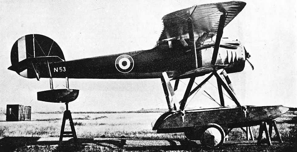
The P.V.5, N53, showing the unusual annular cowling for the 150hp Hispano-Suiza engine, somewhat reminiscent of the Sopwith Hispano Triplane.
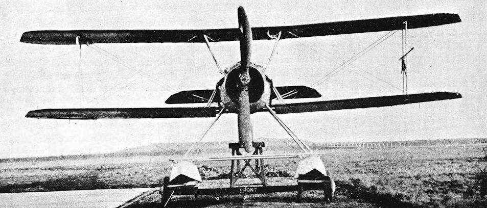
Port Victoria P.V.5a.
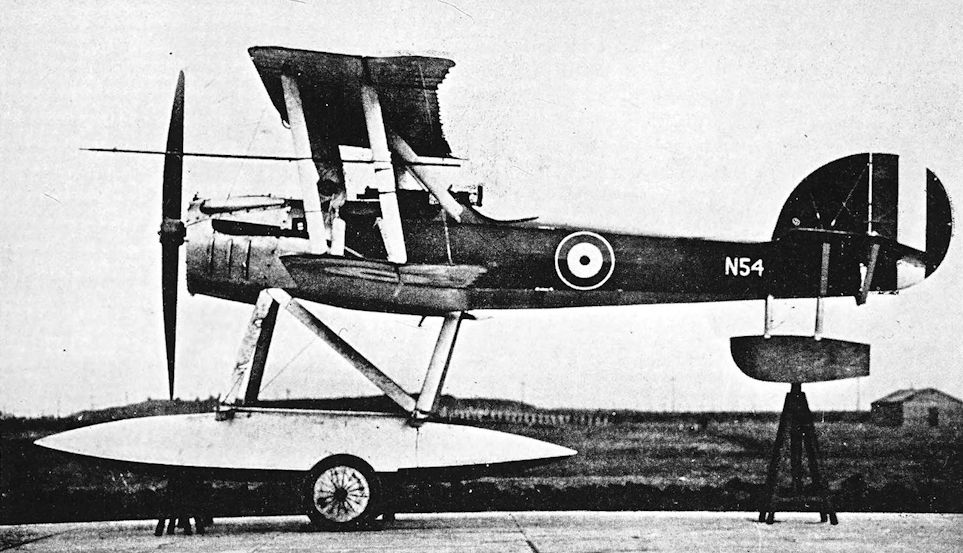
Port Victoria P.V.5a.
Port Victoria P.V.7, the Grain Kitten, and P.V.8, the Eastchurch Kitten
WHILE the P.V.5 and P.V.5a were under construction, an official request was made for the investigation of the possibility of building a small single-seat aeroplane of reasonable performance, powered by the 45 h.p. A.B.C. Gnat horizontally-opposed two-cylinder engine. The aim was to produce a machine which would be small enough to be carried by Torpedo-Boat Destroyers and similar small craft. Obviously, therefore, it had to be able to take off from a very small flying-off platform.
Both the Experimental Construction Depot, Port Victoria, and the Experimental Flight at Eastchurch were asked to tackle this problem, and both ultimately produced designs. When the work began, the Experimental Flight was commanded by Squadron Commander H. R. Busteed, who had as his Chief Technical Officer Lieutenant G. H. Millar, R.N.V.R. Lieutenant Millar was the designer of the Eastchurch machine. When Squadron Commander Busteed took over the command of Port Victoria, Lieutenant Millar accompanied him, and the partly-built Eastchurch, machine was taken to Port Victoria for completion in the workshops there.
The designation P.V.6 had been given to the design of a projected high-speed landplane scout which did not proceed beyond the preliminary layout. The little biplane designed by the Experimental Construction Depot was therefore designated P.V.7, and the Eastchurch machine was given the type number P.V.8 despite the fact that it was not a true P.V. design. Their diminutive size earned both machines the name Kitten, and for distinguishing purposes the P.V.7 was known as the Grain Kitten and the P.V.8 as the Eastchurch Kitten. Not unnaturally, the two Kittens differed markedly from each other. Like its predecessors, the Grain Kitten was a sesquiplane with wings of high-lift section and the characteristic elliptical vertical tail surfaces, but was otherwise of conventional appearance. The P.V.8, on the other hand, had rather severe lines with heavily staggered wings of equal span connected by a single broad interplane strut.
Construction of the P.V.7 was entirely conventional - in fact, novel and unusual features were deliberately avoided in its design - and it was intended that the all-up weight should not exceed 520 lb. In point of fact the completed machine, fully loaded, weighed rather less than that.
As with the P.V.4, P.V.5 and P.V.5a, so with the P.V.7 and P.V.8 the promised engines were not forthcoming. For want of the 45 h.p. geared Gnats each machine had to be considerably modified to take the 35 h.p. direct-drive Gnat instead. In both cases the engine had to be installed about six inches higher to bring the thrust line into its proper place. Both machines were completed in the summer of 1917.
The Grain Kitten was completed first. On test, it proved to be tail-heavy, the performance did not come up to expectations, and it was very difficult to handle on the ground. Unfortunately, the original aerofoil section was by no means a success and ultimately new wings of more conventional form were fitted. At the same time the tail-unit was modified to overcome the tail-heaviness and the wheels were moved forward to improve ground-handling characteristics. Whether these attempted remedies proved effective is not known, because there is no record of any subsequent flights by the Grain Kitten.
The P.V.8 design was based on a greater loaded weight than that of P.V.7, but larger wing area gave a lower wing-loading. The undercarriage had no springing: the large diameter tyres were relied upon to provide shock absorption. The lower ends of the main flying wires were anchored to the ends of the undercarriage axle, presumably to provide them with the most favourable angle possible. Ailerons were fitted to both wings, but only the upper mainplane was rigged with dihedral.
As originally built, the P.V.8 had no fixed tailplane, but was provided with a balanced elevator similar to that which was a characteristic of the earlier Morane-Saulnier monoplanes and biplanes. On its first flight, however, the machine was found to be seriously unstable longitudinally. Most of the elevator balance area was removed, leaving only a small horn balance at the tip, and a small fixed tailplane was fitted. The effect of this modification was at once beneficial, and seemed to point to overbalancing of the original elevators as the cause of the instability.
With its new tail unit, the Eastchurch Kitten proved to be remarkably successful. It was extremely easy to fly, and ultimately proved to be a much better aeroplane than the P.V.7 Grain Kitten.
The P.V.8 became quite widely but erroneously known as the “Sopwith Kitten”, and was so described even in some official publications. The misnomer is usually attributed to the plank interplane struts, which resembled those of several types of Sopwith Triplane and the tapered-wing version of the Camel. Another possibility which cannot be completely disregarded is that the Sopwith company’s practice of naming most of their products after animals may have led to the belief that the Eastchurch Kitten was another addition to the Sopwith “Zoo”.
SPECIFICATION
Manufacturers: R.N.A.S. Experimental Construction Depot, Port Victoria, Isle of Grain.
Power: 35 h.p. A.B.C. Gnat.
Dimensions: P.V.7: Span: upper 18 ft, lower 12 ft 7 in. Length: 14 ft 11 in. Height: 5 ft 3 in. Chord: upper 3ft 6 in., lower 2 ft 6 in. Gap: 3 ft. P.V.8: Span: 19ft. Length: 15 ft 7 1/2 in. Height: 5 ft 5 in. Chord: 3 ft. Gap: 3 ft.
Areas: Wings: P.V.7, 85 sq ft; P.V.8, 106 sq ft.
Armament: One Lewis machine-gun mounted above the centre-section.
Serial Numbers: P.V.7: N.539. P.V.8: N.540.
Weights (lb) and Performance:
Aircraft P.V.7 P.V.8
Date of Trial Report October 6th, 1917 October 11th, 1917
Type of airscrew used on trial Lang 2340 Lang 2340
Weight empty 284 340
Military load 30-5 30-5
Pilot 138-5 138-5
Fuel and oil 38 77
Weight loaded 491 586
Maximum speed (m.p.h.) at
2,000 ft 89 94-5
6,500 ft 85 87-5
10,000 ft 74 84
15,000 ft - 78
m. s. m. s.
Climb to
6,500 ft 10 50 11 00
10,000 ft 22 00 20 10
12,000 ft 35 00 - -
15,000 ft - - 47 00
Service ceiling (feet) 11,900 14,900
Tankage (gallons): Petrol 4 9
Oil 1 1
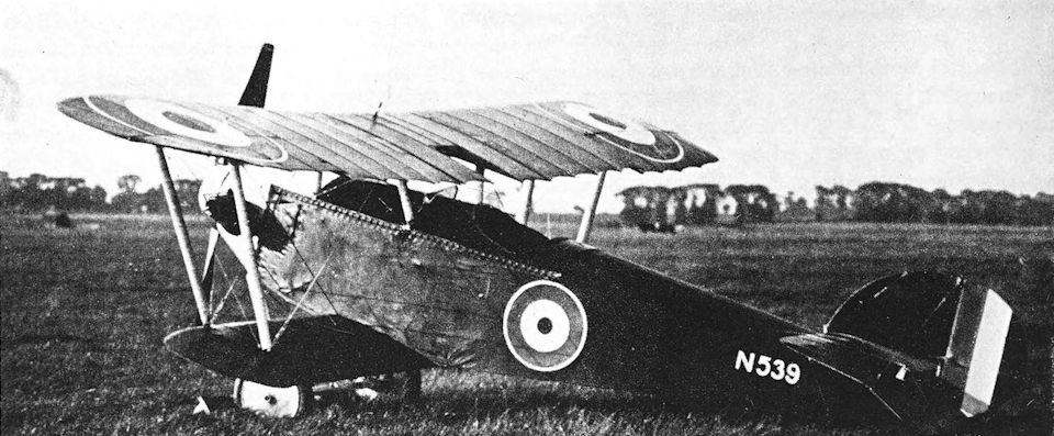
Port Victoria P.V.7, the Grain Kitten.
Port Victoria P.V.7, the Grain Kitten, and P.V.8, the Eastchurch Kitten
WHILE the P.V.5 and P.V.5a were under construction, an official request was made for the investigation of the possibility of building a small single-seat aeroplane of reasonable performance, powered by the 45 h.p. A.B.C. Gnat horizontally-opposed two-cylinder engine. The aim was to produce a machine which would be small enough to be carried by Torpedo-Boat Destroyers and similar small craft. Obviously, therefore, it had to be able to take off from a very small flying-off platform.
Both the Experimental Construction Depot, Port Victoria, and the Experimental Flight at Eastchurch were asked to tackle this problem, and both ultimately produced designs. When the work began, the Experimental Flight was commanded by Squadron Commander H. R. Busteed, who had as his Chief Technical Officer Lieutenant G. H. Millar, R.N.V.R. Lieutenant Millar was the designer of the Eastchurch machine. When Squadron Commander Busteed took over the command of Port Victoria, Lieutenant Millar accompanied him, and the partly-built Eastchurch, machine was taken to Port Victoria for completion in the workshops there.
The designation P.V.6 had been given to the design of a projected high-speed landplane scout which did not proceed beyond the preliminary layout. The little biplane designed by the Experimental Construction Depot was therefore designated P.V.7, and the Eastchurch machine was given the type number P.V.8 despite the fact that it was not a true P.V. design. Their diminutive size earned both machines the name Kitten, and for distinguishing purposes the P.V.7 was known as the Grain Kitten and the P.V.8 as the Eastchurch Kitten. Not unnaturally, the two Kittens differed markedly from each other. Like its predecessors, the Grain Kitten was a sesquiplane with wings of high-lift section and the characteristic elliptical vertical tail surfaces, but was otherwise of conventional appearance. The P.V.8, on the other hand, had rather severe lines with heavily staggered wings of equal span connected by a single broad interplane strut.
Construction of the P.V.7 was entirely conventional - in fact, novel and unusual features were deliberately avoided in its design - and it was intended that the all-up weight should not exceed 520 lb. In point of fact the completed machine, fully loaded, weighed rather less than that.
As with the P.V.4, P.V.5 and P.V.5a, so with the P.V.7 and P.V.8 the promised engines were not forthcoming. For want of the 45 h.p. geared Gnats each machine had to be considerably modified to take the 35 h.p. direct-drive Gnat instead. In both cases the engine had to be installed about six inches higher to bring the thrust line into its proper place. Both machines were completed in the summer of 1917.
The Grain Kitten was completed first. On test, it proved to be tail-heavy, the performance did not come up to expectations, and it was very difficult to handle on the ground. Unfortunately, the original aerofoil section was by no means a success and ultimately new wings of more conventional form were fitted. At the same time the tail-unit was modified to overcome the tail-heaviness and the wheels were moved forward to improve ground-handling characteristics. Whether these attempted remedies proved effective is not known, because there is no record of any subsequent flights by the Grain Kitten.
The P.V.8 design was based on a greater loaded weight than that of P.V.7, but larger wing area gave a lower wing-loading. The undercarriage had no springing: the large diameter tyres were relied upon to provide shock absorption. The lower ends of the main flying wires were anchored to the ends of the undercarriage axle, presumably to provide them with the most favourable angle possible. Ailerons were fitted to both wings, but only the upper mainplane was rigged with dihedral.
As originally built, the P.V.8 had no fixed tailplane, but was provided with a balanced elevator similar to that which was a characteristic of the earlier Morane-Saulnier monoplanes and biplanes. On its first flight, however, the machine was found to be seriously unstable longitudinally. Most of the elevator balance area was removed, leaving only a small horn balance at the tip, and a small fixed tailplane was fitted. The effect of this modification was at once beneficial, and seemed to point to overbalancing of the original elevators as the cause of the instability.
With its new tail unit, the Eastchurch Kitten proved to be remarkably successful. It was extremely easy to fly, and ultimately proved to be a much better aeroplane than the P.V.7 Grain Kitten.
The P.V.8 became quite widely but erroneously known as the “Sopwith Kitten”, and was so described even in some official publications. The misnomer is usually attributed to the plank interplane struts, which resembled those of several types of Sopwith Triplane and the tapered-wing version of the Camel. Another possibility which cannot be completely disregarded is that the Sopwith company’s practice of naming most of their products after animals may have led to the belief that the Eastchurch Kitten was another addition to the Sopwith “Zoo”.
SPECIFICATION
Manufacturers: R.N.A.S. Experimental Construction Depot, Port Victoria, Isle of Grain.
Power: 35 h.p. A.B.C. Gnat.
Dimensions: P.V.7: Span: upper 18 ft, lower 12 ft 7 in. Length: 14 ft 11 in. Height: 5 ft 3 in. Chord: upper 3ft 6 in., lower 2 ft 6 in. Gap: 3 ft. P.V.8: Span: 19ft. Length: 15 ft 7 1/2 in. Height: 5 ft 5 in. Chord: 3 ft. Gap: 3 ft.
Areas: Wings: P.V.7, 85 sq ft; P.V.8, 106 sq ft.
Armament: One Lewis machine-gun mounted above the centre-section.
Serial Numbers: P.V.7: N.539. P.V.8: N.540.
Weights (lb) and Performance:
Aircraft P.V.7 P.V.8
Date of Trial Report October 6th, 1917 October 11th, 1917
Type of airscrew used on trial Lang 2340 Lang 2340
Weight empty 284 340
Military load 30-5 30-5
Pilot 138-5 138-5
Fuel and oil 38 77
Weight loaded 491 586
Maximum speed (m.p.h.) at
2,000 ft 89 94-5
6,500 ft 85 87-5
10,000 ft 74 84
15,000 ft - 78
m. s. m. s.
Climb to
6,500 ft 10 50 11 00
10,000 ft 22 00 20 10
12,000 ft 35 00 - -
15,000 ft - - 47 00
Service ceiling (feet) 11,900 14,900
Tankage (gallons): Petrol 4 9
Oil 1 1
WHILE the P.V.5 and P.V.5a were under construction, an official request was made for the investigation of the possibility of building a small single-seat aeroplane of reasonable performance, powered by the 45 h.p. A.B.C. Gnat horizontally-opposed two-cylinder engine. The aim was to produce a machine which would be small enough to be carried by Torpedo-Boat Destroyers and similar small craft. Obviously, therefore, it had to be able to take off from a very small flying-off platform.
Both the Experimental Construction Depot, Port Victoria, and the Experimental Flight at Eastchurch were asked to tackle this problem, and both ultimately produced designs. When the work began, the Experimental Flight was commanded by Squadron Commander H. R. Busteed, who had as his Chief Technical Officer Lieutenant G. H. Millar, R.N.V.R. Lieutenant Millar was the designer of the Eastchurch machine. When Squadron Commander Busteed took over the command of Port Victoria, Lieutenant Millar accompanied him, and the partly-built Eastchurch, machine was taken to Port Victoria for completion in the workshops there.
The designation P.V.6 had been given to the design of a projected high-speed landplane scout which did not proceed beyond the preliminary layout. The little biplane designed by the Experimental Construction Depot was therefore designated P.V.7, and the Eastchurch machine was given the type number P.V.8 despite the fact that it was not a true P.V. design. Their diminutive size earned both machines the name Kitten, and for distinguishing purposes the P.V.7 was known as the Grain Kitten and the P.V.8 as the Eastchurch Kitten. Not unnaturally, the two Kittens differed markedly from each other. Like its predecessors, the Grain Kitten was a sesquiplane with wings of high-lift section and the characteristic elliptical vertical tail surfaces, but was otherwise of conventional appearance. The P.V.8, on the other hand, had rather severe lines with heavily staggered wings of equal span connected by a single broad interplane strut.
Construction of the P.V.7 was entirely conventional - in fact, novel and unusual features were deliberately avoided in its design - and it was intended that the all-up weight should not exceed 520 lb. In point of fact the completed machine, fully loaded, weighed rather less than that.
As with the P.V.4, P.V.5 and P.V.5a, so with the P.V.7 and P.V.8 the promised engines were not forthcoming. For want of the 45 h.p. geared Gnats each machine had to be considerably modified to take the 35 h.p. direct-drive Gnat instead. In both cases the engine had to be installed about six inches higher to bring the thrust line into its proper place. Both machines were completed in the summer of 1917.
The Grain Kitten was completed first. On test, it proved to be tail-heavy, the performance did not come up to expectations, and it was very difficult to handle on the ground. Unfortunately, the original aerofoil section was by no means a success and ultimately new wings of more conventional form were fitted. At the same time the tail-unit was modified to overcome the tail-heaviness and the wheels were moved forward to improve ground-handling characteristics. Whether these attempted remedies proved effective is not known, because there is no record of any subsequent flights by the Grain Kitten.
The P.V.8 design was based on a greater loaded weight than that of P.V.7, but larger wing area gave a lower wing-loading. The undercarriage had no springing: the large diameter tyres were relied upon to provide shock absorption. The lower ends of the main flying wires were anchored to the ends of the undercarriage axle, presumably to provide them with the most favourable angle possible. Ailerons were fitted to both wings, but only the upper mainplane was rigged with dihedral.
As originally built, the P.V.8 had no fixed tailplane, but was provided with a balanced elevator similar to that which was a characteristic of the earlier Morane-Saulnier monoplanes and biplanes. On its first flight, however, the machine was found to be seriously unstable longitudinally. Most of the elevator balance area was removed, leaving only a small horn balance at the tip, and a small fixed tailplane was fitted. The effect of this modification was at once beneficial, and seemed to point to overbalancing of the original elevators as the cause of the instability.
With its new tail unit, the Eastchurch Kitten proved to be remarkably successful. It was extremely easy to fly, and ultimately proved to be a much better aeroplane than the P.V.7 Grain Kitten.
The P.V.8 became quite widely but erroneously known as the “Sopwith Kitten”, and was so described even in some official publications. The misnomer is usually attributed to the plank interplane struts, which resembled those of several types of Sopwith Triplane and the tapered-wing version of the Camel. Another possibility which cannot be completely disregarded is that the Sopwith company’s practice of naming most of their products after animals may have led to the belief that the Eastchurch Kitten was another addition to the Sopwith “Zoo”.
SPECIFICATION
Manufacturers: R.N.A.S. Experimental Construction Depot, Port Victoria, Isle of Grain.
Power: 35 h.p. A.B.C. Gnat.
Dimensions: P.V.7: Span: upper 18 ft, lower 12 ft 7 in. Length: 14 ft 11 in. Height: 5 ft 3 in. Chord: upper 3ft 6 in., lower 2 ft 6 in. Gap: 3 ft. P.V.8: Span: 19ft. Length: 15 ft 7 1/2 in. Height: 5 ft 5 in. Chord: 3 ft. Gap: 3 ft.
Areas: Wings: P.V.7, 85 sq ft; P.V.8, 106 sq ft.
Armament: One Lewis machine-gun mounted above the centre-section.
Serial Numbers: P.V.7: N.539. P.V.8: N.540.
Weights (lb) and Performance:
Aircraft P.V.7 P.V.8
Date of Trial Report October 6th, 1917 October 11th, 1917
Type of airscrew used on trial Lang 2340 Lang 2340
Weight empty 284 340
Military load 30-5 30-5
Pilot 138-5 138-5
Fuel and oil 38 77
Weight loaded 491 586
Maximum speed (m.p.h.) at
2,000 ft 89 94-5
6,500 ft 85 87-5
10,000 ft 74 84
15,000 ft - 78
m. s. m. s.
Climb to
6,500 ft 10 50 11 00
10,000 ft 22 00 20 10
12,000 ft 35 00 - -
15,000 ft - - 47 00
Service ceiling (feet) 11,900 14,900
Tankage (gallons): Petrol 4 9
Oil 1 1

Port Victoria P.V.8, the Eastchurch Kitten. The P.V.8 in its original form with balanced elevator and no tailplane.

The Eastchurch Kitten, N540, after the addition of a fixed tailplane; note the ailerons on upper and lower wings. The Lewis gun could not be fired at the angle shown here as it was not synchronized.
Port Victoria P.V.9
WHILE the Kittens were being built, Port Victoria was instructed to design a single-seat fighter seaplane in the same category as the P.V.2. It was stipulated that the new aircraft was to have the good handling qualities of the P.V.2, the same excellent outlook from the cockpit, and a really worthwhile maximum speed.
In response to this request the design staff at Port Victoria brought out the design known as P.V.9, based on a 130 h.p. Clerget rotary engine. A high wing-loading was envisaged, and it was intended to use a high-lift aerofoil.
Official prejudice against high-lift wings led to the rejection of the original design, and instructions were given that the R.A.F. 15 aerofoil was to be used. Port Victoria promptly objected on the grounds that, within the specified dimensions, use of R.A.F. 15 would mean a poorer rate of climb and a higher landing speed. These protests proved unavailing, and the aeroplane which was eventually built was considerably larger and heavier than the original concept.
The P.V.9 bore a general resemblance to the P.V.2, for it was a sesquiplane braced entirely by faired steel tubes. The later machine had a vee-strut between each float and each lower mainplane. The fuselage was a clean, conventional structure which was mounted between the wings yet filled almost the whole gap; the proximity of the upper wing to the fuselage ensured a good all-round view for the pilot. The main fuel tanks were installed on each side of the fuselage within the fairings behind the engine cowling: the tanks were thus outside the basic fuselage structure, and a commodious cockpit was thereby provided in a small fuselage. A pair of Linton Hope floats were designed for the P.V.9 but were never built. The completed machine had pontoon-type floats, each with a single step, and a streamlined tail-float of circular cross-section.
The P.V.9 made its first flight in December, 1917, powered by a 150 h.p. B.R.1 engine. Persistent and protracted engine trouble prevented the carrying out of flight trials until May, 1918; and even then truly representative performance figures could not be obtained because a suitable airscrew was not available. The machine was tested with one taken from a lighter and faster landplane (probably a Sopwith Camel), but it was by no means suitable for the P.V.9. It did not allow the engine to develop its full r.p.m. and caused a marked drop in r.p.m. above 2,000 ft. This had an adverse effect on speed and rate of climb, and reduced the ceiling by several thousands of feet.
In spite of all the official interference and subsequent difficulties, the P.V.9 was reported to be the best single-seat seaplane fighter built up to the time of its trials. By then, however, the machine fulfilled no known Service requirement and was apparently shelved.
SPECIFICATION
Manufacturers: R.N.A.S. Experimental Construction Depot, Port Victoria, Isle of Grain.
Power: 150 h.p. Bentley B.R.1.
Dimensions: Span: upper 30 ft 11 in., lower 20 ft 1 in. Length: 25 ft 2 in. Height: 9 ft. Chord: upper 5 ft 6 in., lower 3 ft 9 in. Gap: 4 ft. Span of tail: 11 ft 6 in. Airscrew diameter: 9 ft.
Areas: Wings: 227 sq ft.
Weights and Performance: No. of Trial Report: N.M.178. Date of Trial Report: May 27th, 1918. Type of airscrew used on trial: A.B.644. Weight empty: 1,404 lb. Military load: 120 lb. Pilot: 180 lb. Fuel and oil: 261 lb. Loaded: 1,965 lb. Maximum speed at 2,000 ft: 110-5 m.p.h.; at 6,500 ft: 105 m.p.h.; at 10,000 ft: 99-5 m.p.h. Climb to 2,000 ft: 3 min 10 sec; to 6,500 ft: 13 min 20 sec; to 10,000 ft: 27 min 20 sec. Service ceiling: 11,500 ft. Endurance: 2 1/2 hours.
Tankage: Petrol: 34-5 gallons. Oil: 6 gallons.
Armament: One fixed forward-firing Vickers machine-gun mounted on top of the fuselage and synchronised to fire through the revolving airscrew; one Lewis machine-gun above the centre-section firing forwards and upwards over the airscrew.
Serial Number: N.55.

Delayed by engine difficulties, the P.V.9 was discontinued in the summer of 1918.
Grain Griffin
WHILE the P.V.9 was being constructed, a Sopwith B.1 single-seat bomber was delivered to Port Victoria. Instructions were issued that it was to be converted into a two-seat fleet reconnaissance machine, fitted with wireless and folding wings. The job was regarded as urgent, but in spite of that the Sopwith machine was delivered without a radiator and could not be flown for some time after its arrival at Grain.
The Sopwith bomber was accompanied by its performance figures which, established at Martlesham Heath with a large load of bombs, were highly creditable. So good were the performance figures, in fact, that they gave rise to a good deal of conjecture as to why the aeroplane was not used for its designed purpose.
The task of modifying the B.1 as required proved to be no easy matter. Its fuselage was comparatively slender and was not wide enough to accommodate the wireless installation, and the position of the outer interplane struts was such that they would foul the tailplane if the wings were folded. The Port Victoria design staff reported that it would be quicker and more satisfactory to design and build a new machine based on the Sopwith than to attempt to modify the original and produce a hybrid of doubtful value.
Permission was granted for work on the new design, but the modification of the original machine was carried out at the same time.
The modified aircraft was N.50. The pilot’s cockpit remained in its original position under the centresection, and a second cockpit for the observer was provided just behind the rear centre-section struts. The original narrow centre-section, borne on vertical struts, was retained; but the wing span had to be slightly reduced to enable the outer pair of interplane struts to clear the tailplane with the wings folded. The ailerons of N.50 were narrower than those of the original Sopwith B.1, and were hinged to an auxiliary spar some inches behind the rear spar. The engine was a 200 h.p. Hispano-Suiza; and a large hydrovane was fitted to the undercarriage forward of the wheels.
These modifications were severely detrimental to the machine’s performance, and the ailerons proved to be virtually ineffective as control surfaces.
By this time, design work was well advanced on the redesigned machine, which had been christened Griffin: six prototypes had been ordered. From the drawings for the new wings a set of mainplanes were made and fitted to the original fuselage. It is uncertain whether these wings included the wider centresection fitted to the Griffins proper, but the disposition of the bracing bays had been changed in such a way that the outer interplane struts cleared the tailplane when the wings were folded. The span was not reduced, however.
The original universally-jointed control column was replaced by one with wheel control for the ailerons, and on test it was found that the machine had regained much of its lost performance.
The true Griffins (that is, the machines built throughout to the revised design) had a wider fuselage and a considerably wider centre-section; consequently the span of the Griffin was 3 feet greater than that of the Sopwith B.1. In end elevation the centre-section struts were raked outwards, and the lower centre-section was braced by struts to the upper longerons of the fuselage.
The first Griffin was N.100. This machine was powered by the 200 h.p. Sunbeam Arab, and had no hydrovane on the undercarriage. At first, plain ailerons were fitted, and were full-width surfaces hinged to the rear spar. Lateral control was still unsatisfactory, however, and horn-balanced ailerons were substituted: these cured the trouble. The engine installation also underwent detail modification at about this time.
The original Sopwith-designed rudder was fitted to N.50 and, at first, to N.100. A horn-balanced surface of increased area was later introduced. The second true Griffin, N.101, was fitted with the 230 h.p. Bentley B.R.2 rotary engine in place of the Arab: the use of the alternative engine may have been prompted by trouble with the Arab.
The Griffins were flown a good deal, but none saw operational service and the type was abandoned late in 1918. It was the last aeroplane to be produced by the Experimental Construction Depot.
SPECIFICATION
Manufacturers: R.N.A.S. Experimental Construction Depot, Port Victoria, Isle of Grain.
Power: N.50: 200 h.p. Hispano-Suiza. Grain Griffin: 200 h.p. Sunbeam Arab; 230 h.p. Bentley B.R.2.
Dimensions: Span: 42 ft 6 in. Length: Arab, 27 ft 3 in.; B.R.2, 27 ft 6 in. Height: Arab, 10 ft 6 in.; B.R.2, 10 ft. Chord: 6 ft 3 in.
Areas: Wings: 506 sq ft.
Tankage: Petrol: 50 gallons. Oil: 5 gallons.
Armament: One Lewis machine-gun on movable mounting behind rear cockpit.
Serial Numbers: N.50; N.100-N.106.
Weights (lb) and Performance:
Engine Arab B.R.2
No. of Trial Report N.M. 195 M.209
Date of Trial Report June 29th, 1918 June, 1918
Type of airscrew used on trial A.B.8212 Lang 4040
Weight empty 1,911 1,675
Military load 178 346
Grew 360 360
Fuel and oil 409 477
Weight loaded 2,858 2,858
Maximum speed (m.p.h.) at
5,000 ft 115 -
6,500 ft 113 112-5
10,000 ft 108-5 108
15,000 ft 101 99
m. s. m. s.
Climb to
6,500 ft 7 05 9 00
10,000 ft 12 00 15 55
15,000 ft 23 30 33 40
Service ceiling (feet) 19,000 16,500
Endurance (hours) 3 5 1/2

Grain Griffin. N.50, the aeroplane from which the Griffin design was developed. This aircraft had upright centre-section struts, hydrovanes on the undercarriage, narrow-chord ailerons, and a 200 h.p. Hispano-Suiza engine.

Grain Griffin with Bentley B.R.2 engine.

The third Griffin, N.102, had plain stub exhausts and a modified cowling. This illustration shows the observer’s Lewis gun and the final form of rudder.

Griffin with modified Sunbeam Arab installation, horn-balanced rudder and horn-balanced ailerons.
Porte Baby
WHILE the experiments with the Curtiss America hulls were proceeding, Squadron Commander Porte used the experience gained from them to design a large three-engined flying boat. Construction was begun before the F.1 was tested, so the design of the large machine was based only on the results obtained from the four predecessors of the F.1. The new aircraft, No. 9800, was at once ironically dubbed Baby or H.M.S. Baby, on account of its great size.
The precise origin of the Porte Baby is rendered somewhat obscure by the aircraft’s obvious relationship to another large three-engined boat which was described as a Curtiss in the 1917 edition of Jane’s All the World’s Aircraft. The so-called Curtiss had three pusher engines, and illustrations in the 1917 Jane’s were reproduced from photographs which appeared to have been made at Felixstowe. The big three-pusher flying boat and the Baby had so many common features that it is impossible to overlook the possibility that the “Curtiss” may in fact have been the Baby in its original form.
However that may be, the Baby has always been depicted with its two outboard engines driving tractor airscrews whilst the central power unit alone was a pusher. The engines were three of the big Rolls-Royce vee-twelves of the type which was to become known as the Eagle, and delivered 250 h.p. each. The Baby’s plywood-covered hull was 56 feet 10 inches long, and incorporated an enclosed cabin for the pilots; there was one step under the centre of gravity. The wings were of unequal span, and were similarly disposed to those of the Curtiss America, with long extensions on the upper wing. All bracing was by stranded cables.
On trial, it was found that the Porte Baby wallowed rather badly in a following sea, but this defect was overcome by lengthening the bows by three feet; the water performance was thereafter much improved. The machine was underpowered for its size, but the maximum speed of 78 m.p.h. was by no means bad in the circumstances.
By this time, however, the results obtained from the Porte I hull had become available and had been utilised to produce the Porte II or F.2 flying boat, which was clearly so much superior to the Porte Baby that development of the three-engined machine was not pursued. Twenty production Babies were ordered from the Aircraft Manufacturing Company, however, construction being undertaken by that firm’s subsidiary company, May, Harden & May of Southampton Water. Only ten, numbered 9801-9810, were completed, but it seems that some at least of the other ten hulls were built.
These production machines differed slightly from the prototype. No. 9800 had originally had a diamond-shaped structure of four struts at the rear of the outboard engines, but was later modified to have an improved engine installation in which a normal straight interplane strut was fitted between the rear spars of the upper and lower mainplanes in line with the engines. All production Babies incorporated this modification. Although it has been customary to regard the standard power plant of the Porte Baby as consisting of three Rolls-Royce engines, some at least (e.g., 9801) had a 260 h.p. Green as the central engine. Like the Rolls-Royce, the big Green was a water-cooled vee-twelve.
The performance of the later production Babies benefited from the installation of three Rolls-Royce Eagles of later marks: at least one had three Eagle VIIIs. By the time No. 9810 appeared neater radiators, similar to those of the later F-boats, were fitted; and on this Baby the outboard engines drove two-bladed left-hand airscrews, whereas the corresponding power units on other machines drove opposite-handed four-bladed airscrews. The nose of No. 9810 was lengthened, and a bow cockpit was provided.
The Porte Baby flying boats were used operationally from Felixstowe and Killingholme, and two were still on charge with the R.A.F. at the end of October, 1918. These big boats were vulnerable because of their low speed and lack of manoeuvrability. One of them was attacked by two enemy seaplanes and a landplane near the North Hinder Light Vessel shortly after 4 p.m. on October 1st, 1917, and a running fight was carried on for some twenty minutes. Normally, the operational crew of a Baby was five men, but on this occasion there were six on board; the pilots were Flight Commander N. Sholto Douglas and Flight-Lieutenant B. D. Hobbs. When the Baby was attacked, Hobbs was at the controls, and he skilfully avoided many of the enemy attacks. Ultimately the boat was forced down with its centre and port engines shot about, and while on the water it was machine-gunned by the enemy seaplanes.
When the enemy machines had gone, the crew of the Baby managed to repair the damaged engines sufficiently to enable the boat to be taxied slowly towards the English coast, and by 1.30 a.m. on October and it reached Sizewell Gap, north of Orfordness. It was towed back to Felixstowe that morning. This experience led to the decision that the Porte Baby flying boats should not be used in areas where they might be attacked unless an escort of Curtiss H.12 or F.2A flying boats could be provided.
The prototype Baby, No. 9800, was experimentally armed with a six-pounder Davis non-recoil gun, presumably for anti-submarine work, but there is no record that it was ever in action. A Baby (again almost certainly No. 9800) was also used in torpedo-carrying experiments: in April, 1916, it flew with two 14-inch torpedoes, one under each lower wing.
In the history of the Bristol Scout it has already been related how, on May 17th, 1916, an aeroplane of that type was mounted on the upper wing of a Porte Baby, taken into the air by the flying boat, and launched at a height of 1,000 feet over Harwich. At that early date the Baby could only have been the prototype.
SPECIFICATION
Manufacturers: Seaplane Experimental Station, Felixstowe.
Contractors: The Aircraft Manufacturing Co., Ltd., Hendon, construction by May, Harden & May, Southampton Water.
Power: Prototype: three 250 h.p. Rolls-Royce. Production: some had two 250 h.p. Rolls-Royce and one 260 h.p. Green; ultimately three 325 h.p. Rolls-Royce Eagle VIIs or 360 h.p. Eagle VIIIs were fitted.
Dimensions: Span: 124 ft. Length: 63 ft. Length of hull only: 56 ft 10 in. Height: 25 ft. Beam at step: 14 ft.
Areas: Wings: 2,364 sq ft.
Weights: Production machine: Empty: 14,700 lb. Military load: 298 lb. Crew: 1,120 lb. Fuel and oil: 2,482 lb. Weight loaded: 18,600 lb.
Performance: Prototype: maximum speed: 78 m.p.h. Climb to 3,000 ft: 20 min. Production - Eagle VIII engines (from Trial Report No. N.M.129, dated March 12th, 1918): maximum speed at sea level: 92 m.p.h.; at 2,000 ft: 87-5 m.p.h.; at 6,500 ft: 72 m.p.h. Climb to 2,000 ft: 5 min 20 sec; to 6,500 ft: 25 min 05 sec. Service ceiling: 8,000 ft.
Armament: Machine-guns were carried, presumably on mountings in the hatchway immediately behind the pilots’ cockpit, and probably behind the wings. The prototype had a six-pounder Davis gun mounted on the bows, and was also used in torpedo-carrying experiments.
Service Use: R.N.A.S. Stations at Felixstowe and Killingholme.
Production and Allocation: The prototype and ten production Babies were built; some additional hulls may also have been made. Two Babies were still on charge with the R.A.F. on October 31st, 1918.
Serial Numbers: 9800-9820. Only 9800-9810 were delivered complete.
Notes on Individual Machines: 9800: officially accepted at Felixstowe, November 2nd, 1916. 9801: officially accepted on March 27th, 1917; written off at Killingholme January 9th, 1918. 9802: officially accepted at Felixstowe on July 16th, 1917. 9805-9809 were officially accepted at Killingholme. 9806 was in store on September 12th, 1918; 9807 was at a Fleet Base on October 14th, 1918. 9808 and 9809 were in store in September, 1918.

Porte Baby with Davis gun mounted on bows.

Porte Baby. The “composite” experiment, with the Bristol Scout C, No. 3028, on the upper wing of a Porte Baby flying boat. Porte thought that this method of attacking Zeppelins had great promise and it was "a great pity in the light of after experience that this scheme was not used in actual service."

The last Porte Baby, No. 9810, with improved engine installations and lengthened forebody.
B.E.1
IN January, 1911, the first aeroplane designed throughout at the Balloon Factory was built by ostensibly reconstructing a crashed Bleriot monoplane: the result of the “reconstruction” was the S.E.1. It was only by recourse to such devices that the staff at Farnborough could construct aeroplanes of their own design, for the Factory had neither funds nor authority for the construction of aircraft.
A similar opportunity presented itself in April, 1911, when a Voisin pusher biplane with a 60 h.p. Wolseley engine was sent to Farnborough for repair: it had originally been presented to the War Office by the Duke of Westminster. The opportunity was taken to build a two-seat tractor biplane to the designs of F. M. Green and Geoffrey de Havilland.
The aircraft which emerged was the first to fall into the B.E. category and was consequently named B.E.1. At first the B.E.1 had the same Wolseley engine which had been installed in the Voisin. A rather sketchy cowling was fitted to the engine, and a large rectangular radiator was mounted between the forward centre-section struts. Soon, however, the Wolseley was replaced by a 60 h.p. Renault, and the last link with the Voisin machine was severed. These vee-eight engines were so quiet in comparison with the contemporary rotaries that the B.E.1 was known as the Silent Aeroplane.
The B.E.1 showed much advanced aerodynamic and structural thinking. The fuselage was a cross-braced wooden box-girder, fabric covered and with a rounded top-decking behind the long undivided cockpit. The ear-shaped rudder was mounted on the extended sternpost; there was no fin. The wings were of unequal span, and warping was used for lateral control. Fuel was carried in a gravity tank slung under the centre-section.
For three years the B.E.1 gave valuable and varied service, and participated in many experiments. In the course of these it suffered many mishaps and underwent many repairs. Its undercarriage bore the brunt of most of the crashes and had to be replaced frequently.
Apart from the testing of several experimental devices, the B.E.1 was the vehicle used for testing one of the earliest installations of wireless equipment in an aeroplane. Captain H. P. T. Lefroy, R.E., who in October, 1909, had been given charge of all experimental work in wireless telegraphy for the Army, devoted a good deal of time in the summer of 1911 to collaborating with R. Widdington in the design of a transmitter for use in aeroplanes. When completed, the transmitter was installed in the B.E.1 and tested in the air by Captain Lefroy; Geoffrey de Havilland flew the aircraft on this occasion.
In March, 1912, the B.E.1 was handed over to the Air Battalion and was assigned to Captain C. J. Burke. When the Royal Flying Corps was formed a few weeks later the machine was part of the equipment of No. 2 Squadron of which Major Burke became the Commanding Officer. The B.E.1 later received the official serial number 201, and was well-known to the officers of the infant R.F.C., officers whose names were to become part of the tradition of the new service: Brancker, Brooke-Popham, Longcroft, Sykes, Ashmore.
A distinction which can be claimed for the B.E.1 is that it was the first British aeroplane in respect of which a document roughly equivalent to a certificate of airworthiness was issued. This was dated March 14th, 1912.
In May, 1912, Captain Lefroy installed a generator in the B.E.1; it was driven from the engine crankshaft by a length of bicycle-chain running on sprockets.
The B.E.1 continued to be used at Farnborough and Netheravon until it was finally written off in a crash in January, 1915. Its epitaph was written several years later by Sir Walter Raleigh in Vol. I of The War in the Air: “The first machine of its type, it outlived generations of its successors, and before it yielded to fate had become the revered grandfather of the whole brood of Factory aeroplanes”.
SPECIFICATION
Manufacturers: The Royal Aircraft Factory, Farnborough, Hants.
Power: 60 h.p. Wolseley; 60 h.p. Renault.
Performance: Maximum speed: 59 m.p.h. Climb to 600 ft: 3 min 54 sec.
Service Use: Flown by the Air Battalion, R.E., and later by No. 2 Squadron, R.F.C., at Farnborough; later flown at Netheravon.
Serial Number: 201.
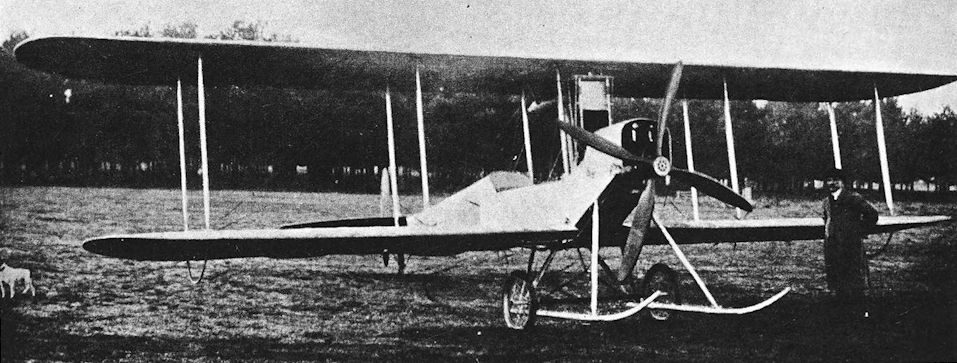
The B.E.1 in its original form with 60 h.p. Wolseley engine.
THE S.E. series began nominally with a peculiar canard biplane which appeared in 1911. It was named Santos Experimental No. 1, or S.E.1, after Santos Dumont; for the great Brazilian pioneer was regarded as the originator of the tail-first arrangement. The S.E.1 crashed on August 18th, 1911.
B.E.2, 2a and 2b
THE first B.E.2 appeared early in 1912. There was little to distinguish it from the B.E.1, for the differences lay in details only. Indeed, it is possible that the designation signified that the particular aircraft was the second aeroplane in the B.E. category rather than that it was a distinct and separate type from the B.E.1. Similar considerations probably applied in the cases of the aeroplanes which became known as the B.E.3, 4, 5, 6 and 7, and what may have been merely sequence numbers came to be used as type numbers. However that may be, the design of B.E. No. 2 became standardised as the B.E.2, and the type was produced in small numbers.
The B.E.2 was powered by the more powerful 70 h.p. Renault engine, but the basic airframe was similar to that of the B.E.1. The fuselage was unchanged, but the top-decking behind the cockpit was shortened by one bay and the fairleads for the rudder cables were brought forward a corresponding distance.
The tailplane and elevators of the B.E.2 were of greater area, and the mainplanes were rigged with a small dihedral angle; the upper wing was of slightly greater span than the lower. The undercarriage was again of the twin-skid type, but the skids were shorter and radius rods were fitted to prevent longitudinal movement of the axle.
Some of the earliest B.E.2s were produced by “rebuilding” other crashed aeroplanes, and at first there was no real standardisation. The 70 h.p. Renault was the engine normally fitted, but B.E.2 No. 205 had a 60 h.p. E.N.V. at one time. The later B.E.2s had wings of equal span, and separate cockpits were provided for the crew by the addition of a short length of decking between the seats. A gravity fuel tank was mounted under the centre-section. The observer, who occupied the front seat, was almost completely exposed, for there was no cowling or decking behind the engine.
The usual wooden construction was used throughout, apart from the outlines of the elevators and the complete rudder, which were made of steel tubing.
In May, 1912, King George V visited Farnborough and inspected the Military Wing of the R.F.C.: on this occasion B.E. machines were flown before the King. On August 12th of that year, Geoffrey de Havilland broke the British altitude record by flying a B.E.2 to 10,560 feet with Major F. H. Sykes as passenger. The B.E. reached that height in about 45 minutes.
This flight alone was convincing evidence of the machine’s quality, but a few days later it was put through some of the official tests which constituted the 1912 Military Trials. The Trials were intended to select the aeroplane best suited to the requirements of the R.F.C., and were on competitive lines. They were flown off at Salisbury Plain.
The B.E.2 was flown hors contours by Geoffrey de Havilland: having been built at the Royal Aircraft Factory it was not eligible to compete in the Trials. Its performance in these trials showed that it was the best all-round machine there; better in all important respects than the Cody biplane which was declared the winner of the competition, but which owed its success to its 120 h.p. Austro-Daimler engine and not to any excellence of design.
The B.E.2 was built in some numbers for the equipment of the R.F.C. Only a handful were made at the Royal Aircraft Factory itself, and the majority were made by Handley Page, Ltd., Hewlett and Blondeau, Ltd., and Vickers, Ltd.
Late in 1912 the B.E.2a appeared. This variant had a revised fuel system, and decking was fitted behind the engine: it enclosed the tank which was installed there and gave the observer some protection from the elements and the regurgitations of the Renault. There was no gravity tank under the centresection. Stronger interplane struts were fitted, but otherwise the airframe was unchanged.
The early B.Es gave excellent service with the R.F.C. and R.N.A.S., but official records seldom distinguish the B.E.2a from the B.E.2. When No. 2 Squadron was sent from Farnborough to Montrose, where it was to work as an independent unit, two of its B.Es were flown all the way by Captain J. H. W. Becke and Lieutenant C. A. Longcroft. The flight began on February 17th, 1913, and ended on February 26th. In August, 1913, Captain Longcroft flew from Farnborough to Montrose in one day with Lieutenant-Colonel Sykes as his passenger. For this flight his B.E.2a was fitted with an auxiliary fuel tank under the passenger’s seat.
Three months later, on November 22nd, 1913, Longcroft flew B.E.2a No. 218 from Montrose to Portsmouth and back to Farnborough non-stop. The flight was accomplished in 7 hours 20 minutes, and the total distance covered was about 650 miles. The B.E. was flown solo, for the faired-over front cockpit contained a special fuel tank designed and installed by First Class Air Mechanic H. C. S. Bullock: this tank held fuel for eight hours’ flying.
Many experiments were carried out on B.E.2s and 2a’s. Much pioneering work with oleo undercarriages was done on the type, notably with B.E.2 No. 206. In September, 1912, still with its oleo undercarriage, it was handed over to No. 2 Squadron. Five months later it was transferred to No. 4 Squadron, after which it was fitted with the standard twin-skid undercarriage. Throughout 1913 and 1914, No. 206 was flown extensively, and on December 18th, 1914, it was sent to France to join No. 6 Squadron. In the summer of 1915 it was fitted with a vee undercarriage of the B.E.2C type and survived until September of that year, when it was written off in a crash.
The oleo undercarriages which were fitted to various B.E.2s and 2a’s varied in appearance. Some were simple variants of the twin-skid layout, but one machine had an undercarriage similar to that of the F.E.2b and R.E.7; this B.E. also had a modified tail unit.
Experiments in stability were conducted with B.E.2a’s. At one time No. 601 had two fin surfaces above the centre-section and a high aspect-ratio tailplane which was braced from a central kingpost. The pilot’s cockpit was later fitted with an unusually large windscreen.
The wireless experiments which had been started in 1912 on the B.E.1 continued with B.E.2s. In 1913, just before the Army manoeuvres, Lieutenant B.T. James succeeded in receiving wireless signals with the engine of his B.E. running at full throttle. In June, 1914, he and Lieutenant D. S. Lewis flew from Netheravon to Bournemouth in two B.Es: each machine carried transmitting and receiving apparatus. The B.Es flew about ten miles apart and kept in communication with each other throughout the flight.
Work of this kind naturally stood the R.F.C. in good stead when war broke out. Four squadrons took the field, of which two (Nos. 2 and 4) were equipped throughout with B.Es. The first British aeroplane to land on the Continent after the outbreak of war was a B.E.2a of No. 2 Squadron. Flown by Lieutenant H. D. Harvey-Kelly, B.E.2a No. 347 left Dover at 6.25 a.m. on August 13th, 1914, and landed near Amiens at 8.20 a.m.
A few other B.Es were taken to France by the Aircraft Park, and three were among the equipment of Wing Commander C. R. Samson’s squadron of the R.N.A.S. which went to France on August 27th, 1914. One of the three was Samson’s own B.E.2a, No. 50, which gave long and faithful service from the time of its delivery in January, 1914, until January, 1916. During those two years, No. 50 had waged war in France and at the Dardanelles with that offensive spirit which typified Samson. This B.E. found an honoured resting place on Imbros, whence it had flown so often on its warlike occasions; for when No. 3 Wing of the R.N.A.S. returned to England, old No. 50 was condemned as unfit to travel and was broken up.
In France, the B.Es were used for reconnaissance duties; indeed one of the first reconnaissance flights after the arrival of the R.F.C. in France was made by Lieutenant G. W. Mappiebeck of No. 4 Squadron, flying a B.E.2a. As the war progressed bombs were carried. On March i ith, 1915, three B.E.2S of No. 4 Squadron set out to attack a railway junction at Lille, but none returned to the squadron’s aerodrome: engine failure brought all three down.
The first Victoria Cross to be won by a member of the British flying services was posthumously awarded to Second Lieutenant W. B. Rhodes-Moorhouse of No. 2 Squadron for his bombing attack on Courtrai railway station on April 26th, 1915. He brought his B.E.2 down to 300 feet to drop his 100-lb bomb on the line west of the station, but was mortally wounded by ground fire. Although in great pain, he flew his B.E. back to his own aerodrome at Merville in order to make his report: there were other, nearer aerodromes where he could have landed, and he was wounded twice more on his return flight. Next day, before he could know of the recognition of his superb gallantry, he died of his wounds.
The B.E.2a was used in small numbers in other parts of the world. Two, of which No. 50 was one, went to the Dardanelles with No. 3 Wing of the R.N.A.S.: the other machine was composed of components of three different B.Es, but Wing Commander Samson described it as “a real good machine.”
B.E.2a’s had been sent to Australia and India in 1914, and one of the machines from the Indian Flying School at Sitapur was sent to Egypt in December, 1914, as part of the equipment provided for the reinforcement of the Ismailia Flight of the R.F.C. In company with two Maurice Farmans this B.E.2a bombed El Murra on April 16th, 1915.
During 1914, the basic design was further improved and a version of the B.E.2 appeared with a new fuselage. This variant was designated B.E.2b and was distinguishable by its improved top-decking, which was fuller and gave better protection to the crew. Revised rudder and elevator controls were also installed, and late B.E.2b’s had ailerons for lateral control. Some had plain vee undercarriages: one machine which was thus equipped was No. 2778, which also had a cowling on the sump of its engine.
As fighting in the air developed throughout 1915, the early B.E.2s became progressively more ineffective as military aircraft. The type was never designed to carry a machine-gun, and was easily outclassed in combat. By September 25th, 1915, the R.F.C. in France had only two B.E.2a’s and four B.E.2b’s on its strength, and the type was completely withdrawn soon afterwards.
After being retired from operational service, the B.Es were quite widely used at training aerodromes.
SPECIFICATION
Manufacturers: The Royal Aircraft Factory, Farnborough, Hants.
Other Contractors: Sir W. G. Armstrong, Whitworth & Co., Ltd., Gosforth, Newcastle-on-Tyne; The British and Colonial Aeroplane Co., Ltd., Filton, Bristol; the Coventry Ordnance Works, Ltd., Coventry; Handley Page, Ltd., no Cricklewood Lane, London, N.W.; Hewlett & Blondeau, Ltd., Clapham, London; Vickers, Ltd. (Aviation Department), Imperial Court, Basil Street, Knightsbridge, London, S.W.; Whitehead Aircraft Ltd., Richmond, Surrey.
Power: 70 h.p. Renault. One B.E.2 had the 60 h.p. E.N.V. engine.
Dimensions: Span: upper 38 ft 7 1/2 in., later 35 ft 0 1/2 in.; lower 35 ft 0 1/2 in. Length: 29 ft 6 1/2 in. Incidence: 3. Span of tail: 12 ft. Wheel track: 6 ft 2 in. Airscrew diameter: 8 ft 10 in.
Areas: Wings: upper 202 sq ft, later 180 sq ft; lower 172 sq ft; total 374 sq ft, later 352 sq ft. Tailplane: 52 sq ft. Elevators: 25 sq ft. Rudder: 12 sq ft.
Weights: Empty: B.E.2a, 1,274 lb. Loaded: B.E.2, 1,650 lb; B.E.2a, 1,600 lb.
Performance: B.E.2a: Maximum speed at ground level: 70 m.p.h.; at 6,500 ft: 65 m.p.h. Climb to 3,000 ft: 9 min; to 7,000 ft: 35 min. Service ceiling: 10,000 ft. Endurance: 3 hours.
Armament: One 100-lb bomb or equivalent weight of smaller bombs; hand grenades were also carried. Rifles, pistols and carbines were carried as defensive weapons.
Service Use: Western Front: R.F.C. Squadrons Nos. 2, 4, 6, 8, 9, 12, and 16; R.N.A.S. Squadron at Dunkerque. Aegean: No. 3 Wing, R.N.A.S., Tenedos and Mudros. India: Indian Flying School, Sitapur. Egypt: Ismailia Flight, R.F.C. Australia: Flying School at Point Cook. Training: various training units, including Central Flying School, Upavon, and training squadrons at Gosport, Stirling, Wye and Wyton.
Production and Allocation: The total production is not known. The British and Colonial Aeroplane Co. built nineteen
B.E.2a’s and six B.E.2b’s. The R.N.A.S. had five B.E.2s and 132 were delivered to the R.F.C., as follows: 2a’s at the outbreak of war, and a total of 132 were delivered to the R.F.C., as follows:
B.E.2 B.E.2a B.E.2b
Expeditionary Force, 1914 30 6 8
Expeditionary Force, 1915 - 1 10
Expeditionary Force, 1916 - - 1
Middle East Brigade, 1916 - 1 1
Home Defence, 1917 - - 1
Training Units, 1914 2 1 5
Training Units, 1915 - 5 -
Training Units, 1916 - 1 33
Training Units, 1917 - - 26
Totals 32 15 85
Serial Numbers: B.E.1: 201. B.E.2, 2a, 2b: 46, 47, 49, 50, 202, 205, 206, 217, 218, 220, 222, 225-242, 249, 267, 272, 273, 298, 299, 303, 317, 318, 327-336, 340, 347-349, 368, 372, 396, 397, 441, 442, 447, 449, 452-454. 457, 465, 466, 470-487, 547, 601, 667, 709, 2778, 2884.
Notes on Individual Machines: 46 and 47: built at R.A.F. for Admiralty. 49 and 50: built by Hewlett & Blondeau for Admiralty. 205: rebuilt from Howard Wright biplane; at one time had 60 h.p. E.N.V. engine; crashed May 27th, 1913. 218: B.E.2a flown by Captain Longcroft. 226: B.E.2a built by British and Colonial Aeroplane Co.; subjected to exposure test, tested to destruction April 23rd, 1914; used by No. 3 Squadron. 240: experimental wireless installation. 348: B.E.2a fitted with R.A.F. Recording Tautness Meter. 396, 397 and 487 were B.E.2b’s built by the British and Colonial Aeroplane Co. under Contract No. A.2366. 601: used in stability experiments. 709, 2778 and 2884 are known to have been B.E.2b’s.
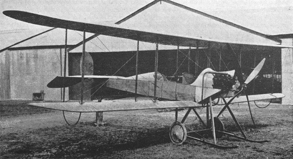
An early B.E.2 with unequal-span wings.
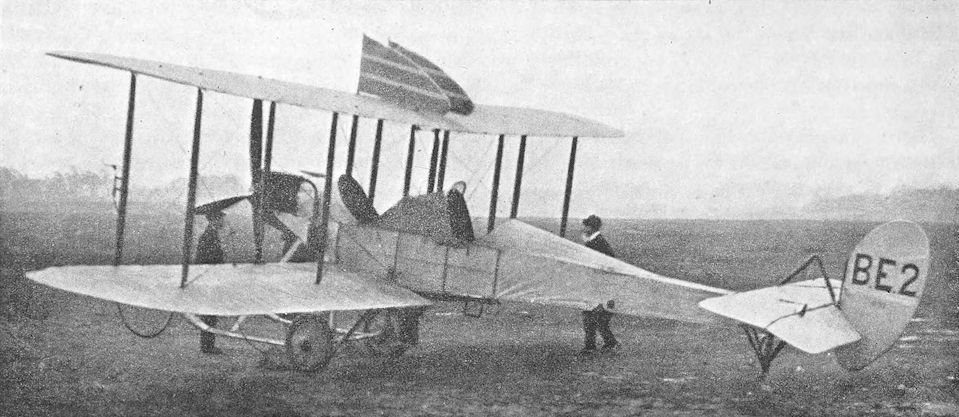
Experimental B.E.2a, serial number 601, with fin surfaces above upper wing and modified tailplane.
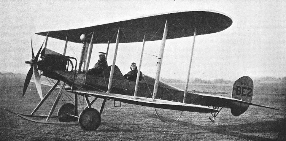
Modified B.E.2 with equal-span wings.
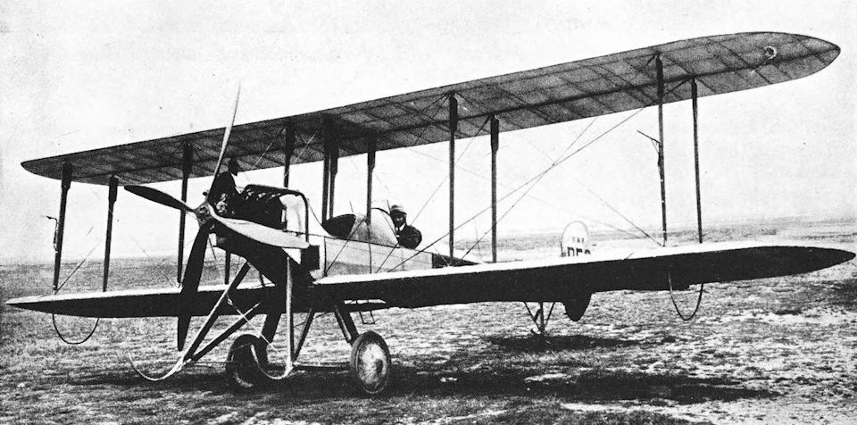
B.E.2a with modified struts and experimental oleo undercarriage.
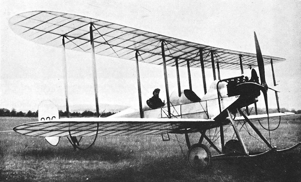
B.E.2a, serial number 226.
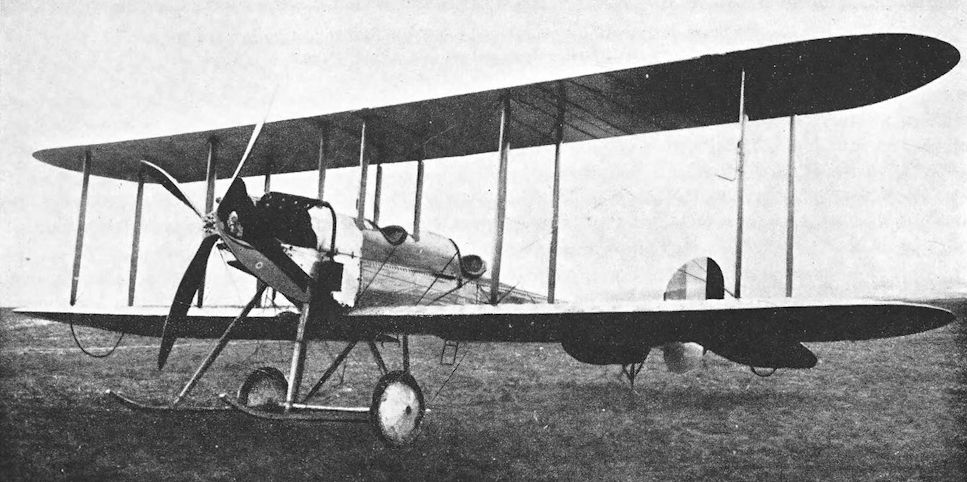
A B.E.2b, serial number 2884, showing the reduced size of the cockpit cut-outs which gave improved weather protection, and control surfaces but initially used warping for lateral control. This particular example appears to have been rigged without dihedral.
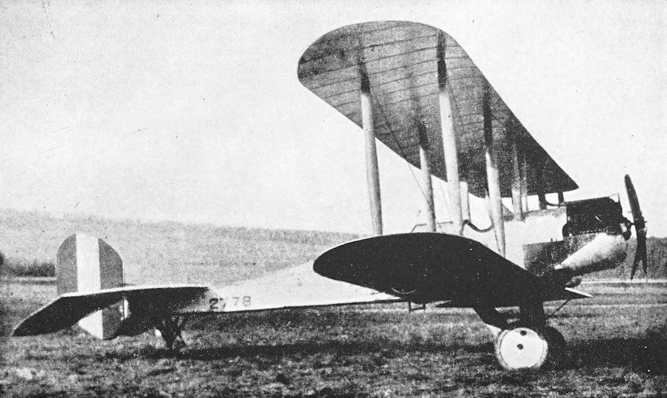
B.E.2b, serial number 2778, with vee undercarriage and cowled sump.
B.E.8 and B.E.8a
THE B.E.8 was the last of the B.E. series to have a rotary motor. The B.E.3 appeared in 1912 as a rotary-powered development of the B.E.2: it had the 50 h.p. Gnome engine. Later in the same year came the B.E.4 with the 80 h.p. Gnome; and the B.E.5, 6 and 7 all had the 140 h.p. two-row Gnome.
Construction of the first B.E.8 was begun in 1912; it was a two-seat biplane powered by the 80 h.p. Gnome. The fuselage was rather deep, and the engine was partly enclosed in a bulky “bullnose” cowling: this may have been responsible for the B.E.8’s nickname “The Bloater”. Aft of the cockpits the fuselage tapered sharply to the sternpost. The two-bay wings were of equal span and were heavily staggered; lateral control was by wing-warping.
Only three B.E.8s were built at Farnborough; production of the type was entrusted to manufacturing firms. The prototypes had no fin; there was no division between the seats; and the engine drove a two- bladed airscrew. The type was ordered into small-scale production, and contracts were let early in 1914. The production B.E.8s differed from the prototypes in detail. The most obvious modification was the addition of a fin similar to that of the B.E.2c; a short top-decking was fitted between the seats to form two separate cockpits; and a four-bladed airscrew with unusually narrow blades was fitted.
The B.E.8 was issued to the R.F.C. during the months preceding the outbreak of war. No squadron was equipped throughout with the type, and when the R.F.C. went to France the first B.E.8 to reach the Continent was the solitary specimen which was flown over by No. 3 Squadron on August 13th, 1914. This machine crashed at Amiens on August 16th; it caught fire, and its crew (Second Lieutenant E. W. C. Perry and Air Mechanic H. E. Parfitt) were killed.
Three B.E.8s were originally on the strength of the Aircraft Park which accompanied the R.F.C. to France, but one or two of them may have been used to bring squadrons up to strength. No. 5 Squadron had a few B.E.8s, but lost one within three days of arriving in France: on August 18th, the machine flown by Second Lieutenant R. R. Smith-Barry crashed at Peronne and the observer, Corporal F. Geard, was killed. Smith-Barry broke a few bones, but survived to originate the famous Gosport system of flying instruction.
When No. 6 Squadron set out for France on October 4th, 1914, its equipment included two B.E.8s; and No. 1 Squadron had four Bloaters on its strength when it went to France on March 7th, 1915. On March 12th, these four B.E.8s bombed the railway bridge at the north-east corner of Douai and the junction at Don: they were flown solo by Captain E. R. Ludlow-Hewitt and Lieutenants E. O. Grenfell, V. A. Barrington-Kennett and O. M. Moullin. The last-named officer failed to return and was later reported a prisoner-of-war.
The B.E.8 was used at training units, where it was reinforced early in 1915 by the B.E.8a. The B.E.8a was generally very similar to the B.E.8, but had new wings similar to those of the B.E.2c: double-acting ailerons replaced the warp control of the earlier machine and stagger was reduced. Whereas the tailplane of the B.E.8 was fitted above the upper longerons of the fuselage, the re-designed surface of the E.8a was mounted between the longerons as on the B.E.2C. Some B.E.8a’s later had the B.E.2e-type fin with rounded leading edge.
The standard power unit of the B.E.8a was the 80 h.p. Gnome, but one machine was fitted with the experimental 120 h.p. R.A.F. 2 nine-cylinder radial engine. The little-known R.A.F. 2 was designed at Farnborough in October, 1913, and made its first bench run early in 1914.
SPECIFICATION
Manufacturers: The Royal Aircraft Factory, Farnborough, Hants.
Other Contractors: B.E.8: The British & Colonial Aeroplane Co., Ltd., Filton, Bristol. Vickers, Ltd. (Aviation Department), Imperial Court, Basil Street, Knightsbridge, London, S.W. B.E.8a: The Coventry Ordnance Works, Ltd., Coventry.
Power: 80 h.p. Gnome. An experimental installation of the 120 h.p. R.A.F. 2 was made in a B.E.8a. Dimensions: B.E.8: Span: 39 ft 6 in. Length: 27 ft 3 in. B.E.8a: Span: 37 ft 8 1/2 in.
Performance: B.E.8: maximum speed at ground level, 70 m.p.h. Climb to 3,000 ft, 10 min 30 sec.
Armament: There was no standard installation, but the contemporary practice was for pilots and observers to carry a rifle, carbine, revolver or hand grenades. A single 100-lb bomb could be carried.
Service Use: B.E.8: Western Front: R.F.C. Squadrons Nos. 1, 3, 5 and 6. (No. 7 Squadron had one B.E.8 before the outbreak of war.) Training: various training units, including C.F.S., Upavon, and Gosport. One B.E.8 was with No. 3 Flight R.N.A.S., Westgate, in July, 1915.
Production and Allocation: The total extent of production is not known. The British & Colonial Co. built six B.E.8s, two under Contract No. A.2321 and four under Contract No. A.2366. Twenty-two B.E.8s were delivered to the R.F.C.: five went to France in 1914, five in 1915 and twelve to training units. All of the thirty-eight B.E.8a’s which were delivered went to training units, twenty-nine in 1915 and nine in 1916.
Serial Numbers: B.E.8: 423, 424, 636, 643, 656, 693, 729. B.E.8a: between and about 2134 and 2164.
Notes on Individual Machines: 424: used at C.F.S., Upavon. 636 and 656 were built by the British & Colonial Aeroplane Co., Ltd. 643: R.N.A.S., Westgate.

RAF BE.8 developed from the BE.3/4. The prototype originally had an undivided cockpit and no fin.

A production standard B.E.8, built at Farnborough, with a triangular fin, divided cockpits, and an 80hp Gnome engine.
CENTRAL FLYING SCHOOL, UPAVON, 1914. - A B.E. 8 of A Flight, with air-mechanics in attendance, tuning up before a cross-country flight.
CENTRAL FLYING SCHOOL, UPAVON, 1914. - A B.E. 8 of A Flight, with air-mechanics in attendance, tuning up before a cross-country flight.

B.E.8a with original small fin, serial number 2134 seen at Farnborough. This was a Vickers-built aircraft and after a short period with the Wireless Trials Unit it was allocated to 9 Squadron, which undertook much of this development work. The use of wireless telegraphy was seen as essential, especially for the co-ordination of artillery shoots. The BE8a was often referred to as the Bloater' and it saw little operational service.

B.E.8a with experimental skis attached to the undercarriage.
The later S.E. aeroplanes were descended from a remarkably clean single-seat tractor biplane built in 1912 and designated B.S.1, or Bleriot Scout. It was the first aeroplane in the world which was built as a single-seat high-speed scout. The B.S.1 crashed in March, 1913, after having been timed at a speed of 91-4 m.p.h. over a measured course. It was rebuilt with a completely new tail-unit, and was fitted with an 80 h.p. Gnome engine in place of the 100 h.p. two-row Gnome which was originally fitted.
THE F.E.3 was a remarkable single-engined pusher biplane which was built in 1913. It had only a single tail-boom which passed through the hollow airscrew shaft, and was powered by the 100 h.p. Chenu engine. The type did not go into production, and saw no war service. In the summer of 1913 it was used as a static test-bed for experiments in the firing of a one-pounder gun made by the Coventry Ordnance Works. These significant tests showed that the firing of a gun from an aeroplane would be unlikely to have any detrimental effect upon the aircraft’s stability in flight.
The F.E.6 was built in 1914; it was a two-seat pusher built on similar lines to the F.E.3 with a single tail-boom through the hollow airscrew shaft, and its engine was a 120 h.p. Austro-Daimler.
The F.E.6 was built in 1914; it was a two-seat pusher built on similar lines to the F.E.3 with a single tail-boom through the hollow airscrew shaft, and its engine was a 120 h.p. Austro-Daimler.
R.E.1
BEFORE the outbreak of war, it was generally believed that if aeroplanes were to play any part in warfare it would be that of reconnaissance: the conception of aerial combat between opposing aircraft existed only in the more Wellsian imaginations of the time.
For reconnaissance purposes, it was argued, an aeroplane ought to be as stable as possible. If a pilot needed to pay little attention to the flying of his aeroplane he would obviously be able to concentrate on his observations and the writing of his report. This was the philosophy of the time, and in 1912 the Royal Aircraft Factory set about the designing of an aeroplane for reconnaissance duties. The result was the first Reconnaissance Experimental, or R.E.1, which appeared early in 1913.
As has been told in the history of the B.E.2c, E. T. Busk took up an appointment at Farnborough on June 10th, 1912. He had been interested in the problems of aeroplane stability, which had been theoretically investigated by Mr (later Dr) F. W. Lanchester and by Professor G. H. Bryan. At the National Physical Laboratory, Leonard Bairstow had done a good deal of practical work based on Professor Bryan’s investigations, and he and Busk collaborated in applying all the available data to the problem of making the R.E.1 inherently stable.
Two R.E.1s were built in 1913, and were of interest from the structural standpoint because the fuselages were constructed of steel tubing at a time when wood was the almost universal material.
Both R.E.1s were two-seat tractor biplanes with single-bay wings, but they differed in appearance. The first, No. 607, was distinctly the better-looking of the two. As originally built, the machine had pronounced stagger on the mainplanes, and lateral control was by wing-warping. The tailplane was somewhat similar to that of the B.E.2 and was mounted on top of the upper longerons; a fin was incorporated in the tail-unit at an early stage.
The 70 h.p. Renault engine was installed without a cowling, and the exhaust pipes were led forward round the front of the engine and then downwards and rearwards. The undercarriage was a twin-skid structure generally similar to that of the B.E.2.
Later in its career, No. 607 was given a new set of mainplanes which had ailerons for lateral control; the stagger was also reduced. At the same time the tail-unit was modified by reducing the area of the fin and fitting a larger rudder; a new tailplane of rectangular plan-form was fitted between the longerons.
It seems that Busk did most of his work on the other R.E.1, No. 608. This machine had a longer fuselage than No. 607 and had no fin: there was a large, ugly, balanced rudder. At one time, four fin surfaces were fitted above the upper wing of this R.E.1; one was mounted directly over each pair of interplane or centre-section struts.
Busk made exhaustive tests in the R.E.1. He flew it in all weathers in order to prove the soundness of the theories underlying its design, and took considerable risks in doing so. Having proved theoretically, with the aid of models, that the R.E.1 would automatically right itself from a dive, he climbed to a great height in the aircraft, put it into a dive and released the controls. As he had predicted, the machine recovered without assistance from him. The R.E.1 was so stable that it would bank automatically when rudder was applied, and automatically assumed the correct gliding angle when the throttle was closed.
This state of automatic stability had been achieved by November, 1913, by which time Busk had made flights of several hours’ duration and in winds up to 38 m.p.h. without touching the controls, save for landing. On May 19th, 1914, he flew the R.E.1 before King George V on the occasion of the Royal visit to Farnborough: on that flight he took Major Clive Wigram as his passenger.
It has been stated that one of the R.E.1s was fitted with a twin-float undercarriage and flown as a seaplane from Fleet and Frensham Ponds by Geoffrey de Havilland: the seaplane version was designated H.R.E. This reference may, however, have been a confusion with the H.R.E.2.
Shortly after the R.F.C. went to France to join the British Expeditionary Force in the field, a request was sent on August 22nd, 1914, for any spare aeroplanes to be sent to reinforce the squadrons. One of the five machines that were sent in response was an R.E.1. It was given to No. 2 Squadron.
SPECIFICATION
Manufacturers: The Royal Aircraft Factory, Farnborough, Hants.
Power: 70 h.p. Renault.
Performance: Maximum speed: 78 m.p.h.; stalling speed: 48 m.p.h. Initial rate of climb: 600 ft/min.
Service Use: Western Front: No. 2 Squadron, R.F.C.
Production: Two R.E.1s were built in 1913.
Serial Numbers: 607-608.

The first R.E.1, serial number 607, in its original form with warping wings.
Only two of these machines were built in 1913.
Only two of these machines were built in 1913.

R.E.1. No. 607, modified to have ailerons and smaller fin and rudder.

The second R.E.1, serial number 608, with Edward Busk in the cockpit. Note the four fin surfaces above the upper wing and the balanced rudder.
H.R.E.2
IN 1913 the Royal Aircraft Factory, working to the specification of the Air Department of the Admiralty, designed a two-seat seaplane for the Naval Wing of the R.F.C. At first the aircraft was referred to as the Naval Hydro aeroplane: its official designation was H.R.E.2, or Hydro Reconnaissance Experimental, and despite its Naval connexion it was numbered in the R.E. series.
It first appeared as a landplane with the usual wheeled twin-skid undercarriage, and had a 70 h.p. Renault vee-eight engine. It was a two-seat tractor biplane with two-bay wings; the wings were slightly staggered and wing-warping was used for lateral control. The one-piece tailplane was mounted on top of the upper longerons, and there was a one-piece elevator. The oval rudder was reminiscent of that of the B.E.3: it was mounted wholly above the tailplane with its major axis raked backwards at about 45 degrees and with part of its surface forward of the pivot to provide a balance area. In this form the H.R.E.2 was tested on July 1st, 1913.
The float undercarriage was then substituted for the wheels. There were two main floats, with vertical bows and flat tops, tapering to a flat pointed after-body; and a small tail-float was fitted. The tests of the original landplane probably indicated that the machine would be underpowered and unstable as a floatplane, for the power was increased by fitting the 100 h.p. Renault vee-twelve engine, and the vertical tail area was increased to compensate for the side area of the floats. A simple triangular fin was fitted, and to it was attached an ear-shaped rudder. These surfaces were mounted wholly above the tailplane; the rudder was appreciably taller than the fin, and the combination of the two was hideous. The rudder was directly connected to a small water-rudder at the rear of the tail-float. The coaming at the front of the rear cockpit was extended slightly in order to be closer about the pilot, whose seat that was: doubtless the intention was to keep spray out of the cockpit.
The H.R.E.2 in its seaplane form was tested on Fleet Pond. Taxying trials were made with and without a passenger, but when a flight was attempted the H.R.E.2 failed to rise: it struck the land, wiped off its undercarriage, and overturned.
The machine was badly damaged in this crash, but it was rebuilt as a landplane. It retained the 100 h.p. Renault and modified tail unit. Ultimately, new wings were fitted on which ailerons replaced the original warp control, and the shape of the rear cockpit was again modified.
The H.R.E.2 was still on the strength of the R.N.A.S. when war broke out, and presumably flew for at least a short period during the war.
SPECIFICATION
Manufacturers: The Royal Aircraft Factory, Farnborough, Hants.
Power: 70 h.p. Renault; 100 h.p. Renault.
Dimensions: Span: 45 ft 3 1/2 in. Length: 32 ft 3 in. Height: 12 ft 2 in. Chord: 6 ft. Gap: 6 ft 3 1/2 in. Stagger: 1 ft 7 in. Dihedral: 2°. Incidence: 4° 30'. Span of tail: 11 ft 7 in. Distance between float centres: 7 ft 3 in. Airscrew diameter: 9 ft 6 in.
Production: One H.R.E.2 was built in 1913.
Serial Number: 17.

The H.R.E.2 No.17 in its original landplane form with 70 h.p. Renault engine and B.E.3-type balanced rudder.

The H.R.E.2 on Fleet Pond as a seaplane, with 100 h.p. Renault engine and modified vertical tail assembly.

The H.R.E.2 rebuilt as a landplane.

H.R.E.2. The aircraft in its final form with ailerons in place of wing-warping.
S.E.2a
THE S.E. series began nominally with a peculiar canard biplane which appeared in 1911. It was named Santos Experimental No. 1, or S.E.1, after Santos Dumont; for the great Brazilian pioneer was regarded as the originator of the tail-first arrangement. The S.E.1 crashed on August 18th, 1911.
The later S.E. aeroplanes were descended from a remarkably clean single-seat tractor biplane built in 1912 and designated B.S.1, or Bleriot Scout. It was the first aeroplane in the world which was built as a single-seat high-speed scout. The B.S.1 crashed in March, 1913, after having been timed at a speed of 91-4 m.p.h. over a measured course. It was rebuilt with a completely new tail-unit, and was fitted with an 80 h.p. Gnome engine in place of the 100 h.p. two-row Gnome which was originally fitted.
The rebuilt machine was renamed B.S.2, but the designation was soon changed to S.E.2. Now, however, the initials S.E. signified Scout Experimental. A further reconstruction in 1913 produced the S.E.2a.
Like its predecessors, the S.E.2a was a clean single-seat biplane with single-bay staggered wings. The 80 h.p. Gnome had a cowling of good aerodynamic form, and a spinner was fitted to the airscrew. The fuselage was of circular cross-section: aft of the cockpit the covering was of fabric over a built-up structure of longerons and spacers, whereas the fuselages of the B.S.1 and S.E.2 had been wooden monocoques. The tail-unit was again modified, and the area of the fin and rudder was greatly increased. Lateral control was by wing warping, but auxiliary mid-bay flying wires were fitted to the upper mainplanes. The S.E.2a was one of the first aeroplanes to have streamlined Rafwires instead of cables for the interplane bracing. The undercarriage was a normal twin-skid structure.
In January, 1914, the S.E.2a was taken on the strength of No. 5 Squadron, R.F.C. Apparently it was not flown very much by that unit, for in the spring of 1914 it stood in one of No. 3 Squadron’s hangars at Netheravon until Major J. F. A. Higgins flew it to Farnborough. The S.E.2a did not go to France when war broke out, but in October, 1914, it was sent to join No. 3 Squadron at Moyenneville.
The S.E.2a’s active service lasted until March, 1915. When it first went to France its performance was better than most of its contemporaries, and of it was said: “Its speed enabled it to circle round the enemy’s machines and gave it a decided ascendancy.” Among the pilots who flew the S.E.2a in France was Lieutenant A. R. Shekleton. The armament appears to have varied from one .45 Service revolver to two rifles, mounted on either side of the fuselage and firing outwards to clear the airscrew.
SPECIFICATION
Manufacturers: The Royal Aircraft Factory, Farnborough, Hants.
Power: 80 h.p. Gnome.
Dimensions: Span: 27 ft 6 in.
Weights: Loaded: 1,200 lb.
Performance: Maximum speed at ground level: 96 m.p.h.
Armament: Two rifles, one mounted on either side of the fuselage, pointing outwards to miss the airscrew; or one .45-in. Service revolver.
Service Use: Pre-war: No. 5 Squadron, R.F.C. Western Front: No. 3 Squadron, R.F.C.
Production: One S.E.2a was built in 1913.
Serial Number: 609.

RAF SE.2a was transferred to the RFC in January 1914 and served in France armed with two rifles until March 1915.
B.E.2c, 2d and 2e
EDWARD TESHMAKER BUSK left King’s College, Cambridge, in 1908. He took the Mechanical Sciences Tripos in 1907, and spent a further year at Cambridge in research. From 1909 until mid-1911 he worked with Halls and Co. of Dartford, and in 1911 he began to develop his interest in aviation.
At that early date he was interested in the problem of inherent stability in aeroplanes, and made some investigations into the nature and causes of wind gusts. Early in 1912, he began to learn to fly at Hendon at the flying school of the Aeronautical Syndicate, Ltd., but did not take his Royal Aero Club certificate.
In June, 1912, Professor Hopkinson of King’s College recommended Busk to Mervyn O’Gorman, the Superintendent of the Royal Aircraft Factory, for the post of Assistant Engineer Physicist, and Busk took up his appointment on June 10th, 1912.
His work at Farnborough consisted chiefly of research in aircraft stability and control design. He realised that, in order to carry out his experiments thoroughly, he must complete his flying training: this he did under the tuition of Geoffrey de Havilland, and by the summer of 1913 was sufficiently skilled as a pilot to be able to begin a series of experiments in stability.
Busk began his investigations with the B.E.2a. He approached his task with perseverance and great courage, for, in establishing the exact degree of instability of the B.E.2a, he flew the machine beyond the limits of its controllability on several occasions. His findings provided data for the design of the R.E.t, which emerged in November, 1913, as the first R.A.F. inherently stable aeroplane, and for a development of the basic B.E.2 design.
The latter machine was designated B.E.2C, and was flying in June, 1914. The prototype had the fuselage, undercarriage and engine installation of the B.E.2b, but new mainplanes with a marked degree of stagger were fitted. Double-acting ailerons replaced the warp control of the earlier B.Es; a fixed fin was added to the tail unit; and a new tailplane was mounted between the upper and lower longerons, braced to the fin by steel-tube struts. The fuselage was a typical wire-braced box girder, made in two parts which were joined just behind the rear cockpit. The wings had wooden spars, ribs and riblets and, in the earlier B.E.2c’s, the external bracing was by cables. The fin and rudder were made of steel tube. The covering was of fabric throughout, apart from the metal engine cowling and the plywood decking about the cockpits.
In June, 1914, Major (later Air Vice Marshal Sir) Sefton Brancker flew the prototype B.E.2C from Farnborough to Netheravon. He climbed to 2,000 feet over Farnborough and thereafter did not touch the controls again until he was at 20 feet on the approach to Netheravon. During his flight he wrote a reconnaissance report of the country over which he flew.
As the summer of 1914 wore on, it became obvious that war was imminent. Aeroplanes were ordered in haste, and it was decided to order the B.E.2C in quantity, since it promised to be superior to the earlier B.E.2 variants in construction and performance. This led to delay, for complete sets of drawings were not immediately available; moreover, some of the contractors for the type had never before built aircraft.
It would be hard to condemn the decision to order what was at that time large-scale production of the B.E.2c: in fact, it was an act of faith and considerable courage. The aircraft had not been fully tested, but it had already shown itself to be an excellent flying machine with remarkable stability, a quality which promised well for its employment as a reconnaissance machine. At that time, aerial combat had not been thought of, save by a few visionaries; and no-one foresaw that the B.E.’s great stability would put it at a serious disadvantage in aerial fighting.
The B.E.2c was not, for its day, particularly simple in its construction, and successive modifications were a sore trial to the first contractors for the type. Among the firms who undertook its manufacture were Messrs G. and J. Weir, Ltd., of Glasgow, and the Daimler Co., Ltd., of Coventry. Contracts were also placed with Sir W. G. Armstrong, Whitworth & Co., Ltd., but after study of the drawings that firm represented that the B.E.2C was unnecessarily complicated. They therefore sought and (what is more remarkable) obtained permission to build an aeroplane which would be simpler but equally efficient. The result was the Armstrong Whitworth F.K.3.
A single B.E.2C was taken to France by the Aircraft Park, which arrived at Boulogne on August 18th, 1914. Production machines began to appear late in 1914, but by March 10th, 1915, the seven squadrons in the field could muster a total of only thirteen B.E.2c’s between them. The first unit to go to France equipped throughout with the type was No. 8 Squadron, R.F.C., which arrived on April 15th, 1915.
The early production B.E.2c’s were very similar to the prototype. They retained the Renault engine and skid undercarriage, but some had a slight refinement in the shape of a cowling over the engine sump. In each outer bay of the wings an auxiliary mid-bay flying-wire was added to the upper front spars. The arrangement of the control cables for the tail surfaces was improved.
The Renault engine which powered the B.E.2c had provided the basis for original design work undertaken at the Factory with the object of producing a satisfactory British power-unit with a reasonable power/weight ratio. This work began in January, 1913, and culminated in the following year in the appearance of the R.A.F. 1 engine of 90 h.p. Like the B.E.2C, the R.A.F. 1 was not fully tested at the outbreak of war, nor were full sets of drawings available, yet it was ordered in quantity from various contractors. The first R.A.F. 1 was installed in a B.E.2c, but development was delayed by the loss of the engine on November 5th, 1914, when the aircraft in which it was being flown burst into flames at 800 feet above Laffans Plain and crashed. But the crash caused a far greater loss to British aeronautical science than the mere destruction of an engine which could, sooner or later, be replaced: Busk was the pilot of the B.E.2c; and he lost his life.
The production version of the R.A.F. 1 engine was known as the R.A.F. 1a. Deliveries began in the spring of 1915, and the engine became the standard power unit of the B.E.2C. The exhaust pipes varied considerably in length and configuration, but the twin upright stacks running up in front of the centresection were perhaps the best-known arrangement. Many of the B.E.2c’s built for the R.N.A.S. had long pipes running along the fuselage and terminating just abaft the pilot’s cockpit.
At about the same time as the introduction of the R.A.F. 1a engine, the B.E.2c’s undercarriage was modified to consist of two simple vees: each vee was made of steel tube with wooden fairings, and there were two steel-tube spreader bars between which the axle lay. Springing was provided by the 44 feet of 3/8-inch rubber shock cord which bound the axle to each vee strut. Some B.E.2c’s were built with an oleo undercarriage similar to that of the F.E.2b and R.E.7, and a few of these machines went to France. The Daimler Company produced some of the oleo-fitted B.E.2c’s.
Other modifications were introduced as time went on. The tailplane, which was originally made in one piece, was later built in two parts; concurrently, the steel-tube struts bracing the tailplane were replaced by Rafwires.
Rafwires also replaced the cables which had braced the mainplanes of all early B.E.2c’s. The mainplanes themselves were changed: the early machines had had wings of R.A.F.6 section at an angle of incidence of 3 30', but these were changed for surfaces of R.A.F.14 section at 4 09'.
For some months the B.E.2C gave good service as a reconnaissance aircraft, and made occasional bombing attacks. One of the earliest exploits of the latter kind was the daring attack on the enemy airship sheds at Gontrode, made by Lieutenant L. G. Hawker on April 19th, 1915. His B.E.2C carried three bombs.
But in the late summer of 1915, the rather experimental attempts at aerial combat which had occurred up to that time were suddenly superseded by a new fighting technique in which the advantage at first lay wholly with the enemy. The Fokker monoplane was the vehicle which first brought a new weapon into operational use. Armed with a machine-gun which, thanks to a mechanical interrupter gear, could be fired straight ahead through the revolving airscrew, the Fokker spelt doom to many Allied aircraft and particularly B.Es.
In combat, the B.E.2c proved to be nearly helpless. There were several reasons why this was so. Its stability was such that it could not be manoeuvred rapidly; and even if it had been tractable it could not have been provided with effective armament. No British interrupter gear was available at the time, and the observer’s position in the front cockpit, directly under the centre-section, was a severe obstacle to the fitting of any kind of defensive armament.
A remarkable variety of gun-mountings were fitted to B.E.2c’s. Most of them were devised by their crews, but all had one thing in common: they were of little practical use and generally reduced the B.E.’s mediocre performance to a dangerously low level. The observer was usually the gunner, and he had to move his Lewis gun bodily from one mounting to another around his cockpit; but from all save the rearmost his field of fire was hedged about by wings, wires and struts. One of the best arrangements of a Lewis gun fired by the pilot was that devised by Captain L. A. Strange of No. 12 Squadron. The gun was mounted on the side of the fuselage and pointed outwards to clear the airscrew: the pilot had therefore to fly crabwise when he wanted to fire.
The desperation of B.E. crews found expression in a weapon invented by an officer of No. 6 Squadron. From a small winch in the cockpit he lowered a lead weight on a steel cable; this he attempted to entangle in the airscrew of an enemy aircraft by manoeuvring above it. Needless to say, the device was unsuccessful.
From October, 1915, onwards, throughout the months preceding the Battle of the Somme, the history of the war in the air contains a dreary recital of mounting losses, including many B.E.2c’s, inflicted by the Fokker monoplane. Evidence of the Fokker’s effectiveness and the B.E.2c’s defencelessness is provided by the size of the escort which was detailed to accompany a B.E. of No. 12 Squadron on a reconnaissance flight on February 7th, 1916. The flight was not carried out, but the escort was to have consisted of three other B.E.1c’s, four F.E.2b’s, four R.E.7s and one Bristol Scout - twelve machines in all.
In addition to its reconnaissance and artillery-spotting activities, the B.E.2c acted as a bomber on many occasions. Captain Strange, then of No. 6 Squadron, had shown what could be done by his attack on Courtrai station on March 10th, 1915: his B.E.2C was armed with only three 25-lb bombs, but he did sufficient damage to delay rail traffic for three days.
Bombing raids became more frequent as more aircraft became available. The R.F.C.’s first night raid was made by two B.E.2c’s of No. 4 Squadron on the night of February 19th/20th, 1916; the aircraft were flown by Captains E. D. Horsfall and J. E. Tennant. Their objective was Cambrai aerodrome, where Tennant dropped his seven 20-lb Hales bombs on the sheds from 30 feet. Horsfall’s two 112-pounders failed to leave the racks over the target, and did not drop until the B.E. was nearly home again.
On these raids, as on all bombing missions, the B.E.2C was flown without an observer, for it could not lift both bombs and an observer together. Defensive armament was also reduced to a minimum: the pilot usually had nothing more effective than a rifle or carbine. Bombing attacks on enemy railways were carried out by twenty-eight B.E.2c’s during the preparations for the Battle of the Somme, and on July 1st, 1916, the day of the great offensive itself, a similar number made further attacks. On July 28th, the B.E.2c’s of Nos. 8 and 12 Squadrons dropped fifty-seven 112-lb bombs on the railway junction north of Aubigny-au-Bac.
After one or two British aeroplanes had been brought down by rifle and machine-gun fire from the ground the R.F.C. asked for armoured aeroplanes. Some B.E.2c’s were provided with armour about and below the cockpits and engine; but its weight (which was no less than 445 lb) and the total absence of streamlining had a detrimental effect upon the machine’s performance. One of these armoured B.E.2c’s was used by No. 15 Squadron, and was flown on ground-strafing duties by Captain Jenkins of that unit during the Battle of the Somme. In three months it was fitted with no fewer than eighty new wings and many other components.
The B.E.2C was also built in substantial numbers for the R.N.A.S., and that Service was the first to use the type outside France. Two Renault-powered B.E.2c’s reached Tenedos early in April, 1915, to form part of the equipment of No. 3 Wing, R.N.A.S., during the Dardanelles campaign. No. 2 Wing brought six more Renault-powered machines in August.
Many of the B.E.2c’s built with the R.A.F. la engine for the R.N.A.S. had a small bomb-rack directly under the engine; it could carry three bombs. Some of the R.N.A.S. bomber B.E.2c’s had the front cockpit faired over.
On April 3rd, 1915, two B.E.2c’s, numbered 968 and 969, left England for South-West Africa. They had been built for the Admiralty but were transferred to the South African Aviation Corps. They arrived at Walvis Bay on April 30th, but were damaged in trial flights and took no part in the South-West African campaign.
When that campaign was over, some of the officers and men who had taken part in it provided the nucleus of No. 26 Squadron, which arrived at Mombasa with eight B.E.2c’s on January 31st, 1916, for service in German East Africa. The airscrews had not been packed with the machines at Farnborough, so the squadron had to make do with only five spare airscrews, none of which was of the correct type. The B.Es of this squadron did a great deal of excellent work under appalling conditions. On January 30th, 1917, No. 26 Squadron took over three R.A.F.-powered B.E.2c’s of R.N.A.S. type from No. 7 (Naval) Squadron, which had been withdrawn by the Admiralty. It was on one of them, No. 8424, that Captain G. W. Hodgkinson and Lieutenant L. Walmsley made many long-range reconnaissances; the observer carried extra tins of petrol in his cockpit and from them he replenished the tank while in flight.
In the near East, B.E.2c’s flew and fought with Squadrons Nos. 14 and 17 in Egypt; with Nos. 14 and 67 (Australian) Squadrons in Palestine; with No. 30 Squadron in Mesopotamia, where the B.Es helped to drop food to the beleaguered garrison of Kut-al-Imara; and with No. 17 Squadron in Macedonia, whence that unit went from Egypt in July, 1916. One of No. 30 Squadron’s B.E.2c’s was flown as a single-seat fighting scout: with twenty-five gallons of fuel it had a speed of 88 m.p.h. at 2,000 feet, and climbed to 10,000 feet in twenty-two minutes.
In India the B.E.2c was flown by No. 31 Squadron and later by No. 114 Squadron also. There it played a part in quelling the unruly tribes of the North-West Frontier.
The B.E.2C is seldom credited with successes of any kind, but it did perform well on Home Defence duties as an anti-Zeppelin aircraft. Until the enemy began to use the Gotha biplanes in place of his airships, the B.E.2C was the standard British Home Defence aeroplane. In this particular kind of work the machine’s stability was a real asset, for it simplified night-flying and made the aircraft a steady gun platform.
Five enemy airships fell to the guns of B.E.2c’s: the Schutte-Lanz S.L.11 and the Zeppelins L.32, L.31, L.34 and L.21. The wooden-framed Schutte-Lanz airship was shot down on September 3rd, 1916, by Lieutenant W. Leefe-Robinson of No. 39 Squadron, who received the Victoria Cross for this action. Exactly three weeks later, on September 24th, Second Lieutenant F. Sowrey, also of No. 39 Squadron, shot down the Zeppelin L.32 over Billericay; he was flying a Bristol-built B.E.2C, No. 4112.
The British and Colonial Aeroplane Co. built ten specially modified B.E.2c’s, numbered 4700-4709, for Home Defence duties. These were single-seaters, and the space normally occupied by the front seat contained an extra petrol tank to increase endurance for anti-Zeppelin work.
The Home Defence B.Es were armed in a variety of ways. Some carried canisters of Ranken darts, some relied on bombs, but the majority were armed with a Lewis gun firing incendiary ammunition. Experiments were also carried out with Le Prieur rockets: a B.E.2C which had an installation for ten rockets was No. 8407. At Farnborough tests were made with a B.E.2C which had two grapnels attached to cables. These were normally carried under the fuselage and may have been intended to be anti-airship weapons.
In 1915, a slightly modified version of the design, known as the B.E.2d, appeared. This variant had dual controls and a revised fuel system: there was an external gravity petrol tank under the port upper mainplane, an addition which provided the chief external distinguishing feature of the type. The sides of the forward cockpit were rather lower than on the B.E.2C. The B.E.2d began to come into service in the spring of 1916, but was no improvement on the B.E.2C.
<...>
The standard engine for the B.E.2c, 2d and 2e was the 90 h.p. R.A.F.1a, but several other types of engine were installed in some machines. The 105 h.p. R.A.F.1b became available in 1916 and was fitted to some B.Es; this engine had cylinders of larger bore. A few machines were fitted with the later R.A.F.1d, which had aluminium cylinders with deep fins and overhead inlet and exhaust valves. (The R.A.F.1a and 1b had cast-iron cylinders with side inlet valve and overhead exhaust valve. The R.A.F.1d was of considerable historical importance in view of the use of aluminium for its cylinders; it owed its existence to the experimental work of H. P. Boot and G. S. Wilkinson with aluminium cylinders at Farnborough.)
Some B.E.2c’s originally built for the R.F.C. were handed over to the R.N.A.S. without engines, and several were fitted with the 90 h.p. Curtiss OX-5. One of the contractors responsible for fitting the Curtiss engine was the firm of Frederick Sage & Co., Ltd. A few of the B.E.2e’s which were handed over to the R.N.A.S. for training purposes were fitted with the 75 h.p. Rolls-Royce Hawk engine.
The 150 h.p. Hispano-Suiza was fitted to several B.E.2c’s and 2e’s. One of the first installations in a B.E.2c was made unofficially at No. 1 Aircraft Depot at St. Omer early in 1916. At Farnborough, the Hispano was first fitted to the B.E.2c No. 2599; this machine had its radiators disposed in a peculiar manner along each cylinder block.
A more conventional radiator installation for the Hispano-Suiza was made by the Belgians when they modified several of their B.E.2c’s to have the 150 h.p. engine: a flat circular radiator was fitted in the nose. In an attempt further to improve their B.E.ac’s, the Belgians modified the control system and placed the pilot in the front cockpit. He was then provided with a synchronised Vickers gun, and a Nieuport-type ring-mounting was fitted over the rear cockpit for the observer’s Lewis gun. Unfortunately, the additional weight of the greatly improved armament had an adverse effect upon the aircraft’s performance, for its service ceiling was only 11,000 feet. The modifications were made under the direction of Lieutenant Armand Glibert of the 6th Belgian Squadron, but he was one of the first to lose his life on a Hispano-B.E. While on a reconnaissance flight far inside the German lines he and his observer, Lieutenant Callant, were attacked by enemy fighters. Unable to climb or manoeuvre adequately, their B.E.ac was shot down and both were killed.
Some of the R.F.C.’s B.E.2e’s were fitted with the 150 h.p. Hispano-Suiza, but were used only for training purposes.
The B.E.2c and 2e were used in many experiments throughout the war. One of the most startling was begun at Kingsnorth airship station in the summer of 1915. At that time much thought was devoted to the design of an anti-Zeppelin aircraft which, as one of its most desirable qualities, would have a very long flight endurance. Commander N. F. Usborne and Lieutenant-Commander de Courcy W. P. Ireland designed a remarkable composite aircraft which consisted of an S.S.-type airship envelope to which was attached a complete B.E.2C aeroplane. It was argued that the gas bag would keep the aeroplane aloft until a Zeppelin was sighted: by means of quick-release catches the airship envelope would be cast off, and the B.E.2C would attack in the normal way. The first tests of the Airship-plane, as it was called, were made by Flight Commander W. C. Hicks in August, 1915, but the controlling gear was not satisfactory. After modifications had been made, the first trial flight was made by Usborne and Ireland. It ended tragically. At about 4,000 feet the B.E. was seen to separate prematurely from the gas bag: some of the flight controls must have been damaged, for the machine turned over as it fell away, and Lieutenant-Commander Ireland was thrown out. The B.E. crashed out of control in the goods yard of Strood railway station, and Commander Usborne was killed.
In August, 1916, a B.E.2c was used to test the first installation of the Constantinesco synchronising gear for machine-guns. This was probably the B.E.2c’s greatest service to the R.F.C. and R.N.A.S., for the Constantinesco gear was a great improvement over existing types of interrupter or synchronising gear.
An equally great service to aviation in general was rendered by the B.E.2e in which Dr F. A. Lindemann (later Lord Cherwell) carried out his very gallant experiments to investigate the phenomenon of spinning, which was not then understood.
The spinning experiments were conducted at Farnborough, as were many others in which B.Es were fitted with various airscrews, engines, instruments and wings of different aerofoil sections. Wings of R.A.F. 14, 15, 17 and 18 section were tested, and one of the B.E.2e’s which were used was fitted with wings of 6 feet 1 inch chord.
Early in 1918, B.E.2c No. 4122 was fitted with the first R.A.F. variable-pitch airscrew. Operation of the airscrew was purely mechanical and the pilot’s control consisted of a handwheel. Each of the four blades of the airscrew was built up of walnut laminations and was fitted to a steel shank. The hub was a clumsy structure, and the complete airscrew weighed 85 lb: it was 50 lb heavier than the standard walnut airscrew. The total range of angular movement of the blades was 1 o degrees.
Some of the earliest British experiments with superchargers were conducted on B.Es. In these aircraft the engine was the R.A.F.1a, and the blower was fitted directly under the fuel tank. When the blower seized (as it frequently did), the resulting shower of sparks so near the petrol tank was somewhat disquieting for the observer.
The B.E.2C continued on active service until the last year of the war: in 1918, some were still working as anti-submarine patrol aircraft. The great majority of B.Es ended their days at various training units, however. In August, 1918, twelve B.E.2e’s were sold to the Americans, and were used as trainers in England.
Thus these unwilling warriors - for the B.E.2C was originally designed to be merely a stable aeroplane, not a fighting aircraft - ended their days in comparative peace. But they achieved a kind of immortality, for they were regarded as the embodiment of the Government-designed aeroplane, mass-produced by official order, yet inefficient, ineffective and inferior for all military purposes. To blame the B.Es themselves would be to misjudge them, for they were safe and reliable flying machines, lacking only the performance and manoeuvrability necessary to survive the ever-increasing intensity of aerial warfare. The fault lay with those who continued to order the B.Es and, worse still, to send them to war long after they were obsolete.
They were the Fokker Fodder of 1915-16; they were the prey of Albatros, Halberstadt, Roland and Pfalz in 1916-17; they were the reason for Noel Pemberton-Billing’s dramatic charges of criminal negligence against the Administration and higher Command of the R.F.C. In a speech in the House of Commons on March 21st, 1916, Pemberton-Billing said: “I would suggest that’quite a number of our gallant officers in the Royal Flying Corps have been rather murdered than killed.” The Judicial Committee which was set up to investigate these charges was unable to find any foundation in fact for them.
But the stigma remained and survives to this day, redeemed only by its implied, unrecorded quantum of courage - the courage of those who flew the B.Es to war.
SPECIFICATION
Contractors; Sir W. G. Armstrong, Whitworth & Co., Ltd., Gosforth, Newcastle-on-Tyne; The Austin Motor Co. (1914), Ltd., Northfield, Birmingham; Barclay, Curie & Co., Ltd., Whiteinch, Glasgow; William Beardmore & Co., Ltd., Dalmuir, Dumbartonshire; The Blackburn Aeroplane & Motor Co., Ltd., Olympia, Leeds; The British Caudron Co., Ltd., Broadway, Cricklewood, London, N.W.a; The British and Colonial Aeroplane Co., Ltd., Filton, Bristol; The Coventry Ordnance Works, Ltd., Coventry; The Daimler Co., Ltd., Coventry; William Denny & Bros., Dumbarton; The Eastbourne Aviation Co., Ltd., Eastbourne; The Grahame-White Aviation Co., Ltd., Hendon, London, N.W.; Handley Page, Ltd., 110 Cricklewood Lane, London, N.W.; Hewlett & Blondeau, Ltd., Clapham, London; Martinsyde, Ltd., Brooklands, Byfleet; Napier & Miller, Ltd., Old Kilpatrick; Ruston, Proctor & Co., Ltd., Lincoln; The Siddeley-Deasy Motor Car Co., Ltd., Park Side, Coventry; Vickers, Ltd. (Aviation Department), Imperial Court, Basil Street, Knightsbridge, London, S.W.; The Vulcan Motor & Engineering Co. (1906), Ltd., Crossens, Southport; G. & J. Weir, Ltd., Cathcart, Glasgow; Wolseley Motors, Ltd., Adderley Park, Birmingham. Australia: a few B.E.2c’s were built at the Australian Flying School, Point Cook.
Dimensions:
Aircraft B.E.2c B.E.2d B.E.2e Experimental B.E.2e with R.A.F. 18 wings
Span, upper 37 ft 36 ft 10 in. 40 ft 9 in. 40 ft 9 in.
Span, lower 37 ft 36 ft 10 in. 30 ft 6 in. 30 ft 6 in.
Length 27 ft 3 in. 27 ft 3 in. 27 ft 3 in. 27 ft 3 in.
Height 11 ft 1 1/2 in. 11 ft 12 ft 12 ft
Chord 5 ft 6 in. 5 ft 6 in. 5 ft 6 in. 6 ft 1 in.
Gap 6 ft 3-19 in. 6 ft 3 in. 6 ft 3 1/4 in. 6 ft 3 1/4 in.
Stagger 2 ft 2 ft 2 ft 2 ft
Dihedral 3° 30' 3° 30' 3° 30' 3° 30'
Incidence:
R.A.F. 6 3° 30' - - -
R.A.F. 14 4° 09' 4° 09' 4° 15' -
Span of tail 15 ft 6 in. 15 ft 6 in. 14 ft 14 ft
Wheel track 5 ft 9 3/4 in. 5 ft 9 3/4 in. 5 ft 9 3/4 in. 5 ft 9 3/4 in.
Airscrew diameter:
R.A.F.1a 9 ft 1 in. 9 ft 1 in. 9 ft 1 in. 9 ft 1 in.
Hispano-Suiza 8 ft 7 in. - - -
Areas (sq. ft) :
Wings 371 371 360 399
Tailplane 36 36 24 24
Elevator 27 27 22 22
Fin 4 4 8 8
Rudder 12 12 15 15
Power: B.E.2C: 70 h.p. Renault; 90 h.p. R.A.F. 1a; 105 h.p. R.A.F. 1b; 105 h.p. R.A.F. 1d; 90 h.p. Curtiss OX-5; 150 h.p. Hispano-Suiza. B.E.2d: 90 h.p. R.A.F. 1a. B.E.2e: 90 h.p. R.A.F. 1a; 105 h.p. R.A.F. 1b; 150 h.p. Hispano-Suiza; 75 h.p. Rolls-Royce Hawk.
Tankage: B.E.2C, R.A.F. la engine: petrol, main pressure tank, 18 gallons; auxiliary gravity tank, 14 3/4 gallons; total 32 3/4 gallons. Oil: 3 gallons. B.E.2C, 150 h.p. Hispano-Suiza: petrol, 23 gallons. Oil: 3 gallons. Water: 9 gallons. B.E.2d and B.E.2e: petrol, main gravity tank, 19 gallons; auxiliary gravity tank, 10 gallons; service gravity tank, 12 gallons; total 41 gallons. Oil: 4I gallons.
Armament: Defensive armament ranged from nil to four Lewis machine-guns, by way of various assortments of rifles and pistols. Usually a single’ Lewis gun was carried, for which four sockets were provided about the front cockpit: one on either side, one in front and one behind. The gun had to be lifted manually from one socket to another.
A fixed Lewis gun could be fitted on a Strange-type mounting on the starboard side; the gun fired obliquely outwards and forwards to clear the airscrew. A few B.Es had a Lewis gun mounted behind the pilot’s cockpit for rearwards firing.
Some of the Belgian B.E.2c’s with the 150 h.p. Hispano-Suiza engine had a fixed, synchronised Vickers machine-gun for the pilot and a Lewis gun on a Nieuport-type ring-mounting on the rear cockpit.
Some Home Defence B.Es had a Lewis gun or pair of Lewis guns firing upwards behind the centresection: others carried twenty-four Ranken darts plus two 20-lb high explosive bombs plus two 16-lb incendiary bombs. Ten Le Prieur rockets could also be carried.
Some R.N.A.S. B.E.2c’s had a Lewis gun on an elevated bracket immediately in front of the pilot’s cockpit: the gun fired under the centre-section but over the airscrew.
Bombs were carried in racks under the fuselage and under the inner bays of the lower wings. The bomb-load of the Renault-powered B.E.2C consisted of three or four small bombs of 20 or 25 lb. When flown solo, the R.A.F.-powered B.E.2C could take two 112-lb bombs, one 112-lb and four 20-lb bombs, or ten 20-lb bombs. The pilots of the bomber B.Es usually carried a rifle as a defensive weapon.
Service Use:
B.E.2C. Western Front: R.F.C. Squadrons Nos. 2, 4, 5, 6, 7, 8, 9, 10, 12, 13, 15, 16 and 21; R.N.A.S., Dunkerque; No. 1 Wing, R.N.A.S.; 6th Squadron, Belgian Flying Corps, both R.A.F. 1a and Hispano-Suiza versions. Home Defence: H.D. Detachments of No. .19 Reserve Squadron, consisting of two machines at each of the following aerodromes: Hounslow, Wimbledon Common, Croydon, Farningham, Joyce Green, Hainault Farm, Suttons Farm, Chingford, Hendon and Northolt. These detachments became No. 39 Squadron on April 15th, 1916. Two B.E.2c’s at Brooklands, two at Farnborough, three at Cramlington. Three machines each to training squadrons at Norwich, Thetford, Doncaster and Dover. Squadrons Nos. 33, 39, 50, 51, 75, 141 and No. 5 Reserve Squadron. R.N.A.S., Great Yarmouth (and landing grounds at Bacton, Holt, Burgh Castle, Covehithe and Sedgeford), Redcar, Hornsea, Scarborough, Eastchurch, Port Victoria. South-West Africa: South African Aviation Corps Unit. East Africa: No. 7 Squadron, R.N.A.S.; No. 26 Squadron, R.F.C. Egypt: R.F.C. Squadrons Nos. 14 and 17. Palestine: R.F.C. Squadrons Nos. 14 and 67 (Australian). Mesopotamia: No. 30 Squadron, R.F.C. Macedonia: No. 17 Squadron, R.F.C. India: R.F.C. Squadrons Nos. 31 and 114. Eastern Mediterranean: No. 2 Wing, R.N.A.S., Imbros and Mudros; No. 3 Wing, R.N.A.S., Tenedos and Imbros. Training: used at various training units; e.g., Netheravon; No. 11 Reserve Squadron, Northolt; No. 20 Training Squadron, Wye; No. 26 Training Squadron, Blandford; No. 35 Reserve Squadron, Filton (later Northolt); No. 39 Training Squadron, Narborough; No. 44 Training Squadron, Waddington; No. 51 Squadron, Marham; No. 63 Squadron, Stirling; W/T Telegraphists School, Chattis Hill; School of Photography, Map Reading and Reconnaissance, Farnborough; Air Observers’ Schools at New Romney, Manston and Eastchurch; School of R.A.F. and Army Cooperation, Worthy Down; R.N.A.S. Cranwell; Belgian Flying School, Etampes; Australian Flying School, Point Cook.
B.E.2d. Western Front: R.F.C. Squadrons Nos. 2, 4, 5, 6, 7, 8, 9, 10, 12. 13, 15, 16, 42, H.Q. Communication Squadron. Training: No. 63 Squadron, and mainly as for B.E.2C.
B.E.2e. Western Front: R.F.C. Squadrons Nos. 2, 4, 5, 6, 7, 8, 9, 10, 12, 13, 15, 16, 21, 34, 42, 52, 53, 100, Special Duty Flight of 9th (H.Q.) Wing, H.Q. Communication Squadron. Eastern Front: used by Russian Flying Corps. Home Defence: obviously distributed on a similar scale to the B.E.2C; Squadrons Nos. 51, 78 and 141 are known to have used the type. Palestine: Squadrons Nos. 14, 67 (Australian), 113, 142; “B” Flight at Weli Sheikh Nuran, formed from No. 23 Training Squadron; “X” Flight at Aqaba. Mesopotamia: No. 30 Squadron. Macedonia: No. 47 Squadron. India: Squadrons Nos. 31 and 114. Training: No. 1 Training Depot Squadron, Stamford; Training Squadrons Nos. 26, 31 and 44; No. 39 Reserve Squadron, Northolt; Chattis Hill, Farnborough, New Romney, Manston, Eastchurch and Worthy Down as detailed for B.E.2C; Advanced Air Firing School, Lympne; R.N.A.S., Cranwell; twelve used by the Americans at Ford Junction; Australian Flying School, Point Cook.
Weights (lb} and Performance:
Aircraft B.E.2C B.E.2C B.E.2C Armoured B.E.2C B.E.2d B.E.2d B.E.2e B.E.2e
Engine Renault R.A.F.1a Hispano-Suiza R.A.F.1a R.A.F.1a R.A.F.1a R.A.F.1a R.A.F.1b
No. of Trial Report - - - - M.30 M.106 M.20 -
Date of Trial Report - April, 1916 - May, 1916 June, 1917 May 10th, 1916 -
Type of airscrew used on trial - - - - T.7448 - T.7448 -
Weight empty - 1,370 1,750 - 1,375 - 1,431 -
Military load - 160 80 - 80 Nil 70 90
Crew - 360 320 - 320 360 360 360
Fuel and oil - 252 200 - 345 - 239 -
Weight loaded - 2,142 2,350 2,374 2,120 1,950 2,100 2,119
Maximum speed (m.p.h.) at
ground level 75 - 949 85-5 88-5 - 90 94
6,500 ft - 72 91 - 75 89-5 82 -
8,000 ft - - - - 73 - 77-3 -
10,000 ft - 69 86 - 71 83 75 -
m. s. m. s. m. s. m. s. m. s. m. s. m. s. m. s.
Climb to
1,000 ft - - - - 3 00 - 1 36 -
2,000 ft - - - - 7 55 - - -
3,000 ft - - 5 40 - 12 15 - - -
3.500 ft - 6 30 - 10 00 - - - -
4,000 ft - - - - 18 00 - - -
5,000 ft - - - - 24 00 - - -
6,000 ft - - 11 50 - 31 15 - 20 30 12 20
6,500 ft - 20 00 - - 36 00 17 35 - -
7,000 ft - - - - 40 15 - - -
8,000 ft - - - - 52 30 - 32 40 19 20
9,000 ft - - - - 65 10 - - -
10,000 ft - 45 15 26 05 - 82 50 33 40 53 00 26 30
11,000 ft - - - - - - 71 00 -
12,000 ft - - 37 10 - - - 80 00 -
Service ceiling (feet) - 10,000 12,500 - 7,000 12,000 9,000 -
Endurance (hours) - 3 1/4 2 - 5 1/2 - - 3 1/2
Serial Numbers:
Serial No. Type Contractor For delivery to:
952-963 B.E.2C Vickers Admiralty, but transferred to R.F.C.
964-975 B.E.2C Blackburn Admiralty
976-987 B.E.2C Hewlett & Blondeau Admiralty
988-999 B.E.2C Martinsyde Admiralty
1075-1098 B.E.2C Vickers Admiralty
1099-1122 B.E.2C Beardmore Admiralty
1123-1146 B.E.2C Blackburn Admiralty
1147-1170 B.E.2C Grahame-White Admiralty
1183-1188 B.E.2C Eastbourne Admiralty
1189-1194 B.E.2C Hewlett & Blondeau Admiralty
1652-1697 B.E.2C British & Colonial; Contract No. A.2554.A(MA 3) War Office
1698-1747 B.E.2C British & Colonial; Contract No. A.2763 War Office
Between and about B.E.2C War Office
1748 and 1799
Between and about B.E.2C Probably Daimler War Office
2015 and 2092
2470-2569 B.E.2C Wolseley War Office
2570-2669 B.E.2C - War Office
2670-2769 B.E.2C Ruston, Proctor War Office
3999 B.E.2C Blackburn Admiralty
4070-4219 B.E.2C British & Colonial; Contract No. A.3243 War Office
4300-4599 B.E.2C and 2e G. & J. Weir War Office, some transfers to Admiralty War Office
4700-4709 B.E.2C (single-seat) British & Colonial; Contract No. 94/A/14 War Office
4710 B.E.2C - War Office
About 5235 B.E.2C - War Office
Between and about B.E.2C - War Office
5384 and 5445
5730-5879 B.E.2d British & Colonial; Contract No. 87/A/115 War Office
6228-6327 B.E.2d and 2e Ruston, Proctor; Contract No. 87/A/179 War Office, some transfers to R.N.A.S. War Office
6728-6827 B.E.2d and 2e Vulcan War Office
7058-7257 B.E.2d and 2e British & Colonial; Contract No. 87/A/115 War Office
8293-8304 B.E.2C Grahame-White Admiralty
8326-8337 B.E.2C Beardmore Admiralty
8404-8433 B.E.2C Eastbourne Admiralty
8488-8500 B.E.2C Beardmore Admiralty
8606-8629 B.E.2C Blackburn; Contract No. C.P.60949/15 Admiralty
9456-9475 B.E.2C and 2e* - Admiralty
9951-10000 B.E.2C Blackburn Admiralty
A.1261-A.1310 B.E.2C and 2e Barclay, Curie War Office
A.1311-A.1360 B.E.2C and 2e Napier & Miller War Office
A.1361-A.1410 B.E.2C and 2e Denny War Office
A.1792-A.1891 B.E.2C and 2e Vulcan War Office, some transfers to R.N.A.S. War Office
A.2733-A.2982 B.E.2e British & Colonial; Contract No. 87/A/51 War Office
A.3049-A.3148 B.E.2e Wolseley War Office
A.3149-A.3168 B.E.2e - War Office
A.8626-A.8725 B.E.2e British & Colonial; Contract No. 87/A/571 War Office
B.719, 13.723, B.728, B.790 B.E.2e No. 1 (Southern) Aeroplane Repair Depot Rebuilds for R.F.G.
B.3651-B.3750 B.E.2e Vulcan War Office
B.4401-B.4600 B.E.2e British & Colonial; Contract No. 87/A/571 War Office
B.6151-B.6200 B.E.2e British Caudron War Office
C.1701-C.1750 B.E.2e British & Colonial; contract cancelled War Office
C.6901-C.7000 B.E.2e Denny War Office
C.7001-C.7100 B.E.2e Barclay Curie War Office
C.7101-C.7200 B.E.2e Napier & Miller War Office
Between and about
F.4096 and F.4160 (probable batch F.4071-F.4170) B.E.2e - War Office
N.5770-N.5794 B.E.2c Allocated for B.E.2c’s with 150 h.p. Hispano-Suiza engines, but contract cancelled Admiralty
* 9459-9461 were B.E.2e’s transferred from R.F.G. They were originally numbered A. 1829, A. 1833 and A. 1835 respectively.
Production and Allocation: Official statistics group the B.E.2a, 2b, 2c and 2d together, and show that a total of 1,793 B.Es of these four sub-types were built. Deliveries to the R.F.G. only and R.A.F. were as follows (these figures exclude deliveries to the R.N.A.S.):
Type Expeditionary Force Middle East Brigade Training
Units Home Defence Total
B.E.2C 487 200 294 136 1,117
B.E.2d 136 - 54 1 191
B.E.2e 503 225 9’3 160 1,801
On October 31st, 1918, only 474 B.E.2c’s, 2d’s and 2e’s remained on charge with the R.A.F. Of these, one was with the Expeditionary Force in France; sixty-seven were in Egypt and Palestine; six were at Salonika; six were in Mesopotamia; fifty-eight were on the North-West Frontier of India; four were in the Mediterranean area; and seven were en route to the Middle East. At home, three were at Aeroplane Repair Depots; ten were in store; twenty-one were with Home Defence units; six were with Coastal Patrol units; two were at Aircraft Acceptance Parks; four were in Ireland with the 1 ith Group; and 279 were at schools and various other aerodromes.
Notes on Individual Machines: Used by No. 13 Squadron, R.F.G.: 2017, 2043, 2045, 4079, 4084, 5841 (Manfred von Richthofen’s 32nd victory, April 2nd, 1917). Used by No. 30 Squadron, R.F.G.: 2690, 4141, 4183, 4191, 4194, 4398, 4414, 4486, 4500, 4562, 4573, 4584, 4594. Used at Great Yarmouth Air Station, R.N.A.S.: 977, 1151 (transferred to Chingford), 1155 (transferred to Chingford), 1160 (transferred to Chingford), 1194 (transferred to Eastbourne), 8326, 8417, 8418, 8419, 8492, 8614. Used at No. 1 School of Navigation and Bomb Dropping, Stonehenge: B.4498, B.6155, B.8896, B.8899, C.6939, C.7103, C.7127, C.7131, C.7137. Used by No. 1 Training Depot Squadron, Stamford: A.2946, B.6164, B.8828, C.7055, C.7141, C.7151. Other B.Es: 968 and 969: transferred to South African Aviation Corps; left U.K. on April 3rd, 1915. 980: went to France September 20th, 1915. 1109: R.N.A.S., Redcar. 1127: did not go into British service; was sent to Belgium in exchange for a Farman biplane, which was given the serial number 1127 on arrival in Britain. 1145: R.N.A.S., Redcar. 1675: interned in Holland, 1915. 1688: used in tests of R.A.F. Low Altitude Bomb Sight. 1697: became B.E. 12 prototype. 1700: became B.E.9. 1738: transferred to R.N.A.S.; fitted with 90 h.p. Curtiss engine. 1793: R.A.F. ib engine; was used to test effect of weather on performance, summer, 1916. 2015: experimental installation of multiple pitot tubes on mounting in front of fin. 2037: No. 16 Squadron. 2599: 150 h.p. Hispano-Suiza engine. 2735: transferred to R.N.A.S. 2737: transferred to R.N.A.S.; used by “D” Flight, Cranwell. 3999: W/T experimental machine for Admiralty. 4120: tested with R.A.F. 19-section wings, June, 1916; survived until 1921.4122: fitted with R.A.F. variable-pitch airscrew. 4199: No. 20 Training Squadron, Wye. 4205: armoured B.E.2C. 4312: B.E.2e of No. 67 (Australian) Squadron. 4336 and 4337: transferred to R.N.A.S.; fitted with 90 h.p. Curtiss OX-5. 4362: No. 3 Squadron. 4423: transferred to R.N.A.S.; fitted with 90 h.p. Curtiss OX-5. 4426: transferred to R.N.A.S.; used by “D” Flight, Cranwell. 4524, 4525 and 4526: transferred to R.N.A.S. 6232: B.E.2d; Manfred von Richthofen’s 26th victory, March nth, 1917. 6246: B.E.2d, No. 63 Squadron. 6324: B.E.2e; transferred to R.N.A.S., Cranwell; fitted with 75 h.p. Rolls-Royce Hawk engine. 6325 and 6326: transferred to R.N.A.S.; used by “D” Flight, Cranwell. 6327: transferred to R.N.A.S., Cranwell; fitted with Rolls-Royce Hawk. 6742: B.E.2e, No. 16 Squadron; Manfred von Richthofen’s 19th victory, February 1st, 1917. 8423: R.N.A.S., Cranwell, “D” Flight. 8424: No. 7 (Naval) Squadron; later to No. 26 Squadron, R.F.C., German East Africa. 8623: R.N.A.S., Cranwell, “D” Flight. 9456-9458, 9462-9469 and 9471-9475 all had the 90 h.p. Curtiss OX-5 engine. A. 1350: B.E.2e, No. 44 Flying Training Squadron. A. 1829, A. 1833 and A. 1835: B.E.2e’s transferred to R.N.A.S. without engines. A.2815: No. 16 Squadron; Manfred von Richthofen’s 39th victory, April 8th, 1917. A.2884: “Susanne”, No. 31 Training Squadron, Wyton. A.8694-A.8699: B.E.2e’s transferred to R.N.A.S. without engines. B.723: No. 141 Squadron. B.3655: “Remnant”, A.A.F.S., Lympne. C.6986: flown in Australia by Queensland and Northern Territory Aerial Service Co., Ltd., in 1921. C.7086: No. 2 Squadron. C.7095: used by Americans at Ford Junction. C.7133: No. 31 Training Squadron, Wyton.
Costs:
B.E.2C and 2e airframe, without engine, instruments and guns £1,072 10s.
R.A.F.1a engine £522 10s.
70 h.p. Renault £522 10s.
Curtiss OX-5 £693 10s.
Rolls-Royce Hawk £896 10s.
B.E.10
THE B.E.10 of 1915 was designed as an improvement on the standard B.E.2c. The fuselage was a steel-tube structure, and full-span ailerons-cum-flaps were to be fitted. The wing span of 35 feet 8 1/2 inches was slightly less than that of the B.E.2c, and the aerofoil section of the wings had a reflex trailing edge. The engine was the 70 h.p. Renault.
Four machines, numbered 1648 to 1651, were ordered from the British and Colonial Aeroplane Co., Ltd., under Contract No. A.2554.A(MA3). When the fuselage structure was studied at Bristol the type was promptly nicknamed “the gas-pipe aeroplane”.
Construction was begun, but it was decided that the B.E.2c should remain the standard British two-seater, and the B.E.10s were abandoned after only a little work had been done on them.

The prototype B.E.2C.

B.E.2C with Renault engine and vee undercarriage.

Standard production B.E.2C with R.A.F.1a engine.

B.E.2C with oleo undercarriage.

No 1738, a Bristol-built B.E.2C with a 90hp Curtiss OX-5 engine, a conversion probably made by Frederick Sage & Co Ltd.

Early production B.E.2C with Renault engine, skid-type undercarriage and cable bracing.

B.E.2C (No.8300) built by Beardmore for the R.N.A.S., showing bomb-rack under the engine.

A Bristol-built B.E.2c armoured with over 400lb of steel plate to protect the engine and crew against ground fire.

B.E.2C No. 1744 in German hands. This photograph shows the bomb-racks under the lower wings and fuselage, and external spigot-mountings for the Lewis gun can be seen beside the cockpits.

The B.E.2d. With 90 h.p. or 100 h.p. R.A.F. engine. Note the petrol tank under the upper plane, and the exhaust pipe projecting upwards.

BE.2D, No 2559, at Farnborough in 1916, experimentally fitted with a 150hp Hispano-Suiza engine.

Belgian B.E.2C with Hispano-Suiza engine. The pilot is in the front cockpit, and has a synchronised Vickers gun.

Installation of fixed Lewis gun, ammunition drum-rack, and bomb-sight on B.E.2C.
F.E.2a, 2b, 2c, 2d, 2h
THE F.E. series began at the end of 1910, when the War Office bought Geoffrey de Havilland’s second aeroplane on his appointment as test pilot and designer at His Majesty’s Balloon Factory. The machine was designated Farman Experimental No. 1, since it bore a resemblance to contemporary Farman biplanes.
After a crash, the F.E.1 was rebuilt and renamed F.E.2. That was in September, 1911, and the machine then had the 50 h.p. Gnome engine. Early in 1913 the F.E.2 itself was rebuilt, perhaps as the pretext for the production of a new design, for the aircraft which emerged from the reconstruction bore no resemblance to the original F.E.2. The second F.E.2, which was powered by a 70 h.p. Renault engine, crashed on February 23rd, 1914.
A further design had been prepared in August, 1913, under the designation F.E.2a. It provided a remarkable example of forward thinking, for it was designed from the beginning as a fighting aircraft. On the outbreak of war in August, 1914, an order was given for twelve F.E.2a’s to be built at the Royal Aircraft Factory in order to provide fighting aircraft for the R.F.C.
The first machine appeared in January, 1915. It was a three-bay pusher biplane powered by the 100 h.p. Green engine and fitted with an oleo undercarriage which incorporated a small nose-wheel to minimise the risk of overturning in a bad landing. The outer panels of the mainplanes were identical to those of the B.E.2c, and were of R.A.F.6 section rigged at an angle of incidence of 3 30'. The entire trailing portion of the upper centre-section was hinged along the rear spar, and could be lowered to act as a flap type of air-brake. The observer occupied the front cockpit, and the pilot sat behind him and at a higher level. The engine was almost completely cowled and drove a two-bladed pusher airscrew.
The tail-booms converged in plan, and the rectangular tailplane was mounted above the upper booms. A small triangular fin was mounted above the tailplane, and the distinctive rudder was in effect a balanced surface. In February, 1915, an F.E.2a was tested with a small tail parachute. This was perhaps the first braking parachute ever used on an aeroplane; it may have been fitted as an alternative to the flap which appeared on the first F.E.2a, but it was not developed.
The Green engine proved to be unsatisfactory, largely because of its poor power/weight ratio, and the F.E.2a was modified to take the 120 h.p. Beardmore engine. Like the Green, the Beardmore was a liquid-cooled six-cylinder in-line engine, but was installed without any form of cowling. The upper centre-section was built as a conventional unit, and the air-brake was removed. The first Beardmore-powered machines were being flown in March, 1915, but the first to be delivered to the R.F.C. was not handed over until May.
The modified F.Es were renamed F.E.2b. and the original order for twelve was not completed until November, 1915, two years and three months after the design was first prepared. The type could quite well have appeared in France long before it did, and the war in the air might have run a very different course if the F.E.2b had been standardised instead of the B.E.2C.
When wings of R.A.F.14 section were standardised for the B.E.2C, the F.E.2b was similarly modified to have the new wings, which were rigged with an increased angle of incidence.
The first F.E.2b to go to France was flown to No. 6 Squadron’s aerodrome at Abeele by Captain L. A. Strange on May 20th, 1915. By September 25th the squadron had four F.E.2b’s on its strength. By that date Lieutenant Max Immelmann, flying a Fokker E.I, had shot down three Allied aircraft: his first on August 1st, his second on September 9th, and his third on September 21st. The depredations of the Fokker monoplane had begun.
Production of the F.E.2b was undertaken by a number of contractors, but it was some time before the machines were coming forward in worthwhile numbers: by the end of 1915 a total of thirty-two had been delivered. The first R.F.C. unit to go to France completely equipped with F.Es was No. 20, which arrived on January 23rd, 1916. No. 25 Squadron followed on February 20th, No. 23 on March 16th, and No. 22 on April 1st. At first the F.Es were called upon to do army reconnaissances and to escort other machines, but they had to do a good deal of fighting in the course of these duties. In this they acquitted themselves well, and, in company with the D.H.2s, gave a check to the activities of the Fokkers. The F.E.2b owed its success chiefly to the wide and unobstructed field of fire in all forward directions provided by the pusher layout. Immelmann himself was shot down by the crew of an F.E.2b in the late evening of June 18th, 1916. He fell before the attack of Second Lieutenant G. R. McCubbin of No. 25 Squadron and his gunner, Corporal J. H. Waller. The Germans have always claimed that Immelmann crashed because of structural failure of his Fokker after malfunctioning of the gun’s interrupter gear, but little valid evidence has been advanced in support of the claim.
During the afternoon of that day, three F.E.2b’s of No. 25 Squadron were attacked by seven Fokkers over Arras. One of the F.Es was shot down, but each of the remaining two accounted for a Fokker and routed the rest of the enemy. One of the F.E. pilots was Captain W.A. Grattan-Bellew, who won the M.C. a few days later for an action in which he and his observer shot down two out of eight Fokkers which had attacked their formation of five F.Es.
The F.E.2b gave yeoman service during the Battles of the Somme, and even made some ground-strafing attacks. On July 15th, 1916, a morning patrol of No. 22 Squadron encountered no enemy opposition in the air and therefore sought targets on the ground. The two machines dispersed several groups of infantry and cavalry, and the observers found that their gunnery was helped by the new Buckingham tracer ammunition with which their Lewis magazines were filled.
The performance of the F.E.2b with the 120 h.p. Beardmore engine was not outstanding, and experiments were made with a view to improving it. At the end of March, 1916, the first 160 h.p. Beardmores began to come off the assembly lines. This motor was very similar to the 120 h.p. version, and was obviously well suited to the F.E.2b airframe. The 160 h.p. Beardmore was fitted to the later F.E.2b’s, but was not at first so reliable as the lower-powered engine and caused many forced landings.
The F.E. early proved to be an excellent aeroplane for night flying, and No. 6 Squadron made several night flights with the type in 1915. In the following year the Royal Aircraft Factory built two machines which were specially modified to facilitate night flying: these were designated F.E.2C. In this variant the positions of pilot and observer were transposed, and the former occupied the front cockpit. One of the F.E.2c’s was on the strength of No. 25 Squadron on July 1st, 1916, and the type was also used by No. 100 Squadron.
In the quest for increased performance, the 250 h.p. Rolls-Royce engine which was later named Eagle was fitted, and in this form the aircraft was renamed F.E.2d. On the prototype F.E.2d the exhaust manifolds ran forward and continued upwards in two funnel exhausts of the kind so beloved of the Factory. A bulky square radiator was fitted just behind the pilot.
On production F.E.2d’s the engine installation was rather tidier. The exhaust stacks were dispensed with, and the radiator was smaller. The radiator above and behind the pilot, and the rather bulkier engine were the only features which distinguished the F.E.2d from the F.E.2b. Both types had the cumbersome oleo undercarriage, but in service many machines had the nose-wheel removed in an attempt to make a fractional improvement in performance.
The first F.E.2d to go to France was delivered intact to the Germans on June 30th, 1916. The pilot lost his way in bad visibility and landed on the enemy aerodrome at Lille in mistake for St Omer.
The first R.F.C. Squadron to receive the F.E.2d was No. 20, which replaced its F.E.2b’s with the Eagle-powered machines during the Battles of the Somme. No. 57 Squadron arrived in France on December 16th, 1916, equipped throughout with F.E.2d’s; and No. 25 Squadron was re-equipped with the type.
With the 250 h.p. Rolls-Royce Mk. I or Mk. Ill engine, the F.E.2d’s performance was greatly enhanced, and it is a pity that it was robbed of the element of surprise by the premature revelation of its existence to the enemy.
The demands of aerial combat had led, in the case of the F.E.2b, to the addition of a second Lewis gun on a telescopic mounting between the cockpits: this gun could be fired rearwards over the upper wing, and to fire it the observer had to stand up on his seat with only his feet and ankles below the upper rim of his cockpit. It is not inappropriate to recall that parachutes were not then used. With the additional power available from the Eagle engine, more guns were added to the F.E.2d; usually one or, occasionally, two Lewis guns were fixed to fire forward and were operated by the pilot. These F.Es were handled like fighters and, when flown by aggressive crews, gave an excellent account of themselves. As Oliver Stewart has so aptly written:
“ ...if anything in aerial warfare can be truly said to be comical, it was the spectacle of an F.E.2d blundering after some tiny highly manoeuvrable single-seater and seeking to shoot it down with forward-firing guns.”
The only Victoria Cross awarded to an N.C.O. pilot during the war was won on an F.E.2d of No. 20 Squadron. On January 7th, 1917, the F.E.2d flown by Sergeant Thomas Mottershead was set on fire in the course of a combat at 9,000 feet above Ploegsteert Wood. Mottershead dived, and his observer, Lieutenant W. E. Gower, sprayed him with a fire extinguisher during the descent; for Mottershead was enveloped in flames from the burning petrol tank. In the crash, Gower was flung clear but Mottershead was trapped in the burning wreckage and Gower’s efforts to save him were unavailing. The V.C. was posthumously awarded to Mottershead for his “wonderful endurance and fortitude”.
In the afternoon of June 5th, 1917, seven of No. 20 Squadron’s F.E.2d’s were engaged by some fifteen Albatros D.IIIs over the Ypres-Menin road. The German leader mortally wounded one F.E.2d pilot, but was himself brought down by the F.E.2d manned by Lieutenant H. L. Satchell and Second Lieutenant T. A. M. S. Lewis. The Albatros broke up in the air under the F.E.’s fire and crashed near Zandvoorde. Its pilot was Karl Schaefer, who had shot down thirty Allied aircraft.
On July 6th, 1917, when six of No. 20 Squadron’s F.E.2d’s were attacked by no fewer than forty enemy fighters, Captain D. C. Cunnell and Second Lieutenant A. E. Woodbridge shot down four of the enemy, and a fifth which Woodbridge did not claim spun away from the fight after he had fired at it. The pilot of the fifth machine was Manfred von Richthofen himself, who was out of action for a month with a head wound inflicted by Woodbridge.
By this time the F.E.2b’s had long since been outclassed by enemy fighters, and IV Brigade orders dated April 3rd, 1917, had stated that they were no longer to undertake offensive patrols by themselves. The more powerful F.E.2d was also suffering severely. The shortage of Rolls-Royce motors early in 1917 made it difficult to maintain the existing F.E.2d and D.H.4 squadrons, and the opinion was held in some quarters that the scarce Rolls-Royce engines were wasted in the F.E.2d airframe. However that may be, the type was not withdrawn until the autumn of 1917.
As the F.Es found themselves outclassed they adopted their famous “roundabout” tactics to counter attacks from the rear. When attacked, an F.E. formation circled one behind the other so that each machine could protect the tail of the one in front: because the F.E. was a pusher it was particularly vulnerable when attacked from the rear. These tactics were usually effective in thwarting enemy attacks, but they always held up the work the F.Es were supposed to be doing, and there was always the risk that a westerly wind would carry the whole formation far into the enemy’s territory.
No. 6 Squadron’s early night flights with F.E.2b’s have already been mentioned, but the first serious attempt to use the type as a night-bomber was made on the night of November 10th/11th, 1916, when four machines of No. 18 Squadron took off to bomb enemy installations. The pilots had roving commissions, and managed to do a surprising amount of damage to railway stations, trains and transport.
When the value of night-bombing began to be realised, the F.E.2b was chosen as a suitable type for the work. A nucleus of No. 100 Squadron arrived in France on March 24th, 1917, followed four days later by the rest of the unit. This F.E.2b squadron was under the direct orders of Royal Flying Corps H.Q. for night bombing.
On the night-flying F.Es a plain, sturdy vee undercarriage with the usual rubber cord springing replaced the oleo structure of the earlier machines.
No. 100 Squadron’s first night raid was made on Douai aerodrome, the home of Manfred von Richthofen and his “gentlemen”, on the night of April 5th/6th, 1917. On the night of April 7th/8th the F.Es were again over Douai, and bombed the aerodrome and railway station twice.
During the latter raids, ground targets were attacked by the two F.E.2b’s of the squadron which were armed with Vickers one-pounder pom-poms. These special machines had been delivered to No. 100 Squadron only on April 7th, and the squadron were commendably quick to use their new weapons. The guns were excellent for use against trains, but their unreliability brought many sorties to a premature close with ammunition far from exhausted, for faults could not be put right in the air. Some attacks with the quick-firing guns were pressed home effectively, however. On the night of September 26th, 1917, one pilot of No. 100 Squadron fired seventy one-pounder shells at enemy transport; and during the night of September 29th/30th these weapons were used in an attack on Gontrode.
In 1918, No. 102 Squadron, also equipped with F.E.2b’s, experimented with a one-pounder gun as an anti-searchlight weapon, but it had such a powerful recoil that it would snap the cylinder holding-down bolts of the engine. This disadvantage, added to the considerable risk of empty shell-cases being blown back into the airscrew, led to the abandonment of the gun.
The pom-pom-armed F.E. was drastically modified to accommodate the large gun. The crew sat side-by-side, and the gun was fired by the occupant of the starboard seat. The gun could be elevated and depressed, and the nacelle was a peculiar shape as a result of the modification.
During the Battle of Messines the F.Es of No. too Squadron continued their nocturnal raids, and during the Battles of Ypres the majority of their attacks were directed against enemy aerodromes and railway junctions. On the night of August 16th/17th the squadron dropped a total of 4 1/2 tons of bombs in three attacks on Mouveaux aerodrome and the stations at Menin, Courtrai, Comines and Roulers.
The usefulness of the F.E.2b as a night bomber gave the type a new lease of Service life, and further night-bomber squadrons went to France: No. 101 on July 26th, 1917; No. 102 on September 24th, 1917; No. 58 on January 10th, 1918; No. 83 on March 4th, 1918; No. 148 on April 26th, 1918; and No. 149 on June 2nd, 1918. Statistics of production show that output of the F.E.2b was being tapered off at the end of 1917, and in the first quarter of 1918 only fifteen were built. Production was revived, however, in order to provide the equipment for the new squadrons; and in the succeeding three quarters of 1918 the output of F.E.2b’s was 140, 185 and 202 respectively.
The work of strategic bombing, which had been started by No. 3 Naval Wing at Luxeuil, was brought into fresh prominence by the activities of the F.E.2b night bombers during 1917. When, in October of that year, Major-General H. M. Trenchard formed the 41st Wing for the bombing of industrial targets in Germany, one of the units which were transferred to the Wing was No. too Squadron. The transfer took place on October nth; and the squadron’s first night-raid thereafter was made on October 24th, when fourteen F.E.2b’s accompanied nine Handley Page O/100s of Naval “A” Squadron in an attack on the Burbach works near Saarbrucken. From then until August, 1918, when No. too Squadron began to re-equip with Handley Page O/400s, the F.E.2b’s were in constant use, and made 39 raids during that time. To that figure must be added the bombing attacks made by No. too Squadron during its six-week period of attachment to the French Eastern Group of Armies during the German offensive of early 1918. All the F.E.2b night-bomber squadrons gave of their best at that time and attacked enemy communications at frequent intervals throughout the offensive and the Battles of the Lys. At the time of the Armistice, the F.2b was still in service with R.A.F. Squadrons Nos. 38, 83, 101, 102, 148 and 149, with “I” Flight, and with the American 155th Aero Squadron.
Balloon barrages were in use during the first World War, and an F.E.2b of No. too Squadron was brought down by this means on the night of January 24th/25th, 1918. The machine was flown by Second Lieutenant L. G. Taylor, and the observer was Second Lieutenant F. E. Le Fevre. Ground fire had damaged the F.E. during its attack on Treves, and it was unable to climb over the balloon barrage surrounding the town of Esch in Luxembourg. It struck a cable and crashed, and the crew were fortunate to survive.
At the Experimental Armament Station at Orfordness, experiments were conducted with the F.E.2b, B.401 fitted with a balloon fender. This consisted of a long arm mounted under the nacelle and projecting several feet in front of the aeroplane: from its forward end cables ran outwards and backwards to the apex of a vee of struts on each outermost forward interplane strut. Another F.E.2b was also fitted with the balloon fender, but had the deflector cables attached to what appeared to be extensions of the front spars of the wings. This second F.E. had a much more elaborate system of bracing for the “bowsprit” and its cables. One of these F.E.2b’s was deliberately flown into a balloon cable by Captain Roderick Hill in order to test the efficacy of the fender. The cable was not wholly deflected, bit into a wing-tip, and threw the F.E. into a spin. Hill brought the aircraft out of the spin and landed safely. The device was too heavy and cumbersome and was never adopted for general use.
F.E.2b’s and a few 2d’s were issued to Home Defence squadrons from the end of 1916 onwards, but the type was not suited to the work. Its poor performance and low ceiling gave it little chance of intercepting enemy aircraft. Had the F.E.2b had greater climbing ability, the Zeppelin L.45 could hardly have escaped destruction over Leicester on the night of October 19th, 1917. An R.F.C. officer who, presumably without an observer, had coaxed his F.E.2b up to 14,000 feet, found himself 1,000 feet below the airship but was unable to climb higher.
On March 13th, 1918, Second Lieutenant E. C. Morris of No. 36 Squadron climbed his F.E.2d to 17,300 feet in a vain attempt to shoot down the L.42, which had risen to 20,000 feet after bombing West Hartlepool. Morris and his observer, Second Lieutenant R. D. Linford, fired ineffectually at the Zeppelin, but followed it 40 miles out to sea in the vain hope that it might lose enough height to enable them to attack.
A few of the Home Defence F.Es had one-pounder pom-pom guns, and two were armed with .45-inch Maxim guns, but none of these ever saw action. One or two single-seat conversions were made by Home Defence units. Several were modified in this way by No. 36 Squadron: the front cockpit was covered over, and a Lewis gun was mounted to fire forward. No. 51 Squadron dubbed their single-seat conversion “The Chinese Scout”; it had two fixed guns mounted in the nose.
The F.E.2b, A.781 was fitted with a small searchlight, to which were attached two Lewis guns aligned with the beam of light. An airscrew-driven generator was mounted under the chin of the nacelle and provided current for the searchlight and for eight smaller lights (presumably landing lamps), four of which were fitted under each lower mainplane. This F.E.2b was flown at Farnborough, and may have been connected with the development of the N.E.1.
The F.E.2b is not usually thought of as an anti-submarine aircraft. At the end of January, 1918, a request was made by the Commander-in-Chief of the Grand Fleet for additional aircraft to patrol the coastal area between the Tyne and Tees. In response, the Air Ministry placed two flights of F.E.2b’s of No. 36 Squadron at the disposal of the Admiralty: one flight was based at Seaton Carew, the other at Ashington. This arrangement was intended to be a temporary stop-gap only. On May 31st, 1918, one of the Seaton Carew F.Es contributed to the destruction of the enemy submarine U.C.49. At about 9.15 p.m. the U-boat was seen moving submerged near Seaham, and the F.E. pilot dived and dropped his two 100-lb bombs astride the enemy craft. The explosions attracted the destroyer Locust which, guided by the F.E., dropped depth charges until the submarine was sunk.
Experimental installations of the 200 h.p. R.A.F.3a, 150 h.p. R.A.F.5 and 170 h.p. R.A.F.5b engines were made in F.E.2b airframes. It is possible that these experimental variants (not necessarily in that order) may have accounted for the designations F.E.2e, 2f and 2g, for the final variant of the F.E. design was named F.E.2h, and was officially tested in April, 1918. This version had the 230 h.p. B.H.P. engine, and was flown with both the oleo and vee undercarriages.
To the end the F.E. remained in service, a good-natured workhorse which plodded on gallantly beyond obsolescence to play its part in achieving victory. There was no place for it in peace-time, for it belonged entirely to the war; but as a war machine it will have an honoured place in our aircraft history and an affectionate spot in the memories of those who flew it.
SPECIFICATION
Manufacturers: The Royal Aircraft Factory, Farnborough, Hants.
Other Contractors: Boulton & Paul, Ltd., Norwich; Richard Garrett & Sons, Leiston, Suffolk; Ransome, Sims & Jeffries, Ipswich; G. & J. Weir, Ltd., Cathcart, Glasgow.
Power: F.E.2a: 100 h.p. Green. F.E.2b: standard, 120 h.p. Beardmore or 160 h.p. Beardmore; experimental, 200 h.p. R.A.F. 3a, 150 h.p. R.A.F. 5, 170 h.p. R.A.F. 5b. F.E.2c: 160 h.p. Beardmore. F.E.2d: 250 h.p. Rolls-Royce Mk. I (225 h.p. Eagle I), 250 h.p. Rolls-Royce Mk. Ill (284 h.p. Eagle III). F.E.2h: 230 h.p. B.H.P. (Siddeley-built). Dimensions: Span: 47 ft 9 in. Length: 32 ft 3 in. Height: 12 ft 7 1/2 in. Chord: 5 ft 6 in. Gap: 6 ft 3 1/2 in. Stagger: nil. Dihedral: 4. Incidence: R.A.F.6 wings, 3 30'; R.A.F.14 wings, 4 10'. Span of tail: 16 ft n in. Wheel track: 6 ft 4-4 in. Airscrew diameter: 120 h.p. Beardmore, 9 ft 2 in.; 160 h.p. Beardmore, 8 ft 11-9 in.; F.E.2d, 10 ft 3 in.
Areas: Wings: 494 sq ft. Tailplane: 53 sq ft. Elevators: 32-5 sq ft. Fin: 2-8 sq ft. Rudder: 13-5 sq ft.
Weights (lb) and Performance:
Aircraft F.E.2a F.E.2b F.E.2b F.E.2b F.E.2d F.E.2h With oleo u/carriage F.E.2h With vee u/carriage
Engine 100 h.p. Green 120 h.p. Beardmore 160 h.p. Beardmore R.A.F. 5 Rolls-Royce 230 h.p. B.H.P. 230 h.p. B.H.P.
No. of Trial Report - C.F.S. Trials A.I.D. Trials - A.I.D. Trials - M.190A M.190A
Date of Trial Report - May 19th, 1916 March 29th, 1916 - - May, 1916 April, 1918 April, 1918
Type of airscrew used on trial - - - - - - A.B.8600 A.B.8600
Weight empty - 1,993 2,061 - 2,401 2,509 2,280 2,255
Military load - 160 160 - 160 80 185 185
Crew - 360 360 - 360 360 360 360
Fuel and oil - 454 456 - 628 520 530 390
Weight loaded 2,680 2,967 3,037 2,890 3,549 3,469 3,355 3,190
Maximum speed (m.p.h.) at
ground level 75 805 91-5 84 92 - - -
2,000 ft - 77-5 - - - - - -
4,000 ft - 74-5 - - - - - -
5,000 ft - - - - - 94 - -
6,000 ft - 72-5 - - - - - -
6,500 ft - - 81 - - 93 - -
8,000 ft - 72 - - 88 - - -
10,000 ft - 72 76 - - 88 87 89
m. s. m. s. m. s. m. s. m. s. m. s. m. s. m. s.
Climb to
1,000 ft - 3 00 2 10 - 2 00 - - -
2,000 ft - - 4 47 - 4 00 - - -
3,000 ft - 9 50 7 24 - 6 00 - - -
4,000 ft - - 9 50 - 8 30 - - -
5,000 ft - - 12 46 - 11I 00 7 10 - -
6,000 ft - 22 45 16 38 29 00 14 30 - - -
6,500 ft - - - - - - 12 20 11 05
7,000 ft - - 21 20 - - - - -
8,000 ft - 33 45 27 27 - 22 00 - - -
9,000 ft - 42 15 33 09 - 27 30 - - -
10,000 ft - 51 45 39 44 - 32 30 18 20 23 10 20 00
11,000 ft - 68 40 - - 39 00 - - -
11,300 ft - 80 00 - - - - - -
12,000 ft - - - - 48 00 - - -
15,000 ft - - - - 42 40 - -
Service ceiling (feet) 6,000 9,000 11,000 8,000 - 17,500 14,000 14,500
Endurance (hours) - 3 - - 3 1/4 - - -
Tankage (gallons):
Petrol:
Main pressure tank - 25 24 - 36 - - -
Auxiliary pressure tank - 18 18 - 18 - - -
Service gravity tank - 8 8 - 8 - - -
Total - 51 50 - 62 - - -
Oil - 4 4 - 6 - - -
Water - 5 6 - 12-6 - - -
Armament: F.E.2b: originally a single Lewis machine-gun was mounted on a bracket in front of the observer’s cockpit. Later, a second Lewis gun was carried on a telescopic mounting between the cockpits: this gun was used for firing rearwards over the upper wing. Some machines had a Vickers one-pounder quick-firing gun. Two Home Defence F.E.2b’s were armed with .45-inch Maxim guns. One aircraft, A.781, had a small searchlight on the nose with a Lewis gun attached to each side of it; thus the light always illuminated the target for the guns. Home Defence single-seat F.E.2b’s had one or two Lewis guns fixed to fire forward. The bomb-load of the fighter-reconnaissance version consisted of 20-lb bombs: the minimum was two, but eight could be carried. Incendiary bombs were also used. The night bomber F.E.2b took either one 230-lb bomb, two or occasionally three 112-lb bombs, three 100-lb bombs; or combinations of 100- or 112-pounders plus 40-lb phosphorus bombs and 25-lb bombs; or up to fourteen 25-lb bombs. Bombs were carried on racks under the nacelle and under the lower mainplanes. The anti-submarine F.E.2b’s carried two 100-lb bombs. F.E.2d: the observer had the usual two free Lewis guns as on the F.E.2b, and one or occasionally two fixed forward-firing Lewis guns were fired by the pilot, fighter fashion. Six 20-lb or 25-lb bombs could be carried.
Service Use: F.E.2a: after modification to take the 120 h.p. Beardmore, some were used by No. 6 Squadron. F.E.2b: Western Front: R.F.C. Squadrons Nos. 6, 11, 16, 18, 20, 22, 23, 25, 38, 58, 83, too, 101, 102, 148, 149; also used by “I” Flight (formerly Special Duty Flight) of 54th Wing. Some F.E.2b’s were used by the U.S. Air Service 155th Aero Squadron. Home Defence: R.F.C. Squadrons Nos. 33, 36, 38, 51 and 58. Coastal Patrol: Flights of No. 36 Squadron at Seaton Carew and Ashington. Training: Squadrons Nos. 38, 188, 191, 192, 199 and 200. Also used at Schools of Navigation and Bomb Dropping at Andover, Stonehenge and Thetford; No. 10 Reserve Squadron, Joyce Green; training squadron at Sedgeford; Advanced Air Firing School, Lympne. F.E.2C: Western Front: R.F.C. Squadrons Nos. 25 and too. F.E.2d: Western Front: Squadrons Nos. 20, 25 and 57. Home Defence: Squadrons Nos. 33 and 36.
Production and Allocation: The total number of F.E.2b’s (including the converted F.E.2a’s) which were built was 1,939. Of these, twelve F.E.2a’s and forty-seven F.E.2b’s were built at the Royal Aircraft Factory. Deliveries to the R.F.C. totalled 1,612, of which 981 went to squadrons with the B.E.F. in France and seventeen to No. 100 Squadron when with the Independent Force. Home Defence units received 213; twenty-four went to Coastal Patrol Flights, and 377 to training units. Two F.E.2c’s were built at the Royal Aircraft Factory. The total number of F.E.2d’s built is not known; eighty-five were built at the Royal Aircraft Factory. A total of 248 were distributed to the R.F.C.: 183 to the squadrons in France, twenty-five to Home Defence units, and forty to training units. On October 31st, 1918, the R.A.F. still had 563 F.E.2b’s and 2c’s on charge. Of these, 220 were in France, ninety-seven were with H.D. units, thirty-eight were at training stations, sixty-eight were at Aircraft Acceptance Parks, nine were at Aeroplane Repair Depots, forty-four were in store, and the remainder were at various aerodromes in Britain. The American Expeditionary Force bought thirty F.E.2b’s (160 h.p. Beardmore) in August, 1918, for use as night observation aircraft.
Serial Numbers:
Type Serial No. Contractor Contract No.
F.E.2b 4901-5000 - -
5201-5225 Boulton & Paul -
6328-6377 Royal Aircraft Factory -
6928-7027 Boulton & Paul -
7666-7715 Boulton & Paul -
A.778-A.877 G. & J. Weir -
A.5438-A.5487 Boulton & Paul 87/A/658
A.5488-A.5490 - -
A.5500-A.5649 G. & J. Weir 87/A/I233
A.8950 - -
B.401-B.500 Ransome, Sims & Jeffries -
C.9786-C.9835 Ransome, Sims & Jeffries -
D.3776-D.3835 Garrett & Sons A.S.34281
D.9081-D.9230 G. & J. Weir A.S.40817
D.9900-D.9999 Ransome, Sims & Jeffries A.S.2974
E.7037-E.7136 - -
F.E.1d 7995 Royal Aircraft Factory -
A.1-A.40 Royal Aircraft Factory -
A.1932-A.1966 Royal Aircraft Factory -
A.5143-A.5152 Royal Aircraft Factory -
A.6351-A.6600 Boulton & Paul 87/A/658
B.1851-B.1900 Boulton & Paul 87/A/658
Notes on Individual Machines: F.E.2b’s of No. 22 Squadron: 4881, 4883, 4971, 6374, 7681, 7703, 7711, A.796, A.855, A.861, A.5441, A.5461, A.5463, A.8950. F.E.2b’s of No. 25 Squadron: 4909, 4925, 4946, 4997 (shot down by Manfred von Richthofen), 6937, 6990, 6991, 6997, 7007, 7025, 7672, 7683, 7686, 7693, A.782, A.784, A.5439 (Manfred von Richthofen’s 27th victory, March 17th, 1917). F.E.2d’s of No. 20 Squadron: A.3, A.28, A.29, A.31, A.32, A.1956, A.i960, A.1962, A.6354, A.6376, A.6377, A.6414, A.6415, A.6430, A.6431, A.6448, A.6469, A.6480, A.6498, A.6499, A.6512, A.6516, A.6528, A.6547, A.6548. F.E.2d’s of No. 25 Squadron: A.6360, A.6365, A.6401, A.6417, A.6500. Other machines: 6360: at Farnborough, July, 1916, for tests to determine the effects of weather on performance; also fitted with R.A.F.5 engine. 6370: F.E.2C. 6928: presented by Federated Malay States Civil Service, Perak; “Malaya No. 12”. 6933: “The Alma Baker No. 3”, presented by C. A. Baker; “Malaya No. 17”. 6934: No. 23 Squadron. 6937: Manfred von Richthofen’s 18th victory, January 24th, 1917. 6951: “Kedah No. 1”, presented by H.H. the Sultan of Kedah. 6969: “Singapore No. 1, Malaya No. 18”. 6970: “Singapore No. 2, Malaya No. 19”. 6971: “The Straits Times, Malaya No. 20”. 6973: “The Sime Darby, Malaya No. 22. 7027: “The Sidney Kidman”, South Australia No. 1. 7364 and 7366: No. 20 Squadron. 7686: “Australia No. 2, N.S.W. No. 1; The White Belltrees”. 7689: Australia No. 4, N.S.W. No. 3, “The Mrs. P. Kirby and Son”. A.4: delivered intact to the Germans in error. A.9: presented by residents of the Punjab. A.781: armed with two Lewis guns coupled to small searchlight. A.826: transferred to R.N.A.S. A.852: No. 100 Squadron; brought down by balloon barrage, January 25th, 1918. A. 1954 and A. 1955: used by No. 57 Squadron. A.5444: “The Singapore”. A.5447: “Australia No. 6, N.S.W. No. 5”. A.5684: No. 36 Squadron; converted to single-seater. A.5702: No. 100 Squadron; shot down. A.6382: Manfred von Richthofen’s 34th victory, April 3rd, 1917. A.6555: “The Kuala Kangsar”. B.401: No. 10 Reserve Squadron; fitted with balloon fender. B.404: No. 192 Squadron. B.446: No. 101 Squadron. B.453: Advanced Air Firing School, Lympne. B.1897: “Australia No. 14, N.S.W. No. 13”.
Costs:
F.E.2b airframe without engine, instruments and guns £1,521 13s. 4d.
Engines:
120 h.p. Beardmore £825 0s. 0d.
160 h.p. Beardmore £1,045 0s. 0d.
F.E.2d airframe without engine, instruments and guns £1,540 0s. 0d.
Rolls-Royce Eagle III engine £1,430 0s. 0d.
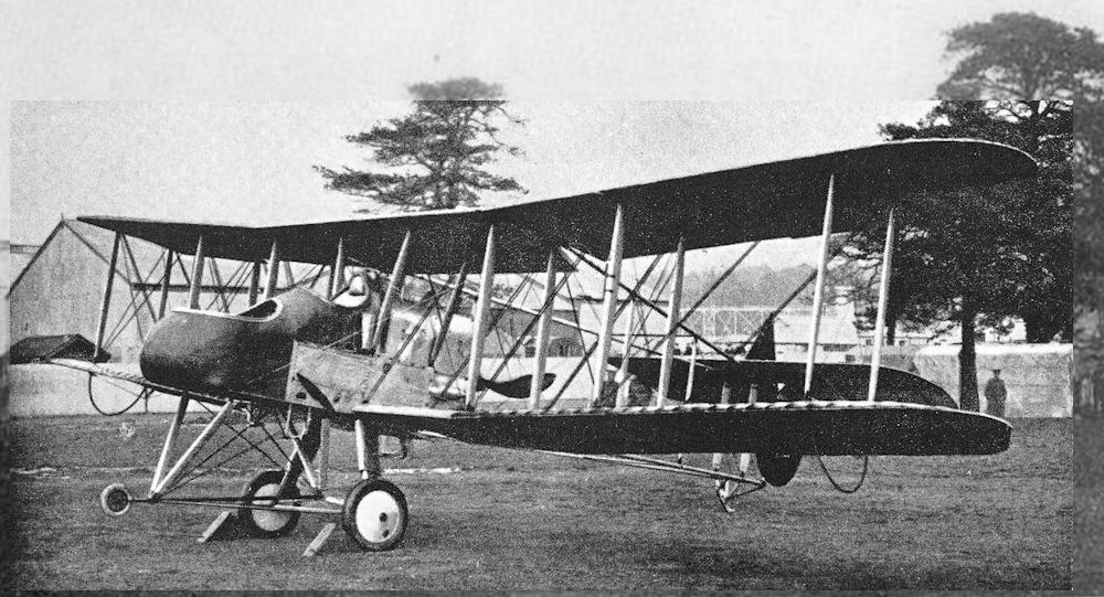
F.E.2a with 100 h.p. Green engine and air-brake on upper centre-section.
RAF FE.2a was a much enlarged aircraft developed in 1914. The prototype flew with a Green engine but the small number of production aircraft used the Beardmore.
RAF FE.2a was a much enlarged aircraft developed in 1914. The prototype flew with a Green engine but the small number of production aircraft used the Beardmore.
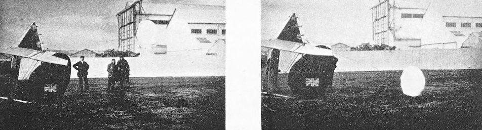
F.E.2a with braking parachute, February, 1915.
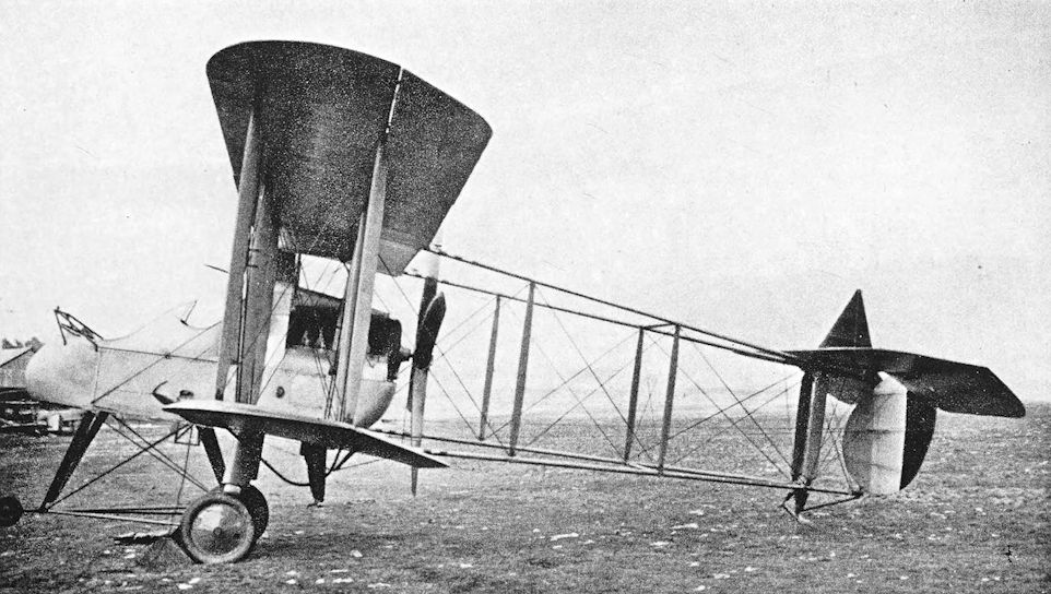
F.E.2b with experimental installation of R.A.F.5 engine.
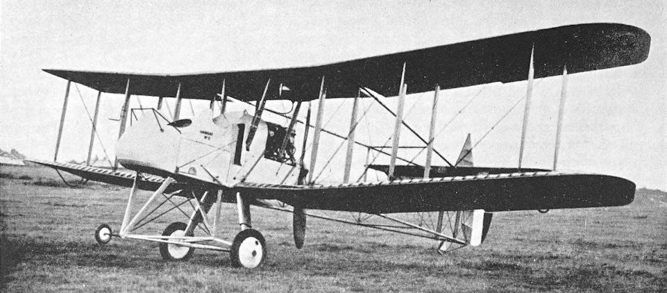
An early F.E.2b with 120 h.p. Beardmore engine.
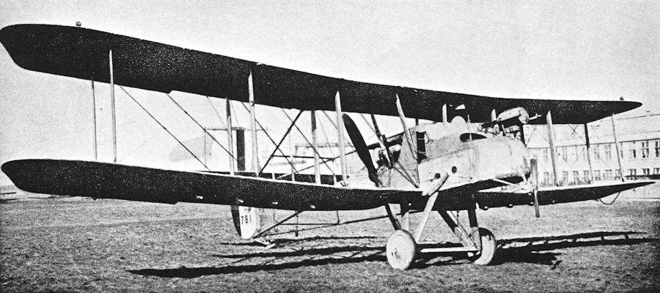
F.E.2b, serial number A.781, with small searchlight coupled to a pair of Lewis guns. There is a wind-driven generator under the chin of the nacelle and small lights under each lower mainplane.
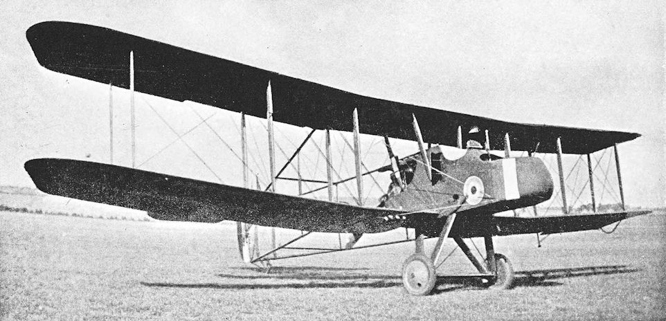
Night-bomber version of the F.E.2b with vee undercarriage. The aircraft is A.5548 of No.64 Training Squadron at Sedgeford 1917
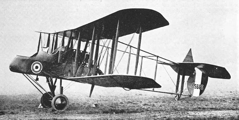
F.E.2b with 160 h.p. Beardmore engine and nose-wheel removed from the undercarriage.
An Airco-built aircraft, B2840, in the so-called D.H.6A configuration with back stagger and reduced rudder and elevator chord.
Production D.H.6 with reduced under-camber, negative stagger, small rudder and small elevators. In the background is an F.E.2b fitted with balloon fenders.
Production D.H.6 with reduced under-camber, negative stagger, small rudder and small elevators. In the background is an F.E.2b fitted with balloon fenders.
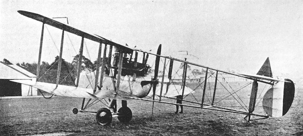
The prototype F.E.2d, showing stack-type exhausts.
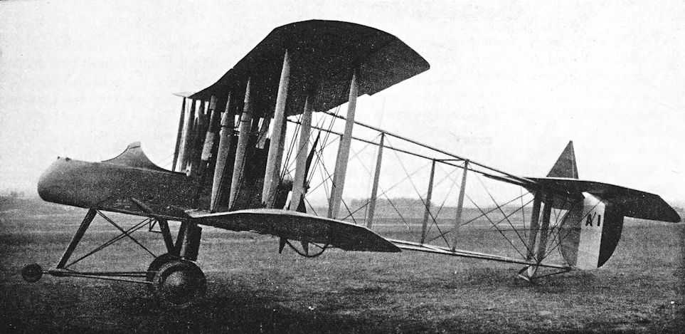
Early production F.E.2d with low-sided pilot’s cockpit.
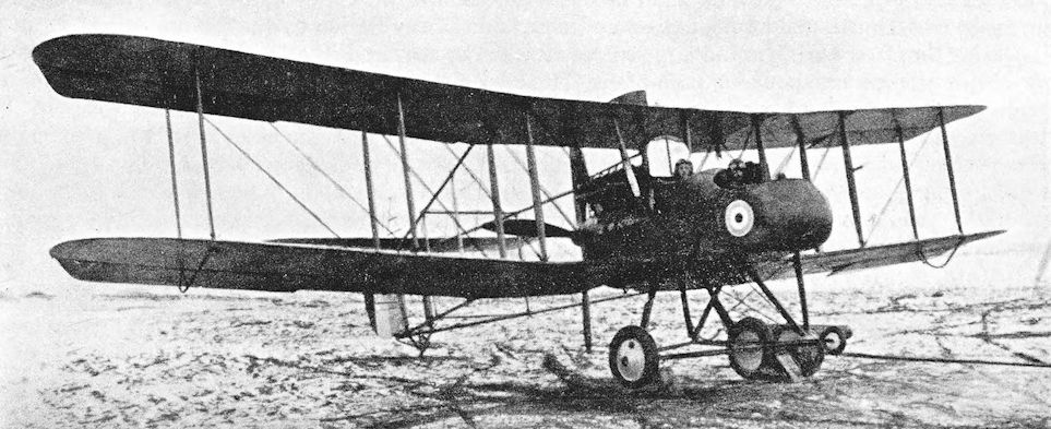
Standard production F.E.2d with high-sided rear cockpit.
R.E.5
THE next R.E. type to see service during the war was the R.E.5. The R.E.3 was virtually the airframe of an H.R.E.2 landplane fitted with a 120 h.p. Austro-Daimler engine; so far as can be ascertained, it saw no war service. References to the R.E.4 describe it as an unequal-span biplane powered by the 120 h.p. Austro-Daimler, but there is no evidence to suggest that the type was ever built.
The R.E.5 was the first type of aeroplane to be produced in appreciable quantity at the Royal Aircraft Factory itself: construction began late in 1913. In the autumn of that year, it was decided that the development of all British lighter-than-air craft should be the responsibility of the Navy. The Army’s airships were handed over to the Navy, and in exchange the sum of £25,000 was transferred from the Admiralty vote to the War Office. Colonel J. E. B. Seely, the Secretary of State for War, used this money to order twenty-four R.E.5s from the Royal Aircraft Factory.
The standard R.E.5 was a two-seat tractor biplane powered by the 120 h.p. Austro-Daimler engine. The engines were built under licence by William Beardmore & Co., and were some of the earliest Beardmore-built aircraft engines. Some of the R.E.5s had genuine Austro-Daimlers, however. The two-bay wings were of equal span, and ailerons were fitted to upper and lower mainplanes. The wing cellule was chiefly remarkable for the interplane bracing, which consisted of Rafwires. The R.E.5 was one of the earliest aeroplanes to be fitted with these streamlined bracing wires in place of the almost universal wire cables which had been used up to that time.
The fuselage was deep, and gave the machine a heavy appearance. The observer was accommodated under the centre-section, and the pilot occupied the rear cockpit. A low aspect-ratio tailplane was fitted, and the elevators were divided; in the vertical tail assembly a large rudder of peculiar shape was attached to a triangular fin. The undercarriage was the usual twin-skid structure.
The engine cowling was a peculiar hooded affair with open front; the radiator was installed behind the engine, within the fuselage and immediately in front of the forward centre-section struts. A manifold exhaust was led round the front of the engine and along the underside of the fuselage to a point just behind the rear undercarriage struts; it was fitted with a silencer.
It seems probable that the first R.E.5s appeared in the early spring of 1914, for by the end of March one of them. No. 380, had been specially modified for climbing and high altitude work. This machine was a single-seater and the upper mainplane had long extensions which were braced by struts to the lower ends of the outer interplane struts. The engine drove a two-bladed airscrew in place of the slender four-blader of the standard R.E.5; and the silencer was removed from the exhaust pipe, which stopped short immediately under the front of the engine. Later, each cylinder had an individual exhaust stub: these stubs protruded through the port side of the cowling at the level of the cylinder heads. Advantage was taken of the inboard position of the radiator to provide a measure of cockpit heating.
The single-seat R.E.5 was handed over to the R.F.C. and was at Netheravon for the Corps’ Concentration Camp in June, 1914. There it was flown to a height of over 17,000 feet by Captain J. H. W. Becke.
By the time of the outbreak of war a number of R.E.5s had been completed. The first to go to France were probably the six which were flown over to reinforce No. 2 Squadron in September, 1914; these machines had originally been allotted to No. 6 Squadron. They were closely followed by the single R.E.5 which belonged to the R.N.A.S. It was flown to Dunkerque by Squadron Commander A. M. Longmore on September 27th, 1914, and three days later set off to bomb Courtrai railway station..No bomb racks were available, so Squadron Commander Longmore’s observer (Flight-Lieutenant Osmond) carried some improvised French bombs in his cockpit and threw them over the side when attacking the target.
When No. 7 Squadron, R.F.C., went to France on April 8th, 1915, it had two Flights of R.E.5s and one of Vickers F.B.5s. The latter were soon replaced by Voisins, however, and on May 9th, 1915, the squadron’s equipment consisted of seven R.E.5s and four Voisins. Two of No. 7’s R.E.5s, each armed with three 20-lb Hales bombs, left St. Omer on April 26th, 1915, in company with seven B.E.2c’s of No. 8 Squadron to bomb enemy troop trains coming from Ghent. The Victoria Cross was won on one of No. 7 Squadron’s R.E.5s by Captain John Aidan Liddell. On July 31st, 1915, while making the routine morning reconnaissance near Bruges with Second Lieutenant R. H. Peck as his observer, a shell burst directly under the R.E.5. A large splinter smashed Liddell’s right thigh. He fainted, and his machine plunged downwards and turned upside down; but he regained consciousness in time to right the R.E.5, and managed to land at the Belgian aerodrome at Furnes. His task was made more difficult by further damage caused by the shell-burst: his control-wheel and throttle had been smashed, and one of the undercarriage struts was broken. Liddell’s V.C. was gazetted on August 23rd, 1915, but he died of his wounds one month after his gallant action.
No further production of the R.E.5 was undertaken after the completion of the original order for 24. The type gradually disappeared, and by September 25th, 1915, only two remained in France: they were with No. 7 Squadron.
At home, one of the standard R.E.5s was used in experiments with air-brakes. As the illustration shows, these brakes consisted of two large flat plates, one on either side, which could be opened outwards until they were normal to the airstream. Air-brakes of this kind were fitted to many R.E.7s.
An experimental installation of a 150 h.p. R.A.F. 4 engine was made in an R.E.5. This engine was the forerunner of the numerous and well-known R.A.F. 4a. The principal difference between the two engines lay in the oil pump: the R.A.F. 4 had a flywheel oil pump, whereas the R.A.F. 4a had a gear pump. The latter engine also had a slightly different type of carburettor.
Another experimental R.E.5 which paved part of the way for the R.E.7 was the machine which had unequal-span wings identical to those of the high-altitude single-seat R.E.5, an oleo undercarriage, and an enlarged fin with rounded leading edge. This aircraft was used to test the bomb-carrying gear for the 336-lb Royal Aircraft Factory bomb, which formed the load of the R.E.7s on many of their bombing raids.
SPECIFICATION
Manufacturers: The Royal Aircraft Factory, Farnborough, Hants.
Power: 120 h.p. Austro-Daimler; 120 h.p. Beardmore; 150 h.p. R.A.F. 4 (experimental installation).
Performance: Maximum speed at ground level: 78 m.p.h. Climb to 6,000 ft: 14 min 40 sec.
Armament: Three 20-lb bombs. The crew carried a rifle or pistols for defence.
Service Use: Western Front: the R.E.5 did not wholly equip any R.F.C. unit, but some were used by Squadrons Nos. 2, 7 (two Flights), 12 (“A” Flight) and 16. Also used by R.N.A.S. at Dunkerque. Training: No. 6 Squadron.
Production and Allocation: Twenty-four R.E.5s were built, twenty-two in 1914 and two in 1915. Eleven went to France and nine to training units.
Serial Numbers: 26, 380, 651.
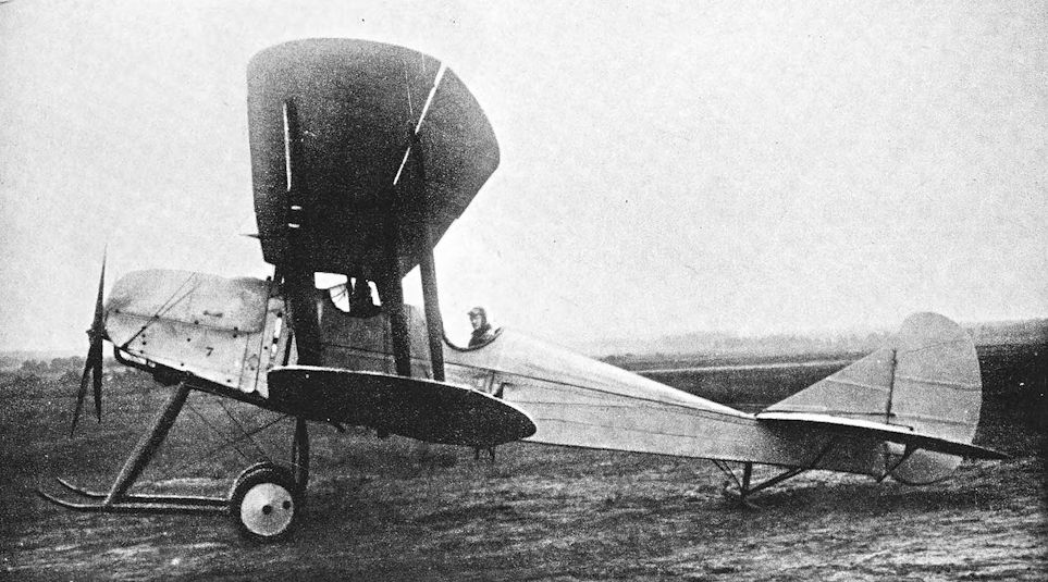
An unidentified standard production R.E.5 at Farnborough on 17 July 1914.
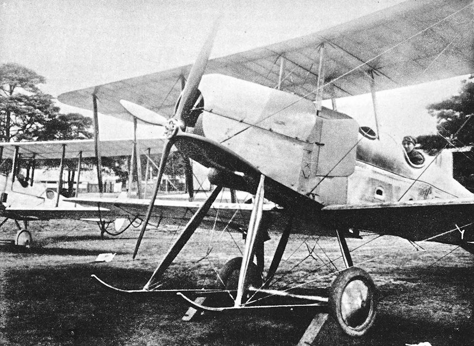
R.E.5 experimentally fitted with air-brakes.
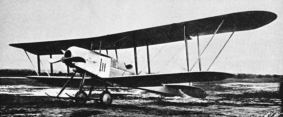
The high-altitude single-seat version of the R.E.5.
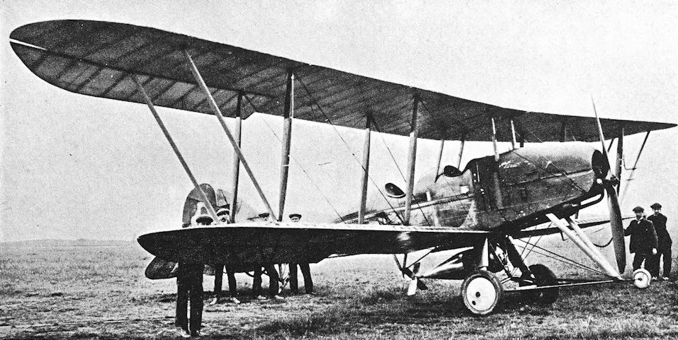
Experimental R.E.5 with oleo undercarriage and R.A.F. 336-lb bomb. The mainplanes are similar to those of the single-seat R.E.5, and an enlarged fin is fitted.
S.E.4
THE S.E.3 was a projected development of the S.E.2a which was never built. It is possible that the design was abandoned in view of the great promise of the S.E.4, for the later machine was certainly a remarkable aeroplane.
The S.E.4 was designed by H. P. Folland, and was built in 1914. Its derivation from the S.E.2 and S.E.2a was reflected in the shape of the fuselage and the vertical tail surfaces, but very great care was taken to minimise drag throughout the design. The engine was a 160 h.p. fourteen-cylinder two-row Gnome rotary which was completely cowled in, and a large spinner was fitted to the airscrew. The combination of a complete cowling and large spinner led to overheating, so an opening was made in the nose of the spinner and a fan was fitted inside it between the roots of the four blades of the airscrew.
The fuselage was of circular cross-section and was covered entirely with plywood. A streamlined transparent cockpit-cover was designed and, after some experiment, was moulded in celluloid. However, no pilot of the time could be induced to fly the S.E.4 with the canopy on, for it was considered too dangerous. The wings were of equal span, and were rigged without stagger. The interplane bracing was unconventional: there was only a single I-strut on each side, with fairly long transverse members at each end connecting with the two spars of each mainplane. The centre-section struts were of similar form, and through their hollow interiors were led the control cables for the ailerons. Control surfaces ran along the entire trailing edge of both upper and lower mainplanes: they acted both as ailerons and as camber-changing flaps. In flight, the flaps could be reflexed slightly in order to reduce drag; and they could be lowered for landing. All gaps between moving and fixed surfaces on the mainplanes and tail-unit were faired over with elastic netting.
The original undercarriage consisted of an inverted tripod which had at its apex a faired leaf spring: a wheel was mounted at each end of this spring. It was found that the S.E.4 rolled too much when taxying, however, so a vee-type of undercarriage was fitted, and once again great care was taken to fair the axle and its junctions with the vee-struts.
When the S.E.4 was designed, the intention was to produce the fastest aeroplane in the world, and this aim was unquestionably achieved. The maximum speed of the machine was over 135 m.p.h., and its initial rate of climb was better than 1,600 feet per minute. The test flying was carried out by Norman Spratt, and Major J. M. Salmond also flew the S.E.4. Both reported favourably on it.
Unfortunately, the landing speed of 52 m.p.h. was considered at that time to be too high for Service use, and production was not undertaken. The big Gnome engine gave a good deal of trouble, and was ultimately replaced by the 100 h.p. Gnome Monosoupape. The reduction in power inevitably had an adverse effect upon the S.E.4’s performance; the maximum speed dropped to 92 m.p.h. Development of the S.E.4 ceased when it was badly damaged by turning over after a wheel collapsed on landing. It saw no operational service.
SPECIFICATION
Manufacturers: The Royal Aircraft Factory, Farnborough, Hants.
Power: 160 h.p. Gnome, later 100 h.p. Gnome Monosoupape.
Dimensions: Span: 27 ft 6 in. Length: 21 ft 4 in. Height: 9 ft with tripod undercarriage, 9 ft 10 1/2 in. with vee undercarriage. Chord: 3 ft 9 1/2 in. Gap: 5 ft 1 in. Stagger: nil. Dihedral: 1° 30'. Incidence: 2°. Span of tail: 10 ft 9 in. Wheel track (tripod undercarriage): 3 ft.
Areas: Wings: upper 98 sq ft, lower 90 sq ft, total 188 sq ft. Tailplane: 18 sq ft. Elevators: 12 sq ft. Fin: 6-5 sq ft. Rudder: 8 sq ft.
Performance: With 160 h.p. Gnome: maximum speed at ground level, 135 m.p.h. With Monosoupape: maximum speed at ground level, 92 m.p.h.; at 7,500 ft: 82-5 m.p.h. Endurance: 1 hour.
Armament: Nil.
Production: One S.E.4 was built in 1914.
Serial Number: 628.
S.E.4a
DESPITE its designation of S.E.4a, the next aeroplane in the S.E. series bore little resemblance to the S.E.4. The S.E.4a appeared in 1915, and was a pretty little single-seat biplane powered by an 80 h.p. Gnome rotary engine. The engine installation resembled that of the later Bristol M.1A monoplane scout, but the large spinner of the S.E.4a incorporated a fan to assist the cooling of the engine.
The fuselage was a conventional structure. The basic wire-braced wooden box-girder was faired by stringers and formers, and the covering was of fabric, with the exception of the metal panels behind the engine. The vertical tail unit is of considerable interest, for in outline and construction it foreshadowed that of the S.E.5.
The single-bay wings were of equal span, and embodied the same full-length ailerons-cum-flaps that had been used on the S.E.4. Structurally the wings were conventional: they had wooden spars, ribs and riblets, and were internally cross-braced. Single-bay interplane bracing was used, with auxiliary flying wires running to a mid-bay position on the upper wing. The wing cellule was remarkable for the absence of an upper centre-section: the upper mainplanes met at a central trestle-shaped cabane formed of two inverted vee-struts. By contrast, there was a wide lower centre-section, with transverse steel tubes to interconnect the lower wing spars.
The S.E.4a proved to be a delight to fly, and provided an excellent mount for Frank Goodden, that great pilot who went to Farnborough as chief test pilot. He frequently displayed his aerobatic prowess on an S.E.4a, and incidentally provided a useful store of experience in his test reports.
The engine cowling proved to be too enclosed, and the 80 h.p. Gnome overheated despite the fan installation. The spinner was removed and a new cowling was fitted; the performance suffered very little from this modification. An alternative installation of the 80 h.p. Le Rhone engine was made, and at least one of the S.E.4a’s had the covering removed from the lower centre-section in order to improve the pilot’s downward view.
Although structurally more suitable for production than the S.E.4, the S.E.4a was not built in quantity. Four were built in 1915, and at the end of that year one of them was at Joyce Green for Home Defence duties.
SPECIFICATION
Manufacturers: The Royal Aircraft Factory, Farnborough, Hants.
Power: 80 h.p. Gnome; 80 h.p. Le Rhone.
Dimensions: Span: 27 ft 5-2 in. Length: 20 ft io| in. Height: 9 ft 5 in. Chord: 4 ft 2 in. Gap: 4 ft 9-06 in. Stagger: 1 ft 6-54 in. Incidence: 40. Span of tail: 10 ft 7 1/2 in. Wheel track: 5 ft 2 in. Airscrew diameter: 8 ft 6 in.
Armament: One rifle; or one Lewis machine-gun mounted centrally above the upper wing, firing forwards above the airscrew.
Service Use: Home Defence: Joyce Green aerodrome.
Production: Four S.E.4a’s were built at the Royal Aircraft Factory in 1915.

The S.E.4, showing its neat engine cowling and the propeller spinner with its internal cooling fan. RAF SE.4 was tested from June 1914 with both 100 and 160 hp Gnome engines, but the undercarriage caused landing problems.

The S.E.4 with vee undercarriage.

RAF SE.4a prototype with Gnome engine and spinner with built-in cooling fan.

S.E.4a with Le Rhone engine.
B.E.9
IN the absence of an interrupter gear to enable a machine-gun to fire forward through the airscrew of an aeroplane, designers evolved many remarkable ways of installing usable armament. Perhaps the most common-sense approach to the problem was to build pusher aeroplanes from which an excellent field of fire could be obtained in all forward directions, but the structure of such aircraft imposed a severe penalty of greatly increased drag.
Attempted solutions appeared in the form of such aircraft as the Mann and Grimmer M.1 and Sage Type 2, but the Royal Aircraft Factory made an even more radical approach to the problem, and in 1915 produced the B.E.9.
This machine was more or less a B.E.2C in which the positions of the engine and observer were transposed. The engine was installed under the leading edge of the centre-section, and a plywood nacelle was mounted in front of the airscrew. As the illustration shows, this nacelle was braced to the undercarriage, and had on its rear wall a ball-race in which the forward end of the airscrew-shaft ran. Standard B.E.2C wings were used, but the span was increased by the insertion of a larger centre-section. A greatly enlarged fin was fitted to balance the increased side area forward of the centre of gravity.
In spite of everything the B.E.9 flew, and was sent to France in the late summer of 1915 to undergo service trials. At Royal Flying Corps H.Q. it was flown by Major (later Air Chief Marshal Sir) Robert Brooke-Popham, who did not condemn it. Later, the B.E.9 (which, for obvious reasons, had become unofficially known as “The Pulpit”) was attached to No. 16 Squadron. Lieutenant D. W. Grinnell-Milne served in No. 16 Squadron while the B.E.9 was there and, in his book Wind in the Wires, wrote of the machine in the following terms:
“There was no communication possible between front and back seat; if anything happened, if the pilot were wounded, or even if nothing more serious occurred than a bad landing in which the machine tipped over on its nose, the man in the box could but say his prayers: he would inevitably be crushed by the engine behind him.
One of these machines was attached to the Squadron in which I served; but by the merciful dispensation of Providence it never succeeded in defeating an enemy craft. Had it done so I have no doubt that brains of the Farnborough Factory would have rejoiced in their war-winning discovery, hundreds of “Pulpits” would have been produced and in a short while we should not have had a living observer in France to tell the experts what it was like in that little box - for I feel sure no civilian expert ever risked his own life in it. However, even in 1915 when almost every new machine was looked at with delighted wonder, it was recognised that in the B.E.9 unsuitability of design had reached its acme. The “Pulpit” was soon returned to the depot.”
But Farnborough must have regarded the B.E.9 as something of a success, for the projected F.E.10 single-seat fighter of 1916 was designed as a development of the B.E.9, and was to have had the cockpit mounted in front of the airscrew. The B.E.9 itself was used in experiments at the Royal Aircraft Factory: at one time a long bar was mounted spanwise across the front cockpit and carried several pitot heads.
A more powerful variant of the basic design was the projected B.E.9a, which was designed round the 150 h.p. R.A.F. 4a engine.
SPECIFICATION
Manufacturers: Constructed at the Royal Aircraft Factory by modifying the B.E.2c, No. 1700, originally built by the British & Colonial Aeroplane Co., Ltd.
Power: 90 h.p. R.A.F.1a.
Dimensions: Length: 30 ft. Chord: 5 ft 6 in. Gap: 6 ft 3 1/2 in. Stagger: 2 ft.
Service Use: Western Front: No.16 Squadron.
Serial Number: 1700.
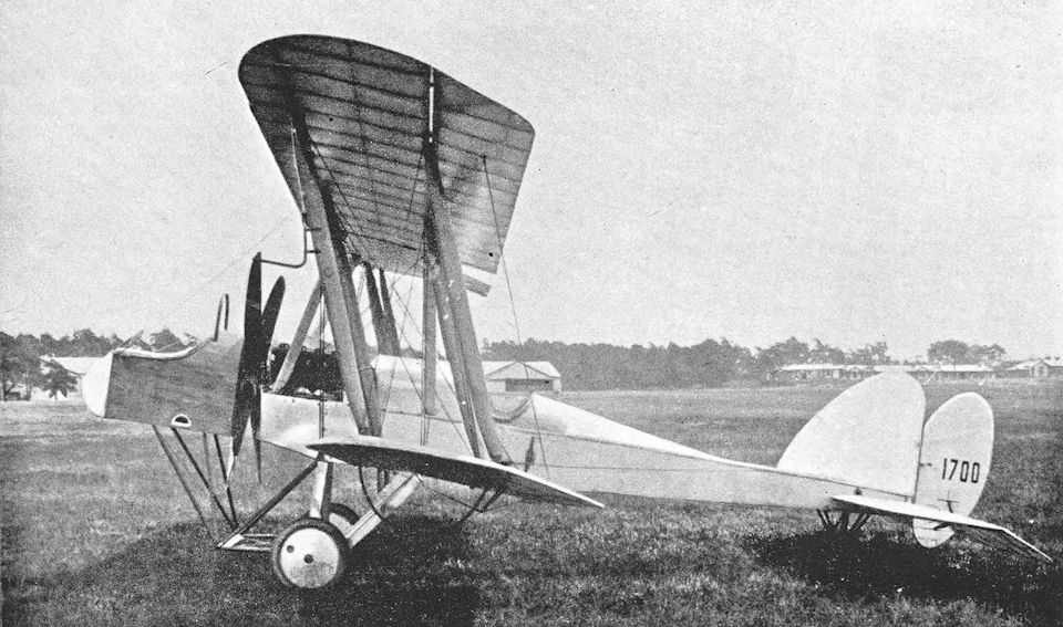
This view of the B.E.9 clearly illustrates the reason for the observer's sense of isolation.
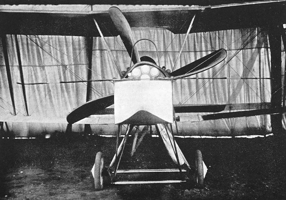
Experimental installation of multiple pitot heads on B.E.9.
F.E.8
It has been said that the F.E.8 was inspired by the D.H.2. Certainly the two machines were similar in general appearance, but the design of the F.E.8 was begun in May, 1915, some months before the D.H.2 appeared. The Factory machine was much later in reaching the front, but that was no fault of the F.E.8, for the prototype was completed in October, 1915.
At that time, no satisfactory interrupter gear was available to British designers, and it was impossible to fit a forward-firing machine-gun to a tractor aeroplane without recourse to the crude expedient of applying steel deflector plates on the airscrew. Designers were therefore more or less compelled to resort to the pusher layout.
The F.E.8 was designed by Mr J. Kenworthy, and was one of the most handsome pusher fighters built during the war: it was a much better-looking aeroplane than the D.H.2. The very wide centresection was bounded on either side by the inboard pair of interplane struts, and was connected to the nacelle by a central cabane of two inverted vee struts. The tail-booms were attached to the extremities of the centre-sections, and converged in side elevation to the main spar of the tailplane. The fin and rudder were symmetrical about the tailplane, and the tail-skid was attached directly to the bottom of the rudder.
The engine was the 100 h.p. Gnome Monosoupape, and the prototype F.E.8 had a large pointed spinner fitted to the four-bladed airscrew. On the first machine, the Lewis gun was mounted low down in the nose with only a few inches of the barrel protruding, and was remotely controlled by the pilot. This arrangement gave rise to many difficulties, not least of which was the impossibility of clearing any stoppages, and in the production F.E.8s the gun was raised to the level of the pilot’s eyes. Spare ammunition drums were carried in external boxes on either side of the cockpit. The spinner was also discarded.
The F.E.8 was beset by several setbacks early in its career. The prototype crashed in November, 1915, and a second machine had to be hurriedly assembled from spare parts. It went to France in December for Service trials, and was immediately favourably received. Production was initiated without delay, but was severely hindered by difficulties with the contractors.
The first production F.E.8s in France were the two which were with No. 29 Squadron on July 1st, 1916, and the first F.E.8 squadron (No. 40) did not arrive on the Western Front until August, 1916. One Flight of the squadron reached France on August 2nd, and the remaining two Flights followed on August 25th. The only other unit to be completely equipped with the F.E.8 was No. 41 Squadron, which arrived in France on October 21st, 1916.
Soon after its introduction into the Service, the F.E.8 figured in a number of spinning accidents and might have acquired a reputation similar to that of the D.H.2 before it was properly understood. The phenomenon of spinning was still an unexplained mystery in 1916; and that provides the measure of the gallantry of that great pilot, Major Frank W. Goodden, who carried out spinning tests of the F.E.8 on August 23rd, 1916. He deliberately spun the machine three times in each direction from 3,500 feet, and each time regained full control by means of control movements which, decades later, were still being taught as the standard method of spin recovery.
With that unpleasant rumour scotched, the F.E.8 became quite popular with pilots, for it was a pleasant flying machine. It was tractable in the air, but rather stiffer on the controls than the D.H.2. Unfortunately, however, the F.E.8 was practically obsolete by the time it reached the front, and its pusher layout denied it the performance needed to meet contemporary German fighters.
On March 9th, 1917, nine F.E.8s of No. 40 Squadron were attacked by Jagdstaffel 11, led by Manfred von Richthofen. The fight lasted half an hour. Four F.E.8s were shot down and four others forced down damaged, whilst the pilot of the last machine was wounded. His F.E.8 caught fire before he landed, but he jumped clear just before the machine struck the ground.
Within a few weeks of this debacle, No. 40 Squadron was re-equipped with Nieuport Scouts; but with No. 41 Squadron the F.E.8 remained in service, the last pusher fighter in the field, until July, 1917. Among its last duties were trench-strafing sorties during the Battle of Messines in June, 1917.
The F.E.8 was also flown with the 110 h.p. Le Rhone and 110 h.p. Clerget engines, but the Monosoupape Gnome remained the standard power unit.
SPECIFICATION
Manufacturers: The Royal Aircraft Factory, Farnborough, Hants.
Other Contractors: The Darracq Motor Engineering Co., Ltd., Townmead Road, Fulham, London, S.W.6; Vickers, Ltd. (Aviation Department), Imperial Court, Basil Street, Knightsbridge, London, W.6 (production at the Weybridge works). Power: 100 h.p. Gnome Monosoupape; 110 h.p. Le Rhone; 110 h.p. Clerget.
Dimensions: Span: 31 ft 6 in. Length: 23 ft 8 in. Height: 9 ft 2 in. Chord: 4 ft. Gap: 4 ft 6 in. Stagger: nil. Dihedral: 4. Incidence: 4. Span of tail: 10 ft 8-4 in. Wheel track: 5 ft 2 in. Airscrew diameter: 8 ft.
Areas: Wings: 218 sq ft. Tailplane: 14-5 sq ft. Elevators: 12 sq ft. Fin: 2-5 sq ft. Rudder: 6-5 sq ft.
Weights {lb) and Performance:
Engine Monosoupape Le Rhone Clerget
Date of Trial Report - April, 1916 -
Type of airscrew used on trial T.7928 T.7928 -
Weight empty 895 960 -
Military load 39 50 -
Pilot 180 180 -
Fuel and oil 232 280 -
Weight loaded 1,346 1,470 1,390
Maximum speed (m.p.h.) at
ground level 94 93-6 97
10,000 ft - 89 -
m. s. m. s. m. s.
Climb to
2,000 ft - - 2 10 - -
3,000 ft - - 4 15 - -
5,000 ft 7 30 - - - -
6,000 ft - - 8 20 - -
6,500 ft 11 00 - - - -
7,000 ft - - 10 10 - -
8,000 ft - - 12 10 - -
9,000 ft - - 14 00 - -
10,000 ft 17 30 17 15 - -
Service ceiling (feet) 14,500 - -
Endurance (hours) 21 - -
Tankage: Petrol: 29 gallons. Oil: 6 3/4 gallons.
Armament: One Lewis machine-gun on a bracket immediately in front of the cockpit.
Service Use: Western Front: R.F.C. Squadrons Nos. 5, 29, 40 and 41. Training: used at various training aerodromes, including No. 10 Reserve Squadron, Joyce Green and the Advanced Air Firing School at Lympne.
Production and Allocation: Serial numbers indicate that 297 F.E.8s were ordered, including the two prototypes which were built at the Royal Aircraft Factory in 1915. A total of 182 were delivered to the R.F.C.: of these, 147 went to the squadrons in France, two to Home Defence units in 1917, and the remainder to training units.
Serial Numbers: 3689-3690: allotted for F.E.8s, apparently for Admiralty. 6378-6477: built by Darracq. 7456- 7457: prototypes built by Royal Aircraft Factory. 7595-7644: built by Vickers. A.41-A.65. A.4869-A.4987 and A.5491: built by Darracq.
Notes on Individual Machines: Used by No. 40 Squadron: 6388, 6397, 6399, 6419, 6423, 6425, 6426, 6428, 6455, 6456, 6469, 7606, 7622 (also used by No. 41 Squadron), 7627, 7635, A.4871. Used by No. 41 Squadron: 6394, 6416, 6417, 6429, 6431, 6432, 6437, 6447, 6453, 6470, 6471, 7613, 7615, 7616, 7622 (also used by No. 40 Squadron), 7626, 7630, 7643, A.4870, A.4873, A.4915. Other machines: 6401: No. 10 Reserve Squadron. A.4944: Advanced Air Firing School, Lympne.
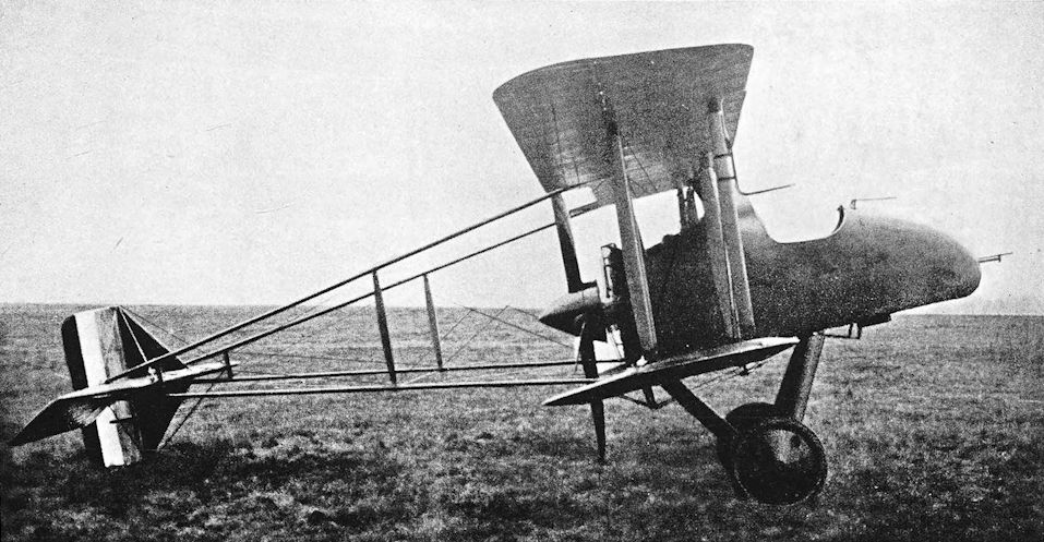
The prototype F.E.8 with spinner and remotely-controlled Lewis gun. This type was under consideration, along with the DH2, for the RFC's fighter requirement in mid 1915. An effective fighter type was needed in France as aircraft began to play an increasing part in the war.
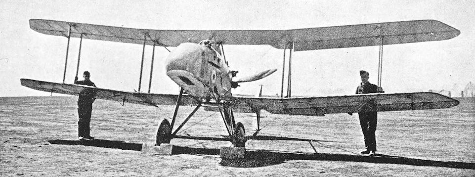
Production F.E.8 with gun-mounting in front of cockpit.
R.E.7
THE R.E.7, which appeared in 1915, was developed from the R.E.5 and was intended to carry greater loads. It was a large two-bay biplane with long strut-braced extensions on the upper wings. An unusual feature of the wing cellule was the absence of any conventional upper centre-section: there was a central cabane of inverted vee struts after the fashion of several contemporary enemy types.
Structurally the R.E.7 was distinguished by a fuselage of composite construction. The portion aft of the cockpits was a conventional cross-braced wooden box girder; but the forward portion was made of steel tubing. The original engine was the 120 h.p. Beardmore, cowled in a manner reminiscent of the R.E.5 and with a similar exhaust manifold and silencer. The undercarriage was the sturdy oleo structure with small nose-wheel which had been used on the F.E.2a and 2b. The tail surfaces were of generous size and characteristic outline.
Many R.E.7s had air-brakes similar to those which had been tested on an R.E.5: they were attached to the fuselage sides in line with the forward cabane struts, and opened outwards.
Because it offered the prospect of carrying a useful war-load, the R.E.7 was ordered in considerable quantities from several contractors. Deliveries began late in 1915, and by the end of that year sixteen had been handed over to the R.F.C. The only unit to go to France equipped throughout with R.E.7s was No. 21 Squadron, which arrived there on January 23rd, 1916.
The R.E.7 thus went into action at the time when the Fokker monoplane was at the zenith of its career, and its earliest duties included escorting the reconnaissance two-seaters over the lines. Since the R.E.7’s observer occupied the forward cockpit, however, he was no more able to use a gun effectively than were his colleagues in the B.E.2c’s, and the R.E.7 was not conspicuously successful as an escort machine.
Together with No. 12 Squadron, No. 21 was given the duty of performing the special strategical and patrol work required by General Headquarters in the preparations for what was to have been a major Allied offensive, launched in July, 1916. The enemy forestalled this plan by opening an offensive on February 21st, 1916. The Allies’ plans had to be radically altered, and the offensive which was launched on July 1st, 1916, was the beginning of the Battles of the Somme. For their special duties Nos. 12 and 21 Squadrons were based at R.F.C. Headquarters, and provided the basis for the formation of the 9th Wing.
It was as a bomber that the R.E.7 found its true metier, however. Its ability to lift a comparatively heavy war-load was enhanced by the use of the 150 h.p. R.A.F. 4a and 160 h.p. Beardmore engines; the majority of No. 21 Squadron’s R.E.7s had the former power unit. The installation of the R.A.F. 4a was characterised by the inevitable large air-scoop and funnel exhausts, and was not beautiful.
The R.E.7 could carry the 336-lb Royal Aircraft Factory bomb. This bomb was carried under the fuselage: its nose was held in a bracket attached to the rear central vee-strut of the undercarriage and its tail by an inverted tripod directly under the pilot’s seat.
In preparation for the Somme offensive No. 21 Squadron moved to Fienvillers on June 19th, 1916, and on the 30th of that month six of the squadron’s R.E.7s bombed the railway station at St. Sauveur.
On the following day six machines bombed Bapaume, known to contain a German headquarters, and cut the railway line south of the town. In the afternoon of July 2nd, six R.E.7s again attacked Bapaume: each aircraft dropped a 336-lb bomb, and those which fell on ammunition dumps started fires which could still be seen after nightfall. Cambrai station was the target for the 336-lb bombs of three R.E.7s on July 3rd, and suffered again at 4.30 a.m. on July 9th when six of No. 21 Squadron’s machines attacked with the big R.A.F. bombs.
At this time No. 21 Squadron had fourteen R.E.7s, four B.E.2c’s and one B.E.2e, but in August, 1916, the squadron was withdrawn to Boisdinghem for re-equipment with B.E.12s.
The R.E.7’s operational career was comparatively brief and its exploits virtually unknown, but it continued in service for experimental and training purposes until 1918. Other engines were fitted; in some cases the R.E.7 airframe obviously provided no more than a test vehicle. The 190 h.p. Rolls-Royce Falcon, 250 h.p. Rolls-Royce Mk. Ill (Eagle III) and 200 h.p. R.A.F. 3a were all tried, and at least one machine had a 225 h.p. Sunbeam engine.
The Eagle-powered R.E.7 had a large frontal radiator and a pair of splayed-out funnel exhausts; whilst the R.A.F. 3a had a somewhat makeshift arrangement of radiators and a single central exhaust stack.
Most remarkable of all the R.E.7s were the three-seat conversions, however. A third cockpit was made immediately behind the pilot’s cockpit, and was fitted with an early Nieuport-type of rotating gun-mounting. At least two R.E.7s were modified in this way: these were No. 2348 and No. 2299. The former had the 160 h.p. Beardmore, but was also flown as a two-seater with the 150 h.p. R.A.F. 4a; the latter was powered by the 250 h.p. Rolls-Royce engine, and had the low-sided front cockpit which appeared on some R.E.7s, particularly those which were not fitted with air-brakes. An R.E.7 with the 250 h.p. Rolls-Royce was used by No. 20 Squadron from the early autumn of 1916 until it crashed on January 31st, 1917. This was probably the R.E.7 three-seater which arrived at No. 2 Aircraft Depot, Candas, on August 20th, 1916.
Among the last duties of the R.E.7 was the towing of sleeve targets for aerial gunnery practice, and the machine must have been one of the earliest target tugs to be used.
SPECIFICATION
Manufacturing Contractors: The Austin Motor Co. (1914), Ltd., Northfield, Birmingham; The Coventry Ordnance Works, Ltd., Coventry; D. Napier & Sons, Acton, London, W.; The Siddeley-Deasy Motor Car Co., Ltd., Park Side, Coventry.
Power: 120 h.p. Beardmore; 160 h.p. Beardmore; 150 h.p. R.A.F. 4a; 190 h.p. Rolls-Royce Falcon; 250 h.p. Rolls-Royce Mk. Ill (284 h.p. Eagle HI); 200 h.p. R.A.F. 3a; 225 h.p. Sunbeam.
Dimensions: Span: upper 57 ft, lower 42 ft. Length: 31 ft 10 1/2 in. Height: 12 ft 7 in. Chord: 6 ft. Gap: 6 ft 6 in. Stagger: 2-89 in. with Beardmore and R.A.F. 4a engines, 11 in. with Eagle. Dihedral: 2° 30'. Incidence: with Beardmore engines, 3° 06'; with R.A.F. 4a, 4° with 30' wash-out on starboard wing; with Eagle, 3° 06' with 30' wash-out on starboard wing. Span of tail: 16 ft 11 in. Airscrew diameter: R.A.F. 4a, 10 ft; 160 h.p. Beardmore, 9 ft; 250 h.p. Rolls-Royce, 10 ft 3 in.
Areas: Wings: 548 sq ft. Tailplane: 50 sq ft. Elevators: 32 sq ft. Fin: 13 sq ft. Rudder: 16 sq ft.
Armament: One 336-lb R.A.F. bomb or two 112-lb bombs augmented by 20-lb bombs. Makeshift arrangements of rifles, pistols or a Lewis machine-gun were used for defence. The three-seater had a Lewis gun on a Nieuport ring-mounting on the rear cockpit, and a second Lewis was provided for the occupant of the front cockpit. There are references to a three-seat R.E.7 with a synchronised Vickers machine-gun for the pilot.
Service Use: Western Front: No. 21 Squadron, R.F.C., and part of No. 12 Squadron. One three-seat R.E.7 was used by No. 20 Squadron. Training: No. 35 Reserve Squadron, Northolt; School of Aerial Gunnery, Hythe.
Tankage (in gallons):
160 h.p. Beardmore R.A.F. 4a Eagle
Petrol:
Main pressure tank - 43 -
Auxiliary pressure tank - 15 -
Service tank - 8
Total 61 66 74
Oil 8 8 1/4 8
Water 6 - 12-6
Weights (lb) and Performance:
Engine 120 h.p. Beardmore 160 h.p. Beardmore R.A.F. 4a R.A.F. 4a Falcon Eagle
- - With 336-lb bomb Without bomb - -
No. of Trial Report - - M.26 - - -
Date of Trial Report - May, 1916 May, 1916 - - August, 1916
Type of airscrew used on trial - - T.6447 - - T.28023
Weight empty - 2,285 2,170 -. - 2,702
Military load - 160 410 - - 442
Crew - 360 320 - - 360
Fuel and oil - 485 549 - - 605
Loaded - 3,290 3,449 3,139 3,280 4,109
Maximum speed (m.p.h.) at
ground level 82 913 849 84 - -
5,000 ft 73 - - - - -
7,000 ft - - 82 - - -
10,000 ft - 83 - - 86 -
10,120 ft - - - - - 88-2
15,000 ft - - - - 72 -
m. s. m. s. m. s. m. s. m. s. m. s.
Climb to
5,000 ft 30 35 13 25 - - - - - - - -
6,000 ft - - 16 40 29 30 16 30 - - 11 45
6,500 ft - - 18 30 - - - - - - 13 00
9,000 ft - - - - 64 00 - - - - - -
10,000 ft - - 31 50 - - 38 30 24 15 23 30
15,000 ft - - - - - - - - 53 30 - -
Service ceiling (feet) - - 6,500 - - -
Endurance (hours) - - 6 - - -
Production and Allocation: About 250 R.E.7s were built. A total of 224 were delivered to R.F.C. units: fifty-eight went to France, nineteen to Home Defence Units, and 147 to training stations.
Serial Numbers: 2185-2234: built by Coventry Ordnance Works. 2236-2265: built by Austin Motor Co. Between and about 2287 and 2300; batch probably built by Napier. 2348-2447: built by Siddeley-Deasy.
Notes on Individual Machines: 2194: No. 35 Reserve Squadron, Northolt. 2299: three-seater with 250 h.p. Rolls- Royce engine. 2348: three-seater with Beardmore engine; also flown as two-seater with R.A.F.4a.
Costs:
Airframe without engine, instruments and guns £1,886
Engines:
120 h.p. Beardmore £825
160 h.p. Beardmore £1.045
R.A.F.4a £836
R.A.F.3a £1,210
250 h.p. Rolls-Royce Mk. Ill £1,430
190 h.p. Rolls-Royce £1,210

R.E.7, serial number 2287, with Beardmore engine.

Трехместная модификация R.E.7 с двигателем "Санбим".
R.E.7 three-seater with Rolls-Royce Eagle engine.
R.E.7 three-seater with Rolls-Royce Eagle engine.

R.E.7 with Rolls-Royce Eagle engine.

R.E.7 No 2348 after modification as a three-seater and carrying the 336 lb bomb. The aircraft also appears to have reverted to the 160hp Beardmore engine. This aeroplane, No. 2348, was also flown as a two-seater with the R.A.F. 4a engine.

RAF R.E.7 в стандартной английской боевой окраске.
The R.E.7 with 150 h.p. R.A.F.4a engine, No.2400, one of 100 built by The Siddeley Deasy Motor Car Co.
The R.E.7 with 150 h.p. R.A.F.4a engine, No.2400, one of 100 built by The Siddeley Deasy Motor Car Co.

R.E.7 with R.A.F. 3a engine.
B.E.12, 12a and 12b
WHEN it became obvious that the Fokker monoplane was going to be a serious menace to Allied aircraft generally, urgent requests were sent home for single-seat fighters to protect the artillery-observation and bombing machines. In view of the urgency of the demand, the Royal Aircraft Factory did not attempt to produce a new design: instead the B.E.2c was chosen as the basis for a single-seat fighter powered by a 150 h.p. R.A.F. 4a engine. The prototype was a straightforward conversion of the Bristol-built B.E.2C No. 1697. The fuselage was not greatly modified to accept the bigger engine, and the upper longerons remained straight and continuous; there was only a small air-scoop above the cylinders; and the exhaust arrangements were clumsy, as the illustration shows.
Production was undertaken by some of the firms who had been contractors for the B.E.2C. The forward end of the fuselage was modified in production aircraft by dropping the upper longerons a few inches in front of the cockpit: this made it possible to fit a large main fuel tank between the centre-section struts, and a gravity tank was fitted under the port upper mainplane as on the B.E.2d. The engine installation was also modified, and a large air-scoop was fitted above the cylinders. The exhaust system was simplified and each cylinder bank had a separate stack outlet. The cowling round the lower part of the engine resembled that of the R.E.8: when the very deep cowling was standardised for the R.E.8 it was also applied to later B.E.12s.
At first, the original triangular fin and rectangular tailplane were fitted; but the larger rounded fin was used when it was standardised for all B.Es on the introduction of the B.E.2e, and the later tailplane with raked tips was fitted to the late production B.E.12s.
The B.E.12s came along in time to benefit from the introduction of the Vickers machine-gun interrupter gear, and the standard armament consisted of a fixed Vickers gun on the port side of the fuselage. The Vickers gear was a purely mechanical one, driven from the rear end of the engine crankshaft: the main connecting rod between the engine drive and the gun was a long one, and some trouble was experienced with the gear owing to backlash. The Vickers was sometimes supplemented by a Lewis gun on a Strange mounting on the starboard side; and some B.E.12s had two Strange-mounted Lewis guns, one either side.
The first B.E.12 in France was the single machine which was with No. 10 Squadron on July 1st, 1916; but the first squadron to go to France fully equipped with the type was No. 19, which reached its aerodrome at Fienvillers on August 1st, 1916. No. 21 Squadron had been withdrawn to Boisdinghem on July 28th, for re-equipment with B.E.12s, and returned to the Front with its new machines on August 25th.
As a fighter the B.E.12 proved to be a dismal failure. The mere actions of installing a more powerful engine and reasonably useful armament in the B.E.2c airframe could not produce a good fighter, for the aerodynamics of the aircraft remained unchanged and it was therefore so stable that it could not be manoeuvred quickly.
The B.E.12 was withdrawn from fighting duties in the middle of September, 1916, and was thereafter used as a single-seat bomber. General Trenchard bluntly reported: “I realise fully that I shall lose two squadrons if I stop using the B.E.12 and delay, I suppose, for some considerable period two other squadrons. Although I am short of machines to do the work that is now necessary with the large number of Germans against us, I cannot do anything else but to recommend that no more be sent to this country.”
The B.E.12s had in fact been used as bombers before their withdrawal from fighting duties, but no matter how they were used their losses were heavy. On September 24th, 1916, a formation of five of No. 19 Squadron’s B.E.12s were attacked over Havrincourt Wood by two enemy fighters which completely outmanoeuvred them and shot down two of the B.Es. On October 16th, two of seven B.E.12s of No. 19 Squadron were shot down after bombing Ruyaulcourt.
In December, 1916, No. 19 Squadron was re-equipped with Spad S.7s, and No. 21 Squadron received its R.E.8s in February, 1917. After that time the only unit which continued to use the B.E.12 in France was the Special Duty Flight.
The type was used in small numbers in the Near East and in Macedonia. In July, 1916, No. 17 Squadron arrived at Mikra Bay near Salonika, equipped with B.E.2c’s and B.E.12s. An officer of this squadron, Captain G. W. Murlis-Green, achieved an unusual amount of success with the B.E.12. Enemy two-seaters fell to his attacks on December 13th, 1916, January 4th and January 14th, 1917.
Three of No. 17 Squadron’s B.E.12s and one from No. 47 Squadron were sent to form part of the strength of the composite fighting squadron which was formed in March, 1917, and operated from Hadzi Junas to oppose the activities of Kampfgeschwader I. This German bomber squadron had come to Hudova from Bucharest after a bombing campaign against Roumania. On March 18th the British composite squadron twice forced the enemy to abandon attempted raids: Captain Murlis-Green shot down one of the enemy bombers and damaged another. Next day he shot down an Albatros two-seater.
When the enemy cruiser Goeben ran aground after her sortie from the Dardanelles in January, 1918, three B.E.12s of No. 17 Squadron and three of No. 47 Squadron were among the many aircraft which bombed her. When the Armistice was signed, No. 17 Squadron still had one B.E.12 on its strength, and another was with No. 150 Squadron.
In Palestine, the short-lived unit known as “B” Flight was created from No. 23 Training Squadron in Egypt for bombing duties connected with the third Battle of Gaza. The Flight arrived at Weli Sheikh Nuran on October 30th, 1917, equipped with ten aeroplanes, B.E.2e’s and B.E.12s; and was disbanded early in December.
Three B.E.12s formed the equipment of the detachment of No. 14 Squadron which became known as “X” Flight, and was located at Aqaba for work with the Arab forces. The chief duty of this Flight was to reconnoitre the Hejaz railway, a duty which the single-seat B.E. 12s continued to perform after the Flight’s strength was increased by two B.E.2e’s and a D.H.2. The B.E. 12s usually carried twelve or sixteen 16-lb bombs to drop on any suitable target.
The B.E.12 was closely followed by another single-seat scout powered by the 150 h.p. R.A.F. 4a engine. The new machine had the same wing arrangement as the B.E.2e, and was designated B.E.12a. The fuselage was identical to that of the B.E.12; the wings had a single bay of bracing, and had the long wire-braced extensions on the upper mainplanes which had characterised the B.E.2e. In its original form, however, the B.E. 12a had ailerons on the upper wings only: these control surfaces had enormous horn-balances which were probably intended to improve manoeuvrability.
On its flight trials the B.E.12a almost killed its pilot, Captain L. R. Tait-Cox, doubtless because the ailerons were over-balanced. The design was modified, and tests of the horn-balanced ailerons were continued on the F.E.9. The B.E.12a was thereafter fitted with standard B.E.2e wings, which had ailerons on both upper and lower surfaces; the ailerons were coupled by light struts.
In this modified form the machine was first designated B.E.12Ae, a somewhat cumbersome appellation which was dropped in favour of the original name B.E.12a.
All B.E.12a’s had the enlarged fin and the B.E.2e-pattern tailplane with raked tips.
After the failure of the B.E.12 and General Trenchard’s condemnation of it, it was hardly to be expected that the B.E.12a would be issued to squadrons. The only R.F.C. unit to use the B.E.12a in France was the Special Duty Flight of the 9th (H.Q.) Wing: the Flight had one or two B.E.12a’s for a short period in the summer of 1917.
A few went to Palestine, where they were used by No. 67 (Australian) Squadron: that unit had five B.E.12a’s on October 27th, 1917. These B.E.12a’s were relinquished on February 13th, 1918 (by which time No. 67 had become No. 1 Squadron, Australian Flying Corps), when they were handed over to the nucleus Flight of No. 142 Squadron at Julis.
The B.E.12 and 12a were used with fair success by Home Defence squadrons from the end of 1916. On B.E.12 No. 6610, Lieutenant L. P. Watkins of No. 37 Squadron shot down the Zeppelin L.48 at 3.28 a.m. on June 17th, 1917: the flaming hulk fell slowly from about 14,000 feet and crashed at Holly Tree Farm near Theberton.
On the night of the last enemy aeroplane attack on England, May 19th/20th, 1918, eight B.E.12s went up to meet the bombers. Among the 76 other Home Defence machines which took off that night were three B.E.12b’s.
The B.E.12b was a 1917 development of the B.E.12, specifically intended for Home Defence use. It was the most powerful of all the B.E. series: its engine was the 200 h.p. Hispano-Suiza, the installation of which was very similar to that of the S.E.5a, and had the same long exhaust pipes on each side. Some B.E.12b’s had large flame dampers at the end of the exhaust pipes. An S.E.5a-type head-rest was fitted behind the cockpit. The main fuel tank was identical to that fitted to the B.E.12 and 12a, but was installed backwards. There was a wedge-shaped portion on top of this tank which, on the B.E.12 and 12a, faired off the rear end of the large air-scoop above the engine; and this remained visible on the B.E. 12b. Presumably this fairing created less drag in the reversed position. Navigation lights were fitted to the lower mainplanes.
The armament of the B.E. 12b consisted of a pair of Lewis guns on a special mounting attached to the centre-section; the starboard gun was fitted with a Hutton illuminated sight. The main portion of the gun-mounting consisted of a piece of steel tubing which was pivoted on a cross-bar running between the rear centre-section struts. It was connected by a cable running over a pulley at the top of the front starboard centre-section strut to a large, imposing lever mounted externally on the starboard side. With the lever fully aft the guns fired forward over the airscrew; when the lever was fully forward the guns came into the vertical position for reloading or upward firing. The guns were fired by a small handle at the top of the long lever, connected to the guns by a Bowden cable.
Well over a hundred B.E.12b’s were built, but only thirty-nine were issued to units: of that total thirty-six went to the Home Defence squadrons.
SPECIFICATION
Manufacturing Contractors: The Coventry Ordnance Works, Ltd., Coventry; The Daimler Co., Ltd., Coventry; The Standard Motor Co., Ltd., Cash’s Lane, Coventry.
Power: B.E.12 and 12a: 150 h.p. R.A.F. 4a. B.E.12b: 200 h.p. Hispano-Suiza.
Dimensions: Span (B.E.12 and 12b): 37 ft; (B.E.12a) upper 40 ft 9 in., lower 30 ft 6 in. Length (B.E.12 and 12a): 27 ft 3 in. Height (B.E.12): 11 ft 1 1/2 in., (B.E.12a) 12 ft. Chord: 5 ft 6 in. Gap: 6 ft 3 1/4 in. Stagger: 2 ft. Dihedral: 3 30'. Incidence (B.E.12): 4 09', (B.E.12a) 4 15'. Span of tail: 14 ft (15 ft 6 in. on early B.E.12s). Wheel track: 5 ft 9 in. Tyres: 700 X 100 mm. Airscrew diameter (B.E.12 and 12a): 9 ft 9 in.
Areas: Wings (B.E.12 and 12b): 371 sq ft, (B.E.rna) 360 sq ft. Tailplane: 24 sq ft. Elevators: 21 sq ft. Fin: 8 sq ft. Rudder: 11-8 sq ft.
Tankage: Petrol: main pressure tank 45 gallons; service gravity tank 12 gallons; total 57 gallons. Oil: 6 gallons.
Weights (lb) and Performance: B.E.12: C.F.S. Trials. Speed, May 3rd and 11 th, 1916; climbing, May 4th, 1916. B.E.12a: C.F.S. Trials. Speed, November 21st, 1916; climbing, November 15th, 1916.
B.E.12 B.E.12a
Weight empty 1.635 1,610
Military load 80 80
Pilot 180 180
Fuel and oil 457 457
Weight loaded 2.352 2,327
Maximum speed (m.p.h.) at
ground level 102 -
3,100 ft - 99-5
5,100 ft - 95-5
6,500 ft 97 -
7.050 ft - 89-5
8,000 ft 94 -
8,500 ft - 83-5
10,000 ft 91 -
I 1,000 ft - 78-5
12,000 ft - 72
m. s. m. s.
Climb to
1,000 ft 1 30 1 35
2,000 ft 3 30 3 20
3,000 ft 5 50 5 00
4,000 ft 8 20 7 05
5,000 ft 11 05 9 10
6,000 ft 14 00 I I 20
7,000 ft 17 20 13 45
8,000 ft 21 50 16 20
9,000 ft 27 00 19 30
10,000 ft 33 00 24 15
I 1,000 ft 40 00 31 45
12,000 ft 47 30 44 00
13,000 ft 54 00 59 30
14,000 ft 62 00 - -
Service ceiling (feet) 12,500 -
Endurance (hours) 3 -
Armament: B.E. 12: two fixed Lewis machine-guns, one on either side of the fuselage on a Strange mounting; or one fixed Vickers machine-gun mounted on the port side of the fuselage, synchronised by Vickers synchronising gear to fire forward through the revolving airscrew. In some cases this gun was supplemented by a single Lewis gun on a Strange mounting on the starboard side of the fuselage. At least one of the B.E. 12s used by No. 47 Squadron was armed with three Lewis guns. Bomb load could consist of two 112-lb bombs or up to sixteen 16-pounders. B.E. 12a: fixed Vickers gun on port side of fuselage as on B.E. 12. B.E. 12b: twin Lewis guns on special mounting on centre-section; some B.E.12b’s had a single Lewis gun above the centre-section, and carried bombs under the lower wings.
Service Use: B.E.12: Western Front: R.F.C. Squadrons Nos. 10, 19 and 21; Special Duty Flight, 9th (H.Q.) Wing. Macedonia: R.F.C. Squadrons Nos. 17, 47 and 150; Composite Fighting Squadron at Hadzi Junas. Palestine: “B” Flight, R.F.C., formed from No. 23 Training Squadron; “X” Flight at Aqaba; No. 144 Squadron. Home Defence: R.F.C. Squadrons Nos. 36, 37, 50, 51, 76 and 77. Training: No. 31 Training Squadron, Wyton; No. 42 Training Squadron, Hounslow; No. 23 Training Squadron, Egypt. B.E. 12a: Western Front: Special Duty Flight of 9th (H.Q.) Wing. Palestine: No. 67 (Australian) Squadron; No. 142 Squadron. Home Defence: R.F.C. Squadrons Nos. 50, 76 and 112. Training: No. 89 (Reserve) Squadron, Canada. B.E. 12b: Home Defence: R.F.C. Squadrons Nos. 50, 51, 76 and 77.
Production and Allocation: The total number of B.E. 12s and B.E.12a’s issued to units of the R.F.C. and R.A.F. was 468. Of that total, 130 went to squadrons in France, sixty-seven to the Middle East, 101 to Home Defence squadrons, and the remaining 170 went to training units. On October 31st, 1918, the R.A.F. had sixty-four B.E.12S and B.E.12a’s on charge. One was in France; twenty-six were in Egypt and Palestine, ten at Salonika, and two were on the way to the Middle East. Twelve were with Home Defence squadrons, three at training units, and ten at various other Home Establishment units. Only thirty-nine B.E.12b’s were distributed to units: thirty-six went to Home Defence squadrons and three to training units. On October 31st, however, the R.A.F. had 115 B.E.12b’s on charge. Seventeen were with Home Defence units; sixty-seven were in store; and the remainder were with Aeroplane Repair Depots.
Serial Numbers:
Serial No. Type Contractor
1697 Prototype B.E.12 Converted at Royal Aircraft Factory from B.E.2C, originally built by British & Colonial Aeroplane Co., Ltd.
6136-6185 B.E.12 Standard Motor Co.
6478-6677 B.E.12 and 12a Daimler Co., Ltd.
A.562-A.611 Ordered as B.E.12a’s, but some were B.E. 12s Coventry Ordnance Works
A.4006-A.4055 B.E.12 -
A.6301-A.6350 B.E.12a -
C.3081-C.3280 B.E.12 and 12b Daimler Co., Ltd.
Notes on Individual Machines: 6511: B.E. 12a with original horn-balanced ailerons on upper wings only. 6610:
E.12 of No. 37 Squadron; flown by Lt. L. P. Watkins, shot down L.48 on June 17th, 1917. A.575: B.E.12a of No. 67 (Australian) Squadron. A.586: B.E.12. A.4029: No. 31 Training Squadron, Wyton. A.6328: No. 67 (Australian) Squadron. C.3088: B.E.12b. C.3094: B.E.12b of No. 76 Squadron. C.3106, C.3114, 3194 and C.3233 were all used by a Home Defence unit at Gosport.
Costs:
B.E.12: Airframe without engine, instruments and guns £990
R.A.F. 4a engine £836

The prototype B.E.12, serial number 1697, showing original engine installation and exhaust stacks.

A production B.E.12 with enlarged fuel tank between the centre-section struts, and rounded fin.
The success of the BE2c led directly to the creation of the more powerful single-seat BE12, the first contracts for which were issued in late 1915. Entry to service did not come until spring 1916 with the Home Defence units but it was not long before the type was also in use on the Western Front.
The success of the BE2c led directly to the creation of the more powerful single-seat BE12, the first contracts for which were issued in late 1915. Entry to service did not come until spring 1916 with the Home Defence units but it was not long before the type was also in use on the Western Front.

BE.12 с синхронным пулеметом "Виккерс"
B.E.12 6536 with enlarged B.E.2e-type fin. Note the Vickers gun mounted on the fuselage side, and the long operating rod for the Vickers-Challenger interrupter gear.
B.E.12 6536 with enlarged B.E.2e-type fin. Note the Vickers gun mounted on the fuselage side, and the long operating rod for the Vickers-Challenger interrupter gear.

B.E.12 No.6562 in German hands. This aircraft had a Lewis gun on an external mounting just behind the cockpit on the port side, in addition to the standard Vickers gun. The bomb racks can be seen.

B.E.12 with deep lower cowling under engine.

The original form of the B.E.12a, with horn-balanced ailerons.

Daimler-built B.E.12a A6303 before its armament was fitted
This, the form in which the B.E.12a was built in quantities, was originally designated B.E.12Ae. It had plain ailerons.
This, the form in which the B.E.12a was built in quantities, was originally designated B.E.12Ae. It had plain ailerons.

B.E.12b with single Lewis gun and two 112-lb bombs under the lower wings.

B.E.12b with modified exhaust pipes. Note the mounting of the main fuel tank (between the centre-section struts).

The two Lewis guns and their mounting on a B.E.12b. The gun-mounting was pivoted on the cross-bar between the rear centresection struts, and was controlled by the long lever to the right of the cockpit. An illuminated gun-sight was fitted to the guns, and ring and bead sights were attached to the starboard centre-section struts.
B.E.2c, 2d and 2e
<...>
The B.E.2d was followed in 1916 by the B.E.2e, an aeroplane with a completely new wing structure and modified tail unit. The wings were of unequal span, and there was only one pair of interplane struts on either side. The enormous extensions of the upper wing were braced against flying loads by wires from the lower ends of the interplane struts; and landing wires ran from triangular kingpost structures above the wing. The wing-tips were raked and straight-edged.
The original B.E.-pattern rudder was retained, but a new fin of greater area was fitted and the tailplane had raked tips. The enlarged fin had a rounded leading edge, and thereafter was the standard type of fin for all B.E. machines. Late production B.E.2c’s, 2d’s and 12s were all fitted with it, and some of them also had the B.E.2e-type tailplane.
So much was expected of the B.E.2e that current contracts were amended and the necessary modifications made to aircraft which were in course of construction as B.E.2c’s and 2d’s; whilst additional contracts specifying B.E.2e’s were given to the various manufacturers. There is also a certain amount of evidence which suggests that some existing B.E.2c’s and 2d’s were converted into B.E.2e’s. Thanks to these endeavours, more B.E.2e’s were built than any other B.E.2 variant; but the type proved to be no more successful than its predecessors. It responded more readily to the controls, but its performance was no better, and no attempt had been made to provide practical defensive armament: the observer still occupied the front cockpit. Like the B.E.2c and 2d, the 2e was a pleasant flying machine but, in addition to its basic shortcomings as a war aircraft, it was the subject of a formidable crop of rumours which cast grave doubt upon its structural strength. Most of these rumours alleged that the extensions of the upper wing would collapse if any unusual manoeuvres were attempted; and, true or false, they destroyed the confidence of many pilots in their machines.
The B.E.2e joined the R.F.C. in the field during the Battle of the Somme. No. 34 Squadron, the first unit to be equipped with the type, arrived in France on July 15th, 1916. For more than a year thereafter the B.E.2e carried out most of the R.F.C.’s artillery observation work in France until it was replaced by the R.E.8 and Armstrong Whitworth F.K.8.
In other theatres of war the B.E.2e served in Palestine, Mesopotamia, Macedonia and India, and was also used on Home Defence duties. The only distinction it gained as a Home Defence machine was a mention in The War in the Air as being incapable of climbing high enough to attack enemy airships. A few were sent to Russia, where they were flown by Russian pilots on the Eastern Front.
The standard engine for the B.E.2c, 2d and 2e was the 90 h.p. R.A.F.1a, but several other types of engine were installed in some machines. The 105 h.p. R.A.F.1b became available in 1916 and was fitted to some B.Es; this engine had cylinders of larger bore. A few machines were fitted with the later R.A.F.1d, which had aluminium cylinders with deep fins and overhead inlet and exhaust valves. (The R.A.F.1a and 1b had cast-iron cylinders with side inlet valve and overhead exhaust valve. The R.A.F.1d was of considerable historical importance in view of the use of aluminium for its cylinders; it owed its existence to the experimental work of H. P. Boot and G. S. Wilkinson with aluminium cylinders at Farnborough.)
Some B.E.2c’s originally built for the R.F.C. were handed over to the R.N.A.S. without engines, and several were fitted with the 90 h.p. Curtiss OX-5. One of the contractors responsible for fitting the Curtiss engine was the firm of Frederick Sage & Co., Ltd. A few of the B.E.2e’s which were handed over to the R.N.A.S. for training purposes were fitted with the 75 h.p. Rolls-Royce Hawk engine.
The 150 h.p. Hispano-Suiza was fitted to several B.E.2c’s and 2e’s. One of the first installations in a B.E.2c was made unofficially at No. 1 Aircraft Depot at St. Omer early in 1916. At Farnborough, the Hispano was first fitted to the B.E.2c No. 2599; this machine had its radiators disposed in a peculiar manner along each cylinder block.
A more conventional radiator installation for the Hispano-Suiza was made by the Belgians when they modified several of their B.E.2c’s to have the 150 h.p. engine: a flat circular radiator was fitted in the nose. In an attempt further to improve their B.E.ac’s, the Belgians modified the control system and placed the pilot in the front cockpit. He was then provided with a synchronised Vickers gun, and a Nieuport-type ring-mounting was fitted over the rear cockpit for the observer’s Lewis gun. Unfortunately, the additional weight of the greatly improved armament had an adverse effect upon the aircraft’s performance, for its service ceiling was only 11,000 feet. The modifications were made under the direction of Lieutenant Armand Glibert of the 6th Belgian Squadron, but he was one of the first to lose his life on a Hispano-B.E. While on a reconnaissance flight far inside the German lines he and his observer, Lieutenant Callant, were attacked by enemy fighters. Unable to climb or manoeuvre adequately, their B.E.ac was shot down and both were killed.
Some of the R.F.C.’s B.E.2e’s were fitted with the 150 h.p. Hispano-Suiza, but were used only for training purposes.
The B.E.2c and 2e were used in many experiments throughout the war. One of the most startling was begun at Kingsnorth airship station in the summer of 1915. At that time much thought was devoted to the design of an anti-Zeppelin aircraft which, as one of its most desirable qualities, would have a very long flight endurance. Commander N. F. Usborne and Lieutenant-Commander de Courcy W. P. Ireland designed a remarkable composite aircraft which consisted of an S.S.-type airship envelope to which was attached a complete B.E.2C aeroplane. It was argued that the gas bag would keep the aeroplane aloft until a Zeppelin was sighted: by means of quick-release catches the airship envelope would be cast off, and the B.E.2C would attack in the normal way. The first tests of the Airship-plane, as it was called, were made by Flight Commander W. C. Hicks in August, 1915, but the controlling gear was not satisfactory. After modifications had been made, the first trial flight was made by Usborne and Ireland. It ended tragically. At about 4,000 feet the B.E. was seen to separate prematurely from the gas bag: some of the flight controls must have been damaged, for the machine turned over as it fell away, and Lieutenant-Commander Ireland was thrown out. The B.E. crashed out of control in the goods yard of Strood railway station, and Commander Usborne was killed.
In August, 1916, a B.E.2c was used to test the first installation of the Constantinesco synchronising gear for machine-guns. This was probably the B.E.2c’s greatest service to the R.F.C. and R.N.A.S., for the Constantinesco gear was a great improvement over existing types of interrupter or synchronising gear.
An equally great service to aviation in general was rendered by the B.E.2e in which Dr F. A. Lindemann (later Lord Cherwell) carried out his very gallant experiments to investigate the phenomenon of spinning, which was not then understood.
The spinning experiments were conducted at Farnborough, as were many others in which B.Es were fitted with various airscrews, engines, instruments and wings of different aerofoil sections. Wings of R.A.F. 14, 15, 17 and 18 section were tested, and one of the B.E.2e’s which were used was fitted with wings of 6 feet 1 inch chord.
Early in 1918, B.E.2c No. 4122 was fitted with the first R.A.F. variable-pitch airscrew. Operation of the airscrew was purely mechanical and the pilot’s control consisted of a handwheel. Each of the four blades of the airscrew was built up of walnut laminations and was fitted to a steel shank. The hub was a clumsy structure, and the complete airscrew weighed 85 lb: it was 50 lb heavier than the standard walnut airscrew. The total range of angular movement of the blades was 1 o degrees.
Some of the earliest British experiments with superchargers were conducted on B.Es. In these aircraft the engine was the R.A.F.1a, and the blower was fitted directly under the fuel tank. When the blower seized (as it frequently did), the resulting shower of sparks so near the petrol tank was somewhat disquieting for the observer.
The B.E.2C continued on active service until the last year of the war: in 1918, some were still working as anti-submarine patrol aircraft. The great majority of B.Es ended their days at various training units, however. In August, 1918, twelve B.E.2e’s were sold to the Americans, and were used as trainers in England.
Thus these unwilling warriors - for the B.E.2C was originally designed to be merely a stable aeroplane, not a fighting aircraft - ended their days in comparative peace. But they achieved a kind of immortality, for they were regarded as the embodiment of the Government-designed aeroplane, mass-produced by official order, yet inefficient, ineffective and inferior for all military purposes. To blame the B.Es themselves would be to misjudge them, for they were safe and reliable flying machines, lacking only the performance and manoeuvrability necessary to survive the ever-increasing intensity of aerial warfare. The fault lay with those who continued to order the B.Es and, worse still, to send them to war long after they were obsolete.
They were the Fokker Fodder of 1915-16; they were the prey of Albatros, Halberstadt, Roland and Pfalz in 1916-17; they were the reason for Noel Pemberton-Billing’s dramatic charges of criminal negligence against the Administration and higher Command of the R.F.C. In a speech in the House of Commons on March 21st, 1916, Pemberton-Billing said: “I would suggest that’quite a number of our gallant officers in the Royal Flying Corps have been rather murdered than killed.” The Judicial Committee which was set up to investigate these charges was unable to find any foundation in fact for them.
But the stigma remained and survives to this day, redeemed only by its implied, unrecorded quantum of courage - the courage of those who flew the B.Es to war.
SPECIFICATION
Contractors; Sir W. G. Armstrong, Whitworth & Co., Ltd., Gosforth, Newcastle-on-Tyne; The Austin Motor Co. (1914), Ltd., Northfield, Birmingham; Barclay, Curie & Co., Ltd., Whiteinch, Glasgow; William Beardmore & Co., Ltd., Dalmuir, Dumbartonshire; The Blackburn Aeroplane & Motor Co., Ltd., Olympia, Leeds; The British Caudron Co., Ltd., Broadway, Cricklewood, London, N.W.a; The British and Colonial Aeroplane Co., Ltd., Filton, Bristol; The Coventry Ordnance Works, Ltd., Coventry; The Daimler Co., Ltd., Coventry; William Denny & Bros., Dumbarton; The Eastbourne Aviation Co., Ltd., Eastbourne; The Grahame-White Aviation Co., Ltd., Hendon, London, N.W.; Handley Page, Ltd., 110 Cricklewood Lane, London, N.W.; Hewlett & Blondeau, Ltd., Clapham, London; Martinsyde, Ltd., Brooklands, Byfleet; Napier & Miller, Ltd., Old Kilpatrick; Ruston, Proctor & Co., Ltd., Lincoln; The Siddeley-Deasy Motor Car Co., Ltd., Park Side, Coventry; Vickers, Ltd. (Aviation Department), Imperial Court, Basil Street, Knightsbridge, London, S.W.; The Vulcan Motor & Engineering Co. (1906), Ltd., Crossens, Southport; G. & J. Weir, Ltd., Cathcart, Glasgow; Wolseley Motors, Ltd., Adderley Park, Birmingham. Australia: a few B.E.2c’s were built at the Australian Flying School, Point Cook.
Dimensions:
Aircraft B.E.2c B.E.2d B.E.2e Experimental B.E.2e with R.A.F. 18 wings
Span, upper 37 ft 36 ft 10 in. 40 ft 9 in. 40 ft 9 in.
Span, lower 37 ft 36 ft 10 in. 30 ft 6 in. 30 ft 6 in.
Length 27 ft 3 in. 27 ft 3 in. 27 ft 3 in. 27 ft 3 in.
Height 11 ft 1 1/2 in. 11 ft 12 ft 12 ft
Chord 5 ft 6 in. 5 ft 6 in. 5 ft 6 in. 6 ft 1 in.
Gap 6 ft 3-19 in. 6 ft 3 in. 6 ft 3 1/4 in. 6 ft 3 1/4 in.
Stagger 2 ft 2 ft 2 ft 2 ft
Dihedral 3° 30' 3° 30' 3° 30' 3° 30'
Incidence:
R.A.F. 6 3° 30' - - -
R.A.F. 14 4° 09' 4° 09' 4° 15' -
Span of tail 15 ft 6 in. 15 ft 6 in. 14 ft 14 ft
Wheel track 5 ft 9 3/4 in. 5 ft 9 3/4 in. 5 ft 9 3/4 in. 5 ft 9 3/4 in.
Airscrew diameter:
R.A.F.1a 9 ft 1 in. 9 ft 1 in. 9 ft 1 in. 9 ft 1 in.
Hispano-Suiza 8 ft 7 in. - - -
Areas (sq. ft) :
Wings 371 371 360 399
Tailplane 36 36 24 24
Elevator 27 27 22 22
Fin 4 4 8 8
Rudder 12 12 15 15
Power: B.E.2C: 70 h.p. Renault; 90 h.p. R.A.F. 1a; 105 h.p. R.A.F. 1b; 105 h.p. R.A.F. 1d; 90 h.p. Curtiss OX-5; 150 h.p. Hispano-Suiza. B.E.2d: 90 h.p. R.A.F. 1a. B.E.2e: 90 h.p. R.A.F. 1a; 105 h.p. R.A.F. 1b; 150 h.p. Hispano-Suiza; 75 h.p. Rolls-Royce Hawk.
Tankage: B.E.2C, R.A.F. la engine: petrol, main pressure tank, 18 gallons; auxiliary gravity tank, 14 3/4 gallons; total 32 3/4 gallons. Oil: 3 gallons. B.E.2C, 150 h.p. Hispano-Suiza: petrol, 23 gallons. Oil: 3 gallons. Water: 9 gallons. B.E.2d and B.E.2e: petrol, main gravity tank, 19 gallons; auxiliary gravity tank, 10 gallons; service gravity tank, 12 gallons; total 41 gallons. Oil: 4I gallons.
Armament: Defensive armament ranged from nil to four Lewis machine-guns, by way of various assortments of rifles and pistols. Usually a single’ Lewis gun was carried, for which four sockets were provided about the front cockpit: one on either side, one in front and one behind. The gun had to be lifted manually from one socket to another.
A fixed Lewis gun could be fitted on a Strange-type mounting on the starboard side; the gun fired obliquely outwards and forwards to clear the airscrew. A few B.Es had a Lewis gun mounted behind the pilot’s cockpit for rearwards firing.
Some of the Belgian B.E.2c’s with the 150 h.p. Hispano-Suiza engine had a fixed, synchronised Vickers machine-gun for the pilot and a Lewis gun on a Nieuport-type ring-mounting on the rear cockpit.
Some Home Defence B.Es had a Lewis gun or pair of Lewis guns firing upwards behind the centresection: others carried twenty-four Ranken darts plus two 20-lb high explosive bombs plus two 16-lb incendiary bombs. Ten Le Prieur rockets could also be carried.
Some R.N.A.S. B.E.2c’s had a Lewis gun on an elevated bracket immediately in front of the pilot’s cockpit: the gun fired under the centre-section but over the airscrew.
Bombs were carried in racks under the fuselage and under the inner bays of the lower wings. The bomb-load of the Renault-powered B.E.2C consisted of three or four small bombs of 20 or 25 lb. When flown solo, the R.A.F.-powered B.E.2C could take two 112-lb bombs, one 112-lb and four 20-lb bombs, or ten 20-lb bombs. The pilots of the bomber B.Es usually carried a rifle as a defensive weapon.
Service Use:
B.E.2C. Western Front: R.F.C. Squadrons Nos. 2, 4, 5, 6, 7, 8, 9, 10, 12, 13, 15, 16 and 21; R.N.A.S., Dunkerque; No. 1 Wing, R.N.A.S.; 6th Squadron, Belgian Flying Corps, both R.A.F. 1a and Hispano-Suiza versions. Home Defence: H.D. Detachments of No. .19 Reserve Squadron, consisting of two machines at each of the following aerodromes: Hounslow, Wimbledon Common, Croydon, Farningham, Joyce Green, Hainault Farm, Suttons Farm, Chingford, Hendon and Northolt. These detachments became No. 39 Squadron on April 15th, 1916. Two B.E.2c’s at Brooklands, two at Farnborough, three at Cramlington. Three machines each to training squadrons at Norwich, Thetford, Doncaster and Dover. Squadrons Nos. 33, 39, 50, 51, 75, 141 and No. 5 Reserve Squadron. R.N.A.S., Great Yarmouth (and landing grounds at Bacton, Holt, Burgh Castle, Covehithe and Sedgeford), Redcar, Hornsea, Scarborough, Eastchurch, Port Victoria. South-West Africa: South African Aviation Corps Unit. East Africa: No. 7 Squadron, R.N.A.S.; No. 26 Squadron, R.F.C. Egypt: R.F.C. Squadrons Nos. 14 and 17. Palestine: R.F.C. Squadrons Nos. 14 and 67 (Australian). Mesopotamia: No. 30 Squadron, R.F.C. Macedonia: No. 17 Squadron, R.F.C. India: R.F.C. Squadrons Nos. 31 and 114. Eastern Mediterranean: No. 2 Wing, R.N.A.S., Imbros and Mudros; No. 3 Wing, R.N.A.S., Tenedos and Imbros. Training: used at various training units; e.g., Netheravon; No. 11 Reserve Squadron, Northolt; No. 20 Training Squadron, Wye; No. 26 Training Squadron, Blandford; No. 35 Reserve Squadron, Filton (later Northolt); No. 39 Training Squadron, Narborough; No. 44 Training Squadron, Waddington; No. 51 Squadron, Marham; No. 63 Squadron, Stirling; W/T Telegraphists School, Chattis Hill; School of Photography, Map Reading and Reconnaissance, Farnborough; Air Observers’ Schools at New Romney, Manston and Eastchurch; School of R.A.F. and Army Cooperation, Worthy Down; R.N.A.S. Cranwell; Belgian Flying School, Etampes; Australian Flying School, Point Cook.
B.E.2d. Western Front: R.F.C. Squadrons Nos. 2, 4, 5, 6, 7, 8, 9, 10, 12. 13, 15, 16, 42, H.Q. Communication Squadron. Training: No. 63 Squadron, and mainly as for B.E.2C.
B.E.2e. Western Front: R.F.C. Squadrons Nos. 2, 4, 5, 6, 7, 8, 9, 10, 12, 13, 15, 16, 21, 34, 42, 52, 53, 100, Special Duty Flight of 9th (H.Q.) Wing, H.Q. Communication Squadron. Eastern Front: used by Russian Flying Corps. Home Defence: obviously distributed on a similar scale to the B.E.2C; Squadrons Nos. 51, 78 and 141 are known to have used the type. Palestine: Squadrons Nos. 14, 67 (Australian), 113, 142; “B” Flight at Weli Sheikh Nuran, formed from No. 23 Training Squadron; “X” Flight at Aqaba. Mesopotamia: No. 30 Squadron. Macedonia: No. 47 Squadron. India: Squadrons Nos. 31 and 114. Training: No. 1 Training Depot Squadron, Stamford; Training Squadrons Nos. 26, 31 and 44; No. 39 Reserve Squadron, Northolt; Chattis Hill, Farnborough, New Romney, Manston, Eastchurch and Worthy Down as detailed for B.E.2C; Advanced Air Firing School, Lympne; R.N.A.S., Cranwell; twelve used by the Americans at Ford Junction; Australian Flying School, Point Cook.
Weights (lb} and Performance:
Aircraft B.E.2C B.E.2C B.E.2C Armoured B.E.2C B.E.2d B.E.2d B.E.2e B.E.2e
Engine Renault R.A.F.1a Hispano-Suiza R.A.F.1a R.A.F.1a R.A.F.1a R.A.F.1a R.A.F.1b
No. of Trial Report - - - - M.30 M.106 M.20 -
Date of Trial Report - April, 1916 - May, 1916 June, 1917 May 10th, 1916 -
Type of airscrew used on trial - - - - T.7448 - T.7448 -
Weight empty - 1,370 1,750 - 1,375 - 1,431 -
Military load - 160 80 - 80 Nil 70 90
Crew - 360 320 - 320 360 360 360
Fuel and oil - 252 200 - 345 - 239 -
Weight loaded - 2,142 2,350 2,374 2,120 1,950 2,100 2,119
Maximum speed (m.p.h.) at
ground level 75 - 949 85-5 88-5 - 90 94
6,500 ft - 72 91 - 75 89-5 82 -
8,000 ft - - - - 73 - 77-3 -
10,000 ft - 69 86 - 71 83 75 -
m. s. m. s. m. s. m. s. m. s. m. s. m. s. m. s.
Climb to
1,000 ft - - - - 3 00 - 1 36 -
2,000 ft - - - - 7 55 - - -
3,000 ft - - 5 40 - 12 15 - - -
3.500 ft - 6 30 - 10 00 - - - -
4,000 ft - - - - 18 00 - - -
5,000 ft - - - - 24 00 - - -
6,000 ft - - 11 50 - 31 15 - 20 30 12 20
6,500 ft - 20 00 - - 36 00 17 35 - -
7,000 ft - - - - 40 15 - - -
8,000 ft - - - - 52 30 - 32 40 19 20
9,000 ft - - - - 65 10 - - -
10,000 ft - 45 15 26 05 - 82 50 33 40 53 00 26 30
11,000 ft - - - - - - 71 00 -
12,000 ft - - 37 10 - - - 80 00 -
Service ceiling (feet) - 10,000 12,500 - 7,000 12,000 9,000 -
Endurance (hours) - 3 1/4 2 - 5 1/2 - - 3 1/2
Serial Numbers:
Serial No. Type Contractor For delivery to:
952-963 B.E.2C Vickers Admiralty, but transferred to R.F.C.
964-975 B.E.2C Blackburn Admiralty
976-987 B.E.2C Hewlett & Blondeau Admiralty
988-999 B.E.2C Martinsyde Admiralty
1075-1098 B.E.2C Vickers Admiralty
1099-1122 B.E.2C Beardmore Admiralty
1123-1146 B.E.2C Blackburn Admiralty
1147-1170 B.E.2C Grahame-White Admiralty
1183-1188 B.E.2C Eastbourne Admiralty
1189-1194 B.E.2C Hewlett & Blondeau Admiralty
1652-1697 B.E.2C British & Colonial; Contract No. A.2554.A(MA 3) War Office
1698-1747 B.E.2C British & Colonial; Contract No. A.2763 War Office
Between and about B.E.2C War Office
1748 and 1799
Between and about B.E.2C Probably Daimler War Office
2015 and 2092
2470-2569 B.E.2C Wolseley War Office
2570-2669 B.E.2C - War Office
2670-2769 B.E.2C Ruston, Proctor War Office
3999 B.E.2C Blackburn Admiralty
4070-4219 B.E.2C British & Colonial; Contract No. A.3243 War Office
4300-4599 B.E.2C and 2e G. & J. Weir War Office, some transfers to Admiralty War Office
4700-4709 B.E.2C (single-seat) British & Colonial; Contract No. 94/A/14 War Office
4710 B.E.2C - War Office
About 5235 B.E.2C - War Office
Between and about B.E.2C - War Office
5384 and 5445
5730-5879 B.E.2d British & Colonial; Contract No. 87/A/115 War Office
6228-6327 B.E.2d and 2e Ruston, Proctor; Contract No. 87/A/179 War Office, some transfers to R.N.A.S. War Office
6728-6827 B.E.2d and 2e Vulcan War Office
7058-7257 B.E.2d and 2e British & Colonial; Contract No. 87/A/115 War Office
8293-8304 B.E.2C Grahame-White Admiralty
8326-8337 B.E.2C Beardmore Admiralty
8404-8433 B.E.2C Eastbourne Admiralty
8488-8500 B.E.2C Beardmore Admiralty
8606-8629 B.E.2C Blackburn; Contract No. C.P.60949/15 Admiralty
9456-9475 B.E.2C and 2e* - Admiralty
9951-10000 B.E.2C Blackburn Admiralty
A.1261-A.1310 B.E.2C and 2e Barclay, Curie War Office
A.1311-A.1360 B.E.2C and 2e Napier & Miller War Office
A.1361-A.1410 B.E.2C and 2e Denny War Office
A.1792-A.1891 B.E.2C and 2e Vulcan War Office, some transfers to R.N.A.S. War Office
A.2733-A.2982 B.E.2e British & Colonial; Contract No. 87/A/51 War Office
A.3049-A.3148 B.E.2e Wolseley War Office
A.3149-A.3168 B.E.2e - War Office
A.8626-A.8725 B.E.2e British & Colonial; Contract No. 87/A/571 War Office
B.719, 13.723, B.728, B.790 B.E.2e No. 1 (Southern) Aeroplane Repair Depot Rebuilds for R.F.G.
B.3651-B.3750 B.E.2e Vulcan War Office
B.4401-B.4600 B.E.2e British & Colonial; Contract No. 87/A/571 War Office
B.6151-B.6200 B.E.2e British Caudron War Office
C.1701-C.1750 B.E.2e British & Colonial; contract cancelled War Office
C.6901-C.7000 B.E.2e Denny War Office
C.7001-C.7100 B.E.2e Barclay Curie War Office
C.7101-C.7200 B.E.2e Napier & Miller War Office
Between and about
F.4096 and F.4160 (probable batch F.4071-F.4170) B.E.2e - War Office
N.5770-N.5794 B.E.2c Allocated for B.E.2c’s with 150 h.p. Hispano-Suiza engines, but contract cancelled Admiralty
* 9459-9461 were B.E.2e’s transferred from R.F.G. They were originally numbered A. 1829, A. 1833 and A. 1835 respectively.
Production and Allocation: Official statistics group the B.E.2a, 2b, 2c and 2d together, and show that a total of 1,793 B.Es of these four sub-types were built. Deliveries to the R.F.G. only and R.A.F. were as follows (these figures exclude deliveries to the R.N.A.S.):
Type Expeditionary Force Middle East Brigade Training
Units Home Defence Total
B.E.2C 487 200 294 136 1,117
B.E.2d 136 - 54 1 191
B.E.2e 503 225 9’3 160 1,801
On October 31st, 1918, only 474 B.E.2c’s, 2d’s and 2e’s remained on charge with the R.A.F. Of these, one was with the Expeditionary Force in France; sixty-seven were in Egypt and Palestine; six were at Salonika; six were in Mesopotamia; fifty-eight were on the North-West Frontier of India; four were in the Mediterranean area; and seven were en route to the Middle East. At home, three were at Aeroplane Repair Depots; ten were in store; twenty-one were with Home Defence units; six were with Coastal Patrol units; two were at Aircraft Acceptance Parks; four were in Ireland with the 1 ith Group; and 279 were at schools and various other aerodromes.
Notes on Individual Machines: Used by No. 13 Squadron, R.F.G.: 2017, 2043, 2045, 4079, 4084, 5841 (Manfred von Richthofen’s 32nd victory, April 2nd, 1917). Used by No. 30 Squadron, R.F.G.: 2690, 4141, 4183, 4191, 4194, 4398, 4414, 4486, 4500, 4562, 4573, 4584, 4594. Used at Great Yarmouth Air Station, R.N.A.S.: 977, 1151 (transferred to Chingford), 1155 (transferred to Chingford), 1160 (transferred to Chingford), 1194 (transferred to Eastbourne), 8326, 8417, 8418, 8419, 8492, 8614. Used at No. 1 School of Navigation and Bomb Dropping, Stonehenge: B.4498, B.6155, B.8896, B.8899, C.6939, C.7103, C.7127, C.7131, C.7137. Used by No. 1 Training Depot Squadron, Stamford: A.2946, B.6164, B.8828, C.7055, C.7141, C.7151. Other B.Es: 968 and 969: transferred to South African Aviation Corps; left U.K. on April 3rd, 1915. 980: went to France September 20th, 1915. 1109: R.N.A.S., Redcar. 1127: did not go into British service; was sent to Belgium in exchange for a Farman biplane, which was given the serial number 1127 on arrival in Britain. 1145: R.N.A.S., Redcar. 1675: interned in Holland, 1915. 1688: used in tests of R.A.F. Low Altitude Bomb Sight. 1697: became B.E. 12 prototype. 1700: became B.E.9. 1738: transferred to R.N.A.S.; fitted with 90 h.p. Curtiss engine. 1793: R.A.F. ib engine; was used to test effect of weather on performance, summer, 1916. 2015: experimental installation of multiple pitot tubes on mounting in front of fin. 2037: No. 16 Squadron. 2599: 150 h.p. Hispano-Suiza engine. 2735: transferred to R.N.A.S. 2737: transferred to R.N.A.S.; used by “D” Flight, Cranwell. 3999: W/T experimental machine for Admiralty. 4120: tested with R.A.F. 19-section wings, June, 1916; survived until 1921.4122: fitted with R.A.F. variable-pitch airscrew. 4199: No. 20 Training Squadron, Wye. 4205: armoured B.E.2C. 4312: B.E.2e of No. 67 (Australian) Squadron. 4336 and 4337: transferred to R.N.A.S.; fitted with 90 h.p. Curtiss OX-5. 4362: No. 3 Squadron. 4423: transferred to R.N.A.S.; fitted with 90 h.p. Curtiss OX-5. 4426: transferred to R.N.A.S.; used by “D” Flight, Cranwell. 4524, 4525 and 4526: transferred to R.N.A.S. 6232: B.E.2d; Manfred von Richthofen’s 26th victory, March nth, 1917. 6246: B.E.2d, No. 63 Squadron. 6324: B.E.2e; transferred to R.N.A.S., Cranwell; fitted with 75 h.p. Rolls-Royce Hawk engine. 6325 and 6326: transferred to R.N.A.S.; used by “D” Flight, Cranwell. 6327: transferred to R.N.A.S., Cranwell; fitted with Rolls-Royce Hawk. 6742: B.E.2e, No. 16 Squadron; Manfred von Richthofen’s 19th victory, February 1st, 1917. 8423: R.N.A.S., Cranwell, “D” Flight. 8424: No. 7 (Naval) Squadron; later to No. 26 Squadron, R.F.C., German East Africa. 8623: R.N.A.S., Cranwell, “D” Flight. 9456-9458, 9462-9469 and 9471-9475 all had the 90 h.p. Curtiss OX-5 engine. A. 1350: B.E.2e, No. 44 Flying Training Squadron. A. 1829, A. 1833 and A. 1835: B.E.2e’s transferred to R.N.A.S. without engines. A.2815: No. 16 Squadron; Manfred von Richthofen’s 39th victory, April 8th, 1917. A.2884: “Susanne”, No. 31 Training Squadron, Wyton. A.8694-A.8699: B.E.2e’s transferred to R.N.A.S. without engines. B.723: No. 141 Squadron. B.3655: “Remnant”, A.A.F.S., Lympne. C.6986: flown in Australia by Queensland and Northern Territory Aerial Service Co., Ltd., in 1921. C.7086: No. 2 Squadron. C.7095: used by Americans at Ford Junction. C.7133: No. 31 Training Squadron, Wyton.
Costs:
B.E.2C and 2e airframe, without engine, instruments and guns £1,072 10s.
R.A.F.1a engine £522 10s.
70 h.p. Renault £522 10s.
Curtiss OX-5 £693 10s.
Rolls-Royce Hawk £896 10s.

Standard B.E.2e.
F.E.4
Upon the outbreak of war, the need for fighting aircraft was realised and the F.E.2a was ordered for the R.F.C. At the same time, equal priority was given to the development of the F.E.4, a large twin-engined biplane designed by S. J. Waters and H. P. Folland for ground attack work. Apparently the experiments with the F.E.3 had not been forgotten, for the armament of the F.E.4 was to consist of a 1 1/2-pounder Coventry Ordnance Works quick-firing gun.
Two F.E.4s were completed in 1916. The type emerged as a massive three-seat biplane with two pusher engines. The first F.E.4 had two R.A.F. 5 engines mounted on the outboard side of the innermost interplane struts. This power unit was the R.A.F. 4a modified for installation as a pusher and, like the R.A.F.4a, was an air-cooled vee-twelve. An eloquent commentary on the performance of the aircraft of the day is provided by the fact that the R.A.F. 5 was fitted with a fan for cooling: it consisted of a small airscrew driven off the forward end of the engine crankshaft.
The fuselage was structurally underslung from the lower wing, but had a deep, rounded top-decking which rose well above that wing. The main undercarriage legs were large oleo struts, and a further pair of wheels were attached to the nose. The pilot and gunner occupied the long forward cockpit and, somewhat strangely, the pilot sat in front. Presumably the 1 1/2-pounder gun was to have had some kind of movable mounting, but the gunner must have found his weapon’s effectiveness severely limited by his disadvantageous position. A second gunner occupied a cockpit behind the wings.
The main fuel tanks were installed behind the forward cockpit, and each engine was fed from a gravity tank mounted under the upper centre-section. A biplane tail unit was fitted: there was a single central fin and three rudders.
The mainplanes had two bays of struts outboard of the centre-section, and the extensions of the upper wings were braced by oblique struts. The extensions could be folded downwards to reduce the span for stowage.
The second F.E.4 had two early Rolls-Royce Eagle engines of 250 h.p. each: the designation F.E.4a was sometimes applied to this version of the type. It made its first flight on March 16th, 1916. Each engine was partially cowled, and a large flat radiator was installed at the forward end of each nacelle. There was no cockpit aft of the wings, but at one time the machine had a cockpit mounted above the upper wing. The second F.E.4 was armed with two Lewis guns on mountings which could be swung outboard to allow the guns to fire directly forward.
Experimental installations of the 200 h.p. R.A.F. 3a, the 150 h.p. R.A.F. 4a and the 170 h.p. R.A.F. 4b were made in the F.E.4; but there can be little doubt that they were made for engine-testing purposes and not in the hope of improving the aircraft’s performance. Surviving drawings of the R.A.F.3a version of the design depict the over-wing gunner’s cockpit as an angular structure mounted centrally above the centre-section and reached by a built-in light metal ladder from the fuselage. The gravity fuel tanks were installed within the fairing, one in front of, the other behind, the cockpit proper. By the time the F.E.4 was completed and flown, faster and more manoeuvrable aircraft were available. The type was shelved, but not before plans had been made for its production.The Daimler Co. were to have been the contractors, and they had made some of the necessary preparations when the order was withdrawn.
SPECIFICATION
Manufacturers: The Royal Aircraft Factory, Farnborough, Hants.
Power: Two 150 h.p. R.A.F. 5; two 250 h.p. Rolls-Royce (Eagle); two 200 h.p. R.A.F.3a; two 150 h.p. R.A.F. 4a; two 170 h.p. R.A.F. 4b.
Dimensions: Span: upper 75 ft 2 in., lower 62 ft 6 in. Length: 38 ft 2 1/2 in. Height: 16 ft 9 in. Chord: upper 9 ft, lower 7 ft 5 in. Gap: 8 ft 9 in. Span of tail: 19 ft 3 in. Wheel track: 12 ft 9 in. Airscrew diameter (R.A.F. 5): 9 ft 9 in.
Areas: Wings: 1,032 sq ft. Tailplanes: 98 sq ft. Elevators: 78-4 sq ft. Fin: 8-4 sq ft. Rudders (total): 21 sq ft. Weights: With R.A.F. 5 engines: weight empty: 3,754 lb. Military load: 250 lb. Crew: 540 lb. Fuel and oil: 1,444 lb. Weight loaded: 5,988 lb. With Rolls-Royce engines: weight loaded: 7,825 lb.
Performance: With R.A.F. 5 engines: maximum speed at ground level: 84-3 m.p.h. Climb to 1,000 ft: 4 min 45 sec; to 3,000 ft: 14 min 40 sec; to 6,000 ft: 38 min; to 8,600 ft: 51 min. With Rolls-Royce engines: maximum speed at 5,000 ft: 88 m.p.h.; at 10,000 ft: 73 m.p.h. Climb to 10,000 ft: 30 min 05 sec. Absolute ceiling: 12,000 ft.
Tankage: Petrol: two tanks of 50 gallons, two of 25 gallons, one of 43 gallons; total 193 gallons. Oil: 6 gallons.
Armament: One 1 1/2-pounder Coventry Ordnance Works quick-firing gun in forward cockpit; or two Lewis machineguns, one on either side of the fuselage. A third Lewis gun was fitted on a movable mounting behind the rearmost cockpit on the first F.E.4; the second aircraft had a gunner’s cockpit above the upper wing.
Production and Allocation: Two F.E.4s were built at Farnborough in 1916. The first was sent to the Central Flying School during that year.
Serial Numbers: 7993-7994.
OF the intervening types between the F.E.4 and the F.E.8, two were not built. The F.E.5 and F.E.7 were projected developments of the F.E.4: the former was a design for a large twin-fuselage biplane with a wing-span of 103 feet, powered by three R.A.F. 5 engines; and the F.E.7, which was to be armed with a multi-gun battery, was a projected two-seater powered by two 250 h.p. Rolls-Royce Eagles installed in the fuselage and driving outboard airscrews by shafts and gearing.
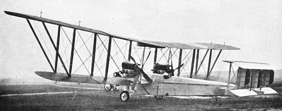
The first F.E.4 with two R.A.F. 5 engines.
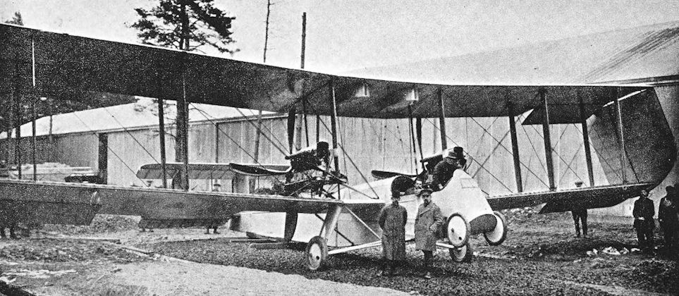
F.E.4 with wing extension folded down.
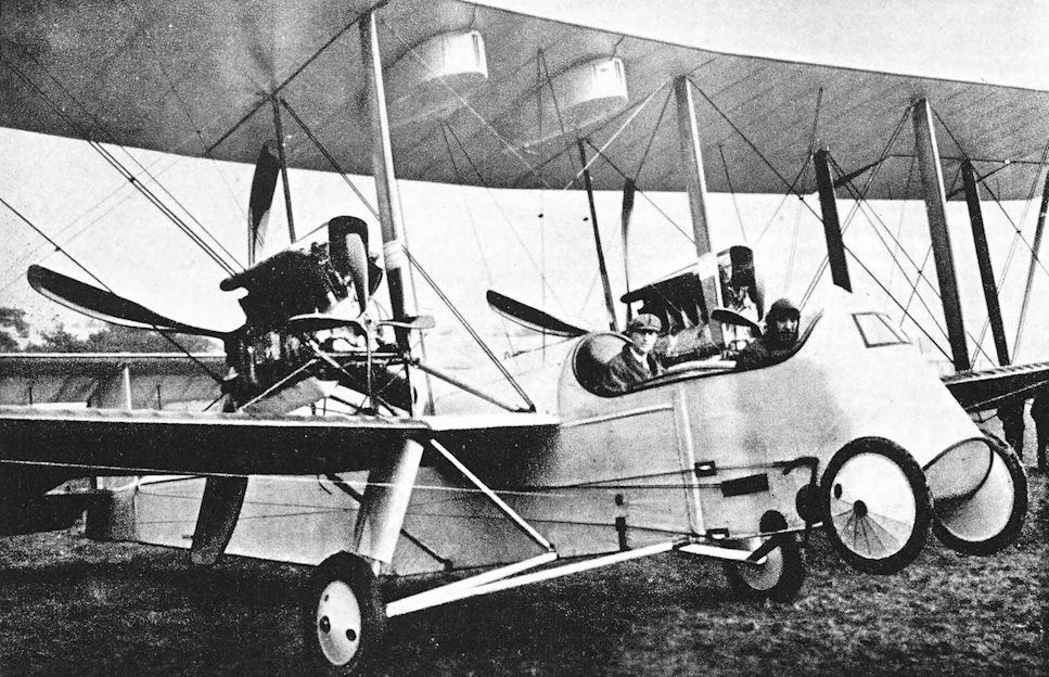
F.E.4. The installation of the R.A.F. 5 engines. The small airscrews which were fitted to assist cooling can be clearly seen.

Sometimes described as the F.E.4a, the second aircraft had two Rolls-Royce Eagle engines.
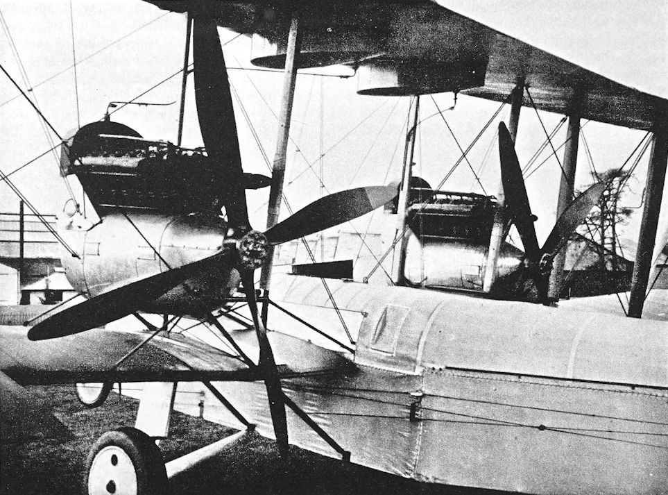
F.E.4. The installation of the Rolls-Royce engines.
R.E.8 and R.E.8a
THEY called it the Harry Tate. That was, of course, inevitable. Even if the R.E.8’s official designation had not lent itself so readily to that mutation, its quaint appearance was held by some to be vaguely suggestive of the music-hall mechanics so ably demonstrated by the great contemporary comedian.
The eighth R.E. owed nothing, either in construction or appearance, to its lineal predecessors. Regrettably, however, it retained the quality of inherent stability which, in the absence of any combat experience, had been postulated for reconnaissance aeroplanes in 1912. This is perhaps the more remarkable because the R.E.8 owed its existence to the realisation, in the autumn of 1915, that the B.E.2C was obsolete. At that time R.F.C. Headquarters in France sent home a statement, based on experience gained in action, of their requirements for a corps reconnaissance and artillery-spotting aeroplane. It was particularly requested that the new machine be capable of defending itself.
Work on the design of a two-seater to meet the terms of the specification was begun at the Royal Aircraft Factory early in 1916; the designation R.E.8 was given to the new machine. In construction it differed from the earlier R.E.s by having an all-wood fuselage. At their forward ends the longerons converged to form the engine bearers. With the aircraft in flying position the upper longerons sloped upwards towards the tail; this gave the fuselage a peculiar appearance which was accentuated by the backward tilt given to the 150 h.p. R.A.F.4a engine.
The basic fuselage structure was a typical wire-braced box girder, and had a rounded top-decking for part of its length. The pilot sat in the front cockpit, and a movable mounting was provided for the observer’s Lewis gun which, on the prototypes, was the only weapon carried.
In appearance the R.E.8 looked more like a close relative of the B.E.2e than a descendant of any preceding R.E. type. That it did so was due to its wing arrangement: the heavily staggered mainplanes were of unequal span, and the long extensions of the upper wings were braced by wires from kingposts above the interplane struts. Ailerons were fitted to upper and lower wings, and were linked by light struts and wires; the long upper ailerons were made in two parts. The wings had wooden spars and ribs, and were internally cross-braced by wire. Both the main and auxiliary flying wires of the single bracing bay were duplicated, and the extensions of the upper wings were braced against flying loads by Rafwires running from the lower ends of the interplane struts.
The tailplane was similar in shape to that of the B.E.2e and was adjustable; its incidence could be altered by means of a hand-wheel in the pilot’s cockpit. The R.E.8’s resemblance to the B.E.2e was somewhat diminished by its remarkably small fin and rudder assembly: the fin was of narrow chord, and the small surface under the fuselage was little more than a fairing for the tail-skid which, on the prototypes, was built into the base of the rudder. A prototype R.E.8 was in France, at No. 2 Aircraft Depot, Candas, in mid-July, 1916.
Initial estimates of the R.E.8’s performance fired the War Office with such enthusiasm that the machine was ordered virtually off the drawing-board, and large contracts were placed with several contractors. The aeroplane was unlucky from the start. Production was delayed for some time owing to shortages of some raw materials; when the first production machines appeared they were unduly prone to spin, and many fatal accidents occurred, both at home and overseas. Many of the crashes were doubtless attributable to the inexperience of sketchily-trained pilots, and some to the unreliability of the early production R.A.F. 4a engine. The unpleasantness of these accidents was increased by the readiness of the R.E.8 to burst into flames after striking the ground. The petrol tanks were directly behind the engine, which was usually driven back into them by the impact of the crash; the fuel then poured over the hot engine and fire was inevitable.
The R.E.8 at once acquired an evil reputation which was not improved by its appearance, for the long extensions of the upper wings reminded pilots of all they had heard about the behaviour of the B.E.2e’s wings. The production machines were fitted with a fixed Vickers gun for the pilot, mounted externally on the port side of the fuselage and synchronised by means of the Vickers mechanical gear. The first few R.E.8s had a rather crude form of rotating gun-mounting for the observer’s Lewis gun, but the Scarff ring-mounting was soon standardised.
The fin and rudder remained almost unchanged from those of the prototype; in fact, the only modification slightly reduced the size of the rudder, the lower end of which was taken up clear of the tail-skid. Investigations of the accidents showed that the area of the vertical tail surfaces was too small, and the area of the fin was thereafter progressively increased. At first the root chord of the upper fin was increased, but the small triangular under-fin remained unchanged. This proved to be insufficient, and a new under-fin of increased area was fitted. With this modification, the R.E.8’s tail unit assumed that characteristic outline which was one of its peculiarities, and was more or less standardised in this form. Ultimately, however, a very much larger upper-fin with a curved leading edge was fitted to some R.E.8s, and with it the aeroplane at last looked fairly safe.
The modifications were the outcome of investigations made at the behest of Lord Cowdray, then President of the Air Board, and were carried out under the direction of the deputy controller of the Technical Department. The theory of the time was that the original vertical tail was too small to counteract the torque reaction of the airscrew when the machine was climbing; consequently the swing developed unchecked until the rudder was drawn out of the slipstream and became dangerously ineffective.
After the second modification the R.E.8 became quite safe and manageable, and remained in service until the Armistice, when fifteen squadrons in France were still equipped with the type. Nevertheless, it was not a good aeroplane, either to fly or to fight. The R.E.8’s upswept fuselage had been designed to provide a large angle of attack when the aircraft was on the ground, in the hope that the braking effect of the wings would shorten the landing run and enable the machine to use small fields with safety. Despite this - or perhaps because of this - many pilots found the R.E.8 tricky to land until they were accustomed to it. In the three-point attitude the nose seemed absurdly high, an illusion which was heightened by the shape and position of the engine’s large air-scoop; consequently many pilots failed to appreciate the need for bringing the stick well back on landing, and overshooting of the landing area was not uncommon.
The Royal Aircraft Factory had failed to profit from the B.E.2c’s frequent demonstrations that inherent stability, however desirable it might have been in an aeroplane designed exclusively as an observation machine, was no asset to an aircraft which was required to defend itself when attacked. The R.E.8 incorporated some of the Factory’s latest ideas on stability. Consequently it lacked the manoeuvrability which was so vital in combat; more importantly, by the time it came into operational use its performance was no longer good enough. The official conception of the R.E.8’s performance was over-optimistic, and it was frequently called upon to attempt missions which were quite beyond its capabilities.
An early development of the R.E.8 appeared under the designation R.E.8a. Royal Aircraft Factory drawings of the R.E.8a dated October, 1916, depict an aircraft identical in all leading characteristics to the standard R.E.8 but powered by a 200 h.p. Hispano-Suiza engine with a flat frontal radiator of rectangular shape. In December, 1916, the R.E.8 numbered A.95 was converted into an R.E.8a, but unfortunately no photographs of the aircraft seem to have survived. The R.A.F. drawings show that the R.E.8a had a gravity tank under the root of the port upper mainplane, and the Vickers gun was mounted in much the same way as that of the S.E.5 - namely, on top of the fuselage, offset to port. The R.E.8a was not developed, doubtless because every available Hispano-Suiza engine was required for the S.E.5s which were then just going into production; and only the standard R.E.8 was built in quantity.
By the end of 1916, eighteen R.E.8s had been delivered to the R.F.C. in France. The first squadron to be equipped with the type was No. 52, which arrived in France on November 16th, 1916. This squadron suffered so many casualties in flying accidents attributed to the early R.E.8’s flying characteristics that the morale of the unit’s personnel was in danger of being affected. The R.E.8s were therefore withdrawn and were replaced by the B.E.2e’s which had formerly belonged to No. 34 Squadron. The B.E.2e’s were used by No. 52 Squadron for several months before R.E.8s were again issued to the unit. Meanwhile, other squadrons had been equipped with the type.
No. 21 Squadron received R.E.8s as replacements for its B.E.12s in February, 1917. On the 23rd of that month No. 59 Squadron arrived in France equipped throughout with R.E.8s; and No. 13 Squadron exchanged its B.Es for the new type in April, 1917. Thereafter more and more Corps squadrons were given R.E.8s, and the last to receive the type was No. 69 (Australian) Squadron, which took its R.E.8s to France on September 9th, 1917.
April 1917 was a black month for the Royal Flying Corps. During it the R.F.C. suffered more casualties than in any other month of the war: no fewer than 316 pilots and observers were lost. In many cases the reason for losses lay in obsolete aircraft; in others, trouble with new engines and equipment was the cause; but the casualties among the R.E.8s were attributable only to the ineffectiveness of the type as a military aeroplane.
On April 13th, 1917, six R.E.8s of No. 59 Squadron set out at 8.15 a.m. to obtain photographs of the Drocourt-Queant switch line. Only two of the machines had cameras; the other four were acting as escorts. Some reliance was placed on the presence of patrols of six F.E.2d’s, three Spads, and the Bristol Fighters of No. 48 Squadron. But the F.Es lost formation and two of their number, the Spads were late, and the Bristol Fighters saw nothing of the R.E.8s. None of No. 59 Squadron’s machines returned to their aerodrome at Bellevue, and ten of their pilots and observers were killed. The R.E.8s were attacked by six enemy single-seaters led by Manfred von Richthofen, and all were shot down within minutes. Just over a year later, however, the R.E.8 was to have its revenge against Richthofen.
Despite this early proof of its inferiority the R.E.8 was issued in increasing numbers to the Corps squadrons. Like the B.E.2C, 2d and 2e before it and the D.H.9 after it, the R.E.8 had been officially selected for large-scale production; and produced it duly was, for better or for worse. After it had been in service for some time, the pilots and observers grew to understand its few capabilities and its many limitations, and thereafter the enemy fighter pilots did not have things all their own way.
This proved to be the case on August 16th, 1917, during the Battle of Langemarck. An R.E.8 of No. 7 Squadron was attacked by two Albatros scouts when taking photographs over Poelcapelle. One enemy fighter was instantly shot down by the R.E.8 observer, and the other dived away. Later that afternoon, eight Albatros scouts attacked another of No. 7 Squadron’s machines. The observer fired a good burst of sixty rounds into one of the enemy machines at close range, and it went straight down to crash; all seven of the others retreated at once. An R.E.8 of No. 21 Squadron survived even greater odds that day, for it was attacked by nine Albatros scouts: the R.E.8 escaped after the observer shot down one of the enemy out of control.
Such fights, frequent as they were (though not always so successful), were incidental to the R.E.8’s principal duties of reconnaissance and artillery-spotting. Those who flew in France during the years 1917 and 1918 are not likely to forget the seemingly ever-present R.E.8, flying its stolid, elliptical course, and trailing a wake of anti-aircraft shell-bursts behind it. That it did much good work in this way is to the credit of the pilots and observers who flew it. The R.E.8 was given to them without choice of alternative: in it they did their duty.
During the Battle of Messines the R.E.8s of No. 21 Squadron enabled our artillery to master the German batteries. On June 7th, 1917, they were instrumental in bringing about the silencing of no fewer than seventy-two enemy batteries. Two months later, during the Battle of Ypres, No. 16 Squadron won distinction by its good work, not only in artillery-spotting, but in photographic and contact patrol work.
In September, 1917, the Corps squadrons of the I and III Brigades began to make night-bombing attacks which were calculated to assist in the main Ypres offensive. The R.E.8s and Armstrong Whitworth F.K.8s of these squadrons made their first night raids on the night of September 5th/6th, and later in the month made machine-gun attacks against road traffic by night. These night attacks continued well into 1918, and by April of that year night reconnaissances were being made in conjunction with the bombing attacks.
During the German offensive in March, 1918, the R.E.8s of the Corps squadrons carried bombs when they set out upon their normal duties of artillery cooperation, and added to the harassing of the enemy forces. The machines of No. 53 Squadron bombed and machine-gunned German troops along the front of the Fifth Army throughout the afternoon of March 21st.
On April 21st, 1918, two R.E.8s of No. 3 (Australian Flying Corps) Squadron were attacked by Richthofen’s squadron. Four Fokkers detached themselves from the main enemy formation to attack, but the R.E.8s put up a stout fight. Two of the enemy fighters quickly withdrew after being hit by the observers’ fire, and the British anti-aircraft gunners opened fire on the remainder of the enemy. The shell-bursts attracted the attention of Captain A. R. Brown, who was leading two flights of Camels of No. 209 Squadron.
The rest of the action is described in detail in the history of the Sopwith Camel. Richthofen was shot down and killed by Brown - and, as the fight drifted westwards, the Australian R.E.8s quietly returned to their job of photographing an area west of Hamel.
In July, 1918, the R.E.8s of No. 9 Squadron were used to drop supplies of ammunition by parachute to infantry in forward positions. Each machine carried two boxes containing 1,200 rounds of small-arms ammunition; and each box was attached to a cylinder containing a parachute. This technique was employed frequently thereafter, and during the great Allied advance of 1918 the Corps squadrons dropped from 30,000 to 60,000 rounds per day to British troops.
The R.E.8 served in other theatres of war. In Palestine, part of the equipment of No. 67 (Australian) Squadron in 1917 consisted ofR.E.8s; and in July, 1917, the War Office decided to raise an R.E.8 squadron, No. 113, in Egypt for service in Palestine. The latter unit was formed at Ismailia, and the first Flight arrived at Weli Sheikh Nuran on September 23rd, 1917. The squadron was up to full strength by October 10th, but less than half of its equipment consisted of the promised R.E.8s. On October 27th, No. 113 had five R.E.8s and eight B.E.2e’s, whilst No. 67 had five R.E.8s, five B.E.12a’s, seven B.E.2c’s and 2e’s, and one Martinsyde Elephant. A year later No. 113 Squadron had sixteen R.E.8s; by that time No. 14 Squadron had a similar number of the type, and the Jerusalem Flight of No. 142 Squadron had five.
To help the infantry during the great retreat of the Turks in September, 1918, the R.E.8s of No. 113 Squadron were employed to lay smoke screens. A special apparatus had been devised for the purpose in the Middle East; by its means sixty smoke candles could be dropped successively to create a screen 400 yards long. The device was successfully used twice on September 19th, 1918, but the rout of the Turkish forces rendered its further use unnecessary.
Parenthetically it should be recorded that this was not the first use of smoke screens laid by aircraft. On August 8th, 1918, the R.E.8s of Nos. 5, 9 and 3 (Australian) Squadrons laid a number of smoke screens during the Amiens offensive. This was done by dropping 40-lb phosphorus bombs, but the screens were limited and their renewal would have overtaxed any Corps squadron.
The defeat of the Turks in Palestine was effectively hastened by the R.E.8s of No. 113 Squadron on September 23rd, 1918. Sixteen aircraft dropped one hundred and twenty-two 20-lb bombs on the retreating enemy on the Es Salt-Amman road. A week later the machines of Nos. 14 and 113 Squadrons were used to carry urgently needed petrol and oil to El Affule aerodrome. The R.E.8s transported a total of 928 gallons of petrol and 156 gallons of oil.
The R.E.8 had a share in the Mesopotamian campaign. On August 13th, 1917, No. 63 Squadron arrived at Basra, and its first two R.E.8s arrived on September 14th and 16th; the remainder arrived during October. The first two R.E.8s were lost on their first reconnaissance flight over the Turkish lines. Over Tikrit they met a Halberstadt and at once dived to attack. On this occasion the extensions of the upper wing on one R.E.8 lived up to their reputation: they folded back and the machine crashed. At the same time the engine of the second R.E.8 failed, and the pilot was obliged to land.
No. 30 Squadron received its first R.E.8 on October 17th, 1917, and re-equipment continued throughout the autumn of that year. Squadrons Nos. 30 and 63 bore the brunt of the reconnaissance work of the Mesopotamian campaign, and at one time during 1918 the R.E.8s of No. 63 were averaging ten hours’ flying per day.
How a Davis gun came to be in Mesopotamia in 1918 is something of a mystery. Notwithstanding the fact that it was originally developed for the R.N.A.S., a gun of that type was installed in the rear cockpit of an R.E.8 of “A” Flight, No. 30 Squadron. The weapon was mounted to fire forwards and downwards through a hole in the floor of the observer’s cockpit, and the R.E.8 was then used for ground attack work.
In November, 1917, No. 34 Squadron was transferred from France to Italy as part of the British detachment which was sent there to help the Italians after the calamity of Caporetto. Shortly after No. 34 Squadron’s departure, No. 42 was also withdrawn from the Western Front and sent to Italy. No. 34 Squadron reached Milan on November 14th and had its R.E.8s assembled by the 17th, whilst No. 42 Squadron arrived at Istrana on December 7th and made its first operational flights two days later.
When the Italian offensive at the mouth of the Piave was launched on July 2nd, 1918, the Italians were short of aeroplanes and pilots. To help them, a few R.E.8s went daily to the aerodrome at Malcontenta, whence they flew under the orders of the Italians. The greater part of their work consisted of artillery cooperation, and for that purpose Italian observers were carried.
In August, 1918, a Flight of R.E.8s were dispatched to Archangel to reinforce the R.A.F. Contingent in North Russia.
The Belgian Flying Corps used the R.E.8 from 1917 onwards. Twenty-two were supplied to Belgium in that year and, like the B.E.2c’s which had preceded them, were modified to have the 180 h.p. Hispano-Suiza engine. A frontal radiator of circular shape was fitted, and the nose of the aircraft resembled that of contemporary Spad types; the cowling was liberally provided with louvres, and exhaust manifolds of unusual design were fitted. One of these Hispano-powered R.E.8s is still preserved in the Musee Royal de l’Armee et d’Histoire Militaire in Brussels.
The R.E.8 battled on until the Armistice. It was due for replacement by Bristol Fighters powered by the Sunbeam Arab engine, but the replacements never arrived. The original date set for the substitution of Bristols was April, 1918; but it was postponed until September because it was feared that a shortage of Sunbeam Arab engines would result.
Meanwhile, more detail modifications had been made. The original undercarriage, which had consisted of two vees of faired steel tubing, was replaced by a pair of wooden vee struts made of ash. The lower portion of the engine cowling was made deeper and larger, and was without the long blisters on its underside. The introduction of the very large main fin has already been mentioned. Some late production R.E.8s were fitted with Imber self-sealing fuel tanks.
For experimental purposes R.E.8s were used quite extensively, and figured in several investigations into control forces. Elevators of different areas were fitted and tested to determine what proportion of the horizontal area provided the most efficient elevator control.
It was intended to fit the Rolls-Royce Eagle engine to 75 Napier-built R.E.8s (numbered D.4811-D.4885), but confirmation that this was done is lacking.
The Royal Aircraft Factory began experimenting with superchargers as early as 1916, and by the beginning of 1917 sufficient data had been collected to enable an exhaust-driven turbo-compressor to be designed. It was learned, however, that Professor Rateau had built a similar supercharger in France, and that it had given promising results on the test bench. Arrangements were forthwith made for a Rateau compressor to be delivered to Farnborough, where it was fitted to a 200 h.p. R.A.F. 4d engine and installed in an R.E.8. The engine drove a four-bladed variable-pitch airscrew similar in general design to that which was tested on B.E.2C No. 4122. The fin and rudder of the experimental R.E.8 were enlarged, and the rudder was horn-balanced.
The first flight of this R.E.8 was made in March, 1918. It was found that the engine overheated, and a much larger air scoop was fitted above the cylinders; this scoop was enormous, and was used on all subsequent flights. The variable-pitch airscrew was used only once more, however, for there was too much slackness in its wholly mechanical control gear, and a specially designed two-bladed airscrew was substituted. This airscrew was used only once, and was replaced by the standard R.A.F. qd four-bladed airscrew.
The experiments terminated with the ninth flight of the supercharged R.E.8 on May 4th, 1918. Owing to a misunderstanding about the supercharger control settings, the turbine failed at 28,000 r.p.m. when the R.E.8 was at 13,700 feet, and was damaged beyond repair. An installation designed wholly at the R.A.E. envisaged a supercharged R.A.F. qe engine fitted to an R.E.8, but seems not to have been built.
After the Armistice the R.E.8 all but vanished from the Service scene. No. 6 Squadron took its R.E.8s with it when it was sent to Basra in the middle of 1919, but elsewhere the type did not long survive. A few were retained for the completion of experiments - for instance, there are indications that an experimental installation of an R.A.F. 5 engine was made in 1919 - but the great majority were withdrawn and scrapped. There was nobody to regret the passing of the Harry Tate, but it will always be remembered as one of the great workers of the war days; an aeroplane undistinguished in design or performance, yet one which, in the hands of courageous men, did much good though unspectacular work in spite of itself.
SPECIFICATION
Manufacturers: The Royal Aircraft Factory, Farnborough, Hants.
Other Contractors: The Austin Motor Co. (1914), Ltd., Northfield, Birmingham; The Coventry Ordnance Works, Ltd., Coventry; The Daimler Co., Ltd., Coventry; D. Napier & Son, Ltd., Acton, London, W.; The Siddeley-Deasy Motor Car Co., Ltd., Park Side, Coventry; The Standard Motor Co., Ltd., Cash’s Lane, Coventry.
Power: R.E.8 Standard: 150 h.p. R.A.F. 4a. Belgian R.E.8s: 180 h.p. Hispano-Suiza. Experimental: 200 h.p. R.A.F. 4d with Rateau supercharger; 150 h.p. R.A.F. 5. R.E.8a: 200 h.p. Hispano-Suiza.
Dimensions: Span: upper 42 ft 7 in., lower 32 ft 7 1/2 in. Length: R.E.8, 27 ft 10 1/2 in.; R.E.8a, 27 ft 7 in. Height: 11 ft 4 1/2 in. Chord: 5 ft 6 in. Gap: 5 ft 6 in. Stagger: 2 ft. Dihedral: 3 30'. Incidence: 4. Span of tail: 14 ft. Wheel track: 5 ft 9 in. Airscrew diameter: 9 ft 9 in.
Wings: 377-5 sq ft. Tailplane: 24 sq ft. Elevators: 22 sq ft. Fin: 5 sq ft. Rudder: 10 sq ft.
Weights {lb) and Performance:
Aircraft Prototype Production R.E.8 (R.A.F. 4a)
- Without bombs 2 X 112-lb bombs
No. of Trial Report - M.108B M.108B
Date of Trial Report July 21st, 1916 September, 1917 September, 1917
Type of airscrew used on trial - T.6296 T.6296
Weight empty 1,622 - 1,803
Military load 232 185 351
Crew 360 360 360
Fuel and oil 378 - 355
Weight loaded 2,592 2,678 2,869
Maximum speed (m.p.h.) at
1,600 ft 106-5 - -
5,000 ft - 103 -
6,500 ft - 102 98
9,910 ft 93 - -
10,000 ft - 96-5 92-5
11,400 ft 90 - -
13,700 ft 86 - -
m. s. m. s. m. s.
Climb to
1,000 ft 1 30 - - - -
2,000 ft 3 05 - - - -
3,000 ft 4 40 - - - -
4,000 ft 6 20 - - - -
5,000 ft 8 10 11 25 - -
6,000 ft 10 25 - - - -
6,500 ft - - 15 50 21 00
7,000 ft 13 00 - - - -
8,000 ft 15 40 - - - -
9,000 ft 18 30 - - - -
10,000 ft 22 00 29 05 39 50
11,000 ft 26 05 - - - -
12,000 ft 31 10 - - - -
13,000 ft 38 00 - - - -
13,200 ft 40 00 - - - -
Service ceiling (feet) 13,200 13,500 11,000
Endurance (hours) - 4 1/4 —
Tankage: Petrol: main gravity tank 37-5 gallons; service gravity tank 10-5 gallons; total 48 gallons. Oil: 3-5 gallons.
Armament: One fixed forward-firing Vickers machine-gun mounted on the port side of the fuselage, and synchronised to fire through the airscrew; one Lewis machine-gun on Scarff ring-mounting on rear cockpit. The bomb-load was usually two 112-lb bombs, four 65-pounders, or an equivalent weight of lighter bombs. The bomb racks were fitted under the lower wings.
Service Use: Western Front: R.F.C. Squadrons Nos. 4, 4(A), 5, 6, 7, 9, 12, 13, 15, 16, 21, 34, 42, 52, 53, 59, 69 (Australian) (later No. 3 Squadron, Australian Flying Corps), H.Q. Communication Squadron. No. 56 Squadron had one R.E.8. The type was also used by the Belgian Flying Corps. Italy: R.F.C. Squadrons Nos. 34 and 42. Palestine: R.F.C. Squadrons Nos. 14, 67 (Australian), 113, 142 (one Flight). Mesopotamia: R.F.C. Squadrons Nos. 30 and 63. Russia: R.A.F. Contingent at Archangel. Home Defence: No. 77 Squadron. Training: used at W/T Telegraphist School, Chattis Hill; School of Army Cooperation, Winchester; School of Photography, Maps and Reconnaissance, Farnborough; Air Observers’ Schools at Eastchurch, Manston and New Romney; Advanced Air Firing School, Lympne; No. 1 Training Depot Squadron, Stamford; No. 20 Training Squadron, Wye; No. 31 Training Squadron, Wyton; No. 35 Training Squadron, Northolt; No. 39 Training Squadron, Narborough; Training Squadron at Netheravon; Artillery Observation School, Almaza, Egypt.
Serial Numbers:
Serial Nos. Contractors Contract No.
7996-7997 Royal Aircraft Factory —
A.66-A.115 Royal Aircraft Factory —
A.3169-A.3268 Austin 87/A/488
A.3405-A.3504 Siddeley-Deasy 87/A/486
A.3506-A.3530 Royal Aircraft Factory —
A.3531-A.3680 Daimler —
A.3681-A.3830 Siddeley-Deasy 87/A/785
A.3832-A.3931 Napier 87/A/696
A.4161-A.4260 Daimler —
A.4261-A.4410 Austin 87/A/785
A.4411-A.4560 Standard 87/A/785
A.4564-A.4663 Standard 87/A/639
A.4664-A.4763 Coventry Ordnance Works 87/A/727
A.6801-A.7000 Allotted for R.E.8s to be built by the British & Colonial Aeroplane Co., Ltd., but contract cancelled and serial numbers re-allocated
B.836, B.845 Southern Aeroplane Repair Depot (Probably rebuilds)
B.2251-B.2300 Napier 87/A/696
B.3401-B.3450 Daimler -
B.5001-B.5150 Daimler A.S.7399
B.5851-B.5900 Austin 87/A/785
B.6451-B.6480 Siddeley-Deasy 87/A/785
B.6481-B.6624 Siddeley-Deasy A.S.7903
B.6631-B.6730 Coventry Ordnance Works A.S.8871
B.7681-B.7730 Siddeley-Deasy A.S.7903
C.2231-C.3030 Daimler A.S.7399
C.4551-C.4600 Napier 87/A/696
C.5026-C.5045 Coventry Ordnance Works 87/A/727
C.5046-C.5125 Coventry Ordnance Works A.s.8871
D.1501-D.1600 Standard A.S.32162
D.3836-D.3910 Napier -
D.4661-D.4810 Standard A.S. 32162
D.4811-D.4885 Napier (Rolls-Royce Eagle engine) A.S.28127
D.4886-D.4960 Napier A.S.35980
D.6701-D.6850 Coventry Ordnance Works A.S.27751
E.1-E.300 Siddeley-Deasy A.S.27757
E.1101-E.1150 Napier 35A/25/C.11
E.1151-E.1250 Siddeley-Deasy 35A/24/C.10
F.1553-F.1602 Siddeley-Deasy 35A/579/C.479
F.1665-F.1764 Standard 35A/625/C.504
F.3246-F.3345 Siddeley-Deasy 35A/1072/C.889
F.3548-F.3747 Daimler 35A/1073/C.900
Later batches were numbered about F.6016 and H.7042.
Production and Allocation: A total of 4,077 R.E.8s were built; of these, forty-five were constructed at the Royal Aircraft Factory. The squadrons with the Expeditionary Force received 2,157; the total number of R.E.8s sent to the Middle East was 327; 105 went to Italy; nineteen to Home Defence units; and 1,195 to training units. Twenty-two were delivered to Belgium. The R.A.F. had 1,913 R.E.8s on charge on October 31st, 1918: 674 in France, forty-nine in Italy, fifty-six en route to the Middle East, 127 in Egypt and Palestine, and fifty-three in Mesopotamia. At home, two were with Home Defence units, 167 at schools, fifty-nine at Aeroplane Repair Depots, 111 at Aircraft Acceptance Parks and with contractors, 282 in store, fifty-eight in Ireland, and 275 at various home stations.
Notes on Individual Machines: A.95: became R.E.8a. A.3475: No. 39 Training Squadron, Narborough; had the final large fin. A.3489: No. 52 Squadron. A.3561: became R.E.9. A.3652: “Victoria No. 1, Australia No. 19, ‘Sargood Bros.’"; A.3662: presented by Mr H. Teesdale Smith, Aircraft “J” of No. 3 Squadron, Australian Flying Corps. A.3747: “Australia No. 20, N.S.W. No. 18, ‘The McCaughey’.” A.3754: “Australia No. 21, N.S.W. No. 19, ‘The Narrandera Jerilderie’.” A.3792: “Malaya No. 32, ‘The A. N. Kenion’.” A.3902 : had the final large fin. A.4480: No. 16 Squadron, A.4537: No. 3 Training Squadron, Wyton. A.4600: became R.E.9. B.836: aircraft “15” of No. 15 Squadron. B.3412: No. 15 Squadron. B.5106: “I A”, No. 59 Squadron. C.2295: “Australia No. 23, N.S.W. No. 20, ‘The Tamworth and District’.” C.2298: “Australia No. 22, Queensland No. 1, ‘The North Queensland Residents’.” C.2441: had the final large fin. C.2670: “Punjab No. 25”. C.2982: “Malaya No. 1, ‘The Eu Tong Sen’.” D.4960: used in Russia, 1919. E.26: had the final large fin. E.254: “Marple”. E.256: “Lamberhurst”. F.3556: “A Paddy Bird from Ceylon”, preserved in the Imperial War Museum, London. F.6016: “Marjorie”, Aircraft “K” of No. 69 Squadron.
Costs:
Airframe without engine, instruments and guns £1,232
R.A.F. 4a engine £836
200 h.p. Hispano-Suiza engine £1,004
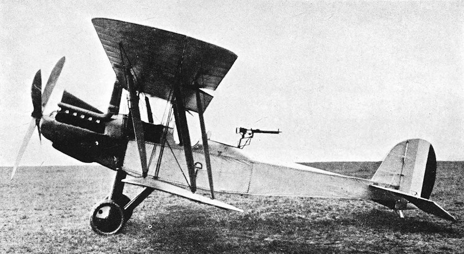
One of the two R.E.8 prototypes, either No 7996 or 7997. The aircraft was armed with a Lewis gun of the observer's cockpit, a feature that was criticised by the RFC when the type was first flown in France.
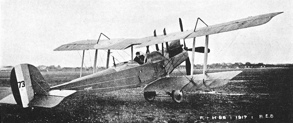
Early production R.E.8, serial number A.73, with pillar-type gun-mounting in rear cockpit.
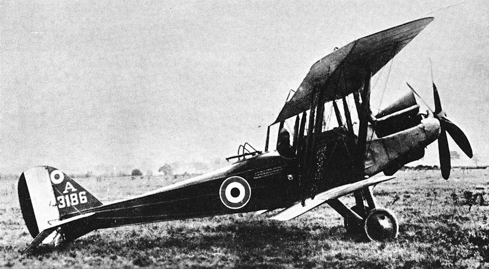
R.E.8 with enlarged main fin.
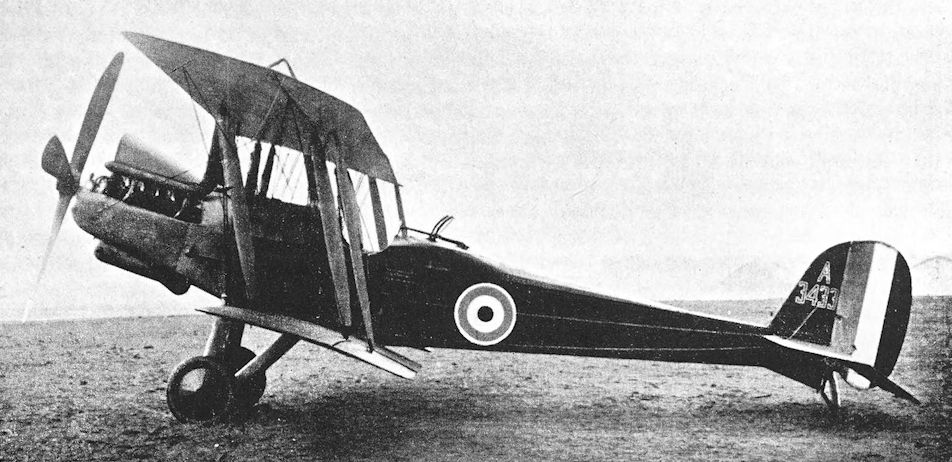
R.E.8 A3433 with 130 h.p. R.A.F. engine, built by the Siddeley Deasy Motor Car Company, with the initial small form of fin, the small sump cowling and Scarff ring for observer’s Lewis gun. This machine was still in use at the end of the war, as an artillery observation machine and as a night bomber.
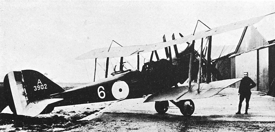
R.E.8 with the final very large main fin. This aircraft still has the early form of engine cowling.
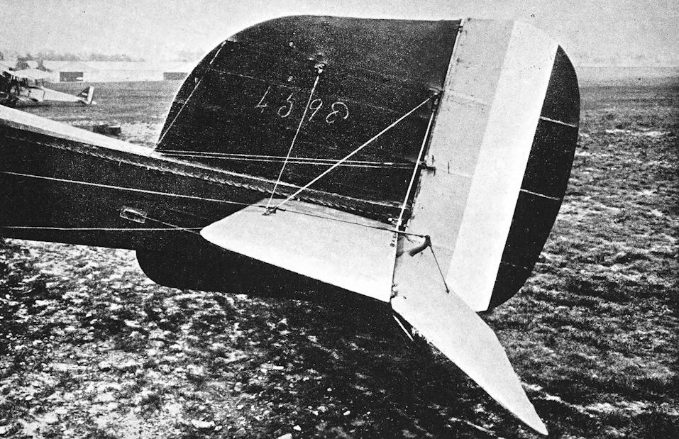
Experimental large fin fitted to R.E.8 number A.4598.
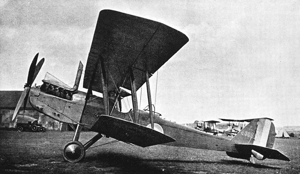
Standard R.E.8, serial number A.4683, with deep lower cowling under engine.
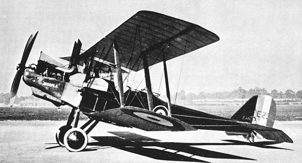
Standard production R.E.8, serial number E.254, with enlarged lower fin.
Siddeley Deasy built more than a thousand R.E.8 aircraft; E254 was one of them.
Siddeley Deasy built more than a thousand R.E.8 aircraft; E254 was one of them.
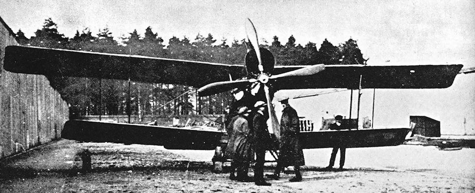
The R.E.8 with the supercharged R.A.F. 4d engine, enlarged air-scoop, and R.A.F. variable-pitch airscrew.
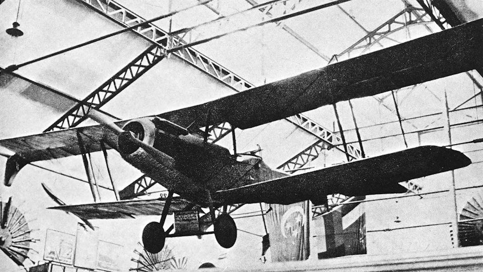
Belgian R.E.8 with Hispano-Suiza engine.
R.E.9
THE R.E.9 was a development of the R.E.8 which appeared in 1917. It had two-bay wings of equal span, and the wing-tips were of the characteristic blunt shape favoured by H. P. Folland. At least two R.E.8s, A.3561 and A.4600, were converted into R.E.9s, but it is uncertain which aircraft came first.
Of the photographs which have survived, those of A.4600 depict the R.E.9 in its true form with the 150 h.p. R.A.F. 4a engine in a standard R.E.8 installation. Doubtless control surfaces underwent modification from time to time, but it will be seen that A.4600 had a horn-balanced rudder, a large fin with straight leading edge, an under-fin reminiscent of that of the S.E.5, and long ailerons which were hinged to false spars a short distance behind the rear main spars of the mainplanes.
The wing area of the R.E.9 was very little greater than that of the R.E.8, and the later design may have been built to provide comparative data for wings of equal and unequal span on the same type of aircraft. Alternatively, it may have been an attempt to produce an aircraft with flight characteristics similar to those of the R.E.8 but with a stronger wing truss. However, the available performance figures for the R.E.g with R.A.F. 4a engine indicate that it was inferior to the R.E.8 in rate of climb at least, and that may be why the design was not developed.
The other R.E.9, A.3561, was flown in 1918 with a 265 h.p. Sunbeam Maori engine. That particular type of engine had been supplied almost exclusively to the Admiralty, and the installation of a specimen in an R.E.9 was probably made solely to determine the power-unit’s capabilities. The Maori was enclosed in a bulky cowling surmounted by a substantial central exhaust stack. Forward view from the cockpit was poor, and it was further impaired by the two radiator blocks. A gravity fuel tank was fitted above the centre-section.
The ailerons of A.3561 were of slightly shorter span than those of A.4600 and had only single control horns. The centre-section bracing was reinforced by the fitting of a diagonal strut between the normal struts on each side, and the fin had a rounded leading edge. There were large cut-outs in the roots of the lower mainplanes to improve the pilot’s downward view.
As first flown by Captain J. Palethorpe in May, 1918, the Maori-powered R.E.9 was catastrophically tail-heavy with engine on and nose-heavy with engine off. But for the presence of mind of Lieutenant W. H. S. Elliott, the flight observer, the machine would probably have crashed. Engine on, he hung shot bags (carried as ballast) round Palethorpe’s neck; engine off, he crawled as far aft as he could down the fuselage, taking the shot bags with him. His prompt action brought the R.E.9 to a condition in which it was just controllable.
In 1919 an R.E. 9 was used in a series of tests to determine the maximum amount of control which could be obtained with elevators of different areas. Four different elevators were fitted successively: they were respectively of 30, 35, 40 and 50 per cent of the total horizontal tail-area, and it was proved that the machine was most manageable with the 35 per cent elevators. For these experiments a sliding weight was installed in the R.E.9. This weight could be moved in flight from the observer’s cockpit to the tail. With the weight fully aft, the aircraft’s centre of gravity was in the correct position; but when it was fully forward the machine became very nose-heavy. The complete sequence of tests were performed by one pilot, Captain J. G. S. Candy; but the R.E.9 was flown with the 35 per cent elevators by Lieutenant R. K. Muir and Captain H. A. Renwick.
SPECIFICATION
Manufacturers: The R.E.9s were converted from R.E.8s built by the Daimler Co., Ltd. (A.3561), and the Standard Motor Co., Ltd. (A.4600).
Power: 150 h.p. R.A.F. 4a. A.3561 was modified to have the 265 h.p. Sunbeam Maori, engine No. 19379. Dimensions: Span: 38 ft 6 in. Length: 27 ft 7 in. Height: 10 ft 5 in. Chord: 5 ft 6 in. Gap: 5 ft 5 in.
Areas: Wings: 382 sq ft.
Weights: Loaded: 2,800 lb.
Performance: (With R.A.F. 4a) Climb to 5,000 ft: 11 min 20 sec; to 10,000 ft: 35 min 40 sec. Ceiling: 13,000 ft. (With Maori on flight dated August 6th, 1918) Climb to 2,500 ft: 2 min 30 sec; to 5,000 ft: 6 min 45 sec; to 6,000 ft: 8 min 30 sec; to 7,000 ft: 10 min 15 sec.
Armament: The R.E.9 could be armed in the same way as the R.E.8.
Serial Numbers: A.3561, A.4600.

R.E.9, A.4600 with R.A.F. 4a engine.

R.E.9, serial number A.3561, fitted with Sunbeam Maori engine.
S.E.5 and 5a
IN the year 1915 there appeared a new French aero-engine, designed by M. Marc Birkigt and made by the Hispano-Suiza company. It was an eight-cylinder water-cooled vee unit with each bank of cylinders cast in aluminium as a one-piece block; it delivered 150 h.p. for a weight of only 445 lb.
In the summer of 1915, one of these engines was inspected in Paris by Lieutenant-Colonel H. R. M. Brooke-Popham. On his recommendation, a British order for fifty engines was placed in August 1915, and negotiations were begun for the manufacture of the Hispano-Suiza in Britain. These negotiations involved the parent Hispano-Suiza company in Barcelona as well as the French firms who were manufacturing the engine under contract, and cost a great deal of time. British production of the Hispano-Suiza did not begin until the spring of 1916.
With the promise of this compact and workmanlike engine being available, the design staff at Farnborough began work on the design of a new single-seat fighter which was given the designation S.E.5. Their aim was to produce an aeroplane which could be flown with reasonable safety by pilots who had had only the sketchy flying training of the period. This presupposed a certain degree of inherent stability, and the design was revised after early wind-tunnel tests had shown that the original conception would not have been sufficiently stable.
The design work was largely done by H. P. Folland, assisted by J. Kenworthy and Major Frank W. Goodden. Much of the later success of the S.E.5 is attributable to careful designing, particularly in the matter of detail design, at which Mr Folland excelled.
The machine’s basic structure was typical of the war period. The fuselage was a wire-braced box girder composed of wooden longerons and spacers: plywood was applied to the fuselage sides below the engine bearers, and extended as far aft as the front spar of the lower mainplanes. A flat car-type radiator was mounted at the nose, and the short exhaust manifolds had a single central outlet. The main fuel tank was mounted on top of the upper longerons behind the engine; the tank was shaped to the contour of the fuselage top-decking. On the prototype S.E.5 the tank was covered by an extension of the engine cowling, but it was left uncowled in production machines. There was a gravity tank mounted externally above the centre-section well out to port. The undercarriage was a simple structure consisting of two steel tube vees.
The wings had spruce spars and were braced internally by wire. There were no conventional compression struts: in their place were certain ribs which were made solid. The single-bay interplane bracing was supplemented by two auxiliary mid-bay flying wires on each side. The incidence of the tailplane could be varied in flight; and a rather unusual feature was the location of the elevator cable runs within the fuselage and tailplane. The vertical tail assembly was a characteristic structure of highly practical design.
The fifty Hispano-Suiza engines which had been ordered in 1915 were delivered between August and December, 1916. One of the first was installed in the prototype S.E.5, A.4561, which first flew in December, 1916. This machine was later flown with modified exhausts and side extensions of the windscreen. In its first flights the S.E.5 gave every indication of being a satisfactory aircraft, but structural failure of the wings brought about the destruction of the prototype at the end of January, 1917. In the crash Frank Goodden lost his life, a life which could ill be spared from Britain’s aeronautical effort of the time.
Production had already been initiated, but was suspended while the crash was investigated. The shape of the wing-tip was re-designed to be much less sharply raked, modified strut-to-spar joints were fitted, and stronger lift-bracing was introduced. Construction of the first production batch of S.E.5s was too far advanced for the new wing-tip shape to be used, but the rear spars were reinforced and the other modifications incorporated. The machines of the second batch of S.E.5s had the modified wings of reduced span which became standard on all subsequent S.E.5s and 5a’s. Some machines were fitted with an improved gravity tank which was mounted within the leading edge of the upper centre-section; this arrangement also became standard.
The modifications proved to be entirely satisfactory, and in service the S.E.5 airframe gained a reputation for great structural strength which inspired confidence in combat.
The armament fitted to the production machines consisted of two machine-guns. A Vickers gun was mounted in front of the cockpit on the port side and with its breech mechanism enclosed within the top decking; and a Lewis gun was carried above the centre-section on a Foster mounting. The latter weapon could slide back along a curved rail until it was nearly vertical; in this position it could be reloaded and could also be fired upwards. It has been said that the Lewis gun was fitted to the S.E.5 in this way because Captain Albert Ball, V.C., had scored several successes with the Foster-mounted Lewis on his Nieuport Scout, and had exploited its ability to fire upwards.
The Vickers gun on the S.E.5 was synchronised to fire through the revolving airscrew by means of the Constantinesco hydraulic synchronising gear. This gun-gear gave a good deal of trouble before it became understood. Frequently the Vickers gun would not fire at all or, if it did, an S.E. pilot might find that he had shot his own airscrew off. Major J. T. B. McCudden experienced these troubles, despite meticulous personal attention to his guns. Describing his combat experiences at a time as late as September, 1917, he wrote: “My word! You cannot realise what it is to get on the Huns’ tails time after time, and then have your guns let you down.”
The first production S.E.5s were completed in March, 1917, and were delivered to No. 56 Squadron. That unit had been formed at Gosport in June, 1916, from a nucleus provided by No. 28 Squadron, and moved to London Colney during the following month. Major R. G. Blomfield assumed command early in February, 1917, and on the 26th of that month Captain Albert Ball was posted to the squadron as a Flight Commander. No. 56 Squadron received its first S.E.5 on March 13th, 1917, and by April 5th its establishment of the new machines was complete. On that date an advance party went to France, and two days later the complete squadron arrived at Vert Galand aerodrome.
In one or two features the early production S.E.5 was not satisfactory for operational use, and Major Blomfield kept his squadron grounded for two weeks to allow some essential modifications to be made. The machines delivered to No. 56 Squadron had a cumbersome transparent windshield which extended forward over the breech of the Vickers gun. It may have been hoped that this “greenhouse” (as it was called by the pilots) would facilitate the clearing of gun stoppages; but all it did was to interfere seriously with the pilot’s forward view, and it could have been a danger in a crash. Major Blomfield had the greenhouses replaced by a small flat Triplex windscreen which was adopted as a standard fitting on all S.E.5s.
Experience showed that it was better to have the fire of the Lewis gun converging with that of the Vickers at about 50 yards range instead of being parallel to it. The Foster mounting was therefore raised slightly at the rear end.
The S.E.5s of No. 56 Squadron made their first patrol on April 22nd, 1917, when five machines led by Ball patrolled between Lievin and Croisilles. An Albatros two-seater which they pursued escaped destruction only because strict orders had been issued that no S.E.5 was to cross the lines in any circumstances.
Captain Ball scored his first victory on an S.E.5 on April 23rd, when he shot down a green Albatros scout in flames from 13,000 feet over Cambrai. Ball did not at first like the S.E.5, for it was less responsive than the sensitive Nieuport Scout which he had been flying. His dislike of the S.E. was so great that he asked for, and obtained, a Nieuport for his personal use in No. 56 Squadron. However, after being saved from death on April 26 th, 1917, by the speed and double fire-power of the S.E.5, realised its true worth and used his Nieuport only once more over the lines.
Convincing proof of the S.E.5’s great structural strength was provided on April 28th, 1917. Lieutenant G. C. Maxwell had engaged a group of Albatros scouts over Fontaine when his machine was struck by anti-aircraft fire. His engine was damaged and his elevator controls rendered almost totally ineffective. With little control over his S.E., Maxwell glided down and hit the ground near Combles at about 140 m.h.p. The engine and its bearers broke off, but the remainder of the aircraft bounced on for nearly a hundred yards and was completely wrecked. Maxwell was quite uninjured.
In S.E.5 airframes various experimental versions of the 150 h.p. Hispano-Suiza engine were flown. In September, 1917, engines with compression ratios increased to 5-3 to 1 and 5-6 to 1 were fitted; the latter engine developed 192 h.p. Finally, in December, 1917, a Wolseley Viper engine was tested in an S.E.5. According to the official records of the performance trials, all these installations were made in S.E.5s with the long-span wings.
The Hispano-Suiza engine underwent development during 1916, and a geared version was produced which developed 200 h.p. The second S.E.5 prototype was fitted with one of these engines. This first installation was very similar to that of the 150 h.p. Hispano-Suiza, and could be distinguished only by its higher thrust-line and left-hand airscrew. The aeroplane itself had the original form of S.E.5 wings with reinforced rear spars. The third prototype, A.4563, was also fitted with the 200 h.p. Hispano-Suiza, but the radiator was provided with shutters and a four-bladed airscrew was used. The shorter-span wings were fitted, and the exhausts were the L-shaped manifolds which had been used on most of the first production S.E.5s. This aircraft was used operationally in France by Squadrons Nos. 56 and 84.
This modified version of the aircraft was designated S.E.5a, and all subsequent machines were of this type. The first production S.E.5a was delivered to No. 56 Squadron in June, 1917, and thereafter the type gradually replaced the S.E.5. No. 56 Squadron was completely re-equipped with the new type by August, 1917. The S.E.5a fuselage forward of the cockpit was a little deeper than that of the S.E.5, and long horizontal exhaust pipes were standard fittings. In No. 56 Squadron these long pipes were not liked at first; they were cut off just behind the rear exhaust stub and replaced by short pipes welded on at an outwards angle. Later, however, the long pipes were again used.
Unfortunately, the 200 h.p. Hispano-Suiza engine was dogged by ill-luck; consequently the S.E.5a was not so immediately effective as it might have been. Really large-scale production was still some way off, owing to difficulties in obtaining engines. At the insistence of the Admiralty, the Air Board had ordered 8,000 Hispano-Suiza engines in November, 1916, principally from the Mayen concern in France. This firm built a large factory for the purpose, using some £2 million advanced by the British Government, but the first engines did not come off the lines until late in 1917.
Meanwhile, production of the 200 h.p. engine was undertaken in England by the Wolseley company; and other Hispano-Suiza engines made in France by Brasier were fitted to S.E.5a’s.
The Wolseley-built engines were not at first successful. On May 7th, 1917, Sir William Weir, the Controller of Aeronautical Supplies, had to report that a 200 h.p. Hispano-Suiza engine made by Wolseley had broken four successive crankshafts after an average run of only four hours. Trials of this engine continued, and production went ahead after eleven modifications had been introduced, but the delay led to a reduction in output. As a stop-gap, the Wolseley concern were asked to make 400 Hispano-Suiza engines of the original 150 h.p. direct-drive version, an order which was later increased to 1,100. However, it was apparently not made clear to the contractors that they were required to produce the existing type, for they set about developing from the 150 h.p. Hispano-Suiza a high-compression engine of the same nominal power. The new engine became known as the Wolseley Viper, but the time spent on its design seriously retarded production by the company and did nothing to alleviate the immediate shortage of Hispano- Suiza engines: whereas it had been expected that 140 of these engines would have been delivered by the end of August, 1917, only ten had been completed.
This serious situation was further aggravated by the unreliability of the first 200 h.p. Hispano-Suiza engines delivered from the French firm of Brasier. Failures were frequent, and the engines had to be sent to the Clement Talbot works for overhaul. One of the most serious defects lay in the faulty hardening of the gearwheels and airscrew shaft; these had to be replaced by British-made spares. By October, 1917, however, the shortage of engines had become so acute that some of the French Hispanos were passed into service with the original unevenly hardened gears. The engines were accepted by the Aeronautical Inspection Directorate only on direct written instructions; and cautionary entries in the engine log-books warned that the faulty gearwheels had been fitted for lack of others, and that the running of the engine should be carefully watched. In extenuation of this indefensible action it was pleaded that defective engines were better than none at all.
These failures hit the S.E.5a particularly hard, and by January, 1918, no fewer than 400 new S.E.5 were held up in stores because no engines were available for them. The set-back could hardly have occurred at a more unfortunate time, for airframe production had expanded greatly during the last quarter of 1917: during the period 604 S.E.s were produced, whereas only 157 had been built during the preceding three months.
When in service, the machines with the defective engines were bad for morale: no pilot could be reasonably expected to have confidence in a machine of known unreliability.
Fortunately, the Admiralty’s foresight in 1916 saved the situation, which had become ugly indeed; for in the early months of 1918 the first deliveries of Mayen-built Hispano-Suizas were made against the order for 8,000 engines.
In action, the S.E.5a was an excellent fighting aircraft, and its finest testimonial lies in the fact that it was the mount of the leading British fighter pilots of the war. Major Edward (“Mick”) Mannock, V.C., S.O., M.C., scored more than 50 of his 73 confirmed victories while flying an S.E.5a, and the type was also flown with signal success by such pilots as Bishop, McCudden, Beauchamp-Proctor, McElroy and Rhys-Davids. The S.E., though it had none of the hair-trigger sensitivity of its great contemporary, the Sopwith Camel, was usefully manoeuvrable and yet stable enough to facilitate accurate shooting. Its reputation for strength was an enormous asset in combat, for if it lacked anything in manoeuvrability that small deficiency was more than outweighed by the liberties which could be taken without fear of structural failure.
S.E.5a’s became available in increasing numbers throughout the summer of 1917, and were issued to several squadrons. Despite trouble with the engines and Constantinesco gun-gear the aircraft gave a good account of itself. On September 28th, 1917, Captain J. T. B. McCudden of No. 56 Squadron led his patrol of S.E.5a’s to attack a group of Albatros scouts over Boesinghe, and destroyed five of the enemy without loss to the British machines.
McCudden had several S.E.5a’s while he was with No. 56 Squadron. The first was B.519, and was followed by A.4863 which gave him a great deal of trouble, particularly with its Constantinesco gear. In October, 1917, he took over the Martinsyde-built S.E.5a B.35, after another pilot had discovered the strength of the S.E.’s construction by flying McCudden’s previous machine through the side of a house: the pilot concerned was unhurt. On December 3rd McCudden received B.4891, an S.E.5a built by the Royal Aircraft Factory.
This machine had a smaller fin than was standard, and narrow-chord elevators were fitted. It was one of the first S.E.5a’s to have the improved undercarriage with the strengthened forward leg in each vee. For a time B.4891 wore the spinner of an L.V.G. C.V. that McCudden had shot down on November 30th, 1917: this spinner was painted red, and added 3 m.p.h. to the speed of the S.E.5a.
McCudden took the keenest personal interest in his S.E., and it was largely due to careful tuning that he was able to reach 20,000 feet in it, whereas the average Service S.E. could seldom exceed 17,000 feet.
In January, 1918, he had a specially modified Hispano-Suiza engine installed. It had special high-compression pistons, and greatly improved the S.E.’s rate of climb.
In squadron service the S.E.5a underwent various detail modifications to meet the personal requirements of pilots. Some machines were given extra bracing wires to the fin or mainplanes; some S.E.5a’s of No. 24 Squadron were rigged with reduced dihedral in order to increase manoeuvrability; and, most commonly, many machines had the streamlined headrest removed by pilots who wanted the best possible rearwards view.
The strengthened undercarriage, mentioned above, was introduced late in 1917. The forward leg of each vee, which on earlier S.E.s had been a single steel tube of streamline section, was a built-up component consisting of two steel tubes in the form of a long slender inverted V: the axle lay at the open end of this leg, between the two steel tubes. The double leg was faired over with plywood or sheet metal.
As more powerful Hispano-Suiza engines became available they were installed in S.E5a’s. The 220 h.p. and 240 h.p. geared Hispano-Suiza were fitted to some machines; and finally the Wolseley W.4A Viper was standardised for the type. The Viper was a high-compression development of the Hispano-Suiza engine; it was a direct-drive engine and reverted to having a right-hand airscrew. As has already been stated, a Viper was fitted to an S.E.5 airframe in December, 1917.
The Viper installation in the S.E.5a was of distinctive appearance, for the nose of the aircraft looked bulkier than with the Hispano-Suiza, and was generally less well streamlined. The sides of the radiator housing were quite flat, and short horizontal shutters were fitted to the radiator itself. Most Viper S.E.s dispensed with fairings at the ends of the valve rocker housings of the engine.
A few S.E.5a’s were fitted with the Wolseley W.4B Adder, an engine of the same nominal power as the Viper but with reduction gearing to the airscrew shaft.
During the German offensive of March, 1918, much ground attack work was performed by the scout squadrons of the R.F.C. The S.E.5a’s of Nos. 24 and 84 Squadrons did a considerable amount of this hazardous low-flying duty, and added low-level bombing to their repertoire; each S.E. carried four 25-lb Cooper bombs in racks under the fuselage. In the afternoon of March 22nd, 1918, twelve S.E.5a’s of No. 84 Squadron dropped forty-five bombs on enemy troops and transport near Holnon and scored many direct hits. The work of No. 24 Squadron between February and November, 1918, can be assessed from the facts that their S.E.5a’s dropped 2,229 bombs and fired 92,522 rounds at ground targets.
And so the S.E.5a flew and fought on until victory came in November. Several of the best German fighting pilots fell in combat with S.E.s, among them Werner Voss, Kurt Wusthoff and Erich Loewenhardt. It was an aeroplane whose fighting qualities were recognised and respected by the enemy.
The S.E.5 had an early introduction to Home Defence duties. On June 13th, 1917, the first enemy daylight attack on London was made, with heavy loss of life. So great was public indignation over this attack that the Government instructed Sir Douglas Haig to send one fighting squadron home from France and one to Calais. No. 56 Squadron flew its S.E.5s to Bekesbourne on June 21st and remained there until July 5th, when it returned to France after having seen no enemy aircraft at all.
S.E.5a’s were issued to Home Defence squadrons, but were not regarded as completely suitable for this class of work. They were satisfactory once they were in the air, but the water-cooled engine took much longer to warm up than did contemporary rotary engines, and quick take-offs were not possible. The S.E.5a was also said to be difficult to land on small aerodromes at night. The four Home Defence squadrons which had the type had all been re-equipped with Sopwith Camels by the time of the Armistice.
The S.E. served on other fronts in small numbers, for it was only with reluctance that the War Office permitted the dispatch of up-to-date aircraft to the less spectacular theatres of war. The Germans did not make the same mistake.
In September, 1917, Lieutenant-General G. F. Milne, then in command of the British forces in Macedonia, wrote to the War Office and pressed for more aircraft to be placed at his disposal. On October 12th the War Office sanctioned an increase in the establishment of Squadrons Nos. 17 and 47, and stated that nine S.E.5a’s had been allocated. The first S.E. arrived early in November, 1917, and by the following February each squadron had four. These machines had an immediately beneficial effect, and Captain F. G. Saunders and Lieutenant G. E. Gibbs of No. 17 Squadron made excellent use of their new mounts. On April 26th, 1918, the S.E.5a’s of Squadrons Nos. 17 and 47 were handed over to No. 150 Squadron, a new fighting squadron which had been formed on April 1st.
A few S.E.5a’s were used in Mesopotamia by “A” Flight of No. 72 Squadron, which had arrived at Basra on March 2nd, 1918.
For the Palestine campaign, General Sir Edmund Allenby asked for a fighting squadron, composed of one Flight of S.E.5a’s and two of Bristol Fighters, on October 27th, 1917. This request was refused at the time, but in January, 1918, No. 111 Squadron was equipped with S.E.s; and by the time Allenby launched his final offensive on September 19th, No. 145 Squadron was also in the field with six S.E.5a’s. The S.E.s of these two squadrons maintained standing patrols over the enemy aerodrome at Jenin, and kept the German pilots grounded. On September 21st, these S.E5a’s took part in the annihilation of the Turkish Seventh Army in the Wadi el Far‘a; two days later the machines of No. 111 Squadron made similar attacks on the Turkish Fourth Army on the Es Salt-'Amman road.
For training purposes some S.E.5a’s were converted into two-seaters. A second cockpit was cut out in front of the normal one. It has been said, however, that the flying characteristics were badly impaired and that the two-seat S.E.5a would spin at the slightest provocation.
Some S.E.5a’s were used for experimental purposes, both during and after the war. At least one S.E. was fitted with an underslung radiator in place of the usual frontal surface, and the nose was covered in by a blunt cowling. The engine appeared to be a Wolseley Viper, and the radiator apparently consisted of two Viper-type radiator blocks laid on their sides and mounted one above the other to form a single radiator.
At Martlesham Heath the Viper-powered S.E.5a E.5923 was fitted with an experimental tail unit. The fin and rudder were elliptical and somewhat similar to the vertical tail assembly of the German D.F.W. C.V; whilst the tailplane was tapered and sharply swept-back. The tailplane was in two parts: the forward portion was fixed, but the rear portion could be adjusted from the cockpit to provide longitudinal trimming. For spinning experiments another S.E.5a was fitted with a balanced rudder generally similar to that of the Avro 504, and had two small fins on the tailplane.
B.600 was rigged with no dihedral for experiments in manoeuvrability conducted at the R.A.E. just after the war; and C.1091 was fitted with the Royal Aircraft Factory variable-pitch airscrew. Other experiments were conducted to investigate exhaust manifold temperatures, and one S.E.5a was fitted with large finned pipes of cast aluminium for this purpose.
In the field of flight safety, the S.E.5a was used to test automatic landing apparatus and fire-extinguishing equipment. In 1919 one was fitted with a Palethorpe Skid, and in the following year a different type of ground proximity equipment was tested. Major G. H. Norman was responsible for the installation of a French fire-prevention apparatus in an S.E.5a in 1921: this was almost certainly E.5927. To put this equipment to the fullest test, Norman set fire to his machine in the air. The extinguisher put the fire out, but smoke blinded Norman on the approach and he crashed. His injuries later proved to be fatal.
Some S.E5a’s remained in service after the war, but the type was soon withdrawn. Australia and Canada used the type, and one Viper-engined S.E.5a was taken to Japan in 1921 by the British Aviation Mission to the Imperial Japanese Navy.
The S.E. was in service in America in small numbers after the war. It had been intended to mass-produce the type there, and a contract for 1,000 was given to the Curtiss company; the American-built S.E5a’s were to have the 180 h.p. Wright-Martin Hispano-Suiza engine. The Armistice was signed before production was properly under way, and only one all-Curtiss S.E.5a was completed; but fifty-six others were assembled from components sent over from Britain. In Britain itself, the American Expeditionary Force bought thirty-eight S.E5a’s in October, 1918.
A version known as the S.E.5E appeared in America in 1922-23. Fifty were built from spare parts, and the suffix letter indicated the name of the constructor, namely, Eberhardt. The S.E.5E had a plywood-covered fuselage and the 180 h.p. Wright-Hispano E engine.
It was perhaps appropriate that the years of peace should provide no lasting service use for the S.E.5a, for it was essentially a machine of the war and one of the greatest of its day.
SPECIFICATION
Manufacturers: The Royal Aircraft Factory, Farnborough, Hants.
Other Contractors: The Austin Motor Co. (1914), Ltd., Northfield, Birmingham; The Air Navigation Co., Ltd., Addlestone, Surrey; Martinsyde, Ltd., Brooklands, Byfleet;Vickers, Ltd. (Aviation Department), Imperial Court, Basil Street, Knightsbridge, London, S.W. (Factories at Crayford and Weybridge); Wolseley Motors, Ltd., Adderley Park, Birmingham.
Power: S.E.5: Standard, 150 h.p. Hispano-Suiza. Experimental, 150 h.p. Hispano-Suiza engines with compression ratios of 5-3 to 1 and 5-6 to 1, and 200 h.p. Wolseley W.4A Viper. S.E.5a: 200 h.p. Hispano-Suiza; 220 h.p. Hispano-Suiza; 240 h.p. Hispano-Suiza; 200 h.p. Wolseley W.4A Viper; 200 h.p. Wolseley W.4B Adder.
Dimensions: Span: S.E.5 prototypes and early production S.E.5s, 28 ft; S.E.5 and S.E.5a, 26 ft 7 1/2 in. Length: S.E.5, 21 ft 4 in.; S.E.5a, 20 ft 11 in. Height: S.E.5, 9 ft 5 in.; S.E.5a, 9 ft 6 in. Chord: 5 ft. Gap: 4 ft 7 in. Stagger: 1 ft 6 in. Dihedral: 5. Incidence: 5. Span of tail: 11 ft. Wheel track: 5 ft.
Areas: Wings: S.E.5 prototypes and early production, 249 sq ft; S.E.5 and S.E.5a, 244 sq ft. Ailerons: each 7-55 sq ft, total 30-2 sq ft. Tailplane: 15 sq ft. Elevators: 15-5 sq ft. Fin: 6-1 sq ft. Rudder: 5-9 sq ft. (On E.5923, modified at Martlesham, tailplane area was 16 sq ft, elevators 10-2 sq ft, fin 5-4 sq ft and rudder 5-2 sq ft.)
Tankage: Petrol: 35 gallons. Oil: 3 1/2 gallons.
Armament: One fixed Vickers machine-gun mounted on top of fuselage to port of centre, synchronised by Constantinesco gear to fire forward through the revolving airscrew; one Lewis machine-gun on Foster mounting above the upper centre-section, fired by Bowden cable. Four hundred rounds for Vickers gun; four 97-round drums for Lewis. Four 25-lb Cooper bombs could be carried on external racks under the fuselage.
Service Use: Western Front: S.E.5: R.F.C. Squadrons Nos. 24, 40, 56, 60 and 85. S.E.5a: R.F.C. Squadrons Nos. 1, 24, 29, 32, 40, 41, 56, 60, 64, 68 (No. 2 Squadron, Australian Flying Corps), 74, 84, 85, 92 and 94. U.S. Air Service: 25th and 148th Aero Squadrons. Home Defence: Squadrons Nos. 37, 50, 61 and 143. Palestine: Squadrons Nos. 111 and 145. Mesopotamia: “A” Flight of No. 72 Squadron. Macedonia: Squadrons Nos. 17, 47 and 150. Operational Training: Schools of Aerial Fighting at Turnberry, Marske, Sedgeford and Freiston; Australian Flying Corps Depot, Minchinhampton.
Production and Allocation: A total of 5,205 S.E.5s and S.E5a’s were built, 828 in 1917 and 4,377 in 1918; of these, only 238 were built at the Royal Aircraft Factory, namely two prototypes in 1916, one prototype and 131 production aircraft in 1917, and 104 in 1918. The remainder were built by contractors. In America, 57 were built by Curtiss, commencing in August, 1918. Of these, 56 were assembled from British-made components, and one was the first of 1,000 which had been ordered; the signing of the Armistice led to the cancellation of the remainder. Of the British-built S.E.s, 1,999 were sent to the squadrons in France, 172 to the Middle East Brigade, 74 to Home Defence units, and 728 to training units. On October 31st, 1918, the R.A.F. had 2,696 S.E.5s and S.E5a’s on charge: of these, 472 were with the Expeditionary Force in France, 56 were in transit to Eastern stations, 91 were in Egypt and Palestine, 18 were at Salonika, 13 were in Mesopotamia, 35 were in transit to and at Aeroplane Repair Depots, 22 were with squadrons mobilising, 92 were with training units, 308 were at various aerodromes in the United Kingdom, 182 were with contractors and at Aircraft Acceptance Parks, and 1,407 were in store.
Serial Numbers:
Serial Nos. Contractor Contractor No.
S.E.5
A.4561-A.4563 Royal Aircraft Factory Extract 3, 87/A/392
A.4845-A.4868 Royal Aircraft Factory Extract 106
A.8898-A.8947 Royal Aircraft Factory Extract 133
S.E.5a
B.1-B.200 Martinsyde 87/A/1616
B.501-B.700 Vickers, Weybridge 87/A/1627
B.733, B.848, B.891 Southern Aeroplane Repair Depot Probably rebuilds
B.4851-B.4900 Royal Aircraft Factory Extract 3, A.S.9615
B.7870, B.7881 Southern Aeroplane Repair Depot Probably rebuilds
B.8231-B.8497 Austin A.S.22251
C.1051-C.1150 Royal Aircraft Factory A. 19636
C.1751-C.1950 Air Navigation Co. A.S.20367
C.5301-C.5450 Vickers, Crayford A.S.10480
C.6351-C.6500 Wolseley A.S.11452
C.8661-C.9310 Austin A.S.22251
C.9486-C.9635 Vickers, Weybridge A.S. 10480
D.201-D.300 Vickers, Weybridge A.s.31574
D.301-D.450 Vickers, Crayford A.s.31574
D.3426-D.3575 Vickers, Weybridge A.s.35971
D.3911-D.4010 Martinsyde A.s.12516
D.5951-D.6200 Vickers, Weybridge A.s.42113
D.6851-D.7000 Wolseley A.S.30231
D.7001-D.7050 Royal Aircraft Factory A.S.3299
D.8431-D.8580 Vickers, Crayford A.S.37767
E.1251-E.1400 Vickers, Weybridge 35A/33/C-I7
E.3154-e.3253 Martinsyde 35A/222/C.137
E.3904-E.4103 Vickers 35A/221/C.138
E.5637-E.5936 Austin 35A/387/C.280
E.5937-E.6036 Air Navigation Co. 35A/390/C.281
F.551-F.615 Vickers, Crayford 35A/537/C.414
F.851-F.950 Wolseley 35a/534/C.410
F.5249-F.5348 Martinsyde 35A/1265/C.1164
F.5449-F.5698 Vickers, Weybridge 35a/1177/C.1071
Later batches were numbered between and about F.8949 and F.9037, about H.697, and about H.7165.
Costs:
Airframe without engine, instruments and guns £1,063 10s.
Engines:
200 h.p. Hispano-Suiza £1,004 0s.
Wolseley Viper £814 0s.
Wolseley Adder £946 0s.
S.E.5b
S.E.5b was an experimental development of the S.E.5a which was built to determine the amount of improvement in performance obtainable by streamlining the engine installation and by fitting sesquiplane wings.
The airframe of S.E.5, A.8947 was modified to become the S.E.5b. A large-diameter spinner was fitted to the airscrew, and the engine cowling was neatly and cleanly applied. Instead of the large flat frontal radiator of the S.E.5a, a smaller radiator was installed in an underslung position; this radiator could be swung backwards and partly retracted. The new wings were of increased area and of unequal span and chord; the interplane struts had a pronounced outwards rake.
It was hoped that the cleaner nose would reduce drag and increase airscrew efficiency; that the larger wing area would reduce the stalling speed and improve climbing characteristics; and that the pilot would have a better all-round view than on the S.E.5a.
At low air-speeds the S.E.5b proved to be markedly more efficient than the S.E.5a, but the larger wings caused enough extra drag to nullify the effect of fairing the nose.
To provide a complete set of comparisons, the S.E.5b fuselage was later fitted with standard equal-span S.E.5a wings; as might be expected, this version had a better performance than either the S.E.5a or sesquiplane S.E.5b. In its equal-span form the S.E.5b was sometimes known as the S.E.5C. The S.E.5b was also flown without its spinner for the purposes of one series of experiments: at that time the front of the engine was blocked in with a sheet of plywood.
Later, the equal-span S.E.5b was used in comparative tests with a standard S.E.5a, D.7018, and the S.E.5a, E.5923 which was fitted with a drastically modified tail-unit (see also the S.E.5a history). In these experiments, however, the S.E.5b had a modified horizontal tail. Its tailplane and elevator had the same total area and plan-form as those of the standard S.E.5a, but the elevator area was reduced to 35 per cent (from 50 per cent) of the total. In this form the S.E.5b was reported to be the best of the three machines and the most pleasant to handle.
SPECIFICATION
Manufacturers: The Royal Aircraft Factory, Farnborough, Hants.
Power: 200 h.p. Wolseley Viper.
Dimensions (Sesquiplane version): Span: upper 30 ft 7 in., lower 26 ft 6 in. Length: 20 ft 10 in. Height: 9 ft 6 in. Chord: upper 6 ft, lower 4 ft 3 in. Gap: 4 ft 7 in. Dihedral: 2 30'. Span of tail: 11 ft. Wheel track: 5 ft. Airscrew diameter: 7 ft 11 in.
Areas: Wings: 278 sq ft. Tailplane: 15 sq ft. Elevators: 15-5 sq ft. Fin: 6-1 sq ft. Rudder: 5-9 sq ft.
Weights: Loaded: 1,950 lb.
Armament: One fixed forward-firing Vickers machine-gun in fuselage to port of centre, synchronised by Constantinesco gear; one Lewis machine-gun on Foster mounting above centre-section.
Serial Number: A.8947.

The first prototype S.E.5, serial number A.4561, as it first appeared with heavily raked wingtips and single-exit exhaust manifolds. A photograph taken less than a week after the first flight.

S.E.5. The first prototype with modified exhausts and modified windscreen

S.E.5. The second prototype with 200 h.p. Hispano-Suiza engine

Production S.E.5 with modified wing-tips, semi-enclosed cockpit, and external gravity tank.

S.E.5a two-seater conversion.

Early production S.E.5a, showing installation of 200 h.p. Hispano-Suiza engine. This photograph shows B.507 in German hands with broken or disconnected aileron balance cables.

Farnborough-built S.E.5a B4897, with the strengthened all-wood undercarriage introduced on later machines.

Late production S.E.5a with Wolseley Viper engine. The aircraft is E.5987.

A modified S.E.5a with a blunt nose and an underslung radiator. It showed no definite improvement over the standard model.

The sole example of the S.E.5b, photographed at Farnborough in April 1918 in its sesquiplane form, was fitted with a standard S.E.5a wing cellule in 1919.
Aerial Target
THE Royal Aircraft Factory Aerial Target is probably the best-known of all the small aeroplanes which were built for Professor A. M. Low’s experiments with radio-controlled aircraft. The aim of these experiments was the evolution of a flying bomb but, in common with its contemporaries, the little R.A.F. monoplane was known as an Aerial Target in order to conceal its true purpose.
Designed by H. P. Folland, Farnborough’s A.T. was a graceful shoulder-wing monoplane powered by a 35 h.p. A.B.C. engine. It had a fuselage of rectangular cross-section, terminating in a tail unit reminiscent of that of the S.E.4: the fin surface was symmetrical above and below the fuselage, and a high aspect-ratio rudder was fitted. The main undercarriage consisted of simple light skids; and the landing-wire bracing of the mainplanes consisted simply of spanwise cables between the port and starboard wings: there was no cabane structure. The wings had a generous dihedral angle, for it was desired to obtain stability without the use of gyros. Wireless aerials were fitted as chordwise wires on the mainplanes and on the rear fuselage.
A number of these Folland-designed A.Ts were built: six were constructed at the Royal Aircraft Factory in 1917, and were probably the Aerial Targets for which the serial numbers A.8957-A.8962 were allotted. Others may have been made by outside contractors.
In the post-war years an attempt was made by C. H. Lowe-Wylde to produce a light sporting single-seater by modifying a Royal Aircraft Factory A.T. A cockpit was made, ailerons were fitted, and a wheel undercarriage replaced the original pair of skids.
SPECIFICATION
Manufacturers: The Royal Aircraft Factory, Farnborough, Hants.
Power: 35 h.p. A.B.C.
Dimensions: Span: 22 ft. Length: 20 ft 4 in. Height: 5 ft 10 1/2 in.
Production: Six Aerial Targets were built at Farnborough in 1917.
Serial Numbers: A.8957-A.8962.
R.F.C. Experimental Works Radio-controlled Aircraft
MANY of the experiments conducted by Professor A. M. Low before and during the 1914-18 war were prophetic in their nature and object, none more so than his work on the production of a radio-controlled flying bomb. His experiments began in 1916.
As early as 1914, Professor Low had given a demonstration of the principles of television in London. When war broke out he was asked by the Ordnance College, Woolwich, to adapt these principles for artillery purposes. His experiments met with a fair amount of success but were never followed through to an operational conclusion, for the scientist was asked by General Caddell of the War Office to investigate the possibility of using a form of television to direct a flying bomb.
Second Lieutenant Low, as he forthwith became, began to conduct his new experiments with the assistance of Captain Poole, Lieutenant Bowen and Lieutenant Whitton. The work was carried on in great secrecy; police and military guards were provided; and Sir David Henderson, the Director-General of Military Aeronautics, said “Now, Low, we must think of some thundering lie to conceal the fact that we have a new weapon. Let us call it the A.T.; people will think it is meant as an aerial target.”
Much preliminary experimental work had to be done with wireless transmitting and receiving apparatus, during which time the scientist and his assistants were moved first to Brooklands and later to Feltham.
The first radio-controlled aeroplane was a little monoplane powered by an uncowled 50 h.p. Gnome rotary engine. The fuselage was a tubular structure of original construction, but most of the rest of the aircraft consisted of components adapted from parts of old biplanes. Details of the undercarriage are obscure, but it probably consisted of nothing more than a pair of skids. The Gnome engine gave a good deal of interference in the radio apparatus, however, and improvements were sought.
The full details of the development of the aircraft are probably forever lost, but it seems certain that one of the next developments was the use of a small horizontal two-stroke engine. Various airframes were built, including a simple shoulder-wing monoplane braced from an inverted-vee cabane structure, and a small Sopwith biplane. The Sopwith was damaged and was never flown.
One of the best designs was a little monoplane designed by Geoffrey de Havilland. It was powered by the first expendible aviation power unit ever made, a horizontally-opposed twin-cylinder engine designed by Granville Bradshaw of the A.B.C. company: it was related to the A.B.C. Gnat and had a power output of 35 h.p., but was designed to have a life of only two hours.
The Royal Aircraft Factory also produced a monoplane of the “Aerial Target” type; it was designed by H. P. Folland, and was powered by a 35 h.p. A.B.C. engine.
The radio-controlled aircraft were intended to be flown as guided missiles against Zeppelins and as flying bombs against ground targets. In the latter case the A.T. was to be controlled by an accompanying parent aircraft. The little machines were launched by a form of compressed-air catapult mounted on a lorry (another advanced conception), and the explosion of the warhead was simulated on test by touching off a petrol flare. These far-seeing experiments proved to be successful, yet no attempt was made to use the flying bombs operationally.
Experiments continued at Farnborough for several years after the war, and the R.A.E. produced another monoplane type, powered by the 45 h.p. Armstrong-Siddeley Ounce, in 1921. In that year a number of radio-controlled monoplanes were flown from the aircraft carrier H.M.S. Argus; they took off under their own power, using a trolley device as an undercarriage.
An even more advanced and prophetic product of Professor Low’s genius was his design for a radio-controlled rocket, which he made in 1917. He carried out several experiments with it, assisted by Commander Brock, but it saw no action. It was the true ancestor of various devices which were used in the Second World War, preceding by a quarter of a century weapons which were claimed by their inventors to be the first of their type.
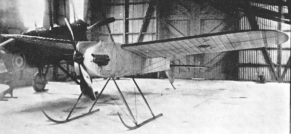
The Aerial Target. Note the aerial wires running vertically down the rear fuselage and chordwise on the wings.
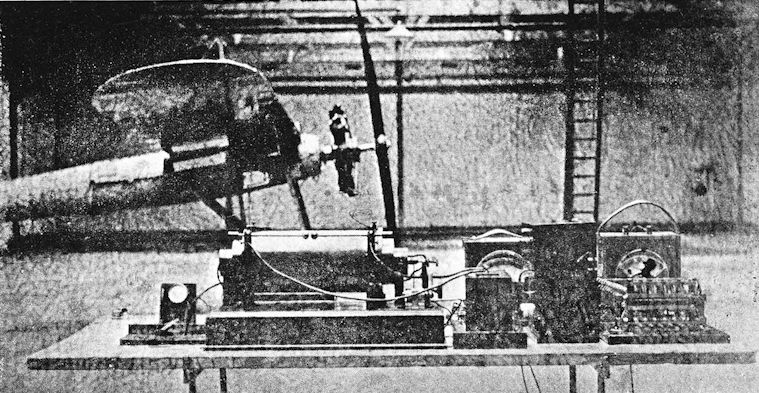
R.F.C. Experimental Works A.T. The first radio-controlled monoplane with Gnome rotary engine.
F.E.9
THE design of the F.E.9 was begun in 1916, and it seems probable that the type may have been intended to be a replacement for the F.E.2b. It was a two-seat fighter-reconnaissance biplane powered by a 200 h.p. Hispano-Suiza engine. The long nacelle was mounted high up in the gap between the mainplanes in order to give the observer the best possible field of fire all round. As on the F.E.8, the tailbooms converged in side elevation, and were attached to the rear spar of the tailplane.
The first machine, A.4818, had single-bay wing bracing with remarkably long extensions on the upper wings: the extensions were wire-braced in the usual manner of the period. Ailerons were fitted to the upper wings only, and had unusually large horn-balance areas. The second and third F.E.gs had modified interplane bracing with two bays of struts on either side.
The undercarriage was a very neat oleo structure attached to the lower centre-section, and the arrangement and relationship of the tail-skid and rudder resembled those of the S.E.5.
It was intended to build a further 24 machines but production did not proceed. A.4818 was used in a number of experiments, including tests with horn-balanced ailerons after their failure on the original B.E.12a, and investigations into rotational slipstream effects. It was found that the F.E.9 had a considerable tendency to turn under power, and experiments were conducted to determine the extent of yaw. The slipstream effect was measured by removing the fin and fitting a smaller balanced rudder, and immediately in front of the rudder a vertical rod was fitted. This rod was about four feet long, and bore eight pitot tubes which were connected to manometers. Readings of the manometers were recorded photographically.
In the summer of 1917, the F.E.9 was flown by Captain G. T. R. Hill, M.C., B.Sc., in a series of tests with differently-shaped horn-balance areas on the ailerons. The original large areas produced overbalancing, and the aircraft had a tendency to turn on to its back in a steep turn, particularly to the left. In this form the machine was flown with the fin area progressively reduced by stripping off portions of the fabric until finally all the fabric was removed. It was then almost impossible to use the ailerons at all, so completely did they overpower the rudder. The vertical tail surfaces underwent several modifications during the various experiments.
Two other types of ailerons were tested. The wing-tips were modified in shape so that the inboard line of the aileron horn balance was raked outwards instead of running fore-and-aft. The horn balance still lay within the wing contour, and was much smaller than the original surface; so much so that it was well-nigh ineffective. The final type of ailerons had projecting balance areas and proved to be the best of the three. Control was light, powerful and did not overpower the rudder in turns.
One of the F.E.9s went to a Home Defence squadron in 1917, but did not distinguish itself in any operational way.
SPECIFICATION
Manufacturers: The Royal Aircraft Factory, Farnborough, Hants.
Power: 200 h.p. Hispano-Suiza.
Dimensions: Span: upper (with final ailerons): 37 ft 9 1/2 in., lower 29 ft 5 1/4 in. Length: 28 ft 3 in. Height: 9 ft 9 in. Wheel track: 5 ft 5-4 in. Airscrew diameter: 8 ft 9 in.
Areas: Wings: 365 sq ft.
Weights: Loaded: 2,480 lb.
Performance: Maximum speed: 105 m.p.h. Climb to 5,000 ft: 8 min 25 sec: to 10,000 ft: 19 min 50 sec. Ceiling: 15,500 ft.
Armament: One Lewis machine-gun on pillar-mounting in front cockpit. A second gun could be fired rearwards from another pillar-mounting between the cockpits.
Service Use: One F.E.9 was sent to a Home Defence squadron in 1917.
Production: Three F.E.9s were built at the Royal Aircraft Factory in 1917.
Serial Numbers: A.4818-A.4844 were allotted for F.E.9s, but A.4821-A.4844 were not built.
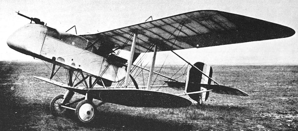
The first F.E.9 with ailerons similar to those of the original B.E.12a.
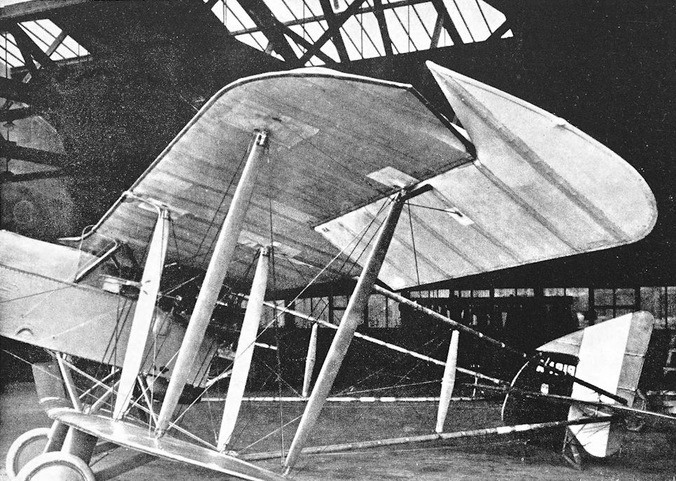
The second F.E.9, A.4819, showing the two-bay interplane bracing and modified fin and rudder. In this photograph (dated November 3rd, 1917) the aircraft is seen with the second type of ailerons to be tested.
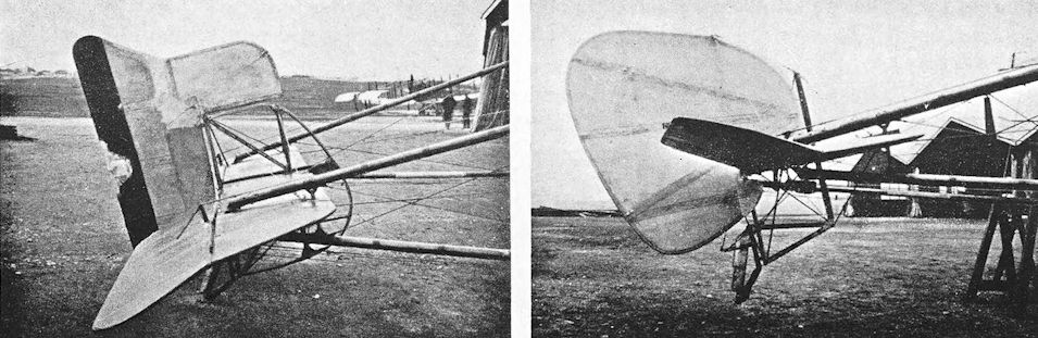
Left: The first F.E.9, A.4818, fitted with a rudder of the same basic shape as that of A.4819 but with an enlarged balance area. Photograph dated May 10th, 1917.
Right: A.4818 with fin removed and small balanced rudder. Photograph dated September 19th, 1917.
Right: A.4818 with fin removed and small balanced rudder. Photograph dated September 19th, 1917.
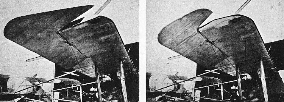
Left: The first F.E.9 with the original ailerons and final form of rudder. Photograph dated October 24th, 1917.
Right: The first F.E.9 with the third type of ailerons and final form of rudder. Photograph dated October 24th, 1917.
Right: The first F.E.9 with the third type of ailerons and final form of rudder. Photograph dated October 24th, 1917.
F.E.12
NEITHER the F.E.10 nor F.E.11 was built: the former was a projected single-seat fighter with a 200 h.p. Hispano-Suiza engine, and was to have had the pilot’s cockpit in front of the airscrew in much the same way as the observer’s nacelle was fitted to the B.E.9. The F.E.11 probably got no further than a preliminary layout sketch, for no records of it seem to have survived.
It is uncertain whether the F.E.12 was ever built, but an official document describes it as a large two-seat pusher biplane intended for use as a night fighter; it may have been related to the design of the N.E.1. The F.E.12 was designed for a 200 h.p. Hispano-Suiza engine, and its armament included a rocket-launching gun. However, its name does not appear in the official list of aircraft constructed at the Royal Aircraft Factory.
Drawings dated December, 1917, show the design to have been that of a two-bay equal-span pusher biplane equipped with two searchlights, one in the nose as on the N.E.1, the other apparently coupled to the rocket gun. A large wind-driven generator was slung under the nacelle. Two pillar mountings were provided for the rocket gun: one was between the cockpits, the other behind the rear cockpit. As on the first N.E.1, the pilot sat in front.
The nacelle was basically that of the F.E.9, and the undercarriage, tail-booms, gravity tank and tailskid were all F.E.9 components; while the fin and rudder resembled those of the N.E.1.
SPECIFICATION
Manufacturers: The Royal Aircraft Factory, Farnborough, Hants.
Power: 200 h.p. Hispano-Suiza.
Dimensions: Span: 50 ft. Length: 28 ft 1 1/2 in. Chord: 6 ft. Gap: 5 ft 6 in. Stagger: nil. Dihedral: 4 30'. Span of tail: 18 ft 2 in. Wheel track: 5 ft 5-4 in. Airscrew diameter: 8 ft 9 in. Areas: Wings: 550 sq ft. Ailerons: each 20-5 sq ft, total 82 sq ft. Tailplane: 30 sq ft. Elevators: 30 sq ft.
Weights: Loaded: 2,700 lb.
Armament: Included a rocket-launching gun.
N.E.1
THE N.E.1, or Night-flying Experimental, was another 1917 design. Like the F.E.12, it was a large pusher biplane, powered by the 200 h.p. Hispano-Suiza engine. Many components of the N.E.1 were identical to those of the F.E.9: the most obvious were the tail-booms, rudder, tail-skid and undercarriage legs.
The long wings were of equal span and had three-bay bracing; ailerons were fitted to upper and lower mainplanes. The divided undercarriage was of unusually wide track to facilitate night landings. The fin was a perfect semicircle and was symmetrical about the tailplane. The elevators had very large horn balances. The ultimate form of the design had (or was intended to have) the span of the centre-sections increased and the outer wing panels correspondingly shortened, a narrow-track oleo undercarriage similar to that of the F.E.9 and fitted with a cross-axle, and an enlarged fin. At least one N.E.1 is known to have had the larger fin. Drawings of this version indicate that bombs were to be carried under the lower centre-section.
The interest and significance of the N.E.1 lay in its equipment. In the nose of the rather inelegant nacelle was mounted a searchlight for target illumination, and the armament consisted of either a Coventry Ordnance Works quick-firing gun or a Vickers rocket gun, supplemented by Lewis guns. Moreover, the aircraft was fitted with one of the earliest radio telephony installations ever made in an aeroplane. The pilot sat in the front seat, presumably to facilitate the aiming of the searchlight. It was intended that the principal weapon should be carried on a substantial elevated mounting immediately behind and above the pilot.
The N.E.1 was not the first aeroplane to carry a searchlight, but it did anticipate some of the night interception methods practised during the war of 1939-45. Its performance is best summed up in the official report on the type:
“It is doubtful if the performance of this machine is good enough to make it suitable as a night fighter, though for short distance bombing at night it would be a slight improvement on the 160 Beardmore F.E.2b. An alternate scheme of fitting a B.H.P. engine into an F.E.2b would have great advantages.* There is a good deal of torque on the rudder with engine on, and the rudder bar is too near pilot, and not raised far enough above the floor. The machine is very heavy and awkward on controls, but easy to fly and land, and is very stable. Stalling speed very low, and machine pulls up quickly on landing. View and field of fire excellent.”
* Probably a reference to the F.E.2h.
A version of the design existed without the searchlight in the nose; the front of the nacelle was somewhat similar to that of the F.E.9. In this version the pilot sat in the rear cockpit and the rocket gun was on a pillar mounted on the front of the nacelle. The gunner therefore had greater freedom of movement and a wider field of fire, although he no longer had the assistance of the searchlight.
Neither form of the N.E.1 was developed, but the type provided the design basis for the A.E.3 or Farnborough Ram armoured ground-attack biplane.
At least one reference to a drawing of a single-seat version of the N.E.1 has survived, but it is unknown whether such an aircraft was built.
SPECIFICATION
Manufacturers: The Royal Aircraft Factory, Farnborough, Hants.
Power: 200 h.p. Hispano-Suiza.
Dimensions: Span: 47 ft 10 in. Length: 30 ft 2 in. with searchlight, 28 ft 6 in. without. Height: 9 ft 8 in. Chord: 6 ft. Gap: 5 ft 2 1/2 in. Stagger: nil. Dihedral: 4° 30'. Incidence: 2°. Wheel track: 13 ft 8 in. Tyres: 700 X 100 mm.
Areas: Wings: 555-1 sq ft.
Weights and Performance: No. of Trial Report: M.157. Date of Trial Report: November, 1917. Type of airscrew used on trial: T.28126, Series No. 21501. Weight empty: 2,071 lb. Military load: 185 lb. Crew: 360 lb. Fuel and oil: 330 lb. Loaded: 2,946 lb. Maximum speed at 10,000 ft: 95 m.p.h.; at 13,000 ft: 93 m.p.h.; at 15,000 ft: 89 m.p.h.; at 16,500 ft: 85 m.p.h. Climb to 1,000 ft: 1 min 35 sec; to 5,000 ft: 9 min; to 8,000 ft: 16 min 10 sec; to 10,000 ft: 22 min; to 14,000 ft: 39 min; to 16,000 ft: 53 min 10 sec; to 18,000 ft: 81 min 25 sec. Service ceiling: 17,500 ft. Absolute ceiling: 19,000 ft. Endurance: 2 3/4 hours.
Tankage: Petrol: main tank (behind pilot), 30 gallons; gravity tank, 10 gallons; total 40 gallons. Oil: 4 gallons. Water: 8 gallons.
Armament: One Coventry Ordnance Works quick-firing gun or one Vickers rocket gun; one Lewis machine-gun fixed on the starboard side of the nacelle to fire forward.
Production: Six N.E.1s were built, four in 1917 and two in 1918.
Serial Numbers: B.3971-B.3976.

N.E.1, serial number B.3971, with small searchlight in nose of nacelle.

Modified N.E.1 B3972 with experimental armament and searchlight removed.

Modified fin on N.E.1.
A.E.2
THE designation A.E.1 was an alternative name for the F.E.3, a remarkable two-seat pusher biplane built in 1913. The letters A.E. probably originally signified Armed Experimental, for the F.E.3 was used in experiments with a Coventry Ordnance Works one-pounder gun.
It is uncertain whether the A.E.2 was ever built. Its name does not appear in the official list of aeroplanes constructed at the Royal Aircraft Factory; but its derivation from another type by “reconstruction” cannot be excluded. In the case of the A.E.2 the designation signified Armoured Experimental. The aircraft was (or was to be) a tractor biplane with an armoured fuselage, possibly related to or developed from the armoured version of the B.E.2C, and presumably intended for ground attack duties. Unfortunately, in common with so many of its interesting contemporaries, only the fact of the existence of the design seems to have survived.
SPECIFICATION
Manufacturers: The Royal Aircraft Factory, Farnborough, Hants.
Dimensions: Span: 42 ft 7 in.
A.E.3, the Farnborough Ram
IN 1918 the A.E.3 appeared. It was a two-seat pusher biplane with an armoured nacelle, and was specifically designed for trench-strafing; a specially-designed gun-mounting on the front of the nacelle enabled a downward stream of fire to be poured into enemy trenches while the aeroplane was flying level. The engine was a 200 h.p. Sunbeam Arab, and three Lewis guns could be carried.
The A.E.3 was a development of the N.E.1 night-fighter, which in turn had been derived from the F.E.9. The nacelle of the A.E.3 was made of quarter-inch armour plate. Later, under the official scheme of nomenclature laid down in T.D.I. No. 538, the machine was named the Farnborough Ram: it was the only Royal Aircraft Factory type to have an official name.
Three A.E.3s were built. The Arab-powered version of the design was named Ram Mk. I, and a development of the type was built under the designation Ram Mk. II: the engine fitted to the later machine was the Bentley B.R.2 of 230 h.p. The first Ram Mk. II was made by fitting the B.R.2 engine to the third A.E.3 airframe, but there are indications that two Rams Mk. II existed. It is possible that a second may have been produced by converting a Ram Mk. I. In June, 1918, a Ram Mk. I was undergoing trials at Orfordness. It should be noted that at least one official document describes the engine of the Ram Mk. I as the 150 h.p. Hispano-Suiza and that of the Mk. II as the 150 h.p. Bentley B.R.1. There is reliable evidence that the Arab and the B.R.2 were the actual power units, however.
A development was projected under the designation Ram Mk. III. It was to have been powered by the B.R.1 engine, and was to have had a deep nacelle constructed of armour plate.
SPECIFICATION
Manufacturers: The Royal Aircraft Factory, Farnborough, Hants.
Power: Mk. I: 200 h.p. Sunbeam Arab. Mk. II: 230 h.p. Bentley B.R.2.
Dimensions: Span: 47 ft 10-5 in. Length: 27 ft 8 1/2 in. Height: 10 ft. Chord: 6 ft. Gap: 5 ft 6 in. Stagger: Nil. Dihedral: 5. Span of tail: 20 ft 2 in. Wheel track: 13 ft 8 1/2 in. (It was intended to fit wings of 7 ft chord to the Ram Mk. III.) Airscrew diameter: Mk. I, 8 ft 6 in.; Mk. II, 9 ft 3 1/2 in.
Performance: Maximum speed: 95 m.p.h.
Armament: Three Lewis machine-guns, one of which was on a telescopic-mounting between the cockpits, and could be fired rearwards.
Production: Three A.E.3s were built in 1918.
Serial Numbers: B.8781-B.8783. B.8781 was completed on March 30th, 1918; B.8782 in June, 1918; B.8783 in May, 1918.

A.E.3. Side elevation of the Farnborough Ram Mk.II (the B.R.2 engine is represented diagrammatically only).

Plan of the Ram Mk.II
C.E.1
ALTHOUGH the Royal Aircraft Factory experimented with a floatplane version of the original F.E.2 and the H.R.E.2 floatplane, it produced only one flying boat. It was designated C.E.1, or Coastal Experimental, and was a two-seat flying boat intended for coastal patrol duties.
The C.E.1 was designed by W. S. Farren (later Sir William Farren, C.B., M.B.E., F.R.S.), and was of similar layout to the much earlier Sopwith Bat Boats. The engine drove a pusher airscrew, and the tail-unit was carried on tail-booms. The hull was a planked wooden structure and had a single step; the after portion of the hull had a concave underside. The fin and rudder were symmetrical above and below the tailplane, and the rudder had a horn balance at each end.
The mainplanes could be folded backwards, reducing the width of the aircraft to 20 feet 7 inches. The structure of the wings at the point of fold was unusual. The wings of the C.E.1 were hinged on the rear spars at the points where the tail-booms met the wings; from that point on each wing the break-line ran obliquely forwards and inwards to the front centre-section struts. To facilitate folding, a short portion of the trailing edge of each mainplane immediately outboard of the tail-booms was hinged and had to be lowered before the wings were folded.
Work on the design began early in June, 1917, and two prototypes were laid down. So well did the work of construction proceed that the first, N.97, was completed and sent to Hamble on Christmas Day, 1917. The first C.E.1 was assembled there and was flown for the first time by Mr Farren on January 17th, 1918.
This machine was powered by the 230 h.p. R.A.F. 3a engine, which at first had shutters only on the upper half of its radiator. In its original form, N.97 had horn-balanced elevators, and the ailerons extended inboard almost as far as the second pair of interplane struts. Subsequent tests necessitated some modifications, and by the time the C.E.1 reached the Isle of Grain Experimental Station for Service trials, plain elevators were fitted and the ailerons had been shortened. The engine installation was also modified, and the radiator had shutters over its entire length.
In April, 1918, the C.E.1 was used in a series of experiments which were conducted to check the agreement of full-scale results with those obtained by the use of a model hull in the William Froude National Tank at the National Physical Laboratory. During these tests the machine was flown by Lieutenant Hackforth, and later trials were made by Captain Goodwin.
The second C.E.1, N.98, appeared in 1918. It differed from N.97 chiefly in having the 260 h.p. Sunbeam Maori engine in place of the R.A.F. 3a.
SPECIFICATION
Manufacturers: The Royal Aircraft Factory, Farnborough, Hants.
Power: 230 h.p. R.A.F. 3a; 260 h.p. Sunbeam Maori.
Dimensions: Span: 46 ft. Length: 36 ft 3 in. Height: 13 ft 4 in. Chord: 7 ft. Gap: 7 ft. Dihedral: 3 30'. Areas: Wings: 609 sq ft.
Weights (lb) and Performance:
Engine R.A.F. 3a Maori
No. of Trial Report N.M.132 N.M.20I
Date of Trial Report March 16th, 1918 July 30th, 1918
Type of airscrew used on trial T.28144 T.28188
Weight empty 3,241 3,342
Military load 710 581
Crew 360 360
Fuel and oil 601 711
Weight loaded 4,912 4,994
Maximum speed (m.p.h.) at
2,000 ft 88-5 92-5
5,000 ft 86 90
6,500 ft 85-5 87
m. s. m. s.
Climb to
2,000 ft 5 30 5 30
5,000 ft 18 10 17 10
6,500 ft 29 00 26 35
Ceiling (feet):
service 6,800 7,500
absolute 9,000 10,000
Endurance (hours) 4 1/2 3 3/4
Armament: Three partly movable mountings, each capable of carrying a Lewis machine-gun, were provided. One was fitted in front of the forward cockpit and two between the cockpits, one on either side. Bombs could be carried under the lower wings.
Serial Numbers: N.97, N.98.

The first C.E.1 afloat at Hamble, serial number N.97, with original long-span ailerons and horn-balanced elevators.

N.97 at the Isle of Grain with shortened ailerons and plain elevators.

The second C.E.1, serial number N.98.
The Ruffy-Baumann School Biplanes
THE Ruffy, Arnell and Baumann Aviation Co., Ltd., was formed in 1915 by Felix Ruffy, an Italian aviator, and Edouard Baumann, a Swiss who was an exponent of the Caudron biplane and who had acted as an instructor at the Beatty school when it was opened at Hendon in the spring of 1914.
The new company constructed several training biplanes of their own design. The first of these was a frank copy of the Caudron G.II, of which the Ruffy-Baumann concern operated several. An amusing account of the operation of the Ruffy-Baumann school is given by the celebrated Belgian fighter pilot, Willy Coppens, in his book Days on the Wing. Major Coppens was one of several distinguished pilots of the war years who “took their tickets” at the Ruffy-Baumann school.
<...>
The Ruffy-Baumann School Biplanes
<...>
The first truly original aircraft built by the Ruffy, Arnell and Baumann Aviation Co. was a clumsy single-seat biplane powered by a 60 h.p. Anzani six-cylinder radial engine. This machine had single-bay wing bracing, and the fuselage was faired to a more or less elliptical cross-section. Ailerons were fitted to the upper wing only, and were actuated by a system of rods and cranks. The machine was described, somewhat optimistically, as an advanced training biplane.
<...>
<...>
The first truly original aircraft built by the Ruffy, Arnell and Baumann Aviation Co. was a clumsy single-seat biplane powered by a 60 h.p. Anzani six-cylinder radial engine. This machine had single-bay wing bracing, and the fuselage was faired to a more or less elliptical cross-section. Ailerons were fitted to the upper wing only, and were actuated by a system of rods and cranks. The machine was described, somewhat optimistically, as an advanced training biplane.
<...>

Ruffy-Baumann Advanced Trainer.
FREDERICK SAGE & Co., Ltd., were an old-established firm of shop-fitters who had built up an excellent reputation for high quality woodwork. Early in 1915 they were asked by the Admiralty to undertake the manufacture of aircraft. The first contracts placed with the company were for airship work, and at the end of June, 1915, twelve Short 184 seaplanes were ordered. The first of these was flown less than three months later, and more Shorts were ordered.
In September, 1915, Sage & Co. secured the services of E. C. Gordon England as pilot and consultant. He had been one of Britain’s pioneer aviators, and came to Sages with considerable flying experience on a wide variety of types. By the end of 1915 Gordon England was placed in control of the company’s aeronautical department. Collaborating with Leonard Bonnard, he designed the Sage Type 1, a large twin-engined bomber which was intended to have two 190 h.p. Rolls-Royce engines. The most unusual feature of the Sage Type 1 was its undercarriage: two large main wheels were let into the floor of the fuselage, and there were auxiliary wheels at the wing-tips and nose. Thus the machine would have sat low on the ground, and the engines were mounted high up in the gap between the wings. The engines were also unusually far outboard and, since the undercarriage was within the fuselage, their weight was supported almost wholly by the wing bracing.
The Sage Type 1 was never completed, but early in 1916 work began on the Type 2.
<...>
Sage Type 2
<...>
The Sage Type 1 was never completed, but early in 1916 work began on the Type 2. The new machine was designed by Clifford W. Tinson, who had left the Air Department of the Admiralty to join Sages as their Chief Designer in January, 1916.
The Sage Type 2 was an attempt to produce an effective fighting aeroplane in the absence of a machine-gun interrupter gear. It was a remarkably small two-seat biplane of strikingly unusual appearance. The aeroplane was more or less designed around the observer’s gun, and emphasis was laid upon a wide and clear field of fire. To this end the observer, who occupied the rear seat, stood up with his head through the upper wing.
The arrangement was not unique. The French Nieuport 10 and the Austrian Lloyd biplane 40.05 of 1915 had similar firing positions for their front-seat observers; in the latter case a large, ugly fairing encased the observer’s body and filled the gap between fuselage and upper wing, incidentally depriving the pilot of any forward view. In 1916 two other Austrian aircraft had built-up over-wing positions for their back-seat observers: they were the Ufag-built Brandenburg C.I 64.01 and the Phonix-built Brandenburg C.I 26.17, but only the latter machine provided an enclosure for the pilot also.
On the Sage Type 2 a glazed cabin enclosed both members of the crew and filled the gap between the fuselage and the upper wing. Structurally the machine was typical of its period, and was a wire-braced wooden airframe. Considerable attention was paid to the reduction of drag: the 100 h.p. Gnome Monosoupape rotary engine was remarkably closely cowled, and a large spinner was fitted to the four-bladed airscrew. The single-bay wings were of unequal chord, and were interconnected by vee interplane struts: the nose portion of each wing was covered with plywood. Ailerons were fitted to the upper wing only, and were actuated by spanwise rods which ran along the rear side of the rear spar wholly within the wing. The outline of the rudder was reminiscent of that of the Bristol Scout, on which Mr Tinson had worked when he was with the British and Colonial Aeroplane Co. There was no fin.
The Sage Type 2 made its first flight on August 10th, 1916, and established performance figures which were exceptionally good for a two-seater with a maximum power of 105 h.p. It did not long survive, however, for in the course of a test flight at Cranwell on September 20th, 1916, the rudderpost failed. The aircraft became uncontrollable and, in attempting to land, it ran into a tree and was wrecked.
No attempt was made to develop the design, for practical interrupter gears had become available some months before the appearance of the Sage Type 2.
SPECIFICATION
Manufacturers: Frederick Sage & Co., Ltd., Peterborough.
Power: 100 h.p. Gnome Monosoupape.
Dimensions: Span: 22 ft 2 1/2 in. Length: 21 ft 1 5/8 in. Height: 9 ft 6 in. Chord: upper 5 ft, lower 2 ft 8 in. Gap:
5 ft 6 in. Dihedral: 2. Incidence: upper 5, lower 3. Span of tail: 9 ft 5 in. Airscrew diameter: 8 ft.
Areas: Wings: upper 100 sq ft, lower 68 sq ft, total 168 sq ft. Ailerons: each 12-5 sq ft, total 25 sq ft. Tailplane: 20 sq ft. Elevators: 14-5 sq ft. Rudder: 9 sq ft.
Weights: Empty: 890 lb. Loaded: 1,546 lb.
Performance: Maximum speed at ground level: 112 m.p.h.; at 10,000 ft: 109-75 m.p.h.; at 15,000 ft: 104 m.p.h.
Climb to 5,000 ft: 6 min 30 sec; to 10,000 ft: 14 min 45 sec; to 15,000 ft: 35 min. Ceiling: 16,000 ft. Endurance: 2 1/2 hours.
Tankage: Petrol: 27 1/2 gallons. Oil: 8 gallons.
Armament: One Lewis machine-gun mounted above the upper wing and fired by the observer.
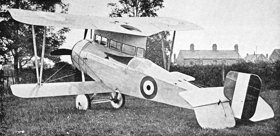
Sage Type 2.
Sage Type 3
THE Sage Type 3 was designed in 1916 at the request of the Air Department of the Admiralty for a primary trainer. The principal requirements were for robustness and a low landing speed.
The Sage Type 3 emerged in January, 1917, as a two-bay biplane powered by the 75 h.p. Rolls-Royce Hawk engine. Six experimental machines were ordered, and there was the prospect of substantial production to follow. The machine was entirely conventional in appearance and construction. The undercarriage was somewhat reminiscent of that of the Armstrong Whitworth F.K.8, but two small wheels were fitted at the forward end of the horizontal skid.
The prototype, N. 5280, first flew on January 5th, 1917, and a large order for the type was placed by the Admiralty. Production had just begun when the Admiralty cancelled the contract and asked Sages to concentrate on the development of seaplanes.
The performance of the Type 3 was rather poor, even for a trainer. The prototype underwent some modification and was fitted with smaller vertical tail surfaces; the all-up weight was reduced somewhat and the maximum speed was increased by 4 m.p.h. In its modified form the machine was known as the Type 3b, and the original form was retrospectively re-designated Type 3a.
SPECIFICATION
Manufacturers: Frederick Sage & Co., Ltd., Peterborough.
Power: 75 h.p. Rolls-Royce Hawk.
Dimensions: Span: 34 ft 6 in. Length: 32 ft 10 in. Height: 10 ft 9 in. Chord: 4 ft 9 in. Gap: 5 ft. Stagger: 11-8 in. Dihedral: 2 30'. Incidence: upper 3, lower 5. Span of tail: 11 ft 4 in. Airscrew diameter: 8 ft.
Areas: Wings: 330 sq ft. Ailerons: each 18 sq ft, total 72 sq ft. Tailplane: 26 sq ft. Elevators: 24 sq ft. Fin: 4 sq ft. Rudder: 10 sq ft.
Weights: Empty: 1,390 lb. Loaded: Type 3a, 2,064 lb; Type 3b, 1,980 lb.
Performance: Type 3a. Maximum speed at ground level: 72 m.p.h. Climb to 5,000 ft: 20 min. Ceiling: 9,000 ft. Endurance: 4 hours. Type 3b. Maximum speed at ground level: 76 m.p.h. Ceiling: 9,000 ft. Endurance: 4 hours.
Tankage: Petrol: 26 gallons. Oil: 4 gallons.
Serial Number: N.5280.

Sage Type 3.
Sage Types 4a, 4b, 4c
IN the summer of 1917 there appeared the Sage Type 4a, a two-seat float seaplane designed for patrol duties. The airframe differed very little from that of the Sage 3, and many components were identical.
The engine of the seaplane was the 150 h.p. Hispano-Suiza, which was fitted with twin stack-type exhausts; and single control only was provided in the forward cockpit.
The observer occupied the rear cockpit, in which a wireless installation was fitted. The floor of the rear cockpit was constructed to slide and give the observer a clear view directly downwards. The view from both cockpits was very good. The Sage 4a made its first flight on July 3rd, 1917, and underwent official trials some time later. It was not accepted as a patrol seaplane, but was recommended for adoption as a training aircraft.
A considerable amount of re-designing had to be done to convert the machine into a trainer. Dual control was fitted, and the engine mounting was modified in order to take a variety of engines of 200 h.p. The trainer version of the design was re-designated Sage Type 4b, but the modifications occupied ten months and it did not fly until May 17th, 1918.
When the Sage 4b appeared, it was powered by a 200 h.p. Sunbeam Arab engine driving a four-bladed airscrew. In appearance it was conventional but considerably cleaner than most contemporary British seaplanes. Its basic structure consisted of the usual wire-braced wooden framework, but the machine was characterised by excellent detail design. The undercarriage consisted of two main floats of pontoon type, and a small tail-float which was fitted with a water rudder.
The Sage 4b underwent its official trials at the Isle of Grain.
A few months later, Sages produced a folding-wing version of the type under the designation Sage Type 4c. This was an almost completely new design, but looked very similar to the Sage 4b. It was a new aeroplane, bearing the serial number N.117.
The chief structural modification in the Sage 4c was the fitting of folding wings; but the wings themselves were new, and were of increased span and chord. Additional interplane struts were fitted at the inboard ends of the mainplanes in order to preserve the truss with the wings folded. The tail-unit was redesigned, as the areas quoted in the dimensional tables show, but the only noticeable change was the straight leading edge on the tailplane: all previous Sage types had had slight sweep-back on the tailplane leading edge.
The Sage 4c was fitted with a 200 h.p. Hispano-Suiza engine, driving a two-bladed airscrew. The main floats were somewhat larger than those of the Sage 4b. Further refinements in detail design were incorporated in the Sage 4c, and it would have been easy to produce and maintain. Provision was made for the fitting of a wheel undercarriage if necessary.
The Sage 4c first flew on October 12th, 1918, and underwent its official trials on October 25th. In the air it handled well. It was stable about all axes, yet was so manoeuvrable that normal aerobatics were within its capabilities. In November, 1918, the Sage 4c was used to test the application of the Gosport system of flying instruction to seaplanes.
Both the Sage 4b and 4c had been adopted as standard British training seaplanes for 1919, but the Armistice was signed before contracts could be placed, and no production was undertaken.
SPECIFICATION
Manufacturers: Frederick Sage & Co., Ltd., Peterborough.
Power: Sage 4a: 150 h.p. Hispano-Suiza. Sage 4b: 200 h.p. Sunbeam Arab. Sage 4c: 200 h.p. Hispano-Suiza.
Dimensions:
Aircraft Sage 4a Sage 4b Sage 4c
Span 34 ft 6 in. 34 ft 6 in. 39 ft 7J in.
Length 32 ft 6 in. 34 ft 37 ft 6 in.
Height 11 ft 3 in. - 11 ft 7 in.
Chord 4 ft 9 in. 4 ft 9 in. 5 ft 3 in.
Gap 5 ft 5 ft 3 in. 5 ft 3 in.
Stagger 11-8 in. 1 ft 2-7 in. 1 ft 4-7 in.
Dihedral 2° 30' 2° 30' 3°
Incidence: Upper 3° 3° 3° 10'
Lower 5° 5° 3° 10'
Span of tail 11 ft 4 in. - 11 ft
Airscrew diameter 9 ft - 9 ft
Areas (in sq ft):
Wings 330 330 386
Ailerons: Each 18 18 21
Total 72 72 84
Tailplane 26 26 24-4
Elevators 24 24 21-2
Fin 4 5 5-5
Rudder 10 9 8
Weights (lb) and Performance:
Aircraft Sage 4a Sage 4b Sage 4c
No. of Trial Report - - N.M.237
Date of Trial Report - - October 25th, 1918
Type of airscrew used on trial - - A.B.7202
Weight empty 1,620 - 2,215
Military load - - Nil
Crew - - 360
Fuel and oil - - 300
Weight loaded 2,662 2,709 2,875
Maximum speed (m.p.h.) at
sea level 83-5 95-5 -
3,000 ft - - 97-2
6,500 ft - - 96-6
10,000 ft 79 85-1 93-7
13,000 ft - - 83-1
m. s. m. s. m. s.
Climb to
1,000 ft - - - - 1 30
2,000 ft - - - - 3 00
3,000 ft - - - - 4 30
4,000 ft - - - - 6 00
5,000 ft 12 00 - - 8 00
6,000 ft - - - - 10 00
7,000 ft - - - - 12 15
8,000 ft - - - - 15 00
9,000 ft - - - - 17 50
10,000 ft 32 00 25 00 21 20
I 1,000 ft - - - - 25 30
12,000 ft - - - - 30 15
13,000 ft - - - - 36 50
Ceiling (feet): service - - 13,700
absolute 12,600 14,400 15,800
Endurance (hours) 4 2 1/2 2 1/2
Tankage: Petrol: Sage 4a, 48 gallons: Sage 4b and 4c, 35 1/2 gallons. Oil: Sage 4a, 6 gallons; Sage 4b and 4c, 4 1/2 gallons.
Service Use: No Sage seaplane saw operational service. The Sage 4b and 4c were tested at the Isle of Grain.
Production: One Sage 4a was built and later converted to the Sage 4b. One Sage 4c was built.
Serial Numbers: N. 116: Sage 4a, later 4b. N.117: Sage 4c.

Sage Type 4b.

Sage Type 4c. The Sage 4c with wings extended.

THE SAGE TYPE 4c SEAPLANE: This machine is very similar to the Type 4b , except that it has folding wings.
Saunders T.1
THE boat-building firm of S. E. Saunders Ltd. became associated with the aircraft industry in its earliest days, for Saunders-built hulls were fitted to several of the first British flying boats. After the outbreak of war the company undertook the manufacture of several standard types of aircraft, including the Avro 504, Short 184 and Norman Thompson N.T.2B, and also built some flying-boat hulls for Commander Porte’s experiments at Felixstowe.
It was not until 1917 that the first all-Saunders aeroplane appeared. It was a two-seat tractor biplane designed by H. H. Thomas, from whose surname its designation of T.1 was derived.
The Saunders T.1 was intended to have either a wheel or float undercarriage, but it is doubtful whether it was ever flown in the latter form. It was of uninspiring appearance, and was a simple single-bay biplane with wire-braced extensions on the upper wings; ailerons were fitted to the upper mainplanes only. The structure of the wings and tail unit was conventional, with fabric covering on a wooden structure; but the fuselage was built of Saunders’ patent “Consuta” copper-sewn plywood, and contained neither metal fittings nor bracing wires. Full dual control was fitted, and all engine controls and instruments were duplicated in the rear cockpit.
The aircraft was designed to have the 200 h.p. Hispano-Suiza engine. At the time of its appearance, however, all engines of that type were wanted for S.E.5a’s, and none could be spared for installation in the Saunders biplane. A 150 h.p. Sunbeam Nubian was fitted, and with it the Saunders T.1 was test-flown from Cowes aerodrome by a Major Evans, an R.F.C. pilot who had seen service in France. The machine is said to have performed well despite its reduced power, and the only serious difficulty experienced during the trials was a tendency for the engine to overheat and boil the cooling water. Unfortunately H. H. Thomas died in the influenza epidemic of 1918, and the design was not developed.
SPECIFICATION
Manufacturers: S. E. Saunders Ltd., Cowes, Isle of Wight.
Power: 150 h.p. Sunbeam Nubian, engine No. 5530.
Dimensions: Span: upper 37 ft 5 in., lower 24 ft 9 in. Chord: upper and lower, 5 ft 6 in. Gap: 5 ft 6 in. Stagger: nil. Dihedral: 2° 30'. Incidence: 2° 15'. Span of tail: 14 ft.
Areas: Wings: 314 sq ft. Ailerons: 21 sq ft. Tailplane: 33-5 sq ft. Elevators: 22 sq ft. Fin: 5-5 sq ft. Rudder: 8 sq ft.
Tankage: Petrol: main tank 35 gallons.
Armament: The observer had a Lewis machine-gun on a Scarff ring-mounting, and there was a gun for the pilot: official diagrams show a fixed Lewis gun, synchronised to fire forward through the airscrew.
Serial Number: X. 14, built under Licence No. 13.

Saunders drawing of the T.1, showing the early smoke-stack exhaust, lower mainplane cutouts and rear Lewis gun. No photographs of the Saunders T.1 seem to have survived. This sketch of the aircraft was made in 1918 by a member of the S. E. Saunders design team.

General Arrangement drawings of the Saunders T.1.
Short S.38
THE great British firm of Short Brothers had been building aircraft for many years before war broke out in 1914. Their connexion with the R.N.A.S. began early in 1911 when Mr (later Sir) Francis McClean lent two of his aeroplanes to the Admiralty for the purpose of teaching Naval officers to fly. Mr McClean had been Short Brothers’ first customer, and one of the machines he lent to the Admiralty was the Short No. 34, or S.34.
The designations of aeroplanes used by the R.N.A.S. are extremely confusing and, when read in conjunction with Shorts’ system of designating their products, they become more confusing still. Short Brothers generally named their types by using the works number of the first machine of a particular type to distinguish all subsequent aeroplanes of the same basic type. The Admiralty practice was to take the serial number allotted to the first machine of a particular type, or, more confusingly, the serial number of an aircraft of the first production batch, and to identify all machines of that type by that number. Examples of the R.N.A.S. system are the Avro 179, Short 184 and Wight 840.
The so-called Short S.34 was a development of the Short S.27 Box-kite of 1910. Extensions were added to the upper wing, and a small nacelle was provided for the protection of the pilot. The engine was a 70 h.p Gnome.
So many of the early Short biplanes were rebuilt in so many different ways, some retaining their original works-cum-type number, that it is now well-nigh impossible to trace development with complete accuracy. It seems fairly certain, however, that the Short biplane type which became known as the S.38 was a derivative of the S.27 type. There are, in fact, indications that the aeroplane which became known as the Short S.38 was originally a biplane of the S.27 type, and was rebuilt into the form which itself became recognised as a basic type. The rebuilt S.38 was flying in October, 1912.
The reconstruction was a drastic one. The wing span and area were greatly increased, a new set of tail-booms and a completely re-designed tail-unit were fitted, and the nacelle was enlarged to accommodate both the pilot and a passenger.
The S.38 re-emerged as a large three-bay pusher biplane with an 80 h.p. Gnome rotary engine. A forward elevator was fitted: on the original S.38, as a legacy from the basic S.27 design, this front elevator was carried on booms which projected forward from the innermost interplane struts on each side; but later aircraft of the S.38 type had a small forward elevator mounted on the prow of the nacelle. The tailbooms were parallel in side elevation, and carried two straight-edged rudders at their extremities. The struts and skids of the undercarriage were the rectangular structures which had been used on the S.27, and the original Short S.38 retained the long cross-axle bearing two wheels. On later S.38s each skid bore two wheels on short axles. The long extensions of the upper wing were tapered and had a small dihedral angle. The observer sat behind the pilot; dual control was fitted to some S.38s, and the aircraft seemed well-suited to training duties.
A modified form of undercarriage was later used, in which front and rear legs of the struts were raked forward and diagonal struts were added for greater rigidity. The rudders were also modified in shape to have a slightly steeper downward slope on their upper edges. Ultimately, balanced rudders of rounded outline were standardised: these were similar to the rudders of Francis McClean’s S.70 seaplane in which he flew up the River Nile. The S.38 could be flown as a seaplane, and at least one machine was fitted with floats. A four-bay version existed, and some S.38s dispensed with the forward elevator.
A few Short S.38s were in service with the R.N.A.S. when the war broke out. One or two were used for coastal patrols during the early months of the war, armed with a single rifle wielded by the observer. The type continued in use as a trainer for some time, and was built in small numbers by other contractors.
SPECIFICATION
Manufacturers: Short Brothers, Eastchurch, Isle of Sheppey.
Other Contractors: White & Thompson, Ltd., Middleton, Bognor Regis, Sussex (built eighteen Short 8.38s). Pemberton-Billing, Ltd., Woolston, Southampton.
Power: 80 h.p. Gnome.
Dimensions: Span: upper 52 ft, lower 34 ft. Length: 35 ft 6 in.
Weights: Empty: 1,050 lb.
Performance: Maximum speed: 58 m.p.h. Endurance: 5 hours.
Armament: Normally one rifle, fired by the observer. One S.38 had a Maxim machine-gun mounted on the nose of the nacelle.
Service Use: Coastal Patrol: R.N.A.S. Station, Great Yarmouth. Training: R.N.A.S. Stations, Chingford and Eastchurch.
Serial Numbers: 2, 19, 28, 34, 62-65, 1580-1591: built by Pemberton-Billing, Ltd. 3143-3148: built by White & Thompson, Ltd. 8434-8439: built by White & Thompson, Ltd. 8530-8541: built by White & Thompson, Ltd.
Notes on Individual Machines: 34: originally had 50 h.p. Gnome; was used as armament training aircraft at Eastchurch. 64: stationed at Eastchurch. 65: had both wheel and float undercarriages.
Short Biplane, Admiralty No. 3
THE Short biplane which bore the official serial number 3 appeared in the form seen in the illustration in the summer of 1913. It had been rebuilt from a Short of earlier type, possibly a modified S.27, and was a simple two-seat pusher biplane powered by an 80 h.p. Gnome engine. In the reconstruction it acquired wings similar to those of the Short 74 seaplane and a tail-unit which closely resembled that of the S.38.
The Short No. 3 was flown at Eastchurch, and some of the early naval pilots trained on it. In October, 1914, it was sent to France to augment the heterogeneous equipment of Commander C. R. Samson’s squadron, which was then based at Poperinghe. In his book Fights and Flights Commander Samson wrote: “An addition to our Squadron was old No. 3, whose age I would be sorry to state; but an aeroplane had to be in a pretty bad way before we sent it home.” It is doubtful whether No. 3 was ever put to any serious use, however.
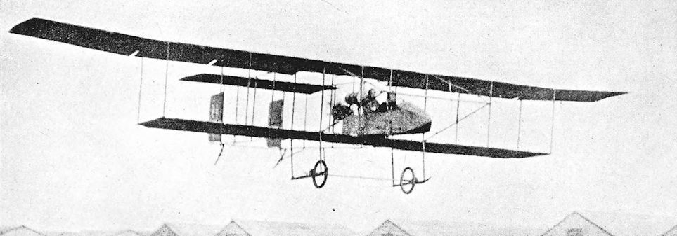
Short S.38. The first S.38, with original form of front elevator and rudders.
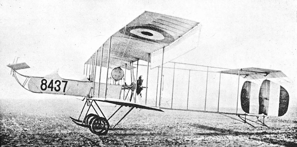
Production-type S.38 trainer built by Norman Thompson Flight Co in 1915. Ultimate form of the design, with small forward elevator, improved undercarriage, and new rudders.
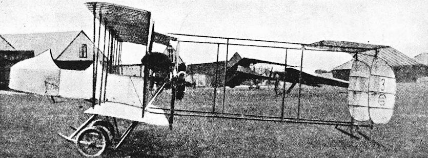
Short Biplane, Admiralty No. 3.
Short S.41
THE Short S.41 was a tractor biplane, powered by the 100 h.p. Gnome two-row rotary engine, which was designed in 1911 and appeared early in 1912 as a landplane. The wheel undercarriage was soon replaced by twin pontoon-type single-step floats; these were close together, and there were air-bags under the wings to stabilise the aircraft when on the water.
The S.41's fuselage, which was of rectangular cross-section, was mounted above and clear of the lower wing. There were extensions on the upper wing, braced by long sloping struts to the lower ends of the outer interplane struts. Ailerons were fitted to the upper wings but they had no balance cables, and consequently hung down limply when the machine was at rest. Both upper and lower centre-sections were uncovered. There was no fin, but a strut braced the top of the rudder to the fuselage.
The first S.41 was flown at the 1912 review of the Fleet, which was held on May 8th at Weymouth. Commander C. R. Samson was one of the pilots who flew the machine a good deal, and the S.41 may have been the Short seaplane to which an early wireless transmitter and receiver were fitted in May, 1912: the range was from 3 to 5 miles.
Standardisation in aircraft design was then virtually unknown, and later machines, although nominally S.41s, differed in many ways from the prototype. A slightly refined S.41 which saw much service was No. 20, a seaplane which was delivered to the air station at Great Yarmouth in July, 1913. In the preceding May, No. 20 had been fitted with wireless apparatus which was tested successfully in the air by Lieutenant R. Fitzmaurice; the Short was flown by Sub-Lieutenant J. T. Babington. The machine later took part in the Naval manoeuvres of 1913.
The fuselage of No. 20 was almost identical to that of the original S.41, but the wing-bracing differed in having king-posts and cable-bracing for the upper wing extensions in place of the original lift struts. The floats had no steps; the small stabilising floats were right out at the lower wing-tips; and the shape of the rudder was more rectangular. Upper and lower centre-sections were covered in, and longer ailerons were fitted.
Like so many of its contemporaries, No. 20 was not particularly manageable when out of its natural element. It is recorded in The Story of a North Sea Air Station that “To start No. 20 up was a feat of strength and was rarely accomplished in a short time”. Moreover, it was not easy to beach the machine, for its wooden floats were delicate structures.
At Great Yarmouth experiments were made with wheel attachments on the floats, the whole device being known as the G.R.W. Wheel Float Attachment.The initials were obtained from the surnames of the joint inventors: Lieutenant-Commander R. Gregory, Engineer-Lieutenant E. W. Riley, and Mr White, an official of Chatham Dockyard. The aircraft could be taxied on the wheels, which could be released once the machine was afloat. The tests of the G.R.W. gear were carried out by Lieutenant-Commander Gregory himself early in 1914, but further experiments were abandoned on the outbreak of war.
No. 20 carried out coastal patrols from Great Yarmouth, and was still in service in June, 1915.
SPECIFICATION
Manufacturers: Short Brothers, Eastchurch, Isle of Sheppey.
Power: 100 h.p. Gnome.
Dimensions: Span: upper 50 ft, lower 34 ft 9 in. Length: 39 ft. Height: 11 ft 9 in. Chord: 6 ft 11 in. Gap: 7 ft.
Stagger: nil. Dihedral: nil.
Weights: Empty: 1,100 lb.
Performance: Maximum speed: 60 m.p.h. Endurance: 5 hours.
Service Use: Flown at R.N.A.S. Stations, Great Yarmouth and Eastchurch.
Serial Numbers: 10, 20, 21.

The original Short S.41 seaplane.

The Short S.41, serial number 20, flown at Great Yarmouth. The aircraft is here seen fitted with the G.R.W. Wheel Float Attachment.
Short Biplane, Admiralty No. 42
AT the Aero Show which was held at Olympia in 1913 Short Brothers exhibited an excellent float seaplane which bore a family resemblance to the earlier S.41 seaplane and was developed from that type.
The new Short was an unequal-span biplane powered by an 80 h.p. Gnome rotary engine. The engine was unusually well enclosed: a semi-circular cowling with frontal aperture was fitted, and continued aft as a rounded top-decking as far as the cockpit; the lower half of the engine was covered by a specially shaped sheet of metal which conformed to the contours of the bottom longerons. As exhibited at Olympia, the machine was a three-seater.
The lower wings were attached directly to the fuselage, which was deeper than that of the S.41. The tailplane was mounted below the upper longerons, and there was no fixed fin. The undercarriage consisted of two long pontoon floats and a small tail-float; small floats were fitted under the lower wing-tips. This thoroughly workmanlike seaplane was purchased by the Admiralty on the instruction of Mr (later Sir) Winston Churchill, who was at that time First Lord of the Admiralty. With the official serial number 42 it was flown by the Naval Wing of the R.F.C. and took part in the 1913 Naval manoeuvres, when it was based at Leven. In Naval service it was normally flown as a two-seater. On July 27th it stove in one of its floats on alighting and had to be towed back. It was later fitted with a wheel undercarriage which incorporated two long skids, and was flown in this form at Montrose.
It seems that No. 42 remained a landplane thereafter, for it was still in service in that form when war broke out. On August 27th, 1914, it went to France as part of the heterogeneous collection of aircraft which formed the equipment of Commander Samson’s Eastchurch Squadron of the R.N.A.S. It was flown in France, and survived until September 28th, 1914, when Commander Samson flew it into a tree after the engine had failed on take-off.
SPECIFICATION
Manufacturers: Short Brothers, Eastchurch, Isle of Sheppey.
Power: 80 h.p. Gnome.
Dimensions: Span: upper 48 ft, lower 30 ft. Length: 35 ft. Airscrew diameter: 8 ft 6 in.
Areas: Wings: 390 sq ft.
Weights: Empty: 1,200 lb. Loaded: 1,971 lb.
Performance: Maximum speed: 65 m.p.h.
Service Use: R.N.A.S. Squadron at Dunkerque, September, 1914.
Serial Number: 42.

Short Biplane No. 42. The Short is seen here in its original seaplane form, exhibited at the 1913 Olympia Aero Show.

Short S.60 (RNAS No.42) at Montrose after conversion to land chassis was built in 1913 and written off in France in September 1914.
Short S.81 Gun-carrier
EXPERIMENTS with aircraft armament in the Naval Wing of the R.F.C. were put on an official footing on July 29th, 1913. On that date Lieutenant R. H. Clark-Hall, R.N., was placed in charge of the work. By the end of 1913 three semi-automatic guns had been ordered and issued for practical tests which were to be conducted by both the Naval and Military Wings.
The first of these three experimental weapons was a 1 1/2-pounder Vickers gun which was delivered to the Navy. It was intended to mount this gun first in the Navy’s Astra Torres airship and later in a Sopwith Gun Bus.
Ultimately, however, a special seaplane was ordered from Short Brothers to enable the gun to be tested properly. The machine had the Short works number S.81, and was designed by A. Camden Pratt. It was a large pusher float seaplane, powered by a 160 h.p. Gnome engine. The wings had three bays of struts, and there were long extensions on the upper mainplanes, braced in the same way as those of the enlarged Folder tractor floatplane. Ailerons, which had no balance cables, were fitted to the upper wings only.
The nacelle was conventional in appearance, but its design presented some problems in stressing for the recoil of a semi-movable quick-firing gun. The tail-unit resembled that of the Short S.38; and the undercarriage consisted of two main floats and two tail-floats. A small float was fitted under each wingtip.
It has been said that when the Vickers gun was fired the force of the recoil was so great that the S.81 stopped dead and dropped 500 feet. Be that as it may, the S.81 is next heard of at the R.N.A.S. Station, Great Yarmouth, early in 1915. There it was again used to test a heavy weapon: in March and April, 1915, experiments were carried out with a 6-pounder Davis gun fitted to the S.81. The recoil difficulty did not arise in the case of the Davis gun, however, for it was a double-ended affair which fired a blank charge rearwards at the same time as it fired its projectile.
Whatever the outcome of these experiments, the Short S.81, or Gun-carrier as it was popularly called, vanished from the R.N.A.S. scene.
SPECIFICATION
Manufacturers: Short Brothers, Eastchurch, Isle of Sheppey.
Power: 160 h.p. Gnome.
Armament: One 1 1/2-pounder Vickers semi-automatic gun, mounted on the nose of the nacelle; later one 6-pounder Davis gun was fitted.
Service Use: R.N.A.S. Station, Great Yarmouth.
Serial Number: 126.
Short Seaplane, Admiralty Type 74
TO its makers, this seaplane was known as the Short Improved S.41. That designation is somewhat misleading, for the type bore little external resemblance to the original S.41 or to succeeding Short seaplanes derived from the S.41. The official designation, Type 74, was derived from the serial number of a typical production aircraft.
In appearance the Short 74 seemed to owe more to the Short No. 42 than to any development of the S.41. The fuselage was similar in general outline to that of No. 42, and the lower wings were attached directly to it. The engine, however, was the 100 h.p. ten-cylinder Gnome rotary; and a new, balanced rudder of less angular appearance was fitted. The tail-unit embodied a triangular fin. The mainplanes had three bays of bracing, and the extensions of the upper wings were strut-braced. The long ailerons were of the single-acting type, and ran for about two-thirds of the length of the trailing edge on each side.
Several Short 74s were built and were in service in 1914, some of them at Dundee seaplane station. A flight of these Short seaplanes was sent to Spithead in July, 1914, to take part in the Naval Review.
After the outbreak of war the Short 74s remained in service for some months and were chiefly employed on coastal patrol duties. The most important action in which Short seaplanes of this type participated was the daring attack launched against the airship sheds at Cuxhaven on Christmas Day, 1914. Of the seven British seaplanes which had been taken to the Heligoland Bight in the vessels Arethusa, Engadine and Riviera, three were Short 74s. The raid did not succeed in its planned object, but much useful information about German naval ports was obtained and the seaplanes’ bombs did a good deal of damage.
SPECIFICATION
Manufacturers: Short Brothers, Eastchurch, Isle of Sheppey.
Power: 100 h.p. Gnome.
Armament: Bombs could be carried on external racks.
Service Use: R.N.A.S. Stations, Calshot, Isle of Grain and Dundee.
Serial Numbers: 74-80, 180, 182, 183, 811-818. No. 811 (Flight-Lieutenant C. H. K. Edmonds), No. 814 (Flight Sub-Lieutenant V. Gaskell-Blackburn) and No. 815 (Flight-Commander D. A. Oliver) attacked Cuxhaven on December 25th, 1914.
Short Folder Seaplane
EARLY in 1913 Short Brothers took out patents for methods of folding the wings of aeroplanes. The first drawings had been made by Horace Short in 1912, and he had then set about the construction of aircraft embodying the device.
The first British aircraft to have folding wings was the Short seaplane which bore the official serial number 81; it appeared in 1913, and was closely followed by a second machine, No. 82. These seaplanes bore a strong resemblance to the Improved S.41 type (Admiralty Type 74), particularly in the design of fuselage and tail-unit: they were in fact frequently referred to as S.41s. The wings were of similar configuration, with long strut-braced extensions on the upper mainplanes; but Nos. 81 and 82 had only two bays of interplane struts, whereas the Short 74 had three. The engine was the big 160 h.p. Gnome, a two-row fourteen-cylinder rotary, and the cowling was surmounted by a substantial funnel-like exhaust stack. The pilot occupied the rear cockpit, and had a short decking and headrest behind his seat.
The Short No.81 took part in the Naval manoeuvres of July, 1913; it was one of the two aircraft carried by the seaplane carrier Hermes, which was attached to the “Red” fleet. The seaplane was fitted with a Rouzet wireless telegraphy transmitter, which was used in the course of the exercises. Thanks to its wireless installation, No. 81 was successfully retrieved after being forced down some 50 miles from the Hermes on August 1st: the machine’s probable position was determined from the last messages transmitted to the Hermes. The crew of No. 81 on this occasion were Commander C. R. Samson and Lieutenant R. Fitzmaurice.
The use of this Short seaplane from a carrier vessel proved to be satisfactory, thanks in some measure to its folding wings, and it was realised that this type of aircraft had a considerable future.
Further folding-wing seaplanes were built and delivered to the Naval Wing of the R.F.C. (which did not acquire its fully separate identity as the Royal Naval Air Service until June 23rd, 1914). These later Shorts had three-bay wings of increased area; the extensions on the upper wings were lengthened, and the bracing was slightly modified. It was possible on the later machines to fold the wings from the cockpit. The arrangement of the float-struts was simplified. Four of the 160 h.p. Gnome-Shorts were at the Royal Naval Review which was held on July 18th-22nd, 1914, at Spithead.
One of these four machines was part of the Calshot Flight, which was under Squadron Commander A. M. Longmore (later Air Chief Marshal Sir Arthur Longmore, G.C.B., D.S.O.). After the review, the First Lord of the Admiralty, Winston Churchill, visited Calshot and discussed the experiments with torpedo-carrying aircraft which were then being conducted. The first successful flight with a 14-inch torpedo had been made by a Sopwith Type C seaplane late in 1913, but it seems doubtful whether a successful drop had been made, even by July, 1914. Mr Churchill requested that the work be accelerated. Squadron Commander Longmore told him that it could be done with a 160 h.p. Short seaplane, and undertook to make a torpedo drop within a short time.
Special drawings were prepared at short notice by Horace Short as soon as he received the official requirements: new cross-bars for the floats were made at once; and Squadron Commander Longmore has recorded that he made the first successful drop from the Short on July 28th. The torpedo was a 14-inch missile which weighed 810 lb. (Historically, however, this achievement was some three years behind the first torpedo drop ever made: in 1911 Captain Guidoni, an Italian, took off with and dropped a 352-lb torpedo, using a Farman biplane.)
War was declared a week later, and the torpedo experiments continued during August, 1914. On the outbreak of war the Admiralty allocated three 160 h.p. Shorts, equipped to carry torpedoes, to the aircraft carrier Engadine. These machines were never used for torpedo attacks, however, although one torpedo sortie against a German cruiser nearly took place.
At least eight seaplanes of the 160 h.p. Gnome type were on the strength of the R.N.A.S. at the outbreak of hostilities, and were doubtless used for coastal patrol work during the early months of the war. Two of the Engadine's Short Folders were among the seven Short seaplanes which bombed Cuxhaven on Christmas Day, 1914.
Three Short Folders were sent to Africa in March, 1915, to provide air reinforcements for the naval forces which were bent on the destruction of the German light cruiser Konigsberg. The enemy vessel had been lying well up the delta of the Rufiji river since October, 1914. The delta consisted of such a maze of channels that only air reconnaissance could establish her exact position. In November, 1914, the Kinfauns Castle brought a Curtiss flying boat, the property of Gerard Hudson, a mining engineer, from Durban. This machine made several successful reconnaissances before being wrecked on December 10th, 1914.
On February 21st, 1915, two Sopwith 807 seaplanes arrived at the tiny island of Niororo; it was hoped to bomb the Konigsberg with them, but they proved quite unsuitable for the work.
In March, 1915, the armed liner Laconia brought three 160 h.p. Gnome Short seaplanes to Durban; the aircraft reached Niororo on April 23rd. These Shorts were in poor condition, but were good enough for reconnaissance work. The first flight was made on April 25th; photographs were taken despite the Short’s refusal to climb higher than 600 feet. This machine was brought down by rifle-fire from the ground, but was successfully towed back to Niororo.
The rather elderly Shorts carried out several reconnaissances at the cost of one of their number (fortunately without the loss of its crew), but it was obvious that they were not truly capable of doing the work required of them. They were supplanted in June, 1915, by two Henri Farman F.27s and two Caudron G.IIIs. The Konigsberg was finally destroyed on July 11th, under the observation of one of the Farmans and one of the Caudrons.
SPECIFICATION
Manufacturers: Short Brothers, Eastchurch, Isle of Sheppey.
Power: 160 h.p. Gnome
Dimensions: Span: original machines, upper wings 56 ft, lower 40 ft. Later (three-bay) version, upper wings 67 ft.
Length: 39 ft. Chord: 6 ft. Gap: 6 ft. Stagger: nil. Dihedral: nil. Airscrew diameter: 9 ft 6 in.
Areas (original machines): Wings: 550 sq ft.
Weights: Empty: 2,000 lb. Military load: 80 lb. Crew: 360 lb. Fuel and oil: 600 lb. Loaded: 3,040 lb.
Performance: Maximum speed: 78 m.p.h. Initial rate of climb: 600 ft per min. Endurance: 5 hours.
Tankage: Petrol: 65 gallons. Oil: 15 gallons.
Armament: Bombs could be carried on external racks. A few machines were fitted with early torpedo crutches and could carry one 14-in. torpedo.
Service Use: R.N.A.S. Stations, Isle of Grain, Westgate and Calshot. Aircraft carriers Engadine and Riviera. German East Africa: R.N.A.S. detachment, Niororo Island.
Serial Numbers: 81,82, 89, 90, 119-122, 186. Nos. 119 (Flight-Commander R. P. Ross) and 120 (Flight-Lieutenant A. J. Miley) attacked Cuxhaven on December 25th, 1914.

An early Admiralty Type 74, No 76, without folding wings, with top of engine cowling removed; this type was adapted in 1915 to carry up to a pair of 112 lb bombs.

An early two-bay Short Folder seaplane employing Short's patented wing-folding system; note the single-acting ailerons which conveniently permitted the necessary clearance of the tail unit when folded.

Short Folder Seaplane. Modified Folder with three-bay wings.

Three-bay Short Folder No 120 at the RNAS Station, Westgate, in about September 1914. It had previously been at Calshot where it had been flown on 21 July with a dummy torpedo, weighing little more than 500 lb; as far as is known it never flew with the real 810 lb weapon, but this was said to have been due to a recalcitrant engine. No 120, carrying bombs and flown by Flt-Lt Arnold John Miley RN, accompanied the raid against Cuxhaven on Christmas Day, 1914.
This Short Folder was the first seaplane to be used at the R.N.A.S. Station, Westgate. Its serial number provides an example of the duplications which occurred in the pre-war period: the original No. 120 was a Henri Farman biplane.
This Short Folder was the first seaplane to be used at the R.N.A.S. Station, Westgate. Its serial number provides an example of the duplications which occurred in the pre-war period: the original No. 120 was a Henri Farman biplane.
Short Seaplane, Admiralty Type 135
THE Short seaplane which was known as Admiralty Type 135 was ordered in September, 1913; design work began at the end of that year, and the first machine emerged in 1914.
The aircraft was a development of the Short Folder seaplane which had the 160 h.p. Gnome rotary engine; like its predecessor, the Type 135 also had folding wings. Its construction was entirely conventional. There were two bays of interplane bracing and, as on the original Folder, the long extensions of the upper wings were braced by struts. Single-acting ailerons were fitted to the upper wings only; each aileron was made in two sections, and the inboard portions had inverse taper. Two machines, numbered 135 and 136, were built: the first had the 135 h.p. Salmson engine, a single-row water-cooled radial, and the second had the 200 h.p. two-row Salmson. Only the first machine had been delivered by the time the war began.
The 200 h.p. Salmson engine was a fourteen-cylinder two-row radial of Swiss origin. In common with the other Salmson engines of the period it was frequently referred to as a Canton-Unne, a name which was derived from the surnames of its joint designers.
The two-row radial engine gave the nose of No. 136 a distinctive appearance: by way of cowling only a rudimentary hood was fitted, and there was a large block-like radiator on top of the fuselage. The rudder was balanced and a low aspect-ratio fin with curved leading edge was fitted. The two main floats were simple wooden pontoon structures, and there was a tail-float.
The famous sortie of Christmas Day, 1914, against Cuxhaven has already been mentioned in the history of the Short 74. Both Short 135s were among the seven machines which carried out the raid. No. 136 had been delivered to the Isle of Grain in September, 1914, and on the Cuxhaven raid it was flown by Flight-Commander C. F. Kilner with Lieutenant Erskine Childers as his observer. On their way back to the waiting seaplane carriers in the Heligoland Bight these officers made a detailed reconnaissance of German fleet units in the Schillig Roads.
No. 136 went to the Dardanelles as one of the eight assorted seaplanes in the new carrier vessel Ark Royal, which left Sheerness on February 1st, 1915. This Short seaplane was quite the best machine the Ark Royal then had, and proved to be the only one capable of operating in bad weather. On April 27th, 1915, however, one of the undercarriage struts was shot through by ground fire and broke when the machine alighted. The strut was replaced, but when No. 136 next tried to take off, the struts on both sides buckled; the engine was submerged and thereafter could never be persuaded to run well again.
SPECIFICATION
Manufacturers: Short Brothers, Eastchurch, Isle of Sheppey, and at Rochester.
Power: 135 h.p. Salmson (Canton-Unne); 200 h.p. Salmson (Canton-Unne).
Dimensions: Span: upper 54 ft 6 in., lower 40 ft. Length: 39 ft. Height: 12 ft 6 in. Chord: 6 ft. Gap: 6 ft. Stagger: nil. Dihedral: nil. Distance between float centres: 8 ft.
Weights: Loaded: 3,700 lb.
Performance: Maximum speed: 60-65 m.p.h. Endurance: 4 hours.
Armament: Bombs could be carried on external racks.
Service Use: R.N.A.S. Station, Isle of Grain; seaplane carrier Ark Royal.
Serial Numbers: 135, 136.

Short Seaplane, Admiralty Type 135 (Short S.87, RNAS No.136) after the collapse of its undercarriage. It was one of two machines built in 1914 with Sunbeam engines.
Short Seaplane, Admiralty Type 166
FOLLOWING the successful experiments in torpedo-dropping made with a Short Folder seaplane, work was begun on the design of a new Short seaplane, developed from the Short 135. The new machine was designed from the beginning as a torpedo-carrier and, like the Short 135, was fitted with a 200 h.p. Salmson fourteen-cylinder two-row radial engine. The aircraft became officially known as the Admiralty Type 166: the designation was derived from the serial number of a machine of the first batch.
The Short 166 was a thoroughly workmanlike seaplane. The fuselage was the usual wire-braced wooden structure with rounded top-decking. The first machine, No. 161, had no cowling of any kind on the engine, but later Short 166s had a small cap-like cover over the uppermost cylinders in line with the fuselage top-decking. The radiator was a large, clumsy affair, mounted on top of the fuselage just in front of the wings. The mainplanes had two bays of struts, and the extensions of the upper wings were wire-braced: there were king-posts above the outer interplane struts. In this feature the Short 166 differed from the Short 135, which had strut-braced extensions. The later type had slightly larger wings to provide the area required to lift a torpedo, and its ailerons did not extend inboard beyond the outer pair of interplane struts; the ailerons were one-piece surfaces and had compound inverse taper. The mainplanes could be folded.
A balanced rudder was fitted, and a large low aspect-ratio fin was a conspicuous feature of the tail-unit: it had a curved leading edge, and was of the shape and proportions which became and remained a characteristic feature of Short seaplanes until the S.364 and N.2B appeared.
The main floats were typical wooden pontoon-type structures, spaced by two steel tubes which were arched in the middle to accommodate a torpedo. The tail-float was fitted with a water-rudder.
Only a few Short 166s were built by Short Brothers themselves, and there is no record that the type ever used a torpedo operationally. By the end of 1915 the seaplane carrier Ark Royal, then at Salonika, had five Short 166s, one of which was No. 166 itself.
In 1916 a batch of twenty Short 166s were built by the Westland Aircraft Works. They had no provision for carrying a torpedo: straight cross-bars connected their floats, and their offensive load consisted of three 112-lb bombs. The Westland-built Short 166s were crated and sent to Hamble by rail. There they were assembled and were tested by Sidney Pickles on behalf of Short Brothers.
SPECIFICATION
Manufacturers: Short Brothers, Rochester.
Other Contractors: Westland Aircraft Works, Yeovil, Somerset.
Power: 200 h.p. Salmson (Canton-Unne).
Dimensions: Span: upper 57 ft 3 in., lower 42 ft. Length: 40 ft 7 in. Height: 14 ft of in. Chord: 6 ft. Gap: 6 ft 3 in. Stagger: nil. Dihedral: nil. Incidence: 5.
Areas: Wings: 573 sq ft.
Weights: Loaded: 4,580 lb.
Performance: Maximum speed: about 65 m.p.h.
Armament: One 14-in. torpedo weighing 810 lb, or three 112-lb bombs. The observer could have a Lewis machine-gun.
Service Use: R.N.A.S. Station, Calshot. Aegean: “A” Squadron, R.N.A.S., Thasos. The seaplane carrier Ark Royal had five Short 166s at Salonika in January, 1916.
Serial Numbers: 161-166: built by Short Brothers. 9751-9770: built by Westland Aircraft Works.
Notes on Individual Machines: 166: H.M.S. Ark Royal, Salonika. 9758: “A” Squadron, R.N.A.S., Thasos (this aircraft was reported to be there on February 6th, 1917). 9770: R.N.A.S., Calshot.

Short Admiralty Type 166 with arched spacers between floats to carry the torpedo.
Short Seaplane, Admiralty Types 827 and 830
ALMOST contemporary with the Short 166 was the slightly smaller floatplane which was powered with either the 135 h.p. Salmson radial engine or the 150 h.p. Sunbeam Nubian water-cooled vee-eight. The first batch of twelve, numbered 819-830, were ordered in the summer of 1914; it was intended that six machines should have the Salmson engine and six the Sunbeam. The Salmson-powered seaplanes were to be 819-821 and 828-830, but 827 also had that engine at one time.
Under the Admiralty’s illogical and unpredictable system of nomenclature, the Sunbeam-powered Short was known as the Short Seaplane Type 827, whilst that with the Salmson was designated Type 830.
In structure and appearance the Short 827/830 bore a very close resemblance to the Short 166. Identification of the Short 827 was facilitated by its Sunbeam engine, and the 830 could be distinguished from the Short 166 by the straight trailing edge on its inversely tapered ailerons, which extended inboard of the outer struts; by the plain steel-tube interplane struts, the slight forward rake of the rear centresection struts, and by the slightly less bulky engine. There were two bays of interplane bracing, and the extensions of the upper wings were braced by cables. The mainplanes could be folded. Once again there was a large radiator block mounted on top of the fuselage in front of the wings, for the 135 h.p. Salmson, like the 200 h.p. engine of the same make, was a water-cooled radial. The Short 827/830 was not designed to carry a torpedo. The first Short of the new type was delivered to the R.N.A.S. in 1914.
A number of Short 830s were built, but the Sunbeam engine was standardised for the type and the Short 827s ultimately outnumbered the 830s. The only visible differences between the airframes were those necessitated by the use of the vee-eight engine in place of the radial. The Short 827 was built by Parnall & Sons, the Fairey Aviation Company, the Sunbeam Motor Car Company, and the Brush Electrical Engineering Company, in addition to the parent firm.
An improved version of the 830 existed. It had rigid trailing edges on the mainplanes in place of the wire which was used on the standard machine; and constant-chord ailerons were fitted. The observer had a Lewis gun mounted in an opening in the upper centre-section.
The Short 827s began to appear in numbers in 1915, and the type remained in service until the Armistice. In home waters it was used for oversea patrols from stations such as Calshot and Great Yarmouth. One of the Yarmouth 827s bombed the German Fleet at 4.05 a.m. on April 25th, 1916, when the enemy carried out his bombardment of Lowestoft.
The Short 827 was used in other theatres of war. Three were sent to Mombasa in July, 1915, where they were to have been collected by the R.N.A.S. personnel who had assisted in the destruction of the cruiser Konigsberg and were on their way to participate in the campaign in German East Africa. However, by the time the party reached Mombasa orders had already been received for the Shorts to go to Mesopotamia.
Despite the transfer of these three Short 827s the type nevertheless participated in the East African campaign, for in March, 1916, an R.N.A.S. detachment arrived at Zanzibar equipped with four Voisins and four Short 827s. This unit was later known as No. 8 (Naval) Squadron. The seaplanes operated from Chukwani Bay, but greater mobility was obtained by using three ships as seaplane carriers: the armed liner Laconia, the armed merchant cruiser Himalaya, and the aircraft carrier Manica each had one Short 827.
These seaplanes did a good deal of useful work in the coastal operations of the East African campaign. They contributed to the success of the operations at Dar-es-Salaam in August, 1916, and in the following month the attack on Bagamoyo was based on air photographs taken by the Mamed’s seaplane. The landings at Lindi, Sudi Bay, Kilwa and Kisiju were all covered by the Short 827s. In June, 1917, Flight Sub-Lieutenant C. F. M. Chambers and his observer, Petty Officer Mechanic F. Wilmshurst, flying the Manicds Short 827, contributed reconnaissance charts which were used in the preparation of maps for the advance from Lindi.
Four Short 827s were ultimately handed over to the Belgian forces in East Africa. If they were in fact the four which were used by No. 8 (Naval) Squadron, their serviceability record must have been unequalled by any contemporary seaplanes.
The three Short 827s which had left Mombasa for Mesopotamia in July, 1915, reached Basra at the beginning of September; these machines were all equipped with wireless transmitters. They proved to be of little use, however, for they were unable to get an adequate take-off run from the waters of the Tigris; once airborne their rate of climb in the hot climate was too poor.
Aircraft were sorely needed at that time, and in October two of the Short 827s were converted to landplanes by the substitution of “home-made” wheel undercarriages for the floats. At the beginning of December, 1915, these Shorts took part in the bombing of the Turkish forces advancing on Kut al Imara.
The Shorts were withdrawn to Basra for refit on December 4th. In January, 1916, it was decided to form a composite Flight of R.N.A.S. and R.F.C. personnel at Ora, and the Shorts were flown there. One was wrecked on January 31st; a second was damaged in a bad landing on February 4th; and on February 14th the third turned over on landing and was wrecked.
A small number of Short 827s were used in the Mediterranean: they were based at Otranto, whence four were sent early in 1917.
SPECIFICATION
Manufacturers: Short Brothers, Rochester.
Other Contractors: The Brush Electrical Engineering Co., Ltd., Loughborough; The Fairey Aviation Co., Ltd., Hayes, Middlesex; Parnall & Sons, Ltd., Mivart Street, Eastville, Bristol; The Sunbeam Motor Car Co., Wolverhampton.
Power: 135 h.p. Salmson (Canton-Unne); 150 h.p. Sunbeam Nubian.
Dimensions: Span: upper 53 ft 11 in., lower 40 ft. Length: 35 ft 3 in. Height: 13 ft 6 in. Chord: 5 ft. Gap: 5 ft 6 in. Stagger: nil. Dihedral: nil.
Areas: Wings: 506 sq ft.
Weights: 135 h.p. Salmson. Empty: 2,622 lb. Military load: nil. Crew: 360 lb. Fuel and oil: 342 lb. Weight loaded: 3,324 lb. 150 h.p. Sunbeam. Weight loaded: 3,400 lb.
Performance: Salmson. Maximum speed at 2,000 ft: 70 m.p.h. Climb to 2,000 ft: 10 min 25 sec. Endurance: 3 1/2 hours. Sunbeam. Maximum speed: 61 m.p.h.
Armament: Bombs could be carried on racks under the fuselage. A Lewis machine-gun could be carried: on one Short 830 the gun was fitted on a special mounting in the upper centre-section.
Service Use: R.N.A.S. Stations, Calshot, Dundee, Killingholme, Isle of Grain and Great Yarmouth. Short 830 used on aircraft carriers Engadine and Ben-my-Chree. East Africa: No. 8 (Naval) Squadron: four Short 827s, three of which were disposed on board the armed liner Laconia, the armed merchant cruiser Himalaya, and the aircraft carrier Manica. Four 827s were later handed over to the Belgians in East Africa. Mesopotamia: R.N.A.S. Flight at Basra. Mediterranean: Seaplane station at Otranto. Seaplane carriers Raven II and Ben-my-Chree.
Production and Allocation: Serial numbers indicate that at least nineteen Short 830s and 107 Short 827s were ordered. On October 31st, 1918, the R.A.F. had four Short 827s on charge. Three were at seaplane stations in the United Kingdom and one was in the Mediterranean.
Serial Numbers: Short 830: 819-821, 827-830 and 1335-1346 were built by Short Brothers. Short 827: 822-826: built by Short Brothers. 3063-3072: built by Short Brothers. 3093-3112: built by Short Brothers. 3321-3332: built by Brush Electrical Engineering Co. 8218-8229: built by Parnall & Sons. 8230-8237: built by Brush Electrical Engineering Co. 8250-8257: built by Parnall & Sons. 8550-8561: built by Fairey. 8630-8649: built by Sunbeam.
Notes on Individual Machines: Used by R.N.A.S., Great Yarmouth: 3104, 3105, 3108, 3109, 8222, 8637. Used by R.N.A.S., Calshot: 3326, 3332, 8228, 8229, 8551, 8559. Other machines: 820 and 821: used on H.M.S. Ben- my-Chree. 829: R.N.A.S., Isle of Grain; interned by Holland, November nth, 1914. 3093-3095 were sent to East Africa and were later handed over to the Belgians. 3096-3098 were presented by the Overseas League; 3098 was used in East Africa. 8219 was handed over to the Belgians in East Africa. 8226-8229 were fitted with dual control. 8226: R.N.A.S., Killingholme. 8645: R.N.A.S., Dundee.
Short (140 h.p. Salmson) Seaplane, 1916
THIS seaplane has come to be regarded as a close relative of the Short 827 and 830, though it was in fact a new design. There were certain points of similarity between the types, but the later Salmson-powered seaplane was a somewhat larger aircraft than the Short 827/830.
Possibly the use of the single-row Salmson radial engine suggested a closer relationship to the Short 830 than existed in fact. There was a general similarity in the disposition of the cockpits and interplane struts; and only bracing details distinguished the undercarriage of the later machine from that of the 827 and 830.
However, the Salmson-powered seaplane of 1916 had a lengthened fuselage, larger fin, and wings of increased span. Double-acting ailerons were fitted to the upper wings, and all interplane struts were faired. The centre-section had a large circular aperture, presumably to give the observer ready access to the retrieving sling and to facilitate hoisting-in. It may also have been possible to mount a Lewis gun on the centre-section. The wings could be folded.
Only ten machines were built. No doubt the 140 h.p. Salmson-Short proved to be underpowered in relation to the Service needs of its time; and by that time the Short 184 had been adopted as the standard patrol seaplane.
SPECIFICATION
Manufacturers: Short Brothers, Rochester.
Power: 140 h.p. Salmson.
Service Use: R.N.A.S. Station, Calshot.
Production: Ten Short seaplanes of this type were built.
Serial Numbers: 9781-9790.

An Admiralty Type 827 off the German East African coast, probably one of those sent to Mombasa in July 1915 for operations against the Konigsberg in the Rufiji delta.

Short Admiralty Type 830.

Modified Short 830 with rigid trailing edges, constant-chord ailerons, and Lewis gun mounted in the centre-section.

Short (140 h.p. Salmson) Seaplane.
Short Bomber
POSSIBLY because the R.N.A.S. might be required to put its aircraft to a wide variety of uses, the Air Department of the Admiralty early displayed an admirable flexibility of thought towards the design of aeroplanes. In 1915 the Admiralty proposed a competition for the design of a large bombing aeroplane and a fighting scout.
Short Brothers’ entry in the former category was a landplane conversion of the Short 184 seaplane. The prototype had the fuselage of a standard Short 184, complete with 225 h.p. Sunbeam engine; but the flying controls were placed in the rear cockpit, presumably to enable the observer to use the machine’s defensive Lewis gun which was mounted above the centre-section. To fire this gun the observer had to stand erect on the coaming between the two cockpits. A cumbersome four-wheel undercarriage was fitted, and there was a sprung tail-skid.
The landplane had completely different wings from those of the seaplane. Only two bays of interplane struts were at first fitted, and there were long extensions on the upper wings; king-posts were fitted above the outer struts. The upper wings were of constant chord, whereas those of the Short 184 had a slight inverse taper. Later, the span was increased considerably by the insertion of a third bay on each side; the upper wings retained their long extensions.
The machine promised well as a bomber, for its great wing area enabled it to lift what was then regarded as a substantial load. The type was ordered in some numbers, not only from Short Brothers, but from four other contractors.
The Sunbeam company were one of the four, and the Short Bombers built by them had the 225 h.p. Sunbeam engine. All the other production machines were fitted with the new 250 h.p. Rolls-Royce engine which was later named Eagle. No matter what engine was fitted, however, the radiator was installed in two elements, one on either side of the engine; the Sunbeam-built machines could be distinguished by their single central exhaust stack.
The earliest production Bombers had fuselages of the same dimensions as the Short 184, but later machines had much longer fuselages: presumably this modification was made to improve longitudinal control. All production machines, of whatever type, had the observer in the rear cockpit. Dual control was provided, and the fuel tanks were armoured.
A Short Bomber which was tested at the Isle of Grain in 1916 had a fin with a straight, sloping leading edge in place of the characteristic curve. This machine is believed to have been the modified prototype. It had the lengthened fuselage, and the modified fin was probably expected to be sufficiently large in view of the longer moment arm provided by the extended fuselage. Production Short Bombers appeared with the original curved fin, however. The production aircraft became available late in 1916, and were first in action on the night of November 15th of that year. The new machines had been supplied to No. 7 Squadron, R.N.A.S., of the 5th Wing at Coudekerque, and on that night four of them participated in the raid on Ostend. On that occasion each Short Bomber carried eight 65-lb bombs.
Ostend and Zeebrugge frequently provided targets for the Shorts, but difficulty was experienced with water and oil freezing during the winter of 1916-17; the sustained operational use of the big Shorts was consequently no easy matter.
The load and range of the Short Bomber had helped to foster the first ideas of strategic bombing of enemy munition and industrial centres in the Saar. In the spring of 1916 it was arranged that a bomber force would operate from Luxeuil; and in May of that year Captain W. L. Elder, R.N., went to France to prepare for the arrival of the new unit, which was to be known as No. 3 Wing, R.N.A.S. Its equipment was to consist of fifteen Short Bombers and twenty Sopwith 1 1/2-Strutters, with an ultimate total strength of too aircraft, and it was the true beginning of the Independent Force of 1918.
When the preparations for the establishment of the new Wing were well in hand, the Admiralty received an urgent request from General Trenchard. He asked the Admiralty to release as many aircraft as possible to enable the R.F.C. to make up its serious deficiencies in time for the Somme offensive, which was timed to begin on July ist, 1916. Owing to various difficulties of supply both at home and in France, the R.F.C. was short of no less than twelve squadrons.
The Admiralty responded generously to this plea, and handed over a number of 1 1/2-Strutters immediately. Whether any Short Bombers were transferred to the R.F.C. at this particular time is uncertain, but at least fifteen of them were in fact handed over. The Admiralty’s action seriously retarded the building of the R.N.A.S. 3rd Wing, which did not begin to operate until October 12th, 1916. It is doubtful whether any Short Bombers were on the Wing’s strength at that date.
The Short Bomber did not remain in service for long. Early in 1917 the Handley Page O/100s began to arrive, and their much greater bomb-carrying capacity made them more effective weapons than the Shorts.
SPECIFICATION
Manufacturers: Short Brothers, Rochester.
Other Contractors: Mann, Egerton & Co., Ltd., Prince of Wales Road, Norwich; Parnall & Sons, Ltd., Mivart Street, Eastville, Bristol; The Phoenix Dynamo Manufacturing Co., Ltd., Bradford; The Sunbeam Motor Car Co., Ltd., Wolverhampton.
Power: 225 h.p. Sunbeam; 250 h.p. Rolls-Royce (Eagle).
Dimensions: Span: 85 ft. Length: 45 ft. Height: 15 ft. Chord: 6 ft. Gap: 6 ft 3 in. Stagger: nil. Areas: Wings: 870 sq ft.
Weights: Loaded: 6,800 lb.
Performance: Maximum speed at 6,500 ft: 77-5 m.p.h. Climb to 6,500 ft: 21 min 25 sec; to 10,000 ft: 45 min. Service ceiling: 9,500 ft. Endurance: 6 hours.
Armament: One Lewis machine-gun on ring-mounting on rear cockpit. The bomb-load consisted of four 230-lb or eight 112-lb bombs, carried on racks under the lower wings.
Service Use: No. 7 Squadron, R.N.A.S. 5th Wing; R.N.A.S. 3rd Wing.
Production and Allocation: The following table shows the number of Short Bombers built by each contractor and the number transferred to the R.F.C.:
Contractor Number built Transfers to R.F.C.
Short Brothers 36 4
Mann, Egerton 20 10
Parnall & Sons 6 -
Phoenix Dynamo 6 1
Sunbeam 15 -
Totals 83 15
One Short-built Bomber was transferred to the French Government.
Serial Numbers: 3706: prototype, built by Short Brothers. 9306-9340: built by Short Brothers. 9356-9370: built by Sunbeam. 9476-9495: built by Mann, Egerton. 9771-9776: built by Parnall. 9831-9836: built by Phoenix. A.3932: Phoenix-built Short Bomber apparently renumbered on transfer to the R.F.C.
Notes on Individual Machines: 9311: transferred to French Government. Used by R.N.A.S. 5th Wing: 9330, 9335, 9336, 9338, 9357, 9490, 9491, 9776, Transfers to the R.F.C.: 9315, 9319, 9320, 9325, 9476-9479, 9482-9485, 9487, 9488.

Original two-bay Bomber prototype 3706 with 225 h.p. Sunbeam engine at Eastchurch in 1915, showing the proposed Lewis gun mounting, for which a retractable telescopic fairing was intended to protect the gunner while standing.

Short Bomber. The modified prototype with extended wings.

Early production Short Bomber with short fuselage and Rolls-Royce engine, built by Mann, Egerton & Co. Aircraft serial number 9476.

Short Bomber. Late production aircraft No. 9834, with long fuselage, built by the Phoenix Dynamo Manufacturing Co.

Short Bomber with modified fin at the Isle of Grain in 1916. This photograph was faked for propaganda purposes, and is actually a composite of four views of the same aircraft.
Short Seaplane, Admiralty Type 184
SQUADRON Commander A. M. Longmore had proved the feasibility of dropping a torpedo from an aeroplane in July, 1914, and his accomplishment confirmed Commodore Murray F. Sueter, then Director of the Air Department of the Admiralty, in his opinion that the torpedo-carrying aeroplane had considerable potentialities and was worth developing.
Short Brothers had produced the Short 166 seaplane, equipped with torpedo-carrying gear, soon after the outbreak of hostilities, but it appears that the Air Department of the Admiralty wanted a larger and more powerful torpedo-carrier, and regarded the development of such an aircraft as a matter of urgency. Commodore Sueter therefore sent for Horace Short and explained the new requirements to him. Within a few weeks design work on a new seaplane type was well advanced, and early in 1915 there emerged a large Short seaplane, powered by a 225 h.p. Sunbeam engine, and capable of carrying a torpedo between the main floats of its undercarriage. This machine bore the official number 184, and by that number the type was known: namely, as the Short Type 184. Unofficially, however, it was popularly known as the “Two-two-five”, a name derived from the horse-power of its engine.
The long three-bay wings were of equal span, and were arranged to fold; there was a small float under each lower wing-tip. The main floats were typical pontoon structures, and the fin and rudder had the characteristic form which had already been seen on the Short 166. When No. 184 first appeared it had ailerons on the upper wings only, and they had no balancing cable to interconnect them: they therefore hung down limply when there was no airstream to support them. A balancing cable was later fitted, and finally interconnected ailerons were fitted to both upper and lower wings: all production machines were built in that form. No. 184 itself later had a plain rudder without balance area, and the fin was modified accordingly.
The Short Type 184 made history during the Dardanelles campaign, for it became the first aircraft in the world to sink an enemy ship at sea by means of a torpedo. On June 12th, 1915, the seaplane carrier Ben-my-Chree arrived at lero Bay, Mitylene; her equipment included three Short Type 184 seaplanes, one of which was the original No. 184 itself. On August 12th, one of the carrier’s Shorts took off, loaded with a 14-inch torpedo; its pilot was Flight-Commander C. H. K. Edmonds, and his orders were to attack enemy shipping. No observer was carried, but the Short would not climb higher than 800 feet. Off Injeh Burnu Edmonds sighted a large steamer. He glided down to a height of fifteen feet, released his torpedo at a range of 300 yards, and saw the missile strike his target squarely.
On August 17th Edmonds sank another Turkish ship, this time from a range of 800 yards; and on the same day Flight-Lieutenant G. B. Dacre sank a large steam tug in False Bay.
Apparently the Short 184 had justified itself in a short time, and indeed these successes must be recognised for the wonderful achievements which they were. In practice, however, the machine was difficult to operate. When loaded with a torpedo the Short could take off only in ideal weather: a calm sea and a slight breeze were essential, and the engine had to be running perfectly. Moreover, the weight of the torpedo was so great that only a limited amount of fuel could be carried, and the flight endurance was little more than three-quarters of an hour.
So it was that the Short 184 was no more heard of as a torpedo-carrying aircraft - save in somewhat ignominious circumstances in January, 1918. Then the German cruiser Goeben lay aground south of Nagara after an abortive sortie from the Dardanelles, and strenuous efforts were being made to disable her completely. Bombing proved fruitless, and an attempt was made to fit a 14-inch torpedo to one of the old Short 184s of the Ark Royal: it was probably the only available aircraft fitted with torpedo crutches. However, the old machine refused to rise from the water with its load.
During the war other torpedo attacks by Short 184s were attempted, and the type was used for torpedo experiments and for training in torpedo dropping at Felixstowe; but the first fine successes were never repeated. At least one of the Felixstowe Shorts was flown solo, and had the rear cockpit faired over.
But if it did not again shine as a torpedo aircraft, the Short 184 still had a brilliant war record in several theatres of war and in several capacities. It participated in many bombing raids, made spotting flights for ships’ guns, carried out a vast amount of patrol work in many waters, and even attempted anti-Zeppelin patrols.
If we continue the story of the Ben-my-Chree’s Shorts we find that they had a distinguished history. On November 8th, 1915, Edmonds and Dacre each flew a Short 184 overland to bomb the railway bridge over the River Maritza. In May, 1916, Commander C. R. Samson took over command of the Ben-my-Chree and himself flew her aircraft on several of their sorties. One of the Shorts was lost on May 22nd: one of its floats collapsed and the machine sank before it could be hoisted in.
Flying conditions were difficult. Commander Samson described them thus in his book Fights and Flights:
“I knew that our only chance of being able to fly with the Shorts was to try to get off very early in the morning or late in the afternoon, as the severe heat would inevitably not only boil all our cooling water away, but probably affect our lift.
“As it was, we had a terrible time getting the Shorts off the water under the existing conditions, and being unable to ascend beyond about 1,500 feet we soon began to lose our water whilst flying.
“On several trips it was touch and go whether we could get back before the engine seized up through this cause.”
In spite of these difficulties, one of the carrier’s Shorts took off on May 26th, 1916, loaded with two 65-lb bombs, one 16-pounder, six petrol bombs, and one incendiary bomb; the bombs were dropped on the enemy aerodrome and camp at El Arish.
In October, 1916, Commander Samson made some rather drastic modifications to one of his Shorts in an attempt to improve its performance. He removed part of the lower wing and made other alterations: the result was a seaplane known on the Ben-my-Chree as the Experimental Short. The modified machine was six knots faster than the standard Short 184 and had a better rate of climb. This Experimental Short survived until the end of March, 1917, when its floats gave way and it sank.
Commander Samson also had under his command the two smaller vessels Raven and Anne, each of which carried Short 184s. Other Shorts from other carriers gave a good account of themselves. Those of the Empress made many spotting and bombing flights in the Mediterranean; the Empress had come to Port Said in January, 1916, equipped with two Short 184s and four Sopwith Schneiders.
In home waters, the Shorts of the carriers Engadine and Riviera participated in several actions against the enemy coast, but these were not attended by success. Engine failure was a frequent occurrence, chiefly caused by magneto trouble.
When the Grand Fleet put to sea on May 31st, 1916, to engage the enemy in the Battle of Jutland, the Engadine sailed with the Battle Cruiser Fleet from Rosyth. She had on board two Short 184s and two Sopwith Baby seaplanes. At 2.40 p.m. Vice-Admiral Sir David Beatty ordered Engadine to send off a seaplane to carry out a reconnaissance to the north-north-east. At 3.08 p.m. the Westland-built Short 184, No. 8359 was airborne, manned by Flight-Lieutenant F. J. Rutland and Assistant Paymaster G. S. Trewin. Forty minutes later Rutland was forced down with a broken petrol feed pipe; he repaired it with a piece of rubber tubing torn from his life-saving waistcoat and reported his readiness to continue. He was told to return to his ship and was hoisted in at 4 p.m. During the flight, Rutland and Trewin had been under heavy fire, but had sent in clear and important observations. Their Short was the only aircraft of any type to participate in the Battle of Jutland.
This might not have been so had another carrier, the Campania, received her sailing signal when the Grand Fleet left Scapa Flow. She left 2 1/4 hours after the flagship, only to be ordered to return to port at 4.37 a.m.
At that time Campania’s complement of aircraft included three Short 184s. All large seaplanes had had to be hoisted out before taking off, but the small single-seat Sopwith Babies had been successfully flown off the forward flight deck, using a special wheeled trolley under the floats. By adapting this device a Short 184 flew off Campania’s deck on June 3rd, 1916. No serious use was made of this method of deck take-off, but the experience provided valuable data for the design of future deck-flying aircraft.
Short seaplanes played a part in the R.N.A.S. 5th Wing’s bombing campaign of late 1916. Six went to attack Ostend and Zeebrugge by night on November gth, 1916, an action which even in the official history of the war in the air evoked no praise for the men who brought their seaplanes back to rest on darkened waters in the full knowledge of the flimsiness of their floats. Two of the six did not return. In April, 1917, several night attacks on Zeebrugge Mole were made by Short seaplanes.
On anti-submarine patrol the Shorts attacked several U-boats, but generally had an effect which was deterrent rather than destructive. They were not infrequently attacked by enemy fighting seaplanes, and on such occasions were seldom victorious.
Five Short 184s, including No. 8047, were sent to Mesopotamia in February, 1916; they went as reinforcements to the R.N.A.S. detachment which was operating under the orders of the G.O.C. in Mesopotamia. The Shorts operated from the waters of the River Tigris at Ora, and were later used to drop food to the beleaguered garrison of Kut-al-Imara: each seaplane carried 200-250 lb of supplies.
The Short 184 was built in large numbers by several contractors, both in its basic form with the 225 h.p. Sunbeam engine and in its developed forms with other engines.
It seems probable that one of the first alternative power units to be installed in the Short 184 was the 250 h.p. Rolls-Royce engine which was later known as the Eagle. This engine was fitted to Short No. 8104, but no production of this version of the type was undertaken. After the war, however, some of the Short 184s which were used by the Esthonian Air Force were powered by Rolls-Royce Eagle engines.
The Shorts numbered 8103 and 8105 were also modified. The former was converted into a single-seat bomber with the designation Short 184, Type D; it was flown from what would have been the rear cockpit of a standard machine. In the space normally occupied by the forward cockpit there was stowage for nine 56-lb bombs suspended vertically within the fuselage. There was no provision for carrying a torpedo, but a single-seat torpedo-carrying version did exist, as mentioned above.
No. 8105 was fitted with a special high undercarriage, presumably with a view to minimising the risk of airscrew damage in rough water. In March, 1917, this Short was on the strength of Great Yarmouth R.N.A.S. Station.
Detail modifications had, of course, been made from time to time. Later production Short 184s had a Scarff ring-mounting for the observer’s Lewis gun; and the transverse connexions between the floats consisted of straight tie-rods in place of the arched struts which were fitted to the earlier machines to enable a torpedo to be carried. When bomb racks were fitted they were usually mounted below and well clear of the fuselage.
Some of the contractors for the Short 184 introduced modifications of their own. These were usually confined to the disposition of internal equipment and instruments, but Mann, Egerton & Co. produced a version of the Short 184 which differed considerably from the standard machine. This modified type was designated the Mann, Egerton Type B by its makers.
As the war progressed, more powerful engines were fitted to production Short 184s. A more powerful version of the Sunbeam engine delivering 240 h.p. was fitted in some cases, and many Shorts were powered by the 240 h.p. Renault, a liquid-cooled vee-twelve engine. The appearance of the Renault installations varied somewhat. The first Short-built 184s with the new engine had side radiators, but the machines built by other contractors had a large box-shaped radiator just in front of the wing but some distance above the fuselage.
Finally the 260 h.p. Sunbeam was fitted. For this engine Shorts made a greatly improved installation, which was much neater than any other used on the Short 184 and must have improved the pilot’s view considerably. In this case a flat frontal radiator was fitted immediately behind the airscrew, and a neat, simple cowling, liberally supplied with louvres, enclosed the engine.
Some of these later Shorts had revised aileron control runs, with the main cable actuating the lower ailerons direct instead of running over pulleys to actuate the upper ailerons, as was the case on the earlier machines.
The 260 h.p. version of the Short 184 became known as the Dover Type, and was widely used. In some cases modifications were incorporated while aircraft were being constructed: batches which had begun with Shorts powered by the 240 h.p. engine would end with 260 h.p. machines.
All the Sunbeam engines which have been mentioned had their exhaust valves on the inboard side of the cylinders, and all had a large single exhaust stack mounted centrally above the engine. Some Short 184s were powered by the Sunbeam Maori III, an engine which was nominally of 275 h.p.; it delivered 265 h.p. at 2,100 r.p.m., whereas the 260 h.p. Sunbeam delivered 258 h.p. at 2,000 r.p.m. The Maori III could be identified by its outside exhausts, and when fitted to the Short 184 it had twin exhaust stacks leading up from outside manifolds. The radiator was the usual box-like affair above the engine.
After the Armistice the Short 184 remained in service for a few years, during which time the type was used for mine-spotting patrols. Some went abroad to other countries: Short 184s were used by Esthonia, Greece and Japan.
SPECIFICATION
Manufacturers: Short Brothers, Rochester.
Other Contractors: The Brush Electrical Engineering Co., Ltd., Loughborough; Mann, Egerton & Co., Ltd., Prince of Wales Road, Norwich; The Phoenix Dynamo Manufacturing Co., Ltd., Bradford; Robey & Co., Ltd., Lincoln; Frederick Sage & Co., Ltd., Peterborough; S. E. Saunders, Ltd., East Cowes, Isle of Wight; The Supermarine Aviation Works, Ltd., Woolston, Southampton; Westland Aircraft Works, Yeovil, Somerset; J. Samuel White & Co., Ltd., Cowes, Isle of Wight.
Power: 225 h.p. Sunbeam; 240 h.p. Sunbeam; 260 h.p. Sunbeam; 275 h.p. Sunbeam Maori III; 250 h.p. Rolls-Royce (Eagle); 240 h.p. Renault.
Dimensions: Span: 63 ft 6 1/4 in. Length: 40 ft 7 1/2 in. Height: 13 ft 6 in. Chord: upper 6 ft 6 in., lower 5 ft. Gap: 5 ft 6 in. Stagger: nil. Dihedral: 1° 45'. Incidence: 5°.
Areas: Wings: 688 sq ft.
Weights (lb) and Performance:
Aircraft Short 184 Improved 184 Improved 184 (Sage-built) Improved 184 (Phoenix-built) Improved 184 (Robey-built) Improved 184
Engine 225 h.p. Sunbeam 240 h.p. Renault 240 h.p. Renault 240 h.p. Renault 260 h.p. Sunbeam 260 h.p. Sunbeam
Date of Trial Report - May 30th, 1917 July 17th, 1917 July 17th, 1917 June 25th, 1917 August 30th, 1917
Weight empty - 3.798 3,514 3,496 3,638 3,703
Military load - 668 650 650 653 660
Crew - 360 360 360 360 360
Fuel and oil - 734 666 738 636 640
Weight loaded 5,100 5.560 5.190 5,244 5,287 5,363
Maximum speed (m.p.h.) at
2,000 ft 75 80 85 765 - 88-5
6,500 ft 70 78 69-5 82 84
m. s. m. s. m. s. m. s. m. s. m. s.
Climb to
2,000 ft - - 8 15 9 20 9 05 6 00 8 35
6,500 ft - - 42 30 51 30 46 35 29 30 33 50
Service ceiling (feet) - 5,700 5,000 5,500 6,900 9,000
Endurance (hours) - 4 1/2 5 - 5 1/4 2 3/4
Armament: One Lewis machine-gun on movable mounting for observer; later machines had a Whitehouse or Scarff ring-mounting for this gun. A 14-inch torpedo could be carried between the floats. The bomb-load varied considerably, and the standard two-seat Short 184 could take any of the following loads of bombs: one 520-lb; one 500-lb; four 100-lb; four 112-lb; three 65-lb plus several 16-lb; one 264-lb plus one 100-lb. The Type D single-seat version carried nine 65-lb bombs within the fuselage, suspended by their noses.
Service Use: R.N.A.S. Seaplane Stations at Bembridge (later No. 253 Squadron, R.A.F.), Calshot, Cattewater, Dover, Dundee (No. 257 Squadron), Felixstowe, Fishguard (No. 245 Squadron), Great Yarmouth (No. 229 Squadron), Hornsea, Houton Bay, Killingholme, Lee-on-Solent, Newhaven (No. 242 Squadron), Newlyn (No. 235 Squadron), Portland (No. 241 Squadron), Scilly Isles (No. 234 Squadron), Scapa Flow, Seaton Carew (No. 236 Squadron), South Shields, Strath Beg, Torquay (No. 239 Squadron), Westgate (No. 219 Squadron). France: R.N.A.S. Seaplane Stations at Cherbourg (No. 243 Squadron) and Dunkerque. Italy: R.N.A.S. Seaplane Stations at Otranto (No. 223 Squadron), Taranto (No. 271 Squadron) and Santa Maria di Leuca. Malta: R.N.A.S. Seaplane Station (No. 266 Squadron) and Torpedo School. Aegean: R.N.A.S. Seaplane Stations at Mudros, Suda Bay and Syra. Egypt: R.N.A.S. Seaplane Stations at Alexandria and Port Said. Mesopotamia: R.N.A.S. detachment at Basra. Aircraft Carriers: three Short 184s on Ben-my-Chree, two on Raven II, one on Anne, three on Campania, three on Empress, two on Engadine, three on Furious, four on Nairana, four on Pegasus, four on Riviera, and three on Vindex. Also used on aircraft carrier City of Oxford, and from light cruisers Arethusa and Aurora. Training: Torpedo Seaplane School, Felixstowe. One Short 184 was given to Japan.
Production and Allocation: More than 650 Short 184s of all types were built. On October 31st, 1918, the R.A.F. had on charge 282 Short 184s with the 260 h.p. Sunbeam engine, and thirty with the 225 h.p. or 240 h.p. Sunbeam or 240 h.p. Renault. The 225/240 h.p. machines were distributed as follows: at various home seaplane stations, thirteen; with the Grand Fleet, six; in the Mediterranean, eleven. Distribution of the 260 h.p. Shorts was as follows: at various home seaplane stations, 161; with the Grand Fleet, six; with the 5th Group, nine; en route to the Middle East, thirty-five; in the Mediterranean, sixty-three; with contractors, eight.
Serial Numbers: 184-185: built by Short. 841-850: built by Short. 8001-8030: built by Saunders. 8031-8105: built by Short. 8344-8355: built by Mann, Egerton. 8356-8367: built by Westland. 8368-8379: built by Phoenix Dynamo Manufacturing Co. 8380-8391: built by Frederick Sage. 9041-9060: built by Robey. 9065-9084: built by Sage. 9085-9094: Mann, Egerton Type B seaplanes (developed from Short 184). N. 1080-N.1099: Improved 184 (240 or 260 h.p.) built by Short. N. 1130-N.1139: built by Sage with 240 h.p. Renault engine (N.1130-N.1134 were Improved 184s, N.1135-N.1139 were basic Short 184s). N.1140- N.i 149: Improved 184 (240 h.p. Renault) built by Saunders. N. 1220-N.1229: Improved 184 built by Robey. N.1230-N.1239: Improved 184 (240 h.p. Renault) built by Sage. N.1240-N. 1259: Improved 184 built by J. S. White (N.1240-N.1249 had the 225 h.p. Sunbeam, N.1250-N.1255 the 240 h.p. Renault, and N.1256- N.1259 the 260 h.p. Sunbeam). N.1260-N.1279: Improved 184 (240 h.p.) built by Robey. N.1580-N.1589: Improved 184 built by Short with 240 h.p. Renault. N.1590-N.1599: Improved 184 built by Sage. N.1600-N.1624: Improved 184 (260 h.p.) built by Saunders. N.1630-N. 1659: Improved 184 (260 h.p.) built by Phoenix. N. 1660-N. 1689: Improved 184 (260 h.p.) built by Brush. N. 1740-N. 1759: Improved 184 (260 h.p. Sunbeam) built by Phoenix. N.1760-N. 1774: Improved 184 built by Saunders. N. 1780-N.1799: Improved 184 (260 h.p.) built by Sage. N.1820-N.1839: built by Robey (N.1820-N.1826 with 240 h.p. Renault, remainder with 260 h.p. Sunbeam). N.2600-N.2629: Improved 184 (260 h.p.) built by Brush. N.2630- N.2659: built by Brush with 260 h.p. Sunbeam. N.2790-N.2819: Improved 184 (260 h.p.) built by Brush. N.2820-N.2849: Improved 184 (260 h.p.) built by Robey. N.2900-N.2949: Improved 184 (260 h.p.) built by Robey. N.2950-N.2999: Improved 184 (260 h.p.) built by White. N.9000-N.9059: built by Robey with 260 h.p. Sunbeam. N.9060-N.9099: built by Brush with Maori III. N.9100-N.9139: built by White with 260 h.p. Sunbeam. N.9170-N.9181: built by Supermarine with Maori III. N.9260-N.9289: built by Brush with Maori III. N.9290-N.9305: built by Robey.
Notes on Individual Machines: Short 184s of R.N.A.S. Station, Bembridge: N.1611, N.1613. R.N.A.S. Station, Calshot: 8027, 8365, N.1274, N-I279 (240 h.p. Renault), N.1686, N.2827. Cattewater: N.1099, N.1142, N.i257, N.i258, N.i601, N.1621, N.1624, N.1790, N.1796, N.2832, N.2836. Cherbourg: N.1793, N.1795, N.2805, N.2823, N.2900, N.2964, N.2981, N.9017, N.9170. Dundee: N.1276, N.1661, N.1831. Dunkerque: 8013, 9042, 9050, 9057. Fishguard: N.1086, N.1149, N.1242, N.1683, N.1684, N.2795, N.2830, N.2908. Great Yarmouth: 8066, 8105 (experimental high undercarriage), 8368, 8370, 8378, 8385, 8389, N.i250, N.1599, N.1675. Houton Bay: N.1592, N.1645, N.2652. Lee-on-Solent: N.2976, N.2984, N.9051, N.9104, N.9106, N.9108, N.9142, N.9178, N.9181. Newhaven: 8348, N.1244, N.1246 (formerly used at Newlyn), N.2827. Newlyn: N.1246 (later to Newhaven), N.1255, N.1604, N.1605, N.1606, N.1607, N.1616, N.1618, N.1767, N.2958. Portland: N.1259, N.1794, N.2965. Westgate: N.1229, N.2938, N.2939, N.2977, N.9001, N.9007. H.M.S. Riviera: N.1588, N.1678. Malta: 9053, N.1096, N.1097, N.i823. Eastern Mediterranean Station: N.i582 (used on H.M.S. Empress), N.1668. East Indies Station: 8080; the following Short 184s were used at various times on H.M.S. Empress: 8004 (also used on Raven II), 8018, 8021, 8022, 8091, N.1091, N.1582. Other machines: 184: used on H.M.S. Ben-my-Chree. 8052 had racks for four bombs under the wings: two bombs were carried under the innermost interplane struts on either side; the torpedo crutches were retained. 8103: Short 184 Type D. 8104: 250 h.p. Rolls-Royce (Eagle) engine. 8359: H.M.S. Engadine; used at Battle of Jutland. N.1232: H.M.S. Vindex. N.1234: R.N.A.S., Mudros. N.1591: H.M.S. Ark Royal. N.2962 : R.N.A.S., Torquay. N.2986: became G-EAJT. N.2996: became G-EBGP. N.2998: became G-EALC. N.9096: became G-EBBM. N.9118: became G-EBBN.
Costs:
Short 184 airframe without engine, instruments and armament £3,107 10s.
260 h.p. Sunbeam Maori engine £1,391 10s.
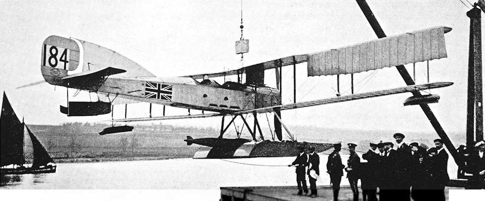
The original Short 184 in its earliest form with single-acting ailerons on the upper mainplane only.
The launching of the original Short Admiralty Type 184, No 184, at Rochester in March 1915, with a 14in torpedo in position between the floats.
The launching of the original Short Admiralty Type 184, No 184, at Rochester in March 1915, with a 14in torpedo in position between the floats.
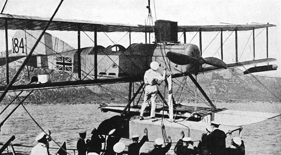
Short Seaplane No. 184 aboard H.M.S. Ben-my-Chree during the Dardanelles campaign. The aeroplane here has double-acting ailerons on upper and lower wings, and a plain rudder is fitted.
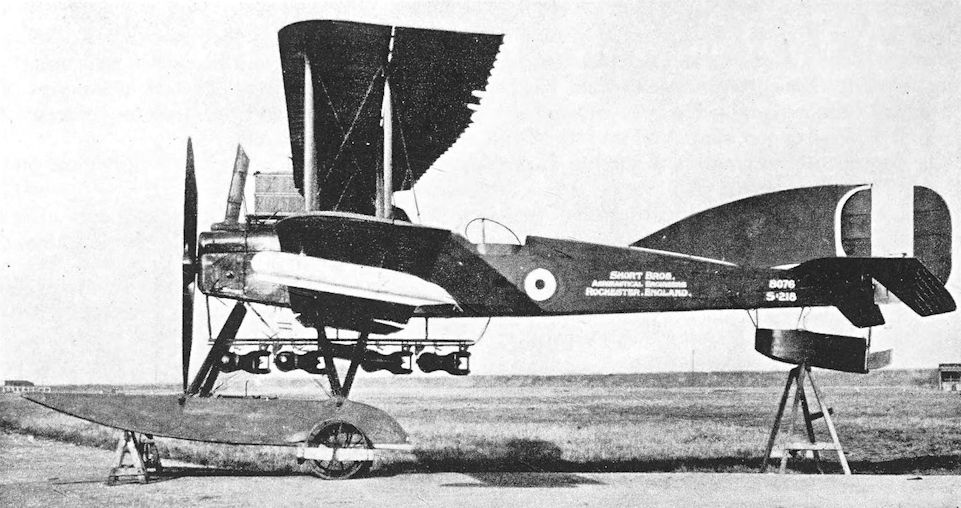
Standard production Short 184 with 240 h.p. Sunbeam engine. This illustration shows the method of carrying the bomb load.
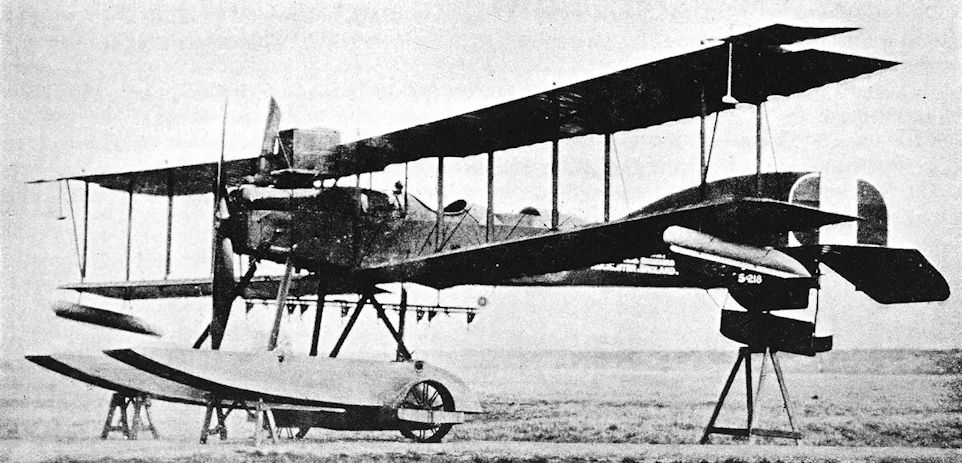
Short 184, No. 8076, fitted with Martin lateral stabilisers. Deflection of one of the forward surfaces at each wing-tip acted upon the ailerons in order to produce a righting force. The ailerons were horn-balanced.
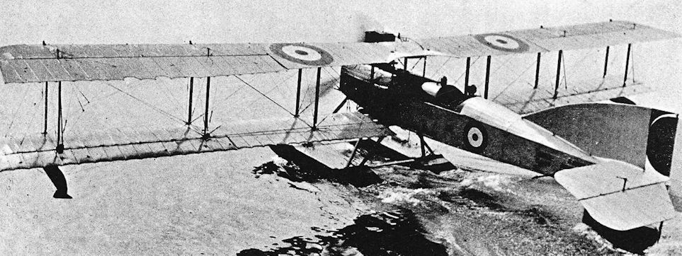
Short 184, Type D, serial number 8103.
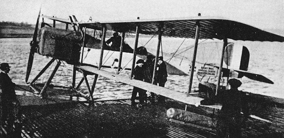
Short 184, serial number 8104, with Rolls-Royce Eagle engine.
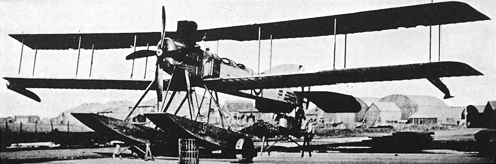
Short Seaplane, Admiralty Type 184, No. 8105 with high undercarriage.
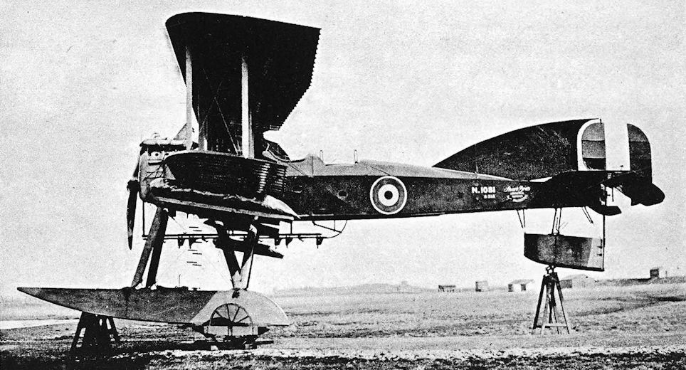
Short 184 with 240 h.p. Renault engine. Early installation with side radiators in Short-built aircraft N.1081.
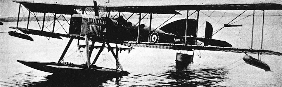
Dover type Short 184 with improved installation of 260 h.p. Sunbeam engine.
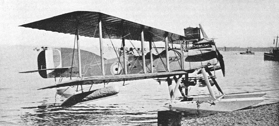
Saunders-built Short 184 with 240 h.p. Renault engine. Late installation with radiator above engine.
Sage-built Improved Type 184, N1616, powered by a 260hp Sunbeam engine, probably at Newlyn, seen with a pair of 100/ 112 lb bombs - often carried during coastal patrol sorties.
Sage-built Improved Type 184, N1616, powered by a 260hp Sunbeam engine, probably at Newlyn, seen with a pair of 100/ 112 lb bombs - often carried during coastal patrol sorties.
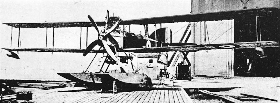
Short 184 with 260 h.p. Sunbeam engine.
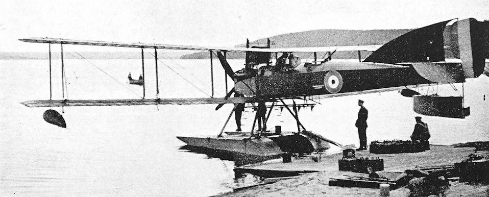
Short 184 with Sunbeam Maori III engine. Note the outside exhaust stacks.
Short 320
AS if to make a confusing system of aircraft nomenclature even more confusing, this Short seaplane was known by the numerical value of the horse-power of its engine. The power unit of most of the production machines was the Sunbeam Cossack of 320 h.p., but the early examples of the type had an earlier version of the engine which had a nominal output of 310 h.p. The Cossack was a water-cooled vee-twelve.
The new seaplane first appeared in 1916; it had been designed to fulfil official requirements for a long-range seaplane capable of carrying an 18-inch torpedo weighing 1,000 lb. (This was the new Mark IX torpedo, which contained 170 lb of T.N.T.)
The seaplane’s fuselage and tail-unit were typical of Short design, and a box-like radiator was perched on top of the engine. The wings were of unequal span and appeared to be similar to those of the modified Short 184 built by Mann, Egerton & Co., as the Mann, Egerton Type B; but the inversely tapered ailerons of the Short 320 had straight trailing edges, and the bracing of the upper-wing extensions was slightly different.
The float undercarriage, although apparently conventional, had been specially designed to permit the carrying and dropping of the torpedo. On the Short 320 the missile was carried roughly midway between the level of the floats and the bottom of the fuselage; the rear cross-bar of the floats was designed to be removable to give a clear passage for the dropping torpedo. Production machines had additional vee-struts from the rear float attachment points to the undersides of the lower wings. On the Short 320s which were not equipped with torpedo crutches, extra tankage and bomb racks were fitted, and the machines were used for long-range reconnaissance and anti-submarine patrol duties.
Rather oddly, the Short 320 was flown from the rear cockpit; it was, of course, flown without an observer when a torpedo was carried. Ordinarily the rearward position of the pilot would have meant that the observer had little hope of using a Lewis gun effectively, but the use of a somewhat desperate device gave the Short 320’s observer a reasonable field of fire. This consisted of a Scarff ring-mounting installed on a level with the centre-section; the ring-mounting was attached to the rear spar and was braced to the upper longerons of the fuselage by two struts. To fire the gun the observer was obliged to stand on the coaming of his cockpit.
The Short 320 was built in some numbers by Short Brothers and by the Sunbeam Motor Car Company, but production was on a small scale in comparison with that of the Short 184. The type was issued to various seaplane stations at home and in the Mediterranean.
In December, 1916, Commodore Murray F. Sueter, ever the protagonist of torpedo-carrying aircraft, submitted proposals for torpedo attacks on the German fleet at Wilhelmshaven and the Austrian fleet at Pola. The latter target held out greater chances of immediate success and was approved in January 1917; at the same time orders were placed for twenty-five Short 320s. In February the establishment of the R.N.A.S. Seaplane Station at Otranto was defined: it included twelve Short 320s.
The first attempt to use the big Shorts against the enemy was begun on September and, 1917, but proved unsuccessful. The objectives were enemy submarines lying in the Straits of Kumbor off Cattaro. Six Short 320s were placed on special rafts and were towed by motor launches to a point 50 miles south of Traste Bay, where the Shorts were to take off for Cattaro: this was done because the torpedo-laden Shorts could not lift enough fuel for the complete return flight from their base. At 4 a.m. on September 3rd the seaplanes were ready to start when the wind suddenly and unexpectedly increased to gale force and the sea became too rough for the machines to take off. Two pilots made unsuccessful attempts to get their Shorts into the air, but the attack had to be abandoned. One of the seaplanes sank on the way back to Otranto, and all the others were damaged.
The operation was never repeated, but it gave some indication of what could be done, and the Admiralty ultimately sanctioned an increase in the establishment of the R.N.A.S. bases at Otranto and Taranto.
By the beginning of 1918, very few torpedo attacks had actually been made by aircraft, and it was felt that there was insufficient information available concerning the behaviour of torpedoes launched from aircraft. Experiments were therefore conducted at Calshot in February, 1918. Four Short 320s were used, and between them released forty torpedoes fitted with dummy heads. The results were regarded as excellent: only three of the forty torpedoes were lost.
The Short 320 remained in service until the Armistice and for a short time thereafter. In 1919 the Imperial Japanese Navy had at least one machine of the type on its strength. It is known that N.1485 was sent to Japan.
SPECIFICATION
Manufacturers: Short Brothers, Rochester.
Other Contractors: The Sunbeam Motor Car Co., Ltd., Wolverhampton.
Power: 310 h.p. Sunbeam Cossack (maximum output 320 h.p. at 2,000 r.p.m.); 320 h.p. Sunbeam Cossack (maximum output 345 h.p. at 2,000 r.p.m.).
Dimensions: Span: upper 75 ft, lower 46 ft 9 1/2 in. Length: 45 ft 9 in. Height: 17 ft 6 in. Chord: 7 ft. Gap: 7 ft 2 in. Stagger: 5 1/2 in. Dihedral: 3. Incidence: 3. Span of tail: 21 ft. Distance between float centres: 14 ft 3 in.
Areas: Wings: upper 530 sq ft, lower 280 sq ft, total 810 sq ft. Ailerons: each 43-5 sq ft, total 87 sq ft. Tailplane: 75-5 sq ft. Elevators: 54-5 sq ft. Fin: 26 sq ft. Rudder: 26 sq ft.
Armament: One Lewis machine-gun on elevated Scarff ring-mounting fitted above forward cockpit and level with the centre-section. One 18-inch Mark IX torpedo (1,000 lb) carried beneath the fuselage, or two 230-lb bombs.
Service Use: R.N.A.S. Stations at Calshot, Felixstowe, Killingholme, Great Yarmouth and Isle of Grain. Mediterranean: R.N.A.S. 6th Wing, from bases at Otranto and Brindisi. R.N.A.S. Station, Calafrana, Malta, for anti-submarine patrols. Two Short 320s were used at the R.N.A.S. Torpedo School, Malta.
Production and Allocation: Serial numbers indicate that at least 137 Short 320s were ordered. On October 31st, 1918, the R.A.F. had fifty machines of the type on charge. Seventeen were at home seaplane stations, two were at other home bases, one was en route to the Middle East, and thirty were in the Mediterranean.
Weights {lb) and Performance:
Engine 310 h.p. Sunbeam 320 h.p.Sunbeam
Load Torpedo Torpedo Fuel for 6 hours and two 230-lb bombs
Date of Trial Report April 13 th, 1917 September 6th, 1917 September 25th, 1917
Type of airscrew used on trial - R.1708 -
Weight empty 4,873 4,933 4,891
Military load 1,175 1,273 690
Crew 360 360 360
Fuel and oil 605 448 1,080
Weight loaded 7,013 7,014 7,021
Maximum speed (m.p.h.) at
1,200 ft - 72-5 -
2,000 ft 77 - 79
6,500 ft - - 7'-5
m. s. m. s. m. s.
Climb to
2,000 ft 11 50 12 00 8 35
6,500 ft - - - - 45 00
Service ceiling (feet) 3,500 3,000 5,500
Endurance (hours) 3 - 6
Serial Numbers: 8317-8318: prototypes built by Short Brothers. N.1150-N.1159: built by Short. N. 1300-N.1319: built by Short. N.1360-N.1389: built by Sunbeam. N. 1390-1409: built by Short. N.1480-N.1504: built by Short. N.1690-N.1709: built by Sunbeam.
Notes on Individual Machines: N.1383: R.N.A.S. Station, Killingholme. N.1485: sent to Japan. N.1491 and N.1493 were used at the R.N.A.S. Station, Calafrana, Malta.
Costs: Airframe without engine, instruments and armament £3,589 7s.
Short 310 h.p. Seaplane, Type B: the North Sea Scout
CONTEMPORARY with the prototypes of the torpedo-carrying seaplane which became known as the Short 320 was another machine, similarly powered by the 310 h.p. Sunbeam Cossack engine. To distinguish it from the first type, the other aircraft was known as the Short 310 h.p. Seaplane, Type B, a somewhat cumbersome designation which may have suggested that a name of some kind was needed. However that may be, the Type B seaplane was also called the North Sea Scout.
Superficially the Type B resembled the Short 184, but it was in fact quite a different aeroplane. It was a three-bay biplane with wings of equal span, and the wings provided the principal distinguishing features of the type. Whereas the upper mainplane of the Short 184 had slight inverse taper which continued some way along the ailerons, the upper wing of the Type B was of constant chord, and its ailerons alone had an inverse taper on a straight trailing edge. The ailerons each had three control horns as opposed to the two which were fitted to the 184, and the centre-section of the Type B was not covered. The rear float attachment was made by a sturdy vee-strut, whereas the Short 184 had two single struts attached to opposite sides of each float. The fuselage of the Type B was deeper than that of the Short 184 and the pilot’s cockpit had a much closer coaming about it. The observer/gunner sat a short way farther aft. The aircraft’s principal weapon was a five-pounder Davis gun, but a Lewis gun was also provided for the seaplane’s own defence. The Davis gun could be mounted to fire upwards at an acute angle, indicating possible employment as an anti-airship machine; but its potentialities as an anti-submarine aircraft were considerable.
Although such hopes were built upon the Davis gun and production of the weapon was begun, it fell from favour. With its demise most of the aircraft which had been armed with it lost their designed purpose. The Short North Sea Scout was one of these.
SPECIFICATION
Manufacturers: Short Brothers, Rochester.
Power: 310 h.p. Sunbeam Cossack.
Armament: One five-pounder Davis recoilless gun and one Lewis machine-gun, both fired by the observer.
Serial Numbers: 8319-8320.

The first prototype Short Type 310A, S.299, No 8317, carrying a torpedo at Rochester in July 1916. The figure on the extreme right ts Oswald Short.

Production Short 320 with torpedo slung.

Production Short 320, long-range reconnaissance version

The first and only 310-B (Short 310 h.p. Seaplane, Type B), S.311 (8319) at Rochester in September 1916.
Short N.2B
THE last Short seaplane of the war period was the Type N.2B, fitted with the 275 h.p. Sunbeam Maori engine, which appeared on December 22nd, 1917. It was a two-bay biplane with extensions on the upper wing; the extensions were neatly braced by struts in place of the copious cable and king-post bracing which had been used on earlier types. Ailerons were fitted to the upper wing only, which had no dihedral; the lower wing was rigged with a marked dihedral angle.
The pilot sat under the centre-section, and the observer was situated several feet farther aft. The original design envisaged a radiator on the leading edge of the centre-section, but the N.2B appeared with a neat frontal radiator disposed round the airscrew shaft. The tail-unit was still of characteristic Short design, but the fin and rudder were of smaller area than those of the earlier Short two-seat patrol seaplanes with the exception of the S.364.
For the first time on a Short machine, the wing-tip floats were covered with mahogany and were attached directly to the spars of the lower wings; the earlier Shorts had all had simple fabric-covered canisters mounted on short struts below the wings.
The main floats of the first N.2B, which was numbered N.66, were single-step structures which had concave undersides; but when N.67 appeared it had conventional pontoon-type floats with flat-bottom surfaces. This second N.2B had a different radiator and slightly shorter ailerons; and its exhaust stack was canted over to starboard.
The N.2B was intended for service as a patrol bomber and had quite a good performance in its day. However, it seems to have appeared too late for development and production to be undertaken. The N.2Bs were not scrapped immediately the war ended, for N.67 gave Londoners a fine close-up of a Service seaplane on April 9th, 1919, when it landed on the Thames at Westminster. Its passenger was the Under Secretary of State for Air, General Seely, who had flown from Rochester in the aircraft.
SPECIFICATION
Manufacturers: Short Brothers, Rochester.
Power: 275 h.p. Sunbeam Maori.
Dimensions: Span: upper 55 ft 2 in. Length: 40 ft 2 in. Height: 13 ft 9 in. Chord: upper 7 ft 6in., lower 6 ft 6 in. Gap: maximum 7 ft. Span of tail: 15 ft 6 in. Airscrew diameter: 10 ft 6 in.
Weights (lb) and Performance:
No. of Trial Report N.M.119 N.M. 136
Date of Trial Report February 2nd, 1918 March 22nd, 1918
Type of airscrew used on trial A.B.716 -
Weight empty 3,119 3,280
Military load 659 673
Crew 360 360
Fuel and oil 603 598
Weight loaded 4,741 4,911
Maximum speed (m.p.h.) at
sea level - 92
2,000 ft 88 90
6,500 ft 86 88-5
10,000 ft 83-5 83-5
m. s. m. s.
Climb to
2,000 ft 5 25 4 50
6,500 ft 24 30 19 30
10,000 ft 69 00 40 35
Service ceiling (feet) 8,400 10,600
Endurance (hours) 4 1/2 -
Areas: Wings: 678 sq ft.
Tankage: Petrol: 70 gallons.
Armament: One Lewis machine-gun on Scarff ring-mounting on rear cockpit. Two 230-lb bombs on racks under the fuselage.
Production: It is believed that only two prototypes, N.66 and N.67, were built.
Serial Numbers: N.66-N.73.

Short N.2B. The first N.2B, N.66.

The second N.2B with flat-bottom pontoon-type floats.
Short S.364
THE Short seaplane which bore the works number S.364. was quite the neatest and cleanest seaplane built by Short Brothers during the 1914-18 war. It appeared in March, 1917, a two-bay equal-span biplane of rather small overall dimensions, powered by a 200 h.p. Sunbeam engine. The wings had finely-shaped elliptical tips and were designed to fold; they had a rigid trailing edge in place of the wire which had been used on earlier Shorts, and therefore did not have the characteristic scalloped appearance. The tail-unit was much smaller than that of any Short seaplane since the S.41.
The fuselage was a simple box structure with a rounded top-decking; the pilot sat under the centresection and the observer’s cockpit, surmounted by a Scarff ring-mounting, was some considerable distance farther aft. An experimental aerofoil section, designed to Admiralty Specification B.I.R.31, was used.
The S.364 was probably designed for use from light cruisers and other vessels not equipped for carrying aircraft. The fact that it was not developed further may have been due to the successful use of landplanes such as the Sopwith Pup for shipboard flying.
SPECIFICATION
Manufacturers: Short Brothers, Rochester.
Power: 200 h.p. Sunbeam Afridi.
Armament: One Lewis machine-gun on Scarff ring-mounting on the rear cockpit; two 65-lb bombs.
Serial Number: The serial number N.36 was allotted to a 200 h.p. Short seaplane, and was probably appropriate to the Short S.364.

This photograph, taken at the Isle of Grain (at Rochester ???), shows the Short S.364 with enlarged floats, but still powered by the 200hp Sunbeam Afridi engine.

Short S.364.
Short Shirl
THE Short Shirl was a single-engined torpedo-carrier which was contemporary with and directly comparable to the Blackburn Blackburd (see page 98). Like the Blackburd, the Shirl was intended to carry the Mark VIII torpedo containing 320 lb of T.N.T., and was designed for operation from aircraft carriers. The Shirl was powered by the Rolls-Royce Eagle VIII engine, and was a single-seater.
The fuselage was a conventional wooden structure consisting of four longerons and spacers, capped by a rounded top-decking; it was, however, covered with plywood. The tail-unit was similar to that of the Short N.2B seaplane. The 18-inch Mark VIII torpedo was carried in crutches close up against the underside of the fuselage.
The wings were of equal span but of unequal chord, and were arranged to fold. Conventional wooden spars and ribs were used, and the wings were fabric-covered; the trailing edges consisted of wire. Ailerons were fitted to upper and lower mainplanes.
The first Shirl, N.110, underwent its official tests at Martlesham in June, 1918. It was flown there by John Lankester-Parker, who had joined Short Brothers as chief test pilot in January, 1918.
The undercarriage on N.110 was a plain vee structure with a cross-axle, but that of the second machine, N.111, was an elaborate structure: it was divided to permit the easy dropping of the torpedo, and incorporated longitudinal skids. Each skid bore a pair of landing wheels. The second Shirl differed further from the first by having longer ailerons. On its first flight, N. 111 proved to be tail-heavy. The incidence of the tailplane was increased by four degrees, and a second test-flight was made during the afternoon of the same day. The machine was thereupon flown to the Torpedo Aeroplane School at East Fortune, which unit was responsible for training torpedo-plane pilots. It was flown at East Fortune in 1918, and carried out test torpedo-drops in the Firth of Forth.
The third Shirl, numbered N. 112, had a third form of undercarriage. This was again a divided structure with two wheels on each side but there were no long horizontal skids; inflatable bags were fitted on horizontal rails just above each pair of wheels and were intended for use as flotation gear if the aircraft were forced to alight on the water. The third Shirl had the longer ailerons.
Like the Blackburn Blackburd, the Shirl was found to be less satisfactory than the older Sopwith Cuckoo: it was slower and not sufficiently manoeuvrable to take the evasive action required after a close-range attack.
With the signing of the Armistice, development work on the Shirl ceased. The type had obvious potentialities as a load-carrier, however, and N.112 was fitted with a large cylindrical container for the transport of mails: the container was fitted in the position normally occupied by the torpedo. At a later stage a second cockpit was provided directly under the centre-section.
In 1919 Short Brothers produced a greatly modified Shirl with the intention of attempting the trans-Atlantic flight. This machine was a two-seater, fitted with an enormous fuel tank under the fuselage; the extended three-bay wings had a span of 62 ft 2 in. and an area of 1,015 sq ft, and a vee undercarriage was fitted. The Shirl's crew were Major J. C. P. Wood and Captain C. C. Wyllie, R.A.F., and the machine was the only one of the several trans-Atlantic contenders intended to attempt the crossing from east to west; its estimated range was 3,200 miles. Unfortunately, the Shirl came down in the Irish Sea while on its way to Ireland for the flight, and was lost.
SPECIFICATION
Manufacturers: Short Brothers, Rochester.
Power: 345 h.p. Rolls-Royce Eagle VIII; 360 h.p. Rolls-Royce Eagle VIII.
Dimensions: Span: 52 ft. Length: 35 ft. Height: 13 ft 3 in. Chord: upper 8 ft 6 in., lower 7 ft 6 in. Gap: 6 ft 6 in. Stagger: nil. Span of tail: 15 ft. Airscrew diameter: 10 ft.
Weights (lb) and Performance:
Engine 345 h.p. Eagle VIII 345 h.p. Eagle VIII 360 h.p. Eagle VIII 360 h.p. Eagle VIII
Load Without torpedo With torpedo With torpedo and 3 3/4 hours’ fuel Torpedo and 6 hours’ fuel
No. of Trial Report M.207 M.207 M.232 M.232
Date of Trial Report June, 1918 June, 1918 September, 1918 September, 1918
Type of airscrew used on trial S.239 S.239 - -
Weight empty 2,949 2,949 3,319 3,319
Military load 45 1,825 1,421 1,421
Pilot 180 180 180 180
Fuel and oil 558 558 592 1,031
Weight loaded 3,732 5,512 5,512 5,951
Maximum speed (m.p.h.) at
6,500 ft 98 94 93 92
10,000 ft 96-5 90-5 87 -
15,000 ft 93'5 - - -
m. s. m. s. m. s. m. s.
Climb to
6,500 ft 7 55 17 00 17 30 21 00
10,000 ft 14 00 38 00 38 25 - -
15,000 ft 27 20 - - - - - -
| Service ceiling (feet) 19,000 9,500 10,000 9,000
Endurance (hours) - - 3 3/4 6
Areas: Wings: 791 sq ft.
Tankage: Petrol: 137 gallons.
Armament: One 18-inch Mark VIII torpedo of 1,422 3/4 lb, carried in crutches under the fuselage.
Service Use: Tested at Martlesham and the Isle of Grain Experimental Station, and flown at the Aerial Fighting School (Torpedo Aeroplane School), East Fortune.
Production: Three prototypes were built.
Serial Numbers: N. 110-N. 112.
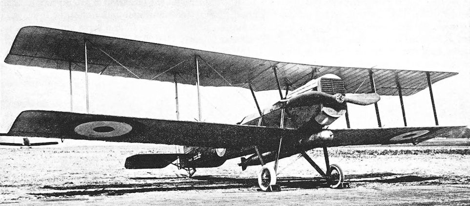
The first Short Shirl, N.110, with vee undercarriage.
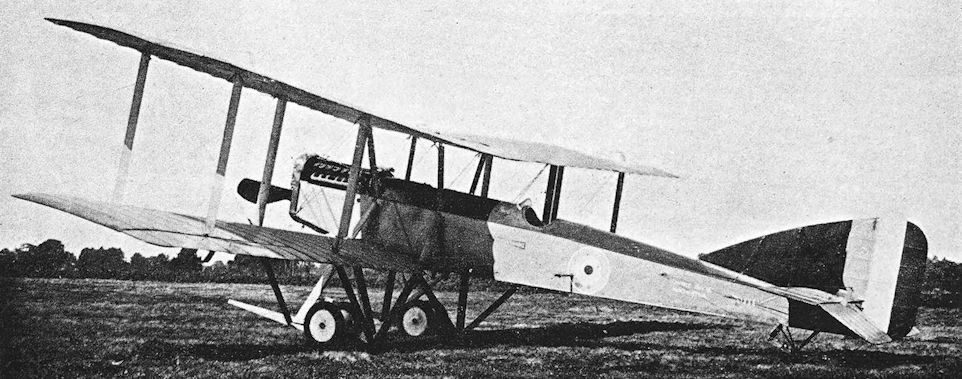
Short Shirl. The second machine, N.111, with divided undercarriage.

The third Shirl, N.112, converted to be a two-seater and fitted with mail container under the fuselage.
Siddeley Sinaia
THE design of the Sinaia was begun in the spring of 1918. It was a large twin-engined biplane of distinctive appearance, apparently intended for service as a bomber. In the disposition of its defensive armament the Sinaia struck an original note: the engine nacelles extended rearwards for a considerable distance, and a gunner’s cockpit was provided in the tail of each, quite six feet behind the trailing edges of the wings. Between them these two gunners covered the aircraft’s tail completely; but their positions, full in the slipstreams, must have made it well-nigh impossible for them to wield their Lewis guns.
A conventional fuselage was used. It terminated in a biplane tail-unit which had a small central fin and three rudders. Both upper and lower elevator surfaces were horn-balanced but did not move in parallel, indicating that one of them was a trimming surface.
The mainplanes were of unequal chord, and were arranged to fold. Upper and lower ailerons were horn-balanced; the balance areas were similar in shape to the corresponding surfaces on the third Siddeley R.T.1.
The engines for which the Sinaia was originally designed were two of the new (but now little-known) Siddeley Tigers. The Tiger was a liquid-cooled vee-twelve which developed 486 h.p. With Tiger engines the aircraft was designated Sinaia Mark I. Alternatively, it could be powered by two Rolls-Royce Condors: this was the Sinaia Mk. II. A Mark III version with two Beardmore Atlantics was envisaged, but had been abandoned by January, 1919. It appears that an installation of two Napier Lions was also contemplated.
Four prototypes were ordered, and the fuselage of the first was in course of assembly late in June, 1918. By that time an experimental forward fuselage portion had been made for tests with a Coventry Ordnance Works quick-firing gun.
With the Armistice, the need for economy and the absence of any urgency brought work virtually to a standstill; and it was not until June 25th, 1921, that the Sinaia first flew. The test flying was done by Captain Frank T. Courtney. Apparently the aeroplane was not developed, for neither it nor its Tiger engines were later heard of.
SPECIFICATION
Manufacturers: The Siddeley-Deasy Motor Car Co., Ltd., Park Side, Coventry.
Power: Sinaia Mk. I: two 486 h.p. Siddeley Tiger. Sinaia Mk. II: two 600 h.p. Rolls-Royce Condor. Sinaia Mk. Ill: two 500 h.p. B.H.P. (Galloway) Atlantic.
Dimensions: Span: 86 ft 10 in.
Areas: Wings: 1,823 sq. ft.
Weights: Loaded: 16,000 lb.
Armament: Gunners’ cockpits were situated in the nose of the fuselage and at the rear of each engine nacelle, and presumably each would have at least one Lewis machine-gun on a Scarff ring-mounting. Experiments were carried out with a Coventry Ordnance Works quick-firing gun.
Serial Numbers: J.6858-J.6859.

Siddeley Sinaia with Siddeley Tiger engines.
Siddeley R.T.1
ARISING out of Parliamentary criticisms of the administration of the Royal Flying Corps and the work of the Royal Aircraft Factory, a committee was set up under the chairmanship of Sir Richard Burbidge to inquire into the affairs of the Factory.
The committee was set up on May 12th, 1916, and issued its report in the following year. One of its chief recommendations was to the effect that the Factory should not engage in aircraft production, even of an experimental nature. The report was officially accepted: the acceptance ultimately resulted in a substantial reduction in the staff of the Factory and the release to industry of several of its most experienced members.
Among those who left was Major F. M. Green, who had been Chief Engineer at the Royal Aircraft Factory. In January 1917, he, with S. D. Heron and J. Lloyd, joined the Siddeley-Deasy Car Co., who were contractors for several types of aircraft. One of those types was the R.E.8, in the design of which Lloyd had had a considerable share.
The first product of the new Siddeley design team was a modification of the R.E.8, known as the Siddeley R.T.1. The R.T.1 embodied a number of R.E.8 components, and affords an interesting comparison with the Royal Aircraft Factory’s own R.E.9. The R.T.1s were, in fact, taken straight off the Siddeley production line, for they were the last airframes of the batch of R.E.8s originally ordered as B.6481-B.6630.
The first R.T.1 was B.6625, which had a 200 h.p. Hispano-Suiza engine cowled in a manner which closely resembled the installation in the S.E.5a; long horizontal exhaust pipes were fitted.
The fuselage was basically that of the R.E.8, but a deeper top-decking was fitted; this raised the observer’s gun-ring by some inches. The fin and rudder were larger than those of the R.E.8; the rudder was horn-balanced, and bore a strong resemblance to that of the R.E. 9.
But the greatest difference between the R.E.8 and the R.T.1 lay in the mainplanes. The wings of the R.T.1 were of equal span, with the upper of considerably greater chord than the lower; the new wing arrangement was adopted specifically to provide a stronger structure. There were two bays of interplane struts. Ailerons were fitted to upper and lower wings; the upper ailerons were attached to false spars fitted some way behind the rear main spar.
The second R.T.1, B.6626, bore the strongest resemblance to the R.E.8, because it was fitted with the 150 h.p. R.A.F. 4a engine in the standard R.E.8 installation. This version was tested in December, 1917. It was first flown without any gaps in the lower wing-roots, but these were later provided in order to improve the pilot’s downward vision.
Although the wing-span of the Siddeley R.T.1 was a foot less than that of the R.E.8, it yet looked like a larger aeroplane. It was intended to be a replacement for the R.E.8, for an official description states: “The type R.T.1 machine is the R.E.8 re-designed. Modifications have been made with the object of improving the machine generally, rather than bettering the performance.” The R.T.1’s armament was peculiar: the pilot had a Lewis gun mounted above the centre-section, firing forwards and upwards to clear the airscrew.
A third version of the design had a 200 h.p. Hispano-Suiza engine in a different form of cowling. The radiator was underslung, and the engine-cowling had a rounded nose rather like that of the D.H.9. Exhaust stacks like those of the R.E.8 were fitted, but were splayed outwards. This third machine had horn-balanced ailerons. An R.T.1 with a Hispano-Suiza engine was officially tested in March, 1919.
One of the R.T.1s was sent to France for Service trials in 1918. The type was not adopted, however, possibly because of the prospect of Bristol Fighters equipping the Corps Reconnaissance squadrons.
SPECIFICATION
Manufacturers: The Siddeley-Deasy Motor Car Co., Park Side, Coventry.
Power: 150 h.p. R.A.F. 4a; 200 h.p. Hispano-Suiza.
Dimensions: Span: 41 ft 9 in. Length: 27 ft 8 in. Height: 11 ft 7 in. Chord: upper 6 ft 6 in., lower 4 ft 9 in. Gap: 4 ft 8 1/2 in. Stagger: 2 ft 5 1/2 in. Dihedral: 3 30'. Incidence: 4 30'. Span of tail: 13 ft 1 in. Tyres: 700 X 100 mm.
Areas: Wings: 420 sq ft. Ailerons: total 68 sq ft. Tailplane: 24 sq ft. Elevators: 12 sq ft. Fin: 7 sq ft. Rudder: 11 sq ft.
Tankage: Petrol: 37 1/2 gallons. Oil: 51/2 gallons.
Armament: One fixed Lewis machine-gun mounted above the centre-section to starboard of centre, firing forwards and slightly upwards above the airscrew; one free Lewis gun on Scarff ring-mounting on rear cockpit.
Service Use: The R.T.1 numbered B.6625 was at Wyton, the aerodrome of No. 31 Training Squadron, in March, 1918.
Weights (lb) and Performance:
Version R.A.F. 4a engine without gap in lower wings R.A.F. 4a with gap 200 h.p.Hispano-Suiza engine
No. of Trial Report M.162 M.162 M.253
Date of Trial Report December, 1917 December, 1917 March, 1919
Type of airscrew used on trial T.6296 T.6296 T.28152
Weight empty 1,773 1,773 1,803
Military load 185 185 185
Crew 360 360 360
Fuel and oil 272 272 359
Weight loaded 2,590 2,590 2,707
Maximum speed (m.p.h.) at
6,500 ft 101 - -
10,000 ft 98-5 97-5 108
13,000 ft 94-5 93-5 -
15,000 ft 90-5 88-5 100
m. s. m. s. m. s.
Climb to
1,000 ft 1 20 1 35 - -
2,000 ft 2 50 3 15 - -
5,000 ft 7 45 9 00 - -
6,500 ft - - - - 10 35
8,000 ft 13 55 16 20
10,000 ft 19 10 22 30 18 30
12,000 ft 25 50 30 30 - -
15,000 ft 41 30 50 00 36 25
16,000 ft 50 10 - - - -
Service ceiling (feet) 16,000 15,000 18,000
Production and Allocation: Three R.T.1s were delivered to the R.F.C. One went to the B.E.F. in France in 1918: two went to training units, one in 1917 and the other in 1918.
Serial Numbers: B.6625-B.6630, ordered under Contract No. A.S.7903.
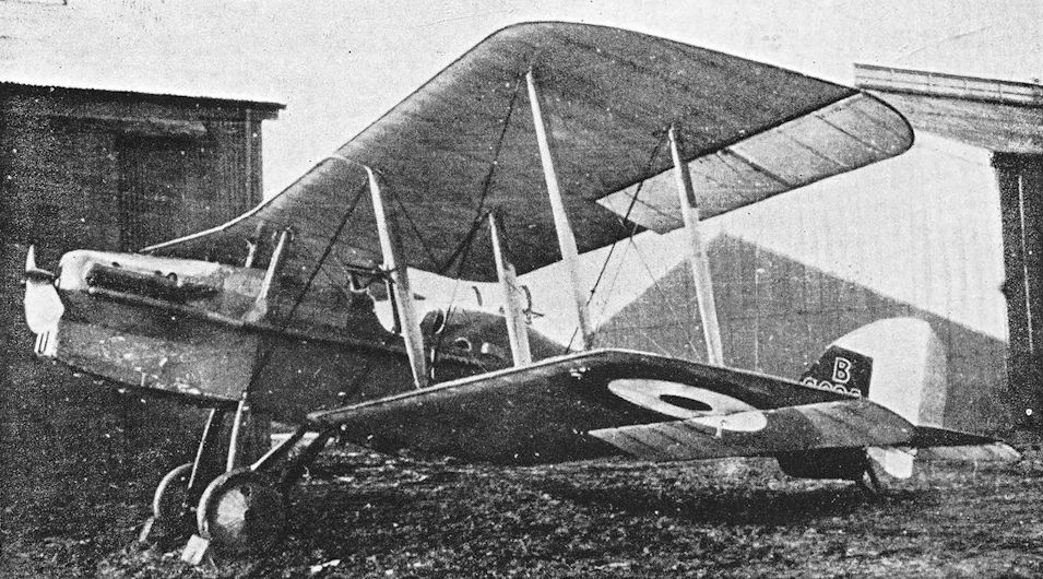
The first Siddeley R.T.1, B.6625, with 200 h.p. Hispano-Suiza engine.
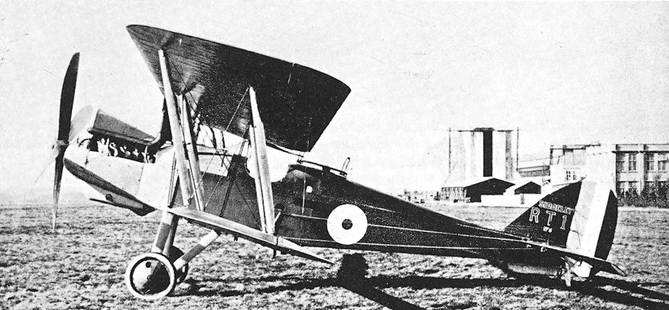
Siddeley R.T.1 with 150 h.p. R.A.F. 4a engine.
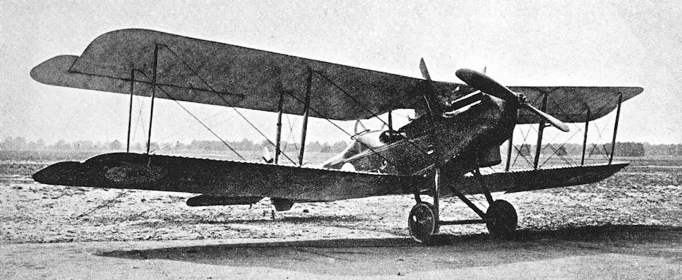
Siddeley R.T.1. The final form of the R.T.1, with 200 h.p. Hispano-Suiza engine, underslung radiator, and horn-balanced ailerons.
Sopwith Bat Boat No. 1
T.O.M. (LATER SIR THOMAS) SOPWITH acquired a reputation in the aeronautical world at an early date. On December 18th, 1910, he won the £4,000 Baron de Forest prize for the longest flight from England to the Continent. Flying his Howard Wright biplane, he covered a distance of 169 miles from Eastchurch. He had received his R.Ae.C. Aviator’s Certificate (No. 31) a little over three weeks earlier.
Mr Sopwith founded the Sopwith Aviation Company in 1912. Two aeroplanes were built in that year: the first was a modified Wright biplane, the second a rather makeshift tractor biplane which had Wright wings, Farman undercarriage, and an original fuselage and tail unit.
The year 1913 marked the beginning of that true greatness which was to distinguish the Sopwith company and its products. At the Aero Show which was held at Olympia in February, 1913, two Sopwith aircraft were shown. Both were excellent machines, but the more striking and original of the two was a two-seat “hydro-biplane”; an aircraft of a class which was to become known as the flying boat.
Although preceded in point of time by the Curtiss flying boat, the Sopwith machine was the first truly practical British flying boat; it was later known as the Bat Boat. It was essentially a very simple aircraft.
The hull, which weighed only 180 lb, was a beautiful hydroplane built in wood by S. E. Saunders of Cowes; it was 20 feet long and 4 feet in the beam. Sam Saunders had had previous experience of making high-speed hulls, for he had contributed to the construction of the remarkable Revaud hydroplane in 1909. The hull of the Bat Boat had exemplary simplicity of line and was covered with special plywood patented by Saunders under the name “Consuta”. This plywood was sewn with copper wire around the edges and at six-inch intervals to prevent veneer separation. The Bat Boat hull had two layers of cedar planking sewn together by this method. As shown at Olympia, the machine had a forward elevator mounted on the prow of the hull.
To this elegant hull was added a simple two-bay biplane structure with a 90 h.p. Austro-Daimler engine mounted amidships, raised above the hull by struts and driving a pusher airscrew. Tail-booms supported a monoplane tailplane and elevator, and a single plain rudder was fitted: the tail-booms converged to meet at the axis about which the rudder pivoted.
The Bat Boat made an excellent impression at the Aero Show, and the type was purchased by the Admiralty for the use of the Naval Wing of the R.F.C. It was flown from Calshot, where it performed some valuable experimental work. The forward elevator was removed at an early stage, and the original plain rudder was replaced by an enlarged surface with a horn-balance area at either end.
The achievement for which the early Bat Boat is best remembered is its success in winning the Mortimer Singer prize for the first all-British amphibious aircraft to fulfil the difficult requirements which had been laid down. These called for six out-and-home flights between two points five miles apart, one point on land and the other on water: thus six landings and take-offs had to be made from land and six from water. Each flight was to be made at a height not lower than 750 feet, and on one of the flights a height of 1,500 feet had to be reached; the whole series of flights was to be completed in five hours.
By fitting the Bat Boat with a 100 h.p. Green engine, Mr Sopwith brought it into the all-British category; and a movable wheel undercarriage was fitted: this consisted of two wheels, one on each side of the hull, which could be lowered to enable the boat to alight on land and raised again when the machine had to come down on water. By this time the tail-unit had been modified again. Twin rudders were fitted, and were wholly below the level of the tailplane and elevator; this last surface was in one piece instead of being divided, as was originally the case. The tail-boom structure was modified to accommodate the two rudders.
On July 8th, 1913, Mr. H. G. Hawker, accompanied by Lieutenant Spenser D. A. Grey as official observer, successfully completed the tests in 3 hours 25 minutes and won the prize of L500. Lieutenant Grey’s hazardous contribution to Hawker’s success consisted of kicking the wheels down before each landing at Hamble, for they failed to drop when released after each take-off from the Solent.
In Naval service, the Bat Boat was flown a good deal by Lieutenant A. W. Bigsworth and Sub-Lieutenant J. L. Travers. These two officers used the machine in early experiments to determine the behaviour of missiles dropped from aircraft. The results of these experiments provided the R.N.A.S. with data for the development of bomb-aiming.
The Bat Boat was flown at the Royal Naval Review in July, 1914. On the 17th of that month Flight Commander J. L. Travers had flown over the assembled Fleet by night. Previously, this officer had flown the Bat Boat with a small searchlight mounted in the bows. At this time (summer 1914) the vertical tail area was increased by the addition of a simple triangular fin in front of each rudder, and the power unit was the go h.p. Austro-Daimler engine.
When war broke out, the Bat Boat was sent to the seaplane station at Scapa Flow. Patrols over the Fleet began on August 24th, 1914, and were maintained daily until November 21st, when a gale wrecked all the aircraft and hangars at the station. The Sopwith Bat Boat was not officially written off until March, 1915, however.
SPECIFICATION
Manufacturers: The Sopwith Aviation Company, Ltd., Canbury Park Road, Kingston-on-Thames. Hull made by S. E. Saunders, Cowes, Isle of Wight.
Power: 90 h.p. Austro-Daimler; 100 h.p. Green.
Dimensions: Span: 41 ft. Length: 32 ft.
Areas: Wings: 422 sq ft.
Weights: Empty: 1,200 lb. Loaded: 1,700 lb.
Performance: Maximum speed: 65 m.p.h.
Armament: None.
Service Use: Flown at seaplane stations at Calshot and Scapa Flow.
Serial Number: 118.
Sopwith Bat Boat No. 2
A NEW Sopwith flying boat was displayed at the 1914 Aero Show which opened at Olympia on March 16th. In general layout the new machine resembled the Bat Boat of the previous year but was considerably larger and more powerful: its engine was a 200 h.p. Salmson radial. The new flying boat was unofficially called the Bat Boat No. 2; it was a two-seater with side-by-side seating for its crew.
The entire aircraft, including the hull, was made at the Sopwith factory at Kingston-on-Thames. The single-step hull was built up of two skins of mahogany on a framework of ash stringers; and the central interplane struts, which also supported the Salmson engine and its radiator, were of ash. The engine could be started from the cockpit by means of two compressed-air starters fitted under the seats. The mainplanes had three bays of spruce struts and there were strut-braced extensions on the upper wings. The spruce tail-booms converged in plan towards the axis of the single oval rudder, and the tailplane and elevators were attached to the upper tail-booms.
One of the most interesting features of the larger Bat Boat was the use of an auxiliary power-plant to provide power for a wireless transmitter: a motor-cycle engine was installed in front of the passenger’s seat.
This excellent flying boat was ordered by the German government after the Olympia show, and one was delivered before the outbreak of war. It was used by the German Naval Air Service in the Baltic.
A modified Bat Boat No. 2 was built for the 1914 Daily Mail “Round Britain” contest. This Bat Boat had a 200 h.p. Sunbeam engine in place of the original Salmson, and the lower wings were raised a little above the hull. It was to have been flown by Howard Pixton, but the outbreak of war led to the cancellation of the contest.
SPECIFICATION
Manufacturers: The Sopwith Aviation Co., Ltd., Canbury Park Road, Kingston-on-Thames.
Power: 200 h.p. Salmson (Canton-Unne); 200 h.p. Sunbeam.
Dimensions: Span: upper 55 ft, lower 45 ft. Chord: 6 ft 9 in. Gap: 7 ft.
Areas: Wings: 600 sq ft.
Weights: Empty: 2,300 lb. Loaded: 3,180 lb.
Performance: Maximum speed: 70 m.p.h. with Salmson, 75 m.p.h. with Sunbeam. Endurance: 4 1/2 hours with Salmson, 5 hours with Sunbeam.
Tankage: Petrol: 70 gallons. Oil: 7 gallons.
Service Use: Used by the German Naval Air Service.
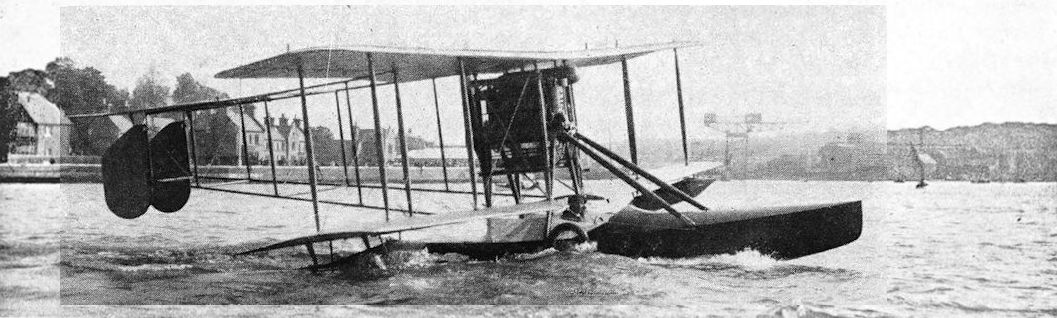
Bat Boat 1 with twin rudders and movable wheels - or retractable landing gear. Harry Hawker in cockpit.
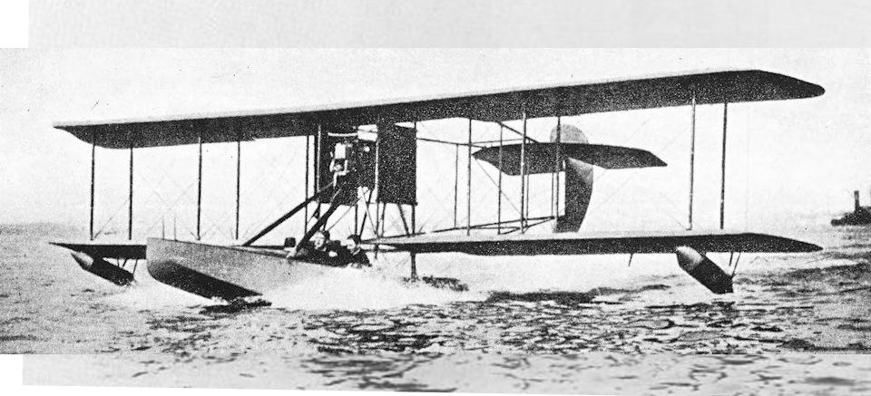
Sopwith Bat Boat BB.2 as first built in mid 1913.
The Bat Boat I (with single rudder, and no bow-mounted elevator) was a new sight for British eyes.
The Bat Boat I (with single rudder, and no bow-mounted elevator) was a new sight for British eyes.
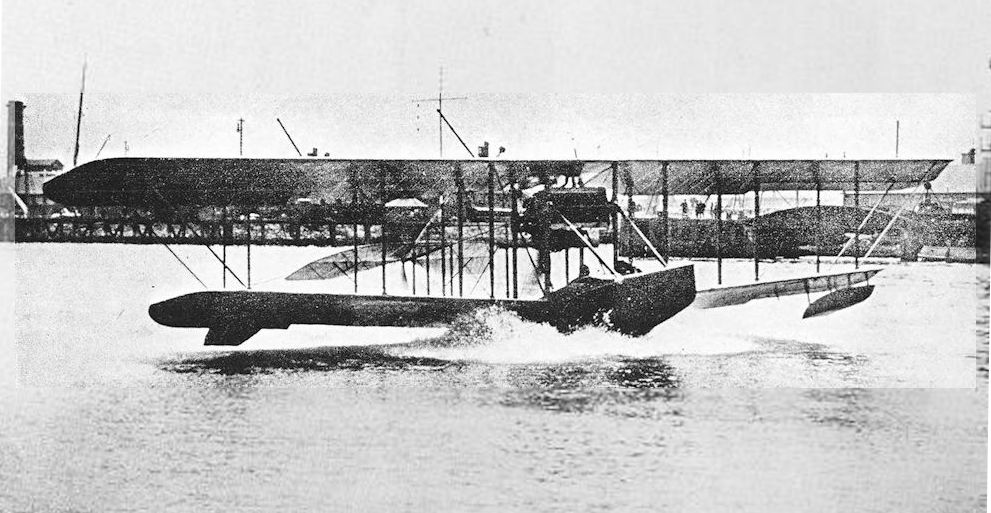
The Circuit Bat Boat (Type 2) BBS was impressed in August 1914 as RNAS No.879.
Sopwith Seaplane, Admiralty Type 137
PERHAPS the least-known of all the Sopwith types is this seaplane which had the official serial number 137. It was a comparatively small two-seater with two-bay wings of unequal span; the wings did not fold. The engine was a 120 h.p. Austro-Daimler, and had a flat frontal radiator.
The fuselage, wings and tail-unit were all typical of contemporary Sopwith practice. Large single-step floats of the pontoon type were fitted, and there was a tail-float to which a water-rudder was hinged.
The designed purpose of the machine is uncertain. It was probably intended to be a patrol seaplane, but may have been used as a trainer. It was still in service in 1915, when it was overhauled by Pemberton-Billing Ltd., at Woolston, Southampton.
The serial numbers 137 and 138 were allotted for Sopwith seaplanes. It is believed that No. 138 had a 200 h.p. Salmson engine, but the aircraft type is uncertain.

A puzzling machine from many aspects was the Sopwith seaplane shown here, which bore the Admiralty type-number 137 and was powered by a 120 hp Austro-Daimler engine.
Sopwith Admiralty Type 137 seaplane, assembled at Woolston in 1914, had an Austro Daimler engine.
Sopwith Admiralty Type 137 seaplane, assembled at Woolston in 1914, had an Austro Daimler engine.
Sopwith Seaplane (100 h.p. Anzani)
IN July, 1913, the Naval Wing of the R.F.C. took delivery of the first example of a Sopwith seaplane of a new type. This new Sopwith design was a two-seat tractor biplane of conventional but workmanlike appearance, powered by a 100 h.p. Anzani ten-cylinder radial engine.
The fuselage and tail-unit resembled those of the Sopwith three-seat landplane, and the undercarriage consisted of two main single-step floats and a tail-float: a structural peculiarity was the attachment of the floats to the lower wings instead of to the fuselage. The floats were made of wood; each had five watertight compartments, all with watertight inspection doors. The wings had three bays of bracing, and extensions were fitted to the upper mainplanes; ailerons were fitted to both upper and lower wings.
The three seaplanes of this type which were delivered to the Naval Wing were numbered 58 to 60 inclusive. No. 59 went to Cromarty seaplane station, and took part in the Naval Manoeuvres of 1913; whilst No. 60 went to Great Yarmouth.
The Cromarty machine was crashed in the autumn of 1913 by Lieutenant Oliver. It seems probable that two of the original three survived until August, 1914, for it is recorded that the R.N.A.S. had two Sopwith Anzani seaplanes on its strength when war broke out.
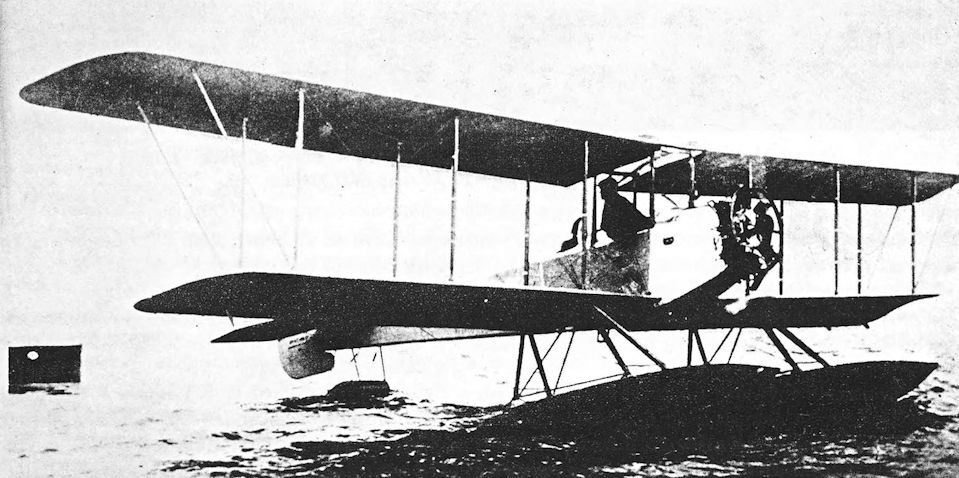
Sopwith Seaplane (100 h.p. Anzani).
Sopwith Tabloid
THE Sopwith Tabloid made a dramatic debut at Hendon on November 29th, 1913. On that day it had undergone official trials at Farnborough, where it had returned performance figures which at that time were astonishing. The machine’s performance was regarded as the more remarkable because it was a biplane: it was generally believed that the monoplane was the superior form of aeroplane.
The Tabloid was designed and built in considerable secrecy. It was intended to be used for demonstration flying and racing, and was remarkably compact. The original Tabloid was a two-seater; pilot and passenger sat side-by-side in the single cockpit. The engine was an 80 h.p. Gnome, and was almost wholly enclosed in the peculiar cowling. Cooling air was admitted through two slots in the front bearing member of the fore-and-aft engine mounting. Construction was of wood throughout; the fuselage was a wire-braced box girder with a rounded top-decking. The undercarriage was a simple twin-skid structure.
The wings had only a single pair of interplane struts on each side. Lateral control was by wing-warping. The semicircular tailplane was fitted with divided elevators, and a balanced rudder of rounded outline was hinged to the sternpost; there was no fin. The Tabloid’s first flights were made at Brooklands, and on their successful completion Hawker flew the machine to Farnborough. The official tests showed that the Tabloid had a speed of 92 m.p.h. and climbed to 1,200 feet in one minute with pilot, passenger and fuel for 2 1/2 hours. Hawker gave the Hendon crowds startling evidence of the Tabloid’s speed by flying two laps of the racing course at maximum speed.
Hawker took the prototype Tabloid to Australia, his native land, early in 1914; there he gave demonstration flights. He returned on June 6th, 1914, by which time the Tabloid had been fitted with a simple vee undercarriage and the rear fuselage had been stripped of its fabric covering.
During Hawker’s absence other Tabloids had been built. The most noteworthy was the machine which, fitted with a float undercarriage and a 100 h.p. Gnome Monosoupape engine, won the Schneider Trophy for Britain on April 20th, 1914. A modified vertical tail assembly was fitted: there was a triangular fin with a plain rudder hinged to it. This particular aeroplane is discussed in the history of the Sopwith Schneider and Baby seaplanes.
Soon after the Schneider contest, the racing seaplane was converted to a landplane; the undercarriage was a simple vee structure. In this form the machine was flown in the 1914 Aerial Derby. Its pilot was R. H. Barnwell, but he was unable to exploit his aircraft’s performance to the full owing to the bad visibility; ultimately he had to abandon the race.
The Tabloid went into small-scale production for the R.F.C. and R.N.A.S. early in 1914, and by June 5th, 1914, six machines had been completed. The production Tabloids were all single-seaters, and all had a fin and rudder similar to those of the Schneider seaplane. The skid-type undercarriage was fitted; the forward struts were more sharply raked than those of the prototype, and some machines had an additional strut in the skid bracing. The engine was the 80 h.p. Gnome.
The Tabloid has frequently been described as the first single-seat scout ever built. That is not historically accurate, for it was preceded by the Royal Aircraft Factory’s B.S.1 by several months. It was, however, used for scouting duties in the early months of the war. Four went to France with the Aircraft Park which arrived at Boulogne on August 18th, 1914. Two of these Tabloids were flown for scouting purposes by Lieutenant Norman Spratt and Lieutenant Gordon Bell: they were unarmed. To chase a German aeroplane on one occasion, Norman Spratt took some flechettes (steel darts) in his Tabloid, and is said to have forced the enemy machine down by circling round it. Squadrons Nos. 3 and 4 each had a Tabloid on their strength for a short time.
The Tabloid was not generally popular when it was first introduced into the Service, and it acquired a reputation for being a rather dangerous aeroplane. Rumour, as usual, was false: the trouble lay in the pilots themselves, for flying technique had not advanced in step with the improvements in aircraft design.
The R.N.A.S. had one Tabloid when war broke out, but it was intended to send two to join Commander Samson’s Eastchurch Squadron at Antwerp at the earliest possible date. By early October, 1914, they had arrived, but the British force had to evacuate Antwerp on the 7th of the month. The two Tabloids, numbered 167 and 168, were the last aeroplanes to leave Antwerp; their pilots were Squadron Commander Spenser Grey and Flight Lieutenant R. L. G. Marix, who had orders to bomb the Zeppelin sheds at Cologne and Dusseldorf. Bad visibility delayed their take-off until 1.20 p.m. on October 8th.
Thick mist prevented Spenser Grey from finding his objective, and he had to be content with dropping his bombs on Cologne railway station. Marix, flying No. 168, was more fortunate: he dropped his bombs from a height of 600 feet above the airship shed at Dusseldorf and was rewarded by a great explosion accompanied by flames 500 feet high. He had destroyed a brand-new Zeppelin, the Z.IX. Marix’ Tabloid was damaged by ground fire, but he managed to get to within 20 miles of Antwerp before he was obliged to land; he completed his journey by bicycle, and escaped from Antwerp by motor. Spenser Grey returned to Antwerp, but his Tabloid was damaged by enemy shell-fire: he too left for Ostend by motor.
There was no standard armament installation on the Tabloid, but in February, 1915, the Tabloids of Commander Samson’s squadron were fitted with a mounting for a Lewis gun above the upper wing. The mounting was devised by Warrant Officer J. G. Brownridge and Lieutenant T. Warner.
Two Tabloids accompanied Commander Samson’s squadron to the Dardanelles in March, 1915, but proved to be of little real use there. They were not the first machines of their type to reach that theatre of war, however, for they had been preceded by the two Tabloids which were the only landplanes included in the equipment of the aircraft carrier Ark Royal: the carrier arrived at Tenedos on February 17th, 1915. There was then no aerodrome on Tenedos, so the Tabloids were of no immediate use; nor is there any record of their use once the aerodrome - an area of 600 yards by 300 yards - was prepared.
Production of Tabloids ended in the spring of 1915, and the type vanished from the operational scene. A few went to training units. The last major modification was the fitting of ailerons to the late production machines.
At least one R.N.A.S. Tabloid was fitted with a Lewis gun arranged to fire forward through the airscrew; there was no interrupter gear, but the airscrew was fitted with steel deflector plates to protect it from damage by bullets which did not pass between the blades. The gun was mounted on the starboard side of the fuselage just below the upper longeron. The Tabloid which had this experimental installation was fitted with a simple vee undercarriage and had large wing-tip skids.
SPECIFICATION
Manufacturers: The Sopwith Aviation Co., Ltd., Canbury Park Road, Kingston-on-Thames.
Power: Standard: 80 h.p. Gnome. Racing version: 100 h.p. Gnome Monosoupape.
Dimensions: Span: 25 ft 6 in. Length: prototype, 20 ft; production version, 20 ft 4 in. Height: 8 ft 5 in. Chord: 5 ft 1 1/2 in. Gap: 4 ft 6 in. Stagger: 11 in. Dihedral: 1° 30'. Incidence: 1°. Span of tail: 9 ft 6 in. Airscrew diameter: 8 ft 2 in. Wheel track: 4 ft 9 in.
Areas: Wings: upper 128-3 sq ft, lower 113sq ft, total 241-3 sq ft. Ailerons (late production Tabloids only): 28 sq ft. Tailplane: 11-8 sq ft. Elevators: 11-8 sq ft. Fin: prototype, nil; production version, 1-8 sq ft. Rudder: prototype, 7 sq ft; production, 4-27 sq ft.
Weights: Prototype: Empty, 670 lb. Loaded: 1,060 lb. Production: Empty, 730 lb. Loaded: 1,120 lb.
Performance: Maximum speed at ground level: 92 m.p.h. Climb to 1,200 ft: 1 min. Endurance: 3 1/2 hours.
Armament: Various experimental installations of single Lewis machine-guns, above the centre-section or on starboard side of fuselage, firing forward. A small load of 20-lb bombs could be carried.
Service Use: Western Front: R.F.C. Squadrons Nos. 3, 4 and 7; R.N.A.S., Eastchurch Squadron operating from Antwerp. Dardanelles: No. 3 Squadron, R.N.A.S., Tenedos; aircraft carrier H.M.S. Ark Royal. R.N.A.S. units in Britain: No. 1 Squadron, R.N.A.S., Gosport; R.N.A.S. Station, Great Yarmouth.
Production and Allocation: A small number of Tabloids were built before the outbreak of war, and thirty-six were built between October 1st, 1914, and June 30th, 1915. Four went to France with the Aircraft Park in August, 1914, and one went there in 1915. Training units received four in 1914 and one in 1915. A total of at least four were delivered to Commander Samson’s R.N.A.S. Squadron; and two went to the Dardanelles aboard H.M.S. Ark Royal.
Serial Numbers: 123, 124, 167-169, 326, 394, 1201-1213.
Notes on Individual Machines: 167 and 168 were allocated to the R.N.A.S. Squadron operating from Antwerp in October, 1914; they bombed Cologne and Dusseldorf on October 8th, 1914. 1208: R.N.A.S. Station, Great Yarmouth.

A simple V-type landing gear and stripped rear fuselage gave a distinctive appearance to the modified version of the first Tabloid that Harry Hawker demonstrated in Australia, and seen here after its return.

This view of the first Sopwith Tabloid at Hendon shows to advantage its relatively wide cockpit, seating two side-by-side. When it first appeared, in November 1913, it impressed everyone with its sprightly performance, and soon won orders from the military.

At first glance, Tabloids Nos. 326 and 394 were seemingly identical; but scrutiny of the wheel/skid landing gear proves otherwise the latter having extra struts (or a V-type gear plus skids).
Sopwith Tractor Biplane (80 h.p. Gnome)
THE first Bat Boat shared the Sopwith stand at the 1913 Aero Show with a handsome and workmanlike tractor biplane, powered by an 80 h.p. Gnome rotary engine. In its display form this Sopwith machine had seats for the pilot, who occupied the rear cockpit, and two passengers who sat side-by-side in front. Three large transparent panels let into each side of the fuselage ensured good downward view for all occupants.
The engine was installed in a nose-bearing mounting and was simply and effectively cowled. The undercarriage was a sturdy affair, with horizontal skids each of which had a small auxiliary wheel at its forward end. An unusual design feature was the use of twin tail-skids.
The two-bay wings had slight stagger and were braced by cables. Lateral control was by wing-warping. A semicircular tailplane with divided elevators was fitted, and an oval rudder was used; its axis was slightly set back in order to provide a small balancing area. There was no fin. Later, a larger rudder was fitted; it was roughly rectangular in shape and extended both above and below the fuselage.
Like the Bat Boat, the new three-seater made a good impression, and the Admiralty ordered two of the type. The first was delivered to Hendon by Lieutenant Spenser D. A. Grey, R.N., with Lieutenant l’Estrange Malone as passenger. Several of the type were built for the R.F.C., and were used by both Military and Naval Wings.
The achievement for which the Sopwith three-seater is best remembered is its fine performance in May, June and July, 1913, when, flown by Harry Hawker, it set up new British altitude records in four categories. Without a passenger, Hawker reached 11,450 feet on May 31st; on June 16th he climbed to 12,900 feet with one passenger, and to 10,600 feet with two; and on July 27th he flew the same machine to 8,400 feet with three passengers. This last flight constituted a new world’s record. The names of Hawker and the Sopwith three-seater were prominent in several pre-war flying events.
In the contest for the British Empire Michelin Cup, Hawker flew a modified version of the three-seater which had a 100 h.p. Green engine to make it all-British. His two attempts were dogged by his ill-health and bad weather.
The later machines delivered to the R.F.C. were usually flown as two-seaters. Some had ailerons for lateral control, and the small wheels were removed from the forward ends of the skids. The R.N.A.S. had six Sopwith biplanes with 80 h.p. Gnome engines when war broke out.
When the Eastchurch Squadron of the R.N.A.S. went to France on August 27th, 1914, it took with it two Sopwith biplanes of the basic three-seater type. They did not survive for long: by mid-September only one remained, and was not on the strength of the unit later in the year.
A few went to Great Yarmouth R.N.A.S. Station, where they were used for patrol duties for a short time until written off in forced landings.
Although its war career was brief and undistinguished, the Sopwith biplane gave the first real indications of what could be done by a well-designed biplane, indications which were quickly realised in the Tabloid.
SPECIFICATION
Manufacturers: The Sopwith Aviation Co., Ltd., Canbury Park Road, Kingston-on-Thames. Power: 80 h.p. Gnome; 100 h.p. Green.
Dimensions: Span: 40 ft. Length: 29 ft. Stagger: 12 inches. Airscrew diameter: 8 ft 6 in. Areas: Wings: 365 sq ft.
Weights: Empty: 1,100 lb. Loaded: 1,550 lb.
Performance: Maximum speed at ground level: 70 m.p.h. Climb to 7,500 ft: 15 min. Ceiling: 12,900 ft.
Armament: None.
Service Use: Pre-war: No. 5 Squadron, R.F.C.; R.N.A.S. Station, Eastchurch. War-time: Western Front, R.N.A.S., Dunkerque; Coast Patrol, R.N.A.S., Great Yarmouth.
Serial Numbers: 33, 103, 104, 160.

Sopwith Tractor Biplane with the larger rudder.
Sopwith Two-Seater Scout (the “Spinning Jenny”)
THIS aeroplane was a landplane derivative of the Sopwith Type 807 seaplane and was more or less contemporary with it. The same fuselage and tail-unit were used, and the 100 h.p. Gnome Monosoupape engine was fitted; but the two-bay wings were of equal span. A somewhat stalky vee-type undercarriage replaced the floats of the seaplane. The cockpits were spaced well apart and retained the characteristic head-rest fairings of the seaplane.
As far as can be ascertained, only twenty-four Sopwith Two-seater Scouts were built; and all were delivered to the R.N.A.S., by which Service they were used at Hendon, Killingholme and Great Yarmouth as anti-Zeppelin patrol aircraft. The armament of the Great Yarmouth Sopwiths consisted of one Service rifle firing Hales grenades, one shot-gun firing chain-shot, and a Very pistol with two rounds. Those from Killingholme Air Station had a Mauser rifle, fired by the observer. The use of the German weapon was mandatory for anti-airship work because the only incendiary ammunition then available was of German origin and had been obtained before the war. Some machines, including those flown at Hendon, had racks for small bombs.
Fully loaded, these machines could be coaxed up to 3,000 feet but no higher: their chances of bringing any Zeppelin to action were therefore extremely slender. Many forced landings were caused by the engine overheating in its rather close cowling.
But worse than these failings was an alarming proclivity for spinning, and it was to that tendency that the “Spinning Jenny” owed its nickname. Most of the involuntary spins ended disastrously, but Flight Lieutenant J. C. Brooke of Killingholme Air Station managed to regain control in his first spin. On the following day he took his machine (No. 1055) up to 3,000 feet and made two deliberate spins, regaining control after losing about 1,000 feet. This was done in 1915, and it is probable that Brooke was the first man to perform an intentional spin. Although the Sopwith Two-seater was prone to spin, it recovered quickly and easily as soon as corrective action was taken. But in those days, before Brooke’s successful demonstration of spin-recovery, the corrective action was not known, let alone taught.
As anti-Zeppelin aircraft the Spinning Jennies had no luck. On the night of April 15th, 1915, two of the machines from Great Yarmouth were airborne but failed to sight the enemy; later patrols enjoyed no greater success. There can be little doubt that few, if any, Spinning Jennies were still in service by the end of 1915.
SPECIFICATION
Manufacturers: The Sopwith Aviation Co., Ltd., Canbury Park Road, Kingston-on-Thames.
Power: 100 h.p. Gnome Monosoupape.
Dimensions: Span: 36 ft. Gap: 5 ft 6 in. Stagger: nil. Dihedral: 20. Wheel track: 4 ft 3 1/2 in. Airscrew diameter: 8 ft 5 in.
Performance: Maximum speed at ground level: 69 m.p.h. Climb to 3,000 ft: 20 min. Ceiling: 3,000 ft. Endurance: 3 1/2 hours.
Armament: One Service rifle firing Hales grenades; one shot-gun firing chain-shot; one Very pistol with two rounds. Alternatively a Mauser rifle firing incendiary ammunition was carried, and there were racks for light bombs under the fuselage.
Service Use: R.N.A.S. Stations at Hendon, Killingholme and Great Yarmouth.
Production: At least twenty-four Spinning Jennies were built.
Serial Numbers: 1051-1074.
Notes on Individual Machines: 1052, 1053, 1056, 1057 and 1058 were used at Great Yarmouth; 1055 was used at Killingholme.

Sopwith Type D.5 developed from the Circuit biplane had unstaggered wings and was nicknamed 'Spinning Jenny', No. 1062, photographed at Hendon.
Whatever its vices or deficiencies, the Sopwith Two-seater Scout was of trim appearance, even when titled (as in this instance) with a bomb-carrier, more or less between the rear legs of the heightened landing gear. The same aeroplane is shown in the next picture.
Whatever its vices or deficiencies, the Sopwith Two-seater Scout was of trim appearance, even when titled (as in this instance) with a bomb-carrier, more or less between the rear legs of the heightened landing gear. The same aeroplane is shown in the next picture.
Sopwith Seaplane, Admiralty Type 807
THE Sopwith company’s “first string” in the 1914 “Round Britain” contest was a handsome two-seat tractor seaplane powered by a 100 h.p. Gnome Monosoupape engine. The aircraft was an equal-span two-bay biplane with aileron control, and in general appearance was rather like an enlarged Tabloid. It was first flown as a landplane at Brooklands; when its wheel undercarriage was replaced by a pair of sprung floats a larger fin and rudder were fitted. Its maximum speed was 80 m.p.h.
The Sopwith seaplane’s potentialities commended it to the Admiralty: a small batch of machines generally similar to the contest seaplane were ordered and were given the official serial numbers 807 to 810 inclusive. The production machines were modified to meet Service requirements. It seems probable that the first production aircraft was the Sopwith seaplane which was delivered to the R.N.A.S. Station at Calshot on July 27th, 1914.
The new Sopwiths were designated Type 807 but were popularly known as Sopwith Folders. These seaplanes had folding wings; the folding mechanism was that which had been patented by Short Brothers, and Mr Sopwith paid a royalty of £15 to Shorts for permission to use the device.
Whereas the seaplane which had been built for the “Round Britain” race had had wings of equal span, the Type 807 had substantial wire-braced extensions on the upper mainplanes; and only the upper wings had ailerons. There was no stagger, and the wings folded backwards about hinges on the rear spars. The fuselage was a wire-braced wooden structure, and the Monosoupape engine was installed in a fore-and-aft mounting with a bull-nose cowling over its upper half. The pilot occupied the rear cockpit, in line with the trailing edge of the wings; the observer’s seat was well forward, and he sat directly under the leading edge of the centre-section.
The Type 807 was produced in small numbers but saw service in several theatres of war. In home waters, patrols were carried out by these seaplanes, based at R.N.A.S. seaplane stations such as Great Yarmouth; the type remained in service in 1915.
To German East Africa were sent two Sopwith 807s in January, 1915, when the German cruiser Konigsberg was lying in the delta of the Rufiji river. It was intended to use the aircraft to bomb the enemy vessel, and as soon as the machines reached their base at Niororo Island on February 21st one of them was loaded with two 50-lb and four 16-lb bombs; an observer and full petrol load were also on board. The Sopwith refused to take off, and continued to do so over a period of four days while the load was progressively reduced. When at last one of the machines succeeded in taking off, it had only the pilot and fuel for one hour’s flying on board; no bombs could be lifted.
Everything possible was done to improve the Sopwiths’ performance but before a week had passed one of them was wrecked, and it was obvious that Monosoupape rotaries were not suited to tropical conditions. The heat caused much damage to the airframes, and the Sopwith 807s made no sortie against the Konigsberg.
Three Sopwith 807s went to the Dardanelles in February, 1915, as part of the equipment of the seaplane carrier Ark Royal. The Sopwiths were not particularly successful: in a choppy sea it was always difficult and occasionally impossible to get them off the water; and once airborne they were unable to climb to a height from which effective spotting could be attempted.
One of the three was wrecked as early as March 5th, 1915, when an attempt was made to cooperate with the battleship Queen Elizabeth in the bombardment of the Turkish forts at Kilid Bahr and Chanak. On this occasion a Sopwith 807 manned by Flight Lieutenant W. H. S. Garnett and Flight Commander Williamson took off at 11.14 a.m., and had managed to reach a height of 3,000 feet when the airscrew disintegrated. The seaplane became uncontrollable and crashed in the sea; the pilot and observer were rescued. A second machine of the same type took off at 12.14, but had to return with the pilot (Flight Lieutenant N. S. Douglas) wounded. At 2.10 p.m. the machine again took off, this time with Flight Lieutenant R. H. Kershaw at the controls and Flight Sub-Lieutenant E. H. Dunning as observer. There was time for only a few observations to be signalled before the Queen Elizabeth had to cease fire owing to the bad light.
A Sopwith 807 was used on March 18th, 1915, during the naval bombardment against the Turkish defences in the Narrows. On April 8th one of the Ark Royal’s Sopwith 807s was transferred to the light cruiser Minerva for patrol work in the Gulf of Smyrna, but after eight successful flights the seaplane had to be returned to the Ark Royal for overhaul on April 20th.
In similar fashion, another of the Sopwiths was lent to the light cruiser Doris, and made reconnaissance flights over Bulair and the Gulf of Xeros. By April 30th the firing of the cruiser’s after six-inch guns had shaken the airframe and stripped the fabric from the fuselage, and the seaplane had to be returned to the Ark Royal.
This was the last recorded exploit of a Sopwith 807, and there can be little doubt that the type was withdrawn during 1915.
SPECIFICATION
Manufacturers: The Sopwith Aviation Co., Ltd., Canbury Park Road, Kingston-on-Thames.
Power: 100 h.p. Gnome Monosoupape.
Performance: Maximum speed: 80 m.p.h. Endurance: 3 1/2 hours.
Service Use: Coastal Patrol: R.N.A.S. Stations at Calshot and Great Yarmouth. East Africa: R.N.A.S. detachment, Niororo Island. Dardanelles: Seaplane carrier Ark Royal, light cruisers Minerva and Doris. Mesopotamia : R.N.A.S. Station, Basra.
Production: At least twelve, and probably twenty, seaplanes of Type 807 were delivered, all built by Sopwith.
Serial Numbers: 807-810, 879-880, 896-901 and 919-926 were all Type 807 seaplanes built by Sopwith.
Notes on Individual Machines: 880, 897, 898 and 899 were used at Great Yarmouth. 920: flown at Niororo Island. 922: H.M.S. Ark Royal, Dardanelles.
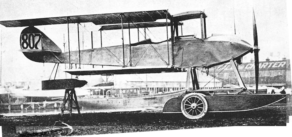
Designed for reconnaissance duties, the two-seat Sopwith Admiralty Type 807 seaplane emerged in 1914. Powered by a 100hp Gnome Monosoupape, the machine had a top level speed of 80mph at sea level. Serial no 807, seen here, was the first of these aircraft delivered to the RNAS, their serial nos being 807-810 and 919-926. Both 920 and 921 arrived in East Africa on 21 February 1915, where despite being adversely affected by the climate, they played a part in the ultimate destruction of the German cruiser, Konigsberg, on 11 July 1915.
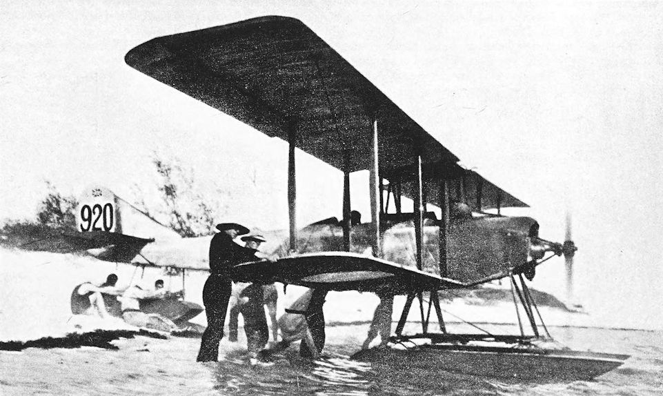
Sopwith 807 photographed at Niororo Island. The engine cowling has been removed to improve the cooling of the engine, and this aircraft has an enlarged fin.
In this view of Folder No.920 the uncowled engine (increasing cooling airflow and decreasing weight) is even more in evidence than the vertical tail surfaces, which differ from those seen in the side view of No.807.
In this view of Folder No.920 the uncowled engine (increasing cooling airflow and decreasing weight) is even more in evidence than the vertical tail surfaces, which differ from those seen in the side view of No.807.
Sopwith Gordon Bennett Racer
FOR the 1914 Gordon Bennett race the Sopwith company produced a remarkably clean single-seat biplane. It was powered by an 80 h.p. Gnome engine which was cleanly cowled in what, twenty years later, would have been called a long-chord cowling. The fuselage had faired sides, and a neat vee undercarriage was fitted.
It was obvious that great care had been taken to reduce drag as much as possible; but in doing so the fin and rudder were reduced to dangerously small proportions. The maximum speed proved to be 105 m.p.h., an excellent performance on only 80 h.p.
Two machines of this type were built, and were impressed by the Admiralty on the outbreak of war, doubtless with the intention of using them as high-speed single-seat scouts. The Gordon Bennetts were given the serial numbers 1214 and 1215. Their service history is unfortunately obscure.

Sopwith Gordon Bennett Racer.
Sopwith Greek Seaplane and Gun Buses
<...>
In March, 1914, the Greek Government ordered six more Sopwith pushers of similar type, but required them to be armed with a machine-gun mounted on the nose of the nacelle; there was to be no dual control. Construction of these machines was under way when war broke out.
The Greek gun-carriers were at once commandeered by the Admiralty, and the mere fact that they were capable of carrying a machine-gun was an instant commendation. The machines appeared with wheel undercarriages: at first a simple skid structure was fitted directly under the first pair of interplane struts on either side and carried a pair of wheels on a short axle. The first Sopwith Gun Buses, as they were called, had the 100 h.p. Gnome Monosoupape engine, and the nose of the nacelle was modified in shape to improve the gunner’s field of fire forwards and downwards.
A more powerful version of the design appeared later, and differed in appearance from the Gnome-powered Gun Buses. The use of the 150 h.p. Sunbeam engine dictated the provision of a stronger nacelle and undercarriage. The nacelle was larger than that of the Gnome-powered version, and had deep coamings about the cockpits; it was raised slightly above the lower wing. A larger, balanced rudder and a new tailplane and elevators were fitted. The undercarriage was attached to the nacelle and lower centre-section; it had only two wheels, connected by a transverse axle which was bound to the long horizontal skids by rubber cord.
Whether any of the Gun Buses flew operationally is uncertain, but Commander C. R. Samson reported to the Admiralty on February 6th, 1915, that the equipment of his squadron, then based at Dunkerque, included “One Sopwith Gun aeroplane, [which] requires a lot of work on it to make it safe to fly.”
SPECIFICATION
Manufacturers: The Sopwith Aviation Co., Ltd., Canbury Park Road, Kingston-on-Thames.
Other Contractors: Robey & Co., Ltd., Lincoln.
Power: Gun Bus: 100 h.p. Gnome Monosoupape; 150 h.p. Sunbeam.
Dimensions (with Sunbeam engine): Span: 50 ft. Length: 32 ft 6 in. Chord: 5 ft 1 1/2 in. Gap: 5 ft 6 in. Stagger: 1 ft. Dihedral: 3 30'. Incidence: 4.
Areas: Wings: upper 246 sq ft, lower 228 sq ft, total 474 sq ft. Ailerons: each 15 sq ft, total 60 sq ft. Tailplane: 28 sq ft. Elevators: 28 sq ft. Fin: 8-75 sq ft. Rudder: 13 sq ft.
Performance: Maximum speed: 80 m.p.h. with Sunbeam engine.
Armament: One Lewis machine-gun on movable mounting on nose of nacelle.
Service Use: Probably used by Commander Samson’s squadron of the R.N.A.S. stationed at Dunkerque. Training: flown at Hendon.
Serial Numbers: 801-806: built by Sopwith. 3833-3862: built by Robey & Co.; only seventeen were delivered complete, the remainder being delivered as spares.
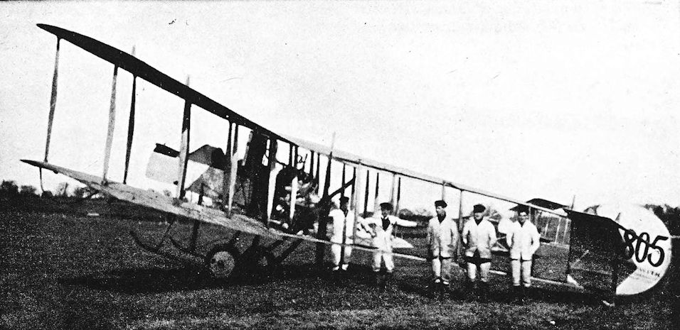
Sopwith Gun Bus photographed at Hendon.
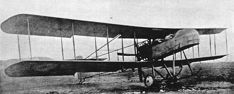
Sopwith Gun Bus with 150 h.p. Sunbeam engine.
Sopwith Greek Seaplane and Gun Buses
IN 1913 the Sopwith company produced a two-seat pusher biplane seaplane, powered by a 100 h.p. Anzani radial engine and fitted with dual control. It was a typical nacelle-and-tail-booms pusher with four-bay wings of equal span; an unusual characteristic of the design was the forward rake of the upright struts between the tail-booms. There were two single-step main floats and a small tail-float. The tail-unit bore a family resemblance to that of the Bat Boat No. 2.
This machine was bought by the Greek Government. It was flown at Eleusis, whence Collyns P. Pizey had gone in September, 1913, to organize the Greek Naval Air Service, and did some useful work. The Sopwith pusher seaplane was still flying in 1915, thanks to the attention given to it by the four British mechanics whom Pizey had taken with him. This performance was the more meritorious because there were at first no hangars or workshops at Eleusis, and the seaplane had to be moored in the open.
<...>
SPECIFICATION
Manufacturers: The Sopwith Aviation Co., Ltd., Canbury Park Road, Kingston-on-Thames.
Power: Greek Seaplane: 100 h.p. Anzani.

Sopwith Greek Seaplane.
Sopwith Schneider and Baby Seaplanes
THERE was no British entry in the first Schneider Trophy contest for seaplanes, which was held in 1913. For the 1914 contest the Sopwith company built a floatplane version of the Tabloid and fitted it with the 100 h.p. Gnome Monosoupape engine in place of the standard 80 h.p. Gnome. The vertical tail assembly differed from that of the original Tabloid: it consisted of a triangular fin and a plain rudder.
The seaplane was originally fitted with a single wide central float but, when launched at Hamble early in 1914, it turned over on to its back immediately the engine was opened out. The pilot, Howard Pixton, was thrown into the Hamble River and the Tabloid seaplane suffered immersion for several hours.
The damaged aircraft was returned to the Sopwith works, where it was rebuilt. Of necessity the rebuilding was done in a remarkably short time; so short, in fact, that to re-design the float undercarriage completely was out of the question. A somewhat crude but effective expedient was adopted: the large single float was simply cut in halves longitudinally and the resultant openings were filled in, thus providing two separate floats. Thus modified, the Tabloid seaplane made its first flight from the Thames at Glovers Island on April 8th, 1914. Pixton was well satisfied with the machine’s flying qualities, and it was despatched to Monaco for the Schneider Trophy contest.
It flew again on the eve of the race, April 19th; a new airscrew was fitted and some minor modifications were made.
The rest is now history. The Tabloid seaplane eclipsed all other contestants, and Pixton won easily at an average speed of 86-75 m.p.h. The Tabloid reverted to a landplane soon after its return to England, but retained its 100 h.p. engine.
The seaplane was more or less forgotten until the demands of war indicated a need for fast single-seat seaplanes. The Tabloid seaplane was put into production in November, 1914, and was supplied to the R.N.A.S. In the Service, the little seaplane was appropriately known as the Sopwith Schneider.
The production Schneiders resembled Pixton’s machine closely. The 100 h.p. Gnome Monosoupape was fitted in a fore-and-aft mounting, with a bull-nose cowling over its upper half. Lateral control was by wing-warping. The tail unit resembled that of the Tabloid seaplane, but the Schneider’s fin and rudder were of slightly greater area. An additional diagonal strut was introduced in each side of the undercarriage, and a small aperture was made in the centre-section to permit the installation of a Lewis gun.
Later production machines had ailerons instead of wing-warping, and an enlarged fin was fitted: this had a humped leading edge and remained a characteristic feature of the Schneider.
One Schneider was experimentally fitted with Linton-Hope type floats. These floats were built on the same principle as the flying boat hulls designed by Major Linton-Hope, and were of good streamline form. With them the Schneider’s maximum speed was increased by 8 m.p.h., but they were not standardised.
Production Schneiders became available early in 1915, and were immediately issued to seaplane stations around the English coast and to various ships. They were used for patrol duties against enemy submarines and airships: in the former case a single 60-lb bomb was carried, and in the latter incendiary ammunition was provided for the Schneider’s single Lewis gun.
As a high-performance single-seat seaplane, the Schneider seemed to be the weapon most likely to combat the Zeppelins which, early in 1915, began to hamper the activities of the normal British naval patrols in the North Sea. The earliest recorded attempt made by a Schneider to get to grips with a Zeppelin came to naught. On May 11 th, 1915, while the seaplane carrier Ben-my-Chree was participating in an attempt to attack Norddeich, a Zeppelin was sighted as the British force approached the German coast. The Ben-my-Chree had a trackway forward of the superstructure, and a Schneider seaplane was forthwith mounted on wheels with the intention of flying it off the trackway to attack the airship. But the Schneider’s engine backfired and wrecked the rather makeshift launching gear, and the attempt had to be abandoned.
Schneiders went to sea with light cruisers of the North Sea Patrol in order to attack Zeppelins whenever possible. The Arethusa got her Schneider away on June and, 1915, when a Zeppelin was sighted, but the pilot returned to the cruiser without pressing home an attack because he had mistakenly thought he was being recalled.
More ignominious was the debacle of July 4th, 1915, when, with four Zeppelins overhead, three brand-new Schneiders belonging to the carrier Engadine were hoisted out. The floats of all three broke up on the water, and only one could be salved: the enemy escaped scot free.
Occurrences of this kind did little to encourage sceptical naval officers to rely upon seaplanes in general; yet the value of aircraft for spotting for ships’ guns was indisputable. The trouble lay in the need to hoist out seaplanes from their carrier vessels for take-off; and the frail wooden floats of the period could not withstand a rough sea. Late in July, 1915, Admiral Sir John Jellicoe suggested that the solution lay in flying a seaplane from the deck of the carrier Campania.
That ship has been discussed in the description of the Fairey Campania seaplane, and it will be recalled that in July, 1915, she was fitted with a forward flying-off deck 120 feet in length. The idea of putting a Schneider on wheels had already been tried on the Ben-my-Chree, and this was done on Campania also: the seaplane’s main floats rested on a two-wheeled dolly, which dropped into the sea after the take-off run was completed. The first take-off was made by Flight Lieutenant W. L. Welsh on August 6th, 1915, with Campania steaming into wind at 17 knots; the take-off run of the Schneider was 113 feet.
The year 1915 saw the Zeppelin campaign of air-raids on England gain momentum. As a means of intercepting the airships in daylight before they reached the English coast it was proposed to equip shallow-draught paddle steamers with four seaplanes each, and with them to carry out patrols 50 miles east of the coast. In point of fact, only two such paddle steamers were provided at the end of March, 1916: they were the Killingholme and Brocklesby, based at Killingholme and Yarmouth respectively, and each carried two or three Sopwith Schneiders.
The Harwich Command conducted several interesting experiments with aircraft and submarines. In April and May, 1916, the submarine E.22 took Sopwith Schneiders to sea on her deck; the seaplanes were successfully launched and flown back to Felixstowe. It was, of course, impossible for the submarine to submerge while carrying the Schneiders, but it is interesting to recall that the Germans carried out exactly similar experiments with a Friedrichshafen two-seat seaplane.
The Schneider served at the Dardanelles, in the Aegean and in the Eastern Mediterranean. On April 8th, 1915, the aircraft carrier Ark Royal went to Mudros, where she exchanged the two Tabloids she had brought out from England for two Schneiders. At the end of April, 1915, one of these Schneiders was lent to the light cruiser Doris as a replacement for a Sopwith Seaplane Type 807: this Schneider made several important reconnaissance flights over Smyrna.
In November, 1916, the Schneider was still in use in the Aegean. On the 21st of that month Flight Sub-Lieutenant A. F. Brandon, flying a Schneider, shot down an enemy aeroplane which had attacked the airship shed at Mudros.
In the eastern Mediterranean and in the Red Sea the Schneider was used by the carrier vessels Ben-my-Chree, Empress, Anne and Raven II. These ships carried out many operations designed to harass the Turks, and the Schneiders were called upon to bomb, spot for guns, make reconnaissances, and escort the Short two-seat seaplanes also carried by the ships.
As the year 1915 progressed, more and more was expected of the Schneiders as they unobtrusively went about their unspectacular duties. The machines gradually accumulated additional items of equipment, and their performance began to deteriorate. More power was provided by installing the 110 h.p. Clerget engine in place of the Monosoupape, and with the new engine the nose of the machine underwent a change. The Clerget had an overhung mounting, and an open-fronted cowling of horse-shoe shape was fitted.
This development, which first appeared in September, 1915, was known as the Sopwith Baby, but the old name Schneider continued to be applied loosely to Schneiders and Babies alike; whilst, conversely, the new name came to be used equally loosely to describe the earlier machine. Thus there is much confusion in most of the records of the exploits of both types.
The armament of the Baby usually consisted of a single Lewis gun mounted on top of the fuselage and synchronised to fire forward through the airscrew. This was an improvement upon the Schneider’s armament, for the earlier aircraft had had its Lewis gun attached to the centre-section, firing upwards to clear the airscrew. Nevertheless, some Babies retained the earlier armament installation, and the synchronised Lewis gun was not altogether standard.
Like the Schneider before it, the Baby was used as part of the equipment of early aircraft carriers. Two Babies and three Short 184s of the Vindex were hoisted out not far from Horn Reefs on March 25th, 1916; their objective was a supposed Zeppelin base at Hoyer. Snow made the flight a hazardous one, and two of the Shorts and one of the Sopwiths were lost.
The next attempt to use Sopwith Baby seaplanes to bomb the Zeppelin base, now known to be at Tondern, was made on May 4th, 1916. It was an utter fiasco. Soon after 3 a.m. eleven Sopwith Babies were hoisted out from the carriers Vindex and Engadine off the island of Sylt. Four broke their airscrews, three had engine failure, and one overturned in the wake of one of the escorting destroyers. Of the three machines that succeeded in getting away one struck the wireless aerial of the destroyer Goshawk and crashed; the second was forced to return with engine trouble; and only the third reached Tondern. The target was partly obscured in mist, and the two 65-lb bombs which alone out of the intended twenty-two were transported to their destination missed the target.
Deck take-offs with wheeled dollies were practised on the Campania, on May 29th, 1916, five Sopwith Baby seaplanes flew off the carrier’s deck while she W'as steaming at 19 to 20 knots. When the Campania belatedly put to sea on 31st May, following the Grand Fleet to the engagement which history was to know as the Battle of Jutland, she had on board three Sopwith Babies, four Schneiders, and three Short 184s. Two more Baby seaplanes were on the Engadine, but were not used during the battle.
On June 24th, 1916, four Sopwith Baby seaplanes were transferred to Dunkerque from the Vindex. This was done to provide fighter aircraft for use with patrol ships, and to augment the landplane fighters then in use at Dunkerque. These Babies were also used for patrol duties and as escorts to the two-seaters; and in May, 1917, a further nine Baby seaplanes were allotted to Dunkerque. Two months later, however, the seaplanes were replaced by Sopwith Pups.
The Baby served in the Mediterranean area, both from seaplane stations and from the carrier Ben- my-Chree. Three of the ship’s Babies bombed the Chikaldir railway bridge over the river Jeihan on December 27th, 1916. Short seaplanes from the Ben-my-Chree and Raven II also took part in this raid, which delayed the passage of heavy guns to Baghdad.
Six Baby seaplanes were specified as part of the establishment of the seaplane station at Otranto in February, 1917; and in the Aegean three Babies operated as fighters from Thasos. The seaplane carrier Empress had four Sopwith Baby and two Hamble Baby seaplanes in November, 1917. These machines played a part in the Palestine campaign: on November 2nd three of them bombed the railway bridge at Jaljulye, and later in the day seaplanes from the Empress bombed an oil factory near Haifa.
The usual bomb-load for the Baby consisted of two 65-lb bombs. In addition to these missiles it carried a Lewis gun and ammunition, pigeon, emergency rations and a sea anchor; consequently it became overloaded and somewhat dangerous to fly. Modified versions of the type were built by the Fairey and Blackburn companies. The former manufacturer made an excellent contribution towards the improvement of the aircraft’s weight-lifting capabilities by fitting the Fairey Patent Camber Gear: this version of the type was known as the Fairey Hamble Baby.
The Blackburn company built seventy-one Sopwith Baby seaplanes with the 110 h.p. Clerget engine. Ten of the first production batch of Blackburn-built Babies had an experimental modification to the wings. To make a worthwhile improvement in performance it was considered that more power was necessary, and it was decided to fit the 130 h.p. Clerget in the Baby airframe.
When this decision was reached, the Sopwith company was fully occupied with the production of Camels, and was unable to divert any of its resources to the necessary re-design and modification work. The task was left to the other contractors, and Blackburn and Fairey made their own modifications for the use of the more powerful engine.
The Fairey Hamble Baby did not change its name when powered by the 130 h.p. engine, but the Blackburn-built version was sometimes known as the Blackburn Baby. Externally there was nothing to distinguish the 130 h.p. Blackburn-built Baby from the standard 110 h.p. version. The first batch of forty were all originally armed with containers of Ranken darts; they carried no machine-guns. Later, however, some at least were armed with a single synchronised Lewis gun.
The 130 h.p. Babies were distributed quite as widely as their lower-powered predecessors. Two Blackburn-built machines from Imbros made a bombing attack on the German cruiser Goeben on January 20th, 1918, but failed to hit it. The Babies and their escorting Camels were attacked by ten enemy seaplanes, and one Baby was shot down in flames. The other, flown by Flight Sub-Lieutenant R. W. Peel, returned to Imbros in a series of hops. Peel’s engine was faulty; he had to taxi part of the way and fly when his engine permitted him to do so.
A third development of the Baby design was the Port Victoria P.V.1, in which special high-lift wings replaced the standard mainplanes.
Seaplanes of the Sopwith Baby type remained in service until the end of the war. Doubtless the majority of the fifty-eight which were on charge at the end of October, 1918, were the Blackburn version with 130 h.p. Clerget, but that does not alter the fact that the basic design was by then five years old, for the Baby could trace its ancestry back to the Sopwith Tabloid of 1913. It was an aeroplane which was at its best when doing unspectacular patrol work. It is perhaps best summed up in these words of a former pilot of the Great Yarmouth Air Station (who, it will be observed, uses the original name of Schneider, even though writing of the 1918 period):
“It was the machine for the lover of solitude and independence and a wandering kind of life.
“The Schneider was a sort of detective, exposing all mysteries, such as whales mistaken for submarines, streaks of oil, and rescuing colleagues in difficulties. Any wild rumour - out went the Schneider to investigate! They were the Police Force of the Yarmouth Patrol.”
In 1918 a number of Blackburn-built Babies were supplied to the Royal Norwegian Naval Air Service. These machines had interchangeable ski, wheel or float undercarriages.
SPECIFICATION
Manufacturers: The Sopwith Aviation Company, Ltd., Canbury Park Road, Kingston-on-Thames.
Other Contractors: The Blackburn Aeroplane & Motor Co., Ltd., Olympia, Leeds.
Power: 100 h.p. Gnome Monosoupape; 110 h.p. Clerget; 130 h.p. Clerget.
Dimensions: Span: 25 ft 8 in. Length: 22 ft 10 in. (23 ft with 130 h.p. Clerget). Height: 10 ft. Chord: 5 ft 2 in. Gap: 4 ft 6 in. Stagger: 8 in. Dihedral: 2°. Incidence: 3°. Span of tail: 9 ft 5 in.
Areas: Wings: upper 128 sq ft, lower 112 sq ft, total 240 sq ft. Ailerons: each 7 sq ft, total 28 sq ft. Tailplane: 14 sq ft. Elevators: 12 sq ft. Fin: 2-7 sq ft. Rudder: 6-5 sq ft.
Weights: 110 h.p. Clerget. Loaded: 1,580 lb. 130 h.p. Clerget. Empty: 1,226 lb. Military load: 75 lb. Pilot: 180 lb. Fuel and oil: 234 lb. Loaded: 1,715 lb.
Performance: 110 h.p. Clerget. Maximum speed at sea level: 92 m.p.h. 130 h.p. Clerget. Maximum speed at sea level: 100 m.p.h. Climb to 10,000 ft: 35 min. Endurance: 2 1/4 hours.
Tankage: Petrol: 25 gallons. Oil: 6 gallons.
Armament: Originally a Lewis machine-gun was mounted in an aperture in the centre-section and fired at a shallow upward angle to clear the airscrew. Later Sopwith Babies had a synchronised Lewis gun mounted centrally on top of the fuselage, firing forward through the airscrew. Occasionally, as on Baby No. 8151, the gun was mounted above the upper starboard longeron. No. 8160 had a Lewis gun fixed to the port centresection struts to fire upwards at about 450 to the line of flight; the gun itself had been turned through 90° from its normal attitude and was mounted so that the drum of the Lewis gun was in the vertical plane. The Schneider could take one 65-lb bomb; the Baby’s load consisted of two such bombs carried in racks under the fuselage. At least one Baby was fitted with Le Prieur rockets, which were carried in racks attached to the interplane struts. Ranken darts were also used for anti-airship work.
Service Use: R.N.A.S. Seaplane Stations at Calshot, Dundee, Dunkerque, Great Yarmouth, Felixstowe, Scapa Flow, Westgate, Killingholme and Fishguard. Aircraft carriers Ark Royal, Ben-my-Chree, Engadine, Furious, City of Oxford, Peony, Riviera, Campania, Vindex, Anne, Raven II, Empress, Manxman. Paddle steamers Brocklesby and Killingholme. Gunboat Halcyon. Carried by certain light cruisers, e.g., Arethusa, Undaunted, Doris. Submarines: Schneiders used experimentally with submarine E.22. Mediterranean: R.N.A.S. Seaplane Stations at Otranto and Santa Maria di Leuca. Aegean: R.N.A.S. Stations at Thasos, Suda Bay and Syra. Egypt: R.N.A.S. Stations at Port Said and Alexandria. Also used by the Royal Norwegian Naval Air Service.
Production and Allocation: Serial numbers indicate that 136 Schneiders and 286 Baby seaplanes were built. On October 31st, 1918, fifty-eight Babies were on charge with the R.A.F.: twenty-one were in the Mediterranean, three were with the Grand Fleet, and the remainder were at various coastal stations in the United Kingdom.
Serial Numbers: Schneider: 1436-1447, 1556-1579 (built under Contract No. C.P.38624/15), 3707-3806. Baby: 8118-8217, built by Sopwith (8118-8122 had the Monosoupape engine, remainder the 110 h.p. Clerget). N.300, N.1010-N.1039, N.1060-N.1069 and N.1100-N.1129 were all built by Blackburn. N.1410-N.1449 were built by Blackburn with 130 h.p. Clerget, armed with Ranken darts. N.2060-N.2134 were built by Blackburn with the 130 h.p. Clerget.
Notes on Individual Machines: 1557: attached H.M.S. Undaunted. 1558: R.N.A.S., Great Yarmouth. 1560 and 1561: H.M.S. Ben-my-Chree. presented to Canada. 3736: R.N.A.S., Great Yarmouth. 3806: presented to Canada. 8125: crated and despatched to Canada without engine. 8134: became Hamble Baby prototype. 8151: R.N.A.S., Felixstowe. 8164: R.N.A.S., Great Yarmouth. 8214: sold to Italy. N.1030-N. 1039 had experimental wing modification. N.1033: R.N.A.S. Seaplane Station, Fishguard. N.1063: R.N.A.S. Seaplane Station, Dundee.
Costs:
Sopwith Baby airframe without engine, instruments and gun £1,072 10s.
130 h.p. Clerget engine £907 10s.

Production Schneider with enlarged fin and ailerons in place of wing-warping.
One of the last Schneiders. No. 3804, showing all the main identifying features of the type - especially the engine cowling
One of the last Schneiders. No. 3804, showing all the main identifying features of the type - especially the engine cowling

Schneider with experimental Linton Hope floats.

А typical Blackburn-built Baby, with characteristically cowled Clerget engine and upward-firing Lewis gun.

A Blackburn-built Sopwith Baby in American markings and with a U.S. Navy serial number. A few Schneiders and Babies were supplied to America during the war.

Sopwith Baby No. 8160 with upwards-firing Lewis gun.

Sopwith Baby with experimental installation of a synchronised Lewis gun on upper starboard longeron. The aircraft in the left background is a Wight 840 seaplane.

Sopwith Baby No. 8165 with centrally-mounted synchronised Lewis gun.
Sopwith Seaplane, Admiralty Type 860
THIS little-known Sopwith seaplane was contemporary with the Short 184 and Wight 840; like them it was powered by the 225 h.p. Sunbeam engine and was designed to carry a torpedo. In common with its contemporaries it was given a designation derived from the serial number of an aircraft of the first production batch, and was known as the Sopwith Seaplane Type 860. It was not the first torpedo-carrying seaplane of Sopwith design, for it was preceded by the Type C seaplane of 1913, which had flown successfully with a 14-inch torpedo late in that year.
The Sopwith 860 was a two-seater which, in its standard form, had three-bay wings of equal span arranged to fold on the Short principle. The engine had a frontal radiator, and a massive central exhaust stack was fitted. The sprung floats were single-step pontoon structures, and torpedo crutches were fitted at the centre of each of the two cross-bars. There was a single tail-float, and stabilising floats on unusually long struts were mounted under each lower wing-tip. The fin and rudder were an ill-assorted combination: it appeared that a rudder similar to those of earlier Sopwith seaplanes was used, together with a new fin which, in order to provide the necessary area, had a humped leading edge.
An unequal-span version of the type also existed, as the second illustration shows. The extensions of the upper wing were braced from king-post structures; and longer ailerons were fitted to the upper main-plane only.
The aircraft was flown from the rear cockpit. There was an aperture in the centre-section directly above the observer’s cockpit, and it seems probable that he would be provided with a gun-mounting above the upper mainplane.
The Sopwith 860 was built in small numbers, but no large-scale production was undertaken; four of the machines of the second batch were not delivered. No doubt the lack of further orders for Sopwith 860s was attributable to the decision to standardise the Short 184, but the Sopwith type remained in service until 1916 at least.
SPECIFICATION
Manufacturers: The Sopwith Aviation Co., Ltd., Canbury Park Road, Kingston-on-Thames.
Power: 225 h.p. Sunbeam.
Armament: One 14-inch torpedo, weighing 810 lb. It is probable that a single Lewis machine-gun could be fitted to a mounting above the upper centre-section.
Service Use: Flown at R.N.A.S. Station, Isle of Grain.
Production: Serial numbers were allocated for at least twenty-two Sopwith 860s, but four were not delivered.
Serial Numbers: 851-860; 927-938, of which 933, 934, 936 and 937 were not delivered.
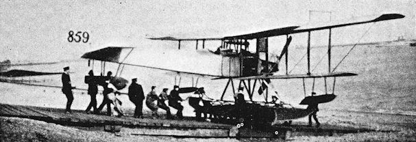
Unequal-span version of the Sopwith 860 at Isle of Grain, 1916.
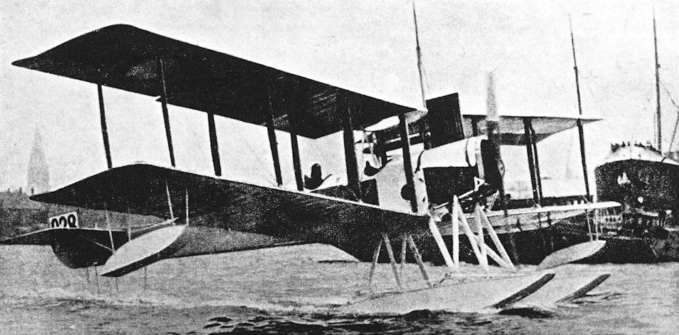
Sopwith Seaplane, Admiralty Type 860.
Sopwith 1 1/2-Strutter
THE first Sopwith aeroplane to make a resounding name for itself was the quaintly-named 1 1/2-Strutter. More than one reason has been given for the machine’s odd name, but the most credible seems to be that which attributes it to the outer struts of the central wing-bracing: these were said to look like half-size interplane struts which, by virtue of their shortness, had to be attached to the upper longerons instead of to the lower wing. Originally, of course, the name was unofficial. To the Admiralty the machine was known as the Sopwith Type 9700, and the R.F.C.’s first official designation for it was Sopwith Two-Seater.
The 1 1/2-Strutter was first built for the Admiralty. The prototype was completed late in 1915, and was passed by the Sopwith experimental department on December 12th, 1915. It was a handsome two-seat biplane, powered by a 110 h.p. Clerget rotary engine which was installed on an overhung mounting and had a circular open-fronted cowling. The single-bay wings were of equal span, and were characterised by the W-shaped arrangement of cabane struts which had first appeared on the so-called Sigrist Bus.
The 1 1/2-Strutter was the first Sopwith aeroplane to have the shape of fin and rudder which was to appear, in easily recognisable variations, on many later Sopwith types. It was also fitted with the characteristic Sopwith undercarriage, in which each wheel was mounted on a half-axle with its inner end pivoted at the mid-point of the spreader-bars; shock absorption was by means of the rubber cord which bound each half-axle to the apex of the corresponding vee-strut.
The structure of the 1 1/2-Strutter was quite conventional: wire-braced wooden members were covered with fabric, with plywood decking about the cockpits. The pilot sat directly under the upper wing, and the observer’s cockpit was some way aft; the space between the cockpits was occupied by the main fuel tanks.
Two features which were unusual in 1915 were the adjustable tailplane, the incidence of which could be varied in flight by means of a control-wheel in the cockpit, and the air-brakes. The latter consisted of two square surfaces in the trailing portion of the lower centre-section; when fully applied these surfaces tilted upwards until they were at right angles to the airstream. Their hinges were set back a short distance from their forward edges: thus a balancing effect was obtained from the small portion which projected below the wing. These air-brakes in no way resembled latter-day trailing-edge flaps.
The Admiralty ordered 150 Sopwith 1 1/2-Strutters for the R.N.A.S., and deliveries began in the early spring of 1916. By the end of April that year, No. 5 Wing of the R.N.A.S. at Coudekerque had one Flight of the new type. The Wing had arrived at Coudekerque only in the preceding month, and was intended to serve as a bombing unit. The 1 1/2-Strutters were used both as escorts to the Caudron G.IVs and Farman 40s, and as bombers in their own right.
On August 9th, 1916, Flight Sub-Lieutenants R. H. Collet and D. E. Harkness flew their 1 1/2-Strutters without observers to bomb the airship sheds at Evere. Each pilot dropped eight le Pecq bombs on the large hangar, and Harkness dropped four more on the hangar at Berchem Ste. Agathe. On the 18th, four 1 1/2-Strutters bombed an ammunition dump at Lichtervelde and left part of it burning; on the 25th, two Sopwiths bombed the Zeppelin hangars at Cognelee; and on September 2nd, three of No. 5 Wing’s 1 1/2-Strutters attacked the shipyards at Hoboken.
That the R.N.A.S. bombing programme did not develop further at that time was attributable to a remarkably unselfish act of the Admiralty. It had been hoped that the new No. 3 Wing, based at Luxeuil for strategic bombing, would have been fully equipped with twenty 1 1/2-Strutters and fifteen Short Bombers by July 1st, 1916. But in those critical weeks which preceded the opening of the Battle of the Somme the Royal Flying Corps found itself short, by twelve squadrons, of the number of aeroplanes needed for the operation. General Henderson thought that the smallest possible reinforcement must consist of four fighting squadrons or seventy-two aeroplanes, but a thorough search of all R.F.C. units at home produced twelve aircraft.
The War Office thereupon appealed to the Admiralty for assistance, and it is to the latter Department’s eternal credit that it recognised the seriousness of the situation and made an immediate and effective response by handing over considerable numbers of 1 1/2-Strutters. By the middle of September, 1916, sixty-two machines had been handed over, and in all seventy-seven were transferred to the R.F.C. The details of the transferred 1 1/2-Strutters are appended. This action by the Admiralty considerably delayed the equipping of No. 3 (Naval) Wing.
The 1 1/2-Strutter had also been ordered for the R.F.C., and the first contract, for fifty machines, was placed with Ruston, Proctor & Co. about the end of February, 1916. The first of these 1 1/2-Strutters were supplied to No. 70 Squadron, and so urgent was the need for fighting aircraft in France that the squadron went overseas by Flights as machines became available. The first Flight (“A” Flight) went to France on May 24th, 1916, and “B” Flight arrived on June 29th. The third Flight, which arrived on July 30th, was equipped with 1 1/2-Strutters which had been transferred from the R.N.A.S.
This is perhaps the most appropriate point at which to mention the 1 1/2-Strutter’s armament. As a fighting aircraft it is of great historical importance, for it was the first British aeroplane to go into service equipped with a synchronising gear which made it possible to fire a machine-gun through the revolving airscrew. British experiments with synchronising and interrupter gears had been under way for some considerable time before the first example of the Fokker interrupter gear fell into British hands on April 8th, 1916, and the enemy device neither prompted nor inspired British development of such gears.
On the 1 1/2-Strutter a single Vickers gun was mounted on top of the engine cowling and fired forward. The machines built for the R.F.C. had the Vickers synchronising gear installed, and it was this type that was used by the first two Flights of No. 70 Squadron. The R.N.A.S. favoured the Scarff-Dibovski synchronising gear, however, and it was standardised on R.N.A.S. 1 1/2-Strutters. The basic idea had been put forward by Lieutenant-Commander V. V. Dibovski of the Imperial Russian Navy in January, 1916, and the mechanism proper was designed by Warrant Officer F. W. Scarff of the Air Department of the Admiralty. The ex-R.N.A.S. 1 1/2-Strutters used by “C” Flight of No. 70 Squadron had the Scarff-Dibovski synchronising gear. Later machines also had the Ross and Sopwith-Kauper gears which, like the Vickers and Scarff-Dibovski gears, were purely mechanical.
The mounting for the observer’s Lewis gun underwent several changes. The earliest production 1 1/2- Strutters had the Scarff socket and pillar mounting, which was a rather rudimentary affair and allowed only a limited movement of the gun. This was soon superseded by the Nieuport ring-mounting which allowed the gun to be swung in a complete circle around the rear cockpit and enabled the gun to be elevated and lowered. The Nieuport mounting was a rather cumbersome structure, however, and a much improved mounting soon followed. This further product of Warrant Officer Scarff’s inventive genius was the remarkably efficient Scarff No. 2 ring-mounting, which remained in use for over twenty years; its form and appearance are too well-known to need description here.
The first aeroplanes in the R.F.C. to have the Scarff mounting were the ex-R.N.A.S. Sopwith 1 1/2-Strutters which equipped “C” Flight of No. 70 Squadron. Its worth was instantly recognised, and General Trenchard asked that all R.F.C. 1 1/2-Strutters be fitted with the new gun-mounting. This was done as soon as supplies permitted, and the Scarff ring-mounting was standardised, not only by the R.F.C. and R.N.A.S., but by the Allies as well.
By virtue of its armament the 1 1/2-Strutter acquired further historical significance, for it was the first aeroplane to be built to what was later known as the two-seat fighter formula. That formula was to endure for nearly a quarter of a century.
In addition to transferring so many of their Sopwiths to the R.F.C., the R.N.A.S. later provided a squadron to help the R.F.C. on the Somme front. This unit was the famous No. 8 (Naval) Squadron, the equipment of which included a Flight of 1 1/2-Strutters which were supplied by No. 5 Wing. The squadron made its first patrol on November 3rd, 1916, but the 1 1/2-Strutters were soon replaced by Sopwith Pups.
The 1 1/2-Strutter was not particularly fast at combat heights, nor was it particularly manoeuvrable. In fact, Captain Norman Macmillan has recorded that it was a very stable aeroplane which strongly resisted any sudden change of attitude, and that it required all of a pilot’s strength and skill to put it into a dive. Nevertheless, the 1 1/2-Strutter gave a good account of itself throughout 1916. That it did so was probably to the credit of its double armament, for at the time of its introduction it was rare to find a tractor two-seater fitted with a forward-firing gun.
Captain W. D. S. Sanday of No. 70 Squadron scored more than one success while flying a 1 1/2-Strutter. On August 6th, 1916, his patrol met a formation of ten bomb-laden enemy machines near Bapaume. The Sopwiths fought the enemy back to their own aerodrome, and forced all the German machines to land, as they had taken off, with their bombs still in their racks. On September 6th, Captain Sanday was flying one of three 1 1/2-Strutters which were making a reconnaissance flight when they were attacked west of Busigny. In the ensuing fight, Sanday shot down one enemy machine in flames, and the Sopwiths beat off all other attacks.
But by that September, the 1 1/2-Strutter began to be outclassed, and on the 30th of the month, Sir Douglas Haig wrote:
“Within the last few days the enemy has brought into action on the Somme front a considerable number of fighting aeroplanes which are faster, handier, and capable of attaining a greater height than any at my disposal with the exception of one squadron of single-seater ‘Nieuports’, one of ‘F.E. Rolls-Royce’, and one of ‘Sopwiths’ - the last-mentioned being inferior to the enemy’s new machines in some respects though superior in others.”
On the day that Sir Douglas Haig wrote these words, No. 45 Squadron completed its equipment with 1 1/2-Strutters. The squadron arrived at Fienvillers on October 15th, 1916, and one week later lost three of its aircraft on an offensive patrol. The only other R.F.C. unit to have the 1 1/2-Strutter was No. 43 Squadron, which did not reach France until January 17th, 1917. The Sopwiths of this squadron carried out several gallant ground attack operations during the Battles of Arras and Messines.
In the autumn of 1916, production 1 1/2-Strutters began to be fitted with the 130 h.p. Clerget in place of the earlier 110 h.p. version of that engine. The new power plant made only a slight improvement in the machine’s performance, however.
Replacement of the 1 1/2-Strutter began in July, 1917, and by the end of that month, No. 70 Squadron was completely re-equipped with Sopwith Camels. No. 45 Squadron had its complement of Camels by September 1st, but it was not until October 3rd that No. 43 Squadron was completely re-equipped.
In the R.N.A.S. the 1 1/2-Strutter gave even longer service, and was very widely used. Mention has already been made of its use as a bomber by the 5th Wing of the R.N.A.S., and that service was primarily responsible for the production of a single-seat version for long-range bombing. The single-seat 1 1/2-Strutter was structurally identical to the two-seat version, but the rear cockpit and gun-ring were completely absent, and the rounded top-decking was continuous from the back of the pilot’s seat down to the tail. Bombs could be carried internally: the bomb compartment was just behind the pilot’s seat, and there were cells for twelve bombs. The Vickers gun was retained, and some of the single-seat 1 1/2-Strutters also had a Lewis gun above the upper wing. This latter gun must have been inaccessible for re-loading in flight, and may have been fitted as a reserve weapon.
The bomber version was used by the R.N.A.S. 3rd and 5th Wings, and some numbers were also delivered to the R.F.C. In several cases, production batches consisted of a mixture of single-seat and two-seat 1 1/2-Strutters; but official records do not include any references to 1 1/2-Strutter bombers operated by the R.F.C., despite the fact that no fewer than eighty-nine were delivered to that Service. The great majority went to training units, thirteen went to the Middle East, three to Home Defence squadrons, and only one to the B.E.F. in France.
The type was not used a great deal for Home Defence work. No. 44 Squadron was formed at Hainault Farm with 1 1/2-Strutters as its equipment on July 24th, 1917, but began to receive Camels during the following month.
A single-seat 1 1/2-Strutter of quite a different kind and apparently intended for Home Defence service was B.762. This machine was flown from what was normally the rear cockpit, which was provided with a faired head-rest for the pilot, and was armed with a pair of Lewis guns on a special mounting immediately in front of the windscreen. The guns pointed upwards at an angle of about 70 degrees. This 1 1/2-Strutter’s serial number falls within a batch allocated to the Southern Aeroplane Repair Depot; this may mean that it was a “home-made” conversion or rebuild, and not a true Service variant.
As time went on and production gained momentum, the R.F.C. was able to repay part of its debt to the R.N.A.S. by transferring some 1 1/2-Strutters to the latter Service. At least thirty-seven such transfers were made, and it appears that most of the transferred machines retained their original serial numbers.
The 1 1/2-Strutter was used as a ship-board aeroplane, both with a wheel undercarriage and on rigid skids. By March, 1918, H.M.S. Furious had been fitted with a landing deck abaft the funnel, and her equipment consisted of fourteen two-seat 1 1/2-Strutters and two Sopwith Pups. The landing deck was fitted with an early form of arrester gear, and at a later stage the aircraft on the Furious were fitted with skid undercarriages. On H.M.S. Vindex experiments were also carried out with a 1 1/2-Strutter, N.5601, which had a skid undercarriage: this machine was flown off a special trackway which had two long troughs in which the skids ran.
Preliminary experiments with rigid skid undercarriages on 1 1/2-Strutters had been made at the Isle of Grain. Tests were also made with a 1 1/2-Strutter which had a hydrovane at the front of its skids, and was also fitted with flotation gear: an inflatable canvas bag was fitted to each lower longeron forward of the wings. Ditching trials with these bags were successful.
Shortly after the war, a 1 1/2-Strutter was used in experiments at the Isle of Grain with a new form of landing equipment for ship-board aircraft. This device consisted of a long wire jackstay stretched between posts at a height of about 20 feet above the ground. The aircraft was fitted with a hook above the wing which had to engage with a loop of wire hanging from and free to slide along the jackstay. This procedure called for a high degree of piloting skill, and obviously could have found no application on ships, since the motion of the ship would have made the engagement of the loop an impossibility. A few successful “landings” were made with the device at Grain, but it was never developed.
Sopwith Pups had been flown successfully from short platforms mounted on top of the gun-turrets of capital ships, and it was thought possible that two-seaters might also be able to take off from such sketchy surfaces. The turret platform of the Repulse was lengthened, but the first attempted take-off, made by a 1 1/2-Strutter in March, 1918, ended in failure. Trials were continued on H.M.A.S. Australia, on which a longer platform was built, and a successful take-off was accomplished by Captain F. M. Fox on April 4th, 1918; he was flying a 1 1/2-Strutter with an observer and wireless equipment on board. His achievement was the first take-off made by a two-seat aeroplane from a British warship. After Fox had demonstrated the feasibility of flying a 1 1/2-Strutter from a turret platform it was officially decided to fit extended platforms to the forward turrets of all battle cruisers.
The 1 1/2-Strutter was used as an anti-submarine patrol aeroplane over home waters at a time when there were no seaplanes available. In April, 1917, R.N.A.S. stations, each with four 1 1/2-Strutters, were opened at Prawle Point, Mullion and Pembroke.
In the Mediterranean, anti-submarine patrols were also flown by 1 1/2-Strutters based at Otranto. These patrols began in June, 1917, and the 1 1/2-Strutters were chiefly used as stand-by aircraft because they could take off quickly when reports of a sighting of a U-boat were received. One of the Otranto-based Sopwiths scored a success on September 17th, 1917: it dropped a 65-lb delayed-action bomb just ahead of a U-boat, whereupon a large oil patch came to the surface. The U-boat was not again heard by an eight-hour hydrophone patrol.
Farther east, in the Macedonian theatre of war, the 1 1/2-Strutter was used by the R.N.A.S. units which operated from the islands in the Aegean and from Stavros on the mainland. These were “A” Squadron at Thasos, “B” Squadron at Thermi (on Mitylene), “C” Squadron at Imbros and Mudros, and “D” Squadron at Stavros. To help the R.F.C. against No. 1 Kampfgeschwader, the German mobile bombing squadron which gave so much trouble in Macedonia early in 1917, numbers of R.N.A.S. 1 1/2-Strutters were taken from “C” and “D” Squadrons to form two further units known as “E” and “F” Squadrons. In March 1917, four 1 1/2-Strutters and one Sopwith Triplane were allocated to “E” Squadron, which was sent to Hadzi Junas; there the Sopwiths were combined with B.E.12s and D.H.2s of R.F.C. Squadrons Nos. 17 and 47 to form a unit known as the Composite Fighting Squadron. The second new R.N.A.S. squadron was known as “F” Squadron, and was formed in April 1917. Its equipment consisted of both single-seat and two-seat 1 1/2-Strutters, and it operated first from Amberkoj, where it arrived on April 29th,
The 1 1/2-Strutters of “F” Squadron made many attacks on enemy dumps and camps behind the Dojran front. On May 11th, the squadron moved to Marian for bombing operations on the Struma front. Drama aerodrome, railway stations and dumps provided targets, and a major success was scored on May 25th, when an ammunition dump at Livunovo was destroyed.
Two days later, five of “F” Squadron’s 1 1/2-Strutters were destroyed in an explosion at Marian. The unit was then merged with “E” Squadron to form a new “F” Squadron which, after re-equipment at Mudros, went to Thasos on June 6th, 1917. On the 17th, “F” Squadron was withdrawn to Mudros; and at the end of July the unit went to Thermi, on the island of Mitylene, for special bombing operations in the Smyrna area. At that time the squadron had five 1 1/2-Strutter single-seat bombers, three of the two-seat fighter type, and a Sopwith Camel. Between August 1st and September 17th, the 1 1/2-Strutters flew a total distance of 13,000 miles on bombing raids which were delivered with telling effect.
The Sopwith 1 1/2-Strutter was not only used by other nations, but it was also built overseas under licence. France was interested in the type at an early date, and nine of the first 150 machines built for the R.N.A.S. were transferred to our Ally. Other transfers were made later, and included a number of the single-seat bomber version of the 1 1/2-Strutter.
Production was undertaken in France on a considerable scale, for contemporary reports indicate that 4,500 Sopwith 1 1/2-Strutters were built there. Many of them were fitted with the 110 h.p. Le Rhone engine in place of the standard Clerget. The type was used on the Western Front by a number of French escadrilles for reconnaissance and bombing duties, and some were also used by French units in Macedonia. In accordance with French practice, those 1 1/2-Strutters which were used for reconnaissance work were designated Sopwith 1A.2, and the bombers were known as the B.1 (single-seat) and 1B.2 (two-seat). When it was withdrawn from front-line service with French units the 1 1/2-Strutter was used for training purposes. Many had full dual control and were modified to have the 80 h.p. Le Rhone engine.
The 1 1/2-Strutter was also used by Belgium and Russia. Eight two-seaters from an Admiralty contract were transferred to Belgium, and Russia received one two-seater and one single-seater. Both countries received further supplies of the type, some of which may have been built in France.
At least three Belgian squadrons were equipped with 1 1/2-Strutters. When the Belgian 4th Squadron was re-equipped with the Sopwith, one of its members was First-class Sergeant-Pilot Willy Coppens, who was later to become Belgium’s leading fighting pilot. He first flew a 1 1/2-Strutter on April 29th, 1917, and two days later had his first combat on it. That combat came near to being his last, for his machine was then without a forward-firing gun, and he was attacked by four German fighters.
On July 6th, 1917, King Albert of the Belgians flew over the lines in a Sopwith 1 1/2-Strutter of the Belgian 4th Squadron, piloted by Jacques de Meeus.
Russia had 1 1/2-Strutters powered by Le Rhone and Clerget engines, and used them for reconnaissance. In the fighting in Northern Russia which followed the revolution, the White Russians operated a few 1 1/2-Strutters. Twenty 1 1/2-Strutters were supplied to the Roumanian government by Britain before the end of the war, and the type was also used by Japan and, in 1919, by Latvia.
In 1918 the American Expeditionary Force bought a total of 514 French-built Sopwith 1 1/2-Strutters. Most of these were used as trainers at Issoudun, but some were issued to the 90th Aero Squadron for frontline service. One American 1 1/2-Strutter, presumably in Navy service, was fitted with a hydrovane in front of the wheels of the undercarriage.
Numbers of 1 1/2-Strutters survived the war, and several went on the French Civil Register. At the time of writing, one example of the type is known still to exist: it is the 1 1/2-Strutter which is preserved in the Musee Royal de l’Armee et d’Histoire Militaire in Brussels.
SPECIFICATION
Weights {lb) and Performance:
Version Two-seater Two-seater Two-seater Single-seater Single-seater
Engine 110 h.p. 130 h.p. 110 h.p. 110 h.p. 130 h.p.
Clerget Clerget Le Rhone Clerget Clerget
No. of Trial Report M.79 D.21 M.125 M.129 D.23
Date of Trial Report December, 1916 November, 1916 July, 1917 August, 1917 November, 1916
Type of airscrew used on trial L.P.710C L.P.710 L.P.710C L.P.710C L.P.710C
Weight empty 1,259 1,305 1,281 1,354 1,316
Military load 160 157 160 320 344
Crew 360 360 360 180 180
Fuel and oil 370 328 404 508 502
Weight loaded 2,149 2,150 2,205 2,362 2,342
Maximum speed (m.p.h.) at
ground level 106 - - - -
4,000 ft 103 - - - -
6,000 ft 101 - - - -
6,500 ft 100-5 100 - - 102
8,000 ft 99 - - - -
10,000 ft 96-5 97-5 103 94 98-5
12,000 ft 92 - - - -
14,000 ft 86 - - - -
m. s. m. s. m. s. m. s. m. s.
Climb to
1,000 ft 1 20 - - - -
2,000 ft 2 40 - - - -
3,000 ft 4 10 - - - -
4,000 ft 5 45 - - - -
5,000 ft 7 45 - - - -
6,000 ft 9 45 - - - -
6,500 ft 10 50 9 10 10 30 14 00 12 40
7,000 ft 11 50 - - - -
8,000 ft 14 25 - - - -
9,000 ft 17 25 - - - -
10,000 ft 20 25 17 50 18 55 26 55 24 35
11,000 ft 23 50 - - - -
12,000 ft 27 40 - - - -
13,000 ft 35 00 - - - -
15,000 ft - 41 55 41 30 - -
Service ceiling (feet) - 15,500 16,000 12,500 13,000
Endurance (hours) 4 1/4 3 3/4 - - -
Manufacturers: The Sopwith Aviation Co., Ltd., Canbury Park Road, Kingston-on-Thames.
Other Contractors: The Fairey Aviation Co., Ltd., Hayes, Middlesex. Hooper & Co., Ltd., 77 Kings Road, Chelsea, London, S.W. Mann, Egerton & Co., Ltd., Prince of Wales Road, Norwich. Morgan & Co., Leighton Buzzard. Ruston, Proctor & Co., Ltd., Lincoln. Vickers, Ltd. (Aviation Department), Imperial Court, Basil Street, Knightsbridge, London, S.W. (production at Crayford works). The Wells Aviation Co., Ltd., 30 Whitehead’s Grove, Chelsea, London, S.W.3. Westland Aircraft Works, Yeovil. French Contractors: F. Liore et Olivier, Rue de Villers 46, Levallois-Perret, France. Hanriot et Cie, 84, Avenue des Moulineaux, Billancourt, Seine, France.
Power: 110 h.p. Clerget 9Z; 130 h.p. Clerget 9Bc; 135 h.p. Clerget 9Ba; 110 h.p. Le Rhone 9J; 130 h.p. Le Rhone 9Jby; 80 h.p. Le Rhone 9C.
Dimensions: Span: 33 ft 6 in. Length: 25 ft 3 in. Height: 10 ft 3 in. Chord: 5 ft 6 in. Gap: 5 ft 4 3/4 in. Stagger: 2 ft. Dihedral: 2° 23'. Incidence: 2° 10'. Span of tail: 13 ft 6 in. Airscrew diameter: 8 ft 11-9 in.
Areas: Wings: 346 sq ft. Ailerons: each 13 sq ft, total 52 sq ft. Tailplane: 35-5 sq ft. Elevators: 21-5 sq ft. Fin: 3-5 sq ft. Rudder: 7-25 sq ft.
Tankage: Petrol: 40 gallons. Oil: 9-5 gallons.
Armament: Two-seat reconnaissance version: one fixed forward-firing Vickers machine-gun mounted centrally on top of the fuselage, synchronised to fire through the airscrew by means of Vickers, Scarff-Dibovski, Ross or Sopwith-Kauper synchronising gear; one free Lewis machine-gun on pillar-mounting, Nieuport ring-mounting or Scarff ring-mounting. Twelve le Pecq bombs could be carried; and on anti-submarine patrol the bomb-load consisted of two 65-lb bombs. Single-seat bomber version: one fixed Vickers machine-gun as on two- seater; four 56-lb bombs, or equivalent weight of lighter bombs.
At least one Home Defence single-seat 1 1/2-Strutter, which was flown from what was normally the rear cockpit, had a pair of upward-firing Lewis guns immediately in front of the windscreen.
Serial Numbers:
Serial Nos. Built by For Version
3686 Sopwith R.N.A.S. Two-seat prototype.
7762-7811 Ruston, Proctor R.F.C. Two-seat fighter
9376-9425 Sopwith R.N.A.S. Two-seat fighter
9651-9750 Sopwith, under Contract No. C.P.104237/16 R.N.A.S. Mixed: 65 were two-seaters, 35 single-seat bombers
9892-9897 Sopwith R.N.A.S. Two-seat fighter
A.377-A.386 Sopwith R.F.C. Two-seat fighter
A.878-A.897 Sopwith - -
A.954-A.1053 Fairey R.F.C. Two-seat fighter
A.1054-A.1153 Vickers R.F.C. Two-seat fighter
A.1511-A.1560 Westland R.F.C. Two-seat fighter
A.1902-A.1931 Sopwith R.F.C. Two-seat fighter
A.2381-A.2430 Ruston, Proctor R.F.C. Two-seat fighter
A.2983-A.2991 Sopwith R.F.C. Two-seat fighter
A.5238-A.5337 Wells R.F.C. Two-seat fighter
A.5950-A.6149 Morgan R.F.C. Some were single-seat bombers
A.6901-A.7000 Hooper R.F.C. Two-seat fighter
A.8141-A.8340 Ruston, Proctor R.F.C. Two-seat fighter
A.8744-A.8793 Vickers R.F.C. Two-seat fighter
B.2551-B.2600 Ruston, Proctor R.F.C. Two-seat fighter
N.5080-N.5179 Sopwith R.N.A.S. N.5080-N.5087 and N.5090-N.5119 were two-seaters; remainder single-seaters
N.5200-N.5219 Mann, Egerton R.N.A.S. Single-seat bombers
N.5220-N.5249 Mann, Egerton R.N.A.S. Two-seat fighter
N.5500-N.5549 Sopwith R.N.A.S. Only N.5500-N.5537 were built; all were single-seat bombers
N.5550-N.5559 Sopwith R.N.A.S. Single-seat bombers
N.5600-N.5624 Westland R.N.A.S. N.5600-N.5604 were single-seat bombers, remainder two-seaters
N.5630-N.5654 Mann, Egerton R.N.A.S. Two-seat fighter
Service Use: Western Front: R.F.C. Squadrons Nos. 43, 45 and 70; R.N.A.S. Squadrons Nos. 5 and 8; No. 3 Wing, R.N.A.S.; French Escadrilles Nos. 13, 24, 28, 29, 54, 61, 66, in, 129, 210, 221, 222, 226; Belgian Flying Corps Squadrons Nos. 2, 3 and 4; United States Air Service 88th, 90th and 99th Aero Squadrons. Eastern Front: used by the Russians. Macedonia: R.N.A.S. “A” Squadron, Thasos; “B” Squadron, Thermi (Mitylene); “C” Squadron, Imbros and Mudros; “D” Squadron, Stavros; “E” Squadron, as part of Composite Fighting Squadron at Hadzi Junas; “F” Squadron, Amberkoj, later at Marian, Thasos, Mudros and Thermi. Also used by a French unit operating from Florina. Home Defence: R.F.C. Squadrons Nos. 37, 44. Coastal Patrol: R.N.A.S. Stations at Great Yarmouth, Mullion, Pembroke, Prawle Point. Aircraft carriers Furious, Vindex, Argus. Battleships H.M.A.S. Australia, Queen Elizabeth, Barham. Mediterranean: R.N.A.S. Station, Otranto. Training: training squadrons at Eastbourne and Shawbury; No. 31 Training Squadron, Wyton; R.N.A.S. Stations at Cranwell, Dover, Manston. Flight Observers’ School, Leysdown. American Expeditionary Force 3rd Instruction Centre, Issoudun.
Production and Allocation: Serial numbers indicate that at least 1,513 Sopwith 1 1/2-Strutters were built in Britain for the R.F.C. and R.N.A.S. Further machines may have been built for France and Russia, and reports have stated that 4,500 were built under licence in France. The R.F.C. took delivery of 607 two-seat 1 1/2-Strutters and eighty-nine of the bomber version: of these, seventy-seven were transfers from R.N.A.S. production. Also from the machines produced for the R.N.A.S., sixty-one were transferred to France, eight to Belgium and two to Russia. Of later production for the R.F.C. at least thirty-seven were transferred to the R.N.A.S. Of the R.F.C.’s 1 1/2-Strutters, 346 two-seaters and one single-seater went to the squadrons in France, thirteen single-seaters to the Middle East Brigade, fifty-six two-seaters and three single-seaters to Home Defence units, and 205 two-seaters and seventy-two single-seaters to Training Units. On October 31st, 1918, the R.A.F. had 137 two-seat 1 1/2-Strutters and thirty-four single-seaters on charge. Thirty-six two-seaters and two single-seaters were with the Grand Fleet; three two-seaters and one single-seater were with the 5th Group; three single-seaters were in Egypt; eleven two-seaters and two single-seaters were in the Mediterranean area; fifty-eight two-seaters and ten single-seaters were at various aerodromes in the United Kingdom; eleven two-seaters were at Aeroplane Repair Depots; and eighteen two-seaters and sixteen single-seaters were in store. The American Expeditionary Force bought 514 Sopwith 1 1/2-Strutters from France in February and May, 1918: 236 had the 130 h.p. Le Rhone engine, 148 had the 130 h.p. Clerget, and the remainder had the 135 h.p. Clerget. Twenty 1 1/2-Strutters were supplied to the Roumanian Government, and some went to Japan.
Notes on Individual Machines: R.N.A.S. transfers to R.F.C.: 9381, 9386-9389, 9391-9393, 9403, 9405, 9406, 9409, 9412, 9418, 9421, 9424, 9653, 9656, 9659, 9662, 9665, 9668, 9669, 9671, 9673-9691, 9693-9707, 9710, 9713, 9714, 9716, 9719, 9721, 9725, 9728, 9729, 9731, 9734, 9736-9738, 9740, 9743, 9745, 9746, 9749. R.F.C. transfers to R.N.A.S.: A.1148, A.5253, A.5260-A.5262, A.5951, A.5952, A.5982-A.6000, A.6006, A.6910-A.6913, A.6917-A.6922, A.6966, A.6985-A.6990, A.8204, A.8288, B.2551.Transfers to France: 9413, 9651, 9655, 9657, 9661, 9664, 9666, 9720, 9742, 9892-9897, N.5091, N.5092, N.5094, N.5095, N.5097, N.5098, N.5100, N.5101, N.5103, N.5104, N.5113, N.5115, N.5116, N.5118, N.5122, N.5123, N.5125, N.5146, N.5157, N.5158, N.5160, N.5502, N.5507, N.5511, N.5514, N.5523. Transfers to Belgium: N.5235-N.5242. Transfers to Russia: N.5219, N.5244. Presentation aircraft: 9378: New Zealand No. 1. 9383: Britons in Japan No. 1. 9395: Tientsin Britons No. 1. 9401: “Poverty Bay”, New Zealand No. 2. 9405: Britons in Egypt No. 1. 9423: Peking Britons No. 1. 9654: Rio de Janeiro Britons No. 1. 9667: Tientsin Britons No. 2. 9722: Sao Paulo Britons No. 1. 9739: Britons in Egypt No. 2. 9744: Britons in Italy No. I. N.5084: Sao Paulo Britons No. 2. Sopwith 1 1/2-Strutters used by No. 5 Squadron, R.N.A.S.: 9378, 9383, 9396 (bombed Zeppelin sheds at Cognelee August 25th, 1916; forced to land in Holland and interned), 9397, N.5514 (“B-3”), N.5531. Used by No. 3 Wing, R.N.A.S.: 9410, 9669, 9722, 9742, N.5089, N.5091, N.5098, N.5107, N.5115, N.5116, N.5171, N.5173, N.5174, N.5512. Used by R.N.A.S., Mudros: N.5086, N.5224, N.5517, N.5527. Used by No. 43 Squadron, R.F.C.: A.960, A.961, A.970, A.1010, A.x too (“C.5”), A.1108 (shot down by Manfred von Richthofen), A.2388, A.2401. Used by No. 45 Squadron, R.F.C.: 7774, 7775, 7792 (flown by Lt. F. T. Courtney; crashed April 4th, 1917), 7800, A.1075, A.1077, A.1083, A.1084, A.1095, A.2381, A.2382, A.2385, A.8260, B.2576, B.2583. Used by No. 70 Squadron R.F.C.: 7763, A.380, A.884, A.954, A.956, A.957, A.958, A.976, A.981, A.994, A.g95, A.996, A.997, A.1002, A.1069, A.1514, A.1902, A.1925, A.2983, A.2984, A.2986, A.8172, A.8213. Other machines: 9420: interned in Holland September 17th, 1916. 9422: R.N.A.S., Dover. A.6006: used on H.M.S. Queen Elizabeth. A.6987: skid undercarriage, modified wing-bracing. B.762: single-seat conversion for Home Defence duties; twin upward-firing Lewis guns. B.2591: flown at Eastbourne. N.5119: “F” Squadron, R.N.A.S., Stavros. N.5503: R.N.A.S., Dover. N.5601: H.M.S. Vindex. N.5630 and N.5632: R.N.A.S., Cranwell.
Costs:
Airframe without engine, instruments and guns £842 6s.
Engines:
130 h.p. Clerget £907 10s.
110 h.p. Le Rhone £771 10s.

Standard production 1 1/2-Strutter with Scarff ring-mounting on rear cockpit. This machine was built by Mann, Egerton & Co.
Clear-view top-wing panels are seen here, with the gun-carrying bow of the Scarff No.2 ring-mounting depressed on another specimen of the 1 1/2 Strutter
Clear-view top-wing panels are seen here, with the gun-carrying bow of the Scarff No.2 ring-mounting depressed on another specimen of the 1 1/2 Strutter

Sopwith 1 1/2-Strutter. Early production 1 1/2-Strutter with Nieuport ring-mounting for observer’s gun. A photograph of a captured machine in German hands.

The Sopwith 1 1/2-Strutter, B.762, flown as a single-seater from the normal rear cockpit. This illustration shows the twin upwards-firing Lewis guns and clear-view cut-outs in the lower wing-roots.

Single-seat bomber version of the 1,5 Strutter, with bomb doors closed and showing clear-view top-wing panels. The Vickers gun is present and was indeed standard

Sopwith 1 1/2-Strutter in American service, fitted with a hydrovane in front of the wheels.

Sopwith 1 1/2-Strutter with skid undercarriage.
Sopwith Two-seat Biplane (The “Sigrist Bus"’)
KNOWN in the Sopwith company’s shops as the “Sigrist Bus”, after its designer, F. Sigrist, this biplane was built in 1915. It bore a certain resemblance to the Tabloid, for its 80 h.p. Gnome engine had a bull-nose form of cowling over a fore-and-aft mounting; and the provision of head fairings in front of, between and behind the cockpits recalled the similar fittings on the seaplane Type 807 and on the Spinning Jenny.
The wings of the Sigrist Bus were of unequal span, and the interplane struts had a slight outwards rake. But of the greatest interest and significance was the bracing of the upper wings at their centre point: there was no centre-section, and the two halves of the upper wing were supported by a trestle-shaped cabane structure, whilst additional support was provided by two further struts on each side which ran from the upper longerons to the main spars of the upper wing. The resulting structure resembled a letter W when seen in end elevation, and was to earn a later Sopwith biplane the curious name of “1 1/2-Strutter”.
The Sigrist Bus was a considerable time building, for Sopwith endeavours were concentrated on the Schneider seaplane scout, but the machine was flown in the early summer of 1915. Many experiments were made in attempts to vary the position of the aircraft’s centre of gravity: these included the fitting of a central skid-like projection to the undercarriage with a container holding several pounds of lead.
In June, 1915, Harry Hawker set up a new British altitude record when he flew the Sigrist Bus to a height of 18,393 feet.
The machine played no active part in the war, but is of historical interest as the precursor of the famous Sopwith 1 1/2-Strutter.
Sopwith Biplane Type SL.T.B.P.
THIS little single-seater was built in 1915. It was produced for the personal use of Harry Hawker, the Sopwith company’s great test pilot. He used it as a means of transport between the various aerodromes at which the products of sub-contractors for Sopwith types were tested.
Hawker himself had a good deal to do with the design of the aeroplane. Since production was not contemplated, no ordinary drawings were produced. Instead, full-size drawings were chalked by Hawker on the floor of the Experimental Shop in the Sopwith factory at Canbury Park Road, Kingston-on-Thames, and the machine was built on top of these chalk drawings.
Simplicity was the keynote of the design. The completed aeroplane emerged as a single-bay biplane powered by a 50 h.p. Gnome engine and characterised by clean lines and orthodox construction. The wings had pronounced stagger, and the plan-form of the tips showed a distinctive backwards rake. Wing-warping was used for lateral control.
The fuselage was a conventional wire-braced wooden structure. The undercarriage was of the Sopwith split-axle type, and the fin and rudder were also typical of Sopwith design. The tailplane echoed the shape of the wing-tips, for its extremities were similarly raked backwards.
Hawker flew the little single-seater a great deal, and used it regularly until the Sopwith Bee was built for him. It is quite remarkable that the SL.T.B.P. survived the war and was still in existence in 1926. By then it had been converted into a two-seater and was fitted with an 80 h.p. Le Rhone engine, whilst ailerons had replaced the original wing-warping system.
Although this little single-seater’s only direct contribution to the war was to expedite Hawker’s testing work by enabling him to travel quickly from one aerodrome to another, it was yet of great historical importance. It was the fore-runner of the Sopwith Pup, and its design contained many features which later appeared on that great fighter.
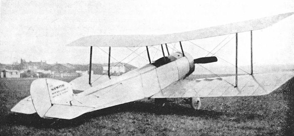
By any reckoning, at any period, the SL.T.B.P. would be considered a dainty creation - even though the pilot's upward view was deficient, as is plain from this photograph.
Sopwith Camel
ON December 22nd, 1916, the Sopwith Aviation Company’s experimental department passed out a stocky little single-seat fighter which was to have a great influence on the course of the war in the air.
The Sopwith Biplane F.1, soon to be known as the Camel, was developed from the Sopwith Pup, to which it bore a family resemblance. In flying characteristics the two aircraft were not so completely dissimilar as most accounts imply; but because the Camel was heavier, more powerful and faster, its characteristics, good and bad, were more strongly pronounced. Things happened more quickly on the Camel, and the torque effect of its bigger and heavier engine was very marked, especially when changing direction. Both aircraft were manoeuvrable, but whereas the Pup was docile, obedient, tractable, the Camel appeared waspish, wilful, intolerant.
Yet in the right hands the Camel was a lethal weapon. Its sensitivity to the controls made it the supreme dog-fighting aeroplane in the armoury of the Allies; only the Fokker Dr. I could match its manoeuvrability. The total number of enemy aircraft shot down by Camels was 1,294, a greater number than were defeated by any other single type of aeroplane of the 1914-18 war.
The Camel was a snub-nosed, hump-backed little biplane with staggered single-bay wings. The lower wing had a pronounced dihedral angle which contrasted markedly with the flat upper wing and seemed to accentuate the hump which enclosed the breeches of the two Vickers machine-guns. It was, of course, to that hump that the Camel owed its name. The name was unofficial, but so popular that it was ultimately accepted.
Structurally there was nothing unusual about the Camel. The fuselage was a wire-braced box girder with a rounded top-decking. Aluminium panels covered the first bay behind the engine; the sides were then covered with plywood as far aft as the rear of the cockpit; and the remainder of the structure was fabric-covered.
One of the factors which contributed to the Camel’s manoeuvrability was the concentration of all the greater masses within a short length of fuselage. The engine, guns, pilot and fuel were all close together in an overall length of about seven feet.
The wings were conventional wire-braced, fabric-covered wooden structures. On the prototype Camel the upper wing was in one piece, but on production machines it was made in three parts: a centre-section and two outer panels. Naturally this led to a different disposition of wing ribs in the production Camels. The spars were of spruce; the lower mainplane rear spar was solid and the others were spindled out for lightness.
The centre-section was unusually wide and extended some way outboard of the centre-section struts. These struts were splayed outwards when seen in end elevation and were made of spruce, as also were the interplane struts. Ailerons were fitted to both upper and lower mainplanes.
The prototype Camel was powered by the 110 h.p. Clerget rotary engine, but production machines had the more powerful 130 h.p. engine of the same make. The F.1 Camel was also built in some numbers with the 110 h.p. Le Rhone.
The pilot sat between the rear centre-section struts, where a considerable portion of his field of vision was obscured by the upper wing. There was the usual cut-out in the trailing edge of the centresection, and a central aperture was made between the spars in order to improve the upward view. This opening varied in width according to the tastes of individual pilots, and was longitudinally bisected by the central compression strut of the centre-section. The ailerons of production Camels were of slightly greater span than those of the prototype.
As a British fighting aeroplane the Camel’s greatest significance lay in its armament. It was the first British fighter to mount the classic weapon installation - a side-by-side pair of synchronised Vickers guns firing through the airscrew. It was not by any means the first two-gun fighter, for several earlier enemy types had had twin synchronised guns; nor was it even the first British fighter to have two guns, for it was preceded in the Service by the S.E.5 with its combination of a Lewis and a Vickers. The Camel’s firepower was, however, greater than that of the S.E.5, because the belt-fed Vickers gun had a higher rate of fire than the magazine-fed Lewis. Moreover, the Vickers gun did not suffer from the disadvantage of requiring a magazine change every 97 rounds.
The Camel was ordered in large numbers from several contractors, and deliveries began in the early summer of 1917. By the end of June, 135 Camels had been delivered to both the R.F.C. and the R.N.A.S. By the end of July, 1917, No. 70 Squadron, R.F.C., and No. 6 Squadron, R.N.A.S. were completely equipped with the type, and R.N.A.S. Squadrons Nos. 8 and 9 had begun to exchange their beloved Sopwith Triplanes for F.1 Camels. In the case of No. 9 (Naval) Squadron, re-equipment began on July 13th, 1917, and by August 4th the unit was an all-Camel squadron.
All of these squadrons, R.N.A.S. units included, had F.1 Camels with the 130 h.p. Clerget engine. So did No. 45 Squadron, the second R.F.C. unit to receive the type: its first Camel was delivered on July 25th, 1917, and the squadron was fully equipped with Camels by September 1st. No. 43 Squadron, R.F.C., was fully equipped with Clerget Camels by October 3rd, 1917. Five days later, No. 28 Squadron arrived in France equipped throughout with the type, and other Camel squadrons were soon in action.
The first Camels to see action were those used by the R.N.A.S. at Dunkerque. As early as July 4th, 1917, five Camels from that station attacked sixteen Gothas on their return journey from bombing Harwich.
On the Western Front the Camel arrived in time to participate in the Battle of Ypres which began on July 31st, 1917. The squadrons equipped with the type performed a variety of duties, chief among which was the mounting of offensive patrols; but occasionally ground-strafing attacks were made, and on October 10th, the Camels of R.F.C. Squadrons Nos. 28 and 70 carried out a bombing attack on the enemy aerodrome at Rumbeke. Only twenty-two 25-lb bombs were dropped, but much damage was done and the enemy lost at least five aircraft.
Some seven weeks earlier two pilots of No. 70 Squadron had flown their Camels at night on September 3rd in an unsuccessful attempt to attack German aircraft which bombed St. Omer. By a remarkable coincidence, three pilots of No. 44 Squadron - Major G. W. Murlis-Green, Captain C. J. Q. Brand and Lieutenant C. C. Banks - also flew their Camels that same night in the hope of intercepting the Gothas which were attacking south-east England. These flights proved that the Camel, tricky as it was, could be flown at night.
During the Battle of Cambrai more ground-attack work was carried out by the Camel units, work in which R.F.C. Squadrons Nos. 3 and 46 played a prominent part. Casualties were heavy: losses averaged 30 per cent. The enemy batteries at Flesquieres, in Lateau and Vaucelles Woods, troops and gun emplacements in Bourlon Wood and Fontaine-Notre Dame - all were the targets of the low-flying Camels and D.H.5s.
Early in February, 1918, the establishment of fighter squadrons was increased from eighteen to twenty-four aircraft. Clerget Camels were available, and it was decided to bring six Camel squadrons up to the new strength at once. Shortage of trained pilots delayed the realisation of this plan for a short time, but by March 21st, 1918, seven Camel squadrons had an establishment of twenty-four machines plus one for the squadron commander. On that day the last great German offensive of the war opened.
The Camel squadron of the V Brigade, No. 54, was required to protect the aeroplanes of the Corps squadrons; once again Nos. 3 and 46 Squadrons were detailed for ground-attack work, and their targets were carefully decided and allotted. Early fog hampered aerial activity during the morning of March 21 st, but the Camels of No. 46 attacked enemy batteries north of Bourlon Wood as early as 6 a.m.
Gallant and hazardous as those ground-attack missions were, they were unspectacular in comparison with the dog-fighting in which the Camel excelled. The aircraft owed its success to its phenomenal manoeuvrability. The elevator was extremely powerful and the ailerons sensitive, but it was the Camel’s startlingly quick reaction to coarse handling that was the undoing of so many of the pilots who attempted to fly it. At full throttle it was markedly tail-heavy, and the absence of an adjustable tailplane made it tiring to fly. It could turn in an unusually small radius, thanks to its short fuselage and the concentration of weights, but torque effect endowed its right-hand turn with characteristics different from those manifested when turning to the left. In the right-hand turn the Camel tended to drop its nose; conversely, the nose tended to rise in a left-hand turn. These tendencies had to be corrected by means of the rudder, of which a good deal was necessary, so it is hardly surprising that, if any turn were tightened too much, the Camel would quickly spin out of it.
But once a Camel pilot had become accustomed to his sensitive mount and understood its idiosyncrasies he found it to be an ideal fighting aeroplane. In combat, what the Camel lacked in speed it made up for in quickness and ease of manoeuvre. Thus one comes to read of actions such as that fought on March 22nd, 1918, when twelve Camels of No. 73 Squadron and twelve of No. 80 Squadron shot down six enemy aircraft in the course of a patrol which included three different combats, two of them against superior numbers.
Two days later, Captain J. L. Trollope of No. 43 Squadron created a record by shooting down six enemy aircraft in one day. He brought down two D.F.W. two-seaters and an Albatros scout in the morning, and his afternoon bag consisted of three enemy two-seaters. On April 12th, 1918, Captain H. W. Woollett, also of No. 43 Squadron, duplicated Trollope’s achievement. He shot down three enemy machines during the morning; and in the afternoon a Pfalz, a two-seater and a Fokker fell to the guns of his Camel.
Nine days later, on April 21st, the Camels of No. 209 Squadron fought an action which, although little different in its nature from many another of that period, was an historic combat. One of the three Flights which had left Bertangles at about 9.30 a.m. broke away to attack two Albatros two-seaters, one of which was shot down in flames by Lieutenant M. S. Taylor; the other disappeared. The two remaining Flights were led northwards towards the Somme by a Canadian pilot, Captain A. R. Brown. Two of the ten Camels had to return to Bertangles with minor defects. Just after 10.45 a.m. Brown saw anti-aircraft shells bursting over Hamel.
He immediately led his formation in that direction and found two Fokker Dr.Is attacking two R.E.8s of No. 3 (Australian Flying Corps) Squadron. But on the fringe of the fight were fifteen Fokker Dr.Is and Albatros D.Vs which turned to engage the Camels. Although outnumbered by two to one, No. 209’s Camels fought doggedly and not without success, for Lieutenant F. J. W. Mellersh and Lieutenant W. J. MacKenzie each drove down one of the enemy.
One of the embattled Camels was flown by Second Lieutenant W. R. May, who had newly joined No. 209 Squadron and was a novice in air fighting. His orders were to avoid combat and make for home in the event of his Flight being involved in a fight. After a brush with a Fokker, May found himself clear of the main fight. He turned west for Bertangles, but almost immediately became aware of an all-red Fokker Dr. I diving towards him.
But the Fokker had been seen by Captain Brown, who at once dived to May’s assistance. The red triplane clung closely to May’s twisting, turning Camel, and the German pilot’s whole attention was obviously on his quarry. A certain Leutnant Kurt Wolff was, for once, not near at hand. Brown found himself above and to the right of the red triplane. One burst from his guns sufficed to shoot down the Fokker, which struck the ground not far from Corbie. The pilot was found to be dead.
Thus died Baron Manfred von Richthofen, Knight of the Ordre pour le Merits and victor in 80 aerial combats.
Brown did not know the identity of his victim until some time after the combat. He immediately turned back to engage two more Fokkers, which retreated under his fire, and landed at Bertangles with a damaged engine and fifty bullet holes in his Camel.
At that time No. 209, in common with the other ex-R.N.A.S. Camel squadrons, was equipped with F.1 Camels powered by the 150 h.p. Bentley B.R.1 engine. That power unit was installed in large numbers of the F.1 Camels used by R.N.A.S. squadrons.
An F.1 powered by a 150 h.p. A.R.1 (or Admiralty Rotary, as the engine was originally named) was tested as early as May, 1917. Tests with a B.R.1 were carried out in July, 1917. During the course of these trials the compression ratio was varied and larger induction pipes were fitted. Ultimately the best performance was achieved with large induction pipes and a compression ratio of 5-7 to 1.
No. 9 (Naval) Squadron, later No. 209 Squadron, R.A.F., was typical of the units which flew F.1 Camels with B.R.1 engines. Its original Camels were standard Clerget-powered machines, which it flew until December 16th, 1917. The squadron then flew B.R.1 Camels until February 4th, 1918, when it reverted to Clergets for some six weeks. On March 13th, however, No. 9 (Naval) again had B.R. is and retained them until January 21st, 1919.
The Camels of the Naval squadrons were much more gaily decorated than those of the R.F.C. units. The pilots of No. 209 had various personal markings on their machines; few of the Camels had roundels on the fuselage sides. Those of No. 210 Squadron were painted with longitudinal stripes which ran from the cowling to the back of the cockpit: “A” Flight had black and white stripes, “B” Flight blue and white stripes, and “C” Flight red and white stripes.
During the final great Allied offensive in 1918 the Camels of No. 209 Squadron were extensively used for ground-attack work. To provide adequate cooling for the engine, additional slots were cut in the cowlings of many of the aircraft. Squadrons Nos. 43, 54, 73, 201, 203 and 208 were employed on these duties, and No. 73 was placed at the disposal of the Tank Corps Commander for low-flying attacks against anti-tank guns.
By this time American squadrons were in action on the Western Front. In June, 1918, the American Government bought 143 F.1 Camels, which were issued to the 17th and 148th Squadrons of the United States Air Service. The 17th Squadron arrived in France on June 20th, 1918, and the 148th on July 1st. Both units were attached to the R.A.F. until November 1st. The 17 th suffered the loss of six of its Camels in a fight on the evening of August 26th, but the two American units scored a resounding success on September 24th: of the eighteen enemy aeroplanes shot down on the British front on that day, six fell to the 148th and five to the 17th. The American 41st Squadron was also originally equipped with Camels, and the 185th Squadron had a few for night-fighting duties.
For duty on the Western Front 36 Clerget Camels were supplied to the Belgian Flying Corps. The machines were used by several Belgian squadrons. The 1st Squadron of the Belgian Flying Corps tried a few Camels but preferred their Hanriot HD-1s; their Camels were transferred to the 11th Squadron.
The Camel’s operational service was not limited to the Western Front, for it was used in Italy, Macedonia, Mesopotamia and Russia. The British and French Governments hastened to assist Italy after the debacle at Caporetto on October 24th, 1917, and two days later it was decided to send a British detachment of troops together with No. 28 Squadron (Sopwith Camels) and No. 34 (R.E.8s). No. 28 reached Milan on November 12th, and by dint of day-and-night work had its Camels in the air by the 14th. Two more Camel squadrons, Nos. 45 and 66, followed a few days later. No. 66 Squadron reached Italy on November 22nd, and No. 45 arrived about a month later.
Normally, an escort of six Camels was provided for the R.E.8s of Nos. 34 and 42 Squadrons, for enemy fighters energetically harried the two-seaters during November and December 1917. By January, 1918, air superiority had passed to the Allies and the Camels began to make bombing attacks on enemy aerodromes. The first such attack, made against the aerodrome at Casarsa on February 19th, 1918, was so successful that Nos. 28 and 66 Squadrons each set aside four Camels for that specific duty. The three Camel squadrons sent thirty-five of their machines to bomb enemy hutments in the Vai d’Assa on May 30th; and they dropped a ton of bombs and fired 9,000 rounds into the target area.
On October 4th, 1918, twenty-three Camels of Nos. 28 and 66 Squadrons attacked the Austrian training aerodrome at Campoformido. Of the ten 40-lb phosphorus and seventy-seven 20-lb bombs that were dropped, twenty-two scored direct hits. Two hangars containing ten new aeroplanes were demolished, and three of the defending fighters were shot down.
It was on the Italian front that the only Victoria Cross awarded to a Camel pilot was won. On March 30th, 1918, three machines from No. 66 Squadron, flown by Captain P. Carpenter and Lieutenants H. Eycott-Martin and Alan Jerrard, attacked five Albatros scouts. Jerrard shot one down in flames. The three Camels then attacked an Austrian aerodrome, and eventually the opposition totalled nineteen enemy fighters. Each of the Camel pilots shot down one, but Eycott-Martin was then attacked by eight of the enemy. Jerrard went to his aid, fought the enemy alone until his companions had made good their escape, and shot down another Austrian machine in doing so. Finally, with his own Camel riddled by the enemy’s fire and his controls shot away, he was forced to land and surrender. For his heroic fight against great odds and his self-sacrifice he was awarded the Victoria Cross on May 1st, 1918.
On September 20th, 1918, No. 45 Squadron left Italy and joined the Independent Force, R.A.F., two days later. It was intended that the Camels should escort the bombers of the Independent Force, but Major-General Trenchard decided not to use the squadron for escort duties until it had been re-equipped with Sopwith /F.ia Snipes. The long-range Snipes were not delivered before the Armistice, however, and No. 45’s activities were confined to front-line patrols.
The R.N.A.S. also used Sopwith Camels in Italy. The establishment of the base at Otranto included twelve Camels. Four of these machines escorted the D.H.4S of No. 224 Squadron in the attack on Durazzo on October 2nd, 1918, and more Camels patrolled over the town while the bombing attacks developed.
In the Aegean, F. 1 Camels were flown by the R.N.A.S. from the islands of Thasos, Imbros, Mitylene and Lemnos, and in 1918 the type was in use with No. 221 Squadron, R.A.F. (as “D” Squadron, R.N.A.S., had become), at Stavros. Six Camels were supplied to the Greek Government, and were used by the Royal Hellenic Naval Air Service in the Aegean area. Among the Greek pilots who flew Camels was Commander A.Moraitinis. On January 20th, 1918, he fought ten enemy seaplanes which attacked the two Sopwith Baby seaplanes he was escorting on their way to bomb the German cruiser Goeben. So well did Moraitinis acquit himself that he drove down three of the enemy.
No. 150 Squadron was formed in Macedonia on April 1st, 1918, and began operations with some S.E.5a’s, Bristol M.1Cs and Nieuport Scouts transferred from Nos. 17 and 46 Squadrons. At the beginning of May a few Camels were delivered and were used by “C” Flight of the squadron, formed on May 7th, 1918. At the time of the Armistice No. 150 had seven Sopwith Camels.
A few Camels saw service in Mesopotamia, with No. 72 Squadron.
Some Camels went to Russia in 1918 and were flown against the Bolsheviks by the Slavo-British Aviation Group. Among the Russian pilots who flew the type was Captain Alexander Alexandrovitch Kazakov. Kazakov’s victory score is said to have totalled thirty-two enemy aircraft, several of which he shot down while flying a Camel. For his action at Siy Convent in October, 1918, he was awarded the D.S.O. and promoted to the rank of Major in the British Army. But in those troublous times servicing and maintenance were doubtless sketchy, for on August 1st, 1919, Kazakov’s Camel broke up in mid-air at 300 feet above Bereznik aerodrome and the gallant Russian was killed instantly.
Six Camels were sent to Russia as reinforcements on November 12th, 1918, and on January 12th, 1919. No. 221 Squadron arrived at Petrovsk with at least one Camel on its strength. It was flown by Major J. O. Andrews.
The Sopwith Camel had an early introduction to Home Defence duties. On July 7th, 1917, some Camels were among the ninety-five British machines which took off to repulse the twenty-one Gothas which attacked London. The first Home Defence squadron to be equipped with Camels was No. 44, which began to exchange its Sopwith 1 1/2-Strutters for the new single-seaters in August, 1917. The officer commanding this squadron was Major G. W. Murlis-Green, who had had a fine record with No. 17 Squadron in Macedonia. The pioneer night flights by Murlis-Green and two of his pilots have already been mentioned; they showed the way for future Home Defence work, for the enemy began to make night raids on September 2nd, 1917. Major Murlis-Green attacked a Gotha over Goodmayes on the night of December 18th, 1917. The flash of his guns temporarily blinded him and he was able to fire short bursts only. These sufficed to put one of the Gotha’s engines out of action, but Murlis-Green lost sight of his quarry, which pursued its course to drop its bombs on Bermondsey. On its homeward journey the Gotha’s other engine failed and it came down into the sea near Folkestone.
Few other “firsts” in aerial combat were quite so significant as the victory scored by Captain G. H. Hackwill and Second Lieutenant C. C. Banks, both of No. 44 Squadron, on the night of January 25th, 1918. In their Camels they closed with a Gotha they sighted near east London. They brought it down in flames at Frund’s farm, Wickford. This was the first direct victory ever achieved in night combat between aeroplanes. It was effected without radar, without radio telephony, and with only the comparatively primitive aid of the Neame illuminated gun-sight.
Another of the three night-fighter pioneers, Captain C. J. Q. Brand, put his early experience to good use on the night of May 19th/20th, 1918. He was then with No. 112 Squadron. At 8,700 feet over Faversham he attacked a Gotha and shot it down in flames.
Most of the Camels of the night-fighter squadrons were Le Rhone-powered, and many of them were modified to be more suitable for their specialised task. Since the twin Vickers guns of the standard Camel were so close to the pilot he was blinded by the flash when he fired them; moreover, there was a danger in firing explosive and incendiary ammunition through the airscrew. To overcome these difficulties the Camel night-fighters were armed with two Lewis guns on a special double Foster-mounting above the centresection. To facilitate the re-loading of the guns and to enable them to be fired upwards at 45 degrees in the manner which had been proved to be so efficaciously accurate at Orfordness, the positions of the pilot and the main fuel tanks were interchanged. Thus the cockpit was one bay farther aft than on the standard Camel, and the pilot was behind the trailing edge of the upper wing. The centre-section cut-out was enlarged, and some machines had cut-outs in the trailing edges of the lower wing-roots. These modifications gave the pilot a better all-round view but impaired the Camel’s flying qualities to a certain extent.
At the end of the war it was official policy to equip all the Home Defence squadrons with Camels.
The night-fighting Camels contributed a good deal to the defeat of the Gothas over England. It is recorded that Major Freiherr von Billow, the German authority, has said that the German bombing squadrons were withdrawn for more urgent work on the Western Front, and there can be little doubt that their withdrawal was expedited by the activities of the Home Defence Camels. The Gothas’ operations in France occupied them exclusively from May, 1918, onwards.
And where the Gothas were to be found, there also were the Camel night-fighters. For service on the Western Front, No. 151 Squadron was formed from Home Defence Flights at Hainault in June, 1918; the unit reached France on June 21st. From then until the opening of the British offensive on the Somme on August 8th, the squadron’s principal duty was the night defence of the Abbeville area. Captain A. B. Yuille scored No. 151’s first success on July 23rd, when he damaged a Gotha-type biplane over Staples and forced it down. On August 10th, Yuille shot down a five-engined Giant, probably a Zeppelin R.XIV, in flames near Talmas.
When the British offensive began, No. 151 Squadron moved to Vignacourt, and from there the Camels carried out missions which, in a later conflict, were to be known as night-intruder sorties. On the night of August 21st/22nd, 1918, four of No. 151’s Camels bombed the German aerodromes at Moislains and Offoy, and a pilot of the squadron shot down an enemy aircraft in flames near Arras. Three nights later, the squadron shot down two German night bombers; and on the night of September 17th/18th three more German machines fell to the Camels of No. 151.
In its five months of operational service in France the squadron shot down sixteen German bombers which fell in the British lines and ten which fell in the enemy lines; yet No. 151 itself suffered no battle casualties. This was a magnificent record in days when night-flying aids of any kind were virtually nonexistent.
A second Camel night-fighter squadron, No. 152, arrived in France on October 18th, 1918. It was planned to send three more squadrons for night-fighting duties, but the Armistice intervened.
Of all the fine pilots who used the Sopwith Camel as an aerobatic mount, probably none exploited its astonishing manoeuvrability more fully than a certain Captain Armstrong of No. 44 Squadron. Fairlop, Waddon, Chingford, Netheravon, Kenley - all saw Armstrong’s flying, most of which was done very low down. He could - and did - loop his Camel from ground level, and he specialised in flick rolls performed at about fifteen feet. It is recorded that on one occasion one of his Camel’s wing tips brushed the grass while flick-rolling. Armstrong went to France with No. 151 Squadron, and there he was killed late in October when his Camel spun into the ground. In the training schools casualties were heavy among pupils who went on to Camels. By the end of 1917 flying training had improved considerably, thanks largely to the adoption of the Gosport system of instruction which had been initiated by Major R. R. Smith-Barry. Pupils learned to fly on Avro 504Js and 504Ks, and it was then normal for them to proceed directly on to Camels. The differences in handling characteristics between the two aircraft were so great, however, that many first solos on Camels terminated in fatal crashes. If the pupil had been accustomed to Avros with Monosoupape engines his difficulties increased, for the Camel’s Clerget had two controls - a throttle and a fine adjustment petrol control - whereas the Monosoupape had only the latter. A characteristic of the Clerget was a tendency to choke at about 200 feet after take-off; at that height a slightly leaner mixture was needed. Inexperienced pilots seldom reacted swiftly enough in this emergency; the Camel, tail-heavy and at a low forward air speed, stalled almost immediately and spun in.
These difficulties probably led to the installation of Monosoupape engines in Camels, which were then used for training purposes. Official tests of the Monosoupape Camel were made in August, 1917.
A development of even greater value was the dual-control version of the Camel. One of the first dual Camels was made about the middle of 1918 in the Aeroplane Repair Section of the 23rd Training Wing at South Carlton. It was converted from a standard single-seat aircraft by Captain W. R. Roche-Kelly and was flying in the summer of 1918. By September 1918, dual-control conversions had appeared at several training stations, and their use effectively reduced the number of training accidents on Camels. The second cockpit was made immediately behind the normal one, and necessitated the removal of the main petrol tank. Since the rear seat was fitted at the point where the longerons began to converge, the cockpit was rather cramped. A head-rest was fitted.
Camels were widely used for experimental purposes, and several experimental versions existed. One of the most interesting of these was a modified F.1 which had tapered wings. This consisted of a standard F.1 fuselage fitted with tapered mainplanes which were connected on each side by a single plank-type interplane strut reminiscent of the struts of the Sopwith Triplane. The taper-wing Camel, which was designated Sopwith F.1/1, was tested in May, 1917 with the 130 h.p. Clerget engine, but its performance was not appreciably better than that of the standard Clerget Camel. It was also considered that its tapered wings would give rise to production difficulties, since all the ribs were of different sizes. The design was therefore abandoned.
The Camel was used so extensively for ground-attack work that it was only natural to build a special version for that particular job. The F.1 Camel B.9278, originally built by Boulton & Paul, was converted into the Sopwith T.F.1 by removing the Vickers guns and replacing them by a pair of Lewis guns which fired downwards through the floor of the cockpit. A third Lewis gun was mounted above the centre-section, and armour plate was fitted for the protection of the pilot. The designation T.F. signified “Trench Fighter”. Although the Sopwith T.F.1 did not go into production, it paved the way for the later Salamander.
In December 1917, official tests were carried out with an F.1 Camel powered by the 150 h.p. Gnome Monosoupape engine. This power unit was a development of the widely-used 100 h.p. Monosoupape, and had an unusual form of control. A multi-position ignition switch was provided; this enabled varying numbers of cylinders to be cut out and thereby controlled the power output of the engine. This engine installation was purely experimental, but interest in Camels with the 150 h.p. Monosoupape revived in 1918, when the United States Air Service acquired a number of engines of that type and wanted to have them installed in Camels. Production was to have been the task of Boulton & Paul Ltd., but the war ended before all the technical difficulties had been resolved.
Another experimental engine installation was that of the 180 h.p. Le Rhone rotary engine, which was also made in an F.1 airframe. This Camel was tested in February, 1919, but its performance proved to be inferior to that of the B.R.1 Camel.
In experimental flying the Camel broke new ground in 1917 when it carried out the first tests to be conducted in the technique of dive-bombing.
During investigations into the spinning of aeroplanes, Camels powered by B.R.1 and 130 h.p. Clerget engines were used. For these experiments a Clerget Camel was fitted with a rudder of increased area, and the elevator area was later increased also.
<...>
The F.1 Camel survived for a short time, but it had already been decided to re-equip squadrons with Sopwith Snipes, which type had been adopted as the standard single-seat fighter of the post-war R.A.F. A number of Camels went to Canada and were used by the Canadian Air Force. Some were still to be seen in storage at Camp Borden, Ontario, in 1927.
There was never another aeroplane quite like the Camel. By those who survived their own early attempts to fly it, this stumpy little single-seater was usually regarded as an aeroplane without equal as a fighting machine, albeit one to be handled with respect. When thoroughly understood, the Camel became a marvel of manoeuvrability, and, for a time at least, Camel pilots were regarded almost as men apart. The diarist of War Birds did not disguise his feelings about Camels: “I don’t want to fly Camels and certainly not Clerget Camels. I told him [Elliott White Springs] I’d crown him eternally if he got me put on those little popping firecrackers.”
Or, in the succinct words of Captain Norman Macmillan: “The Camel was a fierce little beast... ”
SPECIFICATION
Manufacturers: The Sopwith Aviation Company, Ltd., Canbury Park Road, Kingston-on-Thames.
Other Contractors: For F.1 Camel: Boulton & Paul, Ltd., Rose Lane Works, Norwich; British Caudron Co. Ltd., Broadway, Cricklewood, London, N.W.2; Clayton & Shuttleworth, Ltd., Lincoln; Hooper & Co., Ltd., St. James’s St., London, S.W.1; March, Jones & Cribb, Ltd., Leeds; Nieuport & General Aircraft Co., Ltd., Cricklewood, London, N.W.2; Portholme Aerodrome Ltd., St.John’s Street, Huntingdon; Ruston, Proctor & Co., Ltd., Lincoln.
Power: F.1 Camel: 110 h.p. Clerget; 130 h.p. Clerget; 110 h.p. Le Rhone; 150 h.p. B.R.1; 100 h.p. Gnome Monosoupape. Experimental: 150 h.p. Gnome Monosoupape; 180 h.p. Le Rhone.
Dimensions: Span: F.1 and F.1/1, 28 ft; Length, F.1: with Clerget, 18 ft 9 in.; with 110 h.p. Le Rhone, 18 ft 8 in.; B.R.1 and 150 h.p. Monosoupape, 18 ft 6 in.; 100 h.p. Monosoupape and 180 h.p. Le Rhone, 19 ft. Height, F.1: 8 ft 6 in. with Clerget, 110 h.p. Le Rhone, B.R.1 and 150 h.p. Monosoupape engines; 8 ft 9 in. with 100 h.p. Monosoupape; 8 ft 8 in. with 180 h.p. Le Rhone. Chord: 4 ft 6 in. Gap: at fuselage, F.1, 5 ft; Stagger: at fuselage, 18 in.; at interplane struts, 18 5/16 in. Dihedral: upper, nil; lower (F.1) 5°. Incidence: 2°. Span of tail: 8 ft 2 1/2 in. Wheel track: F.1, 4 ft 8 in.;
Areas: F.1: Wings: 231 sq ft. Ailerons: each 9 sq ft, total 36 sq ft. Tailplane: 14 sq ft. Elevators: 10-5 sq ft. Fin: 3 sq ft. Rudder: 4-9 sq ft. F.1/1: Wings: 210 sq ft.
Tankage: Petrol: main (pressure) tank, 30 gallons; gravity tank, 7 gallons; total, 37 gallons. Oil: 6 1/2 gallons.
Armament: F.1 Camel: standard armament consisted of two fixed, synchronised Vickers machine-guns mounted side-by-side on top of the fuselage and firing through the airscrew arc. Four 25-lb bombs could be carried on external racks under the fuselage. On at least one occasion the Camels of No. 213 Squadron each carried one 112-lb bomb, and 40-lb phosphorus bombs were also used occasionally. The Home Defence version of the F.1 Camel had two Lewis machine-guns above the centre-section, firing forward over the airscrew. These Lewis guns were carried on a double Foster mounting. T.F.1 Camel: two Lewis machine-guns in the floor of the fuselage, their barrels lying between the undercarriage vees. These guns fired downwards and forwards. A third Lewis gun was mounted above the centre-section and fired forwards over the airscrew.
Service Use: F.1 Camel. Western Front: F.1 Camel, 130 h.p. Clerget: R.F.C. Squadrons Nos. 28, 43, 45, 54, 65, 70, 71 (Australian) (later No. 4 Squadron, Australian Flying Corps), 73. R.N.A.S. Squadrons Nos. 6, 8 and 9. 41st, 148th and 185th Aero Squadrons, U.S. Air Service. 1st, 4th, 6th and nth Squadrons, Belgian Flying Corps. F.1 Camel, 110 h.p. Le Rhone: R.F.C. Squadrons Nos. 3, 46, 54, 71 (Australian), 73 and 80. Night- fighter version used by R.A.F. Squadrons Nos. 151 and 152. 17th Aero Squadron, U.S. Air Service. F. 1 Camel, 150 h.p. B.R.1: R.N.A.S. Squadrons Nos. 1, 3, 4, 8, 9, 10, later renumbered as R.A.F. Squadrons Nos. 201, 203, 204, 208, 209 and 210. Seaplane Escort: R.N.A.S. Seaplane Defence Squadron, St. Pol, named No. 13 (Naval) Squadron in January, 1918, renamed No. 213 Squadron, R.A.F., on April 1st, 1918. R.N.A.S. Stations at Great Yarmouth, Felixstowe and Manston. Italy: R.F.C. Squadrons Nos. 28, 45 and 66. Major W. G. Barker, V.C., D.S.O., M.C., retained his Camel when with No. 139 Squadron. R.N.A.S. Station, Otranto. R.A.F. Squadrons Nos. 224 and 225, Otranto (six Camels each). R.A.F. Squadron No. 226, Taranto (six Camels). Aegean: R.N.A.S. Stations, Thasos (later No. 222 Squadron, R.A.F.), Imbros (No. 220 Squadron), Mitylene, and Lemnos (No. 223 Squadron). Macedonia: R.F.C. Squadrons Nos. 17, 47, 150 (“C” Flight), No. 221 Squadron, R.A.F. Mesopotamia: No. 72 Squadron (“A” Flight). Russia: R.A.F. Contingent at Archangel. Slavo-British Aviation Group. No. 221 Squadron at Petrovsk. “B” Flight of No. 47 Squadron (1919) at Beketovka. Home Defence: R.F.C. Squadrons Nos. 37, 44, 50, 61, 78, 112, 143. R.N.A.S. Stations, Great Yarmouth (No. 212 Squadron, R.A.F.), Burgh Castle (Flight of No. 273 Squadron), and Eastchurch. Training: Schools of Aerial Fighting at Marske, Turnberry, Freiston and Sedgeford; Advanced Air Firing School, Lympne; No. 10 Training Squadron, Gosport; No. 31 Training Squadron, Wyton; School of Special Flying, Gosport; 5th and 6th Training Squadrons, Australian Flying Corps, Minchinhampton; Eastbourne; No. 204 Training Depot Squadron, Eastchurch; 23rd Training Wing, South Carlton; Harling Road; Cranwell; Scampton; Tern Hill; Weston-on-the-Green; R.N.A.S. War School, Manston; Shoreham. Night-flying training: Squadrons Nos. 188, 189, 198. Canada: No. 94 Reserve Squadron. Two-seat version known to have been used at Cranwell, Eastbourne, Scampton, Eastchurch and South Carlton.
Production and Allocation: A total of 5,490 Camels were built: 1,325 in 1917 and 4,165 in 1918. Of the 4,188 machines which were distributed to units of the R.F.C. and R.A.F., 2,116 went to squadrons with the B.E.F. in France; twenty-four went to the Independent Force; 145 to squadrons with the Dover-Dunkerque Command; 218 to Italy; seventy-two to units in the Mediterranean; fifty-seven to the Middle East Brigade; 377 to Home Defence squadrons; and 1,1.79 to training units. In 1918, thirty-six Camels were supplied to Belgium and six to Greece. The American Expeditionary Force purchased 143 Camels in June, 1918.
Camels on Charge of the R.A.F. on October 31st, 1918:
F.1 Camel F.1 Camel F.1 Camel F.1 Camel 2F.1
Clerget Le Rhone and Monosoupape B.R.1 Total -
Expeditionary Force, France 344 272 186 802 -
Independent Force, France 27 - - 27 -
Italy 75 - - 75 -
Mediterranean 100 - - 100 6
Dover-Dunkerque Command 12 - 24 36 -
Home Defence units - 181 - 181 -
Training units 142 3 1 146 2
Other units in U.K. 355 39 34 428 8
Egypt and Palestine - 9 - 9 -
Macedonia - 11 - 11 -
Mesopotamia - 11 - 11 -
En route to Middle East 26 25 - 51 -
With units of the Grand Fleet 4 10 26 40 112
Aeroplane Repair Depots 72 14 1 87 -
In store 160 127 84 371 -
Aircraft Acceptance Parks 25 119 - 144 1
Totals 1,342 821 356 2,519 129
Serial Numbers: F.1 Camel: B.2301-B.2550: built by Ruston, Proctor. B.3751-B.3950: Sopwith. B.4601-B.4650: Portholme Aerodrome. B.5151-B.5250: Boulton & Paul. B.5401-B.5450: Hooper. B.5551-B.5650: Ruston, Proctor. B.5651-B.5750: Clayton & Shuttleworth. B.6201-B.6450: Sopwith. B.7131-B.7180: Portholme Aerodrome. B.7181-B.7280: Clayton & Shuttleworth. B.7281-B.7480: Ruston, Proctor. B.9131-B.9330: Boulton & Paul. C.1-C.200: Nieuport & General. C.1551-C.1600: Hooper. C.1601-C.1700: Boulton & Paul. C.3281-C.3380: Boulton & Paul. C.6701-C.6800: British Caudron. C.8201-C.8300: Ruston, Proctor. C.8301-C.8400: March, Jones & Cribb. D.1776-D.1975: Ruston, Proctor. D.3326-D.3425: Clayton & Shuttleworth. D.6401-D.6700: Boulton & Paul. D.8101-D.8250: Ruston, Proctor. D.9381-D.9530: Boulton& Paul. D.9531-D.9580: Portholme Aerodrome. D.9581-D.9680: Clayton & Shuttleworth. E.1401-E.1600: Ruston, Proctor. E.4374-E.4423: Clayton & Shuttleworth. E.5129-E.5178: Portholme Aerodrome.
7137-E.7336: Ruston, Proctor. F.1301-1550: Boulton & Paul. F.1883-F.1957: Boulton & Paul. F.1958-2007: Portholme Aerodrome. F.2008-F.2082: Ruston, Proctor. F.2083-F.2182: Hooper. F.3096-F.3145: Clayton & Shuttleworth. F.3196-F.3245: Nieuport & General. F.3918-F.3967: Nieuport & General. F.3968-F.4067: Ruston, Proctor. Between and about F.4193-F.4204 (probable batch F.4171-F.4220). F.4974-F.5073: Clayton & Shuttleworth. F.5174-F.5248: March, Jones & Cribb. Between and about F.5939-F-5993. F.6022, F.6024, F.6037, F.6138, F.6194, F.6211, F.6257. F.6301-F.6500: Boulton & Paul. F.8013, F.8501, F.8509, F.9579. H.508, H.550. H.826, H.828. H.2700 (probable batch H.2646-H.2745). H.7007. H.7272. N.518. N.6330-N.6379.
Costs:
Sopwith F.1 airframe without engine, instruments and guns £874 10s.
Engines:
130 h.p. Clerget £907 10s.
110 h.p. Le Rhone £771 10s.
100 h.p. Gnome Monosoupape £696 0s.
150 h.p. B.R.1 £643 10s.

In this rear view of the F.1/1 'Taper Wing Camel' cut-outs in the apparently one-piece top wing are seen.
This prototype Camel featured a tapered wing but not tapered as much as the Ago C.IV. Tested in May 1917, its performance was little better than the standard Camel. Furthermore, it would have slowed production since all the wing ribs were different sizes and no production was undertaken.The Camel in standard form was noted for its eccentric handling that resulted training casualties being greater than casualties in combat. It is not known if the modified wings had a significant negative effect on the Camel's already dangerous handling.
This prototype Camel featured a tapered wing but not tapered as much as the Ago C.IV. Tested in May 1917, its performance was little better than the standard Camel. Furthermore, it would have slowed production since all the wing ribs were different sizes and no production was undertaken.The Camel in standard form was noted for its eccentric handling that resulted training casualties being greater than casualties in combat. It is not known if the modified wings had a significant negative effect on the Camel's already dangerous handling.

The two-seat conversion of the Camel for training purposes.
To emphasise the Camel's unforgiving nature, this rare image depicts Ser no B3801, one of the three known Camels converted to two-seat trainers during 1918, in an attempt to reduce the mounting number of fatalities encountered during type conversion flying.
To emphasise the Camel's unforgiving nature, this rare image depicts Ser no B3801, one of the three known Camels converted to two-seat trainers during 1918, in an attempt to reduce the mounting number of fatalities encountered during type conversion flying.

F. 1 Camel with additional flying wires.

A two-gun Camel F.1 in RFC service, with bombs under the fuselage
Camels were often used for bombing, and a bombed-up machine (4 x 16 lb or 20 lb) is seen in the picture.
Camels were often used for bombing, and a bombed-up machine (4 x 16 lb or 20 lb) is seen in the picture.

F.1 Camel with Gnome Monosoupape engine.

F.1 Camel with 150 h.p. B.R.1 engine. The slots in the cowling were made to provide additional cooling for ground-attack duties.
Sopwith L.R.T.Tr.
THE big Sopwith three-seat triplane was the most remarkable aeroplane produced by the company during the war. It was designed for the R.F.C. as a long-range escort fighter to the same specification as the Armstrong Whitworth F.K.12 and Vickers F.B.11, and had the same engine, the 250 h.p. Rolls-Royce Mk. I.
The design had been begun before the advent of a practical interrupter gear for machine-guns and, as on the Sopwith’s two contemporaries, radical measures had to be taken to ensure a good all-round field of fire. The entire upper hemisphere and a wide field in front of the aircraft were covered by the gun of the upper gunner, who occupied a finely streamlined nacelle built into the centre-section of the top wings. The pilot sat in line with the trailing edge of the middle wing, and behind him was a second gunner to protect the triplane’s tail.
The fuselage was a deep and massive structure, mounted on a four-wheel chassis on which the machine could sit tail high. The main wheels were so placed that the aircraft could also rest upon its tail-skid. The fin was of generous proportions, and a balanced rudder was fitted.
The three-bay wings were of high aspect-ratio, and had plank-type interplane struts similar to those of the Sopwith single-seat triplanes. Ailerons were fitted to all wings. Air-brakes were fitted to the bottom wings: these consisted of flaps in the trailing portion of the wings between the fuselage and the first interplane strut on each side. It seems probable that these flaps, like the 1 1/2-Strutter’s air-brakes, moved upwards until they were at right angles to the line of flight. They were actuated by means of a wheel control in the pilot’s cockpit; an external cable moved the flaps.
By the time the Sopwith L.R.T.Tr was completed, gun synchronising gears had become available, and it was obvious that fighting duties should be left to the fast single-seaters. The big Sopwith triplane rejoiced in the nickname of “The Egg-box”, a soubriquet which requires no explanation.
SPECIFICATION
Manufacturers: The Sopwith Aviation Company, Ltd., Canbury Park Road, Kingston-on-Thames.
Power: 250 h.p. Rolls-Royce Mk. I.
Dimensions: Span: 53 ft. Length: 38 ft. Gap: 3 ft 6 in. Stagger: 2 ft.
Armament: One Lewis machine-gun on pillar-type mounting behind rear cockpit; a second Lewis gun was mounted in front of the third cockpit on the top wing.

Sopwith L.R.T.Tr. This illustration shows the undercarriage and the upper nacelle.
The four-wheeled main landing gear of the L.R.T.Tr. affords, in this instance, a platform of convenience (not to mention apparent pride) for bodies who aid in giving scale. One of these may be Ernest Newman, who occupied the nacelle when it became misaligned after an early test by Harry Hawker.
The four-wheeled main landing gear of the L.R.T.Tr. affords, in this instance, a platform of convenience (not to mention apparent pride) for bodies who aid in giving scale. One of these may be Ernest Newman, who occupied the nacelle when it became misaligned after an early test by Harry Hawker.

Sopwith L.R.T.Tr.
Sopwith Pup
IT has been said that the little Sopwith Scout which was to be known as the Pup was designed as a counter-weapon to the Fokker monoplane. The Fokker began its depredations over the Western Front late in the autumn of 1915: the Sopwith Scout was passed by the Sopwith experimental department on February 9th, 1916.
Possibly the desire to produce a new type urgently led the Sopwith company to embody some design features of an earlier biplane which was a known quantity, for the Pup bore a resemblance to the little SL.T.B.P. which had been built for Harry Hawker. The wings and tailplane had the raked-back tips which had first appeared on Hawker’s single-seater, and the fuselage was generally similar to that of the earlier machine. On the Pup, however, the wing structure incorporated a much wider centre-section supported on outwards-splayed struts, whereas the SL.T.B.P. had had vertical centre-section struts. There was a cut-out in the trailing edge of the Pup’s centre-section, and the pilot sat directly under that cut-out. On the later aircraft ailerons were fitted.
The origin of the name “Pup” is uncertain, but there may be some truth in the story that the delighted Service pilots who first flew it regarded it as an offspring of the 1 1/2-Strutter - in fact, as the 1 1/2-Strutter’s pup. The name was always unofficial, and for a time the authorities did all they could to prevent the use of such a flippant designation for a fighting aeroplane. The official strictures could, of course, have only one result: the name Pup became inseparable from the little Sopwith Scout.
Even if there had been an official system for the naming of aircraft at the time of the Pup’s appearance, it is doubtful whether any more appropriate name could have been found. Gentle, docile, obedient, and in all ways a delight to handle, the Pup was probably the most perfect flying machine ever made and captured the affections of all who flew it.
Like every inspired creation, it had the essential characteristic of simplicity. The fuselage had ash longerons and spruce spacers; the whole assembly was braced as a box girder with wire. Behind the fireproof bulkhead there were diagonal struts of ash, and fairings were fitted on each side of the fuselage behind the circular engine cowling. A rounded top-decking was fitted along the full length of the fuselage. Apart from having aluminium sheet behind the engine cowling and plywood about the cockpit, the fuselage was covered with fabric.
The wings had spars of spindled spruce, spruce ribs and birch riblets; steel tube was used for the wingtips and trailing edges. The ailerons were remarkably small, and hardly seemed capable of making the Pup as manoeuvrable as it was; they were hinged to the rear spars and interconnected by cables. A balance cable ran inside the upper wing, in front of the forward spar.
The tailplane was of composite construction: the rear spar was a 7/8-inch X 22-gauge steel tube, but the remainder was of wood with fabric covering. The elevator, fin and rudder were all made entirely of steel tube.
The undercarriage had two plain steel tube-vees, and had the split-axle wheel attachment which had appeared on Hawker’s single-seater and the 1 1/2-Strutter; springing was by rubber cord. The simple tailskid was mounted on an extension of the stern-post, and was also sprung by means of rubber cord.
If any proof of the Pup’s excellence were needed, it surely lay in the fact that the machine’s good performance was achieved with no greater power than that provided by the 80 h.p. Le Rhone engine. The excellent little rotary was installed on an overhung mounting, and had a circular cowling.
When the Pup was designed the Sopwith company were still Admiralty contractors; and all six prototypes were delivered to the R.N.A.S. The first was numbered 3691 and was followed by 9496, 9497 and 9898-9900. Production was undertaken by Sopwith and by the Beardmore company, and such was the oddness of the Admiralty’s system of designating aircraft types by the serial number of a typical machine that the Pup was known by the number of a Beardmore-built example: to the Admiralty it was the Sopwith Type 9901.
The standard armament of the Pup was a single Vickers gun mounted centrally on top of the fuselage and fitted with a padded windscreen at its rear end. The gun was synchronised to fire through the revolving airscrew by means of the Sopwith-Kauper mechanical synchronising gear. The pilot had no firing button on the control column; instead, he had to depress a lever which projected rearwards from the gun.
Not all of the R.N.A.S. Pups had the Vickers gun, however. Those which were intended for use from ships had a modified centre-section with a rectangular cut-out between the spars; through this cut-out passed the muzzle of a Lewis gun, which was mounted on a tripod of steel tubes immediately in front of the pilot and fired upwards, either at a shallow angle just clear of the airscrew, or nearly vertically.
Production of the Pup for the R.F.C. must have begun only a little later than the building of the R.N.A.S. machines, and was chiefly undertaken by the Standard Motor Co., Ltd., and Whitehead Aircraft, Ltd.
Production machines did not appear until September, 1916, but one of the prototypes was in France as early as May, 1916. At the end of that month it was sent to Furnes, where it was flown by Naval “A” Fighting Squadron.
The first Service unit to use the Pup in quantity was No. 1 Wing of the R.N.A.S., and one of the first enemy aircraft to fall to a Pup was the L.V.G. two-seater which was shot down near Ghistelles by Flight Sub-Lieutenant S. J. Goble on September 24th, 1916.
By late September, 1916, the resources of the Royal Flying Corps had been strained to the utmost by the demands of the Battle of the Somme, and reinforcements were required. Sir Douglas Haig reported the need in his letter to the War Office dated September 30th, 1916. His letter was discussed at a meeting of the War Cabinet held on October 17th, and it was decided to form a R.N.A.S. squadron to help the R.F.C. on the Somme. The equipment of the new unit, known as No. 8 (Naval) Squadron, was drawn from the R.N.A.S. units then at Dunkerque. Six Pups were supplied by No. 1 Wing, whilst the remainder of Naval Eight’s equipment consisted of six Nieuport Scouts and six Sopwith 1 1/2-Strutters.
The new squadron operated from the aerodrome at Vert Galand and made its first patrol on November 3rd. The Pups soon proved to be more than a match for the enemy fighters, and were obviously so much more useful for the squadron’s duties than the Nieuports and 1 1/2-Strutters that it was decided to equip Naval Eight with Pups throughout. The 1 1/2-Strutters were the first to go: by agreement between General Trenchard and Wing Captain C. L. Lambe they were replaced by Pups on November 16th, 1916, and by the end of the year the Nieuport Flight had completed its re-equipment with Pups.
Naval Eight’s Pups were not acquired by a simple act of exchange, however. Engines were scarce, and Wing Captain Lambe had to undertake to provide the necessary 80 h.p. Le Rhones before the airframes could be provided. Most of the engines he obtained from crashed Nieuports, and a few were begged from the French, but enough engines were found to equip the Pups. The engines were thoroughly overhauled at Dunkerque and were then taken across to Dover for installation in the waiting Pups.
By the end of 1916 the Pups of No. 8 (Naval) Squadron had shot down twenty enemy machines. Even Manfred von Richthofen had to admit the Pup’s superiority. Writing of his combat with one of Naval Eight’s machines on January 4th, 1917, he said:
“One of the English aeroplanes (Sopwith one-seater) attacked us and we saw immediately that the enemy aeroplane was superior to ours. Only because we were three against one, we detected the enemy’s weak points. I managed to get behind him and shot him down.”
In March, 1917, Naval Eight was re-equipped with Sopwith Triplanes, but by that time other units were flying Pups. The first R.F.C. Pup squadron, No. 54, arrived in France on December 24th, 1916. No. 3 (Naval) Squadron arrived to relieve No. 8 on February 1st, 1917, and No. 66 Squadron, R.F.C., reached France on March 6th. Only one other unit of the R.F.C. had the Pup: that was No. 46 Squadron, which was re-equipped with the type in April, 1917.
The Pup’s great test in action came during the Battle of Arras in early 1917. The measure of its quality is nowhere better expressed than in the words of Mr H. A. Jones, the official historian, in Volume III of The War in the Air:
“The critical nature of the air position was considerably relieved by the Sopwith Pup and the Sopwith Triplane. These two single-seater aeroplanes ... were as good as the best of the German fighters.”
During the period preceding Arras, the Pups of No. 3 (Naval) Squadron were involved in the fiercest of the fighting. They suffered no casualties, but inflicted such losses on the enemy that German pilots avoided combat with them.
Throughout the Battles of Arras, Messines, Ypres and Cambrai the Pup gave gallant service and accounted for many enemy aircraft. Occasionally it acted as a bomber, and the Pups of Nos. 46 and 66 Squadrons dropped 25-lb bombs on enemy aerodromes at various times.
By the autumn of 1917 the Pup no longer had the performance nor the armament to remain a fully effective fighter, yet its ability to hold its height in combat and its exemplary manoeuvrability enabled it to be used until the end of the year. No. 46 Squadron was re-equipped with Camels during November, 1917, and No. 54 was withdrawn to Bruay on 6th December to receive its Camels. No. 66 Squadron had exchanged its Pups for Camels before its transfer to the Italian front on November 17th, 1917, but one Pup went to Italy in 1918, presumably as a personal aircraft of some officer of the squadron.
In a rather forlorn attempt to augment the Pup’s armament, one or two pilots of No. 54 Squadron fitted a Lewis gun above the centre-section; this was done in October, 1917. It was soon found, however, that the weight of the gun and mounting imposed undesirable loads on the centre-section and impaired manoeuvrability. The idea was discarded.
Apart from the work of Naval Squadrons Nos. 3 and 8 in assisting the R.F.C., the Pups of the R.N.A.S. were used in conjunction with naval operations, either to provide air protection for naval units or to escort two-seaters which were spotting for the guns of naval vessels. I n the course of a patrol near Zeebrugge on May 12th, 1917, seven Pups of No. 4 (Naval) Squadron met a formation of Albatros fighters and shot down five of them.
The seaplanes operating from Dunkerque were encountering strong opposition from German fighting aircraft at this time, and their escorts of Sopwith Baby seaplanes were not effective. Wing Captain C. L. Lambe suggested, in June, 1917, that the escort duties should be performed by shore-based Pups fitted with air-bags for emergency landings on the sea. Events soon proved the wisdom of this proposal, and in the following month a unit known as the Seaplane Defence Flight was formed at St. Pol; its equipment consisted of Pups, but they were replaced by Camels in September, 1917. No doubt Captain Lambe’s idea was to some extent inspired by the formation, in May, 1917, of a Flight of Pups for the protection of merchant shipping anchored in the Downs. The Pups were fitted with air-bags and were based at Walmer.
These Pups doubtless had their air-bags installed in the rear portion of the fuselage. This very early form of emergency flotation gear was devised for the Pups which were used from ships at sea. Thanks to the advocacy of Flight Commander F. J. Rutland, it was decided early in 1916 that the Sopwith Baby seaplanes on the seaplane carrier Manxman should be replaced by Pups; and in February a similar decision was taken in respect of H.M.S. Campania.
The original flotation gear was inadequate. On April 29th, 1917, Flight Commander Rutland was obliged to bring his Pup down on the water when compass trouble caused him to lose Manxman during an anti-Zeppelin patrol. Despite the air-bags, the Pup floated for only 20 minutes. Fortunately, Rutland was rescued by Dutch fishermen, was released as a shipwrecked mariner, and returned to Manxman at the end of May, 1917.
Experiments with flotation gear were conducted at Port Victoria under the direction of Squadron Commander H. R. Busteed. These produced the Mark I Emergency Flotation Bags which, when deflated, lay flat against the underside of the lower wing. Their effectiveness was proved on june 23rd, 1917, when the Beardmore-built Pup No. 9901 with the Mk. I air-bags fitted and inflated was moored off the Isle of Grain for six hours. Ditching trials were carried out with a Pup which was fitted with a special jettisonable undercarriage, but on the first attempt the aircraft overturned on striking the water. This difficulty was overcome by fitting a hydrovane a short distance below the fuselage and a duralumin plate on the tailskid in order to keep the tail down. Several successful ditchings were made after these modifications had been incorporated.
At the time when the Pups were supplied to the early aircraft carriers there was very little knowledge of the problems of deck flying. The space available for take-off was always very limited, for the idea of the offset superstructure and continuous flight deck had not then been conceived. On Campania use was made of a device known as the Tail Guide Trestle, which consisted of a grooved runway raised above the deck. The Pup’s tail-skid ran along the runway, which was at such a height that the aircraft was held in the flying position, and the take-off run was appreciably shortened.
In the case of the Pup, the use of the Tail Guide Trestle seems to have been superfluous, for the machine was flown from exiguous platforms on ships which had never been intended to carry aeroplanes. The Campania's flying-off deck was over 200 feet long, but in June, 1917, a Pup was flown off a platform no more than twenty feet in length. The pilot on that occasion was Flight Commander F. J. Rutland, and the platform was mounted above the conning tower and forecastle gun of the light cruiser Yarmouth, which was steaming into wind sufficiently fast to produce a felt wind of 20 knots over the platform.
Similar platforms were fitted to the light cruisers Caledon, Cassandra, Cordelia and Dublin, and the worth of the ship-board Pups was spectacularly proved on August 21st, 1917. In the early morning of that day, Flight Sub-Lieutenant B. A. Smart took off from the Yarmouth in his Pup to attack the Zeppelin L.23 off the Danish coast. The airship fell in flames before Smart’s attack. The Yarmouth had no landing-on deck, and he was obliged to come down on the sea near the light cruiser Prince, by which he was picked up. The Pup was not retrieved, however.
From the naval point of view, the use of fixed platforms was open to a serious objection: when a ship turned into wind to fly-off its aeroplane it would be obliged to break station with the fleet. It was this disadvantage which had prevented the use of aeroplanes from capital ships. Lieutenant Commander H. B. Gowan, who had been associated with the early experiments aboard the Yarmouth, suggested that it might be possible to fly aeroplanes off a platform that was mounted on a turntable and could be turned into the felt wind without any change in the ship’s course.
Experiments on these lines were conducted in the battle cruiser Repulse. The turntable was provided by “B” turret, on which a sloping platform was built; a Tail Guide Trestle was provided. The first take-off from this platform was made on October ist, 1917, by a Pup flown by Squadron Commander F. J. Rutland. The turret was trained 42 degrees on the starboard bow, and the felt wind was 311 m.p.h. On October 9th, Rutland made another take-off, this time from the after turret, which was trained on a forward bearing.
No time was lost in fitting similar turret platforms to other battleships, and by early 1918 the Repulse, Renown, Australia, New Zealand, Inflexible, Indomitable, Lion, Tiger and Princess Royal had been fitted, as well as the large light cruisers Glorious and Courageous. Turntable platforms were also designed for light cruisers, and the first was fitted to H.M.A.S. Sydney, the first successful flight from Sydney’s platform was made on December 17th, 1917. Similar turntable platforms were fitted to the Melbourne, Birkenhead, Southampton and Chatham, and replaced the fixed platforms on the Yarmouth and Dublin in June and August, 1918 respectively.
The Sopwith Pup was also used in the first experiments in landing on aircraft carriers. Despite the fact that the 228-foot flight deck of H.M.S. Furious lay ahead of the funnels and superstructure, Squadron Commander E. H. Dunning was convinced that a Pup could be landed on it. Practice flights were made with the ship in harbour: these showed that the Pup’s marvellous controllability enabled it to be crabbed-in over the deck with space enough for a short landing run.
Dunning made history on August 2nd, 1917, when he succeeded in landing his Beardmore-built Pup on the flight deck of Furious while she was steaming. The Pup was fitted with rope toggles under the fuselage and lower wings; these were seized by the deck party, who then pulled the machine down on to the deck. Dunning made a second successful landing on Furious, but his third attempt proved to be fatal: the tyre of his starboard wheel burst as the Pup landed, and the aeroplane fell over the side of the ship. Its gallant pilot was killed.
With Dunning’s death the landing-on experiments were abandoned. In March, 1918, however, an after-deck was fitted to Furious to enable her aeroplanes to land-on; the deck was 284 feet long. It had been realised that some form of arrester gear would be needed when deck landings were attempted, and anticipatory experiments had been carried out at Port Victoria by Squadron Commander Busteed. Once again a Pup was the aircraft used, and one of the prototype machines, No. 9497, was fitted with an arrester hook which engaged transverse cables attached to sandbags. Using this device, it proved possible to bring the Pup to rest in a run of only fifty feet.
However, when the experiments were transferred to the Furious, it was found that the motion of the ship and oblique gusts could pull the tyres off a Pup’s wheels at the moment of touch-down. Some accidents occurred, and an alternative form of undercarriage was sought. The solution lay in the use of simple curved skids in place of the wheels. The first form of skid undercarriage retained the steel-tube vees, hinged half-axles and rubber cord shock absorbers of the original structure, and an arrester hook was fitted. Finally, however, rigid skids were used; they were attached to wooden N-struts, and carried “dog-lead” clips which engaged the now fore-and-aft arrester wires.
The Pup with skid undercarriage was designated Sopwith 9901a by the Admiralty to distinguish it from the standard version, which was officially known as the Sopwith 9901. The name “Pup” was not recognised by the Admiralty but had, of course, universal currency. It was found that the skid version could take off from any grass aerodrome with no more difficulty than the standard Pup, and that the landing run was slightly reduced. The absence of wheels gave a slight increase in speed. The Sopwith 9901a was built in some numbers, and ten were still with ships of the Grand Fleet at the end of October, 1918.
Pups were later used for deck-landing experiments on H.M.S. Argus. Fore-and-aft arrester wires ran along the ship’s deck, and had to be engaged by clips on the aircraft’s undercarriage axle. In the case of the Pup, nine such clips were attached to the underside of the spreader bar, and a special guard was fitted in order to protect the airscrew from damage.
For ship-board use Beardmore’s produced a folding version of the Pup, known as the Beardmore S.B.3D; the Pup No. 9950 was converted into the prototype S.B.3D..
The R.N.A.S. was anxious to use the Pup as effectively as possible in the capacity of an anti-Zeppelin aeroplane. The deck-flying experiments were aimed at providing fleet units with air protection against enemy aircraft of all types. In order to increase the Pup’s effectiveness as an airship destroyer, some machines were fitted with Le Prieur rockets. Four were attached to each pair of interplane struts, and in some cases formed the total armament.
Outside France, only the R.N.A.S. used Pups overseas: a few were used in the Aegean by the unit known as “C” Squadron at Imbros.
The Pup was introduced to Home Defence duties at the height of the Battle of Messines, a time when every fighting aeroplane was of great value in France. As has been related in the history of the S.E.5, a strong public demand for more effective air defences followed the Gotha raid on London of June 13 th, 1917. On June 21st, therefore, No. 66 Squadron flew its Pups to Calais for patrol duties on the French side of the Channel; and No. 56 Squadron’s S.E.5S went to Bekesbourne for similar work in England.
On July 4th some error or misunderstanding prevented No. 66 Squadron from learning of the enemy raid on Harwich until it was too late for the Pups to intercept the Gothas. Bad weather compelled the Pups to return to Calais without sighting the enemy, but two of the Gothas were shot down 30 miles north-west of Ostend by R.N.A.S. Pups from Dunkerque.
No. 66 Squadron was withdrawn from Calais on July 6th, 1917, and London was again attacked on the following day. In response to an urgent request for two first-class fighting squadrons to strengthen the Home Defence Forces, No. 46 Squadron was sent to Sutton’s Farm in Essex on July 10th, and remained there until August 30th. The unit’s return to France was made possible by the formation of three new Home Defence squadrons, two of which were equipped with Sopwith Pups. These were Squadrons No. 61, formed at Rochford on August 2nd, and No. 112, formed at Throwley on July 30th.
Sixteen Pups of No. 61 Squadron pursued ten raiding Gothas on August 12th, 1917, but the bombers’ superior height was their salvation. Only a few Pups were able to press home attacks, but they were at the extremity of their radius of action and the combats were brief and inconclusive. Again on this occasion the R.N.A.S. scored a success when the R.F.C. were unlucky: Flight Lieutenant H. S. Kerby, flying a Pup from Walmer, shot down one of the Gothas into the sea.
Many of the Pups used by Home Defence units were fitted with the 100 h.p. Gnome Monosoupape engine. The installation was characterised by a horse-shoe-shaped cowling; the bottom segment was removed in order to ensure the escape of all exhaust gases. The more powerful engine improved the rate of climb and increased the Pup’s effectiveness. as an interceptor. Several attempts were made to fit the Pup with a Lewis gun to fire over the upper wing, but little success was achieved.
A possible exception, however, was the Pup flown by Lieutenant J. T. B. McCudden while he was a fighting instructor with No. 10 Reserve Squadron at Joyce Green. He had a Lewis gun fitted above the centre-section of his machine, apparently on a Foster mounting. McCudden pursued the Gothas which bombed London on June 13th, 1917, but without success. He also attacked the raiders on July 7th, but he had only three single drums of ammunition and was again denied a victory.
McCudden later flew Pups in France with No. 66 Squadron during July, 1917; his notes of his combats are full of interest and contain many illuminating descriptions of the Pup’s manoeuvrability. In fact, the following words of McCudden give a concise and lucid statement of the Pup’s qualities as a fighting aeroplane:
"... when it came to manoeuvring the Sopwith Scout would turn twice to an Albatros’ once. In fact very many Pup pilots have blessed their machine for its handiness, when they have been a long way behind the Hun lines and have been at a disadvantage in other ways.”
When its operational days were over, the Pup was widely used at training aerodromes, and was eagerly sought-after by senior officers for use as a personal transport. Some were miraculously (but unofficially) resurrected and revivified after having been conveniently written off, and thereafter were jealously guarded by their “owners”. Over 800 were still in official use when the Armistice was signed, but the type was declared obsolete in December, 1918, and thereafter vanished from the Service with astonishing rapidity. A mere handful went on the British Civil Register, and the design provided the basis for the little Sopwith Dove sporting two-seater of 1919. It seems fairly certain that the last surviving Pup was C.476 which, as G-AUCK, survived in Australia until it was dismantled on September 21st, 1945.
SPECIFICATION
Manufacturers: The Sopwith Aviation Co., Ltd., Canbury Park Road, Kingston-on-Thames.
Other Contractors: William Beardmore & Co., Ltd., Dalmuir, Dumbartonshire. The Standard Motor Co., Ltd., Coventry. Whitehead Aircraft Ltd., Richmond, Surrey.
Power: 80 h.p. Le Rhone; 80 h.p. Gnome; 80 h.p. Clerget; 100 h.p. Gnome Monosoupape.
Dimensions: Span: 26 ft 6 in. Length: 19 ft 3 3/4 in. Height: 9 ft 5 in. Chord: 5 ft 1 1/2 in. Gap: 4 ft 4 7/8 in. Stagger: 1 ft 6 in. Dihedral: 3°. Incidence: 1° 30'. Span of tail: 10 ft 1 in. Wheel track: 4 ft 7 in. Tyres: 700 X 75 mm. Airscrew diameter (Le Rhone): 8 ft 6-34 in.
Weights (lb) and Performance:
Engine Le Rhone Monosoupape
No. of Trial Report M.31 M.95A
Date of Trial Report October 21st, 1916 May, 1917
Type of airscrew used on trial L.P.1020 Vickers 57
Weight empty 787 856
Military load 80 80
Pilot 180 180
Fuel and oil 178 181
Weight loaded 1.225 1,297
Maximum speed (m.p.h.) at
ground level 111-5 110
5,000 ft 105 -
6,500 ft - 107
7,000 ft 103 -
9,000 ft 103 -
10,000 ft - 104
11,000 ft 101 -
13,000 ft 98 -
15,000 ft 85 100
m. s. m. s.
Climb to
1,000 ft 0 55 - -
2,000 ft 2 00 - -
3,000 ft 3 05 - -
4,000 ft 4 15 - -
5,000 ft 5 20 5 40
6,000 ft 6 45 - -
6,500 ft - - 7 05
7,000 ft 8 20 - -
8,000 ft 10 15 - -
9,000 ft 12 00 - -
10,000 ft 14 00 12 25
11,000 ft 16 30 - -
12,000 ft 19 20 - -
13,000 ft 22 05 - -
14,000 ft 25 30 - -
15,000 ft 29 10 23 25
16,100 ft 35 00 - -
Service ceiling (feet) 17.500 18,500
Endurance (hours) 3 1 3/4
Areas: Wings: 254 sq ft. Ailerons: each 5-5 sq ft, total 22 sq ft. Tailplane: 23 sq ft. Elevators: 11-8 sq ft. Fin: 3-5 sq ft. Rudder: 4-5 sq ft.
Tankage: Petrol: 19 1/4 gallons. Oil: 4 3/4 gallons.
Armament: The standard production Pup had one fixed Vickers machine-gun mounted centrally on top of the fuselage, synchronised by Sopwith-Kauper gear to fire forward through the airscrew, and fired by the manual depression of a short lever which projected horizontally backwards from the rear of the gun. Various installations of a Lewis machine-gun on the centre-section were made but were not successful. R.F.C. Pups frequently carried four 25-lb bombs in external racks under the fuselage. Many R.N.A.S. Pups, especially those used on board ships, had a single Lewis gun on a tripod mounting in front of the cockpit. The centresection was built with a central aperture through which the gun fired forward and upwards over the airscrew, or could be mounted to fire almost vertically upwards. Eight Le Prieur rockets could be carried, four on each pair of interplane struts. Beardmore-built Pups had three different types of armament, viz.:
Type 1: One Lewis gun firing through upper centre-section.
Type 2: One Lewis gun firing through upper centre-section, and eight Le Prieur rockets.
Type 3: Eight Le Prieur rockets only; aperture in centre-section covered over.
Other Pups (e.g., N.5186) had the Vickers gun and eight rockets.
Service Use: Western Front: R.F.C. Squadrons Nos. 46, 54 and 66; also used by Special Duty Flight. R.N.A.S. “A” Squadron at Furnes; No. 1 (Naval) Wing; Naval Squadrons Nos. 3, 4, 8, 9 and 12. Other R.N.A.S. use: aircraft carriers Manxman (four Pups), Furious (at one time had five), Argus and Campania. Light cruisers Tarmouth, Caledon, Dublin, Cordelia and Cassandra. Battle cruiser Repulse. R.N.A.S. Stations at Great Yarmouth, Port Victoria, Walmer and Dover. Seaplane Defence Flight, St. Pol. Home Defence: R.F.C. Squadrons Nos. 46, 61 and 112. Italy: No. 66 Squadron. Mediterranean: Naval “C” Squadron, Imbros. Training: the Pup was in general use at a large number of training aerodromes, and is known to have been used by the following units: C.F.S., Upavon; School of Special Flying, Gosport; Eastbourne; London Colney; No. 10 Reserve Squadron, Joyce Green; No. 63 Training Squadron, Dartford; No. 66 Training Squadron, Filton; No. 188 Squadron, Throwley; Schools of Aerial Fighting at Turnberry, Marske, Freiston, Sedgeford and East Fortune; R.N.A.S. War School, Manston; R.N.A.S., Cranwell (“B”, “E”, “F” and “G” Flights).
Serial Numbers:
Serial Nos. Contractor Contract No.
3691
9496-9497 9898-9900
9898-9900 Prototypes built by Sopwith, with 80 h.p. Clerget -
9901-9950 Beardmore -
A.626-A.675 Standard 87/A/461
A.6150-A.6249 Whitehead 87/A/110
A.7301-A.7350 Standard 87/A/461
B.1701-B.1850 Standard 87/A/461
B.2151-B.2250 Whitehead 87/A/110
B.5251-B-5400 Whitehead 87/A/110
B.5901-B.6150 Standard A.S.11541
B. 7481-B.7580 Whitehead 87/A/I10
C.201-C.550 Standard A.S.11541
C.1451-C.1550 Whitehead 87/A/110
C.3707-C.3776 - -
D.4011-D.4210 Whitehead 87/A/110
N.5180-N.5199 Sopwith -
N.6160-N.6209 - -
N.6430-N.6459 Beardmore (skid undercarriages) A.S.775
N.6460-N.6529 Sopwith (wheel undercarriages); N.6480-N.6529 were not built C.P.102622
N.6100-N.6129 (Contract No. A.S. 14757) and N.6680-N.6749 (Contract No. A.S.775) were ordered as Pups from William Beardmore & Co., but were delivered as Beardmore W.B.IIIs.
Production and Allocation: A total of 1,770 Pups were built: sixty-four in 1916, 973 in 1917 and 733 in 1918. Deliveries to the R.F.C. units were as follows: to units with the B.E.F. in France, 216; to the Middle East Brigade, seventy-nine; to the 14th Wingin Italy, one; to Home Defence Units, seventy-three; to training units, 823. On October 31st, 1918, the R.A.F. had 888 Pups on charge. By that date there were none in France, but one was in Italy; twelve were in transit to Eastern stations; forty-six were in Egypt and Palestine; five were in the Mediterranean area; twenty-seven were in transit to or at Aeroplane Repair Depots; thirty-four were with Home Defence squadrons; ninety-eight were with training units; 293 were at various other stations in the United Kingdom; one was at an Aircraft Acceptance Park; 348 were in store; and thirteen Pups and ten Sopwith 9901a were with the Grand Fleet.
Notes on Individual Machines: Used by No. 46 Squadron: A.673 (also used by No. 54 Squadron), A.6157, A.6188, 6241, A.7321, A.7330 (also used by No. 54 Squadron), A.7333, A.7335, B.1716, B.1719, B.1727, B.1777, 1802, B.1828, B.1837, B.1842, B.1843, B.2180. Used by No. 54 Squadron: A.635 (also used by No. 66 Squadron), A.637, A.639, A.640, A.649, A.668, A.669, A.672, A.673 (also used by No. 46 Squadron), A.6156, A.6165, A.6166, A.6167, A.6168, A.6183, A.6192, A.6203, A.6211, A.6238, A.7306, A.7308, A.7312, A.7330 (also used by No. 46 Squadron), A.7344, B.1730. Used by No. 66 Squadron: A.635 (also used by No. 54 Squadron), A.663, A.670, A.6154, A.6155, A.6159, A.6166, A.6173, A.6175, A.6177, A.6201, A.6205, 6207, A.7301, A.7303, A.7304, A.7309, A.7315, A.7323, A.7324, A.7340, B.1703, B.1726, B.1745, B.1768, B.1826, B.1830, B.1835, B.2162, B.2168, B.2176, B.2182, B.2185, B.2221. (The last six aircraft are said to have been armed with one Vickers gun and one Lewis.) Used by No. 3 (Naval) Squadron: 9898 (also used by No. 8 (Naval) Squadron), N.5194, N.5199, N.6160, N.6162, N.6163, N.6166, N.6169, N.6170, N.6171, N.6172, N.6174, N.6175, N.6178, N.6179, N.6181, N.6182, N.6185, N.6194, N.6195, N.6202 (also used at Dover and Manston), N.6203, N.6205, N.6207, N.6208, N.6460, N.6461, N.6465, N.6467 (also used by No. 12 (Naval) Squadron), N.6474, N.6477, N.6479, N.6485. Used by No. 8 (Naval) Squadron: 3691, 9898 (also used by No. 3 (Naval) Squadron), A.626, N.5181, N.5182, N.5184, N.5186, N.5190, N.5193, N.5194, N.5196, N.5197, N.5198. Used by No. 12 (Naval) Squadron: B.1816, B.1817, N.6167 (formerly of R.N.A.S. Station, Port Victoria), N.6182, N.6467. Used at R.N.A.S. War School, Manston: B.5993, B.6001, N.6191, N.6198 (80 h.p. Gnome engine), N.6202 (80 h.p. Gnome; formerly of R.N.A.S. Station, Dover), N.6440, N.6474. Other machines: 9915, R.N.A.S., Dover. 9937: “B” Flight, R.N.A.S., Cranwell. 9950: became prototype Beardmore W.B.III. A.653: 100 h.p. Monosoupape engine. B.1795: Manfred von Richthofen’s 61st victory, September 3rd, 1917. B.1849: “B” of No. 10 Training Squadron, Gosport. B.2245: used at Eastbourne. C.476: became G-AUCK. N.6167: R.N.A.S., Port Victoria, later used by No. 12 (Naval) Squadron. N.6169: R.N.A.S., Dover. N.6177: R.N.A.S., Dover. N.6202: 80 h.p. Gnome; R.N.A.S., Dover, later to Manston. N.6454: H.M.S. Furious.
Costs:
Standard Pup airframe without engine, instruments and gun £710 18s.
Shipboard Pup airframe £770 0s.
Engines:
80 h.p. Le Rhone £620 0s.
80 h.p. Gnome £430 0s.
100 h.p. Gnome Monosoupape £696 0s.
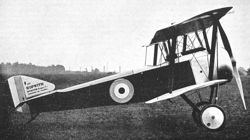
The prototype Sopwith Pup.
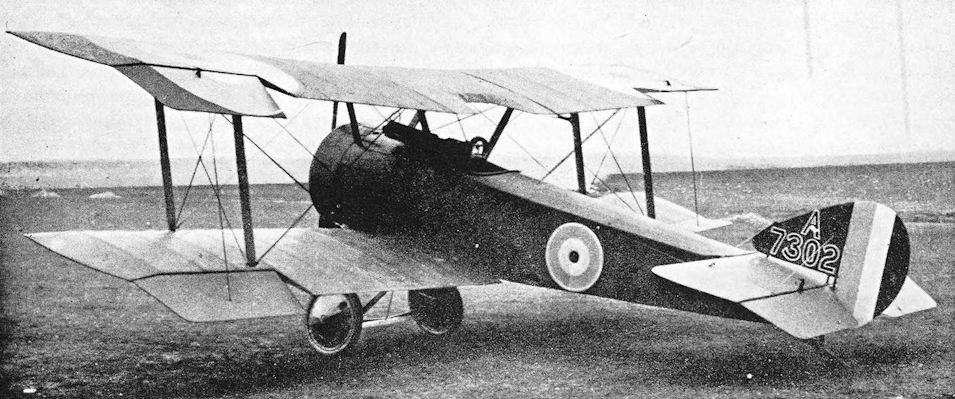
Production Pup, for the R.F.C.
Even with Vickers gun, Sopwith padded screen, and ring sight (and with ailerons awry) the Pup was still one of the daintiest of all aeronautical creations, as A7302 here proves / Loved by those that flew it, the graceful single seat fighter that everyone has come to know as the Sopwith Pup was produced to another of those far-sighted Admiralty requirements, known as the Sopwith Type 9901. First flown during the spring of 1916, the Pup went to France for operational evaluation by RNAS pilots in May 1916, where it was universally acclaimed for its speed and agility. On the basis of this acclaim, both the Admiralty and the War Office placed large orders for the type, with No 8 Squadron of No I Wing, RNAS, receiving the first six production deliveries in late October 1916. The first RFC unit to equip with the Pup was No 54 Squadron, who brought their machines to France on 24 December 1916. Powered by various rotaries of 80hp to 100hp, the Pup was armed with a single, fixed, synchronised .303-inch Vickers. Top level speed of the Pup was 111.5mph at sea level, falling off to 102mph at 10.000 feet. The Pup could climb to 5,000 feet in 5 minutes 20 seconds and 10.000 feet in 14 minutes, while the aircraft's ceiling was 18.500 feet. Used to devastating effect during the Battle of Arras in the spring of 1917, such was the pace of advance in fighter development that the Pup had been rendered obsolescent in front-line terms by the late summer of 1917. Although rapidly supplanted by the Sopwith Triplane in front-line RNAS service, the Pup continued to serve with home defence squadrons, while a RNAS Pup, flown by Flt Sub-Lt B.A. Smart from the cruiser HMS Yarmouth was responsible for the downing of naval Zeppelin L 23, on 1 August 1917. Total Pup build is cited as exceeding 1,800 aircraft when production ended in the autumn of 1918. Pup, serial no A 7302 seen here happens to be the 2nd of 50 late production aircraft built by the Standard Motor Company for the RFC.
Even with Vickers gun, Sopwith padded screen, and ring sight (and with ailerons awry) the Pup was still one of the daintiest of all aeronautical creations, as A7302 here proves / Loved by those that flew it, the graceful single seat fighter that everyone has come to know as the Sopwith Pup was produced to another of those far-sighted Admiralty requirements, known as the Sopwith Type 9901. First flown during the spring of 1916, the Pup went to France for operational evaluation by RNAS pilots in May 1916, where it was universally acclaimed for its speed and agility. On the basis of this acclaim, both the Admiralty and the War Office placed large orders for the type, with No 8 Squadron of No I Wing, RNAS, receiving the first six production deliveries in late October 1916. The first RFC unit to equip with the Pup was No 54 Squadron, who brought their machines to France on 24 December 1916. Powered by various rotaries of 80hp to 100hp, the Pup was armed with a single, fixed, synchronised .303-inch Vickers. Top level speed of the Pup was 111.5mph at sea level, falling off to 102mph at 10.000 feet. The Pup could climb to 5,000 feet in 5 minutes 20 seconds and 10.000 feet in 14 minutes, while the aircraft's ceiling was 18.500 feet. Used to devastating effect during the Battle of Arras in the spring of 1917, such was the pace of advance in fighter development that the Pup had been rendered obsolescent in front-line terms by the late summer of 1917. Although rapidly supplanted by the Sopwith Triplane in front-line RNAS service, the Pup continued to serve with home defence squadrons, while a RNAS Pup, flown by Flt Sub-Lt B.A. Smart from the cruiser HMS Yarmouth was responsible for the downing of naval Zeppelin L 23, on 1 August 1917. Total Pup build is cited as exceeding 1,800 aircraft when production ended in the autumn of 1918. Pup, serial no A 7302 seen here happens to be the 2nd of 50 late production aircraft built by the Standard Motor Company for the RFC.
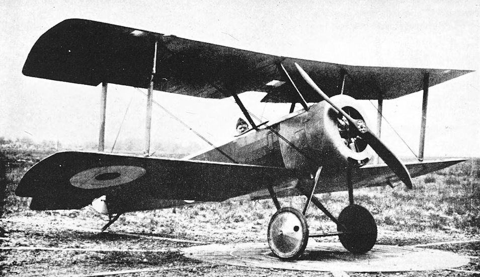
Sopwith Pup with 80 h.p. Gnome engine.
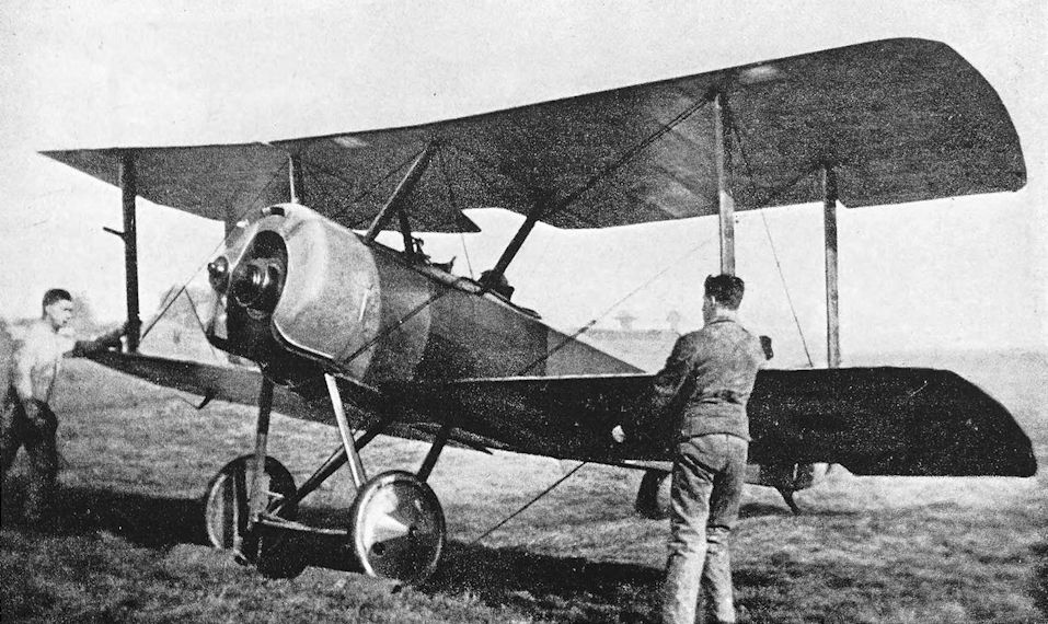
Pup with 100 h.p. Gnome Monosoupape engine.
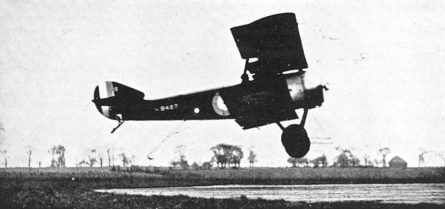
Pup No. 9497 with experimental arrester gear and airscrew guard, landing on dummy deck at the Isle of Grain.
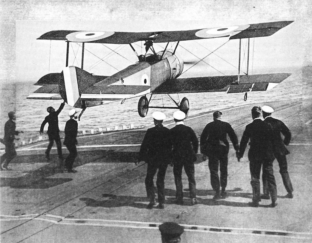
Squadron Commander Dunning lands his Sopwith Pup aboard HMS Furious on 2 August 1917. This was the first carrier landing ever made by an aeroplane. The picture (wherein a light cruiser is crossing the bows distantly) shows the Lewis gun and rope-toggle hand-holds.
AT THE WAR IN THE AIR EXHIBITION: A difficult feat - pilot's bad luck. - The first aeroplane to land on a warship's deck while the vessel is steaming at full speed. - The airman travels at the same speed as the vessel and in the same direction, and manoeuvres so as to drop on a given position. When held by the landing party he stops his engine. This pilot made two successful landings, but was drowned at the third attempt. Great praise is due to the men who volunteered to undertake this dangerous pioneer work, as they knowingly carried their lives in their hands.
AT THE WAR IN THE AIR EXHIBITION: A difficult feat - pilot's bad luck. - The first aeroplane to land on a warship's deck while the vessel is steaming at full speed. - The airman travels at the same speed as the vessel and in the same direction, and manoeuvres so as to drop on a given position. When held by the landing party he stops his engine. This pilot made two successful landings, but was drowned at the third attempt. Great praise is due to the men who volunteered to undertake this dangerous pioneer work, as they knowingly carried their lives in their hands.
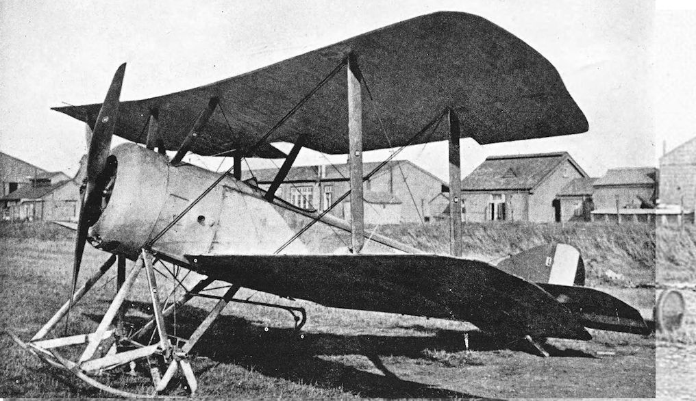
Beardmore-built Pup No.9922 with sprung skid undercarriage and early arrester hook.
Having acclaimed the Pup's daintiness, it is needful here to pre-empt the question 'Whatever happened?' by explaining that the specimen is that described in the text as Pup with sprung skids and short, underslung, forwardly located arrester hook'.
Having acclaimed the Pup's daintiness, it is needful here to pre-empt the question 'Whatever happened?' by explaining that the specimen is that described in the text as Pup with sprung skids and short, underslung, forwardly located arrester hook'.
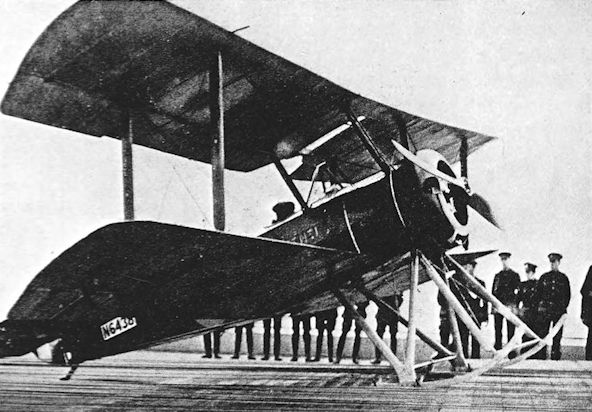
Beardmore-built Pup (Sopwith 9901a) with rigid skid undercarriage on dummy deck. Note the fore-and-aft arrester wires.
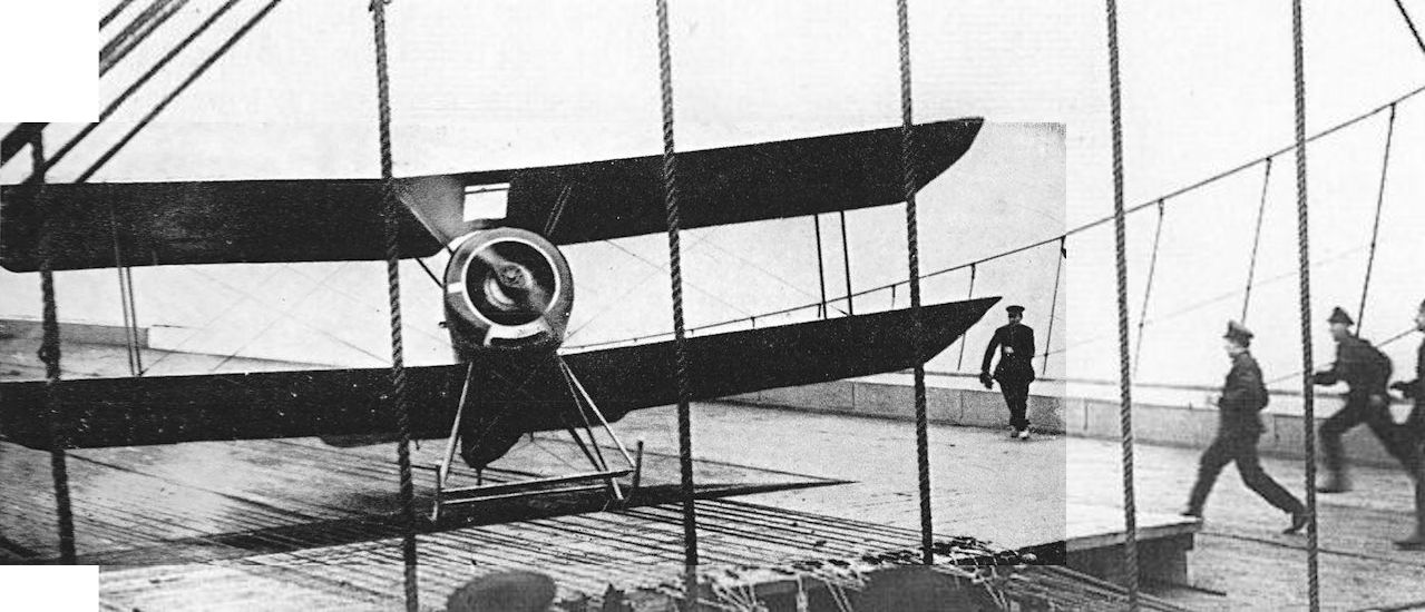
Pup (Sopwith 9901a) with rigid skid undercarriage on H.M.S. Furious.
Pup (N6438) lands on Furious in April 1918.
Pup (N6438) lands on Furious in April 1918.
Sopwith Triplane
THE Sopwith Pup was followed by the Triplane, which was passed by the Sopwith experimental department on May 28th, 1916. Looking back, it is hard to realise the revolutionary nature of the Triplane at the time it appeared. Nothing quite like it had ever been built for military purposes, and the best measure of its success is provided by the profusion of German and Austrian single-seat fighter triplanes which appeared after the impact made by the Sopwith Triplane had earned it a eulogy from General von Hoppner, commander of the German air service.
An astonishing variety of triplanes were built by the A.E.G., Albatros, Austrian Aviatik, Brandenburg, D.F.W., Euler, Fokker, Lohner, Oeffag, Pfalz, Roland, Sablatnig, Schutte-Lanz and W.K.F. concerns; and their very numbers hint at an almost frantic search for the elusive quality, presumably thought to be inherent in the triplane configuration, which made the Sopwith Triplane the fine fighting aeroplane that it was.
It has been said that Anthony Fokker was so anxious to produce an aircraft which would be an adequate reply to the new Sopwith fighter that he resorted to subterfuge to obtain an example of the Triplane. He contrived to arrange for the delivery to his works of the remains of a Sopwith Triplane which had been shot down, despite the fact that the aircraft should have gone to the German experimental field at Adlershof. However, the Fokker Dr. I triplane which was ultimately designed by Reinhold Platz, Fokker’s chief designer, was a very different aeroplane from the Sopwith Triplane.
In the Sopwith type, the triplane layout was adopted in order to give the pilot the widest possible field of vision, and to ensure manoeuvrability. The central wing was level with the pilot’s eyes and obscured very little of his view, and the narrow chord of all the mainplanes ensured that the top and bottom wings interfered less with his outlook than the wings of a biplane. The narrow chord aided manoeuvrability, for the shift of the centre of pressure with changes of incidence was comparatively small; this permitted the use of a short fuselage. At the same time, the distribution of the wing area over three mainplanes kept the span short and conferred a high rate of roll.
The handling qualities of the Triplane were excellent. It is now regarded as only slightly less manoeuvrable than the Pup, but many pilots preferred it to the little biplane.
The fuselage and tail-unit were generally similar to those of the Pup in both appearance and construction, but the structure was stressed to take the 110 h.p. Clerget engine. The wing structure was of considerable interest. Each wing had two main spars, 15 inches apart; those of the upper mainplane were solid, but in the middle and bottom wings they were spindled out between the compression struts. The wings were internally cross-braced with wire.
The most interesting structural feature of the Sopwith Triplane was its interplane bracing. On each side there was only a single broad interplane strut which was continuous from the top wing to the bottom, and passed through a shaped slot in the appropriate compression strut of the middle wing. The centresection struts were similarly continuous from the centre-section to the bottom longerons of the fuselage; the middle wings were secured by means of long pins to special aerofoil-shaped stubs on the centre-section struts. Bracing wires were few: a single landing wire and double flying-wires were fitted on each side, and there were additional drag-wires on the middle wing. Ailerons were fitted to all three mainplanes, and were hinged to the rear spars. The shape of the wing-tips made them similar to those of the Pup, and a similar tailplane was used. Late production Triplanes had a smaller tailplane in which the leading edge was shorter than the trailing edge.
The armament consisted of a single fixed Vickers gun mounted centrally on top of the fuselage and synchronised to fire forward through the airscrew.
The first prototype Sopwith Triplane, N.500, went to France in mid-June, 1916, to undergo Service trials with Naval “A” Fighting Squadron at Furnes. The Triplane was an instant success, and no time was lost in testing it in action, for it was sent up on an interception within a quarter of an hour of its arrival at Furnes.
The type was ordered by the Admiralty for the R.N.A.S., and the War Office followed suit by ordering 266 machines for the R.F.C. As with the Pup, Sopwiths were to build the R.N.A.S. Triplanes, whilst other contractors undertook production of the type for the R.F.C.
After the Battle of the Somme, air fighting increased in intensity, and the balance was not redressed by the transfer of Sopwith 1 1/2-Strutters from the R.N.A.S. to the R.F.C., nor by the loan of R.N.A.S. squadrons to the R.F.C. On November 20th, 1916, Sir Douglas Haig wrote to the War Office and asked for twenty more fighting squadrons. Major-General Trenchard amplified this request at the meeting of the Air Board held on December 11th and, so critical was the situation in France, asked for everything the R.N.A.S. could lend to be handed over to the R.F.C. His specific immediate demands were for four complete R.N.A.S. squadrons, one hundred Rolls-Royce and fifty Hispano-Suiza engines.
The Admiralty complied with as much of this demand as they reasonably could, but suggested that, instead of the fifty Hispano-Suiza engines, they should transfer to the R.F.C. sixty complete Spad S.7s out of their current contract for 120. This offer was accepted with alacrity. In February, 1917, a further agreement was made, under which the R.N.A.S. exchanged all its Spads for all the Sopwith Triplanes then on order for the R.F.C.
Thus it was that the Sopwith Triplane was used operationally by the R.N.A.S. only. In point of fact, all the 266 machines which had been ordered for the R.F.C. were not delivered: it is known that the Clayton and Shuttleworth contract was reduced by 120, and there may have been other reductions.
Deliveries of production Triplanes to the R.N.A.S. had begun late in 1916, and by mid-February, 1917, No. 1 (Naval) Squadron had received sixteen machines. The unit was one of the four R.N.A.S. squadrons which were attached to the R.F.C. in response to Major-General Trenchard’s request, and on February 15th, 1917, it moved from Furnes to Chipilly, where it was attached to the 14th (Army) Wing.
For several weeks the squadron practised formation flying and gunnery, and made its first offensive patrol in early April, 1917. The Battle of Arras began on the 9 th of that month, and aerial fighting reached a pitch which had never previously been experienced. Between April 22nd and May 5th, 1917, the Triplanes of Naval One flew ninety-five offensive patrols, engaged 175 enemy aircraft, destroyed four of them and drove down twelve out of control.
On April 22nd, 1917, two of No.1 (Naval) Squadron’s Triplanes, flown by Flight Commander R. S. Dallas and Flight Sub-Lieutenant T. G. Culling, met an enemy formation of fourteen two-seaters and single-seat fighters. The Germans were flying towards the lines at 16,000 feet. The Triplanes attacked at once, broke up the enemy formation, shot three of them down, and harried the remainder for 45 minutes until the Germans retreated eastward.
By April, 1917, No. 8 (Naval) Squadron also had received Sopwith Triplanes as replacements for its Pups, and in the hands of such pilots as Flight Commander S. J. Goble, D.S.O., D.S.C., Squadron Commander C. Draper, D.S.C., Flight Commander C. D. Booker, D.S.C., Flight Commander R. A. Little and their squadron-mates, the Triplane acquitted itself gloriously.
It was of this period that H. A. Jones wrote in The War in the Air: “The sight of a Sopwith Triplane formation, in particular, induced the enemy pilots to dive out of range.”
The performance of the Triplane had been improved by the installation of the more powerful 130 h.p. Clerget engine. Standard armament continued to be the single Vickers gun, but a small batch of six machines armed with twin Vickers were built by Clayton & Shuttleworth.
After Arras, it was decided to transfer the main Allied effort to the British front in Flanders, and preparations began for the action which became known as the Battle of Messines. On May 15th, 1917, the Eleventh Army Wing was reinforced by the arrival from Dunkerque of No. 10 (Naval) Squadron, equipped with fifteen Sopwith Triplanes. On June 1st, No.1 (Naval) Squadron was transferred from the Third Army.
On June 6th, thirteen of Naval Ten’s Triplanes fought fifteen enemy aeroplanes and shot down five without loss to themselves. Two of the five were Albatros scouts which fell in flames under the fire of Flight Sub-Lieutenant Raymond Collishaw.
Collishaw was probably the best-known exponent of the Sopwith Triplane’s superb fighting qualities. A Canadian, he was given command of “B” Flight of No. io (Naval) Squadron on April ist, 1917. This was the famous “Black Flight”, as redoubtable a fighting unit as took the air during the war: between May and July, 1917, it accounted for no fewer than eighty-seven enemy aircraft. All the pilots were Canadians; the original members were Flight Sub-Lieutenant E. V. Reid, Flight Sub-Lieutenant J. E. Sharman, Flight Sub-Lieutenant G. E. Nash, and Flight Sub-Lieutenant W. M. Alexander. The Triplanes of the Black Flight were named Black Death, Black Maria, Black Roger, Black Prince and Black Sheep.
In a combat on June 26th, 1917, Nash was wounded and forced down behind the enemy lines by Leutnant Allmenroder, a German pilot with thirty victories to his credit. Next day Collishaw avenged the loss of his friend: in a fight which began near Courtrai he shot down and killed Allmenroder, whose green-tailed Albatros crashed on the outskirts of Lille.
In twenty-seven days during June, 1917, Collishaw shot down sixteen enemy machines, of which all save three were Albatros and Halberstadt single-seat fighters.
At the end of August, 1917, No. 10 (Naval) Squadron began to re-equip with Sopwith Camels. Three of its Triplanes were then transferred to No. 1 (Naval) Squadron, which in turn gave up its beloved Triplanes on its withdrawal on November 2nd, 1917. The first Triplane squadrons to begin re-equipment with Camels were No. 8 (Naval), which had received a few Camels by the end of July, 1917, and No. 9 (Naval), which exchanged its Triplanes and Pups for Camels between mid-July and August 4th.
The Battles of Ypres were therefore the last actions over which Sopwith Triplanes flew. They fought with distinction until their final demise.
One Sopwith Triplane, N.5431, was used in Macedonia. It was on the strength of No. 2 Wing R.N.A.S., and in March, 1917, it was allocated to the new R.N.A.S. unit known as “E” Squadron, which later combined with a Royal Flying Corps detachment to form the Composite Fighting Squadron, based at Hadzi Junas as a countermeasure to the German bomber squadron then operating from Hudova. However, N.5431 never reached Hadzi Junas. It flew first to Stavros; and, in company with four 1 1/2- Strutters, set out for Salonika on March 26th, 1917. Its pilot was Flight Lieutenant John Alcock. When landing at Salonika, Alcock made one of the few errors of judgment in his distinguished flying career: he overshot the small aerodrome and wrecked the Triplane. The wreckage was taken back to Mudros and rebuilt: it was still flying from Mudros at the end of September, 1917. On the 30th of that month it was flown by Lieutenant H. T. Mellings when he shot down an enemy single-seat fighter seaplane.
By the end of 1917 the Triplane was no longer a front-line aircraft. Its replacement by the Camel was viewed with mixed feelings by some of the units that had flown it, for it had proved to be a formidable fighter. It combined the manoeuvrability of the Pup with the better performance bestowed by the more powerful engine, yet despite its distinguished record it has always been neglected by historians.
SPECIFICATION
Manufacturers: The Sopwith Aviation Company, Ltd., Canbury Park Road, Kingston-on-Thames.
Other Contractors: Clayton & Shuttleworth, Ltd., Lincoln. Oakley, Ltd., Ilford.
Power: 110 h.p. Clerget; 130 h.p. Clerget.
Dimensions: Span: 26 ft 6 in. Length: 18 ft 10 in. Height: 10 ft 6 in. Chord: 3 ft 3 in. Gap: 3 ft each. Stagger: 1 ft 6 in. Dihedral: 2° 30'. Incidence: 2°. Span of tail: originally 10 ft 1 in., later 8 ft. Wheel track: 5 ft 6 in. Airscrew diameter: 8 ft 11-9 in.
Areas: Wings: top 84 sq ft, middle 72 sq ft, bottom 75 sq ft; total 231 sq ft. Ailerons: each 5-66 sq ft, total 34 sq ft. Tailplane: 14 sq ft. Elevators: 9-6 sq ft. Fin: 3-5 sq ft. Rudder: 4-5 sq ft.
Weights and Performance: Trials conducted at C.F.S.; speed trial on December 9th, 1916, climbing trial on December 7th, 1916. Weights (with 130 h.p. engine): Empty: 1,101 lb. Military load: 80 lb. Pilot: 180 lb. Fuel and oil: 180 lb. Loaded: 1,541 lb. Performance (with 130 h.p. engine): Maximum speed at 5,000 ft: 117 m.p.h.; at 7,000 ft: 112 m.p.h.; at 9,000 ft: 109 m.p.h.; at 11,000 ft: 107 m.p.h.; at 13,000 ft: 104 m.p.h.; at 15,000 ft: 98 m.p.h. Climb to 1,000 ft: 50 sec; to 2,000 ft: 1 min 45 sec; to 3,000 ft: 2 min. 30 sec; to 4,000 ft: 3 min 25 sec; to 5,000 ft: 4 min 35 sec; to 6,000 ft: 5 min 50 sec; to 7,000 ft: 7 min 15 sec; to 8,000 ft: 8 min 40 sec; to 9,000 ft: 10 min 15 sec; to 10,000 ft: 11 min 50 sec; to 11,000 ft: 13 min 35 sec; to 12,000 ft: 15 min 20 sec; to 13,000 ft: 17 min 30 sec; to 14,000 ft: 19 min 50 sec; to 15,000 ft: 22 min 20 sec; to 16,000 ft: 25 min; to 16,400 ft: 26 min 30 sec. Service ceiling: 20,500 ft. Endurance 2 3/4 hours.
Tankage: Petrol: 20 gallons. Oil: 4 gallons.
Armament: One fixed, synchronised Vickers machine-gun mounted centrally on top of the fuselage, firing forward. Several Triplanes had an installation of twin synchronised Vickers guns.
Service Use: Western Front: Naval “A” Fighting Squadron; R.N.A.S. Squadrons Nos. 1, 8, 9, 10 and 12. Macedonia: “E” Squadron, R.N.A.S. Aegean: No. 2 Wing, R.N.A.S., Mudros. Training: R.N.A.S. War School, Manston; R.N.A.S. Port Victoria. Examples of the type went to France, Russia and the U.S.A.
Serial Numbers: The batches A.9000-A.9099 and A.9813-A.9978 were allotted for Triplanes ordered for the R.F.C., but were cancelled. The latter batch was ordered from Clayton & Shuttleworth. N.500: built by Sopwith under Contract No. C.P.117520/16. N.504: built by Sopwith under Contract No. 124352/16. N.524, N.533-N.538: built by Clayton & Shuttleworth under Contract No. A.S.14457. N.541-N.543. N.5350-N.5389: built by Clayton & Shuttleworth. N.5420-N.5494: built by Sopwith. N.5910-N.5934: ordered from Oakley (N.5913-N.5934 were not completed). N.6290-N.6309: built by Sopwith.
Notes on Individual Machines: Used by No. 1 (Naval) Squadron: N.534, N.5364, N.5372, N.5373, N.5377 (later to No. 9 (Naval) Squadron), N.5387 (Aircraft “15”), N.5421 (also used by No. 8 (Naval) Squadron), N.5422, N.5425, N.5426, N.5427, N.5428, N.5432,N-5435,N.5436, N.5437 (later to No. 10 (Naval) Squadron), N.5438, N.5440, N.5441, N.5443, N.5444, N.5445, N.5446, N.5447, N.5451, N.5452, N.5453, N.5454 (“1”), N.5455 (also used by No. 8 (Naval) Squadron), N.5459 (later to No. 9 (Naval) Squadron), N.5461, N.5466 (formerly of No. 10 (Naval) Squadron), N.5472 (“17”), N.5475 (“18”; later to No. 9 (Naval) Squadron), N.5476, N.5479 (“8”), N.5480 (later to No. 10 (Naval) Squadron), N.5484 (later to Nos. 9 and 12 (Naval) Squadrons), N.5485, N.5488, N.5490 (later to Nos. 9 and 10 (Naval) Squadrons), N.5491, N.5494, N.6291 (also used by No. 8 (Naval) Squadron), N.6292 (also used by No. 8 (Naval) Squadron), N.6296, N.6299 (also used by No. 8 (Naval) Squadron), N.6300, N.6303, N.6304 (also used by No. 10 (Naval) Squadron), N.6308, N.6309. Used by No. 8 (Naval) Squadron: N.504, N.5421 (also used by No. 1 (Naval) Squadron), N.5434, N.5442, N.5449, N.5450, N.5455 (a^so used by No. 1 (Naval) Squadron), N.5458 (also used by No. 10 (Naval) Squadron), N.5460, N.5464 (also used by No. 10 (Naval) Squadron), N.5465, N.5468, N.5469, N.5471, N.5472 (also used by No. 1 (Naval) Squadron), N.5474, N.5477, N.5481, N.5482, N.5493 (flown by Flt.-Lt. R. A. Little), N.6290, N.6291 (also used by No. 1 (Naval) Squadron), N.6292 (also used by No. 10 (Naval) Squadron), N.6299 (also used by No. 1 (Naval) Squadron), N.6301. Used by No. 9 (Naval) Squadron: N.5374, N.5377 (formerly of No. 1 (Naval) Squadron), N.5378, N.5459 (formerly of No. 1 (Naval) Squadron), N.5462, N.5475 (formerly of No. 1 (Naval) Squadron), N.5484 (formerly of No. 1 (Naval) Squadron, later to No. 12 (Naval) Squadron), N.5489, N.5490 (formerly used by Nos. 1 and 10 (Naval) Squadrons). Used by No: 10 (Naval) Squadron: N.533, N.5354, N.5355, N.5359, N.5366, N.5367, N.5368, N.5376, N.5380, N.5381, N.5389, N.5429, N.5437 (formerly of No. 1 (Naval) Squadron), N.5458, N.5464, N.5466 (later to No. 1 (Naval) Squadron), N.5478, N.5480 (formerly of No. 1 (Naval) Squadron), N.5483, N.5487, N.5490 (flown by Flt.-Cdr. R. Collishaw; formerly of No. 1 (Naval) Squadron, later to No. 9 (Naval) Squadron), N.5492 (flown by Collishaw), N.6295 (formerly of No. 8 (Naval) Squadron), N.6302, N.6304 (also used by No. 1 (Naval) Squadron), N.6306, N.6307. Used by No. 12 (Naval) Squadron: N.5361, N.5484 (formerly of Nos. 1 and 9 (Naval) Squadrons). Other machines: N.533-N.538 had twin Vickers guns. N.541 and N.542 had been delivered to France, but were returned to the R.N.A.S. N.5385 and N.5388 were sold abroad. N.5424: R.N.A.S. Manston. N.5431: No. 2 Wing R.N.A.S., Mudros, and “E” Squadron.
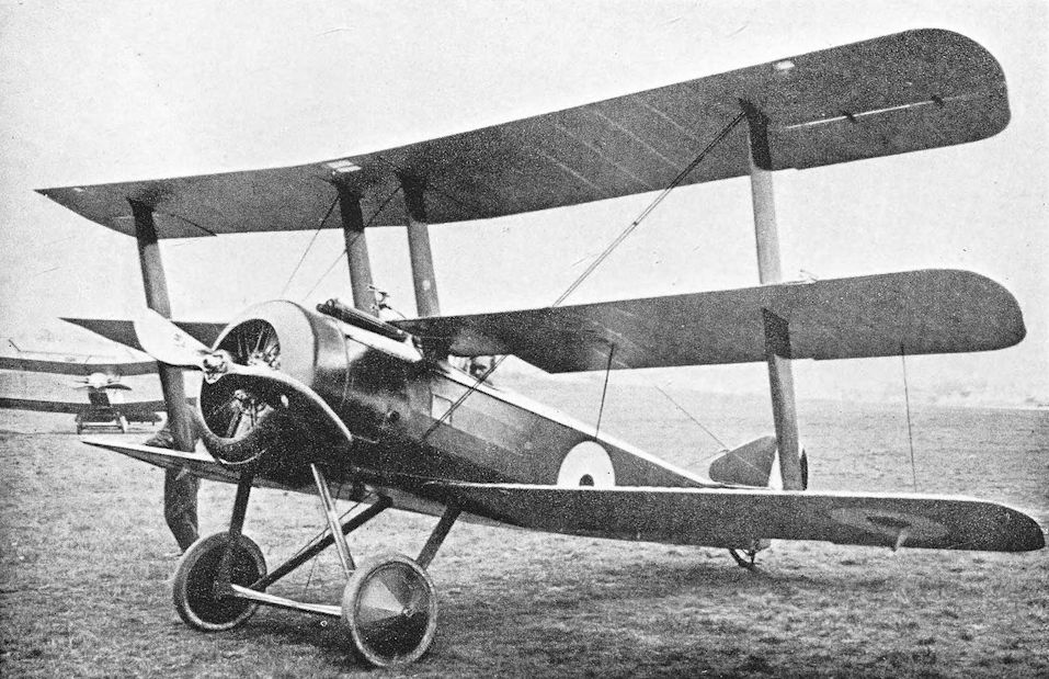
Standard production Sopwith Triplane N5364 went to No.10 (Naval) Squadron, and was lost on July 24 1917, when FSL T C May was shot down and killed by Leutnant Dilthey of Jasta 27

Sopwith Triplane with twin Vickers guns.
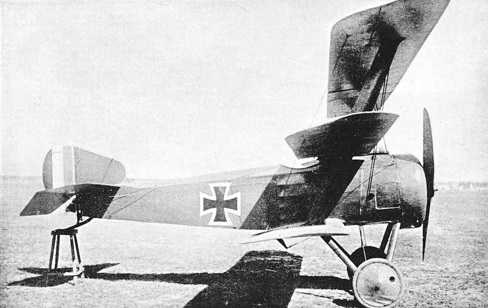
A captured Sopwith Triplane in German hands. The fin is not of standard shape and size.
Sopwith Triplane (Hispano-Suiza Engines)
ALMOST contemporary with the well-known Clerget-powered Sopwith Triplane was another Sopwith single-seat fighter with triplane wings, fitted with a Hispano-Suiza engine. Although the Hispano version has been frequently described as no more than an experimental version of the standard Sopwith Triplane it was in fact a completely different aeroplane, and the only features the two types had in common were the triplane configuration and the “plank” interplane struts.
Whereas the fuselage of the Clerget-powered Triplane had been of similar conception to that of the Pup, the fuselage of the Hispano-powered machine owed more to the 1 1/2-Strutter, and its tail-unit bore a close resemblance to that of the two-seat fighter. In fact, it is not impossible that the design of the Hispano triplane may have been prepared soon after that of the 1 1/2-Strutter, as soon as the nature and potentialities of the Hispano-Suiza engine became known. The first British order for the Hispano-Suiza was placed in August, 1915, but deliveries did not begin until twelve months later. It is therefore possible that the completion of this Sopwith triplane may have been delayed by the lack of an engine of the type for which it had been designed. The power unit of the first Hispano-Suiza triplane was the 150 h.p. direct-drive engine, distinguished by its right-hand airscrew. It was cleanly cowled and had a frontal radiator; at a later stage access panels were provided in the cowling and an outlet for cooling air was made at the rear of the cowling.
A second machine, fitted with the 200 h.p. geared Hispano-Suiza, was built. It had a left-hand airscrew, and the thrust-line was noticeably higher than on the 150 h.p. machine. The cowling retained the access panels and rear outlets which had been introduced on the first machine. The second triplane had a gravity fuel tank in the top centre-section.
The interplane, flying and landing bracing of both Hispano-Suiza triplanes was similar to that of the Clerget-powered machine, but the mainplanes themselves were of different construction and were of wider chord.
The performance, even with the 150 h.p. engine, was good, and the machine might have given a good account of itself as a fighter. However, at the time of its appearance all Hispano-Suiza engines were wanted for S.E.5s, a fact which probably contributed to the abandonment of the Sopwith type.
SPECIFICATION
Manufacturers: The Sopwith Aviation Company, Ltd., Canbury Park Road, Kingston-on-Thames.
Power: 150 h.p. Hispano-Suiza; 200 h.p. Hispano-Suiza.
Dimensions: Span: 28 ft 6 in. Length: 23 ft 2 in. Chord: 4 ft 3 in. Gap: 3 ft 6 in. each. Stagger: 1 ft 6 in. each.
Incidence: 2. Span of tail: 13 ft 6 in. Wheel track: 5 ft 3 in.
Areas: Wings: 340 sq ft. Ailerons: total 49 sq ft. Fin: 3-5 sq ft. Rudder: 7-5 sq ft.
Performance: Maximum speed: 120 m.p.h. Climb to 10,000 ft: 9 min.
Armament: One fixed synchronised Vickers machine-gun mounted centrally on top of the fuselage, firing forward through the airscrew.
Serial Numbers: N.509 (150 h.p. Hispano-Suiza), N.510 (200 h.p. Hispano-Suiza). N.509 was flown at Westgate in the spring of 1917 and was later at Manston, where it was written off on October 29th, 1917. N.510 was at Eastchurch in December, 1916, but was destroyed in a crash there.
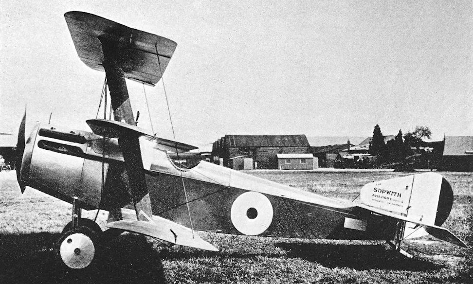
N.509, the Sopwith triplane with 150 h.p. Hispano-Suiza engine.
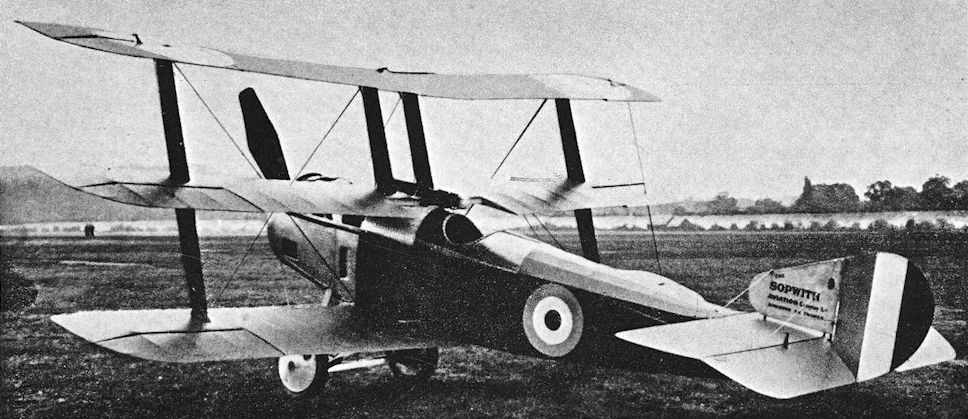
Sopwith triplane N.510 with 200 h.p. Hispano-Suiza engine.
Sopwith Camel
<...>
There are indications that a few F.1 Camels may have been used from ships and even from the towed lighters mentioned later. Be that as it may, another version of the Camel was designed specifically for use from ships, and differed sufficiently from the standard machine to be given a new Sopwith type number: it was the Sopwith 2F.1. The prototype 2F.1, numbered N.5, was tested as early as March, 1917. It was powered by the 130 h.p. Clerget, as were the first production 2F.1s.
The Sopwith 2F.1 was distinguished from the F.1 by a fuselage which was made in two parts: the division occurred one bay behind the cockpit, and at that point the rear portion of the fuselage could be completely detached. The object of the divisible fuselage was, of course, to economise in space on board ship. The necessary modifications to the controls resulted in the appearance of external rocking levers for the elevator controls, immediately behind the division in the fuselage.
The centre-section of the 2F.1 was of shorter span than that of the F. 1, and reduced the overall span of the aircraft by about a foot. The lower mainplanes were correspondingly shorter. The centre-section was supported on steel-tube struts which, in front elevation, were splayed less sharply than the spruce struts of the F.1 Camel; they were noticeably more slender than those of the F.1 and provided a useful distinguishing feature.
One of the more important duties of ship-board fighters of the period was to attack enemy airships, not only those which raided the United Kingdom but those which performed the tactically more important tasks of scouting for and protecting German naval units. For these attacks the R.N.A.S. favoured upward-firing guns, and the armament of the Sopwith 2F.1 was arranged accordingly. A single fixed Vickers gun was mounted on top of the fuselage, to port of centre; and a Lewis gun was carried above the centre-section on a mounting which enabled the weapon to be swung back for reloading and for upward firing. The structure of the centre-section differed from that of the F.1 Camel to permit the gun to pass through the central cut-out.
The Sopwith 2F.1 Camel was flown from ships in the same way as the Pup, which it largely supplanted. A short runway, little more than twice the Camel’s own length, was built on the forecastle of some of the light cruisers, but many had a platform built on top of a gun-turret. A rather longer run was provided on battle cruisers by similar platforms on gun-turrets. In all cases the tail-guide trestle first used for the Sopwith Pup was fitted. The 2F.1 was also flown from the aircraft carriers Furious, Pegasus and, later, Argus and Eagle.
On June 1st, 1918, during one of the sweeps made by the Harwich Force, the Camels of the Australian light cruisers Sydney and Melbourne took off to attack enemy seaplanes: Lieutenant A. C. Sharwood of the Sydney forced one down on the sea, but machine-gun trouble made it impossible for him to follow up his attack. Two Camels from Furious attacked two German seaplanes in the Heligoland Bight during a reconnaissance operation by the First Light Cruiser Squadron on June 17th. Lieutenant G. Heath forced one of the enemy down on the sea; the seaplane was later sunk by the destroyer Valentine.
One of the most daring uses of Sopwith 2F.1 Camels was their operation from lighters towed by destroyers. As is related in the history of the Felixstowe flying boats, these lighters had been developed for the transportation of flying boats across the North Sea in order to increase their radius of action. By using them to carry single-seat fighters the Admiralty was provided with a means of making daylight attacks on Zeppelins over the North Sea and on enemy seaplane bases.
The first attempt to fly a Camel from a lighter was made by Colonel C. R. Samson on May 30th, 1918, and it nearly cost that gallant officer his life. There was no proper flying-off' deck, the take-off device consisting of a pair of troughs running the full length of the lighter. The Camel which Samson used had been specially fitted with twin skids instead of wheels, in the same way as the Sopwith 9901a version of the Pup, and these skids ran in the troughs. Samson resorted to this arrangement partly to enable the experiments to be conducted as quickly as possible, and partly to ensure that his Camel would keep straight and not fall over the side of the lighter before it was properly airborne. The trial was carried out off Orfordness; and on board the towing destroyer Truculent was Lieutenant-Colonel E. D. M. Robertson, the officer commanding Felixstowe Air Station.
With the lighter under tow at 32 knots, Samson started to take off, but the Camel’s skids jumped from the tracks in the lighter’s deck. The machine fell over the bows and was run over by the lighter. Major Egbert Cadbury, D.S.C., D.F.C., was on board the lighter, and his description of what followed appears in these words in The Story of a North Sea Air Station, by C. F. Snowden Gamble (p. 393):
“I gasped, and could not believe it possible that Samson could avoid being battered to atoms. It was all over in a second, and before I had regained my legs, the wreckage of the machine was 300 or 400 yards astern, and no Samson. Suddenly, up bobbed a little white flying cap, and all heaved a sigh of relief.
“An escorting destroyer had got a whaler away in about 30 seconds, and picked him up. He was unhurt, but had had a nasty time under the water disentangling himself from the wires of the wreck. The first thing he said as he ran nimbly up the side of the destroyer was, ‘Well, Robertson, I think it well worth trying again ... ’ ”
On that occasion Major Cadbury had acted as a human tail-guide trestle for Samson’s Camel: he lay on his back and lifted the tail of the machine with his feet.
Despite its premature termination, this first trial provided useful experience, for it showed that the lighter rode stern down when under tow at speed. Since the staging which carried the trackway had been fitted parallel with the water when the lighter was at rest, the Camel had to attempt to take off from what was in effect an uphill runway. A full-size 30-foot flying deck was therefore fitted and was arranged to slope down towards the bows at such an angle that it was horizontal when the lighter was under tow.
The tracks were discarded, and the next test was made with a Camel which had a wheel undercarriage. On July 31st, 1918. Lieutenant S. D. Culley made a successful take-off from the lighter, and the practicability of the scheme was proved.
When the Harwich Force set out for the Heligoland Bight on the evening of August 10th, 1918, three of the destroyers towed lighters carrying flying boats and a fourth (Redoubt) towed a lighter with a Camel on board. The machine’s pilot was again Lieutenant Culley. Early in the morning of August 11 th, the force was off Terschelling, and six coastal motor boats set off in search of enemy vessels. The flying boats were prevented from taking off by a long, smooth swell, the absence of any wind, and an overload of fuel and ammunition.
Soon after the C.M.Bs had started, four German seaplanes appeared and shadowed the Harwich Force for a time; then, just before 8.30 a.m., the Zeppelin L.53 (Kapitanleutnant Prolss) was sighted N.E. of the flotilla at a height of about 15,000 feet. Admiral Tyrwhitt turned his force seawards and laid smoke screens. These manoeuvres sufficed to entice the Zeppelin to follow the ships, and at 8.58 a.m. Culley took off in his Camel. His take-off run on this occasion was but five feet.
At 9.30 a.m., Culley was at 18,000 feet, with the Zeppelin 1,000 feet higher; and at 9.41 a.m. the two craft were approaching each other, the Camel no more than 300 feet below the airship. Culley could climb no higher. He pulled back the control column and fired at the L.53. One of his guns jammed after firing only seven rounds, but the other sent a stream of bullets into the airship. Some seconds later the Zeppelin caught fire, flared up in a great burst of flame, and broke in two. It was the last German airship to be shot down during the war.
Culley had some difficulty in finding the flotilla again and had switched over to his emergency tank before he sighted the British ships. He came down on the water alongside his destroyer; when his Camel was hoisted aboard the lighter it had a pint of petrol in the tank.
Four lighter-borne Camels accompanied the Harwich Force on October 24th, when an attempt was made to attack the German seaplane stations at Borkum and Nordeney. Four flying boats were also taken on lighters, and ten more were flown out from Yarmouth and Felixstowe. The plan miscarried: again it proved impossible for the lighter-borne flying boats to take off, and it was found that three of the Camels could not be flown because the heavy seas coming aboard had damaged their tail-guide trestles.
The most spectacular of the exploits of the carrier-borne 2F.1 Camels had taken place some three months earlier - on July 19th, 1918. It had been decided to attack the Zeppelins in their sheds, for which purpose two special Flights of Camels had been formed and their pilots had been carefully trained for the operation. The Camel Flights embarked in Furious at the end of June, 1918.
The first attempt was abandoned owing to unfavourable weather on June 29th, and Furious and the First Light Cruiser Squadron did not leave Rosyth again until July 17th. A thunderstorm postponed the operation until the 19th. At dawn on that day the carrier was 80 miles N.W. of the German airship base at Tondern, and soon after 3 a.m. the seven Camels were airborne, each carrying two 50-lb bombs. The first Flight of three were flown by Captain W. D. Jackson, Captain F. W. Dickson and Lieutenant N. E. Williams; and the four machines of No. 2 Flight were in the hands of Captain B. A. Smart, Captain T. K. Thyne, Lieutenant S. Dawson, and Lieutenant W. A. Yeulett. (Captain Smart, flying a Sopwith Pup from H.M.S. Yarmouth, had shot down the Zeppelin L.23 on August 21st, 1917.)
Only six Camels reached the objective, for one had been forced down on the water with engine trouble. The bombs of the first Flight struck one of the two airship sheds, and caused a great fire to break out. The shed was destroyed and with it the two Zeppelins it contained, L.54 and L.60. The second Flight of Camels bombed the other shed and damaged it badly, but no other airship was destroyed.
Only two of the Camels, those flown by Dickson and Smart, returned to Furious. Jackson, Williams and one of the other pilots lost their way and had to land in Denmark; Yeulett had to come down on the water and was drowned.
An experimentally modified 2F.1 Camel was at Felixstowe Air Station in 1918. This machine had twin Vickers guns and a special undercarriage made of steel tubes. Each vee was connected across its open end by a length of steel tube, and the structure had the appearance of being jettisonable. Lashing points under the lower wings and rear fuselage hinted at use from lighters, in which case a jettisonable undercarriage would lessen the risk of nosing-over when ditching; for such was the inevitable conclusion of all flights made by the lighter-borne Camels when at sea. Tests were in fact conducted with a Camel which had a jettisonable undercarriage: the aircraft was successfully ditched after its undercarriage had been dropped.
From land stations such as Great Yarmouth the R.N.A.S. used Camels, probably both F.1s and 2F.1s, as fighting escorts for the patrolling Short seaplanes and for anti-submarine patrols. These duties entailed long flights over the sea, and were not accomplished without losses.
In the summer of 1918 it was decided to conduct experiments to provide our own rigid airships with adequate means of defence against enemy aeroplanes. It was intended that an airship should carry with her a single-seat fighter which could be released and flown when the need arose. The first experiments were conducted at Pulham. The airship concerned was the R.23, and the fighter was the Sopwith 2F.1 Camel.
A special horizontal surface was attached to the keel of R.23. The upper wing of the Camel fitted snugly up against this surface, which spanned the distance between the Camel’s interplane struts; and the attachment between aeroplane and airship was made by a quick-release hook which passed through the central cut-out in the Camel’s centre-section. The aeroplane attachment fittings were made by No. 212 Squadron, R.A.F., Great Yarmouth. Camels used in these experiments were N.6622 and N.6814.
The first test was made with a Camel which had its controls locked and a dummy pilot. The release was accomplished satisfactorily, and a live drop was then made by Lieutenant R. E. Keys, D.F.C., of No. 212 Squadron. He was able to start his Camel’s engine after release and flew round the airship before landing safely at Pulham. The Armistice removed the need for such devices and almost eclipsed Keys’ achievement. The Germans subsequently claimed that they had dropped an aeroplane from the Zeppelin L.35 in 1917. Experiments in Britain were abandoned until the end of 1925, but thereafter were not pursued. The Americans used the device on some of their airships in later years.
The 2F.1 Camel remained in service for a time after the Armistice, and at least one continued to fly operationally. Early in 1919, H.M.S. Vindictive was operating in the Baltic during the campaign against the Bolsheviks, and her 2F.1 Camel carried out many patrols over Baltic waters.
The type was used on aircraft carriers in experiments with arrester gear at a time when the arrester cables were longitudinal and had a wooden ramp under their forward ends. As the aircraft ran up the ramp the friction of the cables in the undercarriage hooks increased until the machine was brought to rest. The Camel had three hooks under the spreader bar of the undercarriage, and a special guard was fitted in front of the wheels to prevent damage to the airscrew.
<...>
SPECIFICATION
Manufacturers: The Sopwith Aviation Company, Ltd., Canbury Park Road, Kingston-on-Thames.
Other Contractors: For 2F.1 Camel: Wm. Beardmore & Co., Ltd., Dalmuir, Dumbartonshire; The Fairey Aviation Co., Ltd., Hayes, Middlesex. Pegler & Co., Ltd., Doncaster.
Power: 2F.1 Camel: 130 h.p. Clerget; 150 h.p. B.R.1.
Dimensions: Span: 2F.1, 26 ft 11 in. Length, 2F.1: 130 h.p. Clerget, 18 ft 6 in.; B.R.1, 18 ft 8 in. Height, 2F.1: 9 ft 1 in. Chord: 4 ft 6 in. Gap: at fuselage, 2F.1, 4 ft 11 in. Stagger: at fuselage, 18 in.; at interplane struts, 18 5/16 in. Dihedral: upper, nil; lower (2F.1) 5° 30'. Incidence: 2°. Span of tail: 8 ft 2 1/2 in. Wheel track: 2F.1, 4 ft 5 1/8 in.
Areas: 2F.1: Wings: 221 sq ft.
Tankage: Petrol: main (pressure) tank, 30 gallons; gravity tank, 7 gallons; total, 37 gallons. Oil: 6 1/2 gallons.
Armament: 2F.1 Camel: one fixed, synchronised Vickers machine-gun mounted on top of fuselage to port of centre, firing forward through the airscrew. One Lewis gun on Admiralty top plane mounting above centre-section. At least one 2F.1 of the R.N.A.S. Station, Felixstowe, had twin Vickers guns as on the F.1 Camel. The 2F.1 Camels which bombed Tondern each carried two 50-lb bombs.
Service Use: 2F.1 Camel: aircraft carriers Argus, Furious, Pegasus and Eagle. Battle cruisers Barham, Repulse, Renown, Australia, New Zealand, Inflexible, Indomitable, Tiger, Princess Royal, Lion. Large light cruisers Glorious, Courageous, Vindictive. Light cruisers Caledon, Calliope, Cassandra, Cordelia, Dublin, Birkenhead, Southampton, Chatham, Galatea, Melbourne, Sydney, Phaeton, Royalist and Tarmouth. Flown from lighters towed by destroyers of the Harwich Force. Used at some shore stations of the R.N.A.S., e.g. Great Yarmouth, Manston, Port Victoria, Cranwell, Donibristle.
Production and Allocation: A total of 5,490 Camels were built: 1,325 in 1917 and 4,165 in 1918. Of the 4,188 machines which were distributed to units of the R.F.C. and R.A.F., 2,116 went to squadrons with the B.E.F. in France; twenty-four went to the Independent Force; 145 to squadrons with the Dover-Dunkerque Command; 218 to Italy; seventy-two to units in the Mediterranean; fifty-seven to the Middle East Brigade; 377 to Home Defence squadrons; and 1,1.79 to training units. In 1918, thirty-six Camels were supplied to Belgium and six to Greece. The American Expeditionary Force purchased 143 Camels in June, 1918.
Camels on Charge of the R.A.F. on October 31st, 1918:
F.1 Camel F.1 Camel F.1 Camel F.1 Camel 2F.1
Clerget Le Rhone and Monosoupape B.R.1 Total -
Expeditionary Force, France 344 272 186 802 -
Independent Force, France 27 - - 27 -
Italy 75 - - 75 -
Mediterranean 100 - - 100 6
Dover-Dunkerque Command 12 - 24 36 -
Home Defence units - 181 - 181 -
Training units 142 3 1 146 2
Other units in U.K. 355 39 34 428 8
Egypt and Palestine - 9 - 9 -
Macedonia - 11 - 11 -
Mesopotamia - 11 - 11 -
En route to Middle East 26 25 - 51 -
With units of the Grand Fleet 4 10 26 40 112
Aeroplane Repair Depots 72 14 1 87 -
In store 160 127 84 371 -
Aircraft Acceptance Parks 25 119 - 144 1
Totals 1,342 821 356 2,519 129
Serial Numbers: 2F.1 Camel: N.5 (prototype). N.6600-N.6649. N.6750-N.6799. N.6800-N.6849. N.7100-N.7149: built by Beardmore. N.7200-N.7299: ordered from the Fairey Aviation Co., but contract cancelled. N.7300-N.7349: ordered from Pegler but contract cancelled. Between and about N.7357-N.7369 (probable batch N.7350-N.7399). N.8151-N.8156 and N.8204 are known to have been 2F.1 Camels.
Costs:
Sopwith 2F.1 airframe without engine, instruments and guns £825 0s.
<...>
There are indications that a few F.1 Camels may have been used from ships and even from the towed lighters mentioned later. Be that as it may, another version of the Camel was designed specifically for use from ships, and differed sufficiently from the standard machine to be given a new Sopwith type number: it was the Sopwith 2F.1. The prototype 2F.1, numbered N.5, was tested as early as March, 1917. It was powered by the 130 h.p. Clerget, as were the first production 2F.1s.
The Sopwith 2F.1 was distinguished from the F.1 by a fuselage which was made in two parts: the division occurred one bay behind the cockpit, and at that point the rear portion of the fuselage could be completely detached. The object of the divisible fuselage was, of course, to economise in space on board ship. The necessary modifications to the controls resulted in the appearance of external rocking levers for the elevator controls, immediately behind the division in the fuselage.
The centre-section of the 2F.1 was of shorter span than that of the F. 1, and reduced the overall span of the aircraft by about a foot. The lower mainplanes were correspondingly shorter. The centre-section was supported on steel-tube struts which, in front elevation, were splayed less sharply than the spruce struts of the F.1 Camel; they were noticeably more slender than those of the F.1 and provided a useful distinguishing feature.
One of the more important duties of ship-board fighters of the period was to attack enemy airships, not only those which raided the United Kingdom but those which performed the tactically more important tasks of scouting for and protecting German naval units. For these attacks the R.N.A.S. favoured upward-firing guns, and the armament of the Sopwith 2F.1 was arranged accordingly. A single fixed Vickers gun was mounted on top of the fuselage, to port of centre; and a Lewis gun was carried above the centre-section on a mounting which enabled the weapon to be swung back for reloading and for upward firing. The structure of the centre-section differed from that of the F.1 Camel to permit the gun to pass through the central cut-out.
The Sopwith 2F.1 Camel was flown from ships in the same way as the Pup, which it largely supplanted. A short runway, little more than twice the Camel’s own length, was built on the forecastle of some of the light cruisers, but many had a platform built on top of a gun-turret. A rather longer run was provided on battle cruisers by similar platforms on gun-turrets. In all cases the tail-guide trestle first used for the Sopwith Pup was fitted. The 2F.1 was also flown from the aircraft carriers Furious, Pegasus and, later, Argus and Eagle.
On June 1st, 1918, during one of the sweeps made by the Harwich Force, the Camels of the Australian light cruisers Sydney and Melbourne took off to attack enemy seaplanes: Lieutenant A. C. Sharwood of the Sydney forced one down on the sea, but machine-gun trouble made it impossible for him to follow up his attack. Two Camels from Furious attacked two German seaplanes in the Heligoland Bight during a reconnaissance operation by the First Light Cruiser Squadron on June 17th. Lieutenant G. Heath forced one of the enemy down on the sea; the seaplane was later sunk by the destroyer Valentine.
One of the most daring uses of Sopwith 2F.1 Camels was their operation from lighters towed by destroyers. As is related in the history of the Felixstowe flying boats, these lighters had been developed for the transportation of flying boats across the North Sea in order to increase their radius of action. By using them to carry single-seat fighters the Admiralty was provided with a means of making daylight attacks on Zeppelins over the North Sea and on enemy seaplane bases.
The first attempt to fly a Camel from a lighter was made by Colonel C. R. Samson on May 30th, 1918, and it nearly cost that gallant officer his life. There was no proper flying-off' deck, the take-off device consisting of a pair of troughs running the full length of the lighter. The Camel which Samson used had been specially fitted with twin skids instead of wheels, in the same way as the Sopwith 9901a version of the Pup, and these skids ran in the troughs. Samson resorted to this arrangement partly to enable the experiments to be conducted as quickly as possible, and partly to ensure that his Camel would keep straight and not fall over the side of the lighter before it was properly airborne. The trial was carried out off Orfordness; and on board the towing destroyer Truculent was Lieutenant-Colonel E. D. M. Robertson, the officer commanding Felixstowe Air Station.
With the lighter under tow at 32 knots, Samson started to take off, but the Camel’s skids jumped from the tracks in the lighter’s deck. The machine fell over the bows and was run over by the lighter. Major Egbert Cadbury, D.S.C., D.F.C., was on board the lighter, and his description of what followed appears in these words in The Story of a North Sea Air Station, by C. F. Snowden Gamble (p. 393):
“I gasped, and could not believe it possible that Samson could avoid being battered to atoms. It was all over in a second, and before I had regained my legs, the wreckage of the machine was 300 or 400 yards astern, and no Samson. Suddenly, up bobbed a little white flying cap, and all heaved a sigh of relief.
“An escorting destroyer had got a whaler away in about 30 seconds, and picked him up. He was unhurt, but had had a nasty time under the water disentangling himself from the wires of the wreck. The first thing he said as he ran nimbly up the side of the destroyer was, ‘Well, Robertson, I think it well worth trying again ... ’ ”
On that occasion Major Cadbury had acted as a human tail-guide trestle for Samson’s Camel: he lay on his back and lifted the tail of the machine with his feet.
Despite its premature termination, this first trial provided useful experience, for it showed that the lighter rode stern down when under tow at speed. Since the staging which carried the trackway had been fitted parallel with the water when the lighter was at rest, the Camel had to attempt to take off from what was in effect an uphill runway. A full-size 30-foot flying deck was therefore fitted and was arranged to slope down towards the bows at such an angle that it was horizontal when the lighter was under tow.
The tracks were discarded, and the next test was made with a Camel which had a wheel undercarriage. On July 31st, 1918. Lieutenant S. D. Culley made a successful take-off from the lighter, and the practicability of the scheme was proved.
When the Harwich Force set out for the Heligoland Bight on the evening of August 10th, 1918, three of the destroyers towed lighters carrying flying boats and a fourth (Redoubt) towed a lighter with a Camel on board. The machine’s pilot was again Lieutenant Culley. Early in the morning of August 11 th, the force was off Terschelling, and six coastal motor boats set off in search of enemy vessels. The flying boats were prevented from taking off by a long, smooth swell, the absence of any wind, and an overload of fuel and ammunition.
Soon after the C.M.Bs had started, four German seaplanes appeared and shadowed the Harwich Force for a time; then, just before 8.30 a.m., the Zeppelin L.53 (Kapitanleutnant Prolss) was sighted N.E. of the flotilla at a height of about 15,000 feet. Admiral Tyrwhitt turned his force seawards and laid smoke screens. These manoeuvres sufficed to entice the Zeppelin to follow the ships, and at 8.58 a.m. Culley took off in his Camel. His take-off run on this occasion was but five feet.
At 9.30 a.m., Culley was at 18,000 feet, with the Zeppelin 1,000 feet higher; and at 9.41 a.m. the two craft were approaching each other, the Camel no more than 300 feet below the airship. Culley could climb no higher. He pulled back the control column and fired at the L.53. One of his guns jammed after firing only seven rounds, but the other sent a stream of bullets into the airship. Some seconds later the Zeppelin caught fire, flared up in a great burst of flame, and broke in two. It was the last German airship to be shot down during the war.
Culley had some difficulty in finding the flotilla again and had switched over to his emergency tank before he sighted the British ships. He came down on the water alongside his destroyer; when his Camel was hoisted aboard the lighter it had a pint of petrol in the tank.
Four lighter-borne Camels accompanied the Harwich Force on October 24th, when an attempt was made to attack the German seaplane stations at Borkum and Nordeney. Four flying boats were also taken on lighters, and ten more were flown out from Yarmouth and Felixstowe. The plan miscarried: again it proved impossible for the lighter-borne flying boats to take off, and it was found that three of the Camels could not be flown because the heavy seas coming aboard had damaged their tail-guide trestles.
The most spectacular of the exploits of the carrier-borne 2F.1 Camels had taken place some three months earlier - on July 19th, 1918. It had been decided to attack the Zeppelins in their sheds, for which purpose two special Flights of Camels had been formed and their pilots had been carefully trained for the operation. The Camel Flights embarked in Furious at the end of June, 1918.
The first attempt was abandoned owing to unfavourable weather on June 29th, and Furious and the First Light Cruiser Squadron did not leave Rosyth again until July 17th. A thunderstorm postponed the operation until the 19th. At dawn on that day the carrier was 80 miles N.W. of the German airship base at Tondern, and soon after 3 a.m. the seven Camels were airborne, each carrying two 50-lb bombs. The first Flight of three were flown by Captain W. D. Jackson, Captain F. W. Dickson and Lieutenant N. E. Williams; and the four machines of No. 2 Flight were in the hands of Captain B. A. Smart, Captain T. K. Thyne, Lieutenant S. Dawson, and Lieutenant W. A. Yeulett. (Captain Smart, flying a Sopwith Pup from H.M.S. Yarmouth, had shot down the Zeppelin L.23 on August 21st, 1917.)
Only six Camels reached the objective, for one had been forced down on the water with engine trouble. The bombs of the first Flight struck one of the two airship sheds, and caused a great fire to break out. The shed was destroyed and with it the two Zeppelins it contained, L.54 and L.60. The second Flight of Camels bombed the other shed and damaged it badly, but no other airship was destroyed.
Only two of the Camels, those flown by Dickson and Smart, returned to Furious. Jackson, Williams and one of the other pilots lost their way and had to land in Denmark; Yeulett had to come down on the water and was drowned.
An experimentally modified 2F.1 Camel was at Felixstowe Air Station in 1918. This machine had twin Vickers guns and a special undercarriage made of steel tubes. Each vee was connected across its open end by a length of steel tube, and the structure had the appearance of being jettisonable. Lashing points under the lower wings and rear fuselage hinted at use from lighters, in which case a jettisonable undercarriage would lessen the risk of nosing-over when ditching; for such was the inevitable conclusion of all flights made by the lighter-borne Camels when at sea. Tests were in fact conducted with a Camel which had a jettisonable undercarriage: the aircraft was successfully ditched after its undercarriage had been dropped.
From land stations such as Great Yarmouth the R.N.A.S. used Camels, probably both F.1s and 2F.1s, as fighting escorts for the patrolling Short seaplanes and for anti-submarine patrols. These duties entailed long flights over the sea, and were not accomplished without losses.
In the summer of 1918 it was decided to conduct experiments to provide our own rigid airships with adequate means of defence against enemy aeroplanes. It was intended that an airship should carry with her a single-seat fighter which could be released and flown when the need arose. The first experiments were conducted at Pulham. The airship concerned was the R.23, and the fighter was the Sopwith 2F.1 Camel.
A special horizontal surface was attached to the keel of R.23. The upper wing of the Camel fitted snugly up against this surface, which spanned the distance between the Camel’s interplane struts; and the attachment between aeroplane and airship was made by a quick-release hook which passed through the central cut-out in the Camel’s centre-section. The aeroplane attachment fittings were made by No. 212 Squadron, R.A.F., Great Yarmouth. Camels used in these experiments were N.6622 and N.6814.
The first test was made with a Camel which had its controls locked and a dummy pilot. The release was accomplished satisfactorily, and a live drop was then made by Lieutenant R. E. Keys, D.F.C., of No. 212 Squadron. He was able to start his Camel’s engine after release and flew round the airship before landing safely at Pulham. The Armistice removed the need for such devices and almost eclipsed Keys’ achievement. The Germans subsequently claimed that they had dropped an aeroplane from the Zeppelin L.35 in 1917. Experiments in Britain were abandoned until the end of 1925, but thereafter were not pursued. The Americans used the device on some of their airships in later years.
The 2F.1 Camel remained in service for a time after the Armistice, and at least one continued to fly operationally. Early in 1919, H.M.S. Vindictive was operating in the Baltic during the campaign against the Bolsheviks, and her 2F.1 Camel carried out many patrols over Baltic waters.
The type was used on aircraft carriers in experiments with arrester gear at a time when the arrester cables were longitudinal and had a wooden ramp under their forward ends. As the aircraft ran up the ramp the friction of the cables in the undercarriage hooks increased until the machine was brought to rest. The Camel had three hooks under the spreader bar of the undercarriage, and a special guard was fitted in front of the wheels to prevent damage to the airscrew.
<...>
SPECIFICATION
Manufacturers: The Sopwith Aviation Company, Ltd., Canbury Park Road, Kingston-on-Thames.
Other Contractors: For 2F.1 Camel: Wm. Beardmore & Co., Ltd., Dalmuir, Dumbartonshire; The Fairey Aviation Co., Ltd., Hayes, Middlesex. Pegler & Co., Ltd., Doncaster.
Power: 2F.1 Camel: 130 h.p. Clerget; 150 h.p. B.R.1.
Dimensions: Span: 2F.1, 26 ft 11 in. Length, 2F.1: 130 h.p. Clerget, 18 ft 6 in.; B.R.1, 18 ft 8 in. Height, 2F.1: 9 ft 1 in. Chord: 4 ft 6 in. Gap: at fuselage, 2F.1, 4 ft 11 in. Stagger: at fuselage, 18 in.; at interplane struts, 18 5/16 in. Dihedral: upper, nil; lower (2F.1) 5° 30'. Incidence: 2°. Span of tail: 8 ft 2 1/2 in. Wheel track: 2F.1, 4 ft 5 1/8 in.
Areas: 2F.1: Wings: 221 sq ft.
Tankage: Petrol: main (pressure) tank, 30 gallons; gravity tank, 7 gallons; total, 37 gallons. Oil: 6 1/2 gallons.
Armament: 2F.1 Camel: one fixed, synchronised Vickers machine-gun mounted on top of fuselage to port of centre, firing forward through the airscrew. One Lewis gun on Admiralty top plane mounting above centre-section. At least one 2F.1 of the R.N.A.S. Station, Felixstowe, had twin Vickers guns as on the F.1 Camel. The 2F.1 Camels which bombed Tondern each carried two 50-lb bombs.
Service Use: 2F.1 Camel: aircraft carriers Argus, Furious, Pegasus and Eagle. Battle cruisers Barham, Repulse, Renown, Australia, New Zealand, Inflexible, Indomitable, Tiger, Princess Royal, Lion. Large light cruisers Glorious, Courageous, Vindictive. Light cruisers Caledon, Calliope, Cassandra, Cordelia, Dublin, Birkenhead, Southampton, Chatham, Galatea, Melbourne, Sydney, Phaeton, Royalist and Tarmouth. Flown from lighters towed by destroyers of the Harwich Force. Used at some shore stations of the R.N.A.S., e.g. Great Yarmouth, Manston, Port Victoria, Cranwell, Donibristle.
Production and Allocation: A total of 5,490 Camels were built: 1,325 in 1917 and 4,165 in 1918. Of the 4,188 machines which were distributed to units of the R.F.C. and R.A.F., 2,116 went to squadrons with the B.E.F. in France; twenty-four went to the Independent Force; 145 to squadrons with the Dover-Dunkerque Command; 218 to Italy; seventy-two to units in the Mediterranean; fifty-seven to the Middle East Brigade; 377 to Home Defence squadrons; and 1,1.79 to training units. In 1918, thirty-six Camels were supplied to Belgium and six to Greece. The American Expeditionary Force purchased 143 Camels in June, 1918.
Camels on Charge of the R.A.F. on October 31st, 1918:
F.1 Camel F.1 Camel F.1 Camel F.1 Camel 2F.1
Clerget Le Rhone and Monosoupape B.R.1 Total -
Expeditionary Force, France 344 272 186 802 -
Independent Force, France 27 - - 27 -
Italy 75 - - 75 -
Mediterranean 100 - - 100 6
Dover-Dunkerque Command 12 - 24 36 -
Home Defence units - 181 - 181 -
Training units 142 3 1 146 2
Other units in U.K. 355 39 34 428 8
Egypt and Palestine - 9 - 9 -
Macedonia - 11 - 11 -
Mesopotamia - 11 - 11 -
En route to Middle East 26 25 - 51 -
With units of the Grand Fleet 4 10 26 40 112
Aeroplane Repair Depots 72 14 1 87 -
In store 160 127 84 371 -
Aircraft Acceptance Parks 25 119 - 144 1
Totals 1,342 821 356 2,519 129
Serial Numbers: 2F.1 Camel: N.5 (prototype). N.6600-N.6649. N.6750-N.6799. N.6800-N.6849. N.7100-N.7149: built by Beardmore. N.7200-N.7299: ordered from the Fairey Aviation Co., but contract cancelled. N.7300-N.7349: ordered from Pegler but contract cancelled. Between and about N.7357-N.7369 (probable batch N.7350-N.7399). N.8151-N.8156 and N.8204 are known to have been 2F.1 Camels.
Costs:
Sopwith 2F.1 airframe without engine, instruments and guns £825 0s.

Experimental 2F.1 at Felixstowe with twin Vickers guns and steel-tube undercarriage.

Both guns are clearly installed on the Beardmore-built N7136, seen here at Dalmuir. Note also the external elevator-control cables, running from the lever just behind the fuselage joint.

The picture is of Lt S.D. Culley, RN, during the first successful tow lighter demonstration, made on 31 July 1918. Here it should be recalled that Cdr Samson had nearly lost his life attempting this feat some weeks earlier, when his Camel snagged some ties during launch.
A reminder that the 2F.1 Camel was developed essentially for Naval use with seaborne forces, and epitomising also the glorious victory by Lieut Stuart Culley over Zeppelin L53 just before the Armistice. (A reminder also that although the 2F.1 was operated from 'real' aircraft-carriers it was not a true deck-landing aircraft, as were its successors, though like other Sopwiths, it helped to show the way).
A reminder that the 2F.1 Camel was developed essentially for Naval use with seaborne forces, and epitomising also the glorious victory by Lieut Stuart Culley over Zeppelin L53 just before the Armistice. (A reminder also that although the 2F.1 was operated from 'real' aircraft-carriers it was not a true deck-landing aircraft, as were its successors, though like other Sopwiths, it helped to show the way).

Arrester-gear hooks and airscrew guard on Sopwith 2F.1 for use on aircraft carriers.

Sopwith 2F.1, serial number N.6814, slung under H.M. Airship R.23.
An element extra to those named in an earlier caption is implicit here, with N6814 snugly stowed beneath the airship R23 for tests connected with air-launching.
An element extra to those named in an earlier caption is implicit here, with N6814 snugly stowed beneath the airship R23 for tests connected with air-launching.
Sopwith B.1
THE single-seat bomber version of the Sopwith 1 1/2-Strutter enjoyed a fair measure of success, and it was a natural development for the Sopwith company to produce a more powerful single-seat aeroplane designed specifically as a bomber.
In the spring of 1917 the Sopwith B.1 appeared. It was contemporary with the Sopwith T.1 and, like the torpedo-carrier, was required to lift a substantial load. It is hardly surprising, therefore, that the two aircraft resembled each other quite closely.
Both had the 200 h.p. Hispano-Suiza engine, and the engine cowlings were very similar. In the B.1, however, the pilot sat directly under the centre-section in order to have a good forward and downward view for bombing. The bombs were stowed vertically within the fuselage; the bomb cell was in the fuselage bay just behind the rear centre-section struts. Construction was conventional and typical of the period.
A plain vee undercarriage of typical Sopwith design was used: each wheel was mounted on a steeltube half-axle which could move vertically in guides at the apex of each vee-strut against the tension of several coils of rubber cord.
The mainplanes were of equal span and had two bays of interplane struts. Ailerons were fitted to upper and lower wings. The tail-unit was indistinguishable in appearance from that of the Sopwith T.1, and on the first B.1 the control cables to rudder and elevators were carried internally for the greater part of their length.
Performance trials of the B.1 were carried out in April, 1917,and,with a bomb load of 560 lb, excellent results were obtained, both for level speed and rate of climb. For Service trials, a Sopwith B.1 was sent to the R.N.A.S. Fifth Wing at Dunkerque and participated in bombing raids in company with the Wing’s D.H.4s. While it was operational, the B.1 was armed with a single synchronised Lewis gun firing forward through the airscrew.
The Sopwith B.1 was not adopted by the R.N.A.S., however. About the autumn of 1917, a B.1 airframe was delivered to the Experimental Construction Depot, Port Victoria, for conversion into a two- seat Fleet reconnaissance machine. Surprise was expressed that it had not been adopted as a bomber, and subsequent accounts give the impression that aileron control was deficient. However, that criticism more probably applied to the first modified form in which the aircraft flew at Port Victoria, for an official report on the Sopwith B.1 is as follows:
“This machine was tail-heavy with full bomb-load, and nose-heavy when light in spite of full tailplane adjustment. Considerable left rudder is needed at full speed and this combined with the longitudinal heaviness made the machine tiring to fly. Controllability in air and on ground very good.”
The ultimate product of the E.C.D.’s conversion was the Grain Griffin, but much experimental work had to be done in order to make its ailerons effective.
A slightly modified version of the Sopwith B.1 existed in 1918, and may have been the machine which was tested in May of that year. Numbered B.1496, this B.1 had its elevator cables wholly external from rocking-levers outside the cockpit.
SPECIFICATION
Manufacturers: The Sopwith Aviation Company, Ltd., Canbury Park Road, Kingston-on-Thames.
Power: 200 h.p. Hispano-Suiza.
Weights (lb) and Performance:
Bomb load Nil Twenty 28-lb Analyte bombs 560 lb
No. of Trial Report - M.94 M.195
Date of Trial Report - April, 1917 May, 1918
Type of airscrew used on. trial Lang 3280 Lang 3280 Lang 5150
Weight empty 1,700 1,700 -
Military load Nil 560 560
Pilot 180 180 180
Fuel and oil 237 505 -
Weight loaded 2,1 17 2,945 3,035
Maximum speed (m.p.h.) at
10,000 ft - 118-5 110
15,000 ft 112 97-5 98-5
17,000 ft 105 - -
m. s. m. s. m. s.
Climb to
1,000 ft - - 1 12 - -
6,500 ft 4 42 8 54 9 10
10,000 ft 7 54 15 30 16 25
12,000 ft - - 20 12 - -
14,000 ft - - 26 06 - -
15,000 ft 13 54 29 36 34 10
17,000 ft 17 24 - - - -
Service ceiling (feet) - 19,000 17,000
Endurance (hours) - 3 3/4 -
Dimensions: Span: 38 ft 6 in. Length: 27 ft. Height: 9 ft 6 in. Chord: 6 ft 3 in. Gap: 6 ft. Dihedral: 2° 30'.
Incidence: 2°. Span of tail: 11 ft 6 in. Wheel track: 5 ft. Tyres: 750 X 125 mm. Airscrew diameter: 10 ft.
Areas: Wings: 460 sq ft. Ailerons: total 66-5 sq ft. Tailplane: 35-5 sq ft. Elevators: 18-5 sq ft. Fin: 4 sq ft. Rudder: 8 sq ft.
Tankage: Petrol: 56 gallons. Oil: 9 gallons.
Armament: A bomb-load of 560 lb could be carried. One fixed Lewis machine-gun was mounted centrally on top of the engine cowling, and was synchronised to fire forward through the airscrew.
Service Use: R.N.A.S. Fifth Wing, Dunkerque.
Serial Number: B.1496. (The Sopwith B.1 which was tested in April, 1917, was built under Licence No. 6, and was fitted with engine No. 7245 13C.)

Possibly taken on the same occasion as the preceding front view (though the propeller is differently angled) this picture of the original B.1 gives the false impression - due to an optical illusion - that the upper-starboard aileron has a balancing surface.

The Sopwith B.1, serial number B.1496, with modified elevator controls.
The Sopwith B.I with D.H.4s of the R.N.A.S. Fifth Wing at Coudekerque.
Sopwith Bee
THIS tiny biplane was a “one-off”, built specially for Harry Hawker by whom it was used for aerobatic displays. It was a simple single-bay biplane powered by a 50 h.p. Gnome rotary engine. Although usually known as the Sopwith Bee, it was sometimes referred to as the Tadpole.
The upper wing was set low above the fuselage and there was a cut-out in the centre-section to accommodate the pilot’s head. Perhaps the most remarkable feature of the Bee was the use of wing-warping in place of ailerons, but it was probably thought desirable to make the machine as simple as possible, mechanically and structurally.
The airframe embodied a number of Pup components, including the undercarriage, but the Bee did not resemble the Pup in any way. The tail-unit, which incorporated a horn-balanced rudder, more nearly resembled that of the Dolphin than any other Sopwith type.
At a late stage of its existence the Bee was fitted with a Vickers gun and was tested as a light fighting scout. In this guise it must have been directly comparable to the Port Victoria P.V.7 and P.V.8; but no Service development took place.
SPECIFICATION
Manufacturers: The Sopwith Aviation Company, Ltd., Canbury Park Road, Kingston-on-Thames.
Power: 50 h.p. Gnome.
Dimensions: Span: 16 ft 3 in. Length: 14 ft 3 in.
Armament: One Vickers machine-gun.

Sopwith Bee.
Sopwith T.1 Cuckoo
THAT ardent pioneer protagonist of naval aviation, Commodore (later Rear Admiral Sir) Murray Sueter, was the originator of the idea of torpedo-carrying landplanes operating from aircraft carriers.
Up to October, 1916, the R.N.A.S. had used only seaplanes as torpedo-carriers, and the frail and somewhat primitive nature of the early machines detracted from their performance in that capacity. Commodore Sueter was rightly convinced of the value of torpedo-carrying aircraft, and was anxious to find an alternative means of getting torpedoes into the air.
Early in October, 1916, he invited Mr (later Sir) Thomas Sopwith to the Admiralty in order to discuss the idea, and the outcome of their conversation was confirmed by Commodore Sueter in his Most Secret memorandum of October 9th, 1916. In it he asked Mr Sopwith to investigate the possibility of building torpedo-carrying aircraft capable of carrying either one or two 1,000-lb torpedoes and four hours’ fuel. The memorandum envisaged the probable use of a catapult to launch the aircraft, quite a remarkable thought at a time when no British aircraft catapult existed.
Mr Sopwith thought the requirements would not be easy to fulfil, but finally his company produced a design for a single-engined single-seat biplane capable of carrying one 1,000-Ib torpedo. The aircraft was designated Sopwith T.1.
Although preceded in point of time by Germany’s torpedo-carrying Albatros B.IIT landplane of 1915, the Sopwith machine was the first landplane to be designed to operate as a torpedo-carrier from ships. The Albatros was a crude conversion of the B.II biplane, and the Germans had no experience of deck-flying.
Construction of the Sopwith T.1 was begun without delay, but in January, 1917, Commodore Sueter was sent to Italy to command R.N.A.S. units there, and with his going official interest in the Sopwith torpedo-carrier waned.
In February, 1917, Wing Commander A. M. Longmore (later Air Chief Marshal Sir Arthur Longmore, G.C.B., D.S.O.) visited the Sopwith works and saw the fuselage of the T.1 slung from the beams of one of the shops. At his instigation the machine was completed, and was passed by the Sopwith Experimental Department on June 6th, 1917.
The aircraft emerged as a three-bay equal-span biplane powered by a 200 h.p. Hispano-Suiza engine. The similarity between the Sopwith T.1 and the B.1 single-seat bomber must have been more than coincidental: a B.1 was tested as early as April, 1917, and it is probable that its design was at least begun when Mr Sopwith saw Commodore Sueter. The bomber may therefore have provided the basis for the design of the torpedo-carrier, and it is significant that both machines were built under the same official Licence, No. 6.
The wings of the T.1 were of generous area and were arranged to fold backwards: the fold occurred at the innermost interplane struts, which were fitted at the ends of the wide centre-section. Also in line with the inner struts were the vees of the undercarriage, which was of the divided type in order to facilitate the dropping of the torpedo. The missile was carried externally under the fuselage.
Construction of the wings, fuselage and tail-unit was conventional: the usual wooden framework was cross-braced internally by steel wire, and the whole structure was fabric-covered apart from the top decking about the cockpit. The fin and rudder were similar to those of the B.1 bomber, and retained a “Sopwith” look despite their rather severe lines. The engine cowling was completely circular at the nose but faired off into the flat sides of the fuselage. The control leads to the rudder and elevators were internal for half of their length.
Official trials of the Sopwith T.1 were conducted at the Isle of Grain in July, 1917, and the official performance report is dated July 20th. After the successful completion of these trials, an order for 100 production machines was placed with the Fairfield Shipbuilding and Engineering Co., Ltd., of Glasgow on August 16th, 1917.
Sir David Beatty was anxious to exploit the capabilities of the aircraft, and put forward an ambitious plan for an air offensive to be made early in 1918 against German bases and ships in harbour. For this offensive he asked for 200 Sopwith torpedo-carriers, but he was over-ruled by the Operations Committee of the Admiralty. The Committee did not think the projected offensive would be practicable. Nevertheless, additional orders for the aircraft were placed later in 1917 and in 1918: ultimately a total of 350 were on order.
The aeroplane was named the Sopwith Cuckoo, and production was undertaken by Fairfield and by Pegler and Co., Ltd. Certain modifications were called for, chief among which was the substitution of the heavier Sunbeam Arab engine for the Hispano-Suiza. This was done because Hispano-Suizas were badly needed for S.E.5a’s at that time. The use of the Arab engine produced a cowling of slightly different form from that of the prototype.
On production Cuckoos the control runs were modified: those to the tail surfaces were wholly external; each aileron had two control horns instead of one as on the prototype; and there were two cables connecting upper and lower ailerons. A much larger and longer tail-skid was fitted in order to give adequate ground clearance for the tail of the torpedo. Some machines had slightly enlarged rudders.
Production of the Cuckoo was beset by difficulties. Not only were the original contractors (the Fairfield and Pegler concerns) inexperienced in the construction of aircraft, but the Sunbeam Arab engine gave a great deal of trouble in the development stage and was not satisfactory even when brought into use. The change from the Hispano-Suiza engine to the Arab necessitated a considerable number of modifications; and trouble was experienced with incorrect drawings. It became obvious that deliveries could not be expected for a considerable time. Fifty machines were therefore ordered from an experienced aircraft manufacturer, the Blackburn company. This order was placed in February, 1918, and the first Blackburn-built Cuckoo was delivered in May. Fairfield-built machines were not delivered until September; and the Pegler concern handed over its first Cuckoo in October. By the time of the Armistice a total of ninety had been taken into service.
The first Blackburn Cuckoo was sent to the Isle of Grain for tests, and the second was delivered on July 3rd, 1918, to the Torpedo Aeroplane School at East Fortune for torpedo tests in the Firth of Forth. Other Cuckoos followed, and the operational training of torpedo aeroplane pilots began. The Cuckoos operated from the sands at Belhaven, near Dunbar.
The first squadron to be equipped with torpedo-carrying landplanes was formed, and was ready to join the Fleet on October 7th, 1918. The squadron embarked in the aircraft carrier H.M.S. Argus on October 19th, but the Armistice was signed before the Cuckoo could be used operationally.
The Cuckoo was well-liked by its pilots. It was strong and could be ditched without difficulty, and an official assessment said: “The machine has behaved so well as to create the greatest confidence among the pilots.”
An alternative power unit for the Cuckoo was the Wolseley Viper, a choice probably made necessary by the Arab’s unsatisfactory performance. Fairfield-built Cuckoos had the Viper engine, and with it the aeroplane was designated Cuckoo Mk. II; the Arab-powered machine was the Cuckoo Mk. I. The Viper installation differed very little from that of the Arab; it could be distinguished by a right-hand airscrew and the slightly lower thrust line.
It was found necessary to provide means of warming the torpedoes, and some Cuckoos were fitted with long exhaust pipes which sloped downwards and were directed at the buoyancy chamber of the torpedo. At a later stage, silencers were incorporated in these exhaust pipes.
In October, 1919, a third version of the Cuckoo was tested. This machine had the 275 h.p. Rolls-Royce Falcon III, and was probably the most reliable form of the design. Despite its greater weight, the Falcon-powered Cuckoo compared favourably in performance with the standard production versions, and had a superior rate of climb.
In the years immediately following the war the Cuckoo remained in service on the carriers Furious and Eagle. In the latter ship the Cuckoos were fitted with “dog-lead” clips for use with the early arrester-gear, which consisted of fore-and-aft cables on the ship’s deck: the clips were attached to the underside of each half-axle immediately inboard of the wheels.
When the British Air Mission to the Imperial Japanese Navy went to Japan in 1921 it took with it six Viper-powered Cuckoos as samples of instructional torpedo-carrying aircraft.
SPECIFICATION
Manufacturers: The Sopwith Aviation Company, Ltd., Canbury Park Road, Kingston-on-Thames.
Other Contractors: The Blackburn Aeroplane & Motor Co., Ltd., Olympia, Leeds. Fairfield Shipbuilding and Engineering Co., Ltd., Govan, Glasgow. Pegler & Co., Ltd., Doncaster.
Power: 200 h.p. Hispano-Suiza; 200 h.p. Sunbeam Arab; 200 h.p. Wolseley W.4A Viper; 275 h.p. Rolls-Royce Falcon III.
Dimensions: Span: 46 ft 9 in. Length: 28 ft 6 in. with Hispano-Suiza and Arab engines; 28 ft 10 in. with Arab engine and enlarged rudder; 28 ft 5 in. with Viper. Height: (Hispano-Suiza) 11 ft; (Arab) 10 ft 8 in.; (Viper) 11 ft 3 in. Chord: 6 ft 3 in. Gap: 6 ft. Stagger: nil. Dihedral: 2° 30'. Incidence: 3°. Span of tail: 11 ft 9 in.
Areas: Wings: 566 sq ft. Ailerons: each 20 sq ft, total 80 sq ft. Tailplane: 35-5 sq ft. Elevators: 18-5 sq ft. Fin: 5 6 sq ft. Rudder: 8 sq ft.
Weights (lb) and Performance:
Engine Hispano- Suiza Arab Viper (without torpedo) Falcon
No. of Trial Report - N.M. 194 N.M.249B N.M.244
Date of Trial Report July 20th, 1917 June 25th, 1918 March, 1920 October, 1919
Type of airscrew used on trial Lang A.B.8212 G.1268 3045
Weight empty 1,928 2,199 2,233 2,585
Military load 1,000 1,099 nil 1,100
Pilot 180 180 180 180
Fuel and oil 464 405 462 485
Weight loaded 3,572 3,883 2,875 4,350
Maximum speed (m.p.h.)
2,000 ft - 103-5 - -
6,500 ft 103-5 102-5 92-5 101
10,000 ft 100 98 88 95
m. s. m. s. m. s.
Climb to
2,000 ft - - 4 00 - - - -
6,500 ft 14 50 15 40 10 10 12 20
10,000 ft 25 30 31 00 19 20 23 30
Service ceiling (feet) 15,600 12,100 13,700 13,400
Endurance (hours) 3 3/4 4 - -
Armament: One 18-inch Mark IX torpedo of 1,000 lb, carried under the fuselage.
Service Use: Aircraft carriers Argus, Furious and Eagle. Training: Torpedo Aeroplane Schools at East Fortune and Gosport. No. 186 Development Squadron, Gosport. Used by Imperial Japanese Navy from 1922.
Production and Allocation: A total of 350 Cuckoos were ordered, but only ninety had been delivered by the time of the Armistice. On October 31st, 1918, the R.A.F. had sixty-nine on charge. Of these, thirty were with the Grand Fleet; twenty-seven were at shore aerodromes; and twelve were at Aircraft Acceptance Parks or undergoing contractors’ tests. A further six had been written off during October, 1918.
Serial Numbers: N.74: built by Sopwith. N.6900-N.6949 (originally numbered D.3276-D.3325): ordered from Pegler under Contract No. A.S.35976. N.6950-N.6999: built by Blackburn under Contract No. A.S.3298/18. N.7000-N.7099 (originally numbered C. 7901-C.8000): ordered from Fairfield under Contract No. A.S.27863. N.7150-N.7199. Between and about N.7982 and N.8011.
Notes on Individual Machines: Used at Torpedo Aeroplane School, East Fortune: N.74, N.6901, N.6950, N.6954, N.6959, N.7005, N.7006. Used on H.M.S. Argus: N.6977, N.6982. Used by No. 186 Development Squadron, Gosport: “A” Flight, N.7000, N.7154, N.7193, N.7986; “B” Flight, N.6926, N.7188, N.7982, N.7993; “C” Flight, N.7152, N.7198, N.7992. Other machines: N.7999 had a Wolseley Viper engine.

Sopwith T.1 Cuckoo. The original Cuckoo with 200 h.p. Hispano-Suiza engine.

Late production Cuckoo, Blackburn-built, with enlarged rudder, long tail-skid, and Sunbeam Arab engine.

Cuckoo II (Wolseley Viper engine) in Japanese service.
Sopwith 5F.1 Dolphin
THE Sopwith single-seat fighter which followed the Camel into service was a very different aeroplane from its stumpy little predecessor. The new machine had the Sopwith type number 5F.1, and was named the Dolphin.
The Dolphin was passed out by the Sopwith experimental department on May 23rd, 1917. It was an equal span two-bay biplane of unusual appearance, powered by the 200 h.p. Hispano-Suiza engine, and was designed to give the pilot the best possible view in tactically important directions. The upper wing was set low on top of the fuselage, and the pilot sat with his head in the middle of the open framework which connected the upper mainplanes. He thus had a completely unobstructed view of the entire upper hemisphere. Since the position of the upper wing was thus determined, the lower wing had to be fitted in a position which would ensure the correct relationship between lift and the centre of gravity. In consequence, the Dolphin had negative stagger on its mainplanes.
The prototype first appeared with a tall car-type frontal radiator immediately behind the airscrew. The rounded top-decking was deep and came up to the level of the spar members of the upper centresection structure; whilst the top of the engine cowling sloped upwards to the same level. Two Vickers machine-guns were mounted side-by-side under the cowling and fired forwards just above the top of the radiator. The fuel tanks were installed immediately behind the cockpit.
The first official test report on the Dolphin is dated June, 1917, and probably relates to the prototype in its original form. A Dolphin went to France for operational trials on June 13th, 1917.
Although unorthodox in appearance, the Dolphin was conventional in its structure. The fuselage had four spruce longerons and spruce spacers, cross-braced by wires and fabric-covered save for the sides and top-decking about the cockpit, which were covered with plywood. The wings had spars of spindled spruce; interplane struts were also of spruce, and external bracing was by Rafwires. Ailerons were fitted to upper and lower wings. The centre-section structure was of steel tubing. The undercarriage vees were made of ash and were remarkably small. The fin and rudder of the prototype at first resembled those of the Camel.
The Dolphin underwent several modifications before the design was settled in its production form. The frontal radiator proved to be inefficient; it was therefore removed and a tapered engine cowling was fitted. The top line of this cowling sloped sharply down towards the airscrew; this improved the pilot’s view and exposed a short length of the barrel of each Vickers gun. At the same time the sides of the cockpit were cut a little lower at the front, and the modified prototype at one time had a large cut-out in each lower wing in order to improve the downward view. It was at first intended to fit the radiators to the upper wings, but ultimately a block was fitted on either side of the cockpit, and the cooling area could be varied by opening outwards a flap which was fitted in front of each radiator block.
A new vertical tail assembly was fitted. An enlarged horn-balanced rudder replaced the original plain surface, and the fin consisted of a small rectangle with rounded forward end. The plywood covering on the top-decking behind the cockpit was extended farther aft. In this form the Dolphin underwent official tests in August, 1917.
The fin and rudder were further modified and were again enlarged. The horn balance of the rudder was shortened, the fin was considerably enlarged, and the outline of the vertical tail was modified to have a smooth contour of typically Sopwith appearance.
The final modification was to reduce the height of the fuselage top-decking behind the cockpit and to cut the cockpit lower at the sides. These modifications improved the pilot’s view in most downward directions, but lower wing cut-outs were not again used.
By this time the armament had been augmented by the addition of two Lewis guns mounted on the front transverse member of the centre-section structure. These guns pointed forwards and upwards at an angle of about 45 degrees, but were capable of limited movement. The Dolphin thus became the first British multi-gun fighter.
Tests were carried out with various armament combinations in January and February, 1918. A single Lewis gun was fitted on the centre-section and also (apparently) on the upper wing.
By that time production was well under way and Dolphins were going into service in increasing numbers. A total of 121 had been delivered by the end of 1917. The type was received with a certain amount of suspicion in the R.F.C. Pilots recalled all that had been said about the allegedly dangerous habits of the D.H.5, which had also had negative stagger; and the Dolphin engendered a lively fear of decapitation if it happened to nose over in a bad landing. On at least one training aerodrome the Dolphin was known as “The Blockbuster” for that reason. To allay these fears, some Dolphins, especially those used by training squadrons, were fitted with two crash pylons, one on either side of the cockpit, to protect the pilot’s head. In one form these pylons consisted of steel tube bent to an angle and fitted above the centre-section structure. Dolphins with these crash pylons were also tested in February, 1918. The centresection bracing system was modified to enable the pilot to escape quickly in the event of a crash.
During that same month a night-flying version of the design appeared. In this machine the crash pylons consisted of half-hoops of steel tube: one was fitted above the upper mainplane on each side, directly above the inner pair of interplane struts.
In its production form the Dolphin proved to be pleasant to fly and by no means the dangerous aeroplane it was believed to be. It was tractable, comfortable and warm; but it suffered from the same engine troubles as afflicted the S.E.5a with the same Hispano-Suiza engine.
Official statistics show that nineteen Sopwith Dolphins had reached France by the end of 1917. In January, 1918, they were issued to No. 19 Squadron, which was the first unit to have the type. On February 22nd, 1918, No. 79 Squadron, equipped with Dolphins, arrived in France in time to participate in the fighting which occurred during the German offensive which opened on March 21st. Offensive patrols were mounted, and as the fighting increased in intensity, No. 19 Squadron’s Dolphins undertook ground-attack duties, and bombed and machine-gunned enemy troops on the Third Army front.
This work continued into April, in which month No. 23 Squadron replaced its Spads with Dolphins and (on the 26th) No. 87 Squadron arrived in France equipped with the type. No. 87 was with the III Brigade at the time of the Battle of Bapaume (August 21st, 1918), and the unit was required to maintain offensive patrols up to 10,000 feet during the battle.
In squadron service the Dolphin underwent the usual personal modifications to meet the tastes of its pilots. Operational Dolphins seldom flew with both Lewis guns mounted on the centre-section: in the manoeuvres of combat they were liable to swing and strike the pilot in the face. Occasionally one was retained, and some pilots mounted their Lewis guns elsewhere while others preferred to remove them altogether. The Dolphins of No. 87 Squadron had their Lewis guns mounted on the lower wings well outboard, so that they cleared the airscrew; these guns fired straight ahead parallel to or convergent with the Vickers, but they could not be reloaded in flight.
In the final Allied offensive of the war, the Dolphins of No. 19 Squadron flew in protection of British ground-attack aircraft and day bombers, and No. 87 Squadron combined ground-attack duties and offensive patrols. The Dolphins of No. 19 Squadron fought a sternly-contested action on October 30th, 1918, when they and the D.H.9s of No. 98 Squadron which they were escorting were attacked by a large formation of enemy fighters. Ten of the German machines were shot down, but five Dolphins and four D.H.9s were lost, and two more D.H.9s crashed on landing.
With all of these squadrons the Dolphin remained in service until the Armistice. It was to have formed the equipment of other units: No. 90 Squadron had been given Dolphins for use in France, but was disbanded in August, 1918; No. 1 Squadron of the Canadian Air Force had Dolphins in England preparatory to going to France, but the Armistice was signed before the unit could join the R.A.F. in the field.
The only Home Defence squadron to use the Dolphin was No. 141, to which seven machines were sent in 1918. The Dolphin was used by the squadron for only three months, after which it was replaced by the Bristol Fighter. The type was not adopted for Home Defence duties. Since it had the same engine as the S.E.5a, the Dolphin had the same disadvantage: its liquid-cooled engine required a longer warming-up period than contemporary rotaries, and consequently delayed take-off.
The French-made geared Hispano-Suiza engine was a liability in itself. Its shortcomings are described in the history of the S.E.5, and it was largely responsible for the Dolphin’s comparative lack of success. In October, 1918, a Dolphin was tested with a 200 h.p. Hispano-Suiza engine which had a direct drive, presumably to eliminate the troubles caused by badly hardened gears. A number of Dolphins had this engine, and with it the machine was designated Dolphin Mk. III.
In October, 1918, the American Expeditionary Force bought five standard Dolphins. Four of them were sent to America for study.
The Dolphin Mk. II was a version which was in production in France at the time of the Armistice, and it has been reported that production was for both French and American units. The Mk. II was powered by the 300 h.p. Hispano-Suiza engine, and was a most promising aircraft. Its performance was better than that of any other type in service in 1918, and if the war had lasted a little longer the Dolphin II would have been a powerful weapon.
The first installation of the 300 h.p. Hispano-Suiza was made in the Dolphin D.3615. It was characterised by a more bulbous engine cowling and by longer exhaust pipes which were cranked over the tops of the radiator blocks. The cowling was high enough to enclose the Vickers guns completely. The structure was strengthened against the more powerful engine, additional fuel tankage was provided, and an adjustable tailplane was fitted to improve longitudinal trimming.
SPECIFICATION
Manufacturers: The Sopwith Aviation Company, Ltd., Canbury Park Road, Kingston-on-Thames.
Other Contractors: The Darracq Motor Engineering Co., Ltd., Townmead Road, Fulham, London, S.W.6: Hooper & Co., Ltd., St. James’s St., London, S.W.1.
Power: Dolphin Mk. I: 200 h.p. geared Hispano-Suiza; Mk. II: 300 h.p. direct-drive Hispano-Suiza; Mk III: 200 h.p. direct-drive Hispano-Suiza.
Dimensions: Span: 32 ft 6 in. Length: 22 ft 3 in. Height: 8 ft 6 in. Chord: 4 ft 6 in. Gap: 4 ft 3 in. Stagger (negative): 12 in. Dihedral: 2° 30'. Incidence: 2°.
Areas: Wings: upper 132 sq ft, lower 131-25 sq ft, total 263-25 sq ft. Ailerons: each 9-5 sq ft, total 38 sq ft. Tailplane: 17 sq ft. Elevators: 13-5 sq ft. Fin: 3-5 sq ft. Rudder: 8 sq ft.
Tankage: Petrol: 27 gallons. Oil: 4 gallons. Water: 7 1/2 gallons.
Armament: Two fixed, forward-firing Vickers machine-guns above the engine, synchronised by Constantinesco gear to fire through the airscrew. Additionally, one or two Lewis guns could be carried on the forward spar member of the centre-section; these guns could be moved, but generally fired forwards and upwards over the airscrew. In No. 87 Squadron the Lewis guns were mounted on the lower wings outboard of the airscrew, and fired forwards. Four 25-lb bombs could be carried for ground-attack duties.
Service Use: Western Front: R.F.C. Squadrons Nos. 19, 23, 79, 87. Home Defence: No. 141 Squadron. Training: No. 90 Squadron; No. 1 Squadron, Canadian Air Force; Schools of Aerial Fighting at Freiston, Marske, Sedgeford and Turnberry; 23rd Training Wing, South Carlton; Training units at Cranwell, Hooton Park, Scampton and Gosport.
Production and Allocation: Production of Dolphins totalled 1,532; of these, 121 were built in 1917, the remainder in 1918. Only 621 were distributed to units of the R.F.C. and R.A.F.: 400 went to France, seven to No. 141 (Home Defence) Squadron, and 214 to training units. On October 31st, 1918, the R.A.F. had 1,055 Dolphins on charge. One hundred and forty-nine were with the squadrons in France; seven were with experimental units; 104 were with training squadrons and other Home Establishment units; eight were with squadrons mobilizing; ninety-seven were at Aircraft Acceptance Parks and with contractors; thirty-eight were at Aeroplane Repair Depots; and 652 were in store. Five were bought by America in October, 1918.
Serial Numbers:
Serial Nos. Contractor Contract No.
B.7927 and B.8189 Southern Aeroplane Repair Depot Probably rebuilds
C.3777-C.4276 Sopwith A.S.17137
C.8001-C.8200 Darracq A.S.18920
D.3576-D.3775 Sopwith A.S.35977
D.5201-D.5400 Hooper A.S.17566
E.4424-E.4623 Sopwith A.S.3294
E.4629-E.5128 Sopwith 35A/305/C.195
F.7034-F.7133 Darracq 35A/1459/C.1545
J.1 onwards, probably to J.100 at least - -
Notes on Individual Machines: Used by No. 19 Squadron: C.3788, C.3792, C.3796, C.3799, C.3818, C.3828, C.3829, C.3837, C.4017, E.4501. Used by No. 23 Squadron: C.3905 (“C”), D.3669, D.3691, D.3749, E.4717 (“M”), E.4729 (“P”). Used by No. 79 Squadron: B.7927 (“K”), B.8189 (“N”), C.3849, C.3859, C.3879 (“Q”), C.3887, C.3892 (“G”), C.3898 (“D”), C.3944 (“N”), C.4046, C.4059, C.4127, C.4176, C.4182, C.8075, 8121, C.8189, D.3584, D.3727, D.3745, D.3771, E.4425, E.4585 (“J”), E.4589, E.4712, E.4716. Used by No. 87 Squadron: C.4136, C.4155, C.4156, C.4157, C.4158, C.4159, C.4230, C.8072, C.8109, C.8163, C.8165, C.3719, D.3764, E.4451, E.4493. Used by No. 1 Squadron, Canadian Air Force: E.4764, F.7076, F.7085, J.3. Used at Hooton Park: C.3862, C.3875, C.3911, C.3915, C.3998, C.3999, C.4138, C.4142, C.4169, C.4233, C.4235 (“R”), E.4505 (“V”). Other machines: C.3783: used at Turnberry. C.4172: School of Special Flying, Gosport. D.3615: fitted with 300 h.p. Hispano-Suiza engine. E.4698: flown at Cranwell.
Costs:
Airframe without engine, instruments and guns £1,010 13s.
200 h.p. Hispano-Suiza engine £1,004 0s.
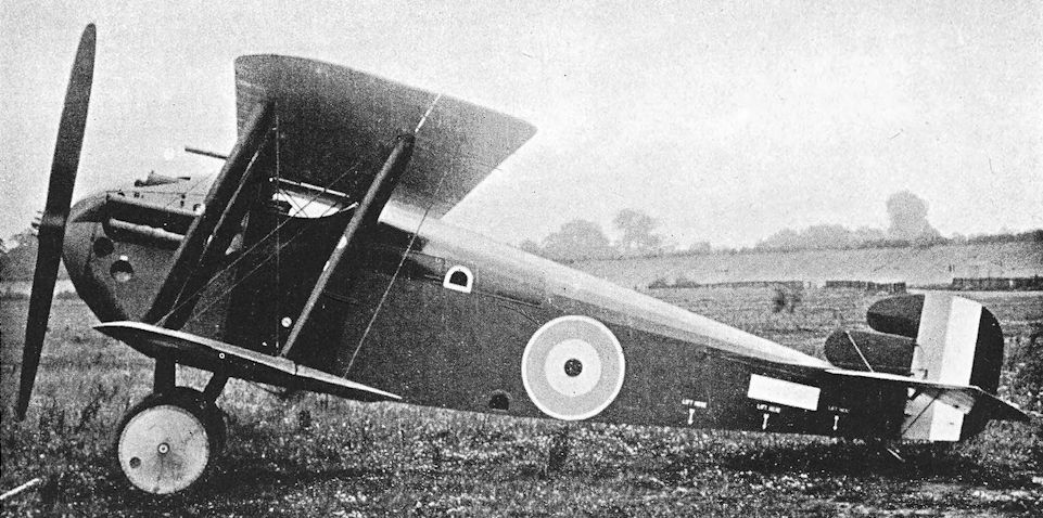
Sopwith Dolphin. Another view of the modified prototype which shows the new tail-unit with horn-balanced rudder.
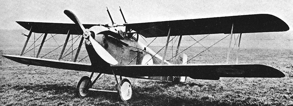
Three-quarter Front View of the Sopwith "Dolphin" (200 h.p. Hispano-Suiza engine).
Production Dolphin with side radiators, shallower top-decking and full armament.
Production Dolphin with side radiators, shallower top-decking and full armament.
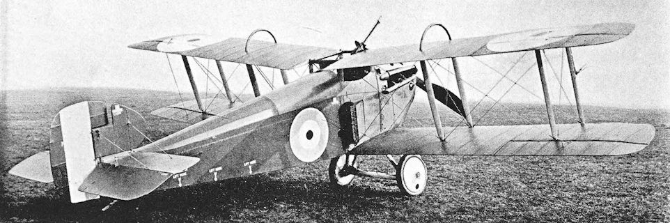
The prototype Dolphin night fighter at Brooklands on 19 February 1918; note the rollover crash pylons on the upper wing and the single flexible Lewis gun on the cabane structure.
Although this night lighter Dolphin (C3858) has protective half-hoops of steel above the wings and appears to be armed with a single Lewis gun only, provision for the Vickers guns is denoted by the case and link chutes behind the engine. Maker's caption: 'S.189 - Sopwith Dolphin Night Flyer - Type 5.F.1 - Feb, 1918'.
Although this night lighter Dolphin (C3858) has protective half-hoops of steel above the wings and appears to be armed with a single Lewis gun only, provision for the Vickers guns is denoted by the case and link chutes behind the engine. Maker's caption: 'S.189 - Sopwith Dolphin Night Flyer - Type 5.F.1 - Feb, 1918'.
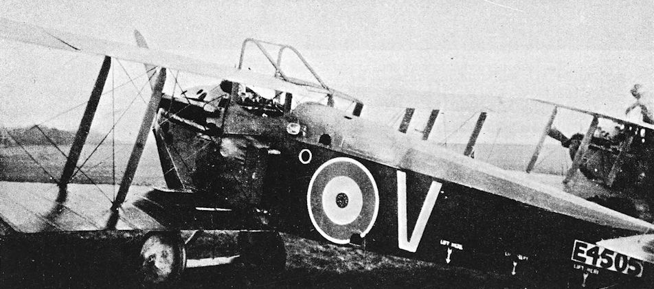
Dolphin of the training unit at Hooton Park, with crash pylons above centre-section and direct-drive Hispano-Suiza engine.
Sopwith 3.F.2 Hippo
CONTEMPORARY with the Rhino was another Sopwith two-seater named the Hippo which, as its type number 3.F.2 implied, was designed as a two-seat fighter. Like the Bulldog, the Hippo was powered by the 200 h.p. Clerget 11EB eleven-cylinder rotary engine.
In the Hippo, the measures taken to ensure the best possible fighting view for both pilot and observer were as drastic as those taken in the design of the Dolphin. The mainplanes were staggered backwards heavily, and the deep fuselage completely filled the gap between them. The pilot sat immediately in front of the leading edge of the upper wing, from which position he probably had a better all-round view than was afforded by any contemporary two-seat fighter. He was provided with two fixed Vickers guns.
The observer’s cockpit was situated immediately behind the rear spar of the upper centre-section. He had an excellent field of fire for his Lewis gun, but was separated from his pilot by a considerable distance; this latter factor would have been a disadvantage in combat.
The first Hippo had a small rectangular fin and the usual horn-balanced rudder. The ailerons were horn-balanced, but the balance areas were inset within the contours of the wing-tips. Once again the curious reluctance to fit a Scarff ring for the observer’s Lewis gun was in evidence, for there was only a rocking-post in the rear cockpit.
The second Hippo, X.11, differed from the first in several respects. An enlarged fin was fitted; it blended with the shape of the rudder to form a vertical surface similar in outline to the fin and rudder of the Camel. The second Hippo had plain ailerons of greater span than those of the first machine, and the mainplanes were rigged with a greater dihedral angle. A Scarff ring-mounting was fitted on the observer’s cockpit, and the top-decking of the fuselage was not so deep as on the first Hippo.
Official trials of the type were carried out in January and February of 1918. The Hippo was not, however, adopted for Service use, doubtless because its performance was inferior to that of the Bristol Fighter, which was then in service in hundreds.
SPECIFICATION
Manufacturers: The Sopwith Aviation Company, Ltd., Canbury Park Road, Kingston-on-Thames.
Power: 200 h.p. Clerget 11B.
Dimensions: Span: 38 ft 9 in. Length: 24 ft 6 in. Height: 9 ft 4 in. Chord: 5 ft. Gap: 4 ft 6 in. Stagger (negative): 1 ft 9 3/8 in. Dihedral: first machine, 3°; second machine, 5°. Incidence: 2°. Span of tail: 11 ft 3 in. Wheel track: 5 ft. Tyres: 700 X 100 mm. Airscrew diameter: 9 ft.
Areas: Wings: 340 sq ft. Ailerons: total 54-4 sq ft. Tailplane: 22-5 sq ft. Elevators: 18 sq ft. Fin: 4-6 sq ft. Rudder: 9 sq ft.
Weights and Performance: No. of Trial Report: M.170A. Date of Trial Report: February, 1918. Type of airscrew used on trial: Lang 4030. Weight empty: 1,481 lb. Military load: 363 lb. Crew: 360 lb. Fuel and oil: 386 lb. Loaded: 2,590 lb. Maximum speed at 10,000 ft: 115-5 m.p.h.; at 13,000 ft: 106-5 m.p.h.; at 15,000 ft: 101 m.p.h. Climb to 1,000 ft: 1 min; to 2,000 ft: 2 min; to 5,000 ft: 5 min 25 sec; to 8,000 ft: 9 min 45 sec; to 10,000 ft: 13 min 25 sec; to 12,000 ft: 18 min; to 15,000 ft: 28 min 35 sec; to 16,000 ft: 34 min 25 sec. Service ceiling: 17,000 ft.
Tankage: Petrol: main (pressure) tank 29 1/2 gallons; gravity tank 11 gallons; total 40 1/2 gallons. Oil: 9 gallons.
Armament: Two fixed, forward-firing Vickers machine-guns almost wholly enclosed within the fuselage above and behind the engine, and synchronised to fire through the airscrew. A single Lewis machine-gun or a pair of double-yoked Lewis guns were provided for the observer: the first Hippo had a single rocking-post mounting for the rear gun; in the second machine a Scarff ring-mounting was fitted.
Serial Numbers: X.11 : second machine, built under Licence No. 16.

Sopwith Hippo. The first Hippo with original small fin and rudder, horn-balanced ailerons, rocking-post mounting for rear gun, and shallow dihedral.

The second Sopwith 3F.1 Hippo, X11 at Brooklands with increased wing dihedral, smooth contoured fin and rudder, Scarff ring on rear cockpit and rear fuselage of reduced depth.
Sopwith 2.B.2 Rhino
THE second Sopwith design for a day-bomber was an unprepossessing two-seat triplane known as the Rhino. It was designed and built in 1917, and was powered by a 230 h.p. B.H.P. engine.
The Rhino was not a thing of beauty. The bomb-load was carried internally under the pilot’s cockpit, an arrangement which resulted in an ugly fuselage of great depth. The aircraft was of considerable historical significance, however, for it was probably the first military aeroplane to use an armament “pack”. The bombs were carried in a kind of crate, complete with release gear, which could be hoisted into the fuselage by tackle attached to the spars of the middle mainplane within the pilot’s cockpit. The object of this arrangement was to speed up the operation of attaching fresh bombs to the machine after a raid.
The equal-span wings had only a single bracing bay. The top centre-section was of extraordinarily wide span (10 feet 10 inches), and overhung the outwards-raked centre-section struts considerably. There were cut-outs between the spars of the centre-section of the middle wing: these were intended to improve downward view for the pilot, who sat in line with the central wing. Ailerons were fitted to all three wings, and these surfaces were originally horn-balanced. A faired rod linked the bottom and middle ailerons on each side, for the control lead was taken to the middle aileron. Middle and upper ailerons were connected by a cable. The tail assembly was generally similar to that of the Bulldog, but the almost absurdly small undercarriage vees were reminiscent of the Dolphin. A radiator block was mounted on each side of the fuselage below the engine, and the cooling area was regulated by means of frontal flaps similar to those of the production Dolphin.
The Rhino later appeared with plain ailerons and slightly rounded wing-tips. In its final form it had a Scarff ring-mounting for the observer in place of the rocking pillar-mounting which had been fitted to the earlier versions.
The Rhino was officially tested in February and March, 1918. Performance was not particularly good: in 1918 its Service ceiling of only 12,000 feet when fully loaded would have made it a very vulnerable machine, and its speed was not high. It was not adopted as a Service type.
SPECIFICATION
Manufacturers: The Sopwith Aviation Company, Ltd., Canbury Park Road, Kingston-on-Thames.
Power: 230 h.p. B.H.P.
Dimensions: Span: 33 ft. Length: 27 ft 8 in. Height: 10 ft 11 in. Chord: 6 ft. Gap: each 4 ft. Stagger: each 5 in.; total 10 in. Dihedral: 2 30'. Incidence: 3. Span of tail: 12 ft.
Weights (lb) and Performance:
Flight condition With bomb-load With bomb-load Without bombs
No. of Trial Report M.167A M.167B M.167A
Date of Trial Report February, 1918 March, 1918 February, 1918
Type of airscrew used on trial D.G.B.2627 A.M.2627 Lang 4020
Weight empty 2,185 2,184 2,185
Military load 538 606 51
Crew 360 360 360
Fuel and oil 507 440 465
Weight loaded 3,590 3,590 3,061
Maximum speed (m.p.h.) at
10,000 ft 103 103 -
m. s. m. s. m. s.
Climb to
6,500 ft 12 30 12 30 10 00
10,000 ft 24 50 24 50 18 35
Service ceiling (feet) 12,000 12,000 14,500
Endurance (hours) - 3 3/4 -
Areas: Wings: 545 sq ft. Ailerons: total 52 sq ft. Tailplane: 35-5 sq ft. Elevators: 18-5 sq ft. Fin: 5-5 sq ft. Rudder: 9 sq ft.
Tankage: Petrol: main tank 40 gallons, auxiliary tank 20 gallons; total 60 gallons. Oil: 7 1/2 gallons.
Armament: One fixed, forward-firing Vickers machine-gun mounted centrally above the engine, and synchronised to fire forward through the airscrew; one Lewis machine-gun on rocking-post mounting, later on Scarff ring-mounting, in rear cockpit. The bomb-load consisted of either four 112-lb, nine 50-lb, or twenty 20-lb bombs, contained in a “bomb pack” which was hoisted into the fuselage under the pilot’s cockpit.
Serial Number: X.8, built under Licence No. 14.
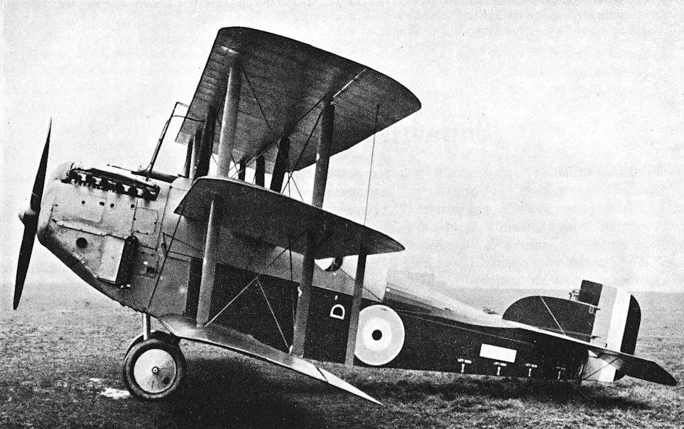
The Rhino with plain ailerons.
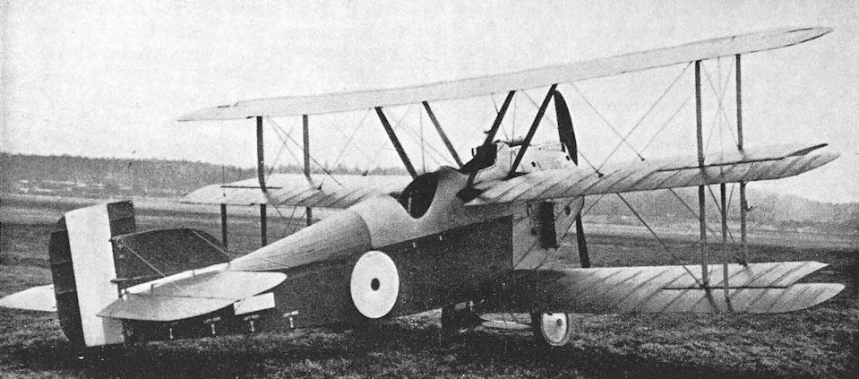
The inelegant Sopwith Rhino triplane prototype with original horn-balanced ailerons. Designed as a day bomber and powered by a 230 hp B.H.P. engine, horn-balanced ailerons were fitted to all three wings. Later prototypes featured rounded wingtips, eliminating the aileron horn balances. The Rhino had an internal bomb bay, which made the fuselage deeper than its contemporaries. Speed and ceiling were low and the aircraft was not produced in quantity and did not see service. Like many British designs, all the wings were essentially identical to facilitate mass production despite the fact that the top wing of biplanes and multiplanes generated more lift and thus should be larger.
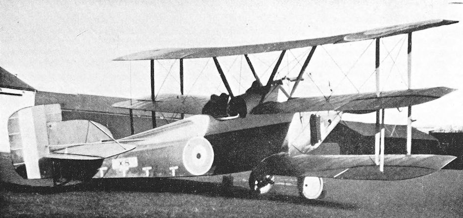
Rhino with modified rear cockpit and Scarff ring-mounting for observer’s gun. The serial number is X.8.
Sopwith A.T. and Sparrow
PROFESSOR A. M. LOW had begun to experiment with radio-controlled aeroplanes in 1916, with a view to producing a flying bomb. The experiments were necessarily somewhat lengthy, several aeroplanes were used in the course of the trials, and as a disguise for the true purpose of the experiments the aircraft concerned were referred to as Aerial Targets, usually abbreviated to A.T.
The Sopwith company designed and built two small biplanes to meet the requirements of the trials. The first was never completed. It was a single-bay biplane of extremely simple construction. The fuselage was a simple structure of square cross-section, and a four-wheel main undercarriage was to have been fitted. The wings were wire-braced wooden structures with widely-spaced ribs; there were no riblets. The upper mainplane was made in two halves which met at a central trestle-type cabane. If any form of lateral control was envisaged it must have been by wing-warping, but it seems more probable that reliance was placed on the appreciable dihedral angle to preserve lateral stability. Aerials for the wireless apparatus were wound round the overhanging portions of the upper mainplanes and round the rear portion of the fuselage. As the illustration shows, the original Sopwith A.T. sustained damage before completion: it was then abandoned.
This machine was followed by a larger biplane which was obviously a direct descendant of the Sopwith SL.T.B.P.: the new aircraft was named Sparrow. It was an equal-span, single-bay biplane powered by a 35 h.p. A.B.C. Gnat horizontally-opposed two-cylinder engine. Lateral control was by wing-warping, and the tail surfaces resembled (but were not identical to) those of the Pup. There was a cockpit situated between the rear interplane struts.
The structure of the Sparrow was simplified as much as possible, but it was a much less primitive aircraft than the original A.T. A reasonable amount of care was taken to reduce drag, for the engine was cleanly cowled and the cowling faired into the lines of the fuselage.
The experiments in radio control were successful, but did not reach the stage where a true flying bomb was built and used operationally. The Sparrow design therefore remained undeveloped.
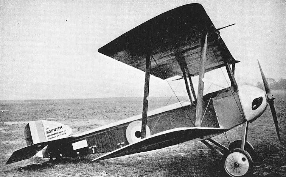
Sopwith Sparrow.
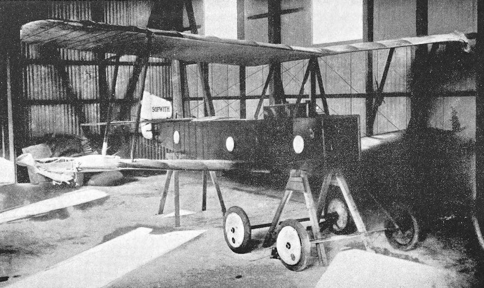
Sopwith A.T.
Sopwith Buffalo
IN the trench warfare which characterised the 1914-18 war, it became necessary for reconnaissance aircraft to fly low in order to establish the position of the infantry by close visual observation. This duty was known as Contact Patrol, and was inevitably dangerous: casualties among the pilots and observers were heavy.
In September, 1918, the Sopwith company produced an armoured two-seater specifically for contact patrol work. This machine was named Buffalo. It was a two-bay biplane powered by the 230 h.p. B.R.2 rotary engine, and was quite a handsome aircraft. The pilot sat fairly high up with his head in a large cut-out in the upper centre-section, and the observer was close behind him.
As on the Salamander, the entire forward portion of the fuselage was constructed of armour-plate which, on the first Buffalo, terminated at the back of the observer’s cockpit. This first machine, H.5892, originally had only a rocking-post mounting for the observer’s Lewis gun, but a Scarff ring-mounting was later fitted.
The second Buffalo, H.5893, had the armour-plate extended one bay farther aft. A slightly larger fin was fitted, and the rudder was different in outline from that of the first machine. The shape of the fairings behind the engine cowling was also modified.
Had the war lasted a few months longer, the Buffalo would have been in service in numbers, for it was about to go into production when the Armistice was signed. The first prototype, H. 5892, went to France on October 20th, 1918, when it was flown to No. 1 Aeroplane Supply Depot at Marquise. Doubtless it was intended to carry out Service trials under operational conditions, but the Armistice prevented the use of the Buffalo in action.
SPECIFICATION
Manufacturers: The Sopwith Aviation Company, Ltd., Canbury Park Road, Kingston-on-Thames.
Power: 230 h.p. Bentley B.R.2.
Dimensions: Span: 34 ft 6 in. Length: 23 ft 3 1/2 in. Height: 9 ft 6 in. Chord: 5 ft 6 in. Gap: 4 ft 6 in. Stagger: 1 ft 9 in. Dihedral: 2° 30'. Incidence: 1° 50'.
Areas: Wings: 326 sq ft. Ailerons: each 11 sq ft, total 44 sq ft. Tailplane: 23 sq ft. Elevators: 15-8 sq ft. Fin: 4 sq ft. Rudder: 9 sq ft.
Weights and Performance: No. of Trial Report: M.252. Date of Trial Report: February, 1919. Type of airscrew used on trial: L.5390. Weight empty: 2,178 lb. Military load: 158 lb. Crew: 360 lb. Fuel and oil: 375 lb. Loaded: 3,071 lb. Maximum speed at 1,000 ft: 114 m.p.h.; at 6,500 ft: 105-5 m.p.h. Climb to 3,000 ft: 4 min 55 sec; to 5,000 ft: 9 min 30 sec; to 6,500 ft: 16 min 55 sec. Service ceiling: 9,000 ft.
Tankage: Petrol: 25 gallons.
Armament: One fixed, forward-firing Vickers machine-gun on top of fuselage to port of centre, synchronised to fire through the airscrew; one Lewis machine-gun on Scarff ring-mounting on rear cockpit.
Serial Numbers: H.5892, H.5893.

Sopwith Buffalo. The first Buffalo, H.5892, with rocking-post gun-mounting in rear cockpit.

The second Buffalo, H.5893, with Scarff ring, modified engine fairings, extended armour-plate, and modified fin and rudder.
Sopwith 2.F.R.2 Bulldog
THE design of the Sopwith Bulldog was begun in 1917. It was a two-seat fighter-reconnaissance biplane, and was probably designed with a view to providing a replacement for the Bristol Fighter. Its development ran along lines somewhat similar to that of the Snipe.
Like the Snipe, the Bulldog first appeared as a single-bay biplane, and looked remarkably small for a two-seater. Structurally, the centre-section resembled that of the first prototype Snipe; but the pilot of the Bulldog sat, Dolphin-fashion, with his head in the large central aperture, and had an excellent upwards view. He had two Vickers guns mounted in a Snipe-like hump. The observer, some few feet farther aft, occupied a long cockpit and had two separate Lewis guns. His forward gun was carried on a telescopic pillar-type mounting. As the mounting was extended it automatically raised a small flap hinged to the rear spar of the centre-section; this flap then acted as a windshield for the observer. The second Lewis gun was mounted on a swinging pillar-type mounting.
The Bulldog was powered by the big eleven-cylinder Clerget 11EB rotary engine, nominally of 200 h.p. The usual bulbous fairings were fitted behind the cowling. The tail-unit was generally similar to that of the second and third Snipe prototypes: a relatively large rudder had a horn-balance area which swung above a low fin. The undercarriage was a simple vee structure, typical of Sopwith design.
The second version of the Bulldog retained the same engine, fuselage and tail-unit, but was fitted with two-bay wings of increased span and area. When it first appeared it had large horn balances on the ailerons of both upper and lower wings. These were later abandoned, and the Bulldog was fitted with new wings which had plain ailerons.
The Clerget-powered machine was designated Sopwith Bulldog Mark I. Performance was not particularly good; but a third version, the Bulldog Mark II, was fitted with the 360 h.p. A.B.C. Dragonfly la radial engine, and doubtless would have performed well but for the erratic behaviour of its power-unit.
The aircraft itself had the two-bay wings with plain ailerons. It was used more or less as a flying test-bed for the Dragonfly engine: as the illustration shows, all armament was removed, and the rear cockpit had a very close coaming about it. Official tests of the Bulldog II began in June, 1918, at Farnborough.
Neither version of the type was adopted for Service use.
SPECIFICATION
Manufacturers: The Sopwith Aviation Company, Ltd., Canbury Park Road, Kingston-on-Thames.
Power: Bulldog Mk. 1: 200 h.p. Clerget 11EB. Bulldog Mk. II: 360 h.p. A.B.C. Dragonfly la.
Dimensions (two-bay version): Span: 33 ft 9 in. Length (Mk. I): 23 ft. Height: 8 ft 9 in. Chord: 5 ft 6 in. Gap: 4 ft 6 in. Stagger: 1 ft 3 in. Dihedral: 3°. Incidence: 2°. Span of tail: 11 ft.
Areas (two-bay version): Wings: 335 sq ft. Ailerons: total 49-2 sq ft. Tailplane: 22-75 sq ft. Fin: 3-5 sq ft. Rudder: 9 sq ft.
Weights (lb) and Performance:
Version Mk. I, two-bay wings, plain ailerons Mk. II
No. of Trial Report M.197 -
Date of Trial Report May, 1918 July, 1918
Type of airscrew used on trial Lang 4030 -
Weight empty 1,441 -
Military load 318 321
Crew 360 360
Fuel and oil 376 510
Weight loaded 2,495
Maximum speed (m.p.h.) at
10,000 ft 109 -
m. s. m.s.
Climb to
2,000 ft - - 1 37
3,200 ft - - 2 50
4,000 ft - - 3 40
5,000 ft - - 4 32
6,000 ft - - 5 27
6,500 ft 8 25 - -
8,000 ft - - 7 20
9,000 ft - - 8 23
10,000 ft 15 35 9 28
I 1,000 ft - - 10 35
12,500 ft - - 12 46
14,000 ft - - 14 50
15,000 ft 38 55 16 28
Service ceiling (feet) 15,000 -
Endurance (hours) 2 -
Tankage: Petrol: 61 gallons. Oil: 6 1/2 gallons.
Armament: Two fixed, forward-firing Vickers machine-guns, synchronised to fire through the airscrew, for which
1,200 rounds of ammunition were provided; two Lewis machine-guns in rear cockpit, the forward one on a central telescopic pillar mounting, the other on a swinging pillar-mounting.
Serial Numbers: X.3: Mk. I, two-bay. X.4: Mk. II.

The first Sopwith Bulldog with Clerget engine and single-bay wings.
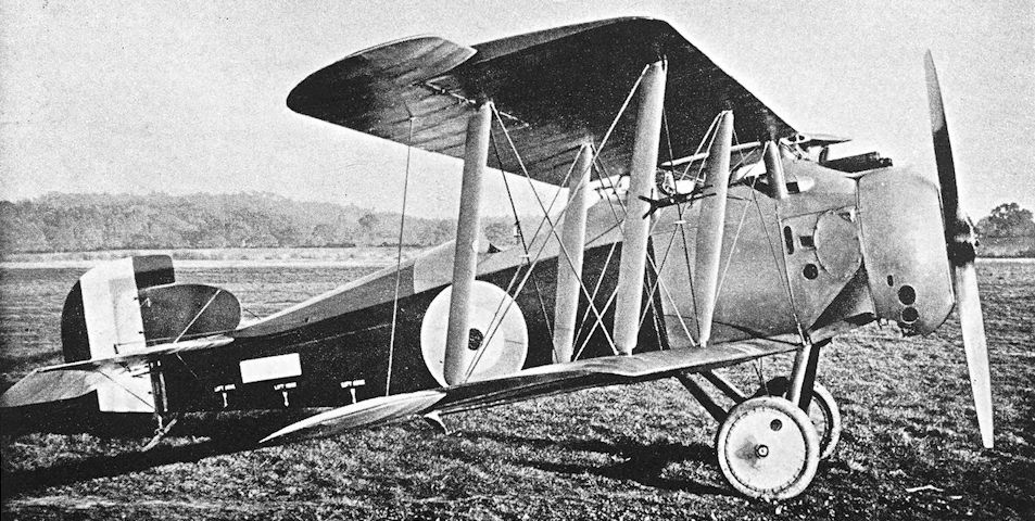
The second Sopwith Bulldog, as yet unmarked as X3, at Brooklands with two-bay wings and horn-balanced ailerons.
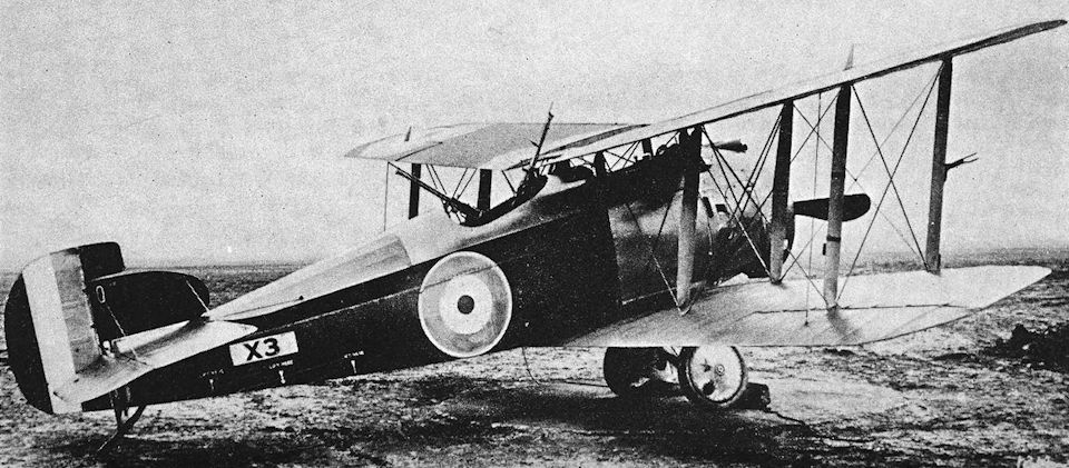
The first (second ???) Bulldog as tested at Martlesham Heath numbered X3 and with plain ailerons.
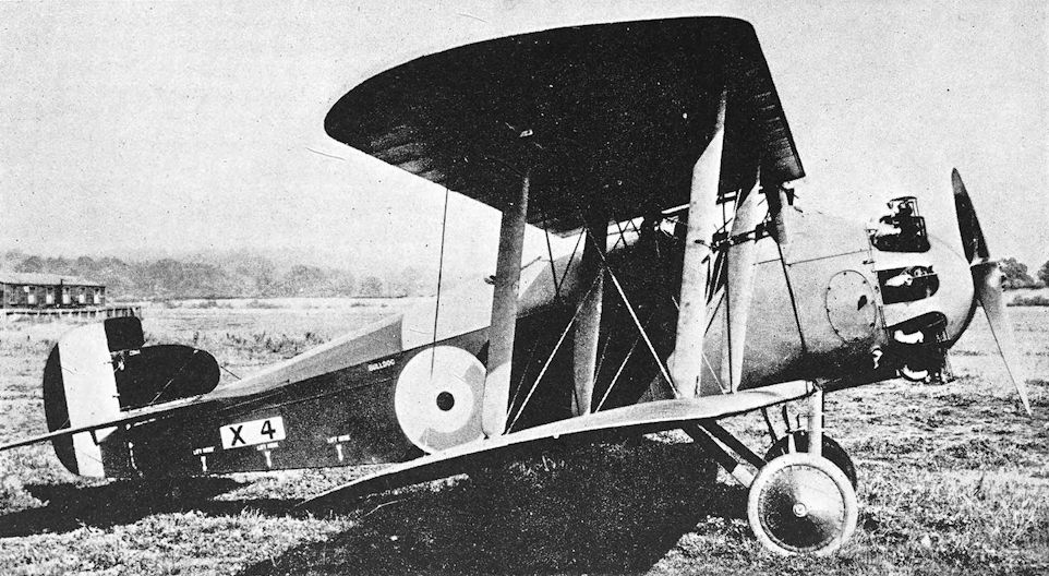
Sopwith Bulldog Mk. II with Dragonfly engine and close coaming about rear cockpit.
Sopwith Dragon
THE experimental installation of a 320 h.p. A.B.C. Dragonfly I engine in the Snipe prototype B.9967 in April, 1918, had proved so successful that the Snipe design was modified for production with the radial engine, doubtless as an insurance against any failure of the Nieuport Nighthawk. The revised design was renamed Dragon, and the more powerful Dragonfly Mark IA engine of 360 h.p. was adopted as the standard power-unit.
The prototype Dragon was the modified Snipe airframe E.7990, and was flying in January, 1919. At that time it had plain ailerons, and its fin and rudder were identical to those ultimately fitted to production Snipes. Despite the fact that the Armistice was past, production of the Dragon continued into the summer of 1919. Production machines had horn-balanced ailerons on the upper wings, and at least one Dragon had a modified exhaust system which incorporated exhaust-heated muffs for the induction system.
The Dragon J.3628 went to America for test purposes, and was flown at Wright Field.
The type did not survive. The Dragonfly engine was unsuccessful, and the Dragon shared the fate of those of its contemporaries which had the same power-unit.
SPECIFICATION
Manufacturers: The Sopwith Aviation Company, Ltd., Canbury Park Road, Kingston-on-Thames.
Power: 360 h.p. A.B.C. Dragonfly IA.
Dimensions: Span: upper 31 ft 1 in., lower 30 ft. Length: 21 ft 9 in. Height: 9 ft 6 in. Chord: 5 ft. Span of tail: 9 ft 2 in.
Areas: Wings: 271 sq ft. Ailerons: each upper 12-5 sq ft, each lower 10 sq ft, total 45 sq ft. Tailplane: 15 sq ft. Elevators: 11-2 sq ft. Fin: 2-75 sq ft. Rudder: 9 sq ft.
Weights: Loaded: 2,132 lb.
Performance: Maximum speed: 150 m.p.h. Climb to 10,000 ft: 7 min 30 sec. Service ceiling: 25,000 ft.
Armament: Two fixed, forward-firing Vickers machine-guns mounted on top of fuselage above and behind the engine, synchronised to fire through the airscrew.
Serial Numbers: E.7990: prototype, converted from Snipe. Production machines were numbered between and about J.3628 and J.3704.

A production Sopwith Dragon, said to be J3909, with horn-balanced upper ailerons and heating muffs round the exhaust pipes.

Although its number is obscured, this aeroplane is E7990, with its new production-type tail. The Sopwith picture is captioned: 'S.731 - Sopwith Dragon. - 360 hp A.B.C. Engine Experimental No.2 - Jan. 1919'.

Production Dragon with horn-balanced ailerons.
Sopwith T.F.2 Salamander
THE experiments with the Sopwith T.F.1 version of the Camel had successfully proved the feasibility of building an armoured single-seater for ground-attack work. The nature of the trench warfare of the period demanded ground-attack aircraft which would provide a relatively accurate yet flexible means of bringing machine-guns to bear on ground targets in the face of heavy defensive fire. The Sopwith aeroplane which was passed out by the Sopwith experimental department on April 26th, 1918, promised to perform that hazardous duty efficiently.
The new machine was the T.F.2 Salamander, an equal-span two-bay biplane which was clearly developed from the Snipe. The same engine, the B.R.2, was employed; and in general appearance the two aircraft were similar. The Salamander could be most easily distinguished by its flat-sided fuselage, the longer front legs of the undercarriage vees, and the head-rest behind the cockpit.
The entire forward portion of the fuselage was constructed of armour-plate which weighed no less than 650 lb, and formed an armoured container for the pilot and fuel tanks. To this box-like structure the longerons were attached. There were fairings on either side behind the circular engine cowling, and a rounded top-decking was fitted.
The prototype Salamanders had plain ailerons of the same length as those of the two-bay Snipe, and a similar vertical tail-assembly was fitted. The first prototype, E.5429, had single control horns on the ailerons, but E.5431 had two control horns on each aileron and two cables connecting upper and lower surfaces. In May, 1918, E.5429 was sent to France for Service trials, and it was not long before the Salamander was ordered into production.
The production Salamanders had ailerons of longer span than those of the prototypes; whilst the fin and rudder were increased in area and so modified in outline that they resembled those fitted to production Snipes. Plain ailerons and the small fin were fitted to the early production Salamanders, but when horn-balanced upper ailerons were introduced for the Snipe the corresponding surfaces of the Salamander were similarly modified, and the larger fin was also fitted.
The standard armament consisted of two fixed Vickers machine-guns firing forward through the airscrew: two thousand rounds of ammunition were carried. Experimental multiple-gun installations were made: one Salamander was fitted with a battery of eight guns, all of which fired downwards through the floor of the fuselage.
Salamander production was gaining momentum when the Armistice was signed, but only a few machines had reached France by that time. The majority of the machines in existence had not progressed beyond the Aircraft Acceptance Park. Production was continued into the summer of 1919, but the Salamander found no place in the peace-time R.A.F.
SPECIFICATION
Manufacturers: The Sopwith Aviation Company, Ltd., Canbury Park Road, Kingston-on-Thames.
Power: 230 h.p. Bentley B.R.2.
Dimensions: Span: prototype, 30 ft 1 1/2 in.; production, upper 31 ft 2 5/8 in., lower 30 ft 1 1/2 in. Length: prototype, 18 ft 9 in.; production, 19 ft 6 in. Height: 9 ft 4 in. Chord: 5 ft. Gap: 4 ft 3 in. Stagger: 1 ft 5 in. Dihedral: 4°. Incidence: 1° 50'. Span of tail: 9 ft 2 in.
Areas: Wings: prototype, 266-5 sq ft; production, 272 sq ft. Ailerons: prototype, each 10 sq ft; total 40 sq ft. Production, each upper 14 sq ft; each lower 11-5 sq ft; total 51 sq ft. Tailplane: 15 sq ft. Elevators: 11 sq ft. Fin (production): 2-75 sq ft. Rudder (production): 9 sq ft.
Weights and Performance: No. of Trial Report: M.211. Date of Trial Report: June, 1918. Type of airscrew used on trial: Lang 5300. Weight empty: 1,844 lb. Military load: 230 lb. Pilot: 180 lb. Fuel and oil: 258 lb. Total: 2,512 lb. Maximum speed at 500 ft: 125 m.p.h.; at 6,500 ft: 123-5 m.p.h.; at 10,000 ft: 117 m.p.h. Climb to 6,500 ft: 9 min 5 sec; to 10,000 ft: 17 min 5 sec. Service ceiling: 13,000 ft. Endurance: 1 1/2 hours.
Tankage: Petrol: 29 gallons.
Armament: Two fixed, forward-firing Vickers machine-guns mounted above and behind the engine, synchronised to fire through the airscrew; 2,000 rounds of ammunition were carried for these guns. Experimental installations of multiple machine-guns were made.
Production and Allocation: On October 31st, 1918, the R.A.F. had thirty-seven Salamanders on charge. Of these, only two were in France. In the United Kingdom, one was at an experimental station; one was with a squadron mobilising; one at another Home Establishment unit; one in store; and thirty-one were at Aircraft Acceptance Parks or with contractors. During 1918 a total of three had been sent to France and two to training units.
Serial Numbers: E.5429-E.5434: prototypes built by Sopwith. Production Salamanders were numbered between and about F.6526 and F.6602.
Costs:
Airframe without engine, instruments and guns £1,138
B.R.2 engine £880
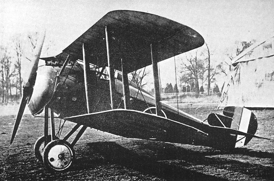
Early production Salamander with enlarged rudder.
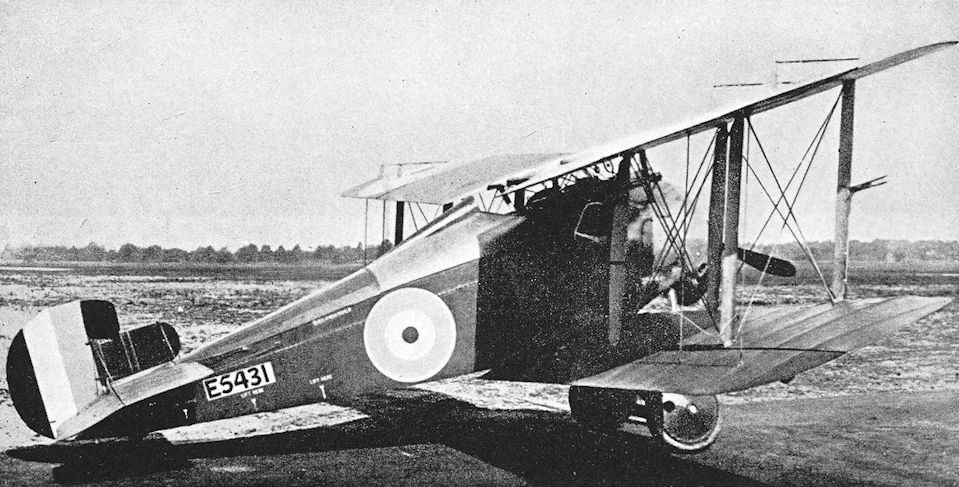
Sopwith Salamander. The third prototype Salamander
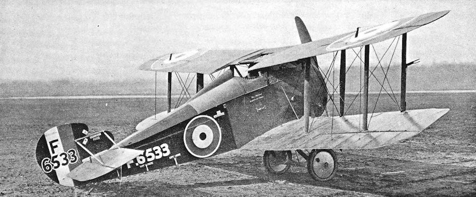
This production Salamander was sent to America, and is here seen at McCook Field. The small lettering beside the cockpit states: “This machine is not to be flown.”
Sopwith Scooter and Swallow
THAT there was nothing stereotyped in Sopwith design-thinking has been amply demonstrated in the preceding descriptions of earlier Sopwith types, but none had been a monoplane. The first Sopwith monoplane was the Scooter, which appeared in June, 1918. It was in fact originally known as the Sopwith Monoplane No.1.
The Scooter consisted of an F.1 Camel fuselage fitted with a parasol wing which was mounted very close to the fuselage and was braced by Rafwires. A tall pyramidal cabane was mounted above the centre portion of the wing, and four landing wires ran from it to each half of the mainplane. Flying wires ran from the bottom longerons to the mainplanes at favourable angles. The main flying wires were duplicated.
The Scooter provided Hawker with a fine aerobatic mount, and survived the Armistice to go on the Civil Register, first as K.135 and later as G-EACZ. It was still flying in 1925.
From the Scooter was developed the Swallow, a single-seat fighter originally designated Sopwith Monoplane No. 2. Again a Camel fuselage (that of B.9276) was used, but the armament was retained and the engine was the 110 h.p. Le Rhone in place of the 130 h.p. Clerget which was fitted to the Scooter. The Le Rhone, although of lower nominal output than the 130 h.p. Clerget, could, when properly tuned, deliver rather more power: it gave 128-137 h.p., whereas the Clerget delivered 125 h.p. The Swallow appeared in October, 1918.
The Swallow’s wing was of slightly greater span and area, and was rather higher above the fuselage to give the pilot access to his guns, which were fully exposed and not partially covered by a hump, as on the Camel. The centre-section struts were longer than those of the Scooter and had a more pronounced outwards rake when seen from the front. The central portion of the wing was reinforced, and the ailerons were of longer span than those of the Scooter.
The Swallow arrived too late to be developed for Service use. The official trials conducted in May, 1919, showed no improvement in performance over the Camel.
SPECIFICATION
Manufacturers; The Sopwith Aviation Company, Ltd., Canbury Park Road, Kingston-on-Thames.
Power: Scooter: 130 h.p. Clerget. Swallow: 110 h.p. Le Rhone.
Areas: Wings: Swallow, 162-5 sq ft.
Weights and Performance: No. of Trial Report: M.255. Date of Trial Report: May, 1919. Type of airscrew used on trial: L.5430. Weight empty: 889 lb. Military load: 150 lb. Pilot: 180 lb. Fuel and oil: 201 lb. Loaded: 1,420 lb. Maximum speed at 10,000 ft: 113-5 m.p.h.; at 15,000 ft: 105 m.p.h. Climb to 6,500 ft: 5 min 35 sec; to 10,000 ft: 9 min 55 sec; to 15,000 ft: 20 min. Service ceiling: 18,500 ft.
Armament: Scooter: none. Swallow: two fixed, forward-firing Vickers machine-guns mounted on top of the fuselage, synchronised to fire through the airscrew.
Serial Numbers: Swallow: B.9276.

During its life of nearly ten years the Scooter was variously marked. This view was taken by Sopwith on the same occasion (July 1918) as the 3/4-rear aspect already shown. The reflection of the roundel seen on the wing is itself a reflection on the quality of finish.

The sole Sopwith Swallow, serial no B 9276, photographed in October 1918. Employing a standard Camel fuselage, whose serial it used, the parasol-mounted wings had already been flown and tested on the Sopwith Scooter. Armed with twin, synchronised Vickers guns, the 110hp Clerget-engined Swallow had a top level speed of 113.5mph at 10.000 feet, some 7.5mph slower than the company's Snipe that was already in large scale production.
Sopwith 8F. 1 Snail
NEXT after the Snipe in the line of Sopwith single-seat fighters was the 8F.1 which - oddly, in view of its designed function - was named Snail. It was one of the first aeroplanes to be named in accordance with the official system of nomenclature defined in T.D.I. 506, as amended by T.D.I. 506A*; and its name was, in one sense at least, apposite, because the basic design of the Snail employed a monocoque fuselage which could be likened to a snail’s shell.
* The initials T.D.I. signified Technical Department Instruction.
The fuselage of the Sopwith Snail was of circular cross-section, and consisted of a plywood skin applied to a structure of circular formers and wooden stringers. The lines of the fuselage were good, and the complete aircraft was of pleasing appearance. The single-bay wings had positive stagger, and the pilot sat in line with the trailing edge of the upper mainplane. Ailerons were fitted to upper and lower wings.
The monocoque Snail appeared in May, 1918, when its structure was regarded as unusual in Britain. This typically conservative attitude towards a breakaway from conventional British methods of fuselage construction was probably responsible for the existence of a second and quite different version of the design.
The second Snail was designated Snail Mark II in order to distinguish it from the monocoque Snail Mk. I. In point of time the Mk. II preceded the Mk. I, for it appeared in April, 1918. That fact may have been attributable to the simpler construction of its fuselage, which was a fabric-covered structure of conventional design. The basic wire-braced wooden-box girder was faired out to a rounded cross-section.
The difference between the two Snails was accentuated by the rigging of the wings of the Mk. II. The pilot was accommodated in a manner reminiscent of the Dolphin: he sat high up with his head in the central aperture of the centre-section. As on the Dolphin, the mainplanes had a slight backwards stagger.
Both Snails had the same wings and tail-unit. The fin and horn-balanced rudder were of similar form to those of the second Snipe prototype.
Neither version of the Snail was adopted for Service use. No doubt the waywardness of the A.B.C. Wasp engine contributed to the abandonment of the design.
SPECIFICATION
Manufacturers: The Sopwith Aviation Company, Ltd., Canbury Park Road, Kingston-on-Thames.
Power: 170 h.p. A.B.C. Wasp I.
Dimensions: Span: 25 ft 9 in. Length: 18 ft 9 in. Height: 8 ft 3 in.
Areas: Wings: 250 sq ft.
Weights: Loaded: 1,478 lb.
Performance: Maximum speed: 127 m.p.h. Climb to 10,000 ft: 7 min 58 sec.
Armament: Two fixed, forward-firing Vickers machine-guns, one either side of the cockpit, synchronised to fire through the airscrew.
Serial Numbers: C.4284-C.4289.

Snail C4284, immaculate without the test instrumentation shown in the foregoing view, though the Sopwith caption is dated 'April 13/18'.
The Mk.II version of the Sopwith Snail with stringer and fabric fuselage and negative stagger.
The Mk.II version of the Sopwith Snail with stringer and fabric fuselage and negative stagger.

Another single seat fighter design of late 1917 origin doomed by using the ultimately abandoned 170hp ABC Wasp was the Sopwith 8F1 Snail. Of the six Snails ordered only two were to be completed, the first, serial no C 4284, with its fabric-on-stringer fuselage differing considerably from the second aircraft, serial no C 4288, seen here, with its monocoque plywood fuselage and forward staggered wings. To be armed with twin forward-firing, fixed and synchronised Vickers Guns, the Snail's performance, even without the engine troubles, appears to have been little better than that of the Sopwith Camel, leading to the Snail's abandonment.
Sopwith Snark
IN the design of a single-seat fighter intended specifically for high altitude work, the Sopwith company returned in 1918 to the triplane layout which it had exploited so successfully in 1916. The new triplane was named the Snark, but differed markedly in construction and appearance from the delightful Clerget Triplane of 1916.
Profiting from the experience gained with the monocoque fuselage of the Snail C.4288, the Sopwith company gave the Snark a similar fuselage. The single-bay triplane wings had simple interplane struts and conventional cross-bracing, but the stagger of the top wing relative to the middle was less than that of the middle wing relative to the bottom. Ailerons were fitted to all wings. The engine was the 320 h.p. A.B.C. Dragonfly I, and later the 360 h.p. Dragonfly IA was used.
The first Snark, F.4068, had no spinner, but F.4070 appeared with a blunt spinner and a carefully cowled engine. The version with the Dragonfly IA was fitted with four Lewis guns in addition to the normal twin Vickers guns. These Lewises were mounted under the bottom wings, two on each side; like the outboard guns of No. 87 Squadron’s Dolphins they could not be reloaded in flight.
The Snark was credited with a good rate of climb, a high ceiling and excellent manoeuvrability, but it had a built-in liability in its Dragonfly engine. It was not adopted for Service use.
SPECIFICATION
Manufacturers: The Sopwith Aviation Company, Ltd., Canbury Park Road, Kingston-on-Thames.
Power: 360 h.p. A.B.C. Dragonfly IA.
Dimensions: Span: 26 ft 6 in. Length: 20 ft 9 in. Height: 10 ft 1 in.
Areas: Wings: 322 sq ft.
Weights: Loaded: 2,283
Performance: Maximum speed: 130 m.p.h.
Armament: Two fixed, forward-firing Vickers machine-guns synchronised to fire through the airscrew, supplemented by four Lewis machine-guns, two under each bottom mainplane.
Serial Numbers: F.4068-F.4070.

The third Snark, with spinner and improved engine cowling.
Sopwith 7F.1 Snipe
IN April, 1917, the Air Board ordered three experimental examples of a new type of rotary engine which had been designed by Lieutenant W. O. Bentley. This was the B.R.2, an enlarged development of the earlier 150 h.p. B.R.1 which had been used to good purpose as the power plant of many Sopwith Camels.
The first B.R.2 engine ran on the test bench early in October, 1917, and was an instant success. It delivered 234 h.p., and its behaviour was encouraging; it was heavier than the B.R.1 by only 93 lb, and was obviously well-suited for use in fighter aircraft. At a meeting of the Air Board, Major-General Brancker went so far as to say that the B.R.2 could be used in every type of aeroplane then in France, with the exception of bombers. At that meeting the Air Board discussed a production programme which provided for the manufacture of 1,500 Bentley rotaries each month, and by the middle of October orders already placed for the B.R.2 represented a monthly output of 900 engines.
With this powerful new engine at their disposal, it was only natural that the Air Board should seek a single-seat fighter powered by the B.R.2 as an ultimate replacement for the Sopwith Camel. It was equally natural that the Sopwith company should want to build an aeroplane to meet the official requirements.
A new design was drawn up under the type number 7F.1 and was named Snipe. The first machine bore a strong resemblance to the Camel, particularly in its fuselage and tail unit. There appeared to be no marked basic structural difference between the fuselage of the original Snipe and that of the Camel, but obviously the later aircraft had to be designed to accommodate the larger diameter and greater power of the B.R.2 engine. The airframe was completed before an example of the B.R.2 engine was available, however, and the Snipe was first flown with a 150 h.p. B.R.1 engine. The B.R.2 was substituted at a later stage. The sides of the first Snipe’s fuselage were flat, except for the usual fairings behind the circular engine cowling, and the top-decking was proportionately deeper than that of the Camel. The fin and rudder were indistinguishable from those of the Camel. The undercarriage was a simple vee structure of the type favoured by the Sopwith company.
The wings of the first Snipe were of equal span, and had single-bay bracing. Upper and lower wings had equal dihedral, which brought the upper centre-section down almost to the level of the pilot’s eyes; there was a large cut-out in the centre-section in order to improve the pilot’s view, and the trailing portions of the upper wing-roots were also cut away. The centre-section itself was unusually narrow for a Sopwith type, and was supported on four short struts which, in end elevation, were vertical. Ailerons were fitted to upper and lower wings.
The armament was identical to that of the F.1 Camel, both in nature and disposition: two Vickers guns were mounted above and behind the engine in a hump-like fairing. The hump was of better form than that of the Camel and enclosed rather more of the guns.
The second Snipe prototype followed closely on the first, and displayed several marked differences. The fuselage was given a better aerodynamic form by continuing the side fairings right back to the tail; the bottom remained quite flat throughout its length. The tail-unit was modified: a small rectangular fin with rounded leading edge was fitted, and a new, horn-balanced rudder replaced the original plain rudder.
Single-bay wings were retained on the second Snipe, but the structure was modified. A wider centresection was fitted, and the centre-section struts were lengthened and splayed outwards. The trailing portion of the centre-section was partly cut away to improve the pilot’s view; and a further small central aperture, roughly semi-circular in shape, was made forward of the rear spar.
The single-bay Snipe underwent official trials in December, 1917, and proved to have a good performance, particularly in rate of climb. It was considered that the single-bay wings were not sufficiently strong, however, and a third version of the design appeared in January, 1918, with two-bay wings; the wing span was increased by 4 feet 3 inches.
The third Snipe retained the small fin and horn-balanced rudder, and at one time was fitted with a Lewis gun in addition to the twin Vickers. The third weapon may have been a requirement of the original specification, for the Boulton & Paul Bobolink, one of the Snipe’s competitors, was originally designed to have a Lewis gun on the upper wing. So was the Armstrong Whitworth Armadillo, and the Austin A.F.T.3 and Nieuport B.N.1 were flown with a Lewis gun supplementing their twin Vickers guns. In the case of the Snipe, the Lewis was mounted above the centre-section and slightly to starboard.
The two-bay Snipe was officially tested in February, 1918. The new wing cellule created more drag than the original single-bay wings, and the performance suffered in consequence. In terms of speed the Snipe was no better than the Camel and inferior to the Dolphin, but its rate of climb was superior to both. Its handling characteristics were excellent but very different from those of the Camel. It was manoeuvrable, but not in the same hypersensitive manner as the Camel, and it did not display the viciousness that had made the earlier type so dangerous in inexperienced hands. The Snipe’s rudder underwent further slight modification. It was enlarged by increasing its height, and consequently the top of the horn balance area was slightly rounded. The fifth prototype, B.9966, had this form of rudder.
The Snipe was officially selected as the successor to the Camel. It was regarded as a better proposition, from the production standpoint, than such types as the Bobolink; and it probably gave its pilot a better all-round view. The production machine was officially styled Snipe Mark I. Production was undertaken on a large scale; more than 1,800 Snipes were ordered from six different contractors. First deliveries were made in the summer of 1918, and by the end of September 161 Snipes had been completed. The production machines generally resembled B.9966, but had an enlarged rectangular cut-out in the centre-section and a different rudder. The new rudder was of broader chord and had a slightly elongated horn balance with rounded leading edge. At the same time, the leading edge of the fin was made semicircular.
Experiments continued, with the aim of improving manoeuvrability. The fifth prototype B.9966 was fitted with horn-balanced ailerons on the upper wings and a new, enlarged tail-unit. A sharply tapered tailplane with broad root chord was fitted, and the elevators were horn-balanced and inversely tapered. The rudder was yet again enlarged and its balance area had a vertical leading edge. A completely new fin was fitted: it blended with the rudder to give the vertical tail an oval contour.
The horn-balanced ailerons and the revised fin and rudder were standardised, and later production Snipes were fitted with them. It is probable that many of the earlier machines were retrospectively modified.
Comparatively few Snipes reached the Western Front before the Armistice: by October 31st, 1918, only 97 were in France. More followed, but at the time of the Armistice only three squadrons were equipped with the type. No. 43 Squadron of the R.A.F. and No. 4 Squadron of the Australian Flying Corps were the first units to be equipped with the Snipe, and late in October, 1918, the Camels of No. 208 Squadron, R.A.F., were replaced by Snipes.
Although it saw little action during the war, the Snipe will always deserve an honoured place in history, as the machine on which Major W. G. Barker fought the action which earned him the award of the Victoria Cross. On October 27th, 1918, while he was attached to No. 201 Squadron on a refresher course, Barker was flying a Snipe some 21,000 feet above the Foret de Mormal. He attacked and shot down an enemy two-seater, but was then wounded in the right thigh by a Fokker D.VII which had attacked from below. Barker spun down and pulled out in the middle of an enemy formation about fifteen strong; he attacked two of them and they spun away. These two combats were inconclusive, but Barker put his Snipe on a third Fokker’s tail at about ten yards range and shot it down in flames. At that moment he was again wounded, this time in the left thigh. He fainted, and his Snipe fell out of control. When he regained consciousness he found himself in the midst of another formation of 12 to 15 enemy fighters. He shot one down in flames, but his left elbow was shattered by an enemy bullet. Again he fainted, and again found himself surrounded by enemy machines when he recovered, now down to 12,000 feet. Smoke was issuing from the Snipe and, under the impression that he was doomed, Barker tried to ram a Fokker D.VII which was just in front of him. At the last moment he opened fire at a range of only two to three yards, and the Fokker fell in flames. Barker dived away towards the Allied lines, but was challenged by another enemy formation, eight strong. He shook them off, crossed the lines a few feet above the ground, and crashed close to a British balloon. Seldom was a Victoria Cross more richly deserved; and the Snipe could hardly have won a more glorious testimonial of its fighting quality.
The Snipes participated in the work of harrying the retreating Germans, and the machines of No. 4 (Australian F.C.) Squadron distinguished themselves on October 30th, when they took part in the 80th Wing’s successful raid on the enemy aerodrome at Rebaix. On their return journey the Snipes attacked enemy transport and caused great havoc.
The Snipes were again in action on November 9th, when the 80th Wing hastened the enemy’s defeat with a devastating attack on Enghien.
It was official policy to re-equip all Sopwith Camel squadrons with Snipes from January, 1919, onwards. This policy applied also to Home Defence squadrons; late in 1918 a few Snipes had been tested to determine their suitability for night fighting and had proved to be completely satisfactory.
Of the 97 Snipes which had reached France by October 31st, 1918, two had been delivered to the Independent Force, presumably for the use of No. 45 Squadron. A long-range variant of the Snipe was built specially for the Independent Force to enable the fighter squadron to escort the bombers on long raids. This version had the Sopwith type number 7F.1a, and had a special fuel tank which was shaped to act as the pilot’s seat. The flight endurance of the 7F.1a Snipe was 4 1/2 hours. It was officially designated Snipe Mark IA, and was regarded as a stop-gap long-range fighter pending availability of the long-range version of the Martinsyde Buzzard.
It is not known whether the two Snipes which had reached the Independent Force by the end of October, 1918, were 7F.1a variants. The official test report on the type is dated November, 1918.
Official records show that two Snipes were with the Grand Fleet on October 31st, 1918, and there can be little doubt that the type was at least considered as a replacement for the Camels, Pups and Beardmore W.B.IIIs that were in use as ship-board fighters. With this in view, a Snipe was fitted with hydrovane gear to minimise the risk of overturning when ditching: this version underwent official trials in May, 1919.
For experimental purposes, a Snipe was fitted with a large blunt spinner; and the sixth prototype, B.9967, was powered by the 320 h.p. A.B.C. Dragonfly radial engine. It was one of the first aeroplanes to be fitted with the Dragonfly, and was extensively used to test the new engine. This latter Snipe had plain ailerons, and its tail-unit was identical to that originally used on B.9966. It was flying as early as April, 1918, and achieved the remarkable speed of 156 m.p.h. It was later developed into a new Sopwith type with the name of Dragon.
The Armistice was signed before the Snipe could get into its operational stride, but there was fairly general agreement that it was the best Allied single-seater in use at the end of the war. Although not so fast as the Fokker D.VII, its ability to turn more tightly made it a better machine for the dog-fights which were so typical of its day.
The Snipe was adopted as the R.A.F.’s standard fighter immediately after the war, and saw service at home and overseas for many years. A number were converted into two-seaters for instructional purposes, and the type did not disappear from the Service until 1927. It was a favourite aerobatic mount, and gave displays at several of the R. A.F. pageants at Hendon, flown by pilots whose names in the official programme were followed by the number of enemy aircraft they had shot down during the war.
SPECIFICATION
Manufacturers: The Sopwith Aviation Company, Ltd., Canbury Park Road, Kingston-on-Thames.
Other Contractors: Boulton & Paul, Ltd., Rose Lane Works, Norwich; Coventry Ordnance Works, Ltd., Coventry;
Napier & Son, Ltd., Acton, London, W.3; Portholme Aerodrome Ltd., St. John’s Street, Huntingdon; Ruston, Proctor & Co., Ltd., Lincoln.
Power: 150 h.p. Bentley B.R.1; 230 h.p. Bentley B.R.2; 320 h.p. A.B.C. Dragonfly I.
Dimensions: Span: single-bay version 25 ft 9 in.; two-bay version with plain ailerons 30ft; two-bay versions with balanced ailerons 31 ft 1 in. (upper wings), 30 ft (lower wings). Length: first prototype 18 ft 11 in.; second prototype 18 ft 7 in.; then progressively 19 ft 3 in. and 19 ft 10 in. as rudder was increased in size. Production Snipe was 19 ft 10 in. long. Height: 9 ft 6 in. Chord: 5 ft. Gap: 4 ft 3 in. Stagger: first prototype, 1 ft 5 in.; production Snipe, 1 ft 4 in. Dihedral: first prototype, 2° 30'; production Snipe, 4°. Incidence: first prototype: 2°; production Snipe, 1° 50'. Span of tail: first prototype, 8 ft; production Snipe, 9 ft 2 in. Wheel track: 5 ft. Tyres: 700 X 75 mm.
Areas: Wings: first prototype, 230 sq ft; second prototype, 259 sq ft; third prototype, 274 sq ft; production Snipe, 271 sq ft. Ailerons: first prototype, each 9-5 sq ft, total 38 sq ft; third prototype and early production Snipe, each 10 sq ft, total 40 sq ft; late production Snipe, each upper 12-5 sq ft, each lower 10 sq ft, total 45 sq ft. Tailplane: first prototype, 14 sq ft; production Snipe, 15 sq ft. Elevators: first prototype, 10-5 sq ft; production Snipe, 11-2 sq ft. Fin: first prototype, 3 sq ft; late production, 2-75 sq ft. Rudder: first prototype, 4-9 sq ft; late production, 9 sq ft.
Weights (lb) and Performance:
Version Single-bay Two-bay prototype Two-bay prototype Production 7F.1a With hydrovane gear B.9967 with A.B.C. Dragonfly
No. of Trial Report M.165 M.176A M.176B M.226 M.244 M.254 -
Date of Trial Report December, 1917 February, 1918 April, 1918 September, 1918 November, 1918 May, 1919 -
Type of airscrew used on trial L.P.4000 Lang 4040 Lang 4040 Lang 4040 Lang 4040 Lang 4040 -
Weight empty 1,153 1,212 1,212 1,312 1,329 1,349 -
Military load 86 321 349 185 231 246 -
Pilot 180 180 180 180 180 180 -
Fuel and oil 255 251 251 343 531 346 -
Weight loaded 1,674 1,964 1,992 2,020 2,271 2,121 -
Maximum speed (m.p.h.) at
10,000 ft - - 124-5 121 114 111 148
15,000 ft 119 110 113-5 113 103 - 140
m. s. m. s. m. s. m. s. m. s. m. s. m. s.
Climb to
6,500 ft 4 10 4 55 5 00 5 10 7 00 6 30 3 35
10,000 ft 7 30 8 50 8 50 9 25 12 35 11 55 6 30
15,000 ft 14 50 17 40 17 35 18 50 32 05 - - 11 55
20,000 ft - - - - - - - - - - - - 20 00
Service ceiling (feet) 21,500 19,500 19,500 19,500 15,000 17,300 23,000
Endurance (hours) - 2 1/4 - 3 4 1/2 - -
Tankage (production Snipe): Petrol: 381 gallons. Oil: 7 gallons.
Armament: Two fixed, forward-firing Vickers machine-guns on top of the fuselage above and behind the engine, synchronised to fire through the airscrew. One of the prototypes at one time had an additional Lewis gun mounted above the centre-section to starboard of centre. Four 25-lb bombs could be carried in racks under the fuselage.
Service Use: Western Front: Squadrons Nos. 43 and 208, R.A.F., and No. 4, Australian Flying Corps. One Snipe attached to No. 201 Squadron, R.A.F. A small number were probably with No. 45 Squadron. Training: Aerial Fighting Schools at Freiston, Marske, Sedgeford and Turnberry; No. 30 Training Depot Squadron, Northolt; No. 204 Training Depot Squadron, Eastchurch; 7th and 8th Training Squadrons, Australian F.C., Leighterton.
Production and Allocation: By the end of December, 1918, a total of 497 Snipes had been built, but production continued after the Armistice. Of the 143 machines which were distributed to the R.A.F. up to October 31st, 1918, ninety-five went to squadrons with the B.E.F. and two to the Independent Force; one went to a Home Defence squadron; and forty-five went to training units. The R.A.F. had 264 Snipes on charge on October 31st, 1918: eighty-eight with the B.E.F., two with the Independent Force, two with the Grand Fleet, one with a Home Defence squadron, fourteen at experimental stations, thirty-eight with training and other Home Establishment units, 117 at Aircraft Acceptance Parks and with contractors and two at Aeroplane Repair Depots.
Serial Numbers: B.9962-B.9967: prototypes ordered from Sopwith. E.6137-E.6536: ordered from Boulton & Paul. E.6537-E.6686: ordered from Coventry Ordnance Works. E.6787-E.6936: ordered from Napier. E.6937-
7036: ordered from Ruston, Proctor. E.7337-E.7836: ordered from Ruston, Proctor. E.7987-E.8286: ordered from Sopwith. E.8307-E.8406: ordered from Portholme Aerodrome. F.2333-F.2532: ordered from Sopwith. F.7001-F.7030: ordered from Sopwith.
Notes on Individual Machines: Used by No. 43 Squadron, R.A.F.: E.8013, E.8014, E.8015, E.8016, E.8021 (later to No. 4 Squadron, Australian F.C.), E.8024, E.8025, E.8028, E.8029, E.8031, E.8033, E.8037, E.8043, F.2340, F.2387. Used by No. 4 Squadron, Australian F.C.: E.8021 (formerly of No. 43 Squadron, R.A.F.), E.8022, E.8038, E.8050 (flown by Capt R. King, D.S.O., D.F.C.; 22 E.A.), E.8052, E.8056, E.8058, E.8062, E.8063, E.8064, E.8065, E.8069, E.8072, E.8073, E.8074, E.8082, E.8088, E.8092, E.8096, E.8099, E.8100, E.8103, E.8117, E.8121, E.8163, E.8199, E.8265. Other machines: B.9967: had A.B.C. Dragonfly engine. E.6151: used by Australian F.C. at Leighterton. E.7990: became Sopwith Dragon prototype. E.8171: No. 204 T.D.S., Eastchurch. F.7017 had A.B.C. Dragonfly engine.
Costs:
Airframe without engine, instruments and guns £945 17s.
B.R.2 engine £880 0s.

The first Snipe prototype with B.R.2 engine, single-bay wings, narrow centre-section, and flat-sided fuselage. The fin and rudder were similar to those of the Camel.
This Sopwith 7F.1 Snipe is believed to be the second prototype which differed from production variants in having a slab-sided fuselage. The Snipe was regarded as the ultimate wartime Sopwith fighter.
This Sopwith 7F.1 Snipe is believed to be the second prototype which differed from production variants in having a slab-sided fuselage. The Snipe was regarded as the ultimate wartime Sopwith fighter.

The first Snipe prototype with B.R.1 engine.

The second Snipe prototype with single-bay wings, wider centre-section, faired fuselage, and modified fin and rudder.

The third Snipe prototype with its original rudder. This version had two-bay wings.

Sopwith Snipe. The third prototype with experimental tapered tailplane and elevators. The upper wing has horn-balanced ailerons, and the fin and rudder are of the shape which was standardised for the later production Snipe.

The last Snipe prototype, B.9967, fitted with an A.B.C. Dragonfly radial engine.
This 'Dragonfly Snipe' - B9967 - was completed as early as April 1918 and was the precursor of the similar aeroplane that was later renamed Dragon.
This 'Dragonfly Snipe' - B9967 - was completed as early as April 1918 and was the precursor of the similar aeroplane that was later renamed Dragon.

Snipe E.8068 fitted with hydrovane, Isle of Grain, 1918.

The ultimate production version of the Snipe, with horn-balanced ailerons and the large fin and rudder.
Sopwith Camel
<...>
The Camel was used so extensively for ground-attack work that it was only natural to build a special version for that particular job. The F.1 Camel B.9278, originally built by Boulton & Paul, was converted into the Sopwith T.F.1 by removing the Vickers guns and replacing them by a pair of Lewis guns which fired downwards through the floor of the cockpit. A third Lewis gun was mounted above the centre-section, and armour plate was fitted for the protection of the pilot. The designation T.F. signified “Trench Fighter”. Although the Sopwith T.F.1 did not go into production, it paved the way for the later Salamander.
<...>
SPECIFICATIONS
Armament: T.F.1 Camel: two Lewis machine-guns in the floor of the fuselage, their barrels lying between the undercarriage vees. These guns fired downwards and forwards. A third Lewis gun was mounted above the centre-section and fired forwards over the airscrew.
<...>
The Camel was used so extensively for ground-attack work that it was only natural to build a special version for that particular job. The F.1 Camel B.9278, originally built by Boulton & Paul, was converted into the Sopwith T.F.1 by removing the Vickers guns and replacing them by a pair of Lewis guns which fired downwards through the floor of the cockpit. A third Lewis gun was mounted above the centre-section, and armour plate was fitted for the protection of the pilot. The designation T.F. signified “Trench Fighter”. Although the Sopwith T.F.1 did not go into production, it paved the way for the later Salamander.
<...>
SPECIFICATIONS
Armament: T.F.1 Camel: two Lewis machine-guns in the floor of the fuselage, their barrels lying between the undercarriage vees. These guns fired downwards and forwards. A third Lewis gun was mounted above the centre-section and fired forwards over the airscrew.

The Sopwith T.F.1 with downwards-firing Lewis guns. A third Lewis is to be seen above the centre-section.
Sopwith Cobham
THE Cobham was a late 1918 design, contemporary with the Avro Manchester, Boulton & Paul Bourges, and D.H.11 Oxford. It was a large triplane designed as a bomber, and was the only twin-engined Sopwith aeroplane to be built. The crew numbered three.
The Cobham was designed for the A.B.C. Dragonfly engine, and with those power units its official designation was Cobham Mark I. Like the Avro Manchester, however, it was first fitted with two high-compression Siddeley Pumas to enable flight trials to be carried out; and, again like the Manchester, the first airframe (H.671) was fitted with Pumas and received the Mark II designation, despite its lower serial number. The Pumas of the Cobham II were mounted on the lower wings and had very deep cowlings. The top wing was slightly back-staggered.
When it appeared, the Cobham Mk. I had an enlarged rudder which extended below the fuselage and had a second horn balance on its lower end. A new, higher tail-skid had to be fitted to keep the extended rudder clear of the ground. The engines were mounted just under the centre wing, and the top wing had slight forward stagger.
Both machines had ailerons on all the mainplanes, and the same undercarriage was fitted. Each vee-strut carried two wheels, and the inner ends of the long axles met on the aircraft’s centre-line, where they were attached to the apex of an inverted pyramid of steel-tube struts.
SPECIFICATION
Manufacturers: The Sopwith Aviation Company, Ltd., Canbury Park Road, Kingston-on-Thames.
Power: Cobham Mk. I: two 360 h.p. A.B.C. Dragonfly IA. Cobham Mk. II: two 290 h.p. Siddeley Puma.
Dimensions: Span: 54 ft. Length: 38 ft. Height: 13 ft. Gap: 4 ft 6 in.
Weights: Loaded: 6,300 lb.
Armament: One Lewis machine-gun on Scarff ring-mounting on cockpit in nose; a second Lewis gun on similar mounting on dorsal cockpit. The bomb-load was probably stowed internally.
Serial Numbers: H.671: Cobham II. H.672: Cobham I.

The Siddeley Puma-powered Cobham Mk.II. Apart from the engines, the rudders are distinctive.

The A.B.C. Dragonfly IA-engined Cobham Mk.I (H672), although it was the second of the two Cobhams to fly. Note the curious 'kinked' stagger on the upper and lower wings and the extended rudder.
Sopwith Snapper
THE last Sopwith single-seat fighter to be built was the Snapper. Design work was begun in the spring of 1918, and the original conception of the aircraft incorporated a wooden monocoque fuselage. It appears that the construction of this fuselage was begun, but by June, 1918, it had been abandoned in favour of a conventional wire-braced wooden structure. The change inevitably delayed the completion of the Snapper, and the first machine did not appear until the spring of 1919.
In its completed form, the Snapper was a handsome single-bay biplane of workmanlike appearance, powered by the 360 h.p. A.B.C. Dragonfly IA radial engine. Its design embodied several features which were typical of Sopwith practice: the centre-section was wide, and overhung the centre-section struts; the tail-unit embodied the low rectangular fin and horn-balanced rudder which, in various slightly modified forms, had appeared on almost every type from the Snipe onwards; and the undercarriage had the usual Sopwith method of providing independent springing for each wheel. The wings were of equal span, and ailerons were fitted to upper and lower mainplanes.
The pilot sat a short way behind the wings, and had a good view in most of the important directions. His two Vickers guns were immediately in front of him, slightly recessed into the fuselage top-decking and with their breech mechanisms projecting backwards into the cockpit. Performance, both in level speed and rate of climb, was excellent when the Dragonfly engine was running properly.
The first Snapper had no spinner, but the nose lines of the second and third machines were improved by fitting a large blunt spinner to the airscrew; the contours of the engine cowling were suitably modified to blend with the form of the spinner. One of the Snappers went on to the British Civil Register as K.149 (later G-EAFJ), and was entered for the 1919 Aerial Derby. Its participation in the race was officially forbidden, however, because its Dragonfly engine was still regarded as semi-secret.
SPECIFICATION
Manufacturers: The Sopwith Aviation Company, Ltd., Canbury Park Road, Kingston-on-Thames.
Power: 360 h.p. A.B.C. Dragonfly I A.
Dimensions: Span: 28 ft. Length: 20 ft 7 in. Height: 10 ft.
Areas: Wings: 292 sq ft.
Weights and Performance: No. of Trial Report: M.265. Date of Trial Report: September, 1919. Type of airscrew used on trial: L.5140. Weight empty: 1,462 lb. Military load: 218 lb. Pilot: 180 lb. Fuel and oil: 330 lb. Loaded: 2,190 lb. Maximum speed at 3,000 ft: 140 m.p.h.; at 6,500 ft: 139 m.p.h.; at 10,000 ft: 138 m.p.h.; at 15,000 ft: 133 m.p.h. Climb to 6,500 ft: 4 min 30 sec; to 10,000 ft: 7 min 50 sec; to 15,000 ft: 14 min. Service ceiling: 23,000 ft.
Armament: Two fixed, forward-firing Vickers machine-guns synchronised to fire through the airscrew.
Serial Numbers: F.7031-F.7033.

A Sopwith Snapper, almost certainly the first aircraft, F7031, at Martlesham Heath in September 1919 with revised cowling and armament installed.

A particularly informative aspect of the first Snapper, F.7031, with simple engine cowling. The padded rear-ends of the two Vickers guns are in evidence, and this study shows in addition the large ejection chute for the cartridge cases and belt links from the port gun.
Sunbeam Bomber
THE Sunbeam Motor Car Company, Ltd., of Wolverhampton were well-known as the manufacturers of the range of Sunbeam-Coatalen aero-engines. They also built aeroplanes: the Wolverhampton works produced Short 827s, Short 320s, Short Bombers and Avro 504Bs for the Admiralty.
In 1917 the only all-Sunbeam aeroplane of the war period appeared. It was a single-seat two-bay biplane powered by a 200 h.p. Sunbeam Arab engine, and was in the same class as the Sopwith B.1 in size and performance. Test reports indicate that the Sunbeam Bomber was appreciably the heavier of the two machines and consequently had a smaller military load.
The Sunbeam Bomber was an uninspired and unworkmanlike design. The designer had obviously decided to place the bomb-load and fuel tanks as close as possible to the centre of gravity, with the result that the pilot was situated well aft. His single Vickers gun was perched absurdly on top of the engine quite nine feet away from him, and beyond reach or remedy in the event of a stoppage.
There was no upper centre-section: instead, the two halves of the upper mainplane were attached to a trestle-shaped cabane of the type favoured by German designers. The tail-unit bore some resemblance to that of the Sopwith Cuckoo.
The Sunbeam Bomber first flew at Castle Bromwich in 1917 and was still flying in August, 1918, when it was tested at Martlesham. It is not surprising that it was not developed, for it combined an unsatisfactory engine with an ill-conceived airframe.
SPECIFICATION
Manufacturers: The Sunbeam Motor Car Co., Ltd., Wolverhampton.
Power: 200 h.p. Sunbeam Arab.
Dimensions: Span: 42 ft. Length: 31 ft 6 in. Height: 11 ft.
Areas: Wings: 466 sq ft.
Weights and Performance: No. of Trial Report: M.222. Date of Trial Report: August, 1918. Type of airscrew used on trial: A.D.646. Weight empty: 1,915 lb. Military load: 332 lb. Pilot: 180 lb. Fuel and oil: 525 lb. Loaded: 2,952 lb. Maximum speed at 6,500 ft: 112-5 m.p.h.; at 10,000 ft: 109 m.p.h.; at 15,000 ft: 99-5 m.p.h. Climb to 6,500 ft: 8 min 10 sec; to 10,000 ft: 14 min 20 sec; to 15,000 ft: 28 min 5 sec. Service ceiling: 18,500 ft. Endurance: 4 1/2 hours at 15,000 ft.
Armament: The bomb-load apparently consisted of three 100-lb bombs. A single fixed, forward-firing Vickers machine-gun was mounted externally above the engine, and was synchronised to fire through the airscrew.
Serial Numbers: N.515-N.516.

A view of the sole Sunbeam Bomber, N515, which well illustrates the aircraft's long nose decking forward of the cockpit.
Supermarine Patrol Seaplane
IT has not been possible to find positive proof that this seaplane was built and flown, but it seems probable that some construction work at least was undertaken. As its description indicates, it was designed as a patrol aircraft, and was particularly intended to escort merchant shipping in dangerous waters.
The Supermarine patrol seaplane was a three-bay pusher biplane which incorporated several.features reminiscent of the A.D. Navyplane. The dihedral of the mainplanes started at the ends of the wide centre-sections, which spanned 12 feet 6 inches; and there were twin fins and rudders. The main floats were independently mounted.
The aircraft’s equipment was intended to include wireless, bombs, Lewis gun, pigeons and a sea anchor. Its makers described it as “a general purpose machine with no outstanding features”. The type was not developed, presumably because the Short 184 proved to be adequate for most patrol work.
SPECIFICATION
Manufacturers: The Supermarine Aviation Works Ltd., Woolston, Southampton.
Dimensions: Span: 60 ft. Length: 37 ft 6 in. Height: 16 ft 2 in. Chord: 7 ft. Gap: 8 ft 6 in. Dihedral: 4. Incidence: 4. Distance between float centres: 9 ft 6 in.
Areas: Wings: 840 sq ft.
Weights: Empty: 3,088 lb. Loaded: 4,612 lb.
Performance: Maximum speed: 70 m.p.h. Endurance: 4 hours.
Armament: One Lewis machine-gun on forward cockpit; bombs could be carried under the lower centre-section.

Supermarine Patrol Seaplane.
Supermarine N.1B, Baby
ONE of the many British aircraft which were named “Baby” during the 1914-18 war was an attractive little single-seat fighter flying-boat built by the Supermarine Aviation Works.
It was not by any means the first single-seat fighter flying-boat ever built, for it was preceded by the German Hansa-Brandenburg CC (used by the Austrians as the Brandenburg KDW), the Brandenburg W.20 and W.23, the Austrian Phonix A, the Italian Macchi M.5 and M.7, and the French Marcel Besson M.B.14. The Baby was, however, the first British fighter flying-boat. It was also the progenitor of a line of successful Supermarine fighter flying-boats and Schneider Trophy racing boats.
The Baby was a conventional single-bay biplane flying-boat with a 24-foot mahogany hull built on the Linton-Hope principle. The wings were arranged to fold backwards, and the 200 h.p. Hispano- Suiza engine was installed as a pusher, under the upper centre-section. The engine was partly cowled, and the nacelle had a flat radiator surface at its forward end. Ailerons were at first fitted to the upper wings only, but later they were added to the lower mainplanes also.
The inverted-camber tailplane was mounted on top of the fin, and was braced to the hull by struts. At a later stage a small triangular fin was added on top of the tailplane.
The Baby was flown in February 1918, by Flight Lieutenant Goodwin. Performance was good and compared favourably with that of contemporary landplane fighters. Manoeuvrability was also good, and the Baby promised to be a useful replacement for the Sopwith Baby seaplanes. However, the Supermarine Baby did not go into production, possibly because of the same change of policy which resulted in the shelving of the P.V.9 seaplane fighter.
A later development was the fitting of a 200 h.p. Sunbeam Arab engine in place of the Hispano-Suiza, and in this form the Baby was tested in August 1918.
SPECIFICATION
Manufacturers: The Supermarine Aviation Works, Ltd., Woolston, Southampton.
Power: 200 h.p. Hispano-Suiza; 200 h.p. Sunbeam Arab.
Dimensions: Span: upper 30 ft 5 9/16 in. Length: 26 ft 3 1/2 in. Height: 10 ft 7 in. Chord: 5 ft 6 in. Gap: 6 ft 2 in. Stagger: nil. Dihedral: 3°. Incidence: 1° 30'. Span of tail: 12 ft.
Areas: Wings: 309 sq ft.
Weights (lb) and Performance:
Engine Hispano-Suiza Arab
No. of Trial Report - N.M.213
Date of Trial Report - August 10th, 1918
Type of airscrew used on trial - Integral 2411
Weight empty 1,699 1,902
Military load - 66
Pilot 180 180
Fuel and oil - 360
Weight loaded 2,326 2,508
Maximum speed (m.p.h.) at
sea level 117 -
2,000 ft - 115
6,500 ft - 113
10,000 ft - 111-5
m. s. m. s.
Climb to
2,000 ft - - 2 20
6,500 ft - - 11 00
10,000 ft - - 26 30
Service ceiling (feet) - 10,700
Endurance (hours) 3 3
Armament: It is unconfirmed that any armament was fitted to the Baby. The figure of 66 lb quoted as military load in Trial Report N.M.213 hints at an installation of a single Vickers machine-gun.
Serial Numbers: N.59-N.60.
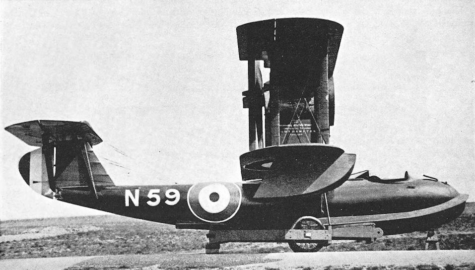
Supermarine Baby. The Hispano-Suiza-powered Baby in its later form with ailerons on upper and lower wings, and the small additional fin above the tailplane.
Tarrant Tabor
ALTHOUGH designed and built under a war-time contract and with war-time requirements in view, A the Tarrant Tabor was not completed until 1919. It was an aircraft in the same category as the Handley Page V/1500, for it was intended to bomb Berlin from bases in England.
The manufacturers of the Tabor were a firm of building contractors noted for the production of wooden buildings, and some of the plant was turned over to the manufacture of aircraft components after the outbreak of war. For their first attempt to produce an aircraft of their own, the Tarrant company could hardly have built anything more ambitious than the Tabor.
It was a vast triplane which rivalled the German Riesenflugzeuge in sheer size. The central mainplane was considerably larger than the top and bottom wings, and it alone was fitted with ailerons. The fuselage was a monocoque structure of circular cross-section and good aerodynamic form; it was the largest monocoque fuselage (as distinct from flying boat hull) which had been made in Britain up to that time.
There was a biplane tail-unit with twin fins and horn-balanced rudders. There were two elevators: one was a horn-balanced surface attached to the lower tailplane; the other was midway between the tailplanes. A third movable surface was attached to the upper tailplane, but was a trimming surface only, actuated by means of a handwheel in the cockpit.
The Tabor was designed to have four Siddeley Tiger engines which were expected to develop 600 h.p. each. The Tiger fell short of expectations, however, and none were available when the airframe was nearing completion. The nearest equivalent total horse-power could be provided by using six Napier Lions, and that alternative was adopted. Four of the engines were mounted in two tandem pairs between the middle and bottom wings; the tractor engines drove two-bladed airscrews, the pushers four-bladers of smaller diameter. The other two engines were mounted as tractor units between the top and middle wings, and their thrust line must have been quite 27 feet above ground level.
The undercarriage was a massive affair, each unit of which had three wheels mounted close together on a common axle.
The estimated performance of the Tabor was quite good, and its load included sufficient fuel for eight hours’ flying in normal cruising conditions or, if only four engines were used, for twelve hours at an average speed of 91 1/2 m.p.h.
The aircraft was built in close collaboration with the Royal Aircraft Establishment and was assembled in the balloon shed at Farnborough, whence it had to be brought out sideways on special trucks running on rails.
On May 26th, 1919, the Tabor was prepared for its first flight. The first pilot was Captain F. G. Dunn, A.F.C., and the second pilot was Captain P. T. Rawlings, D.S.C. After taxying trials, Dunn increased speed, lifted the tail from the ground, and opened up the two upper engines. The Tabor immediately turned over on to its nose, which collapsed, and finished up resting on the leading edges of the wings with fuselage vertical. Dunn and Rawlings sustained fatal injuries.
At the inquest Mr Tarrant disclosed that his consulting engineers had disagreed with the R.A.E. calculations based on tests of a model of the Tabor, and had thought that the aircraft would be very tail-heavy. Mr Tarrant had wanted independent confirmation of the test results from the National Physical Laboratory but, after further discussions with R.A.E. officials, had been convinced that his consulting engineers were wrong. Perhaps it was a residual doubt that had led to the carrying of about half a ton of lead shot in the nose as ballast, though that alone could hardly have caused the disaster. It seems probable that the sudden thrust exerted by the high top engines may have sufficed to push the machine on to its nose.
SPECIFICATION
Manufacturers: NT G. Tarrant, Ltd., Byfleet, Surrey.
Power: Six 450 h.p. Napier Lion.
Dimensions: Span: middle 131 ft 3 in.; top and bottom 98 ft 5 in. Length: 73 ft 2 in. Height: 37 ft 3 in. Chord: 15 ft 2 in. Gap: 14 ft 9 in. (both). Dihedral: 4. Incidence: 3. Span of tail: 30 ft. Wheel track: 34 ft 5 in. between centres. Airscrew diameter: tractors 12 ft 6 in.; pushers 10 ft 7 1/4 in.
Areas: Wings: 4,950 sq ft. Ailerons: each 105 sq ft, total 210 sq ft. Tailplanes: each 184 sq ft, total 368 sq ft. Elevators: upper 54 sq ft, lower 81 sq ft. Area of top trimming elevator: 81 sq ft. Fins: each 42 sq ft. Rudders: each 31 sq ft.
Weights: Empty: 24,750 lb. Military load: 5,130 lb. Crew: 1,080 lb. Fuel and oil: 13,712 lb. Loaded: 44,672 lb.
Estimated Performance: Maximum speed: over 110 m.p.h. Climb to 5,000 ft: 10 min 30 sec; to 10,000 ft:
33 min 30 sec; to 13,000 ft: just over 60 min. Ceiling: 13,000 ft. Endurance: normal, 8 hours; maximum, 12 hours.
Tankage: Petrol: 1,600 gallons. Oil: 92 gallons.
Armament: No details were released, but the weight of bombs and bomb gear was 4,650 lb, which represented a load equivalent to about forty 112-lb bombs.
Serial Numbers: F.1765-F.1766. The second machine was not built.
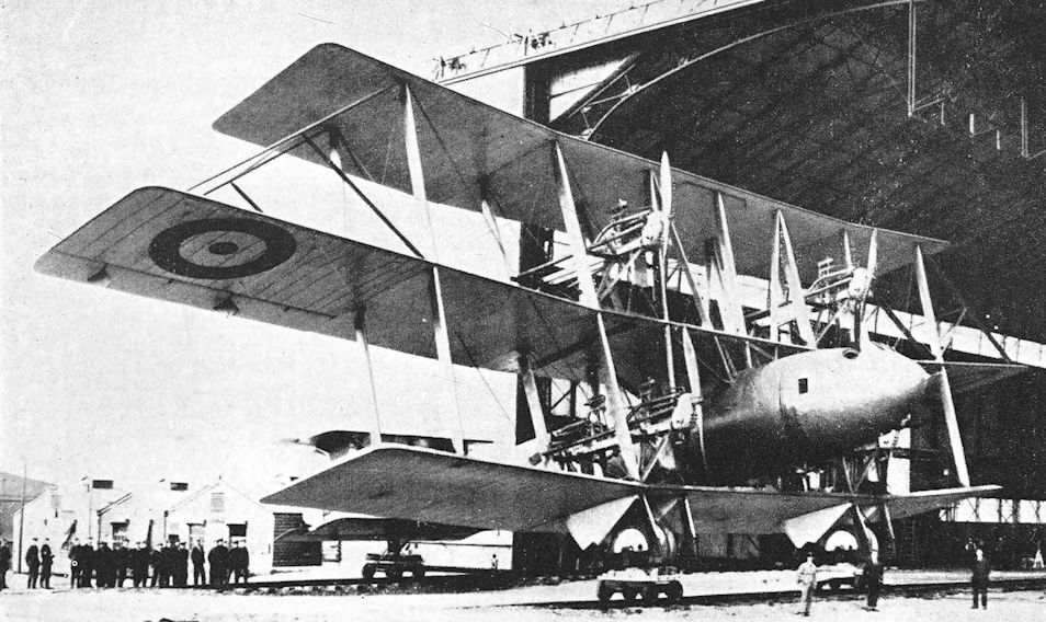
The Tarrant Tabor after being brought out from the balloon shed at Farnborough. The small trucks and their rails can be seen.
Vickers F.B.5
THE great Vickers concern had begun to take an active interest in aviation from the early part of 1911. Captain H. F. Wood was appointed technical adviser to the firm, and it was because of his enterprise that the company produced a series of monoplanes, the earliest of which were based upon the French R.E.P. design.
At the 1913 Aero Show which opened at Olympia in February of that year,. Vickers Ltd. displayed one of their monoplanes; but of far greater significance was a new pusher biplane exhibited on the same stand.
The latter aircraft had heavily staggered wings and was powered by one of the new 60-80 h.p. Wolseley engines. Let into the nose of the nacelle was a Maxim belt-fed machine-gun which was capable of limited movement.
This aeroplane was the forerunner of one of the first true fighting aircraft ever possessed by the British forces. Throughout 1913 and the first half of 1914 further variations on the basic theme appeared: later versions had the 100 h.p. Gnome Monosoupape engine; the staggered wings were not repeated; various nacelle shapes were tried, as were wing designs, some with ailerons, others with warping. But the gun was always there in the nose of the nacelle, whence it had uninterrupted forward fire.
All the early Vickers gun-carriers were armed with a Maxim or Vickers belt-fed gun on a kind of ball and socket mounting, and it came to be realised that this arrangement was not ideal. The nature of the mounting prevented the taking of any kind of aim and limited the movement of the gun; within the cockpit the gun and its belt of ammunition gave rise to some difficulties of stowage.
By 1914, therefore, when the Vickers F.B.4 appeared, a change had been made in the armament: there was provision for carrying a Lewis drum-fed machine-gun on a kind of spigot just in front of the gunner’s cockpit. Thus he was provided with a free and flexible weapon. The F.B.4 was the design from which the F.B.5 was developed.
The aircraft’s full designation signified Vickers Fighting Biplane No. 5. The two-bay wings were of equal span; the large rectangular tailplane was at the level of the upper tail-booms; the undercarriage embodied two longitudinal skids; and the engine was a 100 h.p. Gnome Monosoupape. The nacelle was neater than that of any earlier Vickers gun-carrier and had an aluminium nose. It offered scant protection to the observer, whose Lewis gun was carried on a pillar mounting at the extreme front of his cockpit. At least one F.B.5 had a modified nacelle with a more pointed “chin”, but this did not become a standard feature.
Vickers Ltd. were convinced of the value of their two-seat fighter and were equally certain that war was imminent. With a degree of foresight that has only one equal in history (namely, the laying down in 1939 of Hawker Hurricanes that had not been ordered by the Government), Major Wood began construction of a batch of fifty F.B.5s in 1914.
The F.B.5 was tested at Farnborough in July 1914 and was well reported on. Official orders were then placed for the type; but not without misgiving, for it was an untried design powered by what was then an untried engine. In its earliest form the F.B.5 had a rudder with a straight vertical trailing edge, but an enlarged rudder of rounded outline was soon substituted and remained standard.
At the outbreak of war the R.N.A.S. had on its strength a Vickers biplane with a Monosoupape engine: whether this was an F.B.5 or one of its immediate predecessors is uncertain.* The first F.B.5 to go to France arrived there on February 5th, 1915, and others soon followed. One was with No. 16 Squadron on March 10th, 1915, but most of the others were allotted to No. 5 Squadron. In the R.F.C. the F.B.5 was known as the Vickers Gun Bus.
* To the R.N.A.S. the Vickers F.B.5 was known as Vickers Type 32, from the first machine’s serial number. Two batches numbered 861-864 and 3595-3606 were later supplied to the R.N.A.S.
But the F.B.5s which went to France were not the first to go into action against enemy aircraft. On Christmas Day, 1914, a German seaplane came in over Sheerness at 12.35 p.m. and flew up the Thames as far as Erith, pursued by three R.N.A.S. aeroplanes from Eastchurch and Grain. One of the first Vickers F.B.5s went up from Joyce Green to engage the enemy, but the engine was troublesome, the Lewis gun jammed, and the gallant gunner had his hands frost-bitten - in his haste he had forgotten his gloves. The enemy escaped.
The early Gnome Monosoupapes gave a good deal of trouble. Those fitted to the Vickers F.B.5s were British-made and were by no means reliable. Writing in April, 1915, Lieutenant-Colonel H. R. M. Brooke-Popham reported: “A case has recently been brought to my notice where a pilot has had 22 forced landings in 30 flights in a Vickers machine.” Fortunately the troubles were not chronic or incurable, and once the Monosoupape was understood it gave good service.
The Vickers F.B.5 did not at first form the exclusive equipment of any squadron, but a few machines were attached to units with the intention of providing fighter protection for the reconnaissance aircraft.
On April 8th, 1915, No. 7 Squadron arrived in France with two Flights of R.E.5s and one of Vickers F.B.5s, but the Vickers were quickly replaced by Voisins. By May 9th, No. 5 Squadron was the only unit with any F.B.5s on strength: its equipment on that date consisted of five Vickers F.B.5s, six Avro 504s and one Martinsyde S.1.
On July 25th, 1915, the first homogeneous fighter squadron to join the B.E.F. arrived in France. It was No. 11 Squadron, R.F.G., and it was equipped throughout with Vickers F.B.5s. This famous squadron did not confine its activities to fighting, but also carried out long reconnaissances, photography and occasional artillery observation flights.
With No. 11 Squadron the Vickers F.B.5 gave an excellent account of itself, despite its meagre performance. The pilots found that it was immensely strong, for the basic structure, including the tailbooms, was of steel tubing. The number of enemy aircraft shot down by the F.B.5s was not large, but enemy pilots had a wholesome respect for the sturdy old pusher and seldom tried conclusions with it.
On November 7th, 1915, Second Lieutenant G. S. M. Insall of No. 11 Squadron won the Victoria Cross for an action in a Vickers F.B.5. He and his observer, Air Mechanic T. H. Donald, forced down an Aviatik two-seater and completed its destruction by dropping an incendiary bomb on it. Crossing the lines at low level, the Vickers came under heavy fire; its tank was pierced and the engine stopped. Insall landed 500 yards inside the French lines, and his F.B.5 was immediately shelled by the enemy. Fortunately the machine was not hit, and after nightfall it was repaired. At dawn next day Insall flew it back to his squadron’s aerodrome.
On November 19th, 1915, No. 18 Squadron arrived in France equipped with Vickers F.B.5s, but had them for a short period only before being re-equipped with F.E.2b’s. By that time the Vickers had been outclassed by the Fokker Monoplane with its synchronised machine-gun. Indicative of the circumstances were the experiments made with one of the F.B.5S of No. 11 Squadron early in 1916: these were the earliest attempts to produce a double-yoked pair of Lewis guns.
No. 11 Squadron still had four Vickers F.B.5S on its strength on July 1st, 1916, but by then the old warrior was hopelessly outmoded. After its withdrawal from fighting duties the F.B.5 gave excellent service with the training squadrons, for it was a viceless flying machine.
The only known experimental variants of the F.B.5 appeared in the summer of 1915. An armoured version of the type was delivered to Upavon; it was powered by the first 110 h.p. Clerget engine to reach this country. The engine gave a good deal of trouble, however, and the armoured F.B.5 did not go into production. Two experimental F.B.5s were supplied to the Admiralty. They were numbered 1534 and 1535, and were powered by the 150 h.p. Smith radial engine: the first machine was accepted at Eastchurch on August 7th, 1915. Apparently the two aircraft differed slightly, but neither was developed.
SPECIFICATION
Manufacturers: Vickers, Ltd. (Aviation Department), Imperial Court, Basil Street, Knightsbridge, London, S.W.
Power: 100 h.p. Gnome Monosoupape. 110 h.p. Clerget. 150 h.p. Smith Static.
Dimensions: Span: 36 ft 6 in. Length: 27 ft 2 in. Chord: 5 ft 6 in. Gap: 6 ft. Stagger: nil. Dihedral: 1°. Incidence: 4° 30'. Wheel track: 5 ft 10 1/2 in.
Areas: Wings: upper 197 sq ft, lower 185 sq ft, total 382 sq ft. Ailerons: each 14-25 sq ft, total 57 sq ft. Tailplane: 56 sq ft. Elevators: 24-6 sq ft. Fin: 8-5 sq ft. Rudder: 13-25 sq ft.
Weights: Empty: 1,220 lb. Military load: 40 lb. Crew: 360 lb. Fuel and oil: 430 lb. Loaded: 2,050 lb.
Performance: Maximum speed at 5,000 ft: 70 m.p.h. Climb to 5,000 ft: 16 min. Service ceiling: 9,000 ft. Endurance: 4 1/2 hours.
Armament: One Lewis machine-gun on pivoted mounting at front of observer’s cockpit, occasionally augmented by a rifle or revolver. One Vickers F.B.5 of No. 11 Squadron had an experimental installation of a pair of Lewis guns. Light bombs could be carried.
Service Use: Western Front: R.F.C. Squadrons Nos. 2, 5, 7, 11, 16 and 18; No. 1 Squadron, R.N.A.S. (had one Vickers Fighter on February 26th, 1915). Training: No. 10 Reserve Squadron, Joyce Green; No. 24 Squadron, Hounslow.
Production and Allocation: Official statistics indicate that 241 Vickers F.B.5S were distributed to units of the R.F.C. It seems possible, however, that that total may include re-allocations to training units, to which 131 were delivered. To the squadrons with the B.E.F. went 109 F.B.5S: sixty in 1915 and forty-nine in 1916; and one went to the Middle East in 1917.
Serial Numbers: 32. 861-864: ordered under Contract No. C.P.O.2132/14/X(A). 865-872: originally ordered for Admiralty under Contract No. C.P.O.2132/14/X(A) but transferred to R.F.C. 1534-1535: supplied to Admiralty with 150 h.p. Smith engine under Contract No. 47886/15/X(A). 1628-1639: ordered under Contract No. A.2705 (M.A.3). 1640-1651: ordered under Contract No. A.2866 (M.A.3). (Apparently the serial numbers 1648-1651 were re-allocated after the cancellation of the B.E.10s for which the numbers were originally allotted.) 2340-2347: ordered under Contract No. A.2978. 2870-2883: ordered under Contract No. A.2974 (M.A.3). 3595-3600: ordered under Contract No. C.P.58733/15/X(A). 3601-3606: ordered under Contract No. 87/A/210 (M.A.3). 4736: ordered under Contract No. A.2978. 5618-5623 and 5649-5692: ordered under Contract No. 87/A/107.

An early Vickers F.B.5 with the original form of rudder.

Production F.B.5 with the enlarged rudder.

Vickers F.B.5 with modified nacelle.
Vickers F.B.7
THE Vickers F.B.7 was a contemporary of the E.S.1, and made its first flight in August, 1915. It was the first Vickers twin-engined type, and was designed as a heavy gun-carrier: its armament consisted of a Vickers one-pounder quick-firing gun mounted in the nose of the fuselage. The gun was tended by the occupant of the forward cockpit.
The F.B.7 was an ungainly biplane, characterised by a deep, low-slung fuselage of unusual design. The forward portion was of rectangular cross-section, but had a deep keel fairing. The bottom member of this fairing ran back to the stern-post, and the rear part of the fuselage was of inverted triangular cross-section. The pilot’s cockpit was situated behind the mainplanes, several feet away from the gunner.
The wings had two bays of struts, and only the enormous extensions of the upper mainplanes were rigged with dihedral. All interplane struts and engine bearers were of steel tube. The engines were two Gnome Monosoupape rotaries mounted midway in the gap between the wings, and rotating in opposite directions to neutralise torque reaction. The F.B.7 appeared with two different engine installations. In one case the engines were carried, completely uncowled, on overhung mountings; in the other they were encircled by casings designed to catch flying oil. In the latter case, fore-and-aft mountings were used, and the cowlings faired off into bulky nacelles of circular cross-section.
The tail-unit was conventional: there was no fixed fin, however, and the large rudder was a balanced surface.
The War Office ordered a dozen F.B.7s, and production had begun when it was learned that there was a shortage of Monosoupape engines. Vickers Ltd. were asked to fit two 80 h.p. Renault engines as substitutes, and at least one machine had that power plant. The arrangement of the interplane struts was altered from that of the prototype to accommodate the vee-eight engines, and a completely re-designed fuselage was fitted. It was a more conventional structure of rectangular cross-section, and the pilot’s cockpit was situated in front of the wings. The rigging of the mainplanes was slightly altered: the dihedral of the upper wings started at the inboard interplane struts.
The production version was re-designated F.B.7A. On test it was found that the loss of 40 nominal h.p. had proved so detrimental to the machine’s performance that Vickers Ltd. requested the cancellation of the contract. This was agreed, and no further development took place.
SPECIFICATION
Manufacturers: Vickers, Ltd. (Aviation Department), Imperial Court, Basil Street, Knightsbridge, London, S.W.
Power: Two 100 h.p. Gnome Monosoupape; two 80 h.p. Renault.
Dimensions: Span: upper 59 ft 6 in., lower 37 ft 6 in. Length: 36 ft. Chord: upper 8 ft 3 in., lower 6 ft. Gap: 7 ft 4 in. Stagger: 11 in. Dihedral: 3. Incidence: 3.
Areas: Wings: upper 459 sq ft, lower 181 sq ft, total 640 sq ft. Ailerons: each 46-5 sq ft, total 93 sq ft. Tailplane: 42 sq ft. Elevators: 28-5 sq ft. Rudder: 20 sq ft.
Weights and Performance (Gnome engines): Weight empty: 2,136 lb. Military load: 256 lb. Crew: 360 lb. Fuel and oil: 444 lb. Loaded: 3,196 lb. Maximum speed at 5,000 ft: 75 m.p.h. Climb to 5,000 ft: 18 min. Endurance: 2 1/2 hours.
Armament: One one-pounder Vickers automatic gun in forward cockpit.
Serial Numbers: The numbers 1616-1627, allotted for Vickers Fighting Biplanes other than F.B.5s, may have been for F.B.7s. They were ordered under Contract No. A.2614 (M.A.3). The F.B.7A was numbered 5717 and was ordered under Contract No. 87/A/39.
Vickers F.B.8
THE fighting success of the Vickers F.B.5 was ample proof of the effectiveness of a good aeroplane from which a machine-gun could be used in practical fashion, but it was obvious that better performance would be a great asset.
In an attempt to produce a gun-carrying aeroplane with the necessary performance the Vickers F.B.8 was built; to obtain the power needed, twin engines were fitted. As on the F.B.7, the engines were two opposite-handed Gnome Monosoupapes. For a twin-engined aeroplane the F.B.8 was remarkably small; and it was a much more business-like machine than the F.B.7.
The fuselage was a conventional structure in which the gunner occupied a cockpit in the extreme nose and the pilot sat behind the wings. The wide-track undercarriage was somewhat similar to that of the F.B.7, and had a large central skid. The two-bay wings were not quite equal in span, and the lower was of narrower chord than the upper. The engines were mounted in mid-gap; each was encircled by a ring to catch oil. The tail-unit was generally similar to that of the F.B.7: again there was no fin, and the single rudder was aerodynamically balanced.
The F.B.8 was built in November, 1915, and proved to be the fastest twin-engined aeroplane of that year. Despite its good performance, however, it was obviously too bulky to be effective as a fighting machine, and the distance between pilot and gunner was too great to allow of effective cooperation between them. The type was therefore abandoned, and the decision to do so was doubtless hastened or confirmed by the knowledge that the Vickers-Challenger interrupter gear then being tested offered a better prospect of providing effective armament.
SPECIFICATION
Manufacturers: Vickers, Ltd. (Aviation Department), Imperial Court, Basil Street, Knightsbridge, London, S.W.
Power: Two 100 h.p. Gnome Monosoupape.
Dimensions: Span: upper 38 ft 4 in., lower 36 ft 8 in. Length: 28 ft 2 in. Chord: upper 7 ft, lower 5 ft 9 in. Gap: 6 ft. Stagger: 10 in. Dihedral: 2. Incidence: 3.
Areas: Wings: upper 262 sq ft, lower 206 sq ft, total 468 sq ft. Ailerons: each 24-25 sq ft, total 97 sq ft. Tailplane: 35 sq ft. Elevators: 25 sq ft. Rudder: 13 sq ft.
Weights and Performance: Weight empty: 1,840 lb. Military load (including crew): 370 lb. Fuel and oil: 490 lb. Loaded: 2,700 lb. Maximum speed at 5,000 ft: 98 m.p.h. Climb to 5,000 ft: 10 min. Ceiling: 14,000 ft. Endurance: 3 hours.
Armament: One Lewis machine-gun on movable mounting in front cockpit.

Flanders-designed E.F.B.7 in original form with Gnome monosoupape engines, and pilot behind wings.
Vickers F.B.7 with cowled engines on fore-and-aft mountings, and Vickers quick-firing gun mounted on the front cockpit.
Vickers F.B.7 with cowled engines on fore-and-aft mountings, and Vickers quick-firing gun mounted on the front cockpit.

Vickers F.B.7 with uncowled engines on overhung mountings in 1915.

Vickers F.B.7A. This illustration shows the completely revised fuselage with the pilot’s cockpit ahead of the wings, the modified wing rigging, and the two Renault engines which distinguished the Vickers F.B.7A.

Pierson development of E.F.B.7 was this E.F.B.8, designed as a twin-engined fighter for the Lewis gun seen parked against the nose; the oil slinger rings around the Gnome rotary engines are also of interest.
Vickers E.S.1 and E.S.2
THE little single-seat tractor scout which was designated Vickers E.S.1 was, in its day, more popularly known as the Barnwell Bullet. It had been designed and largely constructed by Harold Barnwell, that great pilot who tested so many Vickers products at Joyce Green.
The E.S.1 appeared in August, 1915, and showed an astonishing turn of speed on the 100 h.p. of its Gnome Monosoupape engine. Its performance was attributable to clean design. The structure of the fuselage was basically a conventional wooden one, but full fairings were applied to preserve the circular cross-section of the engine cowling right back to the tail. The single-bay wings had square tips; so also had the tailplane, but the low aspect-ratio fin and rudder assembly was of oval outline.
Naturally, the E.S.1’s performance commended it to the R.F.C., and it was sent overseas for Service trials. It was flown to St. Omer by Lieutenant R. Howitt who, on arrival, made it known that the view from the cockpit was not good: the rounded sides of the fuselage deprived the pilot of any downwards view, whilst upwards and forwards his field of view was obscured by the upper wing. The complete cowling of the engine gave rise to cooling difficulties, and more than once the E.S.1’s destruction by fire was only narrowly averted. Ultimately it was crashed by Captain P. H. L. Playfair.
The good performance of the E.S.1 encouraged Vickers to produce a similar machine which embodied a number of improvements. The new type, of which two examples were built, was designated E.S.2, and the first was flying in September, 1915. During that month it was demonstrated to H.M. King George V on the occasion of a royal visit to Vickers’ Crayford works. The most obvious difference between the E.S.2 and its predecessor lay in the shape of the wing-tips, which were pleasantly rounded. In an attempt to improve the pilot’s view a large cut-out was made in the centre-section. The underside of the E.S.2’s fuselage was left flat, whereas that of the E.S.1 had had a full-length fairing. The engine was a 110 h.p. Clerget, but the type was also tested with a 110 h.p. Le Rhone. The engine cowling of the E.S.2 was of shorter chord than that of the E.S.1.
In 1915 the Vickers-Challenger interrupter gear for machine-guns was developed, and the E.S.2 was armed with a single Vickers gun equipped with the interrupter gear. It was still far from ideal as a fighting aircraft, however, because its tubby fuselage obstructed such a large part of the pilot’s view. The type provided the basis for the design of the later Vickers F.B.19 fighter.
SPECIFICATION
Manufacturers: Vickers Ltd. (Aviation Department), Imperial Court, Basil Street, Knightsbridge, London, S.W.
Power: E.S.1: 100 h.p. Gnome Monosoupape. E.S.2: 110 h.p. Clerget; 110 h.p. Le Rhone.
Dimensions: Span: E.S.1, 24 ft 4 1/2 in.; E.S.2, 24 ft 5 1/2 in. Length: E.S.1, 20 ft 3 in.; E.S.2 (Clerget), 20 ft 3 in., E.S.2 (Le Rhone), 19ft 10 in. Height: 8 ft. Chord: 4 ft 9 in. Gap: E.S.1, 4 ft; E.S.2, 4 ft 3 in. Stagger: nil. Dihedral: E.S.1, originally nil, later 1°; E.S.2, 1°. Incidence: 0°. Span of tail: 10 ft. Wheel track: 4 ft 3 1/2 in. Airscrew diameter: 8 ft 6 1/2 in.
Areas: Wings: upper ng sq ft, lower 102 sq ft, total 215 sq ft. Ailerons: each 5-5 sq ft, total 22 sq ft. Tailplane: 17-5 sq ft. Elevators: 12-5 sq ft. Fin: 4-2 sq ft. Rudder: 6-4 sq ft.
Armament: The E.S.1 was unarmed. The E.S.2 was fitted with a fixed, forward-firing Vickers machine-gun, mounted on the port upper longeron and recessed into the top-decking. This gun was synchronised by Vickers (Challenger) interrupter gear to fire through the arc of the revolving airscrew.
Service Use: The E.S.1 was flown at St. Omer late in 1915.
Serial Numbers: 7509: E.S.1. 7759-7760: E.S.2. All were ordered under Contract No. 87/A/544.
Weights (lb) and Performance:
Aircraft E.S.1 E.S.2 (Clerget) E.S.2 (Le Rhone)
No. of Trial Report - M.2 M.45
Date of Trial Report - May, 1916 May, 1916
Type of airscrew used on trial - Vickers Series 26 Vickers Series 26
Weight empty 843 981 1,052
Military load nil 80 80
Pilot 18.0 180 180
Fuel and oil 272 261 288
Loaded 1,295 1,502 1,600
Maximum speed (m.p.h.) at
ground level - I 12-2 117-2
5,000 ft 114 109 -
8,000 ft - 106 109
m. s. m. s. m. s.
Climb to
1,000 ft - - - - 1 00 0 55
2,000 ft - - 2 06 I 40
3,000 ft - - 3 18 2 50
4,000 ft - - 5 06 3 55
5,000 ft 6 40 6 25 5 15
6,000 ft - - 8 25 6 45
7,000 ft - - 10 12 8 40
8,000 ft - - 12 40 10 40
9,000 ft - - 15 12 12 40
10,000 ft 18 00 18 00 14 45
11,000 ft - - - - 17 10
12,000 ft - - 25 15 20 00
13,000 ft - - 37 00 23 30
14,000 ft - - - - 28 30
15,000 ft - - - - 32 30
16,000 ft - - - - 37 00
Service ceiling (feet) 15,500 15,500
Endurance (hours) 3 2 (at 8,000 ft) 3 1/4 (at 8,000 ft)
Tankage: Petrol (gallons) - 28 30
Oil (gallons) - 6-6 8

The sole Vickers E.S.1, No 7509, showing the attempt to fully cowl a rotary engine.

Vickers E.S.1 in R.F.C. markings for official trials at the CFS, Upavon, with slightly modified engine cowling.

Vickers E.S.2. This illustration shows the shallower fuselage, rounded wing-tips, and recessed Vickers gun which distinguished the E.S.2.
Two examples of the E.S.1 Mk II were built and, also known as E.S.2s, were briefly tested by the RFC.
Two examples of the E.S.1 Mk II were built and, also known as E.S.2s, were briefly tested by the RFC.
Vickers F.B.9
THE Vickers F.B.9, which first appeared in December, 1915, was an improved version of the F.B.5. It was similar to the F.B.5 in general appearance and in construction; but both mainplanes and tailplane had rounded tips, a plain vee undercarriage replaced the original twin-skid structure, and Rafwires replaced cables in the interplane bracing.
The nacelle was of rather neater appearance, and the gunner’s cockpit was fitted with an improved form of gun mounting which could be rotated and thereby enhanced the gun’s flexibility. The standard engine remained the 100 h.p. Gnome Monosoupape, and the various refinements gave the F.B.9 a maximum speed 10 m.p.h. higher than that of the F.B.5.
The shape of the nacelle underwent some changes. Originally the side elevation of the nose was D-shaped, but this was later replaced by a more pointed form which gave a long bottom line to the nacelle. At least one F.B.9 with the later nacelle had a 110 h.p. Le Rhone engine.
It seems rather doubtful whether the F.B.9 was used operationally. The only official reference to its use treats it as a type distinct and different from the F.B.5, and states that the F.B.9 was issued to training units only. Several of those used for training purposes were fitted with dual control, and others were given a Scarff ring-mounting on the front cockpit for training observers in aerial gunnery.
SPECIFICATION
Manufacturers: Vickers Ltd. (Aviation Department), Imperial Court, Basil Street, Knightsbridge, London, S.W.
Power: 100 h.p. Gnome Monosoupape; 110 h.p. Le Rhone.
Dimensions: Span: 33 ft 9 in. Length: 28 ft 5 1/2 in. Height: 11 ft 6 in. Chord: 5 ft 6 in. Gap: 6 ft. Stagger: nil. Dihedral: 1° 30'. Incidence: 3°. Span of tail: 14 ft 3 in. Wheel track: 5 ft 10 1/2 in. Airscrew diameter: 9 ft.
Areas: Wings: upper 177 sq ft, lower 163 sq ft, total 340 sq ft. Ailerons: each 14-25 sq ft, total 57 sq ft. Tailplane: 54 sq ft. Elevators: 24-6 sq ft. Fin: 8-5 sq ft. Rudder: 13-25 sq ft.
Weights and Performance (with Gnome engine): Weight empty: 1,029 lb. Military load: 63 lb. Crew: 360 lb. Fuel and oil: 440 lb. Loaded: 1,892 lb. Maximum speed at ground level: 82-6 m.p.h.; at 6,500 ft: 79 m.p.h.; at 10,000 ft: 75 m.p.h. Climb to 1,000 ft: 2 min 30 sec; to 2,000 ft: 5 min 20 sec; to 3,000 ft: 7 min 45 sec; to 4,000 ft: 10 min 30 sec; to 6,500 ft: 19 min; to 10,000 ft: 51 min. Service ceiling: 11,000 ft. Endurance: 5 hours.
Tankage: Petrol: 50 gallons. Oil: 8 gallons.
Armament: One Lewis machine-gun on Vickers ring-mounting or Scarff ring-mounting on forward cockpit.
Service Use: Training: No. 6 Reserve Squadron, Catterick; No. 10 Reserve Squadron, Joyce Green; No. 188 Squadron, formed at Retford, March, 1918.
Production and Allocation: Serial numbers were allotted for a total of ninety-five Vickers F.B.9s. A total of fifty were distributed to R.F.C. training units.
Serial Numbers: 5271-5290: built under Contract No. 87/A/341. A.1411-A.1460: built at Vickers’ Weybridge works, under Contract No. 87/A/485. A.8601-A.8625: built at Weybridge, under Contract No. 87/A/485.
Notes on Individual Machines: 5274 and 5275 were used by No. 6 Reserve Squadron. A.1412: No. 10 Reserve Squadron.

Vickers F.B.9 with early form of nose.

Vickers F.B.9 with lengthened nose and 110 h.p. Le Rhone engine, showing rounded wing tips and tailplane, sharper nose and cleaner lines, leading to the appellation of the Streamline Gunbus.
Vickers F.B.11
THIRD of the three designs to be built to the R.F.C.’s specification for a long-range escort fighter, the Vickers F.B.11 of 1916 was basically a much more conventional aeroplane than its competitors, the Armstrong Whitworth F.K.12 and the Sopwith L.R.T.Tr.
The F.B.11 was a large tractor biplane powered by a 250 h.p. Rolls-Royce engine. The wings were of equal span and wide gap, and were remarkable for having only a single bay of interplane bracing. The upper centre-section was very wide: it overhung the centre-section struts by an appreciable amount on each side. The outermost portions of the lower wings were braced by additional landing wires from the tops of the interplane struts.
The engine was enclosed in a clean though somewhat bulky cowling; the radiator was installed behind the engine and within the fuselage. The pilot sat in line with the trailing edges of the wings, and there was a gunner immediately behind him. A second gunner occupied a lofty perch in a small nacelle which was built on to the leading edge of the centre-section and was supported by struts from the forward ends of the upper longerons.
The undercarriage looked like a massive version of that fitted to the Avro 504. Its strength was necessary, for the F.B.11 was considerably heavier than the larger F.B.7 had been. The tail-unit was of pleasing outline, and was strongly braced by substantial struts.
The idea of the escort fighter was officially abandoned when it became obvious that aerial warfare was developing along other lines. Vickers themselves hastened its abandonment with their own development of machine-gun interrupter gears.
SPECIFICATION
Manufacturers: Vickers Ltd. (Aviation Department), Imperial Court, Basil Street, Knightsbridge, London, S.W. The F.B.11 was built at Vickers’ Bexley works.
Power: 250 h.p. Rolls-Royce.
Dimensions: Span: 51 ft. Length: 43 ft. Chord: 9 ft. Gap: 9 ft. Stagger: nil. Dihedral: 2°. Incidence: 2°.
Areas: Wings: upper 440 sq ft, lower 405 sq ft, total 845 sq ft. Ailerons: each 28-25 sq ft. total 113 sq ft. Tailplane: 79-5 sq ft. Elevators: 55-5 sq ft. Fin: 19 sq ft. Rudder: 25 sq ft.
Weights and Performance: Weight empty: 3,340 lb. Military load: 189 lb. Crew: 540 lb. Fuel and oil: 865 lb. Loaded: 4,934 lb. Maximum speed at 5,000 ft: 96m.p.h.; at 10,000 ft: 815 m.p.h. Climb to 5,000 ft: 16 min 30 sec; to 10,000 ft: 55 min. Ceiling: 11,000 ft. Endurance: 4 1/2 hours.
Armament: One Lewis machine-gun on Scarff ring-mounting on rear cockpit. The top gunner was similarly armed.
Serial Numbers: A.4814-A.4815: ordered under Contract No. 87/A/439.

Vickers F.B.11.
Vickers F.B.12
THE little Vickers F.B.12 was designed early in 1916, presumably with a view to providing a replacement for the D.H.2s and F.E.8s which were then just beginning to appear in numbers. It was intended that the F.B.12 should be more powerful than any pusher scout which had been built up to that time, for it was designed to have a new type of radial engine, the Hart, which was credited with a power output of 150 h.p.
By the time the first F.B.12 airframe had been completed, no example of the Hart engine was available. In order to fly the aircraft an 80 h.p. Le Rhone rotary engine was installed, and with it the F.B.12 attained a speed of 95 m.p.h., a creditable performance in view of the greatly reduced power available. In this form the F.B.12 flew in June, 1916, and was officially tested in August.
The performance was attributable to clean design. In its original form the F.B.12 had a neat nacelle, faired out to a circular cross-section, and rather small wings with rounded tips. The nacelle was mounted midway between the mainplanes. The steel tube tail-booms converged in side elevation to meet at the rear spar of the tailplane. The squarish fin and rudder assembly was symmetrical about the tailplane. Both legs of the undercarriage vees were attached to the underside of the lower wing. The armament consisted of a single Lewis gun mounted within the nacelle but with a few inches of barrel protruding.
This version of the F.B.12 was also fitted with a 100 h.p. Gnome Monosoupape rotary engine.
The machine was later fitted with a set of new wings of greater span and area. The basic configuration of the aircraft remained unchanged, and the same tail-booms and tail-unit were used. The new mainplanes had angular, raked wing-tips, and the undercarriage was modified: a new and longer front leg was fitted to each vee, and its upper end was attached to the bottom longeron of the nacelle at the point of attachment of the foremost lower centre-section strut. The nacelle remained unchanged apart from a new windscreen, and the engine was the Gnome Monosoupape.
The design was again modified, perhaps with a view to production, because the structure was simplified by the introduction of a new and deeper nacelle with flat sides. The nacelle was again placed midway between the wings, which were of the revised form. A new fin and rudder assembly of higher aspect ratio and greater total area was fitted. This version of the aircraft was designated Vickers F.B.12C and, like the original design, was intended to have the 150 h.p. Hart radial engine. That power unit was still not available, however, and the F.B.12C was flown first with the 110 h.p. Le Rhone rotary engine and later with the 100 h.p. Anzani ten-cylinder radial.
One of the F.B.12 machines went to France for Service trials in December, 1916. It is reported that the F.B.12 in question had a Monosoupape engine, and it seems probable that it was the original aircraft with the larger wings. It was well reported on and was said to be at least equal to the D.H.2 and F.E.8, but presumably any advantages it may have had over existing types were not sufficiently great to justify putting it into production. At that time, too, the Sopwith Pup was coming into service and the S.E.5 and Camel were in prospect, all of which were superior to the F.B.12.
SPECIFICATION
Manufacturers: Vickers Ltd. (Aviation Department), Imperial Court, Basil Street, Knightsbridge, London, S.W.
Power: F.B.12: 80 h.p. Le Rhone; 100 h.p. Gnome Monosoupape. F.B.12C: 110 h.p. Le Rhone; 100 h.p. Anzani. Dimensions: Original form. Span: upper 26 ft, lower 24 ft. Length: 21 ft 6 in. Height: 8 ft 7 in. Chord: upper 5 ft, lower 4 ft. Gap: 4 ft 1 1/2 in. Stagger: 7-2 in. Dihedral: 3 30'. Incidence: 3. Span of tail: 12 ft. Airscrew diameter: 8 ft 6 1/4 in. Revised form and F.B.12C. Span: upper 29 ft 9 in., lower 26 ft 9 in. Length: Le Rhone, 21 ft 10 in.; Anzani, 22 ft. Height: Le Rhone, 8 ft 7 in.; Anzani, 8 ft 9 in. Chord: upper 5 ft, lower 4 ft. Gap: 4 ft 1 1/2 in. Stagger: 7 1/2 in. Dihedral: 3 30'. Incidence: 3.
Areas: Original form. Wings: upper 116 sq ft, lower 88 sq ft, total 204 sq ft. Ailerons: total area 32 sq ft. Tailplane: 18 sq ft. Elevators: 14-4 sq ft. Fin: 5-6 sq ft. Rudder: 6-7 sq ft. F.B.12C. Wings: upper 138 sq ft, lower 99 sq ft, total 237 sq ft. Ailerons: total area 42 sq ft. Tailplane: 18 sq ft. Elevators: 14-4 sq ft. Fin: 7-25 sq ft. Rudder: 6-7 sq ft.
Tankage: F.B.12, 80 h.p. Le Rhone. Petrol: 19 gallons. Oil: 3 1/4 gallons. F.B.12C, 110 h.p. Le Rhone. Petrol: 26 gallons. Oil: 8 gallons.
Armament: One forward-firing Lewis machine-gun mounted in the nose of the nacelle.
Weights (lb) and Performance:
Aircraft F.B.12 F.B.12C
Engine 80 h.p. Le Rhone Monosoupape Le Rhone Anzani
No. of Trial Report M.60 - M.99 M.I20
Date of Trial Report August, 1916 - May, 1917 July, 1917
Type of airscrew used on trial V.G.370 - Vickers Lang
Weight empty 845 885 927 953
Military load 80 80 80 80
Pilot 180 180 180 180
Fuel and oil 170 255 260 260
Loaded 1,275 1,400 1,447 1,473
Maximum speed (m.p.h.) at
ground level 92-4 - - -
4,000 ft 91 - - -
5,000 ft 88 93 - -
6,500 ft 86 - 87 86-5
7,000 ft 85-5 - - -
9,000 ft 82 - - -
10,000 ft - - 81 77
11,000 ft 80 - - -
m. s. m. s. m. s. m. s.
Climb to
1,000 ft 1 10 - - - - - -
2,000 ft 2 40 - - - - - -
3,000 ft 4 40 - - - - - -
4,000 ft 6 50 - - - - - -
5,000 ft 9 05 7 40 6 55 10 35
6,000 ft 11 35 - - - - - -
6,500 ft - - - - 9 40 15 25
7,000 ft 14 50 - - - - - -
8,000 ft 18 10 - - - - - -
9,000 ft 22 10 - - - - - -
10,000 ft 27 35 21 05 18 30 35 35
11,000 ft 34 50 - - - - - -
11,900 ft 44 00 - - - - - -
15,000 ft - - - - 48 20 - -
Service ceiling (feet) 11,500 14,000 14,500 10,000
Endurance (hours) 3 at 8,000 ft 3 3 1/4 3 3/4
Service Use: One machine (with 100 h.p. Gnome Monosoupape) went to France for operational trials in December, 1916; and an F.B.12C was delivered to a Home Defence unit in 1917.
Serial Numbers: A.7351-A.7368: F.B.12Cs ordered under Contract No. 87/A/997.
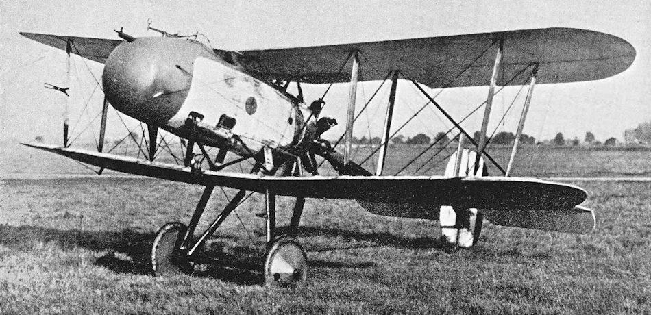
THE VICKERS F.B. 12 PUSHER SCOUT. - This particular machine is fitted with a 100 h.p. Gnome, but others of the same type were fitted with 80 h.p. and 110 h.p. le Rhones and 100 h.p. Anzanis
F.B.12C re-engined with 100 hp Gnome monosoupape; its distinguishing feature is the excellent pilot's view provided by the raised nacelle.
F.B.12C re-engined with 100 hp Gnome monosoupape; its distinguishing feature is the excellent pilot's view provided by the raised nacelle.
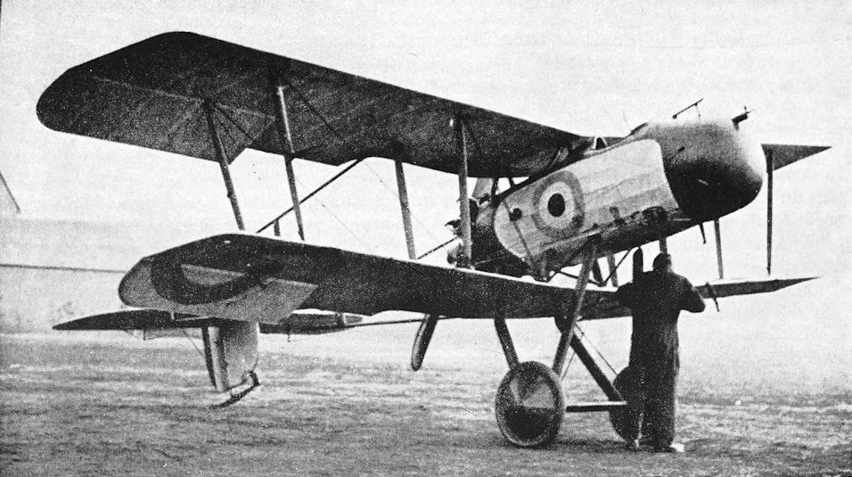
Vickers F.B.12 with modified wings and undercarriage.
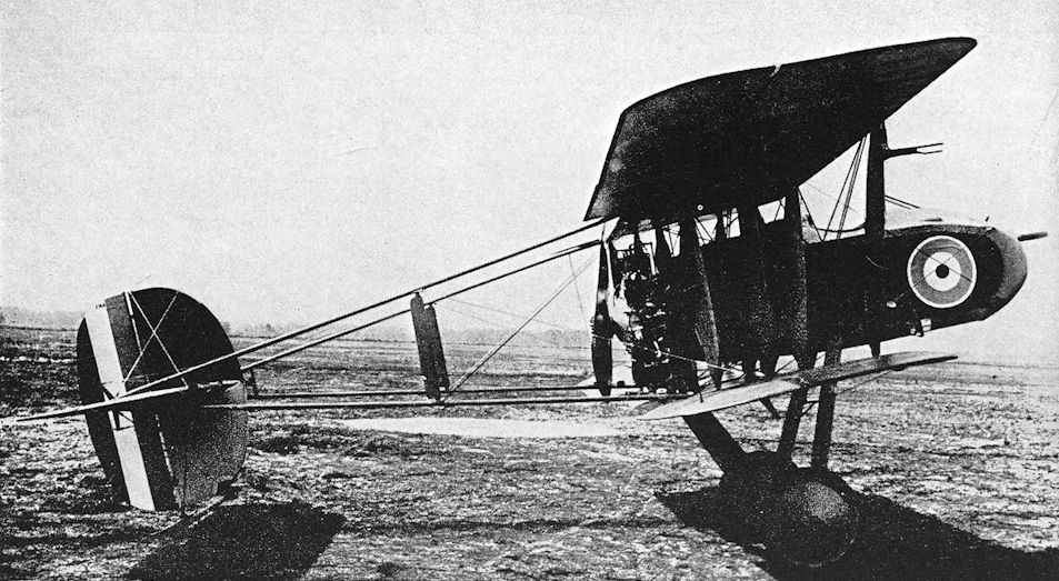
Vickers F.B.12C with Anzani radial engine.
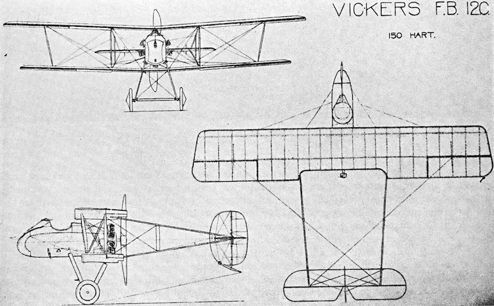
Vickers F.B.12C. General arrangement drawing of the F.B.12C with the 150 h.p. Hart radial engine.
Vickers F.B.14
THE Vickers F.B.14 was a two-seat fighter-reconnaissance biplane which was designed round the 230 h.p. B.H.P. engine. The airframe was ready for flight testing by the summer of 1916 but, as related in the history of the D.H.4, trouble was experienced in the development of the B.H.P. engine, and Vickers again found themselves in the position of having a new aeroplane but no engine for it.
Recourse was again made to the expedient of fitting a different type of engine. The selected power unit was the 160 h.p. Beardmore, which was of similar configuration to the B.H.P. and was likely to require the least amount of re-design of the airframe. The F.B.14 first flew with the Beardmore engine in August 1916. Performance was inevitably a good deal poorer than the original estimates; nevertheless 150 production machines were ordered.
The majority of the F.B.14s which were delivered were handed over without engines, for trouble was experienced with the 160 h.p. Beardmore. History does not vouchsafe the precise nature of the trouble as far as it affected the Vickers F.B.14, but it may have been one of supply quite as much as one of mechanical functioning. The 120 h.p. Beardmore was tried, but with it the F.B.14’s already poor performance was catastrophically reduced.
The Beardmore installation was a neat one, and the clean cowling gave quite a good aerodynamic entry for the fuselage, though the appearance was marred by the cumbersome exhaust manifold. The fuselage was constructed of steel tubing and had good lines; it terminated in a tail-unit which incorporated a low aspect-ratio fin and rudder of characteristic shape. The first production machines had no coaming between the cockpits, nor was there any decking behind the gunner’s cockpit. A later Beardmore-powered F.B.14, numbered A.3505, had a rounded top-decking on the fuselage and a coaming between the cockpits which incorporated a substantial head-rest for the pilot. This F.B.14 also had a modified engine cowling, and its fin had a straight leading edge in place of the gentle curve on standard machines.
The wings were of unequal span and chord. The upper mainplane was made in two halves which met at a trestle-shaped cabane structure. The pilot sat directly under the top wing, and transparent panels were let into it to give him some upward view. Most F.B. 14s also had transparent cut-outs in the roots of the lower wings. The single pair of interplane struts were raked outwards, and there were auxiliary mid-bay flying wires.
Other engines were fitted to the F.B. 14. After the 120 h.p. Beardmore had proved to be unsatisfactory, the 150 h.p. Lorraine-Dietrich was installed. This version of the design was designated F.B.14A. The Lorraine-Dietrich was a liquid-cooled vee-eight engine, and its installation in the F.B.14A was characterised by a frontal radiator and two converging exhaust stacks. The aircraft had the same inter-cockpit coaming and rear top-decking as A.3505, but the fin had the slightly rounded leading edge which appeared on the majority of F.B.14s.
Roughly contemporary with the F.B.14A was the F.B.14D, which was fitted with a 250 h.p. Rolls-Royce Mk. IV engine. That power unit was later known as the Eagle IV, and delivered 284 h.p.; the particular engine which was fitted to the F.B.14D had been tested to give 267 h.p. at 1,600 r.p.m. at ground level. The F.B.14D was quite different from any other F.B.14 sub-type, for it was fitted with new two-bay wings of increased span and area. The engine was enclosed in a rather bulky cowling and had a rectangular frontal radiator.
The performance of the F.B.14D was better than that of any other F.B.14 variant, but it was still rather poor for a potential fighter-reconnaissance aircraft and did not compare favourably with the contemporary Bristol Fighter. The F.B.14D went to Martlesham in March, 1917, and after completing its official tests there it was sent to Orfordness, where it was used in experimental armament work. On July 7th, 1917, the F.B.14D was one of the widely assorted number of British aeroplanes sent up to attack the Gotha formation which bombed London in daylight. The F.B.14D was able to overtake the retreating enemy formation and followed the Gothas all the way to Zeebrugge. Unfortunately the crew were unable to press home an attack because the experimental gunsights with which the machine was fitted proved to be useless.
The final variant of the F.B.14 design was the F.B.14F, which was fitted with the 150 h.p. R.A.F.4a engine. The installation of this air-cooled vee-twelve was generally similar to that of the R.E.8, but the performance of the F.B.14F proved to be rather better than that of the cleaner F.B.14, as the performance figures show. The F.B.14F had no fuselage top-decking, and the stagger of the mainplanes was greatly increased.
The F.B.14F was used in the course of a series of experiments conducted as part of an investigation into the spinning of aeroplanes. The official report on the part played by the F.B.14F gives a full explanation of the tests, and is as follows:
“It was impossible to spin the aeroplane with the fin then fitted, which was very long in shape. It would only do a peculiar kind of spiral. The fin was gradually stripped of its fabric and still the aeroplane practically would not spin, although one pilot managed to get two turns each way, great weight being felt first on the rudder and then on the control column in getting out. Then the fin was completely removed. The aeroplane was extremely nose heavy engine off, and the rudder felt heavy, probably owing to no fin being in front of it. One spin to the right was carried out from 5,000 feet, the aeroplane going in easily after being stalled with opposite aileron and rudder. It spun regularly, without jerks, and steeply nose down. In order to come out, first the rudder was pushed across. This needed great exertion on the pilot’s part, more than it feels safe to exert under normal conditions. The aeroplane ceased spinning immediately and tried to nose dive. There was a great pull on the control column needed to pull it out, apparently owing to the nose heaviness, to the shortness of the stick, and to the angle at which it is rigged.”
(Technical Report of the Advisory Committee for Aeronautics, 1919-20, Volume 2, page 482.)
Official records show that six Vickers F.B.14s were issued to Home Defence units in 1917. Apparently these were the only aircraft of their type to be on an operational footing, but no record contains any mention of combats in which F.B.14s were involved, apart from the F.B.i4D’s fruitless pursuit of the Gothas.
SPECIFICATION
Manufacturers: Vickers Ltd. (Aviation Department), Imperial Court, Basil Street, Knightsbridge, London, S.W.
Power: F.B.14: 160 h.p. Beardmore; 120 h.p. Beardmore. F.B.14A: 150 h.p. Lorraine-Dietrich. F.B. 14D: 250 h.p. Rolls-Royce Mk. IV (Eagle IV). F.B.14F: 150 h.p. R.A.F.4a.
Dimensions: Span: F.B.14, 14A, 14F, upper 39 ft 6 in., lower 33 ft; F.B.14D, upper 42 ft, lower 39 ft 6 in. Length: F.B.14, 28 ft 5 in.; F.B.14A, 26 ft 6 in.; F.B.14D, 30 ft 8 in.; F.B.14F, 27 ft. Height: F.B.14 and 14A, 10 ft; F.B.14D, 10 ft 3 in.; F.B.14F, 10 ft 6 in. Chord: upper 6 ft 6 in., lower 6 ft. Gap: 6 ft. Stagger: F.B.14, 14A, 14D, 3 in.; F.B.14F, 1 ft 11 in. Dihedral: 2. Incidence: 3. Sweepback (F.B.14A only): 3. Span of tail: 16 ft. Wheel track: 5 ft 5 in. Airscrew diameter: F.B. 14, 9 ft 6 in.
Areas: Wings: F.B.14, 14A, 14F, upper 248 sq ft, lower 179 sq ft, total 427 sq ft; F.B.14D, upper 268 sq ft, lower 217 sq ft, total 485 sq ft. Ailerons: F.B.14, 14A, 14F, each upper 18-3 sq ft, each lower 11 sq ft, total 58-6 sq ft; F.B.14D, total 62-8 sq ft. Tailplane: F.B.14, 14A, 14F, 41 sq ft; F.B.14D, 35 sq ft. Elevators: F.B.14, 14A, 14F, 30 sq ft; F.B.14D, 25 sq ft. Fin: 12-3 sq ft. Rudder: F.B. 14, 14A, 14F, 10-4 sq ft; F.B. 14D, 11-3 sq ft.
Tankage (in gallons):
F.B.14 (160 h.p. Beardmore) F.B.14A F.B.14D
Petrol:
Main pressure tank 21 26 36
Auxiliary pressure tank 16 - 15
Gravity tank 5 5 6
Total 42 31 57
Oil: 3 7/8 2 4
Water: 5 3/4 - -
Armament: One fixed, forward-firing Vickers machine-gun mounted centrally above the fuselage and synchronised to fire through the revolving airscrew; one Lewis machine-gun on Scarff ring-mounting on rear cockpit. In the F.B.14D a second Lewis gun could be carried.
Service Use: Six Vickers F.B. 14s were issued to Home Defence units of the R.F.C. in 1917. The F.B.14D was used at the experimental armament station at Orfordness.
Production: One hundred and fifty Vickers F.B.14s were ordered, and it is believed that at least fifty-three were delivered.
Serial Numbers: A.678-A.727 and A.3505: ordered under Contract No. 87/A/453. A.8341-A.8390: ordered under Contract No. 87/A/994. A.8391: F.B.14F ordered under Contract No. A.S./6322/17. C.4547: F.B.14D ordered under Contract No. A.S.22069/17.
Weights (lb) and Performance:
Aircraft F.B.14, 160 h.p. Beardmore F.B.14A F.B.14D F.B.14F
No. of Trial Report - M.88 M.93 M.102
Date of Trial Report - April, 1917 April, 1917 May, 1917
Type of airscrew used on trial - Vickers 107 Integral 2802 Vickers
Weight empty 1,662 1,832 2,289 1,734
Military load 185 185 211 185
Crew 360 360 360 360
Fuel and oil 396 243 448 308
Loaded 2,603 2,620 3,308 2,587
Maximum speed (m.p.h.) at
ground level 99-5 - - -
4,000 ft 92 - - -
5,000 ft - 101 - -
6,000 ft 90 - - -
6,500 ft - 96 111-5 97
8,000 ft 87 - - -
10,000 ft 84 83-5 110 92
15,000 ft - - 101 -
m. s. m. s. m. s. m. s.
Climb to
1,000 ft 2 40 158 1 06 - -
2,000 ft 5 12 - - - - - -
3,000 ft 7 40 - - - - - -
4,000 ft 10 25 - - - - - -
5,000 ft 13 12 11 5 6 10 6 25
6,000 ft 16 35 - - - - - -
6,500 ft - - 16 36 8 24 8 55
7,000 ft 20 30 - - - - - -
8,000 ft 26 10 - - - - - -
9,000 ft 32 30 - - - - - -
10,000 ft 40 50 33 36 15 24 16 30
10,600 ft 48 00 - - - - - -
I 1,000 ft - - 41 30 - - - -
12,000 ft - - 52 36 21 12 - -
14,000 ft - - - - 28 48 - -
15,000 ft - - - - 35 12 - -
Service ceiling (feet) 10,000 11,500 1.5,500 14,000
Endurance (hours) 3 3/4 3 3 1/2 2 1/2

Vickers F.B.14, serial number A.678, with Beardmore engine.

Vickers F.B.14, A.3505 with modified fin, rounded top-decking on fuselage, pilot’s head-rest and modified engine cowling.

The F.B.14D with Rolls-Royce Eagle engine and two-bay wings, in which Sir Vernon Brown and Sir Melville Jones had an exciting combat in July 1917.

F.B.14F with 150 hp Raf 4a air-cooled engine - an obvious attempt to find an alternative for the unsatisfactory 160 hp Beardmore.
Vickers F.B.16
THE Vickers F.B.16 was a single-seat fighter which was designed in 1916. It was a tractor biplane designed to have the 150 h.p. Hart radial engine which had failed to materialise for the earlier Vickers F.B.12.
In the case of the F.B.16, however, an example of the Hart engine was available, and the machine was completed and flown. In its original conception the F.B.16 had its fuselage faired cut fully to an elliptical cross-section and was quite a clean aeroplane. The pilot sat fairly high and, since the upper wing was close to the top of the fuselage, had a fairly good view in most upward directions; but the bulky engine, the faired sides of the fuselage, and the lower wing must have interfered with the downward view. Originally the fuselage was built up high behind the cockpit and the engine was quite neatly cowled, but the high decking was later removed and replaced by a small head-rest, presumably to improve rearward view, and the engine cowling was removed, doubtless to improve cooling. The design of the vertical tail-assembly was also modified, and a four-bladed airscrew replaced the original two-blader.
The mainplanes were of unequal span and chord, were heavily staggered, and had rounded wing-tips reminiscent of those of the original Vickers F.B.12.
Late in 1916 the F.B.16 design was drastically revised, and the aircraft which emerged in December of that year bore very little resemblance to the original F.B.16. Only the shape of the tail-unit betrayed a relationship between the two aeroplanes.
The new machine was designated F.B.16A. The Hart radial engine was discarded and never again heard of, save as the power unit for which the F.B.24 two-seater was designed. Power for the F.B.16A was provided by a 150 h.p. Hispano-Suiza engine, and the fuselage was suitably re-designed to suit the vee-eight liquid-cooled engine, which was cleanly cowled with a frontal radiator. The sides of the fuselage were flat, but a shallow rounded fairing was applied to the underside and a rounded top-decking was fitted; a streamlined head-rest was fitted.
The sesquiplane wing arrangement was retained, but the mainplanes had straight raked tips. The tips of the tailplane were semicircular, and the fin and rudder were of characteristic elliptical outline. The armament consisted of a fixed Vickers gun and a Lewis gun on a sliding mounting on the upper wing.
Test flights of the first F.B.16A were made on December 20th, 1916, by Captain Simpson. The machine’s performance must have given him great confidence, for it is recorded that he “proceeded to loop, dive and stall” the F.B.16A. After the third loop, the spectators saw that all was not well, but Simpson regained control. When the aircraft was at a height of 50 feet it suddenly dived straight into the ground. The pilot sustained fatal injuries.
A second F.B.16A was built and was tested by Harold Barnwell. It was found that there was a weakness in the leading edges of the mainplanes. Presumably this was corrected, for an F.B.16A numbered A.8963 went on to Martlesham for official trials. Its performance proved to be excellent, but the type was not adopted. From the maintenance point of view the S.E.5 was probably a better design, and it was already in large-scale production.
Development of the Vickers design proceeded, however, and by June, 1917, A.8963 had been modified and redesignated F.B.16D. The chord of the upper wing was increased by 6 inches; gap and stagger were slightly increased; a larger fin and rudder were fitted; and narrower undercarriage vees were employed. The engine was a 200 h.p. Hispano-Suiza, and the armament was arranged in the same way as that of the Austin-Ball A.F.B.1: a Lewis gun was fixed in the vee formed by the engine cylinder blocks, and fired through the hollow airscrew shaft. The wing-mounted Lewis gun was retained.
The performance of the F.B.16D was exceptionally good: its maximum speed at 10,000 feet was no less than 135 m.p.h., and it could reach that height in about 10 minutes.
On June 22nd, 1917, the F.B.16D was flown at Joyce Green by Captain J. T. B. McCudden, M.C. (later Major McCudden, V.C., D.S.O., M.C., M. M., victor in 57 aerial combats), who was at that time a fighting instructor at that aerodrome. He was full of praise for its performance, but said that it “would not make a sound service proposition, as the engine is so inaccessible and hard to replace.” The Martlesham test report on the F.B.16D agreed with McCudden’s opinion, and was critical of the awkward engine installation.
Harold Barnwell called the F.B.16D “Pot-Belly”, in view of its deep, stubby fuselage, and the nickname survived even after the machine had passed into the ownership of McCudden, who used it as a personal transport. He flew it to Turnberry in 1918, when he was posted there as a fighting instructor; and it has been said that McCudden was flying the F.B.16D when he crashed and was killed at Auxi-le-Chateau on July 9th, 1918, while on his way to assume command of No. 60 Squadron. This last point is doubtful, however: an eye-witness of the crash described McCudden’s aircraft as an S.E.5a.
A further extensive re-design of the Vickers single-seat fighter produced the F.B.16E. This sub-type was powered by the 275 h.p. Lorraine-Dietrich, another French liquid-cooled vee-eight engine. The fuselage was longer than that of the F.B.16D, and the fin and rudder assembly was increased in area. Two-bay wings of increased span were fitted, and the main armament consisted of twin Vickers guns; the mounting of the Lewis gun was also retained. The engine had a frontal radiator which had shutters over its upper half.
The increased power gave the F.B.16E a slightly better performance than the F.B.16D, but the fastest sub-type of the F.B.16 series was the F.B.16H. This ultimate variant was fitted with the 300 h.p. Hispano-Suiza engine, and its airframe was identical to that of the F.B.16E.
SPECIFICATION
Manufacturers: Vickers Ltd. (Aviation Department), Imperial Court, Basil Street, Knightsbridge, London, S.W.
Power: F.B.16: 150 h.p. Hart. F.B.16A: 150 h.p. Hispano-Suiza. F.B.16D: 200 h.p. Hispano-Suiza. F.B.16E: 275 h.p. Lorraine-Dietrich. F.B.16H: 300 h.p. Hispano-Suiza.
Weights (lb) and Performance:
Aircraft F.B.16A With Lewis gun F.B.16A Without Lewis gun F.B.16D F.B.16E F.B.16H
No. of Trial Report M.100 M. 100A M.126A - -
Date of Trial Report May, 1917 May, 1917 July, 1917 - -
Type of airscrew used on trial Vickers Series 154 Vickers Series 154 Vickers Series 192 - -
Weight empty 1,170 1,170 1,376 1,495 1,636
Military load 100 80 88 160 147
Pilot 180 180 180 180 180
Fuel and oil 224 224 231 365 337
Loaded 1,674 1,654 1,875 2,200 2,300
Maximum speed (m.p.h.) at
ground level - - - - 147
6,500 ft 120 - - - -
10,000 ft 116 - 135 137 140
13,000 ft - - 130 - -
15,000 ft 100 104 126 131 -
16,500 ft - - 122 - -
m. s. m. s. m. s. m. s. m. s.
Climb to
1,000 ft 0 50 - - 0 45 - - - -
5,000 ft - - - - - - 3 30 3 20
6,000 ft - - - - 5 25 - - - -
6,500 ft 6 35 6 10 6 00 - - - -
10,000 ft 12 25 11 25 10 25 7 50 7 50
12,000 ft 17 18 - - 13 45 - - - -
14,000 ft 24 48 - - - - - - - -
15,000 ft 31 05 25 30 20 45 14 00 - -
16,000 ft 42 00 - - - - - - - -
17,000 ft - - - - 28 10 - - - -
19,000 ft - - - - 43 30 - - - -
20,000 ft - - - - - - - - 23 30
Service ceiling (feet) 15,000 16,000 18,500 24,000 -
Endurance (hours) 2 1/4 - 2 1/4 2 -
Tankage:
Petrol (gallons) 28 3/4 28 3/4 28 - 40
Oil (gallons) 2 1/2 2 1/2 3 1/2 - 5
Water (gallons) 6 6 7 3/4 - -
Armament: F.B.16: One fixed, forward-firing Vickers machine-gun mounted above the fuselage and synchronised to fire through the airscrew. F.B.16A: One Vickers machine-gun, fixed and synchronised to fire forward through the airscrew; one Lewis machine-gun on sliding mounting above starboard upper wing root. F.B.16D: Two Lewis guns, one mounted in the vee of the engine cylinder blocks and firing forward through the hollow airscrew shaft, the second above the upper wing as on the F.B.16A. F.B.16E and 16H: Two fixed, forward-firing Vickers guns within the cowling above the engine, synchronised to fire through the airscrew. The F.B.16E at least retained the mounting for the Lewis gun.
Dimensions:
F.B.16A F.B.16D F.B.16E F.B.16H
ft in. ft in. ft in. ft in.
Span:
upper 25 0 25 0 31 0 31 0
lower 22 4 22 4 30 0 30 0
Length 19 0 19 6 21 0 21 8
Height 7 10 8 9 - - 8 1
Chord:
upper 5 0 5 6 5 4 5 4
lower 4 2 4 2 4 2 4 2
Gap 3 9 3 11 3 9 3 9
Stagger 2 2 2 6 2 5 2 5
Dihedral 1° 30' 1° 30' 1° 30' 1° 30'
Incidence 2° 2° 2° 2°
Areas:
F.B.16A F.B.16D F.B.16E F.B.16H
sq ft sq ft sq ft sq ft
Wings:
upper 118 126 158 158
lower 81 81 114 114
total 199 207 272 272
Ailerons:
each upper - - 9-5 9-5
each lower - - 6 6
total 27 23-5 31 31
Tailplane 18-5 18-5 18-5 18-5
Elevators 15-3 15-3 15-3 15-3
Fin 3-75 6-5 7 7
Rudder 5 6 6-5 6-5
Service Use: The Vickers F.B.16D was used by Capt J. T. B. McCudden, and was taken by him to the School of Aerial Fighting at Turn berry. Official statistics show that one Vickers F.B.16 (sic) was sent to a training unit in 1917.
Serial Numbers: A.8963: built as F.B.16A with Engine No. 5691 under Contract No. A.S.589; modified to become F.B.16D with Engine No. 869/2233, Series III, W.D.8444.

The original Vickers F.B.16 with Hart radial engine.

The F.B.16 with modified fin and uncowled engine.

Vickers F.B.16A

Vickers F.B.16D.

Vickers F.B.16E.
Vickers F.B. 19
THE Vickers F.B.19 was a single-seat fighter which was a direct descendant of the E.S.1 and E.S.2 scouts of 1915. The F.B.19 first appeared in August, 1916, and in its original form was powered by the 100 h.p. Gnome Monosoupape engine and had unstaggered wings.
It was a single-bay equal-span biplane of conventional appearance. The fuselage was deep and stumpy. The engine cowling was faired into the fuselage sides, but abaft the cockpit the sides were quite flat; there was a deep, rounded top-decking. The fin and rudder were typical of Vickers design, and the tailplane was rectangular. An alternative power unit was the 110 h.p. Le Rhone.
A single Vickers machine-gun, synchronised by the Vickers-Challenger interrupter gear, was mounted on the port side of the fuselage, just below the upper longeron. This weapon installation anticipated that which was used in single-seat fighters of much later date, for the gun lay in a trough in the fuselage side-fairing, and its line of fire ran inside the engine cowling: there was a small hole in the front of the cowling through which the bullets passed.
The mainplanes had straight, slightly raked tips; and ailerons were fitted to upper and lower wings. In order to give the pilot a reasonable upwards view, a very large cut-out was made in the centre-section. The design was modified by giving the wings a pronounced stagger; additional structural members were introduced in the fuselage sides to meet the new positions of the lower wing spars. The engine of the modified aircraft was either a 110 h.p. Clerget or a 110 h.p. Le Rhone. Otherwise the airframe was unchanged, and in its modified form the machine was designated Vickers F.B.19 Mark II. The original F.B.19 without stagger was the Vickers F.B.19 Mark I.
Both Marks of F.B.19 went into small-scale production for the R.F.C., and deliveries began in 1916. Before the end of that year six had gone to France for operational trials. It is possible that the type may have been flown for a short time by No. 11 Squadron, R.F.C., but it was not regarded as good enough for the aerial fighting on the Western Front and was withdrawn. The F.B.19 was known to the R.F.C. as the Vickers Bullet, a name inherited from the E.S.1 and E.S.2.
In 1917 twelve F.B.19s were sent to the Middle East, and there the type was used operationally by No. 111 Squadron in Palestine and by Nos. 17 and 47 Squadrons in Macedonia. None of these units had more than a few F.B.19s: on October 27th, 1917, No.111 Squadron had five as part of their motley collection of aircraft, the remainder of which consisted of six Bristol Fighters, three D.H.2s, two Bristol M.1c monoplanes and one Bristol Scout. The Vickers F.B.19s had arrived in Palestine in June, 1917. There they had a certain limited usefulness as interceptors. Writing to General John Salmond in December 1917, Major-General W. S. Brancker said: “The Bristol Monoplanes and Vickers Bullets are not very much good except to frighten the Hun; they always seem to lose the enemy as soon as he starts manoeuvring.” In Macedonia the F.B.19 was no more successful.
At home, a few were used on Home Defence duties, but did not distinguish themselves in any way; the remainder went to training units.
Late in 1916 a few F.B.19s were supplied to Russia, and were presumably used on the Eastern Front.
SPECIFICATION
Manufacturers: Vickers Ltd. (Aviation Department). Imperial Court, Basil Street, Knightsbridge, London, S.W.
Power: Mk. 1: 100 h.p. Gnome Monosoupape; 110 h.p. Le Rhone. Mk. II: 110 h.p. Clerget; 110 h.p. Le Rhone. Dimensions: Span: 24 ft. Length: 18 ft 2 in. Height: 8 ft 3 in. Chord: 5 ft. Gap: 4 ft. Stagger: Mk. I, nil; Mk. II, 1 ft 10 in. Dihedral: 1°. Incidence: 0° 15'.
Areas: Wings: upper 113 sq ft, lower 102 sq ft, total 215 sq ft. Ailerons: each 6-3 sq ft, total 25-2 sq ft. Tailplane: 17-5 sq ft. Elevators: 12-5 sq ft. Fin: 5-25 sq ft. Rudder: 6-5 sq ft.
Weights (lb) and Performance:
Aircraft F.B.19 Mk. I F.B.19 Mk. II F.B.19 Mk. II
Engine Monosoupape Clerget Le Rhone
No. of Trial Report - - M.97
Date of Trial Report - - May, 1917
Type of airscrew used on trial - - Vickers 2496
Weight empty 900 890 892
Military load 80 80 80
Pilot 180 180 180
Fuel and oil 325 325 326
Loaded 1,485 1,475 1,478
Maximum speed (m.p.h.) at
10,000 ft 102 98 98
15,000 ft - - 90
m. s. m. s. m. s.
Climb to
5,000 ft 5 20 5 30 - -
6,500 ft - - - - 7 50
10,000 ft 14 00 14 30 14 50
15,000 ft - - - - 37 10
Ceiling: service (feet) - - 15,000
absolute (feet) 17,500 16,500 17,000
Endurance (hours) 2 3/4 3 3 1/4
Armament: One fixed, forward-firing Vickers machine-gun on port side of fuselage, synchronised by Vickers-Challenger interrupter gear to fire through the airscrew.
Service Use: Western Front: probably used by No. 11 Squadron, R.F.C. Palestine: No. 111 Squadron. Macedonia: Nos. 17 and 47 Squadrons. Eastern Front: used by Russian air service.
Production and Allocation: The total number built is not known, but official records show that thirty-six Vickers
F.B.19s were distributed to units of the R.F.C. Six went to France in 1916, and twelve to the Middle East Brigade in 1917; six went to Home Defence squadrons, and twelve to training units.
Serial Numbers: A.1968-A.1969, A.2122 and A.2992: F.B.19s Mk. I ordered under Contract No. 87/A/536. A.5225-A.5236: F.B.19s Mk. II ordered under Contract No. 87/A/1345 and built at Weybridge.

Vickers F.B.19 Mk. I.

Readily distinguishable from the original FB 19, of August 1916, by its forward staggered upper wing, the Vickers FB 19 Mk II entered service in small numbers staring in June 1917. FB 19 Mk IIs served with No 17 Squadron, RFC, in Macedonia, while examples of this 100hp or 110hp rotary engined, single Vickers-gunned, single seater were known to have been flown by No.s 14 and 111 Squadrons in Palestine. As only 12 Mk IIs are known to have been built, it is clear that only sections of each squadron operated the type. Top level speed of the Mk II was 102mph at 10.000 feet, but its all-round performance was held to be unimpressive.
Vickers F.B.24
THE original Vickers F.B.24 design was projected in December, 1916, as a two-seat fighter-reconnaissance biplane powered by the 150 h.p. Hart radial engine. By that time the Hart had been flown in the original F.B.16 and had apparently proved to be unsatisfactory, for the F.B.24 was never built with that engine.
Attempts were made to obtain suitable alternative engines, but the authorities would not release any. At that time all available Hispano-Suizas were wanted for S.E.5s, all Rolls-Royce Falcons for Bristol Fighters, and all B.H.P.s for D.H.4s.
Ultimately the F.B.24 was re-designed to have the 200 h.p. Hispano-Suiza and was flown with that engine. The completed aircraft was a well-proportioned two-bay biplane with wings of unequal span and chord. The upper wing, typical of Vickers practice, was made in two halves which met at the apex of a trestle-shaped cabane. The pilot sat directly under the upper wing and had no upwards view apart from what was provided by two very inadequate cut-outs above his head. The observer sat a short way farther aft. The type number F.B.24B was given to the aircraft.
The fuselage was a simple structure, basically of rectangular cross-section and surmounted by a rounded top-decking. The engine had a flat frontal radiator, and the original tail-unit incorporated a long, low aspect-ratio fin with rounded leading edge similar to the surface fitted to the F.B.16 and F.B.19.
Performance was good, but was improved upon by the F.B.24C, a new variant which was powered by the 275 h.p. Lorraine-Dietrich 8Bd engine. The F.B.24C had the same configuration as the original machine, but the fin was shortened and reduced in area. This sub-type appeared with both a frontal radiator and twin side radiators. The position of the pilot limited his view so severely that the F.B.24’s fighting efficiency would have been poor if it had been put to the test of combat. By drastic modification this was remedied: the F.B.24C was followed by the extensively re-designed F.B.24E variant in which the fuselage was raised to such a level that it was attached directly to the upper wing, and the pilot sat between the spars with his head completely above the wing. He therefore had an uninterrupted view of the entire upper hemisphere. The gap between the fuselage and the lower wing was occupied by a ventral radiator. The engine was a Hispano-Suiza. The smaller fin and rudder as used on the F.B.24C were retained, but the top-decking of the fuselage terminated a short way aft of the observer’s cockpit; behind that point the top surface of the fuselage was flat.
Of generally similar layout was the Vickers F.B.24G, an enlarged, equal-span development which was powered by the big Lorraine-Dietrich 13 engine, a vee-twelve which delivered 375 h.p. In the F.B.24G, the generally handsome lines of the F.B.24 design were lost. The engine cowling was bulky, and the equal-span wings appeared to have a disproportionately narrow gap. The upper wing was attached directly to the upper longerons, and the pilot and observer were above it. There was a clear gap between the bottom of the fuselage and the lower centre-section; two side radiators were fitted. At one time at least ailerons were fitted to the upper wings only, but it seems that later they were also fitted to the lower wings.
The F.B.24G was the last F.B.24 sub-type, and was too late to be developed for any Service use.
SPECIFICATION
Manufacturers: Vickers Ltd. (Aviation Department), Imperial Court, Basil Street, Knightsbridge, London, S.W.
Power: 200 h.p. Hispano-Suiza. F.B.24C: 275 h.p. Lorraine-Dietrich 8Bd. F.B.24G: 375 h.p. Lorraine-Dietrich 13.
Weights (lb) and Performance:
Engine 200 h.p. Hispano-Suiza 2.75 h.p. Lorraine-Dietrich 375 h.p. Lorraine-Dietrich
Weight empty 1,630 1,709 2,332
Military load 185 185 406
Crew 360 360 360
Fuel and oil 435 396 582
Loaded 2,610 2,650 3,680
Maximum speed (m.p.h.) at
5,000 ft 122 - -
10,000 ft 118 129-5 -
15,000 ft - 123 -
m. s. m. s. m. s.
Climb to
5,000 ft 6 45 - - - -
10,000 ft 15 00 11 00 - -
15,000 ft - - 18 00 - -
Absolute ceiling (feet) 16,000 23,000 -
Endurance (hours) 3 3 3
Dimensions:
Engine 200 h.p. Hispano-Suiza * 275 h.p. Lorraine-Dietrich 375 h.p. Lorraine-Dietrich
ft in. ft in. ft in.
Span:
upper 35 6 37 6 38 3
lower 30 0 31 0 38 3
Length 26 0 26 6 30 0
Chord:
upper 6 6 6 9 6 6
lower 5 0 5 0 6 6
Gap 4 6 4 6 4 7
Stagger 0 11 2 0 nil
Dihedral 2° 2° 1° 30'
Incidence 2° 2° 2°
Areas:
Engine 200 h.p. Hispano-Suiza * 275 h.p. Lorraine-Dietrich 3.75 h.p. Lorraine-Dietrich
sq ft sq ft sq ft
Wings:
upper 207 247 219
lower 133 137 231
total 340 384 450
Ailerons:
total 36 33 48
Tailplane 21 29 34
Elevators 22 25 29-6
Fin 9-25 9-25 8
Rudder 8-25 8-25 9
* These particulars probably relate to the F.B.24E.
Armament: Both Hispano-Suiza versions and the F.B.24C had one fixed, forward-firing Vickers machine-gun for the pilot, synchronised to fire through the airscrew, and one Lewis machine-gun on a Scarff ring-mounting on the rear cockpit. The F.B.24G probably had twin fixed Vickers guns for the pilot. There was a Lewis gun on a Scarff mounting on the rear cockpit.
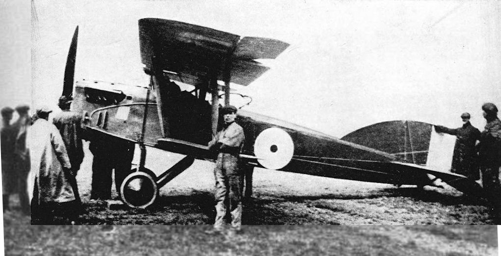
F.B.24 experimental fighter-bomber with Hispano Suiza engine. The first F.B.24 variant to appear, with large fin and conventional fuselage/wing arrangement.
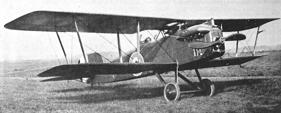
The Vickers F.B.24C with 275hp Lorraine-Dietrich 8Bd V-8 engine with frontal radiator and modified fim and rudder. It is difficult to see how exactly the pilot gained entry to his cockpit, let alone abandoned it in any emergency, with the centre section struts immediately fore and aft.
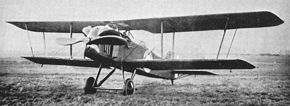
Vickers F.B.24C with side radiators.
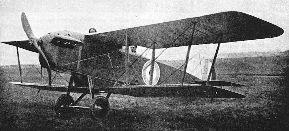
Vickers F.B.24E.
Vickers F.B.25
THE Vickers F.B.25 was a two-seat pusher biplane in the same category as the Royal Aircraft Factory N.E.1. It was similarly equipped with a small searchlight in the nose and was intended to carry a Crayford rocket gun for use against enemy airships.
The most remarkable feature of the F.B.25 was the side-by-side seating of its crew; the seats were slightly staggered so that the starboard was slightly in front of the port. The nacelle was thus unusually wide. Although it was mounted midway between the wings and therefore was high above the ground, it was fitted with a nose-wheel, obviously to minimise the risk of nosing over in a night landing.
The two-bay wings were of equal span and, in accordance with Vickers practice, the upper was made in two halves which met at a central trestle-shaped cabane structure. There was a centre-section in the lower wing, and the undercarriage was attached directly to it. The tail-booms converged in elevation to meet at the rear spar of the tailplane. The fin and rudder combined to form a circular surface which was symmetrical about the tailplane.
The Vickers F.B.25 was intended to have the 200 h.p. Hispano-Suiza engine, but the only power unit which could be made available for the aircraft was a 150 h.p. direct-drive Hispano-Suiza. Thus the F.B.25 suffered the fate of most of the other Vickers types of the war period, and its performance was adversely affected by the reduction of power.
The F.B.25’s career was short and undistinguished, for it crashed while undergoing its official tests at Martlesham Heath. The following extract from the official report indicates that the F.B.25 was not a satisfactory aircraft:
“The machine was extremely slack on all controls even with the engine on, but with it off it became very dangerous, the controls having practically no effect. The machine was almost unmanageable in a wind over 20 m.p.h., and it was owing to this that the machine crashed on test.”
SPECIFICATION
Manufacturers: Vickers Ltd. (Aviation Department), Imperial Court, Basil Street, Knightsbridge, London, S.W.
Power: 150 h.p. Hispano-Suiza.
Dimensions: Span: 41 ft 6 in. Length: 28 ft 1 in. Height: 10 ft 10 in. Chord: 6 ft 3 in. Gap: 6 ft. Stagger: nil. Dihedral: 3. Incidence: 3.
Areas: Wings: upper 250 sq ft, lower 250 sq ft, total 500 sq ft. Ailerons: each 14-25 sq ft, total 57 sq ft. Tailplane: 38-6 sq ft. Elevators: 29 sq ft. Fin: 9 sq ft. Rudder: 10-25 sq ft.
Weights and Performance: No. of Trial Report: M.124. Date of Trial Report: July, 1917. Weight empty: 1,608 lb. Military load: 200 lb. Crew: 360 lb. Fuel and oil: 286 lb. Loaded: 2,454 lb. Maximum speed at 5,000 ft: 86 m.p.h.; at 6,500 ft: 84-5 m.p.h.; at 10,000 ft: 76-5 m.p.h.; at 12,000 ft: 72 m.p.h. Climb to 1,000 ft: 1 min 35 sec; to 3,000 ft: 5 min 5 sec; to 6,000 ft: 11 min 55 sec; to 10,000 ft: 27 min 10 sec; to 12,000 ft: 44 min 5 sec. Service ceiling: 11,500 ft. Absolute ceiling: 13,500 ft. Endurance: 4 1/2 hours.
Armament: The armament for which the Vickers F.B.25 was designed was a Vickers Crayford rocket gun.

General arrangement drawings of the Vickers F.B.25.
Vickers F.B.26, Vampire
CLEARLY proclaiming its descent from the Vickers F.B.12 pusher scout, the Vickers F.B.26 appeared in May 1917. It was a two-bay biplane with wings of unequal span and chord, and was fitted with a 200 h.p. Hispano-Suiza engine.
The F.B.26 originally had its upper wing made in two halves which met on the aircraft centre-line in typical Vickers fashion. The nacelle was attached directly to the upper wing. Under the nacelle there was a centre-section to which the lower mainplanes were attached. The outer pair of interplane struts on either side were raked sharply outwards. As on the F.B.12 and F.B.25 the tail-booms converged in side elevation to meet at the rear spar of the tailplane. A plain vee undercarriage was fitted: the forward leg of each vee was attached to the lower longeron of the nacelle; the rear leg was attached to the front spar of the lower centre-section.
The radiator was at first installed as a plain flat vertical surface at the extreme rear of the nacelle, but this did not give adequate cooling. Two separate radiator blocks were next tried; one was fitted under the rear spar of each upper wing immediately above the engine. The final radiator installation consisted of twin radiators mounted on the sides of the nacelle; each element was below and in front of the engine.
By the time the side radiators were installed the design of the F.B.26 had undergone modification. A completely new wing structure was introduced: both upper and lower wings had wide centre-sections which spanned the distance between the inboard pairs of interplane struts, and only the outer portions of both wings were rigged with dihedral. The span of the lower ailerons was increased, and a new fin and rudder were fitted; the new surfaces were of higher aspect-ratio than those originally fitted.
In its first form the F.B.26 had been armed with two Lewis guns mounted side-by-side in the nose of the nacelle. The modified machine was fitted with the experimental Eeman triple mounting, which carried three Lewis guns. The F.B.26 was flown both with the guns relatively low down and with them raised above the upper longerons of the nacelle; in the latter case the nacelle was built up unusually high in front of the cockpit. The lower installation proved to be satisfactory (though the reloading of three separate Lewis guns in the heat of combat would almost certainly have proved to be something of a trial for the pilot); but the elevated installation was regarded as unwieldy and was abandoned. It must have interfered seriously with the pilot’s forward view.
The early F.B.26 was test-flown at Joyce Green by Harold Barnwell, who permitted Captain J. T. B. McCudden to fly it. (As is related in the history of the Vickers F.B.16, McCudden was at that time an instructor at Joyce Green.) He found that the F.B.26 “was very much the same as an F.E.8 to fly.” The type was also flown by Captain W. G. Barker (later Major Barker, V.C., D.S.O., M.C.), who thought well of it.
The modified F.B.26 with the lower Eeman gun-mounting was at one time fitted with flare brackets under the lower wing and a generator on the forward leg of the starboard undercarriage vee. The aircraft was clearly equipped for night-flying, and may have been the F.B.26 which was sent to No. 141 Squadron in 1918. The aircraft was not popular in the squadron: although it was fast it had poor climbing characteristics, and was unpleasant to spin, for its speed of rotation was very great. It is believed, however, that an F.B.26 was with No. 39 Squadron at North Weald in October, 1917, but it is uncertain whether this was the same aircraft that went to No. 141 Squadron.
In 1918 a new variant of the F.B.26 appeared. The Vickers F.B.26A was an armoured trench-fighter with a 230 h.p. Bentley B.R.2 rotary engine in place of the Hispano-Suiza of the original version; the airframe was that of the second F.B.26, B.1485. The nose of the nacelle was a little blunter and shorter, and the engine was mounted well forward in order to keep the centre of gravity in the correct place. The F.B.26A nacelle was therefore shorter overall than that of the F.B.26, and a cut-out had to be made in the upper centre-section to permit the engine to rotate. The disposition of the lower centre-section struts had to be altered, and the rear leg of each undercarriage vee was attached to the rear spar of the lower centresection instead of to the front spar as on the F.B.26.
The wings and tail unit of the F.B.26A were identical in form to those of the modified F.B.26.
By this time the Eeman triple gun-mounting had been abandoned, and the armament consisted of a pair of Lewis guns in the nose of the nacelle. The armour plate, which weighed 500 lb, was apparently fitted inside the nacelle structure, and the pusher arrangement of the aircraft enabled both pilot and engine to be protected by the armour.
By the time the Vickers F.B.26A appeared the official scheme for naming aeroplanes was in being. The name Vampire was given to the F.B.26 design: the F.B.26 with Hispano-Suiza engine was designated Vampire Mark I; the F.B.26A became the Vampire Mk. II.
The Vampire Mk. II was reported to be a good aeroplane with excellent manoeuvrability. Its performance was remarkably good for a pusher, and the pilot had a clear forward view for ground-strafing. But the Sopwith Salamander had been adopted as the standard trench-fighter, and the Vampire was abandoned.
SPECIFICATION
Manufacturers: Vickers Ltd. (Aviation Department), Imperial Court, Basil Street, Knightsbridge, London, S.W. The F.B.26s were built at Vickers’ Bexley Heath works.
Power: F.B.26: 200 h.p. Hispano-Suiza. F.B.26A: 230 h.p. Bentley B.R.2.
Dimensions: Span: upper 31 ft 6 in.; lower (original F.B.26) 29ft, (modified F.B.26 and F.B.26A) 27 ft 6 in. Length: (F.B.26) 23 ft 5 in., (F.B.26A) 22 ft 11 in. Height: 9 ft 5 in. Chord: upper 5 ft 6 in., lower 4 ft 6 in. Gap: (F.B.26) 4ft 3 in. (modified F.B.26 and F.B.26A) 4ft 4 1/4 in. Stagger: 1 ft 6 in. Dihedral: (F.B.26) 3° 30', (modified F.B.26 and F.B.26A) 4°. Incidence: 2°. Span of tail: 12 ft 3 in. Airscrew diameter: (F.B.26A) 8 ft 9 in.
Areas: (modified F.B.26 and F.B.26A) Wings: upper 158 sq ft, lower 109 sq ft, total 267 sq ft. Ailerons: each upper 12 sq ft, each lower 6 sq ft, total 36 sq ft. Tailplane: 22 sq ft. Elevators: 16 sq ft. Fin: 6-4 sq ft. Rudder: 6-7 sq ft.
Weights (lb) and Performance:
Aircraft F.B.26 F.B.26A
No. of Trial Report M.127 -
Date of Trial Report July, 1917 -
Weight empty 1,470 1,870
Military load 80 230
Pilot 180 180
Fuel and oil 300 158
Weight loaded 2,030 2,438
Maximum speed (m.p.h.) at
ground level - 121
5,000 ft 121 118
10,000 ft 117 115
m. s. m. s.
Climb to
5,000 ft 4 20 5 00
6,500 ft 6 00 - -
10,000 ft 9 54 12 00
15,000 ft 18 56 - -
Ceiling: service (feet) 20,500 -
absolute (feet) 22,500 19,000
Endurance (hours) 3 2
Tankage: F.B.26. Petrol: main tank 31 gallons, gravity tank 2 gallons, total 33 gallons. F.B.26A. Petrol: 29 gallons. Oil: 6 gallons.
Armament: The F.B.26 (Vampire I) had twin Lewis machine-guns in the nose of the nacelle firing forward; later, three Lewis guns on an Eeman triple mounting were fitted. The F.B.26A (Vampire II) had twin Lewis guns in the nose of the nacelle.
Service Use: One Vickers F.B.26 was sent to a Home Defence unit in 1918. It is believed that the type was flown by Nos. 39 and 141 Squadrons, R.F.C.
Serial Numbers: B.1484-B.1489, ordered under Contract No. A.S.27055/1. At least three (B.1484-B.1486) were built; B.1485 became the Vampire II.
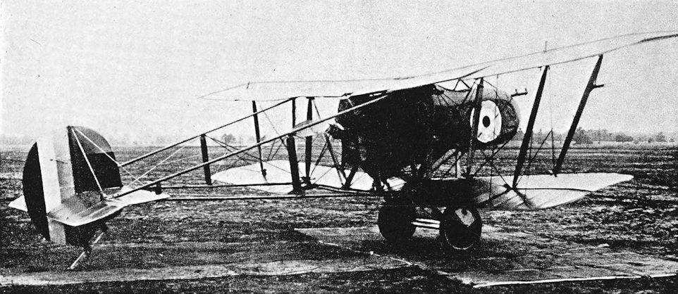
The Vickers F.B.26 in its original form, with a flat radiator behind the engine. The dihedral of the upper wings is from the roots.
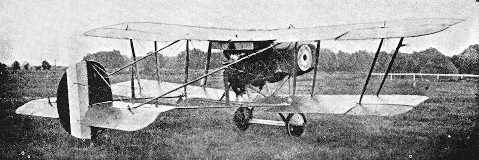
Vickers F.B.26 with modified radiator arrangement.
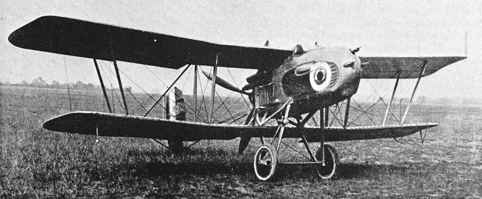
Modified F.B.26 with new wings incorporating wide centre-sections. The aircraft, B.1484, has an Eeman triple gun-mounting, an enlarged fin and rudder, and side radiators.
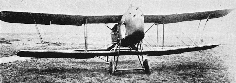
Modified F.B.26 with raised Eeman gun-mounting.
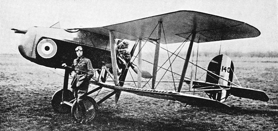
Vickers F.B.26A, Vampire Mk. II, B.1485 with armoured nacelle, modified undercarriage, and B.R.2 engine.
Vickers F.B.27, Vimy
IN the history of the Handley Page O/400 mention has been made of the events underlying the official decision to order night-bombers in quantity and the orders for the prototypes of new heavy bombers. Handley Page Ltd. and Vickers Ltd. each received an order for three experimental machines.
These orders were placed soon after the meeting of the Air Board which was held on July 30th, 1917, and work began on the Vickers design almost immediately. Responsibility for the new design was undertaken by Rex K. Pierson, who sketched his first ideas for the bomber during a discussion of the project with Major J. C. Buchanan at the Air Board. The aircraft which emerged with the designation Vickers F.B.27 bore a general resemblance to those rough sketches.
The design and construction of the first F.B.27 was accomplished in a little under five months, a remarkable achievement when the aircraft concerned was one so large. The F.B.27 was in fact largest aeroplane designed by Vickers Ltd. up to that time. It bore a family resemblance to the F.B.8 of 1915, but was almost twice as large.
The first F.B.27, which was numbered B.9952, was completed in November 1917, and was flown for the first time on the 30th of that month by Captain Gordon Bell. It was a three-bay biplane with wings of equal span, powered by two 200 h.p. Hispano-Suiza engines which were mounted mid-way between the wings. Each engine was enclosed in a wide nacelle, and each had a flat frontal radiator; the exhaust manifolds had tall slender stack pipes which passed through the upper wing in order to exhaust above it. These upright pipes were later removed.
The basic structure was conventional but, in keeping with Vickers practice, use was made of steel tubing in the fuselage: the forward portion was made wholly of steel tubing; behind the rear centre-section struts McGruer hollow spars were used. There was a gunner’s cockpit in the extreme nose and another behind the wings.
The mainplanes were made in three parts. The centre-sections spanned the distance between the engines, and only the outboard portions had dihedral. Horn-balanced ailerons were fitted to upper and lower wings.
The tail-unit was a biplane structure incorporating twin balanced rudders; there was no fixed fin surface. The elevators of B.9952 were horn-balanced but were later replaced by plain elevators, and new tailplanes were fitted.
In January 1918, the F.B.27 was flown to Martlesham Heath to undergo official trials, and created something of a sensation by lifting a greater load than the considerably more powerful Handley Page O/400.
At about this time the second F.B.27, B.9953, was completed. This machine had two 260 h.p. Sunbeam Maori engines, and was fitted with wings and ailerons of different shape from those of B.9952. The mainplanes had square extremities; and the ailerons, which were flush with the wing-tips, were inversely tapered and had no horn-balances. This F.B.27 was not extensively tested because it crashed on an early flight.
The third prototype, B.9954, was fitted with two 260 h.p. Fiat A-12 engines, and was modified in some particulars: it was, in fact, up to production standard. The nose of the fuselage was slightly altered and the extent of the plywood covering was increased. A revised fuel system, incorporating gravity tanks in the upper centre-section, was installed. The engines had flat frontal radiators, and could be distinguished by their single exhaust manifolds along the starboard side of each nacelle.
The third F.B.27 crashed soon after its arrival at Martlesham. It had been loaded with live bombs for test purposes: they exploded, wrecked the aircraft and killed the pilot. However, the performance of the Fiat-powered version proved to be good, and the F.B.27 was ordered in quantities.
The first prototype B.9952 was later fitted with two 260 h.p. Salmson water-cooled radial engines. This version of the design was not developed further, however. By this time an official system of nomenclature for aircraft had been devised, and the name Vimy was bestowed upon the Vickers bomber. Even official documents conflict with each other over the allocation of Mark numbers, but the generally accepted system regards the first prototype as Vimy Mk. I, the Maori-powered machine as Vimy Mk. II, and the Fiat version as Vimy Mk. III. However, Technical Department Instruction No. 538A, dated January, 1919, lists Mks. I and II as the Maori and Fiat versions respectively, and gives the Mk. Ill designation to a Vimy powered by 230 h.p. B.H.P. engines. Production of the B.H.P.-powered Vimy was envisaged on a considerable scale, but it is doubtful whether any machines were completed with those engines.
The first production version of the Vimy was the Fiat-powered machine, which was earmarked for service as an anti-submarine patrol aircraft. There are indications that it may have been intended to adapt the Vimy to be a torpedo-bomber. The Armistice prevented the issue of any Vimys to coastal units, however.
The Vimy was ordered in large numbers: the first contract for 150 machines was given to Vickers Ltd. on March 26th, 1918, and by mid-September more than 900 had been ordered. It is of interest to note that, where types of engines were specified in the contracts, only the Fiat, B.H.P. and Liberty were mentioned. America was interested in the Vimy and had asked for an examination of the possibility of fitting two Liberty engines in the airframe. A trial installation was made, but the machine was destroyed by fire during erection at Joyce Green. The R.A.F. also asked for a Liberty-powered version, and a Vimy with twin Liberty engines was ultimately tested at Joyce Green. Doubtless the desire to use the Liberty engine was occasioned by the shortage of Rolls-Royce engines (for the Eagle would seem to have been a natural choice for the Vimy) and by the expectation of deliveries of Liberties.
That expectation was only partly realised, however, for deliveries of the American engine to Britain ceased in the summer of 1918. The Vimy then appeared in what was to be its best-known form, with two Rolls-Royce Eagle VIIIs, and the great majority of production machines had these engines. Official records agree that the Eagle-powered Vimy was the Mark IV. It seems that the first Vimy to have Eagle engines was F.9569. The engine nacelles were generally similar to those of the Fiat version, but had exhaust pipes along each side. Modified rudders with enlarged balance areas were fitted to F.9569, but production Vimys Mk. IV were fitted with fin surfaces in front of the rudders, presumably to counteract the greater torque of the more powerful engines. Production Vimy IVs had modified engine nacelles with slightly more angular lines than those of F.9569.
The performance of the Vimy IV was excellent. It could carry a worthwhile bomb load and fuel for an endurance of eleven hours at a top speed of 98 m.p.h. at 5,000 feet. It was intended to equip units of the Independent Force with the Mk. IV Vimy, and one was sent straight from Martlesham to Nancy in October, 1918. This was the only Vimy to go to France, but it arrived too late to see operational service before the Armistice and was returned to Martlesham to complete its trials.
After the Armistice production of the Vimy was reduced, but it was adopted for service use and remained in service for many years, both at home and overseas.
Despite its unspectacular Service career, the Vimy achieved immortality by its performances in long-distance flights immediately after the war. In a modified Vimy IV, Captain John Alcock and Arthur Whitten Brown made the first non-stop aerial crossing of the Atlantic. Their Vimy carried 865 gallons of petrol and 50 of oil. Take-off was at 4.28 p.m. (G.M.T.) on June 14th, 1919, at Munday’s Pond, near St. Johns, Newfoundland: at 9.25 a.m. (G.M.T.) on June 15th, the Vimy landed at Glifden in Ireland with fuel for another 800 miles flight still in its tanks.
A Vimy IV also made the first flight from Britain to Australia. Flown by Captain Ross Smith with his brother Keith Smith as navigator, and Sergeants Bennett and Shiers as mechanics, the Vimy left Hounslow on November 12th, 1919. After a remarkable series of adventures and hardships, the machine reached Port Darwin, over 11,000 miles away, at 3 p.m. on December 10th.
The Vimy was again chosen for the flight to Cape Town made by Wing Commander H. A. van Ryneveld, D.S.O., M.C., and Flight Lieutenant C. J. Quintin Brand, D.S.O., M.C., D.F.C. With two mechanics they left Brooklands on February 4th, 1920, but a night forced landing 80 miles from Wadi Haifa wrecked the Vimy, which had been named Silver Queen. A second Vimy, powered by the engines of the first, was obtained; it left Cairo on February 22nd. Silver Queen II was wrecked at Bulawayo, and the flight was completed in a D.H.9 on March 20th, 1920.
In the post-war period the Vimys in R.A.F. service were fitted with various types of engine, and were widely used. The Vimy ended its Service career as a parachute trainer. A passenger-carrying conversion known as the Vimy Commercial did much good work in its own right, and was in turn developed into the Vickers Vernon troop-carrier.
SPECIFICATION
Manufacturers: Vickers Ltd. (Aviation Department), Imperial Court, Basil Street, Knightsbridge, London, S.W. (Prototypes built at Bexley; production undertaken at Crayford and Weybridge works.)
Other Contractors: Clayton & Shuttleworth, Ltd., Lincoln; Morgan & Co., Leighton Buzzard; The Royal Aircraft Establishment, Farnborough, Hants; The Westland Aircraft Works, Yeovil, Somerset. Production was also to have been undertaken by Boulton & Paul, Ltd., Riverside, Norwich, and by Ransomes, Sims & Jefferies, Ipswich, but the contracts placed with those two firms were cancelled before the Armistice.
Power: Two 200 h.p. Hispano-Suiza; two 260 h.p. Sunbeam Maori; two 260 h.p. Fiat A-12; two 300 h.p. Fiat A-12bis; two 230 h.p. B.H.P.; two 360 h.p. Rolls-Royce Eagle VIII; two 260 h.p. Salmson; two 400 h.p. Liberty.
Dimensions: Span: 67 ft 2 in. (68 ft 4 in. with Maori engines). Length: 43 ft 6 1/2 in. Height: 15 ft 3 in. Chord: 10 ft 6 in. Gap: 10 ft. Stagger: nil. Dihedral: originally 1° on Hispano-Suiza version; 3° on production versions. Incidence: 3° 30'. Span of tail: 16 ft. Airscrew diameter: Hispano-Suiza, 9 ft 3 in.; Fiat A-12bis, 9 ft 5 in.; Eagle, 10 ft 6 in.
Areas: Wings: (Hispano-Suiza version) upper 684 sq ft, lower 642 sq ft, total 1,326 sq ft. (Maori) upper 709 sq ft, lower 667 sq ft, total 1,376 sq ft. (All other versions) upper 686 sq ft, lower 644 sq ft, total 1,330 sq ft. Ailerons: each 60-5 sq ft, total 242 sq ft. (Maori version) each 58-75 sq ft, total 235 sq ft. Tailplanes: (Hispano-Suiza) originally 88 sq ft, later 114-5 sq ft. (Other versions) 114-5 sq ft. Elevators: (Hispano-Suiza) originally 74 sq ft, later 63 sq ft. (Other versions) 63 sq ft. Fins (Rolls-Royce version only) two of 13-5 sq ft each.: Rudders: two of 10-75 sq ft each.
Tankage: Hispano-Suiza engines: petrol 91 gallons; oil 14 gallons. Fiat engines: petrol 170 gallons; oil 17 gallons. Eagle engines: petrol 452 gallons; oil 18 gallons.
Armament: The bomb-load could consist of eighteen 112-lb and two 230-lb bombs, carried in racks under the fuselage and lower centre-section. One Lewis machine-gun on Scarff ring-mounting on cockpit in nose; a second Lewis gun was carried on a Scarff mounting on cockpit aft of wings.
Serial Numbers:
Serial Nos. Contractor Contract No. Engine(s) specified in contract
B.9952-B.9954 Vickers, Bexley A.S.22689/1/1917 -
F.701-F.850 Vickers, Crayford 35A/532/C.4i2 Fiat, B.H.P. or Liberty
F.2915-F.2934 R.A.E. 35A/1029/C.834 Fiat
F.2996-F.3095 Clayton & Shuttleworth 35A/1030/C.835 See Note 1
F.3146-F.3195 Morgan & Co. 35A/1032/C.837 B.H.P.
F.8596-F.8645 Vickers, Weybridge 35a/i257/C.h66 See Note 2
F.9146-F.9295 Vickers, Weybridge 35A/1784/C.1895 See Note 2
F.9569 Vickers 35A/3872/C.4532 Eagle VIII
H.651-H.670 R.A.E. 35a/2O57/C-2334 Fiat
H.4046-H.4195 Boulton & Paul (Contract cancelled on August 30th, 1918) 35A/2295/O-2592 -
H.5065-H.5139 Westland 35A/2388/2689 Liberty
H.9413-H.9512 Ransomes, Sims & Jefferies (Cancelled November 1st, 1918) 35A/2938/C-3353 -
J.251-J.300 Clayton & Shuttleworth 35A/2978/C.34h See Note 1
J.7438-J.7457 - - Eagle VIII
It is believed that H.5230, H.9924 and J.7702 were Vimys.
Note 1. Of the Vimys ordered from Clayton & Shuttleworth, 124 were to be fitted with B.H.P. engines, the remainder with Fiats.
Note 2. Of the Vimys built by Vickers at Weybridge, it was intended to fit ten with Fiat engines, the remainder with B.H.P.s.
Production and Allocation: Over 1,000 Vimys were ordered. The Royal Aircraft Establishment built two in 1918, and Westland built twenty-five in 1918-19. One was sent to the Independent Force in 1918, and on October 31st of that year the R.A.F. had three on charge: one with the Independent Force and two at experimental stations.
Costs:
Airframe without engines, instruments and guns £5,145 0s.
Engines:
Fiat A-12bis (each) £1,617 0s.
Eagle VIII (each) £1,622 10s.
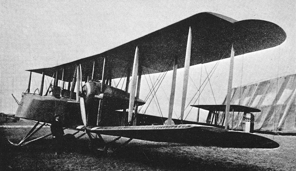
Vickers F.B.27, B9952 modified to have two 260 h.p. Salmson radial engines, and fitted with plain elevators.
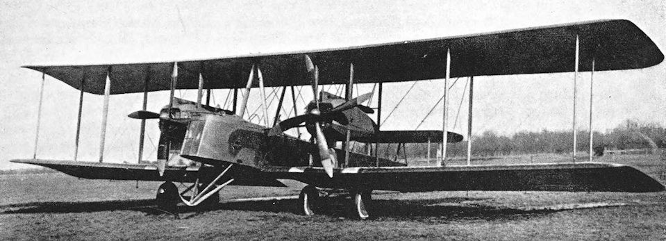
Vickers F.B.27, Vimy. The second prototype Vimy, B.9953, with two Sunbeam Maori engines, plain inversely-tapered ailerons, and modified wing-tips.
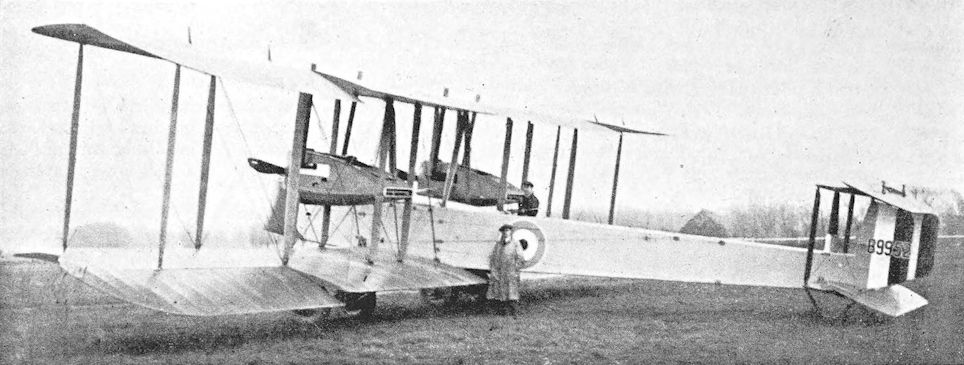
Vickers F.B.27. The first F.B.27, serial number B.9952, with two Hispano-Suiza engines, and horn-balanced elevators.
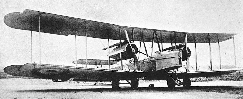
Vickers F.B.27, Vimy with two Fiat engines.
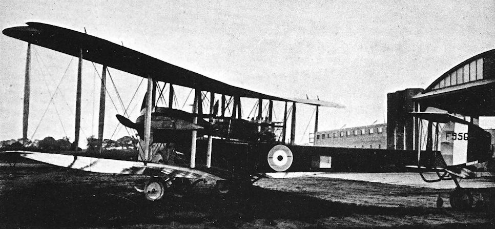
The first Vimy Mk. IV with two Rolls-Royce Eagle VIII engines and modified rudders.
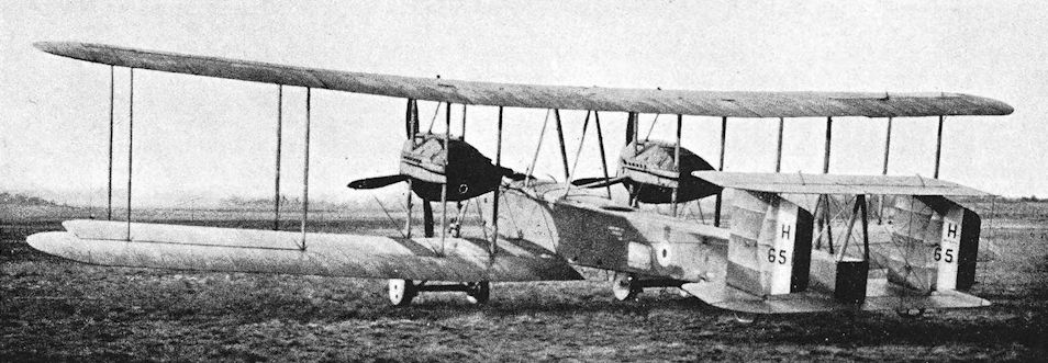
Production Vimy Mk. IV, serial number H.651, with fins added to tail-unit.
The first Vimy 'Mark III', H651, built by the Royal Aircraft Establishment with Fiat A.12bis engines. Although these engines returned a good performance, their unreliable delivery caused production of this version of the Vimy to be abandoned before completion.
The first Vimy 'Mark III', H651, built by the Royal Aircraft Establishment with Fiat A.12bis engines. Although these engines returned a good performance, their unreliable delivery caused production of this version of the Vimy to be abandoned before completion.
Wells Reo
THE Wells Aviation Company, Ltd., were one of the comparatively small aircraft manufacturing companies of the early days of the war. They later built various types of aircraft designed by other manufacturers until the end of hostilities. The company went into liquidation early in 1917, but the works then came under the aegis of Sir Samuel Waring and continued to produce aircraft.
In June, 1915, the Wells company produced the Reo, a single-seat biplane powered by a 35 h.p. Green engine. The flat side radiators and very long-chord fin and tailplane gave the machine a rather Germanic look. The two-bay wings were of equal span and were slightly staggered; the ailerons had pronounced inverse taper.
The most remarkable and unpractical feature of the Reo was its peculiar undercarriage. Each leg of each vee was bifurcated at its lower end, and the wheels ran in the forks thus formed. The upper ends of the rear legs of the vees were not attached to the longerons in the conventional fashion; instead they were attached to what appeared to be a form of leaf spring.
SPECIFICATION
Manufacturers: The Wells Aviation Co., Ltd., 10a Elystan Street, Chelsea, London.
Power: 35 h.p. Green.
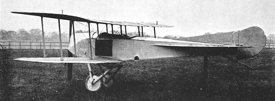
Wells Reo.
Westland N.1B Scout Seaplane
FOR about two years after its founding in April, 1915, the Westland Aircraft Works produced aircraft for the Admiralty. Short 184s, Short 166 seaplanes, Sopwith 1 1.2-Strutters and D.H.4s were built under the management of R. A. Bruce, who had been released by the Admiralty from his official duties as overseer at the Sopwith works, Kingston-on-Thames.
In 1917 Mr Bruce and his assistant A. Davenport began the design of a single-seat fighter seaplane intended for use from ships and capable of carrying two 65-lb bombs. Presumably the aim was to produce a replacement for the Sopwith Baby. The Westland scout seaplane fell within the Admiralty category N.1B.
Two machines, numbered N.16 and N.17, were built; both were powered by the 150 h.p. B.R.1 rotary engine and differed from each other in detail. The Westland seaplane was a simple two-bay biplane of conventional structure. The wings were arranged to fold backwards to conserve space on board ship, and the mainplanes of N.16 were fitted with trailing-edge flaps of the camber-changing type. These flaps were generally similar to the Fairey Patent Camber Gear and the variable-camber device of the Handley Page R/200.
The fuselage was deep, and at the stern-post the bottom longerons were still well below the bottom of the rudder. Two 65-lb bombs could be carried in external racks under the fuselage, and the pilot had two machine-guns: a fixed Vickers gun was mounted on top of the fuselage, and there was a Lewis gun above the centre-section. The Vickers gun of N.16 was enclosed in a fairing, but on N.17 the gun was exposed. A hole was cut in the centre-section to improve the pilot’s upward view.
The undercarriage of N.16 consisted of two Sopwith-built main floats and a sizeable tail-float on which was mounted a water rudder. The main-floats were simple wooden pontoons typical of the period.
In its best-known form the second machine, N.17, had long main-floats which had been designed and built by Westland themselves. These floats curved upwards slightly towards the stern, and were long enough to keep the aircraft’s tail out of the water without the use of a tail-float. N. 17 was also flown at the Isle of Grain with Sopwith floats and a tail-float identical to that ofN.16: the tail-float ofN.17 was attached directly to the bottom longerons, whereas that of the first machine was mounted on short struts.
Both machines could be fitted with wheels under the floats for take-off from a ship’s deck: these wheels were dropped after take-off.
The Westland seaplanes were tested by Commander Seddon at the Isle of Grain in October, 1917, and proved to have a good performance. By that time, however, it had been shown that the Sopwith Pup landplane could be flown successfully from ships. The Pups did not need lengthy flight decks, nor did they have to be hoisted out before take-off, and they were immediately available. Moreover, the faster Sopwith 2F.1 Camel was in prospect and capable of emulating the Pup’s ability to take off from small platforms. The Westland scout seaplanes were therefore shelved.
SPECIFICATION
Manufacturers: The Westland Aircraft Works, Yeovil, Somerset.
Power: 150 h.p. Bentley B.R.1.
Dimensions: Span: 31 ft 3 1/2 in. Length: 25 ft 5 1/2 in. Height: 11 ft 2 in. Chord: 5 ft. Gap: 5 ft. Dihedral: 2° 30'. Incidence: 1°. Span of tail: 11 ft. Distance between float centres: 7 ft 6 in. Airscrew diameter: 2,650 mm (8 ft 8-33 in.).
Areas: Wings: 278 sq ft. Ailerons: each 9-9 sq ft, total 39-6 sq ft. Tailplane: 24-5 sq ft. Elevators: 17-5 sq ft. Fin: 6-8 sq ft. Rudder: 7-5 sq ft.
Weights (lb) and Performance:
Aircraft N.17 with Sopwith Baby type floats N. 17 with Westland floats
No. of Trial Report - -
Date of Trial Report October 26th, 1917 October 29th, 1917
Type of airscrew used on trial A.D.664 A.D.664
Weight empty 1,504 1,513
Military load 53 53
Pilot 180 180
Fuel and oil 241 241
Weight loaded 1,978 1,987
Maximum speed (m.p.h.) at
1,800 ft 107-5 0
2,050 ft 0 107
3,750 ft 108-5 0
5,550 ft 107 0
6,000 ft 0 100
7,580 ft 0 85
8,900 ft 93 0
9,480 ft 0 83
m. s. m. s.
Climb to
2,000 ft 3 50 3 10
6,000 ft 13 25 11 40
10,000 ft 28 40 29 45
Service ceiling (feet) 12,700 10,400
Endurance (hours) 2 3/4 2 3/4
Tankage: Petrol: 31-1 gallons. Oil: 5 gallons.
Armament: One fixed, forward-firing Vickers machine-gun mounted centrally on top of the fuselage, and synchronised to fire through the airscrew; 250 rounds of ammunition were carried for this gun. One Lewis machinegun was fitted on a mounting above the centre-section. Two 65-lb bombs could be carried in racks under the fuselage.
Serial Numbers: N.16-N.17, built under Contract No. C.P.136919/16.

Westland N.1B Scout Seaplane. The first machine, serial number N.16, with Sopwith-type floats, variable-camber gear, and cowled Vickers gun.

The second Westland N.1B, serial number N.17, with long Westland floats and exposed Vickers gun.

Westland N.1B Scout Seaplane, N.17 with Sopwith-type floats and tail-float attached directly to lower longerons.
Westland Wagtail
THE dainty little Wagtail was a single-seat fighter intended to operate at high altitude. Work on the design began in 1917, and the machine was designed around the new A.B.C. Wasp I radial engine of 170 h.p.
The first Wagtail appeared in 1918. It was a tiny equal-span biplane with fine lines and typical of its period as far as construction was concerned. The single-bay wings were slightly staggered, and originally the upper and lower wings were rigged with equal dihedral. The upper centre-section was fairly wide, and had a hole cut in it to improve the pilot’s upward view. The tail-unit was completely conventional, and the undercarriage was a simple vee structure. Sopwith practice was reflected in the use of a divided axle and independent springing (by means of the usual rubber cord) for each wheel.
The Wagtail was as manoeuvrable and manageable as it looked. On its first test flight, the test pilot (Captain Alexander) was so pleased with the little fighter’s flying qualities that he looped it.
The aircraft underwent some slight but noticeable modification. The rigging of the wings was altered: the upper wings were given five degrees of dihedral whilst the lower mainplanes were quite flat. This brought the centre-section closer to the fuselage and, in order to preserve the pilot’s forward and upward view, the size of the aperture in the centre-section was greatly increased and the entire trailing portion was removed.
A very practical feature of the Wagtail was the installation of the two Vickers guns where their breech mechanisms lay on either side of the cockpit: the pilot was therefore able to reach his guns easily when it was necessary to clear stoppages. In view of the Wagtail’s designed function as a high-altitude fighter oxygen equipment was installed.
Like the B.A.T. Bantam, the Wagtail suffered from the caprices of its A.B.C. Wasp engine, and the Armistice stopped development of the type. In the post-war years a Wagtail was experimentally fitted with an Armstrong Siddeley Lynx engine, presumably to air-test the power-unit. This aircraft had a shorter nose and a strengthened undercarriage.
SPECIFICATION
Manufacturers: The Westland Aircraft Works, Yeovil, Somerset.
Power: 170 h.p. A.B.C. Wasp I.
Dimensions: Span: 23 ft 2 in. Length: 18 ft 11 in. Height: 8 ft. Chord: 4 ft 6 in. Gap: originally constant at 4 ft 6 in.; later reduced to 4 ft at centre-section, 4 ft 6 in. at interplane struts. Stagger: 1 ft 6 in. Dihedral: originally 2° 30' on both mainplanes; later 5° on upper mainplane, nil on lower. Incidence: 2°. Span of tail: originally 9 ft, later reduced to 7 ft 10 3/4 in. Wheel track: 4 ft 8 in. Airscrew diameter: 2,590 mm (8 ft 6 in.).
Areas: Wings: 190 sq ft. Ailerons: each 6 sq ft, total 24 sq ft. Tailplane: originally 18-6 sq ft, later 15-5 sq ft. Elevators: originally 12-8 sq ft, later 9-5 sq ft. Fin: originally 3 sq ft, later 2-1 sq ft. Rudder: originally 3-3 sq ft, later 4-4 sq ft.
Weights: Empty: 746 lb. Military load: 185 lb. Pilot: 180 lb. Fuel and oil: 219 lb. Loaded: 1,330 lb.
Performance: Maximum speed at 10,000 ft: 125 m.p.h. Climb to 5,000 ft: 3 min 30 sec; to 10,000 ft: 7 min 30 sec; to 17,000 ft: 17 min. Endurance: 2 1/2 hours.
Tankage: Petrol: 26 gallons. Oil: 3 gallons.
Armament: Two fixed, forward-firing Vickers machine-guns mounted above the fuselage and synchronised to fire through the airscrew. Ammunition: 1,000 rounds. The original design envisaged the use of a Lewis gun mounted above the centre-section.
Production: Five Wagtails were built.
Serial Numbers: C.4291-C.4295, ordered under Contract No. 41838/1/17.
Westland Weasel
BUT for the Armistice and the unreliability of the A.B.C. Dragonfly engine, the Westland Weasel would have been competitive with the Austin Greyhound and Bristol Badger as a replacement for the Bristol F.2B.
The Weasel appeared late in 1918, bearing a strong family resemblance to the little Wagtail. It was a two-bay equal-span biplane with a flat lower wing and pronounced dihedral on the upper. The pilot sat under the rear spar of the centre-section, in which a large cut-out gave him an upward view. Twin Vickers guns, mounted in troughs on top of the fuselage, were fitted; and the deep rear cockpit gave the observer comfortable use of his Scarff ring-mounting. Oxygen was carried, and electrical heating equipment was provided.
The construction of the airframe was typical of the period: plywood and fabric covered a wire-braced wooden structure. The incidence of the tailplane could be altered from the cockpit.
The Weasel handled well and was quite a promising aircraft. Owing to the failure of the Dragonfly engine production of the Weasel was not considered, but the prototypes were later used as flying test-beds at the R.A.E., and provided a considerable amount of useful information. The Weasel F.2914, originally powered by a Dragonfly, was later fitted with a 350 h.p. Armstrong Siddeley Jaguar II (engine No. A.S. 21/26502). All armament was removed, and an enlarged fin and horn-balanced rudder were fitted.
The 400 h.p. Bristol Jupiter II was installed in J.6577, which also had an enlarged fin and balanced rudder. This, the last Weasel, also had horn-balanced ailerons and retained its armament. The Jupiter and Jaguar-powered Weasels were still flying in 1923.
SPECIFICATION
Manufacturers: The Westland Aircraft Works, Yeovil, Somerset.
Power: 320 h.p. A.B.C. Dragonfly I. Experimental installations of the 350 h.p. Armstrong Siddeley Jaguar II and the 400 h.p. Bristol Jupiter II were made after the war.
Dimensions: Span: 35 ft 6 in. Length: 24 ft 10 in. Height: 10 ft 1 in. Chord: 5 ft 6 in. Stagger: 1 ft 11 in. Dihedral: upper 5°, lower nil. Incidence: 2°.
Areas: Wings: 368 sq ft.
Weights and Performance: No. of Trial Report: M.264. Date of Trial Report: September, 1919. Type of airscrew used on trial: A.B.8973. Weight empty: 1,867 lb. Military load: 334 lb. Crew: 360 lb. Fuel and oil: 510 lb. Loaded: 3,071 lb. Maximum speed at 6,500 ft: 130-5 m.p.h.; at 10,000 ft: 129-5 m.p.h.; at 15,000 ft: 122-5 m.p.h. Climb to 6,500 ft: 5 min 50 sec; to 10,000 ft: 10 min; to 15,000 ft: 19 min. Service ceiling: 20,700 ft.
Armament: Two fixed, forward-firing Vickers machine-guns on top of the fuselage in front of the pilot’s cockpit; one Lewis machine-gun on Scarff ring-mounting on rear cockpit.
Production: Four Weasels were built.
Serial Numbers: F.2912-F.2914. J.6577.

Westland Weasel with A.B.C. Dragonfly engine.
White and Thompson No. 3 Flying-boat
NORMAN A. THOMPSON was a young Cambridge graduate who was trained as an electrical engineer, but who decided in 1908 to devote his life to aviation. His enthusiasm was fired by Mr (later Dr) F. W. Lanchester’s book on Aerodynamics, and in 1909 he secured the collaboration of Lanchester in the design of aeroplanes. By this time Norman Thompson had gone into partnership with Douglas White, a man of considerable means, who provided the money needed to finance their aeronautical experiments.
The first aircraft to be produced by the partnership was a remarkable biplane with wings covered with 23-gauge sheet aluminium and powered by two 50 h.p. Gnome engines. This machine was not successful, but the experiments almost exhausted the money that had been set aside for the purpose, and it was decided to undertake aircraft construction on a commercial basis. It was not until June 1912, however, that the White and Thompson Co., Ltd., was registered as a private company.
A pusher biplane with a 120 h.p. A.B.C. motor was designed by Norman Thompson himself and was flown in 1913. Although this machine was damaged early in 1914, no attempt was made to rebuild it, because the firm had secured the exclusive British agency for the Curtiss flying-boat and thereafter devoted most of their attention to that form of aircraft.
The Daily Mail “Round Britain” contest for seaplanes appeared to offer the firm a good opportunity to establish the capabilities of flying-boats. A bold step was taken: two flying boats of different design were entered for the race, one a single-engined machine powered by a 120 h.p. Beardmore engine, the other a larger twin-engined type with two 90 h.p. Curtiss OX engines. The single-engined White and Thompson flying-boat bore a general resemblance to the Curtiss machine, but was in fact designed throughout by the British company. The 24-foot hull was made by S. E. Saunders. Two skins of copper-sewn mahogany were applied to a framework of ash and spruce to form a structure which was light yet strong. The square-cut wings had two bays of bracing with extensions on the upper mainplanes, and a large vertical fin surface was mounted centrally above the centre-section. The long, low aspect-ratio fin was surmounted by the tailplane and elevator assembly, and a horn-balanced rudder was fitted. Dual control was provided.
The White and Thompson boat was to have been flown in the race by Captain E. C. Bass, but the outbreak of war led to the cancellation of the contest. The single-engined machine was tested on August 9th, 1914, and was said to be satisfactory. It was bought by the Admiralty, and six further examples of the type were ordered.
These six were built and delivered, and were followed by at least two more. The “production” version was known as the White and Thompson No. 3 Flying-boat, and differed from the original in several respects. The hull shape remained similar, but there was a fairing behind the rear spar of the lower centresection, which was covered, whereas that of the original had been open. The wing-tips were slightly rounded, and the extensions of the upper wings were wire-braced from king-posts above the outer interplane struts. The single central fin surface which had been mounted above the centre-section of the Round Britain machine was replaced by two low aspect-ratio surfaces, one above each pair of inboard interplane struts.
In the tail-unit the fin area was slightly increased, and a secondary fin above the tailplane occupied the place of the balance area of the rudder of the original flying boat. A plain rudder was fitted, and a small beaching skid was placed under the extreme tail of the hull.
The standard engine was the 120 h.p. Beardmore, but one machine had a 150 h.p. Hispano-Suiza. Additional struts were fitted between the hull and the forward end of the engine bearers; for a time at least No. 1195, the first “production” machine did not have these struts, but most of the others did.
Test flying was done by E. C. Gordon England, and he delivered the first machine to the R.N.A.S. at Dover. Douglas White flew with him on the delivery flight.
The Service history of the type is obscure, but its makers claimed that the machines were “the first flying-boats to give a satisfactory account of themselves in service, and proved a very effective weapon directed against German submarines.”
SPECIFICATION
Manufacturers: White & Thompson, Ltd., Bognor Regis, Sussex.
Power: 120 h.p. Beardmore; 150 h.p. Hispano-Suiza.
Dimensions (original “Round Britain” machine): Span: upper 45ft, lower 34ft. Length: 27 ft 6 in. Chord: 5 ft 6 in. Gap: 5 ft 9 in. Stagger: nil. Dihedral: nil. Span of tail: 12 ft.
Areas (original): Wings: 400 sq ft. Tailplane: 30 sq ft. Elevators: 27 sq ft. Rudder: 16 sq ft.
Weights (original): Empty: 1,600 lb. Loaded: 2,400 lb.
Performance (original): Maximum speed: 70 m.p.h. Endurance: 6 hours. Production: maximum speed: 85 m.p.h. Climb to 9,000 ft: 20 min.
Tankage (original): Petrol: 60 gallons.
Armament: One Lewis machine-gun on pillar-type mounting on port side of cockpit.
Service Use: R.N.A.S. Station, Dover.
Production: At least eight White & Thompson No. 3 Flying-boats were built.
Serial Numbers: 1195-1200, 3807-3808.

White & Thompson No. 3 Flying-boat. The first production machine, No. 1195.

White & Thompson No. 3 Flying-boat. No. 3807, with additional struts to the forward ends of the engine-bearers.
White and Thompson “Bognor Bloater”
SHORTLY after the outbreak of war, F. P. H. Beadle joined the White and Thompson company as chief designer. His first design for his new firm was a two-seat tractor biplane landplane which was remarkable for a fine wooden monocoque fuselage. The type appeared in 1915, and it has been claimed that it was the first aircraft in the world with a monocoque fuselage to go into production.
There may be justification for this claim, for a small batch was ordered by the Admiralty. When the machines were delivered to the R.N.A.S. they were nicknamed “Bognor Bloaters”, a name which coupled their place of origin to the allegedly scaly appearance of the fuselage with its copper stitching against the cedar planking.
The fuselage was a boat-built structure, in which diagonal planking of Saunders “Consuta” plywood was applied to formers and stringers. Great care was taken to ensure a good finish: the copper stitching was made flush with the surface, and the completed fuselage was varnished. The fuselages were built by Williams of Littlehampton. A 70 h.p. Renault engine was mounted in the nose, and had exhaust manifolds which ran downwards to exhaust under the lower wing.
It seems a pity that these fine fuselages were fitted with such unprepossessing flight organs. The two-bay wings were of unequal span, and were fitted with ailerons which projected behind the trailing edges of the mainplanes. Instead of conventional centre-section struts there were full-length interplane struts hard against the fuselage.
The tail surfaces were of simple design, and the undercarriage was a twin-skid affair reminiscent of that of the B.E.2. The undercarriage could be fitted with a claw brake which could be released on landing to drag in the ground and bring the aircraft to a standstill.
The test-flying of the Bognor Bloater was performed by E. G. Gordon England, and the first machine was flying in March, 1915. The type was also flown by Clifford Prodger, who had a good opinion of it, and it is recorded that he looped one of the Bloaters.
The Service function of this unwarlike aeroplane remains obscure, but there can be little doubt that it would have been used for training purposes.
SPECIFICATION
Manufacturers: White & Thompson, Ltd., Bognor Regis, Sussex.
Power: 70 h.p. Renault.
Service Use: R.N.A.S. Stations at Eastbourne, Great Yarmouth and Killingholme.
Production: Twelve were ordered and at least ten were built.
Serial Numbers: 1171-1182.
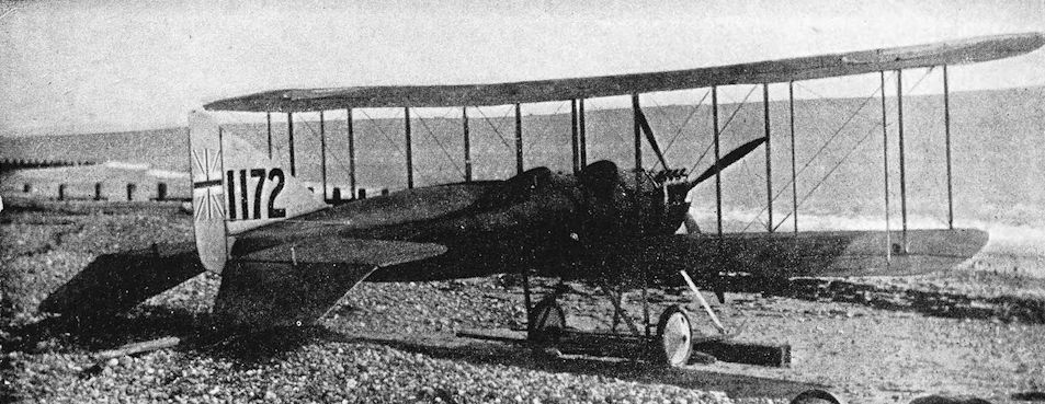
White & Thompson “Bognor Bloater”.
Whitehead Scout
THE Whitehead Aircraft Company were contractors for several types of aeroplane during the 1914-18 war; their principal product was the Sopwith Pup. In 1916 the company designed and built a singleseat scout which, like the standard Pup, was powered by an 80 h.p. Le Rhone rotary engine.
The Whitehead Scout was a single-bay, equal-span biplane which bore a resemblance to the Vickers E.S.2. The likeness lay chiefly in the fuselage, which was carefully faired out to a circular cross-section throughout its length and was of good aerodynamic form. The pilot’s forward and downward vision must have been obstructed by the fullness of the fairing on either side.
The wings were slightly staggered, and ailerons were fitted to upper and lower mainplanes. The centre-section was supported on two substantial N-struts, and aft of the rear spar it was cut away to improve the pilot’s view in an upward and forward direction. There can be little doubt, however, that the generally poor outlook from the cockpit would not make the Whitehead machine acceptable for Service use.
SPECIFICATION
Manufacturers: Whitehead Aircraft Co., Ltd., Townshend Road, Richmond.
Power: 80 h.p. Le Rhone.

Whitehead Scout.
Wight Pusher Seaplane
ON January ist, 1913, the well-known boat-building company of John Samuel White & Co., of East Cowes, opened an aviation department. The chief designer and manager of the new department was Howard T. Wright, one of Britain’s earliest successful aircraft designers. In view of the company’s long and distinguished connexion with marine craft it was only to be expected that their aircraft would be float seaplanes. The company’s products were named Wight aircraft, a name which represented not only the place of their manufacture but also a neat blending of the names of the company and their chief designer.
A series of single-engined pusher seaplanes were built before the outbreak of war, commencing with the machine which was shown at the Olympia Aero Show in February, 1913. This aircraft introduced two features which were to characterise all the Wight machines designed by Howard Wright: it had a peculiar aerofoil with double camber on the upper surface, and the floats of the undercarriage were so long that no tail-float was needed. The engine was a 160 h.p. Gnome rotary.
The Wight seaplane underwent development and modification throughout 1913. By the time of the 1914 Aero Show a new and enlarged machine had been built, and was exhibited at Olympia. The new Wight had five-bay wings and was powered by a 200 h.p. Salmson water-cooled radial engine. Two large radiator blocks were fitted to the sides of the nacelle just in front of the engine; the nacelle itself was mounted mid-way between the wings. The tailplane was mounted above the upper tail-booms, and there were two horn-balanced elevators. The long floats had three steps each and were made of plywood on an elm framework; each float was divided into six water-tight compartments.
The German government bought a Wight seaplane of the type exhibited, and the British Admiralty also placed contracts for similar machines. When these were built they incorporated a number of modifications.
The most important structural alteration was the introduction of folding wings: the mainplanes were hinged about the rear spar at the struts in line with the floats. The span of the upper wing was increased by several feet, and the extensions were braced by struts. The bracing system between the floats was modified and became more complex, and a new tail-unit was fitted. The tail-boom structure was strengthened and was deeper in side elevation; the tail-unit was a biplane structure, and two rectangular fins were introduced, one in front of each rudder. Enlarged radiators were mounted on the sides of the nacelle in front of the leading edge of the wings.
When the aircraft carrier Ark Royal left Sheerness for the Dardanelles on February 1st, 1915, among her complement of aircraft were two Wight pusher seaplanes. The Ark Royal arrived at Tenedos on February 17th, and her aircraft were put into use immediately; four flights were attempted that same day. Only one was successful, however. It was a reconnaissance of the enemy forts made by Flight Lieutenant G. R. Bromet and Flight Commander H. A. Williamson, flying a Wight pusher seaplane.
The Wights were not an unqualified success, however, for they could not be relied upon to take off from a choppy sea. They were used when conditions permitted, and on March 18th, 1915, Flight Lieutenant R. Whitehead and Lieutenant L. H. Strain flew a Wight over the Turkish forts of the Narrows defences to observe the fire of the ships of the Allied fleet in its unsuccessful and costly attempt to silence the enemy defences. Eight days later, a reconnaissance of the forts was made by Flight Lieutenant Bromet and Sub-Lieutenant W. Park in a Wight.
At the end of March, 1915, Ark Royal went to Mudros to take on a new Wight, but thereafter the pusher seaplane finds no mention in the chronicle of the war.
SPECIFICATION
Manufacturers: J. Samuel White & Co., East Cowes, Isle of Wight.
Power: 200 h.p. Salmson (Canton-Unne).
Dimensions: Span: upper 63 ft, lower 59 ft. Chord: 6 ft 6 in. Gap: 5 ft 7 in.
Areas: Wings: 735 sq ft.
Weights: Empty: 2,600 lb. Loaded: 3,500 lb.
Performance: Maximum speed: 72 m.p.h.
Service Use: Dardanelles: H.M.S. Ark Royal.
Production: At least eleven Wight pushers with the 200 h.p. Salmson were built for the Admiralty, and one was supplied to Germany.
Serial Numbers: 155: built under Contract No. C.P.40818/14. 171-177: built under Contract No. C.P.37385/14. (176 went to the Dardanelles in Ark Royal.) 893-895.

Wight Pusher Seaplane. The 200 h.p. pusher seaplane in its original form.

Wight Pusher Seaplane, No. 176, showing extended upper wings, revised float-bracing, and modified tail-unit.
Wight Seaplane, Admiralty Type 840
CONTEMPORARY with and directly comparable to the Short Type 184 seaplane was a large Wight tractor seaplane powered, like the Short, by the 225 h.p. Sunbeam engine. A contemporary reference indicates that the machine was designated the Wight R.R. by its makers, but to the Admiralty it was known as the Wight Seaplane Type 840. The number was, of course, the serial number of a typical machine of the first production batch.
The Wight 840 was a four-bay biplane with extensions on the upper wings. Single-acting ailerons were fitted to the upper wing only, and the mainplanes were arranged to fold. The aerofoil section had the double-camber upper surface favoured by Howard Wright.
The long slender fuselage terminated in a simple strut-braced tail-unit; a small king-post was provided under the fuselage to support the lift struts for the tailplane. The fin was a simple triangular surface, and later machines had a similar, though somewhat smaller, fin below the fuselage. There was no tail-float, for the main-floats were long enough to keep the tail high at all times; each float had three steps.
The Wight 840 was intended to be a torpedo-carrier, and crutches were fitted to the rear three inter-float ties. On the first few machines these ties were arched to accommodate the torpedo; but later, as was the case with the Short 184, straight ties were fitted and no torpedo was carried.
The Wight 840 was ordered in quantity, but Whites were unable to expand their aircraft department in view of their ship-building commitments. Contracts were therefore given to Beardmore and to the Portholme Aerodrome, Ltd.; all but three of the Wights built by the latter contractor were delivered in the form of spares.
The type was used at a number of R.N.A.S. seaplane stations but was never so successful nor so numerous as the Short 184. The last Wight 840 in the R.N.A.S. was still in service at Scapa Flow in 1917.
SPECIFICATION
Manufacturers: J. Samuel White & Co., East Cowes, Isle of Wight.
Other Contractors: William Beardmore & Co., Ltd., Dalmuir, Dumbartonshire. Portholme Aerodrome, Ltd., St. John’s St., Huntingdon.
Power: 225 h.p. Sunbeam
Dimensions: Span: 61 ft. Length: 41 ft.
Areas: Wings: 568 sq ft.
Weights: Empty: 3,408 lb. Loaded: 4,453 lb.
Performance: Maximum speed: 81 m.p.h. Maximum endurance: 7 hours.
Armament: One 14-inch (810-lb) torpedo, or an equivalent load of bombs.
Service Use: R.N.A.S. Seaplane Stations such as Felixstowe and Scapa Flow; R.N.A.S. Station, Gibraltar.
Serial Numbers: 831-840: built by White. 1300-1319: built by White. 1351-1354: built by White. 1400-1411: built by Beardmore. 8281-8292: ordered from Portholme Aerodrome; only 8281-8283 were delivered; the rest were delivered as spares. 9021-9028. 9029-9040.
Notes on Individual Machines: 838 was flown at Felixstowe, 1406 at Gibraltar.

Wight Seaplane, Admiralty Type 840.

A Landplane version of the Wight 840 also existed, of which only one example is believed to have been completed. A different fin and rudder were used, and the tailplane was mounted on the upper longerons.
Wight Twin
THE big Wight Twin was an aircraft of similar configuration to the Blackburn T.B., for it was a float seaplane with twin fuselages and twin tail-units. The Wight type was designed for a completely different purpose, however, and had nearly twice the power of the Blackburn.
The Wight Twin had its origin in a biplane of 117-ft span which was built in 1914 to the design of Howard T. Wright, perhaps to perform the same functions as the Handley Page O/100. This big Wight was a twin-fuselage landplane powered by two 200 h.p. Salmson radial engines. The crew were accommodated in a small central nacelle, and each undercarriage unit had four main and two small wheels, The five-bay wings were arranged to fold backwards. The biplane tail-unit was a peculiar structure which incorporated four rudders, of which the two outermost were horn-balanced.
The tail-unit was later modified. The balance areas were removed from the outer rudders and large fins were added; the area under the upper tailplane was left open in each fin, however. The lower elevator was removed but the two small inner rudders were retained. In this form the aircraft crashed, as the illustration shows.
The next development of the design was a large seaplane which appeared with the official serial number 187. Whether this was a different aircraft or merely the landplane rebuilt is uncertain, but it may be significant that the same gap appeared in each fin. The wing structure also appeared to be identical. In the seaplane, however, the central nacelle was not retained: instead, a cockpit was provided in each fuselage. Additional oblique struts were used in the centre-section bracing, and the engines were fitted with extension shafts. The undercarriage consisted of two long main-floats, one under each fuselage. There were no tail-floats, but a small float was fitted under each lower wing-tip.
The Wight No. 187 was armed with a large torpedo, and must have been one of the earliest torpedo-carriers to be built. The missile was slung under the lower centre-section.
In 1915, two further machines, numbered 1450 and 1451, were built; they were also designed to be torpedo-carriers. These were generally similar to No. 187, but had taller undercarriages and completely revised vertical tail surfaces. The biplane tail with four rudders was retained, and the Salmson engines again had extension shafts. Each float was of broad beam and had three steps.
The two Twins were completed in September 1915 and were tested in the autumn of that year. The type was not successful, however, for it was unable to take off with a torpedo and a full load of fuel. No. 1450 went to Felixstowe and No. 1451 to Calshot; trials continued at both stations and torpedo drops were made. The Wight Twin was underpowered, however, and was ultimately abandoned.
SPECIFICATION
Manufacturers: J. Samuel White & Co., East Cowes, Isle of Wight.
Power: Two 200 h.p. Salmson (Canton-Unne).
Dimensions: Span: 117 ft.
Armament: One 18-inch Mark IX torpedo of just over 1,000 lb.
Serial Numbers: 187, 1450, 1451.
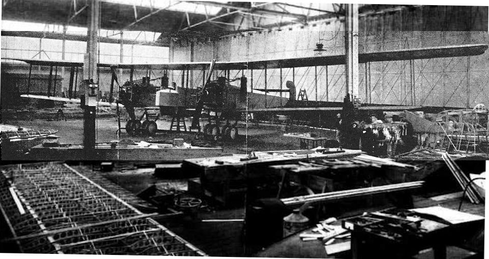
This view of the Wight Twin landplane provides a good impression of its great size as well as illustrating the central crew nacelle then included.
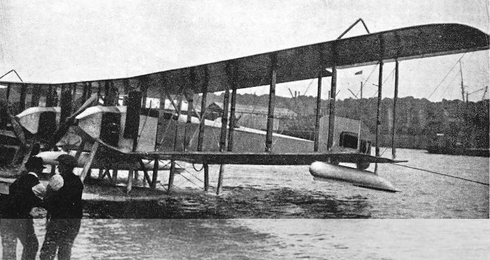
Wight twin-fuselage seaplane Admiralty type 187 with torpedo mounted under the lower centre-section. A modified version of the Twin landplane. Three were built but found unsuitable as torpedo carriers.
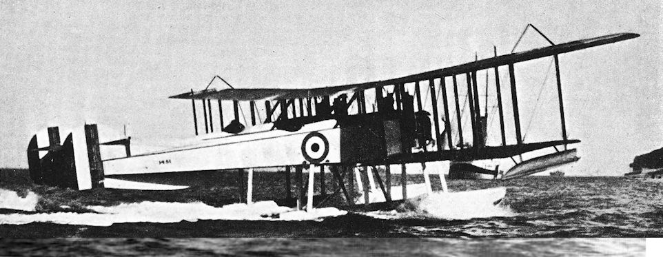
The third Wight Twin, No 1451, showing the two cockpits, set well aft of the wings; note also the wings of unequal span, with kingpost bracing to support the large upper wing overhang.
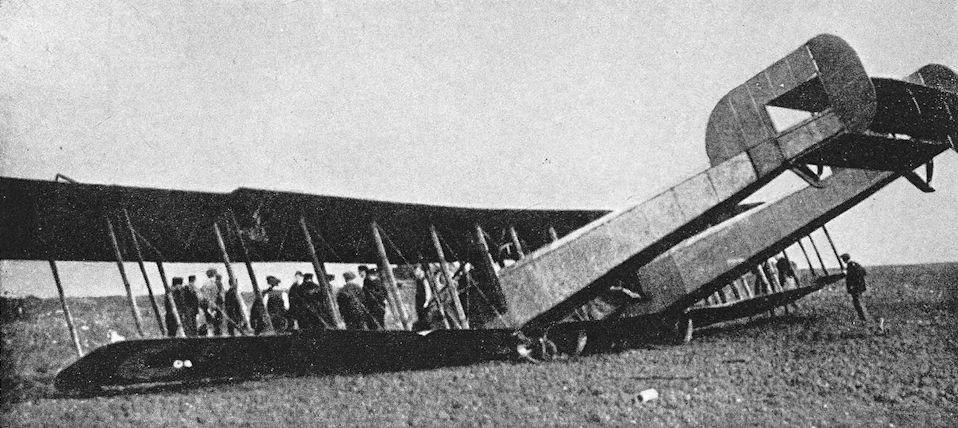
Wight Twin Landplane with modified tail-unit.
Wight Baby
THE Wight Baby of 1916 was a single-seat seaplane in the same category as the Sopwith Baby. The fact that it had folding wings indicates that it was probably intended for use from ships.
It was a spindly little aircraft powered by a 100 h.p. Gnome Monosoupape rotary engine which drove a four-bladed airscrew. The Wight Baby was structurally conventional: a wire-braced wooden structure was covered almost wholly with fabric. The upper wing was of noticeably greater chord and slightly greater span than the lower; and a seemingly primitive feature at that date was the use of single-acting ailerons, which were fitted to the upper wing only. Presumably it was intended thereby to minimise mechanical complication and to simplify wing folding. The aerofoil was of Howard Wright’s double-cambered section.
The vertical tail assembly was of characteristic outline, and recalled the shape of tail fitted to the big Wight Twin. The tailplane and elevators formed a simple rectangle; the tailplane was braced to the lower longerons by a single strut on either side. The two long shallow floats had three steps and were of sufficient length to hold the tail clear of the water. Each float had a small water-rudder.
In this form the Baby was flown at Felixstowe. It was later sent to the Isle of Grain for trials, by which time it had undergone a number of modifications. A new tail-unit was fitted: the area of the upper fin was increased, a new and taller rudder was fitted, the tailplane and elevators were given raked tips, and an extra strut was fitted to the rear spar of the tailplane. The lateral distance between the floats was increased appreciably, and ailerons of increased span were fitted.
The Wight Baby did not have a particularly good performance, and its abandonment became inevitable when successful flights from ships were made by such aircraft as the Sopwith Pup.
SPECIFICATION
Manufacturers: J. Samuel White & Co., East Cowes, Isle of Wight.
Power: 100 h.p. Gnome Monosoupape.
Dimensions: Span: 30 ft 8 in. (Folded, 11 ft 8 in.) Length: 26 ft 8 in. Height: 9 ft 1 in.
Areas: Wings: 297 sq ft.
Weights and Performance: Date of Trial Report: June 15th, 1917. Type of airscrew used on trial: L.5238. Weight empty: 1,277 lb. Military load: 130 lb. Pilot: 180 lb. Fuel and oil: 277 lb. Loaded: 1,864.1b. Maximum speed at 6,500 ft: 86-5 m.p.h. Climb to 2,000 ft: 4 min 50 sec; to 6,500 ft: 20 min 30 sec; to 10,000 ft: 48 min 30 sec. Service ceiling: 9,300 ft. Endurance: 2 1/2 hours.
Armament: No photograph shows evidence of any kind of armament, but the value of 130 lb quoted above as military load seems to indicate a possible load of two 65-lb bombs.
Production: Three prototypes were ordered under Contract No. C.P.110634/16.
Serial Numbers: 9097, 9098 and 9100.
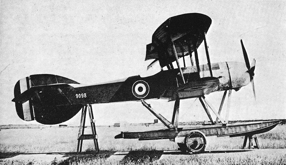
Wight Baby. Another view of the Baby at the Isle of Grain, showing the enlarged fin and rudder.
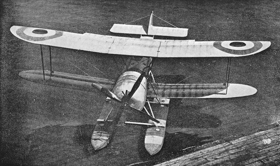
The Wight Baby in its original form with floats close together. This view shows the double-cambered aerofoil section favoured by Howard Wright.
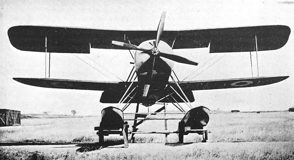
Wight Baby. This photograph, taken at the Isle of Grain, shows the Baby with widely-spaced floats, and the raked tips of the modified tailplane.
Wight Bomber
IN 1916, John Samuel White & Co. built a large single-engined biplane for the Admiralty. The new machine was a landplane and was intended to be used as a bomber. It was in the same category as the Short Bomber but, whereas the Short was a conversion of the Type 184 seaplane, the Wight Bomber was to provide the basis for a subsequent seaplane type.
The three-bay wings of the Wight Bomber were of unequal span; the extensions of the upper wings were braced from inverted vee king-posts above the outermost interplane struts. Single-acting ailerons were fitted to the upper wings only, and Howard Wright’s double-camber aerofoil section was again employed. The wings could be folded backwards to conserve hangar space.
Power was provided by a 275 h.p. Rolls-Royce engine of the type later known as the Eagle. The fuselage was a slender structure of conventional construction, and terminated in a typical Wight tail-unit of generous area. The undercarriage was a tall but simple vee structure. The bomb-load could consist of four 112-lb bombs in external racks under the lower wings.
The reasons for the non-adoption of the Wight Bomber are not far to seek. By the time the machine appeared the Short Bomber was in production by several contractors - production which was facilitated by the use of some Short 184 components. Moreover, the Handley Page O/100 was in prospect and the production of another single-engined bomber with only a quarter of the O/100’s bomb load would have been pointless. The Wight Bomber was, however, forthwith developed into a seaplane design.
SPECIFICATION
Manufacturers: J. Samuel White & Co., East Cowes, Isle of Wight.
Power: 275 h.p. Rolls-Royce.
Dimensions: Span: upper 65 ft 6 in., lower 55 ft. Chord: upper 7 ft, lower 5 ft 6 in. Gap: 5 ft 9 in. Span of tail: 15 ft.
Areas: Wings: upper 447 sq ft, lower 268 sq ft, total 715 sq ft. Ailerons: each 35-75 sq ft, total 71-5 sq ft. Tailplane: 59 sq ft. Elevators: 50 sq ft. Fin: 28 sq ft. Rudder: 15-75 sq ft.
Weights: Empty: 3,162 lb. Loaded: 5,166 lb.
Performance: Maximum speed at ground level: 89 m.p.h.; at 10,000 ft: 83 m.p.h. Climb to 10,000 ft: 34 min.
Armament: Four 112-lb bombs in racks under the lower wings. One Lewis machine-gun on Scarff ring-mounting on rear cockpit.
Serial Number: N.501.
Wight “Converted” Seaplane
ALTHOUGH the Wight Bomber was not officially adopted, a floatplane conversion of the design was produced in some numbers and gave satisfactory service as a patrol seaplane in 1917 and 1918.
Two long boat-built floats, each with three steps and typical of Wight practice, replaced the wheels of the Bomber; small wing-tip floats were attached to the underside of the lower wings. A small buoyancy chamber was fitted under the tail but was probably more of a precaution than a necessity: thanks to the long main-floats, the Wight seaplane floated with tail up. Minor improvements in the design included the fitting of double-acting ailerons and the use of “goal-post” type king-posts on the upper wing in place of the inverted vee king-posts of the Bomber. A remarkable feature of the ailerons was the fitting of external king-post bracing along the surfaces themselves: two small king-posts were fitted to the underside of each aileron. The aircraft’s official name, Wight “Converted” Seaplane, doubtless referred to its derivation from the Bomber landplane.
The standard engine remained the 275 h.p. Rolls-Royce, with a tall radiator block mounted on top of the fuselage in front of the wings. A few machines had the 265 h.p. Sunbeam Maori, and it was intended to fit that engine to all machines of the last production batch. The Sunbeam installation was much neater than that of the Rolls-Royce, for it had a frontal radiator and a single central exhaust stack.
One of the Wight Converted Seaplanes, No. 9846, was fitted with greatly enlarged wing-tip floats, and had an additional strut in its float undercarriage. This machine had a Rolls-Royce engine.
The Wight Converted Seaplane was quite widely used as an oversea patrol machine. It was on one of these patrols that a Wight Seaplane from Cherbourg R.N.A.S. Station sank the U-boat U.B.32 on August 18th, 1917. The Wight was flown by Flight Sub-Lieutenant C. S. Mossop, with Air Mechanic A. E. Ingledew as observer. The first 100-lb bomb struck the submarine just ahead of the periscope; a second attack was unnecessary. The U.S.32 was the first submarine to fall victim to direct air attack by a British aircraft in the Channel.
Production of the Wight seaplane did not continue for long. When the Admiralty adopted the Short 184 as its standard two-seat seaplane, J. S. White & Co. abandoned their own design in order to build Shorts. The Wight remained in service in small numbers until the Armistice.
SPECIFICATION
Manufacturers: J. Samuel White & Co., East Cowes, Isle of Wight.
Power: 275 h.p. Rolls-Royce Mk. II (322 h.p. Eagle VI); 265 h.p. Sunbeam Maori.
Dimensions: Span: upper 65 ft 6 in., lower 55 ft. Length: 44 ft 8 1/2 in. Height: 16 ft. Chord: upper 7 ft, lower 5 ft 6 in. Gap: 5 ft 9 in. Stagger: 10 in. Dihedral: 20. Incidence: 1°. Span of tail: 15 ft. Distance between float centres: 8 ft 6 in.
Areas: Wings: upper 447 sq ft, lower 268 sq ft, total 715 sq ft. Ailerons: each 35-75 sq ft, total 71-5 sq ft. Tailplane: 59 sq ft. Elevators: 50 sq ft. Fin: 28 sq ft. Rudder: 15-75 sq ft.
Weights (lb) and Performance:
Engine Rolls-Royce Maori
No. of Trial Report 6A -
Date of Trial Report June 17th, 1917 October 21st, 1917
Type of airscrew used on trial A.B.669 A.B.706
Weight empty 3,758 3,957
Military load 650 483
Crew 360 360
Fuel and oil 788 594
Loaded 5,556 5,394
Maximum speed (m.p.h.) at
2,000 ft 84-5 84-5
6,500 ft 82-5 -
m. s. m. s.
Climb to
2,000 ft 4 20 8 00
6,500 ft 18 20 - -
10,000 ft 42 30 - -
Service ceiling (feet) 9,600 -
Endurance (hours) 3 1/2 3 1/2
Armament: Bombs (probably four 100-lb or 112-lb) could be carried in external racks under the fuselage. One Lewis machine-gun on Scarff ring-mounting on rear cockpit.
Service Use: Various R.N.A.S. seaplane stations: known to have been used at Calshot, Cherbourg and Portland (No. 241 Squadron, R.A.F.).
Production and Allocation: Of the fifty machines which were ordered, thirty-seven were built. On October 31st, 1918, only seven Wights were on charge of the R.A.F. Two had Rolls-Royce engines and five had Sunbeams; all were at R.N.A.S. seaplane stations.
Serial Numbers: 9841-9860. N.1280-N.1289. N.2180-N.2199.
Notes on Individual Machines: 9841: R.N.A.S., Portland. 9846: had modified undercarriage and enlarged wing-tip floats. 9850: R.N.A.S., Calshot. 9853: 265 h.p. Sunbeam Maori engine. 9856: R.N.A.S., Portland. 9858: R.N.A.S., Cherbourg.
Costs:
Airframe without engine, instruments and guns £2,970 0s.
Engines:
Rolls-Royce Eagle VI £1,919 10s.
Sunbeam Maori £1,391 10s.

The Wight Bomber, N501; despite its greater power, the Eagle installation was little tidier than that of the Avro 528's Sunbeam. In other respects the Wight was an altogether superior aeroplane.

Wight Bomber. This front view shows bomb-racks under the lower wings.

Standard Wight Converted Seaplane with Rolls-Royce Eagle engine.

Wight Converted Seaplane. Modified Wight Seaplane No. 9846 with enlarged wing-tip floats and extra strut in float bracing.

A Sunbeam Maori-powered Wight Converted Seaplane, No 9853. The installation of this engine was altogether neater than that of the Rolls-Royce.

Equipment being stowed aboard a Maori-powered Wight Converted Seaplane. This illustration shows the bomb-racks, the three steps on the floats, and the water rudders.
Wight Quadruplane Scout
THE only single-seat fighter to be built by J. S. White & Co. was a stumpy little quadruplane powered by a 110 h.p. Clerget rotary engine.
The illustrations show the stages in its development. As it first appeared, its fuselage in side elevation was roughly symmetrical about the thrust-line. The engine cowling had little camber, and its circular form was carefully faired into the flat sides of the fuselage. There was a triangular fin and an inadequate-looking horn-balanced rudder mounted wholly above the fuselage. The tailplane was mounted just below the upper longerons with its rear spar attached to the stern-post; a one-piece elevator was fitted.
The three top wings were of equal span, and were fitted with ailerons; the shorter bottom wing had none. Despite the extremely narrow chord, the double-camber aerofoil section was used. A double flying-wire and a double landing-wire were fitted on each side, and fabric fairings were applied to the top centre-section struts and to the interplane struts in the upper and middle gaps.
The arrangement of the undercarriage was probably unique. A single undercarriage strut on each side carried the wheels, which were notched into the leading edges of the bottom wings. The forward portion of the bottom centre-section was plywood-covered. This arrangement left little ground clearance for the lower wing, and a very tall tail-skid was required.
The original Wight quadruplane looked structurally unsafe, and some modifications seemed to be inevitable. What in fact happened was a complete re-design of the aircraft, and the result was really a new aeroplane. The new fuselage was of increased cross-sectional area and had its lower longerons straight and horizontal; the upper longerons curved downwards slightly to the stern-post. The tailplane was above the upper longerons, and a divided elevator permitted the use of a rudder which was the full length of the fin-post. A large, ugly fin of low aspect-ratio was fitted.
The wings were of different chords, the narrowest being that second from the bottom. As the illustration shows, the bracing wires were arranged conventionally, and the struts had no fabric fairings. A new undercarriage, in which the wheels were wholly below the bottom wing, was fitted. This permitted the use of a more conventional tail-skid.
A third set of wings was later fitted. They were mounted slightly farther back on the fuselage, and were of progressively shorter span from top to bottom. The interplane struts had an outwards rake when seen in front elevation. Ailerons were fitted to the two top wings on each side: this simplified the aileron control run, for the cable was carried within the mainplane second from the bottom.
The ultimate fate of the Wight Quadruplane is not known, but the many modifications suggest that a satisfactory configuration was difficult to achieve. Doubtless it was hoped to produce an aeroplane of the calibre of the Sopwith Triplane, with a high degree of manoeuvrability; but the result was an ungainly aircraft which could not have failed to be unpopular with riggers on account of its complexity.
SPECIFICATION
Manufacturers: J. Samuel White & Co., East Cowes, Isle of Wight.
Power: 110 h.p. Clerget.
Dimensions: Span: 19 ft. Chord 2 ft 9 in.
Serial Number: N.546, built under Contract No. A.S.35342. The serial number N.14 was allotted for a “White Type 4 Quadruplane”, which may have been a version of the Wight Quadruplane, but the order was cancelled.

The Wight Quadruplane in its original form.

The Quadruplane in its rebuilt form.
For every new type that enters service there are usually at least two rival designs that failed to make it. One such was the sole, single-seat Wight Quadruplane fighter, completed in August 1916. No doubt designed in the belief that if adding a third wing to the Sopwith Pup can have such a beneficial effect, a fourth should do wonders! Sadly this was not to be so with this machine, serial no N546, seen here in its interim, early 1917 form. Following trials that extended into July 1917, the Admiralty lost interest in this 110hp Clerget-engined machine.
For every new type that enters service there are usually at least two rival designs that failed to make it. One such was the sole, single-seat Wight Quadruplane fighter, completed in August 1916. No doubt designed in the belief that if adding a third wing to the Sopwith Pup can have such a beneficial effect, a fourth should do wonders! Sadly this was not to be so with this machine, serial no N546, seen here in its interim, early 1917 form. Following trials that extended into July 1917, the Admiralty lost interest in this 110hp Clerget-engined machine.

The Quadruplane Scout, N549, in its final form with wings reducing equally in span from the top and raked interplane struts, and ailerons on the top two wings only.
Wight Trainer Seaplane
THE Wight dual-control seaplane was probably the first seaplane to be designed specifically for use as a training aircraft; it was also one of the first trainers to have side-by-side seating for the instructor and his pupil.
Two machines were built and, although basically similar, they differed quite markedly from each other. Both were single-engined pusher biplanes characterised by a tiny front elevator perched on the nose of the wide, shallow nacelle. The flat, rectangular tailplane was attached to the upper tail-booms, and was surmounted by a low aspect-ratio fin surface. Both Wight Trainers had wings of conventional aerofoil section.
The first Trainer, No. 8321, was powered by a 100 h.p. Anzani radial engine and had three-bay wings of constant chord. The usual long, boat-built floats were fitted, and a small buoyancy float was fitted under each lower wing-tip. A strut-braced auxiliary tailplane was mounted below the lower tailbooms.
The second machine was considerably smaller and had a 100 h.p. Gnome Monosoupape rotary engine. The wings were reduced in span, and the outer portions were tapered. There were no wing-tip floats, but the main-floats were farther apart and additional vee struts were fitted to the mid-points of the inter-float ties. There was no lower tailplane. The Wight Trainer was tested at Felixstowe but was never adopted for Service use.
SPECIFICATION
Manufacturers: J. Samuel White & Co., East Cowes, Isle of Wight.
Power: First machine: 100 h.p. Anzani. Second machine: 100 h.p. Gnome Monosoupape.
Serial Numbers: 8321-8322.

Wight Trainer Seaplane. The first Wight Trainer with three-bay wings of constant chord, Anzani engine, and small tailplane under tail-booms.

The second Wight Trainer, No. 8322, with two-bay tapered wings and Gnome Monosoupape engine. There is no secondary tailplane.
Felixstowe F.5
<...>
In late 1919 the Aeromarine Plane & Motor Company of Keyport, New Jersey, modified two F-5Ls to accommodate twelve passengers in two cabins within the hull, which was provided with circular windows. This conversion was known as the Aeromarine Model 75, and the boats were used on the Key West-Havana route operated by Aeromarine West Indies Airways, Inc. They carried hundreds of prohibition-weary passengers to and from Cuba without incident until the collapse of the operating company in 1923, when the air-mail subsidies were withdrawn.
<...>
<...>
In late 1919 the Aeromarine Plane & Motor Company of Keyport, New Jersey, modified two F-5Ls to accommodate twelve passengers in two cabins within the hull, which was provided with circular windows. This conversion was known as the Aeromarine Model 75, and the boats were used on the Key West-Havana route operated by Aeromarine West Indies Airways, Inc. They carried hundreds of prohibition-weary passengers to and from Cuba without incident until the collapse of the operating company in 1923, when the air-mail subsidies were withdrawn.
<...>
Felixstowe F.5
<...>
With the F-5, the wheel of flying boat design turned full circle, for the type was produced in America, and was the U.S. Navy’s standard flying boat in the early 1920s. The American machines were powered by two Liberty engines of 400 h.p. each, and the aircraft was known as the F-5L. Later F-5Ls had a modified fin and rudder assembly: the leading edge of the fin was rounded, and the rudder had a horn balance. The armament of the F-5L could include a 1 1/2-pounder quick-firing gun, presumably for anti-submarine work.
<...>
<...>
With the F-5, the wheel of flying boat design turned full circle, for the type was produced in America, and was the U.S. Navy’s standard flying boat in the early 1920s. The American machines were powered by two Liberty engines of 400 h.p. each, and the aircraft was known as the F-5L. Later F-5Ls had a modified fin and rudder assembly: the leading edge of the fin was rounded, and the rudder had a horn balance. The armament of the F-5L could include a 1 1/2-pounder quick-firing gun, presumably for anti-submarine work.
<...>
Bristol F.2A and F.2B
<...>
The United States of America entered the war on April 6th, 1917, and set about the production of aircraft on a characteristically ambitious scale. The initial “Procurement Program” planned for the immediate acquisition of 7,375 aircraft, and the ultimate aim was the production of no fewer than 20,475 machines in twelve months. A substantial number of these aircraft were of British design. Towards the end of 1917 it was arranged that the Bristol Fighter would be produced by the Curtiss Aeroplane and Motor Corporation, and 2,000 were ordered. Two Bristol-built airframes were sent as samples to the Curtiss works.
The Curtiss-built machines were to have had the 300 h.p. Wright-built Hispano-Suiza engine, but political pressure was brought to bear in favour of the American Liberty 12, which was substituted for the Wright-Hispano. This was done in defiance of the strenuous opposition of the British & Colonial Aeroplane Co., for Captain Barnwell knew that the Liberty was too bulky and too heavy for the aeroplane.
Responsibility for the engineering behind the production of the Liberty-powered Bristol Fighter rested with the U.S. Government until the production programme was well advanced. Even when the Government relinquished that responsibility, the Curtiss company were not allowed to make changes of any magnitude. At an early stage, Curtiss engineers realised that Barnwell was correct in thinking that the installation of the Liberty engine in the Bristol Fighter would not be satisfactory; they therefore began to design a completely new aircraft (the Curtiss CB) to use the Liberty and to perform the same duties as the Bristol.
The installation of the Liberty engine in the Bristol Fighter was clumsy; the radiators were badly placed; and the aeroplane was nose-heavy and thoroughly unpleasant to fly. The first machine was completed in March, 1918, and was delivered to the U.S. Air Service during the following month. Twenty seven were built before production was halted and the remainder of the contract cancelled. Blind to their own blunder in fitting the Liberty to an aeroplane unsuited to the engine, the U.S. Army shifted the blame on to the innocent aircraft and condemned the Bristol Fighter as dangerous.
Another version of the design was, however, ordered in large quantities in America. The Engineering Division of the Bureau of Aircraft Production undertook the fairly extensive re-design of the Bristol Fighter and evolved two designs, both for aircraft which had completely re-designed structures: one version was powered by the 300 h.p. Hispano-Suiza, and was designated USB-1; the other was designed for the 290 h.p. Liberty 8, and was designated USB-2. An optimistic order for 2,000 machines of the USB type was placed.
These aircraft had veneer-covered fuselages of faired contours, and the area of their vertical tail assembly was increased. Many other detail modifications were made, and the equipment of the machines was different from that of the standard British-made Bristol F.2B.
Some standard Bristol Fighter airframes had been sent to America for experimental purposes. One was fitted with a 300 h.p. Hispano-Suiza, and had the McCook Field Project No. P.30; a second had one of the first eight-cylinder Liberty 8 engines of 290 h.p., and the Project No. P.37. The latter Bristol crashed before performance tests were carried out. These two Bristol Fighters have been referred to as the USB-1 and USB-2 respectively, but that is incorrect. In the summer of 1918, the construction of twelve Bristol Fighters was begun at McCook Field. The intention was to build eight machines to the basic Bristol design, four with Hispano-Suiza engines and four with the new and re-designed Liberty 8; and the remaining four were to be structurally similar but with veneer-covered fuselages, two having Hispano-Suizas and two Liberty 8s. Work lagged badly, however, and the construction of the first eight aircraft was finally stopped in September, 1918.
Work was still proceeding on the design of the USB-1 and USB-2, which were re-designated USXB-1 and USXB-2 at about this time. A number of fuselages of slightly different design were tested statically, and construction of two prototypes was begun.
The four Bristol F.2Bs with veneer-covered fuselages were still in hand, but in October, 1918, the construction programme was altered to consist of only two USXB-1s and two USXB-2s. This plan was retained until the Liberty 8 engine was abandoned in 1919, whereupon the USXB-2s were modified to take the 300 h.p. Hispano-Suiza, and all four machines emerged in July, 1919, under the designation Engineering Division XB-1A.
The order for 2,000 aircraft of USB type was cancelled at the time of the Armistice, but during 1920 and 1921 forty XB-1As were built by the Dayton-Wright concern. These production machines had the 330 h.p. Wright H engine, and their all-up weight was about 800 lb greater than that of the original XB-1A. In 1921, one of the production XB-1As was fitted with the 350 h.p. Packard 1A-1237 engine; and another (A.S.64156) was used as a test-bed for the Curtiss D-12.
<...>
<...>
The United States of America entered the war on April 6th, 1917, and set about the production of aircraft on a characteristically ambitious scale. The initial “Procurement Program” planned for the immediate acquisition of 7,375 aircraft, and the ultimate aim was the production of no fewer than 20,475 machines in twelve months. A substantial number of these aircraft were of British design. Towards the end of 1917 it was arranged that the Bristol Fighter would be produced by the Curtiss Aeroplane and Motor Corporation, and 2,000 were ordered. Two Bristol-built airframes were sent as samples to the Curtiss works.
The Curtiss-built machines were to have had the 300 h.p. Wright-built Hispano-Suiza engine, but political pressure was brought to bear in favour of the American Liberty 12, which was substituted for the Wright-Hispano. This was done in defiance of the strenuous opposition of the British & Colonial Aeroplane Co., for Captain Barnwell knew that the Liberty was too bulky and too heavy for the aeroplane.
Responsibility for the engineering behind the production of the Liberty-powered Bristol Fighter rested with the U.S. Government until the production programme was well advanced. Even when the Government relinquished that responsibility, the Curtiss company were not allowed to make changes of any magnitude. At an early stage, Curtiss engineers realised that Barnwell was correct in thinking that the installation of the Liberty engine in the Bristol Fighter would not be satisfactory; they therefore began to design a completely new aircraft (the Curtiss CB) to use the Liberty and to perform the same duties as the Bristol.
The installation of the Liberty engine in the Bristol Fighter was clumsy; the radiators were badly placed; and the aeroplane was nose-heavy and thoroughly unpleasant to fly. The first machine was completed in March, 1918, and was delivered to the U.S. Air Service during the following month. Twenty seven were built before production was halted and the remainder of the contract cancelled. Blind to their own blunder in fitting the Liberty to an aeroplane unsuited to the engine, the U.S. Army shifted the blame on to the innocent aircraft and condemned the Bristol Fighter as dangerous.
Another version of the design was, however, ordered in large quantities in America. The Engineering Division of the Bureau of Aircraft Production undertook the fairly extensive re-design of the Bristol Fighter and evolved two designs, both for aircraft which had completely re-designed structures: one version was powered by the 300 h.p. Hispano-Suiza, and was designated USB-1; the other was designed for the 290 h.p. Liberty 8, and was designated USB-2. An optimistic order for 2,000 machines of the USB type was placed.
These aircraft had veneer-covered fuselages of faired contours, and the area of their vertical tail assembly was increased. Many other detail modifications were made, and the equipment of the machines was different from that of the standard British-made Bristol F.2B.
Some standard Bristol Fighter airframes had been sent to America for experimental purposes. One was fitted with a 300 h.p. Hispano-Suiza, and had the McCook Field Project No. P.30; a second had one of the first eight-cylinder Liberty 8 engines of 290 h.p., and the Project No. P.37. The latter Bristol crashed before performance tests were carried out. These two Bristol Fighters have been referred to as the USB-1 and USB-2 respectively, but that is incorrect. In the summer of 1918, the construction of twelve Bristol Fighters was begun at McCook Field. The intention was to build eight machines to the basic Bristol design, four with Hispano-Suiza engines and four with the new and re-designed Liberty 8; and the remaining four were to be structurally similar but with veneer-covered fuselages, two having Hispano-Suizas and two Liberty 8s. Work lagged badly, however, and the construction of the first eight aircraft was finally stopped in September, 1918.
Work was still proceeding on the design of the USB-1 and USB-2, which were re-designated USXB-1 and USXB-2 at about this time. A number of fuselages of slightly different design were tested statically, and construction of two prototypes was begun.
The four Bristol F.2Bs with veneer-covered fuselages were still in hand, but in October, 1918, the construction programme was altered to consist of only two USXB-1s and two USXB-2s. This plan was retained until the Liberty 8 engine was abandoned in 1919, whereupon the USXB-2s were modified to take the 300 h.p. Hispano-Suiza, and all four machines emerged in July, 1919, under the designation Engineering Division XB-1A.
The order for 2,000 aircraft of USB type was cancelled at the time of the Armistice, but during 1920 and 1921 forty XB-1As were built by the Dayton-Wright concern. These production machines had the 330 h.p. Wright H engine, and their all-up weight was about 800 lb greater than that of the original XB-1A. In 1921, one of the production XB-1As was fitted with the 350 h.p. Packard 1A-1237 engine; and another (A.S.64156) was used as a test-bed for the Curtiss D-12.
<...>
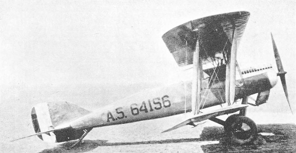
Dayton-Wright XB-1A with experimental installation of Curtiss D-12 engine.
Bristol F.2A and F.2B
<...>
The United States of America entered the war on April 6th, 1917, and set about the production of aircraft on a characteristically ambitious scale. The initial “Procurement Program” planned for the immediate acquisition of 7,375 aircraft, and the ultimate aim was the production of no fewer than 20,475 machines in twelve months. A substantial number of these aircraft were of British design. Towards the end of 1917 it was arranged that the Bristol Fighter would be produced by the Curtiss Aeroplane and Motor Corporation, and 2,000 were ordered. Two Bristol-built airframes were sent as samples to the Curtiss works.
The Curtiss-built machines were to have had the 300 h.p. Wright-built Hispano-Suiza engine, but political pressure was brought to bear in favour of the American Liberty 12, which was substituted for the Wright-Hispano. This was done in defiance of the strenuous opposition of the British & Colonial Aeroplane Co., for Captain Barnwell knew that the Liberty was too bulky and too heavy for the aeroplane.
Responsibility for the engineering behind the production of the Liberty-powered Bristol Fighter rested with the U.S. Government until the production programme was well advanced. Even when the Government relinquished that responsibility, the Curtiss company were not allowed to make changes of any magnitude. At an early stage, Curtiss engineers realised that Barnwell was correct in thinking that the installation of the Liberty engine in the Bristol Fighter would not be satisfactory; they therefore began to design a completely new aircraft (the Curtiss CB) to use the Liberty and to perform the same duties as the Bristol.
The installation of the Liberty engine in the Bristol Fighter was clumsy; the radiators were badly placed; and the aeroplane was nose-heavy and thoroughly unpleasant to fly. The first machine was completed in March, 1918, and was delivered to the U.S. Air Service during the following month. Twenty seven were built before production was halted and the remainder of the contract cancelled. Blind to their own blunder in fitting the Liberty to an aeroplane unsuited to the engine, the U.S. Army shifted the blame on to the innocent aircraft and condemned the Bristol Fighter as dangerous.
Another version of the design was, however, ordered in large quantities in America. The Engineering Division of the Bureau of Aircraft Production undertook the fairly extensive re-design of the Bristol Fighter and evolved two designs, both for aircraft which had completely re-designed structures: one version was powered by the 300 h.p. Hispano-Suiza, and was designated USB-1; the other was designed for the 290 h.p. Liberty 8, and was designated USB-2. An optimistic order for 2,000 machines of the USB type was placed.
These aircraft had veneer-covered fuselages of faired contours, and the area of their vertical tail assembly was increased. Many other detail modifications were made, and the equipment of the machines was different from that of the standard British-made Bristol F.2B.
Some standard Bristol Fighter airframes had been sent to America for experimental purposes. One was fitted with a 300 h.p. Hispano-Suiza, and had the McCook Field Project No. P.30; a second had one of the first eight-cylinder Liberty 8 engines of 290 h.p., and the Project No. P.37. The latter Bristol crashed before performance tests were carried out. These two Bristol Fighters have been referred to as the USB-1 and USB-2 respectively, but that is incorrect. In the summer of 1918, the construction of twelve Bristol Fighters was begun at McCook Field. The intention was to build eight machines to the basic Bristol design, four with Hispano-Suiza engines and four with the new and re-designed Liberty 8; and the remaining four were to be structurally similar but with veneer-covered fuselages, two having Hispano-Suizas and two Liberty 8s. Work lagged badly, however, and the construction of the first eight aircraft was finally stopped in September, 1918.
Work was still proceeding on the design of the USB-1 and USB-2, which were re-designated USXB-1 and USXB-2 at about this time. A number of fuselages of slightly different design were tested statically, and construction of two prototypes was begun.
The four Bristol F.2Bs with veneer-covered fuselages were still in hand, but in October, 1918, the construction programme was altered to consist of only two USXB-1s and two USXB-2s. This plan was retained until the Liberty 8 engine was abandoned in 1919, whereupon the USXB-2s were modified to take the 300 h.p. Hispano-Suiza, and all four machines emerged in July, 1919, under the designation Engineering Division XB-1A.
The order for 2,000 aircraft of USB type was cancelled at the time of the Armistice, but during 1920 and 1921 forty XB-1As were built by the Dayton-Wright concern. These production machines had the 330 h.p. Wright H engine, and their all-up weight was about 800 lb greater than that of the original XB-1A. In 1921, one of the production XB-1As was fitted with the 350 h.p. Packard 1A-1237 engine; and another (A.S.64156) was used as a test-bed for the Curtiss D-12.
<...>
<...>
The United States of America entered the war on April 6th, 1917, and set about the production of aircraft on a characteristically ambitious scale. The initial “Procurement Program” planned for the immediate acquisition of 7,375 aircraft, and the ultimate aim was the production of no fewer than 20,475 machines in twelve months. A substantial number of these aircraft were of British design. Towards the end of 1917 it was arranged that the Bristol Fighter would be produced by the Curtiss Aeroplane and Motor Corporation, and 2,000 were ordered. Two Bristol-built airframes were sent as samples to the Curtiss works.
The Curtiss-built machines were to have had the 300 h.p. Wright-built Hispano-Suiza engine, but political pressure was brought to bear in favour of the American Liberty 12, which was substituted for the Wright-Hispano. This was done in defiance of the strenuous opposition of the British & Colonial Aeroplane Co., for Captain Barnwell knew that the Liberty was too bulky and too heavy for the aeroplane.
Responsibility for the engineering behind the production of the Liberty-powered Bristol Fighter rested with the U.S. Government until the production programme was well advanced. Even when the Government relinquished that responsibility, the Curtiss company were not allowed to make changes of any magnitude. At an early stage, Curtiss engineers realised that Barnwell was correct in thinking that the installation of the Liberty engine in the Bristol Fighter would not be satisfactory; they therefore began to design a completely new aircraft (the Curtiss CB) to use the Liberty and to perform the same duties as the Bristol.
The installation of the Liberty engine in the Bristol Fighter was clumsy; the radiators were badly placed; and the aeroplane was nose-heavy and thoroughly unpleasant to fly. The first machine was completed in March, 1918, and was delivered to the U.S. Air Service during the following month. Twenty seven were built before production was halted and the remainder of the contract cancelled. Blind to their own blunder in fitting the Liberty to an aeroplane unsuited to the engine, the U.S. Army shifted the blame on to the innocent aircraft and condemned the Bristol Fighter as dangerous.
Another version of the design was, however, ordered in large quantities in America. The Engineering Division of the Bureau of Aircraft Production undertook the fairly extensive re-design of the Bristol Fighter and evolved two designs, both for aircraft which had completely re-designed structures: one version was powered by the 300 h.p. Hispano-Suiza, and was designated USB-1; the other was designed for the 290 h.p. Liberty 8, and was designated USB-2. An optimistic order for 2,000 machines of the USB type was placed.
These aircraft had veneer-covered fuselages of faired contours, and the area of their vertical tail assembly was increased. Many other detail modifications were made, and the equipment of the machines was different from that of the standard British-made Bristol F.2B.
Some standard Bristol Fighter airframes had been sent to America for experimental purposes. One was fitted with a 300 h.p. Hispano-Suiza, and had the McCook Field Project No. P.30; a second had one of the first eight-cylinder Liberty 8 engines of 290 h.p., and the Project No. P.37. The latter Bristol crashed before performance tests were carried out. These two Bristol Fighters have been referred to as the USB-1 and USB-2 respectively, but that is incorrect. In the summer of 1918, the construction of twelve Bristol Fighters was begun at McCook Field. The intention was to build eight machines to the basic Bristol design, four with Hispano-Suiza engines and four with the new and re-designed Liberty 8; and the remaining four were to be structurally similar but with veneer-covered fuselages, two having Hispano-Suizas and two Liberty 8s. Work lagged badly, however, and the construction of the first eight aircraft was finally stopped in September, 1918.
Work was still proceeding on the design of the USB-1 and USB-2, which were re-designated USXB-1 and USXB-2 at about this time. A number of fuselages of slightly different design were tested statically, and construction of two prototypes was begun.
The four Bristol F.2Bs with veneer-covered fuselages were still in hand, but in October, 1918, the construction programme was altered to consist of only two USXB-1s and two USXB-2s. This plan was retained until the Liberty 8 engine was abandoned in 1919, whereupon the USXB-2s were modified to take the 300 h.p. Hispano-Suiza, and all four machines emerged in July, 1919, under the designation Engineering Division XB-1A.
The order for 2,000 aircraft of USB type was cancelled at the time of the Armistice, but during 1920 and 1921 forty XB-1As were built by the Dayton-Wright concern. These production machines had the 330 h.p. Wright H engine, and their all-up weight was about 800 lb greater than that of the original XB-1A. In 1921, one of the production XB-1As was fitted with the 350 h.p. Packard 1A-1237 engine; and another (A.S.64156) was used as a test-bed for the Curtiss D-12.
<...>
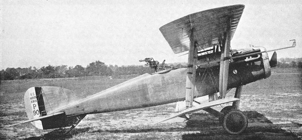
The Engineering Division XB-1A