P.Hare Royal Aircraft Factory (Putnam)
F.E.3 (A.E.1)
This quite remarkable two-seater, which included several novel and ingenious design features, was built in 1913 and was also known as the A.E.1, or Armed Experimental. It was conceived expressly to carry a Coventry Ordnance Works (COW) gun, which fired a one-pound shell, in an effort to provide the flying services with a weapon for which it was confidently expected there would be an eventual demand, although there was no immediate need. S J Waters appears to have had overall responsibility for the design, assisted by messrs Beadle, Folland, Reynolds and Swan.
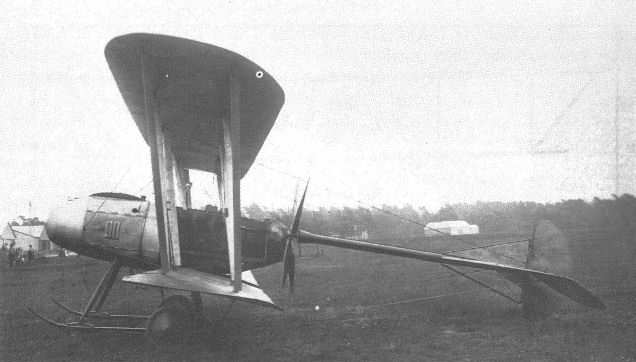
As was almost inevitable for a gun-carrier, the machine was a pusher, power being provided by a water-cooled, six-cylinder in-line Chenu engine of 100hp. This was mounted well forward in the nacelle so that, in the event of a crash, there was no risk of it breaking free and crushing the pilot, a common failing of most pushers. A shaft extended rearwards from the engine along the bottom of the nacelle, driving the propeller via a chain running in an oil-tight case behind the pilot's seat. In an attempt to eliminate the drag of the braced tailbooms normally associated with pusher designs, the tailplane was carried on the end of a single tailboom which was supported on bearings at the end of the propeller shaft and by bracing wires running to the upper wing and to the undercarriage.
Surviving drawings suggests that there was some indecision as to how the fully enclosed engine was to be cooled. At least one drawing shows extensive surface radiators along the top of the nacelle, following its contour from nose to cockpit rim. However, as finally built, the forward portion of the nacelle was clad in aluminium sheet, over a framework of steel tube, and the remainder was clad in plywood. The radiators were mounted inside the nacelle, cooling air being admitted through a circular hole in the nose. The wing and tail surfaces were of entirely conventional construction, being of fabric covered spruce, and their design clearly owed a great deal to the contemporary F.E.2, as did the undercarriage.
Test flying, undertaken by Geoffrey de Havilland, assisted by Ronald Kemp, revealed that the tail was not sufficiently rigid for satisfactory service, and the tests were discontinued without the gun being fired in flight. It was, however, tested with the machine suspended from the roof of one of the Farnborough airship sheds to establish that the gun's recoil would not pose a problem in flight.
The F.E.3's eventual fate is not recorded, but it is possible that rather more than the lessons learned from its trials was incorporated in its successor, the F.E.6.
Powerplant: 100hp eight-cylinder Chenu
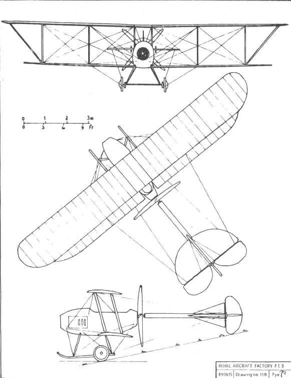
Dimensions:
span 40ft 0in;
chord 5ft 9in;
gap 6ft 4in;
wing area 436 1/2sqft;
incidence 3°
dihedral 1 1/2°;
length 29ft 3in;
height 11ft 3in.
Weights: 1,400lb (empty); 2,080lb (loaded).
Performance:
max speed 75mph at sea level;
ceiling 5,000ft;
climb 350ft/min to 1,000ft.
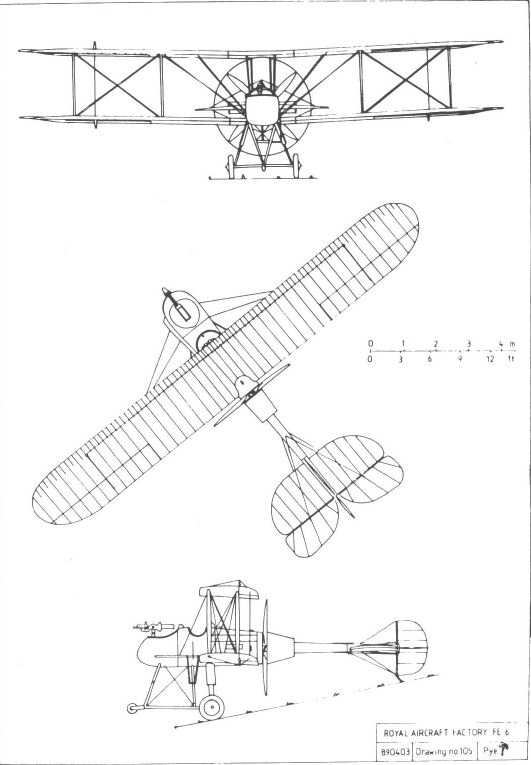
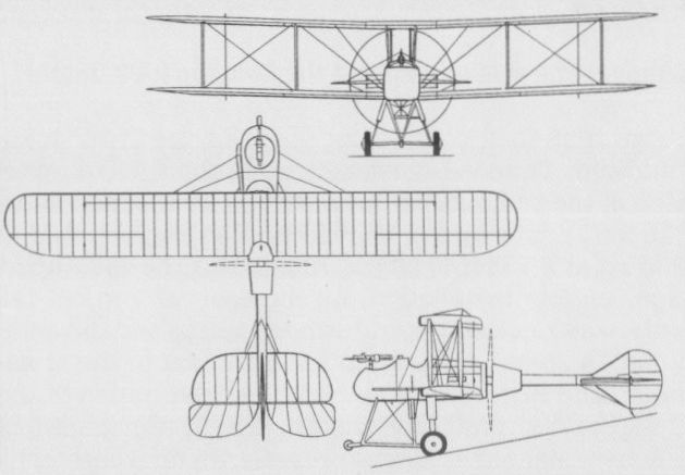
F.E.6
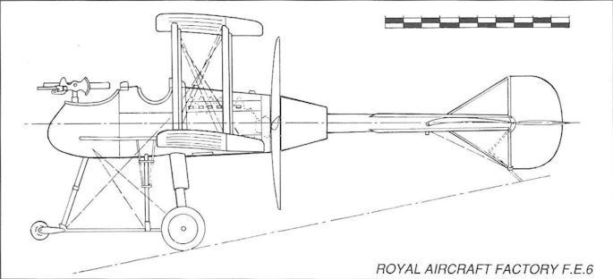
Designed early in 1914, the F.E.6 continued to explore the ideas previously incorporated in the F.E.3 and, like its predecessor, carried a one-pounder quick-firing Coventry Ordnance Works gun. It closely followed the layout of the earlier machine and was again a pusher, but, being a slightly heavier design, it was powered by the more powerful 120hp six-cylinder Austro-Daimler. The wings were standard R.E.5 components, and the tall oleo undercarriage incorporated a small nose wheel, making it very similar in appearance to that of the F.E.2b. The tail surfaces, like those of the F.E.3, were carried at the end of a single tubular tailboom attached to a bearing on the end of the propeller shaft. Unlike the boom of the earlier machine, this one was a cantilever structure, with no bracing wires to support it. The control wires operating the rudder and elevators were run inside the tailboom tube, thus eliminating another potential source of drag.
The F.E.6's fin and rudder, in common with those of many of its contemporaries, appear to have been of insufficient area to balance the keel area forward of the centre of gravity. This may have been one of the reasons why its flying career, at the hands of Frank Goodden, was very brief. Following a test flight on 14 November 1914, a heavy landing resulted in some damage to the undercarriage, but the aircraft was not repaired. Instead the machine was broken up, the wings being returned to store as R.E.5 spares. As with the F.E.3, it is extremely doubtful if the gun was ever fired, at least not while the machine was in flight.
Powerplant: 120hp eight-cylinder Austro-Daimler
Dimensions:
span 49ft 4in;
chord 6ft 0in;
wing area 542 sq ft;
length 29ft 6in;
height 15ft 0in.
Weights:
2,000lb (empty);
2,630lb (loaded).
Показать полностью
M.Goodall, A.Tagg British Aircraft before the Great War (Schiffer)
Deleted by request of (c)Schiffer Publishing
FE.3 biplane (AE.l Armed Experimental)
This machine was a two-seater pusher designed, under the leadership of S.J. Waters, to carry a one-pounder COW gun. The testing, by de Havilland and Kemp, revealed the inadequate rigidity of the tail and flying was abandoned. The effect of the recoil of the gun was assessed with the machine suspended from a hangar roof.
The water-cooled engine was mounted at the front of the nacelle and drove a four-bladed propeller through a shaft and enclosed chain. A circular air intake in the nose provided air to a radiator in front of the crew, the air escaping through louvered panels in the sides.
The tail unit was mounted on a single tubular boom, with a support for the extension shaft behind the propeller, the tail itself being braced by wires to the wings and undercarriage. Triangular fins, above and below the boom, formed a post for the tall rudder; a large semicircular tailplane and divided elevators completed the tail unit.
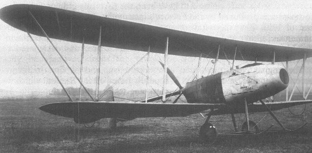
The wings were of unequal span, with the top overhang braced by struts. Lateral control was by warping. Tests of the machine, which was built in 1913, were not continued, but a successor of the same general configuration followed in 1914.
Power: 100hp Chenu six-cylinder inline water-cooled.
Data
Span 40ft
Chord 5ft 9in
Gap 6ft 4in
Area 436 1/2 sq. ft
Length 29ft 3 In
Height 11ft 3in
Weight 1,400lb.
Weight allup 2,080lb.
Speed 75mph
Rate of climb 350ft per min to 1,000ft
Ceiling 5,000ft
FE.6 biplane
The FE.6 was designed and built in 1914 as a successor to the FE.3, to carry on the work of investigating the requirements for the carnage of the one pounder COW gun. Frank Goodden flew the aircraft on 14 November 1914 for the first time, but the flight resulted in damage which, although not severe, was not repaired, indicating problems of a more fundamental nature.
The aircraft was a heavier and larger version of the FE.3 and was of the same basic layout. The tail boom was more substantial and was not braced externally, and had space to run the tail surface controls internally. The boom would, of necessity, have been firmly anchored back to the structure of the aircraft. The gun was mounted above the lip of the front cockpit to fire forward, but was probably never actually fired.
Power: 120hp Austro-Daimler six-cylinder inline watercooled
Data
Span 49ft 4in
Chord 6ft
Area 542 sq. ft
Length 29ft 6in
Height 15ft
Weight 2,000 lb.
Weight allup 2,630lb.
Показать полностью
P.Lewis The British Fighter since 1912 (Putnam)
Although, in the straightforward two-bay pusher biplane layout of the F.E.2, the Factory’s designers had played safe by following a formula which was by then well proven, tne next machine to be built within the Fighting Experimental category, the F.E.3, displayed an innovation which was a startling departure from the conventional. Designed primarily as a gun-carrier with a crew of two, it appeared at Farnborough in 1913. With a span of 48 ft. and a loaded weight of 2,100 lb., the machine was larger and heavier than its predecessor, the F.E.2. Stagger had been introduced in the wing cellules and the nacelle enclosed the 80 h.p. Chenu engine which received its supply of cooling air by way of the circular nose orifice. The four-blade propeller was mounted at the rear end of the nacelle and was remarkable in that it revolved around the single metal tubular boom which carried the tail surfaces and which replaced the structure of a quartette of braced wooden booms normally utilized for the purpose. The wheel and skid undercarriage was quite conventional. The F.E.3’s alternative designation was A.E.1, a title which is likely to have indicated Armed Experimental in view of the aircraft’s intended purpose. The Coventry Ordnance Works 1-5-pounder quick-firing gun was mounted inside the nacelle to fire its shells through the nose opening, trials of the installation being carried out during the Summer of 1913 in the single example built of the F.E.3.
<...>
While the opening scenes of the conflict were being enacted on the Continent, at Farnborough the Royal Aircraft Factory’s designers were deeply involved in new projects in the midst of the greatly accelerated programme thrust on their resources in the strident urgency of war. Several Fighting Experimentals were numbered among their proposals and incorporated some widely diverse ideas in layout.
The two-seat F.E.6, built in 1914, carried on the unusual theme demonstrated in the F.E.3 of the tail unit being borne on a single metal tubular boom which passed through the pusher propeller’s boss. The F.E.6 had the more powerful 120 h.p. Austro-Daimler for power and the layout again provided the gun with uninterrupted forward fire. As was the case with the majority of what might be classed as freak designs in search of the ideal, the F.E.6 was too radical to be successful as an operational machine and failed to be ordered for production.
Показать полностью
F.Mason The British Fighter since 1912 (Putnam)
Royal Aircraft Factory F.E.3/A.E.1
Built at the Royal Aircraft Factory early in 1913, the F.E.3 (Fighting Experimental) was an interesting two-bay two-seat pusher biplane designed as a gun-carrier. The principal feature of note was the absence of the customary pairs of tail booms to support the empennage, their place being taken by a single tubular boom around which the hollow propeller shaft rotated. Torsional rigidity of the tail unit was achieved by plentiful bracing wires, tensioned between the wings and sternpost, and between the landing skids and tailplane.
Power was provided by a French 80hp Chenu engine (of somewhat unreliable reputation that had recently powered Coventry Ordnance and Martin Handasyde sporting aircraft) which drove the pusher propeller by means of a shaft under the nacelle to a chain drive at the rear.
After brief flying trials in the hands of de Havilland and other Farnborough pilots the aircraft was fitted with a single 1 1/2-pdr Coventry Ordnance quick-firing gun which fired through the engine cooling intake, but only ground firing tests were performed during the summer of 1913.
The aircraft was also referred to as the A.E.1 (Armoured Experimental), but was not proceeded with, and saw no service.
Type: Single pusher engine, two-seat, two-bay biplane.
Manufacturer: Royal Aircraft Factory, Farnborough, Hants.
Powerplant: One 80hp Chenu engine with shaft and chain drive to four-blade pusher propeller mounted on hollow shaft through which passed the single tail support boom.
Structure: Mixed wood and metal nacelle structure with metal and fabric covering; twin-spar wooden three-bay wing structure with moderate stagger and fabric covering. Single tubular tail support boom.
Dimensions: Span, 48ft; length, 33ft; wing area, 480 sq ft.
Weight Loaded: 2,100lb.
Performance: Max speed, 75 mph at sea level; initial climb, 350 ft/min; ceiling, 5,000ft.
Armament: Ground trials with 37mm 1 1/2-pdr COW gun in nose of nacelle.
Prototype: One. No production.
RAF F.E.6
Relatively little is known of the F.E.6, other than it was a two-bay, single-engine pusher biplane which was built in the second half of 1914 by the Royal Aircraft Factory, and was powered by a 120hp Austro-Daimler driving a four-blade propeller. It followed the unusual configuration of the F.E.3 in that the tail unit was carried on a single steel boom which extended aft through the propeller shaft.
From the accompanying sketch, taken from a Factory drawing, the F.E.6 can be seen to possess no wing stagger and that ailerons were fitted to the upper and lower wings. The mainwheels of the undercarriage appear to have been carried on oleo struts and there was a small auxiliary nosewheel. The gun armament may have been a 6-pounder Davis recoilless weapon. Whether the aircraft was built and flown exactly to this design is not known.
Показать полностью
W.Green, G.Swanborough The Complete Book of Fighters
ROYAL AIRCRAFT FACTORY F.E.3 UK
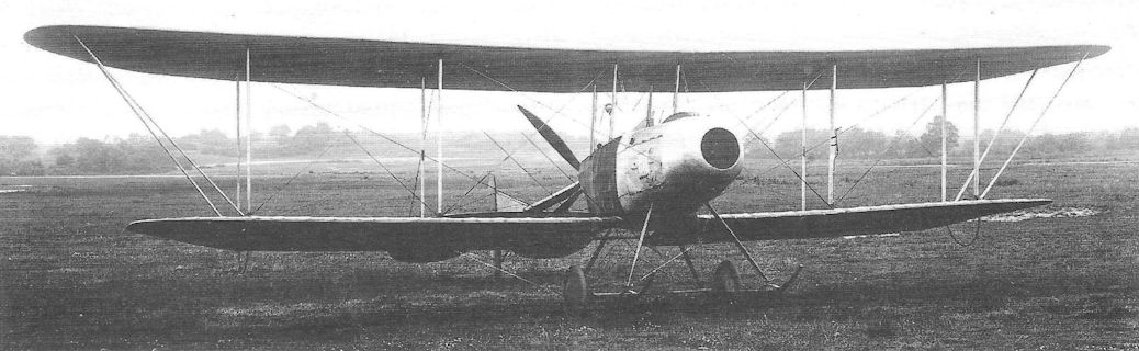
Located at Farnborough and engaged primarily in aeronautical research, the Royal Aircraft Factory (so named in April 1912) was responsible for the design and development of a number of warplanes during World War I. In accordance with the factory’s purpose they received designations combining a prefix letter (at first indicating the general configuration, but later the role) with E for experimental (although several, such as the B.E.2, F.E.2, R.E.8 and S.E.5, were to be built in large numbers). Built in 1913, the F.E.3 was thus the third design in the “Farman Experimental” series of pusher biplanes, and was designed to carry a COW one-pounder quick-firing gun. Alternatively known as the A.E.I (“Armoured Experimental”), the two-seat F.E.3 was a two-bay biplane with overhanging upper wing, and a four-bladed pusher propeller driven by a shaft and chain from the 100 hp Chenu eight-cylinder water-cooled inline engine mounted in the front of the fuselage. The large cruciform tail unit was carried on a single central boom secured through the hollow propeller shaft and braced by wires to the upper wing and the undercarriage. Flight tests showed that the tail attachment was not sufficiently rigid and the gun, fitted in front of the fuselage, was fired only in static tests at Farnborough after flight testing was abandoned. The F.E.3 used fabric-covered wooden construction for the wings and tail unit, but the fuselage nacelle was of steel tube construction with aluminium and plywood skinning. A large central orifice in the nose took in air for the engine radiators, which were inside the nacelle.
Max speed, 75 mph (121 km/h) at sea level.
Initial climb, 350 ft/min (1,78 m/sec).
Service ceiling, 5,000 ft (1525 m).
Empty weight, 1,400 lb (635 kg).
Loaded weight, 2,080 lb (943 kg).
Span, 40 ft 0 in (12,19m).
Length, 29 ft 3 in (8,91m).
Height, 11 ft 3 in (3,43 m).
Wing area, 436.5 sq ft (40,55 m2).
ROYAL AIRCRAFT FACTORY F.E.6 UK
Of similar construction to the F.E.3, the F.E.6 was built in 1914 and was powered by a 120 hp Austro-Daimler six-cylinder water-cooled engine. Standard R.E.5 components were used for the wings, which were of equi-span, and the tail unit was carried on a cantilever boom, without bracing wires. The F.E.6 was flown at Farnborough on 14 November 1914 but this may have been its only flight, and, if fitted, the COW gun that it was designed to carry was not fired.
Empty weight, 2,000 lb (907 kg).
Loaded weight, 2,630 lb (1193 kg).
Span, 49 ft 4 in (15,03 m).
Length, 29 ft 6 in (8,99 m).
Height, 15 ft 0 in (4,57 m).
Wing area, 542 sq ft (50,35 m2).
Показать полностью
P.Lewis British Aircraft 1809-1914 (Putnam)
F.E.3/A.E.1
The F.E.3, known also as the A.E.1, was an experimental two-seat pusher gun-carrier built by the Royal Aircraft Factory in 1913. The propeller revolved around the single metal tubular boom which was intended later to be the sole support for the tail unit. The 80 h.p. Chenu engine was cooled through the circular opening in the nose of the nacelle. The F.E.3 was used for armament trials during the summer of 1913, equipped with the 1 1/2- pounder C.O.W. gun which fired through the nose opening. Span, 48 ft. Length, 33 ft. Wing area. 480 sq. ft. Weight loaded. 2,100 lb. Maximum speed, 75 m.p.h. Climb, 350 ft./min. Ceiling, 5,000 ft.
Показать полностью
J.Bruce British Aeroplanes 1914-1918 (Putnam)
THE F.E.3 was a remarkable single-engined pusher biplane which was built in 1913. It had only a single tail-boom which passed through the hollow airscrew shaft, and was powered by the 100 h.p. Chenu engine. The type did not go into production, and saw no war service. In the summer of 1913 it was used as a static test-bed for experiments in the firing of a one-pounder gun made by the Coventry Ordnance Works. These significant tests showed that the firing of a gun from an aeroplane would be unlikely to have any detrimental effect upon the aircraft’s stability in flight.
The F.E.6 was built in 1914; it was a two-seat pusher built on similar lines to the F.E.3 with a single tail-boom through the hollow airscrew shaft, and its engine was a 120 h.p. Austro-Daimler.
Показать полностью
H.King Armament of British Aircraft (Putnam)
F.E.3. The F.E.3 was a remarkable aeroplane, especially so as it was built as early as 1913. The tail was carried on a single boom, which passed through the hollow airscrew shaft, and the armament was a 1-pounder Coventry Ordnance Works gun. This gun was apparently never fired from the aircraft in flight but was tested in the summer of 1913 with the F.E.3 suspended by ropes from a gantry. It was established that flight stability would not be unduly affected.
F.E.6. This two-seat pusher fighter was built in 1914 as a development of the F.E.3 theme and was similarly armed with a Coventry Ordnance Works 1-pounder gun. This was (or was to be) installed on a pillar mounting in the nose.
Показать полностью